134 SEALS HANDBOOK EXPANSION JOINTS – RUBBER 137 Specma-Elaflex variants Yellow ring For mineral...
24
134 EXPANSION JOINTS – RUBBER – FABRIC – STEEL
Transcript of 134 SEALS HANDBOOK EXPANSION JOINTS – RUBBER 137 Specma-Elaflex variants Yellow ring For mineral...

134 E X P A N S I O N J O I N T S– R U B B E R – F A B R I C – S T E E L

To consider when selecting expansion joints:Expansion joints have varying designs and are manufactured from various materials to suit different applications. The principal basic features can be summarised as follows:
Materials:The selection of material is dependent on the media that is to be sealed, and its pressure and temperature.
The most common expansion joints are divided into the following groups:Rubber expansion joints:normally used in pipelines containing liquids at temperatures up to max. +130°C.
Fabric expansion joints:used for hot media, e.g. flue gases up to max. +1000°C.
Steel expansion joints:suitable for hot liquids and gases, e.g. hot water and exhaust gases up to max. +1300°C.

Specma-Elaflex expansion joints
The stated limit values apply under favourable conditions. Do not utilise more than one maximum value at a time. If in doubt please contact us, we will be happy to offer advice.
S P E C M A S E A L S H A N D B O O K
E X P A N S I O N J O I N T S – R U B B E R
136
Material description:Specma-Elaflex rubber expansion joints are used to absorb movement and vibration in pipelines. This prevents the dissemination of noise and vibration, reducing the risk of pipe breaks and stress. Assembly is easy as Specma-Elaflex expansion joints have rotating flanges, reducing the need for exact alignment.
Design:The rubber bellows are reinforced with strong nylon or polymer cord (Rotex), which is anchored in reinforcement rings of steel wire in the end flanges of the bellows. A special version is also available with a lining and internal PTFE support ring.
Flanges:Rotatable zinc-plated steel flanges as per EN standard PN 10, therefore suitable also for PN 16 up to DN 150. Flanges of other materials and as per other standards can be supplied to order, e.g. hot-dip galvanised or stainless flanges, aluminium flanges, ASME flanges, SAE flanges, mini flanges etc.
Allowable range of movement:
Compression: 30 mm.
Elongation: 30 mm.
Angular 5°-35°, greatest for smallest deflection: dimension.
Lateral displacement: ±30 mm.
Not all maximum values can be utilised at the same time – see Table 1.
For Rotex – see Table 4.
Pressure:
Operating pressure, nylon cord-reinforced16 bar at +50°C 12 bar at +70°C 10 bar at +90°C
Operating pressure, Rotex16 bar at +70°C 10 bar at +100°C 6 bar at +110°C
Test pressure, cold water25 bar
Burst pressure, depending on quality and dimension 60-100 bar
Vacuum:
At a normal installation length of 130 mm:0-8 mWG
With an internal support ring:6-10 mWG - depending on size.
See Tables 1 and 3. (not applicable to expansion joints with PTFE lining).
Installation:Specma-Elaflex expansion joints are intended for assembly onto welding neck flanges. If flat slip-on welding flanges are used, check that the internal diameter of the flange contact surface with the rubber edge of the bellows is not too large. See installation guidance on page 142.
Tightening torque:
Up to DN 80 60 Nm
DN 100-600 80-100 Nm
The pipework must be well aligned and anchored. Detailed installation instructions are provided on subsequent pages.
Approvals:Specma-ElaflexisapprovedbyLloyd'sRegisterof Shipping for use in cooling water, freshwater andballastlines.AlsoapprovedbyDetNorskeVeritas for cooling water lines, as well as for hydraulicandlubricatingoilafterspecialtesting.
ApprovalsarealsoprovidedbyFreieundHansestadt Hamburg, TÜV-Technischer Überwachungsverein,Hannover,GermanischerLloyd,BureauVeritas,USSRRegisterofShipping, Wehrwissenschaftliches Institut für Materialuntersuchungen,BWBFederalOfficeofDefenceTechnologyandProcurement.
Selection of rubber quality:See the Resistance table. Contact Specma Seals if you are in any doubt.
Guarantee:We provide a guarantee for the rubber bellow of two years from the delivery date. If the bellow fails during that period we will supply a new bellow as a replacement.
This guarantee applies on condition that the expansion joint has been assembled and used according to our written instructions. The guarantee does not cover damage arising from external influences or any consequential damage.

S P E C M A S E A L S H A N D B O O K
E X P A N S I O N J O I N T S – R U B B E R
137
Specma-Elaflex variants
Yellow ring
For mineral oil products, petrol etc. Also suitable for cooling water emulsions containing corrosion protection oils up to +90°C. Electrical conductivity: R 103-106 ohm.
Inner rubber: Nitrile
Reinforcement:Nyloncord
Outer rubber: Chloroprene
Flanges: Zinc-plated carbon steel
Yellow ring is recommended for all petroleum based products with less than 50% aromatics. Also suitable for emulsions of hot water/oil.For further details see the Resistance Table.
Green ring
For acids, alkalis, chemicals etc. up to +80°C.
Innerrubber: Hypalon(CSM)
Reinforcement:Nyloncord
Outerrubber: Hypalon(CSM)
Flanges: Zinc-plated carbon steel
Green ring is particularly suitable for strongly oxidising acids such as nitric acid, acetic acid, sulphuric acid etc. The temperature must be reduced for very aggressive acids. Green ring is also suitable for compressed air containing oil vapour up to +90°C.For further details see the Resistance Table.
Red ring
For cold and hot water up to +90°C. Ideal for industrial water, drinking water and seawater. Approved for drinking water. Also suitable for many industrial chemicals such as acids, alkalis, alcohols, esters, ketones etc. Note: Not oil resistant.
Innerrubber: EPDM/Butyl
Reinforcement:Nyloncord
Outer rubber: EPDM
Flanges: Zinc-plated carbon steel
Ideal for cooling water lines in vessels, where non-petroleum based corrosion inhibitors are used. Note: High operating temperatures cause continuous ageing of the nylon cord. Thus the burst pressure decreases over time. RSK nos. 5070920 to 5070933 (Swedish Pipe Wholesalers Organisation – HVAC).For further details see the Resistance Table.
Rotex
With a double red marking for hot water. Approved for 10 bar +100°C, 6 bar +110°C (intermittent up to +130°C). Designed for hot water, steam, superheated air, industrial chemicals such as acids, alkalis, alcohols, esters, ketones, etc. Note: Not oil resistant, not approved for drinking water.
Inner rubber: EPDM
Reinforcement:Polymercord
Outer rubber: EPDM
Flanges: Zinc-plated carbon steel
Rotex is specially designed for safe long-term use at high operating temperatures in hot water systems such as district heating plants etc. Approved by TÜV in Germany for 10 years of use at +110°C. Rotex has special installation data and allowable range of movement compared with the standard qualities, see table 4. For further information, see
the Resistance table.CR
For cold and hot water up to +70°C. Suitable for cooling water and drainage systems with water containing oil or weakly alkaline water. Not suitable for drinking water, acids or industrial chemicals.
Innerrubber: Chloroprene,black
Reinforcement:Nyloncord
Outerrubber: Chloroprene,black
Flanges: Zinc-plated carbon steel
Available from DN 32 to DN 300. CR has slightly limited allowable range of movement compared with the standard qualities. RSK nos. 5070901 to 5070912 (Swedish Pipe Wholesalers Organisation – HVAC).For further details see the Resistance Table.
Further variants of Specma-Elaflex:White ring:
Inner rubber of white nitrile for foods, drinking water etc.
Orange ring:
For LPG, mineral oil products. Operating pressure max. 20 bar.
ERP:
For sanitary applications
Other information:Red ring, Yellow ring and Rotex: Also available in longer installation lengths.
Yellow ring Green ring Red ring Rotex CR

The stated limit values apply under favourable conditions. Do not utilise more than one maximum value at a time. If in doubt please contact us, we will be happy to offer advice.
Table 1:Dimension table for Specma-Elaflex with For Yellow ring, Green ring, Red ring and CR**) standard flanges as per EN Note: Not for Rotex. See separate table Flange dimensions Operating Test- Max. vacuum Allowable range of movement Installation pressure pressurised at length (cold L = normal water)
Connec- without with Lateral Angle of tion Pressure support support L L L displac- deflec-
DN class D k g I1) b W ring ring normal mini max ment tion Weight min. max.
mm in PN mm mm mm mm Ø mm mm bar bar mWG mWG mm mm mm ±mm ± kg mm mm
25***) 1” 10-16 115 85 66 4x14 18 81 16 25 8 - 130 100 160 30 35° 2.3 120 135
32 1” 10-16 140 100 66 4x18 18 81 16 25 8 - 130 100 160 30 35° 2.7 120 135
40 1.1/2” 10-16 150 110 70 4x18 19 86 16 25 8 - 130 100 160 30 35° 4.0 120 135
50 2” 10-16 165 125 90 4x18 19 96 16 25 4 10 130 100 160 30 35° 4.5 120 135
65 2.1/2” 10-16 185 145 105 4x18 19 111 16 25 4 10 130 100 160 30 30° 5.0 120 135
80 3” 10-16 200 160 116 8x18 21 122 16 25 4 10 130 100 160 30 30° 6.5 120 135
100 4” 10-16 220 180 138 8x18 21 142 16 25 3 10 130 100 160 30 25° 8.0 120 135
125 5” 10-16 250 210 165 8x18 21 168 16 25 - 10 130 100 160 30 25° 9.5 120 135
150 6” 10-16 285 240 190 8x23 21 192 16 25 - 7 130 100 160 30 20° 13.2 120 135
200 8” 10 340 295 250 8x23 26 252 16*) 25*) - 7 130 100 160 30 15° 17.6 120 135
250 10” 10 395 350 300 12x23 26 302 16*) 25*) - 6 130 100 160 30 10° 22.5 120 135
300 12” 10 445 400 350 12x23 26 354 16*) 25*) - 10 130 100 160 30 10° 26.0 120 135
350 14” 10 505 460 410 16x23 26 430 10 16 - 10 200 150 230 30 8° 32.0 180 210
400 16” 10 565 515 455 16x26 26 480 10 16 - 10 200 150 230 30 8° 37.5 180 210
500 20” 10 670 620 555 20x26 28 580 10 16 - 10 200 150 230 30 6° 47.0 180 210
600 24” 10 780 725 670 20x30 28 680 10 16 - 10 200 150 230 30 6° 76.0 180 210
*) Operating pressure 16 bar, permitted only if the flanges are also designed for PN 16 (available to order). With PN 10 flanges, the permitted operating pressure is 10 bar and test pressure is 16 bar.
**) The limits specified in this table are applicable only with use of flanges with support rims.
***) DN 25 consists of a rubber bellow DN 32, with flanges DN 25 PN 10/16.1) Number of holes x hole diameter.
Note: DN 40 and DN 80 PN 10 also fit PN 6 (oval bolt holes).
S P E C M A S E A L S H A N D B O O K
E X P A N S I O N J O I N T S – R U B B E R
Technical data for Specma Elaflex expansion joints:
138
Support rim
InstallationdimensionsandallowablerangeofmovementforRotexexpansionjoints:The table shows installation dimensions and range of motion at +70°C. At +90°C the range of motion is 75%, and at +110°C 50% of the values below.
Connection DN Max. operating Allowable range of movement Installation pressure *) length
Lateral Angle of L L L displace- ang- standard min max ment tion Weight min max
mm mm ±mm
mm in. 70°C 100°C 110°C mm 70°C 70°C 70°C ±< kg mm mm
25**) 1” 16 10 6 130 100 160 20 30° 2.3 120 135 32 1” 16 10 6 130 100 160 20 30° 2.7 120 135 40 1.1/2” 16 10 6 130 100 160 20 30° 4.0 120 135
50 2” 16 10 6 130 100 160 20 30° 4.5 120 135 65 2.1/2” 16 10 6 130 100 160 20 30° 5.0 120 135 80 3” 16 10 6 130 100 160 20 30° 6.5 120 135
100 4” 16 10 6 130 100 160 20 20° 8.0 120 135 125 5” 16 10 6 130 100 160 20 20° 9.5 120 135 150 6” 16 10 6 130 100 160 20 20° 13.2 120 135
200 8” 16 10 6 130 100 160 20 12° 17.6 120 135 250 10” 16 10 6 130 100 160 20 12° 22.5 120 135 300 12” 16 10 6 130 100 160 20 12° 26.0 120 135
350 14” 10 10 6 200 150 230 20 8° 32.0 180 210 400 16” 10 10 6 200 150 230 20 8° 37.5 180 210 500 20” 10 10 6 200 150 230 20 8° 47.0 180 210 600 24” 10 10 6 200 150 230 20 8° 76.0 180 210
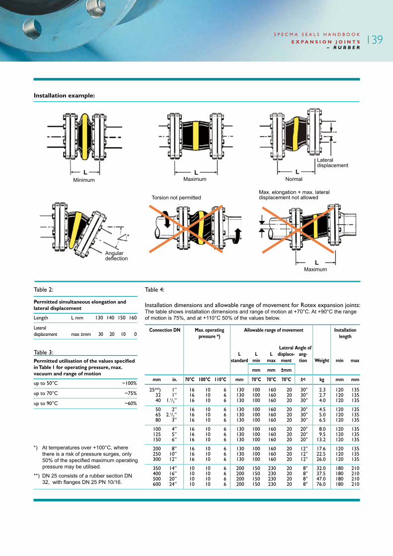
Installation example:
S P E C M A S E A L S H A N D B O O K
E X P A N S I O N J O I N T S – R U B B E R
Table 2:
Permitted simultaneous elongation and lateral displacement
Length Lmm 130 140 150 160
Lateral displacement max ±mm 30 20 10 0
Table 3:Permitted utilisation of the values specified in Table 1 for operating pressure, max. vacuum and range of motion
up to 50°C ~100%
up to 70°C ~75%
up to 90°C ~60%
*) At temperatures over +100°C, where there is a risk of pressure surges, only 50% of the specified maximum operating pressure may be utilised.
**) DN 25 consists of a rubber section DN 32, with flanges DN 25 PN 10/16.
Table4:
139
Minimum Maximum Normal
Angular deflection
Torsion not permitted
Maximum
Lateral displacement
Max. elongation + max. lateral displacement not allowed
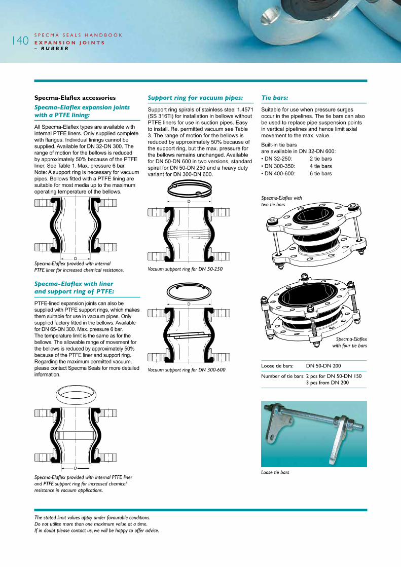
Specma-Elaflex accessoriesSpecma-Elaflex expansion joints with a PTFE lining:
All Specma-Elaflex types are available with internal PTFE liners. Only supplied complete with flanges. Individual linings cannot be supplied. Available for DN 32-DN 300. The range of motion for the bellows is reduced by approximately 50% because of the PTFE liner. See Table 1. Max. pressure 6 bar. Note: A support ring is necessary for vacuum pipes. Bellows fitted with a PTFE lining are suitable for most media up to the maximum operating temperature of the bellows.
Specma-Elaflex provided with internal PTFE liner for increased chemical resistance.
Specma-Elaflex with liner and support ring of PTFE:
PTFE-lined expansion joints can also be supplied with PTFE support rings, which makes them suitable for use in vacuum pipes. Only supplied factory fitted in the bellows. Available for DN 65-DN 300. Max. pressure 6 bar. The temperature limit is the same as for the bellows. The allowable range of movement for the bellows is reduced by approximately 50% because of the PTFE liner and support ring. Regarding the maximum permitted vacuum, please contact Specma Seals for more detailed information.
Specma-Elaflex provided with internal PTFE liner and PTFE support ring for increased chemical resistance in vacuum applications.
The stated limit values apply under favourable conditions. Do not utilise more than one maximum value at a time. If in doubt please contact us, we will be happy to offer advice.
Support ring for vacuum pipes:
Support ring spirals of stainless steel 1.4571 (SS 316Ti) for installation in bellows without PTFE liners for use in suction pipes. Easy to install. Re. permitted vacuum see Table 3. The range of motion for the bellows is reduced by approximately 50% because of the support ring, but the max. pressure for the bellows remains unchanged. Available for DN 50-DN 600 in two versions, standard spiral for DN 50-DN 250 and a heavy duty variant for DN 300-DN 600.
Specma-Elaflex with four tie bars
Specma-Elaflex with two tie bars
Tie bars:
Suitable for use when pressure surges occur in the pipelines. The tie bars can also be used to replace pipe suspension points in vertical pipelines and hence limit axial movement to the max. value.
Built-in tie bars are available in DN 32-DN 600:• DN 32-250: 2 tie bars• DN 300-350: 4 tie bars• DN 400-600: 6 tie bars
Vacuum support ring for DN 50-250
Vacuum support ring for DN 300-600
S P E C M A S E A L S H A N D B O O K
E X P A N S I O N J O I N T S – R U B B E R
Loose tie bars: DN 50-DN 200
Number of tie bars: 2 pcs for DN 50-DN 150 3 pcs from DN 200
Loose tie bars
140

Flame protection covers:
Covers made from impregnated glass fibre fabric, provided on the surface with a silver coloured, high temperature-resistant synthetic rubber layer. The flame resistant cover protects the Specma-Elaflex bellow from radiant heat and direct flames up to +800°C for approximately 30 min. Because of its split design, the cover can easily be installed over existing bellows and removed again for inspection. The counter flanges are covered by the flame resistant cover. The cover will not affect the allowable range of movement of the bellow. Specma-Elaflex expansion joints are approved by Germanischer Lloyd for use in pipelines containing fuel oil and lubricating oil, on condition that this flame protection cover is fitted.
Dimensions:
DN PN Yellow ring Green ring Red ring Rotex CR Vacuum support ring
25 10-16 x x 381102 x x -
32 10-16 381003 x 381103 x x -
40 10-16 381004 x x x x -
50 10-16 381005 x 381105 381305 x 383050
65 10-16 381006 x 381106 381306 x 383065
80 10-16 381008 x 381108 381308 x 383080
100 10-16 381010 x 381110 381310 x 383100
125 10-16 381012 x 381112 x x 383125
150 10-16 381015 x 381115 381315 x 383150
200 10 381020 x 381120 381320 x 383200
250 10 381025 x 381125 x x 383250
300 10 381030 x 381130 x x 383300
350 10 x x x x x x
400 10 x x x x x x
500 10 x x x x x x
600 10 x x x x x x
700 10 x - x x x -
800 10 x - x x x -
900 10 x - x x x -
1000 10 x - x x x -
Sizes marked with a part number are normally kept in stock while those marked with a cross are special order items.
Specma-Elaflex expansion joints with other pressure classes, installation lengths and flange standards are supplied on request.
Flame resistant cover for protection of expansion joint and counter flanges available for DN 25-500.
Protection sleeves for abrasive media:
If abrasive particles are present, it is recommended that the Specma-Elaflex bellows should be provided with an inner protection sleeve, which is fitted in the direction of flow. The protection sleeve has a flange which is clamped between the counter flange and the rubber flange of the bellow. Position a soft gasket
suitable for the purpose between the protection sleeve flange and the counter flange in the pipe system. The allowable range of movement of the bellows is restricted just to movement in the axial direction.
The inner protection sleeve is installed in the direction of flow of the medium. Complete with a soft gasket between the flange of the protection sleeve and the counter flange.
S P E C M A S E A L S H A N D B O O K
E X P A N S I O N J O I N T S – R U B B E R
141

Installation guidanceSpecma-Elaflex expansion joints are supplied ready for installation. The standard flanges rotate in all positions and have a support rim that facilitates assembly. The bolts can be installed from both directions (provided that the bolt has the correct length). The support rim means that the end of the bolt is kept at a safe distance from the rubber bellows in all positions within the permitted range of movement for the expansion joint.
Counterflanges:Soft gaskets are not necessary if the sealing surfaces on the counter flanges are the “correct” options according to the figures below. Otherwise a soft gasket must be fitted – as shown in Figure 5 – to prevent sharp edges cutting into the rubber flange and damaging it.
Pressure:The permitted operating and test pressures are dependent not only on the burst pressure of the rubber bellows, but also on the operating temperature and pressure class of the flanges. Detailed information can be found in Tables 1 and 3.
The burst pressure for cold water is between 60 and 100 bar depending on installation length, connection (DN) and tie bars.
The stated limit values apply under favourable conditions. Do not utilise more than one maximum value at a time. If in doubt please contact us, we will be happy to offer advice.
Vacuum:The maximum permitted vacuum depends on the connection, operating temperature, installation length and whether or not a vacuum support ring has been fitted. See Table 1. Even if a support ring is not installed the maximum permitted vacuum can be increased slightly, on condition that the installation length is reduced. If, on the other hand, a greater installation length is used, and a support ring has not been installed, the maximum permitted vacuum must be reduced correspondingly.
Weatherproof and heat resistance:The outer rubber is weatherproof, protecting the cord and inner rubber against ageing, mechanical wear and corrosion. The nylon cord is resistant to rot. Extra external protection is not normally necessary. A flame resistant cover must be fitted if there is a risk of fire. See previous page. Rubber bellows are flexible down to -30°C. The maximum temperature for each rubber grade is specified on the previous page. At higher operating temperatures account must be taken of the reduction in service life. The external rubber on yellow, green and red ring grades is not flameproof. When installing expansion joints in engine rooms on-board vessels, where the pipelines contain flammable media, a flame protection cover must be fitted.
Pressure loss:The flow-promoting design of the rubber bulb prevents turbulence. In consequence pressure loss is hardly measurable, even at large flow rates, and can therefore be disregarded.
Noise damping:Due to their unique design, Specma-Elaflex expansion joints effectively dampen both fluid noise and structure-borne noise. Even better noise dampening is obtained if the installation length is reduced by 5-10 mm.
Installation length:Expansion joints installation lengths are specified in Tables 1 and 4. Attempts must be made to achieve “L-normal” installation lengths or slightly shorter lengths as far as possible. The soft rubber bulb allows compression by hand and thus facilitates installation in short spaces.
Mounting points and bracing:The internal resistance of the bellows is so small that it can be disregarded when calculating mounting points. A pressurised expansion joint acts as a piston, which means that there must be mounting points, especially for large connections. Because the bellows itself takes up some of the reaction forces, account should be taken of this when designing mounting points. If the mounting points cannot be fitted, or if other fittings in the pipework system will not stabilise the bellows, the reaction forces must be absorbed by tie bars. See Accessories.
Marking:All types of Specma-Elaflex expansion joint are provided with a vulcanised colour marking band, which, in addition to rubber grade, indicates manufacturer, connection, pressure rating, date of manufacture and electric conductivity.
S P E C M A S E A L S H A N D B O O K
E X P A N S I O N J O I N T S – R U B B E R
142
CorrectEN flanges witha raised facesealing surface.Pipe i/d = flange i/d.
CorrectUse a softgasket to protectthe rubber whenthere are sharpedges
IncorrectCounter flangei/d greater thanthe i/d of thesealing surface of the bellow.
CorrectFlanged pipes and looseflanges.Note!Accuratecentring.
IncorrectA flange withtoo great an internal diame-ter will damagethe sealing surfaces of the bellow.
CorrectWelding neckflange
IncorrectSharp edgeson the pipeend cut into thesealing surfacesof the bellow.

S P E C M A S E A L S H A N D B O O K
E X P A N S I O N J O I N T S – R U B B E R
Rubby®
Material description:Rubby expansion joints are available in two standard variants for industrial bulk applications, yellow ring (nitrile rubber) and red ring (EPDM rubber). Both variants have an elastic rubber bellow that is reinforced with nylon cord and has zinc-plated steel flanges drilled in accordance with EN standards.
Properties:Rubby rubber expansion joints are used to absorb pressure surges, movement
and vibration in pipework systems. Rubby expansion joints compensate for thermal and dynamic effects and effectively absorb fluid noise and structure-borne noise at the same time reducing the risk of pipe breaks and stresses. Assembly is easy as Rubby expansion joints can cope with deflection, and also have rotating flanges reducing the need for the alignment of flanges and pipes. Rubby expansion joints insulate against creeping currents and dissipate static electricity.
Rubby variants
Red ring
For cold and hot water up to +90°C. Ideal for industrial water and seawater. Also suitable for many industrial chemicals such as acids, alkalis, alcohols, esters, ketones etc. For further details see the Resistance Table.
Inner rubber: EPDM
Outer rubber: EPDM
Reinforcement:Nyloncord
Flanges: Zinc-platedsteelflanges
Temperature: Depending on medium, but max. +90°C
Yellow ring
For mineral oil products, petrol, cooling water emulsions with corrosion inhibitors etc. up to +90°C. For further information, see the Resistance Table.
Inner rubber: Nitrile
Outer rubber: Chloroprene
Reinforcement:Nyloncord
Flanges: Zinc-platedsteelflanges
Temperature: Depending on medium, but max. +90°C
Flanges:Rubby expansion joints are supplied with zinc-plated steel flanges drilled in accordance with EN 1092-1. On the outside the flanges are marked with the connection (DN) and pressure class (PN).
Rubby® is a registered trademark of Specma Seals AB.
143

The stated limit values apply under favourable conditions. Do not utilise more than one maximum value at a time. If in doubt please contact us, we will be happy to offer advice.
S P E C M A S E A L S H A N D B O O K
E X P A N S I O N J O I N T S – R U B B E R
Table 1: Installation dimensions and allowable range of movement:
Installation dimensions Allowable range of movement Max. vacuum Pressure Overall Lateral Angular without with
Connection class length Axial displacement deflection support ring support ring DN PN (BL) mm mm mm +/- bar bar
32 10/16 130 -20/+12 14 15° 0.8 - 40 10/16 130 -20/+12 14 15° 0.8 - 50 10/16 130 -20/+12 14 15° 0.7 1.0
65 10/16 130 -20/+12 14 15° 0.6 1.0 80 10/16 130 -20/+12 14 15° 0.5 1.0 100 10/16 130 -20/+12 14 15° 0.5 1.0
125 10/16 130 -20/+12 14 15° 0.4 1.0 150 10/16 130 -20/+12 14 15° 0.3 1.0 200 10 130 -25/+12 14 15° 0.3 1.0
250 10 130 -25/+16 22 15° 0.3 1.0 300 10 130 -25/+16 22 15° 0.3 1.0 350 10 200 -25/+16 22 15° 0.3 1.0
400 10 200 -25/+16 22 15° 0.3 1.0 500 10 200 -25/+16 22 15° 0.3 1.0
The values stated are applicable at temperatures of up to +50°C. Maximum values should not be combined.
Dimensions:
Loose Vacuum DN PN Yellow ring Red ring tie bars support ring
32 10-16 384003 384103 - - 40 10-16 384004 384104 - - 50 10-16 384005 384105 384901 383050
65 10-16 384006 384106 384902 383065 80 10-16 384008 384108 384903 383080 100 10-16 384010 384110 384904 383100
125 10-16 384012 384112 384905 383125 150 10-16 384015 384115 384906 383150 200 10 384020 384120 384907 383200
250 10 384025 384125 - 383250 300 10 384030 384130 - 383300 350 10 384035 384135 - x
400 10 384040 384140 - x 500 10 384050 384150 - x
Sizes marked with a part number are normally kept in stock while those marked with a cross are special order items.
144

S P E C M A S E A L S H A N D B O O K
E X P A N S I O N J O I N T S – R U B B E R
Accessories:Vacuum support ring:At greater negative pressures than those specified in Table 1, a vacuum support ring must be used.
Tie bars:Suitable for use when the pipework is subject to pressure surge. The tie bars can also be used to replace pipe suspension points in vertical pipelines.
Loose tie bars: DN 50-DN 200
Number of 2 pcs for DN 50-DN 150 tie bars: 3 pcs from DN 200
The influence of different temperatures on movement and pressure:The data specified in Table 1 for DN 32-500 indicates movement, pressure and vacuum at +50°C. At increased temperatures, the specified values must be reduced by the following percentages:
+50°C to +70°C: 25% reduction
+70°Cto+90°C: 40%reduction
Noise and vibration dampening:Vibration often occurs due to pumps, turbines, machinery or flowing media. Rubby rubber expansion joints effectively absorb and insulate structure-borne noise and fluid noise, which would otherwise propagate through the pipework.
Vacuum:The maximum permitted vacuum depends on the connection, operating temperature, installation length and whether or not a vacuum support ring has been fitted.
Electrical properties:Rubby rubber expansion joints dissipate static electricity and insulate against some creeping currents. Resistance 104 Ohm.
Weatherproof and heat resistance:The outer rubber is weatherproof, protecting the cord and inner rubber against ageing, mechanical wear and corrosion. The nylon cord is resistant to rot. Note: High operating temperatures cause continuous ageing of the nylon cord, which is why service intervals should be more frequent if this is the case.
Marking:Rubby is provided with a coloured label which, in addition to rubber quality, indicates the supplier. The connection and pressure class are specified on the flange, and the date of manufacture is moulded into the rubber bellows.
Guarantee:We provide a guarantee for the rubber bellow of two years from the delivery date. If the bellow fails during that period we will supply a new bellow as a replacement. This guarantee applies on condition that the expansion joint has been assembled and used according to our written instructions. The guarantee does not cover damage arising from external influences or any consequential damage.
Installation advice:
Correct Wrong
Rubby rubber expansion joints are supplied ready for installation. The standard flanges rotate in all positions, thus facilitating assembly. To prevent damage to the rubber expansion joint, bolt heads must be fitted towards its bulb.
Counter flanges:Soft gaskets are not necessary if the sealing surfaces on the counter flanges are the “Correct” option according to the figure. Otherwise a soft gasket must be fitted to prevent sharp edges cutting into the rubber flange and damaging it.
Tightening torque:Tighten the bolts crosswise in accordance with the following:
Up to DN 80 (M12,M16): 60Nm
From DN 100-DN 600 (M16,M24): 80-100Nm
Installation length:Expansion joints installation lengths are specified in Table 1. Attempts must be made to achieve an installation length or slightly shorter length as far as possible. The soft rubber bulb allows compression by hand and thus facilitates installation in short spaces.
Mounting points, tie bars and bracing:The internal resistance of the bellows is so small that it can be disregarded when calculating mounting points. A pressurised expansion joint acts as a piston, which means that there must be mounting points, especially for large connections. If mounting points cannot be fitted, the reaction forces occurring must be absorbed by tie bars.
There are two types of tie bar: built-in and loose. Built-in tie bars are integrated into the flanges and consist of a number of welded “lugs” with adjustable, length-limiting, threaded tie rods and damping rubber bump stops. Loose tie bars consist of two “flange lugs”, bolted into the bellows flanges with the ordinary bolts. The number of loose tie bars is determined by the size. See “Accessories”.
Loose tie bars
145

The stated limit values apply under favourable conditions. Do not utilise more than one maximum value at a time. If in doubt please contact us, we will be happy to offer advice.
S P E C M A S E A L S H A N D B O O K
E X P A N S I O N J O I N T S – R U B B E R
Resistance table for Specma-Elaflex and Rubby expansion jointsThe guidelines below are based on experience and trials. The information is provided without commitment and without guarantee. If you are in any doubt, please ask, stating the media, concentration, temperature and operating pressure.
146
Acetic acid 10% - + o + - + Acetic acid 100% - o o + Acetic ester o + o o o +
Acetone - + - (+) - + Acetylene + + + + + + Air to +70°C + + + + + +
Airto+90°C,withoil (+) (+) (+) (+) (+) (+) Air, room temperature + + + + + + Alcohol(industrial) + + + + + +
Alum Saturated + + + + + + Aluminium chloride Saturated + + + + + + Aluminium nitrate Saturated + + + + + +
Aluminium sulphate Saturated + + + + + + Ammonia + + + + + + Ammonium carbonate - + + + - +
Ammonium nitrate Saturated + + + + + + Ammonium phosphate Saturated + + + + + + Amylacetate - + + (+) - +
Amylalcohol + + + + + + Aniline - + - - - + Asphalt + - - + + -
Batteryacid (+) + + + (+) + Benzaldehyde - + - - - + Benzene,heavybenzene T - - -
Benzoicacid Saturated + + + (+) + + Benzylalcohol - + (+) (+) - + Blast furnace gas + + + + +
Boric acid Saturated + + + + + + Butadiene - o + + Butanol,butylalcohol + + + + + +
Butylacetate - + - (+) - + Butylbenzoate - + - - - + Butylglycol + + (+) (+) + +
Butyloleate (+) + - (+) (+) + Butyricacid - + o - + Calcium bisulphate Saturated + + + + + +
Calcium chloride Saturated + + + + + + Calciumhypochloride Saturated - + + + - + Calcium nitrate Saturated + + + + + +
Carbon dioxide + + + + + + Carbon tetrachloride T T T T Castoroil + (+) + + + (+)
Caustic potash, conc. - + + + - + Caustic soda o + + + o + Chlorinegas,dry - T o o
Chlorine gas, humid - T - - Chloroacetic acid - + + + - + Chloroform, Trichloromethane T T T T
Chlorosulphonic acid - - - o Chromic acid 20% o - - + Chromic acid 50% - - - + - -
Coalgas + (+) + + + (+) Cokeovengas - (+) (+) (+) - (+) Copper chloride, - sulphate Saturated + + + + + +
Coppercyanide Saturated + + + + + + Cresotic acids T - - - Crudeoil,stronglyaromatic + - - - + -
Cyclohexane (+) - - - (+) - Cyclohexanone - + - - - + Decalin (+) - - - (+) -
Dichloroethylene - T - - Dieseloil + - (+) - + - Diethylketone - + - - - +
Diethylamine o - - - Dimethylformamide - + - o - + Dimethylamine o o - (+)
Ethanol(forindustry) (+) (+) (+) (+) (+) (+) Ethylacetate - + - (+) - + Ethylglycol + + + + + +
Ethylglycolacetate - (+) - - (+) Ethylene + (+) o o + (+) Ethylenechloride - T - -
Ethylenediamine (+) + (+) + (+) + Ethyleneoxide - T - - Ethylhexanol + o o o + o
Formaldehydesolution37% o + + + o + Formic acid + o + + + o Fueloil + - (+) - + -
Gearbox oil + - - - + - Generator gas + o o + o Glycerine,Glycol + + + + + +
Greases and lubricating oils + - o o + - Hexane + - o o + - Hexanol,hexylalcohol + (+) (+) (+) + (+)
Hydrobromicacid - + + + - + Hydrochloricacid20% - + (+) + - + Hydrochloricacid37% - + (+) + - +
Hydrochloricacid,fuming - + + + - + Hydrocyanicacid + + + + + + Hydrofluoricacid - + + + - +
Hydrofluosilicicacid + + + + + + Hydrogenchloride,dry T - T - Hydrogenchloride,humid T - T -
Specma-Elaflex Rubby
Media yellow red CR green yellow red
Specma-Elaflex Rubby
Media yellow red CR green yellow red

S P E C M A S E A L S H A N D B O O K
E X P A N S I O N J O I N T S – R U B B E R
+ = well suited (+) = suitable with minor restrictions, e.g. swelling o = suitable with major restrictions, e.g. greater swelling - = not suitable T = PTFE liner is absolutely necessary = not yet tested (no designation)
WaterDrinking water: RedIndustrial water up to +70°C: Red or CRCirculating hot water +90°C: Yellow or RedHot water +90°C: RedHot water +110°C – +130°C: Rotex
147
Hydrogenfluoride - + + + - + Hydrogenperoxide6% + + + + + + Hydrogensulphide o + + + o +
Iron chloride, sulphate + + + Isocyanate + + Isooctane + - o o + -
Isooctanol (+) + (+) (+) (+) + Isopropylalcohol (+) + + + (+) + Isopropylether (+) - - - (+) -
Jet fuel + - - + - Lead acetate, lead nitrate Saturated + + + + + + Limewater Saturated (+) + + + (+) +
Lubricating grease + - o o + - Magnesium chloride Saturated + + + + + + Magnesium sulphate + + + + + +
Mercuric salts Saturated + + + + + + Methane + - + + + - Methanol o + (+) (+) o +
Methylacetate - + - o - + Methylethylketone - (+) - - - (+)Methylglycol+50°C + + + + + +
Methylisobutylketone o + - - o + Methylamine30% - + + + - + Methylenechloride - T - -
Mineral oils + - o o + - Monochlorobenzol T T T T Monochloroethylene - T - -
Natural gas + + + + + + Nickelsulphate Saturated + + + + + + Nitric acid 20% +60°C - + + - +
Nitricacid40%+40°C - + - - + Nitric acid conc. - - - + Oleicacid o + (+) + o +
Oxalic acid +50°C Saturated - + + + - + Oxygen o + + o + Ozone - + (+) + - +
Paraffin,paraffinoils + - o o + - Perchloroethylene T T T T Petrol, High octane petrol + - - - +
Petroleum + - o o + - Petroleum ether + - - - + - Petroleumsolvents + - - - + -
Phenol - + - - - + Phosphoricacid65% o (+) (+) + o (+)Phosphoricacid85% o (+) (+) + o (+)
Phthalicacidanhydride + + + + + + Picric acid o + + + o + Potassium acetate Saturated + + + + + +
Potassium dichromate + + + + + + Potassium nitrate, chloride Saturated + + + + + + Propane + - + + + -
Propanol,propylalcohol + + + + + + Propylacetate - (+) - - - (+)Salicylicacid Saturated + + + + + +
Sodium acetate Saturated + + + + + + Sodium carbonate Saturated + + + + + + Sodium chloride Saturated + + + + + +
Sodiumhypochlorite - + (+) + - + Sodium perborate Saturated + + + + + + Sodium phosphate +polyphosphate Saturated + + + + + +
Sodium sulphate Saturated + + + + + + Sodium thiosulphate Saturated + + + + + + Solventnaphtha T T T T
Sorbic acid - + + - - + Stearic acid + + + + + + Sulphur dioxide - + - + - +
Sulphuric acid 20% +50°C - + + + - + Sulphuricacid75%+50°C- (+) (+) + - (+) Sulphuric acid 96% - - - +
Sulphuric acid-Oleum - - - T Tannic acid - + + + - + Taroil (+) - - - (+) -
Tartaric acid + + + + + + Tetraline T T T T Toluene o - - -
Tributylphosphate - + - - - + Trichloroethylene T T T T Tricresylphosphate - + - - - +
Triethanolamine + + (+) (+) + + Trimethylamine - o - - Trioctylphosphate - + - - - +
Vaseline + - o o + - White spirit + - - - + - Water,seeabove
Xylene o - - - Zinc acetate Saturated + + + + + + Zinc chloride, Zinc sulphate Saturated + + + + + +
Specma-Elaflex Rubby
Media yellow red CR green yellow red
Specma-Elaflex Rubby
Media yellow red CR green yellow red

Specma Seals and Frenzelit:Specma Seals has chosen Frenzelit-Werke GmbH as its supplier of fabric expansion joints. Frenzelit has been manufacturing fabric expansion joints for flue gas systems, etc. since the 1950s.
Very good results have been achieved in the design and manufacture of flexible bellows for pipeline systems with temperatures of up to +1000°C.
S P E C M A S E A L S H A N D B O O K
E X P A N S I O N J O I N T S – F A B R I C
The stated limit values apply under favourable conditions. Do not utilise more than one maximum value at a time. If in doubt please contact us, we will be happy to offer advice.
Fabric expansion joints
Applications:There are different kinds of movement and vibration in all pipeline systems, and these have an adverse impact on the material. The pipelines can be provided with flexible couplings/expansion joints if this is not acceptable. In many cases, this measure can considerably extend the operating time and service life of pipeline systems.
Fabric expansion joints are mainly used in heat and power plants, boilers, purification plants, soda recovery boilers etc., where there are extremely hot air flows such as flue gases.
Frenzelit fabric expansion joints of the reinforced fluorine rubber variant are mainly used in desulphurisation plants for both “dry and wet” environments, but they can also be used in chemical plants.
Example of the structure of the various layers of an expansion joint (from the outside in).
Structure of an expansion joint with Multilarm 300 as per the multi-layer principle.
Material description:Frenzelit fabric expansion joints are manufactured according to the “multi-layer principle”. Using different kinds of material gradually reduces the temperature from the inside of the expansion joint to the level at which it is provided with a fully impervious layer as a diffusion barrier. During design, attention has been paid to temperature, pressure, media, moisture, the presence of particles etc. so as always to achieve an optimum solution.
Every expansion joint is designed entirely individually, depending on the prevailing conditions. This allows the best solution to be devised from both a technical and an economic standpoint. This also means that there are no restrictions on how it can be structured. This facilitates both new design and replacement of old/end-of-life expansion joints.
The advantages of Frenzelit fabric expansion joints:• Absorb vibration and movement in pipelines.• Used in temperatures up to +1000°C.• Custom design for individual adaptation.• Frenzelit manufactures most materials in its expansion joints itself.• Short, secure delivery times.• Guarantees can be provided on request.• Economic – extends the service life of systems and reduced the risk of unplanned maintenance shut-downs.
Glass fibre fabric coated with silicone rubber
Stainless metal mesh
Insulation of glass or mineral wool
Glass fibre fabric, 3 layers
PTFE foil (diffusion barrier)
148

S P E C M A S E A L S H A N D B O O K
E X P A N S I O N J O I N T S – F A B R I C
Open designFabric expansion joints can also be supplied in the form of strips for assembly on site – practical if large dimensions are involved. State in your enquiry whether the expansion joint is to be supplied with an open design.
Alternatively, the length and width of the strip can be specified on request. Bear in mind that the edges must be reinforced by approximately 50 mm so that you can install the bellows safely and with no risk of leakage. Installation materials and instructions are supplied with open-design expansion joints.
Deflector plates:Installation of an internal deflector plate is recommended in order to protect expansion joints from direct contact with hot and/or abrasive media and to improve the flow through the pipes. If internal insulation is required because of high temperatures, the deflector plate also retains the insulation material.
Some examples of expansion joints:
Type of movement to which the expansion joint may be subjected.
Specified in the enquiry form.
How to order Frenzelit fabric expansion jointsComplete our questionnaire for fabric expansion joints, stating the media, pressure, temperature, movement and dimensions, and we will produce exactly the expansion joint you require.
Questionnaires can be found in the “Questionnaire” section and on our website at www.specmaseals.se/Products. Remember, the more accurate the details you note in the form, the more economically we can manufacture the required product.
Expansion joint for transition between different pipe diameters.
Type 1.022
Special type of bellow with several convolutions to withstand extreme
axial movements. Type 1.231/3
Complete expansion joint with flange frame fitted. Ready for welding directly
to the pipeline. Type 1.011
Expansion joint for vacuum. Type 1.251
149
Installation length
Axial movement Lateral displacement Torsion Angular deflection
S P E C M A S E A L S H A N D B O O K
E X P A N S I O N J O I N T S – F A B R I C
The stated limit values apply under favourable conditions. Do not utilise more than one maximum value at a time. If in doubt please contact us, we will be happy to offer advice.
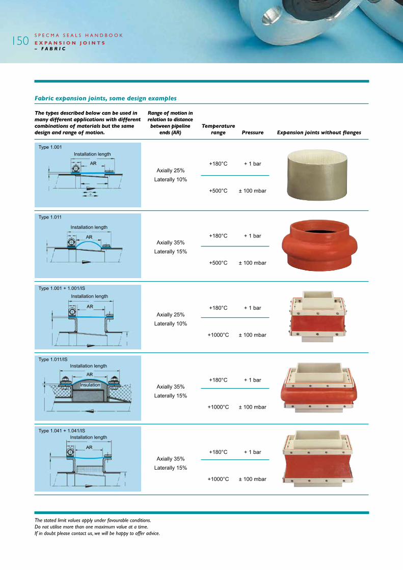
Fabric expansion joints, some design examples
The types described below can be used in many different applications with different combinations of materials but the same design and range of motion.
Range of motion in relation to distance between pipeline
ends (AR)
+180°C
+500°C
+180°C
+500°C
+180°C
+1000°C
+180°C
+1000°C
+180°C
+1000°C
Axially 25%Laterally 10%
Axially 35%Laterally 15%
Axially 25%Laterally 10%
Axially 35%Laterally 15%
Axially 35%Laterally 15%
Expansion joints without flangesTemperature
range Pressure
+ 1 bar
± 100 mbar
+ 1 bar
± 100 mbar
+ 1 bar
± 100 mbar
+ 1 bar
± 100 mbar
+ 1 bar
± 100 mbar
150
Installation length
Installation length
Installation length
Installation length
Installation length
Insulation
Type 1.001
Type 1.011
Type 1.001 + 1.001/IS
Type 1.011/IS
Type 1.041 + 1.041/IS

Fabric expansion joints, some design examples
The types described below can be used in many different applications with different combinations of materials but the same design and range of motion.
Range of motion in relation to
distance between pipeline ends (EH) Expansion joints with flanges
Temperature range Pressure
S P E C M A S E A L S H A N D B O O K
E X P A N S I O N J O I N T S – F A B R I C
+180°C
+500°C
+180°C
+500°C
+180°C
+500°C
+180°C
+250°C
+180°C
+500°C
Axially 25%Laterally 10%
Axially 35%Laterally 15%
Axially 70%Laterally 30%
Axially 25%Laterally 10%
Axially 70%Laterally 30%
+ 1 bar
± 100 mbar
+ 3 bar
± 100 mbar
- 0.5 bar
± 100 mbar
+ 1 bar
± 100 mbar
+ 5 bar
± 100 mbar
151
Installation length = EHType 1.351
Type 1.301
Type 1.251
Type 1.211
Type 1.201
Installation length = EH
Installation length = EH
Installation length = EH
Installation length = EH

Fabric expansion joints, some design examples
The types described below can be used in many different applications with different combinations of materials but the same design and range of motion.
Range of motion in relation to distance between pipeline
ends (AR/EH)
+180°C
+400°C
+180°C
+400°C
+180°C
+500°C
+180°C
+500°C
+180°C
+500°C
Axially 70%Laterally 30%
Axially 60%Laterally 30%
Axially 70%Laterally 20%
Axially 100%Laterally 10%
Axially 70%Laterally 10%
+ 1 bar
± 200 mbar
+ 1 bar
± 200 mbar
- 0.5 bar
± 100 mbar
+ 3 bar
± 100 mbar
+ 3 bar
± 100 mbar
Expansion joints for large movementsTemperature
range Pressure
S P E C M A S E A L S H A N D B O O K
E X P A N S I O N J O I N T S – F A B R I C
The stated limit values apply under favourable conditions. Do not utilise more than one maximum value at a time. If in doubt please contact us, we will be happy to offer advice.
152
Installation length
Type 1.031/2
Type 1.231/3
Type 3.251
Type 1.422
Type 2.422
Installation length = EH
Installation length = EH
Installation length = EH
Installation length = EH

Fabric expansion joints, some design examples
The types described below can be used in many different applications with different combinations of materials but the same design and range of motion.
Range of motion in relation to
distance between pipeline ends (AR)
+180°C
+500°C
+180°C
+500°C
+180°C
+250°C
+180°C
+500°C
+180°C
+500°C
Axially 80%Laterally 20%
Axially 50%Laterally 20%
Axially 30%Laterally 10%
Axially 25%Laterally 10%
Axially 80%Laterally 20%
Special expansion jointsTemperature
range Pressure
S P E C M A S E A L S H A N D B O O K
E X P A N S I O N J O I N T S – F A B R I C
+ 1 bar
± 100 mbar
+ 1 bar
± 100 mbar
+ 1 bar
± 200 mbar
+ 1 bar
± 100 mbar
+ 0.5 bar
± 100 mbar
153
Installation length
Installation length = EH
Installation length = EH
Installation length
Installation length
Type 1.012
Type 1.022
Type 1.421
Type 1.101
Type 1.072

S P E C M A S E A L S H A N D B O O K
E X P A N S I O N J O I N T S – F A B R I C
The stated limit values apply under favourable conditions. Do not utilise more than one maximum value at a time. If in doubt please contact us, we will be happy to offer advice.
Temperature range Chemical resistance
continously max °C °C acids alkalis solvents Remarks
Fabric Polyester +150 +180 o o o high tensile strength, good wear resistance
novaTEXaramidfibre +250 +380 + o o veryhightensilestrength,highresistancetothermalradiation
novaTEXGOLD +450 +600 + o o veryhightensilestrength,highresistancetothermalradiation
isoGLAS +450 +550 + + + good insulation properties
isoGLAS special +450 +650 + + + good insulation properties
isoGLAS with chromium steel wire reinforcement +450 +650 + + + good insulation properties
isoTHERM 800 +700 +800 ++ + + highertensilestrengththanglassfibre
isoTHERM 1000 +850 +1000 ++ + + highertensilestrengththanglassfibreathightemperatures
Silicate +1000 +1350 ++ + + excellent properties at high temperatures
Wire mesh +800 +1280 + + ++ enclosestheinsulationmaterials,vacuum
Laminate materials Multilam 300 PTFE laminate +260 +300 ++ ++ ++ for foods and chemicals
Texlam2000PTFE-coatedglassfibrefabric +260 +300 ++ ++ ++ excellent chemical resistance
Fabric impregnation and surface coating Chloroprenerubber(CR) +90 +100 o o o resistant to weather and ageing
Hypalonrubber(CSM) +100 +120 ++ o o acid-resistant
Ethylenepropylenerubber(EPDM) +120 +150 + o o resistant to steam and acid
Siliconerubber(Si) +180 +220 + + o resistanttothermalradiation,easytohandle,weather-resistant and capable of withstanding low temperatures
Fluorinerubber(FKM) +200 +300 ++ + o verysuitablefordesulphurisationplants
PTFE +260 +290 ++ ++ ++ excellent chemical resistance
Foils Chloroprenerubber(CR) +90 +100 o o o resistant to weather and ageing
Hypalonrubber(CSM) +100 +120 ++ o o acid-resistant
Ethylenepropylenerubber(EPDM) +120 +150 + o o resistant to steam and acid
Siliconerubber(Si) +180 +220 + + o resistanttothermalradiation,easytohandle,weather-resistant and capable of withstanding low temperatures
Fluorinerubber(FKM) +200 +300 ++ + o verysuitablefordesulphurisationplants
PTFE +260 +280 ++ ++ ++ excellent chemical resistance
PTFE-impregnatedglassfibre +260 +290 ++ ++ ++ excellent chemical resistance
Lead +300 +300 + - + high resistance to thermal radiation
Aluminium +650 +650 o o + reflectsthermalradiation
Stainless steel +600 +800 ++ + ++ acid-resistant and high temperatures
Insulation materials Ceramic wool +1100 +1300 ++ + + insulation for high temperatures
Mineral wool +550 +750 + + + for insulation and dust protection
Rubber for desulphurisation plantsFluorinerubberwithreinforcement purifiedgasorgascontainingparticleseveninwasteincinerationplants ofstainlesssteel1.4539(AISI904L) +200 +300 ++ + o
Fluorinerubberwithreinforcement purifiedgasorgascontainingparticleseveninwasteincinerationplants ofnovaTEXaramidfibrefabric +200 +300 ++ + o
Fluorinerubberwithreinforcement purifiedgasorgascontainingparticleseveninwasteincinerationplants of“Glass-Kevlar900”fabric 200 300 ++ + o
Fluorinerubberwithreinforcement purifiedgasorgascontainingparticleseveninwasteincinerationplants ofglassfibrefabric 200 300 ++ + o
Materials, temperature and media: Media resistance for the most common materials in fabric expansion joints.
Key: ++ = very good + = good o = limited - = not suitable
154

S P E C M A S E A L S H A N D B O O K
E X P A N S I O N J O I N T S – F A B R I C
Installation for open design expansion joints:In many cases, e.g. when expansion joints have insulation or are provided with deflector plates or due to special installation conditions, expansion joints are supplied in an open version for final assembly on site. The joints for each component layer of material are prepared in advance for this process. If the installation instructions supplied with each expansion joint are followed carefully, this work can be done by your own staff, or with the assistance of Specma Seals service staff.
Installation of an open design expansion joint begins by placing the expansion joint around the pipe or flue gas duct. Place the joint upwards if the pipe/duct runs horizontally. Stretch the expansion joint to smooth out any irregularities. Start installation by overlapping the first layer, then continue with the subsequent layers. All layers consisting of fabric or film are bonded using the adhesive supplied when the operating temperature of the medium does not exceed +250°C. At temperatures above this, a needle and thread are used to join the layers together. A special heat-resistant thread is supplied in such cases. Only the outermost layer inside the outermost sealing layer is sealed with adhesive in these cases.
It is very important to follow the installation steps below so that the joint will function correctly. Depending on which material is used in the outermost sealing layer, the correct adhesive or rubber solution must be used.
Once the expansion joint is installed correctly, the fastening elements must be fitted and then tightened to the same tightening torque. The joint should be retightened once the system has reached operating temperature.
1. Installation begins by placing the innermost layer on the pipe/duct with an overlap joint.
2. Bond or sew together the overlap joint. At temperatures below +250°C, adhesive is used. At temperatures above that, the joint is sewn together.
3. The second layer of fabric is spliced edge-to-edge.
4. The final layer of fabric is overlapped and secured with either adhesive or a needle and thread.
5. Joining the layer of sealing foil requires particular care. First, place the two ends together, “back-to-back”.
6. The long end is folded over the short one. Then roll both together until all the excess material is folded in.
7. Depending on the design of the expansion joint, there will be one to two further layers of fabric outside the layer of sealing foil.
8. This/these layer/layers is/are sealed as per section 2 and section 3 respectively.
9. The final layer is sealed using the same material as the outer sealing layer of the outermost layer of fabric, e.g. silicone rubber.
155

S P E C M A S E A L S H A N D B O O K
E X P A N S I O N J O I N T S – F A B R I C
The stated limit values apply under favourable conditions. Do not utilise more than one maximum value at a time. If in doubt please contact us, we will be happy to offer advice.
Frenzelit Elastomer expansion joint:Elastomer expansion joints are made primarily for use in desulphurisation plants with high concentrations of sulphuric acid and sulphur dioxide. They can also be used in chemical applications where fluorine rubber is resistant to the media.
Some examples of elastomer expansion joints:
This expansion joint is made of reinforced fluorine rubber which is able to withstand corrosive substances at temperatures of up to 200°C. The material thickness varies between 3.5 and 6 mm depending on the pressure and movement.
Reinforcement of aramid fibre, glass fibre or stainless steel is vulcanised into the rubber layer so that the expansion joint is capable of withstanding extreme operating conditions.
The questionnaire can also be used for this type of expansion joint.
Expansion joints without flanges
Range of motion in relation to distance between pipeline ends (AR)
Axially 25% Laterally 10%
Expansion joints with flanges
Range of motion in relation to distance between pipeline ends (EH)
Axially 25% Laterally 10%
Expansion joints with bulb and flanges
Range of motion in relation to distance between pipeline ends (EH)
Axially 35% Laterally 15%
156
An expansion joint can easily be manufactured on site using expansion joint fabric sold by the metre.
This fabric is available in a range of qualities suitable for various applications and operating conditions (see page 154). For a quotation, please use the questionnaire on page 226.
Self-manufacture of expansion joints:
Installation length
Type 1.001
Type 1.201
Type 1.211
Installation length = EH
Installation length = EH

Standard types:Axialexpansionjointwithflanges
Axial expansion joint with welded ends
Pressure-balanced axial expansion joint
Pressure-balanced axial expansion joint with tube elbow
Universalexpansionjointwithtwosetsofbellows
Pressure-balanceduniversalexpansionjoint
Pressure-balanceduniversalexpansionjoint with tube elbow
Togglelinkexpansionjoint
S P E C M A S E A L S H A N D B O O K
E X P A N S I O N J O I N T S – S T E E L
Steel expansion joints
Material description:Specma steel expansion joints are supplied in a range of different versions, with or without flange connections. One thing they all have in common is the fact that the bellow segment is made from acidproof stainless steel in one or more layers. The number of layers is dependent upon the relevant operating conditions. Flanges and welded ends can be supplied in various materials depending on the application. Expansion joints can also be provided with built-in tie bars for applications with major dynamic stresses.
Properties:Steel expansion joints are used primarily to compensate for thermal movements and vibration in pipe systems. A steel expansion joint is used to absorb the movements in the pipe systems, thereby reducing the risk of pipe rupture and stresses. Can also compensate for minor misalignment when installing pipe systems.
Applications:Common areas of application are applications at high temperatures with limited pressure where rubber expansion joints are not suitable, e.g. steam and hot
Technical data:
Temperature range: -270°C to +1300°C
Max. internal pressure: max. 500 bar
Dimensions: up to DN 2000
water pipes, process and district heating systems, exhaust pipes, turbines etc.
Anchoring:In a piping system containing expansion joints, it is important to properly anchor and guide the pipes to insure the expansion joints absorb the motion for which they were designed.
Inadequate anchoring and/or improper guiding can cause stresses that reduce the life span of an expansion joint. When an expansion joint is pressurized, internal thrust forces are created which react on the system and anchors. This force is due to internal pressure acting on the effective area of the bellows element in the expansion joint.
This force created by pressure must be absorbed in the piping system by anchors to prevent the bellows element from extending. Anchors in a piping system are generally of two kinds, main anchors to absorb full pressure thrust forces generated by the expansion joint, and intermediate anchors to absorb forces generated by the expansion joint bellows spring forces.
Examples of main anchors and intermediate anchors are shown in the diagram below. It should be noted that pipe guides are intended to guide the pipes in a system and not support the weight of the pipes and media conveyed through them.
Manufacturing:Specma steel expansion joints are manufactured and dimensioned according to customers' individual installation criteria. These expansion joints are supplied with either fixed or rotatable flanges for installation in systems with counter flanges where simple installation and removal are required. Alternatively, these expansion joints can be supplied with welded ends for permanent welding into pipe systems. Ask for a special catalogue for more detailed information on the Specma range of steel expansion joints.
To achieve the best possible results in each case, it is important to to carefully complete the questionnaire for steel expansion joints which can be found in the “Questionnaire” section and on our website at www.specmaseals.se/Products.
157