Sealed and Insulated Fiber Board Ducts
18
Sealed and Insulated Fiber Board Ducts Last Updated: 08/21/2017 Scope Air seal and insulate fiber board ducts. Design a compact duct layout with short straight runs and minimal bends. Design the home to include ducts within conditioned space if possible. (The DOE Zero Energy Ready Home program requires that heating/cooling system supply ducts be installed within the conditioned space of the home.) Fabricate and install the fiber board ducts. To seal seams, use outward-clinched staples and UL-181A-approved metal tape that is heat activated or pressure sensitive or use mastic and fiber mesh tape. Use screws to secure connections to sheet metal collars, duct boots, or trunk lines. Wipe ducts to ensure they are clean and dry, then seal seams and joints with mastic or UL- 181-approved metal tape. Ensure that all duct connections and seams are air sealed, regardless of whether components are located in conditioned or unconditioned space. Insulate all supply and return ducts located in unconditioned space. Meet code or program minimum R-value requirements. See the Compliance tab for R-value minimum requirements specified in the IRC, IECC, DOE Zero Energy Ready Home program, and ENERGY STAR criteria. Consider insulating all metal ductwork located in conditioned space, including supply and return ducts, duct boots, and exhaust ducts, to minimize condensation. See the Compliance Tab for related codes and standards requirements, and criteria to meet national programs such as DOE’s Zero Energy Ready Home program, ENERGY STAR Certified Homes, and Indoor airPLUS. Air seal and insulate flex ducts
Transcript of Sealed and Insulated Fiber Board Ducts

Sealed and Insulated Fiber Board Ducts
Last Updated: 08/21/2017
Scope
Air seal and insulate fiber board ducts.
Design a compact duct layout with short straight runs and minimal bends. Design the home to include ducts within conditioned space if possible. (The DOE Zero Energy Ready Home program requires that heating/cooling system supply ducts be installed within the conditioned space of the home.)
Fabricate and install the fiber board ducts. To seal seams, use outward-clinched staples and UL-181A-approved metal tape that is heat activated or pressure sensitive or use mastic and fiber mesh tape. Use screws to secure connections to sheet metal collars, duct boots, or trunk lines. Wipe ducts to ensure they are clean and dry, then seal seams and joints with mastic or UL-181-approved metal tape.
Ensure that all duct connections and seams are air sealed, regardless of whether components are located in conditioned or unconditioned space.
Insulate all supply and return ducts located in unconditioned space. Meet code or program minimum R-value requirements. See the Compliance tab for R-value minimum requirements specified in the IRC, IECC, DOE Zero Energy Ready Home program, and ENERGY STAR criteria.
Consider insulating all metal ductwork located in conditioned space, including supply and return ducts, duct boots, and exhaust ducts, to minimize condensation.
See the Compliance Tab for related codes and standards requirements, and criteria to meet national programs such as DOE’s Zero Energy Ready Home program, ENERGY STAR Certified Homes, and Indoor airPLUS.
Air seal and insulate flex ducts

DescriptionFiber board used for the fabrication of supply and return air duct work for HVAC systems is constructed of resin-bonded strands of glass fibers (e.g., fiberglass) that are formed into flat sheets, typically 4 foot wide by 10 foot long or 4 foot wide by 8 foot long; it typically comes in thicknesses of 1, 1.5, and 2 inches. The exterior surface of the sheet is covered with a reinforced foil laminate air/vapor barrier. The interior surface that is in contact with air flow is not as smooth as metal because it consists of bare bonded fiberglass (Figure 1). Fibrous glass duct boards are available with a durable, hard interior surface treatment to prevent eroding of the bonded fiberglass; however, this type of fiber board is very expensive. Many brands of fiber board are also available with an antimicrobial coating on the interior surface. Fiber board ducting can be used for heating and cooling ducts; it is not recommended for ventilation ducts, especially in humid climates.
Figure 1 - Fiberglass duct board typically comes in sheets 4 foot wide by 10 foot long.
One advantage of fiber board is the fact that it is inherently insulating; the fibrous glass board carries an R-value of 4.3 per inch, so thicknesses of 1, 1.5, and 2 inches yield R-values of 4.3, 6.5, and 8.7. The product itself is air tight so the air tightness of the overall fiber board duct system is dependent on the care with which the sections are fabricated and the joints and seams are cut and sealed. The durability of the fiber board is also contingent on the care taken in constructing the ducts. The fabricator must be careful to not fracture the bonded fibers. A crack in the bonded fiberglass may not be noticed if it is concealed by the reinforced foil laminate but, over time, it can lead to the erosion of the glass fibers, creating a durability issue and compromising the insulation value of the duct.
Fiber board ducts have been tested for safe use at velocities up to 5,000 feet per minute and temperatures up to 250°F (121°C) (NAIMA 2010).
HVAC contractors who use fiber board ducts typically purchase duct board sheets by the carton (each carton contains 5 or 6 sheets) and fabricate the ducts themselves in the shop or on site. The sheets are available with straight edges or with factory-cut male-female shiplapped edges along each of the long sides (Figure 2). The sheets are cut and folded to the designed duct dimensions by the fabricator. Each 4-foot section is fitted together using the shiplapped ends (Figure 3).
Figure 2 - Fiber board sheets are available with factory-cut male/female shiplapped ends along the long side of each sheet.

Figure 3 - A length of rectangular HVAC duct assembled using duct board. Note the shiplapped end for fitting to the next section of duct. The gray interior on this fiber board indicates an antimicrobial coating.
Fiber board ducts are fabricated using either specially designed hand tools or grooving and closure machines. The duct sections are assembled by matching factory or field-cut shiplapped male and female ends. The shiplapping ensures close-fitting, smooth joints when duct sections are joined together. Duct fittings such as tees, offsets, elbows, and transitions are also fabricated from these sections or from flat duct board.
Typical tools used to fabricate fiber board duct systems in the field include a yardstick or tape measure, straight edge, duct board knife, marking pen, and edge-cutting tools. If hand cutting, the tools used should be fiber board cutting tools specifically designed for the intended cuts, to ensure a consistent connection. The cutting tools come in different sizes depending on the thickness of the fiber board being used: 1 inch, 1.5 inch, or 2 inch. The tool manufacturers color-code the tools red, orange, or grey to identify which type of edge or end cut the tool will make: the red tool cuts a V-shaped groove, the orange tool cuts a shiplap, and the grey tool makes a final or female shiplap (see Figure 4). When forming the inside corners of the duct, the fabricator can use either the V-groove or modified shiplap method. Some manufacturers recommend the modified shiplap method as providing a more stable corner (Knauf 2006). Many installers prefer the V-groove method for straight duct sections because it is much faster to assemble. They use the shiplap method for assembling and connecting fittings, branches, and other modifications.
Fiber board duct can also be machine fabricated in the shop using a grooving machine. A grooving machine can be set up to provide the same kinds of cuts as the hand tools, with the advantage that it can make multiple cuts at one time with consistency and precision.
In addition to the seam and edge cuts, the fiberglass is cut away 1.5 inches from the edge on one side leaving a foil flap that will serve to cover the finished seam. After the cuts are made, the fiber board is folded together to form a rectangle, and the flap is pulled taut over the opposite edge, then stapled in place using out-clinching staples. All seams and joints are sealed with UL-181A heat-sealing tape, pressure-sensitive tape, or mastic and fiber mesh tape.
When connecting fiber duct board sections to sheet metal components such as equipment flanges, fasteners such as sheet metal screws and washers are used to carry the mechanical load. Mastic and glass fiber fabric are typically used to air seal the connections at these points. However, approved pressure-sensitive aluminum foil tape or heat-activated aluminum foil/scrim tape may be used to seal the fiber board to the sheet metal when the operating pressure is less than 1 in. w.g. (250 Pa) and when sheet metal surfaces are cleaned in accordance with tape manufacturers’ instructions. Closure details may be found in Section IV of the North American Insulation Manufacturers Association Fibrous Glass Duct Construction Standard (NAIMA 2010).
Figure 4 - With a marker, a knife, measuring tape, a ruler, and a straight edge, plus edge-cutting tools (which are color-coded red, orange, and grey by the manufacturer to indicate the cut design), the installer can cut and fabricate a complete fiber board duct

system.
Example instructions for the field fabrication and assembly of one section of fiber board duct are provided below. Detailed instructions and dimensions for hand cutting and machine cutting fiber board ducts in several configurations are available on line from insulation manufacturers such as Knauf and Johns Manville and from the North American Insulation Manufacturers Association.
How to Field Fabricate a Fiber Board Duct with Inside Dimensions of 14x6 Inches
1. Lay out a piece of 10x4 foot piece of fiber board, 1.5 inches thick, foil side down.
2. Starting at the left edge, mark out center lines for each corner, plus the line for the start of the stapling flap (on the left). Because you will only need 52.5 inches of length to make a duct with inside dimensions of 14x6 inches, you could mark up and cut the 120-inch fiber board to get two 52.5-inch pieces with 15 inches left over.
3. On the right edge of the board (opposite the end that has the stapling flap), cut the closure joint rabbet with a gray (female shiplap) tool. Use fiber board cutting tools specifically designed for the intended cut and for the thickness of fiber board you are using. Know your tools - cutting tools have a lip where the tool rests against the straight edge to cut a straight line. The distance from the lip to the cutting blade must be taken into account when centering the blade for the cut and this distance varies among tool brands.
4. Use a red V-groove tool to cut the grooves on the first three centerlines for the corner folds.
5. Prepare the stapling flap by making a perpendicular knife cut through the insulation 1.5 inches in from the end, taking care not to cut the foil facing. Then, strip the fiberglass insulation from the facing.
Figure 5 - The red cutting tool is used to cut a "V-groove" in the fiber board allowing each corner of the assembled duct to form a 90-degree bend, the gray tool is used to cut a shiplap joint at one edge, and the duct knife is used to trim and clean the fiberglass from the
foil at the opposite edge so it can be used as a flap to cover the seam when the duct is formed.
6. Fold the fiber board to assemble the duct section, making sure that the corners meet and fold correctly for a snug fit. Be sure to properly seat the flush edge in the rabbet cut at the closure joint.
7. To staple the seam, pull the flap taught over the opposite edge and, while holding the seam closed, slightly flatten the duct (about 30° beyond square). Staple the seam using out-clinching staples, starting at the center and working out toward each end of the seam, stapling one-half inch in from the edge at 2-inch intervals.
8. Connect this section to other sections, making sure the male and female shiplapped ends of each section are firmly seated. Smooth the stapling flap over the adjoining section and staple at 2-inch intervals.
9. Seal all longitudinal and circumferential joints using one of three approved methods:
Seal the seams with UL-181A-H heat-activated aluminum foil/scrim tape. Center the tape strip over the edge of the stapling flap, press down, and heat seal following the tape manufacturers’ instructions.
Seal the seams with UL-181A-P pressure-sensitive foil tape. Use tape that is at least 1 inch wider than the thickness of the fiber board. Center the tape over the edge of the stapling flap. Press down and rub in carefully using a squeegee or similar tool until the scrim pattern from the duct board facing shows through the tape. Heat seal if the temperature is below 40°F (4°C).
Seal the seams with UL-181A mastic and fiber mesh tape. Brush on a 4-inch-wide coating of mastic over the stapled flap. Embed a strip of 3-inch-wide open-mesh glass fiber fabric tape in the mastic. Apply an additional coat of mastic over the tape to cover and fill in the mesh.
10. Where sheet metal connections are made with the fiber board duct, connect the fiberboard to the metal with flat head sheet metal screws that are one-half inch longer than the thickness of the fiber board and use 1-inch outer-diameter washers. Seal the metal-fiber board seams with mastic or approved tapes after cleaning the sheet metal surfaces of any oily residue per the tape

manufacturers’ instructions.
Figure 6 - To assemble and seal the fiber board ducts, use outward-clinched staples, and UL-181A approved heat-activated or pressure-sensitive tape or mastic and fiber mesh tape.

Ensuring SuccessAfter ducts are installed and before drywall is installed, the duct system should be visually inspected by a HERS rater to ensure that all connections are properly fastened and sealed, preferably with mastic. Locations to inspect include the main supply trunk to branch connections, at the duct boots, duct splices, the return box to the return ducts, jump duct connections, and exhaust fan and ERV/HRV connections. HVAC ducts should be tested for air leakage and proper air flow with a duct blaster test. This test should be done before drywalling when any air leaks can still be accessed and sealed. Ducts should be insulated along the length including at connections, and the insulation should not be compressed by tight strapping, by framing members, or by excessive bending. The insulation should be a minimum of R-8 for all supply ducts and at least R-6 for all return ducts.

ClimateNo climate specific information applies.

Training
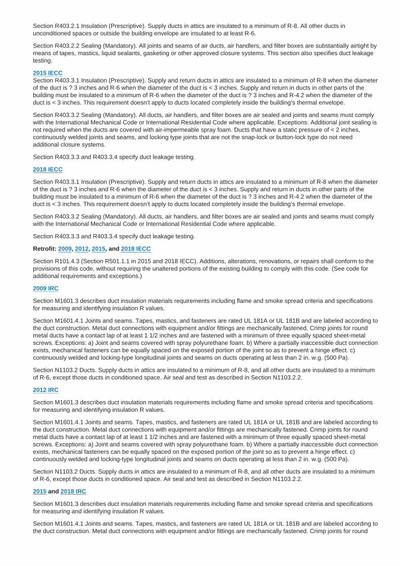
Right and Wrong Images
Display Image: ES_HVAC_QIRC_3.1_PG44_58b_102811.jpg
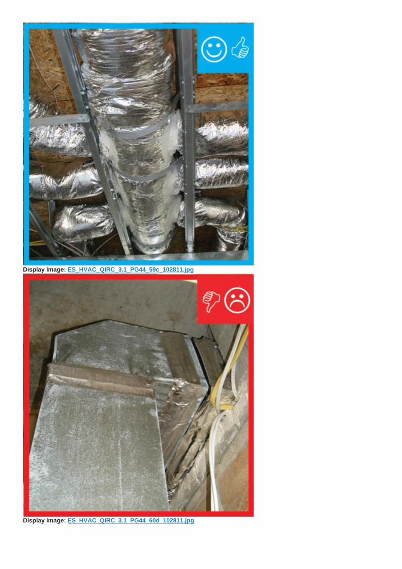
Display Image: ES_HVAC_QIRC_3.1_PG44_59c_102811.jpg
Display Image: ES_HVAC_QIRC_3.1_PG44_60d_102811.jpg

Display Image: ES_HVAC_QIRC_3.1_PG44_61e_102811.jpg
Display Image: ES_HVAC_QIRC_3.1_PG44_62f_102811.jpg

Display Image: ES_HVAC_QIRC_3.1_PG44_63g_102811.jpg
Display Image: ES_HVAC_QIRC_3.1_PG44_64h_102811.jpg

Display Image: ES_HVAC_QIRC_3.1_PG44_65i_102811.jpg
Display Image: Unsealed fiberboard duct_UWLI_2-7-19.jpg

CADNone Available

ComplianceThe Compliance tab contains both program and code information. Code language is excerpted and summarized below. For exact code language, refer to the applicable code, which may require purchase from the publisher. While we continually update our database, links may have changed since posting. Please contact our webmaster if you find broken links.
ENERGY STAR Certified Homes
ENERGY STAR Certified Homes (Version 3/3.1, Revision 08), Rater Field Checklist:6. Duct Quality Installation 6.3 All supply and return ducts in unconditioned space, including connections to trunk ducts, are insulated to ? R-635
35. Item 6.3 does not apply to ducts that are a part of local mechanical exhaust and exhaust-only whole-house ventilation systems. EPA recommends, but does not require, that all metal ductwork not encompassed by Section 6 (e.g., exhaust ducts, duct boots, ducts in conditioned space) also be insulated and that insulation be sealed to duct boots to prevent condensation.
Builders Responsibilities: It is the exclusive responsibility of builders to ensure that each certified home is constructed to meet these requirements. While builders are not required to maintain documentation demonstrating compliance for each individual certified home, builders are required to develop a process to ensure compliance for each certified home (e.g., incorporate these requirements into the Scope of Work for relevant sub-contractors, require the site supervisor to inspect each home for these requirements, and / or sub-contract the verification of these requirements to a Rater). In the event that the EPA determines that a certified home was constructed without meeting these requirements, the home may be decertified.
ENERGY STAR Revision 08 requirements are required for homes permitted starting 07/01/2016.
DOE Zero Energy Ready Home
Exhibit 1: Mandatory Requirements.
The duct distribution system is located within the home’s thermal and air barrier boundary or optimized to achieve comparable performance.16
16 Exceptions and alternative compliance paths to locating 100% of forced-air ducts in home’s thermal and air barrier boundary are:
a. Up to 10’ of total duct length is permitted to be outside of the home’s thermal and air barrier boundary.
b. Ducts are located in an unvented attic, regardless of whether this space is conditioned with a supply register
c. Ducts are located in a vented attic with all of the following characteristics:
i. In Moist climates (Zones 1A, 2A, 3A, 4A, 5A, 6A and 7A per 2012 IECC Figure R301.1) and Marine climates (all “C” Zones per 2012 IECC Figure R301.1), minimum R-8 duct insulation with an additional minimum 1.5” of closed-cell spray foam insulation encapsulating the ducts; duct leakage to outdoors ? 3 CFM25 per 100 ft2 of conditioned floor area (in addition to meeting total duct leakage requirements from Section 4.1 of the ENERGY STAR HVAC Rater checklist); and ductwork buried under at least 2” of blown-in insulation.
ii. In Dry climates (all “B” Zones per 2012 IECC Figure R301.1), minimum R-8 duct insulation; duct leakage to outdoors ? 3 CFM25 per 100 ft2 of conditioned floor area (in addition to meeting total duct leakage requirements from Section 4.1 of the ENERGY STAR HVAC Rater checklist); and ductwork buried under at least 3.5” of blown-in insulation.Note that in either of these designs the HVAC equipment must still be located within the home’s thermal and air barrier boundary.
d. Jump ducts which do not directly deliver conditioned air from the HVAC unit may be located in attics if all joints, including boot-to-drywall, are fully air sealed with mastic or foam, and the jump duct is fully buried under the attic insulation.
e. Ducts are located within an unvented crawl space.
f. Ducts are located in a basement which is within the home’s thermal boundary.
g. Ductless HVAC system is used.
2009 IECC
Section 403.2.1 Insulation (Prescriptive). Supply ducts in attics are insulated to a minimum of R-8. All other ducts in unconditioned spaces or outside the building envelope are insulated to at least R-6.
Section 403.2.2 Sealing (Mandatory). All joints and seams of air ducts, air handlers, filter boxes, and building cavities used as return ducts are substantially airtight by means of tapes, mastics, liquid sealants, gasketing or other approved closure systems. This section also specifies duct leakage testing.
2012 IECC
Section R403.2.1 Insulation (Prescriptive). Supply ducts in attics are insulated to a minimum of R-8. All other ducts in unconditioned spaces or outside the building envelope are insulated to at least R-6.
Section R403.2.2 Sealing (Mandatory). All joints and seams of air ducts, air handlers, and filter boxes are substantially airtight by means of tapes, mastics, liquid sealants, gasketing or other approved closure systems. This section also specifies duct leakage testing.
2015 IECCSection R403.3.1 Insulation (Prescriptive). Supply and return ducts in attics are insulated to a minimum of R-8 when the diameter of the duct is ? 3 inches and R-6 when the diameter of the duct is < 3 inches. Supply and return in ducts in other parts of the building must be insulated to a minimum of R-6 when the diameter of the duct is ? 3 inches and R-4.2 when the diameter of the duct is < 3 inches. This requirement doesn’t apply to ducts located completely inside the building’s thermal envelope.
Section R403.3.2 Sealing (Mandatory). All ducts, air handlers, and filter boxes are air sealed and joints and seams must comply with the International Mechanical Code or International Residential Code where applicable. Exceptions: Additional joint sealing is not required when the ducts are covered with air-impermeable spray foam. Ducts that have a static pressure of < 2 inches, continuously welded joints and seams, and locking type joints that are not the snap-lock or button-lock type do not need additional closure systems.
Section R403.3.3 and R403.3.4 specify duct leakage testing.
2018 IECC
Section R403.3.1 Insulation (Prescriptive). Supply and return ducts in attics are insulated to a minimum of R-8 when the diameter of the duct is ? 3 inches and R-6 when the diameter of the duct is < 3 inches. Supply and return in ducts in other parts of the building must be insulated to a minimum of R-6 when the diameter of the duct is ? 3 inches and R-4.2 when the diameter of the duct is < 3 inches. This requirement doesn’t apply to ducts located completely inside the building’s thermal envelope.
Section R403.3.2 Sealing (Mandatory). All ducts, air handlers, and filter boxes are air sealed and joints and seams must comply with the International Mechanical Code or International Residential Code where applicable.
Section R403.3.3 and R403.3.4 specify duct leakage testing.
Retrofit: 2009, 2012, 2015, and 2018 IECC
Section R101.4.3 (Section R501.1.1 in 2015 and 2018 IECC). Additions, alterations, renovations, or repairs shall conform to the provisions of this code, without requiring the unaltered portions of the existing building to comply with this code. (See code for additional requirements and exceptions.)
2009 IRC
Section M1601.3 describes duct insulation materials requirements including flame and smoke spread criteria and specifications for measuring and identifying insulation R values.
Section M1601.4.1 Joints and seams. Tapes, mastics, and fasteners are rated UL 181A or UL 181B and are labeled according to the duct construction. Metal duct connections with equipment and/or fittings are mechanically fastened. Crimp joints for round metal ducts have a contact lap of at least 1 1/2 inches and are fastened with a minimum of three equally spaced sheet-metal screws. Exceptions: a) Joint and seams covered with spray polyurethane foam. b) Where a partially inaccessible duct connection exists, mechanical fasteners can be equally spaced on the exposed portion of the joint so as to prevent a hinge effect. c) continuously welded and locking-type longitudinal joints and seams on ducts operating at less than 2 in. w.g. (500 Pa).
Section N1103.2 Ducts. Supply ducts in attics are insulated to a minimum of R-8, and all other ducts are insulated to a minimum of R-6, except those ducts in conditioned space. Air seal and test as described in Section N1103.2.2.
2012 IRC
Section M1601.3 describes duct insulation materials requirements including flame and smoke spread criteria and specifications for measuring and identifying insulation R values.
Section M1601.4.1 Joints and seams. Tapes, mastics, and fasteners are rated UL 181A or UL 181B and are labeled according to the duct construction. Metal duct connections with equipment and/or fittings are mechanically fastened. Crimp joints for round metal ducts have a contact lap of at least 1 1/2 inches and are fastened with a minimum of three equally spaced sheet-metal screws. Exceptions: a) Joint and seams covered with spray polyurethane foam. b) Where a partially inaccessible duct connection exists, mechanical fasteners can be equally spaced on the exposed portion of the joint so as to prevent a hinge effect. c) continuously welded and locking-type longitudinal joints and seams on ducts operating at less than 2 in. w.g. (500 Pa).
Section N1103.2 Ducts. Supply ducts in attics are insulated to a minimum of R-8, and all other ducts are insulated to a minimum of R-6, except those ducts in conditioned space. Air seal and test as described in Section N1103.2.2.
2015 and 2018 IRC
Section M1601.3 describes duct insulation materials requirements including flame and smoke spread criteria and specifications for measuring and identifying insulation R values.
Section M1601.4.1 Joints and seams. Tapes, mastics, and fasteners are rated UL 181A or UL 181B and are labeled according to the duct construction. Metal duct connections with equipment and/or fittings are mechanically fastened. Crimp joints for round
https://basc.pnnl.gov/resources/2009-irc—international-residential-code-one-and-two-family-dwellings
https://basc.pnnl.gov/resources/2012-irc—international-residential-code-one-and-two-family-dwellings

metal ducts have a contact lap of at least 1 1/2 inches and are fastened with a minimum of three equally spaced sheet-metal screws. Exceptions: a) Joint and seams covered with spray polyurethane foam. b) Where a partially inaccessible duct connection exists, mechanical fasteners can be equally spaced on the exposed portion of the joint so as to prevent a hinge effect. c) continuously welded and locking-type longitudinal joints and seams on ducts operating at less than 2 in. w.g. (500 Pa).
Section N1103.3 Ducts are insulated and tested as specified in the IECC.
Retrofit: 2009, 2012, 2015, and 2018 IRC
Section N1101.3 (Section N1107.1.1 in 2015 and 2018 IRC). Additions, alterations, renovations, or repairs shall conform to the provisions of this code, without requiring the unaltered portions of the existing building to comply with this code. (See code for additional requirements and exceptions.)
Appendix J regulates the repair, renovation, alteration, and reconstruction of existing buildings and is intended to encourage their continued safe use.
https://basc.pnnl.gov/resources/2009-irc-international-residential-code-one-and-two-family-dwellings
https://basc.pnnl.gov/resources/2012-irc-international-residential-code-one-and-two-family-dwellings

More Info.Access to some references may require purchase from the publisher. While we continually update our database, links may have changed since posting. Please contact our webmaster if you find broken links.
Case StudiesNone Available
References and Resources*
1. ACCA Manual D - Residential Duct SystemsAuthor(s): Air Conditioning Contractors of AmericaOrganization(s): Air Conditioning Contractors of AmericaPublication Date: December, 2013Standard outlining industry procedure for sizing residential duct systems.
2. DOE Zero Energy Ready Home National Program RequirementsAuthor(s): Department of EnergyOrganization(s): DOEPublication Date: April, 2017
Standard requirements for DOE's Zero Energy Ready Home national program certification.
3. Duct and HVAC InsulationAuthor(s): North American Insulation Manufacturers AssociationOrganization(s): North American Insulation Manufacturers AssociationPublication Date: January, 2010Information sheet with HVAC duct insulation, testing, maintenance and performance information.
4. Duct SealingAuthor(s): Building Science CorporationOrganization(s): Building Science CorporationPublication Date: May, 2009
Brochure with details on HVAC duct air sealing.
5. ENERGY STAR Certified Homes, Version 3 (Rev. 08) National Program RequirementsAuthor(s): U.S. Environmental Protection AgencyOrganization(s): EPAPublication Date: December, 2015
Webpage with links to Document outlining the program requirements for ENERGY STAR Certified Homes, Version 3 and 3.1 (Rev. 08).
6. Fiber Glass Duct Board Fabrication InstructionsAuthor(s): Johns ManvilleOrganization(s): Johns ManvillePublication Date: January, 2008Information sheet providing detail about hand fabrication of a one-piece straight duct from a 48" x 120" x 1" thick (1.22 m x 3.05 m x 25 mm) sheet where the total inside duct dimensions equals 112" (2.84 m) or less.
7. Knauf Insulation Air Duct Fabrication Manual for 1", 1-1/2", and 2"Author(s): KnaufOrganization(s): KnaufWebsite providing information about Knauf Insulation.
8. Measure Guideline: Sealing and Insulating Ducts in Existing HomesAuthor(s): Aldrich, PuttaguntaOrganization(s): CARB, National Renewable Energy Laboratory, Steven Winter Associates, SWAPublication Date: December, 2011
Report descibing the sealing and insulating of HVAC duct systems in new and existing homes.
*Publication dates are shown for formal documents. Dates are not shown for non-dated media. Access dates for referenced, non-dated media, such as web sites, are shown in the measure guide text.
Contributors to this GuideThe following authors and organizations contributed to the content in this Guide.