Deliverable 3.5 Functional links between sea-bed habitats ...

talk outline
� sea bed network deployment issues;
� energy distribution seabed network issues;
� data transmission seabed network;� data transmission seabed network;

seabed network decisional process
specification from physicsspecification from physics
deployment
feasibility
no
yes
data and energy
network compatibility
no

deployment strategythe question is: what to deploy in advance?
the detection units or the seabed network?
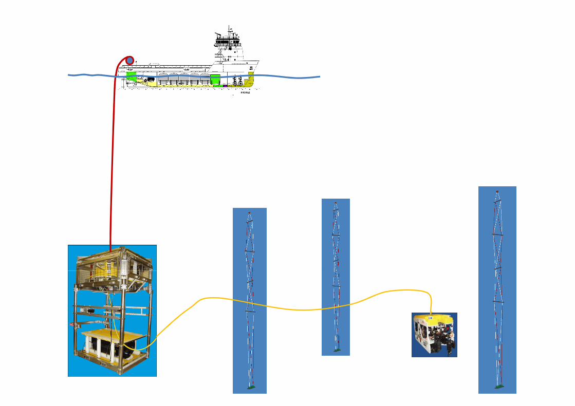

Example of SEABED NETWORK
PJB
SJB close
to a towerto a tower
tower
5
MEOC
Cable PJB-SJB
Cable SJB-tower
180 m

This proposal is based on the learned lesson and the current market availability. It strongly takes in account the deployment issues.
The proposal aims to demonstrate the feasibility of the system.
ELECTRICAL POWER SYSTEM Proposal
DESIGN INPUTS & CONSTRAINTS:
• a10kV wet mateable connector is not still tested and ready on the market
for this reason a MV Power distribution network has not been taken in account
at the moment ;
• a 375V DC distribution network has been evaluated
(375 V DC is the ALCATEL MVC output voltage);(375 V DC is the ALCATEL MVC output voltage);
• low voltage (375V DC) distribution network cannot accept huge cable (both in cross section and length) due to deployment issues;
• number of detection unit considered: 90 (expandable to 130);
• detection unit electrical load less than 300W;
• total power consumption: 27kW;

ELECTRICAL SUBSYSTEMS:
On-shore :
• A 50 kW Power Feed Equipment with:
- Input Voltage: 400 V AC 3 phase
ELECTRICAL POWER SYSTEM Proposal
- Input Voltage: 400 V AC 3 phase
- Output Voltage: 10 kV DC
Off-shore :
• A 10kV DC Power Transmission system with sea return using :
- a single conductor cable
- earth terminations
• A Power Distribution network that includes:
- Power conversion from 10 kV to 375V using the 10 kW Alcatel Medium voltage Converters;

Primary Junction Box:
the PJB will hosts:
• Cable end and sea electrode terminations;
• the MVCs;
• a monitoring and control system;
POWER DISTRIBUTION NETWORK
• Input: 10 kV feedthrough;
• Output: 400 V wet mateable connectors.
LV Distribution network - Evaluation process:
1. a LV ring distribution network containing a certain number of SJB;
pro:
- It Is one line fault tolerant: if there is a fault in one LV line it can be isolated, and all the SJBs can be fed without anydetector loss;and all the SJBs can be fed without anydetector loss;
vs:
- a second line fault can cause, in the worst case, the loss of all the detector;
- each SJB (connectors, switches, etc.) and the ring cable has to be designed
for the total detector power, 30kW/375V=80 A. As a consequence the cable cross section must be big to contain voltage drops and joule losses;
- the SJB cannot be passive;

Low Voltage Distribution Network - Evaluation Process:
2. a LV star distribution network containing a certain number of SJBs;
pro:
• The SJB are passive
POWER DISTRIBUTION NETWORK
• The SJB and the PJB-SJB cables have to be designed for a portion of the total power. It depends on the number of SJbs for ex. with 18 SJBs (each SJB feeds 5 DU) we have 30kW/18/375V=4.4A instead
of 80 A;
vs:
• In case of a PJB-SJB line fault a portion of detector is lost (5 DU);

POWER DISTRIBUTION NETWORK
TOWER 1
...MVC
MVC
MVC
...MONITORING & CONTROL
10 kV 375 V
375 V
SJB 1
TOWER 2
TOWER 5...
...
MVC
MVC
MVC
...
CONTROL
SYSTEM
SJB 18
...
SJB 8
PJB
• The PJB will host:
- a MVC Box with 5 MVC both for redundancy and for future grown of - a MVC Box with 5 MVC both for redundancy and for future grown of
the detector (25 years life from Alcatel),
- a switch Box with a monitoring and control system that can be
recovered with an automatic recovery system independently from the MVCs box,
- output 400 V wet mateable connectors including spare connectors.
• The SJB is passive and will hosts: input and output wet mateable connectors including spare connectors, fuses.

PJB
SJB
100 Km
Tower4 x 13mm^2
x 18x5
10 KV
L max 1500 m
375 V
Tower
L max 250 m
4 x 1mm^2
POWER DISTRIBUTION NETWORK
Electro-OpticalCable
PJB
...
SJB
SJB ...
Tower
Tower
• 1 Primary Junction Box (PJB)
• 18 Secondary Junction Boxes (SJB)Power per Tower 300 W
90 Towers total power 27 kW•
• 5 Tower per SJB
• PJB-SJB: radial distribution
• SJB-tower: radial distribution
• Max distance PJB-SJB: 1500m
• Max distance SJB-tower: 300m
90 Towers total power 27 kW
Cable Loss 1 kW
Cable Loss % < 4%
Cable voltage drop% < 4%
Total Power 28 kW

Example of SEABED NETWORK
PJB
SJB close
to a towerto a tower
tower
12
MEOC
Cable PJB-SJB
Cable SJB-tower
180 m

νOne - Optical Network Proposal (1/3): SJBs
DU 1
SJB 1
ROV opticalconnector
DU 2 DU 3 spare opticalConnector 1
• Double Bus topology;
• 1 colour per DU @ 2.5 Gb/s (optionally
2 colours @ 2.5 Gb/s);
1
2 3
7+ + + -1
SJB 11x4
1
5
7+ + -4
OpticalInterlink
2 colours @ 2.5 Gb/s);
• ADD for the colours from the DUs;
• 1 colour for slow control from shore
• DROP and BROADCAST for the slow
control colour @ 2.5 Gb/s;
• 5 Main optical connectors;
• Spare wide bandwidth port is available on each Bus after the Drop node;
1x4
DU 4 DU 5
spare opticalConnector 2
Interlink cable
•on each Bus after the Drop node;
• 2 Spare “colorless” connectors available;

νOne - Optical Network Proposal (2/3): PJB
DU 1 DU 2 DU 5
Cir...
**1
1
SJB 1
PJB
• Double Ring Topology;
• Band ADD&DROP at ring node level (maximum 9 nodes per ring);
• 6 colors per SJB (5 DUs + control) over 1 sub-band;
• 54 channels spreaded over contiguous bands are used by 9
**
**
1
9
...
9
Cir
SJB 9
Cir
**SJB 10
...
SJB 1
...
10
10
Interlink
cable
contiguous bands are used by 9 SJB;
• 1+1 redundancy scheme from Shore Station to SJB;
• Spare connectors can be served by a third ring (not showed)
...
**
**Cir
SJB 10
SJB 18
...
10
18
18
...MEOC

PJB
νOne - Optical Network Proposal (3/3)
• Ring topology based on circulators: doubled offshore and onshore to achieve 100% redundancy;• 1 ring can support as many DUs as fiber bandwidth allows;• Standard 100 GHz ITU grid accommodates up to ~60 colors: 2 rings are needed to transport 90 DUs;• 4 fibers of the Main Electro Optical Cable are used to setup the 2 rings;
PJB
**
*
...
1
9...
*
*
...
...
1
9
1
9
1
9
SJB
1
SJB
9
DWDM
mux
demux
band
mux-demux
...
...
*
*
*
DU 1
DU 5
...
Impossibile v isualizzare l'immagine. La memoria
del computer potrebbe essere insufficiente per aprire l'immagine oppure l'immagine potrebbe essere danneggiata. Riavviare il computer e aprire di nuovo il file. Se v iene visualizzata di nuovo la x rossa, potrebbe essere necessario elim
Impossibile v isualizzare l'immagine. La memoria del computer potrebbe essere insufficiente per aprire l'immagine oppure l'immagine potrebbe essere danneggiata. Riavviare
il computer e aprire di nuovo il file. Se v iene visualizzata di nuovo la x rossa, potrebbe essere necessario elim
Impossibile v isualizzare
**
*
...
...
*
*
...
...
10
... ...
*
*
*
SJB
10
SJB
18
demux
Station
MEOC
10
1818
10
18
10
18
DU 86
DU 90
...
Impossibile v isualizzare
l'immagine. La memoria del computer potrebbe essere insufficiente per aprire l'immagine oppure l'immagine potrebbe essere danneggiata. Riavviare il computer e aprire di nuovo il file. Se v iene visualizzata di nuovo la x rossa, potrebbe essere necessario elim
Impossibile v isualizzare l'immagine. La memoria del computer potrebbe essere insufficiente per aprire l'immagine oppure l'immagine potrebbe essere
danneggiata. Riavviare il computer e aprire di nuovo il file. Se v iene visualizzata di nuovo la x rossa, potrebbe essere necessario elim
SHORE SUB SEA