
SE s ,rid ement ;ationa
34
ontractor SE ement s ,rid ;ationa C .om brought to you by CORE View metadata, citation and similar papers at core.ac.uk provided by NASA Technical Reports Server
Transcript of SE s ,rid ement ;ationa

ontractor
SE
ement
s ,rid
;ationa
C .om
https://ntrs.nasa.gov/search.jsp?R=19900011106 2020-03-19T22:44:43+00:00Zbrought to you by COREView metadata, citation and similar papers at core.ac.uk
provided by NASA Technical Reports Server

_ _ __ m
m
_=
_k
k
= ._-

NASA Contractor Report 4279
A 4-Node Assumed-Stress Hybrid
Shell Element With Rotational
Degrees of Freedom
Mohammad A. Aminpour
Analytical Services & Materials, Inc.
Hampton, Virginia
Prepared for
Langley Research Center
under Contract NAS1-18599
National Aeronautics andSpace Administration
Office of ManagementScientific and TechnicalInformation Division
1990

11L
v_
i
B
F
i

A 4-Node Assumed-Stress Hybrid Shell Elementwith Rotational Degrees of Freedom
M. A. AMINPOUR
Analytical Services & Materials, Inc.
Hampton, VA 23666
_r Abstract
An assumed-stress hybrid/mixed 4-node quadrilateral shell element is introduced that al-
leviates most of the deficiencies associated with such elements. The formulation of the
element is based on the assumed-stress hybrid/mixed method using the Hellinger-Reissner
variational principle. The membrane part of the element has 12 degrees of freedom in-
cluding rotational or "drilling" degrees of freedom at the nodes. The bending part of
the element also has 12 degrees of freedom. The bending part of the element uses the
Reissner-Mindlin plate theory which takes into account the transverse shear contributions.
The element formulation is derived from an 8-node isoparametric element. This process
is accomplished by assuming quadratic variations for both in-plane and out-of-plane dis-
placement fields and linear variations for both in-plane and out-of-plane rotation fields
along the edges of the element. In addition, the degrees of freedom at midside nodes are
approximated in terms of the degrees of freedom at corner nodes. During this process the
rotational degrees of freedom at the corner nodes enter into the formulation of the element.
The stress field is expressed in the element natural-coordinate system such that the element
remains invariant with respect to node numbering. The membrane part of the element is
based on a 9-parameter stress field, while the bending part of the element is based on a
13-parameter stress field. The element passes the patch test, is nearly insensitive to mesh
distortion, does not "lock", possesses the desirable invariance properties, has no spurious
modes, and for the majority of test cases used in this paper produces more accurate results
than the other elements employed herein for comparison.
Introduction
The finite element method is a powerful technique that is used to solve a variety of very
complicated problems in different fields of engineering and science. In the field of struc-
tural mechanics, the finite element method is the most widely used method for obtaining
solutions to structural analysis problems. The finite element modeling of general aerospace
shell structures usually requires the use of distorted meshes. Additional complexities arise
if the original finite element discretization is further refined through an adaptive refinement
procedures. Most of the 4-node shell elements developed in the past do not produce reliable
results for distorted meshes. The element developers are usually aware of the limitations
and pitfalls of the elements. The users, on the other hand, may not be aware of all theselimitations and make invalid uses of the these elements. It is desirable to develop simple
3-node and 4-node shell elements that are free from these limitations and pitfalls, such as
spurious zero-energy modes, locking, sensitivity to mesh distortion, invariant properties,

and most importantly produceaccurateand reliable results. The elementsthat have been
developed to date lack one or more of these characteristics. The standard 3-node and
4-node isoparametric elements are generally too stiff for most practical problems, and a
"blizzard" of these elements must be used to model even simple shell structures in order
to obtain accurate and reliable results. In order to remedy the situation, researchers have
developed many non-standard elements which have their own merits and shortcomings.
Some of these elements do not pass the patch test--a requirement for convergence to the
correct solution. Some other elements have spurious mechanisms (zero-energy deforma-
tional modes) such as the hour-glass mode, while some others do not possess the desirable
invariance properties with respect to node numbering. Furthermore, most elements are
sensitive to geometry or mesh distortion.
One way to remedy the deficiencies of the membrane elements is to include the nodal ro-
tational or "drilling" degrees of freedom in the element formulation. In early attempts,
these rotational degrees of freedom were used in cubic displacement functions. However,
Irons and Ahmad demonstrated that this concept had serious deficiencies[l]. The elements
formed in such a manner force the shearing strain to be zero at the nodes and do not pass
the patch test, which could produce serious error in some structural analysis problems.
Recently several researchers have used these rotational degrees of freedom in quadratic
displacement functions with more success[2-5]. This latter method is constructed in the
following way. First, the element is internally assumed to be an 8-node (4 corner nodes
and 4 mldside nodes) isoparametric element with 16 degrees of freedom and the stiffness
matrix associated with this "internal" element is calculated. Then, this stiffness matrix is
condensed to that of a 4-node element with 12 degrees of freedom by associating the dis-
placement degrees of freedom at the mldside nodes with the displacement and rotational
degrees of freedom at the corner nodes. MacNeal[4] has used this approach to develop
4-node displacement-based membrane elements with selective reduced-order integration.
Yunus et al.[5] have also used this method to develop assumed-stress hybrid/mixed mem-brane elements.
In this paper, this method is extended to the plate problem as well as the membrane
problem to develop a 4-node assumed-stress hybrid/mixed quadrilateral shell element with
24 degrees of freedom. The formulation is based on the Hellinger-Reissner variational
principle. The =element formulation is derived from an S-node isoparametric shell element
with 40 degrees of freedom by eliminating the degrees of freedomatltia_ mldside _nodes
at the expense of adding the rotational degrees of fregd0m to the corner nodes. This
process is acc0mplished by assuming quadrati-cvar]ations for both in-piane and out-of-
plane boundary displacements and linear variations for both in-plane and out-of-plane
boundary rotations along the edges of the element and evaluating these functions at the
midside locations. These mldside values are then used to condense the stiffness matrix of
the 8-node element to that of the 4-node element. As a result, the rotational degrees of
freedom at the corner nodes enter into the formulation.
The membrane part of the element has 12 degrees of freedom, thre_pf which account
for the rigid body modes. Therefore, a minimum of 9 independent stress parameters are
needed to avoid rank deficiency for the membrane part. The bending part of the element
2
alsohas12degreesof freedom, threeof which accountfor the rigid body modes. Therefore,
a minimum of 9 independent stress parameters are also needed to avoid rank deficiency for
the bending part. The membrane stress field is represented with 9 independent parameters.
The bending stress field, on the other hand, is represented with 13 independent parameters
which was derived in references [6-8] through an asymptotic power-series expansion of
stresses in the thickness direction. This 13 parameter selection of stresses for the bending
part is less sensitive to geometry or mesh distortion than a 9 parameter selection obtained
from a degenerate solid model[9].
Evolution of Hybrid Method
The classical assumed-stress hybrid formulation of Plan[10] is based on the principle of
minimum complementary energy. The displacements are described only along the element
boundary, and an equilibrating stress field is described over the domain of the element.
It was later recognized that the same method may be derived from the Hellinger-Reissner
principle[ll-13]. However, in the Hellinger-Reissner principle the stress field is not required
to satisfy the equilibrium equations a priori, while the displacement field must be described
over the domain of the element and not just along the boundaries. The stress field would
then satisfy the equilibrium equations only in a variational sense. Therefore, the stress field
may be described in the natural-coordinate system of the element which would make the
element less sensitive to mesh distortion, and a proper selection of the stress field would
make the element invariant with respect to node numbering. For example, if the node
numbering is changed from 1-2-3-4 to 2-3-4-1, then the natural coordinate of the element
would rotate by 90 °. Therefore, a selection of stresses that is invariant under a 900 rotation
would make the element invariant. Because of these desirable attributes, researchers have
developed assumed-stress hybrid/mixed elements using the Hellinger-Reissner principle.
In this study, the Hellinger-Reissner principle is used to develop a 4-node shell element,
which includes the rotational degrees of freedom in the membrane part of the element for-
mulation. The details of the assumed-stress hybrid/mixed formulation using the Hellinger-
Reissner principle has been extensively discussed in the literature (e.g:, see references [11-
13]), and only a brief outline is given herein for completeness. The variational functional
is given as
II=-_l/vcrTDordV+/v_rTf.[u]dV-/s, uTtodS (1)
where D is the compliance matrix of the material, o" is the stress array, u is the displacement
array, to is the prescribed traction array, matrix/: is a differential operator which produces
a strain field when operated on the displacement field, V is the domain of the element,
and St is the part of the boundary where to is specified. The assumed-stress hybrid/mixed
formulation is based on assuming a stress field in the interior of the element as
(2)
and assuming the displacement field as
u=Nq (3)
3

where the matrices P and N consist of the appropriate interpolating functions for stresses
and displacements, respectively, and the vectors/3 and q are the unknown stress parameters
and nodal displacements and rotations, respectively.
The expressions for stresses in equation (2) and displacements in equation (3) are substi-
tuted into the functional II of equation (1) and the variation of the functional with respect
to the element internal unknowns/3 are set to zero. This stationary condition gives
/3 = H-1Tq (4)
where/,
H = Jv pTDPdV (5)
T = Iv pTL[N]dV (6)
The substitution of the expression for/3 in equation (4) into the functional II of equation
(1) and a subsequent variation of the functional with respect to the global unknowns q
yields
Kq = F (7)
where the stiffness matrix K is given by
K = TTH-1T (8)
and the generalized force vector F by
F = Is NTt°dSt
(9)
...... Eiement Formuiation
Midside Displacement Approximation
As discussed earlier, the stiffness matrix for the present 4-node element is obtained from
the stiffness matrix associated with the "internal" 8-node element shown in Figure i. This
process is accomplished by associating the degrees of freedom at midside nodes with the
degrees of freedom at corner nodes by expressing the displacement components along each
edge of the element as quadratic functions in terms of the nodal displacements and rotations
as follows. If a typical edge of a quadrilateral is considered to be a 2-node beam (see Fig. 1,
edge 1) with constant shear deformations then a displacement component perpendicular
to the beam axis, for example the v r component, may be described as a quadratic function
as
F
V = a0 + al_ + a2_ 2 (10)
where, _ is a non-dimensional coordinate in the direction of the axis of the beam such that
node 1 of the beam is at _ = -1 and node 2 of the beam is at _ = +1.
4
!
m
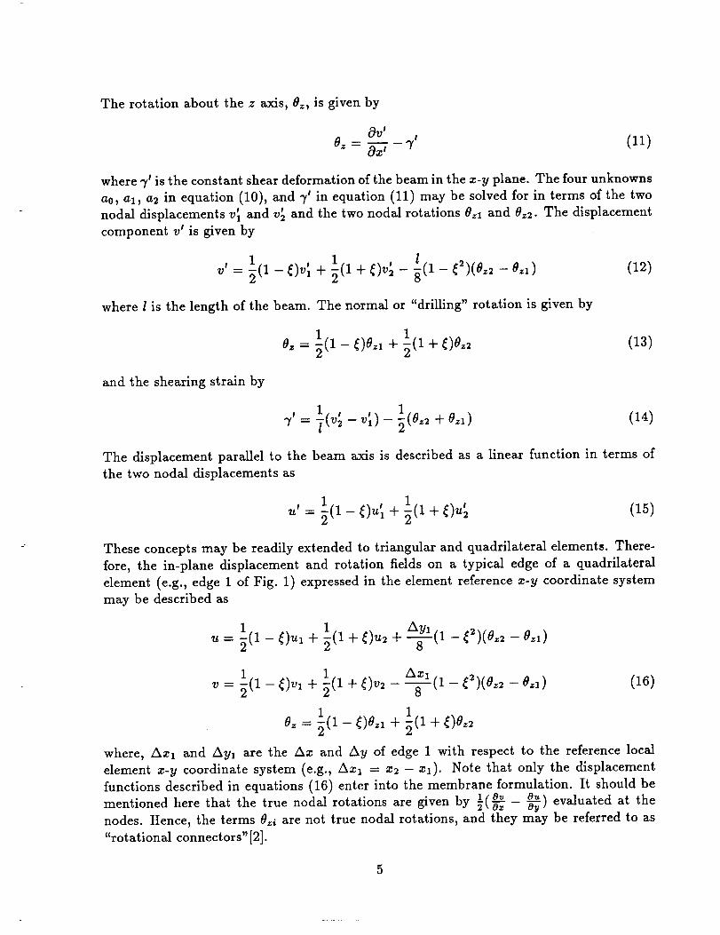
The rotation about the z axis, 0z, is given by
- 7' (11)Oz Oz'
where 7 _is the constant shear deformation of the beam in the z-V plane. The four unknowns
a0, al, a2 in equation (10), and 3" in equation (11) may be solved for in terms of the two
nodal displacements vl and v_ and the two nodal rotations 0zl and 0_2. The displacement
component v' is given by
(12)
where l is the length of the beam. The normal or "drilling" rotation is given by
Oz = 1(1 - _)0_1 + 1(1 + _)0_2 (13)
and the shearing strain by
7' 1 , , l (Oz2 + 0_1)= - - (14)
The displacement parallel to the beam axis is described as a linear function in terms of
the two nodal displacements as
(15)
These concepts may be readily extended to triangular and quadrilateral dements. There-
fore, the in-plane displacement and rotation fields on a typical edge of a quadrilateral
dement (e.g., edge 1 of Fig. 1) expressed in the element reference z-y coordinate system
may be described as
u --= l (1-- _)ul T1(1+ _)u2 q- _---_l (1--_2)(Oz2 -- Oz1)
2 (1 - - )
1 AZl
v= (l-t_)vl + (l+t_)v2-(16)
0z = 2(1 - f)0.1 + 1(1 + f)0z2
where, Am1 and Ayl are the Am and Ay of edge 1 with respect to the reference local
dement x-y coordinate system (e.g., Axl = z2 --zl). Note that only the displacement
functions described in equations (16) enter into the membrane formulation. It should be
mentioned here that the true nodal rotations are given by ½(°'_ o,,o_ _) evaluated at the
nodes. Hence, the terms O_i are not true nodal rotations, and they may be referred to as
"rotational connectors"[2].

In references [2-5], the above displacement functions were used for construction of mem-
brane elements. However, this same procedure may also be used for development of a bend-
ing element. Again, quadratic functions are used to describe the out-of-plane displacement
component w and linear functions are used to described the out-of-plane rotations #z and
0_ along each edge of the element. The final result for the out-of-plane displacement and
rotation fields on edge 1 of Figure 1 is
w = l (1- _)wl +1(l + _)w2 - --Ayl
(1- _)(e_2 - e_l) + -=-_(1 - _2)(e_ - 0_1)8 O
1 1e_ = _(1- _)o_ + (1+ _)e_
1 (1 + _)0_2e_= (1- _)e_ +
(17)
Equations (16) and (17) indicate that both the membrane part and the bending part of
the element are formulated in the same manner. All three displacement components are
quadratic functions, while all three rotations are linear functions. This conformity in the
order of the approximating polynomials for all displacement components and all rotation
components is very desirable in the analysis of shell problems.
The basic concept of the element is similar to that of Cook's proposed 4-node membrane
element[3]. However, this concept is extended in this paper to the bending problem in order
to construct a 4-node fiat shell element. Internally the element is an 8-node isoparametric
quadrilateral element. Externally, the midside degrees of freedom of the 8-node element
are approximated by the above displacement and rotation functions, so that the midside
degrees of freedom are eliminated at the expense of adding drilling degrees of freedom to
the 4-node element. For example, on edge 1 of Figure 1, the midside degrees of freedom
are given by evaluating the functions in equations (16) and (17) at _ = 0. This gives
1 __
1 Azl (ez_- e_l)v5 = _(vl + v2) 8
1 _ Awl [nw5 -- _(wl + w;)- (e_2 - 0_1) + --_,_2 - e_l) (lS)
1 e
1
The description for other midside nodes is readily obtained. It is not necessary to evaluate
the function Oz in equations (16) at _ -- 0 since the normal rotation 8z does not enter
into the membrane formulation. It is observed that the extra nodal degrees of freedom are
t

associated with the membrane part of the element only. The bending part of the problem
does not add any extra degrees of freedom to the element.
Equations (16), when extended to all four sides of the element, indicate that the membrane
part of the element has 12 degrees of freedom. Two of these are the in-plane translational
rigid body motions and one is the in-plane rotational rigid body motion. Of the nine
remaining degrees of freedom, three represent the constant strain states, five represent
higher-order strain states, and the final degree of freedom represents a special type of zero-
energy "spurious" mode. This zero-energy mode is associated with a state of zero nodal
displacements and equal nodal rotations. This state renders the u and v displacement
components in equations (16) zero on all four sides of the quadrilateral, while all four
corner nodes of the quadrilateral are rotated about its normal by equal amounts Oz. This
mode is shown in Figure 2 using cubic interpolation for displacements and may be called
a "zero displacement" mode[2]. It occurs because the quadratic displacement functions
are based on the differences of the nodal rotations and not the nodal rotations themselves.
One of these differences is dependent on the other three. Therefore, the membrane part
of the element has, in fact, only 11 independent displacement modes but is expressed in
terms of 12 degrees of freedom. Hence: one of the normal rotational degrees of freedom
is extraneous and must be eliminated. This zero-energy mode is of a special type and is
different from other spurious mechanisms such as the hour-glass mode. In reference [4], this
zero-energy mode is removed by artificially adding a small energy penalty to the stiffness
matrix to make the stiffness matrix non-singular. Although, this could be accomplished
with little effort, prescribing the value of normal rotation for at least one node in the entire
finite element model of the structure will eliminate this extraneous degree of freedom.
Equations (17) indicate that the bending part of the element also has 12 degrees of freedom.
One of these is the out-of-plane translational rigid body motion and two of these are the
out-of-plane rotational rigid body motions. Of the nine remaining degrees of freedom,
three represent the constant curvature states, two represent the constant transverse shear
strain states, and the other four represent higher-order strain states. No zero-energy modes
are associated with the bending part of the element. Note that although the displacement
function w described in equations (17) is also in terms of the differences of the nodal
rotations and not the rotations themselves, each one of the nodal rotations are accounted
for by the functions 0z and 0_ in equations (17). This is not the case for the membrane
part because the rotation function Oz in equations (16) does not enter into the membrane
formulation, while both rotation functions 0_ and 0y in equations (17) enter into the
bending formulation.
Stress Field Description
The stress field should be selected in such a manner that no spurious zero-energy mode
is produced. A spurious zero-energy mode is produced when the product of a selected
stress term and the strains that are derived from the displacement functions produces
zero strain energy under a particular, but not trivial, deformational displacement field. In
order to avoid spurious zero-energy modes, each independent stress term must suppress
one independent deformation mode. The problem of spurious zero-energy modes generally
occurs for regular geometries such as rectangular planar elements and brick solid elements

and it disappears for irregular geometries[14].
As discussed previously, the membrane part of the element has 12 degrees of freedom--
three of which are due to the in-plane rigid body motions. Therefore, a stress field with
a minimum of 9 independent parameters is needed to describe the membrane stress (re-
sultant) field. The following stress (resultant) field is first considered for the membrane
part
N_ = Zl + _,_ + _6_ + _8_
1 2 1_2N_, = _3 - _8_ - _,_ - 5_8'I -
(19)
This stress (resultant) field is obtained by integrating, through the thickness, the com-
ponents of the contravariant stress tensor expressed in the natural coordinates. These
components must be transformed to the physical stress components in the element refer-
ence coordinates by contravariant tensor transformation laws. However, the components
of the transformation are evaluated at the origin of the natural coordinates in order to
retain the constant terms in the stress field description[l 1-13]. When the stress (resultant)
field in equations (19) is specialized to the rectangular coordinate system, the stress resul-
tants of the stress field assumed by Robinson[15,16] for his 8-node and 4-node membrane
elements are obtained. In the above stress (resultant) field, the first five terms represent
the stress field that was used in Plan's 4-node assumed-stress hybrid membrane element
which had no rotational degrees of freedom[ll-13]. The remaining terms are present to
suppress the rotational degrees of freedom present in this formulation. However, experi-
mentations with a single rectangular element revealed that the stress (resultant) field in
equations (19) produces one spurious zero-energy mode. It should be mentioned here that
Robinson's suggested stress field worked for his formulation which was based on a cubic
displacement field. Therefore, it is proposed herein to use the following 9-term stress field
for the membrane part
Ne = _1 + _4,7+ f_6_+ f_8_2
N_,, = _ - _,7 - _
(20)
This stress field produces no spurious zero-energy mode for the assumed displacement field
described in equations (16) for the membrane part. When the elements are rectangular in
shape this selection of stress field satisfies the equations of equilibrium a priori. In reference
[5], a different 9-term stress field was selected which assumes linear variation for all stress
components which satisfies equilibrium in a variational sense for all element geometries
including rectangular-shaped elements.
The bending part of the element has 12 degrees of freedom--three of which are due to the
out-of-plane rigid body motions. Therefore, a stress field with a minimum of 9 independent
parameters is needed to describe the stress field. The following stress (resultant) field is

chosenfor the bending part
g, -- A + A_ + A,7 + A_,7I- 2 1- 2
Me, = A + _io_ + _1_,7+ _i_ + _,7
(21)
The transverse shear forces are taken to be derived from the moments such that the
equilibrium equations are satisfied for rectangular elements
Q_ = M_,_+ M07,. (22)Q. = Me.,e + M.,.
which gives
Q_ = (_6 +/3zl) + (/_s +/3z3)_7 (23)
¢, = (A + _10)+ (A + _1_)_
Again, this stress (resultant) field is obtained by integrating, through the thickness, the
components of the contravariant stress tensor expressed in the natural coordinates and
must be transformed to the physical components in the element reference coordinates bycontravariant tensor transformation laws. As for the membrane part, the components of the
transformation are evaluated at the origin of the natural coordinates in order to retain the
constant terms in the stress field description. This stress field selection for the bending part
satisfies the equations of equilibrium for rectangular-shaped elements a priori. When the
above bending stress resultant field is specialized to the rectangular coordinate system, one
obtains the resultants of the stress field that was derived in references [6-8]. The derivation
of the stress field in references [6-8] consists of expressing the stress components as power
series in the plate thickness, substituting these stresses into the continuum equations of
elasticity, and equating the coefficients of like powers of the plate thickness. As discussed
earlier, this 13 parameter selection of stresses for bending is less sensitive to geometric
distortion than a 9 parameter selection obtained from a degenerate solid model[9]. This
selection of stresses produces no spurious zero-energy modes.
In this paper, the Reissner-Mindlin Plate theory is used for the bending part. The bending
part is of class C ° and takes into account the effects of transverse shear deformations by
assuming constant transverse shear strains through the thickness of the plate. This means
that the transverse shear stresses are also constant through the thickness of the plate.
However, generally the transverse shear stresses are zero on the plate surfaces. Therefore,
a parabolic variation of transverse shear stresses and strains through the plate thickness
is more reasonable. To account for this discrepancy, a static correction factor of 5/6 is
included in the transverse shear strain energy, see Reissner[17].
Other Element Matrices
Other element matrices needed to complete the element formulation may be derived in a
similar fashion. The element force vector F in equation (9) may be derived in a manner
9
consistentwith the stiffnessmatrix. The surfacetraction and pressureloads areassumedto
vary bilinearly over the element surface and the force vector F of equation (9) is calculatedfor the "internal" 8-node element. This force vector is then condensed to that of the 4-node
dement using the approximations for the midside degrees of freedom described earlier. For
line load calculations, on the other hand, it is not necessary to use the "internal" 8-node
element. The force vector F corresponding to line loads may be calculated directly based
on the 4-node element by assuming linear variation of line loads on the edges of the element
and using the displacement and rotation shape functions derived earlier.
The mass and geometric stiffness matrices for the present element may also be derivedfrom the ':internal" 8-node element in the same manner as for the stiffness matrix.
Numerical Results
Assessment of the 4-node quadrilateral shell element developed in this paper is presented in
this section. The element has been implemented in the CSM Testbed Software System[18]
using the generic element processor template[19]. Selected test problems include the patch
test, the straight cantilever beam, the curved cantilever beam, the twisted cantilever beam,
the Cook's tapered and swept panel, the thick-walled cylinder, and the Scordelis-Lo roof
problem. The assumed-stress hybrid/mixed flat shell quadrilateral element derived in this
paper will be referred to as AQR8 (Assumed-stress Quadrilateral Reduced from an 8-node
element) in the following discussion for convenience. The results for the present element
are compared with the results using the QUADg element of the MSC/NASTRAN from
reference [20], the Q4S element of reference [4], the AQ element of reference [5], and the
ES1/EX47, ES5/Egl0, and ES4/EX43 elements of the NASA Langley CSM Testbed. A
brief description of these elements is given in the appendix. The dimensions and properties
for the test problems are chosen in consistent units.
Patch Test
As the first test of the accuracy of the element, the patch test problem suggested in
reference [20] is solved. This patch test is shown in Figure 3. Elements of arbitrary shapes
are patched together to form a rectangular exterior boundary which makes it easy to apply
boundary conditions corresponding to constant membrane strains and constant bending
curvatures. The applied displacement boundary conditions and the theoretical solutions
are also shown in Figure 3. The ability of the element to reproduce constant states of
strains is an essential requirement for achieving convergence to the correct solution as the
finite element mesh is refined. This requirement is observed by considering an individual
element within a mesh with a complicated stress field. As the mesh is refined, the stresses
within the elements tend towards a uniform value. Therefore, the elements that cannot
produce a state of constant strains should not be trusted to converge to the correct solution
as the mesh is refined[l]. The present element (AQR8) passes both the membrane and the
bending patch tests with no error. The recovered strains and stresses are both exact.
Straight Cantilever Beam
As a second test, the straight cantilever beam problem suggested in reference [20] is solved
for the three discretizations (six elements) shown in Figure 4. The constant and linearly
10

varying strains and curvatures are evoked by applying loads at the free end of the beam
to test the ability of the element to recover these states of deformations. The theoretical
results for extension, in-plane shear, out-of-plane shear, and in-plane moment are simply
calculated from the elementary beam theory including shear deformations. The theoretical
result for the twist is .03406, according to Timoshenko and Goodier's Theory of Elastic-
ity[21]. Reference [20] quotes the answer to be .03208. Analysis with three successively
refined meshes converged to .03385 which is much closer to the theory of elasticity solu-
tion than to that of reference [20]. Therefore, the solution from the theory of elasticity
is taken herein for normalization purposes. The normalized results are shown in Table 1.
The results show that all elements perform well for the rectangular mesh. However, for the
trapezoidal and parallelogram meshes which contain considerable distortions, only the Q4S
element and the present element (AQR8) are adequate. For the present element, while the
error for all meshes and loads is less than 3.5%, the parallelogram mesh with a twist end
load exhibits an error of 15.9% which shows the sensitivity of the selected bending stress
field to mesh distortion.
Curved Cantilever Beam
Next, the curved cantilever beam problem shown in Figure 5 is solved. The beam is
formed by a 90 ° circular arc. In-plane and out-of-plane loads are applied at the free end
to produce in-plane and out-of-plane deformations, respectively. The theoretical solutions
are taken to be those quoted in reference [20]. The normalized results from the present
element (AQR8) are tabulated in Table 2. Also shown in Table 2 are the results from
other elements for comparison. In this problem the mesh is distorted only slightly and
the results for all elements are good. However, it is seen that the AQR8 element performs
better than the other elements in the table, particularly for the in-plane shear loading.
Twisted Cantilever Beam
The twisted cantilever beam problem is shown in Figure 6. The beam is twisted 90 ° over
its length. There are 12 elements along the length of the beam. Therefore, each element
has a 7.50 warp. The beam is subjected to in-plane or out-of-plane unit loads at its free
end. Both the membrane and the bending contributions are significant for either type
of load. The theoretical solutions are taken to be those quoted in reference [20]. The
normalized results from the present element (AQR8) are tabulated in Table 3. Also shown
in Table 3 are the results from other elements for comparison. In this problem the mesh
is comprised of rectangular shaped elements and there is no in-plane mesh distortion.
Therefore, this problem tests the sensitivity of the elements due to warp distortion. The
results show that, although the AQR8 element exhibits good performance, the QUAD4
element performs even better for this problem.
Cook's Tapered and Swept Panel
The tapered and swept panel with one edge clamped and the other edge loaded by a
distributed shear force is analyzed next (see Fig. 7). This problem was used by Cook
and many other researchers to test the sensitivities of finite elements due to geometric
distortions. The panel was analyzed by a coarse 2×2 mesh and a finer 4x4 mesh. The
reference solution for the vertical displacement at point C is taken to be 23.90 quoted in
reference [5] as the best known answer. The normalized results for the present element
11

(AQR8) along with the results for other elements are shown in Table 4. The mesh for this
problem is distorted only slightly and all the elements produce reasonable results. The
AQR8 element, however, yields results that are closest to the best known answers.
Thick-Walled Cylinder
The thick-walled cylinder problem is shown in Figure 8. This problem was suggested by
reference [20] to test the performance of finite elements for nearly incompressible materi-
als. Plane strain conditions and radial symmetry are assumed so that the only non-zero
displacement component is in the radial direction. The theoretical solution for this prob-
lem is given in any standard text bOO k on elasticity (e.g.i see reference [21]) and is shown
ill Figure 8. The normalized results for the present element (AQR8) along with the re-
sults for other elements are shown in Table 5. The mesh in this problem is distorted
only slightly and the main purpose is to test the behavior of the elements for nearly in-compressible materials. It is observed that, while the pe-rf0rmance of the hybrid elements
(i.e., the ES4/EX43 and the AQR8 element) does not deteriorate as the Poisson ratio
approaches 0.5, the other elements fail to retain their performance. This insensitivity to
nearly incompressible materials is a trait of assumed-stress hybrid elements.
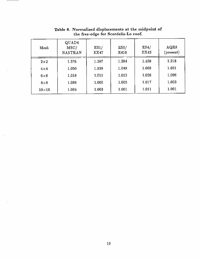
Scordelis-Lo Roof
Finally, the Scordelis-Lo roof shown in Figure 9 is analyzed. This structure is a singly
curved shell problem in which both the membrane and the bending contributions to the
deformation are significant. The result reported in most references is the vertical dis-
placement at the midpoint of the free-edge. The theoretical value for this displacement is
quoted in reference [22] to be 0.3086, but the reference value quoted in reference [20] is0.3024 for normalization of results. The latter value is also used herein for normalization
purposes. Because of symmetry, only one quadrant of the problem is modeled. The mesh
on one quadrant is chosen to be NxN for N=2,4,6,8,10 (N=number of elements along each
edge) to show the convergence of the solutions for the AQR8 element. The results of the
normalized displacement at the midside of the free-edge are shown in Table 6. The results
for other elements are also shown in Table 6 for comparison. The mesh for this problem
is comprised of rectangular shaped elements and all the elements in the table seem to
perform well.
Conclusions
A 4-node quadrilateral shell element with 24 degrees of freedom has been developed whichalleviates most of the deficiencies associated with 4-node shell elements. The element is
based on the assumed-stress hybrid/mixed formulation using the Hellinger-Reissner princi-
ple. The membrane part of this element has 12 degrees of freedom and includes the drilling
(in-plane rotational) degrees of freedom at the nodes. The bending part of this element
also has 12 degrees of freedom. The bending part is of class (7 o and takes into account the
transverse shear deformations. Both in-plane and out-of-plane displacements are assumed
to have quadratic variations along the edges of the element, while both in-plane and out-
of-plane rotations are assumed to vary linearly. A 9-parameter stress field is assumed for
the membrane part and a 13-parameter stress field is assumed for the bending part. The
element formulation is derived from an 8-node isoparametric element by eliminating the
12

midside degrees of freedom in favor of rotational degrees of freedom at corner nodes. Al-
though the concepts of the present element are simple, the derivation and implementation
of the element is somewhat awkward and indirect. Nearly all element matrices are derived
based on an "internal" 8-node element.
Results from the numerical studies demonstrate that this element is accurate, passes both
the membrane and the bending patch tests, does not "lock", has no spurious modes,
and is nearly insensitive to mesh distortion. The present element also has the desirable
property of being invariant with respect to node numbering. The results indicate that
whereas the present element offers little advantage for problems with nearly rectangular
meshes, it produces more accurate results when dealing with distorted meshes, than the
other elements for the majority of test cases in this paper. This is important in general
modeling of shell problems and adaptive refinement. The results also indicate that the
present element produces more accurate results than the other elements in this paper
when dealing with nearly incompressible materials, which is a consequence of assumed-
stress hybrid element formulation.
Results obtained to date warrant further research in making the element formulation more
direct and extending the capabilities of the element to include stability analysis, dynamic
analysis, and non-linear analysis.
References
1. Irons, ]3. M.; and Ahmad, S.: Techniques of Finite Elements. John Wiley and Sons,
New York, 1980.
2. Allman, D. J.: A Compatible Triangular Element Including Vertex Rotations for Plane
Elasticity Analysis. Computers and Structures, Vol. 19, No. 1-2, 1984, pp. 1-8.
3. Cook, R. D.: On the Allman Triangle and a Related Quadrilateral Element. Com-
puters and Structures, Vol. 22, No. 6, 1986, pp. 1065-1067.
4. MacNeal, R. H.; and Harder R. L.: A Refined Four-Noded Membrane Element with
Rotational Degrees of Freedom. Computers and Structures, Vol. 28, No. 1, 1988, pp.
75-84.
5. Yunus, S. H.; Saigal S.; and Cook, R. D.: On Improved Hybrid Finite Elements
with Rotational Degrees of Freedom. International Journal for Numerical Methods in
Engineering, Vol. 28, 1989, pp. 785-800.
6. Friedrichs, K. O.; and Dressier, R. F.: A Boundary-Layer Theory for Elastic Plates.
Communications on Pure and Applied Mathematics, Vol. 14, 1961, pp. 1-33.
7. Reiss, E. L.; and Locke, S.: On the Theory of Plane Stress. Quarterly of Applied
Mathematics, Vol. 19, No. 3, 1961, pp. 195-203.
8. Laws, N.: A Boundary-Layer Theory for Plates with Initial Stress. Cambridge Philo-
sophical Society Proceedings, Vol. 62, 1966, pp. 313-327.
13

9. Kang, D.: Hybrid StressFinite Element Method. Ph.D. Dissertation, MassachusettsInstitute of Technology,Cambridge, MA, May 1986.
10. Pian, T. H. H.: Derivation of Element StiffnessMatrices by AssumedStressDistribu-tions. AIAA Journal, Vol. 2, 1964,pp. 1333-1336.
11. Plan, T. H. H.: Evolution of AssumedStressHybrid Finite Element. Accuracy,Relia-bility and Training in FEM Technology,Proceedingsof the Fourth World CongressandExhibition on Finite Element Methods, The CongressCenter,Interlaken, Switzerland,Edited by John Robinson, September17-21,1984,pp. 602-619.
12. Plan, T. H. H.; and Sumihara K.: Rational Approach for Assumed Stress FiniteElements. International Journal for Numerical Methods in Engineering, Vol. 20,1984,pp. 1685-1695.
13. Pian, T. H. H.: Finite Elements Basedon Consistently Assumed Stressesand Dis-placement. Finite Elementsin Analysis and Design, Vol. 1, 1985,pp. 131-140.
14. Plan, T. H. H.; and Chen, D.: On the Suppressionof Zero Energy DeformationModes. International Journal for Numerical Methods in Engineering,Vol. 19, 1983,pp. 1741-1752.
15. Robinson, J.: An Accurate and Economical Eight-Node StressMembrane Element.International Journal for Numerical Methods in Engineering, Vol. 15, 1980,pp. 779-789.
16. Robinson, J.: Four-Node Quadrilateral Stress Membrane Element with RotationalStiffness. International Journal for Numerical Methods in Engineering,Vol. 16, 1980,pp. 1567-1569.
17. Reissner,E.: On Bendingof Elastic Plates. Quarterly of Applied Mathematics, Vol. 5,1947,pp. 55-68.
18. Knight, N. F., Jr.; Gillian, R. E.; McCleary, S. L.; Lotts, C. G.; Poole, E. L.; Over-
man, A. L.; and Macy, S. C.: CSM Testbed Development and Large-Scale Structural
Applications. NASA TM-4072, April 1989.
19. Stanley, G. M.; and Nour-Omid, S.: The Computational Structural Mechanics Testbed
Generic Structural-Element Processor Manual. NASA CR-181728, March 1990.
20. MacNeal, R. H.; and Harder, R. L.: A Proposed Standard Set of Problems to Test
Finite Element Accuracy. Finite Elements in Analysis and Design, Vol. 1, No. 1,
1985, pp. 3-20.
21. Timoshenko, S. P.; and Goodier, J. N.: Theory of Elasticity, McGraw-Hill, Third
Edition, 1970.
22. Scordelis, A. C.; and Lo, K. S.: Computer Analysis of Cylindrical Shells. Journal of
the American Concrete Institute, Vol. 61, 1969, pp. 539-561.
23. MacNeal, R. H.: A Simple Quadrilateral Shell Element. Computers and Structures,
Vol. 8, 1978, pp. 175-183.
14

24. Park, K. C.; and Stanley, G. M.: A Curved C o shell Element Based on Assumed
Natural-Coordinate Strains. Journal of Applied Mechanics, Vol. 108, 1986, pp. 278-
290.
25. Stanley, G. M.: Continuum-Based Shell Elements. Ph.D. Dissertation, Stanford Uni-
versity, Stanford, CA, August 1985.
26. Rankin, C. C.; Stehlin, P.; and Brogan, F. A.: Enhancements to the STAGS Computer
Code. NASA CR-4000, 1986.
27. Aminpour, M. A.: Assessment of SPAR Elements and Formulation of Some Basic 2-D
and 3-D Elements for Use with Testbed Generic Element Processor. Proceedings of
NASA Workshop on Computational Structural Mechanics - 1987, NASA CP-10012-
Part 2, Nancy P. Sykes, (Editor), 1989, pp. 653-682.
15

Appendix
The following is a brief description of the elements used in Tables 1-6 for comparison with
the element developed in this paper.
The QUAD4 MSC/NASTRAN element is a 4-node isoparametric shell element with selec-
tive reduced-order integration. The transverse shear uses a string-net approximation and
augmented shear flexibility[23]. This element was developed by MacNeal and is available
in the MSC/NASTRAN finite element code.
The Q4S element is a 4-node shell element in which the membrane part is formulated
internally as an 8-node isoparametric element with selective reduced-order integration and
later reduced to a 4-node element by eliminating the midside degrees of freedom in favor
of rotational degrees of freedom at the corner nodes. This element was developed by
MacNEAL[4]. The bending part of the Q4S is the same as that of the QUAD4[4].
The AQ element is a 4-node assumed-stress hybrid/mixed membrane element which is
formulated internally as an 8-node isoparametric membrane element and later reduced to
a 4-node membrane element by eliminating the midside degrees of freedom in favor of
rotational degrees of freedom at the corner nodes. This element was developed by Yunus
et al.[5]. The only result reported in reference [5] for the cantilever beam problem in
Table 1 using the AQ element is for the mesh with trapezoidal-shaped elements with a
unit in-plane end moment. This result is reported to be .85. The difference in the results
between the AQ membrane element and the membrane part of AQR8 is in the selectionof the assumed-stress functions.
The ES1/EX47 element is a 4-node C o isoparametric assumed natural-coordinate strain
(ANS) shell element developed by Park and Stanley[24-25] and implemented in the CSM
Testbed Software System[18] by Stanley using the generic element processor template[19].
This element is not invariant and does not pass the patch test. This element does not
include the drilling degrees of freedom in the formulation.
The ES5/E410 element is a 4-node C 1 shell element which was originally implemented in
the STAGS finite element code and later in the CSM Testbed by Rankin[26]. This element
includes the rotational degrees of freedom in its formulation and uses cubic interpolation
for all displacement fields. This element is not invariant and does not pass the patch test.
The ES4/EX43 element is a simple 4-node C o isoparametric assumed-stress hybrid/mixed
shell element implemented in the CSM Testbed by this author[27]. This element passes
the patch test and is invariant with respect to node numbering. This element does not
include the drilling degrees of freedom in its formulation and uses linear interpolation for
all displacement and rotation fields.
16

Table 1. Normalized tip displacements in direction of
loads for straight cantilever beam.
Tip Loading
Direction
QUAD4
MSC/NASTRAN
ES1/ ESh/EX47t E410t
ES4/
EX43
AQR8
(present)
(a) rectangular shaped elements
Extension
In-plane Shear
Out-of-Plane Shear
Twist
End Moment
.995
.904*
.986
.941"*
.995
.904
.980
.856
.910
.994
.915
.986
.680
.914m
(b) trapezoidal shaped elements
.996
.993
.981
1.023
1.000
.998
.993
.981
1.011
1.000
Extension
In-plane Shear
Out-of-Plane Shear
Twist
End Moment
.996
.071"
.968
.951"*
(c) parallelogram
.761
.305
.763
.843
.505
shaped
.991
.813
#
#
.822
.999
.052
.075
1.034
.102
.998
:986
.965
1.029
.996
elements
Extension
In-plane Shear
Out-of-Plane Shear
Twist
End Moment
.996
.080*
.977
.945**
.966
.324
.939
.798
.315
.989
.794
.991
.677
.806
.999
.632
.634
1.166
.781
.998
.977
.980
1.159
.989
t These elements are not invariant and do not pass the patch test.
* The results from MacNeal's Q4S element for in-plane shear load are reported in ref-erence [4] to be .993, .988, and .986 for the meshes in (a), (b), and (c) respectively.
** These results for twist were normalized with .03028 in reference [20]. Herein, allthe other results for twist are normalized using .03046 according to Timoshenko andGoodier's Theory of Elasticity[21].
# The element produces a singular stiffness matrix for this mesh.
17

Table 2. Normalized tip displacements in direction of
loads for curved cantilever beam.
Tip Loading
Direction
In-plane Shear
Out-of-Plane Shear
QUAD4
MSC/NASTRAN
.833
.951
ES1/
EX47
.929
.935
ES5/E410
.938
.887
ES4/
EX43
.888
.925
AQR8
(present)
.997
.956.r
Table 3. Normalized tip displacements in direction of
loads for twisted cantilever beam.
Tip Loading
Direction
In-plane Shear
Out-of-Plane Shear
QUAD4
MSC/
NASTRAN
.993
.985
ES1/
EX47
1.357
1.293
ES5/E410
1.054
1.173
ES4/
EX43
1.361
1.359
AQR8
(present)
.991
1.093
Table 4. Normalized vertical deflection at point C
for tapered and swept panel.
Mesh
2x2
4x4
AQ
.914
.973
ES1/
EX47
.880
.953
ES5/E410
.873
.953
ES4/
EX43
.882
.962
AQR8
(present)
.930
.979
Poisson's
Ratio
0.49
0.499
0.4999
Table 5. Normalized radial displacements at inner
boundary for thlck-wailed cylinder.
QUAD4
MSC/NASTRAN
.846
.359
.053
ES1/
EX47
.831
.352
.052
ES5/
E410
.848
.360
.053
ES4/
EX43
.990
.990
.990
AQR8
(present)
.989
.988
.988
18
Mesh
2x2
4x4
6x6
8×8
10x10
Table 6. Normalized displacements at the midpoint of
the free-edge for Scordelis-Lo roof.
QUAD4
MSC/NASTRAN
1.376
1.050
1.018
1.008
1.004
ESl/EX47
1.387
1.039
1.011
1.005
1.003
ES5/E410
1.384
1.049
1.015
1.005
1.001
ES4/
EX43
1.459
1.068
1.028
1.017
1.011
AQR8
(present)
1.218
1.021
1.006
1.003
1.001
19

4
7
_ 62 _v X
Figure 1. Element coordinate system definition.
OZ 4 --0 z
Oz3 =0 z
ezl =ez %2 =ez
Figure 2. The "zero displacement" mode.
2O

a
__.__ ×
Location of nodes:
.node x y
1 .04 .02
2 .18 .03
3 .16 .08
4 .08 .08
Applied displacements:
(a) Membrane patch test
Boundary conditions:
Theoretical solution:
(b) Bending patch test
Boundary conditions:
u = 10-3(. + u/e)v = 10-3(./2 +y)
e** = %y = _zy ----10-3
o'._ = o_ = 1333., o'_ = 400.
w = -lO-3(x 2 + zy + y2)/2
e_ =-lo-_(_/2 +_)0y = -lO-Z(x + y/2)
Theoretical solution:
Bending moments per unit length:
M_ = My = 1.111×10 -v, M_ = 3.333×10 -s
Surface stresses:
_r_, = a_y = -t-0.667, a_ = -4-0.200
Figure 3. The patch test problem, a=0.24, b=0.12, t=0.001, E=10 s, v=0.25.
(Consistent units are used for various properties.)
21

1 I I Ia) rectangular shape elements
45',,, ,/ \
b) trapezoidal shape elements
45
45
/ ,/ /c) parallelogram shape elements
Theoretical solutions:
Tip load direction Displacement in direction of load
Extension .3 x 10 -4
In-plane shear .1081
Out-of-plane shear .4321
Twist .03406
In-plane moment .009
Figure 4. Straight cantilever beam problem. Length=6., height=0.2, depth=0.1, E=107,
u=0.3, mesh=6×l. Loading: unit forces at the free end.
22

9O
Theoretical solutions:
Tip load direction Displacement in direction of load
In-plane shear .08734Out-of-plane shear .5022
Figure 5. The curved cantilever beam problem. Inner radius=4.12, outer radius=4.32,depth=0.1, E=107, v=0.25, mesh=6xl. Loading: unit forcesat the free end.(Consistent units areusedfor various properties.)
23

Theoretical solutions:
Tip load direction Displacement in direction of load
In-plane shear .005424
Out-of-plane shear .001754
Figure 6. The twisted cantilever beam problem. Length=12., width=l.1, depth=0.32,
twist=90 ° (root to tip), E=29. x10 _, v=0.22, mesh=12x2. Loading: unitforces at the free end.
(Consistent units are used for various properties.)
24

48 _--_,_ (48,60)
_ .._/(48,44) l
(0,22) "_ 4i
(o,o)(a)
Figure 7.
_-- 48 -----_|,
10 16
44
(b)The tapered and swept panel problem. Thickness=l, E=I., r,=l/3,
mesh=N×N. Loading: unit in-plane shear force distributed on the free edge.
Reference solution: Vertical displacement at C=23.90 from reference [10].(a) 2x2 mesh, (b) 4x4 mesh.
(Consistent units are used for various properties.)
25

Theoretical solutions:
(1 + v)pR_ [R_/," + (1 - 2v)r]u(r) = E(R_ - R_)
where p=pressure on the inner surface, R1 =inner radius, R2=outer radius.
Poisson's ratio, v Radial displacement at r = R1
.49 5.0399x 10 -3
.499 5.0602×10 -3
.4999 5.0623 x 10⁻³
Figure 8. The thick-walled cylinder problem. Inner radius=3., outer radius=9.,
thickness=l., E=1000., plane strain condition, mesh=5xl as shown.
Loading: unit pressure on inner boundary.
(Consistent units are used for various properties.)
26

Figure 9.
Z
Yx
,\\_' R\
The Scordelis-Lo roof problem. Length=50., radius=25, thickness=0.25,
E=4.32×10s_ u=0.3_ mesh=NxN. Loading: 90. per unit area in vertical direc-
tion, i.e., gravity load; u_=uz=O on curved edges. Reference solution: vertical
displacement at midpoint of free-edge=0.3024 from reference [23].
(Consistent units are used for various properties.)
27

n_L
i-
L

Nat,onal Aeronau_lcs and
Space Ad,'n_n_s[ra_oo
1. Report No.
NASA CR-4279
4. Title and Subtitle
Report Documentation Page
2. Government Accession No.
3. Recipient's Catalog No.
5. Report Date
A 4-Node Assumed-Stress Hybrid Shell Element With Rotational
Degrees of Freedom
7. Author(s)
Mohammad A. Aminpour
9. Performing Organization Name and Address
Analytical Services and Materials, Inc.
Hampton, VA 23666
12. Sponsoring Agency Name and Address
National Aeronautics and Space Administration
Langley Research CenterHampton, VA 23665-5225
April 1990
6. Performing Organi_ation Code
8. Performing Organization Report No.
10. Work Unit No.
505-63-01-10
11. Contract or Grant No.
NASI-18599
13. Type of Report and Period Covered
Contractor Report
14. Sponsoring Agency Code
15. Supplementary Notes
Langley Technical Monitor: W. Jefferson Stroud16. Abstract
An assumed-stress hybrid/mixed 4-node quadrilateral shell element is introduced that alleviates most ofthe deficiencies associated with such dements. The formulation of the element is based on the assumed-
stress hybrid/mixed method using the Hellinger-Reissner variational principle. The membrane part of
the element has 12 degrees of freedom including rotational or "drilling" degrees of freedom at the nodes.
The bending part of the element also has 12 degrees of freedom. The bending part of the element uses the
Reissner-Mindlin plate theory which takes into account the transverse shear contributions. The dement
formulation is derived from an 8-node isoparametrie element. This process is accomplished by assuming
quadratic variations for both in-plane and out-of-plane displacement fields and linear variations for both
in-plane and out-of-plane rotation fields along the edges of the element. In addition, the degrees of freedom
at midside nodes are approximated in terms of the degrees of freedom at corner nodes. During this process
the rotational degrees of freedom at the corner nodes enter into the formulation of the element. The stress
field is expressed in the element natural-coordinate system such that the dement remains invariant with
respect to node numbering. The membrane part of the dement is based on a 9-parameter stress field,while the bending part of the element is based on a 13-parameter stress field. The element passes the
patch test, is nearly insensitive to mesh distortion, does not "lock", possesses the desirable invariance
properties, has no spurious modes, and for the majority of test eases used in this paper produces more
accurate results than the other elements employed herein for comparison.
17. Key Words (Suggested by Authors(s))assumed-stress, hybrid, mixed, element, finite element,
quadrilateral, shell, drilling, variational
19. Security Classif.(of thls report)
Unclassified
18. Distribution Statement
Unclassified--Unlimited
NASA FORM 1826 OCT ss
20. Security Classif.(of this page)Unclassified
Subject Category 39
21. No. of Pages[22. Price28 ] A03
For sale by the National Technical Inforn, mtion Service, Springfield, Virginia 22161-2171
' NASA.Langley, 19_


