SDMMARY OFNASALANDINGGEARRESEARCH · PDF fileSDMMARY OFNASALANDINGGEARRESEARCH ... on slippery...
32
SDMMARY OFNASALANDINGGEARRESEARCH Bruce D. Fisher. Rohert K. Sleeper, and Sandy M. Stubbs NASA Langley Research Center SUMMARY The landing gear research being conducted at NASA Langley Research Center is summarized in this report, and research relative to tire tread, powered-wheel taxiing, air cushion landing systems, and crosswind landing gear is discussed in some detail. INTRODUCTION The purpose of this paperis to present a brief summary of the airplane landing-gear research underway at NASA. The technology areas include: Ground-handling simulator Tire/surface friction Antiskid braking systems characteristics Space shuttle nose-gear shirmny Tire mechanical properties Active control landing gear Tire-tread materials Wire brush skid landing gear Powered wheels for taxiing Air cushion landing systems Crosswind landing gear This paper will deal mainly with the programs on tire-tread materials, powered-wheel taxiing, air cushion landing systems, and crosswind landing-gear research with particular emphasis on previously unreported results of recently completed flight tests. Work in the remaining areas will only be mentioned briefly as follows. An airplane ground-handling simulator is being developed to pro- vide a research tool for Iinvestigating, in perfect safety, directional control and braking problems of airplanes on slippery runways in the presence of crosswinds. One excellent example of its application is to explore airplane control problems during high-speed turnoffs from main runways onto taxiways. The simulation development was performed under contract and is currently being adapted to the Langley visual- motion simulator. A discussion of some of the significant developments can be found in references 1 and 2. 773 https://ntrs.nasa.gov/search.jsp?R=19780021113 2018-05-08T18:04:40+00:00Z
-
Upload
truongdieu -
Category
Documents
-
view
225 -
download
6
Transcript of SDMMARY OFNASALANDINGGEARRESEARCH · PDF fileSDMMARY OFNASALANDINGGEARRESEARCH ... on slippery...

SDMMARY OFNASALANDINGGEARRESEARCH
Bruce D. Fisher. Rohert K. Sleeper, and Sandy M. Stubbs NASA Langley Research Center
SUMMARY
The landing gear research being conducted at NASA Langley Research Center is summarized in this report, and research relative to tire tread, powered-wheel taxiing, air cushion landing systems, and crosswind landing gear is discussed in some detail.
INTRODUCTION
The purpose of this paperis to present a brief summary of the airplane landing-gear research underway at NASA. The technology areas include:
Ground-handling simulator Tire/surface friction Antiskid braking systems characteristics Space shuttle nose-gear shirmny Tire mechanical properties Active control landing gear Tire-tread materials Wire brush skid landing gear Powered wheels for taxiing Air cushion landing systems Crosswind landing gear
This paper will deal mainly with the programs on tire-tread materials, powered-wheel taxiing, air cushion landing systems, and crosswind landing-gear research with particular emphasis on previously unreported results of recently completed flight tests. Work in the remaining areas will only be mentioned briefly as follows.
An airplane ground-handling simulator is being developed to pro- vide a research tool for Iinvestigating, in perfect safety, directional control and braking problems of airplanes on slippery runways in the presence of crosswinds. One excellent example of its application is to explore airplane control problems during high-speed turnoffs from main runways onto taxiways. The simulation development was performed under contract and is currently being adapted to the Langley visual- motion simulator. A discussion of some of the significant developments can be found in references 1 and 2.
773
https://ntrs.nasa.gov/search.jsp?R=19780021113 2018-05-08T18:04:40+00:00Z
An antiskid braking system research program is in progress at the Langley aircraft landing loads and traction facility (LLT) to determine ways to improve the performance of current antiskid systems on slippery runways and to obtain data for the development of more advanced systems. Test data from two different antiskid systems have been reported in references 3 and 4 although two antiskid systems in the program have yet to be tested.
Space shuttle nose-gear shinany tests were performed at the LLT prior to the first landings of the shuttle on the dry lake bed at NASA Dryden Flight Research Center. These data have not yet been published, but no shimmy problems were encountered either in the track tests or in the actual landings.
Active control landing-gear research is underway in an attempt to attenuate landing-gear loads imposed on the structure of large flexible airplanes. The goal is to improve the structural dynamic response characteristics and to obtain an economically acceptable fatigue life of the airframe structure. Analytical results for landings of a super- sonic airplane have shown that as a result of a cycle-by-cycle analysis of landing impact and roll-out for a passive and an active gear, the active gear was effective in significantly reducing the structural fatigue damage for the ground operational phase. Dynamic drop tests are currently underway using a light airplane landing gear modified to an active control configuration. References 5 to 8 present dis- cussions of some of the active control landing-gear research.
A brake system using wire brush skids in conjunction with the wheels of the main landing gear offers the potential of superior braking characteristics on wet runways when compared with conventional airplane tire and brake systems. Wire brush skids are currently being investigated to determine their friction characteristics and wear rates. Reference 9 presents results of some early work on various potential wire materials for wire brush skids.
Tire/surface friction characteristics play a very important role in the ground-handling behavior of an airplane during take-off and landing. Much effort in the past has been spent on modifying the texture of the runway, such as by pavement grooving, and on developing new tire-tread patterns in attempts to delay the deleterious effects of tire hydroplaning during wet runway operations. Asummary of run- way slipperiness research is given in reference 10, and a recent report on the friction characteristics of tires with various tread patterns and rubber compounds is presented in reference 11.
774

Several efforts are underway at Langley Research Center in the general area of tire mechanical properties. An analytical time model is being developed to aid in the design of landing-gear systems and to assist in the solution of many airplane ground operational problems. In this development, a computer program is being formulated to describe the shape and stress of a free, pressurized elliptic toroidal shell where-properties of the shell may be anisotropic and nonhomogeneous. In a related effort, experimental tests are being conducted to determine dynamic characteristics of nonrotating tires in contact with a surface. Further, tests are underway to obtain the mechanical properties of two sizes of airplane tires during operation over a wide range of test parameters; including forward speed. Data from these tests will be incorporated into a tire mechanical property data bank which is being compiled by The University of Michigan under a NASA grant.
TIRE-TREADMATERIALS RESEARCH
Tire wear is of major economic concern to commercial and military aviation since tire replacement accounts for approximately half of the overall landing-gear maintenance cost of present-day jet airplanes. For example, it is estimated that for the worldwide fleet of Boeing 727 airplanes, the cost of tire replacement approaches $20 million annually. The Chemical Research Projects Office at the Ames Research Center recently instituted a program to develop new tread materials in an attempt to improve the overall lifetime and the cut and blowout resistance of airplane tires. Langley Research Center was requested to participate in the program by evaluating the wear characteristics and the friction behavior of tires retreaded with the newly developed rubber compounds.
In the initial effort, a number of size 49 x 17 airplane tires were retreaded with one of the experimental materials which, for small specimen laboratory tests, exhibited improved hysteresis and fatigue life. For comparison purposes, additional tires of this size were retreaded in the same mold but with a standard state-of-the-art material. To acquire friction data, a tire from each stock was installed on a test carriage at the aircraft landing loads and traction facility shown in figure 1 and was exposed to high-speed braking tests on dry and wet concrete surfaces. Wear data were obtained by enlisting the services of the Federal Aviation Administration, which flew a Boeing 727 airplane equipped with sets of tires made from both the experimental and standard stocks.
The initial tests were encouraging in that track tests showed the level of developed friction did not deteriorate for the experimental
775

stock, and the wear performance during flight tests proved to be equivalent to the standard stock. Since the formulation of the stock that was tested was only an initial attempt and was not considered the optimum blend of ingredients, it is likely that a blend could be perfected that would considerably improve tread longevity. Such an optimization, however, would best be accomplished by the tire industry.
In continuation of the tread material test program, the new ground test vehicle shown in figure 2 was developed to obtain for detailed study simultaneous measurements of tire friction and wear properties under closely controlled braking and cornering conditions. The first group of tires to be tested with the new vehicle were eighty 22 x 5.5 airplane tire carcasses obtained from the U.S. Navy. Twenty of these tires were retreaded with a state-of-the-art polyblend, twenty with natural rubber, and twenty each with two different experimental com- pounds.
Friction and wear tests were conducted during the past year in which these tires,were exposed to a variety of braking and cornering operations on several typical runway surfaces, with a sample of the preliminary results presented in figure 3. The figure shows that during the slow speed tests at various amounts of slip (braking), all compounds develop approximately the same friction characteristics. The wear rate (rubber removed per unit distance) for the two experimental treads, however, does appear to be slightly greater than that of the state-of-the-art polyblend but much less than for natural rubber. As mentioned earlier, an optimized blend of the ingredients in one or both of these experimental treads could conceivably improve their wear performance.
In addition to these tests, more flight programs are being con- ducted to obtain wear data on these tread materials under flight operational conditions by using the B-727 airplane. A commercial airline is currently flying with sets of tires which include 50 experimental and 50 standard treads to determine comparative wear characteristics under realistic commercial fleet use. No wear data are yet available from this program.
POWERED WHEELS FOR AIRPLANE TAXIING
Another area of research is a powered-wheel concept for movements of airplanes around congested air terminals. Energy conservation and ecological considerations have caused the transportation industry to review systems and operational procedures in an effort to achieve

savings in energy and reductions in noise and air pollution. The air- craft industry in particular has conducted studies to achieve greater .operational efficiency in terms of energy. A number of studies have centered around alternatives to the use of the jet engines as a means of providing the power for taxiing airplanes. A specific alternative using a secondary power source involves individually powered wheels in the main landing gear; thus, dependence on a ground-based power source such as a tow tractor would be eliminated.
The main objective of the powered-wheel program undertakenat Langley was the design, manufacture, and test of a suitable, full-scale, hydraulically powered motor that would be compatible with the outboard wheels of a large transport airplane and capable of providing suitable taxi performance. Compatibility included no interference with braking other than removal of three-fifths of the brake stack in the outboard wheels and essentially no change in the ground check-out or removal and replacement for tires, antiskid systems, and brakes.
Currently under NASA contract, The Bendix Corporation has applied their DYNAVECTOR concept to the motor actuator, .gear box, and clutch mechanism shown in figure 4 that can be mounted in the outboard wheels of the B-737-100 landing gear, one of which is shown in figure 5. Hydraulic pressure from an auxiliary power unit would be used to power the motor, and it is anticipated that taxi speeds up to 24 km/hr (15 miles/hr) can be obtained on runway grades up to 4 percent, with an additional capability of reverse operation for backing away from terminal area parking. Currently, this unit is undergoing static stall torque tests and no-load high-speed tests. If current problems can be solved, dynamometer tests may,be attempted to study the unit's characteristics under several typical simulated airplane taxi and landing-to-take-off cycles.
AIR CUSHION LANDING SYSTEMS
Ground loads transmitted through conventional landing gear play a major role in the design of the airframe since those loads are con- centrated at discrete points on the airplane structure. Similarly, pavement design (runway, taxiway, ramps, etc.) is based upon loadings in the tire footprint. With the current trend of larger and heavier airplanes, efforts to maintain acceptable loadings both in the airframe and on the ground have resulted in a multiplicity of gears. The expense in volume and weight for such systems, which serve no use- ful purpose once the airplane is airborne, is high. Furthermore, the concentrated wheel loads are beginning to exceed the bearing strength of the runway. One approach to these problems that is currently under
777
consideration is to replace the conventional gear with an air,.cushion landing system (ACLS). In addition to reduced runway loads, the air cushion may offer improved crosswind performance, attractive amphibious capabilities, and simple retraction and storage mechanisms, all at a potential system weight saving. In view of these features, con- siderable attention has been given to establishing the feasibility of such a landing system, particularly in terms of its landing impact behavior and its ground-handling performance.
Figure 6 shows several photographs of air cushion testing at NASA Langley Research Center. In figure 6(a), a scale model ACLS representing a l/4-scale C-8 transport is shown which was tested at the aircraft landing loads and traction facility for behavior at landing impact, vulnerability to obstacles, and ground stability at forward speeds up to scale landing speeds. The models were con- strained only laterally and longitudinally, and model motions and accelerations, as well as ACLS trunk pressures and flows for a variety of test conditions, were measured. Also shown in the figure is the model as it approaches a ditch obstacle. Similar tests were made using a 0.3-scale model of a Navy fighter airplane (ref. 12).
Tests of a concept to provide all-terrain launch and recovery of Remotely Piloted Vehicles (RPV) using an ACLS were conducted at high forward speeds on a test carriage at the aircraft landing loads and traction facility as shown in figure 6(b). The concept featured separate launch and recovery trunks, the latter being ground stowed within a zippered cover while the launch trunk was attached over this assembly directly to the fuselage with Velcro strips and was jettisoned after take-off. The purpose of the tests was to observe any flutter of the inflated launch trunk, to initiate and monitor the jettison of that trunk, and to observe the inflation of the ground- stowed recovery trunk, all at speeds of 100 knots. These tests have resulted in a redesigned retention-release system for the launch trunk.
Figure 6(c) is a photograph of a free-body test vehicle designed to investigate the ground stability and ground-handling problems of a number of ACLS concepts to a larger scale than is presently possible with the existing test carriages. The vehicle is trailer transportable so that tests may be carried out on a wide variety of potential landing surfaces such as swamps, beaches, and plowed fields. This vehicle has been outfitted, and testing is imminent. Other experimental ACLS tests are reported in references 13 and 14.
778
An analytical model of an' ACLS has been developed for NASA by Foster-Miller Associates, Inc. under contract. (See ref. 15.) The model includes a systematic and rational analysis of each of the four primary subsystems affecting ACLS behavior: the air supply fan, the air feeding or ducting system, the trunk, and the cushion. All pertinent pressures and flows are represented as is the trunk shape, the resulting cushion area, and pressure for both static and dynamic operation. The forces thus generated on the body are summed together with external forces due to aerodynamic and ground friction, and the resulting airplane motions in heave, pitch, and roll are com- puted. The program is constructed in modular form and has been written with sufficient generality such that a wide variety of practical ACLS designs may be investigated.
Figure 7 presents a comparison of a purely analytical dynamic analysis with an experiment using the small ACLS model shown in figure 6(d). Portrayed are trunk pressure and vertical motion resulting from a drop with the model restrained to pure heave motion only. The agreement between analysis and experiment is thought to be quite good, with model behavior and overall pressure and motion being quite accu- rately predicted by the analysis. Following impact, the first few cycles in trunk pressure are quite large owing to repetitive stalling of the fan. Hysteresis losses during the stall eventually dissipate enough of the drop energy so that fan stall no longer occurs and system damping is reduced to a low and marginally stable value.
In addition to this work, Bell Aerospace Textron under contract with NASA is studying seven different categories of future airplanes to determine the most attractive applications of air cushion landing systems and to quantify the benefits which could be expected using such a landing system. Another objective of the study is to identify the technical barriers that yet remain to applications of ACLS to the various categories of airplanes.
CROSSWIND LARDING GEAR
The landing and take-off operations of an airplane in the presence of a crosswind require special piloting techniques which can impose significant additional demands on the pilot. For instance, one landing technique used by pilots requires that an airplane approach the runway in a side-slipping attitude such that immediately before touchdown the airplane must be rolled to level the wings prior to touchdown. Another method utilizes a crabbed approach. Immediately before touchdown, the airplane must be decrabbed to aline the gears with the runway senter- line. Special attention must be given in the former technique to
779

clearance for low-winged airplanes, and both techniques require considerable pilot skill and familiarity with the airplane flight response characteristics. A crosswind landing-gear system could permit an airplane to approach the runway in a manner similar to that of the crabbed landing technique and yet could eliminate the need for the critical decrabbing manuever before touchdown.
Landing-gear concepts intended to permit an airplane to touch down in the crabbed attitude have been designed, a few units have been installed on certain airplanes, and one type of crosswind landing gear has been incorporated on two large types of military airplanes. In an effort to investigate various landing-gear systems, the Langley Research Center engaged in a crosswind landing-gear program which included small-scale landing-gear model studies, development of ground- run equations of motion to describe the roll-out motion of an airplane subjected to lateral forces, and the installation of a research landing-gear system on an airplane capable of being adapted to different crosswind landing-gear modes of operation.
Model Studies
Four different crosswind landing-gear concepts for which the main gears were free to pivot, to be steered, or to be otherwise constrained, were evaluated in small-scale model tests in reference 16. For these tests the model, which was equipped with pneumatic tires, waslaunched onto the laterally sloped runway shown in figure 8,
:wh.ere the laterally sloped runway simulated a crosswind. Following, launch the model was free, and subsequent to solenoid engagement, each gear could be individually steered by remote control. Subject to the limitations of the tests, the model operator preferred that the main gears be alined with the direction of motion prior to touch- down and that nose-gear steering be provided.
Ground-lRun Equations of Motion
To supplement crosswind landing-gear studies, planar equations of motion were derived to describe the ground-run trajectory of an airplane. The equations were programed to compute the position and heading of an airplane subjected to disturbing forces and.to the steering action of tires. The disturbing forces included aerodynamic forces and. gravity forces due to runway tilt. The latter forces were included.to permit correlation with the model studies. Furthermore, since for some crosswind landing-gear systems the gears may be momen- tarily without steering control , equations to describe freely swiveling
wheel motion were also provided. Tire forces were determined after considering the tire motions and the force equilibrium normal to the runway surface.
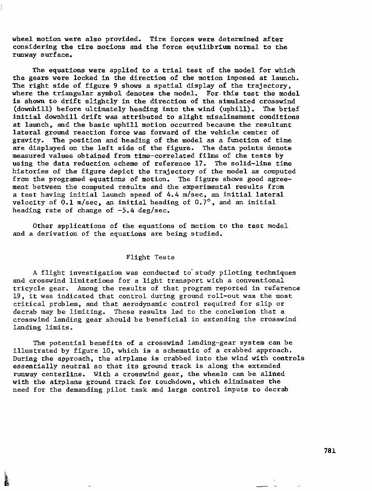
The equations were applied to a trial test of the model for which the gears were locked in the direction of the motion imposed at launch. The right side of figure 9 shows a spatial display of the trajectory, where the triangular symbol denotes the model. For this test the model is shown to drift slightly in the direction of the simulated crosswind (downhill) before ultimately heading into the wind (uphill). The brief initial downhill drift was attributed to slight misalinement conditions at launch, and the basic uphill motion occurred because the resultant lateral ground reaction force was forward of the vehicle center of gravity. The position and heading of the model as a function of time are displayed on the left side of the figure. The data points denote measured values obtained from time-correlated films of the tests by using the data reduction scheme of reference 17. The solid-line time histories of the figure depict the trajectory of the model as computed from the programed equations of motion. The figure shows good agree- ment between the computed results and the experimental results from a test having initial launch speed of 4.4 m/set, an initial lateral velocity of 0.1 mlsec, an initial heading of 0.7O, and an initial heading rate of change of -5.4 deg/sec.
Other applications of the equations of motion to the test model and a derivation of the equations are being studied.
Flight Tests
A flight investigation was conducted to-study piloting techniques and crosswind limitations for a light transport with a conventional tricycle gear. Among the results of that program reported in reference 19, it was indicated that control during ground roll-out was the most critical problem, and that aerodynamic control required for slip or decrab may be limiting. These results-led to the conclusion that a crosswind landing gear should be beneficial in extending the crosswind landing limits.
The potential benefits of a crosswind landing-gear system can be illustrated by figure 10, which is a schematic of a crabbed approach. During the approach, the airplane is crabbed into the wind with controls essentially neutral so that its ground track is along the extended runway centerline. With a crosswind gear, the wheels can be alined with the airplane ground track for touchdown, which eliminates the need for the demanding pilot task and large control inputs to decrab
781
or slip the airplane prior to touchdown. By starting the roll-out with the aerodynamic controls near the neutral datum, the full control range is available for additional control.
The modes of operation chosen to investigate for the crosswind landing-gear flight research program discussed in this paper were based on the previously discussed model studies (ref. 16), and on the experiences gained in the study of reference 18. The test objectives of the cross- wind landing-gear program were to extend the crosswind landing limits of the airplane and to evaluate and demonstrate the effectiveness of lift spoilers and various modes of crosswind landing-gear operation.
Description of system. - The test airplane (fig. 11) was a high- wing, twin turboprop lix transport. A summary sketch of the changes made to the airplane is given in-figure 12. Single main wheels were replaced by the dual wheel units from a military helicopter. Themain gear legs of the transport were inverted and the right and left legs were interchanged. This lowered the airplane ground line by about 15.2 cm (6 in.). Appropriate modifications were also made to the nose gear to account for the lower ground line. The main gear units were physically connected by a metal tie rod to insure that the main gear units were tracking together and to facilitate the centering of the gear. The research crosswind landing-gear system was not optimized for weight, aerodynamics, or operational simplicity.
The wing-lift spoiler system, consisting of two hydraulically- actuated panels on the upper surface of each wing, was automatically limited to deployment at touchdown by means of main gear weight switches in series with an arming switch and a throttle position switch.
The main and nose gear could be pivoted as a unit +30° for cross- wind landings. The nose gear could be steered an additionalk3' about its prevailing position through the rudder pedals. For research purposes, the crosswind landing-gear system was designed to provide the capability of investigating three crosswind landing-gear concepts; The three modes of crosswind landing-gear operation are outlined in table I. In the castor mode, the gear were free to aline with the direction of travel at touchdown. However, to prevent the airplane from veering off the runway, steering must be initiated shortly after touchdown. In the preset mode, the pilot set the gear to the desired offset angle with a tiller bar in the cockpit. (See fig. 13.) (The tiller bar, which controls the pivot angle of the gear, was located on the control column behind the pilot's control wheel, and could also be used to steer the nose gear during low speed taxiing when the main gear were locked.) In the automatic mode, the radio compass system was used to generate an error signal proportional to the angle between a selected runway heading and the airplane heading. This signal, summed with a main-gear position feedback signal, was used to automatically keep the gear alined with the runway centerline while in flight.
782

In the castor and preset modes, the main gear could be locked in position by pressing a switch on the pilot's control wheel. (See fig. 13.) This switch activated a hydraulic castor lock on each main gear unit. In the castor mode, the castor locks would activate when the switch.was depressed and the main gear weight switches were actuated. In the preset mode, the castor locks were actuated in the air in order to lock the gear in position prior to touchdown. In the automatic mode, the gear was locked in position after either of the two main gear weight switches was compressed without the pilot having to press the switch. It should be noted that the main gear must be locked or restrained in order to develop nose-wheel steering capability.
In any mode, after a weight switch on the nose gear had been activated, the pilot could select rudder pedal steering of the nose gear by depressing and holding a thumb switch on the pilot's control wheel. This switch was adjacent to the main gear castor lock switch, as shown in figure 13. The nose-wheel travel with rudder pedal steering was 530. This feature was incorporated to allow the pilot to have limited authority nose-wheel steering for the high-speed part of the ground roll without having to release the control wheel or throttle to reach the tiller bar.
The pilot could also center the gear in any mode by pushing a single switch on the crosswind control panel shown in figure 13. The gear centering command overrode all other inputs or actions. The con- ventional aerodynamic (rudder and aileron) and low-speed nose-wheel steering controls were retained from the original airplane. Main gear braking effectiveness was greatly reduced because hard braking caused flat 'spots or blown tires. Apparently, with the airplane heeling, one of the dual wheels would not carry sufficient load to cvercome brake torque and would be ground flat. Reverse thrust became the principal braking control although very little actual thrust was developed due to the slow engine response.
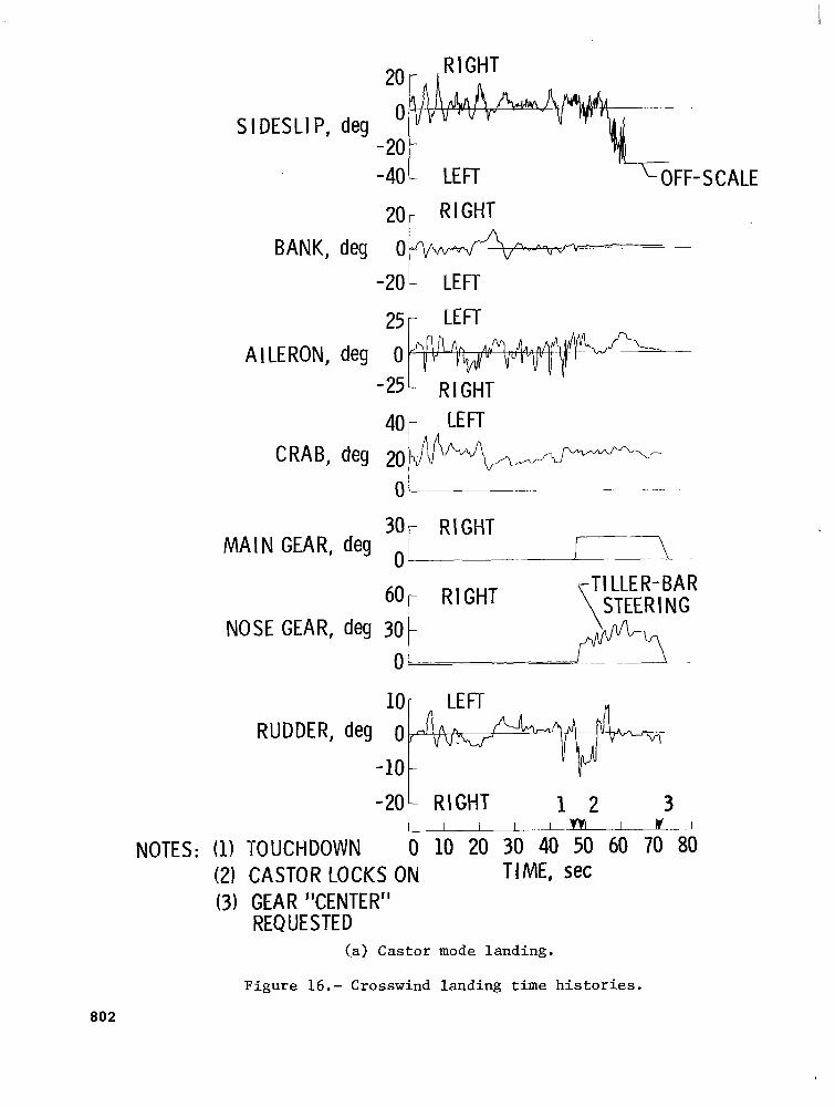
A crosswind landing-gear position indicator was developed for this program. The location of the indicator in the airplane instrument panel is shown in figure 13, and a schematic of the indicator is shown in figure 14. The gyro compass card was driven by a gyro slaved to the compass heading. The double-bar needle pointed to the landing runway magnetic heading, which was input to the system with the runway heading selector knob (part of the horizontal situation indicator on the test airplane). The angular difference between the centerline of the fixed airplane symbol and the runway heading (double-bar needle) was the crab angle of the airplane. The single-bar needle indicated the angle of the gear with respect to the airplane centerline. When the gear were properly alined with the runway centerline, the single-bar and. double-bar
783

needles superimposed. In the example given in figure 14, the runway heading and gear position are purposely shown misalined. The air- plane is shown flying to a heading of 350°, crabbed 15' to the right of runway centerline. The gear are shown offset 20° to the left of :Zirplane: centerline, too far.
which means that the gear have been rotated 5' In the preset mode, the pilot would use the tiller bar in
the cockpit to bring the gear into alinement withthe runway. In the automatic mode, the misalinement would indicate a system malfunction. It is understood that some airplanes with crosswind landing gear have actually landed with the landing gear set in the wrong direction. The use of this indicator should prevent such an occurrence. The pilot csn determine proper wheel alinement from a quick scan without mentally having to process information to relate heading and landing-gear deflection magnitude and direction. Details on the crosswind landing- gear position indicator may be found in reference 19.
Results. - A matrix of the test conditions for this investigation is given in table II. A total of 195 crosswind landings were made in the progrti by three test pilots who used the three modes of crosswind landing-gear operation. The crosswinds given in this paper are the direct crosswind components computed from the wind magnitude and direction recorded at the time of touchdown by a wind sensor at the 6.1-m (20-ft) elevation of a meteorological tower located near the test runways. All landings were made in Visual Flight Rules (VFR) conditions to a dry runway surface. The pilot's task was to land, roll out, and stop the airplane within the STOL runway markings that were painted on the existing runways. The STOL runways were 30.5 m (100 ft) wide and 457 m (1500 ft) long. The markings for these run- ways are given in reference 20. The three runways on which they were painted were 1524 to 2743 m (5000 to 9000 ft) long and 46 to 61 m (150 to 200 ft) wide. The landings were made using a 3O or 6O approach angle, which was indicated by the visual guidance system described in reference 18. All landings were made using full flap deflection and the wing-lift spoilers were used after touchdown for most of the tests.
The pilots have stated that with the crosswind gear "....it is possible to'make crosswind landings in crosswind conditions that are far more severe than could be handled with the conventional gear." With the conventional gear (ref. 18), the crosswind limits were 15 to 20 knots. The largest crosswind encountered during that program was 22 knots, which caused the pilot to abort the landing just prior to touchdown. It can be seen in table II that, with the crosswind gear, 11 landings were made with crosswinds between 20 end 25 knots, and 5 landings were made with crosswinds between 25 and 30 knots. In three
784
tests, the main gear rotated to the right control limits at 30.. The crosswinds of 26 to 27 knots are about one-half the stall,speed of the airplane.
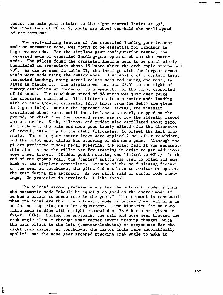
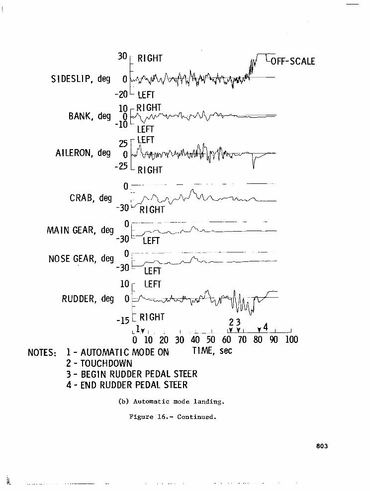
The self-alining feature of the crosswind landing gear (castor mode or automatic mode) was found to be essential for landings in high crosswinds. For the airplane gear configuration tested, the preferred mode of crosswind landing-gear operations was the castor mode. The pilots found the crosswind landing gear to be particularly beneficial in crosswinds above 15 knots where the crab angle approached 2o". As can be seen in table II, the landings with the largest cross- winds were made using the castor mode. A schematic of a typical large crosswind landing, using, actual values measured during one test, is given in figure 15. The airplane was crabbed 23.5O to the right of runway centerline at touchdown to compensate for the right crosswind of 26 knots. The touchdown speed of 58 knots was just over twice the crosswind magnitude. Time histories from a castor mode landing with an even greater crosswind (23.7 knots from the left) are given in figure 16(a). During the approach and landing, the sideslip oscillated about zero, until the airplane was nearly stopped on the ground, at which time the forward speed was so low the sideslip record was off scale. Bank, aileron, and rudder also oscillated about zero. At touchdown, the main and nose gear freely alined with the direction of travel, swiveling to the right (clockwise) to offset the left crab angle. The main gear castor locks were applied 2 set after touchdown, and the pilot used tiller bar steering of the nose gear. Although the pilots preferred rudder pedal steering, the pilot felt it was necessary this time to use the tiller bar for steering in order to get additional nose wheel travel. (Rudder pedal steering was limited to +3O.) At the end of the ground roll, the "center" switch yas used to bring all gear back to the airplane centerline. Because of the self-alining feature of the gear at touchdown, the pilot did not have to monitor or operate the gear during the approach. As one pilot said of castor mode land- ings, "NO precision is involved. I like them."
The pilots' second preference was for the automatic mode, saying the automatic mode "should be equally as good as the castor mode if we had a higher response rate in the gear." This comment is reasonable when one considers that the automatic mode is actively' self-alining in so far as requiring no pilot adjustment. Time histories for an auto- matic mode landing with a right crosswind of 13.6 knots are given in figure 16(b). During the approach, the main and nose gear tracked the crab angle closely through some rather severe heading changes, with the gear offset to the left (counterclockwise) to compensate for the right crab angle. At touchdown, the castor locks were automatically applied, and the nose gear stopped tracking crab angle to make it
785
available for steering. In this landing, the pilot used rudder pedal steering of the nose gear for about 13 sec. The records were terminated before the gear were centered. If, as in the present case, the touch- down forces on the wheels are adequate to aline the gear without pro- ducing an objectionable reaction in the airplane, the castor mode would be preferable to the more complex and expensive automatic mode.
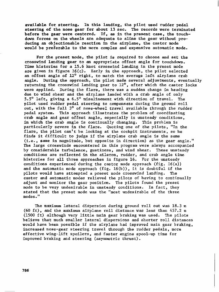
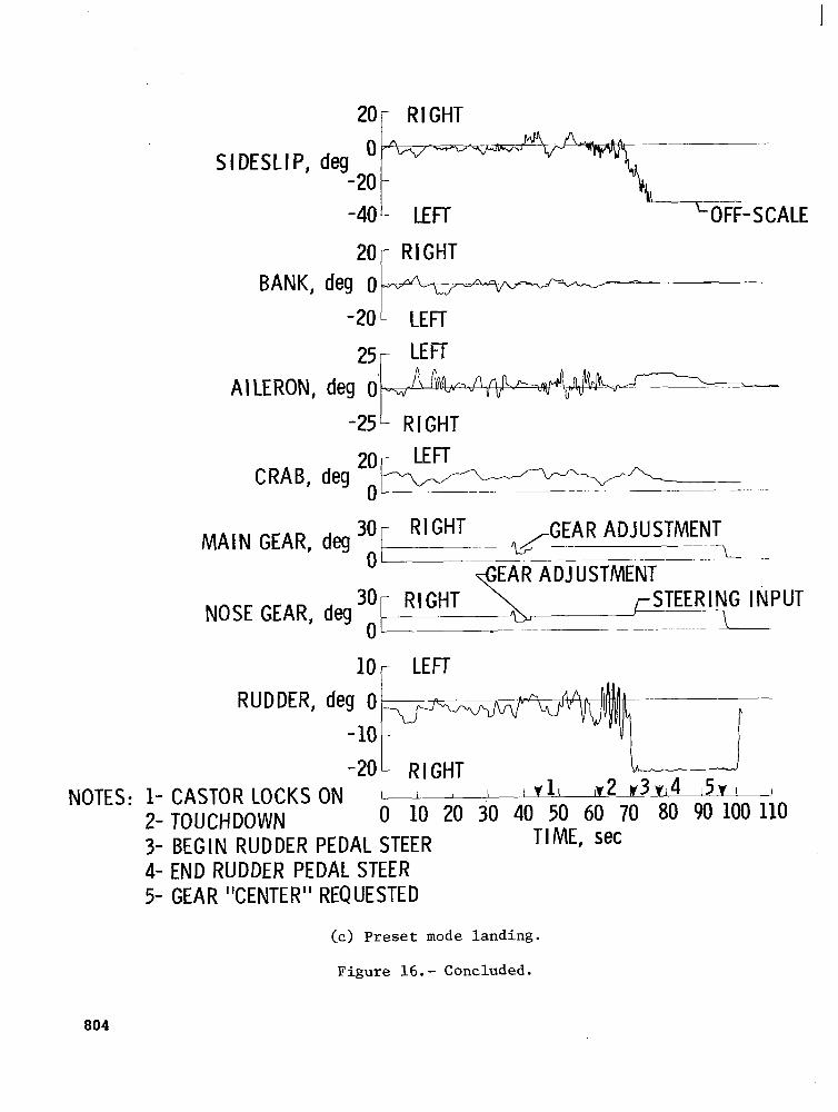
For the preset mode, the pilot is required to choose and set the crosswind landing gear to an appropriate offset angle for touchdown. Time histories for a 15.6 knot crosswind landing in the preset mode are given in figure 16(c). Early in the approach, the pilot selected sn offset angle of 12' right, to match the average left airplane crab angle. During the approach, the pilot made several adjustments, eventually returning the crosswind landing gear to 12', after which the castor locks were applied. During the flare, there was a sudden change in heading due to wind shear and the airplane landed with a crab angle of only 5.5O left, giving a 6.5O misalinement with direction of travel. The pilot used rudder pedal steering to compensate during the ground roll out, with the full 3' of nose-wheel travel available through the rudder pedal system. This approach illustrates the problem of coordinating crab angle and gear offset angle, especially in unsteady conditions, in which the crab angle is continually changing. This problem is particularly severe in the flare. Quoting one of the pilots, "In the flare, the pilot can't be looking at the cockpit instruments, so he finds it difficult to judge if the airplane crab angle is the same (i.e., same in magnitude, but opposite in direction) as the gear angle." The large crosswinds encountered in this program were always accompanied by considerable turbulence, gustiness, and wind shear. These unsteady conditions are reflected in the aileron, rudder, and crab angle time histories for all three approaches in figure 16. For the unsteady conditions experienced during the castor mode approach (fig. 16(a)) and the automatic mode approach (fig. 16(b)), it is doubtful if the pilots would have attempted a preset mode crosswind landing. The castor and automatic modes relieved the pilots of having to continually adjust and monitor the gear position. The pilots found the preset mode to be very undesirable in unsteady conditions. In fact, they stated that the preset mode was the "most undesirable of the three modes.-"
The maximum lateral dispersion during ground roll out was 18.3 m (60 ft), and the maximum airplane roll distance was less than 457.2 m (1500 ft) although very little main gear braking was used. The pilots believe that much smaller lateral dispersions and shorter roll distances would have been possible if the airplane had improved main gear braking, increased nose-gear steering travel through the rudder pedals, more effective wing-lift spoilers, and faster engine spool-up time for improved braking and steering (asymmetric thrust).
786
The pilots feel that greatly improved safety and comfort can be realized by developing an operational castor mode crosswind landing- gear system incorporating castor locks and rudder pedal steering. Side forces would be reduced at touchdown to produce a smooth landing for the passengers. The operation of a crosswind landing gear on slippery runways needs further study, analysis, and/or testing.
CONCLUDING REXARKS
The landing-gear research betng conducted at NASA Langley Research Center is summarized and research relative to tire-tread developments, powered-wheel taxiing, air cushion landing systems, and crosswind landing gear is discussed in some detail. The status of these four programs are as follows:
Tire-tread wear - the preliminary ground tests are complete and flight tests to determine wear characteristics in fleet use are underway
Powered wheels - the prototype is under development
Air cushion landing gear - analysis and experimental tests are underway
Crosswind landing gear - model and flight tests are now complete and equations of motion describing the ground-run trajectory have been derived for a model test
The preliminary results of the crosswind landing-gear flight tests indicated:
1. Landings can be made with crosswinds up to 27 knots with a crosswind landing gear; the previous crosswind limits with the conventional tricycle landing gear were 15 to 20 knots.
2. For the light transport airplane tested, the self-alining feature of the crosswind landing gear was found to be essential for landing in severe crosswinds.
3. The castor mode (passive self-alinement) was preferred by the pilots; presetting the landing gear prior to touch- down was the least desirable of the three modes of operation that were investigated.
787

REFERENCES
1.
2.
3.
4.
5.
6.
7.
8.
9.
10.
11.
Stubbs, Sandy M.; and Tanner, John A.: Status of Recent Aircraft Braking and Cornering Research. Aircraft Safety and Operating Problems, NASA SP-416, 1976, pp. 257-269.
McDonnell Aircraft Co.: Expansion of Flight Simulator Capability for Study and Solutionof Aircraft Directional Control Problems on Runways. Phase II 7 Final Report. NASA CR-145044, 1976.
Stubbs, Sandy M.; and Tanner, John A.: Behavior of Aircraft Anti- skid Braking Systems on Dry and Wet Runway Surfaces - A Velocity- Rate-Controlled, Pressure-Bias-Modulated System. NASA TN D-8332, 1976.
Tanner, John A.; and Stubbs, Sandy M.: Behavior of Aircraft Anti- skid Braking Systems on Dry and Wet Runway Surfaces - A Slip- Ratio-Controlled System With Ground Speed Reference From &braked Nose Wheel. NASA TN D-8455, 1977.
Bender, E. K.; Berkman, E. F.; and Bieber, M.: A Feasibility Study of Active Landing Gear. AFFDL-TR-70-126, U.S. Air Force, July 1971. (Available from DDC as AD 887 451L).
Wignot, Jack E.; Durup, Paul C.; and Gamon, Max A.: Design Formu- lation and Analysis of an Active Landing Gear. Volume I. Analysis, AFFDL-TR-71-80, Vol. I, U.S. Air Force, Aug. 1971. (Available from DDC as AD 887 127L.)
McGehee, John R.; and Carden, Huey D.: A Mathematical Model of an Active Control Landing Gear for Load Control During Impact and Roll-Out. NASA TN D-8080, 1976.
Barrois, W.: Use of General Fatigue Data in the Interpretation of Full-Scale Fatigue Tests. AGARD-AG228, Oct. 1977, pp. 62-64.
Dreher, Robert C.: Studies of Friction and Wear Characteristics of Various Wires for Wire-Brush Skids. NASA TN D-8517, 1977.
Home, Walter B.: Status of Runway Slipperiness Research. Air- craft Safety and Operating Problems, NASA SP-416, 1976, pp. 191-245.
Yager, Thomas J.; and McCarty, John L.: Friction Characteristics of Three 30 x 11.5-14.5, Type VIII, Aircraft Tires With Various Tread Groove Patterns and Rubber Compounds. NASA TP-1080, 1977.
788
12.
13.
14.
15.
16.
17.
18.
19.
20.
Leland, Trafford J. W.; and Thompson, William C.: Landing-Impact Studies of a 0.3-Scale Model Air Cushion Landing System for a Navy Fighter Airplane. NASA TN D-7875, 1975.
Thompson, William C.: Landing Performance of an Air-Cushion Landing System Installed on a l/lo-Scale Dynamic Model of the C-8 Buffalo Airplane. NASA TN D-7295, 1973.
Thompson, William C.; Boghani, Ashok B.; and Leland, Trafford J.W.: Experimental and Analytical Dynamic Flaw Characteristics of an Axial-Flow Fan From an Air Cushion Landing System Model. NASA TN D-8413, 1977.
Boghani, A. B.; Captain, K. M.; and Wormley, D. N.: Heave-Pitch- Roll Analysis and Testing of Air Cushion Landing Systems. NASA CR-7917, 1978.
Stubbs, Sandy M.; Byrdsong, Thomas A.; and Sleeper, Robert K.: An Experimental Simulation Study of Four Crosswind Landing- Gear Concepts. NASA TN D-7864, 1975.
Sleeper, Robert K.; and Smith, Eunice G.: A Transformation Method for Deriving From a Photograph, Position and Heading of a Vehicle in a Plane. NASA TN D-8201, 1976.
Fisher, Bruce D.; Champine, Robert A.; Deal, Perry L.; Patton, James M., Jr.; and Hall, Albert W.: A Flight Investigation of Piloting Techniques and Crosswind Limitations During Visual STOL-Type Landing Operations. NASA TN D-8284, 1976.
Champine, Robert A.: Crosswind Landing-Gear Position Indicator. NASA Tech Brief LAR-11941, 1976.
Spangler, Roman M., Jr.: Simulated Ground-Level STOL Runway/ Aircraft Evaluation. FAA-RD-73-110, Federal Aviation Administra- tion, Sept. 1973.
789

TABLE I. - MODES OF OPERATION FOR CROSSWIND RESEARCH
Mode
Castor
Preset Pilot control during approach
Crab set of gear
Passively - by ground forces during touchdown
Automatic Servo driven by signals from aircraft heading and runway direction
Ground control
In addition to conventional aerodynamic, brake, and low-speed nose-wheel steering control, the pilot can select:
1. Nose-wheel steering at high speed through rudder pedals
2. Wing-lift spoilers
3. Return gear to center
4. Preset crab angle for take-off
Approach m31es deg
Number of landings for each 5-knot Crosswind crosswind interval mode
-3
-3
-3
-6
-6
-6
0 to 5 5 to 10 10 to 15 15 to 20 20 to 25 25 to 30
4 20 37 45 11 5 Castor
0 17 20 5 0 0 Automatic
0 11 11 4 0 0 Preset
1 3 0 0 0 0 Castor
0 1 0 0 0 0 Automatic
0 0 0 0 0 0 Preset
TABLE II. - MATRIX OF TEST CONDITIONS RECORDED FOR 195 LANDINGS
F i g u r e 1.- A i r c r a f t l and ing l o a d s and t r a c t i o n f a c i l i t y .
F i g u r e 2.- I n s t r u m e n t e d t i r e test v e h i c l e ,

F R I C T I O N COEFF I C I ENS
V&AR RATE
I /NATURAL RUBBER
/ EX PE R l MENTAL
ART
Figure 3.- Low-speed friction and wear characteristics of several tire-tread compositions.
F i g u r e 4 , - Powered wheel h y d r a u l i c motor.
793
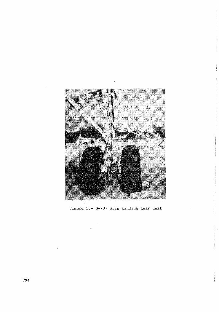
Figure 5.- B-737 main landing gear u n i t .
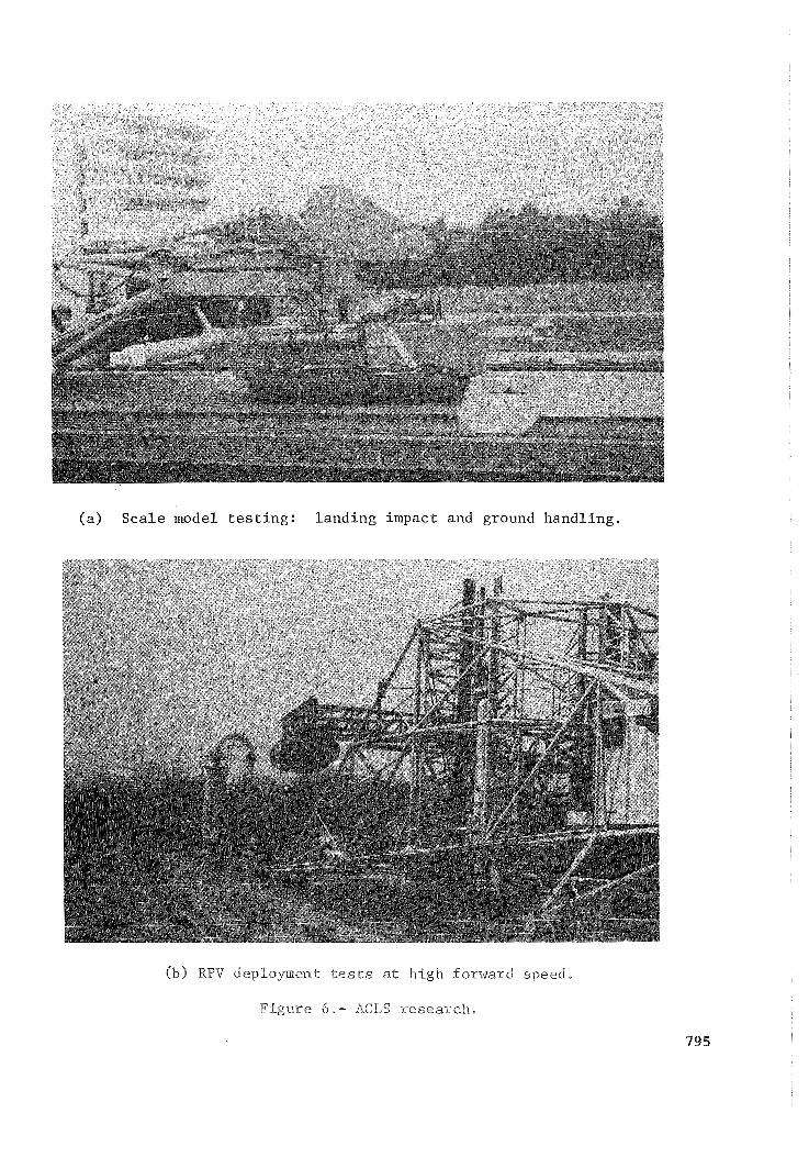
( a ) S c a l e model t e s t i n g : l a n d i n g impact and ground hand l ing .
(b) RPV deploymimt tests at high forward speed.
Figure 6,- ACLS research,
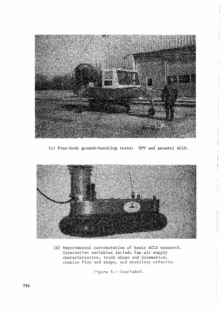
( c ) Free-body ground-handling t e s t s : RPV and g e n e r a l ACLS.
(d) Exper imental c o r r o b o r a t i o n of b a s i c ACLS r e s e a r c h . I n t e r a c t i v e v a r i a b l e s i n c l u d e f a n a i r s u p p l y c h a r a c t e r i s t i c s , t r u n k shape and k i n e m a t i c s , cushion f low and shape , and s t a b i l i t y c r i t e r i a .
F i g u r e 6 . - Concluded.

P I T C H ATTITUDE - Oo
ANALYS l S . EXPERIMENT
15 - VERTl CAL
EXPERIMENT
10 in. c m
5
0
-2 -5 I I
0 1 2 3 0 1 ? 3 I
TIME, sec -
TIME, ser:
Figure 7.- V e r i f i c a t i o n of dynamic ACLS model a n a l y s i s ; heave ( v e r t i c a l ) motion only. P i t c h a t t i t u d e = 0'.
F i g u r e 8.- C r o s s w i n d m o d e l t es t .

1.0 r
-10 0 .5 1.0 1.5 2.0 2.5 - .
TIME, set LATERAL DISTANCE, x, m
Figure 9.- Computed ground roll trajectory of landing-gear model.
GROUNDTRACK
CROS
RUNWAY
0 0
Figure lO.- Schematic of typical crosswind landing with crosswind gear.
798
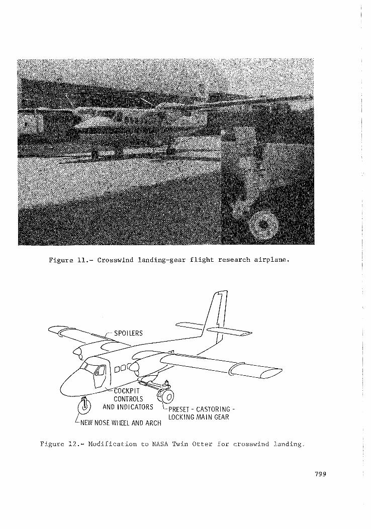
Figu re 11.- Crosswind landing-gear f l i g h t r e sea rch a i r p l a n e .
AND INDICATORS FRESET - CASTORING - LOCKING M A I N GEAR
F i g u r e 1 2 . - M o d i f i c a t i o n t o NASA Twin Otter f o r crosswind l a n d i n g .
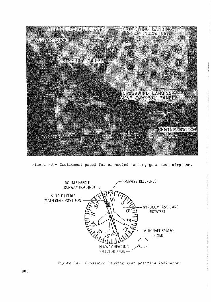
Figure 13.- Instrument panel for crosswind Landing-gear test airplane.
DOUBLE NEEDLE /-COMPASS REFERENCE (RUNWAY HEADING)-,
NGLE NEEDLE GEAR POSITION)
GYROCOMPASS CARD (ROTATES
AIRCRAFT SYMBOL (FIXED)
RUNWAY HEADING SELECTOR KNOB-J'
F i g u r e 1 4 . - Crosswind landing-gear p o s i r i o n i n d i c a t o r ,

I r RUNWAY CENTERLINE --- --- -
26knots CROSSWIND 58 knots Al RSPEED
Figure 15.- A Z&knot crosswind landing with crosswind gear.
801
S I DESLI P, deg
BANK, deg
A I LERON, deg
20 RIGHT
0
20 40
20- RIGHT
0 J+%%-*~-v*~A-- -- _- ~
20- LEFT
-2% RI GHT
40 CRAB, deg 20
0
MAIN GEAR, deg 3:r- 1----7- 60 RIGHT
NOSE GEAR, deg 30
RUDDER, deg
NOTES: (I.1 (2) (3)
-20L RIGHT 12 3 I I I I I WI I w .I
TOUCHDOWN 0 10 20 30 40 50 60 70 -iO CASTOR LOCKS ON TIME, set GEAR “CENTER” REQUESTED
(.a> Castor mode landing.
Figure 16.- Crosswind landing time histories.
802
SIDESLIP, deg 0
FF- SCALE
-20L LEFT
BANK, deg _
Al LERON, deg
CRAB, deg
MAIN GEAR, deg
GEAR, deg ’ - ~~-~ ._.. ..-
NOSE -30 10 - LEFT
RUDDER, deg 0 w?yh-
e15 I RIGHT LVI- 1 I I_~ L -I f?, y4 , I
0 10 20 j0 40 50 60 70 80 90 100 NOTES: 1 - AUTOMATIC MODE ON TIME, set
2 - TOUCHDOWN 3 - BEGIN RUDDER PEDAL STEER 4 - END RUDDER PEDAL STEER
(b) Automatic mode landing.
Figure 16.- Continued.
803
2Or RIGHT 0 +q,/ -
SIDESLIP, deg -20 - -4O- LEFT 'OOFF-SCALE
20- RIGHT BANK, deg 00 -
-20- LEFT
25- I-En AILERON, deg o'+~A h,m-uVvkk
-25- RIGHT LEFT
CRAB, deg 2~~-.---~. _. ..-
MAIN GEAR, deg 3($Ed.-1_/GEAR ADJUSTME!!L - -.-~ GEAR ADJUSTMENT
NOSE GEAR, deg 30- RIGHT \ rSTEERING IklPUT 0 ----
1°r LEFT
RUDDER, deg 0
-lO- -2DL RIGHT I
NOTES: l- CASTOR LOCKS ON 1 I I I I rl, n2 tv3r,4 ,5r I , 2-TOUCHDOWN 0 10 20 30 40 50 60 70 80 90 100 110 3- BEGIN RUDDER PEDAL STEER TIME, set 4-END RUDDER PEDAL STEER 5- GEAR"CENTER"REQUESTED
(c) Preset mode landing.
Figure 16.- Concluded.
804