SDM-8000 SATELLITE MODEM...SDM-8000 Satellite Modem Installation and Operation Manual Filename:...
370
Part Number MN/SDM8000.IOM Revision 12 SDM-8000 Satellite Modem Installation and Operation Manual
Transcript of SDM-8000 SATELLITE MODEM...SDM-8000 Satellite Modem Installation and Operation Manual Filename:...

Part Number MN/SDM8000.IOM Revision 12
SDM-8000Satellite Modem
Installation and Operation Manual


Filename: T_ERRATA 1
Errata A Comtech EFData Documentation Update
Subject: Added Modulator Configuration Board PL/5039- 1 through –8, and PL/5039-11 through -18
Date: February 6, 2001 Document: SDM-8000 Satellite Data Modem Installation and Operation
Manual, Rev. 12, dated August 6, 1999 Part Number: MN/SDM8000.EAC Collating Instructions: Attach this page to page 1-10 Comments:
The following changes provide updated information for Table 1-3. This information will be incorporated into the next revision.
Change Specifics: Change Table 1-3 to read as follows:

Filename: T_ERRATA 2
Table 1-3. Modem Assemblies
Drawing # Assembly Remarks PL/2300-1 Assy, Top EIA-8000 Kit, Reed-Solomon PL/3606-1 Chassis, SDM-8000 AC PL/3606-2 Chassis, SDM-8000 DC PL/2305 Display/Monitor & Control No FW required PL/2487 Extender Board PL/2876 Interface Switch Relay Board Optional Daughter Board PL/5039-1 Modulator Card 50Ω Repls 3415-1 PL/5039-2 Modulator Card 75Ω Repls 3415-2 PL/5039-3 Modulator Card 50Ω, +5 dBm Repls 3415-3 PL/5039-4 Modulator Card 75Ω, +5 dBm Repls 3415-4 PL/5039-5 Modulator Card 50Ω, High Stability Option Repls 3415-5 PL/5039-6 Modulator Card 75Ω, High Stability Option Repls 3415-6 PL/5039-7 Modulator Card 50Ω, High Stability Option (+5 dBm) Repls 3415-7 PL/5039-8 Modulator Card 75Ω, High Stability Option (+5 dBm) Repls 3415-8 PL/5039-11 Modulator Card 50Ω, 8PSK/16QAM Repls 3415-11 PL/5039-12 Modulator Card 75Ω, 8PSK,/16QAM Repls 3415-12 PL/5039-13 Modulator Card 50Ω, +5 dBm 8PSK/16QAM Repls 3415-13 PL/5039-14 Modulator Card 75Ω, +5 dBm 8PSK/16QAM Repls 3415-14 PL/5039-15 Modulator Card 50Ω, High Stability Option 8PSK/16QAM Repls 3415-15 PL/5039-16 Modulator Card 75Ω, High Stability Option 8PSK/16QAM Repls 3415-16 PL/5039-17 Modulator Card 50Ω, High Stability Option (+5 dBm)
8PSK/16QAM Repls 3415-17
PL/5039-18 Modulator Card 75Ω, High Stability Option (+5 dBm) 8PSK/16QAM
Repls 3415-18
PL/4895-1 Demodulator Card Viterbi 50Ω 8PSK/QPSK Repls PL3416-1 PL/4895-2 Demodulator Card Viterbi 75Ω 8PSK/QPSK Repls PL3416-2 PL/4895-3 Demodulator Card Viterbi 50Ω 8PSK/16QAM Repls PL3416-3 PL/4895-4 Demodulator Card Viterbi 75Ω 8PSK/16QAM Repls PL3416-4 PL/4895-5 Demodulator Card Viterbi/Sequential 50Ω 8PSK/QPSK Repls PL3416-1 PL/4895-6 Demodulator Card Viterbi/Sequential 75Ω 8PSK/QPSK Repls PL3416-2 PL/4895-7 Demodulator Card Viterbi/Sequential 50Ω 8PSK/16QAM Repls PL3416-3 PL/4895-8 Demodulator Card Viterbi/Sequential 75Ω 8PSK/16QAM Repls PL3416-4 PL/3495-1 Interface Card (Standard) PL/3495-2 Interface Card (Standard with Buffer) PL/3495-3 Interface Card (IBS) PL/3495-4 Interface Card (IBS/IDR) PL/3708-1 Reed-Solomon Board (IDR Standard) Optional Daughter Board PL/3117 Sequential Decoder Board Optional Daughter Board PL/3496-1 ASYNC/AUPC Board Optional Daughter Board PL/3496-2 Drop & Insert with ASYNC/AUPC Board Optional Daughter Board
Note: All the high stability modulators have the capability of having the SCT INTERNAL synthesized to the EXT CLOCK input at the data I/O connector. This is used in asymmetrical Loop Timing applications. (See Chapter 5.)
Filename: T_ERRATA 1
Errata B Comtech EFData Documentation Update
Subject: Change Paragraph 3.2 Date: February 6, 2001 Document: SDM-8000 Satellite Data Modem Installation and Operation
Manual, Rev. 12, dated August 6, 1999 Part Number: MN/SDM8000.EBC Collating Instructions: Attach this page to page 3-4 Comments:
The following changes provide updated information for paragraph 3.2. This information will be incorporated into the next revision.
Change Specifics:
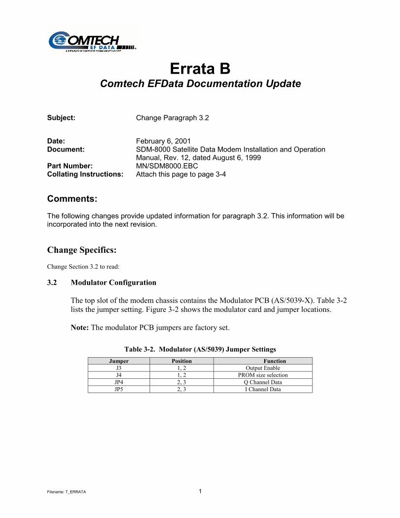
Change Section 3.2 to read: 3.2 Modulator Configuration
The top slot of the modem chassis contains the Modulator PCB (AS/5039-X). Table 3-2 lists the jumper setting. Figure 3-2 shows the modulator card and jumper locations. Note: The modulator PCB jumpers are factory set.
Table 3-2. Modulator (AS/5039) Jumper Settings Jumper Position Function
J3 1, 2 Output Enable J4 1, 2 PROM size selection
JP4 2, 3 Q Channel Data JP5 2, 3 I Channel Data

Filename: T_ERRATA 2
Figure 3-2. Modulator (AS/5039) PCB
JP5
JP4
J3
J4
JP4
JP5
J3
J4
MODULATOR BOARDAssembly Number
& Revision
Filename: T_ERRATA 1
Errata C Comtech EFData Documentation Update
Subject: Added Demodulator Configuration Board PL/4895-1 through -8 Date: February 6, 2001 Document: SDM-8000 Satellite Data Modem Installation and Operation
Manual, Rev. 12, dated August 6, 1999 Part Number: MN/SDM8000.ECC Collating Instructions: Attach this page to page 3-6 Comments:
The following changes provide updated information for paragraph 3.3. This information will be incorporated into the next revision.
Change Specifics:
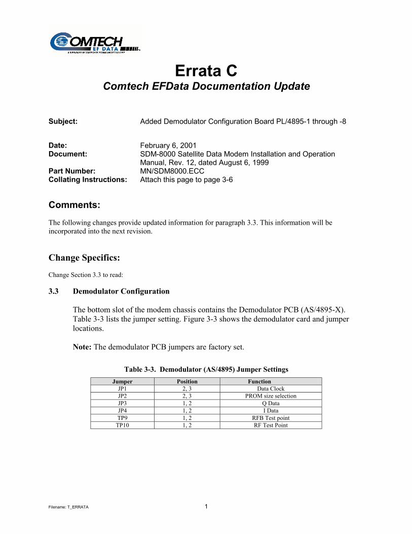
Change Section 3.3 to read: 3.3 Demodulator Configuration
The bottom slot of the modem chassis contains the Demodulator PCB (AS/4895-X). Table 3-3 lists the jumper setting. Figure 3-3 shows the demodulator card and jumper locations. Note: The demodulator PCB jumpers are factory set.
Table 3-3. Demodulator (AS/4895) Jumper Settings Jumper Position Function
JP1 2, 3 Data Clock JP2 2, 3 PROM size selection JP3 1, 2 Q Data JP4 1, 2 I Data TP9 1, 2 RFB Test point
TP10 1, 2 RF Test Point

Filename: T_ERRATA 2
Figure 3-3. Demodulator (AS/4895) PCB
JP1
JP2
TP 9
TP 10
JP 3
JP 4
JP2
JP1
DEMODULATOR BOARDAS/4895 REV _________S/N _________________

Filename: T_ERRATA 1
Errata D Comtech EFData Documentation Update
Subject: Add paragraph 3.7 8PSK 2/3 IESS310 Operation Date: January 29, 2001 Document: SDM-8000 Satellite Data Modem Installation and Operation
Manual, Rev. 12, dated August 6, 1999 Part Number: MN/SDM8000.EDC Collating Instructions: Attach this page to page 3-24 Comments:
The following addition is provide for SDM-8000 Configuration. This information will be incorporated into the next revision.
Change Specifics:
Add Section 3.7 to read: 3.7 8PSK 2/3 IESS Operation
Whenever IESS310 mode is turned Off the Reed-Solomon parameters (N/K/T/I) used are the same as usual. When IESS310 mode is turned On, new Reed-Solomon parameters are used (8PSK 2/3 only). Refer to Table 3-1of Reed-Solomon parameters used on the SDM-8000 modem. The user interface changes on the modem include new menus located in the Utility Modulator and Demodulator. The menus are named: “TX IESS-310 MODE” and RX IESS-310 MODE.” They are displayed at all times to allow flexibility for the user to make modem changes in any order. Also, there are new remote commands and reworked commands for switch support and M&C system (“BCS_”).
Filename: T_ERRATA 2
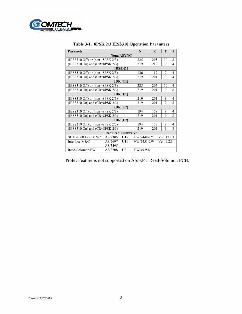
Table 3-1. 8PSK 2/3 IESS310 Operation Paramters
Parameter N K T I None/ASYNC
(IESS310 Off) or (non –8PSK 2/3) 225 205 10 8 (IESS310 On) and (CR=8PSK 2/3) 219 210 9 4
IBS/D&I (IESS310 Off) or (non –8PSK 2/3) 126 112 7 4 (IESS310 On) and (CR=8PSK 2/3) 219 201 9 4
IDR (T1) (IESS310 Off) or (non –8PSK 2/3) 225 205 10 4 (IESS310 On) and (CR=8PSK 2/3) 219 201 9 8
IDR (E1) (IESS310 Off) or (non –8PSK 2/3) 219 201 9 4 (IESS310 On) and (CR=8PSK 2/3) 219 201 9 8
IDR (T2) (IESS310 Off) or (non –8PSK 2/3) 194 178 8 4 (IESS310 On) and (CR=8PSK 2/3) 219 201 9 8
IDR (E2) (IESS310 Off) or (non –8PSK 2/3) 194 178 8 4 (IESS310 On) and (CR=8PSK 2/3) 219 201 9 8
Required Firmware: SDM-8000 Host M&C AS/2305 U17 FW/2448-1Y Ver: 17.1.1 Interface M&C AS/2697
AS/3495 U111 FW/2451-2W Ver: 9.2.1
Reed-Solomon FW AS/3708 U8 FW/4925D
Note: Feature is not supported on AS/3241 Reed-Solomon PCB.

Filename: T_ERRATA 1
Errata E Comtech EFData Documentation Update
Subject: Changes to Chapter 3 (Utility Modulator and Demodulator Menus) Changes to Appendix A (Remote Control Operation)
Date: May 25, 2001 Part Number: MN/SDM8000.EEC Related Document: SDM-8000 Satellite Modem Installation and Operation Manual,
Revision 12, August 6, 1999, Part Number: MN/SDM8000.IOM Collating Instructions: Attach this page to page 4/45 of MN/SDM8000.IOM Comments:
The following changes provide updated information for Sections:
1. 4.3.11.1, Utility Modulator Menu, and 2. 4.3.11.2, Utility Demodulator Menu.
Remote Commands
1. A.3.1 Modulator Menu 2. A.3.2 Demodulator Menu
This information will be incorporated into the next revision.
Change Specifics:
1. The CSC CLOSED transmit or receive filter type is not compatible with a Sequential encoder or decoder type and a 3/4 code rate.
2. The CSC CLOSED Modulator or Demodulator type is compatible with the 1/2 and 7/8
code rates for a Sequential encoder or decoder. For Remote Commands
1. See Note for MET command
2. The CSC mod/demod type is not compatible with the combination of a Sequential encoder or decoder type and a 3/4 code rate.
Changed pages follow.

Filename: T_ERRATA 2
4.3.11.1 Utility Modulator Refer Figure 4-15
ASSIGN TRANSMIT FILTERS
Transmit filter display/assignment utility. Used to make filter rate reassignments. The modulator has five symbol rate filter presets designated as A, B, C, D, and V. Viterbi Sequential Code Rate Data Rate Range Data Rate Range BPSK 1/2 9.6 to 3150.OK 9.6 to 1544.0K QPSK 1/2 19.0 to 6300.0K 19.0 to 2185.0K QPSK 3/4 28.5 to 9312.0K 28.5 to 3277.0K QPSK 7/8 33.25 to 9312.0K 33.25 to 3823.0K 8PSK 2/3 38.0 to 9312.0K Not Applicable 8PSK 5/6 47.5 to 9312.0K Not Applicable 16QAM 3/4 57.0 to 9312.0K Not Applicable 16QAM 7/8 64.0 to 9312.0K Not Applicable QPSK 1/1 38.0 to 9312.0K Not Applicable Note:
1. Switching between modem types resets the filter presets to their factory defined values.
2. Code Rate 3/4 not compatible with a combination of a CSC Closed Modulator Type and Sequential Encoder
To view the current preset assignments, press [ENTER]. TX-A will be on line 1 of the display, followed by the code rate (1/2, 3/4, or 7/8). On line 2 will be the data rate assigned to preset A. Press [←] or [→] to view the assignments for presets B, C, D, and V (TX-B, TX-C, TX-D, and TX-V). To change a preset assignment, press [ENTER] when the data for that preset is displayed. Press [←] or [→] until the flashing cursor is at the parameter to be changed, then [↑] or [↓] to change that parameter. After all changes have been made, press [ENTER] to confirm the assignment. If a preset data/code rate is changed and the modem is currently using that preset, the modem will be reprogrammed to the new data/code rate.
MOD POWER OFFSET Modulator power offset adjust. Offsets the modulator output power readout in the Configuration menu. This feature does not actually change the modulator power level, but displays an offset value in the monitor. The modulator power offset range is -49.9 to +49.9 dB, in 0.1 dB steps. Note: Anything except 0.0 dB will cause ADJ to be displayed in the TX power level screen.
MOD POWER FIXED OFFSET
Modulator power offset (status only). Indicates the power of a modulator that has been provided with extra gain (+20.0 to -20.0 dBm). Note: This screen displays the fixed modulator power offset for Nominal High Power options.
MODULATOR TYPE Transmit filter type select. Select INTELSAT OPEN, EFD CLOSED, CSC CLOSED, or FDC CLOSED network filtering. Note:
1. CSC CLOSED Modulator Type is not compatible with a 3/4 Code Rate and Sequential Encoder Type combination.
ENCODER TYPE Encoder type selection. Select Viterbi or Sequential encoder type. Note:
1. A Sequential Encoder Type and a 3/4 Code Rate combination is not compatible with a CSC Closed Modulator Type.

Filename: T_ERRATA 3
TX MODULE FW Displays the transmit module firmware version. The display includes the month, day, and year.
TX FPGA FIRMWARE Displays the firmware installed in the TX field programmable gate array. The display includes the month, day, and year.
MOD SPECTRUM Programmable vector rotation. Allows the operator to select Normal or Inverted (INVERT) for spectrum reversal of the I and Q baseband channels.
TX IESS-310 MODE Programs the IESS-310 On or Off. Used for 8PSK 2/3 and Reed-Solomon. On entry, the current status is displayed. Press an arrow key to make the selection. Press [ENTER] to execute the change.
Filename: T_ERRATA 4
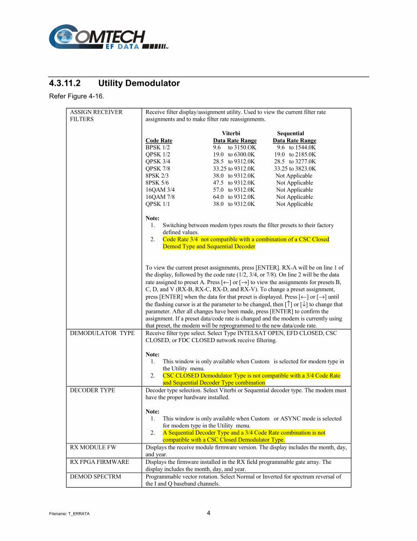
4.3.11.2 Utility Demodulator Refer Figure 4-16.
ASSIGN RECEIVER FILTERS
Receive filter display/assignment utility. Used to view the current filter rate assignments and to make filter rate reassignments. Viterbi Sequential Code Rate Data Rate Range Data Rate Range BPSK 1/2 9.6 to 3150.OK 9.6 to 1544.0K QPSK 1/2 19.0 to 6300.0K 19.0 to 2185.0K QPSK 3/4 28.5 to 9312.0K 28.5 to 3277.0K QPSK 7/8 33.25 to 9312.0K 33.25 to 3823.0K 8PSK 2/3 38.0 to 9312.0K Not Applicable 8PSK 5/6 47.5 to 9312.0K Not Applicable 16QAM 3/4 57.0 to 9312.0K Not Applicable 16QAM 7/8 64.0 to 9312.0K Not Applicable QPSK 1/1 38.0 to 9312.0K Not Applicable Note:
1. Switching between modem types resets the filter presets to their factory defined values.
2. Code Rate 3/4 not compatible with a combination of a CSC Closed Demod Type and Sequential Decoder
To view the current preset assignments, press [ENTER]. RX-A will be on line 1 of the display, followed by the code rate (1/2, 3/4, or 7/8). On line 2 will be the data rate assigned to preset A. Press [←] or [→] to view the assignments for presets B, C, D, and V (RX-B, RX-C, RX-D, and RX-V). To change a preset assignment, press [ENTER] when the data for that preset is displayed. Press [←] or [→] until the flashing cursor is at the parameter to be changed, then [↑] or [↓] to change that parameter. After all changes have been made, press [ENTER] to confirm the assignment. If a preset data/code rate is changed and the modem is currently using that preset, the modem will be reprogrammed to the new data/code rate.
DEMODULATOR TYPE Receive filter type select. Select Type INTELSAT OPEN, EFD CLOSED, CSC CLOSED, or FDC CLOSED network receive filtering. Note:
1. This window is only available when Custom is selected for modem type in the Utility menu.
2. CSC CLOSED Demodulator Type is not compatible with a 3/4 Code Rate and Sequential Decoder Type combination
DECODER TYPE Decoder type selection. Select Viterbi or Sequential decoder type. The modem must have the proper hardware installed. Note:
1. This window is only available when Custom or ASYNC mode is selected for modem type in the Utility menu.
2. A Sequential Decoder Type and a 3/4 Code Rate combination is not compatible with a CSC Closed Demodulator Type.
RX MODULE FW Displays the receive module firmware version. The display includes the month, day, and year.
RX FPGA FIRMWARE Displays the firmware installed in the RX field programmable gate array. The display includes the month, day, and year.
DEMOD SPECTRM Programmable vector rotation. Select Normal or Inverted for spectrum reversal of the I and Q baseband channels.

Filename: T_ERRATA 5
RX IESS-310 MODE Programs the IESS-310 On or Off. Used for 8PSK 2/3 and Reed-Solomon. On entry, the current status is displayed. Press an arrow key to make the selection. Press [ENTER] to execute the change.
REMOTE CONTROL OPERATION A.3.1 Modulator Modulator Frequency
Command: Response: Status: Response:
<add/MF_nnn.nnnn'cr' >add/MF_nnn.nnnn'cr' RF_OFF'cr''lf'] <add/MF_'cr' >add/MF_nnn.nnnn'cr''lf']
Where: nnn.nnnn = Frequency in MHz, 50.0000 to 90.0000, and 100.0000 to 180.0000, in 2.5 kHz steps. Note: When the modulator frequency is programmed, the RF output is switched off.
RF Output (IF Output)
Command: Response: Status: Response:
<add/RF_xxx'cr' >add/RF_xxx'cr''lf'] <add/RF_'cr' >add/RF_xxx'cr''lf']
Where: xxx = ON or OFF.
Modulator Rate Preset Assignment
Command: Response: Status: Response:
<add/AMRx_nnnnn_mmmm.mmm'cr' >add/AMRx_nnnnn_mmmm.mmm'cr''lf'] <add/AMRx_'cr' >add/AMRx_nnnnn_mmmm.mmm'cr''lf']
Where:
x = A, B, C, D, or V (Preset designator). nnnnn = one of the following Coder rates: 1/2 (QPSK 1/2), 3/4 (QPSK 3/4), 7/8 (QPSK 7/8), BP12 (BPSK 1/2), 8P23 (8PSK 2/3), 8P56 (8PSK 5/6), 16Q34 (16QAM 3/4), 16Q78 (16QAM 7/8), QPSK (QPSK 1/1). mmmm.mmm = Data rate in kHz. See Note for MET command
Modulator Rate Preset Selection
Command: Response: Status:
<add/SMRx_'cr' >add/SMRx_'cr' RF_OFF'cr''lf'] See MR command.
Where: x = A, B, C, D, or V (Preset designator). Note: Setting the modulator rate turns off the RF transmitter.
Modulator Rate Variable Assignment & Selection
Command: Response: Status:
<add/SMRV_nnnnn_mmmm.mmm'cr' >add/SMRV_nnnnn_mmmm.mmm'cr' RF_OFF'cr''lf'] See MR command.
Where:
nnnnn = one of the following Coder rates: 1/2 (QPSK 1/2), 3/4 (QPSK 3/4), 7/8 (QPSK 7/8), BP12 (BPSK 1/2), 8P23 (8PSK 2/3), 8P56 (8PSK 5/6), 16Q34 (16QAM 3/4), 16Q78 (16QAM 7/8), QPSK (QPSK 1/1). mmmm.mmm = Data rate in kHz.
See Note for MET command Note: Setting the modulator turns off the RF transmitter.
Set Modulator Power Offset
Command: Response: Status: Response:
<add/MPO_snn.n'cr' >add/MPO_snn.n'cr''lf'] <add/MPO_'cr' >add/MPO_snn.n'cr''lf']
Where: snn.n = +99.9 to -69.9, in 0.1 dB increments. Note: The modulator power offset is added to the nominal power level to adjust the transmit power range.

Filename: T_ERRATA 6
Set Modulator Output Power Level
Command: Response: Status: Response:
<add/MOP_snn.n'cr' >add/MOP_snn.n'cr''lf'] <add/MOP_'cr' >add/MOP_snn.n'cr''lf']
Where: snn.n = -30.0 to -5.0, in 0.1 steps (nominal range in dBm). Notes:
1. The nominal power range is modified relative to the value specified by the modulator power offset (MPO_).
2. When TX Overhead is programmed for ASYNC, AUPC is installed, and AUPC local power enable 'LPC_' is programmed 'ON'; the MOP (Modulator Output Power) command is not allowed. Only MOP status is allowed. See 'LPC_' command.
Scrambler Enable
Command: Response: Status: Response:
<add/SE_xxx'cr' >add/SE_xxx'cr''lf'] <add/SE_'cr' >add/SE_xxx'cr''lf']
Where: xxx = ON or OFF.
Differential Encoder Enable
Command: Response: Status: Response:
<add/DENC_xxx'cr' >add/DENC_xxx'cr''lf'] <add/DENC_'cr' >add/DENC_xxx'cr''lf']
Where: xxx = ON or OFF.
Modulator Type
Command: Response: Status: Response:
<add/MT_xxxx'cr' >add/MT_xxxx'cr''lf'] <add/MT_xxxx'cr' >add/MT_xxxx'cr''lf']
Where: xxxx = INTL (INTELSAT OPEN NETWORK), EFD (EFData CLOSED NETWORK), CSC (COMSTREAM CLOSED NETWORK), or FDC (FAIRCHILD CLOSED NETWORK). See Note for MET command
Modulator Encoder Type
Command: Response: Status: Response:
<add/MET_xxx'cr' >add/MET_xxx'cr''lf'] <add/MET_xxx'cr' >add/MET_xxx'cr''lf']
Where: xxx = VIT (K-7 VITERBI ENCODER) or SEQ (SEQUENTIAL ENCODER). Note: The CSC mod/demod type is not compatible with the combination of a Sequential encoder or decoder type and a 3/4 code rate.
Modulator Reference Clock
Command: Response: Status: Response:
<add/MRC_xxxxx'cr' >add/MRC_xxxxx'cr''lf'] <add/MRC_'cr' >add/MRC_xxxxx'cr''lf']
Where: xxxxx = INT, EXT5 (5 MHz), EXT10 (10 MHz), or EXT20 (20 MHz).
Modulator Spectrum Rotation
Command: Response: Status: Response:
<add/MSR_xxxx'cr' >add/MSR_xxxx'cr''lf'] <add/MSR_'cr' >add/MSR_xxxx'cr''lf']
Where: xxxx = NRM (normal spectrum) or INV (inverted spectrum).
Reed-Solomon Encoder Enable
Command: Response: Status: Response:
<add/RSEN_xxx'cr' >add/RSEN_xxx'cr'’lf'] <add/RSEN_'cr' >add/RSEN_xxx'cr'’lf']
Where: xxx = ON or OFF.
TX 8PSK 2/3 IESS-310 Operation
Command: Response: Status: Response:
<add/T310_xxx'cr' >add/T310_xxx'cr''lf'] <add/T310_'cr' >add/T310_xxx'cr''lf']
Where: xxx = ON or OFF.
Modulator SCT PLL Reference
Command: Response: Status: Response:
<add/MSPR_xxx'cr' >add/MSPR_xxx'cr''lf'] <add/MSPR_'cr' >add/MSPR_xxx'cr''lf']
Where: xxx = MR (MODULATOR REF.) or ERF (EXT-REF FREQ).
Filename: T_ERRATA 7
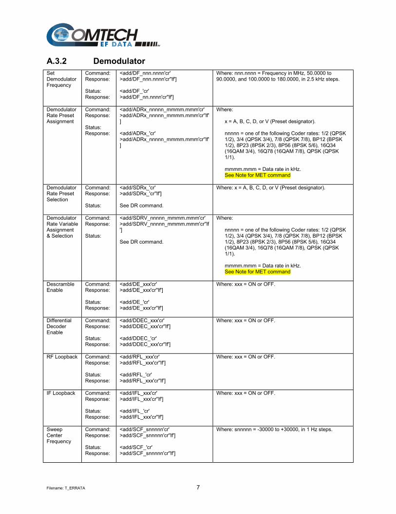
A.3.2 Demodulator Set Demodulator Frequency
Command: Response: Status: Response:
<add/DF_nnn.nnnn'cr' >add/DF_nnn.nnnn'cr''lf'] <add/DF_'cr' >add/DF_nn.nnnn'cr''lf']
Where: nnn.nnnn = Frequency in MHz, 50.0000 to 90.0000, and 100.0000 to 180.0000, in 2.5 kHz steps.
Demodulator Rate Preset Assignment
Command: Response: Status: Response:
<add/ADRx_nnnnn_mmmm.mmm'cr' >add/ADRx_nnnnn_mmmm.mmm'cr''lf'] <add/ADRx_'cr' >add/ADRx_nnnnn_mmmm.mmm'cr''lf']
Where:
x = A, B, C, D, or V (Preset designator). nnnnn = one of the following Coder rates: 1/2 (QPSK 1/2), 3/4 (QPSK 3/4), 7/8 (QPSK 7/8), BP12 (BPSK 1/2), 8P23 (8PSK 2/3), 8P56 (8PSK 5/6), 16Q34 (16QAM 3/4), 16Q78 (16QAM 7/8), QPSK (QPSK 1/1). mmmm.mmm = Data rate in kHz. See Note for MET command
Demodulator Rate Preset Selection
Command: Response: Status:
<add/SDRx_'cr' >add/SDRx_'cr''lf'] See DR command.
Where: x = A, B, C, D, or V (Preset designator).
Demodulator Rate Variable Assignment & Selection
Command: Response: Status:
<add/SDRV_nnnnn_mmmm.mmm'cr' >add/SDRV_nnnnn_mmmm.mmm'cr''lf'] See DR command.
Where:
nnnnn = one of the following Coder rates: 1/2 (QPSK 1/2), 3/4 (QPSK 3/4), 7/8 (QPSK 7/8), BP12 (BPSK 1/2), 8P23 (8PSK 2/3), 8P56 (8PSK 5/6), 16Q34 (16QAM 3/4), 16Q78 (16QAM 7/8), QPSK (QPSK 1/1). mmmm.mmm = Data rate in kHz. See Note for MET command
Descramble Enable
Command: Response: Status: Response:
<add/DE_xxx'cr' >add/DE_xxx'cr''lf'] <add/DE_'cr' >add/DE_xxx'cr''lf']
Where: xxx = ON or OFF.
Differential Decoder Enable
Command: Response: Status: Response:
<add/DDEC_xxx'cr' >add/DDEC_xxx'cr''lf'] <add/DDEC_'cr' >add/DDEC_xxx'cr''lf']
Where: xxx = ON or OFF.
RF Loopback Command: Response: Status: Response:
<add/RFL_xxx'cr' >add/RFL_xxx'cr''lf'] <add/RFL_'cr' >add/RFL_xxx'cr''lf']
Where: xxx = ON or OFF.
IF Loopback Command: Response: Status: Response:
<add/IFL_xxx'cr' >add/IFL_xxx'cr''lf'] <add/IFL_'cr' >add/IFL_xxx'cr''lf']
Where: xxx = ON or OFF.
Sweep Center Frequency
Command: Response: Status: Response:
<add/SCF_snnnnn'cr' >add/SCF_snnnnn'cr''lf'] <add/SCF_'cr' >add/SCF_snnnnn'cr''lf']
Where: snnnnn = -30000 to +30000, in 1 Hz steps.

Filename: T_ERRATA 8
Sweep Width Range
Command: Response: Status: Response:
<add/SWR_nnnnn'cr' >add/SWR_nnnnn'cr''lf'] <add/SWR_'cr' >add/SWR_nnnnn'cr''lf']
Where: nnnnn = 0 to 60000, in 1 Hz steps.
Sweep Reacquisition
Command: Response: Status: Response:
<add/SR_xxx'cr' >add/SR_xxx'cr''lf'] <add/SR_'cr' >add/SR_xxx'cr''lf']
Where: xxx = 0 to 999 (number of seconds).
Bit Error Rate Threshold
Command: Response: Status: Response:
<add/BERT_xxxx'cr' >add/BERT_xxxx'cr''lf'] <add/BERT_'cr' >add/BERT_xxxx'cr''lf']
Where: xxxx = NONE or 1E-n (where n = 3, 4, 5, 6, 7, or 8 [exponent of threshold]).
Demodulator Type
Command: Response: Status: Response:
<add/DT_xxxx'cr' >add/DT_xxxx'cr''lf'] <add/DT_xxxx'cr' >add/DT_xxxx'cr''lf']
Where: xxxx = INTL (INTELSAT OPEN NETWORK), EFD (EFData CLOSED NETWORK), CSC (COMSTREAM CLOSED NETWORK), or FDC (FAIRCHILD CLOSED NETWORK). See Note for MET command
Demodulator Decoder Type
Command: Response: Status: Response:
<add/DDT_xxx'cr' >add/DDT_xxx'cr''lf'] <add/DDT_xxx'cr' >add/DDT_xxx'cr''lf']
Where: xxx = VIT (K-7 VITERBI ENCODER) or SEQ (SEQUENTIAL ENCODER). Note: The CSC mod/demod type is not compatible with the combination of a Sequential encoder or decoder type and a 3/4 code rate.
Demodulator Spectrum Rotation
Command: Response: Status: Response:
<add/DSR_xxxx'cr' >add/DSR_xxxx'cr''lf'] <add/DSR_'cr' >add/DSR_xxxx'cr''lf']
Where: xxxx = NRM (normal spectrum) or INV (inverted spectrum).
Reed-Solomon Decoder Enable
Command: Response: Status: Response:
<add/RSDE_xxx'cr’ >add/RSDE_xxx'cr'’lf'] <add/RSDE_'cr' >add/RSDE_xxx'cr’'lf']
Where: xxx = ON, OFF, or CORR_OFF.
RX 8PSK 2/3 IESS-310 Operation
Command: Response: Status: Response:
<add/R310_xxx'cr' >add/R310_xxx'cr''lf'] <add/R310_'cr' >add/R310_xxx'cr''lf']
Where: xxx = ON or OFF.

Filename: T_ERRATA 1
Errata F Comtech EF Data Documentation Update
Subject: Changes to Table 3-11 (IDR Defaults) Date: October 5, 2001 Document: SDM-8000 Satellite Data Modem Installation and Operation
Manual, Rev. 12, dated August 6, 1999 Part Number: MN/SDM8000.EFC Collating Instructions: Attach this page to page 3-19 Comments: The following changes provide updated information for Table 3-11.
Table 3-11. IDR Defaults
Modulator Defaults Demodulator Defaults Data Rate [A (QPSK 3/4)] Data Rate [A (QPSK 3/4)] TX Rate A [1640 kbit/s] RX Rate A [1640 kbit/s] TX Rate B [2144 kbit/s] RX Rate B [2144 kbit/s] TX Rate C [6408 kbit/s] RX Rate C [6408 kbit/s] TX Rate D [8544 kbit/s] RX Rate D [8544 kbit/s] TX Rate V [1640 kbit/s] RX Rate V [1640 kbit/s] IF Frequency [70 MHz] IF Frequency [70 MHz] IF Output [OFF] Demodulator Type [INTELSAT Open] Mod Power Offset [0 dB] V.35 Descrambler [ON] TX Power Level [-10 dBm] Differential Decoder [ON] V.35 Scrambler [ON] Decoder Type [Viterbi] Differential Encoder [ON] IF Loopback
Demod Spectrum [OFF] [Normal]
Modulator Type [INTELSAT Open Net] RF Loopback [OFF] Encoder Type [Viterbi] Sweep Center [0 Hz] Carrier Mode [Normal (OFF)] Sweep Range [60000 Hz] Mod Power Fixed [0 dB] Reacquisition [0 seconds] Mod Spectrum [Normal] BER Threshold [NONE]
Interface Defaults TX Clock Source [TX Terrestrial] Buffer Program [Bits] Buffer Clk Source [RX Satellite] Buffer Size [384] TX Clock Phase [Auto] T1 Framing Structure [G.704] RX Clock Phase [Normal] E1 Framing Structure [G.704] Ext-Ref Freq [1544 kHz] T2 Framing Structure [G.743] B-Band Loopback [OFF] E2 Framing Structure [G.742] Intrfc Loopback [OFF] Service Channel TX [-5 dBm] TX Coding Format [AMI] Service Channel RX [-5 dBm] RX Coding Format [AMI] Loop Timing [OFF] TX 2047 Pattern [OFF] TX Overhead Type [IDR] RX 2047 Pattern [OFF] RX Overhead Type [IDR] TX Data Fault [NONE] TX Data Phase [Normal] RX Data Fault [NONE] RX Data Phase [Normal] TX Terr Interface [G.703] IDR B/W Alarm Control [ON] RX Terr Interface [G.703]

Filename: T_ERRATA 1
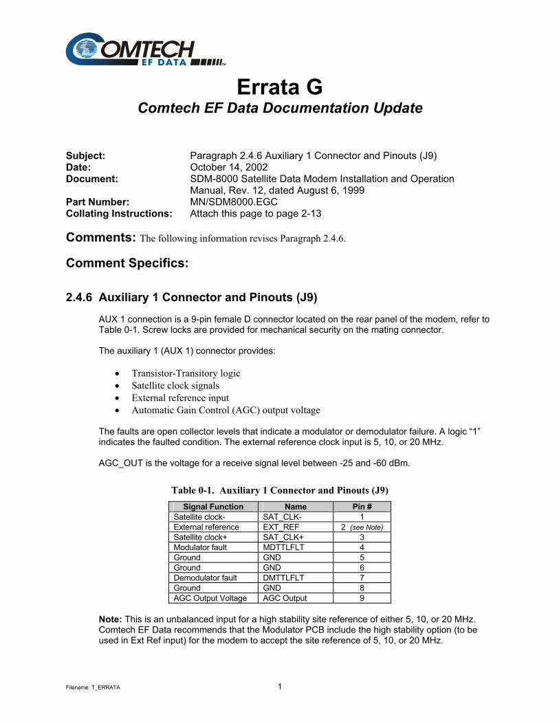
Errata G Comtech EF Data Documentation Update
Subject: Paragraph 2.4.6 Auxiliary 1 Connector and Pinouts (J9) Date: October 14, 2002 Document: SDM-8000 Satellite Data Modem Installation and Operation
Manual, Rev. 12, dated August 6, 1999 Part Number: MN/SDM8000.EGC Collating Instructions: Attach this page to page 2-13 Comments: The following information revises Paragraph 2.4.6.
Comment Specifics:
2.4.6 Auxiliary 1 Connector and Pinouts (J9) AUX 1 connection is a 9-pin female D connector located on the rear panel of the modem, refer to Table 0-1. Screw locks are provided for mechanical security on the mating connector. The auxiliary 1 (AUX 1) connector provides:
• Transistor-Transitory logic • Satellite clock signals • External reference input • Automatic Gain Control (AGC) output voltage
The faults are open collector levels that indicate a modulator or demodulator failure. A logic “1” indicates the faulted condition. The external reference clock input is 5, 10, or 20 MHz. AGC_OUT is the voltage for a receive signal level between -25 and -60 dBm.
Table 0-1. Auxiliary 1 Connector and Pinouts (J9) Signal Function Name Pin #
Satellite clock- SAT_CLK- 1 External reference EXT_REF 2 (see Note) Satellite clock+ SAT_CLK+ 3 Modulator fault MDTTLFLT 4 Ground GND 5 Ground GND 6 Demodulator fault DMTTLFLT 7 Ground GND 8 AGC Output Voltage AGC Output 9
Note: This is an unbalanced input for a high stability site reference of either 5, 10, or 20 MHz. Comtech EF Data recommends that the Modulator PCB include the high stability option (to be used in Ext Ref input) for the modem to accept the site reference of 5, 10, or 20 MHz.


Copyright © Comtech EF Data, 2000. All rights reserved. Printed in the USA. Comtech EF Data, 2114 West 7th Street, Tempe, Arizona 85281 USA, (480) 333-2200, FAX: (480) 333-2161.
SDM-8000 Satellite Modem
Installation and Operation Manual
Part Number MN/SDM8000.IOM Revision 12
August 6, 1999
Comtech EF Data is an ISO 9001 Registered Company.
ii Rev.12
Customer Support
Contact the Comtech EF Data Customer Support Department for: • Product support or training • Information on upgrading or returning a product • Reporting comments or suggestions concerning manuals A Customer Support representative may be reached at:
Comtech EF Data Attention: Customer Support Department 2114 West 7th Street Tempe, Arizona 85281 USA (480) 333-2200 (Main Comtech EF Data Number) (480) 333-4357 (Customer Support Desk) (480) 333-2161 FAX
or, E-Mail can be sent to the Customer Support Department at:
[email protected] Contact us via the web at www.comtechefdata.com.
1. To return a Comtech EF Data product (in-warranty and out-of-warranty) for repair or replacement:
2. Request a Return Material Authorization (RMA) number from the Comtech EF
Data Customer Support Department. 3. Be prepared to supply the Customer Support representative with the model
number, serial number, and a description of the problem. 4. To ensure that the product is not damaged during shipping, pack the product in
its original shipping carton/packaging. 5. Ship the product back to Comtech EF Data. (Shipping charges should be
prepaid.) For more information regarding the warranty policies, see Warranty Policy, p. xix.

Rev.12 iii
Table of Contents
Customer Support ...................................................................................................................................................... ii
Overview of Changes to Previous Edition ..............................................................................................................xiv
About this Manual ....................................................................................................................................................xiv
EMC Compliance ................................................................................................................................................... xvii
Reporting Comments or Suggestions Concerning this Manual......................................................................... xviii
Warranty Policy........................................................................................................................................................xix
CHAPTER 1. INTRODUCTION..........................................................................................................1–1
1.1 Overview......................................................................................................................................................1–2 1.1.1 Modem Types ..........................................................................................................................................1–2 1.1.2 Modem Construction................................................................................................................................1–3
1.2 Options ........................................................................................................................................................1–5 1.2.1 Sequential Decoder ..................................................................................................................................1–5 1.2.2 D&I with ASYNC Overhead ...................................................................................................................1–6 1.2.3 Reed-Solomon..........................................................................................................................................1–6 1.2.4 8PSK ........................................................................................................................................................1–6 1.2.5 16QAM ....................................................................................................................................................1–6 1.2.6 Interface Relay Board ..............................................................................................................................1–7
1.3 Breakout Panels ..........................................................................................................................................1–8
1.4 Modem Assemblies ...................................................................................................................................1–10
1.5 Specifications ............................................................................................................................................1–11
1.6 Typical Spectral Occupancy ....................................................................................................................1–12
1.7 Dimensional Envelope ..............................................................................................................................1–13

Preface SDM-8000 Satellite Modem
iv Rev.12
CHAPTER 2. INSTALLATION...........................................................................................................2–1
2.1 Unpacking ...................................................................................................................................................2–1
2.2 System Options ...........................................................................................................................................2–2
2.3 Installation ..................................................................................................................................................2–3
2.4 External Connections .................................................................................................................................2–5 2.4.1 RF Output Connector (CP1).....................................................................................................................2–6 2.4.2 RF Input Connector (CP2) .......................................................................................................................2–6 2.4.3 Remote Connector and Pinouts (J6).........................................................................................................2–6 2.4.4 Fault Connector and Pinouts (J7) .............................................................................................................2–7 2.4.5 DATA I/O Interface Connector (J8) ........................................................................................................2–7
2.4.5.1 IDR Configuration Connector Pinouts (J8) .....................................................................................2–8 2.4.5.1.1 Cable (CA/5876) Pin Assignments ............................................................................................2–9
2.4.5.2 IBS Interface Connector Pinouts (J8)............................................................................................2–10 2.4.5.3 IDR/D&I Interface Connector Pinouts (J8)...................................................................................2–11 2.4.5.4 EIA-422 Data with IDR Overhead ................................................................................................2–12
2.4.6 Auxiliary 1 Connector and Pinouts (J9) .................................................................................................2–13 2.4.7 Alarms Connector and Pinouts (J10)......................................................................................................2–14 2.4.8 AC Power Connector .............................................................................................................................2–14 2.4.9 Ground Connector (GND)......................................................................................................................2–14
CHAPTER 3. CONFIGURATION.......................................................................................................3–1
3.1 Display/M&C Configuration .....................................................................................................................3–1 3.1.1 Remote Baud Rate....................................................................................................................................3–3 3.1.2 Remote Address .......................................................................................................................................3–3
3.2 Modulator Configuration...........................................................................................................................3–4
3.3 Demodulator Configuration ......................................................................................................................3–6
3.4 Interface Configuration .............................................................................................................................3–8
3.5 Software Configuration............................................................................................................................3–12 3.5.1 Modem Types ........................................................................................................................................3–12
3.5.1.1 IDR, IBS, and D&I Operation.......................................................................................................3–13 3.5.1.2 Custom Operation..........................................................................................................................3–14
3.5.2 Remote Interface Specification ..............................................................................................................3–14 3.5.3 Revision Emulation................................................................................................................................3–14 3.5.4 Modem Emulation..................................................................................................................................3–16
3.6 Modem Defaults........................................................................................................................................3–18 3.6.1 IDR.........................................................................................................................................................3–19 3.6.2 IBS .........................................................................................................................................................3–20 3.6.3 Drop & Insert .........................................................................................................................................3–21 3.6.4 Custom ...................................................................................................................................................3–22 3.6.5 Type X (1 through 5)..............................................................................................................................3–23 3.6.6 System....................................................................................................................................................3–23
CHAPTER 4. OPERATION................................................................................................................4–1
SDM-8000 Satellite Modem Preface
Rev.12 v
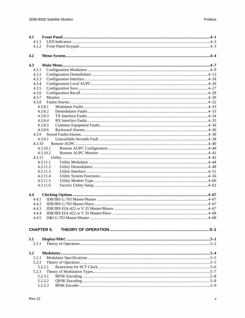
4.1 Front Panel..................................................................................................................................................4–1 4.1.1 LED Indicators .........................................................................................................................................4–2 4.1.2 Front Panel Keypad..................................................................................................................................4–3
4.2 Menu System...............................................................................................................................................4–4
4.3 Main Menu..................................................................................................................................................4–7 4.3.1 Configuration Modulator .........................................................................................................................4–9 4.3.2 Configuration Demodulator ...................................................................................................................4–13 4.3.3 Configuration Interface ..........................................................................................................................4–18 4.3.4 Configuration Local AUPC....................................................................................................................4–26 4.3.5 Configuration Save.................................................................................................................................4–27 4.3.6 Configuration Recall ..............................................................................................................................4–28 4.3.7 Monitor ..................................................................................................................................................4–30 4.3.8 Faults/Alarms .........................................................................................................................................4–32
4.3.8.1 Modulator Faults ...........................................................................................................................4–33 4.3.8.2 Demodulator Faults .......................................................................................................................4–33 4.3.8.3 TX Interface Faults........................................................................................................................4–34 4.3.8.4 RX Interface Faults .......................................................................................................................4–35 4.3.8.5 Common Equipment Faults...........................................................................................................4–36 4.3.8.6 Backward Alarms ..........................................................................................................................4–36
4.3.9 Stored Faults/Alarms..............................................................................................................................4–38 4.3.9.1 Unavailable Seconds Fault ............................................................................................................4–38
4.3.10 Remote AUPC ...................................................................................................................................4–40 4.3.10.1 Remote AUPC Configuration ...................................................................................................4–40 4.3.10.2 Remote AUPC Monitor ............................................................................................................4–41
4.3.11 Utility.................................................................................................................................................4–42 4.3.11.1 Utility Modulator ......................................................................................................................4–44 4.3.11.2 Utility Demodulator ..................................................................................................................4–48 4.3.11.3 Utility Interface .........................................................................................................................4–51 4.3.11.4 Utility System Functions...........................................................................................................4–56 4.3.11.5 Utility Modem Type..................................................................................................................4–60 4.3.11.6 Factory Utility Setup.................................................................................................................4–62
4.4 Clocking Options ......................................................................................................................................4–67 4.4.1 IDR/IBS G.703 Master/Master ..............................................................................................................4–67 4.4.2 IDR/IBS G.703 Master/Slave.................................................................................................................4–67 4.4.3 IDR/IBS EIA-422 or V.35 Master/Master .............................................................................................4–67 4.4.4 IDR/IBS EIA-422 or V.35 Master/Slave ...............................................................................................4–68 4.4.5 D&I G.703 Master/Master .....................................................................................................................4–68
CHAPTER 5. THEORY OF OPERATION..........................................................................................5–1
5.1 Display/M&C ..............................................................................................................................................5–1 5.1.1 Theory of Operation.................................................................................................................................5–2
5.2 Modulator....................................................................................................................................................5–4 5.2.1 Modulator Specifications .........................................................................................................................5–5 5.2.2 Theory of Operation.................................................................................................................................5–5
5.2.2.1 Restriction for SCT Clock ...............................................................................................................5–6 5.2.3 Theory of Modulation Types....................................................................................................................5–7
5.2.3.1 BPSK Encoding...............................................................................................................................5–8 5.2.3.2 QPSK Encoding ..............................................................................................................................5–8 5.2.3.3 8PSK Encoder .................................................................................................................................5–9
Preface SDM-8000 Satellite Modem
vi Rev.12
5.2.3.4 16QAM Encoding ...........................................................................................................................5–9
5.3 Demodulator .............................................................................................................................................5–11 5.3.1 Demodulator Specifications ...................................................................................................................5–12 5.3.2 Theory of Operation...............................................................................................................................5–12
5.4 Viterbi Decoder.........................................................................................................................................5–14 5.4.1 Specifications .........................................................................................................................................5–14 5.4.2 Theory of Operation...............................................................................................................................5–15
5.5 Interface ....................................................................................................................................................5–16 5.5.1 Interface Specifications..........................................................................................................................5–18 5.5.2 Theory of Operation...............................................................................................................................5–18
5.5.2.1 Closed Network.............................................................................................................................5–18 5.5.2.2 Open Network ...............................................................................................................................5–19 5.5.2.3 IDR................................................................................................................................................5–19 5.5.2.4 64 kbit/s Service Channel Option..................................................................................................5–20 5.5.2.5 8 kbit/s Synchronous Data Channel...............................................................................................5–21 5.5.2.6 IBS.................................................................................................................................................5–22
5.6 Backward Alarm Theory and Connections............................................................................................5–23
CHAPTER 6. MAINTENANCE...........................................................................................................6–1
6.1 System Checkout ........................................................................................................................................6–1 6.1.1 Interface Checkout ...................................................................................................................................6–2 6.1.2 Modulator Checkout.................................................................................................................................6–3 6.1.3 Demodulator Checkout ............................................................................................................................6–6 6.1.4 PCB Test Points .......................................................................................................................................6–8
6.1.4.1 Interface PCB Test Points ...............................................................................................................6–8 6.1.4.2 Modulator PCB Test Points.............................................................................................................6–9 6.1.4.3 Demodulator PCB Test Points.......................................................................................................6–10
6.2 Fault Isolation ...........................................................................................................................................6–11 6.2.1 System Faults/Alarms ............................................................................................................................6–11 6.2.2 Fault/Alarm Display and Description.....................................................................................................6–15 6.2.3 Fault/Alarm Analysis .............................................................................................................................6–15
6.2.3.1 Modulator Faults ...........................................................................................................................6–16 6.2.3.2 Demodulator Faults .......................................................................................................................6–18 6.2.3.3 Transmit Interface Faults...............................................................................................................6–20 6.2.3.4 Receive Interface Faults ................................................................................................................6–21 6.2.3.5 Common Equipment Faults...........................................................................................................6–23 6.2.3.6 Backward Alarms ..........................................................................................................................6–24
6.3 Module Replacement................................................................................................................................6–24
APPENDIX A. REMOTE CONTROL OPERATION............................................................................ A–1
A.1 General .......................................................................................................................................................A–1
A.2 Message Structure .....................................................................................................................................A–2 A.2.1 Start Character ....................................................................................................................................A–2 A.2.2 Device Address...................................................................................................................................A–2

SDM-8000 Satellite Modem Preface
Rev.12 vii
A.2.3 Command/Response ...........................................................................................................................A–3 A.2.4 End Character .....................................................................................................................................A–3
A.3 Configuration Commands/Responses......................................................................................................A–4 A.3.1 Modulator ...........................................................................................................................................A–4 A.3.2 Demodulator .......................................................................................................................................A–6 A.3.3 Interface Configuration Commands....................................................................................................A–8 A.3.4 System ..............................................................................................................................................A–14 A.3.5 AUPC................................................................................................................................................A–15
A.4 Status Commands/Responses .................................................................................................................A–17 A.4.1 Configuration....................................................................................................................................A–17 A.4.2 Error Performance ............................................................................................................................A–24
A.5 Stored Faults ............................................................................................................................................A–27
APPENDIX B. OPTIONS .................................................................................................................... B–1
B.1 Sequential Decoder....................................................................................................................................B–1 B.1.1 Specifications......................................................................................................................................B–2 B.1.2 Theory of Operation ...........................................................................................................................B–3 B.1.3 Unpacking...........................................................................................................................................B–4 B.1.4 Installation ..........................................................................................................................................B–5
B.2 D&I with Asynchronous Overhead..........................................................................................................B–7 B.2.1 Specifications......................................................................................................................................B–7 B.2.2 Asynchronous Overhead Operation....................................................................................................B–7 B.2.3 Theory of Operation ...........................................................................................................................B–7
B.2.3.1 Data Interface .................................................................................................................................B–9 B.2.3.2 Transmit Multiplexer......................................................................................................................B–9 B.2.3.3 Receive Demultiplexer .................................................................................................................B–10 B.2.3.4 Asynchronous Overhead ..............................................................................................................B–10 B.2.3.5 Plesiochronous Buffer ..................................................................................................................B–10 B.2.3.6 Engineering Service Channel (ESC) ............................................................................................B–11 B.2.3.7 Automatic Uplink Power Control (AUPC)...................................................................................B–11 B.2.3.8 Modem to Modem Channel for Remote.......................................................................................B–12 B.2.3.9 Backward Alarm...........................................................................................................................B–12
B.2.4 Unpacking.........................................................................................................................................B–13 B.2.5 Installation ........................................................................................................................................B–13
B.3 Reed-Solomon Codec...............................................................................................................................B–15 B.3.1 Specifications....................................................................................................................................B–15 B.3.2 Theory of Operation .........................................................................................................................B–15
B.3.2.1 Reed-Solomon Encoder................................................................................................................B–16 B.3.2.2 Reed-Solomon Decoder................................................................................................................B–18
B.3.3 Unpacking.........................................................................................................................................B–20 B.3.4 Installation ........................................................................................................................................B–20
B.4 Interface Relay Board .............................................................................................................................B–22 B.4.1 Theory of Operation .........................................................................................................................B–22 B.4.2 Unpacking.........................................................................................................................................B–23 B.4.3 Installation ........................................................................................................................................B–23 B.4.4 Operation ..........................................................................................................................................B–24
B.4.4.1 Operational Check........................................................................................................................B–24
Preface SDM-8000 Satellite Modem
viii Rev.12
B.4.4.2 Interface Option Menu .................................................................................................................B–26 B.4.4.3 Interface Build Menu....................................................................................................................B–26 B.4.4.4 G.703 Menu..................................................................................................................................B–26
B.5 Digital Video Broadcast (DVB) ..............................................................................................................B–27 B.5.1 Option Requirements ........................................................................................................................B–28
B.5.1.1 DVB Option .................................................................................................................................B–28 B.5.1.2 Display/M&C ...............................................................................................................................B–29
B.5.2 Baseband Interface............................................................................................................................B–30 B.5.2.1 Terrestrial 188 Byte Frame Format (MPEG-2 Transport Data Packet)........................................B–31
B.5.2.1.1 Transmit Terrestrial 188 Byte Frame Format.........................................................................B–31 B.5.2.1.2 Receive Terrestrial 188 Byte Frame Format ..........................................................................B–31
B.5.2.2 Terrestrial No Framing Format ....................................................................................................B–32 B.5.2.2.1 Transmit Terrestrial No Framing Format ...............................................................................B–32 B.5.2.2.2 Receive Terrestrial No Framing Format.................................................................................B–32
B.5.2.3 Terrestrial 204 Byte Framing Format...........................................................................................B–33 B.5.2.3.1 Transmit Terrestrial 204 Byte Framing Format .....................................................................B–33 B.5.2.3.2 Receive Terrestrial 204 Byte Framing Format .......................................................................B–33
B.5.3 Sync Decoder (Correlator)................................................................................................................B–34 B.5.3.1 Transmit/Receive Contingencies..................................................................................................B–34 B.5.3.2 Transport Error Indicator..............................................................................................................B–34
B.5.4 Sync 1 Inversion and Scrambler/Descrambler..................................................................................B–35 B.5.4.1 DVB (De)Scrambler.....................................................................................................................B–36
B.5.5 Reed-Solomon Coder/Decoder .......................................................................................................B–37 B.5.6 Depth 12 Interleaver/De-interleaver .................................................................................................B–38 B.5.7 Inner Coder/Decoder.........................................................................................................................B–40
B.5.7.1 Punctured Operation.....................................................................................................................B–40 B.5.7.2 Signal Space Mapping..................................................................................................................B–41
B.5.8 Nyquist Filters ..................................................................................................................................B–42 B.5.9 DVB with Reed-Solomon BER (QPSK) ..........................................................................................B–43
B.6 Asymmetrical Loop Timing....................................................................................................................B–45 B.6.1 Description........................................................................................................................................B–45 B.6.2 Optional Clocking Options ...............................................................................................................B–45 B.6.3 Internal SCT Clock ...........................................................................................................................B–46
APPENDIX C. SPECIFICATIONS ...................................................................................................... C–1
C.1 Specifications .............................................................................................................................................C–1 C.1.1 General Specification..........................................................................................................................C–1 C.1.2 BER Performance ...............................................................................................................................C–5
C.1.2.1 Performance with Noise, Viterbi Decoder, IBS, and D&I Mode ...................................................C–6 C.1.2.2 Performance with Noise, Sequential Decoder, BPSK, QPSK, and 56 kbit/s .................................C–8 C.1.2.3 Performance with Noise, Sequential Decoder, BPSK, QPSK, and 1544 kbit/s............................C–10 C.1.2.4 Performance with Noise and Reed-Solomon................................................................................C–12 C.1.2.5 Performance with Noise, Viterbi Decoder, and 8PSK 2/3 ...........................................................C–14 C.1.2.6 Performance with Noise, Viterbi Decoder, and 8PSK 5/6 ...........................................................C–16 C.1.2.7 Performance with Noise, Viterbi Decoder, and 16QAM..............................................................C–18
C.1.3 Acquisition Time ..............................................................................................................................C–20 C.1.4 Receive IF Test Modes .....................................................................................................................C–20 C.1.5 Receive IF Carrier Acquisition Range..............................................................................................C–20 C.1.6 AGC Output......................................................................................................................................C–20
SDM-8000 Satellite Modem Preface
Rev.12 ix
C.2 Modulator Specification..........................................................................................................................C–21
C.3 Demodulator Specifications ....................................................................................................................C–22
C.4 Interface-Related Specifications.............................................................................................................C–23 C.4.1 Digital Interface Specifications.........................................................................................................C–23
C.4.1.1 G.703 Specifications ....................................................................................................................C–24 C.4.1.2 MIL-STD-188/449 Specifications................................................................................................C–24 C.4.1.3 V.35 Specifications ......................................................................................................................C–25 C.4.1.4 IDR Interface Specifications ........................................................................................................C–25 C.4.1.5 IBS Interface Specification...........................................................................................................C–26 C.4.1.6 D&I Interface Specifications........................................................................................................C–27 C.4.1.7 Asynchronous Interface Specifications ........................................................................................C–29 C.4.1.8 Reed-Solomon Specifications (Optional) .....................................................................................C–30
C.5 Interface General.....................................................................................................................................C–30 C.5.1 Transmit Clock Source .....................................................................................................................C–30 C.5.2 Buffer Clock .....................................................................................................................................C–31 C.5.3 Switch Faults ....................................................................................................................................C–31 C.5.4 Data Phase ........................................................................................................................................C–31
C.6 System-Related Specifications ................................................................................................................C–32 C.6.1 Monitored Signals.............................................................................................................................C–32
GLOSSARY ............................................................................................................................................. g-1
INDEX ............................................................................................................................................. i-1

Preface SDM-8000 Satellite Modem
x Rev.12
Figures Figure 1-1. SDM-8000.....................................................................................................................................1–1 Figure 1-2. Modulator Construction ................................................................................................................1–3 Figure 1-3. Block Diagram ..............................................................................................................................1–4 Figure 1-4. SDM-8000 Typical Spectral Occupancy.....................................................................................1–12 Figure 1-5. Dimensional Envelope ................................................................................................................1–13 Figure 2-1. Typical Rack Installation ..............................................................................................................2–4 Figure 2-2. SDM-8000 Rear Panel View.........................................................................................................2–5 Figure 3-1. Display/M&C PCB .......................................................................................................................3–2 Figure 3-2. Modulator PCB .............................................................................................................................3–5 Figure 3-3. Demodulator PCB .........................................................................................................................3–7 Figure 3-4. Interface PCB..............................................................................................................................3–10 Figure 4-1. Front Panel View...........................................................................................................................4–1 Figure 4-2. Front Panel Keypad.......................................................................................................................4–3 Figure 4-3. Main Menu....................................................................................................................................4–7 Figure 4-4. Configuration Modulator Menu ....................................................................................................4–8 Figure 4-5. Configuration Demodulator Menu ..............................................................................................4–12 Figure 4-6. Configuration Interface Menu .....................................................................................................4–16 Figure 4-7. Configuration Local AUPC Menu .............................................................................................4–25 Figure 4-8. Configuration Save Menu ..........................................................................................................4–27 Figure 4-9. Configuration Recall Menu.........................................................................................................4–28 Figure 4-10. Monitor Menu ...........................................................................................................................4–29 Figure 4-11. Faults/Alarms Menu..................................................................................................................4–31 Figure 4-12. Stored Faults/Alarms Menu.......................................................................................................4–37 Figure 4-13. Remote AUPC Configuration Menu .........................................................................................4–39 Figure 4-14. Remote AUPC Monitor Menu ..................................................................................................4–41 Figure 4-15. Utility Modulator Menu ............................................................................................................4–43 Figure 4-16. Utility Demodulator Menu ........................................................................................................4–47 Figure 4-17. Utility Interface Menu...............................................................................................................4–49 Figure 4-18. Utility System Menu .................................................................................................................4–55 Figure 4-19. Utility Modem Type Menu........................................................................................................4–59 Figure 4-20. Utility Factory Setup Menu.......................................................................................................4–62 Figure 4-21. RF Loopback.............................................................................................................................4–63 Figure 4-22. IF Loopback .............................................................................................................................4–64 Figure 4-23. Baseband Loopback (without D&I) ..........................................................................................4–64 Figure 4-24. Baseband Loopback (with D&I) ...............................................................................................4–65 Figure 4-25. Interface Loopback....................................................................................................................4–66 Figure 4-26. IDR/IBS G.703 Master/Master Clocking Diagram ...................................................................4–69 Figure 4-27. IDR/IBS G.703 Master/Slave Clocking Diagram .....................................................................4–70 Figure 4-28. IDR/IBS EIA-422/V.35 Master/Master Clocking Diagram ......................................................4–71 Figure 4-29. IDR/IBS EIA-422/V.35 Master/Slave Clocking Diagram ........................................................4–72 Figure 4-30. D&I G.703 Master/Master Clocking Diagram..........................................................................4–73 Figure 5-1. Display/M&C Block Diagram.......................................................................................................5–2 Figure 5-2. Modulator Block Diagram ............................................................................................................5–4 Figure 5-3. Demodulator Block Diagram ......................................................................................................5–11 Figure 5-4. Viterbi Decoder Block Diagram..................................................................................................5–14 Figure 5-5. Interface Block Diagram .............................................................................................................5–16 Figure 5-6. 8/64 kHz Clock ...........................................................................................................................5–20 Figure 6-1. Fault Isolation Test Setup..............................................................................................................6–2 Figure 6-2. Typical Output Spectrum (with Noise) .........................................................................................6–5 Figure 6-3. Typical Output Spectrum ..............................................................................................................6–5
SDM-8000 Satellite Modem Preface
Rev.12 xi
Figure 6-4. Typical Eye Constellations............................................................................................................6–7 Figure 6-5. Interface PCB Test Points .............................................................................................................6–9 Figure 6-6. Modulator PCB Test Points...........................................................................................................6–9 Figure 6-7. Demodulator PCB Test Points ....................................................................................................6–10 Figure B-1. Sequential Decoder Block Diagram .............................................................................................B–2 Figure B-2. Sequential Decoder Installation....................................................................................................B–6 Figure B-3. D&I with Asynchronous Overhead Block Diagram.....................................................................B–8 Figure B-4. D&I Multiplexer Installation ......................................................................................................B–14 Figure B-5. Reed-Solomon Codec Block Diagram........................................................................................B–16 Figure B-6. Reed-Solomon Encoder Section Block Diagram........................................................................B–16 Figure B-7. Reed-Solomon Code Page Format..............................................................................................B–18 Figure B-8. Reed-Solomon Decoder Section Block Diagram .......................................................................B–19 Figure B-9. Reed-Solomon Codec Installation ..............................................................................................B–21 Figure B-10. Interface Relay Board...............................................................................................................B–22 Figure B-11. Interface Relay Board Installation ............................................................................................B–25 Figure B-12. Block Diagram of SDM-8000 Configured for DVB Operation...............................................B–27 Figure B-13. Configuration Interface Menu .................................................................................................B–29 Figure B-14. Baseband Terrestrial Framing Block Diagram ........................................................................B–30 Figure B-15. MPEG-2 Transport Packet.......................................................................................................B–31 Figure B-16. (No Framing) DVB Baseband Packet......................................................................................B–32 Figure B-17. 204-byte Mode Baseband Packet.............................................................................................B–33 Figure B-18. Scrambler/Descrambler ...........................................................................................................B–35 Figure B-19. DVB Scrambler Sequence .......................................................................................................B–36 Figure B-20. Reed-Solomon RS(204,188,8) Error-Protected Packet............................................................B–37 Figure B-21. Interleaver/De-interleaver........................................................................................................B–38 Figure B-22. Interleaved Frame Structure ....................................................................................................B–39 Figure B-23. DVB Puncturing ......................................................................................................................B–40 Figure B-24. QPSK Constellation.................................................................................................................B–41 Figure B-25. QPSK (1/2, 3/4, 7/8) with Reed-Solomon (DVB) ...................................................................B–44 Figure B-26. Internal SCT Clock..................................................................................................................B–46 Figure C-1. Viterbi BER , IBS, and D&I Mode Performance Curves ............................................................C–7 Figure C-2. Sequential Decoder 56 kbit/s BER Performance Curves.............................................................C–9 Figure C-3. Sequential Decoder, 1544 kbit/s BER Performance Curves......................................................C–11 Figure C-4. Noise and Reed-Solomon ..........................................................................................................C–13 Figure C-5. Noise, Viterbi Decoder, and 8PSK 2/3 BER Performance Curves............................................C–15 Figure C-6. Viterbi Decoder, 8PSK 5/6 BER Performance Curves..............................................................C–17 Figure C-7. Viterbi Decoder and 16QAM ....................................................................................................C–19
Preface SDM-8000 Satellite Modem
xii Rev.12
Tables Table 1-1. Module Types.................................................................................................................................1–5 Table 1-2. Breakout Panel Configurations.......................................................................................................1–8 Table 1-3. Modem Assemblies ......................................................................................................................1–10 Table 2-1. Modem Rear Panel Connectors ......................................................................................................2–5 Table 2-2. Remote Connector and Pinouts (J6) ...............................................................................................2–6 Table 2-3. Fault Connector and Pinouts (J7) ...................................................................................................2–7 Table 2-4. IDR Configuration Connector Pinouts (J8) ....................................................................................2–8 Table 2-5. IBS Interface Connector Pinouts (J8) ...........................................................................................2–10 Table 2-6. IDR/D&I Interface Connector Pinouts (J8) ..................................................................................2–11 Table 2-7. Auxiliary 1 Connector and Pinouts (J9) .......................................................................................2–13 Table 2-8. Alarms Connector and Pinouts (J10) ............................................................................................2–14 Table 3-1. Display/M&C PCB Jumper Settings ..............................................................................................3–1 Table 3-2. Modular PCB Jumper Settings .......................................................................................................3–4 Table 3-3. Demodulator PCB Jumper Settings ................................................................................................3–6 Table 3-4. Interface Configuration Jumper Settings ........................................................................................3–8 Table 3-5. Type X Interface Configuration Jumper Settings .........................................................................3–11 Table 3-6. Description of Interface Jumpers..................................................................................................3–11 Table 3-7. Modem Types...............................................................................................................................3–12 Table 3-8. SDM-8000 Revision Emulation ...................................................................................................3–15 Table 3-9. Modem Emulation Types .............................................................................................................3–16 Table 3-10. Modem Emulation ......................................................................................................................3–17 Table 3-11. IDR Defaults...............................................................................................................................3–19 Table 3-12. IBS Defaults ...............................................................................................................................3–20 Table 3-13. D&I Defaults ..............................................................................................................................3–21 Table 3-14. Custom Defaults .........................................................................................................................3–22 Table 3-15. Type X (1 Through 5) Defaults ..................................................................................................3–23 Table 3-16. System Defaults..........................................................................................................................3–23 Table 4-1. Interface Jumper Settings .............................................................................................................4–54 Table 5-1. Viterbi Specification.....................................................................................................................5–14 Table 6-1. Conversion to S/N and Eb/N0 Chart ..............................................................................................6–4 Table 6-2. Interface PCB Test Points...............................................................................................................6–8 Table 6-3. Modulator PCB Test Points ............................................................................................................6–9 Table 6-4. Demodulator PCB Test Points......................................................................................................6–10 Table 6-5. SDM-8000 Fault Tree...................................................................................................................6–12 Table 6-6. Modulator Faults ..........................................................................................................................6–16 Table 6-7. Demodulator Faults ......................................................................................................................6–18 Table 6-8. Transmit Interface Faults..............................................................................................................6–20 Table 6-9. Receive Interface Faults ...............................................................................................................6–21 Table 6-10. Common Equipment Faults ........................................................................................................6–23 Table 6-11. Backward Alarm Faults ..............................................................................................................6–24 Table B-1. Sequential Decoder Specification ..................................................................................................B–2 Table B-2. Modem Compatibility Requirements..........................................................................................B–28 Table B-3. Rate Exchange Ratios for DVB Puncturing................................................................................B–41 Table B-4. Reed-Solomon BER Data ...........................................................................................................B–43 Table C-1. General Specifications ..................................................................................................................C–1 Table C-2. General Specifications (Continued) ..............................................................................................C–2 Table C-3. General Specifications (Continued) ..............................................................................................C–3 Table C-4. General Specifications (Continued) ..............................................................................................C–4 Table C-5. BER Performance .........................................................................................................................C–5 Table C-6. Viterbi Decoder BER Data ...........................................................................................................C–6 Table C-7. Sequential Decoder 56 kbit/s ........................................................................................................C–8
SDM-8000 Satellite Modem Preface
Rev.12 xiii
Table C-8. Sequential Decoder, 1544 kbit/s .................................................................................................C–10 Table C-9. Noise and Reed-Solomon ...........................................................................................................C–12 Table C-10. Viterbi Decoder and 8PSK 2/3..................................................................................................C–14 Table C-11. Viterbi Decoder and 8PSK 5/6 BER Data ................................................................................C–16 Table C-12. Viterbi Decoder and 16QAM....................................................................................................C–18 Table C-13. Modulator Specification............................................................................................................C–21 Table C-14. Demodulator Specification .......................................................................................................C–22 Table C-15. Digital Interface Specification ..................................................................................................C–23 Table C-16. G.703 Specifications .................................................................................................................C–24 Table C-17. MIL-STD-188/449 Specifications ............................................................................................C–24 Table C-18. V.35 Specifications ...................................................................................................................C–25 Table C-19. IDR Interface Specifications.....................................................................................................C–25 Table C-20. IBS Interface Specifications......................................................................................................C–26 Table C-21. D&I Interface Specifications ....................................................................................................C–27 Table C-22. Asynchronous Interface Specifications.....................................................................................C–29 Table C-23. Reed-Solomon Specifications ...................................................................................................C–30
Preface SDM-8000 Satellite Modem
xiv Rev.12
Overview of Changes to Previous Edition
The following changes were made for Rev 12:
• Added Note explaining EF Data is now Adaptive Broadband • Updated EMC Compliance statement. • 1-2, Deleted reference to DVB option. • 1-7, Deleted paragraph 1.27 Digital Video Broadcast (DVB) • 1-10, Added PN/5039-x PCB part numbers to Table 1-3. • 1-11, Relocated specification to Appendix C. • 1-13, Relocated dimensional envelope to Chapter 1 from Chapter 2. • 2-3, Added reference to AS/5039-x as alternate parts. • 2-4, Added typical rack installation figure. • 2-10 Revised Data Set Ready in Table 2-5. • 3-15, added Functional # 20 and 21, SW VER: 19.1.1 and 20.1.1 to Table 3-8. • Chapter 4, Revised menus to reflect Software Ver: 20.1.1. • Chapter 5, Relocation of specification data to Appendix C. • 5-6, Added Restriction for SCT Clock header. • Appendix A, Updated remote control specification to FW-2448-1AD • Appendix C. Added appendix to reflect unit specification. • Revised Index.
About this Manual
This manual provides installation and operation information for the Comtech EF Data SDM-8000 satellite modem. This is a technical document intended for earth station engineers, technicians, and operators responsible for the operation and maintenance of the SDM-8000.
Related Documents
The following documents are referenced in this manual:
• American Telephone and Telegraph (AT&T) 43802
• CCITT G.703, G.704, G.721, G.732, G.733, G.823, G.824
• Department of Defense (DOD) MIL-STD-188-114A, “Electrical Characteristics of Digital Interface Circuits”
• Comtech EF Data Specification SP/2300
• Comtech EF Data’s UB-300 Universal Breakout Panel Installation and
Operation Manual

SDM-8000 Satellite Modem Preface
Rev.12 xv
• Comtech EF Data’s IDR Breakout Panel Installation and Operation Manual
• Comtech EF Data’s IBS Breakout Panel Installation and Operation Manual
• Comtech EF Data’s IB-8004 Breakout Panel Installation and Operation Manual
• Comtech EF Data’s IB-8005 Breakout Panel Installation and Operation Manual
• Comtech EF Data’s D&I Breakout Panel Installation and Operation Manual
• Comtech EF Data’s ASYNC Breakout Panel Installation and Operation Manual
Conventions and References
Cautions and Warnings
CAUTION
CAUTION indicates a hazardous situation that, if not avoided, may result in minor or moderate injury. CAUTION may also be used to indicate other unsafe practices or risks of property damage.
WARNING
WARNING indicates a potentially hazardous situation that, if not avoided, could result in death or serious injury.
Preface SDM-8000 Satellite Modem
xvi Rev.12
Metric Conversion
Metric conversion information is located on the inside back cover of this manual. This information is provided to assist the operator in cross-referencing English to Metric conversions.
Recommended Standard Designations
Recommended Standard (RS) Designations have been superseded by the new designation of the Electronic Industries Association (EIA). References to the old designations are shown only when depicting actual text displayed on the screen of the unit (RS-232, RS-485, etc.). All other references in the manual will be shown with the EIA designations (EIA-232, EIA-485, etc.) only.
Military Standards
References to “MIL-STD-188” apply to the 114A series (i.e., MIL-STD-188-114A), which provides electrical and functional characteristics of the unbalanced and balanced voltage digital interface circuits applicable to both long haul and tactical communications. Specifically, these references apply to the MIL-STD-188-114A electrical characteristics for a balanced voltage digital interface circuit, Type 1 generator, for the full range of data rates. For more information, refer to the Department of Defense (DOD) MIL-STD-188-114A, “Electrical Characteristics of Digital Interface Circuits.”
Trademarks
Product names mentioned in this manual may be trademarks or registered trademarks of their respective companies and are hereby acknowledged.
Reporting Comments or Suggestions Concerning this Manual
Comments and suggestions regarding the content and design of this manual will be appreciated. To submit comments, please contact the Comtech EF Data Customer Support Department.

SDM-8000 Satellite Modem Preface
Rev.12 xvii
EMC Compliance
EN55022 Compliance
This equipment meets EN55022. This is a Class A product. In a domestic environment it may cause radio interference in which the user may be required to take adequate measures.
Federal Communications Commission (FCC)
This equipment has been tested and found to comply with the limits for a Class A digital device, pursuant to Part 15 of the FCC rules. These limits are designed to provided reasonable protection against harmful interference when the equipment is operated in a commercial environment. This equipment generates, uses, and can radiate radio frequency energy and, if not installed and used in accordance with the instruction manual, may cause harmful interference to radio communications. Operation of this equipment in a residential area is likely to cause harmful interference in which case the user will be required to correct the interference at his own expense. Note: To ensure compliance, properly shielded cables for DATA I/O shall be used. More specifically, these cables shall be shielded from end-to-end, ensuring a continuous shield.

Preface SDM-8000 Satellite Modem
xviii Rev.12
Low Voltage Directive (LVD)
The following information is applicable for the European Low Voltage Directive (EN60950):
<HAR> Type of power cord required for use in the European Community.
! CAUTION: Double-pole/Neutral Fusing. ACHTUNG: Zweipolige bzw. Neutralleiter-Sicherung.
International Symbols:
Symbol Definition Symbol Definition
Alternating Current.
Protective Earth.
Fuse.
Chassis Ground.
Notes:
1. For additional symbols, refer to “Cautions” listed earlier in this preface. 2. Applicable testing is routinely performed as a condition of manufacturing on all units to ensure compliance with requirements of EN60950 for Safety.
Reporting Comments or Suggestions Concerning this Manual
Comments and suggestions regarding the content and design of this manual will be appreciated. To submit comments, please contact the Comtech EF Data Customer Support Department according to the following information.

SDM-8000 Satellite Modem Preface
Rev.12 xix
Warranty Policy
This Comtech EF Data product is warranted against defects in material and workmanship for a period of two years from the date of shipment. During the warranty period, Comtech EF Data will, at its option, repair or replace products that prove to be defective. For equipment under warranty, the customer is responsible for freight to Comtech EF Data and all related custom, taxes, tariffs, insurance, etc. Comtech EF Data is responsible for the freight charges only for return of the equipment from the factory to the customer. Comtech EF Data will return the equipment by the same method (i.e., Air, Express, Surface) as the equipment was sent to Comtech EF Data.
Limitations of Warranty
The foregoing warranty shall not apply to defects resulting from improper installation or maintenance, abuse, unauthorized modification, or operation outside of environmental specifications for the product, or, for damages that occur due to improper repackaging of equipment for return to Comtech EF Data. No other warranty is expressed or implied. Comtech EF Data specifically disclaims the implied warranties of merchantability and fitness for particular purpose.
Exclusive Remedies
The remedies provided herein are the buyer's sole and exclusive remedies. Comtech EF Data shall not be liable for any direct, indirect, special, incidental, or consequential damages, whether based on contract, tort, or any other legal theory.
Disclaimer Comtech EF Data has reviewed this manual thoroughly in order that it will be an easy-to-use guide to your equipment. All statements, technical information, and recommendations in this manual and in any guides or related documents are believed reliable, but the accuracy and completeness thereof are not guaranteed or warranted, and they are not intended to be, nor should they be understood to be, representations or warranties concerning the products described. Further, Comtech EF Data reserves the right to make changes in the specifications of the products described in this manual at any time without notice and without obligation to notify any person of such changes. If you have any questions regarding your equipment or the information in this manual, please contact the Comtech EF Data Customer Support Department.

Preface SDM-8000 Satellite Modem
xx Rev.12
This page is intentionally blank.
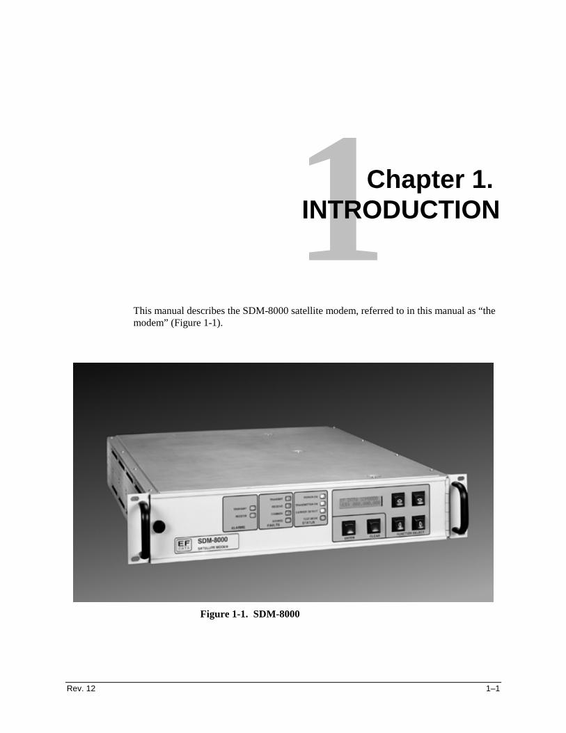
Rev. 12 1–1
1Chapter 1. INTRODUCTION
This manual describes the SDM-8000 satellite modem, referred to in this manual as “themodem” (Figure 1-1).
Figure 1-1. SDM-8000

Introduction SDM-8000 Satellite Modem
1–2 Rev. 12
1.1 Overview
The modem is a high performance, full-duplex, digital-vector modulator/demodulatorthat meets the open network requirements of the INTELSAT Earth Station Standards(IESS) -308, -309, and -310 emulation specifications for Intermediate Data Rate (IDR),INTELSAT Business Services (IBS), and Satellite Multiservice System (SMS).
The modem also can be used for any closed network and satellite communication systemapplications.
The modem supports the following main modes of operation:
• IDR (with Audio or 64 kbit/s data)• IBS• Drop and Insert (D&I)• Custom• Asynchronous overhead (ASYNC)• Type X (See Chapter 3, Table 3-5)
The modem interfaces between Single Channel Per Carrier (SCPC) fixed-rate terminalequipment operating within the following specifications:
• Data rate of 9.6 kbit/s to 9.312 Mbit/s• Symbol rate of 19 kS/s to 6.3 MS/s• Can be configured to add overhead/framing to the data
1.1.1 Modem Types
The modulation types include:
• Bi-Phase Shift Keying (BPSK)• Quadrature Phase Shift Keying (QPSK)• 8 Phase Shift Key (8PSK)• 16 Quadrature Amplitude Modulation (16QAM)
The Custom mode of operation enables the modem to emulate most proprietary modems.
The modem interfaces between the channel unit or multiplexer (MUX) and IntermediateFrequency (IF) converter equipment operating in a 50 to 180 MHz band. An internalchannel unit, conforming to IESS-308 and -309 emulation specifications, providesoverhead designated for an Engineering Service Circuit (ESC).
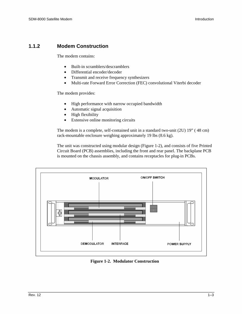
SDM-8000 Satellite Modem Introduction
Rev. 12 1–3
1.1.2 Modem Construction
The modem contains:
• Built-in scramblers/descramblers• Differential encoder/decoder• Transmit and receive frequency synthesizers• Multi-rate Forward Error Correction (FEC) convolutional Viterbi decoder
The modem provides:
• High performance with narrow occupied bandwidth• Automatic signal acquisition• High flexibility• Extensive online monitoring circuits
The modem is a complete, self-contained unit in a standard two-unit (2U) 19” ( 48 cm)rack-mountable enclosure weighing approximately 19 lbs (8.6 kg).
The unit was constructed using modular design (Figure 1-2), and consists of five PrintedCircuit Board (PCB) assemblies, including the front and rear panel. The backplane PCBis mounted on the chassis assembly, and contains receptacles for plug-in PCBs.
Figure 1-2. Modulator Construction

Introduction SDM-8000 Satellite Modem
1–4 Rev. 12
The front edge of the modulator, demodulator, and interface PCBs contains the test points.
The front panel of the modem contains all Monitor and Control (M&C) functionindicators for operating the modem. The display/M&C PCB is mounted on the frontpanel.
The chassis also contains a fan (on the rear panel) and a power supply.
Refer to Figure 1-3 for a system block diagram.
TRANSMITRF
EQUIPMENT
IF OUTPUTCP1ENCODER/
DATACLKSCT
M&C
SATELLITESDM-8000
DATA MODEM
INTERFACE
J8CUSTOMERDATA I/O
BOP(IB8004)
FAULTFORM C
CONTACTS
ALARMSFORM C
CONTACTSEXT.CLK.
J8
J10
J9M&C
COMMANDBUS
POWERSUPPLY
J9
IF INPUTDATA
M&C
J7
CLKAGC
M&C/DISPLAYKEYBOARD
J6
DECODERCLKAGC
CP2 RECEIVERF
EQUIPMENT
ANTENNA
AUX 1TTL FAULTS
REMOTESERIAL
INTERFACE
HSCLK
EXT. REF(OPTION)
90 to 264 VAC,47 to 63 Hz
50 to 90 MHz100 to 180 MHz-30 to -55 dBm
50 to 90 MHz100 to 180 MHz-5 to -30 dBm
MODULATOR
Figure 1-3. Block Diagram

SDM-8000 Satellite Modem Introduction
Rev. 12 1–5
1.2 Options
Refer to Table 1-1 for a description of module types that are compatible with eachoption.
Table 1-1. Module TypesConfiguration Interface Type FEC Option Options
70/140 MHz Duplex (AC) Standard Sequential +5 V Output70/140 MHz TX (AC) Standard with Buffer Viterbi 50Ω70/140 MHz RX (AC) Standard with Buffer/RS Int. SW Relay70/140 MHz Duplex (DC) Standard with Buffer/DVB RS Int. SW Relay 50Ω70/140 MHz TX (DC) IBS H/S 10-770/140 MHz RX (DC) IBS/IDR 2048 Max D/R
IBS/D&I with ACUIBS/RSIBS/D&I/RS with ACUIBS/IDR/D&I with ACUIBS/IDR/RSIBS/IDR/D&I/RS with ACUIBS with ACUIBS with ACU/IDRIBS/RS with ACUIBS/IDR/RS with ACU
Note: Viterbi decoder and 75Ω configuration are standard with the SDM-8000 Modem.
1.2.1 Sequential Decoder
The sequential decoder works in closed network applications which typically use theFrequency Division Multiple Access (FDMA) satellite communications system. Thedecoder also works in conjunction with the convolutional encoder at the transmittingmodem to correct bit errors in the received data stream from the demodulator.
For more information, refer to Appendix B.
Notes:1. D&I, and D&I with ASYNC options, can be used with the sequential decoder.2. The Reed-Solomon option cannot be used with the sequential decoder.3. The sequential decoder option will not function in 8PSK and 16QAM modes.

Introduction SDM-8000 Satellite Modem
1–6 Rev. 12
1.2.2 D&I with ASYNC Overhead
The D&I multiplexer with the ASYNC overhead data channel is used for earth station-to-earth station communication. The D&I multiplexer works in conjunction with theinterface PCB to enable the modem to transmit or receive fractional parts of a T1 datastream. The overhead channel is MUXed onto the data and transmitted at an overheadrate of 16/15 of the main channel.
For more information, refer to Appendix B.
Notes:1. D&I, and D&I with ASYNC options, can be used with the sequential decoder.2. The Reed-Solomon options cannot be used with the sequential decoder.
1.2.3 Reed-Solomon
The Reed-Solomon Codec works in conjunction with the Viterbi decoder and includesadditional framing, interleaving, and Codec processing to provide concatenated FEC, andconvolutional encoding and decoding.
Refer to Appendix B for more information.
Note: The sequential decoder cannot be used with the Reed-Solomon option.
1.2.4 8PSK
The 8PSK modulation type is a PSK encoding method for providing a modulated carrierat 38.4 kbit/s to 9.3 Mbit/s by pragmatic-trellis encoding at 2/3 rate.
Notes:1. The sequential decoder option cannot be used in the 8PSK mode.2. The D&I and Reed-Solomon options can be used in the 8PSK mode.
1.2.5 16QAM
The 16QAM is an encoding method for providing a modulated carrier at 50 kbit/s to9.3 Mbit/s in 3/4 rate, and 68 kbit/s to 9.3 Mbit/s in 7/8 rate.
Notes:1. The sequential decoder option cannot be used in the 16QAM mode.2. The Reed-Solomon option is required for 16QAM operation.
SDM-8000 Satellite Modem Introduction
Rev. 12 1–7
1.2.6 Interface Relay Board
The interface relay board option provides easy method for changing the data interface.The interface relay replaces the need to physically change the interface multi-pinjumpers by enabling data interface selections from the modem front panel.
For more information, refer to Appendix B.

Introduction SDM-8000 Satellite Modem
1–8 Rev. 12
1.3 Breakout Panels
Refer to Table 1-2 for the available breakout panels.
Table 1-2. Breakout Panel ConfigurationsBreakout
PanelDescription
UB-300 The UB-300 universal breakout panel functions as IDR, IBS, and D&I data breakoutpanels in one small rack-mountable unit. This breakout panel is used in 1:1 or M:Nswitching configurations. The UB-300 supplies convenient access to the SDM-308 Rev. 4ESC through a standard connector and to the 1/15 IBS overhead order wire, alarms,T1/E1, EIA-422/449, and V.35 data interfaces. The T1/E1 can be configured for balancedor unbalanced DATA I/O at the front panel through rear panel switches. The UB-300 alsoprovides standardized interfaces for D&I data. Both balanced and unbalanced interfacesfor drop DATA I/O and insert DATA I/O are provided, and are selectable through rearpanel DIP switches.
For more information, refer to the UB-300 Universal Breakout Panel Installation andOperation Manual.
IDR The IDR (B-308-4) breakout panel provides convenient access to the SDM-308 Rev. 4ESC components with industry standard connectors. The panel can be configured forbalanced or unbalanced DATA I/O at the rear panel DIP switches. This breakout panel isused in 1:1 or M:N switching configurations.
For more information, refer to the IDR Breakout Panel Installation and OperationManual.
IBS The IBS (B-309) breakout panel provides access to the 1/15 IBS overhead order wire andalarms. The panel also supports T1/E1, EIA-422/449, and V.35 data interfaces. T1/E1 canbe configured for balanced or unbalanced DATA I/O at the front panel with toggleswitches. This breakout panel is used in 1:1 or M:N switching configurations.
For more information, refer to the IBS Breakout Panel Installation and OperationManual.
IB-8004 The IB-8004 breakout panel provides convenient access to the SDM-308 Rev. 4 ESCcomponents and access to the 1/15 IBS overhead order wire and alarms. The panel alsosupports T1/E1, EIA-422/449, and V.35 data interfaces. This breakout panel is used in asingle modem configuration.
For more information, refer to the IB-8004 Breakout Panel Installation and OperationManual.
D&I The D&I (B-308-5) breakout panel provides standardized interfaces for the D&Icapabilities of the modem. The balanced and unbalanced interfaces for drop DATA I/Oand insert DATA I/O are provided and are selectable with rear panel DIP switches. Thisbreakout panel is used in 1:1 or M:N switching configurations.
For more information, refer to the D&I Breakout Panel Installation and OperationManual.
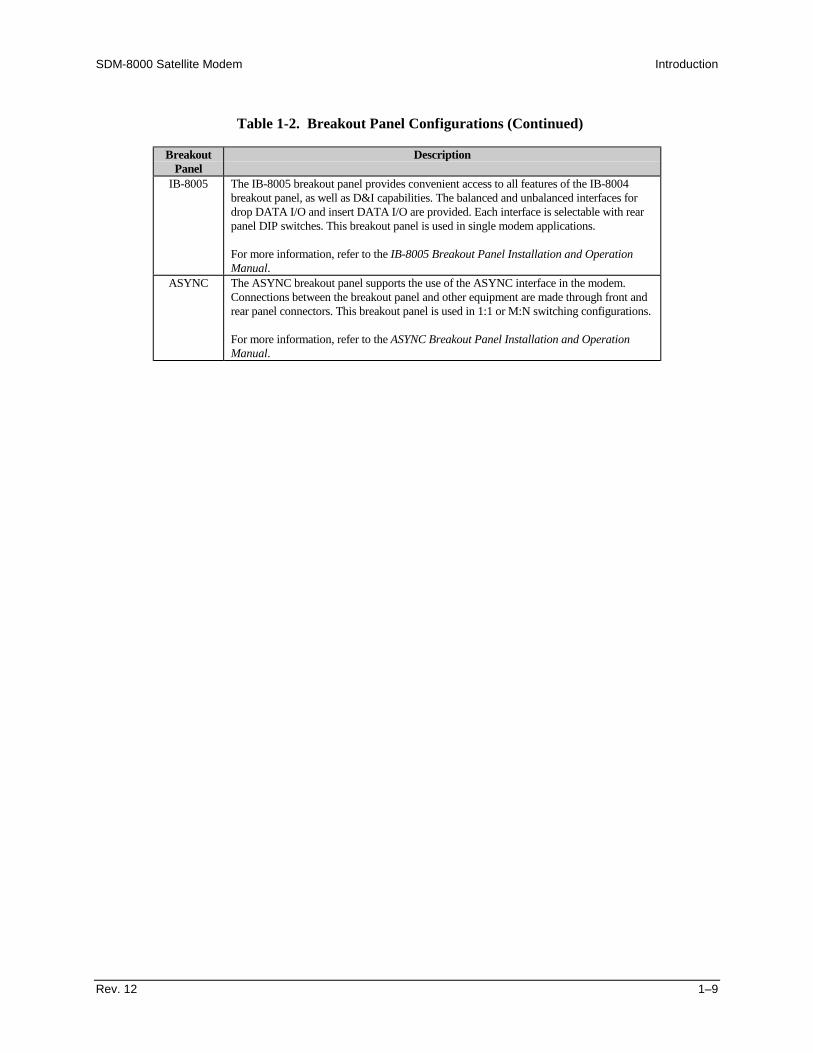
SDM-8000 Satellite Modem Introduction
Rev. 12 1–9
Table 1-2. Breakout Panel Configurations (Continued)
BreakoutPanel
Description
IB-8005 The IB-8005 breakout panel provides convenient access to all features of the IB-8004breakout panel, as well as D&I capabilities. The balanced and unbalanced interfaces fordrop DATA I/O and insert DATA I/O are provided. Each interface is selectable with rearpanel DIP switches. This breakout panel is used in single modem applications.
For more information, refer to the IB-8005 Breakout Panel Installation and OperationManual.
ASYNC The ASYNC breakout panel supports the use of the ASYNC interface in the modem.Connections between the breakout panel and other equipment are made through front andrear panel connectors. This breakout panel is used in 1:1 or M:N switching configurations.
For more information, refer to the ASYNC Breakout Panel Installation and OperationManual.

Introduction SDM-8000 Satellite Modem
1–10 Rev. 12
1.4 Modem Assemblies
Refer to Table 1-3 for modem assemblies.
Table 1-3. Modem Assemblies
Drawing # Assembly RemarksPL/2300-1 Assy, TopEIA-8000 Kit, Reed-SolomonPL/3606-1 Chassis, SDM-8000 ACPL/3606-2 Chassis, SDM-8000 DCPL/2305 Display/Monitor & Control No FW requiredPL/2487 Extender BoardPL/2876 Interface Switch Relay Board Optional Daughter BoardPL/3415-1 Modulator Card 50ΩPL/3415-2 Modulator Card 75Ω Repls PL/2302-2 QPSK onlyPL/3415-3 Modulator Card 50Ω, +5 dBmPL/3415-4 Modulator Card 75Ω, +5 dBm Repls PL/2302-4 QPSK onlyPL/3415-5 Modulator Card 50Ω, High Stability Option Alt P/N5039-5PL/3415-6 Modulator Card 75Ω, High Stability Option Repls PL/2302-6 QPSK onlyPL/3415-7 Modulator Card 50Ω, High Stability Option (+5 dBm) Alt P/N5039-7PL/3415-8 Modulator Card 75Ω, High Stability Option (+5 dBm) Alt P/N5039-8PL/3415-11 Modulator Card 50Ω, 8PSK/16QAMPL/3415-12 Modulator Card 75Ω, 8PSK,/16QAMPL/3415-13 Modulator Card 50Ω, +5 dBm 8PSK/16QAMPL/3415-14 Modulator Card 75Ω, +5 dBm 8PSK/16QAMPL/3415-15 Modulator Card 50Ω, High Stability Option 8PSK/16QAM Alt P/N5039-15PL/3415-16 Modulator Card 75Ω, High Stability Option 8PSK/16QAM Alt P/N5039-16PL/3415-17 Modulator Card 50Ω, High Stability Option (+5 dBm)
8PSK/16QAMAlt P/N5039-17
PL/3415-18 Modulator Card 75Ω, High Stability Option (+5 dBm)8PSK/16QAM
Alt P/N5039-18
PL/4895-1 Demodulator Card Viterbi 50Ω 8PSK/QPSK Repls PL3416-1PL/4895-2 Demodulator Card Viterbi 75Ω 8PSK/QPSK Repls PL3416-2PL/4895-3 Demodulator Card Viterbi 50Ω 8PSK/16QAM Repls PL3416-3PL/4895-4 Demodulator Card Viterbi 75Ω 8PSK/16QAM Repls PL3416-4PL/4895-5 Demodulator Card Viterbi/Sequential 50Ω 8PSK/QPSK Repls PL3416-1/3117PL/4895-6 Demodulator Card Viterbi/Sequential 75Ω 8PSK/QPSK Repls PL3416-2/3117PL/4895-7 Demodulator Card Viterbi/Sequential 50Ω 8PSK/16QAM Repls PL3416-3/3117PL/4895-8 Demodulator Card Viterbi/Sequential 75Ω 8PSK/16QAM Repls PL3416-4/3117
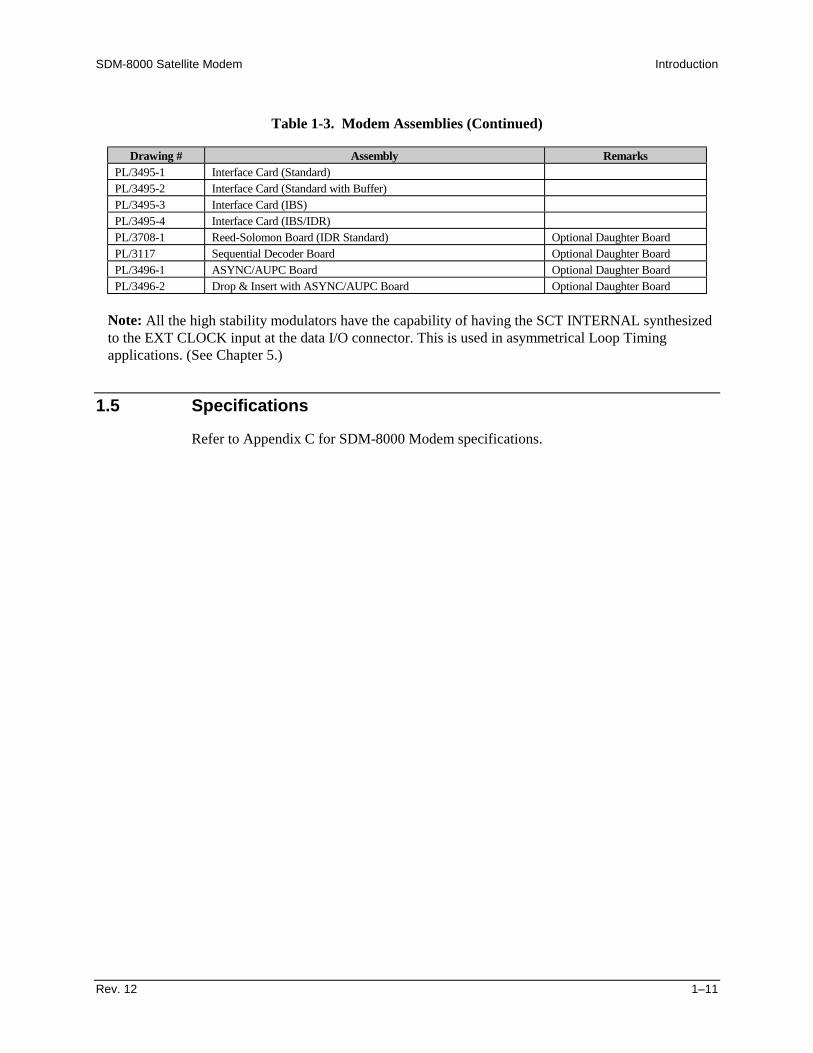
SDM-8000 Satellite Modem Introduction
Rev. 12 1–11
Table 1-3. Modem Assemblies (Continued)
Drawing # Assembly RemarksPL/3495-1 Interface Card (Standard)PL/3495-2 Interface Card (Standard with Buffer)PL/3495-3 Interface Card (IBS)PL/3495-4 Interface Card (IBS/IDR)PL/3708-1 Reed-Solomon Board (IDR Standard) Optional Daughter BoardPL/3117 Sequential Decoder Board Optional Daughter BoardPL/3496-1 ASYNC/AUPC Board Optional Daughter BoardPL/3496-2 Drop & Insert with ASYNC/AUPC Board Optional Daughter Board
Note: All the high stability modulators have the capability of having the SCT INTERNAL synthesizedto the EXT CLOCK input at the data I/O connector. This is used in asymmetrical Loop Timingapplications. (See Chapter 5.)
1.5 Specifications
Refer to Appendix C for SDM-8000 Modem specifications.
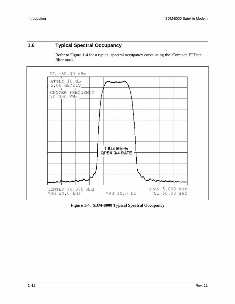
Introduction SDM-8000 Satellite Modem
1–12 Rev. 12
1.6 Typical Spectral Occupancy
Refer to Figure 1-4 for a typical spectral occupancy curve using the Comtech EFDatafilter mask.
Figure 1-4. SDM-8000 Typical Spectral Occupancy
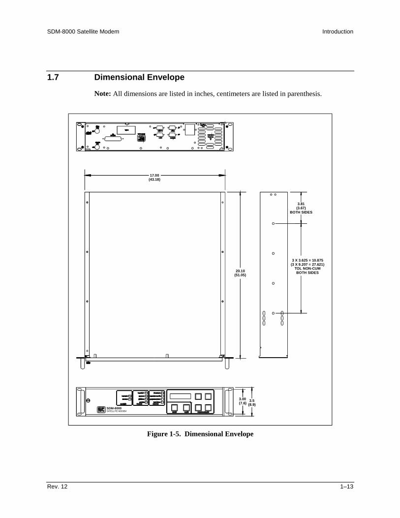
SDM-8000 Satellite Modem Introduction
Rev. 12 1–13
1.7 Dimensional Envelope
Note: All dimensions are listed in inches, centimeters are listed in parenthesis.
SDM-8000SATELLITE MODEM
3.81(3.67)
BOTH SIDES
3 X 3.625 = 10.875(3 X 9.207 = 27.621)
TOL NON-CUMBOTH SIDES20.10
(51.05)
17.00(43.18)
3.00(7.6) 3.5
(8.9)
Figure 1-5. Dimensional Envelope

Introduction SDM-8000 Satellite Modem
1–14 Rev. 12
This page is intentionally left blank.
Rev. 12 2–1
2Chapter 2. INSTALLATION
This chapter provides unpacking and installation instructions, system options, and adescription of external connections and backward alarm information.
CAUTION
The equipment contains parts and assemblies sensitive to damage byElectrostatic Discharge (ESD). Use ESD precautionary procedures whentouching, removing, or inserting PCBs.
2.1 Unpacking
The modem and manual are packaged in pre-formed, reusable, cardboard cartonscontaining foam spacing for maximum shipping protection. The circuit boards arepacked in separate cardboard caddypacks (also packaged within the cardboard carton).
CAUTION
Do not use any cutting tool that will extend more than 1” into the container.This can cause damage to the modem.
Remove the modem as follows:
1. Cut the tape at the top of the carton (indicated by OPEN THIS END).2. Remove the cardboard/foam space covering the modem and caddypacks.3. Remove the modem, caddypacks, manual, and power cord from the carton.4. Save the packing material for storage or reshipment purposes.5. Inspect the equipment for any possible damage incurred during shipment.6. Check the equipment against the packing list to ensure the shipment is correct.7. Refer to Section 2.3 for installation instructions.

Installation SDM-8000 Satellite Modem
2–2 Rev. 12
2.2 System Options
The standard modem with all PCB assemblies installed is a full-duplex QPSK satellitemodem. The system can also be configured for TX-only or RX-only operation:
• For a TX-only system, the demodulator PCB can be removed. Enter theSYSTEM UTILITY menu on the front panel and select Operation mode. Enterthe menu and select TX-only. This masks the receive faults and receive storedFAULTS in the Faults menu.
• For an RX-only system, the modulator PCB can be removed. Enter the SYSTEM
UTILITY menu on the front panel and select Operation mode. Enter the menuand select RX-only. This will mask the transmit faults and transmit stored faultsin the FAULTS menu.

SDM-8000 Satellite Modem Installation
Rev. 12 2–3
2.3 Installation
Refer to the following steps to install the modem:
1. Mount the modem (Figure 2-1) in the assigned position of the equipment rack.Support the modem by either a rack-mounted shelf, or the two rear rack-mountedbrackets supplied with the unit.
2. Connect the cables to the proper locations on the rear panel. Refer to Section 2.4for connector pinouts, placement, and function.
3. Refer to Chapter 3 to verify that all interface jumper settings are in the properposition.
4. Open the front panel and install the three main PCB assemblies:
a. Install the Modulator PCB (AS/3415-x or Alt AS/5039-x) in the top slot.b. Install the Interface PCB (AS/4895 or AS/3495) in the middle slot.c. Install the Demodulator PCB (AS/3416) in the bottom slot.
Note: The cards are keyed and will only fit in the proper chassis slot. Verifythat the PCBs are properly seated.
5. Before turning the power switch on, become familiar with front panel operationin Chapter 4.
6. Turn on the power switch located inside the front panel.
7. Check for the proper transmitter (TX) output signal level and spectrum.
8. Check for proper receiver (RX) input signal level and spectrum.
9. If there is any problem with the installation, refer to Chapter 6 fortroubleshooting information.
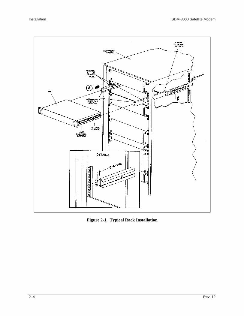
Installation SDM-8000 Satellite Modem
2–4 Rev. 12
Figure 2-1. Typical Rack Installation
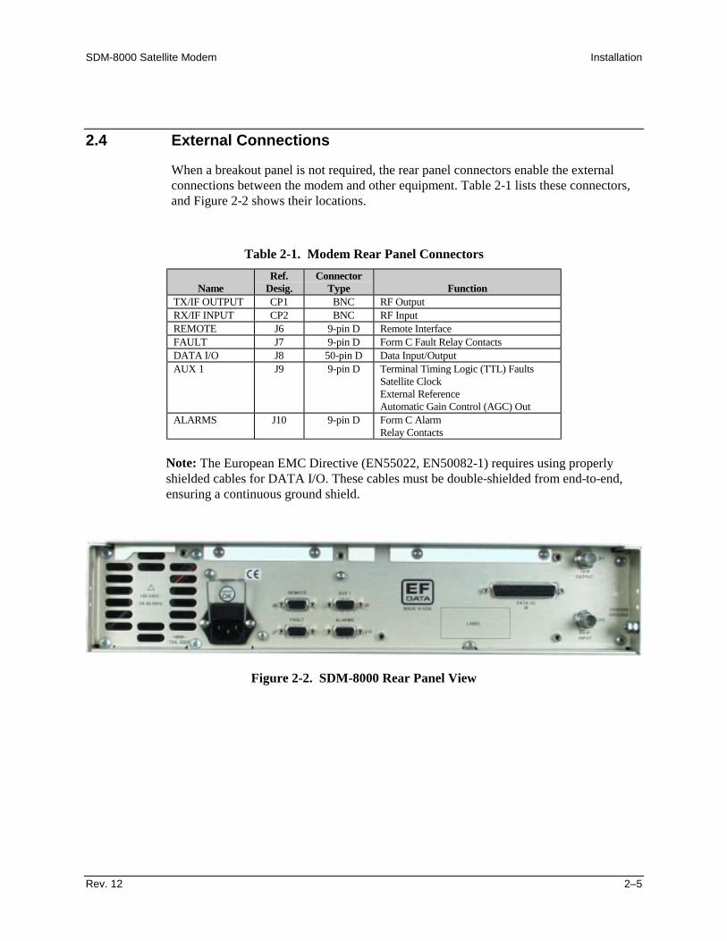
SDM-8000 Satellite Modem Installation
Rev. 12 2–5
2.4 External Connections
When a breakout panel is not required, the rear panel connectors enable the externalconnections between the modem and other equipment. Table 2-1 lists these connectors,and Figure 2-2 shows their locations.
Table 2-1. Modem Rear Panel Connectors
NameRef.
Desig.Connector
Type FunctionTX/IF OUTPUT CP1 BNC RF OutputRX/IF INPUT CP2 BNC RF InputREMOTE J6 9-pin D Remote InterfaceFAULT J7 9-pin D Form C Fault Relay ContactsDATA I/O J8 50-pin D Data Input/OutputAUX 1 J9 9-pin D Terminal Timing Logic (TTL) Faults
Satellite ClockExternal ReferenceAutomatic Gain Control (AGC) Out
ALARMS J10 9-pin D Form C AlarmRelay Contacts
Note: The European EMC Directive (EN55022, EN50082-1) requires using properlyshielded cables for DATA I/O. These cables must be double-shielded from end-to-end,ensuring a continuous ground shield.
Figure 2-2. SDM-8000 Rear Panel View

Installation SDM-8000 Satellite Modem
2–6 Rev. 12
2.4.1 RF Output Connector (CP1)
CP1 is a BNC connector for the TX IF signal.
The output impedance is 75Ω (50Ω optional), and the output power level is -5 to -30dBm. In normal operation, the output will be a QPSK modulated result of the DATA I/Oconnector between 50 and 180 MHz.
2.4.2 RF Input Connector (CP2)
CP2 is a BNC connector for the RX IF signal.
The input impedance is 75Ω (50Ω optional). For normal operation, the desired carriersignal level must be between -30 and -55 dBm. Signals between 50 and 180 MHz areselected and demodulated to produce clock and data at the DATA I/O connector.
2.4.3 Remote Connector and Pinouts (J6)
The remote connector interfaces the M&C functions to a remote location. This is a DCEinterface that can be either EIA-232 or EIA-485, refer to Table 2-2. Refer to Chapter 3for a description of the remote interface.
The remote interface connection is a 9-pin female D connector located on the rear panelof the modem. Screw locks are provided for mechanical security of the mating connector.
Table 2-2. Remote Connector and Pinouts (J6)EIA-485 EIA-232
4-Wire Mode 2-Wire ModePin # Name Name Pin # Name
1 GND GND 12 2 RD (RX)3 3 TD (TX)4 +TX +TX/RX* 45 -TX -TX/RX* 5 GND6 6 DSR7 7 RTS8 +RX +TX/RX* 8 CTS9 -RX -TX/RX* 9
• Either pair of Pins 4 and 5 or Pins 8 and 9 can be used in EIA-485, 2-wireapplications.
• The high signals for TX and RX are tied together. Consequently, the low signalsfor TX and RX are tied together

SDM-8000 Satellite Modem Installation
Rev. 12 2–7
2.4.4 Fault Connector and Pinouts (J7)
The fault connector provides Form C contact closures for fault reporting. The threeForm C summary fault contacts are Modulator, Demodulator, and Common Equipment,refer to Table 2-3. Refer to Chapter 4 for a discussion of faults monitored. To obtain asystem summary fault, connect all the Form C contacts in parallel.
The fault interface connection is a 9-pin female D connector located on the rear panel ofthe modem. Screw locks are provided for mechanical security on the mating connector.
Table 2-3. Fault Connector and Pinouts (J7)Signal Function Name Pin #
Common equipment is not faulted NO 1COM 2
Common equipment is faulted NC 3Modulator is not faulted NO 4
COM 5Modulator is faulted NC 6Demodulator is not faulted NO 7
COM 8Demodulator is faulted NC 9
Note: A connection between the common (COM) and normally open (NO) contactsindicates no fault
2.4.5 DATA I/O Interface Connector (J8)
The DATA I/O interface connector interfaces data input and output signals to and fromthe modem. The DATA I/O connects to the customer terrestrial equipment through abreakout panel or protection switch. The DATA I/O can be configured (depending onoptions) to IDR, IBS, or D&I types of interfaces. Refer to the MODEM UTILITYfunctions in Chapter 4 for configuration instructions. The DATA I/O pinout is differentfor each of the interface configurations.
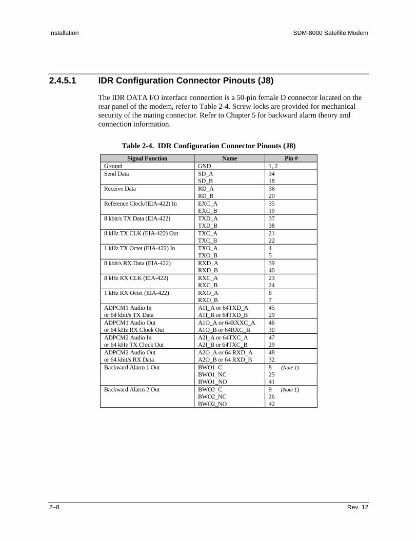
Installation SDM-8000 Satellite Modem
2–8 Rev. 12
2.4.5.1 IDR Configuration Connector Pinouts (J8)
The IDR DATA I/O interface connection is a 50-pin female D connector located on therear panel of the modem, refer to Table 2-4. Screw locks are provided for mechanicalsecurity of the mating connector. Refer to Chapter 5 for backward alarm theory andconnection information.
Table 2-4. IDR Configuration Connector Pinouts (J8)Signal Function Name Pin #
Ground GND 1, 2Send Data SD_A 34
SD_B 18Receive Data RD_A 36
RD_B 20Reference Clock/(EIA-422) In EXC_A 35
EXC_B 198 kbit/s TX Data (EIA-422) TXD_A 37
TXD_B 388 kHz TX CLK (EIA-422) Out TXC_A 21
TXC_B 221 kHz TX Octet (EIA-422) In TXO_A 4
TXO_B 58 kbit/s RX Data (EIA-422) RXD_A 39
RXD_B 408 kHz RX CLK (EIA-422) RXC_A 23
RXC_B 241 kHz RX Octet (EIA-422) RXO_A 6
RXO_B 7ADPCM1 Audio In A1I_A or 64TXD_A 45or 64 kbit/s TX Data A1I_B or 64TXD_B 29ADPCM1 Audio Out A1O_A or 64RXXC_A 46or 64 kHz RX Clock Out A1O_B or 64RXC_B 30ADPCM2 Audio In A2I_A or 64TXC_A 47or 64 kHz TX Clock Out A2I_B or 64TXC_B 29ADPCM2 Audio Out A2O_A or 64 RXD_A 48or 64 kbit/s RX Data A2O_B or 64 RXD_B 32Backward Alarm 1 Out BWO1_C 8 (Note 1)
BWO1_NC 25BWO1_NO 41
Backward Alarm 2 Out BWO2_C 9 (Note 1)BWO2_NC 26BWO2_NO 42

SDM-8000 Satellite Modem Installation
Rev. 12 2–9
Table 2-4. IDR Configuration Connector Pinouts (J8) (Continued)Signal Function Name Pin #
Backward Alarm 3 Out BWO3_C 10 (Note 1)BWO3_NC 27BWO3_NO 43
Backward Alarm 4 Out BWO4_C 11 (Note 1)BWO4_NC 28BWO4_NO 44
Backward Alarm 1 In BWI1 12 (Note 2)Backward Alarm 2 In BWI2 13 (Note 2)Backward Alarm 3 In BWI3 14 (Note 2)Backward Alarm 4 In BWI4 15 (Note 2)Modulator Fault MF 49 (Note 3)Demodulator Fault DF 33 (Note 3)Deferred Maintenance Alarm DMA 17 (Note 3)Demodulator Fault Relay DF_C 16 (Note 4)
DF_NO 50AGC Output AGC_OUT 3
Notes:1. Backward alarm relay contacts are named for normal no fault conditions
(BWOx-C connected to BWOx-NC if no fault).2. Backward alarm inputs must be grounded or pulled logic low to clear the alarm.3. Signals MF, DF, and DMA are open collector, high impedance if faulted. MF
and DF are used by a backup protection switch if the modem is used in aredundant system.
4. Relay contacts DF-C and DF-NO are named for faulted condition (DF-Cconnected to DF-NO unless demodulator [demod] fault).
2.4.5.1.1 Cable (CA/5876) Pin Assignments
Cable (CA/5876) is used at DB9 connector for the 64K EIA-422 option. The following isa pin assignment listing to the DB37 connector.
DB37 DB9 Name4 1 SDA33 6 SDB5 8 STA23 4 STB8 2 RTA26 7 RTB6 9 RDA24 5 RDB
1, 19, 20, 37 3 GND

Installation SDM-8000 Satellite Modem
2–10 Rev. 12
2.4.5.2 IBS Interface Connector Pinouts (J8)
The IBS interface connection is a 50-pin female D connector located on the rear panel ofthe modem, refer to Table 2-5. Screw locks are provided for mechanical security of themating connector. Refer to Chapter 5 for backward alarm theory and connectioninformation.
Table 2-5. IBS Interface Connector Pinouts (J8)Signal Function Name Pin #
Ground GND 1, 2T1/E1 Send Data T1E1_SDA 34
T1E1_SDB 18T1/E1 Receive Data T1E1_RDA 36
T1E1_RDB 20External Clock In EXC_A 35
EXC_B 19EIA-422/V.35 Send Data SD_A 37
SD_B 38EIA-422/V.35 Receive Data RD_A 39
RD_B 40Terrestrial TX Data TERESTXDAT 5Engineering Service Channel RXESCDAT 7EIA-422/V.35 Receive Timing SCR/RT_A 23
SCR/RT_B 24EIA-422/V.35 Transmit Timing SCT/ST_A 21
SCT/ST_B 22EIA-422/V.35 Terminal Timing SCTE/TT_A 12
SCTE/TT_B 13EIA-422 Transmit Octet R422TXO_A 14
R422TXO_A 15EIA-422 Receive Octet R422RXO_A 8
R422RXO_B 9EIA-422/V.35 Request To Send RTS_A 45
RTS_B 29ESC Data Set Ready (EIA-232 Only) ESC_DSR 41EIA-422/V.35 Clear To Send CTS_A 47
CTS_B 31EIA-422/V.35 Data Set Ready/ DSR/DM_A 48Data Mode DSR/DM_B 32EIA-422/V.35 Receive Line Signal RLSD/RR_A 46Detect/Receiver Ready RLSD/RR_B 30Primary Alarm Out PRI_COM 10
PRI_NO 43PRI_NC 27
Secondary Alarm Out SEC_COM 11SEC_NO 44SEC_NC 28
Modulator Fault MOD_FLT 49Demodulator Fault DEM_FLT 33AGC Output AGC_OUT 3
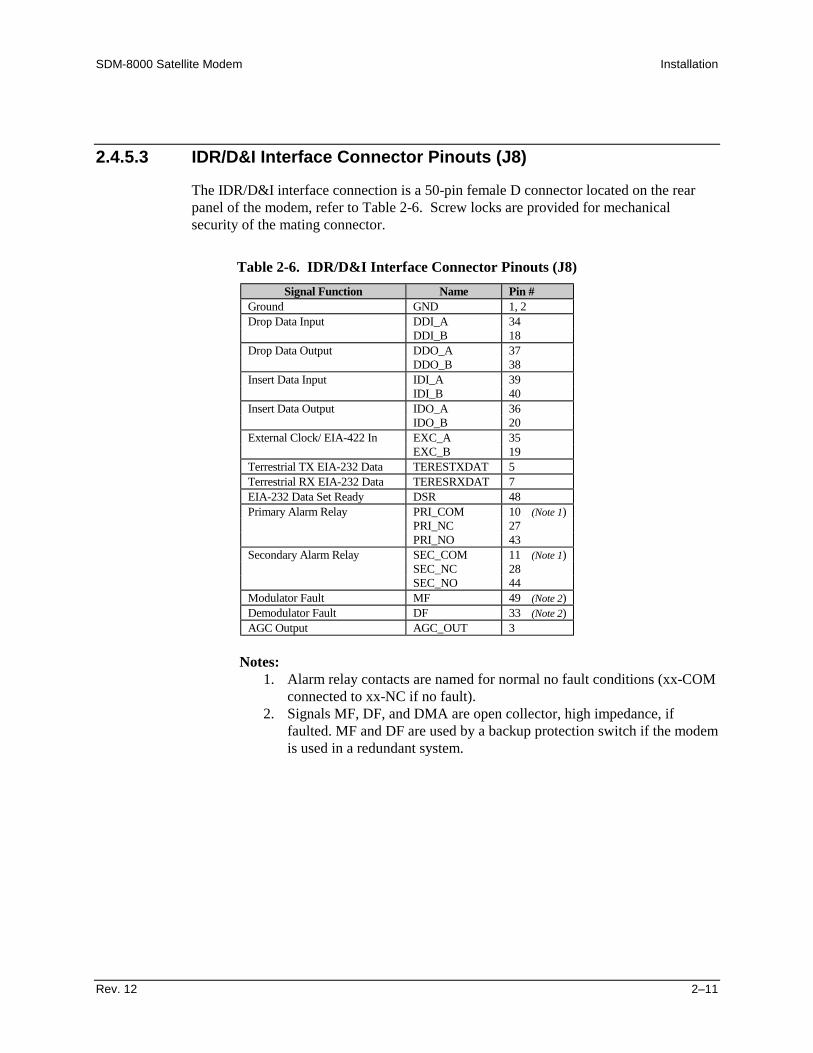
SDM-8000 Satellite Modem Installation
Rev. 12 2–11
2.4.5.3 IDR/D&I Interface Connector Pinouts (J8)
The IDR/D&I interface connection is a 50-pin female D connector located on the rearpanel of the modem, refer to Table 2-6. Screw locks are provided for mechanicalsecurity of the mating connector.
Table 2-6. IDR/D&I Interface Connector Pinouts (J8)Signal Function Name Pin #
Ground GND 1, 2Drop Data Input DDI_A 34
DDI_B 18Drop Data Output DDO_A 37
DDO_B 38Insert Data Input IDI_A 39
IDI_B 40Insert Data Output IDO_A 36
IDO_B 20External Clock/ EIA-422 In EXC_A 35
EXC_B 19Terrestrial TX EIA-232 Data TERESTXDAT 5Terrestrial RX EIA-232 Data TERESRXDAT 7EIA-232 Data Set Ready DSR 48Primary Alarm Relay PRI_COM 10 (Note 1)
PRI_NC 27PRI_NO 43
Secondary Alarm Relay SEC_COM 11 (Note 1)SEC_NC 28SEC_NO 44
Modulator Fault MF 49 (Note 2)Demodulator Fault DF 33 (Note 2)AGC Output AGC_OUT 3
Notes:1. Alarm relay contacts are named for normal no fault conditions (xx-COM
connected to xx-NC if no fault).2. Signals MF, DF, and DMA are open collector, high impedance, if
faulted. MF and DF are used by a backup protection switch if the modemis used in a redundant system.
Installation SDM-8000 Satellite Modem
2–12 Rev. 12
2.4.5.4 EIA-422 Data with IDR Overhead
The following procedure describes a path in which data can be passed using the EIA-422format while the unit is operating with IDR overhead. Normally, data in IDR mode issent in G.703 format and uses different pins in the Data I/O Interface Connector (J8).The only lines common between EIA-422 and IDR overhead are :
• EXT CLK• MOD Fault• Demod Fault
Perform the following procedure should be used with EIA-422 data applied to an IDRformat.
1. Set Utility/Modem Type to Custom.
2. Set Utility/Interface/TX Overhead Type to IDR.
3. Set Utility/Interface/RX Overhead Type to IDR.
Note: This will place the multiplexer and demultiplexer into operation. 4. Open the front panel and remove the Interface PCB (AS/4895 or AS/3495).
a. For IBS Only - Set jumpers for EIA-422 at JP2, JP3, and JP5.
b. For IDR Only - Set the jumpers for EIA-422 at JP1, JP7, JP22, and JP23.
Note: This completes the transition from regular IDR to EIA-422.
5. Install Data I/O Connector J8 to 8004 Breakout panel.
Note: This will transition the 50-pin connector to a 37-pin connector, allowingonly the necessary pins to be used.
The remaining regular IDR overhead functions are:
• The four Backward Alarms Outputs• The Backward Alarm Input 3 and 4.
In addition, Backward Alarms 1, 3, and 4 are disabled. They share a jumper (JP2) withTT/BW11 and 2 selection, because BW1, 3, and 4 share pins with an overhead functionused in IBS mode.Backward Alarms 1, 3, and 4 can be enabled, but it would benecessary to split the ganged jumper into individual shunts. Contact Comtech EFDataCustomer Support for additional information.

SDM-8000 Satellite Modem Installation
Rev. 12 2–13
The operator may regain both audio channels by disabling the following:
• Request To Send (RTS)• Clear To Send (CTS)• Receiver Ready (RR)• Data Mode (DM)
Notes:1. Leave JP3 in the IDR position.2. Set JP2 and JP 5 to IBS mode.
2.4.6 Auxiliary 1 Connector and Pinouts (J9)
The auxiliary 1 (AUX 1) connector provides:
• Terminal Timing Logic (TTL) faults• Satellite clock signals• External reference• Automatic Gain Control (AGC) output voltage
The faults are open collector levels that indicate a modulator or demodulator failure. Alogic “1” indicates the faulted condition. The external reference clock input is 5, 10, or20 MHz.
AGC_OUT is the voltage for a receive signal level between -25 and -60 dBm.
AUX 1 connection is a 9-pin female D connector located on the rear panel of the modem,refer to Table 2-7. Screw locks are provided for mechanical security on the matingconnector.
Table 2-7. Auxiliary 1 Connector and Pinouts (J9)Signal Function Name Pin #
Satellite clock- SAT_CLK- 1External reference- EXT_REF 2 (see Note)Satellite clock+ SAT_CLK+ 3Modulator fault- MDTTLFLT 4Ground- GND 5Ground GND 6Demodulator fault- DMTTLFLT 7Ground GND 8AGC Out AGC Out 9
Note: This is an unbalanced input for a high stability site reference of either 5, 10, or 20MHz. Comtech EFData recommends that the Modualtor PCB include the high stabilityoption (to be used in Ext Ref input) for the modem to accept the site reference of 5, 10,or 20 MHz.
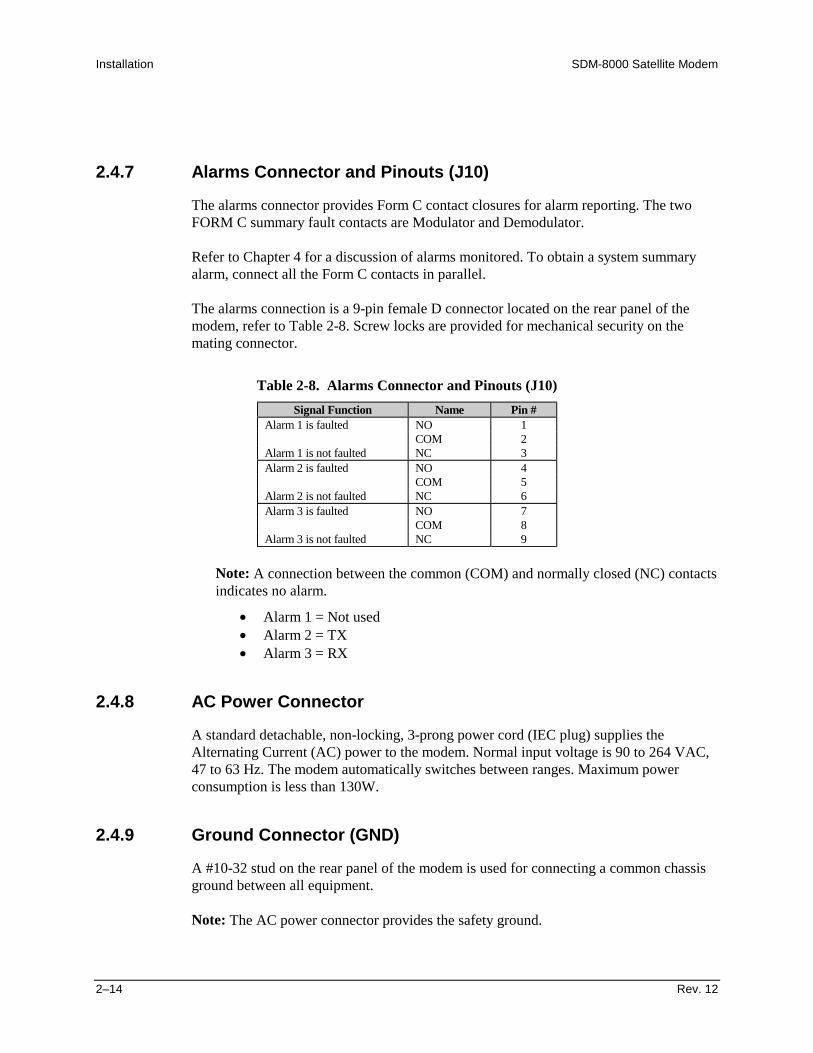
Installation SDM-8000 Satellite Modem
2–14 Rev. 12
2.4.7 Alarms Connector and Pinouts (J10)
The alarms connector provides Form C contact closures for alarm reporting. The twoFORM C summary fault contacts are Modulator and Demodulator.
Refer to Chapter 4 for a discussion of alarms monitored. To obtain a system summaryalarm, connect all the Form C contacts in parallel.
The alarms connection is a 9-pin female D connector located on the rear panel of themodem, refer to Table 2-8. Screw locks are provided for mechanical security on themating connector.
Table 2-8. Alarms Connector and Pinouts (J10)Signal Function Name Pin #
Alarm 1 is faulted NO 1COM 2
Alarm 1 is not faulted NC 3Alarm 2 is faulted NO 4
COM 5Alarm 2 is not faulted NC 6Alarm 3 is faulted NO 7
COM 8Alarm 3 is not faulted NC 9
Note: A connection between the common (COM) and normally closed (NC) contactsindicates no alarm.
• Alarm 1 = Not used• Alarm 2 = TX• Alarm 3 = RX
2.4.8 AC Power Connector
A standard detachable, non-locking, 3-prong power cord (IEC plug) supplies theAlternating Current (AC) power to the modem. Normal input voltage is 90 to 264 VAC,47 to 63 Hz. The modem automatically switches between ranges. Maximum powerconsumption is less than 130W.
2.4.9 Ground Connector (GND)
A #10-32 stud on the rear panel of the modem is used for connecting a common chassisground between all equipment.
Note: The AC power connector provides the safety ground.
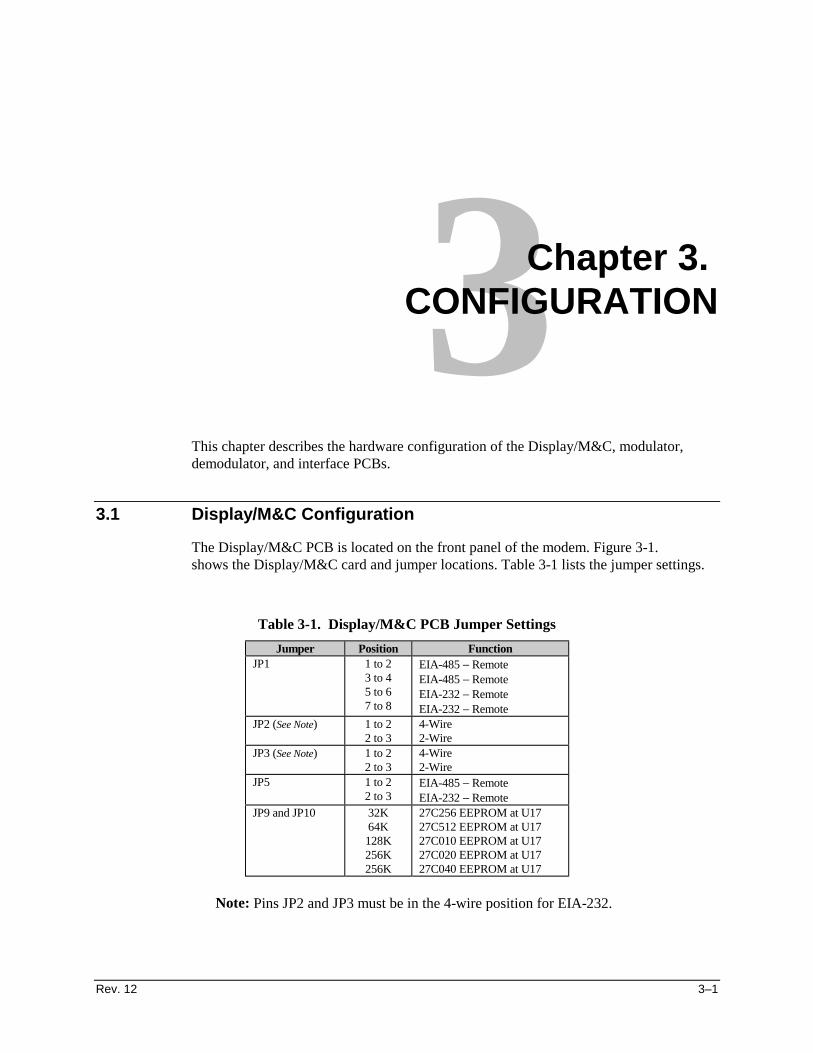
Rev. 12 3–1
3Chapter 3. CONFIGURATION
This chapter describes the hardware configuration of the Display/M&C, modulator,demodulator, and interface PCBs.
3.1 Display/M&C Configuration
The Display/M&C PCB is located on the front panel of the modem. Figure 3-1.shows the Display/M&C card and jumper locations. Table 3-1 lists the jumper settings.
Table 3-1. Display/M&C PCB Jumper SettingsJumper Position Function
JP1 1 to 23 to 45 to 67 to 8
EIA-485 − RemoteEIA-485 − RemoteEIA-232 − RemoteEIA-232 − Remote
JP2 (See Note) 1 to 22 to 3
4-Wire2-Wire
JP3 (See Note) 1 to 22 to 3
4-Wire2-Wire
JP5 1 to 22 to 3
EIA-485 − RemoteEIA-232 − Remote
JP9 and JP10 32K64K128K256K256K
27C256 EEPROM at U1727C512 EEPROM at U1727C010 EEPROM at U1727C020 EEPROM at U1727C040 EEPROM at U17
Note: Pins JP2 and JP3 must be in the 4-wire position for EIA-232.
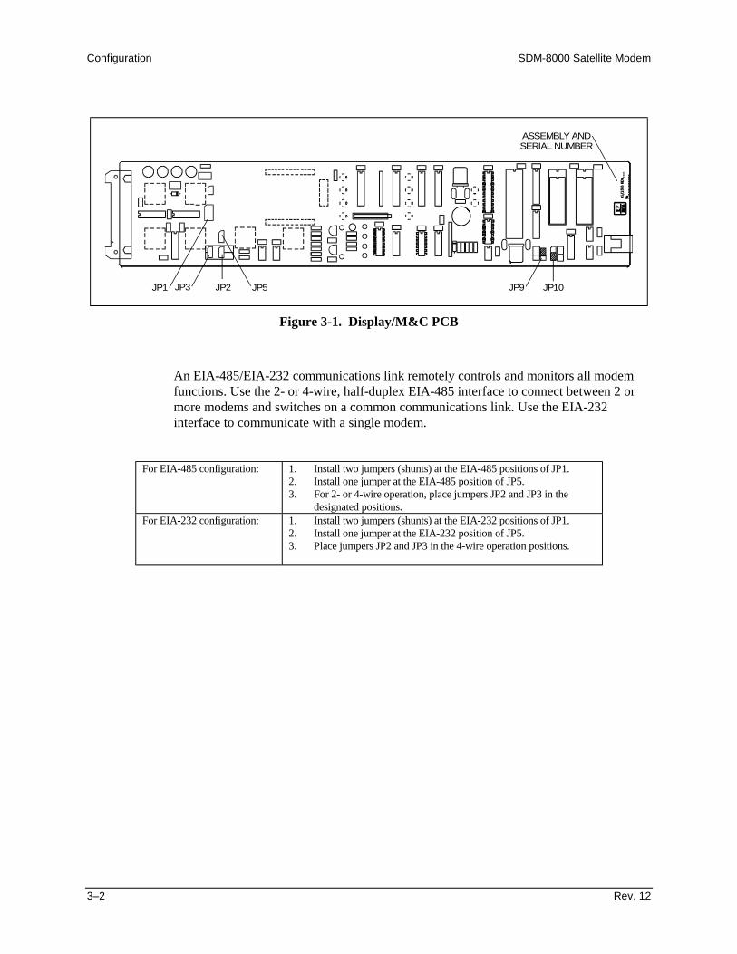
Configuration SDM-8000 Satellite Modem
3–2 Rev. 12
JP1 JP3 JP9JP2 JP10JP5
ASSEMBLY ANDSERIAL NUMBER
Figure 3-1. Display/M&C PCB
An EIA-485/EIA-232 communications link remotely controls and monitors all modemfunctions. Use the 2- or 4-wire, half-duplex EIA-485 interface to connect between 2 ormore modems and switches on a common communications link. Use the EIA-232interface to communicate with a single modem.
For EIA-485 configuration: 1. Install two jumpers (shunts) at the EIA-485 positions of JP1.2. Install one jumper at the EIA-485 position of JP5.3. For 2- or 4-wire operation, place jumpers JP2 and JP3 in the
designated positions.For EIA-232 configuration: 1. Install two jumpers (shunts) at the EIA-232 positions of JP1.
2. Install one jumper at the EIA-232 position of JP5.3. Place jumpers JP2 and JP3 in the 4-wire operation positions.

SDM-8000 Satellite Modem Configuration
Rev. 12 3–3
3.1.1 Remote Baud Rate
The remote communications baud rate and parity are programmed by the front panelcontrol in the Utility System menu (refer to Chapter 4). The programmed baud rate andparity are maintained indefinitely in Random Access Memory (RAM) on the M&Cmodule. The parity bits can be set to EVEN or ODD. The available baud rates are listedbelow:
• 110• 150• 300• 600• 1200• 2400• 4800• 9600• 19200
3.1.2 Remote Address
To communicate with the established remote communications protocol, configure eachmodem for one address between 1 and 255. Each modem on a common remotecommunications link (EIA-485) must have a distinct address. Use the front panel controlin the Utility System menu (Chapter 4) to program the addresses.
Note: Address 0 is reserved as a global address which simultaneously addresses alldevices on a given communications link.
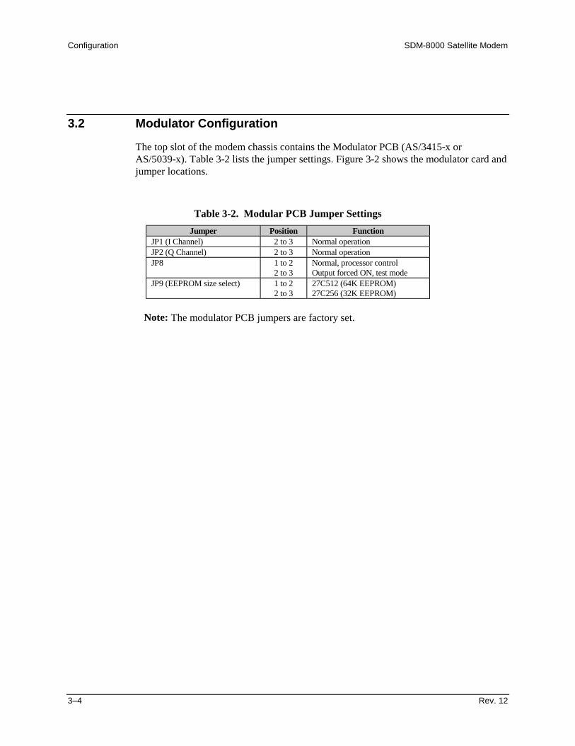
Configuration SDM-8000 Satellite Modem
3–4 Rev. 12
3.2 Modulator Configuration
The top slot of the modem chassis contains the Modulator PCB (AS/3415-x orAS/5039-x). Table 3-2 lists the jumper settings. Figure 3-2 shows the modulator card andjumper locations.
Table 3-2. Modular PCB Jumper SettingsJumper Position Function
JP1 (I Channel) 2 to 3 Normal operationJP2 (Q Channel) 2 to 3 Normal operationJP8 1 to 2
2 to 3Normal, processor controlOutput forced ON, test mode
JP9 (EEPROM size select) 1 to 22 to 3
27C512 (64K EEPROM)27C256 (32K EEPROM)
Note: The modulator PCB jumpers are factory set.

SDM-8000 Satellite Modem Configuration
Rev. 12 3–5
XXXX
JP8
JP9
JP1
ASSEMBLY NUMBERAND REVISION
JP2
Figure 3-2. Modulator PCB

Configuration SDM-8000 Satellite Modem
3–6 Rev. 12
3.3 Demodulator Configuration
The bottom slot of the modem chassis contains the Demodulator PCB (AS/4895-x).Table 3-3 lists the jumper settings. Figure 3-3 shows the demodulator card and jumperlocations.
Table 3-3. Demodulator PCB Jumper SettingsJumper Position Function
JP6 2 to 3 Normal operationJ7 and J8 N/A Sequential Decoder OptionJP8 (EEPROM size select) 1 to 2
2 to 327C256 (32K EEPROM)27C512 (64K EEPROM)
Note: The demodulator PCB jumpers are factory set.
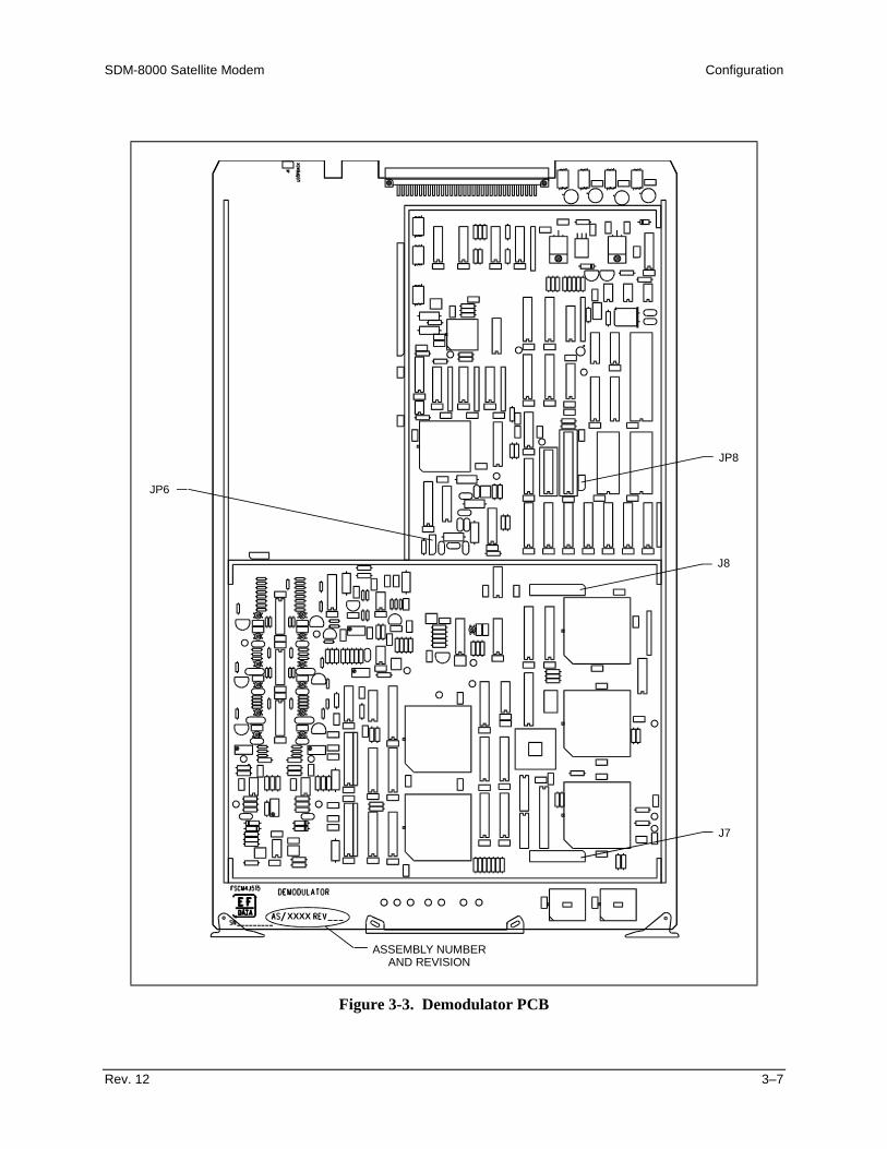
SDM-8000 Satellite Modem Configuration
Rev. 12 3–7
XXXX
JP6
JP8
J7
ASSEMBLY NUMBERAND REVISION
J8
Figure 3-3. Demodulator PCB

Configuration SDM-8000 Satellite Modem
3–8 Rev. 12
3.4 Interface Configuration
The Interface PCB (AS/3495-x) is located in the middle slot of the modem chassis.
The interface PCB has jumpers that must be set for various modes of operation.Table 3-4 lists the interface PCB jumper settings for all available options. Figure 3-4shows the jumper locations. The silk-screen on the interface PCB includes all necessaryjumper information.
Note: For proper jumper installation, position the interface PCB with the ejector enddirectly in front of the user. An “X” indicates a “don’t care” state for a jumper.
Table 3-4. Interface Configuration Jumper SettingsIDR IBS
Jumpers Standard 64K Option G.703 V.35 EIA-422 D&IJP1 X Left X Right Left X (EIA-422)JP2 Right Right Left Left Left IBSJP3 Right Left Left Left Left LeftJP4 N/A N/A N/A N/A N/AJP5 Right Right Left Left Left IBSJP7 OFF OFF OFF Right Left OFFJP8 N/A N/A N/A N/A N/AJP16 (Note 2) Factory Set Factory Set Factory Set Factory Set Factory SetJP22 OFF OFF OFF Right Left OFFJP23 OFF Left OFF Right Left OFF
G.703 Levels
High DriveNominal
LevelNominalShaped
LowLevel
LowShaped
JP9 OFF OFF ON OFF ONJP10 OFF OFF OFF ON ONJP11 OFF OFF OFF OFF OFF

SDM-8000 Satellite Modem Configuration
Rev. 12 3–9
Notes:1. For proper jumper installation, position the interface PCB with the ejector
end directly in front of the user. An “X” indicates a “don’t care” state for ajumper.
2. An interface relay board option is available. This option provides an easymethod for changing the data interface. The relay board replaces the need tophysically change the multi-pin jumpers by enabling the user to select datainterfaces from the modem front panel. Set VP16 in the 64K position whenusing the interface relay board. The firmware for the M&C must be≥ FW/2448-1K
3. D&I 308-5 Rev. 6 specifications require all jumpers to be set to IBS.4. In D&I mode, JP2, JP3, and JP5 may be set to IDR when not using overhead.5. The following table lists the minimum firmware upgrade requirements
needed to enable the 64 kbit feature:
Card Location FirmwareM&C U17 FW/2448-1VInterface U109 and U110 FW/2882-MInterface U111 FW/2451-2V

Configuration SDM-8000 Satellite Modem
3–10 Rev. 12
XXXX
JP16
JP3
JP11
JP9
JP5
JP1
JP23
JP22
ASSEMBLY NUMBERAND REVISION
JP2
JP7
JP10
Figure 3-4. Interface PCB
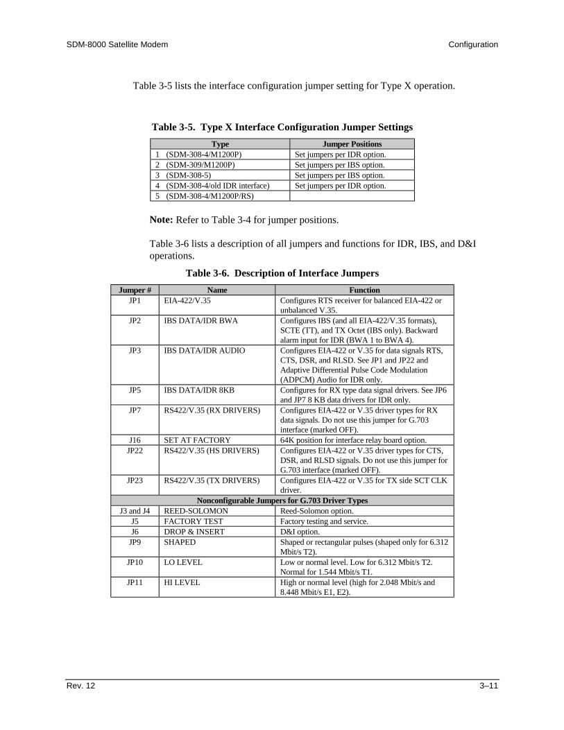
SDM-8000 Satellite Modem Configuration
Rev. 12 3–11
Table 3-5 lists the interface configuration jumper setting for Type X operation.
Table 3-5. Type X Interface Configuration Jumper SettingsType Jumper Positions
1 (SDM-308-4/M1200P) Set jumpers per IDR option.2 (SDM-309/M1200P) Set jumpers per IBS option.3 (SDM-308-5) Set jumpers per IBS option.4 (SDM-308-4/old IDR interface) Set jumpers per IDR option.5 (SDM-308-4/M1200P/RS)
Note: Refer to Table 3-4 for jumper positions.
Table 3-6 lists a description of all jumpers and functions for IDR, IBS, and D&Ioperations.
Table 3-6. Description of Interface JumpersJumper # Name Function
JP1 EIA-422/V.35 Configures RTS receiver for balanced EIA-422 orunbalanced V.35.
JP2 IBS DATA/IDR BWA Configures IBS (and all EIA-422/V.35 formats),SCTE (TT), and TX Octet (IBS only). Backwardalarm input for IDR (BWA 1 to BWA 4).
JP3 IBS DATA/IDR AUDIO Configures EIA-422 or V.35 for data signals RTS,CTS, DSR, and RLSD. See JP1 and JP22 andAdaptive Differential Pulse Code Modulation(ADPCM) Audio for IDR only.
JP5 IBS DATA/IDR 8KB Configures for RX type data signal drivers. See JP6and JP7 8 KB data drivers for IDR only.
JP7 RS422/V.35 (RX DRIVERS) Configures EIA-422 or V.35 driver types for RXdata signals. Do not use this jumper for G.703interface (marked OFF).
J16 SET AT FACTORY 64K position for interface relay board option.JP22 RS422/V.35 (HS DRIVERS) Configures EIA-422 or V.35 driver types for CTS,
DSR, and RLSD signals. Do not use this jumper forG.703 interface (marked OFF).
JP23 RS422/V.35 (TX DRIVERS) Configures EIA-422 or V.35 for TX side SCT CLKdriver.
Nonconfigurable Jumpers for G.703 Driver TypesJ3 and J4 REED-SOLOMON Reed-Solomon option.
J5 FACTORY TEST Factory testing and service.J6 DROP & INSERT D&I option.
JP9 SHAPED Shaped or rectangular pulses (shaped only for 6.312Mbit/s T2).
JP10 LO LEVEL Low or normal level. Low for 6.312 Mbit/s T2.Normal for 1.544 Mbit/s T1.
JP11 HI LEVEL High or normal level (high for 2.048 Mbit/s and8.448 Mbit/s E1, E2).

Configuration SDM-8000 Satellite Modem
3–12 Rev. 12
3.5 Software Configuration
This section consists of the following software information:
• Configuration of modem types• Revision emulation• Modem emulation• Remote interface specification• Modem defaults
3.5.1 Modem Types
The modem can be configured to the types of operation specified in Table 3-7. Eachmode allows the modem to operate under the requirements of the following configurationspecifications.
Table 3-7. Modem TypesConfiguration Specification
IDR IESS-308IBS IESS-309D&I IESS-308-5Custom Access all modesASYNC AUPC and closed network overheadType X (1 to 5) Access SDM-308/309 modems
Note: To program an evaluation mode of a previous functional revision, use the revisionemulation feature in the Utility menu. Refer to Chapter 4 for more information.
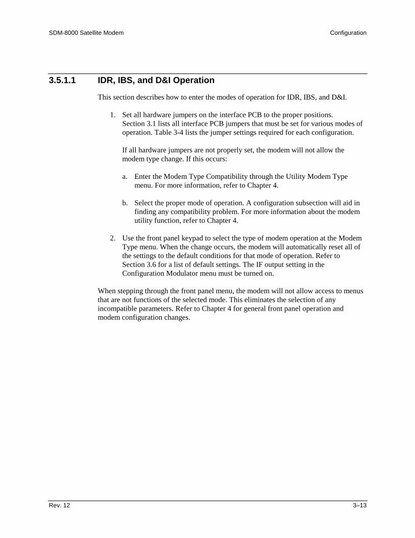
SDM-8000 Satellite Modem Configuration
Rev. 12 3–13
3.5.1.1 IDR, IBS, and D&I Operation
This section describes how to enter the modes of operation for IDR, IBS, and D&I.
1. Set all hardware jumpers on the interface PCB to the proper positions.Section 3.1 lists all interface PCB jumpers that must be set for various modes ofoperation. Table 3-4 lists the jumper settings required for each configuration.
If all hardware jumpers are not properly set, the modem will not allow themodem type change. If this occurs:
a. Enter the Modem Type Compatibility through the Utility Modem Typemenu. For more information, refer to Chapter 4.
b. Select the proper mode of operation. A configuration subsection will aid infinding any compatibility problem. For more information about the modemutility function, refer to Chapter 4.
2. Use the front panel keypad to select the type of modem operation at the ModemType menu. When the change occurs, the modem will automatically reset all ofthe settings to the default conditions for that mode of operation. Refer toSection 3.6 for a list of default settings. The IF output setting in theConfiguration Modulator menu must be turned on.
When stepping through the front panel menu, the modem will not allow access to menusthat are not functions of the selected mode. This eliminates the selection of anyincompatible parameters. Refer to Chapter 4 for general front panel operation andmodem configuration changes.
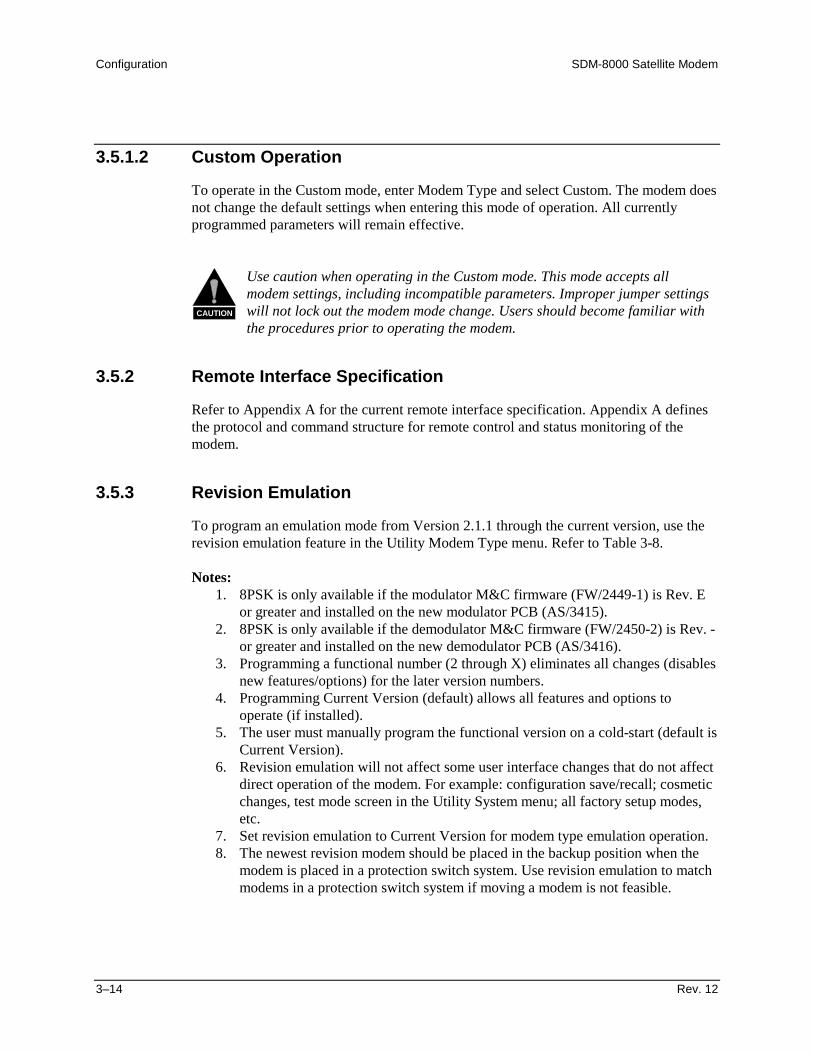
Configuration SDM-8000 Satellite Modem
3–14 Rev. 12
3.5.1.2 Custom Operation
To operate in the Custom mode, enter Modem Type and select Custom. The modem doesnot change the default settings when entering this mode of operation. All currentlyprogrammed parameters will remain effective.
CAUTION
Use caution when operating in the Custom mode. This mode accepts allmodem settings, including incompatible parameters. Improper jumper settingswill not lock out the modem mode change. Users should become familiar withthe procedures prior to operating the modem.
3.5.2 Remote Interface Specification
Refer to Appendix A for the current remote interface specification. Appendix A definesthe protocol and command structure for remote control and status monitoring of themodem.
3.5.3 Revision Emulation
To program an emulation mode from Version 2.1.1 through the current version, use therevision emulation feature in the Utility Modem Type menu. Refer to Table 3-8.
Notes:1. 8PSK is only available if the modulator M&C firmware (FW/2449-1) is Rev. E
or greater and installed on the new modulator PCB (AS/3415).2. 8PSK is only available if the demodulator M&C firmware (FW/2450-2) is Rev. -
or greater and installed on the new demodulator PCB (AS/3416).3. Programming a functional number (2 through X) eliminates all changes (disables
new features/options) for the later version numbers.4. Programming Current Version (default) allows all features and options to
operate (if installed).5. The user must manually program the functional version on a cold-start (default is
Current Version).6. Revision emulation will not affect some user interface changes that do not affect
direct operation of the modem. For example: configuration save/recall; cosmeticchanges, test mode screen in the Utility System menu; all factory setup modes,etc.
7. Set revision emulation to Current Version for modem type emulation operation.8. The newest revision modem should be placed in the backup position when the
modem is placed in a protection switch system. Use revision emulation to matchmodems in a protection switch system if moving a modem is not feasible.
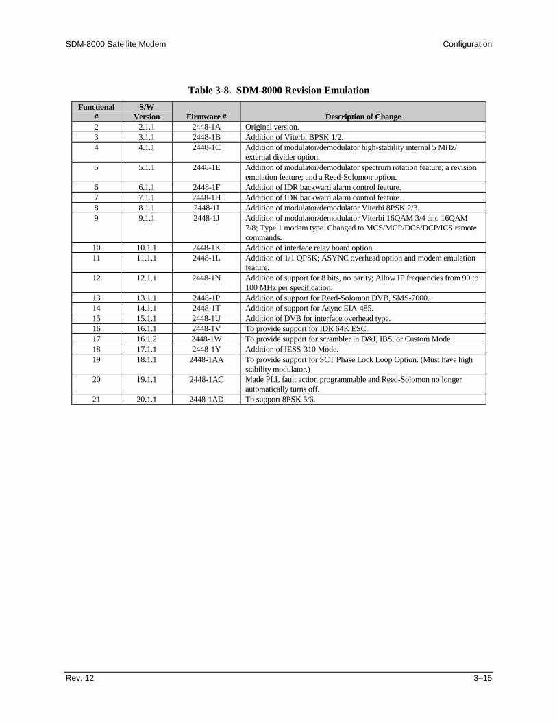
SDM-8000 Satellite Modem Configuration
Rev. 12 3–15
Table 3-8. SDM-8000 Revision EmulationFunctional
#S/W
Version Firmware # Description of Change2 2.1.1 2448-1A Original version.3 3.1.1 2448-1B Addition of Viterbi BPSK 1/2.4 4.1.1 2448-1C Addition of modulator/demodulator high-stability internal 5 MHz/
external divider option.5 5.1.1 2448-1E Addition of modulator/demodulator spectrum rotation feature; a revision
emulation feature; and a Reed-Solomon option.6 6.1.1 2448-1F Addition of IDR backward alarm control feature.7 7.1.1 2448-1H Addition of IDR backward alarm control feature.8 8.1.1 2448-1I Addition of modulator/demodulator Viterbi 8PSK 2/3.9 9.1.1 2448-1J Addition of modulator/demodulator Viterbi 16QAM 3/4 and 16QAM
7/8; Type 1 modem type. Changed to MCS/MCP/DCS/DCP/ICS remotecommands.
10 10.1.1 2448-1K Addition of interface relay board option.11 11.1.1 2448-1L Addition of 1/1 QPSK; ASYNC overhead option and modem emulation
feature.12 12.1.1 2448-1N Addition of support for 8 bits, no parity; Allow IF frequencies from 90 to
100 MHz per specification.13 13.1.1 2448-1P Addition of support for Reed-Solomon DVB, SMS-7000.14 14.1.1 2448-1T Addition of support for Async EIA-485.15 15.1.1 2448-1U Addition of DVB for interface overhead type.16 16.1.1 2448-1V To provide support for IDR 64K ESC.17 16.1.2 2448-1W To provide support for scrambler in D&I, IBS, or Custom Mode.18 17.1.1 2448-1Y Addition of IESS-310 Mode.19 18.1.1 2448-1AA To provide support for SCT Phase Lock Loop Option. (Must have high
stability modulator.)20 19.1.1 2448-1AC Made PLL fault action programmable and Reed-Solomon no longer
automatically turns off.21 20.1.1 2448-1AD To support 8PSK 5/6.

Configuration SDM-8000 Satellite Modem
3–16 Rev. 12
3.5.4 Modem Emulation
Table 3-9 lists the types of modem emulations this modem handles. This allows themodem to be used in place of the following pre-existing modems in a rack system. Theemulation is identified by Type X, where X is the number of the emulation type (1through 5).
Refer to the front panel menus in Chapter 4 to set up the modem for Type 1 through 5operation. Table 3-10 list the modem emulation software and operating requirements.
Table 3-9. Modem Emulation TypesType X Modem Emulation Operation
1 SDM-308-4/M1200P IDR2 SDM-309/M1200P IBS3 SDM-308-5 IBS4 SDM-308-4 (old IDR interface) IDR5 SDM-308-4/M1200P/RS

SDM-8000 Satellite Modem Configuration
Rev. 12 3–17
Table 3-10. Modem EmulationType 1
Modem Firmware Version Description of ChangeSDM-308-4/1200P 0713-61D
0713-61C0713-61B0713-61A0713-61-0713-23I0713-23H0713-23G0713-23F
6.046.036.026.016.003.093.083.073.06
1. 70/140 MHz modulator/demodulator.2. 16.0 dB Eb/N0.3 Variable modulator/demodulator filters.4. N/A not allowed for rate assignments.5. Displays 99% instead of No Data for buffer fill status.6. Allow transmit clock source of EXT_reference
regardless of EXT REF FREQ. SDM-8000 TX datarate must match EXT REF FREQ. SDM-8000 isprogrammable.
Type 2Modem Firmware Version Description of Change
SDM-309/1200P 0713-59C0713-59B0713-59A0713-59-0713-56A
6.036.026.016.004.01
1. 70/140 MHz modulator/demodulator.2. 16.0 dB Eb/N0.3 Variable modulator/demodulator filters.4. N/A not allowed for rate assignments.5. Displays 99% instead of No Data for buffer fill status.6. Allow transmit clock source of EXT_reference
regardless of EXT REF FREQ. SDM-8000 TX datarate must match EXT REF FREQ. SDM-309 isprogrammable.
Type 3Modem Firmware Version Description of Change
SDM-308-5 0713-61E0713-61D0713-61C0713-61B
6.056.046.036.02
1. 70/140 MHz modulator/demodulator.2. 16.0 dB Eb/N0.3 Variable modulator/demodulator filters.4. N/A not allowed for rate assignments.5. Displays 99% instead of No Data for buffer fill status.
Type 4Modem Firmware Version Description of Change
SDM-308-4(Old IDR interface
0713-62C0713-62B0713-62A0713-62-0713-10K
4.034.024.014.002.72
1. 70/140 MHz modulator/demodulator.2. 16.0 dB Eb/N0.3 Variable modulator/demodulator filters.4. N/A not allowed for rate assignments.5. Displays 99% instead of No Data for buffer fill status.
Type 5Modem Firmware Version Description of Change
SDM308-4/1200P/RS

Configuration SDM-8000 Satellite Modem
3–18 Rev. 12
3.6 Modem Defaults
The M&C default settings are loaded into the modem after a hard reset (Chapter 4).These default settings are also loaded each time the modem type is changed to IDR, IBS,or D&I. When selecting Custom for the modem type, the current configurationparameters do not change. This section contains the default settings.
Note: The following system settings will not revert to the default values after a hardreset:
• Parity• Remote Address• Remote Baud Rate

SDM-8000 Satellite Modem Configuration
Rev. 12 3–19
3.6.1 IDR
Refer to Table 3-11 for IDR Defaults.
Table 3-11. IDR DefaultsModulator Defaults Demodulator Defaults
Data Rate [A (QPSK 3/4)] Data Rate [A (QPSK 3/4)]TX Rate A [1640 kbit/s] RX Rate A [1640 kbit/s]TX Rate B [2144 kbit/s] RX Rate B [2144 kbit/s]TX Rate C [6408 kbit/s] RX Rate C [6408 kbit/s]TX Rate D [8544 kbit/s] RX Rate D [8544 kbit/s]TX Rate V [1640 kbit/s] RX Rate V [1640 kbit/s]IF Frequency [70 MHz] IF Frequency [70 MHz]IF Output [OFF] Demodulator Type [INTELSAT Open]Mod Power Offset [0 dB] V.35 Descrambler [ON]TX Power Level [-10 dBm] Differential Decoder [ON]V.35 Scrambler [ON] Decoder Type [Viterbi]Differential Encoder [ON] IF Loopback
Demod Spectrum[OFF][Normal]
Modulator Type [INTELSAT Open Net] RF Loopback [OFF]Encoder Type [Viterbi] Sweep Center [0 Hz]Carrier Mode [Normal (OFF)] Sweep Range [60000 Hz]Mod Power Fixed [0 dB] Reacquisition [0 seconds]Mod Spectrum [Normal] BER Threshold [NONE]
Interface DefaultsTX Clock Source [TX Terrestrial] Buffer Program [-5 dBm]Buffer Clk Source [RX Satellite] Buffer Size [-5 dBm]TX Clock Phase [Auto] T1 Framing Structure [-5 dBm]RX Clock Phase [Normal] E1 Framing Structure [IDR]Ext-Ref Freq [1544 kHz] T2 Framing Structure [IDR]B-Band Loopback [OFF] E2 Framing Structure [G.703]Intrfc Loopback [OFF] Service Channel TX1 [G.703]TX Coding Format [AMI] Service Channel TX2 [bits]RX Coding Format [AMI] Service Channel RX1 [G.704]TX 2047 Pattern [OFF] Service Channel RX2 [G.743]RX 2047 Pattern [OFF] Loop Timing [G.704]TX Data Fault [NONE] TX Overhead Type [G.742]RX Data Fault [NONE] RX Overhead Type [Normal]TX Terr Interface [G.703] TX Data Phase [Normal]RX Terr Interface [G.703] RX Data Phase [ON]
IDR B/W Alarm Control [ON]

Configuration SDM-8000 Satellite Modem
3–20 Rev. 12
3.6.2 IBS
Refer to Table 3-12 for IBS Defaults.
Table 3-12. IBS DefaultsModulator Defaults Demodulator Defaults
Data Rate [A (QPSK 1/2)] Data Rate [A (QPSK 1/2)]TX Rate A [64 kbit/s] RX Rate A [64 kbit/s]TX Rate B [265 kbit/s] RX Rate B [256 kbit/s]TX Rate C [768 kbit/s] RX Rate C [768 kbit/s]TX Rate D [2048 kbit/s] RX Rate D [2048 kbit/s]TX Rate V [128 kbit/s] RX Rate V [128 kbit/s]IF Frequency [70 MHz] IF Frequency [70 MHz]IF Output [OFF] Decoder Type [Viterbi]Mod Power Offset [0 dB] Differential Decoder [ON]TX Power Level [-10 dBm] Demodulator Type [INTELSAT Open]Differential Encoder [ON] IF Loopback [OFF]Modulator Type [INTELSAT Open Net] RF Loopback [OFF]Encoder Type [Viterbi] Sweep Center [0 Hz]Carrier Mode [Normal (OFF)] Sweep Range [60000 Hz]Mod Power Fixed [0 dB] Reacquisition [0 seconds]Mod Spectrum [Normal] BER Threshold [NONE]
Demod Spectrum [Normal]Interface Defaults
TX Clock Source [TX Terrestrial] Buffer Program [bits]Buffer Clock Source [RX Satellite] Buffer Size [384 bits]TX Clock Phase [Auto] IBS Scrambler [ON]RX Clock Phase [Normal] IBS Descrambler [ON]Ext-Ref Freq [1544 kHz] T1 Framing Structure [G.704]B-Band Loopback [OFF] E1 Framing Structure [G.704]Intrfc Loopback [OFF] T2 Framing Structure [G.743]TX Coding Format [AMI] E2 Framing Structure [G.742]RX Coding Format [AMI] Loop Timing [OFF]TX 2047 Pattern [OFF] TX Overhead Type [IBS]RX 2047 Pattern [OFF] RX Overhead Type [IBS]TX Data Fault [NONE] TX Terr Interface [G.703]RX Data Fault [NONE] RX Terr Interface [G.703]RX Data Phase [Normal] TX Data Phase [Normal]

SDM-8000 Satellite Modem Configuration
Rev. 12 3–21
3.6.3 Drop & Insert
Refer to Table 3-13 for Drop & Insert (D&I) Defaults.
Table 3-13. D&I DefaultsModulator Defaults Demodulator Defaults
Data Rate [A (QPSK 1/2)] Data Rate [A (QPSK 1/2)]TX Rate A [64 kbit/s] RX Rate A [64 kbit/s]TX Rate B [256 kbit/s] TX Rate B [256 kbit/s]TX Rate C [768 kbit/s] RX Rate C [768 kbit/s]TX Rate D [2048 kbit/s] RX Rate D [2048 kbit/s]TX Rate V [128 kbit/s] RX Rate V [128 kbit/s]IF Frequency [70 MHz] IF Frequency [70 MHz]IF Output [OFF] Differential Decoder [ON]TX Power Level [-10 dBm] RF Loopback [OFF]Differential Encoder [ON] IF Loopback [OFF]Carrier Mode [Normal (OFF)] BER Threshold [NONE]Modulator Ref. [Internal] Sweep Center [0 Hz]Mod Power Offset [0 dB] Sweep Range [60000 Hz]Mod Power Fixed [0 dB] Reacquisition [0 seconds]Modulator Type [INTELSAT Open] Demodulator Type [INTELSAT Open]Encoder Type [Viterbi] Decoder Type [Viterbi]Mod Spectrum [Normal] Demod Spectrum [Normal]
Interface DefaultsTX Clock Source [TX Terrestrial] IBS Scrambler [ON]TX Clock Phase [Auto] IBS Descrambler [ON]Ext-Ref Freq. [1544 kHz] Drop Data Format [T1]Buffer Clock Source [Insert] Insert Data Format [T1]Buffer Size [1 ms] TX Overhead Type [D&I]RX Clock Phase [Normal] RX Overhead Type [D&I]B-Band Loopback [OFF] TX Terr Interface [G.703]INTRFC Loopback [OFF] RX Terr Interface [G.703]Loop Timing [OFF] Buffer Program [ms]TX Coding Format [AMI] T1 Framing Structure [G.704]RX Coding Format [AMI] T2 Framing Structure [G.743]TX Data/AIS Fault [NONE] E1 Framing Structure [G.704]RX Data/AIS Fault [NONE] E2 Framing Structure [G.742]TX 2047 Pattern [OFF] TX Data Phase [Normal]RX 2047 Pattern [OFF] RX Data Phase [Normal]
Note: When selecting E1_CAS or E1_CCS D&I data format, the defaults in the D&I datachannels are offset by 1 from 16 and up. When programming from E1_CAS or E1_CCS to anyother format, the D&I channels are defaulted to straight through.

Configuration SDM-8000 Satellite Modem
3–22 Rev. 12
3.6.4 Custom
Refer to Table 3-14 for Custom Defaults.
Table 3-14. Custom DefaultsModulator Defaults Demodulator Defaults
Data Rate [A (QPSK 1/2)] Data Rate [A (QPSK 1/2)]TX Rate A [64 kbit/s] RX Rate A [64 kbit/s]TX Rate B [265 kbit/s] RX Rate B [256 kbit/s]TX Rate C [768 kbit/s] RX Rate C [768 kbit/s]TX Rate D [2048 kbit/s] RX Rate D [2048 kbit/s]TX Rate V [128 kbit/s] RX Rate V [128 kbit/s]IF Frequency [70 MHz] IF Frequency [70 MHz]TX-IF Output [OFF] Descrambler [ON]TX Power Level [-10 dBm] Differential Decoder [ON]Scrambler [ON] RF Loopback [OFF]Differential Encoder [ON] IF Loopback [OFF]Carrier Mode [Normal (OFF)] BER Threshold [NONE]Modulator Ref. [Internal] Sweep Center [0 Hz]Mod Power Offset [0 dB] Sweep Range [60000 Hz]Mod Power Fixed [0 dB] Reacquisition [0 seconds]Modulator Type [INTELSAT Open] Demodulator Type [INTELSAT Open]Encoder Type [Viterbi] Decoder Type [Viterbi]Mod Spectrum [Normal] Demod Spectrum [Normal]
Interface DefaultsTX Clock Source [TX Terrestrial] TX 2047 Pattern [OFF]TX Clock Phase [Auto] RX 2047 Pattern [OFF]Ext-Ref Freq. [1544 kHz] TX Overhead Type [NONE]Buffer Clock [RX Satellite] RX Overhead Type [NONE]Buffer Size [384 bits] TX Terr Interface [G.703]RX Clock Phase [Normal] RX Terr Interface [G.703]B-Band Loopback [OFF] Buffer Program [bits]INTRFC Loopback [OFF] T1 Framing Structure [G.704]Loop Timing [OFF] T2 Framing Structure [G.743]TX Coding Format [AMI] E1 Framing Structure [G.704]RX Coding Format [AMI] E2 Framing Structure [G.742]TX Data Fault [NONE] TX Data Phase [Normal]RX Data Fault [NONE] RX Data Phase [Normal]

SDM-8000 Satellite Modem Configuration
Rev. 12 3–23
3.6.5 Type X (1 through 5)
Refer to Table 3-15 for Type X (1 through 5) Defaults.
Table 3-15. Type X (1 Through 5) DefaultsModulator Defaults Demodulator Defaults
Data Rate A (QPSK 3/4) Data Rate A (QPSK 3/4)TX Rate A 1640 kbit/s RX Rate A 1640 kbit/sTX Rate B 2144 kbit/s RX Rate B 2144 kbit/sTX Rate C 6408 kbit/s RX Rate C 6408 kbit/sTX Rate D 8544 kbit/s RX Rate D 8544 kbit/sTX Rate V 1640 kbit/s RX Rate V 1640 kbit/sIF Frequency 70 MHz IF Frequency 70 MHzIF Output OFF Demodulator Type INTELSAT OpenMod Power Offset -5 dB V.35 Descrambler ONTX Power Level -10 dBm Differential Decoder O]V.35 Scrambler ON Decoder Type VterbiDifferential Encoder ON IF Loopback OFFModulator Type INTELSAT Open RF Loopback OFFEncoder Type Viterbi Reacquisition 0 secondsCarrier Mode Normal (OFF) BER Threshold NONE
Interface DefaultsTX Clock Source TX Terrestrial RX Data Fault NONEBuffer Clock Source Auto TX Data Fault NONEExt-Ref Freq. 1544 kHz Buffer Program BitsB-Band Loopback RX Satellite Buffer Size 9840 bitsIntrfc Loopback 9840 bits Service Channel TX1 -5 dBmTX Coding Format Normal Service Channel TX2 -5 dBmRX Coding Format OFF Service Channel RX1 -5 dBmTX 2047 Pattern OFF Service Channel RX2 -5 dBmRX 2047 Pattern AMI TX Overhead Type IDRRX Terr Interface AMI RX Overhead Type IDR]TX Terr Interface NONE TX Clock Phase AutoRX Data Fault NONE RX Clock Phase Normal
3.6.6 System
Refer to Table 3-16 for System Defaults.
Table 3-16. System DefaultsTime [12:00 AM] Operation Mode [Duplex]Date [7/4/76] Ext AGC: Min Pwr [0.0 V]Remote Baud Rate [9600] Ext AGC: Max Pwr [0.0 V]Parity [EVEN] Modem Type [Custom]Remote Address [1] Insert CRC Enable [ON]

Configuration SDM-8000 Satellite Modem
3–24 Rev. 12
This page is intentionally left blank.

Rev. 12 4–1
4Chapter 4. OPERATION
This chapter describes the front panel operation of the modem, including the menus andtheir explanations, and clocking information.
For information about remote control operation, refer to Appendix A.
4.1 Front Panel
The modem front panel (Figure 4-1) enables the user to control modem configurationparameters and display the modem status.
SATELLITE MODEM
TRANSMIT
RECEIVE
ALARMS
TRANSMIT
RECEIVE
COMMONSTORED
FAULTS
POWER ON
STATUS
TRANSMITTER ON
CARRIER DETECTTEST MODE
ENTER CLEAR FUNCTION SELECTSDM-8000
Figure 4-1. Front Panel View
The front panel features include:
• 32-character, 2-line LCD display• 6-button keypad for local control• 10 LEDs to provide overall status at a glance
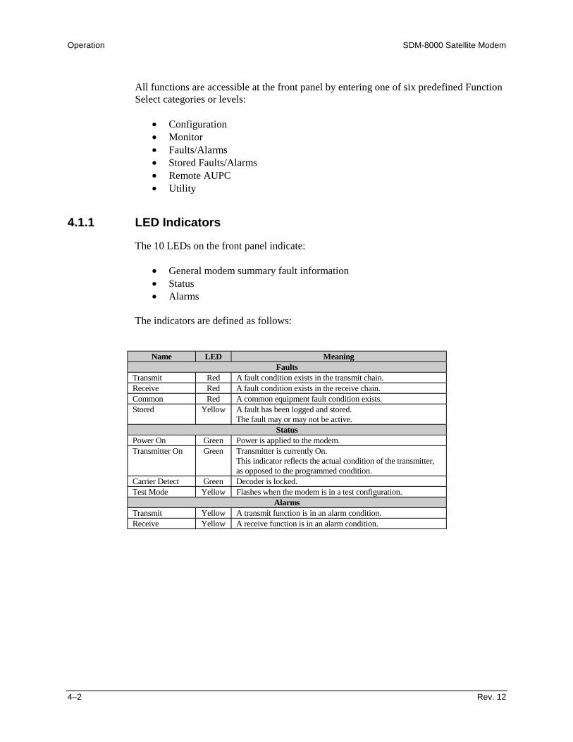
Operation SDM-8000 Satellite Modem
4–2 Rev. 12
All functions are accessible at the front panel by entering one of six predefined FunctionSelect categories or levels:
• Configuration• Monitor• Faults/Alarms• Stored Faults/Alarms• Remote AUPC• Utility
4.1.1 LED Indicators
The 10 LEDs on the front panel indicate:
• General modem summary fault information• Status• Alarms
The indicators are defined as follows:
Name LED MeaningFaults
Transmit Red A fault condition exists in the transmit chain.Receive Red A fault condition exists in the receive chain.Common Red A common equipment fault condition exists.Stored Yellow A fault has been logged and stored.
The fault may or may not be active.Status
Power On Green Power is applied to the modem.Transmitter On Green Transmitter is currently On.
This indicator reflects the actual condition of the transmitter,as opposed to the programmed condition.
Carrier Detect Green Decoder is locked.Test Mode Yellow Flashes when the modem is in a test configuration.
AlarmsTransmit Yellow A transmit function is in an alarm condition.Receive Yellow A receive function is in an alarm condition.

SDM-8000 Satellite Modem Operation
Rev. 12 4–3
4.1.2 Front Panel Keypad
The front panel keypad (Figure 4-2) controls the local operation of the modem. Thekeypad consists of six keys. Each key provides one or more logical functions.
Figure 4-2. Front Panel Keypad
[ENTER] This key is used to select a displayed function or to execute a modem configurationchange.
[CLEAR] This key is used to back out of a selection or to cancel a configuration change whichhas not been executed using [ENTER]. Pressing [CLEAR] generally returns thedisplay to the previous selection.
[←] and [→] These keys are used to move to the next selection or to move the cursor for certainfunctions.
[↑] and [↓] These keys are used primarily to change configuration data (numbers), but are alsoused at times to move from one section to another.
The modem responds by beeping whenever a key is pressed:
• A single beep indicates a valid entry and the appropriate action was taken.
• A double beep indicates an invalid entry or a parameter is not available foroperation.
Operation SDM-8000 Satellite Modem
4–4 Rev. 12
4.2 Menu System
To access and execute all functions, refer to Figures 4-4 through 4-20. Use the mainmenu in Figure 4-3 as a quick reference for accessing the modem functions.
Note: Refer to Chapter 3 for the default settings for IDR, IBS, D&I, Custom, Type X,and System modes.
When the modem power is turned on, the base level of the menu system displays thesign-on message:
• Line 1 of the sign-on message is the modem model number and type• Line 2 is the version number of the firmware
The main level of the menu system is Function Select. To access this base level, pressany of the arrow keys. From the Function Select menu, select one of the functionalcategories:
• Configuration• Monitor• Faults/Alarms• Stored Faults/Alarms• Remote Automatic Uplink Power Control (AUPC)• Utility
Press [←] or [→] to move from one selection to another. When line 2 displays the desiredfunction, select that level by pressing [ENTER]. After entering the appropriate functionallevel, press [←] or [→] to move to the desired function.
To view or change the modem’s configuration, enter the Configuration level from theFunction Select menu. Once in the Configuration menu, press [←] or [→] to scroll throughthe Configuration menu selection:
• Modulator• Demodulator• Interface• Local AUPC• Save• Recall
Press [ENTER] to select the desired Configuration menu option. To view the options forthe selected configuration parameters, press [←] or [→]. To change a configurationparameter, press [ENTER] to begin the change process.
SDM-8000 Satellite Modem Operation
Rev. 12 4–5
Press an arrow key to change the parameters. After the display represents the correctparameters, press [ENTER] to execute the change. This action initiates the necessaryprogramming by the modem.
To return to the Configuration menu, press [CLEAR].
Note: When [CLEAR] is pressed, the modem is configured to the state before CW modewas invoked. The transmitter is automatically turned off to prevent the possible swampingof other channels. To turn the transmitter on, use the IF Output function.
To undo a parameter change prior to execution, press [CLEAR].
The following notes describe each configuration function in detail.
Notes:1. Hardware configuration may change the front panel menu selection. Figures 4-4
through 4-20 list the front panel menu window selections.2. Windows that are specific to certain modem configurations are only accessible
after selecting the appropriate modem configuration. This prevents incompatibleparameters from accidentally being selected.
3. All of the windows are accessible in the Custom mode. Take caution not toselect incompatible parameters, as the modem does not shut out incompatiblecommand choices in the Custom mode.

Operation SDM-8000 Satellite Modem
4–6 Rev. 12
This page is intentionally left blank.
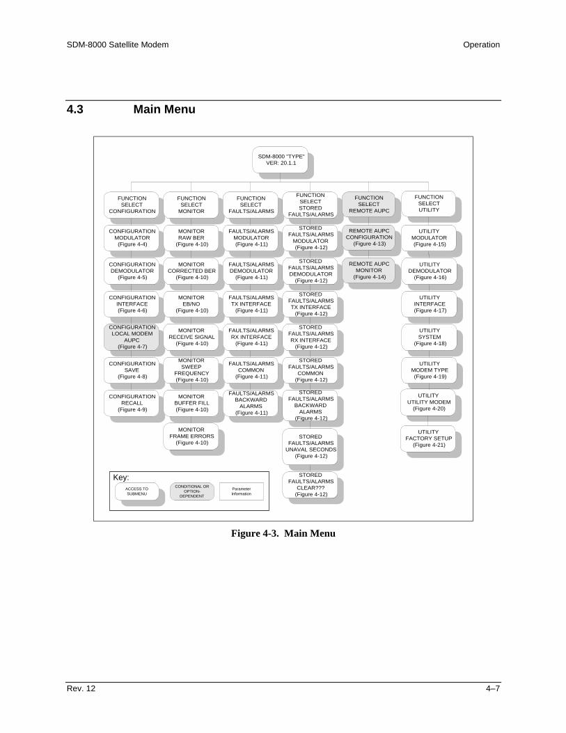
SDM-8000 Satellite Modem Operation
Rev. 12 4–7
4.3 Main Menu
SDM-8000 "TYPE"VER: 20.1.1
FUNCTIONSELECT
CONFIGURATION
FUNCTIONSELECT
MONITOR
FUNCTIONSELECT
FAULTS/ALARMS
CONFIGURATIONMODULATOR
(Figure 4-4)
CONFIGURATIONDEMODULATOR
(Figure 4-5)
CONFIGURATIONLOCAL MODEM
AUPC(Figure 4-7)
CONFIGURATIONINTERFACE(Figure 4-6)
CONFIGURATIONSAVE
(Figure 4-8)
MONITORRAW BER
(Figure 4-10)
MONITORCORRECTED BER
(Figure 4-10)
MONITOREB/NO
(Figure 4-10)
MONITORRECEIVE SIGNAL
(Figure 4-10)
MONITORSWEEP
FREQUENCY(Figure 4-10)
MONITORFRAME ERRORS
(Figure 4-10)
FAULTS/ALARMSMODULATOR(Figure 4-11)
FAULTS/ALARMSDEMODULATOR
(Figure 4-11)
FAULTS/ALARMSTX INTERFACE
(Figure 4-11)
FAULTS/ALARMSRX INTERFACE
(Figure 4-11)
FAULTS/ALARMSCOMMON
(Figure 4-11)
FUNCTIONSELECTSTORED
FAULTS/ALARMS
STOREDFAULTS/ALARMS
MODULATOR(Figure 4-12)
STOREDFAULTS/ALARMSDEMODULATOR
(Figure 4-12)
STOREDFAULTS/ALARMSTX INTERFACE
(Figure 4-12)
STOREDFAULTS/ALARMSRX INTERFACE
(Figure 4-12)
STOREDFAULTS/ALARMS
COMMON(Figure 4-12)
STOREDFAULTS/ALARMS
UNAVAL SECONDS(Figure 4-12)
STOREDFAULTS/ALARMS
CLEAR???(Figure 4-12)
UTILITYINTERFACE(Figure 4-17)
UTILITYSYSTEM
(Figure 4-18)
UTILITYMODEM TYPE(Figure 4-19)
UTILITYUTILITY MODEM
(Figure 4-20)
CONFIGURATIONRECALL
(Figure 4-9)
ACCESS TOSUBMENU
CONDITIONAL OROPTION-
DEPENDENT
ParameterInformation
Key:
FUNCTIONSELECT
REMOTE AUPC
REMOTE AUPCCONFIGURATION
(Figure 4-13)
REMOTE AUPCMONITOR
(Figure 4-14)
FUNCTIONSELECTUTILITY
UTILITYMODULATOR(Figure 4-15)
UTILITYDEMODULATOR
(Figure 4-16)
MONITORBUFFER FILL(Figure 4-10)
FAULTS/ALARMSBACKWARD
ALARMS(Figure 4-11)
STOREDFAULTS/ALARMS
BACKWARDALARMS
(Figure 4-12)
UTILITYFACTORY SETUP
(Figure 4-21)
Figure 4-3. Main Menu
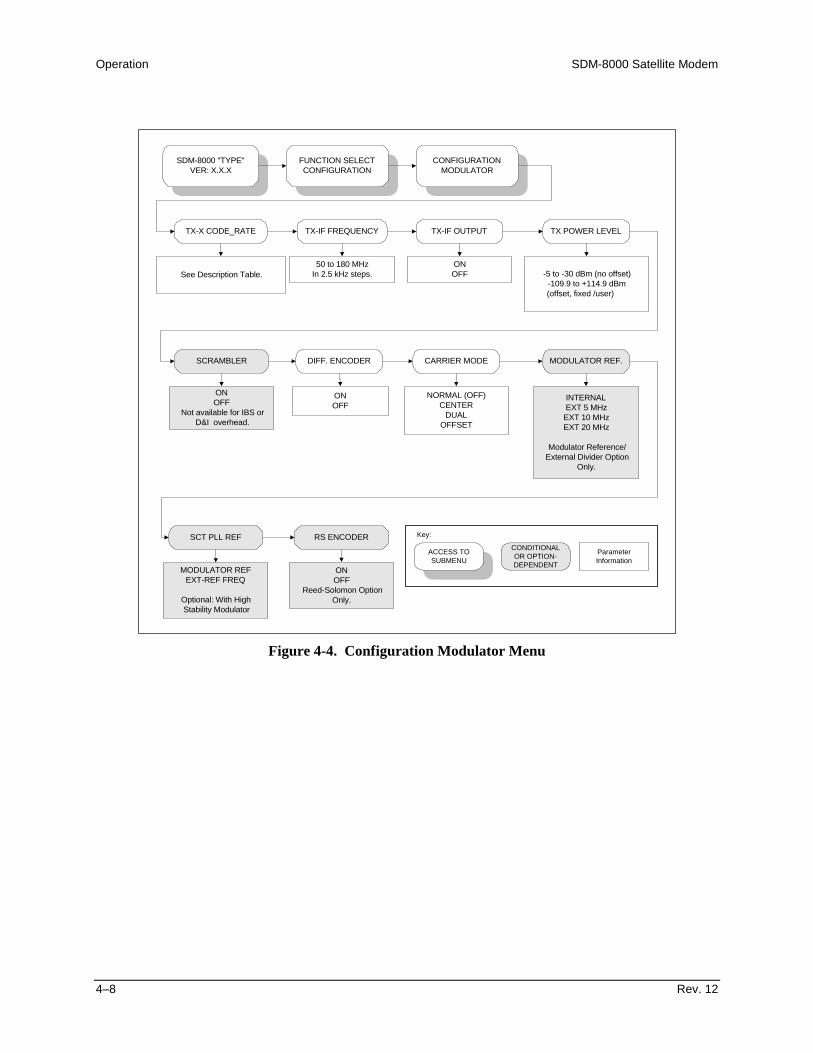
Operation SDM-8000 Satellite Modem
4–8 Rev. 12
SDM-8000 "TYPE"VER: X.X.X
FUNCTION SELECTCONFIGURATION
CONFIGURATIONMODULATOR
TX-X CODE_RATE TX-IF FREQUENCY TX-IF OUTPUT TX POWER LEVEL
SCRAMBLER DIFF. ENCODER CARRIER MODE MODULATOR REF.
RS ENCODER
See Description Table.50 to 180 MHz
In 2.5 kHz steps.ONOFF -5 to -30 dBm (no offset)
-109.9 to +114.9 dBm (offset, fixed /user)
ONOFF
Not available for IBS orD&I overhead.
ONOFF
NORMAL (OFF)CENTER
DUALOFFSET
INTERNALEXT 5 MHzEXT 10 MHzEXT 20 MHz
Modulator Reference/External Divider Option
Only.
ONOFF
Reed-Solomon OptionOnly.
ACCESS TOSUBMENU
CONDITIONALOR OPTION-DEPENDENT
ParameterInformation
Key:SCT PLL REF
MODULATOR REFEXT-REF FREQ
Optional: With HighStability Modulator
Figure 4-4. Configuration Modulator Menu

SDM-8000 Satellite Modem Operation
Rev. 12 4–9
4.3.1 Configuration Modulator
Refer to Figure 4-4.
TX-x CODE_RATE TX-A code_rate/type. Select one of four (A, B, C, or D) predefinedtransmitter code/data rate combinations or a variable rate selection (V).
Viterbi SequentialCode Rate Data Rate Range Data Rate RangeBPSK 1/2 9.6 to 3150.OK 9.6 to 1544.0KQPSK 1/2 19.0 to 6300.0K 19.0 to 2185.0KQPSK 3/4 28.5 to 9312.0K 28.5 to 3277.0KQPSK 7/8 33.25 to 9312.0K 33.25 to 3823.0K8PSK 2/3 38.0 to 9312.0K Not Applicable8PSK 5/6 47.5 to 9312.0K Not Applicable16QAM 3/4 57.0 to 9312.0K Not Applicable16QAM 7/8 64.0 to 9312.0K Not ApplicableQPSK 1/1 38.0 to 9312.0K Not Applicable
On entry, the current transmitter rate is displayed with the flashing cursor onthe first character of the code rate on line 1. Line 2 displays the data rate.Press [←] or [→] to make the selection. To select the currently definedvariable data rate, select TX-V, and press [ENTER] twice.
To change the rate using the variable rate selection, press [ENTER] whenTX-V is displayed. A flashing cursor is displayed on the first character of thecoding type on line 1. Press [←] or [→] to move the flashing cursor, and [↑]or [↓] to increment or decrement the digit at the flashing cursor. Press[ENTER] to execute the change.
Notes:1. When the TX rate has been programmed, the transmitter is
automatically turned off to prevent swamping of other channels. Toturn on the transmitter, use the IF Output function.
2. When using the Reed-Solomon option, the TX data program alsoturns off the Reed-Solomon encoder. This allows theReed-Solomon Codec and the non-Reed-Solomon Codec modemsto operate together in a switch rack system.
TX_IF FREQUENCY Programs the modulator transmit frequency between 50 and 180 MHz, inmultiples of 2.5 kHz steps.
On entry, the current transmitter frequency is displayed with the flashingcursor on the first character. Press [←] or [→] to move the flashing cursor,and [↑] or [↓] to increment or decrement the digit at the flashing cursor.Press [ENTER] to execute the change.
Note: When the transmitter frequency is changed, the transmitter isautomatically turned off to prevent the possible swamping of other channels.To turn the transmitter on, use the IF Output function. When using the Reed-Solomon option, the frequency change also turns off the Reed-Solomonencoder. This allows the Reed-Solomon Codec/non-Reed-Solomon Codecmodems to operate together in a switch rack system.
TX-IF OUTPUT Programs the modulator output On or Off.
On entry, the current status of the output is displayed. Press an arrow key tomake the selection. Press [ENTER] to execute the change.

Operation SDM-8000 Satellite Modem
4–10 Rev. 12
TX POWER LEVEL Programs the modulator output power level from:
• -5 dBm to -30 dBm for no offset•-109.9 dBm to -114.9 dBm for offset, fixed user
Notes:1. The front panel display may be changed in the power offset utility.
Using that function does not change the actual output power level.2. An offset can be added through the Utility menu to remove loses or
gains in the system.
On entry, the current transmitter power level is displayed with the flashingcursor on the first character. Press [↑] or [↓] to increase or decrease theoutput power level in 0.1 dBm steps. Press [ENTER] to execute the change.
The high power oscillator option is +5 dB to -20 dB. The window displaysAUPC_PWR when the AUPC is turned on in the AUPC Configurationmenu. For more information, refer to Section 4.2.10.1.
SCRAMBLER Programs the scrambler On or Off.
On entry, the current status of the V.35 scrambler is displayed. Press anarrow key to make the selection. Press [ENTER] to execute the change.
Note: This menu is not available for IBS or D&I, and will not appear in thefront panel menu. When using the Reed-Solomon option, the TX IDRoverhead program automatically controls the V.35 scrambler (if theReed-Solomon encoder is set to Off) or the synchronous scrambler (if Reed-Solomon encoder is set to On).
DIFF. ENCODER Programs the differential encoder On or Off.
On entry, the current status of the differential encoder is displayed. Press anarrow key to make the selection. Press [ENTER] to execute the change.
CARRIER MODE Programs the modem for continuous wave mode. Four modes of operationare available:
• Normal (Off): The Carrier mode is normally in the Off position.To execute any of the Carrier continuous wave modes, enter theCarrier mode and select the test mode of choice.
• Center: Generates a carrier at the current modulator frequency. Thiscan be used to measure the output frequency.
• Dual: Generates a dual side-band suppressed carrier signal. Side-bands are at one-half of the symbol rate from the carrier. This isused to check the channel balance and carrier null.
• Offset: Generates a single upper side-band suppressed carriersignal. The upper side-band is at one-quarter of the symbol ratefrom the carrier. This is used to check the quadrature.
On entry, the Center mode is displayed. To activate this test mode, press[ENTER]. Press an arrow key to select the desired mode.

SDM-8000 Satellite Modem Operation
Rev. 12 4–11
MODULATOR REF. Optional program for selecting the following references:
• High stability 5 MHz internal reference• 5 MHz, 10 MHz, and 20 MHz external references
On entry, the Internal mode is displayed. Press [↑] or [↓] to make theselection. Press [ENTER] to execute the change.
Optional: High Stability ModulatorSCT PLL REF Optional program for selecting the following references:
• Modulator REF• EXT-REF Frequency
On entry, the current status is displayed. Press [↑] or [↓] to make theselection. Press [ENTER] to execute the change.
Optional: High Stability ModulatorRS ENCODER Programs the Reed-Solomon encoder On or Off.
On entry, the current status of the Reed-Solomon encoder is displayed. Pressan arrow key to make the selection. Press [ENTER] to execute the change.
Notes:1. Programming the Reed-Solomon encoder automatically turns off
the RF transmitter (because of symbol rate changes). If none of theproper overhead types and data rates apply, the Reed-Solomonencoder program in the on state will be rejected (double beep).
2. Programming the TX data rate or TX frequency automaticallyturns off the Reed-Solomon encoder. This allows theReed-Solomon Codec and the non-Reed-Solomon modems tooperate together in a switch rack system.

Operation SDM-8000 Satellite Modem
4–12 Rev. 12
SDM-8000 "TYPE"VER: X.X.X
FUNCTION SELECTCONFIGURATION
CONFIGURATIONDEMODULATOR
RX-X CODE_RATE RX-IF FREQUENCY DESCRAMBLER DIFF. DECODER
RF LOOP BACK IF LOOP BACK BER THRESHOLD SWEEP CENTER
SWEEP RANGE
50 to 180 MHz
(in 2.5 kHz steps)
ONOFF
Not available for IBS andD&I
ONOFF
ONOFF
ONOFF
1.0 E-3 to 1.0 E-8NONE -30000 Hz to +30000 Hz
0 Hz to 60000 Hz
REACQUISITION
0 to 999 SECONDS
RS DECODER
ONCORRECTION_OFF
OFFReed-Solomon option only.
ACCESS TOSUBMENU
CONDITIONAL OROPTION-DEPENDENT
ParameterInformation
Key:
See Description Table.
Figure 4-5. Configuration Demodulator Menu

SDM-8000 Satellite Modem Operation
Rev. 12 4–13
4.3.2 Configuration Demodulator
Refer to Figure 4-5.
RX-x CODE_RATE/TYPE Receiver rate selection. Select one of four (A, B, C, or D) predefined receiverdecoder/data rate combinations) or a variable rate selection (V).
Viterbi SequentialCode Rate Data Rate Range Data Rate RangeBPSK 1/2 9.6 to 3150.OK 9.6 to 1544.0KQPSK 1/2 19.0 to 6300.0K 19.0 to 2185.0KQPSK 3/4 28.5 to 9312.0K 28.5 to 3277.0KQPSK 7/8 33.25 to 9312.0K 33.25 to 3823.0K8PSK 2/3 38.0 to 9312.0K Not Applicable8PSK 5/6 47.5 to 9312.0K Not Applicable16QAM 3/4 57.0 to 9312.0K Not Applicable16QAM 7/8 64.0 to 9312.0K Not ApplicableQPSK 1/1 38.0 to 9312.0K Not Applicable
On entry, the current receiver rate is displayed with the flashing cursor on the firstcharacter of the code rate on line 1. The data rate is displayed on line 2. Press anarrow key to select one of four pre-defined rates (A, B, C, or D). To select thecurrently defined variable data rate, select RX-V, and press [ENTER] twice.
To change the rate using the variable rate selection, press [ENTER] when RX-V isdisplayed. A flashing cursor is displayed on the first character of the coding type online 1. Press [←] or [→] to move the flashing cursor, and [↑] or [↓] to increment ordecrement the digit at the flashing cursor. Press [ENTER] to execute the change.
Note: When using the Reed-Solomon option, the RX data rate programautomatically turns off the Reed-Solomon decoder. This allows the Reed-SolomonCodec and the non-Reed-Solomon Codec modems to operate together in a switchrack system.
RX-IF FREQUENCY Programs the demodulator receive frequency between 50 and 180 MHz, in 2.5 kHzsteps.
On entry, the current receive frequency is displayed with the flashing cursor on thefirst character. Press [←] or [→] to move the flashing cursor, and [↑] or [↓] toincrement or decrement the digit at the flashing cursor. Press [ENTER] to executethe change.
Note: When using the Reed-Solomon option, the RX frequency programautomatically turns off the Reed-Solomon decoder. This allows the Reed-SolomonCodec and the non-Reed-Solomon Codec modems to operate together in a switchrack system.
DESCRAMBLER Programs the V.35 descrambler On or Off.
On entry, the current status of the synchronous descrambler is displayed. Press anarrow key to make the selection. Press [ENTER] to execute the change.
Note: This window is not available for IBS or D&I, and will not appear in the frontpanel menu. When using the Reed-Solomon option, the RX IDR overhead programautomatically controls the V.35 descrambler (if the Reed-Solomon decoder is set toOff or Correction Off) or the synchronous descrambler (if the Reed-Solomondecoder is set to On).
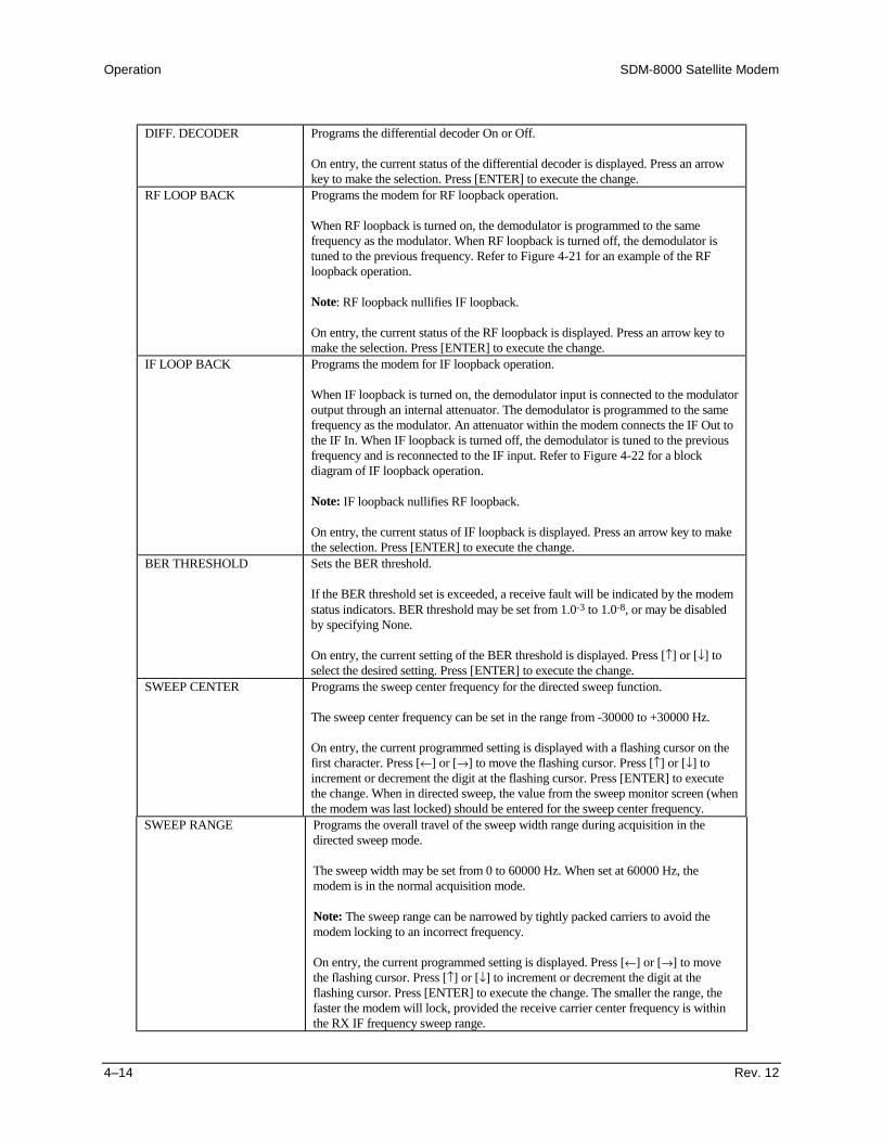
Operation SDM-8000 Satellite Modem
4–14 Rev. 12
DIFF. DECODER Programs the differential decoder On or Off.
On entry, the current status of the differential decoder is displayed. Press an arrowkey to make the selection. Press [ENTER] to execute the change.
RF LOOP BACK Programs the modem for RF loopback operation.
When RF loopback is turned on, the demodulator is programmed to the samefrequency as the modulator. When RF loopback is turned off, the demodulator istuned to the previous frequency. Refer to Figure 4-21 for an example of the RFloopback operation.
Note: RF loopback nullifies IF loopback.
On entry, the current status of the RF loopback is displayed. Press an arrow key tomake the selection. Press [ENTER] to execute the change.
IF LOOP BACK Programs the modem for IF loopback operation.
When IF loopback is turned on, the demodulator input is connected to the modulatoroutput through an internal attenuator. The demodulator is programmed to the samefrequency as the modulator. An attenuator within the modem connects the IF Out tothe IF In. When IF loopback is turned off, the demodulator is tuned to the previousfrequency and is reconnected to the IF input. Refer to Figure 4-22 for a blockdiagram of IF loopback operation.
Note: IF loopback nullifies RF loopback.
On entry, the current status of IF loopback is displayed. Press an arrow key to makethe selection. Press [ENTER] to execute the change.
BER THRESHOLD Sets the BER threshold.
If the BER threshold set is exceeded, a receive fault will be indicated by the modemstatus indicators. BER threshold may be set from 1.0-3 to 1.0-8, or may be disabledby specifying None.
On entry, the current setting of the BER threshold is displayed. Press [↑] or [↓] toselect the desired setting. Press [ENTER] to execute the change.
SWEEP CENTER Programs the sweep center frequency for the directed sweep function.
The sweep center frequency can be set in the range from -30000 to +30000 Hz.
On entry, the current programmed setting is displayed with a flashing cursor on thefirst character. Press [←] or [→] to move the flashing cursor. Press [↑] or [↓] toincrement or decrement the digit at the flashing cursor. Press [ENTER] to executethe change. When in directed sweep, the value from the sweep monitor screen (whenthe modem was last locked) should be entered for the sweep center frequency.
SWEEP RANGE Programs the overall travel of the sweep width range during acquisition in thedirected sweep mode.
The sweep width may be set from 0 to 60000 Hz. When set at 60000 Hz, themodem is in the normal acquisition mode.
Note: The sweep range can be narrowed by tightly packed carriers to avoid themodem locking to an incorrect frequency.
On entry, the current programmed setting is displayed. Press [←] or [→] to movethe flashing cursor. Press [↑] or [↓] to increment or decrement the digit at theflashing cursor. Press [ENTER] to execute the change. The smaller the range, thefaster the modem will lock, provided the receive carrier center frequency is withinthe RX IF frequency sweep range.
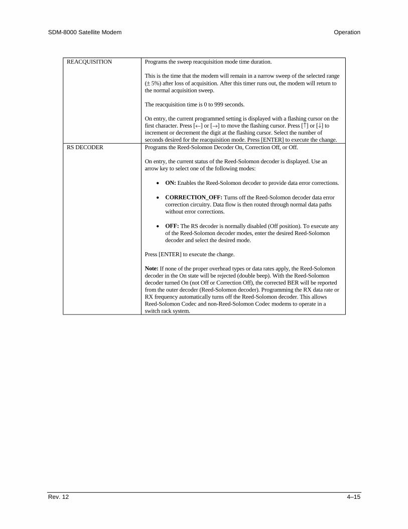
SDM-8000 Satellite Modem Operation
Rev. 12 4–15
REACQUISITION Programs the sweep reacquisition mode time duration.
This is the time that the modem will remain in a narrow sweep of the selected range(± 5%) after loss of acquisition. After this timer runs out, the modem will return tothe normal acquisition sweep.
The reacquisition time is 0 to 999 seconds.
On entry, the current programmed setting is displayed with a flashing cursor on thefirst character. Press [←] or [→] to move the flashing cursor. Press [↑] or [↓] toincrement or decrement the digit at the flashing cursor. Select the number ofseconds desired for the reacquisition mode. Press [ENTER] to execute the change.
RS DECODER Programs the Reed-Solomon Decoder On, Correction Off, or Off.
On entry, the current status of the Reed-Solomon decoder is displayed. Use anarrow key to select one of the following modes:
• ON: Enables the Reed-Solomon decoder to provide data error corrections.
• CORRECTION_OFF: Turns off the Reed-Solomon decoder data errorcorrection circuitry. Data flow is then routed through normal data pathswithout error corrections.
• OFF: The RS decoder is normally disabled (Off position). To execute anyof the Reed-Solomon decoder modes, enter the desired Reed-Solomondecoder and select the desired mode.
Press [ENTER] to execute the change.
Note: If none of the proper overhead types or data rates apply, the Reed-Solomondecoder in the On state will be rejected (double beep). With the Reed-Solomondecoder turned On (not Off or Correction Off), the corrected BER will be reportedfrom the outer decoder (Reed-Solomon decoder). Programming the RX data rate orRX frequency automatically turns off the Reed-Solomon decoder. This allowsReed-Solomon Codec and non-Reed-Solomon Codec modems to operate in aswitch rack system.
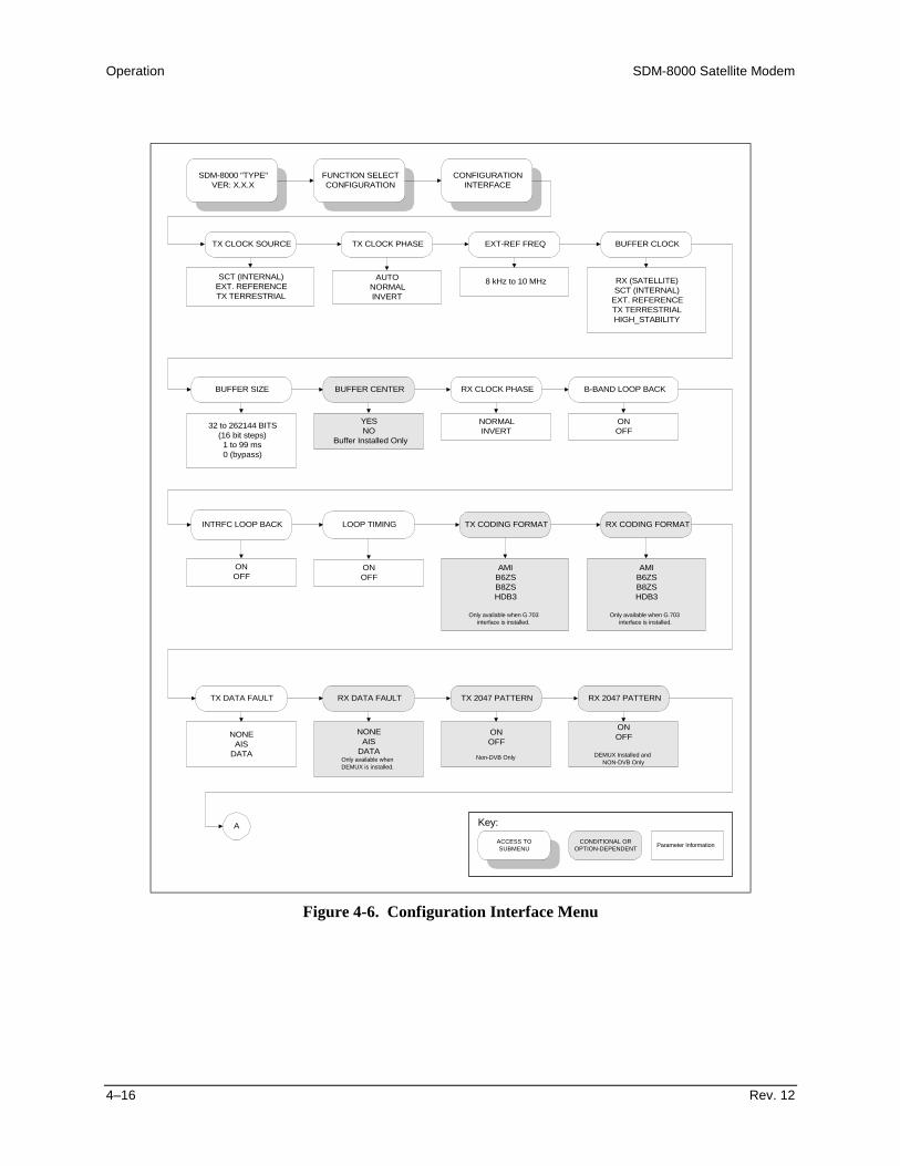
Operation SDM-8000 Satellite Modem
4–16 Rev. 12
SDM-8000 "TYPE"VER: X.X.X
FUNCTION SELECTCONFIGURATION
CONFIGURATIONINTERFACE
TX CLOCK SOURCE TX CLOCK PHASE EXT-REF FREQ BUFFER CLOCK
BUFFER SIZE BUFFER CENTER RX CLOCK PHASE B-BAND LOOP BACK
INTRFC LOOP BACK LOOP TIMING
SCT (INTERNAL)EXT. REFERENCETX TERRESTRIAL
AUTONORMALINVERT
8 kHz to 10 MHz RX (SATELLITE)SCT (INTERNAL)
EXT. REFERENCETX TERRESTRIALHIGH_STABILITY
32 to 262144 BITS(16 bit steps)
1 to 99 ms0 (bypass)
YESNO
Buffer Installed Only
NORMALINVERT
ONOFF
ONOFF
ONOFF
TX CODING FORMAT
AMIB6ZSB8ZSHDB3
Only available when G.703interface is installed.
RX CODING FORMAT
AMIB6ZSB8ZSHDB3
Only available when G.703 interface is installed.
TX DATA FAULT RX DATA FAULT
NONEAIS
DATA
NONEAIS
DATAOnly available whenDEMUX is installed.
TX 2047 PATTERN
ONOFF
Non-DVB Only
RX 2047 PATTERN
ONOFF
DEMUX Installed andNON-DVB Only
A
ACCESS TOSUBMENU
CONDITIONAL OROPTION-DEPENDENT Parameter Information
Key:
Figure 4-6. Configuration Interface Menu

SDM-8000 Satellite Modem Operation
Rev. 12 4–17
IBS SCRAMBLER IBS DESCRAMBLER
ONOFF
IBS or D&I overhead only.
ONOFF
IBS or D&I overhead only.
SERVICE CHANNELADJUST
CHANNEL: TX-1CHANNEL: TX-2CHANNEL: RX-1CHANNEL: RX-2
Level = +10 to -20 dBm.IDR only.
DROP FORMAT
E1_CCSE1_CASE1_IBS
E1_31_TST1
T1_IBST1_ESF
T1_ESF_ST1_S
D&I only.
A
INSERT FORMAT DROP CHANNELASSIGNMENTS
E1_CCSE1_CASE1_IBS
E1_31_TST1
T1_IBST1_ESF
T1_ESF_ST1_S
D&I only.
DROP SATT-SLOT TERR
D&I only.
INSERT CHANNELASSIGNMENTS
INSERT SATT-SLOT TERR
D&I only.
ASYNC TX BAUD
BAUD RATES (bps) 110 2400 150 4800 300 9600 600 19200 1200 38400
ASYNC overhead only.
ASYNC RX BAUD ASYNC TX LENGTH
BAUD RATES (bps) 110 2400 150 4800 300 9600 600 19200 1200 38400
ASYNC overhead only.
5 BITS6 BITS7 BITS8 BITS
ASYNC overhead only.
ASYNC RX LENGTH
5 BITS6 BITS7 BITS8 BITS
ASYNC overhead only.
ASYNC TX STOP
1 BITS2 BITS
ASYNC overhead only.
ASYNC RX STOP ASYNC TX PARITY
1 BITS2 BITS
ASYNC overhead only.
EVENODD
NONEASYNC overhead only.
CONFIGURATIONINTERFACE continued
ACCESS TOSUBMENU
CONDITIONAL OROPTION-DEPENDENT Parameter Information
Key:
ASYNC RX PARITY TX DVB FRAMING
188204
NONEDVB overhead only.
EVENODD
NONEASYNC overhead only.
RX DVB FRAMING
188204
NONEDVB overhead only.
Figure 4-6. Configuration Interface Menu (Continued)

Operation SDM-8000 Satellite Modem
4–18 Rev. 12
4.3.3 Configuration Interface
Refer to Figure 4-6.
TX CLOCK SOURCE Programs the clock source for the modem transmitter clock to the followingconfigurations:
• SCT (Internal): Sets the TX clock to operate from the modem internal clock(this is also the fallback clock). The SCT can be locked to a high stabilitysource depending on the setting for modulator reference.
• External Reference: Sets the TX clock to operate from the external referenceclock at the Data I/O connector. Transmit Clock source must bephase/frequency locked to the data that is being transmitted.
• TX Terrestrial: Sets the TX clock to recover timing from the incomingclock/data.
On entry, the current transmit clock setting is displayed. Press an arrow key to makethe selection. Press [ENTER] to execute the change.
TX CLOCK PHASE Programs the TX clock phase to Auto, Normal, or Invert.
On entry, the current setting of the TX clock phase is displayed. Press [↑] or [↓] tomake the selection. When Auto is selected, the modem will automatically selectNormal or Invert to properly phase the TX clock with the TX data. Press [ENTER] toexecute the change.
EXT-REF FREQ Programs the external reference clock input frequency between 8 kHz and 10 MHz.This is the EXT Clock input at the Data I/O connector.
Note: The clock rate must be an integer multiple of the data rate. The integer must bebetween 3 and 214 -1.
This clock source is typically programmed to:
• 1544 kHz• 5000 kHz• 10000 kHz.
On entry, the current setting for the external reference is displayed. Press [←] or [→] toincrement or decrement the digit at the flashing cursor. Press [ENTER] to execute thechange.
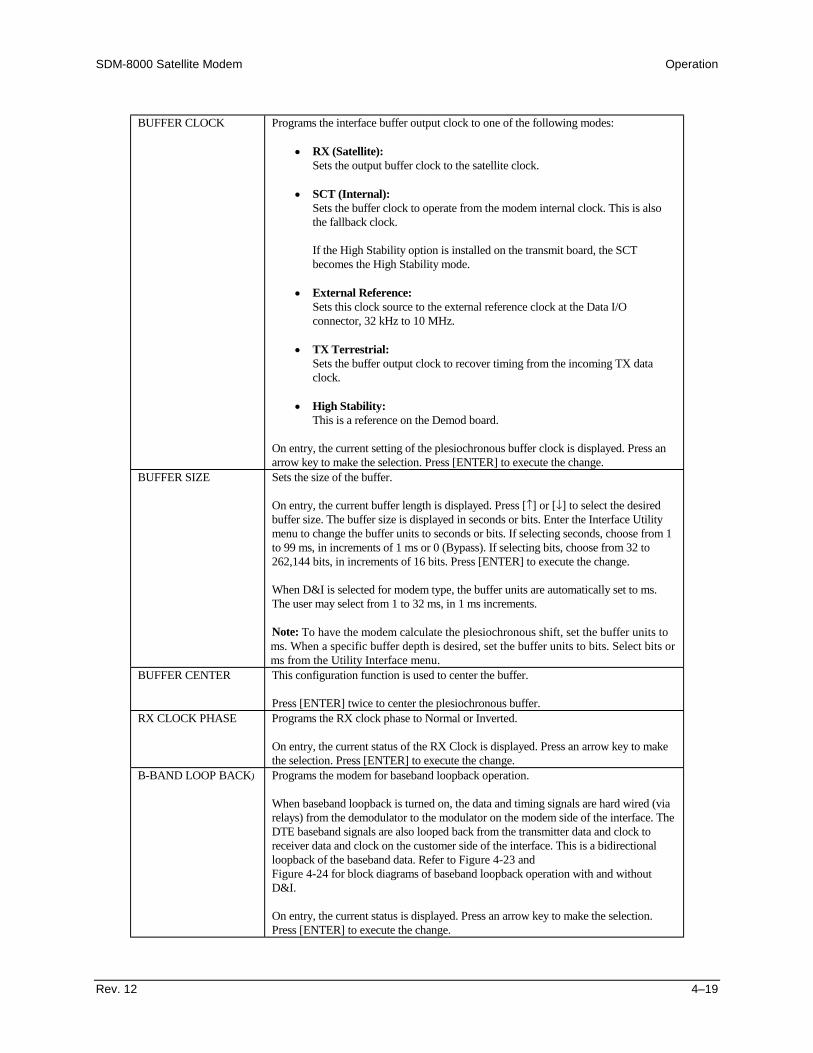
SDM-8000 Satellite Modem Operation
Rev. 12 4–19
BUFFER CLOCK Programs the interface buffer output clock to one of the following modes:
• RX (Satellite):Sets the output buffer clock to the satellite clock.
• SCT (Internal):Sets the buffer clock to operate from the modem internal clock. This is alsothe fallback clock.
If the High Stability option is installed on the transmit board, the SCTbecomes the High Stability mode.
• External Reference:Sets this clock source to the external reference clock at the Data I/Oconnector, 32 kHz to 10 MHz.
• TX Terrestrial:Sets the buffer output clock to recover timing from the incoming TX dataclock.
• High Stability:This is a reference on the Demod board.
On entry, the current setting of the plesiochronous buffer clock is displayed. Press anarrow key to make the selection. Press [ENTER] to execute the change.
BUFFER SIZE Sets the size of the buffer.
On entry, the current buffer length is displayed. Press [↑] or [↓] to select the desiredbuffer size. The buffer size is displayed in seconds or bits. Enter the Interface Utilitymenu to change the buffer units to seconds or bits. If selecting seconds, choose from 1to 99 ms, in increments of 1 ms or 0 (Bypass). If selecting bits, choose from 32 to262,144 bits, in increments of 16 bits. Press [ENTER] to execute the change.
When D&I is selected for modem type, the buffer units are automatically set to ms.The user may select from 1 to 32 ms, in 1 ms increments.
Note: To have the modem calculate the plesiochronous shift, set the buffer units toms. When a specific buffer depth is desired, set the buffer units to bits. Select bits orms from the Utility Interface menu.
BUFFER CENTER This configuration function is used to center the buffer.
Press [ENTER] twice to center the plesiochronous buffer.RX CLOCK PHASE Programs the RX clock phase to Normal or Inverted.
On entry, the current status of the RX Clock is displayed. Press an arrow key to makethe selection. Press [ENTER] to execute the change.
B-BAND LOOP BACK) Programs the modem for baseband loopback operation.
When baseband loopback is turned on, the data and timing signals are hard wired (viarelays) from the demodulator to the modulator on the modem side of the interface. TheDTE baseband signals are also looped back from the transmitter data and clock toreceiver data and clock on the customer side of the interface. This is a bidirectionalloopback of the baseband data. Refer to Figure 4-23 andFigure 4-24 for block diagrams of baseband loopback operation with and withoutD&I.
On entry, the current status is displayed. Press an arrow key to make the selection.Press [ENTER] to execute the change.

Operation SDM-8000 Satellite Modem
4–20 Rev. 12
INTRFC LOOP BACK Programs the modem for interface loopback operation.
When interface loopback is turned on, data is looped back at the modem side of theinterface. This is a bidirectional loopback of the data after the baseband data has hadthe overhead added. Refer to Figure 4-25 for a block diagram of interface loopbackoperation.
On entry, the current status is displayed. Press an arrow key to make the selection.Press [ENTER] to execute the change.
LOOP TIMING Programs the modem SCT output clock to be phased locked to the RX satellite clock.The SCT (INTERNAL) will change to SCT (LOOP) when turned ON.
Note: When the modem has been configured for ASLT, the SCT output will be thesame rate as the modems TX data rate, but still phased locked to the unbalanced RXsatellite data rate.
On entry, the current status is displayed. Press an arrow key to make the selection.Press [ENTER] to execute the change.
TX CODING FORMAT Programs the transmitter for AMI, B6ZS, B8ZS, or HDB3 coding of the basebanddata.
On entry, the current coding format is displayed. Press an arrow key to make theselection. Press [ENTER] to execute the change.
Note: This menu is only available when G.703 interface is installed.RX CODING FORMAT Programs the receiver for AMI, B6ZS, B8ZS, or HDB3 coding.
On entry, the current coding format is displayed. Press an arrow key to make theselection. Press [ENTER] to execute the change.
Note: This menu is only available when G.703 interface is installed.TX DATA FAULT Transmit data fault. Press an arrow key to select one of the following modes:
• None: The transmit interface fault Data/AIS is not activated.
• Data: Sets transmit interface fault Data/AIS to monitor a fault condition of all1s or 0s. This is referred to as a data-stable condition, which means that thedata is not transitioning.
• Alarm Indication Signal (AIS): Sets transmit interface fault Data/AIS tomonitor a fault condition of all 1s from customer data input to the modem.
On entry, the current TX data fault that is being monitored is displayed. Press an arrowkey to make the selection. Press [ENTER] to execute the change.
Note: This menu is only available when the MUX is installed.RX DATA FAULT Receive data fault. Selects a receive interface fault monitor of None, AIS, or Data.
The data monitored for RX data is coming from the satellite. Refer to TX DATAFAULT for a description of function choices.
On entry, the current RX DATA FAULT that is being monitored is displayed. Press anarrow key to make the selection. Press [ENTER] to execute the change.
*Note: This menu is only available when the DEMUX is installed.

SDM-8000 Satellite Modem Operation
Rev. 12 4–21
TX 2047 PATTERN Programs the transmitter to On or Off to insert a 2047 pattern in place of the normaltransmit data.
On entry, the current status is displayed. Press an arrow key to make the selection.Press [ENTER] to execute the change.
*Note: This menu is only available when the MUX is installed.RX 2047 PATTERN) Programs the modem to receive a 2047 pattern as the normal receive data and allows
the BER monitor to work on that 2047 pattern.
On entry, the current status is displayed. Press an arrow key to select On or Off. Press[ENTER] to execute the change.
*Note: This menu is only available when the DEMUX is installed.
*Note: The Mux and Demux are located in Field Programmable gate array chips on the interfacePCB. U53 is the Demux chip and U52 is the Mux chip.
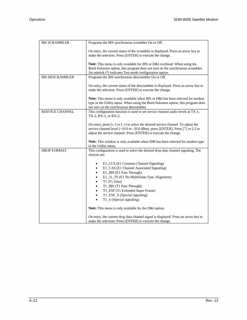
Operation SDM-8000 Satellite Modem
4–22 Rev. 12
IBS SCRAMBLER Programs the IBS synchronous scrambler On or Off.
On entry, the current status of the scrambler is displayed. Press an arrow key tomake the selection. Press [ENTER] to execute the change.
Note: This menu is only available for IBS or D&I overhead. When using theReed-Solomon option, this program does not turn on the synchronous scrambler.An asterisk (*) indicates Test mode configuration option.
IBS DESCRAMBLER Programs the IBS synchronous descrambler On or Off.
On entry, the current status of the descrambler is displayed. Press an arrow key tomake the selection. Press [ENTER] to execute the change.
Note: This menu is only available when IBS or D&I has been selected for modemtype in the Utility menu. When using the Reed-Solomon option, this program doesnot turn on the synchronous descrambler.
SERVICE CHANNEL This configuration function is used to set service channel audio levels at TX-1,TX-2, RX-1, or RX-2.
On entry, press [←] or [→] to select the desired service channel. To adjust theservice channel level (+10.0 to -20.0 dBm), press [ENTER]. Press [↑] or [↓] toadjust the service channel. Press [ENTER] to execute the change.
Note: This window is only available when IDR has been selected for modem typein the Utility menu.
DROP FORMAT This configuration is used to select the desired drop data channel signaling. Thechoices are:
• E1_CCS (E1 Common Channel Signaling)• E1_CAS (E1 Channel Associated Signaling)• E1_IBS (E1 Pass Through)• E1_31_TS (E1 No Multiframe Sync Alignment)• T1 (T1 Data)• T1_IBS (T1 Pass Through)• T1_ESF (T1 Extended Super Frame)• T1_ESF_S (Special signaling)• T1_S (Special signaling)
Note: This menu is only available for the D&I option.
On entry, the current drop data channel signal is displayed. Press an arrow key tomake the selection. Press [ENTER] to execute the change.

SDM-8000 Satellite Modem Operation
Rev. 12 4–23
INSERT FORMAT Selects the desired insert data channel signaling. The choices are:
• E1_CCS (E1 Common Channel Signaling)• E1_CAS (E1 Channel Associated Signaling)• E1_IBS (E1 Pass Through)• E1_31_TS (E1 No Multiframe Sync Alignment)• T1 (T1 Data Signal)• T1_IBS (T1 Pass Through)• T1_ESF (T1 Extended Super Frame)• T1_ESF_S (Special signaling)• T1_S (Special signaling)
Note: This menu is only available for the D&I option.
On entry, the current insert data channel signal is displayed. Press an arrow key tomake the selection. Press [ENTER] to execute the change.
DROP CHANNELASSIGNMENTS
Programs the drop channels into the following desired time slot:
• Channels 1 to 31: E1_CCS, E1_31_TS, and E1_CAS• Channels 1 to 24: T1, T1_ESF, T1_S, and T1_ESF_S
Note: Dropping time slot 0 is not allowed for E1_CCS, E1_CAS, or E1_31_TS.Use time slot 16 only in E1_31_TS. The number of drop channels is data ratedependent. The number of drop channels is DR/64 kbit/s. Thus, when the data rateis 64 kbit/s, there is only one drop channel. When the data rate is 1920 kbit/s, thereare 30 drop channels.
On entry, drop channel 1 and the current time slot are displayed. Press [↑] or [↓] toselect the drop channel to be programmed.
Press [ENTER] to begin programming. Press [↑] or [↓] to select the time slot foreach available drop channel by incrementing or decrementing the digit at theflashing cursor. Press [ENTER] to execute the change.
INSERT CHANNELASSIGNMENTS
Programs the satellite channels into the following desired terrestrial frame slot:
• Channels 1 to 31: E1_CCS, E1_31_TS, and E1_CAS• Channels 1 to 24: T1, T1_ESF, T1_S, and T1_ESF_S
Note: The number of satellite channels is data rate dependent. The number ofchannels is DR/64 kbit/s. When the satellite data rate is 64 kbit/s, there is only onesatellite channel. When the satellite data rate is 1920 kbit/s, there are 30 satellitechannels.
On entry, satellite channel 1 and the current terrestrial frame slot are displayed.Press [↑] or [↓] to select the satellite channel to be programmed. Press [ENTER] tochoose the satellite channel to be programmed. Press [↑] or [↓] to select theterrestrial frame slot for each available satellite channel by incrementing ordecrementing the digit at the flashing cursor. If a time slot is unused, select NI (NotInserted). Press [ENTER] to execute the change.
Note: This menu is only available for the D&I option.ASYNC TX BAUD Programs the ASYNC overhead transmit baud rate.
On entry, the current status of the ASYNC TX baud rate is displayed. Press anarrow key to select one of the following baud rates (bit/s): 110, 150, 300, 600,1200, 2400, 4800, 9600, 19200, 38400.
Press [ENTER] to execute the change.
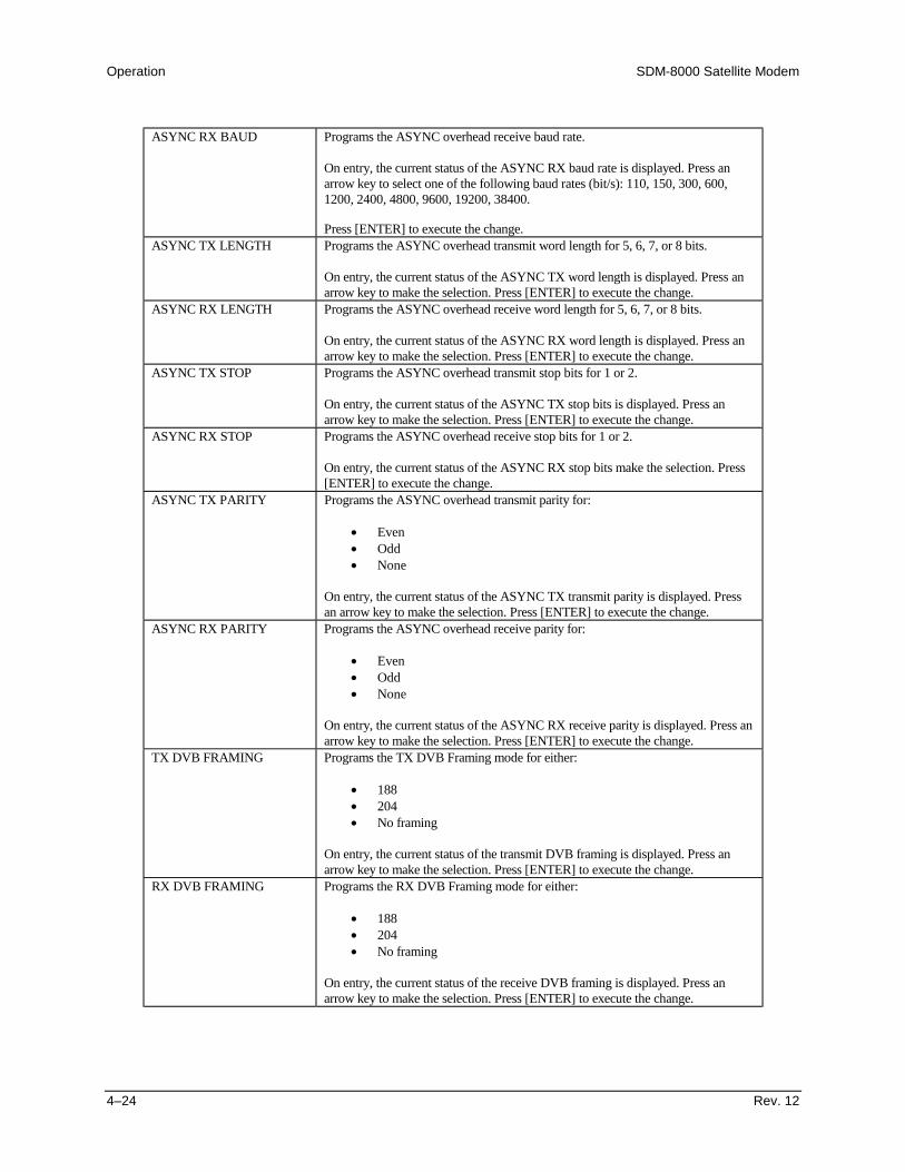
Operation SDM-8000 Satellite Modem
4–24 Rev. 12
ASYNC RX BAUD Programs the ASYNC overhead receive baud rate.
On entry, the current status of the ASYNC RX baud rate is displayed. Press anarrow key to select one of the following baud rates (bit/s): 110, 150, 300, 600,1200, 2400, 4800, 9600, 19200, 38400.
Press [ENTER] to execute the change.ASYNC TX LENGTH Programs the ASYNC overhead transmit word length for 5, 6, 7, or 8 bits.
On entry, the current status of the ASYNC TX word length is displayed. Press anarrow key to make the selection. Press [ENTER] to execute the change.
ASYNC RX LENGTH Programs the ASYNC overhead receive word length for 5, 6, 7, or 8 bits.
On entry, the current status of the ASYNC RX word length is displayed. Press anarrow key to make the selection. Press [ENTER] to execute the change.
ASYNC TX STOP Programs the ASYNC overhead transmit stop bits for 1 or 2.
On entry, the current status of the ASYNC TX stop bits is displayed. Press anarrow key to make the selection. Press [ENTER] to execute the change.
ASYNC RX STOP Programs the ASYNC overhead receive stop bits for 1 or 2.
On entry, the current status of the ASYNC RX stop bits make the selection. Press[ENTER] to execute the change.
ASYNC TX PARITY Programs the ASYNC overhead transmit parity for:
• Even• Odd• None
On entry, the current status of the ASYNC TX transmit parity is displayed. Pressan arrow key to make the selection. Press [ENTER] to execute the change.
ASYNC RX PARITY Programs the ASYNC overhead receive parity for:
• Even• Odd• None
On entry, the current status of the ASYNC RX receive parity is displayed. Press anarrow key to make the selection. Press [ENTER] to execute the change.
TX DVB FRAMING Programs the TX DVB Framing mode for either:
• 188• 204• No framing
On entry, the current status of the transmit DVB framing is displayed. Press anarrow key to make the selection. Press [ENTER] to execute the change.
RX DVB FRAMING Programs the RX DVB Framing mode for either:
• 188• 204• No framing
On entry, the current status of the receive DVB framing is displayed. Press anarrow key to make the selection. Press [ENTER] to execute the change.

SDM-8000 Satellite Modem Operation
Rev. 12 4–25
SDM-8000 "TYPE"VER: X.X.X
FUNCTION SELECTCONFIGURATION
CONFIGURATIONLOCAL AUPC
ASYNC Overhead Installed
AUPC ENABLE NOMINAL POWER MINIMUM POWER MAXIMUM POWER
TRACKING RATE LOCAL CL ACTION REMOTE CL ACTION
ONOFF.
-5.0 to -30.0 dBm
(in 0.5 dBm steps)
0.5 to 6.0 dB/min
(in 0.5 dB/min steps)
HOLDNOMINALMAXIMUM
-5.0 to -30.0 dBm
(in 0.5 dBm steps)
-5.0 to -30.0 dBm
(iIn 0.5 dBm steps)
HOLDNOMINALMAXIMUM
ACCESS TOSUBMENU
CONDITIONAL OROPTION-DEPENDENT Parameter Information
Key:
TRACKING NOISE
3.2 to 16.0 dB
(in 0.1 dB steps)
Figure 4-7. Configuration Local AUPC Menu

Operation SDM-8000 Satellite Modem
4–26 Rev. 12
4.3.4 Configuration Local AUPC
Refer to Figure 4-7.
AUPC ENABLE Programs the AUPC On or Off.
On entry, the current status is displayed. Press an arrow key to make the selection.Press [ENTER] to execute the change.
NOMINAL POWER Programs the nominal power value of the AUPC. The nominal power value canrange from -5 to -30 dBm, in 0.5 dBm steps.
On entry, the current nominal power value is displayed. Press an arrow key toincrement or decrement the digit at the flashing cursor. Press [ENTER] to executethe change.
MINIMUM POWER Programs the minimum power level of the AUPC. The minimum power level canrange from -5 to -30 dBm, in 0.5 dBm steps.
On entry, the current minimum power level is displayed. Press an arrow key toincrement or decrement the digit at the flashing cursor. Press [ENTER] to executethe change.
MAXIMUM POWER Programs the maximum power level to the AUPC. The maximum power level canrange from -5 to -30 dBm, in 0.5 dBm steps.
On entry, the current maximum power level is displayed. Press an arrow key toincrement or decrement the digit at the flashing cursor. Press [ENTER] to executethe change.
TARGET NOISE Programs the Eb/N0 target set point. The Eb/N0 target set point ranges from 3.2 to16.0 dB, in 0.1 dB steps.
On entry, the current Eb/N0 target set point is displayed. Press an arrow key toincrement or decrement the digit at the flashing cursor. Press [ENTER] to executethe change.
TRACKING RATE Programs the maximum tracking rate of the AUPC.
Maximum tracking rate can range from 0.5 to 6.0 dBm, in 0.5 dBm/min. steps.
On entry, the current maximum tracking rate is displayed. Press an arrow key toincrement or decrement the digit at the flashing cursor. Press [ENTER] to executethe change.
LOCAL CL ACTION Programs the local carrier loss for Hold, Normal, or Maximum.
On entry, the current status of the local carrier loss is displayed. Press an arrow keyto make the selection. Press [ENTER] to execute the change.
REMOTE CL ACTION Programs the remote carrier loss for Hold, Nominal, or Maximum.
On entry, the current status of the remote carrier loss is displayed. Press an arrowkey to make the selection. Press [ENTER] to execute the change.

SDM-8000 Satellite Modem Operation
Rev. 12 4–27
SDM-8000 "TYPE"VER: X.X.X
FUNCTION SELECTCONFIGURATION
CONFIGURATIONSAVE MENU
CONFIGURATION
1, 2, 3, 4, or 5
ACCESS TOSUBMENU
CONDITIONAL OROPTION-DEPENDENT Parameter Information
Key:
Figure 4-8. Configuration Save Menu
4.3.5 Configuration Save
Refer to Figure 4-8.
The Configuration Save menu allows the user to program configuration parameters intomemory on the M&C. There are five memory locations that may be used to store specificconfiguration setups that are used frequently. This feature speeds up the configurationprocess by allowing faster configuration changes.
After changing the configuration parameters to the desired settings, enter theConfiguration Save menu and select memory location 1 through 5. Press [ENTER] toexecute the save.

Operation SDM-8000 Satellite Modem
4–28 Rev. 12
SDM-8000 "TYPE"VER: X.X.X
FUNCTION SELECTCONFIGURATION
CONFIGURATIONRECALL MENU
CONFIGURATION
1, 2, 3, 4, or 5ACCESS TOSUBMENU
CONDITIONAL OROPTION-DEPENDENT Parameter Information
Key:
Figure 4-9. Configuration Recall Menu
4.3.6 Configuration Recall
Refer to Figure 4-9.
The Configuration Recall menu allows the user to recall a previously saved configurationsetup. On entry, select memory location 1 through 5 by pressing an arrow key. Press[ENTER] to execute the recall.
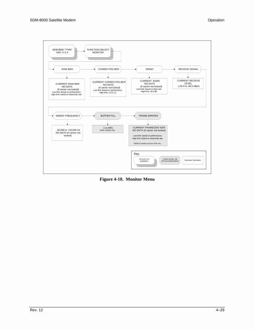
SDM-8000 Satellite Modem Operation
Rev. 12 4–29
SDM-8000 "TYPE"VER: X.X.X
FUNCTION SELECTMONITOR
RAW BER CORRECTED BER EB/NO RECEIVE SIGNAL
SWEEP FREQUENCY BUFFER FILL FRAME ERRORS
CURRENT RAW BERNO DATA
(if carrier not locked)Low limit: based on performance.
High limit: based on data/code rate.
CURRENT CORRECTED BERNO DATA
(if carrier not locked)Low limit: based on performance.
High limit: 1.0 E-12.
CURRENT Eb/N0NO DATA
(if carrier not locked)Low limit: based on data rate.
High limit: 16.0 dB.
CURRENT RECEIVELEVEL
(-25.0 to -60.0 dBm)
-30,000 to +30,000 HzNO DATA (if carrier not
locked)
1 to 99%Buffer Installed Only
CURRENT FRAME/2047 BERNO DATA (if carrier not locked)
Low limit: based on performance.High limit: based on data/code rate.
DEMUX installed and Non-DVB only.
ACCESS TOSUBMENU
CONDITIONAL OROPTION-DEPENDENT Parameter Information
Key:
Figure 4-10. Monitor Menu
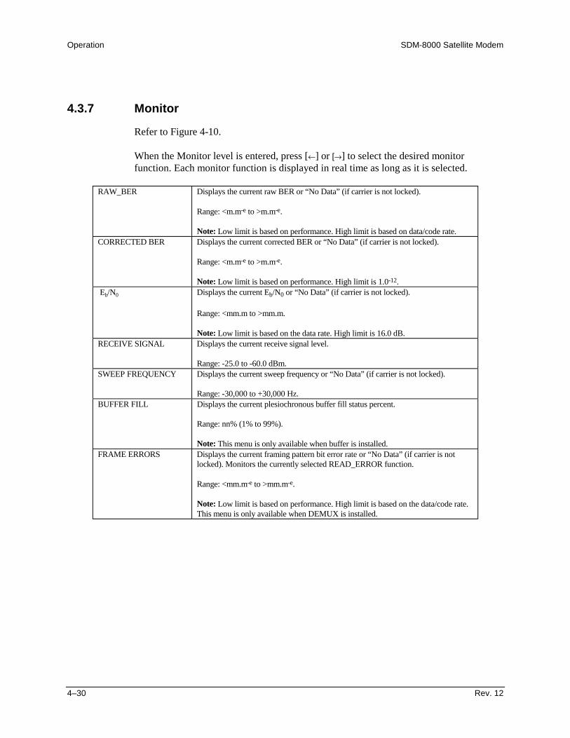
Operation SDM-8000 Satellite Modem
4–30 Rev. 12
4.3.7 Monitor
Refer to Figure 4-10.
When the Monitor level is entered, press [←] or [→] to select the desired monitorfunction. Each monitor function is displayed in real time as long as it is selected.
RAW_BER Displays the current raw BER or “No Data” (if carrier is not locked).
Range: <m.m-e to >m.m-e.
Note: Low limit is based on performance. High limit is based on data/code rate.CORRECTED BER Displays the current corrected BER or “No Data” (if carrier is not locked).
Range: <m.m-e to >m.m-e.
Note: Low limit is based on performance. High limit is 1.0-12. Eb/N0 Displays the current Eb/N0 or “No Data” (if carrier is not locked).
Range: <mm.m to >mm.m.
Note: Low limit is based on the data rate. High limit is 16.0 dB.RECEIVE SIGNAL Displays the current receive signal level.
Range: -25.0 to -60.0 dBm.SWEEP FREQUENCY Displays the current sweep frequency or “No Data” (if carrier is not locked).
Range: -30,000 to +30,000 Hz.BUFFER FILL Displays the current plesiochronous buffer fill status percent.
Range: nn% (1% to 99%).
Note: This menu is only available when buffer is installed.FRAME ERRORS Displays the current framing pattern bit error rate or “No Data” (if carrier is not
locked). Monitors the currently selected READ_ERROR function.
Range: <mm.m-e to >mm.m-e.
Note: Low limit is based on performance. High limit is based on the data/code rate.This menu is only available when DEMUX is installed.

SDM-8000 Satellite Modem Operation
Rev. 12 4–31
SDM-8000 "TYPE"VER: X.X.X
FUNCTION SELECTFAULTS/ALARMS
(see Notes)
MODULATOR DEMODULATOR TX INTERFACE RX INTERFACE
COMMON BACKWARD ALARMS
IF SYNTHESIZERDATA CLOCK ACTDATA CLOCK SYN
I CHANNELQ CHANNELAGC LEVEL
INTERNAL SCT SYNMODULE
EXT REF ACTPROGRAMMING
CONFIGURATION
CARRIER DETECTIF SYNTHESIZERRX CLOCK SYN
I CHANNELQ CHANNEL
DESCRAMBLERBER THRESHOLD
MODULEPROGRAMMING
CONFIGURATION
TX DROPTX DATA/AISTX CLK PLL
TX CLK ACTIVITYPROGRAMMING
CONFIGURATION
BUFFER UNDERFLOWBUFFER OVERFLOW
RX DATA/AISFRAME BER
BACKWARD ALARMBUFFER CLK PLLBUFFER CLK ACT
DEMUX LOCKRX 2047 LOCKBUFFER FULL
RX INSERTPROGRAMMING
CONFIGURATION
BATTERY/CLOCK-12 VOLT SUPPLY+12 VOLT SUPPLY+5 VOLT SUPPLY-5 VOLT SUPPLYCONTROLLER
INTERFACE MODULE
BW ALARM RX #4BW ALARM RX #3BW ALARM RX #2BW ALARM RX #1BW ALARM TX #4BW ALARM TX #3BW ALARM TX #2BW ALARM TX #1
IDR only.
Notes:
1. A “-” indicates that no fault oralarm exists.
2. A “+” indicates that a faultexists, and will cause switchingin a redundant system.
3. A reversed contrast “+”indicates an active alarm.
ACCESS TOSUBMENU
CONDITIONAL OROPTION-DEPENDENT Parameter Information
Key:
Figure 4-11. Faults/Alarms Menu
Operation SDM-8000 Satellite Modem
4–32 Rev. 12
4.3.8 Faults/Alarms
Refer to Figure 4-11.
The Faults/Alarms level is accessible from the Function Select menu. The Faults/Alarmsare similar to monitor functions, as they display the current fault status of the groupbeing displayed.
Press [←] or [→] to move between the following Fault/Alarm groups:
• Modulator• Demodulator• Transmit Interface• Receive Interface• Common Equipment• Backward Alarms (IDR option only)
The current Faults/Alarms status is displayed on line 2 of the display in real time. Foreach parameter monitored, fault status is displayed as one of the following:
• “–” indicates that no fault or alarm exists.
• “+” indicates that a fault exists, and will cause switching in a redundant system.
• Reversed contrast “+” indicates an active alarm.
Alarms do not cause switching to occur. To display labels for individual faults or alarms,press [ENTER].
Press [←] or [→] to move the flashing cursor to make the selection. The label for thatFault/Alarm is then displayed on line 1 of the display. Press [CLEAR] to exit this levelof operation and return to the previous level.
The following sections outline the faults and alarms monitored and displayed in eachgroup.

SDM-8000 Satellite Modem Operation
Rev. 12 4–33
4.3.8.1 Modulator Faults
Refer to Figure 4-11.
Note: Refer to Section 6.2 for more details of the causes of each fault.
IF SYNTHESIZER Modulator IF synthesizer fault.DATA CLOCK ACT Transmit data clock activity alarm. Indicates that data clock activity was not
detected.DATA CLOCK SYN Transmit clock synthesizer fault. Indicates the internal Voltage Controlled
Oscillator (VCO) has not locked to the incoming data clock.I CHANNEL I channel data activity fault.Q CHANNEL Q channel data activity fault.AGC LEVEL TX IF AGC level fault.INTERNAL SCT SYN Internal TX data clock synthesizer fault.MODULE Modulator module fault. Typically indicates that the modulator module is
missing or will not program.EXT REF ACT Modulator fault. Indicates modulator does not have an external reference.
Use this only with the External Reference High Stability option.PROGRAMMING Modulator programming fault. Indicates a front panel programming error
has been made.CONFIGURATION Modulator Configuration fault. Indicates the modulator cannot execute a
programmed configuration parameter.
4.3.8.2 Demodulator Faults
Refer to Figure 4-11.
Note: Refer to Section 6.2 for more details of the causes of each fault.
CARRIER DETECT Carrier detect fault. Indicates the decoder is not locked.IF SYNTHESIZER Demodulator IF synthesizer fault. Indicates the IF synthesizer is not locked.RX CLOCK SYN Receive data clock synthesizer fault. Indicates a loss of lock on the reference
of the demodulator clock recovery oscillator.I CHANNEL I channel activity fault. Indicates a loss of activity in the I channel of the
quadrature demodulator.Q CHANNEL Q channel activity fault. Indicates a loss of activity in the Q channel of the
quadrature demodulator.DESCRAMBLER Descrambler activity alarm. Indicates a loss of activity in the descrambler.BER THRESHOLD Secondary alarm result of the BER threshold set in the DEMOD
Configuration menu.MODULE Demodulator/decoder module fault. Typically indicates that the
demod/decoder module is missing or will not program.PROGRAMMING Demodulator programming fault. Indicates a front panel programming error
has been made.CONFIGURATION Demodulator Configuration fault. Indicates the demodulator cannot execute
a programmed configuration parameter.

Operation SDM-8000 Satellite Modem
4–34 Rev. 12
4.3.8.3 TX Interface Faults
Refer to Figure 4-11.
Note: Refer to Section 6.2 for more details of the causes of each fault.
TX DROP Drop interface hardware fault. Typically indicates that the drop interfacePLL is not locked (D&I only).
TX DATA/AIS Data or AIS. When data fault is selected in the Interface Configurationmenu, the fault indicates a data stable condition. This indicates the datais all 1s or 0s (i.e., data is not transitioning). When AIS is selected, thealarm indicates the data is all 1s from customer data input to the modem.When None is selected in the Interface Configuration menu, the TXData/AIS Fault/Alarm is not activated.
Note: AIS is an Alarm, not a switching fault.TX CLK PLL Transmitter phase-locked loop fault. Indicates the transmitter
Phase-Locked Loop (PLL) is not locked.TX CLK ACTIVITY Activity detector alarm of the selected interface transmit clock. The
interface will fall back to the internal clock when this alarm is active.PROGRAMMING Transmit interface programming fault. Indicates a front panel
programming error has been made.CONFIGURATION Transmit interface configuration fault. Indicates the transmit interface
cannot execute a programmed configuration parameter.
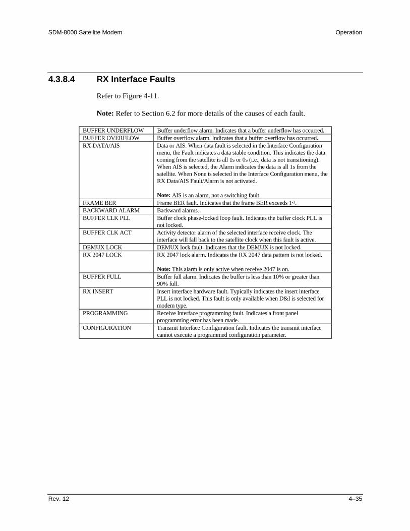
SDM-8000 Satellite Modem Operation
Rev. 12 4–35
4.3.8.4 RX Interface Faults
Refer to Figure 4-11.
Note: Refer to Section 6.2 for more details of the causes of each fault.
BUFFER UNDERFLOW Buffer underflow alarm. Indicates that a buffer underflow has occurred.BUFFER OVERFLOW Buffer overflow alarm. Indicates that a buffer overflow has occurred.RX DATA/AIS Data or AIS. When data fault is selected in the Interface Configuration
menu, the Fault indicates a data stable condition. This indicates the datacoming from the satellite is all 1s or 0s (i.e., data is not transitioning).When AIS is selected, the Alarm indicates the data is all 1s from thesatellite. When None is selected in the Interface Configuration menu, theRX Data/AIS Fault/Alarm is not activated.
Note: AIS is an alarm, not a switching fault.FRAME BER Frame BER fault. Indicates that the frame BER exceeds 1-3.BACKWARD ALARM Backward alarms.BUFFER CLK PLL Buffer clock phase-locked loop fault. Indicates the buffer clock PLL is
not locked.BUFFER CLK ACT Activity detector alarm of the selected interface receive clock. The
interface will fall back to the satellite clock when this fault is active.DEMUX LOCK DEMUX lock fault. Indicates that the DEMUX is not locked.RX 2047 LOCK RX 2047 lock alarm. Indicates the RX 2047 data pattern is not locked.
Note: This alarm is only active when receive 2047 is on.BUFFER FULL Buffer full alarm. Indicates the buffer is less than 10% or greater than
90% full.RX INSERT Insert interface hardware fault. Typically indicates the insert interface
PLL is not locked. This fault is only available when D&I is selected formodem type.
PROGRAMMING Receive Interface programming fault. Indicates a front panelprogramming error has been made.
CONFIGURATION Transmit Interface Configuration fault. Indicates the transmit interfacecannot execute a programmed configuration parameter.

Operation SDM-8000 Satellite Modem
4–36 Rev. 12
4.3.8.5 Common Equipment Faults
Refer to Figure 4-11.
Note: Refer to Section 6.2 for more details of the causes of each fault.
BATTERY/CLOCK Battery or clock fault.-12V SUPPLY -12V power supply fault.+12V SUPPLY +12V power supply fault.+5V SUPPLY +5V power supply fault.-5V SUPPLY -5V power supply fault.CONTROLLER Controller fault. Typically indicates the controller has gone through a
power on/off cycle.INTERFACE MODULE Interface module fault. Typically indicates that the interface module is
missing or will not program.
4.3.8.6 Backward Alarms
Refer to Figure 4-11.
Note: Refer to Section 6.2 for more details of the causes of each fault.
BW Alarm RX #4 Receive backward alarm #4 indicator.BW Alarm RX #3 Receive backward alarm #3 indicator.BW Alarm RX #2 Receive backward alarm #2 indicator.BW Alarm RX #1 Receive backward alarm #1 indicator.BW Alarm TX #4 Transmit backward alarm #4 indicator.BW Alarm TX #3 Transmit backward alarm #3 indicator.BW Alarm TX #2 Transmit backward alarm #2 indicator.BW Alarm TX #1 Transmit backward alarm #1 indicator.
Note: Only available with IDR selected.

SDM-8000 Satellite Modem Operation
Rev. 12 4–37
SDM-8000 "TYPE"VER: X.X.X
FUNCTION SELECTSTORED
FAULTS/ALARMS(see Notes)
MODULATOR x DEMODULATOR x TX INTERFACE x RX INTERFACE x
COMMON x BACKWARDALARMS x
HH:MM:SS/MM-DD-YY
(FAULT LABEL)DATA/CLOCK ACTIVITY
IF SYNTHESIZERDATA CLOCK ACTDATA CLOCK SYN
I CHANNELQ CHANNELAGC LEVEL
INTERNAL SCT SYNMODULE
EXT REF ACTPROGRAMMING
CONFIGURATION
HH:MM:SS/MM-DD-YY
(FAULT LABEL)CARRIER DETECTIF SYNTHESIZERRX CLOCK SYN
I CHANNELQ CHANNEL
DESCRAMBLERBER THRESHOLD
MODULEPROGRAMMING
CONFIGURATION
HH:MM:SS/MM-DD-YY
(FAULT LABEL)TX DROP
TX DATA/AISTX CLK PLL
TX CLK ACTIVITYPROGRAMMING
CONFIGURATION
HH:MM:SS/MM-DD-YY
(FAULT LABEL)BUFFER UNDERFLOWBUFFER OVERFLOW
RX DATA/AISFRAME BER
BACKWARD ALARMBUFFER CLK PLLBUFFER CLK ACT
DEMUX LOCKRX 2047 LOCKBUFFER FULL
RX INSERTPROGRAMMING
CONFIGURATION
HH:MM:SS/MM-DD-YY
(FAULT LABEL)BATTERY/CLOCK-12 VOLT SUPPLY+12 VOLT SUPPLY+5 VOLT SUPPLY-5 VOLT SUPPLYCONTROLLER
INTERFACE MODULE
HH:MM:SS/MM-DD-YY
(FAULT LABEL)BW ALARM RX #4BW ALARM RX #3BW ALARM RX #2BW ALARM RX #1BW ALARM TX #4BW ALARM TX #3BW ALARM TX #2BW ALARM TX #1
IDR only.
Notes:
1. x = 0 to 9.
2. Stored time/date willalternate. HH:MM:SS,MM-DD-YY, or no fault.
UNAVALSECONDS x
HH:MM:SS/MM-DD-YY
see Note 2.Reed-Solomon option only.
CLEAR??
Press [ENTER] to clearstored faults.
ACCESS TOSUBMENU
CONDITIONAL OROPTION-DEPENDENT Parameter Information
Key:
Figure 4-12. Stored Faults/Alarms Menu
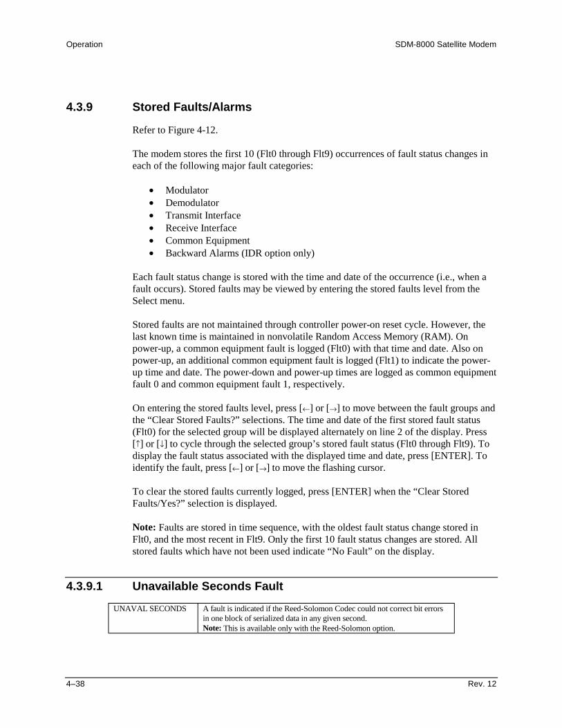
Operation SDM-8000 Satellite Modem
4–38 Rev. 12
4.3.9 Stored Faults/Alarms
Refer to Figure 4-12.
The modem stores the first 10 (Flt0 through Flt9) occurrences of fault status changes ineach of the following major fault categories:
• Modulator• Demodulator• Transmit Interface• Receive Interface• Common Equipment• Backward Alarms (IDR option only)
Each fault status change is stored with the time and date of the occurrence (i.e., when afault occurs). Stored faults may be viewed by entering the stored faults level from theSelect menu.
Stored faults are not maintained through controller power-on reset cycle. However, thelast known time is maintained in nonvolatile Random Access Memory (RAM). Onpower-up, a common equipment fault is logged (Flt0) with that time and date. Also onpower-up, an additional common equipment fault is logged (Flt1) to indicate the power-up time and date. The power-down and power-up times are logged as common equipmentfault 0 and common equipment fault 1, respectively.
On entering the stored faults level, press [←] or [→] to move between the fault groups andthe “Clear Stored Faults?” selections. The time and date of the first stored fault status(Flt0) for the selected group will be displayed alternately on line 2 of the display. Press[↑] or [↓] to cycle through the selected group’s stored fault status (Flt0 through Flt9). Todisplay the fault status associated with the displayed time and date, press [ENTER]. Toidentify the fault, press [←] or [→] to move the flashing cursor.
To clear the stored faults currently logged, press [ENTER] when the “Clear StoredFaults/Yes?” selection is displayed.
Note: Faults are stored in time sequence, with the oldest fault status change stored inFlt0, and the most recent in Flt9. Only the first 10 fault status changes are stored. Allstored faults which have not been used indicate “No Fault” on the display.
4.3.9.1 Unavailable Seconds FaultUNAVAL SECONDS A fault is indicated if the Reed-Solomon Codec could not correct bit errors
in one block of serialized data in any given second.Note: This is available only with the Reed-Solomon option.

SDM-8000 Satellite Modem Operation
Rev. 12 4–39
SDM-8000 "TYPE"VER: X.X.X
FUNCTION SELECTREMOTE AUPC
REMOTE AUPCCONFIGURATION
AUPC ENABLE B-BAND LOOP BACK TX 2047 PATTERN
ONOFF
Control or last known status.
ONOFF
Control or last known status.
ONOFF
Control or last known status.
ACCESS TOSUBMENU
CONDITIONAL OROPTION-DEPENDENT Parameter Information
Key:
Figure 4-13. Remote AUPC Configuration Menu

Operation SDM-8000 Satellite Modem
4–40 Rev. 12
4.3.10 Remote AUPC
Refer to Figure 4-13.
The remote functions may be viewed or changed by entering the remote level from theSelect menu on the front panel. After entering the Remote menu, press [←] or [→] toselect the Configuration or Monitor menu. Enter the selected menu by pressing[ENTER]. Press [←] or [→] to view the selected configuration parameters.
Note: This is only available with the ASYNC overhead option.
4.3.10.1 Remote AUPC Configuration
AUPC ENABLE Programs the AUPC enable On or Off.
On entry, the current status of the remote AUPC is displayed. Press an arrow key tomake the selection. Press [ENTER] to execute the change.
Note: This program is for control or last known status.B-BAND LOOP BACK Programs the remote baseband loopback On or Off.
On entry, the current status of the remote baseband loopback is displayed. Press anarrow key to make the selection. Press [ENTER] to execute the change.
Note: This program is for control or last known status.TX 2047 PATTERN Programs the remote TX 2047 pattern On or Off.
On entry, the current status of the remote TX 2047 is displayed. Press an arrow key tomake the selection. Press [ENTER] to execute the change.
Note: This program is for control or last known status.
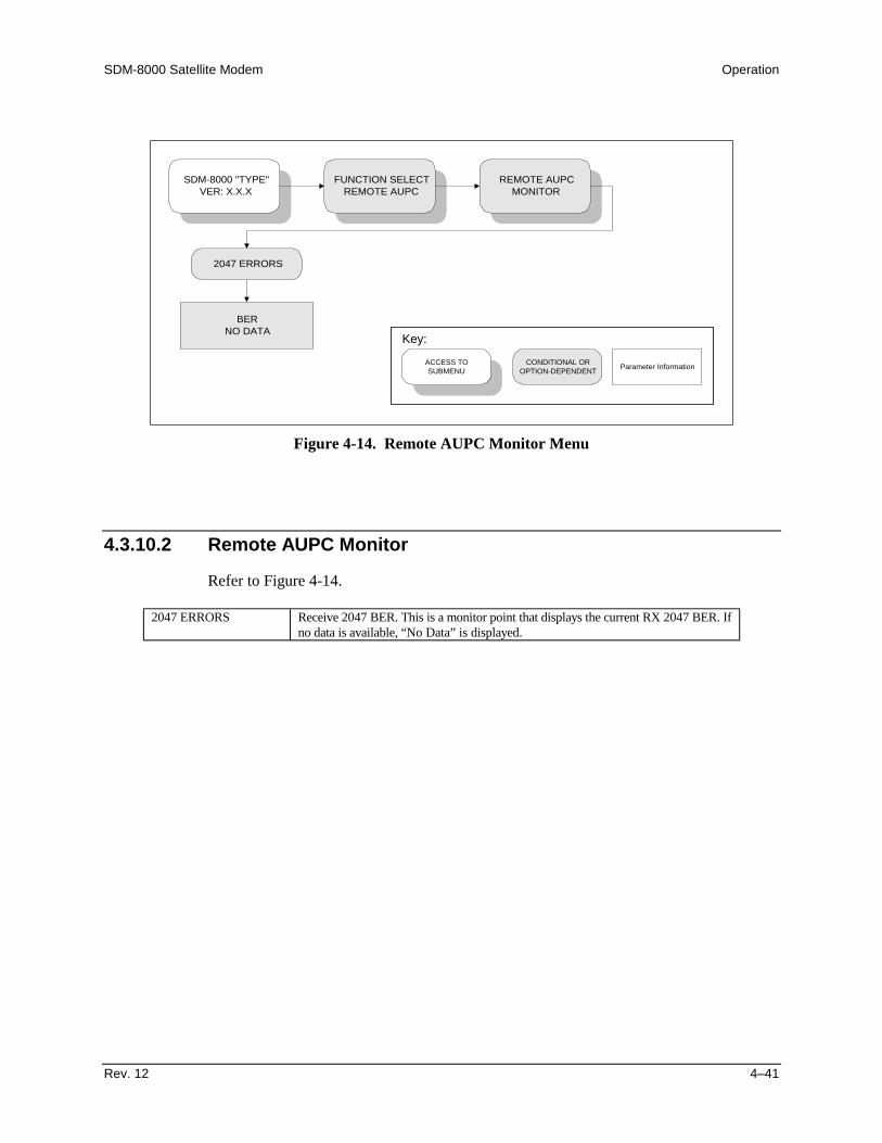
SDM-8000 Satellite Modem Operation
Rev. 12 4–41
SDM-8000 "TYPE"VER: X.X.X
FUNCTION SELECTREMOTE AUPC
REMOTE AUPCMONITOR
2047 ERRORS
BERNO DATA
ACCESS TOSUBMENU
CONDITIONAL OROPTION-DEPENDENT Parameter Information
Key:
Figure 4-14. Remote AUPC Monitor Menu
4.3.10.2 Remote AUPC Monitor
Refer to Figure 4-14.
2047 ERRORS Receive 2047 BER. This is a monitor point that displays the current RX 2047 BER. Ifno data is available, “No Data” is displayed.

Operation SDM-8000 Satellite Modem
4–42 Rev. 12
4.3.11 Utility
The Function Select Utility menu is divided into the following categories:
• Modulator• Demodulator• Interface• System• Modem Type• Factory Setup
Refer to Figures 4-13 through 4-19 for different menu categories. The menu informationincludes:
• Filter Types• Terrestrial Interface Types• Mod/Demod Types• Time/Date• Encoder/Decoder Types• Modem Types• Current Firmware• Test Mode Status• Overhead Type• Revision Emulation• Lamp Test
Provisions are also made for assigning data and code rates to the modulator anddemodulator.
Note: Changes in the Utility menu may cause changes in other front panel menus.
After entering the Utility functions level, press [←] or [→] to select the desired Utilitymenu, and press [ENTER].
Note: The Factory Setup Utility menu is for Comtech EFData service personnel only.Entering this menu without authorization may cause the modem to operate incorrectly.

SDM-8000 Satellite Modem Operation
Rev. 12 4–43
SDM-8000 "TYPE"VER: X.X.X
FUNCTION SELECTUTILITY
UTILITYMODULATOR
ASSIGN TRANSMITFILTERS
MOD POWEROFFSET
MOD POWER FIXEDOFFSET MODULATOR TYPE
ENCODER TYPE MOD SPECTRUM
See Description Table.-49.9 to +49.9 dB,
in 0.1 dB steps
Anything except 0.0 dB will cause“ADJ” to be displayed in the TX
power level screen.
+20.0 to -20.0 dBmStatus only.
INTELSAT OPENEFD CLOSED
Change in custom only.
VITERBISEQUENTIAL
NORMALINVERT
ACCESS TOSUBMENU
CONDITIONAL OROPTION-DEPENDENT Parameter Information
Key:
TX MODULE FWXXX.YYY.ZZZ
FW/NNNNNN-DDRRMM/DD/YY
TX FPGA FWFW/NNNNNN-DDRR
TX FPGA FWMM/DD/YY
TX IESS-310 MODE
ONOFF
8PSK 2/3 andREED-SOLOMON ONLY
Figure 4-15. Utility Modulator Menu

Operation SDM-8000 Satellite Modem
4–44 Rev. 12
4.3.11.1 Utility Modulator
Refer to Figure 4-15.
ASSIGN TRANSMITFILTERS
Transmit filter display/assignment utility. Used to make filter ratereassignments. The modulator has five symbol rate filter presets designated as A, B,C, D, and V.
Viterbi SequentialCode Rate Data Rate Range Data Rate RangeBPSK 1/2 9.6 to 3150.OK 9.6 to 1544.0KQPSK 1/2 19.0 to 6300.0K 19.0 to 2185.0KQPSK 3/4 28.5 to 9312.0K 28.5 to 3277.0KQPSK 7/8 33.25 to 9312.0K 33.25 to 3823.0K8PSK 2/3 38.0 to 9312.0K Not Applicable8PSK 5/6 47.5 to 9312.0K Not Applicable16QAM 3/4 57.0 to 9312.0K Not Applicable16QAM 7/8 64.0 to 9312.0K Not ApplicableQPSK 1/1 38.0 to 9312.0K Not Applicable
Note: Switching between modem types resets the filter presets to their factorydefined values.
To view the current preset assignments, press [ENTER]. TX-A will be on line 1 ofthe display, followed by the code rate (1/2, 3/4, or 7/8). On line 2 will be the datarate assigned to preset A. Press [←] or [→] to view the assignments for presets B, C,D, and V (TX-B, TX-C, TX-D, and TX-V). To change a preset assignment, press[ENTER] when the data for that preset is displayed. Press [←] or [→] until theflashing cursor is at the parameter to be changed, then [↑] or [↓] to change thatparameter. After all changes have been made, press [ENTER] to confirm theassignment. If a preset data/code rate is changed and the modem is currently usingthat preset, the modem will be reprogrammed to the new data/code rate.
MOD POWER OFFSET Modulator power offset adjust. Offsets the modulator output power readout in theConfiguration menu. This feature does not actually change the modulator powerlevel, but displays an offset value in the monitor. The modulator power offset rangeis -49.9 to +49.9 dB, in 0.1 dB steps.
Note: Anything except 0.0 dB will cause ADJ to be displayed in the TX power levelscreen.
MOD POWER FIXEDOFFSET
Modulator power offset (status only). Indicates the power of a modulator that hasbeen provided with extra gain (+20.0 to -20.0 dBm).
Note: This screen displays the fixed modulator power offset for Nominal HighPower options.
MODULATOR TYPE Transmit filter type select. Select INTELSAT OPEN, EFD CLOSED, CSCCLOSED, or FDC CLOSED network filtering.
ENCODER TYPE Encoder type selection. Select Viterbi or Sequential encoder type.TX MODULE FW Displays the transmit module firmware version. The display includes the month,
day, and year.TX FPGA FIRMWARE Displays the firmware installed in the TX field programmable gate array. The
display includes the month, day, and year.MOD SPECTRUM Programmable vector rotation. Allows the operator to select Normal or Inverted
(INVERT) for spectrum reversal of the I and Q baseband channels.

SDM-8000 Satellite Modem Operation
Rev. 12 4–45
TX IESS-310 MODE Programs the IESS-310 On or Off. Used for 8PSK 2/3 andReed-Solomon.
On entry, the current status is displayed. Press an arrow key to make the selection.Press [ENTER] to execute the change.

Operation SDM-8000 Satellite Modem
4–46 Rev. 12
This page is intentionally left blank.

SDM-8000 Satellite Modem Operation
Rev. 12 4–47
SDM-8000 "TYPE"VER: X.X.X
FUNCTION SELECTUTILITY
UTILITYDEMODULATOR
ASSIGN RECEIVERFILTERS
DEMODULATORTYPE DECODER TYPE
RX MODULE FW RX FPGA FIRMWARE DEMOD SPECTRUM
INTELSAT OPENEFD CLOSEDCSC CLOSED
Change in custom only.
VITERBISEQUENTIAL
Change in custom orASYNC.
XXX.YYY.ZZZ
XXX.YYY.ZZZ = Firmware number.
MM/DD/YY =Month/Day/Year.
FW/NNNNNN-DDR
FW/NNNNNN-DDR = Firmware number.
MM/DD/YY = Month/Day/Year.
NORMALINVERT
ACCESS TOSUBMENU
CONDITIONAL OROPTION-DEPENDENT Parameter Information
Key:
See Description Table.
RX IESS-310 MODE
ONOFF
8PSK 2/3 and Reed-Solomon Only
Figure 4-16. Utility Demodulator Menu
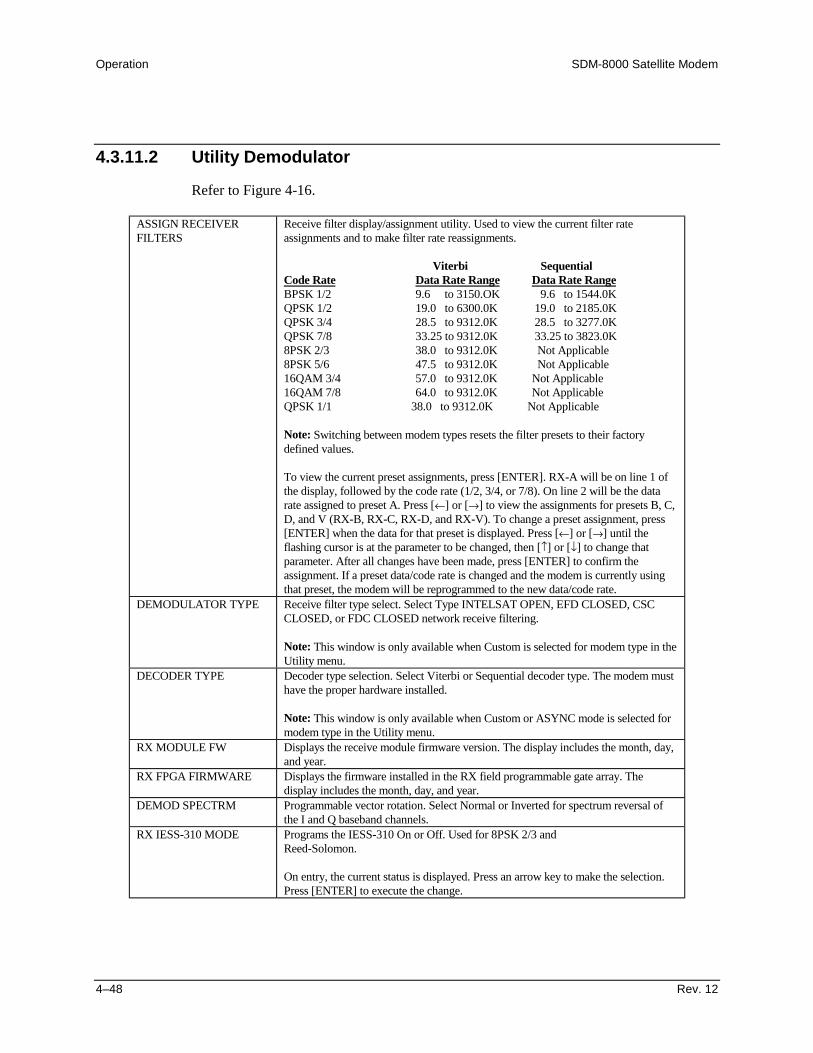
Operation SDM-8000 Satellite Modem
4–48 Rev. 12
4.3.11.2 Utility Demodulator
Refer to Figure 4-16.
ASSIGN RECEIVERFILTERS
Receive filter display/assignment utility. Used to view the current filter rateassignments and to make filter rate reassignments.
Viterbi SequentialCode Rate Data Rate Range Data Rate RangeBPSK 1/2 9.6 to 3150.OK 9.6 to 1544.0KQPSK 1/2 19.0 to 6300.0K 19.0 to 2185.0KQPSK 3/4 28.5 to 9312.0K 28.5 to 3277.0KQPSK 7/8 33.25 to 9312.0K 33.25 to 3823.0K8PSK 2/3 38.0 to 9312.0K Not Applicable8PSK 5/6 47.5 to 9312.0K Not Applicable16QAM 3/4 57.0 to 9312.0K Not Applicable16QAM 7/8 64.0 to 9312.0K Not ApplicableQPSK 1/1 38.0 to 9312.0K Not Applicable
Note: Switching between modem types resets the filter presets to their factorydefined values.
To view the current preset assignments, press [ENTER]. RX-A will be on line 1 ofthe display, followed by the code rate (1/2, 3/4, or 7/8). On line 2 will be the datarate assigned to preset A. Press [←] or [→] to view the assignments for presets B, C,D, and V (RX-B, RX-C, RX-D, and RX-V). To change a preset assignment, press[ENTER] when the data for that preset is displayed. Press [←] or [→] until theflashing cursor is at the parameter to be changed, then [↑] or [↓] to change thatparameter. After all changes have been made, press [ENTER] to confirm theassignment. If a preset data/code rate is changed and the modem is currently usingthat preset, the modem will be reprogrammed to the new data/code rate.
DEMODULATOR TYPE Receive filter type select. Select Type INTELSAT OPEN, EFD CLOSED, CSCCLOSED, or FDC CLOSED network receive filtering.
Note: This window is only available when Custom is selected for modem type in theUtility menu.
DECODER TYPE Decoder type selection. Select Viterbi or Sequential decoder type. The modem musthave the proper hardware installed.
Note: This window is only available when Custom or ASYNC mode is selected formodem type in the Utility menu.
RX MODULE FW Displays the receive module firmware version. The display includes the month, day,and year.
RX FPGA FIRMWARE Displays the firmware installed in the RX field programmable gate array. Thedisplay includes the month, day, and year.
DEMOD SPECTRM Programmable vector rotation. Select Normal or Inverted for spectrum reversal ofthe I and Q baseband channels.
RX IESS-310 MODE Programs the IESS-310 On or Off. Used for 8PSK 2/3 andReed-Solomon.
On entry, the current status is displayed. Press an arrow key to make the selection.Press [ENTER] to execute the change.
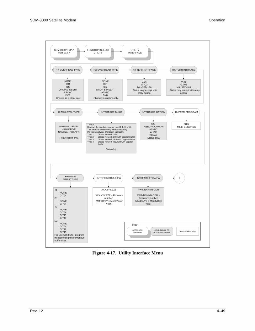
SDM-8000 Satellite Modem Operation
Rev. 12 4–49
SDM-8000 "TYPE"VER: X.X.X
FUNCTION SELECTUTILITY
UTILITYINTERFACE
TX OVERHEAD TYPE RX OVERHEAD TYPE TX TERR INTRFACE
G.703 LEVEL TYPE INTERFACE BUILD INTERFACE OPTION BUFFER PROGRAM
FRAMINGSTRUCTURE INTRFC MODULE FW
NONEIDRIBS
DROP & INSERTASYNC
DVBChange in custom only.
V.35G.703
MIL-STD-188Status only except with
relay option.
NOMINAL LEVELHIGH DRIVE
NOMINAL SHAPED
Relay option only.
TYPE xDisplays the interface module type (1, 2, 3, or 4).This menu is a status-only window reportingthe following types of modem operation:Type 1 Closed Network only.Type 2 Closed Network only with Doppler Buffer.Type 3 Closed Network, IBS with Doppler Buffer.Type 4 Closed Network IBS, IDR with Doppler
Buffer.
Status Only
D&IREED-SOLOMON
ASYNCAUPCRELAY
Status only.
BITSMILLI-SECONDS
T1NONEG.704
E1NONEG.704
T2NONEG.704G.743G.747
E2NONEG.704G.742G.745
For use with buffer programmilliseconds plesiochronousbuffer slips.
XXX.YYY.ZZZ
XXX.YYY.ZZZ = Firmwarenumber.
MM/DD/YY = Month/Day/Year.
INTRFACE FPGA FW
FW/NNNNNN-DDR
FW/NNNNNN-DDR =Firmware number.
MM/DD/YY = Month/Day/Year.
C
NONEIDRIBS
DROP & INSERTASYNC
DVBChange in custom only.
RX TERR INTRFACE
V.35G.703
MIL-STD-188Status only except with relay
option.
ACCESS TOSUBMENU
CONDITIONAL OROPTION-DEPENDENT Parameter Information
Key:
Figure 4-17. Utility Interface Menu

Operation SDM-8000 Satellite Modem
4–50 Rev. 12
E1 INSERT CRC TX DATA PHASE
ONOFF
Enables or disables CRC on insert side of E1.
D&I only.
NORMALINVERT
RX DATA PHASE
NORMALINVERT
IDR BACKWARDALARM CONTROL
BW ALARM RX #XONOFF
BW ALARM TX #XONOFF
X = 1 to 4.
IDR only.
C
ASYNC TX TYPE ASYNC RX TYPE
RS-232RS-485 (2-Wire)RS-485 (4-Wire)
ASYNC overhead optiononly.
UTILITYINTERFACE continued
RS-232RS-485 (2-Wire)RS-485 (4-Wire)
ASYNC overhead optiononly.
ACCESS TOSUBMENU
CONDITIONAL OROPTION-DEPENDENT Parameter Information
Key:
IDR ESC TYPE
64K DATA2-32K AUDIO
IDR Only
TX PLL RESPONSE
ALARMFAULT
Figure 4-17. Utility Interface Menu (Continued)

SDM-8000 Satellite Modem Operation
Rev. 12 4–51
4.3.11.3 Utility Interface
Refer to Figure 4-17.
TX OVERHEAD TYPE Select None, IDR, IBS, D&I, ASYNC, or DVB for TX overhead type.
Note: This window is only available when Custom is selected for modem type inthe Utility menu.
RX OVERHEAD TYPE Select IBS, IDR, D&I, ASYNC, DVB, or None for RX overhead type.
Note: This window is only available when Custom is selected for modem type inthe Utility menu.
TX TERR INTERFACE Displays the TX interface type V.35, G.703, or MIL188.
Note: This menu is status only except with the interface relay board option(RELAY).
RX TERR INTERFACE Displays the RX interface type V.35, G.703, or MIL188.
Note: This menu is status only except with the interface relay board option(RELAY).
G.703 LEVEL TYPE Programs the G.703 level type for the following data rate and pulse-shapedconfigurations:
Configuration Description
NOMINAL LEVEL Rectangular pulse. 1544 kbit/s and 2048 kbit/s. This isthe default.
HIGH DRIVE Rectangular pulse. 8448 Mbit/s.NOMINAL SHAPED A non-standard pulse option for a higher amplitude than
the lower shaped option. This pulse is shaped due toline loss problems.
LOW LEVEL A non-standard pulse option for a lower amplitude thanthe nominal level option.
LOW SHAPED Rectangular pulse. 6312 kbit/s.
On entry, the current G.703 level type is displayed. Press an arrow key to select theconfigurations in the above list. Press [ENTER] to execute the change.
Note: This menu appears only with the interface relay board option (RELAY).INTERFACE BUILD Displays the interface module type (1, 2, 3, or 4). This menu is a status-only
window reporting the following types of modem operation:
Type 1 Closed Network only.Type 2 Closed Network only with Doppler Buffer.Type 3 Closed Network, IBS with Doppler Buffer.Type 4 Closed Network, IBS, IDR with Doppler Buffer.
Note: The two options available with a type 4 are D&I with ASYNC overhead,and Reed-Solomon.
On entry, the current status of the E1 insert CRC is displayed. Press an arrowkey to select ON or OFF. Press [ENTER] to execute the change.

Operation SDM-8000 Satellite Modem
4–52 Rev. 12
INTERFACE OPTION This menu is a status-only window, reporting the following interface options:
• Drop & Insert• Reed-Solomon• ASYNC• AUPC• RELAY
BUFFER PROGRAM Buffer unit program function. Select ms or bits.
Note: To have the modem calculate the plesiochronous shift, set the buffer units toms. When a specific buffer depth is desired, the buffer unit should be set to bits.
FRAMING STRUCTURE Displays the currently selected framing type and structure of the data. This functionis used with the buffer program in ms for plesiochronous buffer slips.
Note: Under G.703 operation, when framing structure is selected, the buffer lengthwill be restricted to multiples of the frame length.
On entry, the framing type (T1, T2, E1, or E2) is displayed on Line 1. The framingstructure of each type is displayed on Line 2. Press an arrow key to select T1, T2,E1, or E2 framing type. Press [ENTER] to change the framing structure of thedisplayed framing type.
Framing Type Framing StructureT1 and E1 None or G.704T2 None, G.704, G.743, or G.747E2 None, G.704, G.742, or G.745
INTRFC MODULE FW Interface module firmware.
Displays the current version of the interface module firmware. The display includesthe month, day, and year.
INTRFC FPGA FW Field programmable gate array firmware. Displays the current version of the FieldProgrammable Gate Array (FPGA) firmware. The display includes the month, day,and year.
E1 INSERT CRC E1 insert CRC enable function. Use this option to turn the CRC-4 on the insert sideof the E1 circuits on or off. The default for this function is on. If the equipmentcannot use the CRC-4 signal, disable the signal by turning it off.
Note: Only available with D&I.TX DATA PHASE TX data phase relationship. Use this option to select Normal or Invert for the TX
data relationship to the selected TX clock.
On entry, press an arrow key to make the selection. Press [ENTER] to execute thechange.
RX DATA PHASE RX data phase relationship. Use this option to select Normal or Invert for the TXdata relationship to the selected RX clock.
On entry, press an arrow key to make the selection. Press [ENTER] to execute thechange.
IDR BACKWARDALARM CONTROL
Controls IDR monitor and alarm functions when not using a communications link.Use this option to select On or Off for the RX and TX alarms.
Press an arrow key to select BW alarm RX or TX numbers 1 through 4. Press[ENTER] to execute the change.

SDM-8000 Satellite Modem Operation
Rev. 12 4–53
IDR ESC TYPE Use this option to select 64K DATA or 2-32K AUDIO. This menu is status only ifIDR is selected through jumpers. It programs the IDR type if a jumper relay boardis used.
On entry, the current status of the IDR ESC TYPE is displayed. Press an arrow keyto make the selection. Press [ENTER] to execute the change.
CAUTION
Jumper setting shall be changed according to Table 4-1. Failure of this optioncan be the result.
Note: This program is only available with the IDR overhead option.ASYNC TX TYPE Programs the ASYNC overhead TX data type for EIA-232 or
EIA-485 (2- or 4-Wire).
On entry, the current status of the ASYNC TX data type is displayed. Press anarrow key to make the selection. Press [ENTER] to execute the change.
Note: This program is only available with the ASYNC overhead option.ASYNC RX TYPE Programs the ASYNC overhead RX data type for EIA-232 or
EIA-485.
On entry, the current status of the ASYNC RX data type is displayed. Press anarrow key to make the selection. Press [ENTER] to execute the change.
Note: This program is only available with the ASYNC overhead option.

Operation SDM-8000 Satellite Modem
4–54 Rev. 12
TX PLL RESPONSE Status Window
Displays either Alarm or Fault.
Table 4-1. Interface Jumper SettingsSummary Indicator Interface Module
JP1, JP2, JP23 TX TERRESTRIAL INTERFACEJP3, JP5, JP22, JP7 RX TERRESTRIAL INTERFACEJP2 IDR TX BW ALARMS (1 through 4)JP5 IDR TX 8KB DATA DRIVERSJP5 IDR RX 8KB DATA DRIVERSJP3 IDR AUDIOMODULATOR SUMMARY INDICATOR MODULATOR TYPEDEMODULATOR SUMMARY INDICATOR DEMODULATOR TYPEMODULATOR SUMMARY INDICATORS ENCODER TYPEDEMODULATOR SUMMARY INDICATORS DECODER TYPE

SDM-8000 Satellite Modem Operation
Rev. 12 4–55
SDM-8000 "TYPE"VER: X.X.X
FUNCTION SELECTUTILITY
UTILITYSYSTEM
TIME: HH:MM:SS AM/PMDATE: MM/DD/YY
REMOTE BAUD RATE XPARITY REMOTE ADDRESS OPERATION MODE
TEST MODE STATUS LAMP TEST???
Current time and date. X =110 2400150 4800300 9600600 192001200X = bps.Parity: even, odd, or none.
1 to 255 DUPLEXTRANSMIT ONLYRECEIVE ONLY
RS DVB ENC OFFRS DVB DEC OFFREED-SOLOMONRX 2047 PATTERNTX 2047 PATTERN
INTRFC LOOP BACKB-BAND LOOP BACK
RF LOOP BACKIF LOOP BACK
CARRIER MODE
Press [ENTER] to turnon all the front panel
indicators for 3 seconds.
MASTER RESET M&C MODULE FW
FW/NNNNNN-DDRMM/DD/YY
FW/NNNNNN-DDR =Firmware number.
MM/DD/YY = Month/Day/Year.
DISPLAY CONTRAST
LEVEL: 0 to 100
EXT AGC: MIN PWR
0 to 10 VOLTS(In 0.5V steps)
Sets the AGC voltage for a receivesignal level of -25.0 dBm.
EXT AGC: MAX PWR
0 to 10 VOLTS(In 0.5V steps)
Sets the AGC voltage for a receivesignal level of -60.0 dBm.
ACCESS TOSUBMENU
CONDITIONAL OROPTION-DEPENDENT Parameter Information
Key:
HARDSOFT
Figure 4-18. Utility System Menu

Operation SDM-8000 Satellite Modem
4–56 Rev. 12
4.3.11.4 Utility System Functions
Refer to Figure 4-18.
TIME: HH:MM:SS AM/PMDATE: MM/DD/YY
Time of day and date display/set function.
The current time and date in the modem’s memory are displayed when selected.To change the modem time and/or date, press [ENTER]. Press [←] or [→] toposition the cursor over the parameter to be changed. Press [↑] or [↓] to changethe parameter. Once the parameters are displayed as desired, press [ENTER] toset the time and date.
REMOTE BAUD RATEx PARITY
The parity and baud rate settings of the modem are displayed.
To change the modem baud rate and/or parity, press [ENTER]. Press [←] or [→]to position the cursor over the parameter to be changed. Press [↑] or [↓] tochange the parameter. Once the parameters are displayed as desired, press[ENTER] to set the baud rate and parity. The parity can be set to Even, Odd, orNone. The baud rate can be set from 110 to 19200 bit/s.
REMOTE ADDRESS The current modem address is displayed (1 to 255).
To change the remote address, press [ENTER]. Press an arrow key to make theselection. Press [ENTER] to execute the change.
Note: Address 0 is reserved for global address.OPERATION MODE Operation mode. Programs the modem for Duplex, RX-only, or TX-only
operation.
On entry, the operational status may be changed. Press an arrow key to make theselection. Press [ENTER] to execute the change.
Note: When TX-only or RX-only is selected, the appropriate faults are maskedfrom the Faults and Stored Faults menus.
TEST MODE STATUS Test mode status indicator. The following modem test points are listed in thiswindow and display a “+” when a test mode is active:
• RS DVB ENC OFF• RS DVB DEC OFF• REED-SOLOMON• RX 2047 PATTERN• TX 2047 PATTERN• INTRFC LOOP BACK• B-BAND LOOP BACK• RF LOOP BACK• IF LOOP BACK• CARRIER MODE
To view the test modes, press [ENTER]. Press an arrow key to make theselection.
LAMP TEST ?? Lamp test function. Press [ENTER] to turn the front panel indicators on forthree seconds.
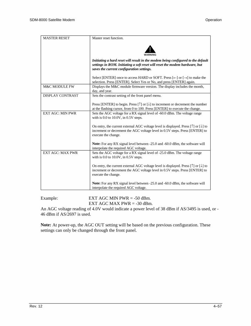
SDM-8000 Satellite Modem Operation
Rev. 12 4–57
MASTER RESET Master reset function.
WARNING
!Initiating a hard reset will result in the modem being configured to the defaultsettings in ROM. Initiating a soft reset will reset the modem hardware, butsaves the current configuration settings.
Select [ENTER] once to access HARD or SOFT. Press [←] or [→] to make theselection. Press [ENTER]. Select Yes or No, and press [ENTER] again.
M&C MODULE FW Displays the M&C module firmware version. The display includes the month,day, and year.
DISPLAY CONTRAST Sets the contrast setting of the front panel menu.
Press [ENTER] to begin. Press [↑] or [↓] to increment or decrement the numberat the flashing cursor, from 0 to 100. Press [ENTER] to execute the change.
EXT AGC: MIN PWR Sets the AGC voltage for a RX signal level of -60.0 dBm. The voltage rangewith is 0.0 to 10.0V, in 0.5V steps.
On entry, the current external AGC voltage level is displayed. Press [↑] or [↓] toincrement or decrement the AGC voltage level in 0.5V steps. Press [ENTER] toexecute the change.
Note: For any RX signal level between -25.0 and -60.0 dBm, the software willinterpolate the required AGC voltage.
EXT AGC: MAX PWR Sets the AGC voltage for a RX signal level of -25.0 dBm. The voltage rangewith is 0.0 to 10.0V, in 0.5V steps.
On entry, the current external AGC voltage level is displayed. Press [↑] or [↓] toincrement or decrement the AGC voltage level in 0.5V steps. Press [ENTER] toexecute the change.
Note: For any RX signal level between -25.0 and -60.0 dBm, the software willinterpolate the required AGC voltage.
Example: EXT AGC MIN PWR = -50 dBm.EXT AGC MAX PWR = -30 dBm.
An AGC voltage reading of 4.0V would indicate a power level of 38 dBm if AS/3495 is used, or -46 dBm if AS/2697 is used.
Note: At power-up, the AGC OUT setting will be based on the previous configuration. Thesesettings can only be changed through the front panel.

Operation SDM-8000 Satellite Modem
4–58 Rev. 12
This page is intentionally left blank.

SDM-8000 Satellite Modem Operation
Rev. 12 4–59
SDM-8000 "TYPE"VER: X.X.X
FUNCTION SELECTUTILITY
UTILITYMODEM TYPE
MODEM TYPECOMPATIBILITY
1 = Option installed and selected.* = Option installed, not selected.0 = Option not installed.x = Don't care, option installed, notactive.X = Don't care, option installed andactive.
MODEM TYPE
IDR (308)IBS (309)CUSTOM
D&IASYNC
DVB TYPE X
(Type X = 1 to 5 - See Note.)
Note:
Type Modem Emulation Operation1 SDM308-4/M1200P IDR2 SDM309/M1200P IBS3 SDM308-5 IBS4 SDM308-4 (Old IDR Interface) IDR5 SDM308-4/M1200P/RS IDR
ACCESS TOSUBMENU
CONDITIONAL OROPTION-DEPENDENT Parameter Information
Key:
REV EMULATION
CURRENT VERSIONFUNCTIONAL X = 2 to 16
Figure 4-19. Utility Modem Type Menu
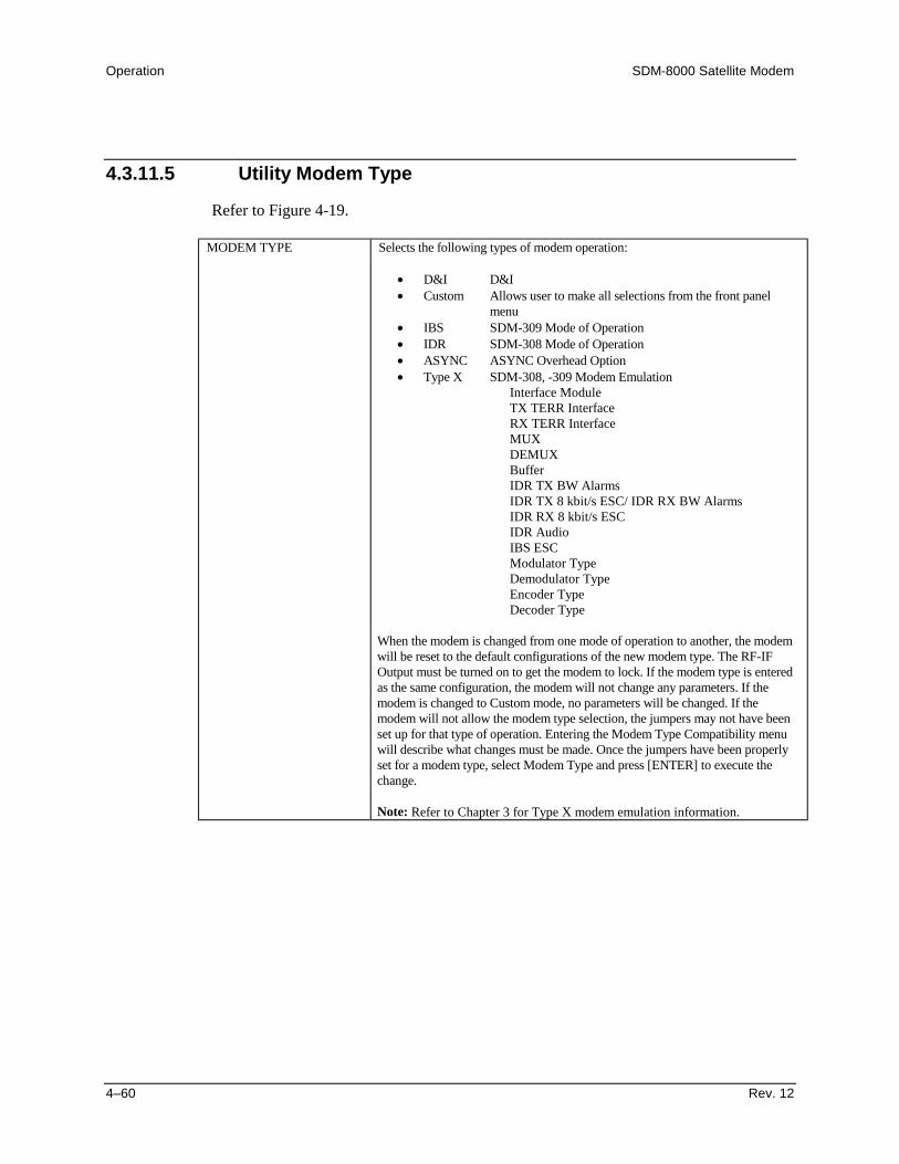
Operation SDM-8000 Satellite Modem
4–60 Rev. 12
4.3.11.5 Utility Modem Type
Refer to Figure 4-19.
MODEM TYPE Selects the following types of modem operation:
• D&I D&I• Custom Allows user to make all selections from the front panel
menu• IBS SDM-309 Mode of Operation• IDR SDM-308 Mode of Operation• ASYNC ASYNC Overhead Option• Type X SDM-308, -309 Modem Emulation
Interface ModuleTX TERR InterfaceRX TERR InterfaceMUXDEMUXBufferIDR TX BW AlarmsIDR TX 8 kbit/s ESC/ IDR RX BW AlarmsIDR RX 8 kbit/s ESCIDR AudioIBS ESCModulator TypeDemodulator TypeEncoder TypeDecoder Type
When the modem is changed from one mode of operation to another, the modemwill be reset to the default configurations of the new modem type. The RF-IFOutput must be turned on to get the modem to lock. If the modem type is enteredas the same configuration, the modem will not change any parameters. If themodem is changed to Custom mode, no parameters will be changed. If themodem will not allow the modem type selection, the jumpers may not have beenset up for that type of operation. Entering the Modem Type Compatibility menuwill describe what changes must be made. Once the jumpers have been properlyset for a modem type, select Modem Type and press [ENTER] to execute thechange.
Note: Refer to Chapter 3 for Type X modem emulation information.
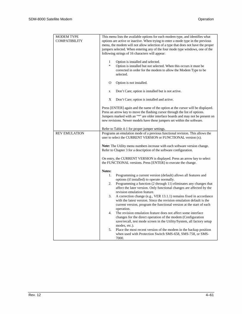
SDM-8000 Satellite Modem Operation
Rev. 12 4–61
MODEM TYPECOMPATIBILITY
This menu lists the available options for each modem type, and identifies whatoptions are active or inactive. When trying to enter a mode type in the previousmenu, the modem will not allow selection of a type that does not have the properjumpers selected. When entering any of the four mode type windows, one of thefollowing strings of 16 characters will appear:
1 Option is installed and selected.* Option is installed but not selected. When this occurs it must be
corrected in order for the modem to allow the Modem Type to beselected.
O Option is not installed.
x Don’t Care; option is installed but is not active.
X Don’t Care; option is installed and active.
Press [ENTER] again and the name of the option at the cursor will be displayed.Press an arrow key to move the flashing cursor through the list of options.Jumpers marked with an “*” are older interface boards and may not be present onnew revisions. Newer models have these jumpers set within the software.
Refer to Table 4-1 for proper jumper settings.REV EMULATION Programs an emulation mode of a previous functional revision. This allows the
user to select the CURRENT VERSION or FUNCTIONAL version (x).
Note: The Utility menu numbers increase with each software version change.Refer to Chapter 3 for a description of the software configuration.
On entry, the CURRENT VERSION is displayed. Press an arrow key to selectthe FUNCTIONAL versions. Press [ENTER] to execute the change.
Notes:1. Programming a current version (default) allows all features and
options (if installed) to operate normally.2. Programming a function (2 through 11) eliminates any changes that
affect the later version. Only functional changes are affected by therevision emulation feature.
3. A correction change (e.g., VER 13.1.1) remains fixed in accordancewith the latest version. Since the revision emulation default is thecurrent version, program the functional version at the start of eachoperation.
4. The revision emulation feature does not affect some interfacechanges for the direct operation of the modem (Configurationsave/recall, test mode screen in the Utility/System, all factory setupmodes, etc.).
5. Place the most recent version of the modem in the backup positionwhen used with Protection Switch SMS-658, SMS-758, or SMS-7000.

Operation SDM-8000 Satellite Modem
4–62 Rev. 12
SDM-8000 "TYPE"VER:X.X.X
FUNCTION SELECTUTILITY
UTILITYFACTORY SETUP
UTILITY FACTORYSETUP
Factory Settings Only.
ACCESS TOSUBMENU
CONDITIONAL OROPTION-DEPENDENT
PARAMETERINFORMATION
Key:
Figure 4-20. Utility Factory Setup Menu
4.3.11.6 Factory Utility Setup
Refer to Figure 4-20.
This configuration is used for factory alignment. Factory setup should not be changed byunauthorized persons. To do so may cause modem failure.
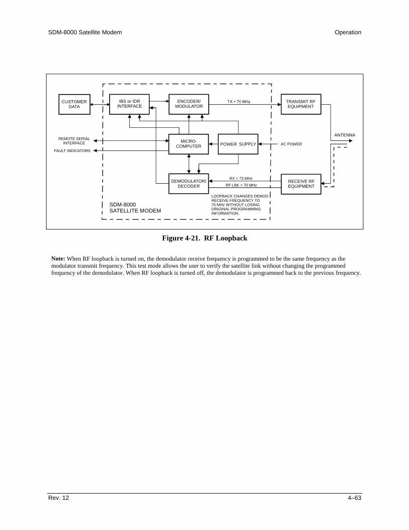
SDM-8000 Satellite Modem Operation
Rev. 12 4–63
CUSTOMERDATA
IBS or IDRINTERFACE
ENCODER/MODULATOR
TRANSMIT RFEQUIPMENT
ANTENNA
AC POWERPOWERMICRO-COMPUTER
REMOTE SERIALINTERFACE
FAULT INDICATORSSUPPLY
RECEIVE RFEQUIPMENT
DEMODULATOR/DECODER
SDM-8000SATELLITE MODEM
LOOPBACK CHANGES DEMODRECEIVE FREQUENCY TO70 MHz WITHOUT LOSINGORIGINAL PROGRAMMINGINFORMATION.
RF LBK = 70 MHz
RX = 73 MHz
Figure 4-21. RF Loopback
Note: When RF loopback is turned on, the demodulator receive frequency is programmed to be the same frequency as themodulator transmit frequency. This test mode allows the user to verify the satellite link without changing the programmedfrequency of the demodulator. When RF loopback is turned off, the demodulator is programmed back to the previous frequency.

Operation SDM-8000 Satellite Modem
4–64 Rev. 12
CUSTOMERDATA
IBS, IDR or 308-2INTERFACE
ENCODER/MODULATOR
TRANSMIT RFEQUIPMENT
ANTENNA
AC POWERPOWER SUPPLYMICRO-COMPUTER
REMOTE SERIALINTERFACE
FAULT INDICATORS
RECEIVE RFEQUIPMENT
DEMODULATOR/DECODER
SDM-8000SATELLITE MODEM
Figure 4-22. IF Loopback
Note: When IF loopback is turned on, the demodulator is looped back to the modulator inside the modem and the demodulatoris programmed to the same frequency as the modulator. This test mode will verify the operation of the modem. When IFloopback is turned off, the demodulator is programmed back to the previous frequency and is reconnected to the IF input.
CUSTOMERDATA
IBS OR IDR
INTERFACE
ENCODER/MODULATOR
TRANSMIT RFEQUIPMENT
ANTENNA
AC POWERPOWER SUPPLYMICRO-
COMPUTERREMOTE SERIAL
INTERFACE
FAULT INDICATORS
RECEIVE RFEQUIPMENT
DEMODULATOR/DECODER
SDM-8000SATELLITE MODEM
Figure 4-23. Baseband Loopback (without D&I)
Note: When baseband loopback is turned on, data is looped back on the customer side of the interface. This is a bidirectionalloopback of the baseband data. This test mode will verify the customer equipment and cabling between the modem and thecustomer equipment. The baseband loopback is not bidirectional in Drop and Insert.
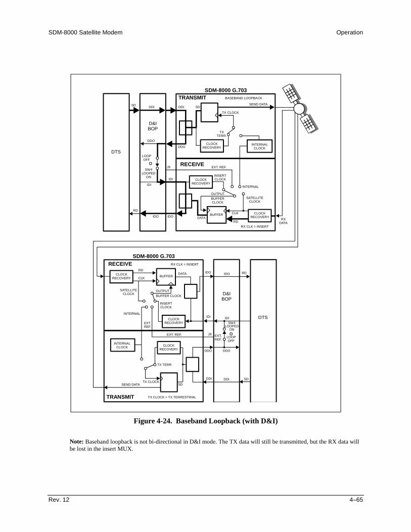
SDM-8000 Satellite Modem Operation
Rev. 12 4–65
TRANSMIT
RECEIVE
SDM-8000 G.703
TX
RDDATA
INTERNALCLOCK
CLOCKRECOVERY
CLOCKRECOVERY
CLOCK
CLK
RXDATA
BUFFER
SEND DATA
BASEBAND LOOPBACK
TXTERR.
SD SDDDI DDI
DDO
DDO
IDI
RD
IDI
IDOIDO
CLOCKRECOVERY
J9
LOOPOFF
LOOPOFF
SW4LOOPED
ON
SW4LOOPED
ON INSERTCLOCK
EXT. REF.
INTERNAL
SATELLITECLOCK
RX CLK = INSERT
BUFFERCLOCK
OUTPUT
DTS
D&IBOP
TRANSMIT
RECEIVESDM-8000 G.703
RDDATA IDO IDO
IDI
J9
IDI
RD
INTERNALCLOCK
CLOCKRECOVERY
CLOCKRECOVERY
TX CLOCK
TX CLOCK = TX TERRESTRIAL
CLK BUFFER
SEND DATA
RX CLK = INSERT
EXT.REF.
EXT. REF.
TX TERR
SD
DDO
DDI
DDO
DDISD
CLOCKRECOVERY
EXT.REF.
INSERTCLOCK
INTERNAL
SATELLITECLOCK BUFFER CLOCK
OUTPUT
DTS
D&IBOP
Figure 4-24. Baseband Loopback (with D&I)
Note: Baseband loopback is not bi-directional in D&I mode. The TX data will still be transmitted, but the RX data willbe lost in the insert MUX.

Operation SDM-8000 Satellite Modem
4–66 Rev. 12
CUSTOMERDATA
IBS OR IDR
INTERFACE
ENCODER/MODULATOR
TRANSMIT RFEQUIPMENT
ANTENNA
AC POWERPOWER SUPPLYMICRO-
COMPUTERREMOTE SERIAL
INTERFACE
FAULT INDICATORS
RECEIVE RFEQUIPMENT
DEMODULATOR/DECODER
SDM-8000SATELLITE MODEM
Figure 4-25. Interface Loopback
Note: When interface loopback in turned on, data is looped back on the modem side of the interface. This is a bidirectionalloopback of the data after the baseband data had the 16/15 overhead added. This test mode will verify the internal channel unitinterface operation.
SDM-8000 Satellite Modem Operation
Rev. 12 4–67
4.4 Clocking Options
Clocking of the data from the terrestrial equipment to the satellite (and vice versa) willdepend on the application. The most common options and recommended configurationsare described in the following sections.
Both Master/Master and Master/Slave applications require a certain amount of bufferdue to Doppler shift caused by the apparent movement of the satellite in distance to theearth station. The Master/Master satellite set-up requires additional buffering due tomismatched station clocks.
4.4.1 IDR/IBS G.703 Master/Master
Refer to Figure 4-26 for the clocking block diagram with transmit and buffer clockoptions.
This application is used when both earth stations have high stability clocks, and thereceived data is to be clocked to the local network. The disadvantage of themaster/master application is that the receive data will slip, as the clocks will not besynchronized. If the buffer is properly set up, the slips will be an exact frame length,causing minimum loss of data. By using very high stability clocks, the expected timebetween slips can be from 20 to 40 days, or infinite days. Loss of the buffer clock willmean the buffer will not be emptied, and data will not be available. The buffer clock willnormally revert to the low stability internal reference automatically.
4.4.2 IDR/IBS G.703 Master/Slave
Refer to Figure 4-27.
This application should be used when the far end earth station does not have local accessto a high stability reference clock, or when it is not required to synchronize with a localclock. The user equipment must loop the timing in G.703 applications
4.4.3 IDR/IBS EIA-422 or V.35 Master/Master
Refer to Figure 4-28 for:
• Clocking block diagram• Transmit clock options• Buffer clock options• V.35 timing signals• EIA-422 timing signals
Operation SDM-8000 Satellite Modem
4–68 Rev. 12
4.4.4 IDR/IBS EIA-422 or V.35 Master/Slave
Refer to Figure 4-29 for:
• Clocking block diagram• Transmit clock options• Buffer clock options• V.35 timing signals• EIA-422 timing signals
Modem loop timing is available in the modem. Loop timing sets the TX and RX clocksto the same clock source. In the CONFIGURATION INTERFACE menu (Figure 4-6),set the loop timing to ON, and select Internal mode for the TX clock. The SCT(INTERNAL) will change to SCT (LOOP) when loop timing is turned ON. The RXbuffer clock should be set to satellite for this application
Notes:1. To compensate for the Doppler shift on the outward and return paths, the length
of the buffer at the master end will need to be twice the length that is normallyrequired.
2. The use of loop timing in the modem also is an option for EIA-422 and V.35operation.
4.4.5 D&I G.703 Master/Master
In the D&I configuration, the most typical clocking option is the master/masterapplication. Refer to Figure 4-30 for:
• Blocking diagram• Transmit clock options• Buffer clock options
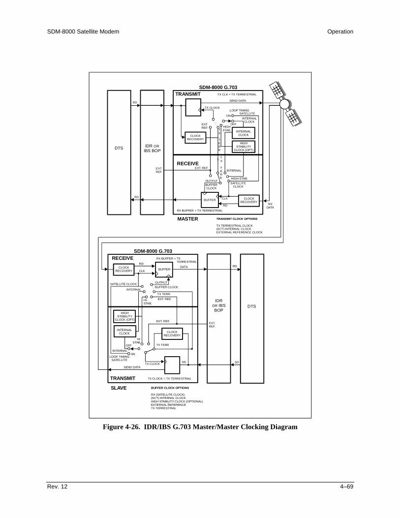
SDM-8000 Satellite Modem Operation
Rev. 12 4–69
TRANSMIT
RECEIVE
MASTER
SDM-8000 G.703
TX
RD
HIGH STAB.
INTERNALCLOCK
HIGHSTABILITY
CLOCK (OPT)
CLOCKRECOVERY
CLOCK
CLK
RXDATA
BUFFER
SEND DATA
TX CLK = TX TERRESTRIAL
TX
TERR
TX
TERR.
SD
LOOP TIMING
ON
HIGHSTAB.
EXT.REF.
OFF
SATELLITE
INTERNALCLOCK
RD
CLOCKRECOVERY
EXT.REF.
EXT. REF.INTERNAL
SATELLITECLOCK
= TX TERRESTRIAL
TRANSMIT CLOCK OPTIONS
TX TERRESTRIAL CLOCK(SCT) INTERNAL CLOCKEXTERNAL REFERENCE CLOCK
BUFFERCLOCK
OUTPUT
DTS IDRIBS BOP
OR
TRANSMIT
RECEIVE
SLAVE
SDM-8000 G.703
RDDATA RD
LOOP TIMINGSATELLITE
INTERNALCLOCK
CLOCKRECOVERY
HIGHSTABILITY
CLOCK (OPT)
TX CLOCK
TX CLOCK = TX TERRESTRIAL
CLK BUFFER
SEND DATA
INTERNAL
R
R
X
X
BUFFER
BUFFER
= TXTERRESTRIAL
EXT. REF.
TX TERR
SDSD
HI-STAB.
OFF
ON
CLOCKRECOVERY
EXT.REF.
TX TERR.
EXT. REF.
INTERNAL
SATELLITE CLOCK
HI-STAB.
BUFFER CLOCK OPTIONS
RX (SATELLITE CLOCK)(SCT) INTERNAL CLOCKHIGH STABILITY CLOCK (OPTIONAL)EXTERNAL REFERENCETX TERRESTRIAL
BUFFER CLOCKOUTPUT
DTSIDR
IBSBOP
OR
Figure 4-26. IDR/IBS G.703 Master/Master Clocking Diagram
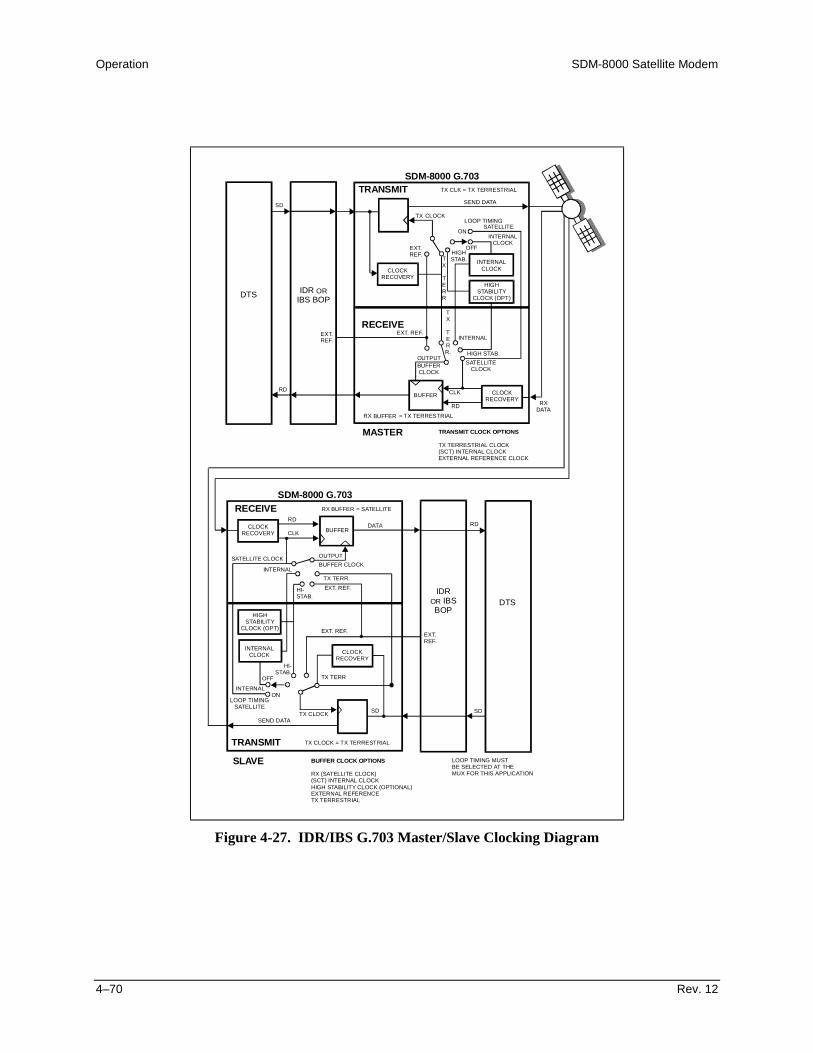
Operation SDM-8000 Satellite Modem
4–70 Rev. 12
TRANSMIT
RECEIVE
MASTER
SDM-8000 G.703
TX
RD
HIGH STAB.
INTERNALCLOCK
HIGHSTABILITY
CLOCK (OPT)
CLOCKRECOVERY
CLOCK
CLK
RXDATA
BUFFER
SEND DATA
TX CLK = TX TERRESTRIAL
TX
TERR
TX
TERR.
SD
LOOP TIMING
ON
HIGHSTAB.
EXT.REF.
OFF
SATELLITEINTERNAL
CLOCK
RD
CLOCKRECOVERY
EXT.REF.
EXT. REF.INTERNAL
SATELLITECLOCK
RX = TX TERRESTRIAL
TRANSMIT CLOCK OPTIONS
TX TERRESTRIAL CLOCK(SCT) INTERNAL CLOCKEXTERNAL REFERENCE CLOCK
BUFFERCLOCK
OUTPUT
DTS IDRIBS BOP
OR
TRANSMIT
RECEIVE
SLAVE
SDM-8000 G.703
RDDATA RD
LOOP TIMINGSATELLITE
INTERNALCLOCK
CLOCKRECOVERY
HIGHSTABILITY
CLOCK (OPT)
TX CLOCK
TX CLOCK = TX TERRESTRIAL
CLK BUFFER
SEND DATA
INTERNAL
RX BUFFER
BUFFER
= SATELLITE
EXT. REF.
TX TERR
SDSD
HI-STAB.
OFF
ON
CLOCKRECOVERY
EXT.REF.
TX TERR.EXT. REF.
INTERNAL
SATELLITE CLOCK
HI-STAB.
BUFFER CLOCK OPTIONS
RX (SATELLITE CLOCK)(SCT) INTERNAL CLOCKHIGH STABILITY CLOCK (OPTIONAL)EXTERNAL REFERENCETX TERRESTRIAL
LOOP TIMING MUSTBE SELECTED AT THEMUX FOR THIS APPLICATION
BUFFER CLOCKOUTPUT
DTSIDR
IBSBOP
OR
Figure 4-27. IDR/IBS G.703 Master/Slave Clocking Diagram
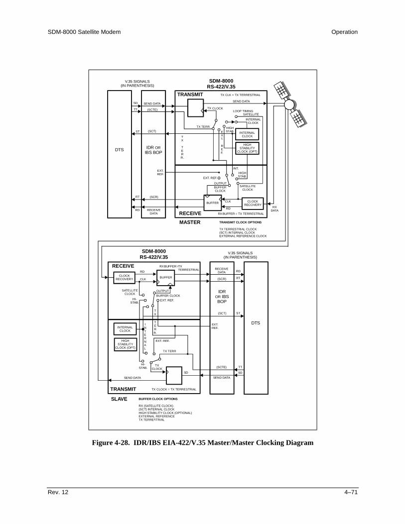
SDM-8000 Satellite Modem Operation
Rev. 12 4–71
TRANSMIT
RECEIVEMASTER
SDM-8000RS-422/V.35
TX
RD
HIGHSTAB.
INTERNALCLOCK
HIGHSTABILITY
CLOCK (OPT)
CLOCKRECOVERY
CLOCK
CLK
RXDATA
BUFFER
SEND DATA
TX CLK = TX TERRESTRIAL
EXT.
REF.
TX
TERR.
SD S
V.35 SIGNALS(IN PARENTHESIS)
V.35 SIGNALS(IN PARENTHESIS)
END DATA
(SCTE)
(SCT)
TT
ST
LOOP TIMING
HIGHSTAB.
TX TERR.
SATELLITEINTERNAL
CLOCK
RD
RT
EXT.REF.
EXT. REF.
(SCR)
RECEIVEDATA
INT.
SATELLITECLOCK
= TX TERRESTRIAL
TRANSMIT CLOCK OPTIONS
TX TERRESTRIAL CLOCK(SCT) INTERNAL CLOCKEXTERNAL REFERENCE CLOCK
BUFFERCLOCK
OUTPUT
DTS IDRIBS BOP
OR
TRANSMIT
RECEIVE
SLAVE
SDM-8000RS-422/V.35
RD
(SCR)
RD
RT
ST
INTERNALCLOCK
CLOCKRECOVERY
HIGHSTABILITY
CLOCK (OPT)
TXCLOCK
TX CLOCK = TX TERRESTRIAL
CLK BUFFER
SEND DATA SEND DATA
(SCTE)
(SCT)
RECEIVEDATA
R
R
X
X
BUFFER
BUFFER
=TXTERRESTRIAL
EXT. REF.
TX TERR
SD
TT
SD
HI-STAB.
EXT.REF.
TERR.
TX
EXT. REF.
INTERNAL
SATELLITECLOCK
HI-STAB.
BUFFER CLOCK OPTIONS
RX (SATELLITE CLOCK)(SCT) INTERNAL CLOCKHIGH STABILITY CLOCK (OPTIONAL)EXTERNAL REFERENCETX TERRESTRIAL
BUFFER CLOCKOUTPUT
DTS
IDRIBS
BOPOR
Figure 4-28. IDR/IBS EIA-422/V.35 Master/Master Clocking Diagram

Operation SDM-8000 Satellite Modem
4–72 Rev. 12
TRANSMIT
RECEIVEMASTER
SDM-8000RS-422/V.35
TX
RD
HIGHSTAB.
INTERNALCLOCK
HIGHSTABILITY
CLOCK (OPT)
CLOCKRECOVERY
CLOCK
CLK
RXDATA
BUFFER
SEND DATA
TX CLK = TX TERRESTRIAL
EXT.
REF.
TX
TERR.
SD SEND DATA
(SCTE)
(SCT)
TT
ST
LOOP TIMING
HIGHSTAB.
TX TERR.
SATELLITEINTERNAL
CLOCK
RD
RT
EXT.REF.
EXT. REF.
(SCR)
RECEIVEDATA
INT.
SATELLITECLOCK
RX BUFFER
RX BUFFER
= TX TERRESTRIAL
TRANSMIT CLOCK OPTIONS
TX TERRESTRIAL CLOCK(SCT) IN
V .35 SIGNALS(IN PARENTHESIS)
V .35 SIGNALS(IN PARENTHESIS)
TERNAL CLOCKEXTERNAL REFERENCE CLOCK
BUFFERCLOCK
OUTPUT
DTS IDRIBS BOP
OR
TRANSMIT
RECEIVE
SLAVE
SDM-8000RS-422/V.35
RD DATA
(SCR)
RD
RT
ST
INTERNALCLOCK
CLOCKRECOVERY
HIGHSTABILITY
CLOCK (OPT)
TXCLOCK
TX CLOCK = TX TERRESTRIAL
CLK BUFFER
SEND DATA SEND DATA
(SCTE)
(SCT)
RECEIVEDATA
= SATELLITE
EXT. REF.
TX TERR
SD
TT
SD
HI-STAB.
EXT.REF.
TERR.
TX
EXT. REF.
INTE
LOOP
RNAL
SATELLITECLOCK
HI-STAB.
BUFFER CLOCK OPTIONS
R LOOP TIMING IN THE MODEM SETS THERECEIVE CLOCK AND TRANSMIT CLOCKTO THE SAME SOURCE. TURN LOOP TIMINGON IN THE CONFIG INTERFACE MENU AND SET TX CLOCK TO SCT (LOOP). THIS SELECTSTHE SATELLITE RECEIVE CLOCK. THE BUFFERCLOCK MUST BE SET TO SATELLITE FOR MODEM LOOP TIMING.
X (SATELLITE CLOCK)(SCT) INTERNAL CLOCKHIGH STABILITY CLOCK (OPTIONAL)EXTERNAL REFERENCETX TERRESTRIAL
BUFFER CLOCKOUTPUT
DTS
IDRIBS
BOPOR
Figure 4-29. IDR/IBS EIA-422/V.35 Master/Slave Clocking Diagram
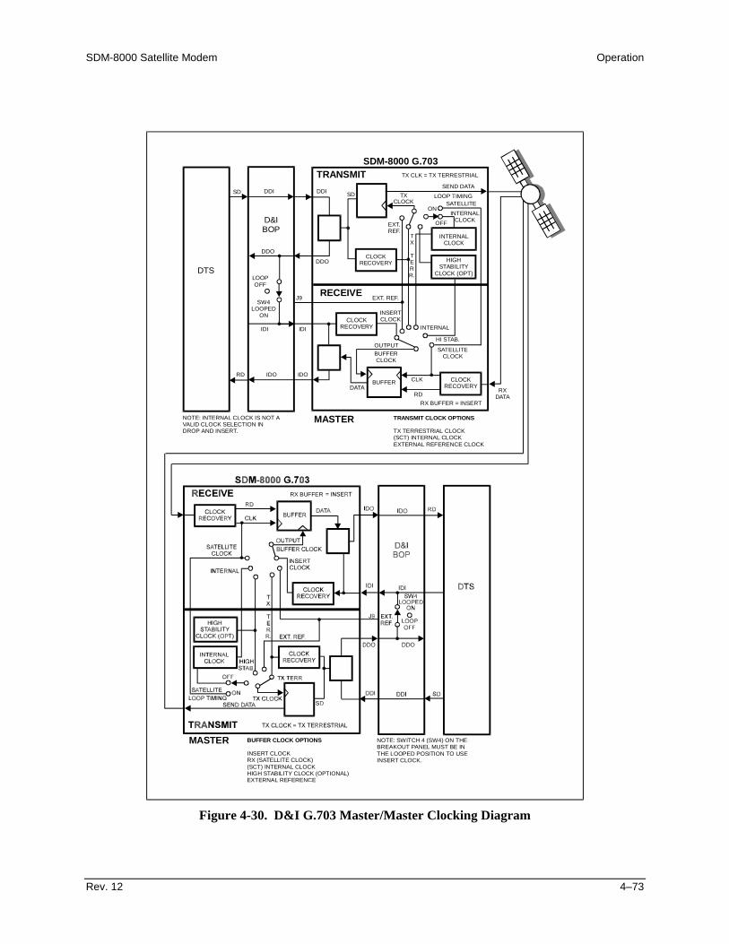
SDM-8000 Satellite Modem Operation
Rev. 12 4–73
TRANSMIT
RECEIVE
SDM-8000 G.703
TX
RDDATA
INTERNALCLOCK
HIGHSTABILITY
CLOCK (OPT)
CLOCKRECOVERY
CLOCKRECOVERY
CLOCK SATELLITEINTERNAL
CLOCK
LOOP TIMING
CLK
RXDATA
BUFFER
SEND DATA
TX CLK = TX TERRESTRIAL
TX
TERR.
EXT.REF.
SD SD
OFF
ON
DDI DDI
DDO
DDO
IDI
RD
IDI
IDOIDO
CLOCKRECOVERY
J9
LOOPOFF
SW4LOOPED
ON INSERTCLOCK
EXT. REF.
HI STAB.
INTERNAL
SATELLITECLOCK
RX BUFFER
RX BUFFER
= INSERT
BUFFERCLOCK
OUTPUT
DTS
D&IBOP
MASTER TRANSMIT CLOCK OPTIONS
TX TERRESTRIAL CLOCK(SCT) INTERNAL CLOCKEXTERNAL REFERENCE CLOCK
NOTE: INTERNAL CLOCK IS NOT AVALID CLOCK SELECTION INDROP AND INSERT.
MASTER BUFFER CLOCK OPTIONS
INSERT CLOCKRX (SATELLITE CLOCK)(SCT) INTERNAL CLOCKHIGH STABILITY CLOCK (OPTIONAL)EXTERNAL REFERENCE
NOTE: SWITCH 4 (SW4) ON THEBREAKOUT PANEL MUST BE INTHE LOOPED POSITION TO USEINSERT CLOCK.
Figure 4-30. D&I G.703 Master/Master Clocking Diagram


Rev. 12 5–1
5Chapter 5. THEORY OF OPERATION
This chapter contains the theory of operation for the modem PCBs, and discussesmodulation types.
5.1 Display/M&C
The Display/M&C PCB is located on the front panel. This card, referred to as the M&C,monitors the modem and provides configuration updates to other modules within themodem when necessary.
The modem configuration parameters are maintained in battery-backed RAM, whichprovides total recovery after a power-down situation.
The M&C functions include extensive fault monitoring and status reporting.
All modem functions are accessible through a local front panel interface and a remotecommunications interface.
Refer to Chapter 3 for a diagram of the M&C card. A block diagram of the M&C isshown in Figure 5-1.

Theory of Operation SDM-8000 Satellite Modem
5–2 Rev. 12
5.1.1 Theory of Operation
The M&C card is composed of the following subsections:
• Microcontroller• Digital to Analog Converter (DAC)• Read Only Memory (ROM)• Analog to Digital Converter (ADC)• RAM• Inter-Modem Communications• Universal ASYNC• User Interface• Receiver/Transmitter (UART)
16 MHzCLOCK
ROM
DACI C BUS2
USER INTERFACE
FRONT PANELLEDs
KEYBOARDSOUNDER (BEEPER)
ADC
INTER-MODEM COMMUNICATIONS
SYSTEM INTERFACECONNECTOR (JP4)
TO
REMOTE PORTRS-232OR
RS-485UART
MICRO-CONTROLLER RAM
ANDREAL TIME
CLOCK
Figure 5-1. Display/M&C Block Diagram

SDM-8000 Satellite Modem Theory of Operation
Rev. 12 5–3
The heart of the M&C card is the Intel 80C32 (or a compatible microcontroller)operating at 16 MHz. This microcontroller contains 256 kbit/s of internal RAM. A ROMat U17 can be:
• 27C010 (128 kbit/s)• 27C020 (256 kbit/s)• 27C040 (512 kbit/s)
ROM access times must be equal to or greater than 200 Ns. The correct ROM size can beset by jumpers JP9 and JP10. The RAM can be 8 kbit/s or 32 kbit/s in size. This RAMchip is internally battery-backed, and contains a real time clock used by the M&C.
The non-volatile RAM on the M&C module allows the module to retain configurationinformation without prime power for up to one year. If the modem is powered down, thefollowing sequence is carried out by the M&C microcontroller:
1. When power is applied to the M&C, the microcontroller checks the nonvolatilememory to see if valid data has been retained. If valid data has been retained, themodem is reconfigured to the parameters maintained in RAM.
2. If the nonvolatile memory fails the valid data test, a default configuration fromROM is loaded into the system.
The UART supports serial ASYNC communications channels (remote port) with amaximum data rate of 19200 bit/s. The UART is memory-mapped to the microcontroller.The communications type can be EIA-232 or EIA-485 (set with M&C jumpers JP1 andJP5). For EIA-485 communications, 2- or 4-wire operation can be set by jumpers JP2 andJP3. The remote port is connected to the M&C system interface connector (JP4).
The DAC supplies a voltage that controls the contrast of the display. The ADC monitorsall the voltages from the power supply. The DAC and ADC are mapped to themicrocontroller with an Integrated Circuit (IC) bus.
The inter-modem communications uses the internal serial port located in themicrocontroller. The inter-modem communications are connected to the M&C systeminterface connector (JP4) for communication between the modulator, demodulator, andinterface cards.
The user interface includes the following parts:
• Front panel• Status LEDs• Keyboard• Sounder (beeper)
All functions are memory-mapped to the microcontroller.

Theory of Operation SDM-8000 Satellite Modem
5–4 Rev. 12
5.2 Modulator
The modulator PCB is a 10.25 x 17.00 inches (25 x 43 cm) assembly that fits in the topslot of the modem chassis. The modulator provides PSK and QAM modulated carrierswithin the 50 to 180 MHz range. The types of modulation that encode the transmittedbaseband data from the interface PCB are:
• BPSK • 8PSK• QPSK • 16QAM
Refer to Section 5.2.3 for a description of each modulation type. Refer to Chapter 3 for adiagram of the modulator PCB and modulator jumper settings. A block diagram of themodulator is shown in Figure 5-2.
IF FILTER VARIABLE
VARIABLE
ATTENUATOR
ATTENUATOR
IF OUTPUT
IF LOOPBACK
CLOCK SYNTH:1 x 10E-5 STABILITY
MPC
RFSYNTH
REFVCXO
MPC
DDS0 90
VCO
HIGHSTABILITY
OSCILLATORPLL
SCTDDS
MPC
PLLEXT. CLOCK
EXT. REF (OPTIONAL)
(OPTIONAL)
TX_DATA
MPC MPC
MPC
DIGITAL
DIGITAL
NYQUIST
NYQUIST
DAC
DAC
ALIAS
ALIAS
FILTER
FILTER
VECTORROTATIONQ
ICONVOLUTIONAL
CONVOLUTIONAL
ENCODERS
ENCODERS
SCRAMBLERS &DIFFERENTIAL
ENCODERTX_CLOCK
MICRO-PROCESSOR
MPC
MUX
50 to 180 MHz-5 to -30 dBm
M&CCOMMAND
BUS
Figure 5-2. Modulator Block Diagram
SDM-8000 Satellite Modem Theory of Operation
Rev. 12 5–5
5.2.1 Modulator Specifications
Refer to Appendix C for Modulator specifications.
5.2.2 Theory of Operation
The modulator is composed of eight basic subsections. These subsections are dividedinto the baseband processing section and the RF section of the modulator. The modulatorM&C controls all programmable functions on this module. Fault information from themodulator is sent to the host M&C. Refer to Chapter 6 for a list of reported faults.
The major modulator PCB subsections are:
• Slave Microprocessor• I/Q Nyquist Filters• Scrambler/Differential Encoder• Modulator• Convolutional Encoder• RF Synthesizer• Programmable Vector Rotation• Output Amplifier
The format for the digital data stream from the interface PCB is EIA-422, and includes aclock synchronous with the data. At this point, the data is clean and free of jitter. Thedata is sent to the scrambler for energy dispersal, and then to the differential encoder.The differential encoder is a 2-bit encoder which allows for resolution of two of the fourambiguity states of the QPSK demodulator.
The data is sent to the convolutional encoder for encoding the data rates of thetransmitted baseband data. The code rates 1/2, 3/4, and 7/8 are based on the symbol raterange of 9.6 kbit/s to 6.3 Mbit/s. For Viterbi codes, the convolutional encoder encodesthe data at 1/2 rate. If the selected code rate is 3/4, then 2 of every 6 symbols arepunctured. For 3-bits in, there are 4 symbols out.
For sequential codes, the convolutional encoder generates the parity bits from the inputdata stream, which allows for error correction at the far end of the link. The rate of theencoder may be 1/2, 3/4, or 7/8. For example, the 7/8 rate puts out 8 symbols for every7 bits in. If the modulator is in the QPSK mode, the data is split into two separate datastreams to drive the I and Q channels of the modulator. Refer to Section 5.6 for thetheory of modulation types.
After the convolutional encoder, the data is sent to a programmable vector rotationcircuit. This feature provides the user with data communications compatibility forspectrum reversal of the I and Q channels before and after satellite transmission.
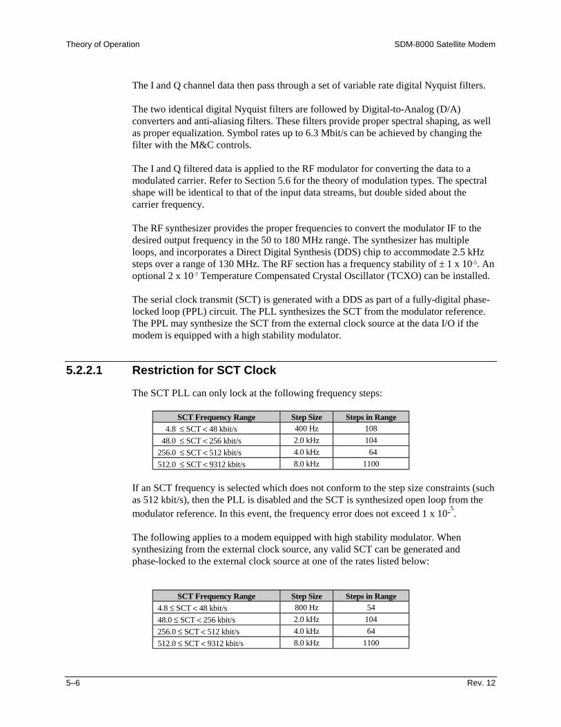
Theory of Operation SDM-8000 Satellite Modem
5–6 Rev. 12
The I and Q channel data then pass through a set of variable rate digital Nyquist filters.
The two identical digital Nyquist filters are followed by Digital-to-Analog (D/A)converters and anti-aliasing filters. These filters provide proper spectral shaping, as wellas proper equalization. Symbol rates up to 6.3 Mbit/s can be achieved by changing thefilter with the M&C controls.
The I and Q filtered data is applied to the RF modulator for converting the data to amodulated carrier. Refer to Section 5.6 for the theory of modulation types. The spectralshape will be identical to that of the input data streams, but double sided about thecarrier frequency.
The RF synthesizer provides the proper frequencies to convert the modulator IF to thedesired output frequency in the 50 to 180 MHz range. The synthesizer has multipleloops, and incorporates a Direct Digital Synthesis (DDS) chip to accommodate 2.5 kHzsteps over a range of 130 MHz. The RF section has a frequency stability of ± 1 x 10⁻⁵. Anoptional 2 x 10⁻⁷ Temperature Compensated Crystal Oscillator (TCXO) can be installed.
The serial clock transmit (SCT) is generated with a DDS as part of a fully-digital phase-locked loop (PPL) circuit. The PLL synthesizes the SCT from the modulator reference.The PPL may synthesize the SCT from the external clock source at the data I/O if themodem is equipped with a high stability modulator.
5.2.2.1 Restriction for SCT Clock
The SCT PLL can only lock at the following frequency steps:
SCT Frequency Range Step Size Steps in Range 4.8 ≤ SCT < 48 kbit/s 400 Hz 108 48.0 ≤ SCT < 256 kbit/s 2.0 kHz 104256.0 ≤ SCT < 512 kbit/s 4.0 kHz 64512.0 ≤ SCT < 9312 kbit/s 8.0 kHz 1100
If an SCT frequency is selected which does not conform to the step size constraints (suchas 512 kbit/s), then the PLL is disabled and the SCT is synthesized open loop from themodulator reference. In this event, the frequency error does not exceed 1 x 10⁻⁵.
The following applies to a modem equipped with high stability modulator. Whensynthesizing from the external clock source, any valid SCT can be generated andphase-locked to the external clock source at one of the rates listed below:
SCT Frequency Range Step Size Steps in Range4.8 ≤ SCT < 48 kbit/s 800 Hz 5448.0 ≤ SCT < 256 kbit/s 2.0 kHz 104256.0 ≤ SCT < 512 kbit/s 4.0 kHz 64512.0 ≤ SCT < 9312 kbit/s 8.0 kHz 1100

SDM-8000 Satellite Modem Theory of Operation
Rev. 12 5–7
The lowest frequency range is composed of 800 Hz steps (as opposed to 400 Hz steps forthe modulator reference mode). If an SCT frequency is selected which does not conformto the step size constraints (such as 512 kbit/s), then the PLL is disabled and the SCT issynthesized open loop from the modulator reference. In this event, the frequency errordoes not exceed 1 x 10⁻⁵.
The signal from the power combiner is sent to the output amplifier. The amplifier takesthe low level signal from the modulator section and amplifies the signal to the properlevel for output from the module. The amplifier circuitry provides programmable controlof the output level over a range of -5 to -30 dBm, in 0.1 dB steps. The amplifier haspower leveling of ± 0.5 dB to maintain the stability of the output level over time andtemperature. The +5 dB output option has a high power oscillator capable of outputting+5 to -20 dBm.
5.2.3 Theory of Modulation Types
The modulation types for the modem include:
• BPSK• QPSK• 8PSK• 16QAM
The PSK data transmission encoding method uses the phase modulation technique. Thismethod varies the phase angle of the carrier wave to represent a different bit value for thereceiver. The higher levels of modulation are required for an operating range that has alimited bandwidth.
The QAM method uses a combination of differential phase shifts and amplitudes totaling16 different states to represent a different bit value for the receiver.
The order of modulation is represented by mPSK, where “m” relates to the number ofdiscrete phase angles. Refer to the following list for a brief description of the modulationtypes.
• BPSK 2 discrete phase angles represent the 2 possible states of 1 symbol• QPSK 4 discrete phase angles represent the 4 possible states of 2 symbols• 8PSK 8 discrete phase angles represent the 8 possible states of 3 symbols• 16QAM 16 discrete phase angles represent the 16 possible states of 4
symbols
Note: The code rate determines the number of symbols per bit.
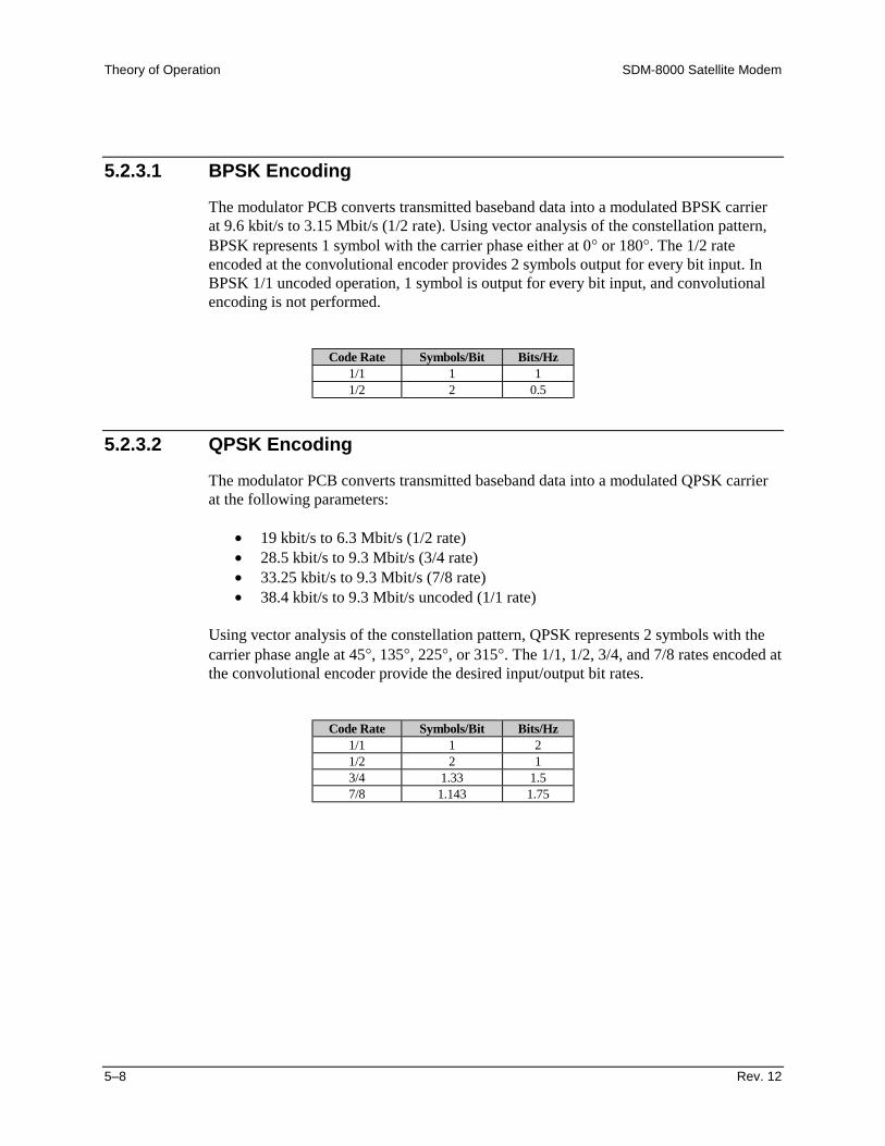
Theory of Operation SDM-8000 Satellite Modem
5–8 Rev. 12
5.2.3.1 BPSK Encoding
The modulator PCB converts transmitted baseband data into a modulated BPSK carrierat 9.6 kbit/s to 3.15 Mbit/s (1/2 rate). Using vector analysis of the constellation pattern,BPSK represents 1 symbol with the carrier phase either at 0° or 180°. The 1/2 rateencoded at the convolutional encoder provides 2 symbols output for every bit input. InBPSK 1/1 uncoded operation, 1 symbol is output for every bit input, and convolutionalencoding is not performed.
Code Rate Symbols/Bit Bits/Hz1/1 1 11/2 2 0.5
5.2.3.2 QPSK Encoding
The modulator PCB converts transmitted baseband data into a modulated QPSK carrierat the following parameters:
• 19 kbit/s to 6.3 Mbit/s (1/2 rate)• 28.5 kbit/s to 9.3 Mbit/s (3/4 rate)• 33.25 kbit/s to 9.3 Mbit/s (7/8 rate)• 38.4 kbit/s to 9.3 Mbit/s uncoded (1/1 rate)
Using vector analysis of the constellation pattern, QPSK represents 2 symbols with thecarrier phase angle at 45°, 135°, 225°, or 315°. The 1/1, 1/2, 3/4, and 7/8 rates encoded atthe convolutional encoder provide the desired input/output bit rates.
Code Rate Symbols/Bit Bits/Hz1/1 1 21/2 2 13/4 1.33 1.57/8 1.143 1.75
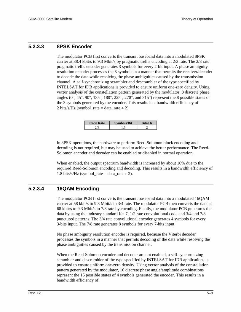
SDM-8000 Satellite Modem Theory of Operation
Rev. 12 5–9
5.2.3.3 8PSK Encoder
The modulator PCB first converts the transmit baseband data into a modulated 8PSKcarrier at 38.4 kbit/s to 9.3 Mbit/s by pragmatic trellis encoding at 2/3 rate. The 2/3 ratepragmatic trellis encoder generates 3 symbols for every 2-bit input. A phase ambiguityresolution encoder processes the 3 symbols in a manner that permits the receiver/decoderto decode the data while resolving the phase ambiguities caused by the transmissionchannel. A self-synchronizing scrambler and descrambler of the type specified byINTELSAT for IDR applications is provided to ensure uniform one-zero density. Usingvector analysis of the constellation pattern generated by the modulator, 8 discrete phaseangles (0°, 45°, 90°, 135°, 180°, 225°, 270°, and 315°) represent the 8 possible states ofthe 3 symbols generated by the encoder. This results in a bandwidth efficiency of2 bits/s/Hz (symbol_rate = data_rate ÷ 2).
Code Rate Symbols/Bit Bits/Hz2/3 1.5 2
In 8PSK operations, the hardware to perform Reed-Solomon block encoding anddecoding is not required, but may be used to achieve the better performance. The Reed-Solomon encoder and decoder can be enabled or disabled in normal operation.
When enabled, the output spectrum bandwidth is increased by about 10% due to therequired Reed-Solomon encoding and decoding. This results in a bandwidth efficiency of1.8 bits/s/Hz (symbol_rate = data_rate ÷ 2).
5.2.3.4 16QAM Encoding
The modulator PCB first converts the transmit baseband data into a modulated 16QAMcarrier at 58 kbit/s to 9.3 Mbit/s in 3/4 rate. The modulator PCB then converts the data at68 kbit/s to 9.3 Mbit/s in 7/8 rate by encoding. Finally, the modulator PCB punctures thedata by using the industry standard K= 7, 1/2 rate convolutional code and 3/4 and 7/8punctured patterns. The 3/4 rate convolutional encoder generates 4 symbols for every3-bits input. The 7/8 rate generates 8 symbols for every 7-bits input.
No phase ambiguity resolution encoder is required, because the Viterbi decoderprocesses the symbols in a manner that permits decoding of the data while resolving thephase ambiguities caused by the transmission channel.
When the Reed-Solomon encoder and decoder are not enabled, a self-synchronizingscrambler and descrambler of the type specified by INTELSAT for IDR applications isprovided to ensure uniform one-zero density. Using vector analysis of the constellationpattern generated by the modulator, 16 discrete phase angle/amplitude combinationsrepresent the 16 possible states of 4 symbols generated the encoder. This results in abandwidth efficiency of:

Theory of Operation SDM-8000 Satellite Modem
5–10 Rev. 12
• 3 bits/s/Hz in 3/4 rate (symbol_rate = data_rate ÷ 2)• 3.5 bits/s/Hz in 7/8 rate (symbol_rate = data_rate ÷ 3.5)
Code Rate Symbols/Bit Bit/Hz3/4 1.33 37/8 1.143 3.5
In 16QAM operation, the hardware to perform Reed-Solomon block encoding anddecoding is required to achieve the best operational characteristics and performance.
Although the Reed-Solomon encoder and decoder can be disabled for test purposes,proper operation may not be realized, thus requiring that they be enabled for normaloperation. A synchronous scrambler and descrambler of the type specified byINTELSAT for Reed-Solomon outer Codec use is provided to ensure uniform one-zerodensity. The output spectrum bandwidth is increased by about 10% due to the requiredReed-Solomon encoding and decoding. This action results in a bandwidth efficiency of:
• 2.7 bits/s/Hz in 3/4 rate (symbol_rate = data_rate ÷ 2.7)• 3.15 bits/s/Hz in 7/8 rate (symbol_rate = data_rate ÷ 3.15)

SDM-8000 Satellite Modem Theory of Operation
Rev. 12 5–11
5.3 Demodulator
The modem demodulator PCB is 10.25 x 17.00 inches (26 x 43 cm), and fits in thebottom slot of the modem chassis. The demodulator converts PSK modulated carrierswithin the 50 to 180 MHz range to a demodulated baseband data stream. Thedemodulator then performs FEC on the data stream using the Viterbi decoding algorithm.A block diagram is shown in Figure 5-3. Refer to Chapter 3 for a diagram of thedemodulator PCB and demodulator jumper settings. The converted modulation types are:
• BPSK • 8PSK• QPSK • 16QAM
Note: Viterbi decoding is not used with the uncoded operation.
DIGITALA/DALIASIRF MODULE
IFLOOPBACK
IF FILTER
FILTER
ALIASFILTER
Q
NYQUIST
A/D DIGITALNYQUIST
AOC
DIGITALCLOCKLOOP
SOFTDECISIONMAPPING
DIGITALCOSTAS
AOC900
VCO
MPC RFSYNTH
IF INPUT
AGC
DDSMPC
LOOP
UNCODED DATAFORMATTER AND
VECTORROTATION
ORSEQUENTIAL
VITERBI DECODER
DIFFERENTIALDECODERS
ALTERNATE
RXDATA
DDS
MPC
MPC
MPCMPC
MPC
MPC
DECODER(OPTION)
TO HOST M&C LOCAL M&C(MICROPROCESSOR) RX
CLOCK
50 to 180 MHz-30 to -55 dBm
AGC/AOC
Figure 5-3. Demodulator Block Diagram

Theory of Operation SDM-8000 Satellite Modem
5–12 Rev. 12
5.3.1 Demodulator Specifications
Refer to Appendix C for Demodulator specifications.
5.3.2 Theory of Operation
Note: Refer to Section 5.2.3 for modulation types.
The demodulator PCB functions as an advanced digital coherent phase-lock receiver andViterbi decoder (or optional sequential decoder). An on-board microprocessor (localM&C) controls all programmable functions on this module via a bi-directional link withthe host M&C located on the front panel assembly. Demodulator faults are also reportedover this link. The demodulator card consists of the following basic subsections.
• Local M&C• Digital Costas Loop• RF Module• Automatic Gain and Offset Control• Alias Filters• Soft Decision Mapping• Analog-to-Digital (A/D) Converters (with offset control)• Programmable Vector Rotation• Digital Nyquist Filters• Viterbi Decoder• Digital Clock Recovery Loop• Sequential Decoder (option)• Uncoded Data Formatter
The modulated IF signal at 50 to 180 MHz enters the RF module for conversion to I andQ analog baseband channels. The I and Q channels are then passed through identicalanti-alias filters, offset amplifiers, and A/D converters. The digitized I and Q data is thensent to the digital Nyquist filters, resulting in a filtered, digital representation of thereceived signal. The digital data is then sent to four separate circuits:
• Automatic Gain/Offset Control• Carrier Recovery (Costas) Loop• Clock Recovery Loop• Soft Decision Mapping
The AGC provides a gain feedback signal to the RF module, and an offset feedbacksignal to the offset amplifiers just prior to the A/Ds. This closed loop control ensures thatthe digital representation of the I and Q channels is optimized for the Costas and Clockloops, as well as the soft decision mapping circuitry.

SDM-8000 Satellite Modem Theory of Operation
Rev. 12 5–13
The digital Costas loop, in conjunction with a DDS, performs the carrier recoveryfunction. The Costas loop consists of a Costas phase detector, loop filter, and DDS, allimplemented digitally. The DDS performs the function of a Voltage-ControlledOscillator (VCO) in an analog implementation, but can be easily programmed to thedesired center frequency via the local M&C. The output of the DDS is sent to the RFmodule and provides the reference to which the quadrature local oscillator is locked. Thelocal M&C sweeps the local oscillator (via DDS programming) through the userspecified sweep range.
When the active decoder (Viterbi or sequential) determines that the modem is locked, thelocal M&C stops the sweep and begins the de-stress process. This involves fine tuningthe DDS based on the phase error in the Costas loop. The de-stress process continues aslong as the modem is locked. If the carrier is interrupted, the local M&C resumes thesweep process.
The digital clock loop, in conjunction with another DDS, performs the clock recoveryfunction. The clock loop consists of a phase detector, loop filter, and DDS, allimplemented digitally. The DDS performs the function of a VCO in an analogimplementation, but can be easily programmed to the desired center frequency via thelocal M&C. The recovered data and symbol clocks are then used throughout thedemodulator.
The soft decision mapper converts the digital I and Q data to 3-bit soft decision values.These values are then fed to the programmable vector rotation circuit, providingcompatibility with spectrum reversal of the I and Q channels.
The output of the vector rotation circuit is then sent to the Viterbi decoder, uncoded dataformatter, and optional sequential decoder. The output of the Viterbi decoder or optionalsequential decoder is the final output of the demodulator PCB. The output is then sent tothe interface PCB.
Note: The Viterbi decoder is described in detail in Section 5.4.
The uncoded data formatter is used in uncoded operation only and bypasses the Viterbidecoder entirely. Since, in uncoded operation, there is no FEC information to use fordetermining lock, ambiguity resolution, and lock detect; these are performed differentlythan when Viterbi or sequential FEC is used. Inversion ambiguity is resolved by:
1. Differentially encoding both the I and Q channels in the modulator.
2. Subsequently differentially decoding both the I and Q channels in thedemodulator.

Theory of Operation SDM-8000 Satellite Modem
5–14 Rev. 12
5.4 Viterbi Decoder
The Viterbi decoder circuitry (Figure 5-4) is located on the demodulator PCB (bottomslot of the modem chassis). The Viterbi decoder operates in conjunction with theconvolutional encoder at the transmit modem. The decoder uses a decoding algorithm toprovide FEC on the received data stream for errors occurring in the transmissionchannel.
Note: Viterbi decoding is not used in uncoded operation. The uncoded data formatterand differential decoder circuit bypasses the Viterbi or sequential decoder.
TO CONTROL I/O
LOCK DETECTVITERBIDEPUNCTUREPROCESSOR
MICROCOMPUTERINTERFACE
DECODERWITH
V.35 DESCRAMBLERAND CHANNEL
BER DETECTION
FROMCOSTASPROC.
AMBIQUITYRESOLVER
FROMINPUT BUFFER
FROMCLK RECOVERY
RX DATA
RX CLOCK
Figure 5-4. Viterbi Decoder Block Diagram
5.4.1 Specifications
Refer to Table 5-1 for Viterbi specifications.
Table 5-1. Viterbi SpecificationBER See Appendix C.Maximum Data Rate 6.4 Mbit/s (Rate 1/2)
9.3 Mbit/s (Rate 3/4)9.3 Mbit/s (Rate 7/8)
Synchronization Time 8000 bits (maximum)Output Fault Indicators Activity detection of I and Q data sign bits and descrambler dataRaw BER Detection From 0 to 255 bits out of 1024 samplesDifferential Decoding 2-phase or noneConstant Length 7I/O Connector 96-pin DIN

SDM-8000 Satellite Modem Theory of Operation
Rev. 12 5–15
5.4.2 Theory of Operation
The Viterbi decoder processes 3-bit quantized R0 and R1 parallel code bits or symbolsfrom the demodulator. The quantization is 3-bit soft decision in sign/magnitude format.This data is a representation of the data transmitted, corrupted by additive whiteGaussian noise. The task of the decoder is to determine which symbols have beencorrupted by the transmission channel, and correct as many errors as possible. The codesymbols produced by the encoder provide the data for this task.
The Viterbi decoder performs seven functions for providing FEC. The functions used inprocessing the data stream are:
• Phase Compensation with an Ambiguity Resolver• De-puncturing• Computing Branch Metric Values• Add-Select-Compare (ASC) Computer Processing• Memory Storage• Descrambling• Differential Decoding
The data is first sent through an ambiguity resolver for compensating the potential 90°phase ambiguity inherent in a QPSK demodulator. The data is then de-punctured if thedecoder is operating in the 3/4 or 7/8 rates. The de-puncture pattern is the same as thepuncture pattern used in the encoder.
A set of branch metric values is then computed for each of the received symbol pairs.This is related to the probability that the received symbol pair was actually transmitted asone of the four possible symbol pairs.
The branch metrics are then processed by the ASC computer. The ASC computer makesdecisions about the most probable transmitted symbol stream with the state metricscomputed for the previous 64 decoder inputs.
The results of the ASC computer are stored in the path memory (80 states in depth). Thepath with the maximum metric is designated as the survivor path, and its data is used foroutput. The difference between the minimum and the maximum path metrics is used asthe means of determining synchronization of the decoder.
The output data is then descrambled and differentially decoded. Both of these processesare optional, and may be selected by the user locally or remotely. The data from thedifferential decoder is sent to the interface PCB for formatting and output. Thesynchronization signal is used for lock-detect and sent to the M&C.
The raw BER count is generated from the minimum and maximum metrics and sent tothe M&C for further processing. Refer to Chapter 1 for Viterbi decoder BERspecifications.
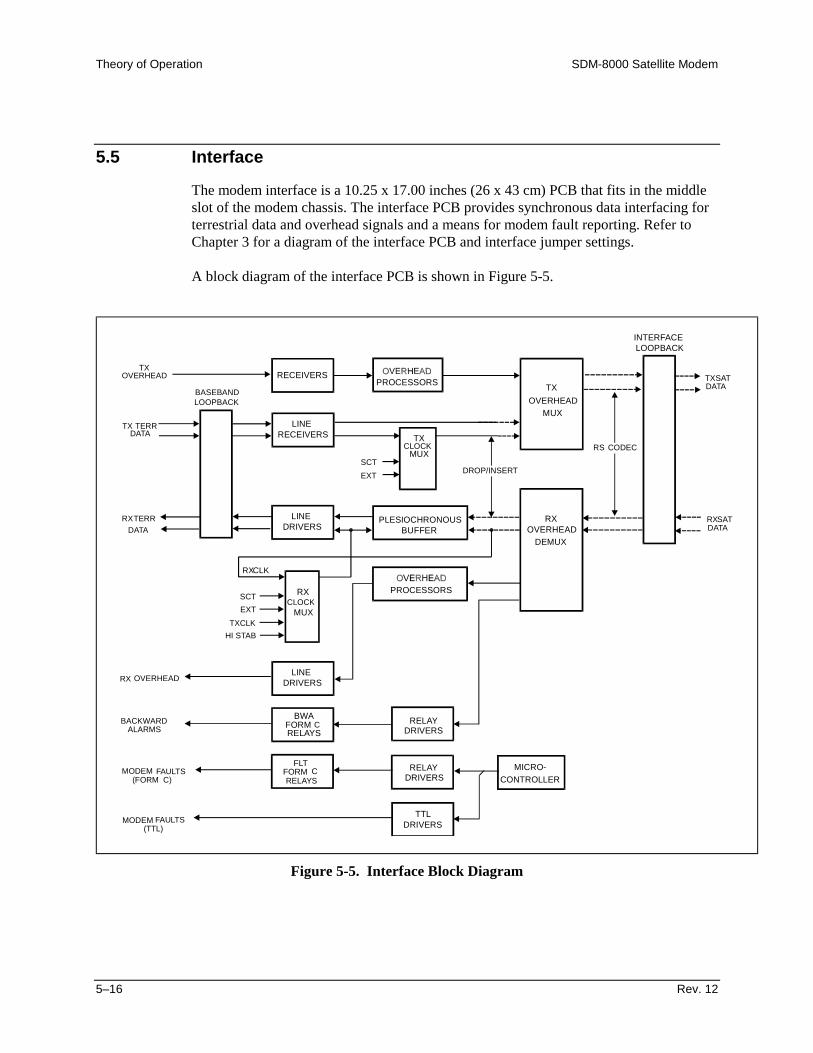
Theory of Operation SDM-8000 Satellite Modem
5–16 Rev. 12
5.5 Interface
The modem interface is a 10.25 x 17.00 inches (26 x 43 cm) PCB that fits in the middleslot of the modem chassis. The interface PCB provides synchronous data interfacing forterrestrial data and overhead signals and a means for modem fault reporting. Refer toChapter 3 for a diagram of the interface PCB and interface jumper settings.
A block diagram of the interface PCB is shown in Figure 5-5.
INTERFACE
BASEBANDLOOPBACK
TXOVERHEAD
TX TERR
RECEIVERS
LINE
PROCESSORS
OVERHEADMUX
TX
LOOPBACK
DATATXSAT
TXCLOCK
MUXSCTEXT
RECEIVERSDATA
DATARXTERR
RXCLOCK
RXCLK
PLESIOCHRONOUSBUFFER
PROCESSORS
OVERHEADDEMUX
RXDATARXSAT
MUX
SCTEXT
TXCLKHI STAB
RX OVERHEAD
BACKWARDALARMS
LINE
LINE
DRIVERS
DRIVERS
BWAFORM CRELAYS DRIVERS
RELAY
DRIVERSRELAY
DRIVERSTTL
FLTFORM CRELAYS
MODEM FAULTS
MODEM FAULTS
(FORM C)
(TTL)
MICRO-CONTROLLER
DROP/INSERT
RS CODEC
Figure 5-5. Interface Block Diagram

SDM-8000 Satellite Modem Theory of Operation
Rev. 12 5–17
The terrestrial interface functions include:
• Multiplexing various types of ESC into the data• Buffering the received data• Demultiplexing various types of ESC from the data• Monitoring and displaying the interface status without interruption of service
The interface PCB can be configured for the following closed and open network types ofmodem operation (Types 1 to 5):
Type Description1 Closed Network Only2 Closed Network Only with Buffer3 Open Network, IBS with Buffer4 Open Network, IBS, IDR with Buffer5 DVB
Overhead can be added to the terrestrial data for IBS and IDR modes of operation. Theformat of the overhead data is dependent on the mode of operation.
The interface supports terrestrial data rates from 9.6 kbit/s to 9.312 Mbit/s.
The terrestrial interfaces for the modem are defined by the data communication standardsMIL-STD-188/EIA-449, V.35, and G.703. The interface receivers and drivers for thesestandards, as well as the handshake signals for MIL-STD-188 and V.35, are selectablethrough multi-pin jumpers. Positions of the jumpers are monitored by the M&C todetermine if a selected configuration is valid.
The following four plug-on options can be used with the interface PCB:
• D&I multiplexer that works in conjunction with the interface PCB to enable themodem to transmit or receive fractional parts of a T1/E1 data stream(Appendix B).
• D&I with ASYNC overhead data channel which is typically used for earthstation-to-earth station communication (Appendix B)
• Reed-Solomon Codec that works in conjunction with the Viterbi decoder andincludes additional framing, interleaving, and Codec processing to provideconcatenated FEC and convolutional encoding and decoding (Appendix B).
• Interface relay board that provides the modem user with an easy method tochange the data interface. The interface relay replaces the need to physicallychange the multi-pin jumpers by enabling the selection of the data interfacesfrom the front panel.
Theory of Operation SDM-8000 Satellite Modem
5–18 Rev. 12
5.5.1 Interface Specifications
Refer to Appendix C for Interface specifications.
5.5.2 Theory of Operation
This section provides the theory of operation for closed and open network.
5.5.2.1 Closed Network
Closed network operation does not add overhead to the terrestrial data. The terrestrialdata and clock are passed through the baseband loopback relay and are translated fromthe selected baseband format to TTL. The data is resynchronized by the clock and thedata stream is then output to the modulator through the interface loopback device.
The receive data from the demodulator/decoder is input through the same interfaceloopback device. User data from the DEMUX section may be optionally input to aplesiochronous buffer.
The front panel interface provides five clock selections clocking the data out of thebuffer:
• Internal Clock (SCT)• RX Recovered Clock (RXCLK)• External Reference Clock (EXT)• High Stability Clock (HI STAB)• TX Clock Dejittered (TXCLK)
If either RXCLK or EXT is selected and then fails, the interface will automaticallyswitch to INT (SCT) as the source. The receive data and selected clock are translated tothe levels of the selected baseband interface and output through the baseband loopbackrelay.

SDM-8000 Satellite Modem Theory of Operation
Rev. 12 5–19
5.5.2.2 Open Network
The modem is a high-performance, full-duplex, digital-vector modulator/demodulator.The modem meets the open network requirements of the INTELSAT IESS-308, -309 and-310 specifications for IDR, IBS, and EUTELSAT SMS.
5.5.2.3 IDR
IDR operation adds 96 kbit/s overhead to the terrestrial data. The terrestrial data ratessupported are:
• 1.544 Mbit/s (T1)• 2.048 Mbit/s (E1)• 6.312 Mbit/s (T2)• 9.312 Mbit/s (E2)
The terrestrial data is passed through the baseband loopback relay and is translated fromthe G.703 format to TTL with a recovered clock.
Overhead framing, two ADPCM audio channels, four backward alarms, and an EIA-422format 8 kbit/s synchronous data channel are multiplexed with the dejittered terrestrialdata.
The interface for the audio is a 600Ω transformer-balanced input. The ADPCM audiochannels are encoded according to CCITT G.721.
The backward alarms are level-translated to TTL by threshold comparators set to 2.5V.A 1K pull-up resistor to +5V is connected to each alarm input.
The multiplexed data stream is output to the modulator through the interface loopbackdevice. The receive data from the demodulator is input through the same interfaceloopback device. The receive data is demultiplexed to produce:
• Receive Terrestrial Data• 2 ADPCM Audio Channels• 4 Backward Alarms• 8 kbit/s Synchronous Data Channel
The ADPCM audio channels are decoded according to CCITT G.721, and output througha 600Ω transformer.
The backward alarms are reported to the M&C and output to FORM C relay contacts.
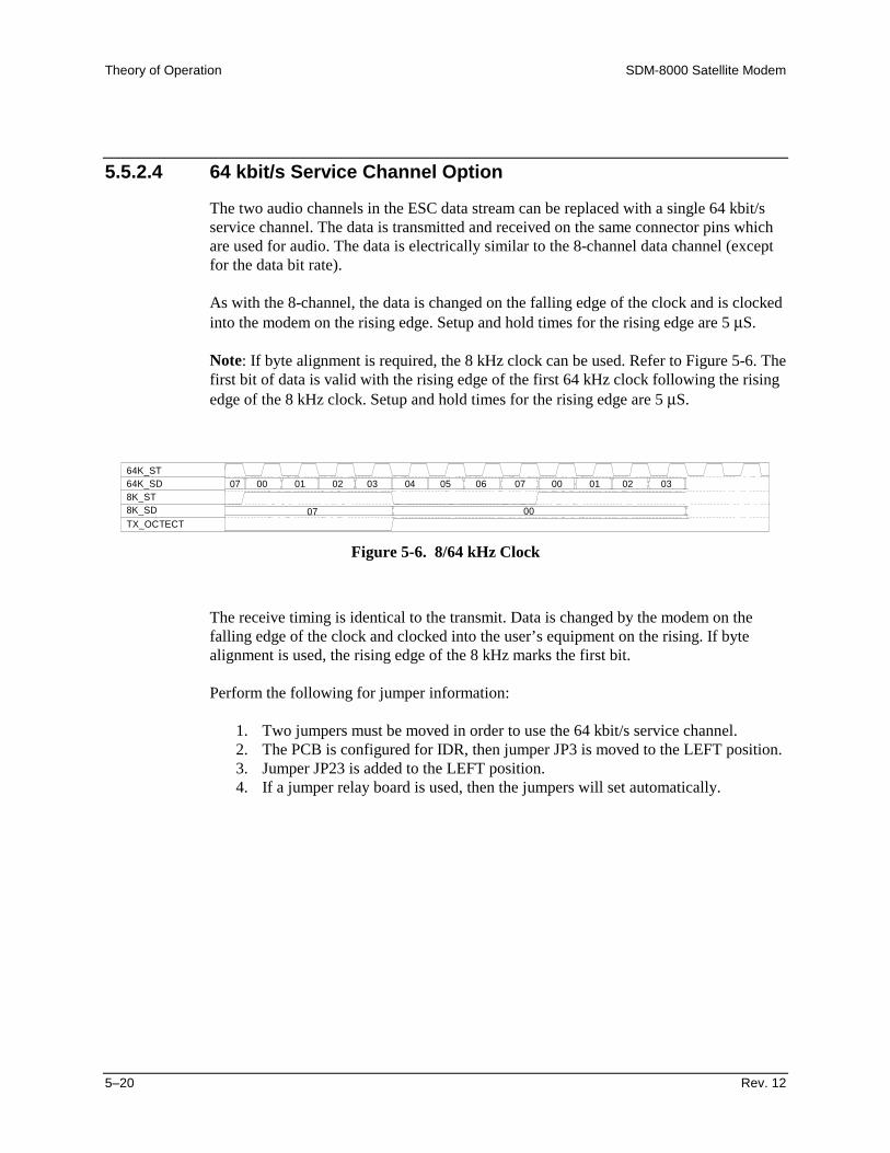
Theory of Operation SDM-8000 Satellite Modem
5–20 Rev. 12
5.5.2.4 64 kbit/s Service Channel Option
The two audio channels in the ESC data stream can be replaced with a single 64 kbit/sservice channel. The data is transmitted and received on the same connector pins whichare used for audio. The data is electrically similar to the 8-channel data channel (exceptfor the data bit rate).
As with the 8-channel, the data is changed on the falling edge of the clock and is clockedinto the modem on the rising edge. Setup and hold times for the rising edge are 5 µS.
Note: If byte alignment is required, the 8 kHz clock can be used. Refer to Figure 5-6. Thefirst bit of data is valid with the rising edge of the first 64 kHz clock following the risingedge of the 8 kHz clock. Setup and hold times for the rising edge are 5 µS.
64K_ST
07
078K_ST8K_SDTX_OCTECT
64K_SD
00
00 01 02 03 04 05 06 07 00 01 02 03
Figure 5-6. 8/64 kHz Clock
The receive timing is identical to the transmit. Data is changed by the modem on thefalling edge of the clock and clocked into the user’s equipment on the rising. If bytealignment is used, the rising edge of the 8 kHz marks the first bit.
Perform the following for jumper information:
1. Two jumpers must be moved in order to use the 64 kbit/s service channel.2. The PCB is configured for IDR, then jumper JP3 is moved to the LEFT position.3. Jumper JP23 is added to the LEFT position.4. If a jumper relay board is used, then the jumpers will set automatically.

SDM-8000 Satellite Modem Theory of Operation
Rev. 12 5–21
5.5.2.5 8 kbit/s Synchronous Data Channel
The 8 kbit/s synchronous data channel is formatted for EIA-422. The terrestrial dataoutput from the demultiplexer is input to a plesiochronous buffer. The front panelinterface provides four clock selections clocking the data out of the buffer:
• Internal Clock (SCT)• RX Recovered Clock (RXCLK)• External Reference Clock (EXT)• High Stability Clock (HI STAB)• TX Clock (TXCLK)
If either RXCLK or EXT is selected and then fails, the interface automatically switchesto INT (SCT) recovered clock as the source.
The AIS is detected in the receive data and reported to the M&C. The M&C controlinserts AIS into the TX data path. The receive data and selected clock are translated toconform to G.703 interface, and output through the baseband loopback relay.
Four sets of transmit and receive backward alarms are available to implement thestructure defined in IESS-308. Backward alarms are sent to the distant side of an IDRlink to signal that trouble has occurred at the receive side (which may have resulted froman improper transmission).
Implementation is straight forward in a simple, single destination link. INTELSATspecifies that any major failure of the downlink chain is to generate a backward alarm.The modem has a demodulator fault relay which de-energizes in the event of a receivefault.
The fault tree for this signal includes the appropriate overhead framing faults in order forthis relay to be connected to the appropriate backward alarm input. This signal alsoincludes faults in the downlink chain, since major problems with the antenna, Low NoiseAmplifier (LNA), down converter, and other components will cause an interruption inservice and fault the modem. Refer to Chapter 2 for connection information.

Theory of Operation SDM-8000 Satellite Modem
5–22 Rev. 12
5.5.2.6 IBS
IBS operation adds a proportional overhead (1/15) to the terrestrial data. The terrestrialdata and clock are passed through the baseband loopback relay and are translated fromthe selected baseband format to TTL. The data is scrambled synchronously with themultiframe sync in the multiplexer. The scrambler is enabled by the front panel.
External input and output for an ESC in EIA-232 format is provided on the interface. TheESC runs asynchronously at approximately 1/512 of the terrestrial data rate. If the ESCclock is not used, the channel runs at 1/2000 of the terrestrial data rate. The overheadcontaining framing, the ESC channel, and faults from the modem are multiplexed withdejittered terrestrial data. The multiplexed data stream is output to the modulator throughthe interface loopback device.
The receive data from the demodulator is input through the same interface loopbackdevice. The receive data is demultiplexed and synchronously descrambled by thedemultiplexer. The backward alarms are reported to the M&C and output by Form Crelay contacts. The ESC is output by an EIA-232 driver. The terrestrial data output fromthe demultiplexer is input to a plesiochronous buffer.
The front panel interface provides five clock selections clocking the data out of thebuffer:
• Internal Clock (SCT)• RX Recovered Clock (RXCLK)• External Reference Clock (EXT)• High Stability Clock (HI STAB)• TX Clock Dejittered (TXCLK)
If either RXCLK or EXT is selected and then fails, the interface automatically switchesto INT (SCT) as the source. AIS is detected in the receive data and reported to the M&C.The receive data and selected clock are translated to the levels of the selected basebandinterface and output through the baseband loopback relay.

SDM-8000 Satellite Modem Theory of Operation
Rev. 12 5–23
5.6 Backward Alarm Theory and Connections
Four sets of transmit and receive backward alarms are available to implement thestructure defined in IESS-308. Backward alarms are sent to the distant side of an IDRlink to signal that trouble has occurred at the receive side (which may have resulted froman improper transmission).
Implementation is straightforward in a simple, single destination link. INTELSATspecifies that any major failure of the downlink chain will generate a backward alarm.The modem has a demodulator fault relay which de-energizes in the event of a receivefault. For this relay to be connected to the appropriate backward alarm input, the faultmenu for this signal includes the appropriate overhead framing faults.
This signal also includes faults in the downlink chain, since major problems with theantenna, LNA, down converter, and other components will cause an interruption inservice and fault the modem.
The outputs of the demodulator fault relay are available as follows:
• Pins DF-C and DF-NO on the 50-pin D IDR interface connector (J8)• 9-pin D modem fault connector (J7)
The relay contacts are named for the faulted state. If a receive fault does not occur, DF-Cis connected to DF-NO.
The preferred method of using a backward alarm in a single destination system is toconnect the signals at the IDR data interface, either at the modem in a non-redundantsystem, or at the protection switch, if used.
Signal Pin #GND DB50-2BWI1 DB50-12BWI2 DB50-13BWI3 DB50-14BWI4 DB50-15DF-C DB50-16
DF-NO DB50-50
This method signals faults on all four alarm channels, and is compatible with aredundancy system. The method assumes that the same modem handles traffic in bothdirections in each single destination link.

Theory of Operation SDM-8000 Satellite Modem
5–24 Rev. 12
To handle more complicated systems, connect the appropriate outputs of the demod faultrelay to the appropriate backward alarm inputs. In a multidestination system, connect therelay to the particular backward alarm assigned to that link. Refer to IESS-308 for furtherclarification.
There are two methods for detecting a backward alarm that is being received on aparticular link. Each backward alarm output drives a FORM C relay with all threecontacts available on the data connector. If a modem (or switch) is integrated into acomputer network through the modem (or switch) EIA-232 or EIA-485 remote interfaceconnector, the status of all transmit and receive backward alarms may be read throughthat port. Refer to Appendix A for the remote interface specification.
In addition to the four backward alarms for IDR and two backward alarms (primary andsecondary) for IBS, all modes support the following faults:
• MOD (modulator equipment)• DEM (demodulator equipment)• CEQ (common equipment)
Each fault is indicated by a FORM C relay contact and an open collector output.

Rev. 12 6–1
6Chapter 6. MAINTENANCE
This chapter contains system checkout, fault isolation, and module replacementinformation.
6.1 System Checkout
This section provides instructions for checking the modem setup within the earth station.
Due to the complexity of the modem circuitry, use the checkout procedure only as abasic guideline. More complicated tests are beyond the scope of this manual.
The system checkout consists of test instructions for the modulator PCB, demodulatorPCB, and interface PCB. The instructions include tables and test points for ensuring thatthe Eb/N0, typical output spectrums, typical eye patterns, and constellation pictures arecorrect.
If a test failure occurs, refer to Section 6.2 for fault isolation procedures.
CAUTION
This equipment contains parts and assemblies sensitive to damage by ESD.Use ESD precautionary procedures when touching, removing, or insertsPCBs.
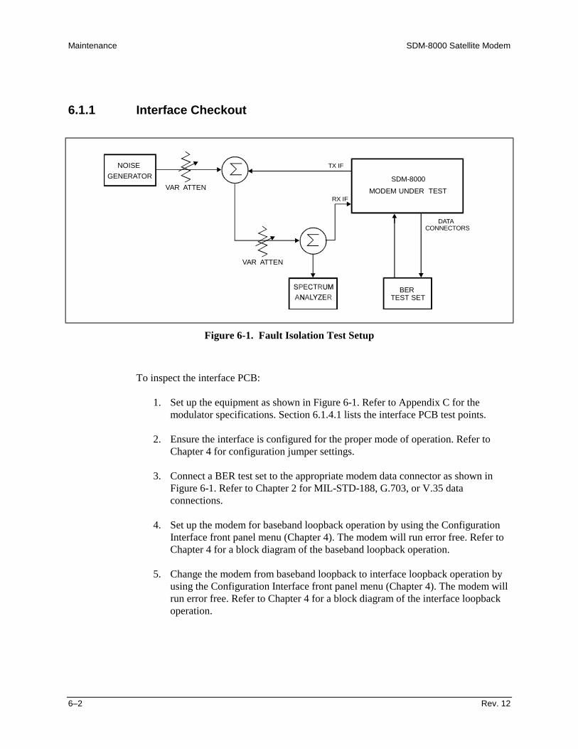
Maintenance SDM-8000 Satellite Modem
6–2 Rev. 12
6.1.1 Interface Checkout
SDM-8000
NOISEGENERATOR
ATTEN
ATTEN
VAR
VAR MODEM UNDER TEST
DATACONNECTORS
BERTEST SET
TX IF
RX IF
Figure 6-1. Fault Isolation Test Setup
To inspect the interface PCB:
1. Set up the equipment as shown in Figure 6-1. Refer to Appendix C for themodulator specifications. Section 6.1.4.1 lists the interface PCB test points.
2. Ensure the interface is configured for the proper mode of operation. Refer toChapter 4 for configuration jumper settings.
3. Connect a BER test set to the appropriate modem data connector as shown inFigure 6-1. Refer to Chapter 2 for MIL-STD-188, G.703, or V.35 dataconnections.
4. Set up the modem for baseband loopback operation by using the ConfigurationInterface front panel menu (Chapter 4). The modem will run error free. Refer toChapter 4 for a block diagram of the baseband loopback operation.
5. Change the modem from baseband loopback to interface loopback operation byusing the Configuration Interface front panel menu (Chapter 4). The modem willrun error free. Refer to Chapter 4 for a block diagram of the interface loopbackoperation.

SDM-8000 Satellite Modem Maintenance
Rev. 12 6–3
6.1.2 Modulator Checkout
To inspect the modulator PCB:
1. Set up the equipment as shown in Figure 6-1. Refer to Appendix C for themodulator specifications. Section 6.1.4.2 lists the modulator PCB test points andsignal names.
2. Set up the modem for IF loopback operation by using the ConfigurationDemodulator front panel menu (Chapter 4), or use an external IF loop withattenuation. Refer to Chapter 4 for a block diagram of the IF loopback operation.
3. Clear all TX faults by correct use of data and clock selection (Chapter 4).
4. Measure the Eb/N0 with a receiver that is known to be properly operating. Referto Table 6-1 and to check for proper Eb/N0 level. The (S+N)/N is measured bytaking the average level of the noise and the average level of the modemspectrum top. Use this measurement for the first column on Table 6-1. Readacross the page to find the S/N and Eb/N0 for the specific code rate.
Once the demodulator has locked to the incoming signal, the Monitor menu willdisplay signal level, raw BER, corrected BER, and Eb/N0.
Refer to Appendix C for examples of BER performance curves.
5. Connect a spectrum analyzer to the modem as shown Figure 6-2. Ensure the IFoutput meets the appropriate mask and spurious specifications. Measure thepower output at different levels and frequencies.
A typical output spectrum is shown in Figure 6-3.
6. To check the frequency and phase modulation accuracy:
a. Set the modem to the continuous wave Normal mode by using the CarrierMode front panel menu (Chapter 4). This sets the Carrier mode in the offcondition. A pure carrier should now be present at the IF output. Use thisonly for frequency measurements. Spurious and power measurements will beinaccurate.
b. Set the modem to the continuous wave Offset mode by using the CarrierMode front panel menu (Chapter 4). This generates a single upper side-bandsuppressed carrier signal. Ensure the carrier and side-band suppression is< -30 dBc.

Maintenance SDM-8000 Satellite Modem
6–4 Rev. 12
Table 6-1. Conversion to S/N and Eb/N0 Chart
(dB) Code Rate 1/2 Code Rate 3/4 Code Rate 7/8(S+N)/N S/N Eb/N0 S/N Eb/N0 S/N Eb/N0
4.0 1.8 1.8 1.8 0.0 1.8 -0.64.5 2.6 2.6 2.6 0.8 2.6 0.25.0 3.3 3.3 3.3 1.6 3.3 0.95.5 4.1 4.1 4.1 2.3 4.1 1.66.0 4.7 4.7 4.7 3.0 4.7 2.36.5 5.4 5.4 5.4 3.6 5.4 3.07.0 6.0 6.0 6.0 4.3 6.0 3.67.5 6.6 6.6 6.6 4.9 6.6 4.28.0 7.3 7.3 7.3 5.5 7.3 4.88.5 7.8 7.8 7.8 6.1 7.8 5.49.0 8.4 8.4 8.4 6.7 8.4 6.09.5 9.0 9.0 9.0 7.2 9.0 6.6
10.0 9.5 9.5 9.5 7.8 9.5 7.110.5 10.1 10.1 10.1 8.3 10.1 7.711.0 10.6 10.6 10.6 8.9 10.6 8.211.5 11.2 11.2 11.2 9.4 11.2 8.812.0 11.7 11.7 11.7 10.0 11.7 9.312.5 12.2 12.2 12.2 10.5 12.2 9.813.0 12.8 12.8 12.8 11.0 12.8 10.313.5 13.3 13.3 13.3 11.5 13.3 10.914.0 13.8 13.8 13.8 12.1 13.8 11.414.5 14.3 14.3 14.3 12.6 14.3 11.915.0 14.9 14.9 14.9 13.1 14.9 12.415.5 15.4 15.4 15.4 13.6 15.4 12.916.0 15.9 15.9 15.9 14.1 15.9 13.516.5 16.4 16.4 16.4 14.6 16.4 14.017.0 16.9 16.9 16.9 15.2 16.9 14.517.5 17.4 17.4 17.4 15.7 17.4 15.018.0 17.9 17.9 17.9 16.2 17.9 15.518.5 18.4 18.4 18.4 16.7 18.4 16.019.0 18.9 18.9 18.9 17.2 18.9 16.519.5 19.5 19.5 19.5 17.7 19.5 17.020.0 20.0 20.0 20.0 18.2 20.0 17.5

SDM-8000 Satellite Modem Maintenance
Rev. 12 6–5
ATTEN 10 dB2.00 dB/DIV
RES BANDWIDTH10.0 kHz
RL -49.00 dBm
CENTER 70.000 MHz*RB 10.0 kHz *VB 10.0 Hz
SPAN 1.000 MHzST 30.00 sec
Modem Rate = 2144kbit/s, 3/4 Rate Codingwith 7.7 dB Eb/No (S + N)/N = 10 dB
Figure 6-2. Typical Output Spectrum (with Noise)
ATTEN 10 dB5.00 dB/DIV
CENTER FREQUENCY140.000 MHz
RL -20.29 dBm
PASS
CENTER 140.000 MHz*RB 30.0 kHz *VB 3.00 Hz
SPAN 5.000 MHzST 166.7 sec
Figure 6-3. Typical Output Spectrum
Maintenance SDM-8000 Satellite Modem
6–6 Rev. 12
6.1.3 Demodulator Checkout
To inspect the demodulator PCB.
1. Set up the equipment as shown in Figure 6-1. Refer to Appendix C for thedemodulator specifications. Section 6.1.4.3 lists the demodulator PCB test pointsand signal names.
2. Set up the modem with an external IF loop, and level. Using a properly operatingmodulator, ensure that power levels, data rates, code rates, etc. are compatible.
3. Allow the modem to lock up. Depending on the data rate and overhead type,lockup may take several minutes.
a. When the green Carrier Detect LED is on and the DEMUX lock fault hasbeen cleared (where applicable), the modem will run at the specified errorrate.
b. Run the TX power level (input amplitude) over the full range, and offset theTX frequency from the RX frequency by 30 kHz. Ensure the modem stillruns within the specified error rate.
4. Set up the modem to check the constellation patterns with an oscilloscope that isset in the X-Y mode. Figure 6-4 shows typical constellation patterns with noiseand without noise.

SDM-8000 Satellite Modem Maintenance
Rev. 12 6–7
WITH NOISE
WITHOUT NOISE
Figure 6-4. Typical Eye Constellations
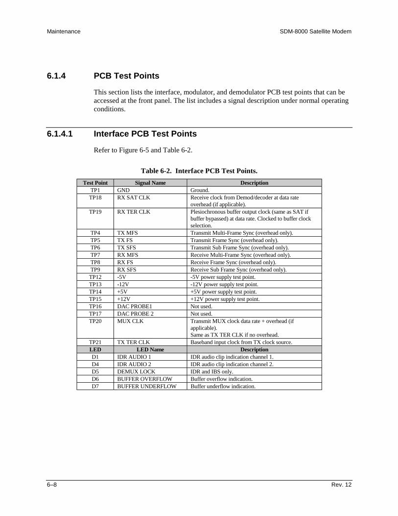
Maintenance SDM-8000 Satellite Modem
6–8 Rev. 12
6.1.4 PCB Test Points
This section lists the interface, modulator, and demodulator PCB test points that can beaccessed at the front panel. The list includes a signal description under normal operatingconditions.
6.1.4.1 Interface PCB Test Points
Refer to Figure 6-5 and Table 6-2.
Table 6-2. Interface PCB Test Points.Test Point Signal Name Description
TP1 GND Ground.TP18 RX SAT CLK Receive clock from Demod/decoder at data rate
overhead (if applicable).TP19 RX TER CLK Plesiochronous buffer output clock (same as SAT if
buffer bypassed) at data rate. Clocked to buffer clockselection.
TP4 TX MFS Transmit Multi-Frame Sync (overhead only).TP5 TX FS Transmit Frame Sync (overhead only).TP6 TX SFS Transmit Sub Frame Sync (overhead only).TP7 RX MFS Receive Multi-Frame Sync (overhead only).TP8 RX FS Receive Frame Sync (overhead only).TP9 RX SFS Receive Sub Frame Sync (overhead only).
TP12 -5V -5V power supply test point.TP13 -12V -12V power supply test point.TP14 +5V +5V power supply test point.TP15 +12V +12V power supply test point.TP16 DAC PROBE1 Not used.TP17 DAC PROBE 2 Not used.TP20 MUX CLK Transmit MUX clock data rate + overhead (if
applicable).Same as TX TER CLK if no overhead.
TP21 TX TER CLK Baseband input clock from TX clock source.LED LED Name DescriptionD1 IDR AUDIO 1 IDR audio clip indication channel 1.D4 IDR AUDIO 2 IDR audio clip indication channel 2.D5 DEMUX LOCK IDR and IBS only.D6 BUFFER OVERFLOW Buffer overflow indication.D7 BUFFER UNDERFLOW Buffer underflow indication.
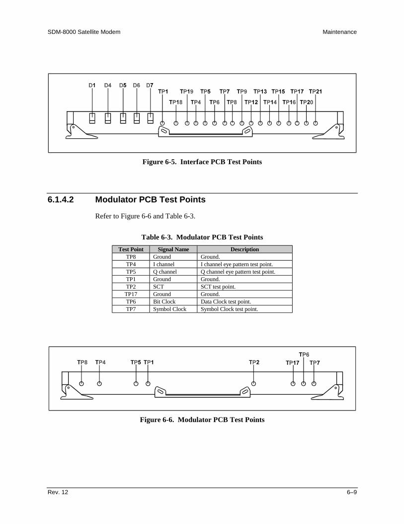
SDM-8000 Satellite Modem Maintenance
Rev. 12 6–9
Figure 6-5. Interface PCB Test Points
6.1.4.2 Modulator PCB Test Points
Refer to Figure 6-6 and Table 6-3.
Table 6-3. Modulator PCB Test PointsTest Point Signal Name Description
TP8 Ground Ground.TP4 I channel I channel eye pattern test point.TP5 Q channel Q channel eye pattern test point.TP1 Ground Ground.TP2 SCT SCT test point.
TP17 Ground Ground.TP6 Bit Clock Data Clock test point.TP7 Symbol Clock Symbol Clock test point.
Figure 6-6. Modulator PCB Test Points

Maintenance SDM-8000 Satellite Modem
6–10 Rev. 12
6.1.4.3 Demodulator PCB Test Points
Refer to Figure 6-7 and Table 6-4.
Table 6-4. Demodulator PCB Test PointsTest Point Signal Name Description
TP25 SYMBOL CLK Symbol clock.TP21 GND Ground test point.TP5 Q EYE Q channel monitor. The I and Q test points are a digital
representation of the received filtered signal. To view these testpoints, use an oscilloscope in the X-Y mode. The display will bethe constellation shown in Figure 6-4.
TP6 I EYE I channel monitor. See Q EYE test point.TP20 GND Ground test point.TP18 HS BUF CLK High-stability buffer clock (optional feature).TP15 DATA CLK Data Clock.
Figure 6-7. Demodulator PCB Test Points
SDM-8000 Satellite Modem Maintenance
Rev. 12 6–11
6.2 Fault Isolation
The modem’s design allows a competent technician to repair a faulty modem on location.All active circuits, except the power supply, can be removed from the modem throughthe front panel, without requiring special tools. The power supply can be removedthrough the top cover with standard tools.
CAUTION
This equipment contains parts and assemblies sensitive to damage by ESD.Use ESD precautionary procedures when touching, removing, or insertsPCBs.
The fault monitoring capability of the modem assists the operator in determining whichPCB has failed. Replace the faulty PCB with a working spare. Return the faulty PCB toComtech EFData for repair.
The fault isolation procedure lists the following categories of faults or alarms:
• Modulator• Demodulator• Transmit Interface• Receive Interface• Common Equipment• Backward Alarms
Note: Each fault or alarm category listed in Section 6.2.3 includes possible problems andthe appropriate action required to repair the modem.
If any of the troubleshooting procedures mentioned in this chapter do not isolate theproblem, and Comtech EFData Customer Service assistance is necessary, have thefollowing information available for the representative:
• Modem configuration. Modem configuration includes the modulator,demodulator, interface, and local AUPC sections.
• Faults (active or stored).
6.2.1 System Faults/Alarms
System faults are reported in the Faults/Alarms menu, and stored faults are reported inthe Stored Flts/Alms menu. Refer to Chapter 4 for more information. To determine theappropriate actions for repairing the modem, refer to Table 6-5 and the list of possibleproblems and actions in Section 6.2.3.

Maintenance SDM-8000 Satellite Modem
6–12 Rev. 12
Table 6-5. SDM-8000 Fault Tree
MODULATOR FAULTS
TX
IF
OUTPUT
OFF
TX
FAULT
LED
TX
FAULT
RELAY
(1)
RX
FAULT
LED
RX
FAULT
RELAY
(2)
COM
EQ
FAULT
LED
COM
EQ
FAULT
RELAY
(3)
TX
ALARM
LED
TX
ALARM
RELAY
#2
(4)
RX
ALARM
LED
RX
ALARM
RELAY
#3
(5)
SPARE
RELAY
ALARM
#1
PRI
MARY
ALARM
RELAY
(6)*****
SECONDARY
ALARM
RELAY
(7)*****
IBS
BACKWARD
ALARM
*****
DEFERRED
MAIN
ALARM
(8)*
TX
AIS
******
RX
AIS
******
D&I
TERR
BWA
***
IF SYNTHESIZER X X X X X XDATA CLOCK ACT X X X XDATA CLOCK SYN X X X X X XI CHANNEL X X X X X XQ CHANNEL X X X X X XAGC X X X X X XINTERNAL SCT SYN X X X X X XEXT REF ACT X X X XMODULE X X X X X XPROGRAMMING X X X X X XCONFIGURATION X X X X X X
DEMODULATOR FAULTSCARRIER DETECT X X X X XIF SYNTHESIZER X X X X XRX CLOCK SYN X X X X XI CHANNEL X X X X XQ CHANNEL X X X X XDESCRAMBLER X X XBER THRESHOLD X X X XMODULE X X X X XPROGRAMMING X X X X XCONFIGURATION X X X X X
LegendTest Note Fault/Alarm Relay Test Points Connector/Pins
1 TX FAULT J4/Pin 4 (NO), 5 (COM), 6 (NC) ****2 RX FAULT J4/Pin 7 (NO), 8 (COM), 9 (NC) ****3 COM EQ FAULT J4/Pin 1 (NO), 2 (COM), 3 (NC) ****4 TX ALARM #2 J10/Pin 4 (NO), 5 (COM), 6 (NC) ****5 RX ALARM #3 J10/Pin 7 (NO), 8 (COM), 9 (NC) ****6 PROMPT ALARM J5/Pin 43 (NO), 10 (COM), 27 (NC) ****7 SERVICE ALARM J5/Pin 44 (NO), 11 (COM), 28 (NC) ****8 DEF MAINT ALARM J5/Pin 17 *****
* IDR only** IBS only*** D&I only**** A connection between the common and N.O. contacts indicates no fault/alarm.**** Signal is open collector high impedance if faulted.
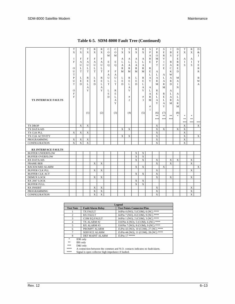
SDM-8000 Satellite Modem Maintenance
Rev. 12 6–13
Table 6-5. SDM-8000 Fault Tree (Continued)
TX INTERFACE FAULTS
TX
IF
OUTPUT
OFF
TX
FAULT
LED
TX
FAULT
RELAY
(1)
RX
FAULT
LED
RX
FAULT
RELAY
(2)
COM
EQ
FAULT
LED
COM
EQ
FAULT
RELAY
(3)
TX
ALARM
LED
TX
ALARM
RELAY
#2
(4)
RX
ALARM
LED
RX
ALARM
RELAY
#3
(5)
SPARE
RELAY
ALARM
#1
PROMPT
ALARM
RELAY
(6)*****
SERVICE
ALARM
RELAY
(7)*****
IBS
BACKWARD
ALARM
*****
DEFERRED
MAIN
ALARM
(8)*
TX
AIS
******
RX
AIS
******
D&I
TERR
BWA
***TX DROP X X X X XTX DATA/AIS X X X X X XTX CLK PLL X X X X XTX CLK ACTIVITY X X X X XPROGRAMMING X X X X XCONFIGURATION X X X X X
RX INTERFACE FAULTSBUFFER UNDERFLOW X XBUFFER OVERFLOW X XRX DATA/AIS X X X X X XFRAME BER X X X X XBACKWARD ALARM X X X XBUFFER CLK PLL X X X XBUFFER CLK ACT X X XDEMUX LOCK X X X X XRX 2047 LOCK X XBUFFER FULL X XRX INSERT X X X XPROGRAMMING X X X XCONFIGURATION X X X X
LegendTest Note Fault/Alarm Relay Test Points Connector/Pins
1 TX FAULT J4/Pin 4 (NO), 5 (COM), 6 (NC) ****2 RX FAULT J4/Pin 7 (NO), 8 (COM), 9 (NC) ****3 COM EQ FAULT J4/Pin 1 (NO), 2 (COM), 3 (NC) ****4 TX ALARM #2 J10/Pin 4 (NO), 5 (COM), 6 (NC) ****5 RX ALARM #3 J10/Pin 7 (NO), 8 (COM), 9 (NC) ****6 PROMPT ALARM J5/Pin 43 (NO), 10 (COM), 27 (NC) ****7 SERVICE ALARM J5/Pin 44 (NO), 11 (COM), 28 (NC) ****8 DEF MAINT ALARM J5/Pin 17 *****
* IDR only** IBS only*** D&I only**** A connection between the common and N.O. contacts indicates no fault/alarm.**** Signal is open collector high impedance if faulted.

Maintenance SDM-8000 Satellite Modem
6–14 Rev. 12
Table 6-5. SDM-8000 Fault Tree (Continued)
COMMON EQUIP FAULTS
TX
IF
OUTPUT
OFF
TX
FAULT
LED
TX
FAULT
RELAY
(1)
RX
FAULT
LED
RX
FAULT
RELAY
(2)
COM
EQ
FAULT
LED
COM
EQ
FAULT
RELAY
(3)
TX
ALARM
LED
TX
ALARM
RELAY
#2
(4)
RX
ALARM
LED
RX
ALARM
RELAY
#3
(5)
SPARE
RELAY
ALARM
#1
PROMPT
ALARM
RELAY
(6)*****
SERVICE
ALARM
RELAY
(7)*****
IBS
BACKWARD
ALARM
*****
DEFERRED
MAIN
ALARM
(8)*
TX
AIS
******
RX
AIS
******
D&I
TERR
BWA
***BATTERY/CLOCK X X X-12V POWER SUPPLY X X X+12V POWER SUPPLY X X X+5V SUPPLY X X X-5V SUPPLY X X XCONTROLLER X X X X XINTERFACE MODULE X X X X X
BACKWARD ALARMS(IDR AND CUSTOM ONLY)
BW ALARM RX #4 X X XBW ALARM RX #3 X X XBW ALARM RX #2 X X XBW ALARM RX #1 X X XBW ALARM TX #4 X XBW ALARM TX #3 X XBW ALARM TX #2 X XBW ALARM TX #1 X X
LegendTest Note Fault/Alarm Relay Test Points Connector/Pins
1 TX FAULT J4/Pin 4 (NO), 5 (COM), 6 (NC) ****2 RX FAULT J4/Pin 7 (NO), 8 (COM), 9 (NC) ****3 COM EQ FAULT J4/Pin 1 (NO), 2 (COM), 3 (NC) ****4 TX ALARM #2 J10/Pin 4 (NO), 5 (COM), 6 (NC) ****5 RX ALARM #3 J10/Pin 7 (NO), 8 (COM), 9 (NC) ****6 PROMPT ALARM J5/Pin 43 (NO), 10 (COM), 27 (NC) ****7 SERVICE ALARM J5/Pin 44 (NO), 11 (COM), 28 (NC) ****8 DEF MAINT ALARM J5/Pin 17 *****
* IDR only** IBS only*** D&I only**** A connection between the common and N.O. contacts indicates no fault/alarm.**** Signal is open collector high impedance if faulted.
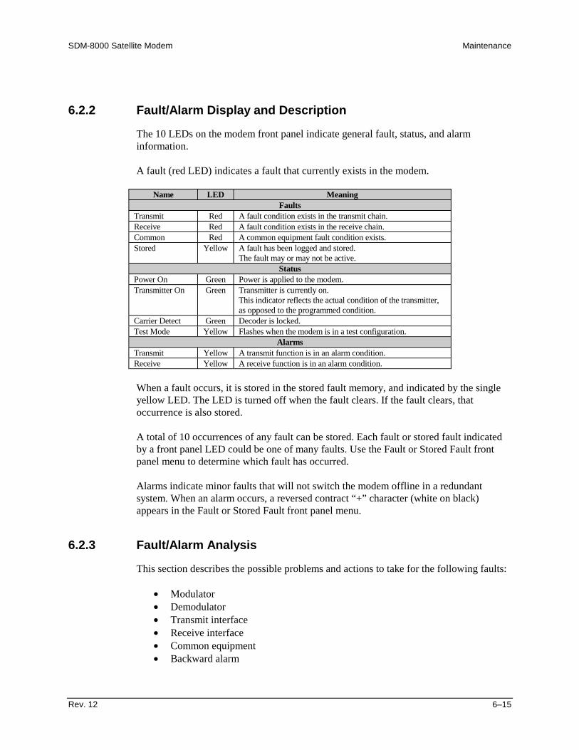
SDM-8000 Satellite Modem Maintenance
Rev. 12 6–15
6.2.2 Fault/Alarm Display and Description
The 10 LEDs on the modem front panel indicate general fault, status, and alarminformation.
A fault (red LED) indicates a fault that currently exists in the modem.
Name LED MeaningFaults
Transmit Red A fault condition exists in the transmit chain.Receive Red A fault condition exists in the receive chain.Common Red A common equipment fault condition exists.Stored Yellow A fault has been logged and stored.
The fault may or may not be active.Status
Power On Green Power is applied to the modem.Transmitter On Green Transmitter is currently on.
This indicator reflects the actual condition of the transmitter,as opposed to the programmed condition.
Carrier Detect Green Decoder is locked.Test Mode Yellow Flashes when the modem is in a test configuration.
AlarmsTransmit Yellow A transmit function is in an alarm condition.Receive Yellow A receive function is in an alarm condition.
When a fault occurs, it is stored in the stored fault memory, and indicated by the singleyellow LED. The LED is turned off when the fault clears. If the fault clears, thatoccurrence is also stored.
A total of 10 occurrences of any fault can be stored. Each fault or stored fault indicatedby a front panel LED could be one of many faults. Use the Fault or Stored Fault frontpanel menu to determine which fault has occurred.
Alarms indicate minor faults that will not switch the modem offline in a redundantsystem. When an alarm occurs, a reversed contract “+” character (white on black)appears in the Fault or Stored Fault front panel menu.
6.2.3 Fault/Alarm Analysis
This section describes the possible problems and actions to take for the following faults:
• Modulator• Demodulator• Transmit interface• Receive interface• Common equipment• Backward alarm

Maintenance SDM-8000 Satellite Modem
6–16 Rev. 12
6.2.3.1 Modulator Faults
Refer Table 6-6 to for modulator faults.
Table 6-6. Modulator FaultsFault/Alarm Possible Problem and Action
IF SYNTHESIZER Modulator IF synthesizer is faulted.
This is a major alarm, and will turn off the modulator output. Return themodulator for repair.
DATA CLOCK ACT Transmit data clock activity alarm.
This fault is not a major alarm and will not turn off the modulator output. Theproblem is most likely on the interface card or external to the modem. Use thebaseband loopback and interface loopback test modes for checking theinterface. Ensure the incoming data clock is present at the modem DATA I/Oconnector. If data and clock are present at the DATA I/O, then replace theinterface card to clear the fault and return the modem for repair.
DATA CLOCK SYN Transmit data clock synthesizer fault.
This fault is an indication that the internal clock VCO has not locked to theincoming data clock, or the internal clock synthesizer has not locked to theinternal reference. This is a major alarm, and will turn off the modulator output.Ensure the proper data rate has been set up and selected, and the incoming datarate matches the modem selections.
In the IDR type configuration, the data rate must reflect any overhead bits thatare added. In the IBS type, the internal reference is changed to account for theIBS overhead of 16/15. A standard IDR type configuration operating at Rev. 2would be programmed to the input data rate. An IBS type operating at Rev. 3would be programmed to reflect the 96 kbit/s of overhead. A 1544 kbit/s Rev. 3IDR is programmed to 1640 kbit/s. An IBS type would be programmed for theinput data rate to the channel unit. The modem accounts for the overheadbecause of the change in internal reference. Use interface loopback for isolatingthe problem. Verify the frequency of the input data clock to be within the lockrange of 100 PPM. If the inputs to the modem are correct, then the problemcould be in one of two locations. Check the modulator first by replacing it witha spare. If the problem still exists, replace the interface card. When the fault hasbeen isolated to a single card, send that card back for repair.
I CHANNEL Activity alarm for the I channel digital filter.
This alarm is considered a major alarm, and will turn off the modulator IFoutput. An alarm in this position indicates either a fault in the scrambler, or ifthe scrambler is disabled, it indicates a loss of incoming data. If the fault isactive with the scrambler turned off, check for input data at the DATA I/Oconnector. If data is present, replace the interface card to clear the fault andreturn the interface card for repair. If the fault is active with the scramblerturned on, replace the modulator card and return it for repair.

SDM-8000 Satellite Modem Maintenance
Rev. 12 6–17
Table 6-6. Modulator Faults (Continued)Q CHANNEL Activity alarm for the Q channel digital filter. Use the I channel procedure
above.AGC LEVEL Output power AGC level fault.
Indicates the level of the modulator output is not at the programmed level.Replace the modulator card and return it for repair.
INTERNAL SCT SYN Internal TX data clock synthesizer fault.
The SCT has failed to lock to the internal reference. Replace the modulatorboard.
EXT REF ACT External reference activity. Activity fault for the external reference clock.Indicates clock reference not detected.
MODULE Modulator module fault.
Typically indicates that the modulator module is missing or will not program.Ensure the modulator card is present and is properly seated. If the modulatorcard is properly seated, this could indicate a problem in the M&C card or in theinterface between the modulator and the M&C card. Another possible problemis the modulator firmware may be installed incorrectly or has a pin not makingcontact. Ensure the modulator firmware is correctly installed. Return thedefective card for repair.
PROGRAMMING Modulator programming fault.
Indicates the modulator module has failed to program a current configurationparameter. If this fault occurs, notify the factory for assistance.
CONFIGURATION Modulator configuration fault.
Indicates the modulator module does not support a programmed configurationparameter. This fault typically happens in the Custom mode when theprogrammed configuration does not match the module hardware. Verify theprogramming of the modulator hardware matches the configuration parameters.Also verify all jumpers are set correctly for currently programmedconfiguration parameters.
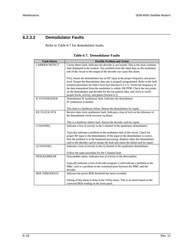
Maintenance SDM-8000 Satellite Modem
6–18 Rev. 12
6.2.3.2 Demodulator Faults
Refer to Table 6-7 for demodulator faults.
Table 6-7. Demodulator FaultsFault/Alarm Possible Problem and Action
CARRIER DETECT Carrier detect fault. Indicates the decoder is not locked. This is the most commonfault displayed in the modem. Any problem from the input data on the modulatorend of the circuit to the output of the decoder can cause this alarm.
First, ensure the demodulator has an RF input at the proper frequency and powerlevel. Ensure the demodulator data rate is properly programmed. Refer to the faultisolation procedure for Data Clock Syn (Section 6.2.3.1). Verify the frequency ofthe data transmitted from the modulator is within 100 PPM. Check the test pointson the demodulator and decoder for the eye pattern, data, and clock to verifyproper levels, activity, and phase (Section 6.1).
IF SYNTHESIZER Demodulator IF synthesizer fault. Indicates the demodulatorIF synthesizer is faulted.
This fault is a hardware failure. Return the demodulator for repair.RX CLOCK SYN Receive data clock synthesizer fault. Indicates a loss of lock on the reference of
the demodulator clock recovery oscillator.
This is a hardware failure fault. Return the decoder card for repair.I CHANNEL Indicates a loss of activity in the I channel of the quadrature demodulator.
Typically indicates a problem in the modulator side of the circuit. Check forproper RF input to the demodulator. If the input to the demodulator is correct,then the problem is in the baseband processing. Replace either the demodulatorcard or the decoder card to isolate the fault and return the failed card for repair.
Q CHANNEL Indicates a loss of activity in the Q channel of the quadrature demodulator.
Follow the same procedure for the I channel fault.DESCRAMBLER Descrambler alarm. Indicates loss of activity in the descrambler.
Typically indicates a loss of decoder program. Could indicate a problem in theM&C card or a problem in the communication between the M&C and thedecoder.
BER THRESHOLD Indicates the preset BER threshold has been exceeded.
Setting of this alarm is done in the Utility menu. This is an alarm based on thecorrected BER reading on the front panel.

SDM-8000 Satellite Modem Maintenance
Rev. 12 6–19
Table 6-7. Demodulator Faults (Continued)MODULE Demodulator module fault.
Typically indicates that the demodulator module is missing or will not program.Ensure the demodulator card is present and properly seated. If the card is properlyseated this could indicate a problem in the M&C card or in the interface betweenthe demodulator card and the M&C card. Return the defective card for repair.
PROGRAMMING Demodulator programming fault. Indicates the demodulator module has failed toprogram a current configuration parameter.
If this fault occurs, notify the factory for assistance.CONFIGURATION Demodulator configuration fault. Indicates the demodulator module does not
support a programmed configuration parameter.
This fault typically happens in the Custom mode when the programmedconfiguration does not match the module hardware. Verify the programming ofthe demodulator hardware matches the configuration parameters. Also verify alljumpers have been set correctly for currently programmed configurationparameters.

Maintenance SDM-8000 Satellite Modem
6–20 Rev. 12
6.2.3.3 Transmit Interface Faults
Refer to Table 6-8 for transmit interface faults.
Table 6-8. Transmit Interface FaultsFault/Alarm Possible Problem and Action
TX DROP Drop interface hardware fault (D&I only).
The typical cause of this fault is the drop phase-locked loop is not locked, or someother drop interface hardware has malfunctioned. Return the D&I card to thefactory for repair.
TX DATA/AIS Data or incoming AIS.
When the AIS is selected in the Interface Utility menu for TX data fault, thetransmit interface fault TX data/AIS is monitoring a fault condition of all 1s fromcustomer data input to the modem. When data is selected in the Interface Utilitymenu for TX data fault, the TX interface fault TX data/AIS is monitoring a faultcondition of all 1s or all 0s. This is referred to as a data stable condition (the data isnot transitioning). This fault indicates there is trouble in the chain sending data tothe modem. The modem passes this signal transparently and takes no other action.This indication is a monitor function only and aids in isolating the trouble source ina system.
TX CLOCK PLL Transmitter phase locked loop fault. Indicates the transmitterPLL is not locked to the reference of the interface transmit clock recoveryoscillator.
Return the interface card for repair.TX CLOCK ACT Activity detector alarm of the selected interface transmit clock. Indicates the
selected TX clock is not being detected.
Check the signal of the selected TX clock source to verify the signal is present. Theinterface will fall back to the internal clock when this alarm is active.
PROGRAMMING Transmit interface programming fault.
Indicates the TX interface module has failed to program a current configurationparameter. If this fault occurs, notify the factory for assistance.
CONFIGURATION Transmit interface configuration fault. Indicates the TX interface module does notsupport a programmed configuration parameter.
This fault typically happens in the Custom mode when the programmedconfiguration does not match the module hardware. Verify the programming of theTX interface hardware matches the configuration parameters. Also verify alljumpers have been set correctly for currently programmed configurationparameters.

SDM-8000 Satellite Modem Maintenance
Rev. 12 6–21
6.2.3.4 Receive Interface Faults
Refer to Table 6-9 for receive interface faults.
Table 6-9. Receive Interface FaultsFault/Alarm Possible Problem and Action
BUFFER UNDERFLOW Buffer underflow alarm. Indicates the plesiochronous buffer hasunderflowed.
Buffer underflow is normally a momentary fault (there are clock problems ifthis is continuously present). This is included in this section to be consistentwith the fault reporting system and correctly registered in the stored faultmemory. The time and date of the last 10 receive buffer underflow faults arestored in battery-backed memory as an aid to troubleshooting. The intervalbetween stored overflow/underflow events can be used to determine relativeclock accuracy’s.
BUFFER OVERFLOW Buffer overflow alarm. Indicates the plesiochronous buffer has overflowed.
The problems and actions in the buffer underflow section apply to thisalarm.
RX DATA/AIS Data or incoming AIS. The data monitored for RX data is coming from thesatellite.
When the AIS is selected for RX data fault in the Interface Utility menu, theRX data/AIS is monitoring an alarm condition of all 1s from the satellite.When DATA is selected for RX data fault in the Interface Utility menu, theRX data/AIS is monitoring a fault condition of all 1s or all 0s. This isreferred to as a data stable condition (meaning the data is not transitioning).The fault indicates trouble in receiving data from the satellite. The modempasses this signal transparently and can close a FORM C contact. Theindication is a monitor function only to help isolate the source of trouble in asystem.
FRAME BER The receive decoded error rate has exceeded 10E-3 over a 60-second periodmeasured on the framing bits.
This is defined as a major (prompt) receive alarm by INTELSATspecifications IESS-308. In a redundant system, a switch over will beattempted. Since some data must be correctly received to indicate this fault,receive AIS will not be substituted. This fault is to be sent as a backwardalarm to the distant end. This must be wired externally as faults other thanfrom the modem may need to enter the fault tree.
BACKWARD ALARM Backward alarm. Modem is receiving a backward alarm indicating trouble atthe distant end which may be a result of improper transmission at the nearend of the link.
This particular alarm is reported and recorded but the modem takes no otheraction. In most cases, the fault is due to some receive problem with themodem so a real fault will probably be occurring if backward alarm faultsare being recorded.

Maintenance SDM-8000 Satellite Modem
6–22 Rev. 12
Table 6-9. Receive Interface Faults (Continued)BUFFER CLK PLL Buffer clock phase-locked-loop fault. The buffer synthesizer is the wrong
frequency or will not lock.
Ensure the selected buffer clock source is at the proper frequency and level.If the fault continues, return the interface card for repair.
BUFFER CLK ACT Activity detector alarm of the selected interface receive clock.
The interface will fall back to the satellite clock when this fault is active.DEMUX_LOCK Demultiplexer synchronization lock fault. This fault means that the
demultiplexer is unable to maintain valid frame and multiframe alignment.
The usual cause is invalid or absent receive data. This is a major (prompt)alarm. It will cause insertion of receive AIS (all 1s) and the switch over willbe attempted. This fault is to be sent as a backward alarm to the distant end.This fault will occur when no carrier is present, but will probably neveroccur with a correct signal.
RX 2047 LOCK RX 2047 lock alarm. Indicates the RX 2047 data test pattern is not beingreceived by the decoder.
This probably indicates the transmitter is not set correctly.BUFFER FULL Buffer full alarm. Indicates the buffer is less than 10% or greater than 90%
full.RX INSERT Insert interface hardware fault (D&I only).
The typical cause of this fault is the insert phase locked loop is not locked orsome other insert interface hardware has malfunctioned. Return the D&Icard to the factory for repair.
PROGRAMMING Receive interface programming fault. Indicates the RX interface module hasfailed to program a current configuration parameter.
If this fault occurs, contact the Comtech EFData Customer ServiceDepartment.
CONFIGURATION Receive interface configuration fault. Indicates the RX interface moduledoes not support a programmed configuration parameter.
This fault typically happens in the Custom mode when the programmedconfiguration does not match the module hardware. Ensure theprogramming of the RX interface hardware matches the configurationparameters. Also verify all jumpers have been set correctly for currentlyprogrammed configuration parameters.

SDM-8000 Satellite Modem Maintenance
Rev. 12 6–23
6.2.3.5 Common Equipment Faults
Refer to Table 6-10 for common equipment faults.
Table 6-10. Common Equipment FaultsFault/Alarm Possible Problem and Action
BATTERY/CLOCK M&C battery voltage or clock fault. Indicates a low voltage in the memorybattery.
Typically, this will be active when a modem has been hard reset or the firmwarehas been changed. If the fault occurs without a firmware change or hard reset ofthe modem, replace the display/M&C card. When a hard reset has been executedor the firmware has been changed, this fault will typically be active when themodem is first turned on.
-12 VOLT SUPPLY -12 VDC power supply fault. Indicates a high or low voltage condition. Level is ±5%.
Check for a short on the -12 VDC line from the power supply or on any of theplug-in boards. Check TP2 on the display/M&C card to verify the proper -12 VDC monitor voltage (1.06 VDC). If this voltage is not correct, it will verifythat the -12 VDC supply is not at the proper level. Try isolating the fault to asingle board. If removing each of the boards does not fix the problem, then thepower supply is faulted. Return the faulty plug-in board or replace the chassispower supply.
+12 VOLT SUPPLY +12 VDC power supply fault. Use the same procedure as with -12V fault.
To verify the +12 VDC power supply voltage, check TP4 on the display/M&Ccard. A voltage of 3.81 VDC will be monitored when the +12 VDC is at theproper level.
+5 VOLT SUPPLY +5 VDC power supply fault. Use the same procedure as with a -12 VDC fault.
The +5 VDC supply requires a minimum load of 1A. This is accomplished withthe display/M&C card and one other card being plugged into the chassis. Toverify the +5 VDC power supply voltage, check TP5 on the display/M&C card. Avoltage of 2.5 VDC will be monitored when the +5 VDC is at the proper level.
-5 VOLT SUPPLY -5 VDC power supply fault.
To verify the -5 VDC power supply voltage, check TP3 on the display/M&C card.A voltage of 2.03 VDC will be monitored when the -5 VDC is at the proper level.
CONTROLLER Controller fault. Indicates a loss of power in the M&C card. Typically indicatesthe controller has gone through a power on/off cycle.
INTERFACE Interface module fault. Indicates a problem in programming the interface card.
Ensure the interface card is present and properly seated. If the card is properlyseated, this could indicate a problem in the M&C card or in the interface betweenthe interface card and M&C card. Return the defective card for repair.

Maintenance SDM-8000 Satellite Modem
6–24 Rev. 12
6.2.3.6 Backward Alarms
Refer to Table 6-11 for backward alarms faults.
Table 6-11. Backward Alarm FaultsFault/Alarm Possible Problem and Action
BW ALARM RX4 Receive backward alarm #4. The distant end of the link is sending Backward Alarm#4. This indicates trouble at the distant end which may be a result of impropertransmission at the near end of the link. The modem signals this event by setting thedeferred maintenance alarm (open collector). This is essentially a monitor functionso the modem reports and records the event, but takes no other action. Refer toChapter 2 for the backward alarm theory of operation. If the user does not wish tomonitor the backward alarm faults, the backward alarm inputs must be grounded atthe breakout panel. Refer to Chapter 2 for breakout panel pinouts.
BW ALARM RX3 Receive backward alarm #3. Refer to BW alarm RX 4 for details.BW ALARM RX2 Receive backward alarm #2. Refer to BW alarm RX 4 for details.BW ALARM RX1 Receive backward alarm #1. Refer to BW alarm RX 4 for details.BW ALARM TX4 Transmit backward alarm #4. The modem is being instructed to send backward
alarm #4 to the distant end of the link.This is controlled by wiring the backward alarm inputs of the modem to the demodfault relay and/or other fault outputs in the receive system (see IESS-308 forclarification). The simplest implementation for single destination service is to wirethe demod fault relay between ground and the four backward alarm inputs (seeChapter 2 for clarification). This sends all four backward alarms in the event of anymajor (prompt) receive fault. This particular alarm is transmitted, reported andrecorded, but the modem takes no other action. In most cases, the alarm is sent dueto some receive problem with the modem so a real fault will probably be occurring ifbackward alarms are being sent. The transmit backward alarms are a symptom oftrouble, not a cause.
BW ALARM TX3 Transmit backward alarm #3. Refer to BW alarm TX 4 for details.BW ALARM TX2 Transmit backward alarm #2. Refer to BW alarm TX 4 for details.BW ALARM TX1 Transmit backward alarm #1. Refer to BW alarm TX 4 for details.
6.3 Module Replacement
Refer to Chapter 1 for part numbers of the various modules.
The modem consists of plug-in cards that can be easily replaced. Use card ejectors forremoving the modulator, demodulator, and interface PCBs.
For the display/M&C PCB on the modem front panel, remove the six mounting screwsand the connector.
The power supply is attached to the modem chassis. For repair of the power supplymodule, remove all the plug-in cards before shipping the chassis with the power supply.
Rev. 12 A–1
AAppendix A. REMOTE CONTROL
OPERATION
This appendix describes the remote control operation of the SDM-8000.
• Firmware number: FW/2448-1AD• Software version: 20.1.1
A.1 General
Remote controls and status information are transferred via an EIA-485 (optional EIA-232)serial communications link.
Commands and data are transferred on the remote control communications link asUS ASCII-encoded character strings. The remote communications link is operated in ahalf-duplex mode.
Communications on the remote link are initiated by a remote controller or terminal. Themodem never transmits data on the link unless it is commanded to do so.

Remote Control Operation SDM-8000 Satellite Modem
A–2 Rev. 12
A.2 Message Structure
The ASCII character format used requires 11 bits/character:
• 1 start bit• Information bits (Select one)
• 7 information bits• 8 information bits
• 1 parity bit (Used with 7 information bits)• 2 stop bits
Messages on the remote link fall into the categories of commands and responses.
Commands are messages which are transmitted to a satellite modem, while responses aremessages returned by a satellite modem in response to a command.
The general message structure is as follows:
• Start Character• Device Address• Command/Response• End of Message Character
A.2.1 Start Character
A single character precedes all messages transmitted on the remote link. This characterflags the start of a message. This character is:
• “<” for commands• “>” for responses
A.2.2 Device Address
The device address is the address of the one satellite modem which is designated to receivea transmitted command, or which is responding to a command.
Valid device addresses are 1 to 3 characters long, and in the range of 1 to 255. Address 0 isreserved as a global address which simultaneously addresses all devices on a givencommunications link. Devices do not acknowledge global commands.
Each satellite modem which is connected to a common remote communications link mustbe assigned its own unique address. Addresses are software selectable at the modem, andmust be in the range of 1 to 255.
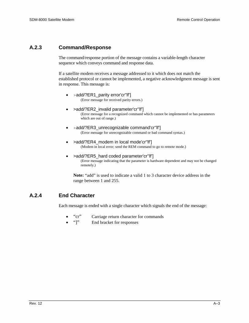
SDM-8000 Satellite Modem Remote Control Operation
Rev. 12 A–3
A.2.3 Command/Response
The command/response portion of the message contains a variable-length charactersequence which conveys command and response data.
If a satellite modem receives a message addressed to it which does not match theestablished protocol or cannot be implemented, a negative acknowledgment message is sentin response. This message is:
• >add/?ER1_parity error'cr''lf'](Error message for received parity errors.)
• >add/?ER2_invalid parameter'cr''lf'](Error message for a recognized command which cannot be implemented or has parameterswhich are out of range.)
• >add/?ER3_unrecognizable command'cr''lf'](Error message for unrecognizable command or bad command syntax.)
• >add/?ER4_modem in local mode'cr''lf'](Modem in local error; send the REM command to go to remote mode.)
• >add/?ER5_hard coded parameter'cr''lf'](Error message indicating that the parameter is hardware dependent and may not be changedremotely.)
Note: “add” is used to indicate a valid 1 to 3 character device address in therange between 1 and 255.
A.2.4 End Character
Each message is ended with a single character which signals the end of the message:
• “cr” Carriage return character for commands• “]” End bracket for responses

Remote Control Operation SDM-8000 Satellite Modem
A–4 Rev. 12
A.3 Configuration Commands/Responses
A.3.1 ModulatorModulatorFrequency
Command:Response:
Status:Response:
<add/MF_nnn.nnnn'cr'>add/MF_nnn.nnnn'cr'RF_OFF'cr''lf']
<add/MF_'cr'>add/MF_nnn.nnnn'cr''lf']
Where: nnn.nnnn = Frequency in MHz, 50.0000 to90.0000, and 100.0000 to 180.0000, in 2.5 kHz steps.
Note: When the modulator frequency is programmed, theRF output is switched off.
RF Output(IF Output)
Command:Response:
Status:Response:
<add/RF_xxx'cr'>add/RF_xxx'cr''lf']
<add/RF_'cr'>add/RF_xxx'cr''lf']
Where: xxx = ON or OFF.
ModulatorRate PresetAssignment
Command:Response:
Status:Response:
<add/AMRx_nnnnn_mmmm.mmm'cr'>add/AMRx_nnnnn_mmmm.mmm'cr''lf']
<add/AMRx_'cr'>add/AMRx_nnnnn_mmmm.mmm'cr''lf']
Where:
x = A, B, C, D, or V (Preset designator).
nnnnn = one of the following Coder rates: 1/2 (QPSK1/2), 3/4 (QPSK 3/4), 7/8 (QPSK 7/8), BP12 (BPSK1/2), 8P23 (8PSK 2/3), 8P56 (8PSK 5/6), 16Q34(16QAM 3/4), 16Q78 (16QAM 7/8), QPSK (QPSK 1/1).
mmmm.mmm = Data rate in kHz.
ModulatorRate PresetSelection
Command:Response:
Status:
<add/SMRx_'cr'>add/SMRx_'cr'RF_OFF'cr''lf']
See MR command.
Where: x = A, B, C, D, or V (Preset designator).
Note: Setting the modulator rate turns off the RFtransmitter.
ModulatorRateVariableAssignment& Selection
Command:Response:
Status:
<add/SMRV_nnnnn_mmmm.mmm'cr'>add/SMRV_nnnnn_mmmm.mmm'cr'RF_OFF'cr''lf']
See MR command.
Where:
nnnnn = one of the following Coder rates: 1/2 (QPSK1/2), 3/4 (QPSK 3/4), 7/8 (QPSK 7/8), BP12 (BPSK1/2), 8P23 (8PSK 2/3), 8P56 (8PSK 5/6), 16Q34(16QAM 3/4), 16Q78 (16QAM 7/8), QPSK (QPSK 1/1).
mmmm.mmm = Data rate in kHz.
Note: Setting the modulator turns off the RF transmitter.
SetModulatorPowerOffset
Command:Response:
Status:Response:
<add/MPO_snn.n'cr'>add/MPO_snn.n'cr''lf']
<add/MPO_'cr'>add/MPO_snn.n'cr''lf']
Where: snn.n = +99.9 to -69.9, in 0.1 dB increments.
Note: The modulator power offset is added to the nominalpower level to adjust the transmit power range.

SDM-8000 Satellite Modem Remote Control Operation
Rev. 12 A–5
SetModulatorOutputPower Level
Command:Response:
Status:Response:
<add/MOP_snn.n'cr'>add/MOP_snn.n'cr''lf']
<add/MOP_'cr'>add/MOP_snn.n'cr''lf']
Where: snn.n = -30.0 to -5.0, in 0.1 steps (nominal rangein dBm).
Notes:1. The nominal power range is modified relative to the
value specified by the modulator power offset(MPO_).
2. When TX Overhead is programmed for ASYNC,AUPC is installed, and AUPC local power enable'LPC_' is programmed 'ON'; the MOP (ModulatorOutput Power) command is not allowed. Only MOPstatus is allowed. See 'LPC_' command.
ScramblerEnable
Command:Response:
Status:Response:
<add/SE_xxx'cr'>add/SE_xxx'cr''lf']
<add/SE_'cr'>add/SE_xxx'cr''lf']
Where: xxx = ON or OFF.
DifferentialEncoderEnable
Command:Response:
Status:Response:
<add/DENC_xxx'cr'>add/DENC_xxx'cr''lf']
<add/DENC_'cr'>add/DENC_xxx'cr''lf']
Where: xxx = ON or OFF.
ModulatorType
Command:Response:
Status:Response:
<add/MT_xxxx'cr'>add/MT_xxxx'cr''lf']
<add/MT_xxxx'cr'>add/MT_xxxx'cr''lf']
Where: xxxx = INTL (INTELSAT OPEN NETWORK), EFD(EFData CLOSED NETWORK), CSC (COMSTREAMCLOSED NETWORK), or FDC (FAIRCHILD CLOSEDNETWORK).
ModulatorEncoderType
Command:Response:
Status:Response:
<add/MET_xxx'cr'>add/MET_xxx'cr''lf']
<add/MET_xxx'cr'>add/MET_xxx'cr''lf']
Where: xxx = VIT (K-7 VITERBI ENCODER) or SEQ(SEQUENTIAL ENCODER).
ModulatorReferenceClock
Command:Response:
Status:Response:
<add/MRC_xxxxx'cr'>add/MRC_xxxxx'cr''lf']
<add/MRC_'cr'>add/MRC_xxxxx'cr''lf']
Where: xxxxx = INT, EXT5 (5 MHz), EXT10 (10 MHz), orEXT20 (20 MHz).
ModulatorSpectrumRotation
Command:Response:
Status:Response:
<add/MSR_xxxx'cr'>add/MSR_xxxx'cr''lf']
<add/MSR_'cr'>add/MSR_xxxx'cr''lf']
Where: xxxx = NRM (normal spectrum) or INV (invertedspectrum).
Reed-SolomonEncoderEnable
Command:Response:
Status:Response:
<add/RSEN_xxx'cr'>add/RSEN_xxx'cr'’lf']
<add/RSEN_'cr'>add/RSEN_xxx'cr'’lf']
Where: xxx = ON or OFF.
TX 8PSK2/3IESS-310Operation
Command:Response:
Status:Response:
<add/T310_xxx'cr'>add/T310_xxx'cr''lf']
<add/T310_'cr'>add/T310_xxx'cr''lf']
Where: xxx = ON or OFF.
ModulatorSCT PLLReference
Command:Response:
Status:Response:
<add/MSPR_xxx'cr'>add/MSPR_xxx'cr''lf']
<add/MSPR_'cr'>add/MSPR_xxx'cr''lf']
Where: xxx = MR (MODULATOR REF.) or ERF (EXT-REFFREQ).
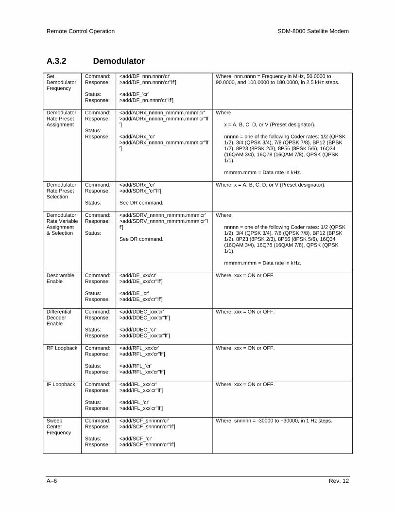
Remote Control Operation SDM-8000 Satellite Modem
A–6 Rev. 12
A.3.2 DemodulatorSetDemodulatorFrequency
Command:Response:
Status:Response:
<add/DF_nnn.nnnn'cr'>add/DF_nnn.nnnn'cr''lf']
<add/DF_'cr'>add/DF_nn.nnnn'cr''lf']
Where: nnn.nnnn = Frequency in MHz, 50.0000 to90.0000, and 100.0000 to 180.0000, in 2.5 kHz steps.
DemodulatorRate PresetAssignment
Command:Response:
Status:Response:
<add/ADRx_nnnnn_mmmm.mmm'cr'>add/ADRx_nnnnn_mmmm.mmm'cr''lf']
<add/ADRx_'cr'>add/ADRx_nnnnn_mmmm.mmm'cr''lf']
Where:
x = A, B, C, D, or V (Preset designator).
nnnnn = one of the following Coder rates: 1/2 (QPSK1/2), 3/4 (QPSK 3/4), 7/8 (QPSK 7/8), BP12 (BPSK1/2), 8P23 (8PSK 2/3), 8P56 (8PSK 5/6), 16Q34(16QAM 3/4), 16Q78 (16QAM 7/8), QPSK (QPSK1/1).
mmmm.mmm = Data rate in kHz.
DemodulatorRate PresetSelection
Command:Response:
Status:
<add/SDRx_'cr'>add/SDRx_'cr''lf']
See DR command.
Where: x = A, B, C, D, or V (Preset designator).
DemodulatorRate VariableAssignment& Selection
Command:Response:
Status:
<add/SDRV_nnnnn_mmmm.mmm'cr'>add/SDRV_nnnnn_mmmm.mmm'cr''lf']
See DR command.
Where:
nnnnn = one of the following Coder rates: 1/2 (QPSK1/2), 3/4 (QPSK 3/4), 7/8 (QPSK 7/8), BP12 (BPSK1/2), 8P23 (8PSK 2/3), 8P56 (8PSK 5/6), 16Q34(16QAM 3/4), 16Q78 (16QAM 7/8), QPSK (QPSK1/1).
mmmm.mmm = Data rate in kHz.
DescrambleEnable
Command:Response:
Status:Response:
<add/DE_xxx'cr'>add/DE_xxx'cr''lf']
<add/DE_'cr'>add/DE_xxx'cr''lf']
Where: xxx = ON or OFF.
DifferentialDecoderEnable
Command:Response:
Status:Response:
<add/DDEC_xxx'cr'>add/DDEC_xxx'cr''lf']
<add/DDEC_'cr'>add/DDEC_xxx'cr''lf']
Where: xxx = ON or OFF.
RF Loopback Command:Response:
Status:Response:
<add/RFL_xxx'cr'>add/RFL_xxx'cr''lf']
<add/RFL_'cr'>add/RFL_xxx'cr''lf']
Where: xxx = ON or OFF.
IF Loopback Command:Response:
Status:Response:
<add/IFL_xxx'cr'>add/IFL_xxx'cr''lf']
<add/IFL_'cr'>add/IFL_xxx'cr''lf']
Where: xxx = ON or OFF.
SweepCenterFrequency
Command:Response:
Status:Response:
<add/SCF_snnnnn'cr'>add/SCF_snnnnn'cr''lf']
<add/SCF_'cr'>add/SCF_snnnnn'cr''lf']
Where: snnnnn = -30000 to +30000, in 1 Hz steps.
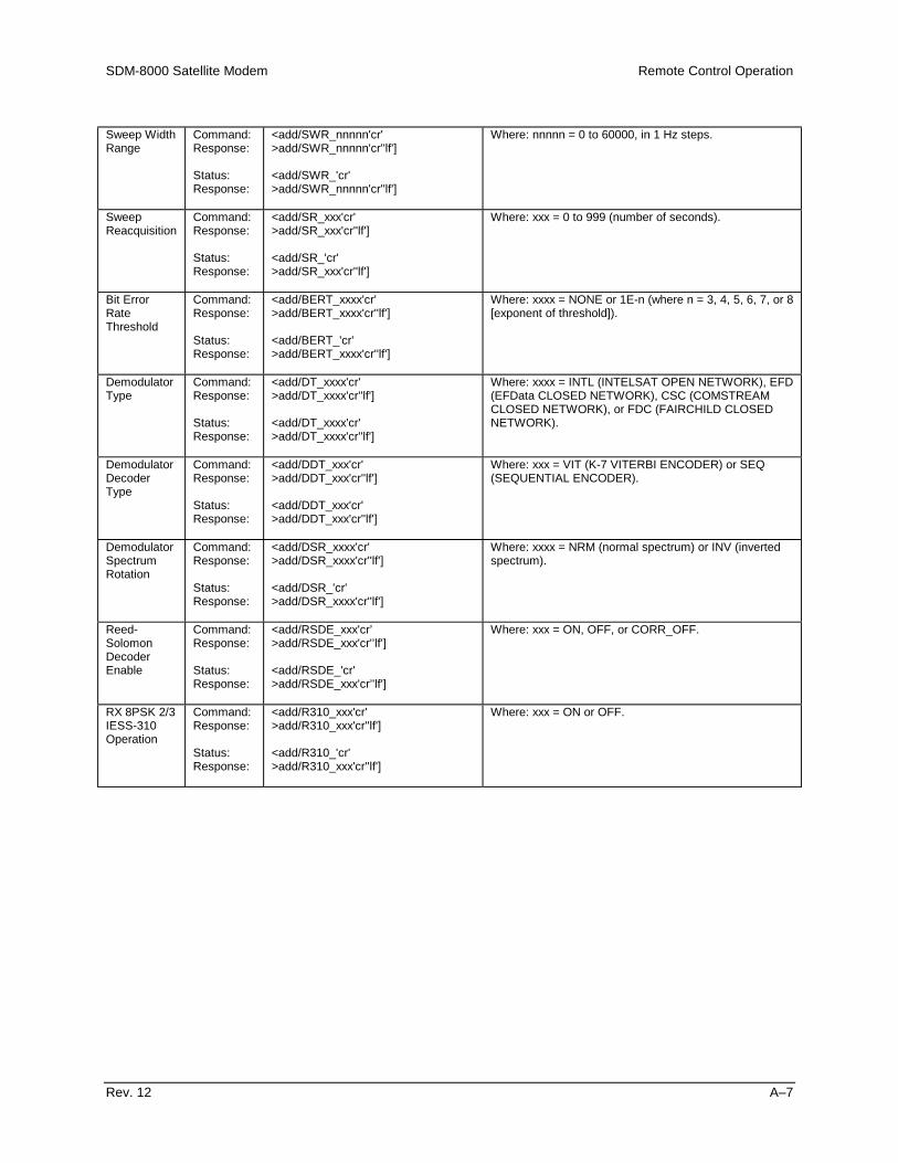
SDM-8000 Satellite Modem Remote Control Operation
Rev. 12 A–7
Sweep WidthRange
Command:Response:
Status:Response:
<add/SWR_nnnnn'cr'>add/SWR_nnnnn'cr''lf']
<add/SWR_'cr'>add/SWR_nnnnn'cr''lf']
Where: nnnnn = 0 to 60000, in 1 Hz steps.
SweepReacquisition
Command:Response:
Status:Response:
<add/SR_xxx'cr'>add/SR_xxx'cr''lf']
<add/SR_'cr'>add/SR_xxx'cr''lf']
Where: xxx = 0 to 999 (number of seconds).
Bit ErrorRateThreshold
Command:Response:
Status:Response:
<add/BERT_xxxx'cr'>add/BERT_xxxx'cr''lf']
<add/BERT_'cr'>add/BERT_xxxx'cr''lf']
Where: xxxx = NONE or 1E-n (where n = 3, 4, 5, 6, 7, or 8[exponent of threshold]).
DemodulatorType
Command:Response:
Status:Response:
<add/DT_xxxx'cr'>add/DT_xxxx'cr''lf']
<add/DT_xxxx'cr'>add/DT_xxxx'cr''lf']
Where: xxxx = INTL (INTELSAT OPEN NETWORK), EFD(EFData CLOSED NETWORK), CSC (COMSTREAMCLOSED NETWORK), or FDC (FAIRCHILD CLOSEDNETWORK).
DemodulatorDecoderType
Command:Response:
Status:Response:
<add/DDT_xxx'cr'>add/DDT_xxx'cr''lf']
<add/DDT_xxx'cr'>add/DDT_xxx'cr''lf']
Where: xxx = VIT (K-7 VITERBI ENCODER) or SEQ(SEQUENTIAL ENCODER).
DemodulatorSpectrumRotation
Command:Response:
Status:Response:
<add/DSR_xxxx'cr'>add/DSR_xxxx'cr''lf']
<add/DSR_'cr'>add/DSR_xxxx'cr''lf']
Where: xxxx = NRM (normal spectrum) or INV (invertedspectrum).
Reed-SolomonDecoderEnable
Command:Response:
Status:Response:
<add/RSDE_xxx'cr’>add/RSDE_xxx'cr'’lf']
<add/RSDE_'cr'>add/RSDE_xxx'cr’'lf']
Where: xxx = ON, OFF, or CORR_OFF.
RX 8PSK 2/3IESS-310Operation
Command:Response:
Status:Response:
<add/R310_xxx'cr'>add/R310_xxx'cr''lf']
<add/R310_'cr'>add/R310_xxx'cr''lf']
Where: xxx = ON or OFF.

Remote Control Operation SDM-8000 Satellite Modem
A–8 Rev. 12
A.3.3 Interface Configuration CommandsTransmitClock
Command:Response:
Status:Response:
<add/TC_xxx'cr'>add/TC_xxx'cr''lf']
<add/TC_'cr'>add/TC_xxx'cr''lf']
Where: xxx = INT (internal SCT clock), EXT (external TXterrestrial clock), or REF (external reference clock).
ExternalReferenceFrequency
Command:Response:
Status:Response:
<add/ERF_nnnnn.n'cr'>add/ERF_nnnnn.n'cr''lf']
<add/ERF_'cr'>add/ERF_nnnnn.n'cr''lf']
Where: nnnnn.n = 8.0 to 10000.0 (external referencefrequency in kHz).
TransmitClockPhase
Command:Response:
Status:Response:
<add/TCP_xxxx'cr'>add/TCP_xxxx'cr''lf']
<add/TCP_'cr'>add/TCP_xxxx'cr''lf']
Where: xxxx = NRM (normal clock phasing), INV (invertedclock phasing), or AUTO (automatic clock phasing).
ReceiveClockPhase
Command:Response:
Status:Response:
<add/RCP_xxxx'cr'>add/RCP_xxxx'cr''lf']
<add/RCP_'cr'>add/RCP_xxxx'cr''lf']
Where: xxxx = NRM (normal clock phasing) or INV (invertedclock phasing).
BasebandLoopback
Command:Response:
Status:Response:
<add/BBL_xxx'cr'>add/BBL_xxx'cr''lf']
<add/BBL_'cr'>add/BBL_xxx'cr''lf']
Where: xxx = ON or OFF.
InterfaceLoopback
Command:Response:
Status:Response:
<add/ILB_xxx'cr'>add/ILB_xxx'cr''lf']
<add/ILB_'cr'>add/ILB_xxx'cr''lf']
Where: xxx = ON or OFF.
InterfaceLoopTiming
Command:Response:
Status:Response:
<add/ILT_xxx'cr'>add/ILT_xxx'cr''lf']
<add/ILT_'cr'>add/ILT_xxx'cr''lf']
Where: xxx = ON or OFF.
InterfaceCodingFormatTransmit
Command:Response:
Status:Response:
<add/ICFT_xxxx'cr'>add/ICFT_xxxx'cr''lf']
<add/ICFT_'cr'>add/ICFT_xxxx'cr''lf']
Where: xxxx = AMI, HDB3, B6ZS, or B8ZS.
InterfaceCodingFormatReceive
Command:Response:
Status:Response:
<add/ICFR_xxxx'cr'>add/ICFR_xxxx'cr''lf']
<add/ICFR_'cr'>add/ICFR_xxxx'cr''lf']
Where: xxxx = AMI, HDB3, B6ZS, or B8ZS.
TransmitData Fault
Command:Response:
Status:Response:
<add/TDF_xxxx'cr'>add/TDF_xxxx'cr''lf']
<add/TDF_'cr'>add/TDF_xxxx'cr''lf']
Where: xxxx = NONE, DATA, or AIS.

SDM-8000 Satellite Modem Remote Control Operation
Rev. 12 A–9
ReceiveData Fault
Command:Response:
Status:Response:
<add/RDF_xxxx'cr'>add/RDF_xxxx'cr''lf']
<add/RDF_'cr'>add/RDF_xxxx'cr''lf']
Where: xxxx = NONE, DATA, or AIS.
Buffer Clock Command:Response:
Status:Response:
<add/BC_xxx'cr'>add/BC_xxx'cr''lf']
<add/BC_'cr'>add/BC_xxx'cr''lf']
Where: xxx = INT (internal SCT clock), EXT (external TXterrestrial clock), SAT (receive satellite clock), REF (externalreference clock), HS (internal high stability clock), or INS(insert clock).
InterfaceBuffer Size
Buffer size programming is supported in two formats, bits or milli-seconds. The selected format must be chosenusing the buffer programming command (IBP_). If the buffer is to be programmed in milli-seconds andplesiochronous slips are required, use the receive framing structure command (IRFS_) to define the proper framingformat.
Note: For Drop & Insert, only milli-seconds format is allowed.
InterfaceBuffer SizeBit Format
Command:Response:
Status:Response:
<add/IBS_nnnnnn'cr'>add/IBS_nnnnnn'cr''lf']
<add/IBS_'cr'>add/IBS_nnnnnn'cr''lf']
Where: nnnnnn = 32 to 262144, in 16-bit increments.
Note: For Drop & Insert, buffer size programming is always inmilli-seconds format.
InterfaceBuffer SizeMilli-secondFormat
Command:Response:
Status:Response:
<add/IBS_nn'cr'>add/IBS_nn'cr''lf']
<add/IBS_'cr'>add/IBS_nn'cr''lf']
Where: nn = 0 to 99 (buffer size in milli-seconds).
Note: For Drop & Insert,nn= 1, 2, 4, 8, 16, or 32 (buffer size in milli-seconds).nn= 7.5, 15, or 30 (buffer size in milli-seconds) for
E1CAS_format.nn= 6, 12, 24, or 30 (buffer size in milli-seconds) for
T1IBS_format.
InterfaceBufferCenter
Command:Response:
<add/IBC_'cr'>add/IBC_'cr''lf']
InterfaceSubstitutePattern
Command:Response:
Status:Response:
<add/ISP_xxx'cr'>add/ISP_xxx'cr''lf']
<add/ISP_'cr'>add/ISP_xxx'cr''lf']
Where: xxx = ON or OFF.
Note: Transmit 2047 Pattern.
InterfaceRead ErrorSelect
Command:Response:
Status:Response:
<add/IRE_xxxx'cr'>add/IRE_xxxx'cr''lf']
<add/IRE_'cr'>add/IRE_xxxx'cr''lf']
Where: xxxx = ON or OFF.
Note: Receive 2047 Pattern.
InterfaceServiceChannelLevel
Command:Response:
Status:Response:
<add/ISCL_xxx_snn'cr'>add/ISCL_xxx_snn'cr''lf']
<add/ISCL_xxx'cr'>add/ISCL_xxx_snn'cr''lf']
Where:xxx = TX1, TX2, RX1, or RX2 (service channel designator).nnn = -20 to +10, in steps of 1 (service channel level indBm).
InterfaceTransmitOverheadType
Command:Response:
Status:Response:
<add/ITOT_xxxxx'cr'>add/ITOT_xxxxx'cr''lf']
<add/ITOT_'cr'>add/ITOT_xxxxx'cr''lf']
Where: xxxx = NONE, IDR, IBS, DI, DVB, or ASYNC.
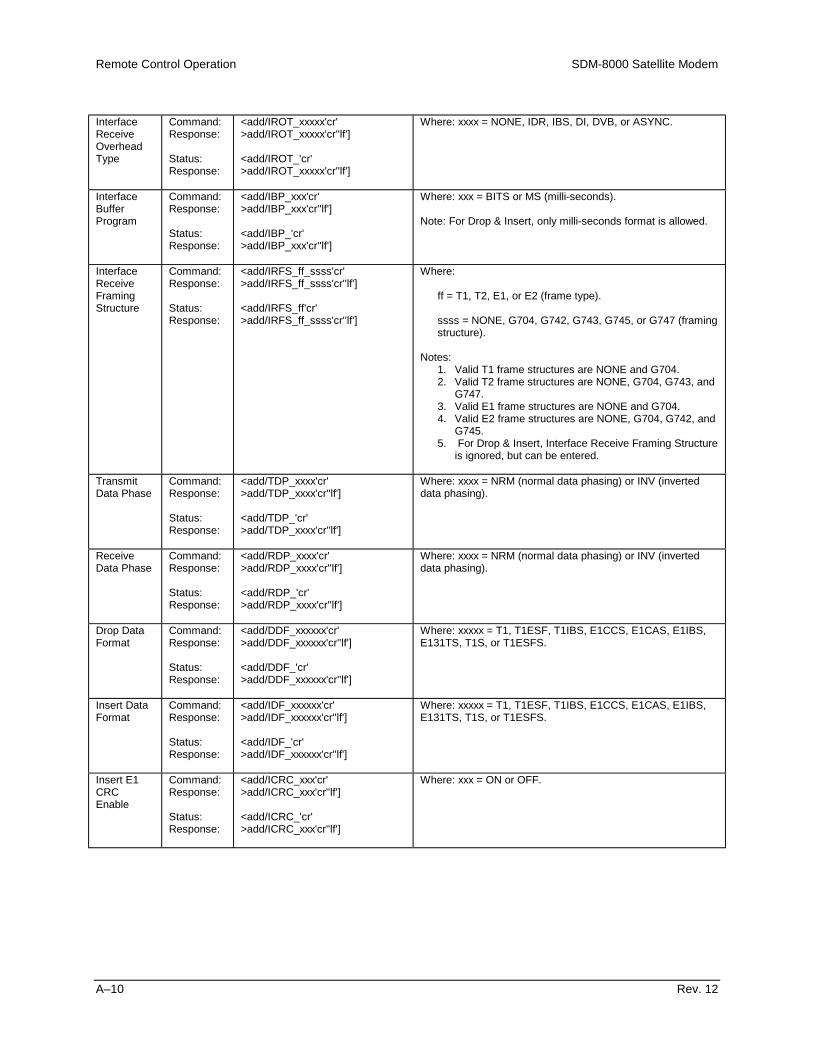
Remote Control Operation SDM-8000 Satellite Modem
A–10 Rev. 12
InterfaceReceiveOverheadType
Command:Response:
Status:Response:
<add/IROT_xxxxx'cr'>add/IROT_xxxxx'cr''lf']
<add/IROT_'cr'>add/IROT_xxxxx'cr''lf']
Where: xxxx = NONE, IDR, IBS, DI, DVB, or ASYNC.
InterfaceBufferProgram
Command:Response:
Status:Response:
<add/IBP_xxx'cr'>add/IBP_xxx'cr''lf']
<add/IBP_'cr'>add/IBP_xxx'cr''lf']
Where: xxx = BITS or MS (milli-seconds).
Note: For Drop & Insert, only milli-seconds format is allowed.
InterfaceReceiveFramingStructure
Command:Response:
Status:Response:
<add/IRFS_ff_ssss'cr'>add/IRFS_ff_ssss'cr''lf']
<add/IRFS_ff'cr'>add/IRFS_ff_ssss'cr''lf']
Where:
ff = T1, T2, E1, or E2 (frame type).
ssss = NONE, G704, G742, G743, G745, or G747 (framingstructure).
Notes:1. Valid T1 frame structures are NONE and G704.2. Valid T2 frame structures are NONE, G704, G743, and
G747.3. Valid E1 frame structures are NONE and G704.4. Valid E2 frame structures are NONE, G704, G742, and
G745.5. For Drop & Insert, Interface Receive Framing Structure
is ignored, but can be entered.
TransmitData Phase
Command:Response:
Status:Response:
<add/TDP_xxxx'cr'>add/TDP_xxxx'cr''lf']
<add/TDP_'cr'>add/TDP_xxxx'cr''lf']
Where: xxxx = NRM (normal data phasing) or INV (inverteddata phasing).
ReceiveData Phase
Command:Response:
Status:Response:
<add/RDP_xxxx'cr'>add/RDP_xxxx'cr''lf']
<add/RDP_'cr'>add/RDP_xxxx'cr''lf']
Where: xxxx = NRM (normal data phasing) or INV (inverteddata phasing).
Drop DataFormat
Command:Response:
Status:Response:
<add/DDF_xxxxxx'cr'>add/DDF_xxxxxx'cr''lf']
<add/DDF_'cr'>add/DDF_xxxxxx'cr''lf']
Where: xxxxx = T1, T1ESF, T1IBS, E1CCS, E1CAS, E1IBS,E131TS, T1S, or T1ESFS.
Insert DataFormat
Command:Response:
Status:Response:
<add/IDF_xxxxxx'cr'>add/IDF_xxxxxx'cr''lf']
<add/IDF_'cr'>add/IDF_xxxxxx'cr''lf']
Where: xxxxx = T1, T1ESF, T1IBS, E1CCS, E1CAS, E1IBS,E131TS, T1S, or T1ESFS.
Insert E1CRCEnable
Command:Response:
Status:Response:
<add/ICRC_xxx'cr'>add/ICRC_xxx'cr''lf']
<add/ICRC_'cr'>add/ICRC_xxx'cr''lf']
Where: xxx = ON or OFF.
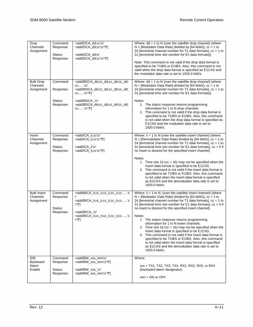
SDM-8000 Satellite Modem Remote Control Operation
Rev. 12 A–11
DropChannelsAssignment
Command:Response:
Status:Response:
<add/DCA_dd;cc'cr'>add/DCA_dd;cc'cr''lf']
<add/DCA_dd'cr'>add/DCA_dd;cc'cr''lf']
Where: dd = 1 to N (over the satellite drop channel) (whereN = [Modulator Data Rate] divided by [64 kbit/s], cc = 1 to24 [terrestrial channel number for T1 data formats], cc = 1 to31 [terrestrial time slot number for E1 data formats]).
Note: This command is not valid if the drop data format isspecified to be T1IBS or E1IBS. Also, this command is notvalid when the drop data format is specified as E1CAS andthe modulator data rate is set to 1920.0 kbit/s.
Bulk DropChannelsAssignment
Command:
Response:
Status:Response:
<add/BDCA_dd;cc_dd;cc_dd;cc_dd;cc......'cr'>add/BDCA_dd;cc_dd;cc_dd;cc_dd;cc......'cr''lf']
<add/BDCA_'cr'>add/BDCA_dd;cc_dd;cc_dd;cc_dd;cc......'cr''lf']
Where: dd = 1 to N (over the satellite drop channel) (whereN = [Modulator Data Rate] divided by [64 kbit/s], cc = 1 to24 [terrestrial channel number for T1 data formats], cc = 1 to31 [terrestrial time slot number for E1 data formats]).
Notes:1. The status response returns programming
information for 1 to N drop channels.2. This command is not valid if the drop data format is
specified to be T1IBS or E1IBS. Also, this commandis not valid when the drop data format is specified asE1CAS and the modulator data rate is set to1920.0 kbit/s.
InsertChannelsAssignment
Command:Response:
Status:Response:
<add/ICA_ii;cc'cr'>add/ICA_ii;cc'cr''lf']
<add/ICA_ii'cr'>add/ICA_ii;cc'cr''lf']
Where: ii = 1 to N (over the satellite insert channel) (whereN = [Demodulator Data Rate] divided by [64 kbit/s], cc = 1 to24 [terrestrial channel number for T1 data formats], cc = 1 to31 [terrestrial time slot number for E1 data formats], cc = 0 ifno insert is desired for the specified insert channel).
Notes:1. Time slot 16 (cc = 16) may not be specified when the
insert data format is specified to be E1CAS.2. This command is not valid if the insert data format is
specified to be T1IBS or E1IBS. Also, this commandis not valid when the insert data format is specifiedas E1CAS and the demodulator data rate is set to1920.0 kbit/s.
Bulk InsertChannelsAssignment
Command:Response:
Status:Response:
<add/BICA_ii;cc_ii;cc_ii;cc_ii;cc......'cr'>add/BICA_ii;cc_ii;cc_ii;cc_ii;cc......'cr''lf']
<add/BICA_'cr'>add/BICA_ii;cc_ii;cc_ii;cc_ii;cc......'cr''lf']
Where: ii = 1 to N, (over the satellite insert channel) (whereN = [Modulator Data Rate] divided by [64 kbit/s], cc = 1 to24 [terrestrial channel number for T1 data formats], cc = 1 to31 [terrestrial time slot number for E1 data formats], cc = 0 ifno insert is desired for the specified insert channel).
Notes:1. The status response returns programming
information for 1 to N insert channels.2. Time slot 16 (cc = 16) may not be specified when the
insert data format is specified to be E1CAS.3. This command is not valid if the insert data format is
specified to be T1IBS or E1IBS. Also, this commandis not valid when the insert data format is specifiedas E1CAS and the demodulator data rate is set to1920.0 kbit/s.
IDRBackwardAlarmEnable
Command:Response:
Status:Response:
<add/BW_xxx_nnn'cr'>add/BW_xxx_nnn'cr''lf']
<add/BW_xxx_'cr'>add/BW_xxx_nnn'cr''lf']
Where:
xxx = TX1, TX2, TX3, TX4, RX1, RX2, RX3, or RX4(backward alarm designator).
nnn = ON or OFF.
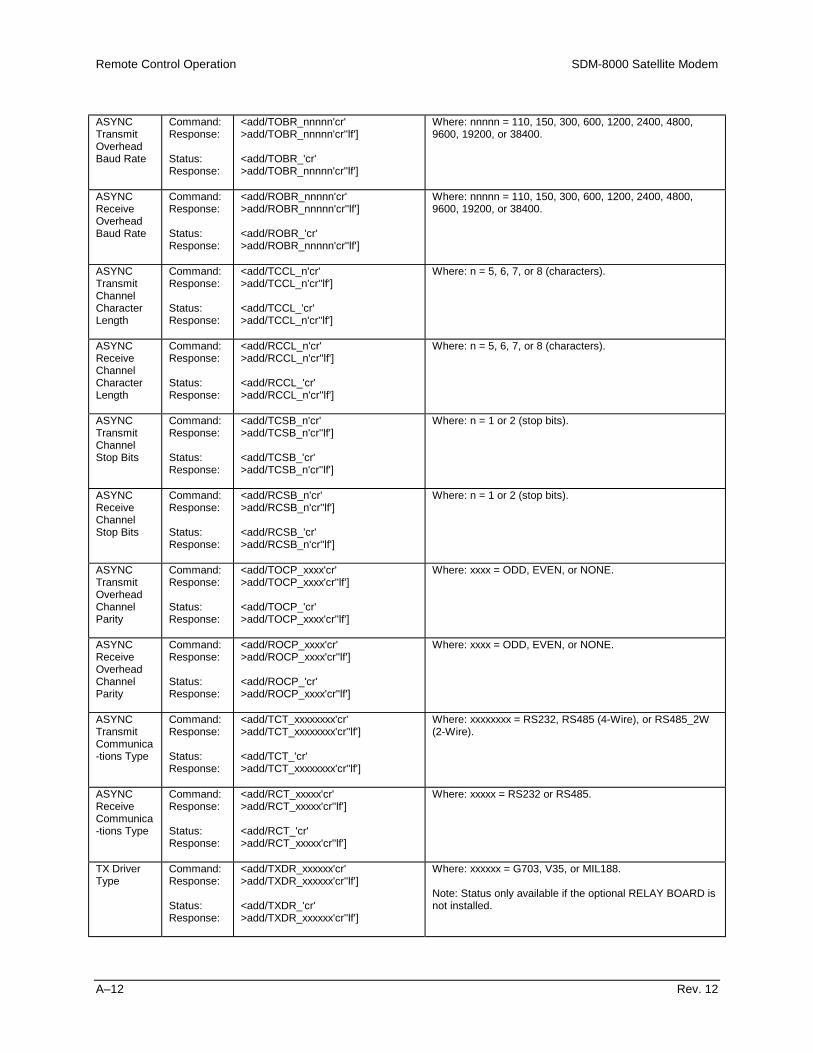
Remote Control Operation SDM-8000 Satellite Modem
A–12 Rev. 12
ASYNCTransmitOverheadBaud Rate
Command:Response:
Status:Response:
<add/TOBR_nnnnn'cr'>add/TOBR_nnnnn'cr''lf']
<add/TOBR_'cr'>add/TOBR_nnnnn'cr''lf']
Where: nnnnn = 110, 150, 300, 600, 1200, 2400, 4800,9600, 19200, or 38400.
ASYNCReceiveOverheadBaud Rate
Command:Response:
Status:Response:
<add/ROBR_nnnnn'cr'>add/ROBR_nnnnn'cr''lf']
<add/ROBR_'cr'>add/ROBR_nnnnn'cr''lf']
Where: nnnnn = 110, 150, 300, 600, 1200, 2400, 4800,9600, 19200, or 38400.
ASYNCTransmitChannelCharacterLength
Command:Response:
Status:Response:
<add/TCCL_n'cr'>add/TCCL_n'cr''lf']
<add/TCCL_'cr'>add/TCCL_n'cr''lf']
Where: n = 5, 6, 7, or 8 (characters).
ASYNCReceiveChannelCharacterLength
Command:Response:
Status:Response:
<add/RCCL_n'cr'>add/RCCL_n'cr''lf']
<add/RCCL_'cr'>add/RCCL_n'cr''lf']
Where: n = 5, 6, 7, or 8 (characters).
ASYNCTransmitChannelStop Bits
Command:Response:
Status:Response:
<add/TCSB_n'cr'>add/TCSB_n'cr''lf']
<add/TCSB_'cr'>add/TCSB_n'cr''lf']
Where: n = 1 or 2 (stop bits).
ASYNCReceiveChannelStop Bits
Command:Response:
Status:Response:
<add/RCSB_n'cr'>add/RCSB_n'cr''lf']
<add/RCSB_'cr'>add/RCSB_n'cr''lf']
Where: n = 1 or 2 (stop bits).
ASYNCTransmitOverheadChannelParity
Command:Response:
Status:Response:
<add/TOCP_xxxx'cr'>add/TOCP_xxxx'cr''lf']
<add/TOCP_'cr'>add/TOCP_xxxx'cr''lf']
Where: xxxx = ODD, EVEN, or NONE.
ASYNCReceiveOverheadChannelParity
Command:Response:
Status:Response:
<add/ROCP_xxxx'cr'>add/ROCP_xxxx'cr''lf']
<add/ROCP_'cr'>add/ROCP_xxxx'cr''lf']
Where: xxxx = ODD, EVEN, or NONE.
ASYNCTransmitCommunica-tions Type
Command:Response:
Status:Response:
<add/TCT_xxxxxxxx'cr'>add/TCT_xxxxxxxx'cr''lf']
<add/TCT_'cr'>add/TCT_xxxxxxxx'cr''lf']
Where: xxxxxxxx = RS232, RS485 (4-Wire), or RS485_2W(2-Wire).
ASYNCReceiveCommunica-tions Type
Command:Response:
Status:Response:
<add/RCT_xxxxx'cr'>add/RCT_xxxxx'cr''lf']
<add/RCT_'cr'>add/RCT_xxxxx'cr''lf']
Where: xxxxx = RS232 or RS485.
TX DriverType
Command:Response:
Status:Response:
<add/TXDR_xxxxxx'cr'>add/TXDR_xxxxxx'cr''lf']
<add/TXDR_'cr'>add/TXDR_xxxxxx'cr''lf']
Where: xxxxxx = G703, V35, or MIL188.
Note: Status only available if the optional RELAY BOARD isnot installed.

SDM-8000 Satellite Modem Remote Control Operation
Rev. 12 A–13
RX DriverType
Command:Response:
Status:Response:
<add/RXDR_xxxxxx'cr'>add/RXDR_xxxxxx'cr''lf']
<add/RXDR_'cr'>add/RXDR_xxxxxx'cr''lf']
Where: xxxxxx = G703, V35, or MIL188.
Note: Status only available if the optional RELAY BOARD isnot installed.
G703 LevelSelect
Command:Response:
Status:Response:
<add/G703_xx'cr'>add/G703_xx'cr''lf']
<add/G703_'cr'>add/G703_xx'cr''lf']
Where: xx = HD (high drive), NL (nominal level), NS(nominal shaped), LL (low level), or LS (low shaped).
Note: Optional RELAY BOARD must be installed.
TransmitDVBFraming
Command:Response:
Status:Response:
<add/TDVB_xxxx'cr'>add/TDVB_xxxx'cr''lf']
<add/TDVB_'cr'>add/TDVB_xxxx'cr''lf']
Where: xxxx = 188, 204, or NONE.
Note: DVB Reed-Solomon board must be installed.
ReceiveDVBFraming
Command:Response:
Status:Response:
<add/RDVB_xxxx'cr'>add/RDVB_xxxx'cr''lf']
<add/RDVB_'cr'>add/RDVB_xxxx'cr''lf']
Where: xxxx = 188, 204, or NONE.
Note: DVB Reed-Solomon board must be installed.
IDR ESCType
Command:Response:
Status:Response:
<add/ESCT_xxxxx’cr’>add/ESCT_xxxxx’cr’’lf’]
<add/ESCT_’cr’>add/ESCT_xxxxx’cr’’lf’]
Where: xxxxx = Data (64K Data) or Auto (2x32K Audio)
Note: Status only available if the optional RELAY BOARD isnot installed.

Remote Control Operation SDM-8000 Satellite Modem
A–14 Rev. 12
A.3.4 SystemTime of Day Command:
Response:
Status:Response:
<add/TIME_hh:mmxx'cr'>add/TIME_hh:mmxx'cr''lf']
<add/TIME_'cr'>add/TIME_hh:mmxx'cr''lf']
Where:hh = 1 to 12 (hours).mm = 00 to 59 (minutes).xx = AM or PM.
Date Command:Response:
Status:Response:
<add/DATE_mm/dd/yy'cr'>add/DATE_mm/dd/yy'cr''lf']
<add/DATE_'cr'>add/DATE_mm/dd/yy'cr''lf']
Where:mm = 1 to 12 (month).dd = 1 to 31 (day).yy = 00 to 99 (year).
Remote Command:Response:
<add/REM_'cr'>add/REM_'cr''lf']
This command configures the modem for remote operation.The modem will respond to any status request at any time.However, the modem must be in 'Remote Mode' to changeconfiguration parameters.
ClearStoredFaults
Command:Response:
<add/CLSF_'cr'>add/CLSF_'cr''lf']
This command is used to clear all stored faults logged by themodem.
ModemOperationMode
Command:Response:
Status:Response:
<add/MOM_xxxxxxx'cr'>add/MOM_xxxxxxx'cr''lf']
<add/MOM_'cr'>add/MOM_xxxxxxx'cr''lf']
Where: xxxxxxx = TX_ONLY, RX_ONLY, or DUPLEX.
This command configures the modem for simplex or duplexoperation modes. When transmit only mode is selected,receive faults are inhibited. When receive only mode isselected, transmit faults are inhibited.
SystemModemType
Command:Response:
Status:Response:
<add/SMT_xxxxxx'cr'>add/SMT_xxxxxx'cr''lf']
<add/SMT_'cr'>add/SMT_xxxxxx'cr''lf']
Where: xxxxxx = IDR, IBS, DI, ASYNC, DVB, CUSTOM, orTYPE n (n = 1 to 5).
SaveModemConfig
Command:Response:
<add/SMC_n'cr'>add/SMC_n'cr''lf']
Where: n = 1, 2, 3, 4, or 5 (stored configuration number).
This command saves the current modem configuration forrecall at a later time using the 'RMC_' command. Up to fivedifferent modem configurations can be saved.
RecallModemConfig
Command:Response:
<add/RMC_n'cr'>add/RMC_n'cr''lf']
Where: n = 1, 2, 3, 4, or 5 (stored configuration number).
This command causes the modem to be reprogrammed withconfiguration parameters previously saved using the 'SMC_'command. One of five saved configurations can be specified.
RF ModeControl
Command:Response:
Status:Response:
<add/RFMD_xxxx’cr’>add/RFMD_xxxx’cr’’lf’]
<add/RFMD_’cr’>add/RFMD_xxxx’cr’’lf’]
Where xxxx = NRM (Normal Mode), PWR (Turn RF Off/On)COMM (Turn RF Off/On and Loss of Remote Communicationsafter 10 seconds if no command is received), CD (Turn RF Onwhen carrier is detected, turn RF Off when no carrier isdetected, For the RF On condition, the TX-IF mustprogrammed On.)
This command allows for the RF output to be enabled ordisabled. One application for this command is in demandnetwork systems.

SDM-8000 Satellite Modem Remote Control Operation
Rev. 12 A–15
A.3.5 AUPCAUPC LocalPowerEnable
Command:Response:
Status:Response:
<add/LPC_xxx'cr'>add/LPC_xxx'cr''lf']
<add/LPC_'cr'>add/LPC_xxx'cr''lf']
Where: xxx = ON or OFF.
Note: When programmed ON, the MOP (Modulator OutputPower) command is not allowed; only MOP status is allowed.
AUPCNominalPower Level
Command:Response:
Status:Response:
<add/NOMP_snn.n'cr'>add/NOMP_snn.n'cr''lf']
<add/NOMP_'cr'>add/NOMP_snn.n'cr''lf']
Where: snn.n = -30.0 to -5.0, in 0.1 steps (nominal range indBm).
Note: The nominal power range is modified relative to thevalue specified by the modulator power offset (MPO_).
AUPCMaximumPower Limit
Command:Response:
Status:Response:
<add/MAXP_snn.n'cr'>add/MAXP_snn.n'cr''lf']
<add/MAXP_'cr'>add/MAXP_snn.n'cr''lf']
Where: snn.n = -30.0 to -5.0, in 0.1 steps (nominal range indBm).
Note: The nominal power range is modified relative to thevalue specified by the modulator power offset (MPO_).
AUPCMinimumPower Limit
Command:Response:
Status:Response:
<add/MINP_snn.n'cr'>add/MINP_snn.n'cr''lf']
<add/MINP_'cr'>add/MINP_snn.n'cr''lf']
Where: snn.n = -30.0 to -5.0, in 0.1 steps (nominal range indBm).
Note: The nominal power range is modified relative to thevalue specified by the modulator power offset (MPO_).
AUPCEb/N0
Target SetPoint
Command:Response:
Status:Response:
<add/ENSP_nn.n'cr'>add/ENSP_nn.n'cr''lf']
<add/ENSP_'cr'>add/ENSP_nn.n'cr''lf']
Where: nn.n = 3.2 to 16.0, in 0.1 increments (Eb/N0 in dB).
AUPCMaximumTrackingRate
Command:Response:
Status:Response:
<add/MAXT_n.n'cr'>add/MAXT_n.n'cr''lf']
<add/MAXT_'cr'>add/MAXT_n.n'cr''lf']
Where: n.n = 0.5 to 6.0, in 0.5 increments (maximum trackingrate in dBm/minute).
AUPC LocalCarrier LossAction
Command:Response:
Status:Response:
<add/LCL_xxxx'cr'>add/LCL_xxxx'cr''lf']
<add/LCL_'cr'>add/LCL_xxxx'cr''lf']
Where: xxxx = HOLD, NOM, or MAX (power level setting whenlocal carrier loss).
AUPCRemoteCarrier LossAction
Command:Response:
Status:Response:
<add/RCL_xxxx'cr'>add/RCL_xxxx'cr''lf']
<add/RCL_'cr'>add/RCL_xxxx'cr''lf']
Where: xxxx = HOLD, NOM, or MAX (power level setting whenremote carrier loss).
RemoteModemAUPCCommands
Note: Always wait 3 seconds between consecutive remote modem command/status polls.
RemoteAUPCEnable
Command:Response:
Status:Response:
<add/RPC_xxx'cr'>add/RPC_xxx'cr''lf']
<add/RPC_'cr'>add/RPC_xxx'cr''lf']
Where: xxx = ON or OFF (remote AUPC enable).

Remote Control Operation SDM-8000 Satellite Modem
A–16 Rev. 12
RemoteInterfaceSubstitutionPattern
Command:Response:
Status:Response:
<add/RISP_xxx'cr'>add/RISP_xxx'cr''lf']
<add/RISP_'cr'>add/RISP_xxx'cr''lf']
Where: xxx = ON or OFF (remote transmit 2047 patternenable).
Note: Transmit 2047 Pattern.
RemoteInterfaceBasebandLoopback
Command:Response:
Status:Response:
<add/RBBL_xxx'cr'>add/RBBL_xxx'cr''lf']
<add/RBBL_'cr'>add/RBBL_xxx'cr''lf']
Where: xxx = ON or OFF (remote baseband loopback enable).
RemoteInterfaceRead ErrorStatus
Command:Response:
Example:
Command: Response:
<add/RRES_'cr'>add/RRES_nE-e'cr''lf']
<add/RRES_'cr'>add/RRES_2E-6'cr''lf']
Where:n = 1 to 9 (error rate number).e = 2 to 6 (exponent).
This command returns 2047 BER from the remote AUPCmodem. If data is not valid, the message 'No_Data' is returnedinstead of BER data.
Note: Received 2047 pattern.

SDM-8000 Satellite Modem Remote Control Operation
Rev. 12 A–17
A.4 Status Commands/Responses
A.4.1 ConfigurationModulatorConfigStatus
Command:Response:
<add/MCS_'cr'>add/MCS_'cr'RF_xxx'cr'MF_nnn.nnnn'cr'MR_nnnnn_mmmm.mmm'cr'AMRA_nnnnn_mmmm.mmm'cr'AMRB_nnnnn_mmmm.mmm'cr'AMRC_nnnnn_mmmm.mmm'cr'AMRD_nnnnn_mmmm.mmm'cr'AMRV_nnnnn.mmmm.mmm'cr'MPO_snn.n'cr'MOP_snn.n'cr'SE_xxx'cr'DENC_xxx'cr'MT_xxxx'cr'MET_xxx'cr'COM_xxx'cr'MRC_xxx'cr' (Note 1)MSR_xxx'cr'RSEN_xxx'cr' (Note 2)T310_xxx'cr' (Note 2)MSPR_xxx'cr''lf'] (Note 1)
RF Output (ON/OFF)Modulator FrequencyModulator RatePreset 'A' AssignmentPreset 'B' AssignmentPreset 'C' AssignmentPreset 'D' AssignmentPreset 'V' AssignmentModulator Power OffsetModulator Output PowerScrambler Enable (ON/OFF)Differential Encoder (ON/OFF)Modulator TypeModulator Encoder TypeCarrier Only Mode (ON/OFF)Modulator Reference ClockModulator Spectrum RotationReed-Solomon Encoder (ON/OFF)TX 8PSK 2/3 IESS-310 OperationModulator SCT PLL Reference
The modulator configuration status command causes a blockof data to be returned by the addressed modem. The block ofdata reflects the current configuration status of the modulatormodule. Additional configuration status of new options andfeatures will always be appended to the end.
Notes:1. Data will only be returned if the modulator board has
the High Stability Internal 5 MHz/External Divideroption.
2. Data is only returned if the Reed-Solomon option isinstalled on the interface board.

Remote Control Operation SDM-8000 Satellite Modem
A–18 Rev. 12
Modulator/CoderConfigProgramStatus
Command:Response:
<add/MCP_'cr'>add/MCP_'cr'SMT_xxxxxx'cr'ITOT_xxxx'cr'MOM_xxxxxxx'cr'MT_xxxx'cr'MET_xxx'cr'MF_nnn.nnnn'cr'MR_nnnnn_mmmm.mmm'cr'MPO_snn.n'cr'LPC_xxx'cr' (Note 1)MOP_snn.n'cr' (Note 2)SE_xxx'cr'DENC_xxx'cr'ERF_nnnnn.n'cr'TC_xxx'cr'TCP_xxxx'cr'BBL_xxx'cr'ILB_xxx'cr'ILT_xxx'cr'ICFT_xxxx'cr'ISP_xxx'cr'TDF_xxxx'cr'ISCL_TX1_nnn'cr'ISCL_TX2_nnn'cr'TDP_xxxx'cr'DDF_xxxxxx'cr' (Note 3)BDCA_dd;cc_dd;cc...'cr' (Note 3)MRC_xxx'cr'MSR_xxx'cr'RSEN_xxx'cr'BW_TX1_nnn'cr' (Note 4)BW_TX2_nnn'cr' (Note 4)BW_TX3_nnn'cr' (Note 4)BW_TX4_nnn'cr' (Note 4)TXDR_xxxxxx'cr'TOBR_nnnnn'cr' (Note 5)TCCL_n'cr' (Note 5)TCSB_n'cr' (Note 5)TOCP_xxxx'cr' (Note 5)TCT_xxxxxxxx'cr' (Note 5)NOMP_snn.n'cr' (Note 5)MINP_snn.n'cr' (Note 5)MAXP_snn.n'cr' (Note 5)LCL_xxxx'cr' (Note 5)RCL_xxxx'cr' (Note 5)TDVB_xxxx'cr' (Note 6)T310_xxx'cr'MSPR_xxx'cr'RF_xxx'cr''lf']
System Modem TypeInterface Transmit Overhead TypeModem Operation ModeModulator TypeModulator Encoder TypeModulator FrequencyModulator RateModulator Power OffsetAUPC Local Power EnableModulator Output PowerScrambler Enable (ON/OFF)Differential Encoder (ON/OFF)External Reference FrequencyTransmit Clock (Source)Transmit Clock PhaseBaseband LoopbackInterface LoopbackInterface Loop TimingInterface Coding Format TransmitInterface Substitution Pattern (TX 2047)Transmit Data FaultService Channel Level TX1Service Channel Level TX2Transmit Data PhaseDrop Data FormatBulk Drop Channels AssignmentModulator Reference ClockModulator Spectrum RotationReed-Solomon Encoder (ON/OFF)Backward Alarm Enable TX1Backward Alarm Enable TX2Backward Alarm Enable TX3Backward Alarm Enable TX4TX Driver TypeASYNC TX Overhead Baud RateASYNC TX Channel Character LengthASYNC TX Channel Stop BitsASYNC TX Overhead Channel ParityASYNC TX Communications TypeAUPC Nominal Power ValueAUPC Minimum Power ValueAUPC Maximum Power ValueAUPC Local Carrier LossAUPC Remote Carrier LossTransmit DVB FramingTX 8PSK 2/3 IESS-310 OperationModulator SCT PLL ReferenceRF Output (ON/OFF)
This command is used by the EFData M:N protection switch tocollect information that is necessary to configure back-upmodems. Because this command (content and/or order) canbe changed at any time by EFData, it is advisable that othercommands ('MCS_' and 'ICS_', or 'BCS_') be used for M&Csystems.
Notes:

SDM-8000 Satellite Modem Remote Control Operation
Rev. 12 A–19
1. Data is only returned for ASYNC TX Overhead andAUPC installed.
2. Data is only returned for ASYNC TX Overhead, AUPCinstalled, and Local AUPC is disabled (OFF).
3. Data is only returned for D&I TX Overhead.4. Data is only returned for IDR TX Overhead.5. Data is only returned for ASYNC TX Overhead.6. DVB Reed-Solomon board must be installed.
Demodulator ConfigStatus
Command:Response:
<add/DCS_'cr'>add/DCS_'cr'DF_nnn.nnnn'cr'DR_nnnnn_mmmm.mmm'cr'ADRA_nnnnn_mmmm.mmm'cr'ADRB_nnnnn_mmmm.mmm'cr'ADRC_nnnnn_mmmm.mmm'cr'ADRD_nnnnn_mmmm.mmm'cr'ADRV_nnnnn.mmmm.mmm'cr'DE_xxx'cr'DDEC_xxx'cr'RFL_xxx'cr'IFL_xxx'cr'SCF_snnnnn'cr'SWR_nnnnn'cr'SR_xxx'cr'BERT_xxxx'cr'DT_xxxx'cr'DDT_xxx'cr'DSR_xxx'cr'RSDE_xxx'cr' (See Note)R310_xxx'cr''lf'] (See Note)
Demodulator FrequencyDemodulator RatePreset 'A' AssignmentPreset 'B' AssignmentPreset 'C' AssignmentPreset 'D' AssignmentPreset 'V' AssignmentDescrambler EnableDifferential DecoderRF LoopbackIF LoopbackSweep Center FrequencySweep Width RangeSweep ReacquisitionBER ThresholdDemodulator TypeDemodulator Decoder TypeDemodulator Spectrum RotationReed-Solomon DecoderRX 8PSK 2/3 IESS-310 Operation
The Demodulator configuration status command causes ablock of data to be returned by the addressed modem. Theblock of data reflects the current configuration of the demod.Additional configuration status of new options and features willalways be appended to the end.
Note: Data is only returned if the Reed-Solomon option isinstalled on the interface board.

Remote Control Operation SDM-8000 Satellite Modem
A–20 Rev. 12
Demod/DecoderConfigProgramStatus
Command:Response:
<add/DCP_'cr'>add/DCP_'cr'SMT_xxxxxx'cr'IROT_xxxx'cr'MOM_xxxxxxx'cr'BERT_xxxx'cr'DT_xxxx'cr'DDT_xxx'cr'DF_nnn.nnnn'cr'DR_nnnnn_mmmm.mmm'cr'DE_xxx'cr'DDEC_xxx'cr'RFL_xxx'cr'IFL_xxx'cr'SCF_snnnnn'cr'SWR_nnnnn'cr'SR_xxx'cr'ERF_nnnnn.n'cr'BC_xxx'cr'RCP_xxxx'cr'BBL_xxx'cr'ILB_xxx'cr'ILT_xxx'cr'ICFR_xxxx'cr'IRFS_T1_ssss'cr'IRFS_T2_ssss'cr'IRFS_E1_ssss'cr'IRFS_E2_ssss'cr'IBP_xxx'cr'IRE_xxxx'cr'RDF_xxxx'cr'ISCL_RX1_nnn'cr'ISCL_RX2_nnn'cr'RDP_xxxx'cr'IDF_xxxxxx'cr' (Note 1)ICRC_xxx'cr' (Note 1)IBS_nnnnnn'cr'BICA_dd;cc_dd;cc...'cr' (Note 1)DSR_xxx'cr'RSDE_xxx'cr'BW_RX1_nnn'cr' (Note 2)BW_RX2_nnn'cr' (Note 2)BW_RX3_nnn'cr' (Note 2)BW_RX4_nnn'cr' (Note 2)RXDR_xxxxxx'cr'G703_xx'cr'ROBR_nnnnn'cr' (Note 3)RCCL_n'cr' (Note 3)RCSB_n'cr' (Note 3)ROCP_xxxx'cr' (Note 3)RCT_xxxxx'cr' (Note 3)ENSP_nn.n'cr' (Note 4)MAXT_n.n'cr' (Note 4)RDVB_xxxx'cr'ESCT_xxxxx'cr' (Note 3)R310_xxx'cr''lf']
System Modem TypeInterface Receive Overhead TypeModem Operation ModeBER ThresholdDemodulator TypeDemodulator Decoder TypeDemodulator FrequencyDemodulator RateDescrambler Enable (ON/OFF)Differential Decoder (ON/OFF)RF Loopback (ON/OFF)IF Loopback (ON/OFF)Sweep Center FrequencySweep Width RangeSweep ReacquisitionExternal Reference FrequencyBuffer ClockReceive Clock PhaseBaseband LoopbackInterface LoopbackInterface Loop TimingInterface Coding Format ReceiveInterface Receive Frame Structure (T1)Interface Receive Frame Structure (T2)Interface Receive Frame Structure (E1)Interface Receive Frame Structure (E2)Interface Buffer ProgrammingInterface Read Error (RX 2047)Receive Data FaultService Channel Level RX1Service Channel Level RX2Receive Data PhaseInsert Data FormatInsert E1 CRC EnableInterface Buffer SizeBulk Insert Channels AssignmentDemodulator Spectrum RotationReed-Solomon Decoder (ON/OFF/CORR_OFF)Backward Alarm Enable RX1Backward Alarm Enable RX2Backward Alarm Enable RX3Backward Alarm Enable RX4RX Driver TypeG.703 Level SelectASYNC RX Overhead Baud RateASYNC RX Channel Character LengthASYNC RX Channel Stop BitsASYNC RX Overhead Channel ParityASYNC RX Communications TypeAUPC EBN0 Target Set PointAUPC Maximum Tracking RateReceive DVB FramingIDR ESC TypeRX 8PSK 2/3 IESS-310 Operation
This command is used by the EFData M:N protection switch tocollect information that is necessary to configure back-upmodems. Because this command (content and/or order) canbe changed at any time by EFData, it is advisable that othercommands ('DCS_' and 'ICS_', or 'BCS_') be used for M&Csystems.
Notes:
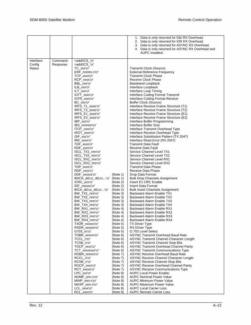
SDM-8000 Satellite Modem Remote Control Operation
Rev. 12 A–21
1. Data is only returned for D&I RX Overhead.2. Data is only returned for IDR RX Overhead.3. Data is only returned for ASYNC RX Overhead.4. Data is only returned for ASYNC RX Overhead and
AUPC installed.
InterfaceConfigStatus
Command:Response:
<add/ICS_'cr'>add/ICS_'cr'TC_xxx'cr'ERF_nnnnn.n'cr'TCP_xxxx'cr'RCP_xxxx'cr'BBL_xxx'cr'ILB_xxx'cr'ILT_xxx'cr'ICFT_xxxx'cr'ICFR_xxxx'cr'BC_xxx'cr'IRFS_T1_ssss'cr'IRFS_T2_ssss'cr'IRFS_E1_ssss'cr'IRFS_E2_ssss'cr'IBP_xxx'cr'IBS_nnnnnn'cr'ITOT_xxxx'cr'IROT_xxxx'cr'ISP_xxx'cr'IRE_xxxx'cr'TDF_xxxx'cr'RDF_xxxx'cr'ISCL_TX1_nnn'cr'ISCL_TX2_nnn'cr'ISCL_RX1_nnn'cr'ISCL_RX2_nnn'cr'TDP_xxxx'cr'RDP_xxxx'cr'DDF_xxxxxx'cr' (Note 1)BDCA_dd;cc_dd;cc...'cr' (Note 1)ICRC_xxx'cr' (Note 2)IDF_xxxxxx'cr' (Note 2)BICA_dd;cc_dd;cc...'cr' (Note 2)BW_TX1_nnn'cr' (Note 3)BW_TX2_nnn'cr' (Note 3)BW_TX3_nnn'cr' (Note 3)BW_TX4_nnn'cr' (Note 3)BW_RX1_nnn'cr' (Note 4)BW_RX2_nnn'cr' (Note 4)BW_RX3_nnn'cr' (Note 4)BW_RX4_nnn'cr' (Note 4)TXDR_xxxxxx'cr' (Note 5)RXDR_xxxxxx'cr' (Note 5)G703_xx'cr' (Note 5)TOBR_nnnnn'cr' (Note 6)TCCL_n'cr' (Note 6)TCSB_n'cr' (Note 6)TOCP_xxxx'cr' (Note 6)TCT_xxxxxxxx'cr' (Note 6)ROBR_nnnnn'cr' (Note 7)RCCL_n'cr' (Note 7)RCSB_n'cr' (Note 7)ROCP_xxxx'cr' (Note 7)RCT_xxxxx'cr' (Note 7)LPC_xxx'cr' (Note 8)NOMP_snn.n'cr' (Note 8)MINP_snn.n'cr' (Note 8)MAXP_snn.n'cr' (Note 8)LCL_xxxx'cr' (Note 8)RCL_xxxx'cr' (Note 8)
Transmit Clock (Source)External Reference FrequencyTransmit Clock PhaseReceive Clock PhaseBaseband LoopbackInterface LoopbackInterface Loop TimingInterface Coding Format TransmitInterface Coding Format ReceiveBuffer Clock (Source)Interface Receive Frame Structure (T1)Interface Receive Frame Structure (T2)Interface Receive Frame Structure (E1)Interface Receive Frame Structure (E2)Interface Buffer ProgrammingInterface Buffer SizeInterface Transmit Overhead TypeInterface Receive Overhead TypeInterface Substitution Pattern (TX 2047)Interface Read Error (RX 2047)Transmit Data FaultReceive Data FaultService Channel Level TX1Service Channel Level TX2Service Channel Level RX1Service Channel Level RX2Transmit Data PhaseReceive Data PhaseDrop Data FormatBulk Drop Channels AssignmentInsert E1 CRC EnableInsert Data FormatBulk Insert Channels AssignmentBackward Alarm Enable TX1Backward Alarm Enable TX2Backward Alarm Enable TX3Backward Alarm Enable TX4Backward Alarm Enable RX1Backward Alarm Enable RX2Backward Alarm Enable RX3Backward Alarm Enable RX4TX Driver TypeRX Driver TypeG.703 Level SelectASYNC Transmit Overhead Baud RateASYNC Transmit Channel Character LengthASYNC Transmit Channel Stop BitsASYNC Transmit Overhead Channel ParityASYNC Transmit Communications TypeASYNC Receive Overhead Baud RateASYNC Receive Channel Character LengthASYNC Receive Channel Stop BitsASYNC Receive Overhead Channel ParityASYNC Receive Communications TypeAUPC Local Power EnableAUPC Nominal Power ValueAUPC Minimum Power ValueAUPC Maximum Power ValueAUPC Local Carrier LossAUPC Remote Carrier Loss

Remote Control Operation SDM-8000 Satellite Modem
A–22 Rev. 12
ENSP_nn.n'cr' (Note 9)MAXT_n.n'cr' (Note 9)TDVB_xxxx'cr' (Note 10)RDVB_xxxx'cr' (Note 10)ESCT_xxxxx’cr’’lf’] (Note 5)
AUPC Eb/N0 Target Set PointAUPC Maximum Tracking RateTransmit DVB FramingReceive DVB FramingIDR ESC Type
The interface configuration status command causes a block ofdata to be returned by the addressed modem. The blockreflects the current configuration of the interface. Additionalconfiguration status of new options and features will always beappended to the end.
Notes:1. Data is only returned for D&I TX Overhead.2. Data is only returned for D&I RX Overhead.3. Data is only returned for IDR TX Overhead.4. Data is only returned for IDR RX Overhead.5. Data is only returned if the relay board option is
installed on the interface board.6. Data is only returned for ASYNC TX Overhead.7. Data is only returned for ASYNC RX Overhead.8. Data is only returned for ASYNC TX Overhead and
AUPC installed.9. Data is only returned for ASYNC RX Overhead and
AUPC installed.10. DVB Reed-Solomon board must be installed.
MODEMFaultsStatus(Summary)
Command:Response:
<add/MFS_'cr'>add/MFS_'cr'DMD_xxx'cr'MOD_xxx'cr'ITX_xxx'cr'IRX_xxx'cr'CEQ_xxx'cr'BWAL_xxx'cr'lf']
Demodulator (FLT/OK)Modulator (FLT/OK)Interface Transmit Side (FLT/OK)Interface Receive Side (FLT/OK)Common Equipment (FLT/OK)Backward Alarms (FLT/OK)
ModulatorStatus
Command:Response:
<add/MS_'cr'>add/MS_'cr'RF_xxx'cr'MOD_xxx'cr'SYN_xxx'cr'DCA_xxx'cr'DCS_xxx'cr'ICH_xxx'cr'QCH_xxx'cr'AGC_xxx'cr'SCT_xxx'cr'EXT_xxx'cr'PROG_xxx'cr'CONF_xxx'cr'SFLT_xx'cr''lf']
RF Output (ON/OFF) Actual Status Not ConfigModule (OK/FLT)IF Synthesizer (OK/FLT)Data Clock Activity (OK/FLT)Data Clock Synthesizer (OK/FLT)I Channel (OK/FLT)Q Channel (OK/FLT)AGC Level (OK/FLT)Internal SCT Synthesizer (OK/FLT)External Reference Activity (OK/FLT)Programming (OK/FLT)Configuration (OK/FLT)Number of Stored Faults Logged (0 to 10)
Demodulator Status
Command:Response:
<add/DS_'cr'>add/DS_'cr'MOD_xxx'cr'CD_xxx'cr'SYN_xxx'cr'RCS_xxx'cr'ICH_xxx'cr'QCH_xxx'cr'DSCR_xxx'cr'BERT_xxx'cr'PROG_xxx'cr'CONF_xxx'cr'SFLT_xx'cr''lf']
Demod Module (OK/FLT)Carrier Detect (OK/FLT)IF Synthesizer Lock (OK/FLT)Receive Clock Synthesizer (OK/FLT)I Channel (OK/FLT)Q Channel (OK/FLT)Descrambler (OK/FLT)BER Threshold (OK/FLT)Programming (OK/FLT)Configuration (OK/FLT)Number of Stored Faults Logged (0 to 10)

SDM-8000 Satellite Modem Remote Control Operation
Rev. 12 A–23
InterfaceTransmitSide Status
Command:Response:
<add/ITXS_'cr'>add/ITXS_'cr'DDRP_xxx'cr'TXD_xxx'cr'PLL_xxx'cr'CLK_xxx'cr'PROG_xxx'cr'CONF_xxx'cr'SFLT_xx'cr''lf']
D&I Drop (OK/FLT)Transmit Data/AIS (OK/FLT)Transmit Synthesizer PLL Lock (OK/FLT)Selected Transmit Clock Activity (OK/FLT)Programming (OK/FLT)Configuration (OK/FLT)Number of Stored Faults Logged (0 to 10)
InterfaceReceiveSide Status
Command:Response:
<add/IRXS_'cr'>add/IRXS_'cr'UNFL_xxx'cr'OVFL_xxx'cr'RXD_xxx'cr'FBER_xxx'cr'BWA_xxx'cr'CLK_xxx'cr'PLL_xxx'cr'DMUX_xxx'cr'2047_xxx'cr'BUFF_xxx'cr'INS_xxx'cr'PROG_xxx'cr'CONF_xxx'cr'SFLT_xx'cr''lf']
Buffer Underflow (OK/FLT)Buffer Overflow (OK/FLT)Receive Data Loss/AIS (OK/FLT)Frame BER (OK/FLT)Receive Backward Alarm (OK/FLT)Selected Buffer Clock Activity (OK/FLT)Buffer Clock PLL Lock (OK/FLT)Demux Lock (OK/FLT)2047 Pattern Lock Detect (OK/FLT)Buffer Full (OK/FLT)D&I Insert (OK/FLT)Programming (OK/FLT)Configuration (OK/FLT)Number of Stored Faults Logged (0 to 10)
CommonEquipmentStatus
Command:Response:
<add/CES_'cr'>add/CES_'cr'M&C_xxx'cr'INT_xxx'cr'BAT_xxx'cr'+5_xxx'cr'-5_xxx'cr'+12_xxx'cr'-12_xxx'cr'MODE_xxxxxx'cr'SFLT_xx'cr''lf']
Monitor & Control Module (OK/FLT)Data Interface Module (OK/FLT)Battery/Clock (OK/FLT)+5V Power Supply (OK/FLT)-5V Power Supply (OK/FLT)+12V Power Supply (OK/FLT)-12V Power Supply (OK/FLT)Mode (LOCAL or REMOTE)Number of Stored Faults Logged (0 to 10)
The common equipment status command causes a block ofdata to be returned which indicates the status of the commonequipment.
InterfaceAlarms(BackwardAlarm)Status
Command:Response:
<add/IAS_'cr'>add/IAS_'cr'TXBWA1_xxx'cr'TXBWA2_xxx'cr'TXBWA3_xxx'cr'TXBWA4_xxx'cr'RXBWA1_xxx'cr'RXBWA2_xxx'cr'RXBWA3_xxx'cr'RXBWA4_xxx'cr'SFLT_xx'cr''lf']
TX Backward Alarm 1 (FLT/OK)TX Backward Alarm 2 (FLT/OK)TX Backward Alarm 3 (FLT/OK)TX Backward Alarm 4 (FLT/OK)RX Backward Alarm 1 (FLT/OK)Backward Alarm 2 (FLT/OK)RX Backward Alarm 3 (FLT/OK)RX Backward Alarm 4 (FLT/OK)Number of Stored Faults Logged (0 to 10)
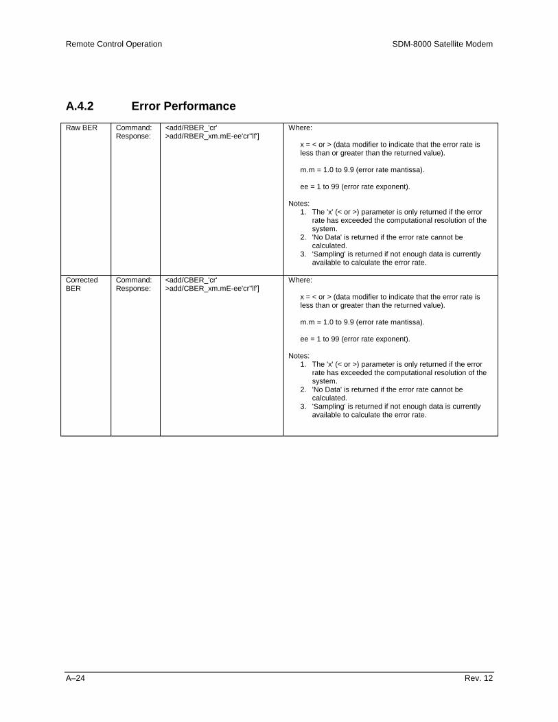
Remote Control Operation SDM-8000 Satellite Modem
A–24 Rev. 12
A.4.2 Error PerformanceRaw BER Command:
Response:<add/RBER_'cr'>add/RBER_xm.mE-ee'cr''lf']
Where:
x = < or > (data modifier to indicate that the error rate isless than or greater than the returned value).
m.m = 1.0 to 9.9 (error rate mantissa).
ee = 1 to 99 (error rate exponent).
Notes:1. The 'x' (< or >) parameter is only returned if the error
rate has exceeded the computational resolution of thesystem.
2. 'No Data' is returned if the error rate cannot becalculated.
3. 'Sampling' is returned if not enough data is currentlyavailable to calculate the error rate.
CorrectedBER
Command:Response:
<add/CBER_'cr'>add/CBER_xm.mE-ee'cr''lf']
Where:
x = < or > (data modifier to indicate that the error rate isless than or greater than the returned value).
m.m = 1.0 to 9.9 (error rate mantissa).
ee = 1 to 99 (error rate exponent).
Notes:1. The 'x' (< or >) parameter is only returned if the error
rate has exceeded the computational resolution of thesystem.
2. 'No Data' is returned if the error rate cannot becalculated.
3. 'Sampling' is returned if not enough data is currentlyavailable to calculate the error rate.
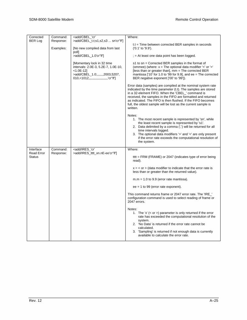
SDM-8000 Satellite Modem Remote Control Operation
Rev. 12 A–25
CorrectedBER Log
Command:Response:
Examples:
<add/CBEL_'cr'>add/CBEL_t.t;s1,s2,s3 ... sn'cr''lf']
[No new compiled data from lastpoll]>add/CBEL_1.0'cr''lf']
[Momentary lock in 32 timeintervals: 2.0E-3, 5.2E-7, 1.0E-10,<1.0E-12]>add/CBEL_1.0;,,,,,,,2003,5207,010,<1012,,,,,,,,,,,,,,,,,,,,,'cr''lf']
Where:
t.t = Time between corrected BER samples in seconds('0.1' to '9.9').
; = At least one data point has been logged.
s1 to sn = Corrected BER samples in the format of(xmmee) (where: x = The optional data modifier '<' or '>'[less than or greater than], mm = The corrected BERmantissa ['10' for 1.0 to '99 for 9.9], and ee = The correctedBER negative exponent ['00' to '99']).
Error data (samples) are compiled at the nominal system rateindicated by the time parameter (t.t). The samples are storedin a 32-element FIFO. When the 'CBEL_' command isreceived, the samples in the FIFO are formatted and returnedas indicated. The FIFO is then flushed. If the FIFO becomesfull, the oldest sample will be lost as the current sample iswritten.
Notes:1. The most recent sample is represented by 'sn', while
the least recent sample is represented by 's1'.2. Data delimited by a comma (',') will be returned for all
time intervals logged.3. The optional data modifiers '>' and '<' are only present
if the error rate exceeds the computational resolution ofthe system.
InterfaceRead ErrorStatus
Command:Response:
<add/IRES_'cr'>add/IRES_tttt_xn.nE-ee'cr''lf']
Where:
tttt = FRM (FRAME) or 2047 (indicates type of error beingread).
x = < or > (data modifier to indicate that the error rate isless than or greater than the returned value).
m.m = 1.0 to 9.9 (error rate mantissa).
ee = 1 to 99 (error rate exponent).
This command returns frame or 2047 error rate. The 'IRE_'configuration command is used to select reading of frame or2047 errors.
Notes:1. The 'x' (< or >) parameter is only returned if the error
rate has exceeded the computational resolution of thesystem.
2. 'No Data' is returned if the error rate cannot becalculated.
3. 'Sampling' is returned if not enough data is currentlyavailable to calculate the error rate.
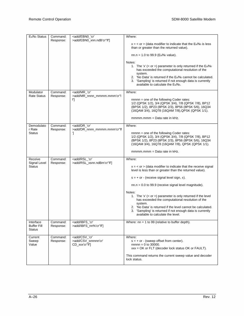
Remote Control Operation SDM-8000 Satellite Modem
A–26 Rev. 12
Eb/N0 Status Command:Response:
<add/EBN0_'cr'>add/EBN0_xnn.ndB'cr''lf']
Where:
x = < or > (data modifier to indicate that the Eb/N0 is lessthan or greater than the returned value).
nn.n = 1.0 to 99.9 (Eb/N0 value).
Notes:1. The 'x' (< or >) parameter is only returned if the Eb/N0
has exceeded the computational resolution of thesystem.
2. 'No Data' is returned if the Eb/N0 cannot be calculated.3. 'Sampling' is returned if not enough data is currently
available to calculate the Eb/N0.
ModulatorRate Status
Command:Response:
<add/MR_'cr'>add/MR_nnnn_mmmm.mmm'cr''lf']
Where:
nnnnn = one of the following Coder rates:1/2 (QPSK 1/2), 3/4 (QPSK 3/4), 7/8 (QPSK 7/8), BP12(BPSK 1/2), 8P23 (8PSK 2/3), 8P56 (8PSK 5/6), 16Q34(16QAM 3/4), 16Q78 (16QAM 7/8),QPSK (QPSK 1/1).
mmmm.mmm = Data rate in kHz.
Demodulator RateStatus
Command:Response:
<add/DR_'cr'>add/DR_nnnn_mmmm.mmm'cr''lf']
Where:
nnnnn = one of the following Coder rates:1/2 (QPSK 1/2), 3/4 (QPSK 3/4), 7/8 (QPSK 7/8), BP12(BPSK 1/2), 8P23 (8PSK 2/3), 8P56 (8PSK 5/6), 16Q34(16QAM 3/4), 16Q78 (16QAM 7/8), QPSK (QPSK 1/1).
mmmm.mmm = Data rate in kHz.
ReceiveSignal LevelStatus
Command:Response:
<add/RSL_'cr'>add/RSL_xsnn.ndBm'cr''lf']
Where:
x = < or > (data modifier to indicate that the receive signallevel is less than or greater than the returned value).
s = + or - (receive signal level sign, ±).
nn.n = 0.0 to 99.9 (receive signal level magnitude).
Notes:1. The 'x' (< or >) parameter is only returned if the level
has exceeded the computational resolution of thesystem.
2. 'No Data' is returned if the level cannot be calculated.3. 'Sampling' is returned if not enough data is currently
available to calculate the level.
InterfaceBuffer FillStatus
Command:Response:
<add/IBFS_'cr'>add/IBFS_nn%'cr''lf']
Where: nn = 1 to 99 (relative to buffer depth).
CurrentSweepValue
Command:Response:
<add/CSV_'cr'>add/CSV_snnnnn'cr'CD_xxx'cr''lf']
Where:s = + or - (sweep offset from center).nnnnn = 0 to 30000.xxx = OK or FLT (decoder lock status OK or FAULT).
This command returns the current sweep value and decoderlock status.
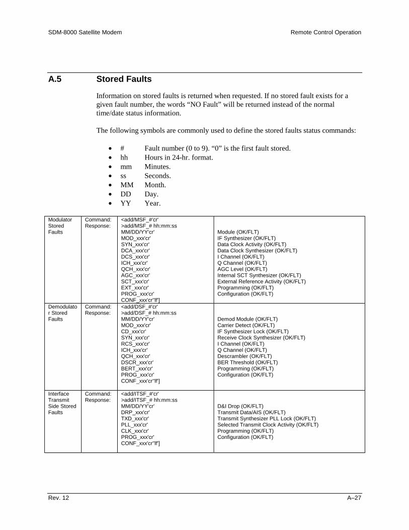
SDM-8000 Satellite Modem Remote Control Operation
Rev. 12 A–27
A.5 Stored Faults
Information on stored faults is returned when requested. If no stored fault exists for agiven fault number, the words “NO Fault” will be returned instead of the normaltime/date status information.
The following symbols are commonly used to define the stored faults status commands:
• # Fault number (0 to 9). “0” is the first fault stored.• hh Hours in 24-hr. format.• mm Minutes.• ss Seconds.• MM Month.• DD Day.• YY Year.
ModulatorStoredFaults
Command:Response:
<add/MSF_#'cr'>add/MSF_# hh:mm:ssMM/DD/YY'cr'MOD_xxx'cr'SYN_xxx'cr'DCA_xxx'cr'DCS_xxx'cr'ICH_xxx'cr'QCH_xxx'cr'AGC_xxx'cr'SCT_xxx'cr'EXT_xxx'cr'PROG_xxx'cr'CONF_xxx'cr''lf']
Module (OK/FLT)IF Synthesizer (OK/FLT)Data Clock Activity (OK/FLT)Data Clock Synthesizer (OK/FLT)I Channel (OK/FLT)Q Channel (OK/FLT)AGC Level (OK/FLT)Internal SCT Synthesizer (OK/FLT)External Reference Activity (OK/FLT)Programming (OK/FLT)Configuration (OK/FLT)
Demodulator StoredFaults
Command:Response:
<add/DSF_#'cr'>add/DSF_# hh:mm:ssMM/DD/YY'cr'MOD_xxx'cr'CD_xxx'cr'SYN_xxx'cr'RCS_xxx'cr'ICH_xxx'cr'QCH_xxx'cr'DSCR_xxx'cr'BERT_xxx'cr'PROG_xxx'cr'CONF_xxx'cr''lf']
Demod Module (OK/FLT)Carrier Detect (OK/FLT)IF Synthesizer Lock (OK/FLT)Receive Clock Synthesizer (OK/FLT)I Channel (OK/FLT)Q Channel (OK/FLT)Descrambler (OK/FLT)BER Threshold (OK/FLT)Programming (OK/FLT)Configuration (OK/FLT)
InterfaceTransmitSide StoredFaults
Command:Response:
<add/ITSF_#'cr'>add/ITSF_# hh:mm:ssMM/DD/YY'cr'DRP_xxx'cr'TXD_xxx'cr'PLL_xxx'cr'CLK_xxx'cr'PROG_xxx'cr'CONF_xxx'cr''lf']
D&I Drop (OK/FLT)Transmit Data/AIS (OK/FLT)Transmit Synthesizer PLL Lock (OK/FLT)Selected Transmit Clock Activity (OK/FLT)Programming (OK/FLT)Configuration (OK/FLT)
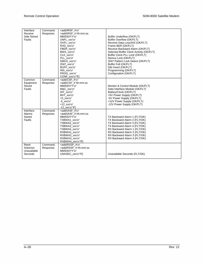
Remote Control Operation SDM-8000 Satellite Modem
A–28 Rev. 12
InterfaceReceiveSide StoredFaults
Command:Response:
<add/IRSF_#'cr'>add/IRSF_# hh:mm:ssMM/DD/YY'cr'UNFL_xxx'cr'OVFL_xxx'cr'RXD_xxx'cr'FBER_xxx'cr'BWA_xxx'cr'CLK_xxx'cr'PLL_xxx'cr'DMUX_xxx'cr'2047_xxx'cr'BUFF_xxx'cr'INS_xxx'cr'PROG_xxx'cr'CONF_xxx'cr''lf']
Buffer Underflow (OK/FLT)Buffer Overflow (OK/FLT)Receive Data Loss/AIS (OK/FLT)Frame BER (OK/FLT)Receive Backward Alarm (OK/FLT)Selected Buffer Clock Activity (OK/FLT)Buffer Clock PLL Lock (OK/FLT)Demux Lock (OK/FLT)2047 Pattern Lock Detect (OK/FLT)Buffer Full (OK/FLT)D&I Insert (OK/FLT)Programming (OK/FLT)Configuration (OK/FLT)
CommonEquipmentStoredFaults
Command:Response:
<add/CSF_#'cr'>add/CSF_# hh:mm:ssMM/DD/YY'cr'M&C_xxx'cr'INT_xxx'cr'BAT_xxx'cr'+5_xxx'cr'-5_xxx'cr'+12_xxx'cr'-12_xxx'cr''lf']
Monitor & Control Module (OK/FLT)Data Interface Module (OK/FLT)Battery/Clock (OK/FLT)+5V Power Supply (OK/FLT)-5V Power Supply (OK/FLT)+12V Power Supply (OK/FLT)-12V Power Supply (OK/FLT)
InterfaceAlarmsStoredFaults
Command:Response:
<add/IASF_#'cr'>add/IASF_# hh:mm:ssMM/DD/YY'cr'TXBWA1_xxx'cr'TXBWA2_xxx'cr'TXBWA3_xxx'cr'TXBWA4_xxx'cr'RXBWA1_xxx'cr'RXBWA2_xxx'cr'RXBWA3_xxx'cr'RXBWA4_xxx'cr''lf']
TX Backward Alarm 1 (FLT/OK)TX Backward Alarm 2 (FLT/OK)TX Backward Alarm 3 (FLT/OK)TX Backward Alarm 4 (FLT/OK)RX Backward Alarm 1 (FLT/OK)RX Backward Alarm 2 (FLT/OK)RX Backward Alarm 3 (FLT/OK)RX Backward Alarm 4 (FLT/OK)
Reed-SolomonUnavailableSeconds
Command:Response:
<add/RSSF_#'cr'>add/RSSF_# hh:mm:ssMM/DD/YY'cr'UNASEC_xxx'cr''lf'] Unavailable Seconds (FLT/OK)

SDM-8000 Satellite Modem Remote Control Operation
Rev. 12 A–29
Bulk ConsolAnalogStatus
Command:Response:
<add/BCAS_'cr'>add/BCAS_p1,p2,p3, . . . pn'cr''lf']
This command is similar to the 'BCS_' command, butreturns modem analog parameters. Additional status of newoptions and features will always be appended to the end.
Where 'pn' is the last parameter returned.
ParameterNumber
Parameter Name(Command Reference) Description
1
2
3
4
5
6
Receive Signal Level(ref. 'RSL_' command).
Raw BER(ref. 'RBER_' command).
Corrected BER(ref. 'CBER_' command).
Interface Read Error Status(ref. 'IRES_' command).
Eb/N0
(ref. 'EBN0_' command).
Buffer Fill Status(ref. 'IBFS_' command).
p1 = xsnn.n, receive signal level in dBm.
p2 = xm.m-ee.
p3 = xm.m-ee.
p4 = tttt_xm.m-ee.
p5 = xnn.n, Eb/N0 in dB.
p6 = nn%, buffer fill status.
Notes:1. Parameters 2 through 6 are dependent on carrier acquisition, if the decoder is not locked empty data blocks are returned
(,,,,,).2. Parameter 4 will return null data for DVB RX Overhead.

Remote Control Operation SDM-8000 Satellite Modem
A–30 Rev. 12
Bulk ConsolStatus
Command:Response:
<add/BCS_'cr'>add/BCS_p1,p2,p3, . . . pn'cr''lf']
This command causes bulk modem status to be returned.To reduce the length of the response, message parameterdata are returned without identifiers. However, parameteridentification can be determined by order of return. Eachstatus parameter is terminated with a ',' (comma), except forthe last parameter, which has the standard messagetermination sequence ('cr''lf']). Most of the data returned isformatted the same way as the single command statusrequest (refer to the appropriate portions of this document inpreceding sections). Additional configuration status of newoptions and features will always be appended to the end.
Where 'pn' is the last parameter returned.
ParameterNumber
Parameter Name(Command Reference) Description
1
2
3
4
5
6
7
8
9
10
11
12
13
14
15
16
Modulator RF output(ref. 'RF_' command).
Modulator IF frequency(ref. 'MF_' command).
Modulator rate(ref. 'MR_' command).
Modulator preset 'A' assignment(ref. 'ARMA_' command).
Modulator preset 'B' assignment(ref. 'ARMB_' command).
Modulator preset 'C' assignment(ref. 'ARMC_' command).
Modulator preset 'D' assignment(ref. 'ARMD_' command).
Modulator preset 'V' assignment(ref. 'ARMV_' command).
Modulator power offset(ref. 'MPO_' command).
Modulator output power level(ref. 'MOP_' command).
Scrambler enable(ref. 'SE_' command).
Differential encoder enable(ref. 'DENC_' command).
Modulator type(ref. 'MT_' command).
Modulator encoder type(ref. 'MET_' command).
Carrier only mode ON/OFF.
Demodulator IF frequency(ref. 'DF_' command).
p1 = n, where 'n' is '0' (off) or '1' (on).
p2 = nnn.nnnn, IF frequency in MHz.
p3 = nnnnn_mmmm.mmm, code rate/data rate in kbit/s.
p4 = nnnnn_mmmm.mmm, code rate/data rate in kbit/s.
p5 = nnnnn_mmmm.mmm, code rate/data rate in kbit/s.
p6 = nnnnn_mmmm.mmm, code rate/data rate in kbit/s.
p7 = nnnnn_mmmm.mmm, code rate/data rate in kbit/s.
p8 = nnnnn_mmmm.mmm, code rate/data rate in kbit/s.
p9 = snn.n, modulator power offset in dB.
p10 = snn.n, transmitter output power level in dBm.
p11 = n, where 'n' is '0' (off) or '1' (on).
p12 = n, where 'n' is '0' (off) or '1' (on).
p13 = n, where 'n' is '0' (EFD), '1' (INTL), '3' (FDC), or '4'(CSC).
p14 = n, where 'n' is '0' (SEQ) or '1' (VIT).
p15 = n, where 'n' is '0' (off) or '1' (on).
p16 = nnn.nnnn, demodulator IF frequency in MHz.

SDM-8000 Satellite Modem Remote Control Operation
Rev. 12 A–31
Bulk ConsolStatus(continued)
ParameterNumber
Parameter Name(Command Reference) Description
17
18
19
20
21
22
23
24
25
26
27
28
29
30
31
32
33
34
35
Demodulator rate(ref. 'DR_' command).
Demodulator preset A assignment(ref. 'ADRA_' command).
Demodulator preset B assignment(ref. 'ADRB_' command).
Demodulator preset C assignment(ref. 'ADRC_' command).
Demodulator preset D assignment(ref. 'ADRD_' command).
Demodulator preset V assignment(ref. 'ADRV_' command).
Descrambler enable(ref. 'DE_' command).
Differential decoder enable(ref. 'DDEC_' command).
RF loopback(ref. 'RFL_' command).
IF loopback(ref. 'IFL_' command).
Sweep center frequency(ref. 'SCF_' command).
Sweep width range(ref. 'SWR_' command).
Sweep reacquisitionref. 'SR_' command).
BER threshold(ref. 'BERT_' command).
Demodulator type(ref. 'DT_' command).
Demodulator decoder type(ref. 'DDT_' command).
Transmit clock source(ref. 'TC_' command).
External reference frequency(ref. 'ERF_' command).
Transmit clock phase(ref. 'TCP_' command).
p17 = nnnnn_mmmm.mmm, code rate/data rate in kbit/s.
p18 = nnnnn_mmmm.mmm, code rate/data rate in kbit/s.
p19 = nnnnn_mmmm.mmm, code rate/data rate in kbit/s.
p20 = nnnnn_mmmm.mmm, code rate/data rate in kbit/s.
p21 = nnnnn_mmmm.mmm, code rate/data rate in kbit/s.
p22 = nnnnn_mmmm.mmm, code rate/data rate in kbit/s.
p23 = n, where 'n' is '0' (off) or '1' (on).
p24 = n, where 'n' is '0' (off) or '1' (on).
p25 = n, where 'n' is '0' (off) or '1' (on).
p26 = n, where 'n' is '0' (off) or '1' (on).
p27 = snnnnn, sweep center frequency in Hz.
p28 = nnnnn, sweep range in Hz.
p29 = nnn, reacquisition time in seconds.
p30 = xxxx, BER threshold.
p31 = n, where 'n' is '0' (EFD), '1' (INTL), '3' (FDC), or '4'(CSC).
p32 = n, where 'n' is '0' (SEQ) or '1' (VIT).
p33 = n, where 'n' is '0' (INT), '1' (REF), or '2' (EXT).
p34 = nnnnn.n, external reference frequency in kHz.
p35 = n, where 'n' is '0' (NRM), '1' (INV), or '2' (AUTO).

Remote Control Operation SDM-8000 Satellite Modem
A–32 Rev. 12
Bulk ConsolStatus(continued)
ParameterNumber
Parameter Name(Command Reference) Description
36
37
38
39
40
41
42
43
44
45
46
47
48
49
50
51
52
53
54
Receive clock phase(ref. 'RCP_' command).
Baseband loopback(ref. 'BBL_' command).
Interface loopback(ref. 'ILB_' command).
Interface loop timing(ref. 'ILT_' command).
TX Interface coding format(ref. 'ICFT_' command).
RX Interface coding format(ref. 'ICFR_' command).
Buffer clock source(ref. 'BC_' command).
Interface RX-T1 frame structure(ref. 'IRFS_' command).
Interface RX-T2 frame structure(ref. 'IRFS_' command).
Interface RX-E1 frame structure(ref. 'IRFS_' command).
Interface RX-E2 frame structure(ref. 'IRFS_' command).
Interface Buffer Programming(ref. 'IBP_' command).
Interface buffer size(ref 'IBS_' command)..Interface transmit overhead type(ref. 'ITOT_' command).
Interface receive overhead type(ref. 'IROT_' command).
Interface substitution pattern(ref. 'ISP_' command).
Interface read error(ef. 'IRE_' command).
Transmit data fault(ref. 'TDF_' command).
Receive data fault(ref. 'RDF_' command).
p36 = n, where 'n' is '0' (NRM) or '1' (INV).
p37 = n, where 'n' is '0' (off) or '1' (on).
p38 = n, where 'n' is '0' (off) or '1' (on).
p39 = n, where 'n' is '0' (off) or '1' (on).
p40 = n, where 'n' is '0' (AMI), '1' (B6ZS), '2' (B8ZS), or '3'(HDB3).
p41 = n, where 'n' is '0' (AMI), '1' (B6ZS), '2' (B8ZS), or '3'(HDB3).
p42 = n, where 'n' is '0' (INT), '1' (REF), '2' (EXT), '3' (SAT),'4' (HS ), or 5 (INS).
p43 = n, where n is '0' (NONE) or '1' (G704).
p44 = n, where n is '0' (NONE), '1' (G704), '3' (G743), or '5'(G747).
p45 = n, where n is '0' (NONE) or '1' (G704).
p46 = n, where n is '0' (NONE), '1' (G704), '2' (G74), or '4'(G745).
p47 = n, where 'n' is '0' (BITS) or '1' (MS).
p48 = nnnnnn, buffer size in bits or milli seconds.
p49 = n, where 'n' is '0' (NONE), '1' (IDR), '2' (IBS), '3' (DI),'4' (ASYNC), or '5' (DVB).
p50 = n, where 'n' is '0' (NONE), '1' (IDR), '2' (IBS), '3' (DI),'4' (ASYNC), or '5' (DVB).
p51 = n, where 'n' is '0' (off) or '1' (on).
p52 = n, where 'n' is '0' (FRM/OFF) or '1' (2047/ON).
p53 = n, where 'n' is '0' (NONE), '1' (DATA), or '2' (AIS).
p54 = n, where 'n' is '0' (NONE), '1' (DATA), or '2' (AIS).
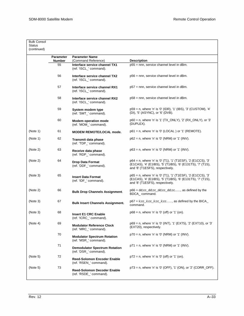
SDM-8000 Satellite Modem Remote Control Operation
Rev. 12 A–33
Bulk ConsolStatus(continued)
ParameterNumber
Parameter Name(Command Reference) Description
(Note 1)
(Note 1)
(Note 2)
(Note 2)
(Note 3)
(Note 2)
(Note 3)
(Note 3)
(Note 4)
(Note 5)
(Note 5)
55
56
57
58
59
60
61
62
63
64
65
66
67
68
69
70
71
72
73
Interface service channel TX1(ref. 'ISCL_' command).
Interface service channel TX2(ref. 'ISCL_' command).
Interface service channel RX1(ref. 'ISCL_' command).
Interface service channel RX2(ref. 'ISCL_' command).
System modem type(ref. 'SMT_' command).
Modem operation mode(ref. 'MOM_' command).
MODEM REMOTE/LOCAL mode.
Transmit data phase(ref. 'TDP_' command).
Receive data phase(ref. 'RDP_' command).
Drop Data Format(ref. 'DDF_' command).
Insert Data Format(ref. 'IDF_' command).
Bulk Drop Channels Assignment.
Bulk Insert Channels Assignment.
Insert E1 CRC Enable(ref. 'ICRC_' command).
Modulator Reference Clock(ref. 'MRC_' command).
Modulator Spectrum Rotation(ref. 'MSR_' command).
Demodulator Spectrum Rotation(ref. 'DSR_' command).
Reed-Solomon Encoder Enable(ref. 'RSEN_' command).
Reed-Solomon Decoder Enable(ref. 'RSDE_' command).
p55 = nnn, service channel level in dBm.
p56 = nnn, service channel level in dBm.
p57 = nnn, service channel level in dBm.
p58 = nnn, service channel level in dBm.
p59 = n, where 'n' is '0' (IDR), '1' (IBS), '3' (CUSTOM), '4'(DI), '5' (ASYNC), or '6' (DVB).
p60 = n, where 'n' is '1' (TX_ONLY), '2' (RX_ONLY), or '3'(DUPLEX).
p61 = n, where 'n' is '0' (LOCAL ) or '1' (REMOTE).
p62 = n, where 'n' is '0' (NRM) or '1' (INV).
p63 = n, where 'n' is '0' (NRM) or '1' (INV).
p64 = n, where 'n' is '0' (T1), '1' (T1ESF), '2 (E1CCS), '3'(E1CAS), '4' (E1IBS), '5' (T1IBS), '6' (E131TS), '7' (T1S),and '8' (T1ESFS), respectively.
p65 = n, where 'n' is '0' (T1), '1' (T1ESF), '2 (E1CCS), '3'(E1CAS), '4' (E1IBS), '5' (T1IBS), '6' (E131TS), '7' (T1S),and '8' (T1ESFS), respectively.
p66 = dd;cc_dd;cc_dd;cc_dd;cc......, as defined by theBDCA_ command.
p67 = ii;cc_ii;cc_ii;cc_ii;cc......, as defined by the BICA_command.
p68 = n, where 'n' is '0' (off) or '1' (on).
p69 = n, where 'n' is '0' (INT), '1' (EXT5), '2' (EXT10), or '3'(EXT20), respectively.
p70 = n, where 'n' is '0' (NRM) or '1' (INV).
p71 = n, where 'n' is '0' (NRM) or '1' (INV).
p72 = n, where 'n' is '0' (off) or '1' (on).
p73 = n, where 'n' is '0' (OFF), '1' (ON), or '2' (CORR_OFF).

Remote Control Operation SDM-8000 Satellite Modem
A–34 Rev. 12
Bulk ConsolStatus(continued)
ParameterNumber
Parameter Name(Command Reference) Description
(Note 6)
(Note 6)
(Note 6)
(Note 7)
(Note 8)
(Note 7)
(Note 8)
(Note 7)
(Note 8)
(Note 7)
(Note 8)
74
75
76
77
78
79
80
81
82
83
84
85
86
87
88
89
90
91
92
Backward Alarm enable TX1(ref. 'BW_TX1_' command).
Backward Alarm enable TX2(ref. 'BW_TX2_' command).
Backward Alarm enable TX3(ref. 'BW_TX3_' command).
Backward Alarm enable TX4(ref. 'BW_TX4_' command).
Backward Alarm enable RX1(ref. 'BW_RX1_' command).
Backward Alarm enable RX2(ref. 'BW_RX2_' command).
Backward Alarm enable RX3(ref. 'BW_RX3_' command).
Backward Alarm enable RX4(ref. 'BW_RX4_' command).
TX Driver Type.
RX Driver Type(ref. 'RXDR_' command).
G703 Level Select(ref. 'G703_' command).
ASYNC TX Overhead Baud Rate(ref. 'TOBR_' command).
ASYNC RX Overhead Baud Rate(ref. 'ROBR_' command).
ASYNC TX Channel Char. Length(ref. 'TCCL_' command).
ASYNC RX Channel Char. Length(ref. 'RCCL_' command).
ASYNC TX Channel Stop Bits(ref. 'TCSB_' command).
ASYNC RX Channel Stop Bits(ref. 'RCSB_' command).
ASYNC TX Channel Parity(ref. 'TOCP_' command).
ASYNC RX Channel Parity(ref. 'ROCP_' command).
p74 = n, where 'n' is '0' (off) or '1' (on).
p75 = n, where 'n' is '0' (off) or '1' (on).
p76 = n, where 'n' is '0' (off) or '1' (on).
p77 = n, where 'n' is '0' (off) or '1' (on).
p78 = n, where 'n' is '0' (off) or '1' (on).
p79 = n, where 'n' is '0' (off) or '1' (on).
p80 = n, where 'n' is '0' (off) or '1' (on).
p81 = n, where 'n' is '0' (off) or '1' (on).
p82 = n, where 'n' is '0' (G.703), '1' (V.35), or '2'(MIL188/RS422).
p83 = n, where 'n' is '0' (G.703), '1' (V.35), or '2'(MIL188/RS422).
p84 = n, where 'n' is '0' (high drive), '1' (nominal), '2'(nominal shaped), '3' (low level), or '4' (low shaped).
p85 = nnnnn, where 'nnnnn' is the currently programmedbaud rate.
p86 = nnnnn, where 'nnnnn' is the currently programmedbaud rate.
p87 = n, where 'n' is the currently programmed characterlength.
p88 = n, where 'n' is the currently programmed characterlength.
p89 = n, where 'n' is the current number of stop bitsprogrammed.
p90 = n, where 'n' is the current number of stop bitsprogrammed.
p91 = xxxx, where 'xxxx' is the currently programmed parity.
p92 = xxxx, where 'xxxx' is the currently programmed parity.

SDM-8000 Satellite Modem Remote Control Operation
Rev. 12 A–35
Bulk ConsolStatus(continued)
ParameterNumber
Parameter Name(Command Reference) Description
(Note 7)
(Note 8)
(Note 9)
(Note 9)
(Note 9)
(Note 9)
(Note 10)
(Note 10)
(Note 9)
(Note 9)
(Note 11)
(Note 11)
(Note 6)
(Note 5)
(Note 5)
(Note 4)
93
94
95
96
97
98
99
100
101
102
103
104
105
106
107
108
ASYNC TX Communications Type(ref. 'TCT_' command).
ASYNC RX Communications Type(ref. 'RCT_' command).
AUPC Local Power enable ON/OFF(ref. 'LPC_' command).
AUPC Nominal Power Value(ref. 'NOMP_' command).
AUPC Minimum Power Value(ref. 'MINP_' command).
AUPC Maximum Power Value(ref. 'MAXP_' command).
AUPC EBN0 Target Set Point(ref. 'ENSP_' command).
AUPC Maximum Tracking Rate(ref. 'MAXT_' command).
AUPC Local Carrier Loss(ref. 'LCL_' command).
AUPC Remote Carrier Loss(ref. 'RCL_' command).
Transmit DVB Framing(ref. 'TDVB_' command).
Receive DVB Framing(ref. 'RDVB_' command)
IDR ESC Type(ref. "ESCT_" command).
TX 8PSK 2/3 IESS-310 Operation(ref. "T310_" command).
RX 8PSK 2/3 IESS-310 Operation(ref. "R310_" command).
Modulator SCT PLL Reference(ref. "MSPR_" command).
p93 = n, where 'n' is '0' (RS232), '1' (RS485_4WIRE), or '2'(RS485_2WIRE).
p94 = n, where 'n' is '0' (RS232) or '1' (RS485).
p95 = n, where 'n' is '0' (off) or '1' (on).
p96 = sYnn.n, where 'snn.n' Nominal Power Value in dBm.
p97 = snn.n, where 'snn.n' Minimum Power Value in dBm.
p98 = snn.n, where 'snn.n' Maximum Power Value in dBm.
p99 = nn.n, where 'nn.n' EBN0 Target Set Point in dB.
p100 = n.n, where 'n.n' is the Maximum Tracking Rate indB/Min.
p101 = n, where 'n' is '0' (HOLD), '1' (NOMINAL), or '2'(MAXIMUM).
p102 = n, where 'n' is '0' (HOLD), '1' (NOMINAL), or '2'(MAXIMUM).
p103 = n, where 'n' is '0' (188), '1' (204), or '2' (NONE)
p104 = n, where 'n' is '0' (188), '1' (204), or '2' (NONE).
p105 = n, where 'n' is '0' (AUDIO), '1' (DATA).
p106 = n, where 'n' is '0' (off) or '1' (on).
p107 = n, where 'n' is '0' (off) or '1' (on).
p108 = n, where 'n' is '0' (MODULATOR REF) or '1' (EXT-REF FREQ).

Remote Control Operation SDM-8000 Satellite Modem
A–36 Rev. 12
Notes:1. Data will only be returned with FW/24521-2 or higher on interface board. Comma is always returned.2. Data will only be returned if TX Overhead is programmed for Drop & Insert. Comma is always returned.3. Data will only be returned if RX Overhead is programmed for Drop & Insert. Comma is always returned.4. Data will only be returned if the modulator board has the High Stability Internal 5 MHz/External Divider Option. Comma is
always returned.5. Data will only be returned if the Reed-Solomon option is installed in the interface board. Comma is always returned.6. Data is only returned if the relay board option is installed on the interface board. Comma is always returned.7. Data will only be returned if TX Overhead is programmed for ASYNC. Comma is always returned.8. Data will only be returned if RX Overhead is programmed for ASYNC. Comma is always returned.9. Data will only be returned if TX Overhead is programmed for ASYNC and AUPC is installed. Comma is always returned.10. Data will only be returned if RX Overhead is programmed for ASYNC and AUPC is installed. Comma is always returned.11. DVB Reed-Solomon board must be installed.

SDM-8000 Satellite Modem Remote Control Operation
Rev. 12 A–37
Bulk ConsolStatus
Command:Response:
<add/BCSF_'cr'>add/BCSF_abcdefghijklmnop'cr''lf']
This command causes all modem fault status to bereturned. To reduce the length of the response, fault statusis embedded into the bit structure of the characters that arereturned. Faults are indicated by a binary 1 in thedesignated bit position. Additional fault status of newoptions and features will be appended to the end or useexisting reserved bits.
Character 'a': Modulator fault status character 1.Bit 6 = 1 always.Bit 5 = Modulator module fault.Bit 4 = RF output status, actual not programmed status(1 = on, 0 = off).Bit 3 through Bit 0 = Binary representation (0 to 10) ofthe number of modulator stored faults.
Character 'b': Modulator fault status character 2.Bit 6 = 1 always.Bit 5 = IF Synthesizer.Bit 4 = Data Clock Activity.Bit 3 = Data Clock Synthesizer.Bit 2 = I Channel.Bit 1 = Q Channel.Bit 0 = AGC Level.
Character 'c': Modulator fault status character 3.Bit 6 = 1 always.Bit 5 = Internal SCT Synthesizer.Bit 4 = Programming.Bit 3 = Configuration.Bit 2 = External Reference Activity.Bit 1 = reserved.Bit 0 = reserved.
Character 'd': Demodulator fault status character 1.Bit 6 = 1 always.Bit 5 = Demod module fault.Bit 4 = Carrier detect status (0 for decoder lock).Bit 3 through Bit 0 = Binary representation (0 to 10) ofthe number of demodulator stored faults.
Character 'e': Demodulator fault status character 2.Bit 6 = 1 always.Bit 5 = IF Synthesizer Lock.Bit 4 = Receive Clock Synthesizer.Bit 3 = I Channel.Bit 2 = Q Channel.Bit 1 = Descrambler.Bit 0 = BER threshold.
Character 'f': Demodulator fault status character 3.Bit 6 = 1 always.Bit 5 = Programming.Bit 4 = Configuration.Bit 3 = reserved.Bit 2 = reserved.Bit 1 = reserved.Bit 0 = reserved.
Character 'g': Interface transmit side faults character 1.Bit 6 = 1 always.Bit 5 = reserved.Bit 4 = reserved.Bit 3 through Bit 0 = Binary representation (0 to 10) ofthe number of interface transmit side stored faults.

Remote Control Operation SDM-8000 Satellite Modem
A–38 Rev. 12
Character 'h': Interface transmit side faults character 2.Bit 6 = 1 always.Bit 5 = Transmit Data/AIS.Bit 4 = Transmit Synthesizer PLL Lock.Bit 3 = Selected Transmit Clock Activity.Bit 2 = Programming.Bit 1 = Configuration.Bit 0 = Drop fault.
Character 'i': Interface receive side faults character 1.Bit 6 = 1 always.Bit 5 = Insert fault.Bit 4 = reserved.Bit 3 through Bit 0 = Binary representation (0 to 10) ofthe number of interface receive side stored faults.
Character 'j': Interface receive side faults character 2.Bit 6 = 1 always.Bit 5 = Buffer Underflow.Bit 4 = Buffer Overflow.Bit 3 = Receive Data Loss/AIS.Bit 2 = Frame BER.Bit 1 = Receive Backward Alarm.Bit 0 = Selected Buffer Clock Activity.
Character 'k': Interface receive side faults character 3.Bit 6 = 1 always.Bit 5 = Buffer Clock PLL Lock.Bit 4 = Demux Lock.Bit 3 = 2047 Pattern Lock Detect.Bit 2 = Buffer Full.Bit 1 = Programming.Bit 0 = Configuration.
Character 'l': Common equipment fault status character 1.Bit 6 = 1 always.Bit 5 = Monitor & Control Module.Bit 4 = Interface Module.Bit 3 through Bit 0 = Binary representation (0 to 10) ofthe number of common equipment stored faults.
Character 'm': Common equipment fault status character 2.Bit 6 = 1 always.Bit 5 = Battery/Clock.Bit 4 = +5V Power Supply.Bit 3 = -5V Power Supply.Bit 2 = +12V Power Supply.Bit 1 = -12V Power Supply.Bit 0 = reserved.
Character 'n': Interface backward alarm status character 1.Bit 6 = 1 always.Bit 5 = TX Backward Alarm 1.Bit 4 = TX Backward Alarm 2.Bit 3 through Bit 0 = Binary representation (0 to 10) ofthe number of backward alarm stored faults.
Character 'o': Interface backward alarm status character 2.Bit 6 = 1 always.Bit 5 = TX Backward Alarm 3.Bit 4 = TX Backward Alarm 4.Bit 3 = RX Backward Alarm 1.Bit 2 = RX Backward Alarm 2.Bit 1 = RX Backward Alarm 3.Bit 0 = RX Backward Alarm 4.
Character 'p': Interface Reed-Solomon Unavailable Seconds

SDM-8000 Satellite Modem Remote Control Operation
Rev. 12 A–39
Bit 6 = 1 always.Bit 5 = not used.Bit 4 = not used.Bit 3 through Bit 0 = Binary representation (0 to 10) ofthe number of Reed-Solomon Unavailable Secondsstored faults.
ChangeStatus
Command:Response:
<add/CS_'cr'>add/CS_x'cr''lf']
Where: The 'x' character is defined as follows:
'at' = no change since last BCS_ and BCSF_ polls.
'A' = BCS_ response has changed since last BCS_ poll
'B' = BCSF_ response has changed since last BCSF_poll
'C' = Both responses have changed since last BCS_ andBCSF_ polls.
This command indicates that a change has or has notoccurred on either the BCS_ or the BCSF_ response sincethe last BCS_ or BCSF_ poll.
EquipmentType
Command:Response:
<add/ET_'cr'>add/ET_tttttttt_xxx.yyy.zzz'cr''lf']
Where:tttttttt = Equipment type.xxx.yyy.zzz = Software version.
This command returns the equipment type and the softwareversion of the addressed device.
Monitor &ControlFirmwareInformation
Command:Response:
<add/MCFI_'cr'>add/MCFI_'cr'VER_xxx.yyy.zzz'cr'FW/nnnnnn-ddr'cr'mm/dd/yy'cr''lf']
Where:
xxx.yyy.zzz = Software version number (0.0.0 to999.999.999).
nnnnnn = Firmware number (0 to 999999).
dd = Firmware dash number (0 to 99).
r = Firmware revision (-, or A to Z).
ModulatorFirmwareInformation
Command:Response:
<add/MFI_'cr'>add/MFI_'cr'VER_xxx.yyy.zzz'cr'FW/nnnnnn-ddrr'cr'mm/dd/yy'cr'FPGA_FW/nnnnnn-ddrr'cr'FPGA_mm/dd/yy'cr''lf']
Where:
xxx.yyy.zzz = Software version number (0.0.0 to999.999.999).
nnnnnn = Firmware number (0 to 999999).
dd = Firmware dash number (0 to 99).
rr = Firmware revision (-, or A to Z).
Demodulator FirmwareInformation
Command:Response:
<add/DFI_'cr'>add/DFI_'cr'VER_xxx.yyy.zzz'cr'FW/nnnnnn-ddrr'cr'mm/dd/yy'cr'FPGA_FW/nnnnnn-ddrr'cr'FPGA_mm/dd/yy'cr''lf']
Where:
xxx.yyy.zzz = Software version number (0.0.0 to999.999.999).
nnnnnn = Firmware number (0 to 999999).
dd = Firmware dash number (0 to 99).
rr = Firmware revision (-, or A to Z).

Remote Control Operation SDM-8000 Satellite Modem
A–40 Rev. 12
InterfaceFirmwareInformation
Command:Response:
<add/IFI_'cr'>add/IFI_'cr'VER_xxx.yyy.zzz'cr'FW/nnnnnn-ddrr'cr'mm/dd/yy'cr'FPGA_FW/nnnnnn-ddrr'cr'FPGA_mm/dd/yy'cr''lf']
Where:
xxx.yyy.zzz = Software version number (0.0.0 to999.999.999).
nnnnnn = Firmware number (0 to 999999).
dd = Firmware dash number (0 to 99).
rr = Firmware revision (-, or A to Z).
ModemTypeCompatibility Status
Command:Response:
<add/MTCS_tttttt'cr'>add/MTCS_tttttt'cr's,INT_MODULE'cr's,TX_TERR_INT'cr's,RX_TERR_INT'cr's,MUX'cr's,DEMUX'cr's,BUFFER'cr's,IDR_TX_BWA'cr's,IDR_TX_ESC'cr's,IDR_RX_BWA'cr's,IDR_RX_ESC'cr's,IDR AUDIO'cr's,IBS_ESC'cr's,MOD_TYPE'cr's,DEMOD_TYPE'cr's,ENCODER_TYPE'cr's,DECODER_TYPE'cr''lf']
Where:
tttttt = IDR, IBS, DI, ASYNC, DVB, CUSTOM, or TYPE n(modem type compatibility status desired).
s = 0 (Required function is not supported), 1 (Requiredfunction is supported), x (Non required function issupported), X (Non required function is not supported.),or * (Required function is supported with hardwarereconfiguration [function requirement status]).

Rev. 12 B–1
BAppendix B. OPTIONS
This appendix describes the various options available for the SDM-8000, including:
• Sequential Decoder• D&I with Asynchronous Overhead• Reed-Solomon Codec• Interface Relay Board• Digital Video Broadcast (DVB)• Asymmetrical Loop Timing with High Stability Modulator
Note: Refer to Chapter 1 for 8PSK and 16QAM information.
B.1 Sequential Decoder
The sequential decoder PCB is a 5.0” x 7.0” (13cm x 18cm) daughter card that is locatedon the demodulator PCB. The demodulator PCB fits in the bottom slot of the modemchassis. The sequential decoder, referred to in this manual as the “decoder,” is used inclosed network applications which typically use the FDMA satellite communicationssystems. The decoder also works in conjunction with the convolutional encoder at thetransmitting modem to correct bit errors in the received data stream from thedemodulator.
Refer to Figure B-1 for the decoder block diagram.

Options SDM-8000 Satellite Modem
B–2 Rev. 12
B.1.1 Specifications
Refer to Table B-1 for Sequential Decoder specification.
Table B-1. Sequential Decoder SpecificationBER BER (54 kbit/s): See Chapter 1.
BER (1544 kbit/s): See Chapter 1.Maximum Data Rate 2.1 Mbit/s (Rate 1/2).
3.2 Mbit/s (Rate 3/4 and 7/8).Synchronization Time 19000 bits (Maximum).Output Fault Indicators Activity detection of I and Q data.
Sign bits and descrambler data.Raw BER Detection From 0 to 255 bits out of 1024 samples.Descrambling V.35 or none.Differential Decoding 2-phase.I/O Connectors 2 x 24-pin headers.
V.35DESCRAMBLER RECEIVE
DATA
RECEIVECLOCK
INSYNC
DIFFERENTIALDECODER
CHANNEL BERDETECTOR
LOCKDETECT
PROCESSCLOCK
OUTPUTBUFFER
SYNDROME SHIFTREGISTER B
SYNDROME SHIFTREGISTER A
SYNDROME INPUTGENERATOR
AMBIGUITYRESOLVER
INPUTBUFFER
CLOCKRECOVERY
I CHANNELQ CHANNEL
TIMING &CONTROL
MICROCOMPUTERINTERFACE
MICROCOMPUTERBUS
PARITYGENERATOR
ADDRESSGENERATOR
Figure B-1. Sequential Decoder Block Diagram

SDM-8000 Satellite Modem Options
Rev. 12 B–3
B.1.2 Theory of Operation
The decoder provides:
• FEC• Differential decoding• Descrambling function
The decoder processes 2-bit quantized I and Q channel data symbols from thedemodulator. This data is assumed to be a representation of the data transmitted andcorrupted by the additive white Gaussian noise. The decoder determines which bits havebeen corrupted by the transmission channel and corrects as many as possible. This ismade possible by the parity bits the encoder adds to the input data stream prior totransmission.
The possible sequences of bits (including parity output by the encoder) is called a “codetree.” The decoder uses the parity bits and knowledge of the code tree to determine themost likely correct sequence of data bits for a given received sequence. The searchproceeds from a node in the code tree by choosing the branch with the highest metricvalue. This is the highest probability of a match between the received data and a possiblecode sequence. The branch metrics are added to form the cumulative metric.
As long as the cumulative metric increases at each node, the decoder assumes it is on thecorrect path and continues forward. If the decoder makes a wrong decision, thecumulative metric rapidly decreases as the error propagates through the taps of the paritygenerator. In this case, the decoder tries to back up through the data to the last nodewhere the metric was increasing, then takes the other branch. In an environment withsevere errors, the decoder will continue to search backwards for a path with anincreasing metric until it either finds one, runs out of buffered data, or runs out of timeand must deliver the next bit to the output.
The decoder processes data at a fixed rate which is much higher than the symbol rate ofthe input data. This allows the decoder to evaluate numerous paths in its search for themost likely one during each symbol time.
Data enters the decoder input buffer from the Demod processor in 2-bit soft decisionform for both I and Q channels. The input buffer is used to buffer the data to providehistory for the backwards searches. Data from the buffer passes through the ambiguityresolver which compensates for the potential 90° phase ambiguity of the demodulator.The syndrome input generator converts the 2-bit soft decision data into a single bit perchannel and simultaneously corrects some isolated bit errors.

Options SDM-8000 Satellite Modem
B–4 Rev. 12
The data is then shifted through the syndrome shift registers (A and B) which allows theparity generator to detect bit errors. The resulting error signal provides the feedback ofthe timing and control circuitry to direct the data along the path of the highest cumulativemetric. The corrected data is buffered through the output buffer and retiming circuit,which provides a data stream at the constant rate of the data clock to the differentialdecoder and descrambler. The data and clock are then output from the PCB.
The decoder also provides a lock detect signal (INSYNC) to the M&C when the errorrate has dropped below a threshold level. The M&C monitors these signals and takesappropriate action.
The raw BER count results from the comparison of the input and output decoder data.Because the input data contains many more errors than the output data, differences in thetwo can be counted to yield the raw BER. The raw BER is sent to the M&C for furtherprocessing.
B.1.3 Unpacking
CAUTION
This equipment contains parts and assemblies sensitive to damage by ESD.Use ESD precautionary procedures when touching removing, inserting PCBs.
1. Remove the sequential decoder PCB and mounting hardware from the cardboardcaddypack and anti-static material.
2. Check the packing list to ensure shipment is complete.
3. Inspect the parts for any shipping damage.
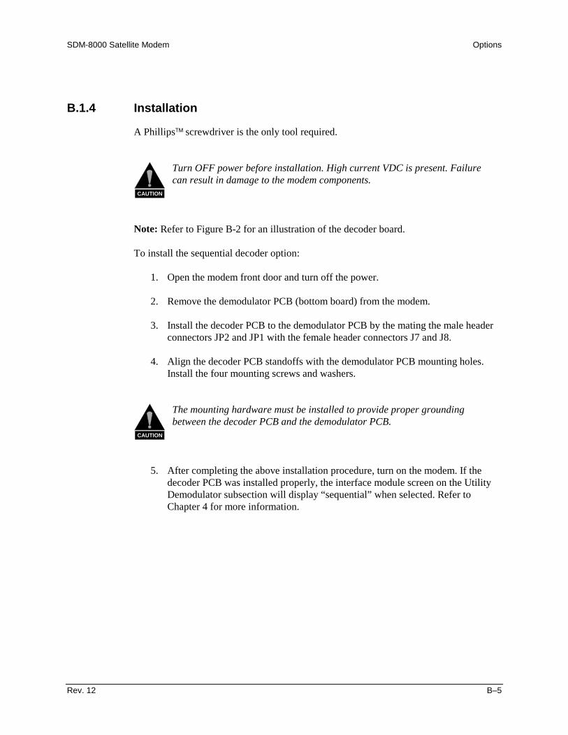
SDM-8000 Satellite Modem Options
Rev. 12 B–5
B.1.4 Installation
A Phillips screwdriver is the only tool required.
CAUTION
Turn OFF power before installation. High current VDC is present. Failurecan result in damage to the modem components.
Note: Refer to Figure B-2 for an illustration of the decoder board.
To install the sequential decoder option:
1. Open the modem front door and turn off the power.
2. Remove the demodulator PCB (bottom board) from the modem.
3. Install the decoder PCB to the demodulator PCB by the mating the male headerconnectors JP2 and JP1 with the female header connectors J7 and J8.
4. Align the decoder PCB standoffs with the demodulator PCB mounting holes.Install the four mounting screws and washers.
CAUTION
The mounting hardware must be installed to provide proper groundingbetween the decoder PCB and the demodulator PCB.
5. After completing the above installation procedure, turn on the modem. If thedecoder PCB was installed properly, the interface module screen on the UtilityDemodulator subsection will display “sequential” when selected. Refer toChapter 4 for more information.

Options SDM-8000 Satellite Modem
B–6 Rev. 12
MODULATOR PCB U35 U27
MOUNTING HARDWARE (4)U39 U26 DEMODULATOR PCBJ7 J8
Figure B-2. Sequential Decoder Installation

SDM-8000 Satellite Modem Options
Rev. 12 B–7
B.2 D&I with Asynchronous Overhead
The D&I with asynchronous overhead PCB (AS/3496-2) is a 5.90” x 6.40” daughter cardthat plugs into the interface PCB. The interface card fits in the middle slot of the modemchassis. The D&I multiplexer works in conjunction with the interface card to enable themodem to transmit or receive fractional parts of a T1 data stream.
The asynchronous overhead data channel is typically used for earth station-to-earthstation communication. The overhead channel is MUXed onto the data and transmitted atan overhead rate of 16/15 of the main channel.
Note: The asynchronous overhead option (AS/3496-1) also works in conjunction withthe interface PCB, but does not include the D&I option. Refer to this section for theoryand installation information. Chapter 1 includes modem compatibility requirements.
B.2.1 Specifications
Refer to Appendix C for specification information.
B.2.2 Asynchronous Overhead Operation
The asynchronous overhead PCB (AS/3496-1) is a 5.90” x 6.40” daughter card that plugsinto the interface PCB.
The asynchronous overhead data channel is typically used for earth station-to-earthstation communication in a closed network application. The overhead channel is MUXedonto the data and transmitted at an overhead rate of 16/15 of the main channel.
The asynchronous overhead option (AS/3496-1) works in conjunction with the interfacePCB but does not include the D&I option.
B.2.3 Theory of Operation
Refer to Figure B-3 for a block diagram of the D&I with asynchronous overhead. Themain sections of the PCB that will be discussed in the theory of operation include:
• Data Interface • ESC• Transmit Multiplexer • Automatic Uplink Power Control• Receive Demultiplexer • Modem-to-Modem Channel for Remote• Asynchronous Overhead • Backward Alarm• Plesiochronous Buffer
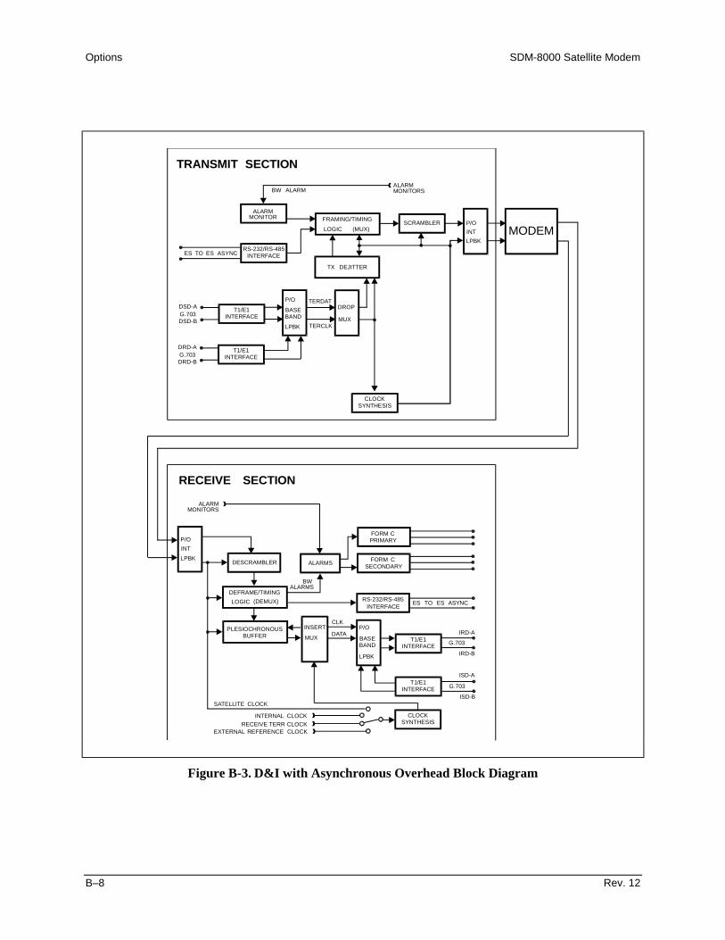
Options SDM-8000 Satellite Modem
B–8 Rev. 12
TRANSMIT SECTION
BW ALARMALARMMONITORS
ALARMMONITORS
RECEIVE SECTION
FORM C
FORM C
PRIMARY
SECONDARYALARMS
MODEMP/O
P/O
P/O
P/O
INT
BASEBAND
BASEBAND
DROP
INSERT
TERDAT
TERCLK
INT
LPBK
LPBK
LPBK
MUX
MUX
LPBK
SCRAMBLER
DESCRAMBLER
PLESIOCHRONOUSBUFFER
FRAMING/TIMING
DEFRAME/TIMING
LOGIC (MUX)
(DEMUX)
INTERFACE
INTERFACE
INTERFACE
INTERFACE
INTERFACE
SYNTHESIS
SYNTHESIS
ALARMMONITOR
ES TO ES ASYNCRS-232/RS-485
T1/E1
T1/E1
T1/E1
T1/E1
CLOCK
CLOCK
TX DEJITTER
LOGIC
ALARMSBW
CLK
INTERFACERS-232/RS-485
G.703
G.703
ES TO ES ASYNC
IRD-A
IRD-B
ISD-A
ISD-B
DATA
G.703
G.703
DSD-A
DRD-A
DSD-B
DRD-B
SATELLITE CLOCK
EXTERNAL REFERENCE CLOCK
INTERNAL CLOCKRECEIVE TERR CLOCK
Figure B-3. D&I with Asynchronous Overhead Block Diagram

SDM-8000 Satellite Modem Options
Rev. 12 B–9
B.2.3.1 Data Interface
The module contains transformer-balanced data interfaces that support CCITT G.703parameters and dejitter. This is compatible with AT&T Digital Speech Interpolation(DSI) service. Data inputs and outputs named are listed below:
Data Inputs Drop send data input A and B (DSD–A and DSD–B)Insert send data input A and B (ISD–A and ISD–B)
Data Outputs Drop receive data output A and B (DRD–A and DRD–B)Insert receive data output A and B (IRD–A and IRD–B)
The system is frequently used with the drop receive data output signal (DRD–A, –B)looped to feed the insert send data input signal (ISD–A, –B). This is done at the far endof any redundancy switching in order to allow transmit and receive chains to be switchedindependently. The zero substitution codes AMI, B8ZS, and HDB3 are user-selectableduring configuration.
A data loopback function on the insert data is available in this section. This enables theuser to determine that the T1 or E1 data parameters correctly match those of thisinterface. The drop data is always hard-wired into loopback.
B.2.3.2 Transmit Multiplexer
The data stream is multiplexed with a 1/15 overhead channel, and the resultantinformation rates are interfaced to the Mod/Demod/Coder sections of the modem. Aphase-locked loop generates the output clock (with overhead), using the input clock as areference. The input clock is normally the recovered clock from the data interface. If avalid input signal is not present, the interface falls back to a 10-5 accuracy referenceclock generated in the modem, and will transmit a valid IESS-308 framing pattern. If thishappens, the link will remain open at the far end and a fault will be signaled.
The transmit data will be replaced with an all 1s pattern (AIS) in the event of certainfailures, in accordance to IESS-308.
As a test mode, the transmit data can be replaced with a 2047 pattern. This selectionoverrides the AIS. Only user data bits are replaced with the pattern, while the ESC,including framing and alarms, will operate normally.
The composite multiplexed data stream is normally fed to the modem for furtherprocessing (scrambling and K=7 Viterbi encoding). The composite data stream may belooped back at this point as a test function, called interface loopback, when the transmitdata rate matches the receive data rate. This allows the customer to test the entireinterface as the ESC is looped to itself through the demultiplexer (DEMUX). Theplesiochronous buffer may also be checked, since user data passes through this circuit.

Options SDM-8000 Satellite Modem
B–10 Rev. 12
B.2.3.3 Receive Demultiplexer
The receive data with overhead is processed in the demultiplexer. This circuit checks andsynchronizes to the frame pattern, and separates the user data from the ESC channel. Ifthe DEMUX is receiving a correct and synchronized signal, it will signal the modem thatthe multiplex system is locked (MUXlock) and passing data. This is indicated byinterrogating the modem, a green LED on the interface, and sending the signal into thereceive fault tree in accordance with IESS-308. Under certain fault conditions defined byIESS-308, the receive user data will be replaced by a pattern with all 1s, and a fault willbe signaled.
B.2.3.4 Asynchronous Overhead
Asynchronous overhead is a 1/15 rate overhead channel that is composed of thefollowing:
• Framing information • Valid data flags• EIA-232 or EIA-485 data • Parity bits• AUPC information (if installed)
The rate of asynchronous data transfers may be selected by the user with the maximumrate available limited to 1.875% of the synchronous data rate. The asynchronousoverhead structure is an Comtech EFData standard and is not compatible with IBS orIDR overhead formats.
B.2.3.5 Plesiochronous Buffer
User data from the DEMUX section is fed into a plesiochronous buffer. The buffer sizeis user selectable in bit increments that correspond to the length of an IESS-308 satellitesuperframe. The increments range from 1 to 32 ms. See the specifications for a list ofvalid entries for each of the selected formats. The buffer automatically centers onresumption of service after an outage or may be commanded to center in the interfaceconfiguration section from the front panel or remotely. The startup buffer will overfillwhen centering to match the satellite frame to the terrestrial frame with a maximum slideof 0.5 ms. In general, manual centering will not be plesiochronous.
The fill status is available as a monitor function and accurate to 1%. Red LEDs on themodule momentarily indicate overflow or underflow incidents. These are stored in thestored fault section of the M&C status registers, along with the date and time of theincident provided by the modem internal clock. These are stored in battery-backed RAM.

SDM-8000 Satellite Modem Options
Rev. 12 B–11
A normal selection is to have the data clocked out of the buffer by the recovered clockfrom the receive data input in order to synchronize the receive data output with thesatellite data. The user may select from two other clock sources as a backup: either a usersupplied external reference clock or the internal clock source.
Problems occurring on either the recovered receive data input clock or the external clock(if selected) will substitute the satellite clock and a fault will be signaled.
B.2.3.6 Engineering Service Channel (ESC)
The ESC uses certain bits of the satellite overhead to implement an EIA-232 datachannel. The two types of available data channels are asynchronous and synchronous.The asynchronous channel works by over sampling input and output EIA-232 data sothat a clock signal is not required. Data rates up to 1/2000 of the satellite rate may beused. Synchronous data channels are also allowed at a rate of 1/512 of the data rate ofthe modem. The synchronous channel requires use of the TX clock provided by themodem for operation.
B.2.3.7 Automatic Uplink Power Control (AUPC)
The AUPC feature is designed for remote communications between a local modem (A)and a remote modem (B). It allows the local modem to maintain a constant (± 0.5 dB)Eb/N0 by requesting changes in transmit power levels from the remote modem. Refer toChapter 4 for complete details of AUPC configuration functions. The user has the abilityto set the following parameters:
• AUPC Enable (turns the AUPC on or off)• Remote Carrier Loss Action (Maximum, Nominal, Hold)• Carrier Loss Action (Maximum, Nominal, Hold)• Set Nominal Power• Set Maximum Power• Set Minimum Power Limit• Set Target Eb/N0
• Set Maximum Tracking Rate
When the AUPC is turned on in the local modem, it can receive commands from theremote interface. The AUPC then increments or decrements the power in 0.5 dB steps,and allows power to be changed for remote or local Carrier Loss. When the AUPC isturned off in the local modem, the commands are still sent, but the local modem will notrespond to the commands.
When Remote AUPC in enabled from the menu of a local modem, that modem becomesthe controller for the distant modem. As the controller for the distant modem, it monitorsit’s own target Eb/N0 and issues appropriate commands to change the distant modem’spower level to meet that target level.
Options SDM-8000 Satellite Modem
B–12 Rev. 12
When Local AUPC is enabled from the menu of a local modem, it is allowing the distantmodem to control the local modem’s TX power level.
If, for example, modem A has Remote AUPC enabled, modem B will automatically haveLocal AUPC enabled. If modem B loses carrier detect, it’s TX power level will matchwhatever setting is selected in the Configuration/Local AUPC/ Local CL Action menu. Ifmodem A loses carrier detect, modem B’s TX power level will match whatever setting isselected in the Configuration/Local AUPC/ Local CL Action menu.
The loss of lock action is as follows (Modem A loses carrier detect):
1. Modem A sets power to Maximum, Nominal, or Hold as specified by CarrierLoss Action.
2. Modem A sends Carrier Loss command to Modem B.
3. Modem B sets power to Maximum, Nominal, or Hold as specified by RemoteCarrier Loss Action.
Note: Local carrier loss has priority over remote carrier loss.
B.2.3.8 Modem to Modem Channel for Remote
This feature allows the user to monitor and control a remote modem location using thefront panel or serial port of the local modem. Refer to Chapter 4 and for complete detailsof AUPC remote configurations. The user can set or reset the following commands:
• Baseband Loopback• TX 2047 Pattern• AUPC Enable
The user can remotely monitor the receive 2047 BER.
B.2.3.9 Backward Alarm
Backward alarm signals are included in the overhead. The signals are sent to the distantside of a satellite link to indicate trouble with the receive side which may be a result ofimproper transmission. The M&C computer monitors the receive side of the link. In theevent of trouble, the M&C sends an alarm over the transmit side to the distant end. Thisalarm signal indirectly includes faults in the downlink chain, since major problems withthe antenna, LNA, or down converter, etc. will cause an interruption in service and faultthe modem. Reception of a backward alarm is indicated as one of the events that causes asecondary alarm. The modem may be interrogated from the front panel or by using theEIA-485 or EIA-232 interface in order to identify the cause of the alarm.

SDM-8000 Satellite Modem Options
Rev. 12 B–13
B.2.4 Unpacking
CAUTION
This equipment contains parts and assemblies sensitive to damage by ESD.Use ESD precautionary procedures when touching, removing, or insertingPCBs.
1. Remove the PCB and mounting hardware from the cardboard caddypack andanti-static material.
2. Check the packing list to ensure the shipment is complete.
3. Inspect the PCB for any shipping damage.
B.2.5 Installation
A Phillips screwdriver is the only tool required.
Use the following information to install the D&I with asynchronous overhead PCB,called the “D&I/asynchronous PCB,” as a daughter card on the interface PCB.
Refer to Figure B-4 for an illustration of the board.
CAUTION
Turn OFF power before installation. High current VDC is present. Failurecan result in damage to the modem components.
To install the D&I asynchronous overhead PCB:
1. Open the modem front door and turn off the power.
2. Remove the interface PCB (middle board) from the modem.
3. Install the D&I/asynchronous PCB to the interface PCB by mating the femaleconnector JP1 on the D&I ribbon cable, with the male connector J6 on theinterface PCB.
4. Align the D&I/asynchronous PCB standoffs with the interface PCB mountingholes. Install the four mounting screws and washers.

Options SDM-8000 Satellite Modem
B–14 Rev. 12
CAUTION
The mounting hardware must be installed to provide proper groundingbetween the D&I/Asynchronous PCB and the interface PCB.
5. After completing the above installation procedure, turn on the modem. If theD&I/asynchronous PCB was installed properly, the interface module screen onthe Utility-Interface subsection will display “OPT:DI” when selected. Refer toChapter 4 for more information.
MOUNTINGHARDWARE (4)
JPI RIBBONCONNECTOR
INTERFAC U111EPCB
DOTTED LINEINDICATES
D&I PCB
Figure B-4. D&I Multiplexer Installation
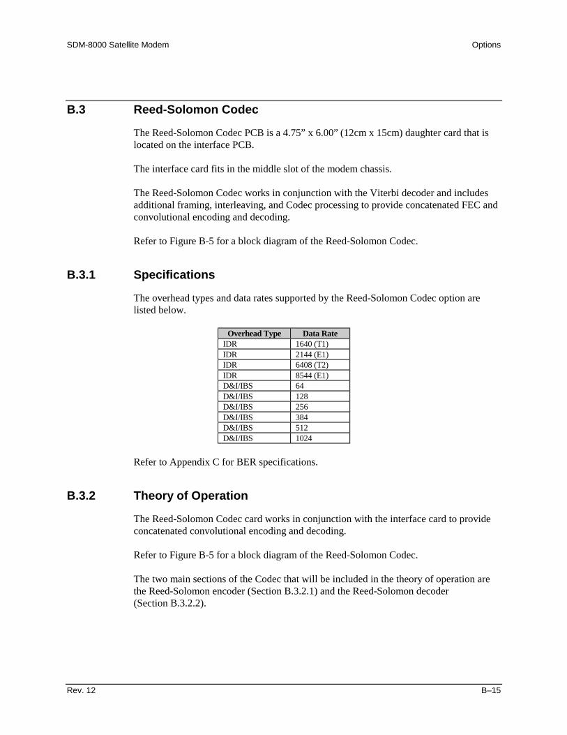
SDM-8000 Satellite Modem Options
Rev. 12 B–15
B.3 Reed-Solomon Codec
The Reed-Solomon Codec PCB is a 4.75” x 6.00” (12cm x 15cm) daughter card that islocated on the interface PCB.
The interface card fits in the middle slot of the modem chassis.
The Reed-Solomon Codec works in conjunction with the Viterbi decoder and includesadditional framing, interleaving, and Codec processing to provide concatenated FEC andconvolutional encoding and decoding.
Refer to Figure B-5 for a block diagram of the Reed-Solomon Codec.
B.3.1 Specifications
The overhead types and data rates supported by the Reed-Solomon Codec option arelisted below.
Overhead Type Data RateIDR 1640 (T1)IDR 2144 (E1)IDR 6408 (T2)IDR 8544 (E1)D&I/IBS 64D&I/IBS 128D&I/IBS 256D&I/IBS 384D&I/IBS 512D&I/IBS 1024
Refer to Appendix C for BER specifications.
B.3.2 Theory of Operation
The Reed-Solomon Codec card works in conjunction with the interface card to provideconcatenated convolutional encoding and decoding.
Refer to Figure B-5 for a block diagram of the Reed-Solomon Codec.
The two main sections of the Codec that will be included in the theory of operation arethe Reed-Solomon encoder (Section B.3.2.1) and the Reed-Solomon decoder(Section B.3.2.2).

Options SDM-8000 Satellite Modem
B–16 Rev. 12
CHASSISINTERFACE
CDRDATALOOPBACK
TX DATA
TX CLK
MUXDATA
MUX CLK
INTERFACEPCB
MUX CDR CLK
DECDATA
OVERHEAD
PROCESSOR
RXDATALOOPBACK
MUX
DMXDATA
DMX CLKRX CLK
DEC CLK
REED-SOLOMON
Figure B-5. Reed-Solomon Codec Block Diagram
B.3.2.1 Reed-Solomon Encoder
A block diagram of the Reed-Solomon encoder section is shown in Figure B-6.
The Reed-Solomon encoder section includes the following circuits:
• Synchronous Scrambler • Serial/Parallel Converter• Reed-Solomon Codec • Parallel/Serial Converter• Synchronous First In/First Out • Interleaver
TXSATDATJP2
PARALLELRAMUNIQUE WORDRSSERIAL
SYNCHRONOUSSYNCHRONOUSMUXDATA(SERIAL)
JP2
MUXCLKJP2 SCRAMBLER
U3CONVERTER
PARALLELTO
U3 U6FIFO
CODEC(ENCODER SECTION) INSERTION
U2
INTERLEAVER
U3 U4
INTERLEAVER TO SERIAL
U3 TXSATCLKJP2
ADDRESSGENERATOR
U3
RS TIMING CONTROLLER
U3
Figure B-6. Reed-Solomon Encoder Section Block Diagram

SDM-8000 Satellite Modem Options
Rev. 12 B–17
The data and clock signals (MUXDATA and MUXCLK) come from the multiplexer onthe interface PCB, and are sent to the Reed-Solomon encoder section through connectorJP2. Since the data input to the Reed-Solomon encoder is serial, the data passes througha self-synchronizing serial scrambler, in accordance with specification INTELSAT-308,Rev. 6B.
The host software allows the scrambler to be turned on or off at the front panel asrequired by the user. If the scrambler is disabled, the data passes through the scramblerunaltered.
The data then passes through a serial/parallel converter, which changes the data to an 8-bit word. The word then passes to a synchronous First In/First Out (FIFO) buffer,because the rate is different than the encoded data rate. Once buffered by the FIFO, thedata passes to the Reed-Solomon Codec.
Refer to Figure B-7 for the Reed-Solomon code page format. The Reed-Solomon outerCodec reads the data in blocks of n bytes, and calculates and appends check bytes to theend data block. The letter k represents the total number of bytes in a given block of dataout of the Codec. The letter n represents the number of data bytes in a given block.
The term, k - n = 2t, is the total number of check bytes appended to the end of the data.This is referred to as the “Reed-Solomon overhead.” The terms k, n, and t will vary,depending on the data rate used. The output data is passed to a block interleaver.
Since errors from the Viterbi decoder usually occur in bursts, a block interleaver with adepth of 4 is used in accordance with the INTELSAT-308 Rev. 6B specification. Theinterleaver has the effect of spreading out the errors across blocks of data, instead ofconcentrating the errors in a single block of data. Since there are fewer errors in anygiven block, there is a greater chance that the Reed-Solomon decoder can correct theerrors on the receiving end of the satellite link. To allow the decoder to synchronize tothe data, four unique words are inserted in the last two bytes of the last two pages at theend of each page of data (Figure B-7).
Once the data passes through the interleaver, it is fed through a parallel/serial converterand sent back to the interface PCB. After further processing by the interface PCB, thedata is sent to the modulator PCB.
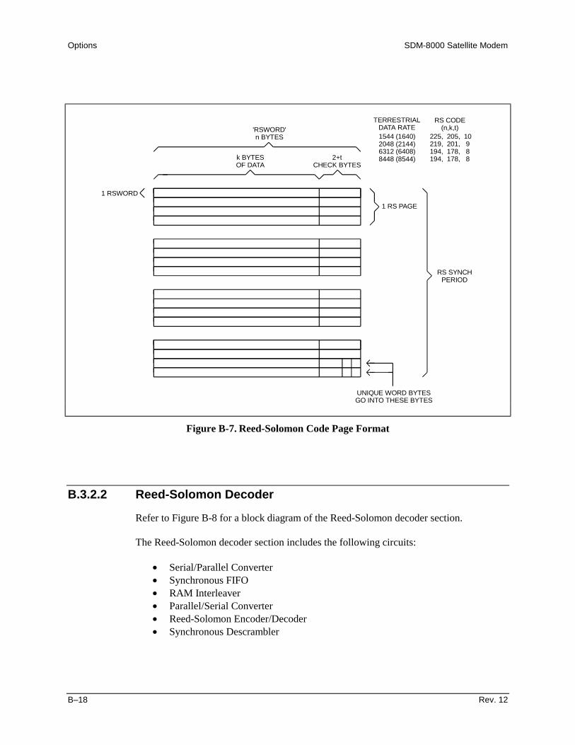
Options SDM-8000 Satellite Modem
B–18 Rev. 12
k BYTESOF DATA
'RSWORD'n BYTES
1 RSWORD
1 RS PAGE
RS SYNCHPERIOD
UNIQUE WORD BYTESGO INTO THESE BYTES
2+tCHECK BYTES
TERRESTRIALDATA RATE
RS CODE(n,k,t)
1544 (1640)2048 (2144)6312 (6408)8448 (8544)
225, 205, 10219, 201, 9194, 178, 8194, 178, 8
Figure B-7. Reed-Solomon Code Page Format
B.3.2.2 Reed-Solomon Decoder
Refer to Figure B-8 for a block diagram of the Reed-Solomon decoder section.
The Reed-Solomon decoder section includes the following circuits:
• Serial/Parallel Converter• Synchronous FIFO• RAM Interleaver• Parallel/Serial Converter• Reed-Solomon Encoder/Decoder• Synchronous Descrambler
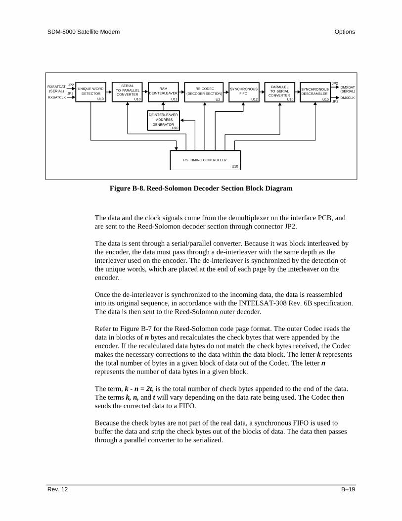
SDM-8000 Satellite Modem Options
Rev. 12 B–19
DMXDAT(SERIAL)
JP2PARALLELSYNCHRONOUS SYNCHRONOUSRS
SERIALRAMUNIQUE WORDRXSATDAT
(SERIAL)
JP2
RXSATCLKJP2 DETECTOR
U10CONVERTER
PARALLELTO
U10 U11
DEINTERLEAVERCODEC
(DECODER SECTION)
U2
DEINTERLEAVER
U12 U10
FIFO DESCRAMBLERTO SERIAL
U10 DMXCLKJP2
ADDRESSGENERATOR
U10
RS TIMING CONTROLLER
U10
Figure B-8. Reed-Solomon Decoder Section Block Diagram
The data and the clock signals come from the demultiplexer on the interface PCB, andare sent to the Reed-Solomon decoder section through connector JP2.
The data is sent through a serial/parallel converter. Because it was block interleaved bythe encoder, the data must pass through a de-interleaver with the same depth as theinterleaver used on the encoder. The de-interleaver is synchronized by the detection ofthe unique words, which are placed at the end of each page by the interleaver on theencoder.
Once the de-interleaver is synchronized to the incoming data, the data is reassembledinto its original sequence, in accordance with the INTELSAT-308 Rev. 6B specification.The data is then sent to the Reed-Solomon outer decoder.
Refer to Figure B-7 for the Reed-Solomon code page format. The outer Codec reads thedata in blocks of n bytes and recalculates the check bytes that were appended by theencoder. If the recalculated data bytes do not match the check bytes received, the Codecmakes the necessary corrections to the data within the data block. The letter k representsthe total number of bytes in a given block of data out of the Codec. The letter nrepresents the number of data bytes in a given block.
The term, k - n = 2t, is the total number of check bytes appended to the end of the data.The terms k, n, and t will vary depending on the data rate being used. The Codec thensends the corrected data to a FIFO.
Because the check bytes are not part of the real data, a synchronous FIFO is used tobuffer the data and strip the check bytes out of the blocks of data. The data then passesthrough a parallel converter to be serialized.

Options SDM-8000 Satellite Modem
B–20 Rev. 12
The data is sent through a self-synchronizing serial descrambler in accordance with theINTELSAT-308 Rev. 6B specification. The descrambler converts the data back into theoriginal data that the user intended to send. The synchronous descrambler issynchronized by the detection of the unique word at the end of each Reed-Solomon page.The data is then sent to the interface PCB for further processing.
B.3.3 Unpacking
CAUTION
This equipment contains parts and assemblies sensitive to damage by ESD.Use ESD precautionary procedures when touching, removing, or insertingPCBs.
1. Remove the Reed-Solomon PCB and mounting hardware from the cardboardcaddypack and anti-static material.
2. Check the packing list to ensure the shipment is complete.
3. Inspect the Reed-Solomon PCB for any shipping damage.
B.3.4 Installation
A Phillips screwdriver is the only tool required.
Refer to Figure B-9 for an illustration of the board.
CAUTION
Turn OFF power before installation. High current VDC is present. Failurecan result in damage to the modem components.
To install the Reed-Solomon Codec PCB:
1. Open the modem front door and turn off the power.
2. Remove the interface PCB (middle board) from the modem.
3. Install the Reed-Solomon PCB to interface PCB by mating the male headerconnectors JP1 and JP2 with the female header connectors J3 and J4.
4. Align the Reed-Solomon PCB standoffs with the interface PCB mounting holes.Install the four mounting screws and washers.

SDM-8000 Satellite Modem Options
Rev. 12 B–21
CAUTION
The mounting hardware must be installed to provide proper groundingbetween the Reed-Solomon PCB and the interface PCB.
5. After completing the above installation procedure, turn on the modem. If theReed-Solomon PCB was installed properly, the interface module screen on theUtility Interface subsection will display “OPT:Reed-Solomon” or “OPT:DI,Reed-Solomon” (if the D&I is also installed). Refer to Chapter 4 for moreinformation.
J4 (INTF. PCB)JP2 (R-S PCB)
DASHED LINEINDICATES
REED-SOLOMONPCB INSTALLED
MOUNTINGHARDWARE(4 PLACES)
INTERFACE PCB(AS/3495)
J3 (INTF. PCB)JP1 (R-S PCB)
Figure B-9. Reed-Solomon Codec Installation

Options SDM-8000 Satellite Modem
B–22 Rev. 12
B.4 Interface Relay Board
The interface relay board is a 3.50” x 6.50” (9cm x 17cm) daughter card (Figure B-10)that is located on the interface PCB. This option provides the modem user with an easymethod to change the data interface. The interface relay replaces the need to physicallychange the interface multi-pin jumpers.
The user can select the following data interfaces from the modem front panel:
Data Interface Modem Circuitry AffectedMIL-STD-188 Receiver, driver, and handshake signalsV.35 Receiver, driver, and handshake signalsG.703 Receiver and driver
Figure B-10. Interface Relay Board
B.4.1 Theory of Operation
The interface relay board works in conjunction with the host firmware on thedisplay/M&C PCB and the M&C firmware on the interface PCB. The option providesfront panel selection for the MIL-STD-188, V.35, and G.703 data interfaceconfigurations by using Type 2 FORM C and Type 4 FORM C relays.

SDM-8000 Satellite Modem Options
Rev. 12 B–23
B.4.2 Unpacking
CAUTION
This equipment contains parts and assemblies sensitive to damage by ESD.Use ESD precautionary procedures when touching, removing, or insertingPCBs.
1. Remove the interface relay board and firmware from the cardboard caddypackand anti-static material.
2. Check the packing list to ensure the shipment is complete.
3. Inspect the interface relay board for any shipping damage.
B.4.3 Installation
An IC tool is required.
Use the following procedure to install the interface relay board as a daughter card on theinterface PCB. The two firmware ICs are installed on the interface PCB and thedisplay/M&C PCB.
Refer to Figure B-11 for illustrations of the interface PCB, display/M&C PCB, andjumper and firmware locations.
CAUTION
Turn OFF the power before installation. High Current VDC is present.Failure can result in damage to the modem components.
To install the interface relay board:
1. Open the modem front door and turn off the power.
2. Remove the interface PCB (middle board) from the modem.
3. Remove the following jumpers from the interface PCB:
JP1 JP9JP2 JP10JP3 JP11JP5 JP22JP7 JP23

Options SDM-8000 Satellite Modem
B–24 Rev. 12
4. Change JP16 on the interface PCB to the 64K position.
5. Install the interface relay board by carefully mating the male and female headerconnectors listed in Step 3 (also include J5). Note that both sets of connectorshave the same connector number.
CAUTION
Ensure the connectors are properly aligned to prevent pin damage.
When the connectors are properly aligned, carefully install the daughter cardfully on the interface card.
6. After completing the above installation procedure, turn on the modem. Refer toSection B.4.4.1 for an operational check.
7. Re-install the interface PCB to the modem.
8. Remove the EEPROM marked FW/2448 from U17 on the display/M&C PCB(located on the front panel). Install the Host M&C firmware marked 2448-1N (ornewer).
9. After completing the above procedures, turn on the modem and refer toSection B.4.4.1 for an operational check.
B.4.4 Operation
This section includes an operational check and the Front Panel menu for the interfacerelay option. If required, refer to Chapter 4 for more information.
B.4.4.1 Operational Check
Use the following procedure to check the interface relay board option:
1. Enter the Function Select Utility and Utility Interface menus.
2. Select “Relay” at the Interface Option menu. If the interface relay option wasinstalled properly, the modem display should show a “+” at the right side of thewindow.
Note: A “+” is shown on the display for each installed option.
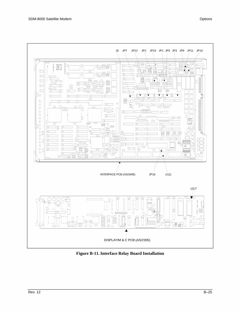
SDM-8000 Satellite Modem Options
Rev. 12 B–25
J5 JP7 JP22 JP2 JP23 JP1 JP5 JP3 JP9 JP11 JP10
INTERFACE PCB (AS/3495) JP16 U111
U17
DISPLAY/M & C PCB (AS/2305)
Figure B-11. Interface Relay Board Installation

Options SDM-8000 Satellite Modem
B–26 Rev. 12
B.4.4.2 Interface Option Menu
This menu enables the user to select the following options:
• D&I• Reed-Solomon• ASYNC overhead• AUPC• Relay (Interface Relay Board)
Note: A “+” is shown on the display window for each installed option.
B.4.4.3 Interface Build Menu
This menu displays the type of modem operation (Types 1 through 4).
B.4.4.4 G.703 Menu
The G.703 Level Type menu has the following options for selecting data rates and pulseshapes. Refer to Chapter 6 for diagrams of a typical output spectrum.
Configuration DescriptionHIGH DRIVE Rectangular pulse. 8448 Mbit/s.LOW SHAPED Rectangular pulse. 6312 kbit/s.LOW LEVEL A non-standard pulse option for a lower amplitude than the nominal level
option.NOMINAL SHAPED A non-standard pulse option for a higher amplitude than the low shaped
option. This is pulse shaped due to line loss problems.NOMINAL LEVEL(DEFAULT)
Rectangular pulse. 1544 kbit/s and 2048 kbit/s.

SDM-8000 Satellite Modem Options
Rev. 12 B–27
B.5 Digital Video Broadcast (DVB)
The DVB mode of the SDM-8000 sets the Viterbi ForwardError Correction (FEC). Reed-Solomon and framing to becompatible with the European Telecommunications StandardETS 300 421 (DVB)
The DVB mode will support data rates up to 8.448 Mbit/s.
The DVB mode employs the following features:
• Special framing• Scrambling• Reed-Solomon coding• Code rate puncturing
Applicable specifications include:
• European Telecommunications Standard ETS 300 421• ISO/IEC 13818-1
Figure B-12 shows the conceptual block diagrams for the transmit and receive processesof the SDM-8000 when configured for DVB operation.
I
Q
DATA
CLOCK
DATA
CLOCKQ
I
BASEBANDPHYSICAL
INTERFACE
SYNCDECODER(Correlator)
DE-JITTERFIFO
2047 and AISGENERATORS
SYNC 1INVERSION
andSCRAMBLER
REED-SOLOMON
CODER(Outer Coder)
DEPTH 12INTERLEAVER
K = 7CONVOLUT.ENCODER
PUNCTURINGand
MAPPING(Inner Coder)
NYQUISTFILTERS
(35% SRC)
TO QPSKMODULATOR
A) TRANSMIT PROCESS
FROM QPSKDEMODULATOR
NYQUISTFILTERS
(35% SRC)
MAPPINGand
DEPUNCTUR.
VITERBIDECODER
(Inner Decoder)
SYNCDECODER(Correlator)
DEPTH 12DEINTERLEAV.
REED-SOLOMONDECODER
(Outer Decoder)
DESCRAMBLEand
SYNC 1INVERSION
DOPPLERBUFFER
BASEBANDPHYSICAL
INTERFACE
2047 andAIS DETECT
B) RECEIVE PROCESS
Figure B-12. Block Diagram of SDM-8000 Configured for DVB Operation

Options SDM-8000 Satellite Modem
B–28 Rev. 12
Note: The Intermediate Frequency (IF) physical interfaces and Quadrature Phase ShiftKeying (QPSK) modulator are functionally equivalent to those used during INTELSAToperation, and will not be described here.
The blocks shown in Figure B-12 have special functionality when operating in DVBmode. Each block is described in the following sections.
B.5.1 Option Requirements
This section covers the module types that are compatible with each option, and theminimum software requirements for the modem PCBs. The following options list theinterface type and PCB assembly numbers.
B.5.1.1 DVB Option
The DVB option works in conjunction with the Viterbi decoder, and includes additionalframing, interleaving, and Codec processing to provide:
• Concatenated FEC• Convolutional encoding/decoding
This option can be factory or user installed.
Refer to Table B-2 for minimum modem compatibility requirements.
Table B-2. Modem Compatibility RequirementsAssembly Assembly # Firmware
Interface PCB AS/3495-5 FW/6218-B U109, U110FW/2451-2P U111
Display/M&C PCB AS/2305 Rev. C6 FW/2448-1P U17Modulator PCB AS/3415 FW.2449-1J U27
FW/2621-L U35Demodulator PCB AS/3416 FW/2450-2G U26
FW/3461-L U39DVB Reed-Solomon PCB AS/4980-3 Rev. A FW/5134-1 U19

SDM-8000 Satellite Modem Options
Rev. 12 B–29
B.5.1.2 Display/M&C
See Figure B-13.
The SDM-8000 modem with the DVB option has two additions to the front panelselections. These additions are the selection of the transmit and receive framingconfiguration. The terrestrial framing selections of 188 Framing, 204 Framing, or NoFraming can each be found in the Configuration Interface menu.
Figure B-13. Configuration Interface Menu
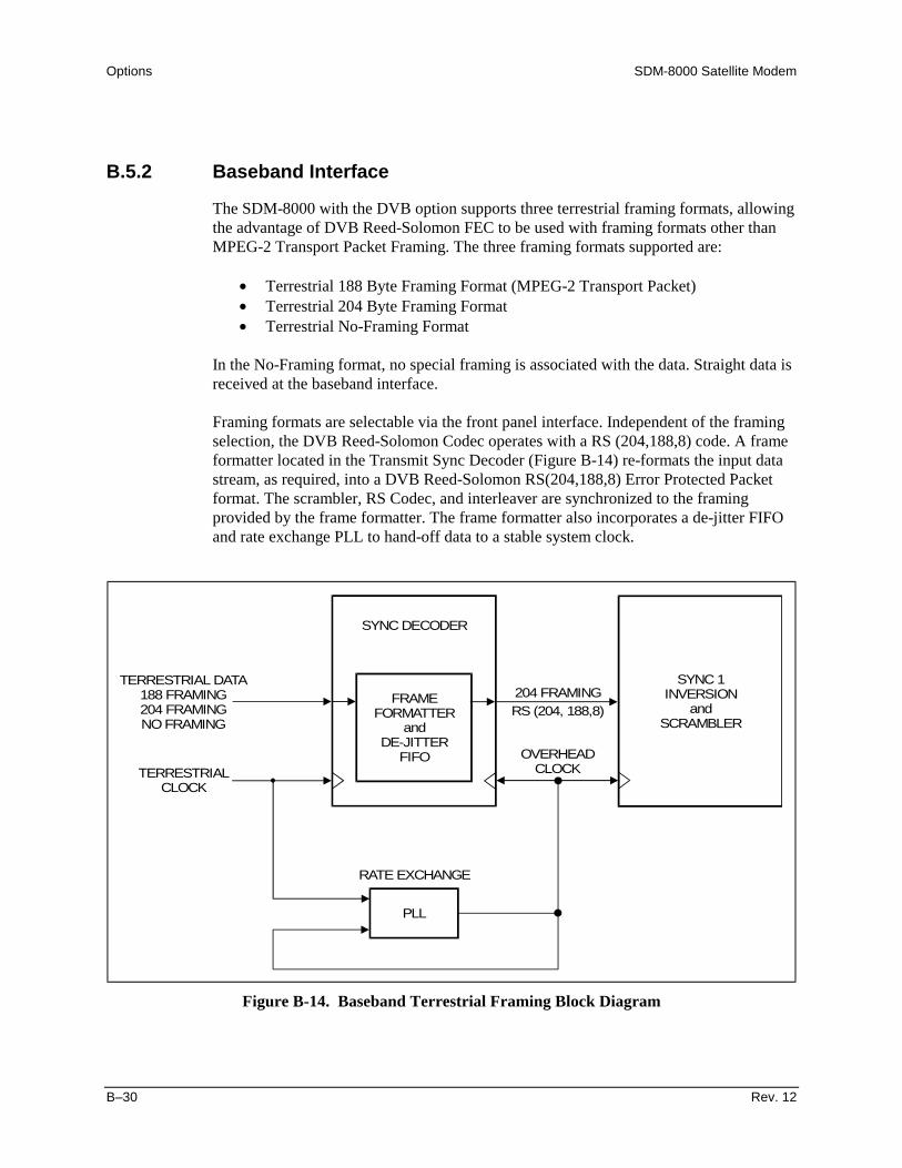
Options SDM-8000 Satellite Modem
B–30 Rev. 12
B.5.2 Baseband Interface
The SDM-8000 with the DVB option supports three terrestrial framing formats, allowingthe advantage of DVB Reed-Solomon FEC to be used with framing formats other thanMPEG-2 Transport Packet Framing. The three framing formats supported are:
• Terrestrial 188 Byte Framing Format (MPEG-2 Transport Packet)• Terrestrial 204 Byte Framing Format• Terrestrial No-Framing Format
In the No-Framing format, no special framing is associated with the data. Straight data isreceived at the baseband interface.
Framing formats are selectable via the front panel interface. Independent of the framingselection, the DVB Reed-Solomon Codec operates with a RS (204,188,8) code. A frameformatter located in the Transmit Sync Decoder (Figure B-14) re-formats the input datastream, as required, into a DVB Reed-Solomon RS(204,188,8) Error Protected Packetformat. The scrambler, RS Codec, and interleaver are synchronized to the framingprovided by the frame formatter. The frame formatter also incorporates a de-jitter FIFOand rate exchange PLL to hand-off data to a stable system clock.
FRAMEFORMATTER
andDE-JITTER
FIFO
SYNC DECODER
SYNC 1INVERSION
andSCRAMBLER
PLL
204 FRAMINGRS (204, 188,8)
RATE EXCHANGE
OVERHEADCLOCK
TERRESTRIAL DATA188 FRAMING204 FRAMINGNO FRAMING
TERRESTRIALCLOCK
Figure B-14. Baseband Terrestrial Framing Block Diagram

SDM-8000 Satellite Modem Options
Rev. 12 B–31
B.5.2.1 Terrestrial 188 Byte Frame Format (MPEG-2 Transport DataPacket)
B.5.2.1.1 Transmit Terrestrial 188 Byte Frame Format
In DVB 188 byte frame format mode, the transmit baseband interface accepts 188-byteMPEG-2 transport packets in bit serial format. Figure B-15 shows the packetarrangement.
SYNCBYTE PAYLOAD (187 BYTES)
188 BYTES(1,504 BITS)
Figure B-15. MPEG-2 Transport Packet
The frame formatter re-formats the packet into a 204 byte RS error protected format,de-jitters the data, then passes it to the Sync 1 inversion and scrambler block.
B.5.2.1.2 Receive Terrestrial 188 Byte Frame Format
Refer to Figure B-15.
The receive DVB baseband interface takes data from the Sync decoder logic andprovides bit serial data to the outside world in 188-byte packets (1,504 bits).
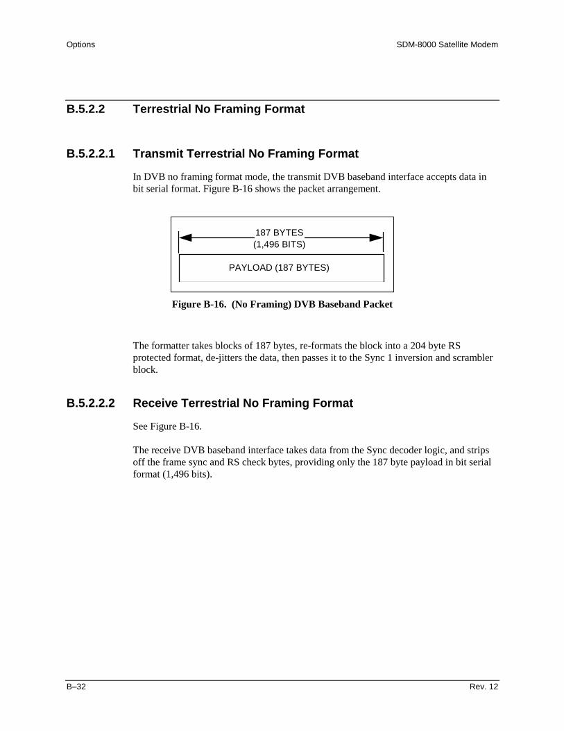
Options SDM-8000 Satellite Modem
B–32 Rev. 12
B.5.2.2 Terrestrial No Framing Format
B.5.2.2.1 Transmit Terrestrial No Framing Format
In DVB no framing format mode, the transmit DVB baseband interface accepts data inbit serial format. Figure B-16 shows the packet arrangement.
PAYLOAD (187 BYTES)
187 BYTES(1,496 BITS)
Figure B-16. (No Framing) DVB Baseband Packet
The formatter takes blocks of 187 bytes, re-formats the block into a 204 byte RSprotected format, de-jitters the data, then passes it to the Sync 1 inversion and scramblerblock.
B.5.2.2.2 Receive Terrestrial No Framing Format
See Figure B-16.
The receive DVB baseband interface takes data from the Sync decoder logic, and stripsoff the frame sync and RS check bytes, providing only the 187 byte payload in bit serialformat (1,496 bits).

SDM-8000 Satellite Modem Options
Rev. 12 B–33
B.5.2.3 Terrestrial 204 Byte Framing Format
B.5.2.3.1 Transmit Terrestrial 204 Byte Framing Format
In the DVB 204 byte frame format mode the transmit baseband interface accepts data in204-byte packets in bit serial format that are composed of 188-byte MPEG-2 packets. Inaddition, 16 null bytes are included as place holders for Reed-Solomon overhead.Figure B-17 shows the packet arrangement.
204 BYTES(1,632 BITS)
SYNCBYTE PAYLOAD (187 BYTES) ZERO PADDING
16 BYTES
Figure B-17. 204-byte Mode Baseband Packet
The data is de-jittered and passed to the Sync 1 inversion and scrambler block.
B.5.2.3.2 Receive Terrestrial 204 Byte Framing Format
See Figure B-17.
The receive 204 byte baseband interface takes data from the Sync decoder logic, andprovides bit serial data in 204 byte packets (1,632 bits) to the outside world.

Options SDM-8000 Satellite Modem
B–34 Rev. 12
B.5.3 Sync Decoder (Correlator)
See Figure B-13.
Through the front panel interface, a framing selection is chosen to match that of theterrestrial data framing.
Sync Decoder circuitry will attempt to “lock” to the framing structure selected throughthe front panel. Once the Sync Decoder is “locked” and the framing structure is known tothe Sync Decoder, the data packet is said to be correlated. The resulting frame structureis now in a known relationship to the scrambler, the Reed-Solomon Codec, and theinterleaver.
B.5.3.1 Transmit/Receive Contingencies
In the case when the Sync Decode logic cannot lock to the framing pattern selected onthe front panel, an internal Alarm Indication Signal (AIS) generator fills the payloaddata with all 1s. Frame sync bytes are inserted into the data stream according to theframing selected on the front panel. Every eighth frame sync byte shall be inverted fordescrambler synchronization.
Note: In No Framing mode, the input data stream will always be framed and transmitted.
B.5.3.2 Transport Error Indicator
The transport error indicator is a one bit flag. When set to “1”, it indicates that at leastone uncorrectable bit error exists in the associated transport packet. This bit is the firstbit of the first byte following the frame sync byte. Refer to ISO/IEC DIS 13818-1Section 2.4.3.3.
Note: In No Framing mode, the transport error indicator bit flag is not implemented.

SDM-8000 Satellite Modem Options
Rev. 12 B–35
B.5.4 Sync 1 Inversion and Scrambler/Descrambler
In compliance with the DVB specifications, and to ensure adequate binary transitions,the payload data (187-bytes) in the transport packet is scrambled using a Pseudo RandomBinary Sequence (PRBS) generator. The polynomial used for the PRBS is:
The basic scrambler/descrambler is shown in Figure B-18.
1 2 3 4 5 6 7 8 9 10 11 12 13 14 15
INITIALIZATION SEQUENCE
PRBS GENERATOR
ENABLE FROMSYNC DETECT LOGIC
CLEAR/SCRAMBLEDDATA IN
SCRAMBLED/DESCRAMBLED
DATA OUT
1 0 0 1 0 1 0 1 0 0 0 0 0 0 0
Figure B-18. Scrambler/Descrambler
At every eighth transport packet, the sequence “100101010000000” is loaded into thePRBS registers. The inverted sync byte is used to initialize the PRBS generator.
1 + X14 + X15

Options SDM-8000 Satellite Modem
B–36 Rev. 12
B.5.4.1 DVB (De)Scrambler
The DVB specifications require that the inverted sync byte detection be used to load thePRBS generator every eight sync bytes, and that the PRBS generator run continuouslyuntil the next load (eight packet period).
The first bit at the output of the PRBS generator is applied to the first bit of the first bytefollowing the inverted MPEG-2 sync byte (i.e., 0xB8). To aid other synchronizationfunctions during the MPEG-2 sync bytes of the subsequent seven transport packets, thePRBS generation continues, but its output is gated off, leaving these bytes unscrambled.
There is an additional 16 bytes of padding at the end of each transport packet. Thepadding is reserved for Reed-Solomon (RS) overhead. (To be compatible with the DVBspecification, the PRBS generator must be halted and the scrambler disabled during these16 padding bytes.) The period of the PRBS generator for DVB mode is:
PERIOD 8 PACKETS 1 INVERTED SYNC BYTE 1503 BYTES= ∗ − − =204 BYTES
PACKET16 PAD BYTES
PACKET
Figure B-19 shows the relationship.
Note: The scrambler and the descrambler work in the same way, except that scrambleddata is input and descrambled data is output.
Figure B-19. DVB Scrambler Sequence
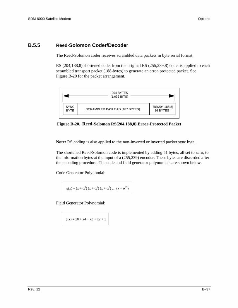
SDM-8000 Satellite Modem Options
Rev. 12 B–37
B.5.5 Reed-Solomon Coder/Decoder
The Reed-Solomon coder receives scrambled data packets in byte serial format.
RS (204,188,8) shortened code, from the original RS (255,239,8) code, is applied to eachscrambled transport packet (188-bytes) to generate an error-protected packet. SeeFigure B-20 for the packet arrangement.
SYNCBYTE SCRAMBLED PAYLOAD (187 BYTES)
204 BYTES(1,632 BITS)
RS(204,188,8)16 BYTES
Figure B-20. Reed-Solomon RS(204,188,8) Error-Protected Packet
Note: RS coding is also applied to the non-inverted or inverted packet sync byte.
The shortened Reed-Solomon code is implemented by adding 51 bytes, all set to zero, tothe information bytes at the input of a (255,239) encoder. These bytes are discarded afterthe encoding procedure. The code and field generator polynomials are shown below.
Code Generator Polynomial:
Field Generator Polynomial:
g(x) = (x + α0) (x + α1) (x + α2) … (x + α15)
p(x) = x8 + x4 + x3 + x2 + 1

Options SDM-8000 Satellite Modem
B–38 Rev. 12
B.5.6 Depth 12 Interleaver/De-interleaver
Conceptually, the interleaver is composed of I = 12 branches, cyclically connected to theinput byte stream by the input switch. Each branch is a FIFO shift register, with depth =17 x branch index. The cells of the FIFO contain 1 byte, and the input and outputbranches are synchronized. For synchronization purposes, the sync bytes and invertedsync bytes are always routed in branch 0 of the interleaver, corresponding to a null delay.
The de-interleaver is similar in principle to the interleaver, but the branch indexes arereversed (i.e., branch 0 corresponds to the longest delay). De-interleaver synchronizationis accomplished by routing the first recognized sync byte to branch 0.
Figure B-21 shows the interleaver/de-interleaver block diagram.
17
17x2
17x3
17x11
0
1
2
3
11
0
1
2
3
11
17x110 0
17x38 8
17x29 9
1710 10
11 11
•••
•••
INTERLEAVER
SYNC BYTE ROUTE
DE-INTERLEAVER
17 BYTE FIFO SHIFT REGISTER
SYNC BYTE ROUTE
Figure B-21. Interleaver/De-interleaver
An interleaved frame is generated by applying convolutional interleaving (with depthI = 12) to the error-corrected packets.

SDM-8000 Satellite Modem Options
Rev. 12 B–39
Figure B-22 shows the interleaved frame structure.
SYNC 1or
SYNC n203 BYTES 203 BYTES
INTERLEAVING DEPTH I = 12
SYNC 1or
SYNC n
Figure B-22. Interleaved Frame Structure
The interleaved frame is composed of overlapping error-protected packets delimited byinverted or non-inverted MPEG-2 sync bytes, preserving the periodicity of 204-bytes.

Options SDM-8000 Satellite Modem
B–40 Rev. 12
B.5.7 Inner Coder/Decoder
The transmit convolutional coder is a standard k = 7, rate 1/2 (G1 = 171, G2 = 133),followed by a programmable puncturing unit. The code rates supported are 1/2, 3/4,and 7/8.
B.5.7.1 Punctured Operation
The DVB puncturing scheme differs from that specified by IESS-308 (INTELSAT), andis shown in Figure B-23.
G1(1) G1(2) G1(3)
G2(1) G2(2) G2(3)
G1(1)
G2(1)
G2(2)
G1(3)
RATE 1/2CONVOLUTIONALENCODED DATA
RATE 3/4 ENCODEDPUNCTURED CHANNELDATA
G1(1) G1(2) G1(3)
G2(1) G2(2) G2(3)
G1(1)
G2(1)
G2(2)
G2(3)
RATE 7/8 ENCODEDPUNCTURED CHANNELDATA
G1(4) G1(5) G1(6)
G2(4) G2(5) G2(6)
G1(7)
G2(7)
G2(4)
G1(5)
G2(6)
G1(7)
B) RATE 7/8 PUNCTURE PATTERN
A) RATE 3/4 PUNCTURE PATTERN
= PUNCTURED SYMBOL (DELETED)
X
Y
I
Q
X
Y
I
Q
RATE1/2CONVOLUTIONALENCODED DATA
Figure B-23. DVB Puncturing

SDM-8000 Satellite Modem Options
Rev. 12 B–41
In punctured operation (rates 3/4 and 7/8), a rate exchange is required between the rate1/2 convolutional encoded data and the encoded punctured channel data.
Note: The DVB specification also describes rate 2/3 and rate 5/6 puncturing, but theSDM-8000 does not support these code rates at this time.
Table B-3 shows the ratios between the convolutional encoder’s clock and the symbolclock for each exchange rate.
Table B-3. Rate Exchange Ratios for DVB PuncturingRate Ratio Comment7/8 7:43/4 3:21/2 1:1 No symbols are punctured, therefore no rate
exchange is required.
The reception process works by shuffling the encoded punctured channel data to theappropriate positions for the rate 1/2 Viterbi decoder. Null symbol indicators are insertedinto the punctured symbol positions in the rate 1/2 data stream.
Again, for rates 3/4 and 7/8, a rate exchange is required for the symbol clock to Viterbiclock hand-off. For rate 1/2, no symbols are punctured, and therefore, no rate exchangeis required.
B.5.7.2 Signal Space Mapping
DVB operation employs conventional Gray-coded QPSK modulation with absolutemapping (no differential coding). Bit mapping in the signal space is shown in FigureB-24.
Q
I
I = 0Q = 0
I = 0Q = 1
I = 1Q = 1
I = 1Q = 0
Figure B-24. QPSK Constellation

Options SDM-8000 Satellite Modem
B–42 Rev. 12
B.5.8 Nyquist Filters
Prior to modulation, the I and Q baseband signals are passed through Nyquist filtersexhibiting a square-root, raised-cosine transfer function with a 35% rolloff factor. Thetheoretical transfer function is defined by the following expression:
where:
The reception process uses Nyquist filters exhibiting the same transfer function as thetransmission process (matched filters). The receiving Nyquist filters are incorporateddirectly after the QPSK demodulator. The I and Q outputs of these filters are digitizedand mapped to 3-bit, soft-decision symbols for subsequent de-puncturing (if required)and Viterbi decoding.
H f f f N( ) ( )= −1 1for | |< α
( ) ( )H ff
f f f f fN
NN N N( ) sin | | | |= + −
− ≤ ≤ +12
12 2
1 1πα
α αfor
H f f f N( ) ( )= +0 1for | |> α
α =.35
fT
RN
S
S= =12 2
is the Nyquist frequency
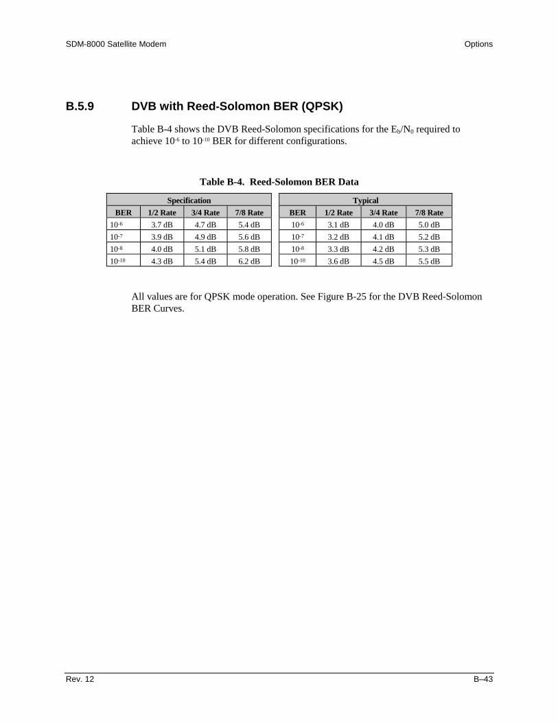
SDM-8000 Satellite Modem Options
Rev. 12 B–43
B.5.9 DVB with Reed-Solomon BER (QPSK)
Table B-4 shows the DVB Reed-Solomon specifications for the Eb/N0 required toachieve 10-6 to 10-10 BER for different configurations.
Table B-4. Reed-Solomon BER Data
Specification TypicalBER 1/2 Rate 3/4 Rate 7/8 Rate BER 1/2 Rate 3/4 Rate 7/8 Rate
10-6 3.7 dB 4.7 dB 5.4 dB 10-6 3.1 dB 4.0 dB 5.0 dB10-7 3.9 dB 4.9 dB 5.6 dB 10-7 3.2 dB 4.1 dB 5.2 dB10-8 4.0 dB 5.1 dB 5.8 dB 10-8 3.3 dB 4.2 dB 5.3 dB10-10 4.3 dB 5.4 dB 6.2 dB 10-10 3.6 dB 4.5 dB 5.5 dB
All values are for QPSK mode operation. See Figure B-25 for the DVB Reed-SolomonBER Curves.

Options SDM-8000 Satellite Modem
B–44 Rev. 12
10-4
10-3
10-5
10-6
BER
10-7
10-9
10-8
10-10
3.0 4.0 5.0 6.0Eb/N0 (dB)
7.0 8.0 9.0 10.0 11.0
10-2
1/2 Rate
Specification
3/4 Rate 7/8 Rate
Figure B-25. QPSK (1/2, 3/4, 7/8) with Reed-Solomon (DVB)
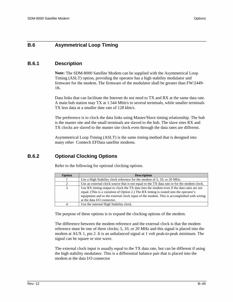
SDM-8000 Satellite Modem Options
Rev. 12 B–45
B.6 Asymmetrical Loop Timing
B.6.1 Description
Note: The SDM-8000 Satellite Modem can be supplied with the Asymmetrical LoopTiming (ASLT) option, providing the operator has a high stability modulator andfirmware for the modem. The firmware of the modulator shall be greater than FW/2449-1K.
Data links that can facilitate the Internet do not need to TX and RX at the same data rate.A main hub station may TX at 1.544 Mbit/s to several terminals, while smaller terminalsTX less data at a smaller date rate of 128 kbit/s.
The preference is to clock the data links using Master/Slave timing relationship. The hubis the master site and the small terminals are slaved to the hub. The slave sites RX andTX clocks are slaved to the master site clock even through the data rates are different.
Asymmetrical Loop Timing (ASLT) is the same timing method that is designed intomany other Comtech EFData satellite modems.
B.6.2 Optional Clocking Options
Refer to the following for optional clocking options.
Option Description1 Use a High Stability clock reference for the modem of 5, 10, or 20 MHz.2 Use an external clock source that is not equal to the TX data rate or for the modem clock.3 Use RX timing output to clock the TX data into the modem even if the data rates are not
equal. (This is a variation of Option 2.) The RX timing is routed into the operator’sequipment and to the external clock input of the modem. This is accomplished with wiringat the data I/O connector.
4 Use the internal High Stability clock.
The purpose of these options is to expand the clocking options of the modem.
The difference between the modem reference and the external clock is that the modemreference must be one of three clocks; 5, 10, or 20 MHz and this signal is placed into themodem at AUX 1, pin 2. It is an unbalanced signal at 1 volt peak-to-peak minimum. Thesignal can be square or sine wave.
The external clock input is usually equal to the TX data rate, but can be different if usingthe high stability modulator. This is a differential balance pair that is placed into themodem at the data I/O connector

Options SDM-8000 Satellite Modem
B–46 Rev. 12
Many ASYNC sateillite links can use this modulator PCB. The TX data rate can bedifferent from the RX data, but the link can be clocked from one clock source.
B.6.3 Internal SCT Clock
Refer to Figure B-26 for an example of the PLL synthesizing the SCT clock from theavailable input sources.
INTERNALHIGH STABILITY
OSC
5, 10, or 20 MHz
EXTERNAL CLOCKINPUT AT THE
DATA I/O
MODULATORREF SWITCH
1. INTERNAL
2. EXT AT AUX 1, PIN 2
SCT PLLREFERENCE
SWITCH
1. MOD REF
2. EXT REF INPUT AT THE DATA I/O MASTER CLOCK
DIVIDED BYCIRCUIT.
PHASE LOCKLOOP.
RX DIVIDED BYPHASE LOCK LOOP
RX INPUT CLOCKOPTIONS ARE:
TX TERRESTRIALSCTEXT
RX SATELLITEINSERT (D&I)
DIVIDED BYCIRCUIT. PHASE
LOCK LOOP.
RX BUFFERRX TIMING
HIGH STABILITY MODULATOR
INTERFACE CARD WITH RX BUFFER
EXIT
SCT
SCT
EXT
Figure B-26. Internal SCT Clock

SDM-8000 Satellite Modem Options
Rev. 12 B–47
Examples:
1. 10 MHz Site Clock is used as the modem reference.
Command ResponseSet CONFIG/MOD/SCT PLL to MODULATOR REFSet CONFIG/MOD/MODULATOR REF to 10 MHzSet CONFIG/INTERFACE/TX CLOCK to TX TERRESTRIAL. (SCT internal
also is valid, but TX terrrestrial is preferred, because of the phase changes thatoccur due to the cables used and their lengths.)
Set CONFIG/INTERFACE/BUFFER CLK to SCT INTERNALSet CONFIG/INTERFACE/BUFFER SIZE to 4 to 6 MillisecondsInput The 10 MHz clock at AUX 1 (P9), pin 2. (Use pin 5, 6, or 8 for GND. EXT
REF is an unbalanced input and should be at least 1 volt peak-to-peak.)
The operator may have equipment that has different data rates, but want toutilize the clock from the modem. RX timing will clock the data going into theoperator’s equipment and Send timing, which is phase locked to the modem RXtiming, will clock the data out of the operator’s equipment. This is calledAsymmetrical Loop Timing.
2. The following represents a slave modem that is using the clock from a distantend modem.
Command ResponseSet CONFIG/MOD/SCT PLL REF to EXT REF FREQ.Set CONFIG/INTERFACE/EXT REF FREQ to RX DATA RATE.Set CONFIG/INTERFACE/TCX CLOCK to TX TERRESTRIAL (The operator
may use SCT Internal because the internal SCT clock is phase locked to theclock coming in at the EXT/MASTER Clock input. TX Terrestrial ispreferred because of phase changes that occur due to cables utilized and theirlengths.)
Set CONFIG/INTERFACE/BUFFER CLOCK to RX SATELLITE.Buffer Size Not Applicable (Because the buffer is in BYPASS when set to RX
SATELLITE.)
Tie RT to EXT/MASTER Clock input at the cable or at the breakout panel(BOP) data connectors. If using the UB-300 BOP, the RT and EXT/MASTERCLOCK appears on all the data connectors. The same can be done with theSMS-700 Switch, as follows:
UB-300 J3, Pins 17 to 23 and Pins 19 to 22SMS-7000 J1, Pins 17 to 20 and Pins 9 to 23

Options SDM-8000 Satellite Modem
B–48 Rev. 12
3. The operator has a clock at the T1 or E1 rate but the TX data rate is different.
Command ResponseSet CONFIG/MOD/SCT PLL REF to EXT REF FREQSet CONFIG/INTERFACE/EXT REF FREQ to the T1 or E1 rate.Set TX CLOCK SOURCE nad the RX BUFFER as desired.Input T1 or E1 Clock at the EXT/MASTER CLOCK pins of the data connector.

Rev. 12 C–1
CAppendix C. SPECIFICATIONS
This appendix describes the modem specifications.
C.1 Specifications
C.1.1 General Specification
Table C-1 lists the general specifications of the modem.
Note: Local control of all remote functions are included by push-button entry.
Table C-1. General Specifications
General SpecificationsOperating Frequency Range 50 to 180 MHz
Synthesized in 2.5 kHz stepsTransmit Frequency Stability ± 10 PPM
± 0.1 PPM (Optional)Modulation Types QPSK
BPSK8PSK16QAM(Front panel selection)
Phase Noise dBm/Hz Distance from Carrier-66.0 100 Hz-76.0 1 kHz-86.0 10 kHz-96.0 100 kHz-96.0 1 MHz
Transmit IF Output Switch 0 to 500 MHzMeasured in 3.0 MHz bandwidth

Specifications SDM-8000 Satellite Modem
C–2 Rev. 12
Table C-2. General Specifications (Continued)
General SpecificationsBaseband Interface EIA-422/EIA-449
MIL-STD-188V.35G.703 — 1.544 Mbit/sG.703 — 2.048 Mbit/sG.703 — 6.312 Mbit/sG.703 — 8.448 Mbit/s(Field selectable in ± 100 bit/s)
Elastic Buffer 32 to 262144 bits or 1 to 32 msSelectable from front panel in bits or ms
Digital Data Rate 9.6 kbit/s to 9.312 Mbit/s 1 bit steps(Front panel selection)
Symbol Data Rate 19 kS/s to 6.3 MS/sScrambling/Descrambling Types IESS-309 (Synchronous 215)
(CCITT) V.35 (EFData, ComstreamFairchild , Linkabit , and Hughes compatible)
Forward Error Correction Viterbi K=7: Rate 1/2, 3/4, 7/8Sequential: Rate 1/2, 3/4, 7/8Pragmatic Trellis: Rate 2/3 or 5/6 (8PSK only)Uncoded: Rate 1/1Reed-Solomon: Concantinated)
M&C Front panel display (16 character by 2 rows)Modulated IF Output Shape
Filter Mask Types: INTELSAT/EUTELSATClosed net ( Comtech EFDataa)Closed net (Fairchild compatible)Closed net (Hughes compatible)
ESC IDRIBSNone(Field selectable)
Diagnostic Features IF LoopbackRF LoopbackBaseband LoopbackInterface LoopbackFault monitoring (includes current and stored faults)BER monitoringInput IF power monitoringBuffer fill status monitoringRemote control via serial port
Power Prime power 90 to 264 VAC, 47 to 63 Hz,130W maximum fused at 2A
Physical:Size
Weight
3.5” H x 19.0” W x 21.5” D (2RU)(9 cm x 48cm x 55 cm )19 lbs. (8.6 kg)
Environmental:TemperatureHumidity
0 to 50°C (+32° to 122°F)0 to 95%, non-condensing

SDM-8000 Satellite Modem Specifications
Rev. 12 C–3
Table C-3. General Specifications (Continued)
Additional Modulator SpecificationsTransmit IF Power -5 to -30 dBm, adjustable in 0.1 dB steps
+5 to -20 dBm high power output (optional)Modulator Power Offset 0 to ± 99 dB
Measured in 0.1 dB stepsSpurious Emmissions -5 to –30 dBm TX output option:
( 0 to 500 MHz)+5 to –20 dBm TX output option:0 to 500 MHz , Symbol Rates ≥ 64 kbit/s0 to 500 MHz, Symbol Rates ≤ 64 kbit/s
-55 dBm
-55 dBm-50 dBm
Output Impedance 50 or 75ΩOutput Return Loss ≤ -17 dB (for 50Ω); ≤ -20 dB (for 75Ω)Output Frequency Stability ± 10 PPMTransmit IF Test Modes CW – Outputs a single carrier at the defined frequency.
Offset – Dual sideband signal with upper sideband and carriersuppressed –30 dBc.
Data Clock Source Internal, ± 1 x 10⁻⁵ stabilityInternal High-Stability ± 2 x 10⁻⁷ (optional)External (optional)
Additional Demodulator SpecificationsOperating Channel Spacing Less than 0.5 dB degradation operating with 2 adjacent like
channels, each 10 dB higher at 1.3 times the symbol rateReceive Input Power (Desired Carrier) -30 to –50 dBm
-30 to –45 dBm< 2 Mbit/s Symbol Rate> 2 Mbit/s Symbol Rate
Receive Input Power (Composite) 1. The sum of all carriers is ≤ -5 dBm.2. The sum of all carriers within 10 MHz from the desired is ≤ +30 dBc.3. The sum of all carriers is ≤ +40 dBc.
IF Input Overload The unit can be damaged by continous RX IF input of 0 dBm.Input Impedance 75Ω (50Ω Optional)Input Return Loss ≤ -17 dB (for 50Ω); ≤ -20 dB (for 75Ω)Carrier Acquisition Range ± 30 kHz minimumClock Acquisition Range ± 100 PPM

Specifications SDM-8000 Satellite Modem
C–4 Rev. 12
Table C-4. General Specifications (Continued)
Remote Control SpecificationsSerial Interface EIA-232 or EIA-485Baud Rate 110 to 19200 Mbit/sSignals Controlled Transmit Frequency
Receive FrequencyTransmit PowerTransmitter On/OffData Rate SelectRF LoopbackIF LoopbackBaseband LoopbackInterface LoopbackTransmit and Receive Filter MaskScrambler TypeScrambler ON/OFFDescrambler TypeDescrambler ON/OFFBuffer Clock TX/RX/INT/HS/INS (D&I only)Transmit Clock Internal/ExternalReceive Clock Normal/InvertDifferential Encoding and DecodingCode and Decode RateTransmit and Receive Overhead TypeAcquisition Sweep ParametersBuffer TypeIDR Backward Alarm Control On/OffReed-Solomon ON/OFFMod and Demod Spectrum Norm/InvertRev Emulation Current/Functional
Signals Monitored Raw Error RateCorrected BERReceive Eb/N0Receive Signal LevelReceive Carrier DetectPower Supply VoltagesFault StatusStored Fault Status
Configuration Retention Will maintain current configuration for up to one year withoutpower
Addressing Programmable to 1 of 255 possibilitiesAddress 0 reserved for global addressing

SDM-8000 Satellite Modem Specifications
Rev. 12 C–5
C.1.2 BER Performance
Table C-5 list the Bit Energy-to-Noise Ratio (Eb/N0 ) required to achieve 10-3 to 10-10 BitError Rates (BER).
Table C-5. BER Performance
Table DescriptionC-3 Noise, Viterbi Decoder, and IDR ModeC-4 Noise, Viterbi Decoder, IBS, and D&I ModeC-5 Noise, Sequential Decoder, BPSK, QPSK, and 56 kbit/sC-6 Noise, Sequential Decoder, BPSK, QPSK, and 1544 kbit/sC-7 Noise, and Reed-SolomonC-8 Noise, Viterbi Decoder, and 8PSK 2/3C-9 Noise, Viterbi Decoder, and 8PSK 5/6C-10 Noise, ViterbiDecoder, and 16QAM
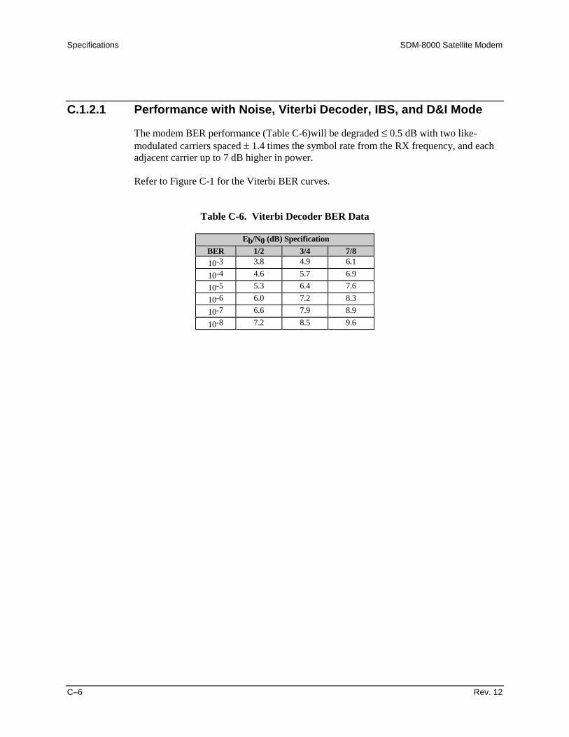
Specifications SDM-8000 Satellite Modem
C–6 Rev. 12
C.1.2.1 Performance with Noise, Viterbi Decoder, IBS, and D&I Mode
The modem BER performance (Table C-6)will be degraded ≤ 0.5 dB with two like-modulated carriers spaced ± 1.4 times the symbol rate from the RX frequency, and eachadjacent carrier up to 7 dB higher in power.
Refer to Figure C-1 for the Viterbi BER curves.
Table C-6. Viterbi Decoder BER Data
Eb/N0 (dB) SpecificationBER 1/2 3/4 7/810-3 3.8 4.9 6.1
10-4 4.6 5.7 6.9
10-5 5.3 6.4 7.6
10-6 6.0 7.2 8.3
10-7 6.6 7.9 8.9
10-8 7.2 8.5 9.6

SDM-8000 Satellite Modem Specifications
Rev. 12 C–7
10-4
10-3
10-5
10-6
BER
10-7
10-9
10-8
10-10
3.0 4.0 5.0 6.0Eb/N0 (dB)
7.0 8.0 9.0 10.0 11.0
10-2
IBS1/2 Rate
IDR3/4 Rate
IDR7/8 Rate
SPECIFICATIONS
Figure C-1. Viterbi BER , IBS, and D&I Mode Performance Curves
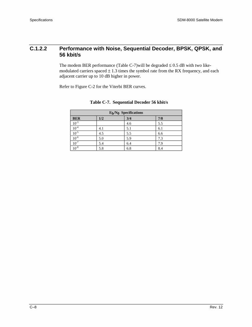
Specifications SDM-8000 Satellite Modem
C–8 Rev. 12
C.1.2.2 Performance with Noise, Sequential Decoder, BPSK, QPSK, and56 kbit/s
The modem BER performance (Table C-7)will be degraded ≤ 0.5 dB with two like-modulated carriers spaced ± 1.3 times the symbol rate from the RX frequency, and eachadjacent carrier up to 10 dB higher in power.
Refer to Figure C-2 for the Viterbi BER curves.
Table C-7. Sequential Decoder 56 kbit/s
Eb/N0 SpecificationsBER 1/2 3/4 7/810-3 4.6 5.510-4 4.1 5.1 6.110-5 4.5 5.5 6.610-6 5.0 5.9 7.310-7 5.4 6.4 7.910-8 5.8 6.8 8.4
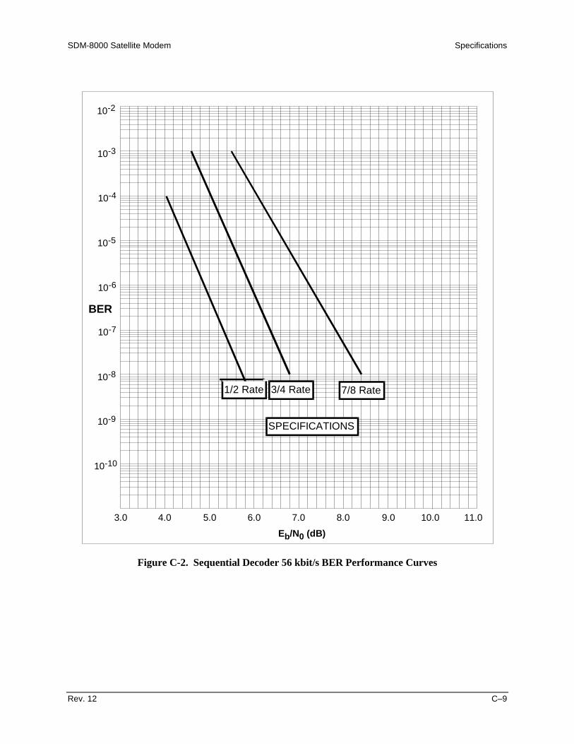
SDM-8000 Satellite Modem Specifications
Rev. 12 C–9
10-4
10-3
10-5
10-6
BER
10-7
10-9
10-8
10-10
3.0 4.0 5.0 6.0Eb/N0 (dB)
7.0 8.0 9.0 10.0 11.0
10-2
1/2 Rate 3/4 Rate 7/8 Rate
SPECIFICATIONS
Figure C-2. Sequential Decoder 56 kbit/s BER Performance Curves
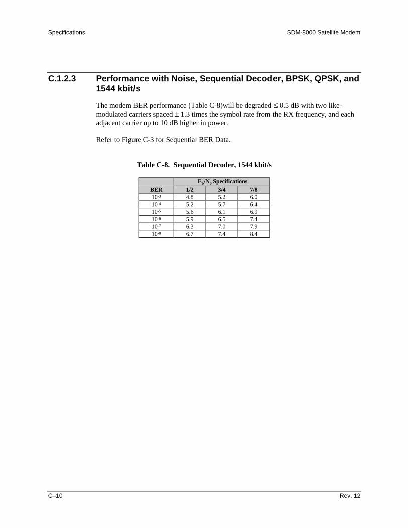
Specifications SDM-8000 Satellite Modem
C–10 Rev. 12
C.1.2.3 Performance with Noise, Sequential Decoder, BPSK, QPSK, and1544 kbit/s
The modem BER performance (Table C-8)will be degraded ≤ 0.5 dB with two like-modulated carriers spaced ± 1.3 times the symbol rate from the RX frequency, and eachadjacent carrier up to 10 dB higher in power.
Refer to Figure C-3 for Sequential BER Data.
Table C-8. Sequential Decoder, 1544 kbit/s
Eb/N0 SpecificationsBER 1/2 3/4 7/810-3 4.8 5.2 6.010-4 5.2 5.7 6.410-5 5.6 6.1 6.910-6 5.9 6.5 7.410-7 6.3 7.0 7.910-8 6.7 7.4 8.4
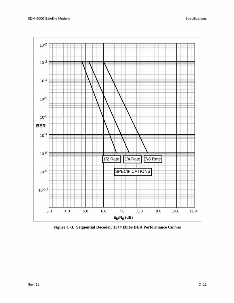
SDM-8000 Satellite Modem Specifications
Rev. 12 C–11
10-4
10-3
10-5
10-6
BER
10-7
10-9
10-8
10-10
3.0 4.0 5.0 6.0Eb/N0 (dB)
7.0 8.0 9.0 10.0 11.0
10-2
1/2 Rate 3/4 Rate 7/8 Rate
SPECIFICATIONS
Figure C-3. Sequential Decoder, 1544 kbit/s BER Performance Curves
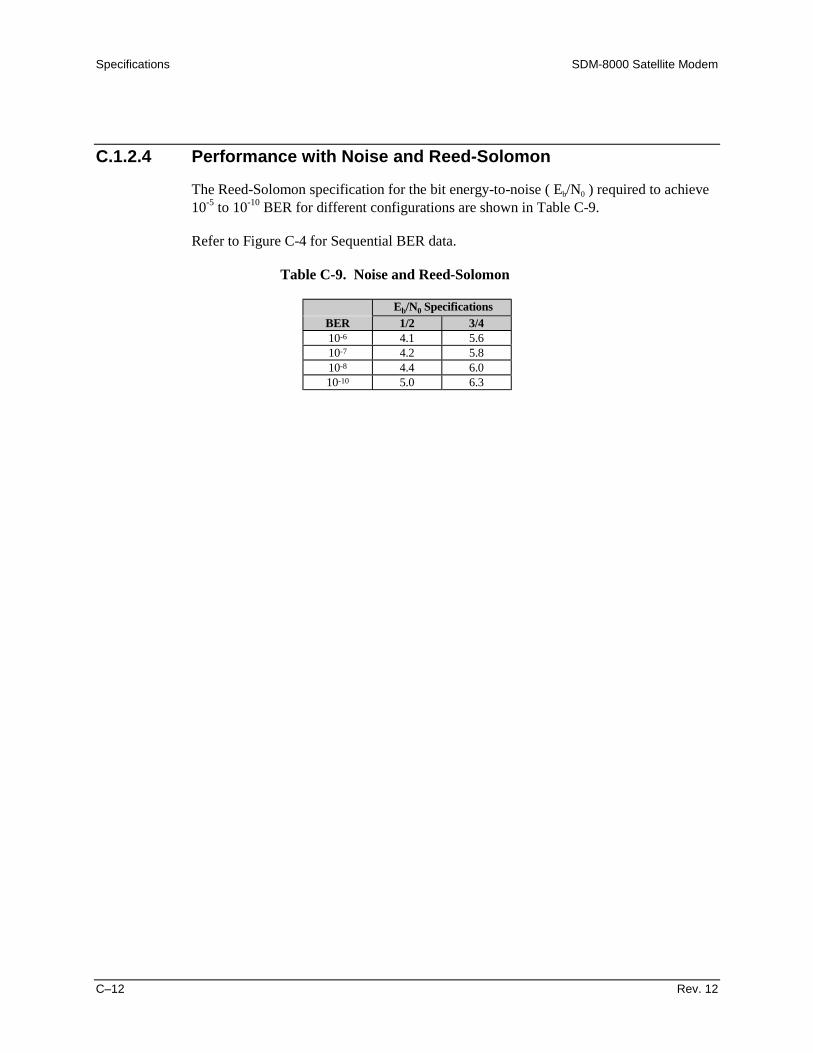
Specifications SDM-8000 Satellite Modem
C–12 Rev. 12
C.1.2.4 Performance with Noise and Reed-Solomon
The Reed-Solomon specification for the bit energy-to-noise ( Eb/N0 ) required to achieve10-5 to 10-10 BER for different configurations are shown in Table C-9.
Refer to Figure C-4 for Sequential BER data.
Table C-9. Noise and Reed-Solomon
Eb/N0 SpecificationsBER 1/2 3/410-6 4.1 5.610-7 4.2 5.810-8 4.4 6.010-10 5.0 6.3

SDM-8000 Satellite Modem Specifications
Rev. 12 C–13
10-4
10-5
10-6
BER
10-7
10-9
10-8
10-10
Eb/N0 (dB)7.05.04.0 8.06.0 9.0 10.0 11.0
3/4 RATE
1/2 RATE
Figure C-4. Noise and Reed-Solomon

Specifications SDM-8000 Satellite Modem
C–14 Rev. 12
C.1.2.5 Performance with Noise, Viterbi Decoder, and 8PSK 2/3
The specification for the Eb/N0 required to achieve 10-4 to 10-9 BER for differentconfigurations are shown in Table C-10.
Refer to Figure C-5 for Noise, ViterbiDecoder, and 8PSK 2/3.
Table C-10. Viterbi Decoder and 8PSK 2/3
Eb/N0 (dB) SpecificationsBER Reed-Solomon Without Reed-Solomon10-4 5.5 7.010-5 5.8 7.810-6 6.2 8.710-7 6.5 9.510-8 6.7 10.210-9 6.9

SDM-8000 Satellite Modem Specifications
Rev. 12 C–15
10-4
10-5
10-6
BER
10-7
10-9
10-8
10-10
Eb/N0 (dB)7.05.0 8.06.0 9.0 10.0 11.0
WITHOUTREED-SOLOMAN
WITHREED-SOLOMAN
Figure C-5. Noise, Viterbi Decoder, and 8PSK 2/3 BER Performance Curves

Specifications SDM-8000 Satellite Modem
C–16 Rev. 12
C.1.2.6 Performance with Noise, Viterbi Decoder, and 8PSK 5/6
The specification for the Eb/N0 required to achieve 10-4 to 10-9 BER for differentconfigurations are shown in Table C-11.
Refer to Figure C-6 for Viterbi Decoder and 8PSK.5/6 BER.
Table C-11. Viterbi Decoder and 8PSK 5/6 BER Data
Eb/N0 (dB) Specifications
Reed-Solomon Without Reed-SolomonBER Eb/N0 BER Eb/N010-4 7.5 10-4 9.010-5 7.8 10-5 10.010-6 8.2 10-6 10.810-7 8.6 10-7 11.510-8 8.8 10-8 12.310-9 9.3 10-9 13.1
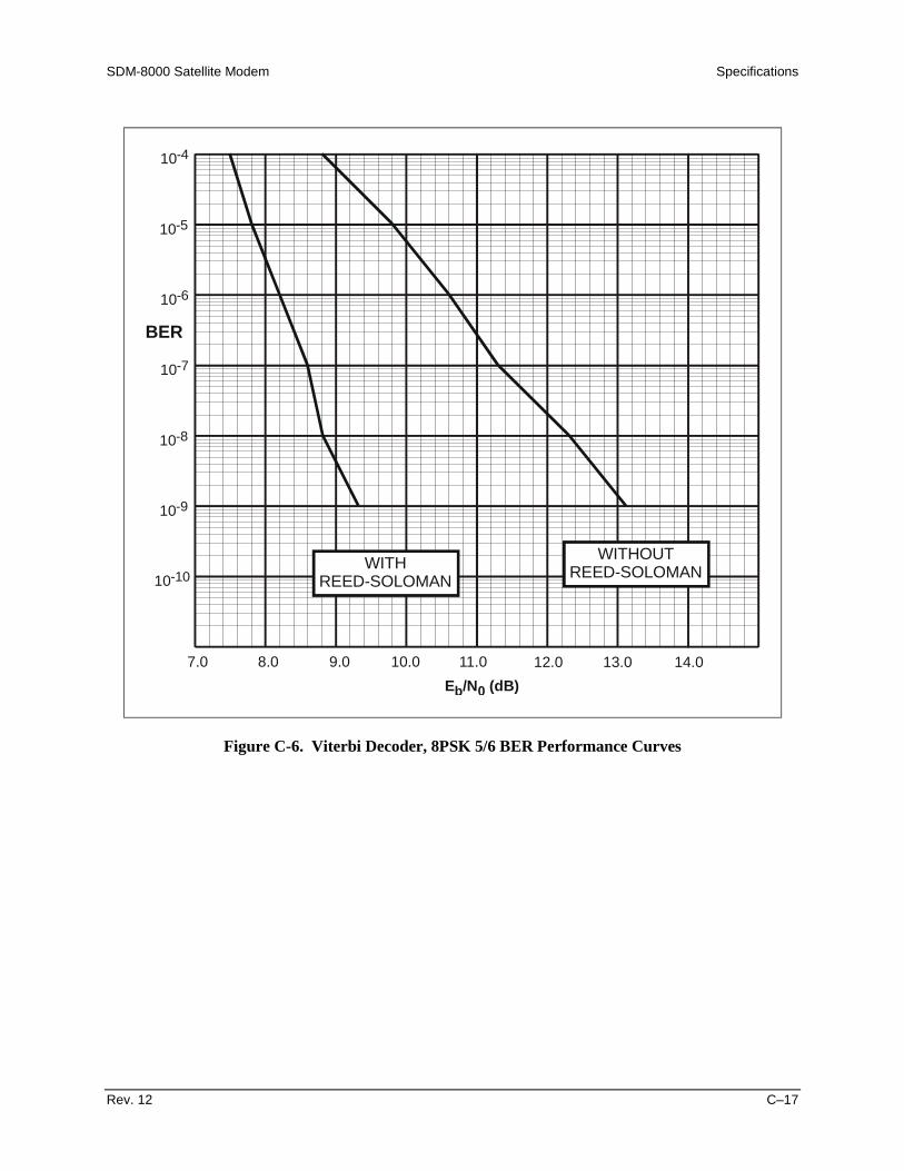
SDM-8000 Satellite Modem Specifications
Rev. 12 C–17
10-4
10-5
10-6
BER
10-7
10-9
10-8
10-10
Eb/N0 (dB)7.0 8.0 9.0 12.010.0 13.011.0 14.0
WITHOUTREED-SOLOMANWITH
REED-SOLOMAN
Figure C-6. Viterbi Decoder, 8PSK 5/6 BER Performance Curves

Specifications SDM-8000 Satellite Modem
C–18 Rev. 12
C.1.2.7 Performance with Noise, Viterbi Decoder, and 16QAM
The specifications for the Eb/N0 requiredd to achieve 10-4 to 10-9 BER for differentconfigurations are shown in Table C-12.
Refer to Figure C-7 for Viterbi Decoder and 16QAM data.
Table C-12. Viterbi Decoder and 16QAM
Eb/N0 (dB) SpecificationsReed-Solomon Without Reed-Solomon
BER 3/4 7/8 3/4 7/810-4 7.9 9.3 9.1 10.410-5 8.1 9.6 10.0 11.210-6 8.4 9.8 10.8 12.010-7 8.6 10.0 11.7 12.810-8 8.8 10.3 12.6 13.610-9 9.2 10.5

SDM-8000 Satellite Modem Specifications
Rev. 12 C–19
10-4
10-5
10-6
BER
10-7
10-9
10-8
10-10
Eb/N0 (dB)7.0 8.0 9.0 12.010.0 13.011.0 14.0
3/4 Rate
3/4 Rate
7/8 Rate
7/8 Rate
WITHOUTREED-SOLOMAN
WITHREED-SOLOMAN
Figure C-7. Viterbi Decoder and 16QAM
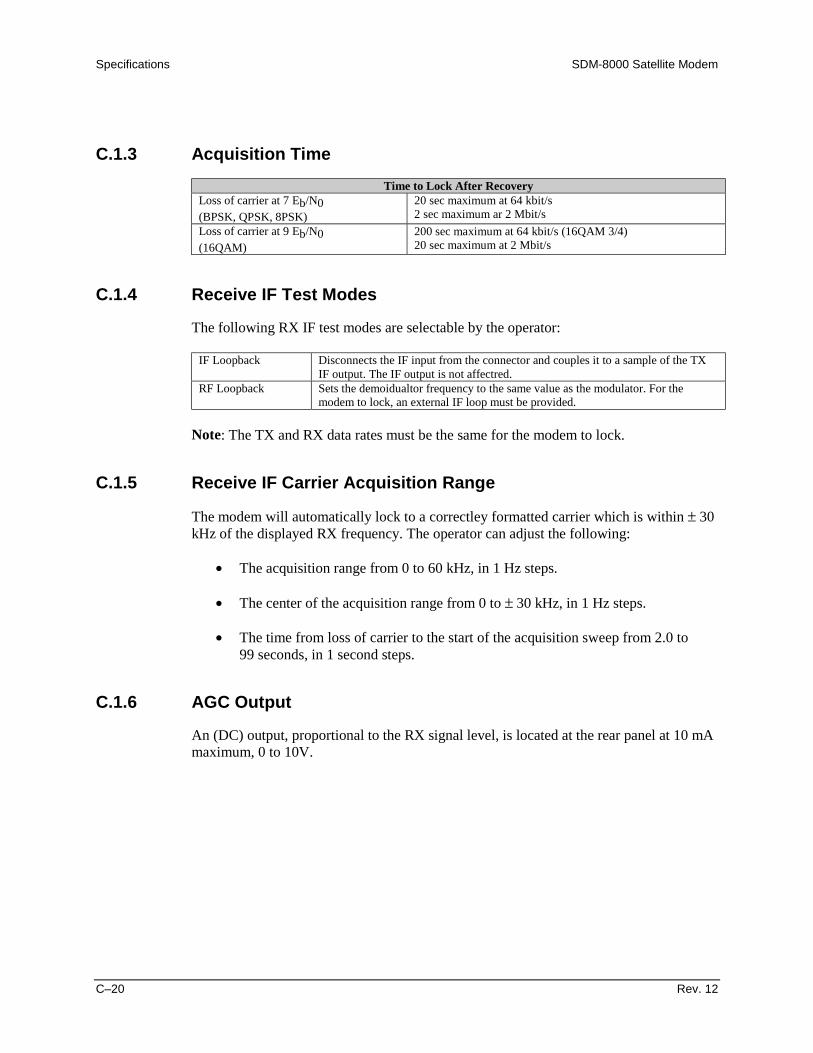
Specifications SDM-8000 Satellite Modem
C–20 Rev. 12
C.1.3 Acquisition TimeTime to Lock After Recovery
Loss of carrier at 7 Eb/N0(BPSK, QPSK, 8PSK)
20 sec maximum at 64 kbit/s2 sec maximum ar 2 Mbit/s
Loss of carrier at 9 Eb/N0(16QAM)
200 sec maximum at 64 kbit/s (16QAM 3/4)20 sec maximum at 2 Mbit/s
C.1.4 Receive IF Test Modes
The following RX IF test modes are selectable by the operator:
IF Loopback Disconnects the IF input from the connector and couples it to a sample of the TXIF output. The IF output is not affectred.
RF Loopback Sets the demoidualtor frequency to the same value as the modulator. For themodem to lock, an external IF loop must be provided.
Note: The TX and RX data rates must be the same for the modem to lock.
C.1.5 Receive IF Carrier Acquisition Range
The modem will automatically lock to a correctley formatted carrier which is within ± 30kHz of the displayed RX frequency. The operator can adjust the following:
• The acquisition range from 0 to 60 kHz, in 1 Hz steps.
• The center of the acquisition range from 0 to ± 30 kHz, in 1 Hz steps.
• The time from loss of carrier to the start of the acquisition sweep from 2.0 to99 seconds, in 1 second steps.
C.1.6 AGC Output
An (DC) output, proportional to the RX signal level, is located at the rear panel at 10 mAmaximum, 0 to 10V.
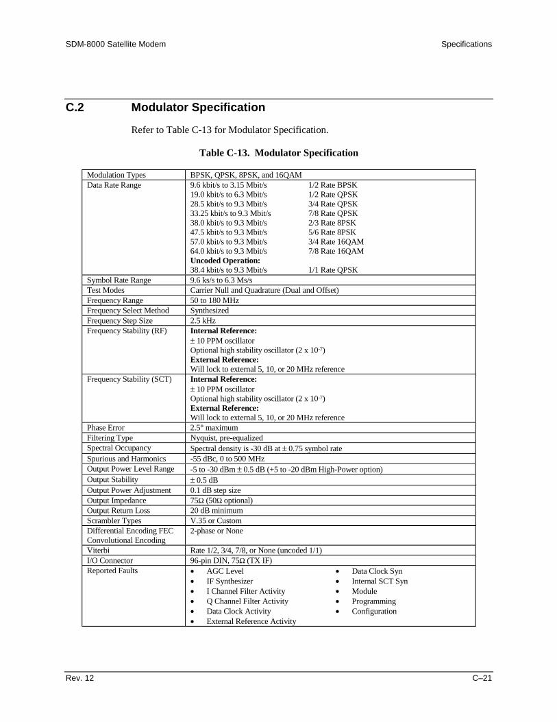
SDM-8000 Satellite Modem Specifications
Rev. 12 C–21
C.2 Modulator Specification
Refer to Table C-13 for Modulator Specification.
Table C-13. Modulator Specification
Modulation Types BPSK, QPSK, 8PSK, and 16QAMData Rate Range 9.6 kbit/s to 3.15 Mbit/s 1/2 Rate BPSK
19.0 kbit/s to 6.3 Mbit/s 1/2 Rate QPSK28.5 kbit/s to 9.3 Mbit/s 3/4 Rate QPSK33.25 kbit/s to 9.3 Mbit/s 7/8 Rate QPSK38.0 kbit/s to 9.3 Mbit/s 2/3 Rate 8PSK47.5 kbit/s to 9.3 Mbit/s 5/6 Rate 8PSK57.0 kbit/s to 9.3 Mbit/s 3/4 Rate 16QAM64.0 kbit/s to 9.3 Mbit/s 7/8 Rate 16QAMUncoded Operation:38.4 kbit/s to 9.3 Mbit/s 1/1 Rate QPSK
Symbol Rate Range 9.6 ks/s to 6.3 Ms/sTest Modes Carrier Null and Quadrature (Dual and Offset)Frequency Range 50 to 180 MHzFrequency Select Method SynthesizedFrequency Step Size 2.5 kHzFrequency Stability (RF) Internal Reference:
± 10 PPM oscillatorOptional high stability oscillator (2 x 10⁻⁷)External Reference:Will lock to external 5, 10, or 20 MHz reference
Frequency Stability (SCT) Internal Reference:± 10 PPM oscillatorOptional high stability oscillator (2 x 10⁻⁷)External Reference:Will lock to external 5, 10, or 20 MHz reference
Phase Error 2.5° maximumFiltering Type Nyquist, pre-equalizedSpectral Occupancy Spectral density is -30 dB at ± 0.75 symbol rateSpurious and Harmonics -55 dBc, 0 to 500 MHzOutput Power Level Range -5 to -30 dBm ± 0.5 dB (+5 to -20 dBm High-Power option)Output Stability ± 0.5 dBOutput Power Adjustment 0.1 dB step sizeOutput Impedance 75Ω (50Ω optional)Output Return Loss 20 dB minimumScrambler Types V.35 or CustomDifferential Encoding FECConvolutional Encoding
2-phase or None
Viterbi Rate 1/2, 3/4, 7/8, or None (uncoded 1/1)I/O Connector 96-pin DIN, 75Ω (TX IF)Reported Faults • AGC Level
• IF Synthesizer• I Channel Filter Activity• Q Channel Filter Activity• Data Clock Activity• External Reference Activity
• Data Clock Syn• Internal SCT Syn• Module• Programming• Configuration

Specifications SDM-8000 Satellite Modem
C–22 Rev. 12
C.3 Demodulator Specifications
Refer to Table C-14 for demodulator specifications.
Table C-14. Demodulator Specification
Modulation Types BPSK, QPSK, 8PSK, and 16QAMData Rate Range 9.6 kbit/s to 3.15 Mbit/s 1/2 Rate BPSK
19.0 kbit/s to 6.3 Mbit/s 1/2 Rate QPSK28.5 kbit/s to 9.3 Mbit/s 3/4 Rate QPSK33.25 kbit/s to 9.3 Mbit/s 7/8 Rate QPSK38.0 kbit/s to 9.3 Mbit/s 2/3 Rate 8PSK47.5 kbit/s to 9.3 Mbit/s 5/6 Rate 8PSK57.0 kbit/s to 9.3 Mbit/s 3/4 Rate 16QAM64.0 kbit/s to 9.3 Mbit/s 7/8 Rate 16QAM
Uncoded Operation:38.4 kbit/s to 9.3 Mbit/s 1/1 Rate QPSK
Symbol Rate Range 9.6 ks/s to 6.3 Ms/sIF Frequency 50 to 180 MHz, in 2.5 kHz stepsInput Level -30 to -55 dBmDecoding Type Viterbi − 1/2, 3/4, 7/8
Sequential − 1/2, 3/4, 7/8Uncoded − 1/1Field changeableCode rates selectable from front panel
Filter Masks Open net (INTELSAT or EUTELSAT)EFD Closed netCustom
Descrambler Types V.35 or CustomReported Faults Carrier Detect
DescramblerIF SynthesizerBER ThresholdRX Clock SynModuleI ChannelQ ChannelProgrammingConfiguration
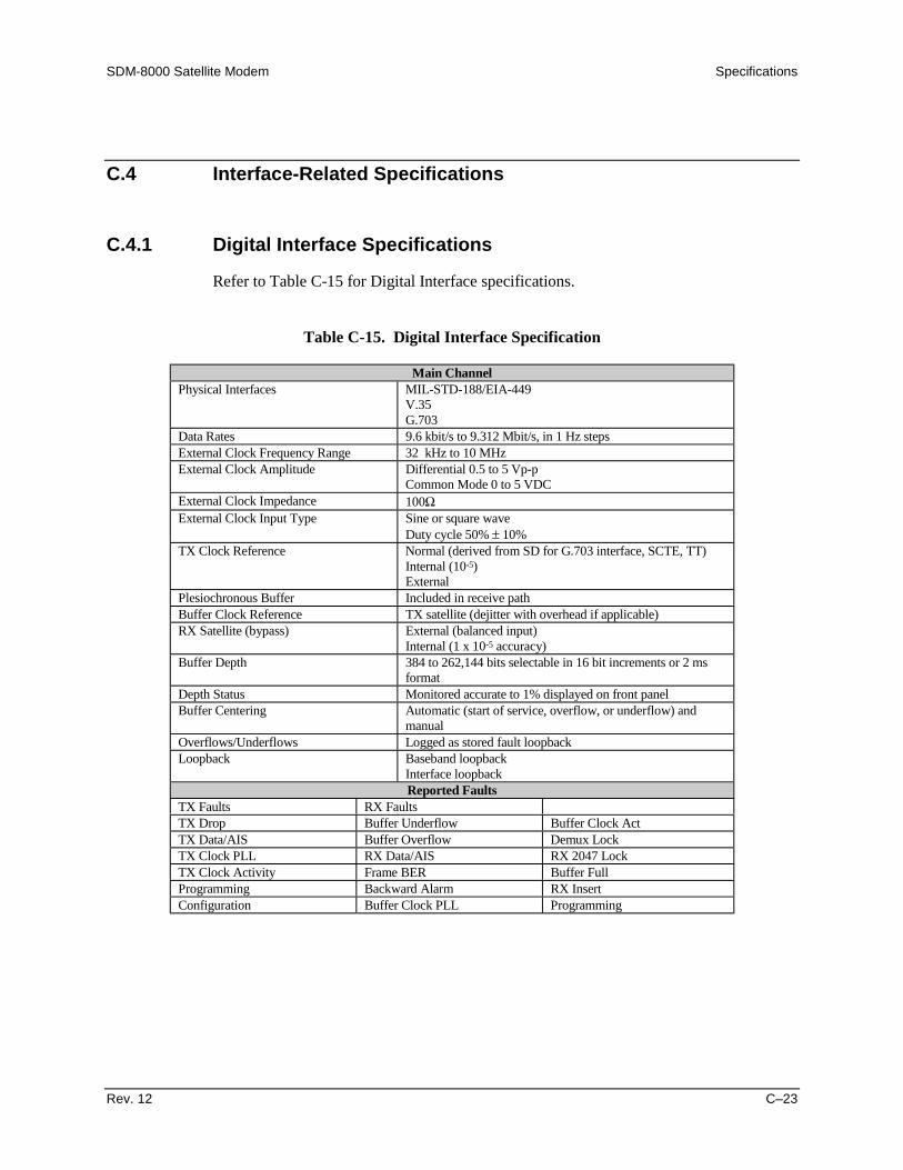
SDM-8000 Satellite Modem Specifications
Rev. 12 C–23
C.4 Interface-Related Specifications
C.4.1 Digital Interface Specifications
Refer to Table C-15 for Digital Interface specifications.
Table C-15. Digital Interface Specification
Main ChannelPhysical Interfaces MIL-STD-188/EIA-449
V.35G.703
Data Rates 9.6 kbit/s to 9.312 Mbit/s, in 1 Hz stepsExternal Clock Frequency Range 32 kHz to 10 MHzExternal Clock Amplitude Differential 0.5 to 5 Vp-p
Common Mode 0 to 5 VDCExternal Clock Impedance 100ΩExternal Clock Input Type Sine or square wave
Duty cycle 50% ± 10%TX Clock Reference Normal (derived from SD for G.703 interface, SCTE, TT)
Internal (10-5)External
Plesiochronous Buffer Included in receive pathBuffer Clock Reference TX satellite (dejitter with overhead if applicable)RX Satellite (bypass) External (balanced input)
Internal (1 x 10⁻⁵ accuracy)Buffer Depth 384 to 262,144 bits selectable in 16 bit increments or 2 ms
formatDepth Status Monitored accurate to 1% displayed on front panelBuffer Centering Automatic (start of service, overflow, or underflow) and
manualOverflows/Underflows Logged as stored fault loopbackLoopback Baseband loopback
Interface loopbackReported Faults
TX Faults RX FaultsTX Drop Buffer Underflow Buffer Clock ActTX Data/AIS Buffer Overflow Demux LockTX Clock PLL RX Data/AIS RX 2047 LockTX Clock Activity Frame BER Buffer FullProgramming Backward Alarm RX InsertConfiguration Buffer Clock PLL Programming
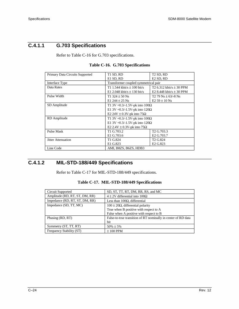
Specifications SDM-8000 Satellite Modem
C–24 Rev. 12
C.4.1.1 G.703 Specifications
Refer to Table C-16 for G.703 specifications.
Table C-16. G.703 Specifications
Primary Data Circuits Supported T1 SD, RDE1 SD, RD
T2 SD, RDE2 SD, RD
Interface Type Transformer coupled symmetrical pairData Rates T1 1.544 kbit/s ± 100 bit/s
E1 2.048 kbit/s ± 130 bit/sT2 6.312 kbit/s ± 30 PPME2 8.448 kbit/s ± 30 PPM
Pulse Width T1 324 ± 50 NsE1 244 ± 25 Ns
T2 79 Ns ± 63/-8 NsE2 59 ± 10 Ns
SD Amplitude T1 3V +0.3/-1.5V-pk into 100ΩE1 3V +0.3/-1.5V-pk into 120ΩE2 24V ± 0.3V-pk into 75Ω
RD Amplitude T1 3V +0.3/-1.5V-pk into 100ΩE1 3V +0.3/-1.5V-pk into 120ΩE2 2.4V ± 0.3V-pk into 75Ω
Pulse Mask T1 G.703.2E1 G.703.6
T2 G.703.3E2 G.703.7
Jitter Attenuation T1 G.824E1 G.823
T2 G.824E2 G.823
Line Code AMI, B8ZS, B6ZS, HDB3
C.4.1.2 MIL-STD-188/449 Specifications
Refer to Table C-17 for MIL-STD-188/449 specifications.
Table C-17. MIL-STD-188/449 Specifications
Circuit Supported SD, ST, TT, RT, DM, RR, RS, and MCAmplitude (RD, RT, ST, DM, RR) 4 ± 2V differential into 100ΩImpedance (RD, RT, ST, DM, RR) Less than 100Ω, differentialImpedance (SD, TT, MC) 100 ± 20Ω, differential polarity
True when B positive with respect to AFalse when A positive with respect to B
Phasing (RD, RT) False-to-true transition of RT nominally in center of RD databit
Symmetry (ST, TT, RT) 50% ± 5%Frequency Stability (ST) ± 100 PPM

SDM-8000 Satellite Modem Specifications
Rev. 12 C–25
C.4.1.3 V.35 Specifications
Refer to Table C-18 for V.35 specifications.
Table C-18. V.35 Specifications
Circuit Supported SD, SCT, SCTE, RD, SCR, DSR, RLSD, RTS, CTS, and MCAmplitude (RD, SCR, SCT, SD, SCTE) ± 55V-pk ± 20% differential, into 100ΩAmplitude (CTS, DSR, RLSD) ±10 ± 5V into ± 5000 ± 2000ΩImpedance (RD, SCR, SCT) 100 ± 255 > 20Ω, differentialImpedance (SD, SCTE) 100 ± 10Ω, differentialImpedance (RTS) 5000 ± 2000Ω, < 2500 PFDC Offset (RD, SCR, SCT) ± 0.6V max, 1000Ω termination to groundPolarity (SD, SCT, SCTE, RD, SCR) True when B positive with respect to A
False when A positive with respect to BPolarity (RTS, CTS, DSR, RLSD) True when < -3V with respect to ground
False when > +3V with respect to groundPhasing (SCTE, SCR) False-to-True transition nominally in center of data bitSymmetry (SCT, SCTE, SCR) 50% ± 5%
C.4.1.4 IDR Interface Specifications
Refer to Table C-19 for IDR Interface specifications.
Table C-19. IDR Interface Specifications
Composite Data Rates SupportedIDR 1.640 Mbit/s
2.144 Mbit/s6.408 Mbit/s8.544 Mbit/s
Primary Data Rates SupportedG.703 1.544 kbit/s
2.048 kbit/s6.312 kbit/s8.448 kbit/s
Engineering Service ChannelESC Audio 2 duplex ADPCM channelsAudio Encoding CCITT G.721Audio Interface Type 600Ω transformer-balanced 4-wireAudio Input Level -20 to +10 dBm for 0 dBm, 1 dB stepsAudio Output Level -20 to +10 dBm for 0 dBm, 1 dB stepsAuto Filtering Internal 300 to 3400 Hz input and outputESC Data Interface Type EIA-422ESC Data Rate 8 kbit/sESC Data Circuits Supported SD, ST, RD, RT, Octet In, and Octet OutOcetet Timing Octet high in with every 8th bit, aligns with frame bit d864 kbit/s Data Interface Type EIA-42264 kbit/s Data Rate 64 kbit/s64 kbit/s Data Circuits Supported SD, ST, RD, and RT64 kbit/s Data Signal Phasing Per EIA-449, Data changes on the rising clock transition, is sampled on
the falling clock edge64 kbit/s Octet Timing Octet aligned with rising edge of ESC clock.

Specifications SDM-8000 Satellite Modem
C–26 Rev. 12
Faults and AlarmsBackward Alarms Supported 4 input, 4 outputBackward Alarm Inputs 1kΩ pull up to +5V, set below 2V to clearBackward Alarm Outputs FORM C Relay, NO, NC, CDemodulator Fault Relay NO, C contacts available for backward alarm inputsDeferred Maintenance Alarm Open collector, high impedance IF fault, 15V max, 20 mA maximum
C.4.1.5 IBS Interface Specification
Refer to Table C-20 for IBS Interface specifications.
Table C-20. IBS Interface Specifications
Composite Data Rates Supported N x 64 kbit/s from 64 kbit/s to 2048 kbit/s with 1/15overhead
Primary Data Circuits SupportedG.703 Format
G.703 1.544 Mbit/s ± 100 bit/s SD, RDG.703 2.048 Mbit/s ± 130 bit/s SD, RD
Primary Data Circuits Supported MIL-STD-188/449 and V.35 Format
N x 64 kbit/s to 2.048 Mbit/s and 1/544 Mbit/s
Engineering Service ChannelEarth Station-to-Earth Station Channel EIA-232 TD, RD, DSR, RTS
Asynchronously sampled at 1/512 of the primary channeldata rate for a usable data rate equal to 1/2000 of the primarychannel data rate
EIA-232 SpecificationCircuit Supported RD, TD, DSR, RTS, CTSAmplitude (RD, RTS) True: 14V ± 11V
False: -14 V ± 11VAmplitude (TD, DSR, CTS) True: 11V ± 2V
False: -11V ± 2VImpedance 5000 ±2000Ω < 2500 pFBaud Rate Max: 1/2000 times the data rate (refer to Chapter 3 for
details)Faults
Modulator Fault Open collector output 15V maximum, 20 mA maximumcurrent, sink Fault is open circuit
Demodulator Fault Open collector output 15V maximum, 20 mA maximumcurrent, sink fault is open circuit
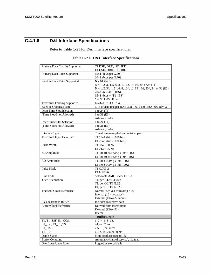
SDM-8000 Satellite Modem Specifications
Rev. 12 C–27
C.4.1.6 D&I Interface Specifications
Refer to Table C-21 for D&I Interface specifications.
Table C-21. D&I Interface Specifications
Primary Data Circuits Supported T1 DSD, DRD, ISD, IRDE1 DSD, DRD, ISD, IRD
Primary Data Rates Supported 1544 kbit/s per G.7032048 kbit/s per G.703
Satellite Data Rates Supported N x 64 kbit/sN = 1, 2, 3, 4, 5, 6, 8, 10, 12, 15, 16, 20, or 24 (T1)N = 1, 2, 3*, 4, 5*, 6, 8, 10*, 12, 15*, 16, 20*, 24, or 30 (E1)2048 kbit/s (E1_IBS)1544 kbit/s + (T1_IBS)* = No CAS allowed
Terrestrial Framing Supported G.732/G.733, G.704Satellite Overhead Rate 1/16 of data rate per IESS-308 Rev. 6 and IESS-309 Rev. 3Drop Time Slot Selection 1 to 24 (T1)(Time Slot 0 not Allowed) 1 to 31 (E1)
Arbitrary orderInsert Time Slot Selection 1 to 24 (T1)(Time Slot 0 not Allowed) 1 to 31 (E1)
Arbitrary orderInterface Type Transformer-coupled symmetrical pairTerrestrial Input Data Rate T1 1544 kbit/s ±100 bit/s
E1 2048 kbit/s ±130 bit/sPulse Width T1 324 ± 50 Ns
E1 244 ± 25 NsSD Amplitude T1 3.0 +0.3/-1.5V-pk into 100Ω
E1 3.0 +0.3/-1.5V-pk into 120ΩRD Amplitude T1 3.0 ± 0.3V-pk into 100Ω
E1 3.0 ± 0.3V-pk into 120ΩPulse Mask T1 G.703.2
E1 G.703.6Line Code Selectable AMI, B8ZS, HDB3Jitter Attenuation T1, per AT&T 43802
T1, per CCITT G.824E1, per CCITT G.823
Transmit Clock Reference Normal (derived from drop SD)Internal (10-5 accuracy)External (EIA-422 input)
Plesiochronous Buffer Included in receive pathBuffer Clock Reference Derived from insert input
External (EIA-422)Internal
Buffer DepthT1, T1_ESF, E1_CCS, 1, 2, 4, 6, 8, 12,E1_IBS, E1_31_TS 24, or 32 msE1_CAS 7.5, 15, or 30 msT1_IBS 6, 12, 18, 24, or 30 msDepth Status Monitored accurate to 1%Buffer Centering Automatic (start of service), manualOverflows/Underflows Logged as stored fault

Specifications SDM-8000 Satellite Modem
C–28 Rev. 12
Engineering Service ChannelESC Data Interface Type EIA-232CESC Data Rate 1/512 of satellite data rate, maximum (over sampled)ESC Data Circuits Supported SD, RD, DSR
Faults and AlarmsBackward Alarms Supported 1 (looped per IESS-309)Backward Alarm Output Sums into secondary alarmModulator Fault Open collector, 15V maximum, 20 mA maximum, used by
protection switch, if in systemDemodulator Fault Open collector, 15V maximum, 20 mA maximum, used by
protection switch, if in system

SDM-8000 Satellite Modem Specifications
Rev. 12 C–29
C.4.1.7 Asynchronous Interface Specifications
Refer to Table C-22 for Asynchronous Interface specifications.
Table C-22. Asynchronous Interface Specifications
Main ChannelPhysical Interface MIL-STD-188(Factory Option) EIA-422/449
V.35G.703
Data Rates 9.6K, 19.2K, 32 kbit/s to 8.448 Mbit/sG.703 Data Rates 1.544 Mbit/s(Jumper Selectable) 2.048 Mbit/s
6.312 Mbit/s8.448 Mbit/s
G.703 Line Code AMI, B8ZS, B6ZS, HDB3Transmit Clock Reference Internal modem reference or external transmit clock (SCT or TT)Jitter Attenuation Per G.703Pulse Mask Per G.703
Overhead ChannelOverhead Rate 16/15 of main channelASYNC Channel Rate (maximum) < 1.875% of main channelASYNC Channel Interface EIA-232C
2-wire EIA-485 half-duplex4-wire EIA-485 full-duplex
Connector 25-pin D on breakout panelBaud Rates, ASYNC 110, 150, 300, 600, 1200, 2400, 4800, 9600, 19200, 38400 bit/sASYNC Format 5, 6, 7, or 8 data bits
Even, odd, or no parity1 or 2 stop bits (1 or 1.5 for 5 bit)
Buffer Specifications (Plesiochronous/Buffer Operation)Buffer Size 384 to 262144 bits, in 16-bit stepsBuffer Fill Status Monitored accurate to ± 1%Buffer Centering Automatic or ManualBuffer Clock Reference Transmit
Internal (10-5 Stability)ExternalReceive (Buffer Bypass)
External Clock Amplitude Differential 0.5 to 5 Vp-pUnbalanced Mode 0 to 5 VDC.
External Clock Frequency 256 to 2048 kHz, in 64 kHz stepsExternal Clock Impedance 100WExternal Clock Input Type Sine or Square wave
50% ± 10%

Specifications SDM-8000 Satellite Modem
C–30 Rev. 12
C.4.1.8 Reed-Solomon Specifications (Optional)
Refer to Table C-23 for Reed-Solomon specifications.
Table C-23. Reed-Solomon Specifications
Primary Data Rates Supported (IDR) 1640 kbit/s (T1)2144 kbit/s (E1)6408 kbit/s (T2)8544 kbit/s (E2)
Satellite Data Rates Supported N x 64 kbit/s(IBS/D&I) N = 1, 2, 3, 4, 6, 8, or 16
C.5 Interface General
C.5.1 Transmit Clock Source
The TX clock is selectable by the operator from the following sources:
• SCT (Internal) ± 10 PPM (from Modulator).
• Terrestrial: Must be ± 130 PPM.
• External: Must be ± 100 PPM (must be locked to data).
• RX satellite clock (Loop Timing). RX data rate must be the same as the TX datarate. Must be ± 100 PPM.
Transmit Clock Source SpecificationsExternal Clock Frequency Range 32 kHz to 10 MHzExternal Clock Amplitude Balanced Mode: 1.0 to 5.0 volts peak-to-peak
Unbalanced Mode: 0.5 to volt peak-to-peak0 VDC Offset
External Clock Impedance 100Ω Balanced75 Ω Unbalanced
External Clock Input Type Sine or Square WaveDuty Cycle: 50 ± 10%
Transmit Clock Switching Due to Failureof Selected Clock
The modem will automatically switch the TX Xloxk source toSCT on failure of the selected clock.
Data Test Pattern Substitutions The operator can substitute the TX data with 2047.
Note: This pattern is only available with IDR/IBS framing.Transmit Data Substitution Due to Fault The operator can select either NONE or AIS TX data
substitution codes.Faults WhichGenerate Data Substitution Refer to Fault Tree, Section C.7.

SDM-8000 Satellite Modem Specifications
Rev. 12 C–31
C.5.2 Buffer Clock
Refer to the following for buffer specifications.
Buffer Clock Source Select from the following:
• TX Terrestrial Clock• RX Satellite Clock• External Clock• SCT, Internal• High Stability
Buffer Clock Source Specification Clocks must be ± 100 PPM.RX Clock Switching Due to Failure ofSelected Clock
Modem will automatically switch the RX clock source tointernal on failure of the selected clock.
RX Clock Adjustment Phase Selectable from either Normal or Inverted.RX Doppler Buffer RX Doppler buffer can be set from 64 to 65,536 bit/s in 16 bit
steps (also selectable in milliseconds).Buffer Centering Selectable to 50% by the operator.Loopback Modes Selectable from one of the following:
• Baseband – Near-end and far-end• Interface – Near-end and far-end• D&I Baseband – Insert data into drop data out.
C.5.3 Switch FaultsModulator Fault Open collector output: 15V maximum, 20 mA maximum, current sink. Fault is Open
Circuit.Demodulator Fault Open collector output: 15V maximum, 20 mA maximum, current sink. Fault is Open
Circuit.
C.5.4 Data Phase
TX and/or RX data can be set by the operator to Normal or Inverted by jumper setting onthe Interface PCB.
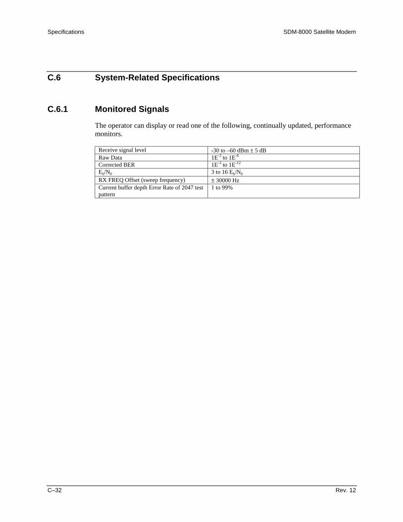
Specifications SDM-8000 Satellite Modem
C–32 Rev. 12
C.6 System-Related Specifications
C.6.1 Monitored Signals
The operator can display or read one of the following, continually updated, performancemonitors.
Receive signal level -30 to –60 dBm ± 5 dBRaw Data 1E-3 to 1E-6
Corrected BER 1E-3 to 1E-12
Eb/N0 3 to 16 Eb/N0
RX FREQ Offset (sweep frequency) ± 30000 HzCurrent buffer depth Error Rate of 2047 testpattern
1 to 99%
Comtech EFData is an ISO 9001 Registered Company
SDM-8000SDM-8000SDM-8000SDM-8000Satellite ModemSatellite ModemSatellite ModemSatellite ModemInstallation and Operation ManualInstallation and Operation ManualInstallation and Operation ManualInstallation and Operation ManualAddendum AAddendum AAddendum AAddendum A
Subject: Update Software Version to 21.1.1Part Number: MN/SDM8000.AACRevision 0 Addendum ANovember 11, 1999
Special Instructions:
This document contains new information for the SDM-8000 satellite modem installation and operationmanual, part number MN/SDM8000.IOM Rev. 2 dated November 7, 1995.
Notes:1. Insert this title page immediately after the manual title page to indicate that the manual was
updated with this addendum.2. To identify changes made to the previous edition, refer to the change bars located in the outside
margins. [or:] Change bars were not utilized.
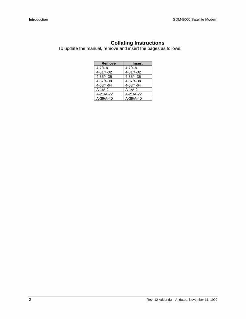
Introduction SDM-8000 Satellite Modem
2 Rev. 12 Addendum A, dated, November 11, 1999
Collating InstructionsTo update the manual, remove and insert the pages as follows:
Remove Insert4-7/4-8 4-7/4-84-31/4-32 4-31/4-324-35/4-36 4-35/4-364-37/4-38 4-37/4-384-63/4-64 4-63/4-64A-1/A-2 A-1/A-2A-21/A-22 A-21/A-22A-39/A-40 A-39/A-40
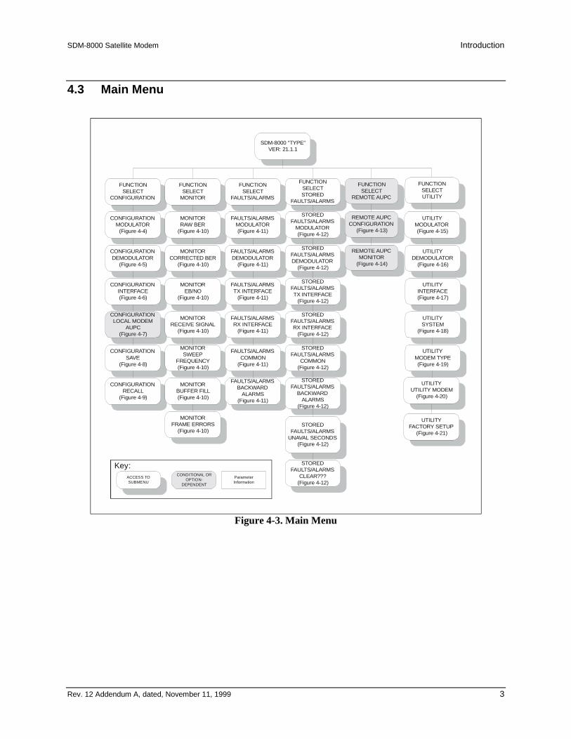
SDM-8000 Satellite Modem Introduction
Rev. 12 Addendum A, dated, November 11, 1999 3
4.3 Main Menu
SDM-8000 "TYPE"VER: 21.1.1
FUNCTIONSELECT
CONFIGURATION
FUNCTIONSELECT
MONITOR
FUNCTIONSELECT
FAULTS/ALARMS
CONFIGURATIONMODULATOR
(Figure 4-4)
CONFIGURATIONDEMODULATOR
(Figure 4-5)
CONFIGURATIONLOCAL MODEM
AUPC(Figure 4-7)
CONFIGURATIONINTERFACE(Figure 4-6)
CONFIGURATIONSAVE
(Figure 4-8)
MONITORRAW BER
(Figure 4-10)
MONITORCORRECTED BER
(Figure 4-10)
MONITOREB/NO
(Figure 4-10)
MONITORRECEIVE SIGNAL
(Figure 4-10)
MONITORSWEEP
FREQUENCY(Figure 4-10)
MONITORFRAME ERRORS
(Figure 4-10)
FAULTS/ALARMSMODULATOR(Figure 4-11)
FAULTS/ALARMSDEMODULATOR
(Figure 4-11)
FAULTS/ALARMSTX INTERFACE
(Figure 4-11)
FAULTS/ALARMSRX INTERFACE
(Figure 4-11)
FAULTS/ALARMSCOMMON
(Figure 4-11)
FUNCTIONSELECTSTORED
FAULTS/ALARMS
STOREDFAULTS/ALARMS
MODULATOR(Figure 4-12)
STOREDFAULTS/ALARMSDEMODULATOR
(Figure 4-12)
STOREDFAULTS/ALARMSTX INTERFACE
(Figure 4-12)
STOREDFAULTS/ALARMSRX INTERFACE
(Figure 4-12)
STOREDFAULTS/ALARMS
COMMON(Figure 4-12)
STOREDFAULTS/ALARMS
UNAVAL SECONDS(Figure 4-12)
STOREDFAULTS/ALARMS
CLEAR???(Figure 4-12)
UTILITYINTERFACE(Figure 4-17)
UTILITYSYSTEM
(Figure 4-18)
UTILITYMODEM TYPE(Figure 4-19)
UTILITYUTILITY MODEM
(Figure 4-20)
CONFIGURATIONRECALL
(Figure 4-9)
ACCESS TOSUBMENU
CONDITIONAL OROPTION-
DEPENDENT
ParameterInformation
Key:
FUNCTIONSELECT
REMOTE AUPC
REMOTE AUPCCONFIGURATION
(Figure 4-13)
REMOTE AUPCMONITOR
(Figure 4-14)
FUNCTIONSELECTUTILITY
UTILITYMODULATOR(Figure 4-15)
UTILITYDEMODULATOR
(Figure 4-16)
MONITORBUFFER FILL(Figure 4-10)
FAULTS/ALARMSBACKWARD
ALARMS(Figure 4-11)
STOREDFAULTS/ALARMS
BACKWARDALARMS
(Figure 4-12)
UTILITYFACTORY SETUP
(Figure 4-21)
Figure 4-3. Main Menu

Introduction SDM-8000 Satellite Modem
4 Rev. 12 Addendum A, dated, November 11, 1999
SDM-8000 "TYPE"VER: X.X.X
FUNCTION SELECTCONFIGURATION
CONFIGURATIONMODULATOR
TX-X CODE_RATE TX-IF FREQUENCY TX-IF OUTPUT TX POWER LEVEL
SCRAMBLER DIFF. ENCODER CARRIER MODE MODULATOR REF.
RS ENCODER
See Description Table.50 to 180 MHz
In 2.5 kHz steps.ONOFF -5 to -30 dBm (no offset)
-109.9 to +114.9 dBm (offset, fixed /user)
ONOFF
Not available for IBS orD&I overhead.
ONOFF
NORMAL (OFF)CENTER
DUALOFFSET
INTERNALEXT 5 MHzEXT 10 MHzEXT 20 MHz
Modulator Reference/External Divider Option
Only.
ONOFF
Reed-Solomon OptionOnly.
ACCESS TOSUBMENU
CONDITIONALOR OPTION-DEPENDENT
ParameterInformation
Key:SCT PLL REF
MODULATOR REFEXT-REF FREQ
Optional: With HighStability Modulator
Figure 4-4. Configuration Modulator Menu

SDM-8000 Satellite Modem Introduction
Rev. 12 Addendum A, dated, November 11, 1999 5
4.3.11 Monitor
Refer to 4-10.
When the Monitor level is entered, press [←] or [→] to select the desired monitorfunction. Each monitor function is displayed in real time as long as it is selected.
RAW BER Displays the current raw BER or ”No Data” (if carrier is not locked).Range: <m.m-e to >m.m-e. Note: Low limit is based on performance. High limit is based on data/code rate.
CORRECTEDBER
Displays the current corrected BER or ”No Data” (if carrier is not locked).Range: <m.m-e to >m.m-e. Note: Low limit is based on performance. Hi h limit is 1.0-12.
Eb/N0 Displays the current Eb/N0 or ”No Data” (if carrier is not locked).Range: <mm.m to >mm.m.Note: Low limit is based on the data rate. Hi limit is 16.0 dB.
RECEIVESIGNAL
Displays the current receive signal level.Range: -25.0 to -60.0 dBm.
SWEEPFREQUENCY
Displays the current sweep frequency or ”No Data” (if carrier is not locked).Range: -30 000 to+30 000 Hz.
BUFFER FILL Displays the current plesiochronous buffer fill status percent.Range: nn% (1% to 99%).Note: This menu is only available when buffer is installed.
FRAMEERRORS
Displays the current framing pattern bit error rate or ”No Data” (if carrier is notlocked). Monitors the currently selected READ ERROR function.Range: (mm.m-e to >mm.m- e.Note: Low limit is based an performance. High limit is based on the data/coderate. This menu is only available when DEMUX is installed.

Introduction SDM-8000 Satellite Modem
6 Rev. 12 Addendum A, dated, November 11, 1999
SDM-8000 "TYPE"VER: X.X.X
FUNCTION SELECTFAULTS/ALARMS
(see Notes)
MODULATOR DEMODULATOR TX INTERFACE RX INTERFACE
COMMON BACKWARD ALARMS
IF SYNTHESIZERDATA CLOCK ACTDATA CLOCK SYN
I CHANNELQ CHANNELAGC LEVEL
INTERNAL SCT SYNMODULE
EXT REF ACTPROGRAMMING
CONFIGURATION
CARRIER DETECTIF SYNTHESIZERRX CLOCK SYN
I CHANNELQ CHANNEL
DESCRAMBLERBER THRESHOLD
MODULEPROGRAMMING
CONFIGURATION
TX DROPTX DATA/AISTX CLK PLL
TX CLK ACTIVITYPROGRAMMING
CONFIGURATION
BUFFER UNDERFLOWBUFFER OVERFLOW
RX DATA/AISFRAME BER
BACKWARD ALARMBUFFER CLK PLLBUFFER CLK ACT
DEMUX LOCKRX 2047 LOCKBUFFER FULL
RX INSERTPROGRAMMING
CONFIGURATION
BATTERY/CLOCK-12 VOLT SUPPLY+12 VOLT SUPPLY+5 VOLT SUPPLY-5 VOLT SUPPLYCONTROLLER
INTERFACE MODULE
BW ALARM RX #4BW ALARM RX #3BW ALARM RX #2BW ALARM RX #1BW ALARM TX #4BW ALARM TX #3BW ALARM TX #2BW ALARM TX #1
IDR only.
Notes:
1. A “-” indicates that no fault oralarm exists.
2. A “+” indicates that a faultexists, and will cause switchingin a redundant system.
3. A reversed contrast “+”indicates an active alarm.
ACCESS TOSUBMENU
CONDITIONAL OROPTION-DEPENDENT Parameter Information
Key:
TX EXT DVB MUX
Figure 4-11. Faults/Alarms Menu
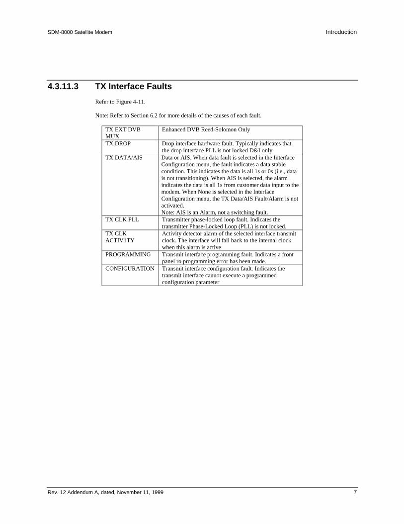
SDM-8000 Satellite Modem Introduction
Rev. 12 Addendum A, dated, November 11, 1999 7
4.3.11.3 TX Interface FaultsRefer to Figure 4-11.
Note: Refer to Section 6.2 for more details of the causes of each fault.
TX EXT DVBMUX
Enhanced DVB Reed-Solomon Only
TX DROP Drop interface hardware fault. Typically indicates thatthe drop interface PLL is not locked D&I only
TX DATA/AIS Data or AIS. When data fault is selected in the InterfaceConfiguration menu, the fault indicates a data stablecondition. This indicates the data is all 1s or 0s (i.e., datais not transitioning). When AIS is selected, the alarmindicates the data is all 1s from customer data input to themodem. When None is selected in the InterfaceConfiguration menu, the TX Data/AIS Fault/Alarm is notactivated.Note: AIS is an Alarm, not a switching fault.
TX CLK PLL Transmitter phase-locked loop fault. Indicates thetransmitter Phase-Locked Loop (PLL) is not locked.
TX CLKACTIV1TY
Activity detector alarm of the selected interface transmitclock. The interface will fall back to the internal clockwhen this alarm is active
PROGRAMMING Transmit interface programming fault. Indicates a frontpanel ro programming error has been made.
CONFIGURATION Transmit interface configuration fault. Indicates thetransmit interface cannot execute a programmedconfiguration parameter
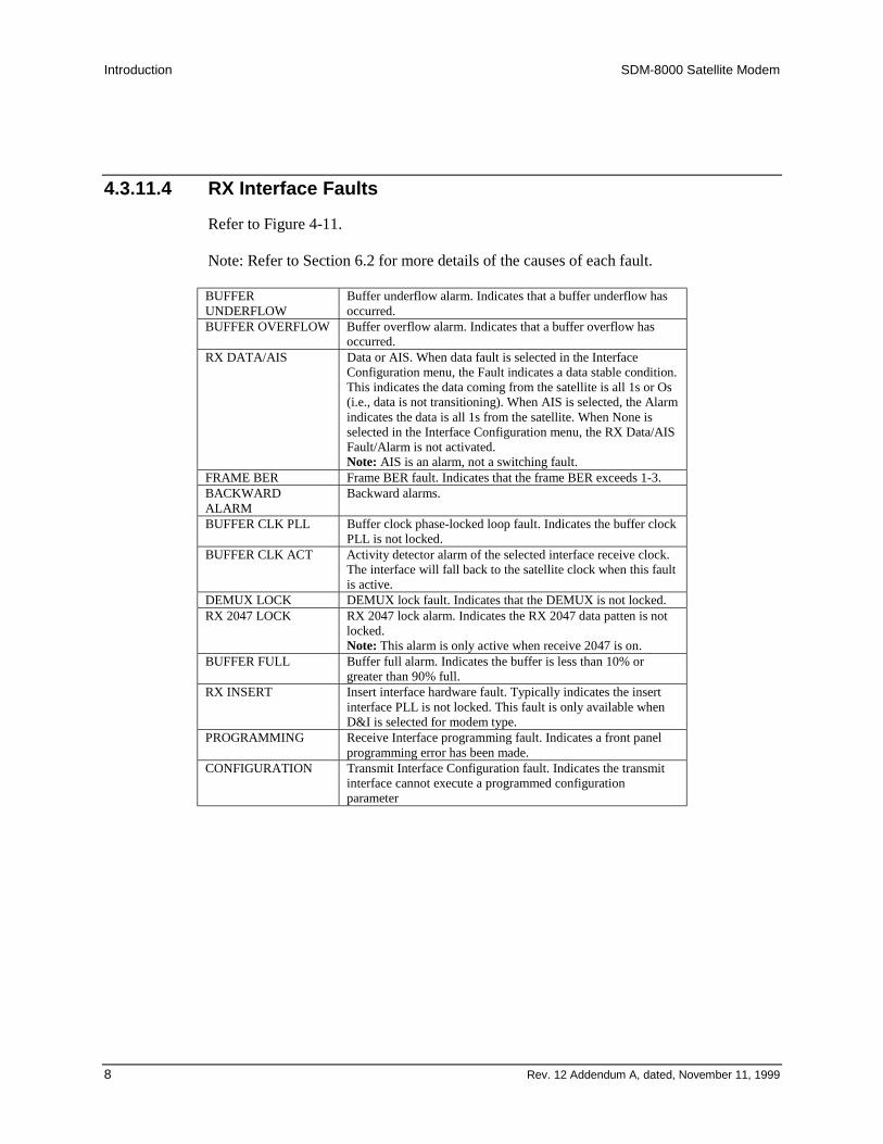
Introduction SDM-8000 Satellite Modem
8 Rev. 12 Addendum A, dated, November 11, 1999
4.3.11.4 RX Interface Faults
Refer to Figure 4-11.
Note: Refer to Section 6.2 for more details of the causes of each fault.
BUFFERUNDERFLOW
Buffer underflow alarm. Indicates that a buffer underflow hasoccurred.
BUFFER OVERFLOW Buffer overflow alarm. Indicates that a buffer overflow hasoccurred.
RX DATA/AIS Data or AIS. When data fault is selected in the InterfaceConfiguration menu, the Fault indicates a data stable condition.This indicates the data coming from the satellite is all 1s or Os(i.e., data is not transitioning). When AIS is selected, the Alarmindicates the data is all 1s from the satellite. When None isselected in the Interface Configuration menu, the RX Data/AISFault/Alarm is not activated.Note: AIS is an alarm, not a switching fault.
FRAME BER Frame BER fault. Indicates that the frame BER exceeds 1-3.BACKWARDALARM
Backward alarms.
BUFFER CLK PLL Buffer clock phase-locked loop fault. Indicates the buffer clockPLL is not locked.
BUFFER CLK ACT Activity detector alarm of the selected interface receive clock.The interface will fall back to the satellite clock when this faultis active.
DEMUX LOCK DEMUX lock fault. Indicates that the DEMUX is not locked.RX 2047 LOCK RX 2047 lock alarm. Indicates the RX 2047 data patten is not
locked.Note: This alarm is only active when receive 2047 is on.
BUFFER FULL Buffer full alarm. Indicates the buffer is less than 10% orgreater than 90% full.
RX INSERT Insert interface hardware fault. Typically indicates the insertinterface PLL is not locked. This fault is only available whenD&I is selected for modem type.
PROGRAMMING Receive Interface programming fault. Indicates a front panelprogramming error has been made.
CONFIGURATION Transmit Interface Configuration fault. Indicates the transmitinterface cannot execute a programmed configurationparameter
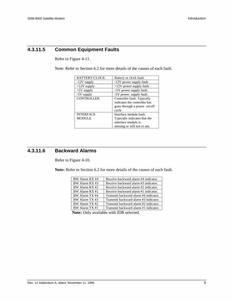
SDM-8000 Satellite Modem Introduction
Rev. 12 Addendum A, dated, November 11, 1999 9
4.3.11.5 Common Equipment Faults
Refer to Figure 4-11.
Note: Refer to Section 6.2 for more details of the causes of each fault.
BATTERY/CLOCK Battery or clock fault.-12V supply -12V power supply fault+12V supply +12V power supply fault.+5V supply +5V power supply fault.-5V supply -5V power supply fault.CONTROLLER Controller fault. Typically
indicates the controller hasgone through a power on/offcycle
INTERFACEMODULE
Interface module fault.Typically indicates that theinterface module ismissing or will not ro am.
4.3.11.6 Backward Alarms
Refer to Figure 4-10.
Note: Refer to Section 6.2 for more details of the causes of each fault.
BW Alarm RX #4 Receive backward alarm #4 indicator.BW Alarm RX #3 Receive backward alarm #3 indicator.BW Alarm RX #2 Receive backward alarm #2 indicator.BW Alarm RX #1 Receive backward alarm #1 indicator.BW Alarm TX #4 Transmit backward alarm #4 indicator.BW Alarm TX #3 Transmit backward alarm #3 indicator.BW Alarm TX #2 Transmit backward alarm #2 indicator.BW Alarm TX #1 Transmit backward alarm #1 indicator.
Note: Only available with IDR selected.
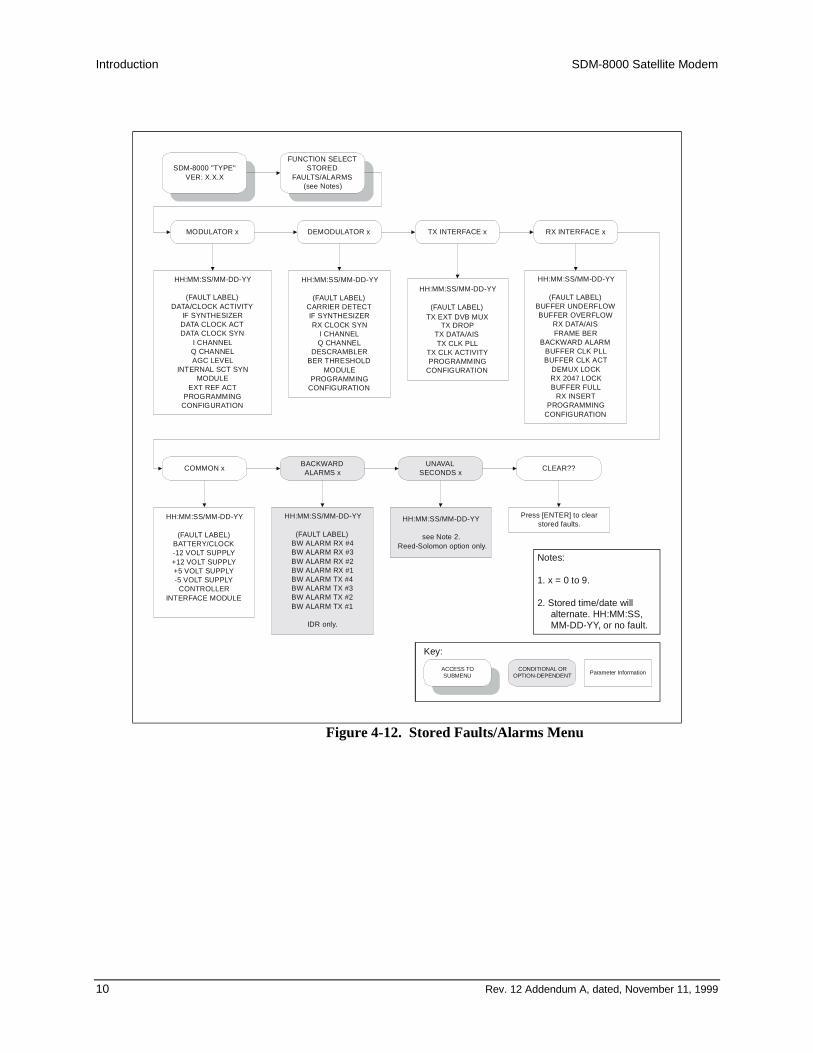
Introduction SDM-8000 Satellite Modem
10 Rev. 12 Addendum A, dated, November 11, 1999
SDM-8000 "TYPE"VER: X.X.X
FUNCTION SELECTSTORED
FAULTS/ALARMS(see Notes)
MODULATOR x DEMODULATOR x TX INTERFACE x RX INTERFACE x
COMMON x BACKWARDALARMS x
HH:MM:SS/MM-DD-YY
(FAULT LABEL)DATA/CLOCK ACTIVITY
IF SYNTHESIZERDATA CLOCK ACTDATA CLOCK SYN
I CHANNELQ CHANNELAGC LEVEL
INTERNAL SCT SYNMODULE
EXT REF ACTPROGRAMMING
CONFIGURATION
HH:MM:SS/MM-DD-YY
(FAULT LABEL)CARRIER DETECTIF SYNTHESIZERRX CLOCK SYN
I CHANNELQ CHANNEL
DESCRAMBLERBER THRESHOLD
MODULEPROGRAMMING
CONFIGURATION
HH:MM:SS/MM-DD-YY
(FAULT LABEL)
TX DROPTX DATA/AISTX CLK PLL
TX CLK ACTIVITYPROGRAMMING
CONFIGURATION
HH:MM:SS/MM-DD-YY
(FAULT LABEL)BUFFER UNDERFLOWBUFFER OVERFLOW
RX DATA/AISFRAME BER
BACKWARD ALARMBUFFER CLK PLLBUFFER CLK ACT
DEMUX LOCKRX 2047 LOCKBUFFER FULL
RX INSERTPROGRAMMING
CONFIGURATION
HH:MM:SS/MM-DD-YY
(FAULT LABEL)BATTERY/CLOCK-12 VOLT SUPPLY+12 VOLT SUPPLY+5 VOLT SUPPLY-5 VOLT SUPPLY
CONTROLLERINTERFACE MODULE
HH:MM:SS/MM-DD-YY
(FAULT LABEL)BW ALARM RX #4BW ALARM RX #3BW ALARM RX #2BW ALARM RX #1BW ALARM TX #4BW ALARM TX #3BW ALARM TX #2BW ALARM TX #1
IDR only.
Notes:
1. x = 0 to 9.
2. Stored time/date willalternate. HH:MM:SS,MM-DD-YY, or no fault.
UNAVALSECONDS x
HH:MM:SS/MM-DD-YY
see Note 2.Reed-Solomon option only.
CLEAR??
Press [ENTER] to clearstored faults.
ACCESS TOSUBMENU
CONDITIONAL OROPTION-DEPENDENT Parameter Information
Key:
TX EXT DVB MUX
Figure 4-12. Stored Faults/Alarms Menu

SDM-8000 Satellite Modem Introduction
Rev. 12 Addendum A, dated, November 11, 1999 11
SDM-8000 "TYPE"VER:X.X.X
FUNCTION SELECTUTILITY
UTILITYFACTORY SETUP
UTILITY FACTORYSETUP
Factory Settings Only.
ACCESS TOSUBMENU
CONDITIONAL OROPTION-DEPENDENT
PARAMETERINFORMATION
Key:
Figure 4-20. Utility Factory Setup Menu
4.3.11.8 Factory Utility Setup
Refer to Figure 4-20.
This configuration is used for factory alignment. Factory setup should not be changed byunauthorized persons. To do so may cause modem failure.
The following lists the factory set parameters:
• TX filter setup o RX filter setup• TX course power table• TX fine power table• RX signal level setup• MOD faults enable• DEMOD faults enable• TX interface faults enable• RX interface faults enable• MOD module reset• DEMOD module reset• Interface module reset

Introduction SDM-8000 Satellite Modem
12 Rev. 12 Addendum A, dated, November 11, 1999
CUSTOMERDATA
IBS or IDRINTERFACE
ENCODER/MODULATOR
TRANSMIT RFEQUIPMENT
ANT
AC POWERPOWERMICRO-COMPUTER
REMOTE SERIALINTERFACE
FAULT INDICATORSSUPPLY
RECEIVE RFEQUIPMENT
DEMODULATOR/DECODER
SDM-8000SATELLITE MODEM
LOOPBACK CHANGES DEMODRECEIVE FREQUENCY TO70 MHz WITHOUT LOSINGORIGINAL PROGRAMMINGINFORMATION.
RF LBK = 70 MHz
RX = 73 MHz
Figure 4-21. RF Loopback
Note: When RF loopback is turned on, the demodulator receive frequency is programmed to be the samefrequency as the modulator transmit frequency. This test mode allows the user to verify the satellite linkwithout changing the programmed frequency of the demodulator. When RF loopback is turned off, thedemodulator is programmed back to the previous frequency.

SDM-8000 Satellite Modem Introduction
Rev. 12 Addendum A, dated, November 11, 1999 13
Appendix AREMOTE CONTROL OPERATION
This appendix describes the remote control operation of the SDM-8000.
• Firmware number: FW/2448-1AE• Software version: 21.1.1
A.1 GeneralRemote controls and status information are transferred via an EIA-485 (optional EIA-232) serial communications link.
Commands and data are transferred on the remote control communications link as USASCII-encoded character strings. The remote communications link is operated in a half-duplex mode.
Communications on the remote link are initiated by a remote controller or terminal. Themodem never transmits data on the link unless it is commanded to do so.
A.2 Message Structure
The ASCII character format used requires 11 bits/character:
• 1 start bit• Information bits (Select one)• 7 information bits• 8 information bits 1 parity bit (Used with 7 information bits) 2 stop bits
Messages on the remote link fall into the categories of commands and responses.Commands are messages which are transmitted to a satellite modem, while responses aremessages returned by a satellite modem in response to a command.
The general message structure is as follows:
• Start Character• Device Address• Command/Response• End of Message Character
A.2.1 Start Character
A single character precedes all messages transmitted on the remote link. This characterflags the start of a message. This character is:
• ”<” for commands• ”>” for responses
Introduction SDM-8000 Satellite Modem
14 Rev. 12 Addendum A, dated, November 11, 1999
A.2.2 Device Address
The device address is the address of the one satellite modem which is designated toreceive a transmitted command, or which is responding to a command.
Valid device addresses are 1 to 3 characters long, and in the range of 1 to 255. Address 0is reserved as a global address which simultaneously addresses all devices on a givencommunications link. Devices do not acknowledge global commands.
Each satellite modem which is connected to a common remote communications link mustbe assigned its own unique address. Addresses are software selectable at the modem, andmust be in the range of 1 to 255.

SDM-8000 Satellite Modem Introduction
Rev. 12 Addendum A, dated, November 11, 1999 15
A.4.1 Configuration
Modulator/CoderConfigProgramStatus
Command:Response:
<add/MCP_'cr'>add/MCP_'cr'SMT_xxxxxx'cr'ITOT_xxxx'cr'MOM_xxxxxxx'cr'MT_xxxx'cr'MET_xxx'cr'MF_nnn.nnnn'cr'MR_nnnnn_mmmm.mmm'cr'MPO_snn.n'cr'LPC_xxx'cr' (Note 1)MOP_snn.n'cr' (Note 2)SE_xxx'cr'DENC_xxx'cr'ERF_nnnnn.n'cr'TC_xxx'cr'TCP_xxxx'cr'BBL_xxx'cr'ILB_xxx'cr'ILT_xxx'cr'ICFT_xxxx'cr'ISP_xxx'cr'TDF_xxxx'cr'ISCL_TX1_nnn'cr'ISCL_TX2_nnn'cr'TDP_xxxx'cr'DDF_xxxxxx'cr' (Note 3)BDCA_dd;cc_dd;cc...'cr' (Note 3)MRC_xxx'cr'MSR_xxx'cr'RSEN_xxx'cr'BW_TX1_nnn'cr' (Note 4)BW_TX2_nnn'cr' (Note 4)BW_TX3_nnn'cr' (Note 4)BW_TX4_nnn'cr' (Note 4)TXDR_xxxxxx'cr'TOBR_nnnnn'cr' (Note 5)TCCL_n'cr' (Note 5)TCSB_n'cr' (Note 5)TOCP_xxxx'cr' (Note 5)TCT_xxxxxxxx'cr' (Note 5)NOMP_snn.n'cr' (Note 5)MINP_snn.n'cr' (Note 5)MAXP_snn.n'cr' (Note 5)LCL_xxxx'cr' (Note 5)RCL_xxxx'cr' (Note 5)TDVB_xxxx'cr' (Note 6)T310_xxx'cr'MSPR_xxx'cr'RF_xxx'cr''lf']
System Modem TypeInterface Transmit Overhead TypeModem Operation ModeModulator TypeModulator Encoder TypeModulator FrequencyModulator RateModulator Power OffsetAUPC Local Power EnableModulator Output PowerScrambler Enable (ON/OFF)Differential Encoder (ON/OFF)External Reference FrequencyTransmit Clock (Source)Transmit Clock PhaseBaseband LoopbackInterface LoopbackInterface Loop TimingInterface Coding Format TransmitInterface Substitution Pattern (TX 2047)Transmit Data FaultService Channel Level TX1Service Channel Level TX2Transmit Data PhaseDrop Data FormatBulk Drop Channels AssignmentModulator Reference ClockModulator Spectrum RotationReed-Solomon Encoder (ON/OFF)Backward Alarm Enable TX1Backward Alarm Enable TX2Backward Alarm Enable TX3Backward Alarm Enable TX4TX Driver TypeASYNC TX Overhead Baud RateASYNC TX Channel Character LengthASYNC TX Channel Stop BitsASYNC TX Overhead Channel ParityASYNC TX Communications TypeAUPC Nominal Power ValueAUPC Minimum Power ValueAUPC Maximum Power ValueAUPC Local Carrier LossAUPC Remote Carrier LossTransmit DVB FramingTX 8PSK 2/3 IESS-310 OperationModulator SCT PLL ReferenceRF Output (ON/OFF)
This command is used by the EFData M:N protection switch tocollect information that is necessary to configure back-upmodems. Because this command (content and/or order) canbe changed at any time by EFData, it is advisable that othercommands ('MCS_' and 'ICS_', or 'BCS_') be used for M&Csystems.
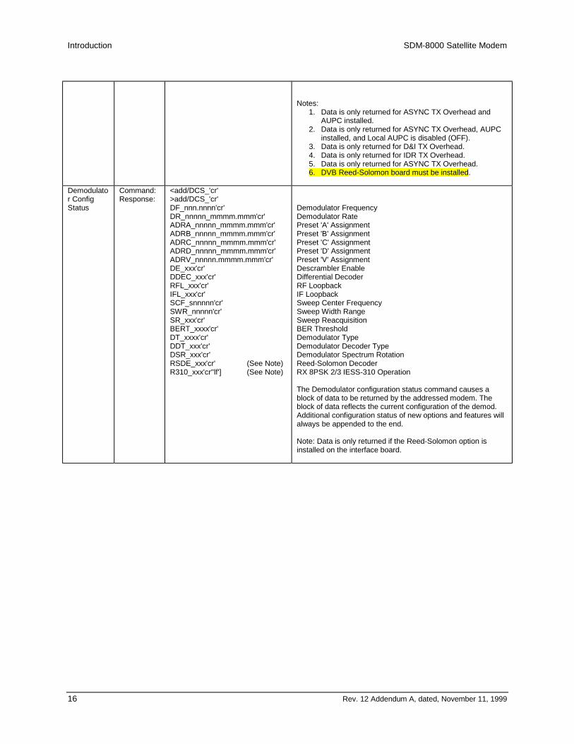
Introduction SDM-8000 Satellite Modem
16 Rev. 12 Addendum A, dated, November 11, 1999
Notes:1. Data is only returned for ASYNC TX Overhead and
AUPC installed.2. Data is only returned for ASYNC TX Overhead, AUPC
installed, and Local AUPC is disabled (OFF).3. Data is only returned for D&I TX Overhead.4. Data is only returned for IDR TX Overhead.5. Data is only returned for ASYNC TX Overhead.6. DVB Reed-Solomon board must be installed.
Demodulator ConfigStatus
Command:Response:
<add/DCS_'cr'>add/DCS_'cr'DF_nnn.nnnn'cr'DR_nnnnn_mmmm.mmm'cr'ADRA_nnnnn_mmmm.mmm'cr'ADRB_nnnnn_mmmm.mmm'cr'ADRC_nnnnn_mmmm.mmm'cr'ADRD_nnnnn_mmmm.mmm'cr'ADRV_nnnnn.mmmm.mmm'cr'DE_xxx'cr'DDEC_xxx'cr'RFL_xxx'cr'IFL_xxx'cr'SCF_snnnnn'cr'SWR_nnnnn'cr'SR_xxx'cr'BERT_xxxx'cr'DT_xxxx'cr'DDT_xxx'cr'DSR_xxx'cr'RSDE_xxx'cr' (See Note)R310_xxx'cr''lf'] (See Note)
Demodulator FrequencyDemodulator RatePreset 'A' AssignmentPreset 'B' AssignmentPreset 'C' AssignmentPreset 'D' AssignmentPreset 'V' AssignmentDescrambler EnableDifferential DecoderRF LoopbackIF LoopbackSweep Center FrequencySweep Width RangeSweep ReacquisitionBER ThresholdDemodulator TypeDemodulator Decoder TypeDemodulator Spectrum RotationReed-Solomon DecoderRX 8PSK 2/3 IESS-310 Operation
The Demodulator configuration status command causes ablock of data to be returned by the addressed modem. Theblock of data reflects the current configuration of the demod.Additional configuration status of new options and features willalways be appended to the end.
Note: Data is only returned if the Reed-Solomon option isinstalled on the interface board.
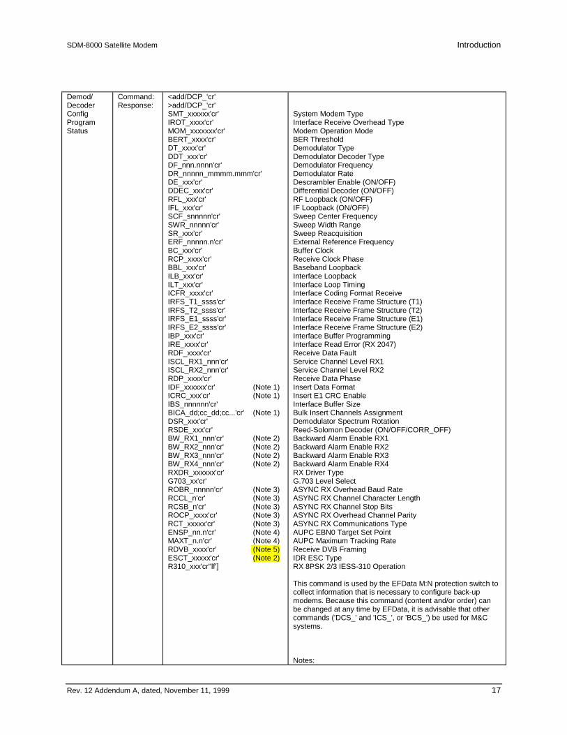
SDM-8000 Satellite Modem Introduction
Rev. 12 Addendum A, dated, November 11, 1999 17
Demod/DecoderConfigProgramStatus
Command:Response:
<add/DCP_'cr'>add/DCP_'cr'SMT_xxxxxx'cr'IROT_xxxx'cr'MOM_xxxxxxx'cr'BERT_xxxx'cr'DT_xxxx'cr'DDT_xxx'cr'DF_nnn.nnnn'cr'DR_nnnnn_mmmm.mmm'cr'DE_xxx'cr'DDEC_xxx'cr'RFL_xxx'cr'IFL_xxx'cr'SCF_snnnnn'cr'SWR_nnnnn'cr'SR_xxx'cr'ERF_nnnnn.n'cr'BC_xxx'cr'RCP_xxxx'cr'BBL_xxx'cr'ILB_xxx'cr'ILT_xxx'cr'ICFR_xxxx'cr'IRFS_T1_ssss'cr'IRFS_T2_ssss'cr'IRFS_E1_ssss'cr'IRFS_E2_ssss'cr'IBP_xxx'cr'IRE_xxxx'cr'RDF_xxxx'cr'ISCL_RX1_nnn'cr'ISCL_RX2_nnn'cr'RDP_xxxx'cr'IDF_xxxxxx'cr' (Note 1)ICRC_xxx'cr' (Note 1)IBS_nnnnnn'cr'BICA_dd;cc_dd;cc...'cr' (Note 1)DSR_xxx'cr'RSDE_xxx'cr'BW_RX1_nnn'cr' (Note 2)BW_RX2_nnn'cr' (Note 2)BW_RX3_nnn'cr' (Note 2)BW_RX4_nnn'cr' (Note 2)RXDR_xxxxxx'cr'G703_xx'cr'ROBR_nnnnn'cr' (Note 3)RCCL_n'cr' (Note 3)RCSB_n'cr' (Note 3)ROCP_xxxx'cr' (Note 3)RCT_xxxxx'cr' (Note 3)ENSP_nn.n'cr' (Note 4)MAXT_n.n'cr' (Note 4)RDVB_xxxx'cr' (Note 5)ESCT_xxxxx'cr' (Note 2)R310_xxx'cr''lf']
System Modem TypeInterface Receive Overhead TypeModem Operation ModeBER ThresholdDemodulator TypeDemodulator Decoder TypeDemodulator FrequencyDemodulator RateDescrambler Enable (ON/OFF)Differential Decoder (ON/OFF)RF Loopback (ON/OFF)IF Loopback (ON/OFF)Sweep Center FrequencySweep Width RangeSweep ReacquisitionExternal Reference FrequencyBuffer ClockReceive Clock PhaseBaseband LoopbackInterface LoopbackInterface Loop TimingInterface Coding Format ReceiveInterface Receive Frame Structure (T1)Interface Receive Frame Structure (T2)Interface Receive Frame Structure (E1)Interface Receive Frame Structure (E2)Interface Buffer ProgrammingInterface Read Error (RX 2047)Receive Data FaultService Channel Level RX1Service Channel Level RX2Receive Data PhaseInsert Data FormatInsert E1 CRC EnableInterface Buffer SizeBulk Insert Channels AssignmentDemodulator Spectrum RotationReed-Solomon Decoder (ON/OFF/CORR_OFF)Backward Alarm Enable RX1Backward Alarm Enable RX2Backward Alarm Enable RX3Backward Alarm Enable RX4RX Driver TypeG.703 Level SelectASYNC RX Overhead Baud RateASYNC RX Channel Character LengthASYNC RX Channel Stop BitsASYNC RX Overhead Channel ParityASYNC RX Communications TypeAUPC EBN0 Target Set PointAUPC Maximum Tracking RateReceive DVB FramingIDR ESC TypeRX 8PSK 2/3 IESS-310 Operation
This command is used by the EFData M:N protection switch tocollect information that is necessary to configure back-upmodems. Because this command (content and/or order) canbe changed at any time by EFData, it is advisable that othercommands ('DCS_' and 'ICS_', or 'BCS_') be used for M&Csystems.
Notes:

Introduction SDM-8000 Satellite Modem
18 Rev. 12 Addendum A, dated, November 11, 1999
1. Data is only returned for D&I RX Overhead.2. Data is only returned for IDR RX Overhead.3. Data is only returned for ASYNC RX Overhead.4. Data is only returned for ASYNC RX Overhead and
AUPC installed.5. DVB Reed-Solomon board must be installed.
InterfaceConfigStatus
Command:Response:
<add/ICS_'cr'>add/ICS_'cr'TC_xxx'cr'ERF_nnnnn.n'cr'TCP_xxxx'cr'RCP_xxxx'cr'BBL_xxx'cr'ILB_xxx'cr'ILT_xxx'cr'ICFT_xxxx'cr'ICFR_xxxx'cr'BC_xxx'cr'IRFS_T1_ssss'cr'IRFS_T2_ssss'cr'IRFS_E1_ssss'cr'IRFS_E2_ssss'cr'IBP_xxx'cr'IBS_nnnnnn'cr'ITOT_xxxx'cr'IROT_xxxx'cr'ISP_xxx'cr'IRE_xxxx'cr'TDF_xxxx'cr'RDF_xxxx'cr'ISCL_TX1_nnn'cr'ISCL_TX2_nnn'cr'ISCL_RX1_nnn'cr'ISCL_RX2_nnn'cr'TDP_xxxx'cr'RDP_xxxx'cr'DDF_xxxxxx'cr' (Note 1)BDCA_dd;cc_dd;cc...'cr' (Note 1)ICRC_xxx'cr' (Note 2)IDF_xxxxxx'cr' (Note 2)BICA_dd;cc_dd;cc...'cr' (Note 2)BW_TX1_nnn'cr' (Note 3)BW_TX2_nnn'cr' (Note 3)BW_TX3_nnn'cr' (Note 3)BW_TX4_nnn'cr' (Note 3)BW_RX1_nnn'cr' (Note 4)BW_RX2_nnn'cr' (Note 4)BW_RX3_nnn'cr' (Note 4)BW_RX4_nnn'cr' (Note 4)TXDR_xxxxxx'cr' (Note 5)RXDR_xxxxxx'cr' (Note 5)G703_xx'cr' (Note 5)TOBR_nnnnn'cr' (Note 6)TCCL_n'cr' (Note 6)TCSB_n'cr' (Note 6)TOCP_xxxx'cr' (Note 6)TCT_xxxxxxxx'cr' (Note 6)ROBR_nnnnn'cr' (Note 7)RCCL_n'cr' (Note 7)RCSB_n'cr' (Note 7)ROCP_xxxx'cr' (Note 7)RCT_xxxxx'cr' (Note 7)LPC_xxx'cr' (Note 8)NOMP_snn.n'cr' (Note 8)MINP_snn.n'cr' (Note 8)MAXP_snn.n'cr' (Note 8)LCL_xxxx'cr' (Note 8)
Transmit Clock (Source)External Reference FrequencyTransmit Clock PhaseReceive Clock PhaseBaseband LoopbackInterface LoopbackInterface Loop TimingInterface Coding Format TransmitInterface Coding Format ReceiveBuffer Clock (Source)Interface Receive Frame Structure (T1)Interface Receive Frame Structure (T2)Interface Receive Frame Structure (E1)Interface Receive Frame Structure (E2)Interface Buffer ProgrammingInterface Buffer SizeInterface Transmit Overhead TypeInterface Receive Overhead TypeInterface Substitution Pattern (TX 2047)Interface Read Error (RX 2047)Transmit Data FaultReceive Data FaultService Channel Level TX1Service Channel Level TX2Service Channel Level RX1Service Channel Level RX2Transmit Data PhaseReceive Data PhaseDrop Data FormatBulk Drop Channels AssignmentInsert E1 CRC EnableInsert Data FormatBulk Insert Channels AssignmentBackward Alarm Enable TX1Backward Alarm Enable TX2Backward Alarm Enable TX3Backward Alarm Enable TX4Backward Alarm Enable RX1Backward Alarm Enable RX2Backward Alarm Enable RX3Backward Alarm Enable RX4TX Driver TypeRX Driver TypeG.703 Level SelectASYNC Transmit Overhead Baud RateASYNC Transmit Channel Character LengthASYNC Transmit Channel Stop BitsASYNC Transmit Overhead Channel ParityASYNC Transmit Communications TypeASYNC Receive Overhead Baud RateASYNC Receive Channel Character LengthASYNC Receive Channel Stop BitsASYNC Receive Overhead Channel ParityASYNC Receive Communications TypeAUPC Local Power EnableAUPC Nominal Power ValueAUPC Minimum Power ValueAUPC Maximum Power ValueAUPC Local Carrier Loss
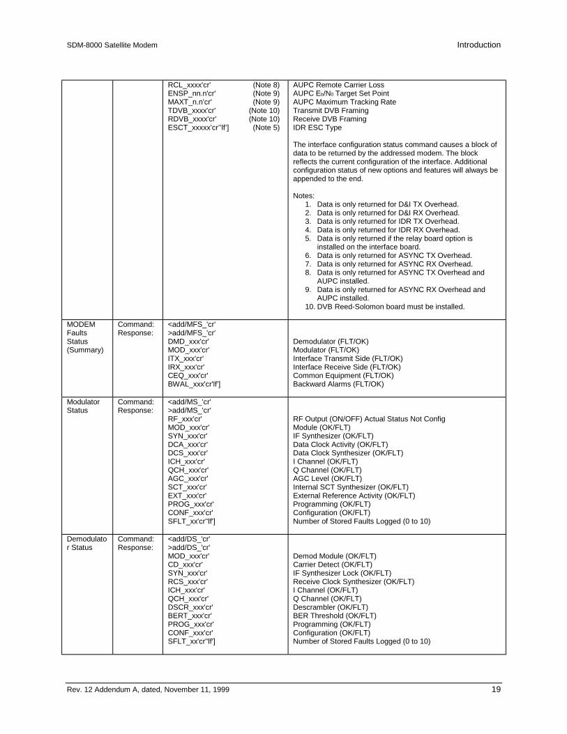
SDM-8000 Satellite Modem Introduction
Rev. 12 Addendum A, dated, November 11, 1999 19
RCL_xxxx'cr' (Note 8)ENSP_nn.n'cr' (Note 9)MAXT_n.n'cr' (Note 9)TDVB_xxxx'cr' (Note 10)RDVB_xxxx'cr' (Note 10)ESCT_xxxxx’cr’’lf’] (Note 5)
AUPC Remote Carrier LossAUPC Eb/N0 Target Set PointAUPC Maximum Tracking RateTransmit DVB FramingReceive DVB FramingIDR ESC Type
The interface configuration status command causes a block ofdata to be returned by the addressed modem. The blockreflects the current configuration of the interface. Additionalconfiguration status of new options and features will always beappended to the end.
Notes:1. Data is only returned for D&I TX Overhead.2. Data is only returned for D&I RX Overhead.3. Data is only returned for IDR TX Overhead.4. Data is only returned for IDR RX Overhead.5. Data is only returned if the relay board option is
installed on the interface board.6. Data is only returned for ASYNC TX Overhead.7. Data is only returned for ASYNC RX Overhead.8. Data is only returned for ASYNC TX Overhead and
AUPC installed.9. Data is only returned for ASYNC RX Overhead and
AUPC installed.10. DVB Reed-Solomon board must be installed.
MODEMFaultsStatus(Summary)
Command:Response:
<add/MFS_'cr'>add/MFS_'cr'DMD_xxx'cr'MOD_xxx'cr'ITX_xxx'cr'IRX_xxx'cr'CEQ_xxx'cr'BWAL_xxx'cr'lf']
Demodulator (FLT/OK)Modulator (FLT/OK)Interface Transmit Side (FLT/OK)Interface Receive Side (FLT/OK)Common Equipment (FLT/OK)Backward Alarms (FLT/OK)
ModulatorStatus
Command:Response:
<add/MS_'cr'>add/MS_'cr'RF_xxx'cr'MOD_xxx'cr'SYN_xxx'cr'DCA_xxx'cr'DCS_xxx'cr'ICH_xxx'cr'QCH_xxx'cr'AGC_xxx'cr'SCT_xxx'cr'EXT_xxx'cr'PROG_xxx'cr'CONF_xxx'cr'SFLT_xx'cr''lf']
RF Output (ON/OFF) Actual Status Not ConfigModule (OK/FLT)IF Synthesizer (OK/FLT)Data Clock Activity (OK/FLT)Data Clock Synthesizer (OK/FLT)I Channel (OK/FLT)Q Channel (OK/FLT)AGC Level (OK/FLT)Internal SCT Synthesizer (OK/FLT)External Reference Activity (OK/FLT)Programming (OK/FLT)Configuration (OK/FLT)Number of Stored Faults Logged (0 to 10)
Demodulator Status
Command:Response:
<add/DS_'cr'>add/DS_'cr'MOD_xxx'cr'CD_xxx'cr'SYN_xxx'cr'RCS_xxx'cr'ICH_xxx'cr'QCH_xxx'cr'DSCR_xxx'cr'BERT_xxx'cr'PROG_xxx'cr'CONF_xxx'cr'SFLT_xx'cr''lf']
Demod Module (OK/FLT)Carrier Detect (OK/FLT)IF Synthesizer Lock (OK/FLT)Receive Clock Synthesizer (OK/FLT)I Channel (OK/FLT)Q Channel (OK/FLT)Descrambler (OK/FLT)BER Threshold (OK/FLT)Programming (OK/FLT)Configuration (OK/FLT)Number of Stored Faults Logged (0 to 10)

Introduction SDM-8000 Satellite Modem
20 Rev. 12 Addendum A, dated, November 11, 1999
Reference page 46-47ChangeStatus
Command:Response:
<add/CS_'cr'>add/CS_x'cr''lf']
Where: The 'x' character is defined as follows:
'at' = no change since last BCS_ and BCSF_ polls.
'A' = BCS_ response has changed since last BCS_ poll
'B' = BCSF_ response has changed since last BCSF_poll
'C' = Both responses have changed since last BCS_ andBCSF_ polls.
This command indicates that a change has or has notoccurred on either the BCS_ or the BCSF_ response sincethe last BCS_ or BCSF_ poll.
EquipmentType
Command:Response:
<add/ET_'cr'>add/ET_tttttttt_xxx.yyy.zzz'cr''lf']
Where:tttttttt = Equipment type.xxx.yyy.zzz = Software version.
This command returns the equipment type and the softwareversion of the addressed device.
Monitor &ControlFirmwareInformation
Command:Response:
<add/MCFI_'cr'>add/MCFI_'cr'VER_xxx.yyy.zzz'cr'FW/nnnnnn-ddr'cr'mm/dd/yy'cr''lf']
Where:
xxx.yyy.zzz = Software version number (0.0.0 to999.999.999).
nnnnnn = Firmware number (0 to 999999).
dd = Firmware dash number (0 to 99).
r = Firmware revision (-, or A to Z).
ModulatorFirmwareInformation
Command:Response:
<add/MFI_'cr'>add/MFI_'cr'VER_xxx.yyy.zzz'cr'FW/nnnnnn-ddrr'cr'mm/dd/yy'cr'FPGA_FW/nnnnnn-ddrr'cr'FPGA_mm/dd/yy'cr''lf']
Where:
xxx.yyy.zzz = Software version number (0.0.0 to999.999.999).
nnnnnn = Firmware number (0 to 999999).
dd = Firmware dash number (0 to 99).
rr = Firmware revision (-, or A to Z).
Demodulator FirmwareInformation
Command:Response:
<add/DFI_'cr'>add/DFI_'cr'VER_xxx.yyy.zzz'cr'FW/nnnnnn-ddrr'cr'mm/dd/yy'cr'FPGA_FW/nnnnnn-ddrr'cr'FPGA_mm/dd/yy'cr''lf']
Where:
xxx.yyy.zzz = Software version number (0.0.0 to999.999.999).
nnnnnn = Firmware number (0 to 999999).
dd = Firmware dash number (0 to 99).
rr = Firmware revision (-, or A to Z).

SDM-8000 Satellite Modem Introduction
Rev. 12 Addendum A, dated, November 11, 1999 21
InterfaceFirmwareInformation
Command:Response:
<add/IFI_'cr'>add/IFI_'cr'VER_xxx.yyy.zzz'cr'FW/nnnnnn-ddrr'cr'mm/dd/yy'cr'FPGA_FW/nnnnnn-ddrr'cr'FPGA_mm/dd/yy'cr''lf']
Where:
xxx.yyy.zzz = Software version number (0.0.0 to999.999.999).
nnnnnn = Firmware number (0 to 999999).
dd = Firmware dash number (0 to 99).
rr = Firmware revision (-, or A to Z).
ModemTypeCompatibility Status
Command:Response:
<add/MTCS_tttttt'cr'>add/MTCS_tttttt'cr's,INT_MODULE'cr's,TX_TERR_INT'cr's,RX_TERR_INT'cr's,MUX'cr's,DEMUX'cr's,BUFFER'cr's,IDR_TX_BWA'cr's,IDR_TX_ESC'cr's,IDR_RX_BWA'cr's,IDR_RX_ESC'cr's,IDR AUDIO'cr's,IBS_ESC'cr's,MOD_TYPE'cr's,DEMOD_TYPE'cr's,ENCODER_TYPE'cr's,DECODER_TYPE'cr''lf']
Where:
tttttt = IDR, DI, ASYNC, DVB, CUSTOM, or TYPE n(modem type compatibility status desired).
n = 1 to 5s = 0, 1, x, X, or * (function requirement status)
s = 0 (Required function is not supported),1 (Required function is supported),x (Non required function is supported),X (Non required function is not supported.), or* (Required function is supported with hardwarereconfiguration [function requirement status]).


Rev. 12 g–1
GGlossary
The following is a list of acronyms and abbreviations that may be found in this manual.
Acronym/Abbreviation
Definition
Ω Ohms16QAM 16 Quadrature Amplitude Modulation8PSK 8 Phase Shift Keying
A AmpereA/D Analog to DigitalAC Alternating Current
ADC Analog to Digital ConverterADJ Adjust
ADMA Amplitude Domain Multiple AccessADPCM Adaptive Differential Pulse Code Modulation
AFC Automatic Frequency ControlAGC Automatic Gain ControlAIS Alarm Indication SignalAM Amplitude ModulationAMI Alternate Mark InversionAOC Automatic Offset ControlAPM Amplitude Phase ModulationASC Add-Select-Compare
ASCII American Standard Code for Information InterchangeASK Amplitude Shift Keying
ASYNC AsynchronousAUPC Automatic Uplink Power ControlAUX 1 Auxiliary 1AVC Automatic Volume ControlBB Baseband
BCD Binary Coded DecimalBER Bit Error Rate
BER CONT BIT Error Rate Continuousbit/s bits per second
BPSK Bi-Phase Shift Keying

Glossary SDM-8000 Satellite Modem
g–2 Rev. 12
BTU British Thermal UnitBW Backward Alarm or Bandwidth
BWR Bandwidth RatioC Celsius
C/N Carrier-to-Noise RatioC/No Carrier-to-Noise Density Ratio
CCITT International Telephone and Telegraph Consultative CommitteeCDMA Code Division Multiple Access
CH ChannelCHNL Channel
CIC Common Interface CircuitCL Carrier Loss
CLK ClockCLNA C-band LNACLR Clear
CMOS Complementary Metal Oxide SemiconductorCoax CoaxialCodec Coder/DecoderCOM Common
CPFSK Continuous-Phase Frequency Shift KeyingCPSK Coherent Phase Shift KeyingCPU Central Processing Unit
cr Carriage ReturnCRC Cyclic Redundancy CheckCRT Cathode Ray TubeCS Clear to Send
CSC Comstream CompatibleCSMA Carrier Sense Multiple AccessCTS Clear to SendCU Channel UnitCW Continuous WaveD&I Drop and InsertD/A Digital-to-AnalogD/C Down ConverterDAC Digital-to-Analog Converter
DAMA Demand Assignment Multiple AccessdB Decibels
dB/Hz Decibels/Hertz (unit of carrier-to-noise density ratio)dBc Decibels referred to carrierdBm Decibels referred to 1.0 milliwattdBm0 The signal magnitude in dBm referenced to the nominal level at that pointdBW Decibels referred to 1.0 wattDC Direct Current
DCE Data Circuit Terminating EquipmentDCPSK Differentially Coherent Phase Shift Keying
DDO Drop Data OutputDDS Direct Digital Synthesis
Demod DemodulatorDEMUX Demultiplexer
DET DetectorDM Data Mode
DPCM Differential Pulse Code ModulationDPSK Differential Phase Shift KeyingDSP Digital Signal ProcessingDSR Data Signal RateDTE Data Terminal Equipment
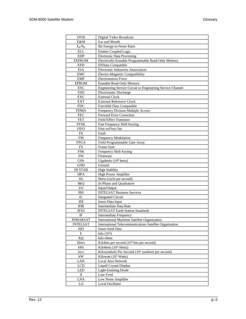
SDM-8000 Satellite Modem Glossary
Rev. 12 g–3
DVB Digital Video BroadcastE&M Ear and MouthEb/N0 Bit Energy-to-Noise RatioECL Emitter Coupled LogicEDP Electronic Data Processing
EEPROM Electrically-Erasable Programmable Read-Only MemoryEFD EFData CompatibleEIA Electronic Industries Association
EMC Electro-Magnetic CompatibilityEMF Electromotive Force
EPROM Erasable Read-Only MemoryESC Engineering Service Circuit or Engineering Service ChannelESD Electrostatic DischargeEXC External ClockEXT External Reference ClockFDC Fairchild Data Compatible
FDMA Frequency Division Multiple AccessFEC Forward Error CorrectionFET Field Effect Transistor
FFSK Fast Frequency Shift KeyingFIFO First in/First OutFlt FaultFM Frequency Modulation
FPGA Field Programmable Gate ArrayFS Frame Sync
FSK Frequency Shift KeyingFW FirmwareGHz Gigahertz (109 hertz)GND Ground
HI STAB High StabilityHPA High Power AmplifierHz Hertz (cycle per second)
I&Q In-Phase and QuadratureI/O Input/OutputIBS INTELSAT Business ServicesIC Integrated CircuitIDI Insert Data InputIDR Intermediate Data RateIESS INTELSAT Earth Station Standards
IF Intermediate FrequencyINMARSAT International Maritime Satellite OrganizationINTELSAT International Telecommunications Satellite Organization
ISD Insert Send Datak kilo (103)
KΩ kilo-ohmskbit/s Kilobits per second (103 bits per second)kHz Kilohertz (103 Hertz)ks/s Kilosymbols Per Second (103 symbols per second)kW Kilowatt (103 Watts)
LAN Local Area NetworkLCD Liquid Crystal DisplayLED Light-Emitting Diode
lf Line FeedLNA Low Noise AmplifierLO Local Oscillator

Glossary SDM-8000 Satellite Modem
g–4 Rev. 12
LSB Least Significant BitLSI Large Scale Integration (semiconductors)m mille (10-3)
M&C Monitor and ControlmA MilliamperesMax Maximum
Mbit/s Megabits per secondMC Monitor and ControlMFS Multiframe SyncMHz Megahertz (106 Hertz)Min Minimum or MinuteMod ModulatorMOP Modulated Output PowerMPC Microprocessor Controller
ms Millisecond (10-3 second)Ms/s Megasymbols per secondMSB Most Significant BitMUX Multiplexer
n nano (10-9)N/A Not Applicable
NACK Negative AcknowledgmentNC No Connection or Normally ClosedNO Normally Open
NRZ Non-Return to Zero (code)ns Nanosecond (10-9 second)
OQPSK Offset Quadrature Phase Shift KeyingOSC Oscillator
p pico (10-12)P-P Peak-to-Peak
P/AR Peak to Average RatioPAL Programmable Array LogicPC Printed Circuit
PCB Printed Circuit BoardPCM Pulse Code ModulationPECL Positive Emitter Coupled Logic
pF PicoFarads (10-12 Farads)PK PeakPLL Phase-Locked LoopPN Pseudo-Noise
PPM Parts Per MillionPS Power Supply
PSK Phase Shift KeyingPWB Printed Wiring BoardPWR PowerQAM Quadrature Amplitude ModulationQPSK Quadrature Phase Shift KeyingRAM Random Access MemoryRD Receive DataREF Reference
REPLS ReplacesRF Radio Frequency
RLSD Receive Line Signal DetectRMA Return Material AuthorizationROM Read-Only MemoryRR Receiver Ready

SDM-8000 Satellite Modem Glossary
Rev. 12 g–5
RS Ready to SendRT Receive Timing
RTS Request to SendRX Receive (Receiver)
RXCLK Receive ClockRXD Receive DataRZ Return-to-Zeros Second
S/N Signal-to-Noise RatioSCPC Single Channel Per CarrierSCR Serial Clock ReceiveSCT Serial Clock Transmit
SCTE Serial Clock Transmit ExternalSD Send DataSFS Subframe SyncSMS Satellite Multiservice SystemSN Signal-to-Noise RatioSSB Single-sideband
SSPA Solid State Power AmplifierST Send TimingSW Switch
SYNC SynchronizeTB Terminal Block
TCXO Temperature-Compensated Crystal OscillatorTDMA Time Division Multiple AccessTEMP TemperatureTERR Terrestrial
TP Test PointTT Terminal Timing
TTL Transistor-Transistor LogicTX Transmit (Transmitter)
TXCLK Transmit ClockTXD Transmit DataTXO TX OctetU/C Up converter
UART Universal Asynchronous Receiver/TransmitterUHF Ultra-high FrequencyUNK UnknownUS United StatesUW Unique WordV Volts
VAC Volts, Alternating CurrentVCO Voltage-Controlled Oscillator
VCXO Voltage-Controlled Crystal OscillatorVDC Volts, Direct Current
VSWR Voltage Standing Wave RatioW Watt
WG Waveguide

Glossary SDM-8000 Satellite Modem
g–6 Rev. 12
This page is intentionally left blank.

Rev. 12 i–1
I Index
64 kbit/s Service Channel Option, 5–98PSK, 5–19, 5–21, 5–19, 5–218PSK and 16QAM (Viterbi Decoder and Reed-Solomon
Codec), 5–19, 5–21, 5–19, 5–218PSK Encoder, 5–19, 5–21, C–14, 5–19, 5–21, C–14AC Power Connector, 5–9Acquisition Time, 2–14Alarms Connector and Pinouts (J10), 2–9, 2–10, 2–11,
2–14, C–20, 2–9, 2–10, 2–11, 2–14, C–20Asynchronous Interface Specifications, 2–14, B–1, B–45,
B–47, 2–14, B–1, B–45, B–47Automatic Uplink Power Control, B–7Automatic Uplink Power Control (AUPC), B–1, B–7, B–8,
B–10, B–1, B–7, B–8, B–10Backward Alarm, 2–13Backward Alarm Theory and Connections, 2–13Baseband Interface, 5–23BER Performance, B–30, C–2, B–30, C–2BPSK Encoding, C–5, C–7, C–9, C–11, C–15, C–17, C–5,
C–7, C–9, C–11, C–15, C–17Breakout Panels, 5–8Buffer Clock, 1–8Clocking Options, 1–8, 2–9, 1–8, 2–9Command/Response, 4–52, 5–17, 5–18, 4–52, 5–17, 5–18Configuration, 4–37, 6–23, 4–37, 6–23Configuration Commands/Responses, 4–37, 6–23, 4–37,
6–23Configuration Demodulator, A–4Configuration Interface, 4–12, 4–13, 6–3, 4–12, 4–13, 6–3Configuration Local AUPC, 4–16, 4–17, 4–18, 6–2, B–29,
4–16, 4–17, 4–18, 6–2, B–29Configuration Modulator, 4–26, 4–27, 4–26, 4–27Configuration Recall, 3–13, 4–8, 4–9, 3–13, 4–8, 4–9Configuration Save, 4–29Custom, 4–28
Custom Operation, 1–2, 2–12, 3–12, 3–14, 3–15, 3–18,3–22, 3–23, 4–4, 4–5, 4–49, 4–52, 4–61, 6–17, 6–19,6–20, 6–22, C–21, C–22, 1–2, 2–12, 3–12, 3–14, 3–15,3–18, 3–22, 3–23, 4–4, 4–5, 4–49, 4–52, 4–61, 6–17,6–19,6–20, 6–22, C–21, C–22
D&I, 1–2, 3–12, 3–14, 3–15, 3–18, 3–22, 3–23, 4–4, 4–5,4–49, 4–52, 4–61, 6–17, 6–19, 6–20, 6–22, C–21, C–22,1–2, 3–12, 3–14, 3–15, 3–18, 3–22, 3–23, 4–4, 4–5,–49, 4–52, 4–61, 6–17, 6–19, 6–20, 6–22, C–21, C–22
D&I G.703 Master/Master, 1–2, 1–5, 1–6, 1–8, 1–9, 2–7,2–11, 3–8, 3–9, 3–11, 3–12, 3–13, 3–15, 3–18, 3–21,4–4, 4–10, 4–14, 4–19, 4–20, 4–22, 4–23, 4–35, 4–36,4–52, 4–53, 4–61, 4–65, 4–66, 4–69, 4–74, 5–17, 6–12,6–13, 6–14, 6–20, 6–22, A–19, A–21, A–22, A–23,A–27, A–28, B–1, B–7, B–8, B–13, B–14, B–15, B–21,B–26, C–4, C–27, C–30, 1–2, 1–5, 1–6, 1–8, 1–9, 2–7,2–11, 3–8, 3–9, 3–11, 3–12, 3–13, 3–15, 3–18, 3–21,4–4, 4–10, 4–14, 4–19, 4–20, 4–22, 4–23, 4–35, 4–36,4–52, 4–53, 4–61, 4–65, 4–66, 4–69, 4–74, 5–17, 6–12,6–13, 6–14, 6–20, 6–22, A–19, A–21, A–22, A–23,A–27, A–28, B–1, B–7, B–8, B–13, B–14, B–15, B–21,B–26, C–4, C–27, C–30
D&I Interface Specification, 4–69, 4–74, 4–69, 4–74D&I Interface Specifications, 4–69, 4–74, 4–69, 4–74D&I with Asynchronous Overhead, C–27DATA I/O Interface Connector (J8), 1–6, B–1, B–7, B–8,
1–6, B–1, B–7, B–8Data Interface, 2–7Data Phase, A–23, A–28, B–7, B–9, B–22, C–25, C–28,
A–23, A–28, B–7, B–9, B–22, C–25, C–28Demodulator, A–23, A–28, B–7, B–9, B–22, C–25, C–28,
A–23, A–28, B–7, B–9, B–22, C–25, C–28
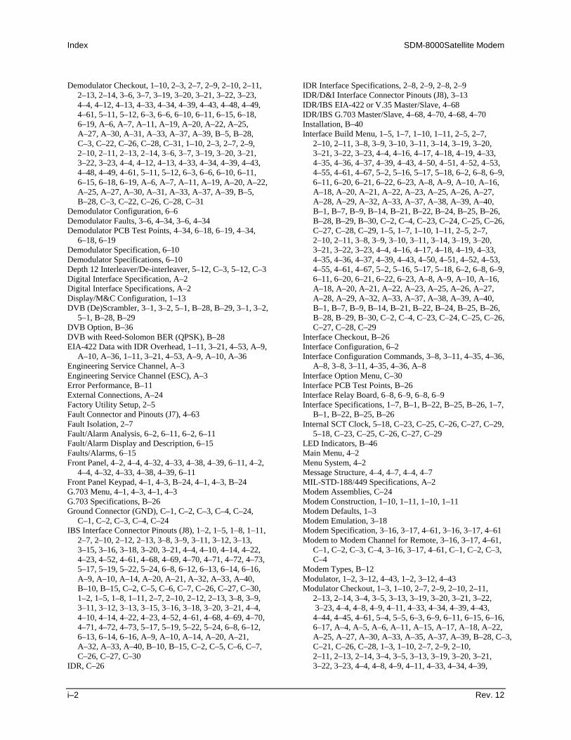
Index SDM-8000Satellite Modem
i–2 Rev. 12
Demodulator Checkout, 1–10, 2–3, 2–7, 2–9, 2–10, 2–11,2–13, 2–14, 3–6, 3–7, 3–19, 3–20, 3–21, 3–22, 3–23,4–4, 4–12, 4–13, 4–33, 4–34, 4–39, 4–43, 4–48, 4–49,4–61, 5–11, 5–12, 6–3, 6–6, 6–10, 6–11, 6–15, 6–18,6–19, A–6, A–7, A–11, A–19, A–20, A–22, A–25,A–27, A–30, A–31, A–33, A–37, A–39, B–5, B–28,C–3, C–22, C–26, C–28, C–31, 1–10, 2–3, 2–7, 2–9,2–10, 2–11, 2–13, 2–14, 3–6, 3–7, 3–19, 3–20, 3–21,3–22, 3–23, 4–4, 4–12, 4–13, 4–33, 4–34, 4–39, 4–43,4–48, 4–49, 4–61, 5–11, 5–12, 6–3, 6–6, 6–10, 6–11,6–15, 6–18, 6–19, A–6, A–7, A–11, A–19, A–20, A–22,A–25, A–27, A–30, A–31, A–33, A–37, A–39, B–5,B–28, C–3, C–22, C–26, C–28, C–31
Demodulator Configuration, 6–6Demodulator Faults, 3–6, 4–34, 3–6, 4–34Demodulator PCB Test Points, 4–34, 6–18, 6–19, 4–34,
6–18, 6–19Demodulator Specification, 6–10Demodulator Specifications, 6–10Depth 12 Interleaver/De-interleaver, 5–12, C–3, 5–12, C–3Digital Interface Specification, A–2Digital Interface Specifications, A–2Display/M&C Configuration, 1–13DVB (De)Scrambler, 3–1, 3–2, 5–1, B–28, B–29, 3–1, 3–2,
5–1, B–28, B–29DVB Option, B–36DVB with Reed-Solomon BER (QPSK), B–28EIA-422 Data with IDR Overhead, 1–11, 3–21, 4–53, A–9,
A–10, A–36, 1–11, 3–21, 4–53, A–9, A–10, A–36Engineering Service Channel, A–3Engineering Service Channel (ESC), A–3Error Performance, B–11External Connections, A–24Factory Utility Setup, 2–5Fault Connector and Pinouts (J7), 4–63Fault Isolation, 2–7Fault/Alarm Analysis, 6–2, 6–11, 6–2, 6–11Fault/Alarm Display and Description, 6–15Faults/Alarms, 6–15Front Panel, 4–2, 4–4, 4–32, 4–33, 4–38, 4–39, 6–11, 4–2,
4–4, 4–32, 4–33, 4–38, 4–39, 6–11Front Panel Keypad, 4–1, 4–3, B–24, 4–1, 4–3, B–24G.703 Menu, 4–1, 4–3, 4–1, 4–3G.703 Specifications, B–26Ground Connector (GND), C–1, C–2, C–3, C–4, C–24,
C–1, C–2, C–3, C–4, C–24IBS Interface Connector Pinouts (J8), 1–2, 1–5, 1–8, 1–11,
2–7, 2–10, 2–12, 2–13, 3–8, 3–9, 3–11, 3–12, 3–13,3–15, 3–16, 3–18, 3–20, 3–21, 4–4, 4–10, 4–14, 4–22,4–23, 4–52, 4–61, 4–68, 4–69, 4–70, 4–71, 4–72, 4–73,5–17, 5–19, 5–22, 5–24, 6–8, 6–12, 6–13, 6–14, 6–16,A–9, A–10, A–14, A–20, A–21, A–32, A–33, A–40,B–10, B–15, C–2, C–5, C–6, C–7, C–26, C–27, C–30,1–2, 1–5, 1–8, 1–11, 2–7, 2–10, 2–12, 2–13, 3–8, 3–9,3–11, 3–12, 3–13, 3–15, 3–16, 3–18, 3–20, 3–21, 4–4,4–10, 4–14, 4–22, 4–23, 4–52, 4–61, 4–68, 4–69, 4–70,4–71, 4–72, 4–73, 5–17, 5–19, 5–22, 5–24, 6–8, 6–12,6–13, 6–14, 6–16, A–9, A–10, A–14, A–20, A–21,A–32, A–33, A–40, B–10, B–15, C–2, C–5, C–6, C–7,C–26, C–27, C–30
IDR, C–26
IDR Interface Specifications, 2–8, 2–9, 2–8, 2–9IDR/D&I Interface Connector Pinouts (J8), 3–13IDR/IBS EIA-422 or V.35 Master/Slave, 4–68IDR/IBS G.703 Master/Slave, 4–68, 4–70, 4–68, 4–70Installation, B–40Interface Build Menu, 1–5, 1–7, 1–10, 1–11, 2–5, 2–7,
2–10, 2–11, 3–8, 3–9, 3–10, 3–11, 3–14, 3–19, 3–20,3–21, 3–22, 3–23, 4–4, 4–16, 4–17, 4–18, 4–19, 4–33,4–35, 4–36, 4–37, 4–39, 4–43, 4–50, 4–51, 4–52, 4–53,4–55, 4–61, 4–67, 5–2, 5–16, 5–17, 5–18, 6–2, 6–8, 6–9,6–11, 6–20, 6–21, 6–22, 6–23, A–8, A–9, A–10, A–16,A–18, A–20, A–21, A–22, A–23, A–25, A–26, A–27,A–28, A–29, A–32, A–33, A–37, A–38, A–39, A–40,B–1, B–7, B–9, B–14, B–21, B–22, B–24, B–25, B–26,B–28, B–29, B–30, C–2, C–4, C–23, C–24, C–25, C–26,C–27, C–28, C–29, 1–5, 1–7, 1–10, 1–11, 2–5, 2–7,2–10, 2–11, 3–8, 3–9, 3–10, 3–11, 3–14, 3–19, 3–20,3–21, 3–22, 3–23, 4–4, 4–16, 4–17, 4–18, 4–19, 4–33,4–35, 4–36, 4–37, 4–39, 4–43, 4–50, 4–51, 4–52, 4–53,4–55, 4–61, 4–67, 5–2, 5–16, 5–17, 5–18, 6–2, 6–8, 6–9,6–11, 6–20, 6–21, 6–22, 6–23, A–8, A–9, A–10, A–16,A–18, A–20, A–21, A–22, A–23, A–25, A–26, A–27,A–28, A–29, A–32, A–33, A–37, A–38, A–39, A–40,B–1, B–7, B–9, B–14, B–21, B–22, B–24, B–25, B–26,B–28, B–29, B–30, C–2, C–4, C–23, C–24, C–25, C–26,C–27, C–28, C–29
Interface Checkout, B–26Interface Configuration, 6–2Interface Configuration Commands, 3–8, 3–11, 4–35, 4–36,
A–8, 3–8, 3–11, 4–35, 4–36, A–8Interface Option Menu, C–30Interface PCB Test Points, B–26Interface Relay Board, 6–8, 6–9, 6–8, 6–9Interface Specifications, 1–7, B–1, B–22, B–25, B–26, 1–7,
B–1, B–22, B–25, B–26Internal SCT Clock, 5–18, C–23, C–25, C–26, C–27, C–29,
5–18, C–23, C–25, C–26, C–27, C–29LED Indicators, B–46Main Menu, 4–2Menu System, 4–2Message Structure, 4–4, 4–7, 4–4, 4–7MIL-STD-188/449 Specifications, A–2Modem Assemblies, C–24Modem Construction, 1–10, 1–11, 1–10, 1–11Modem Defaults, 1–3Modem Emulation, 3–18Modem Specification, 3–16, 3–17, 4–61, 3–16, 3–17, 4–61Modem to Modem Channel for Remote, 3–16, 3–17, 4–61,
C–1, C–2, C–3, C–4, 3–16, 3–17, 4–61, C–1, C–2, C–3,C–4
Modem Types, B–12Modulator, 1–2, 3–12, 4–43, 1–2, 3–12, 4–43Modulator Checkout, 1–3, 1–10, 2–7, 2–9, 2–10, 2–11,
2–13, 2–14, 3–4, 3–5, 3–13, 3–19, 3–20, 3–21, 3–22, 3–23, 4–4, 4–8, 4–9, 4–11, 4–33, 4–34, 4–39, 4–43,4–44, 4–45, 4–61, 5–4, 5–5, 6–3, 6–9, 6–11, 6–15, 6–16,6–17, A–4, A–5, A–6, A–11, A–15, A–17, A–18, A–22,A–25, A–27, A–30, A–33, A–35, A–37, A–39, B–28, C–3,C–21, C–26, C–28, 1–3, 1–10, 2–7, 2–9, 2–10,2–11, 2–13, 2–14, 3–4, 3–5, 3–13, 3–19, 3–20, 3–21,3–22, 3–23, 4–4, 4–8, 4–9, 4–11, 4–33, 4–34, 4–39,

SDM-8000Satellite Modem Index
Rev. 12 i–3
4–43, 4–44, 4–45, 4–61, 5–4, 5–5, 6–3, 6–9, 6–11, 6–15,6–16, 6–17, A–4, A–5, A–6, A–11, A–15, A–17, A–18,A–22, A–25, A–27, A–30, A–33, A–35, A–37, A–39,B–28, C–3, C–21, C–26, C–28
Modulator Configuration, 6–3Modulator Faults, 3–4, 4–34, 3–4, 4–34Modulator PCB Test Points, 4–34, 6–16, 6–17, 4–34, 6–16,
6–17Modulator Specifications, 6–9Module Replacement, 5–5, C–3, C–21, 5–5, C–3, C–21Monitor, 6–24Nyquist Filters, 1–4, 1–10, 4–2, 4–4, 4–30, 4–31, 4–41,
4–42, 6–3, A–23, A–28, A–38, A–39, 1–4, 1–10, 4–2,4–4, 4–30, 4–31, 4–41, 4–42, 6–3, A–23, A–28, A–38,A–39
Open Network, 5–5, 5–12, B–42, C–32, 5–5, 5–12, B–42,C–32
Operation, 5–17, 5–19, 5–17, 5–19Operational Check, 1–8, 1–9, 2–2, 3–13, 3–14, 3–16, 3–23,
4–57, 4–61, 5–2, 5–5, 5–12, 5–15, 5–18, A–5, A–7,A–14, A–17, A–18, A–19, A–20, A–35, B–3, B–7,B–15, B–22, B–24, C–21, C–22, C–29, 1–8, 1–9, 2–2,3–13, 3–14, 3–16, 3–23, 4–57, 4–61, 5–2, 5–5, 5–12,5–15, 5–18, A–5, A–7, A–14, A–17, A–18, A–19,A–20, A–35, B–3, B–7, B–15, B–22, B–24, C–21,C–22, C–29
Option Requirements, B–24Options, B–45Overview, 1–5, 2–2, 4–68, 1–5, 2–2, 4–68PCB Test Points, 1–2Performance with Noise, Sequential Decoder, BPSK,
QPSK, and 1544 kbits/s, C–12Performance with Noise, Viterbi Decoder, and 8PSK 5/6,
C–14Plesiochronous Buffer, 6–8, 6–9, 6–10, C–6, 6–8, 6–9,
6–10, C–6QPSK Encoding, B–40Receive Demultiplexer, 5–8Receive IF Test Modes, C–20Receive Interface Faults, B–7, B–10, B–7, B–10Receive Terrestrial 204 Byte Framing Format, B–31Reed-Solomon, 6–21, 6–22, B–32, 6–21, 6–22, B–32Reed-Solomon Codec, B–32Reed-Solomon Decoder, 1–6, 4–9, 4–11, 4–13, 4–15, 4–39,
5–17, B–1, B–15, B–16, B–17, B–20, B–21, 1–6, 4–9,4–11, 4–13, 4–15, 4–39, 5–17, B–1, B–15, B–16, B–17,B–20, B–21
Reed-Solomon Specifications (Optional), A–5, A–17,A–18, A–33, B–16, B–18, A–5, A–17, A–18, A–33,B–16, B–18
Remote AUPC, 3–3, 3–18, 3–23, 3–3, 3–18, 3–23Remote AUPC Monitor, 4–40, 4–41, 4–40, 4–41Remote Baud Rate, 4–42Remote Connector and Pinouts (J6), 3–3, 3–18, 3–23, 3–3,
3–18, 3–23Remote Interface Specification, 2–6Restriction for SCT Clock, 5–6Revision Emulation, 3–14
RF Input Connector (CP2), 3–14, 3–15, 4–43, 3–14, 3–15,4–43
RF Output Connector (CP1), 2–6RX Interface Faults, 2–6Sequential Decoder, 4–36Sequential Decoder BER (1544 kbit/s), 1–5, 1–11, 3–6,
5–12, B–1, B–2, B–6, C–10, 1–5, 1–11, 3–6, 5–12, B–1,B–2, B–6, C–10
Signal Space Mapping, C–10Software Configuration, B–41Specification, 3–12Specifications, 3–12Start Character, 5–12, 5–14, 5–18, B–2, B–7, B–15, C–1,
C–2, C–3, C–4, C–23, C–24, C–25, C–26, C–27, C–29,C–30, 5–12, 5–14, 5–18, B–2, B–7, B–15, C–1, C–2,C–3, C–4, C–23, C–24, C–25, C–26, C–27, C–29, C–30
Status Commands/Responses, A–2Stored Faults/Alarms, 4–2, 4–4, 4–38, 4–39, 4–57, A–14,
A–17, A–22, A–23, A–23, A–27, A–28, 4–2, 4–4, 4–38,4–39, 4–57, A–14, A–17, A–22, A–23, A–23, A–27,A–28
Sync Decoder, B–35Sync Decoder (Correlator), B–35System, C–31System Checkout, 1–2, 2–2, 3–3, 3–14, 3–23, 4–4, 4–7,
4–43, 4–56, 4–57, 4–62, 6–1, 6–11, A–14, A–18, A–20,A–33, 1–2, 2–2, 3–3, 3–14, 3–23, 4–4, 4–7, 4–43, 4–56,4–57, 4–62, 6–1, 6–11, A–14, A–18, A–20, A–33
System Faults/Alarms, 6–1System Options, 6–11System-Related Specifications, 2–2Terrestrial 204 Byte Framing Format, B–31Theory of Modulation Types, B–32Theory of Operation, 5–7Transmit Interface Faults, 5–2, 5–5, 5–12, 5–15, 5–18,
B–3, B–7, B–15, B–22, C–30, 5–2, 5–5, 5–12, 5–15,5–18, B–3, B–7, B–15, B–22, C–30
Transmit Terrestrial 188 Byte Frame Format, B–7, B–9, B–7, B–9
Transmit Terrestrial No Framing Format, B–33Transport Error Indicator, B–34TX Interface Faults, B–7, B–9, B–7, B–9Type X (1 through 4), 4–35Type X (1 through 5), 4–35Typical Spectral Occupancy, 3–23Unpacking, 4–39Utility Demodulator, 2–12, 3–3, 3–12, 3–13, 3–14, 4–2,
4–4, 4–10, 4–19, 4–22, 4–43, 4–44, 4–45, 4–48, 4–49,4–50, 4–51, 4–52, 4–56, 4–57, 4–60, 4–61, 4–62, 4–63,6–18, 6–20, 6–21, B–5, B–14, B–21, B–24, 2–12, 3–3,3–12, 3–13, 3–14, 4–2, 4–4, 4–10, 4–19, 4–22, 4–43,4–44, 4–45, 4–48, 4–49, 4–50, 4–51, 4–52, 4–56, 4–57,4–60, 4–61, 4–62, 4–63, 6–18, 6–20, 6–21, B–5, B–14,B–21, B–24
Utility Modem Type, 4–19, 4–50, 4–51, 4–52, B–21, B–24,4–19, 4–50, 4–51, 4–52, B–21, B–24
Utility System Functions, 4–44, 4–45, 4–44, 4–45Viterbi Decoder, C–25Viterbi Decoder BER, C–6

Index SDM-8000Satellite Modem
i–4 Rev. 12
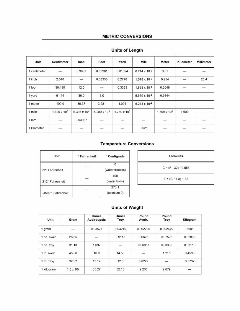
METRIC CONVERSIONS
Units of Length
Unit
Centimeter
Inch
Foot
Yard
Mile
Meter
Kilometer
Millimeter
1 centimeter — 0.3937 0.03281 0.01094 6.214 x 10⁻⁶ 0.01 — —
1 inch 2.540 — 0.08333 0.2778 1.578 x 10⁻⁵ 0.254 — 25.4
1 foot 30.480 12.0 — 0.3333 1.893 x 10⁻⁴ 0.3048 — —
1 yard 91.44 36.0 3.0 — 5.679 x 10⁻⁴ 0.9144 — —
1 meter 100.0 39.37 3.281 1.094 6.214 x 10⁻⁴ — — —
1 mile 1.609 x 10⁵ 6.336 x 10⁴ 5.280 x 10³ 1.760 x 10³ — 1.609 x 10³ 1.609 —
1 mm — 0.03937 — — — — — —
1 kilometer — — — — 0.621 — — —
Temperature Conversions
Units of Weight
Unit
Gram
Ounce Avoirdupois
Ounce Troy
Pound Avoir.
Pound Troy
Kilogram
1 gram — 0.03527 0.03215 0.002205 0.002679 0.001
1 oz. avoir. 28.35 — 0.9115 0.0625 0.07595 0.02835
1 oz. troy 31.10 1.097 — 0.06857 0.08333 0.03110
1 lb. avoir. 453.6 16.0 14.58 — 1.215 0.4536
1 lb. Troy 373.2 13.17 12.0 0.8229 — 0.3732
1 kilogram 1.0 x 10³ 35.27 32.15 2.205 2.679 —
Unit
° Fahrenheit
° Centigrade
32° Fahrenheit —
0
(water freezes)
212° Fahrenheit —
100
(water boils)
-459.6° Fahrenheit —
273.1
(absolute 0)
Formulas
C = (F - 32) * 0.555
F = (C * 1.8) + 32

2114 WEST 7TH STREET TEMPE ARIZONA 85281 USA 480 • 333 • 2200 PHONE
480 • 333 • 2161 FAX