SDH Series Manual - introl.pl
220
SDH Series Manual
Transcript of SDH Series Manual - introl.pl
SDH Series Manual

SDH Series Manual
i
Preface
We appreciate very much for your purchasing of Shihlin servo products. This manual will be a helpful instruction to install, wire, inspect, and operate your Shihlin servo drive and motor.
injury.
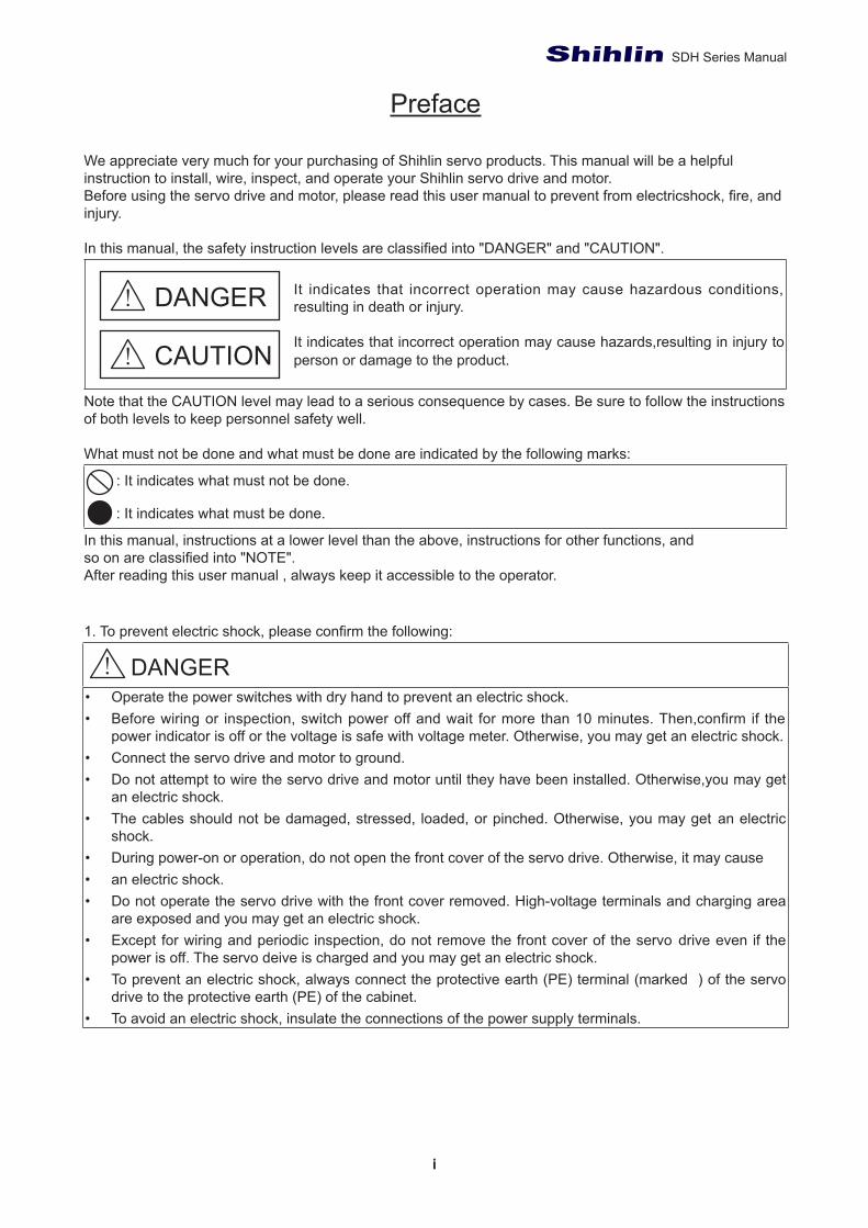
It indicates that incorrect operation may cause hazardous conditions, resulting in death or injury.
It indicates that incorrect operation may cause hazards,resulting in injury to person or damage to the product.
Note that the CAUTION level may lead to a serious consequence by cases. Be sure to follow the instructions of both levels to keep personnel safety well.
What must not be done and what must be done are indicated by the following marks:
: It indicates what must not be done.
: It indicates what must be done.
In this manual, instructions at a lower level than the above, instructions for other functions, and
After reading this user manual , always keep it accessible to the operator.
1.
• Operate the power switches with dry hand to prevent an electric shock.• Before wiring or inspection, switch power off and wait for more than 10 minutes. Then,confirm if the
power indicator is off or the voltage is safe with voltage meter. Otherwise, you may get an electric shock.• Connect the servo drive and motor to ground.• Do not attempt to wire the servo drive and motor until they have been installed. Otherwise,you may get
an electric shock.• The cables should not be damaged, stressed, loaded, or pinched. Otherwise, you may get an electric
shock.• During power-on or operation, do not open the front cover of the servo drive. Otherwise, it may cause• an electric shock.• Do not operate the servo drive with the front cover removed. High-voltage terminals and charging area
are exposed and you may get an electric shock.• Except for wiring and periodic inspection, do not remove the front cover of the servo drive even if the
power is off. The servo deive is charged and you may get an electric shock.• To prevent an electric shock, always connect the protective earth (PE) terminal (marked ) of the servo
drive to the protective earth (PE) of the cabinet.• To avoid an electric shock, insulate the connections of the power supply terminals.
DANGER
CAUTION
DANGER
SDH Series Manual
ii
2.
• Install the servo drive, servo motor, and regenerative resistor on incombustible material. Installing them
• When the servo drive failure, please t shuts down the power supply on the side of the servo drive’s large current which
• When using the regenerative resistor, switch power off with the alarm signal. Otherwise, a regenerative transistor malfunction or the like may overheat the regenerative resistor
• Provide adequate protection to prevent screws and other conductive matter, oil and other combustible matter from entering the servo drivw and servo motor.
• Always connect a molded-case circuit breaker, or a fuse to each servo drive between the power supply and the main circuit power supply of the servo drive.
3. To prevent injury, note the following:
• • a burst, damage, etc. may occur.• Connect the terminals correctly to prevent a burst, damage, etc.• Ensure that polarity (+ , - ) is correct. Otherwise, a burst, damage, etc. may occur.• Don’t touch the servo drive heat sink, regenerative resistor, servo motor, etc. which may be hot while
power is on or for some time after power-off. Otherwise,a injury, damage, etc. may occur.
4. Additional instructionsThe following instructions should also be fully noted. Incorrect handling may cause a fault, injury, electric
(1) Transportation and installation
• Transport the products correctly according to their mass.• • Do not hold the motor’s cable, shaft and encoder when transporting the servo motor. • Install the servo drive and the servo motor in a load-bearing place in accordance with the manual.• Do not get on or put heavy load on the equipment.• method.• drive and the cabinet walls or other equipment.• Do not install or operate the servo drive and servo motor which have been damaged or have any parts
missing.• Do not block the intake and exhaust areas of the servo drive. Otherwise, it may cause a malfunction.• Do not drop or strike the servo drive and servo motor. Isolate them from all impact loads.• Please contact the service deparment of Shihlin When you want to keep for a long time.
CAUTION
CAUTION
CAUTION
SDH Series Manual
iii
(2) Wiring
• • and servo drive.• To avoid a malfunction, connect the wires to the correct phase terminals (U, V, and W) of the servo• drive and servo motor.• Connect the servo drive power output (U, V, and W) to the servo motor power input (U, V, and W)
directly. Do not let a magnetic contactor, etc. intervene. Otherwise, it may cause a malfunction.•
direction. Otherwise, the emergency stop and other protective circuits may not operate.• When the cable is not tightened enough to the terminal block, the cable or terminal block may generate
(3) Test run and adjustment
• Before operation, check the parameter settings. Improper settings may cause some machines to perform unexpected operation.
• Never adjust or change the parameter values extremely as it will make operation unstable.
(4) Usage
• Provide an external emergency stop circuit to ensure that operation can be stopped and power switched off immediately.
• Do not disassemble, repair, or modify the equipment.• Before resetting an alarm, make sure that the run signal of the servo drive is off in order to prevent a
sudden restart. Otherwise, it may cause an accident.•
interference may be given to the electronic equipment used near the servo drive.• Burning or breaking a servo drive may cause a toxic gas. Do not burn or break it.• Use the servo drive• The electromagnetic brake on the servo motor is designed to hold the motor shaft and should not be
used for ordinary braking.
(5) Maintenance and inspection
• Ensure that the power indicator is off before maintenance or inspection performed.• Only personnel who have been trained should conduct maintenance and inspection.• Do not try to disassemble the servo drive or motor which any fault occurred.• As power is still applied, not to connect or break the UVW wire of servo drive and servo motor to prevent
electrical shock.• he electromagnetic brake on the servo motor is designed to hold the motor shaft and should not be used
for ordinary braking.NOTE : This manual may be revised without prior notice. Please consult our agent or download the most updated version at http://www.seec.com.tw/en/ .
CAUTION
CAUTION
CAUTION
CAUTION

SDH Series Manual
iv
Index
1. Production inspection and model descriptions ------------------------------------------------11.1 Summary -------------------------------------------------------------------------------------------------11.2 Inspection ------------------------------------------------------------------------------------------------11.3 Servo drive appearance and panel descriptions -----------------------------------------------31.4 Overview of servo drive operation modes -------------------------------------------------------4
41.5
2. Installation --------------------------------------------------------------------------------------------------52.1 Cautions and storage methods ---------------------------------------------------------------------52.2 The environment conditions of installation --------------------------------------------------------52.3 Installation direction and space ---------------------------------------------------------------------5
3. Wiring and signals ----------------------------------------------------------------------------------------7
---------------------11
3.1 Connections between main power source and peripheral devices ------------------------73.1.1 Wiring diagram of peripheral devices(below 1KW) ------------------------------------73.1.2 Wiring diagram of peripheral devices(1.5KW~3KW) ----------------------------------83.1.3 Wiring diagram of peripheral devices(above 5KW) ------------------------------------93.1.4 Descriptions for drive’s connectors and terminals3.1.5 Wiring method of power source ------------------------------------------------------------103.1.6
3.2 Functional block diagram of Shihlin servo -------------------------------------------------------123.3 CN1 I/O signal wires instruction -------------------------------------------------------------------14
3.3.1 CN1 terminal layout --------------------------------------------------------------------------143.3.2 Signal description of CN1 terminal --------------------------------------------------------163.3.3 Interface wiring diagram ---------------------------------------------------------------------253.3.4 ------------------------------29
3.4 CN2 Encoder signal wiring and description ----------------------------------------------------303.4.1 Encoder signal wiring and description ---------------------------------------------------30
3.5 CN2L Encoder -----------------------------------------------------------------------------------------313.6 CN3 communication port signal wiring and description -------------------------------------323.7 CN4 USB communication port ---------------------------------------------------------------------323.8 Standard wiring method -----------------------------------------------------------------------------32
3.8.1 Wiring diagram of position control(Pr Mode) -------------------------------------------333.8.2 Wiring diagram of position control(Pt Mode) -------------------------------------------343.8.3 Wiring diagram of speed control(S Mode) ----------------------------------------------353.8.4 Wiring diagram of torque control(T Mode) ----------------------------------------------363.8.5 Wiring diagram with 1PG --------------------------------------------------------------------373.8.6 Wiring diagram with 10PG ------------------------------------------------------------------383.8.7 Wiring diagram with 10GM -----------------------------------------------------------------393.8.8 Wiring diagram with 20GM -----------------------------------------------------------------40
---------------------------------------9
SDH Series Manual
v
3.8.9 Wiring diagram with FX3U ------------------------------------------------------------------413.8.10 Wiring diagram with QD75 ----------------------------------------------------------------423.8.11 Wiring diagram with Gantry ---------------------------------------------------------------43
4. Panel display and operation -------------------------------------------------------------------------444.1 Panel components ------------------------------------------------------------------------------------444.2 --------------------------------------------------------------------------------------444.3 Status display ------------------------------------------------------------------------------------------454.4 Alarm display -------------------------------------------------------------------------------------------484.5 Diagnostic display ------------------------------------------------------------------------------------49
4.5.1 Indication of external I/O signals ----------------------------------------------------------494.5.2 DO forced output ------------------------------------------------------------------------------504.5.3 JOG test -----------------------------------------------------------------------------------------514.5.4 Positioning test --------------------------------------------------------------------------------524.5.5 Automatic offset of analog command input ---------------------------------------------534.5.6 Inertia estimation ------------------------------------------------------------------------------54
4.6 Parameter display ------------------------------------------------------------------------------------544.6.1 16bit parameter setting method -----------------------------------------------------------544.6.2 32bit parameter setting method -----------------------------------------------------------55
5. Operation ---------------------------------------------------------------------------------------------------595.1 Checklist before operation --------------------------------------------------------------------------595.2 Idle operation ------------------------------------------------------------------------------------------59
5.2.1 Idle JOG test -----------------------------------------------------------------------------------595.2.2 Idle positioning test ---------------------------------------------------------------------------60
5.3 Tuning process ----------------------------------------------------------------------------------------615.3.1 Abstract -----------------------------------------------------------------------------------------615.3.2 Auto-gain tuning mode ----------------------------------------------------------------------625.3.3 Manual gain tuning mode -------------------------------------------------------------------65
5.4 Parameter setting and operation for position control mode --------------------------------675.5 Parameter setting and operation for speed control mode -----------------------------------685.6 Parameter setting and operation for torque control mode -----------------------------------69
6. Control function ------------------------------------------------------------------------------------------706.1 Control mode option ----------------------------------------------------------------------------------706.2 Torque control mode ---------------------------------------------------------------------------------70
6.2.1 Output proportion of maximum torque analog command ---------------------------706.2.2 Torque analog command offset ------------------------------------------------------------716.2.3 Torque analog command smoothing -----------------------------------------------------716.2.4 Torque limit of torque control mode -------------------------------------------------------726.2.5 Speed limit of torque control mode -------------------------------------------------------72
6.3 Speed control mode ----------------------------------------------------------------------------------736.3.1 Selection of speed command --------------------------------------------------------------73
SDH Series Manual
vi
6.3.2 Output speed of maximum speed analog command ---------------------------------746.3.3 Speed analog command smoothing -----------------------------------------------------746.3.4 Torque limit of speed control mode -------------------------------------------------------766.3.5 Adjustment of speed loop gain -------------------------------------------------------------776.3.6 ---------------------------786.3.7 Gain switch function --------------------------------------------------------------------------81
6.4 Position control mode --------------------------------------------------------------------------------836.4.1 External pulse-train command(Pt mode) ------------------------------------------------846.4.2 Inner register command(Pr mode) --------------------------------------------------------856.4.3 Position command smoothing -------------------------------------------------------------866.4.4 Electronic gear ratio --------------------------------------------------------------------------876.4.5 Torque limit of position control mode -----------------------------------------------------886.4.6 Position loop gain -----------------------------------------------------------------------------88
6.5 Hybrid control mode ----------------------------------------------------------------------------------896.5.1 Position/speed hybrid mode ----------------------------------------------------------------906.5.2 Speed/torque hybrid mode -----------------------------------------------------------------906.5.3 Torque/Position hybrid mode ---------------------------------------------------------------91
6.6 Other functions ----------------------------------------------------------------------------------------926.6.1 Selection of brake resistor ------------------------------------------------------------------926.6.2 Analog monitor output -----------------------------------------------------------------------946.6.3 Operation of electromagnetic brake interlock ------------------------------------------95
7. PR (Procedure) Procedure control function description ------------------------------------977.1 Pr mode description ----------------------------------------------------------------------------------977.2 The difference of PR mode between SDH and SDA ------------------------------------------977.3 DI/DO and timing of PR mode ----------------------------------------------------------------------977.4 Parameter setting of PR mode ---------------------------------------------------------------------987.5 The status of procedure connection ------------------------------------------------------------103
8. Parameters -----------------------------------------------------------------------------------------------1068.1 --------------------------------------------------------------------------------1068.2 Parameter list -----------------------------------------------------------------------------------------1078.3 Parameter details list -------------------------------------------------------------------------------118
9. Communication functions --------------------------------------------------------------------------1499.1.Communication interface and wiring -----------------------------------------------------------1499.2 Relevant parameters of communication -------------------------------------------------------1519.3 Modbus protoco -------------------------------------------------------------------------------------151
A. ASCII mode ---------------------------------------------------------------------------------------157B. RTU mode ----------------------------------------------------------------------------------------157
9.4. Communication parameter write-in and read-out -------------------------------------------158
10. Inspection and Maintenance ----------------------------------------------------------------------163
SDH Series Manual
vii
10.1 Basic Inspection -----------------------------------------------------------------------------------16310.2 Maintenance ----------------------------------------------------------------------------------------16310.3 Life of consumable components ---------------------------------------------------------------163
11. Troubleshooting --------------------------------------------------------------------------------------16411.1. Alarm list --------------------------------------------------------------------------------------------16411.2. Alarm cause and remedy ------------------------------------------------------------------------166
13. Motor characteristic ---------------------------------------------------------------------------------18513.1 Speed-torque curves of low inertia motor ----------------------------------------------------18513.2 Speed-torque curves of medium inertia motor ----------------------------------------------18513.3 Overload protection -------------------------------------------------------------------------------186
14. Absolute servo system -----------------------------------------------------------------------------18814.1 Mitsubishi Absolute Position Detection System --------------------------------------------190
14.1.1 Signal explanation -------------------------------------------------------------------------19014.1.2 Startup procedure -------------------------------------------------------------------------19014.1.3 Absolute position data transfer protocol ----------------------------------------------191
14.2 Delta Absolute Position Detection System --------------------------------------------------19814.2.1 Signal explanation -------------------------------------------------------------------------19814.2.2 Start procedure ----------------------------------------------------------------------------19814.2.3 Use Digital Inputs/Outputs to Initialize an Absolute System --------------------19914.2.4 Use Parameters to Initialize an Absolute System ----------------------------------19914.2.5 Absolute position data communication protoco ------------------------------------200
Appendix A Accessories --------------------------------------------------------------------------------202
Appendix B Parameters communication address ----------------------------------------------207
Appendix C Version information ---------------------------------------------------------------------209
12. 12.1 12.2 Dimensions of servo drives ---------------------------------------------------------------------17712.3 SMH-L□□□R30□□□ series ------------------------17912.4 SMH-M□□□R20□□□series ------------------18012.5 Dimensions of low inertia motor ----------------------------------------------------------------18112.6 Permissible shaft load of low inertia motor --------------------------------------------------18212.7 Dimensions of medium inertia motors --------------------------------------------------------18212.8 Permissible shaft load of medium inertia motor --------------------------------------------18312.9 Precision of motor shaft --------------------------------------------------------------------------18312.10 --------------------------------------------183
-----------------------------------------------------------------------------------------175------------------------------------------------------------------175
1
Chapter 1.
1. Production inspection and model descriptions
1.1 Summary
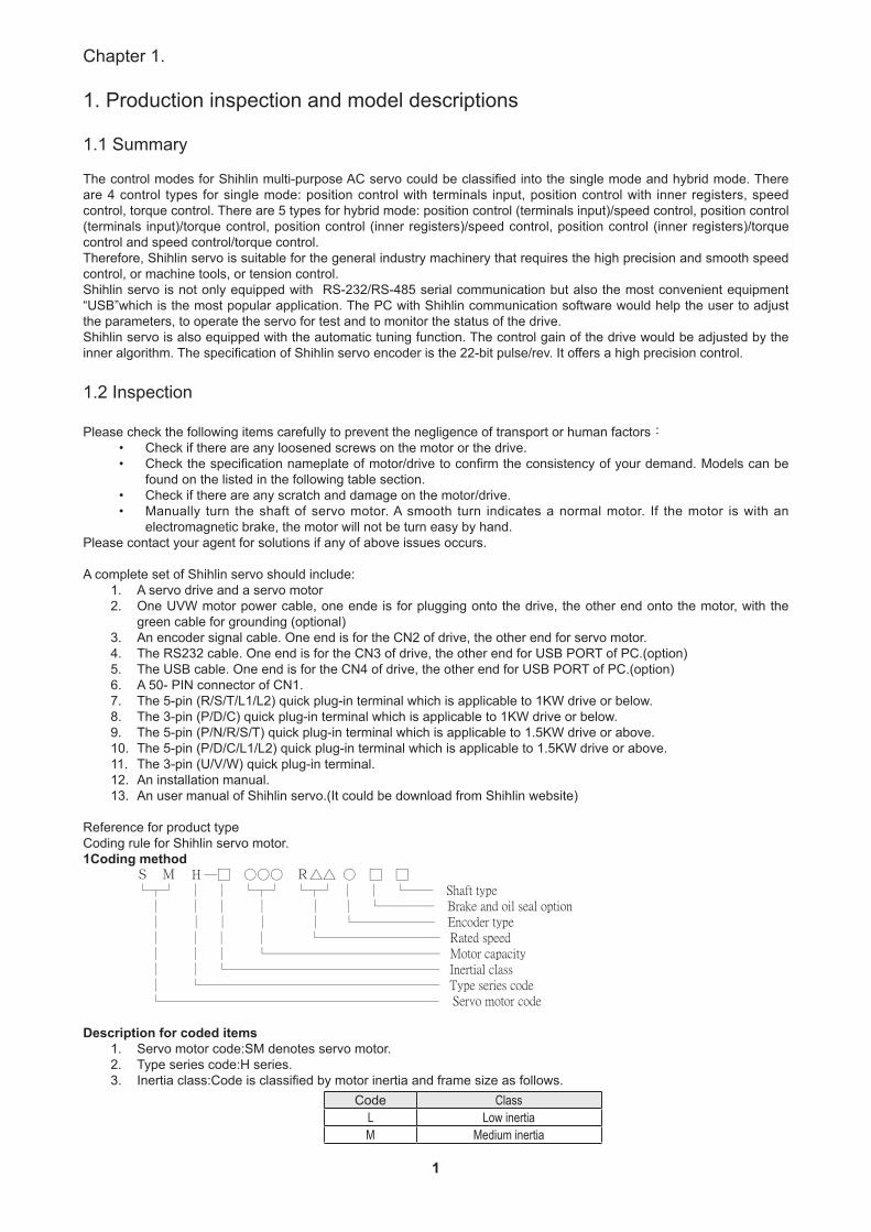
The control modes for Shihlin multi-purpose AC servo could be classified into the single mode and hybrid mode. There are 4 control types for single mode: position control with terminals input, position control with inner registers, speed control, torque control. There are 5 types for hybrid mode: position control (terminals input)/speed control, position control (terminals input)/torque control, position control (inner registers)/speed control, position control (inner registers)/torque control and speed control/torque control.Therefore, Shihlin servo is suitable for the general industry machinery that requires the high precision and smooth speed control, or machine tools, or tension control.Shihlin servo is not only equipped with RS-232/RS-485 serial communication but also the most convenient equipment “USB”which is the most popular application. The PC with Shihlin communication software would help the user to adjust the parameters, to operate the servo for test and to monitor the status of the drive.Shihlin servo is also equipped with the automatic tuning function. The control gain of the drive would be adjusted by the inner algorithm. The specification of Shihlin servo encoder is the 22-bit pulse/rev. It offers a high precision control.
1.2 Inspection
Please check the following items carefully to prevent the negligence of transport or human factors:
• Check if there are any loosened screws on the motor or the drive.• Check the specification nameplate of motor/drive to confirm the consistency of your demand. Models can be
found on the listed in the following table section.• Check if there are any scratch and damage on the motor/drive.• Manually turn the shaft of servo motor. A smooth turn indicates a normal motor. If the motor is with an
electromagnetic brake, the motor will not be turn easy by hand.Please contact your agent for solutions if any of above issues occurs.
A complete set of Shihlin servo should include:1. A servo drive and a servo motor2. One UVW motor power cable, one ende is for plugging onto the drive, the other end onto the motor, with the
green cable for grounding (optional)3. An encoder signal cable. One end is for the CN2 of drive, the other end for servo motor.4. The RS232 cable. One end is for the CN3 of drive, the other end for USB PORT of PC.(option)5. The USB cable. One end is for the CN4 of drive, the other end for USB PORT of PC.(option)6. A 50- PIN connector of CN1.7. The 5-pin (R/S/T/L1/L2) quick plug-in terminal which is applicable to 1KW drive or below.8. The 3-pin (P/D/C) quick plug-in terminal which is applicable to 1KW drive or below.9. The 5-pin (P/N/R/S/T) quick plug-in terminal which is applicable to 1.5KW drive or above.10. The 5-pin (P/D/C/L1/L2) quick plug-in terminal which is applicable to 1.5KW drive or above.11. The 3-pin (U/V/W) quick plug-in terminal.12. An installation manual.13. An user manual of Shihlin servo.(It could be download from Shihlin website)
Reference for product typeCoding rule for Shihlin servo motor.1Coding method S M H ─□ ○○○ R△△ ○ □ □ └┬┘ │ │ └┬┘ └┬┘ │ │ └── Shaft type │ │ │ │ │ │ └──── Brake and oil seal option │ │ │ │ │ └────── Encoder type │ │ │ │ └───────── Rated speed │ │ │ └───────────── Motor capacity │ │ └──────────────── Inertial class │ └────────────────── Type series code └───────────────────── Servo motor code
Description for coded items1. Servo motor code:SM denotes servo motor.2. Type series code:H series.3. Inertia class:Code is classified by motor inertia and frame size as follows.
Code ClassL Low inertiaM Medium inertia
2
SDH Series Manual
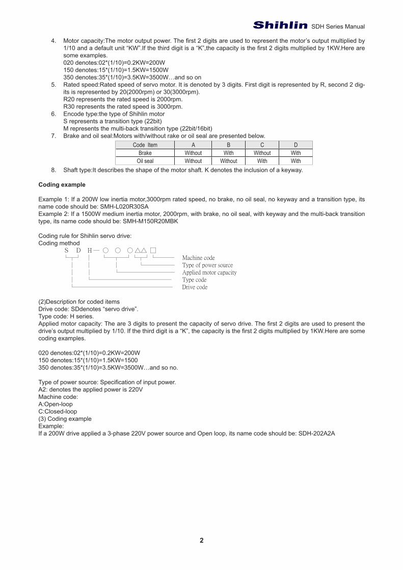
4. Motor capacity:The motor output power. The first 2 digits are used to represent the motor’s output multiplied by 1/10 and a default unit “KW”.If the third digit is a “K”,the capacity is the first 2 digits multiplied by 1KW.Here are some examples.020 denotes:02*(1/10)=0.2KW=200W150 denotes:15*(1/10)=1.5KW=1500W350 denotes:35*(1/10)=3.5KW=3500W…and so on
5. Rated speed:Rated speed of servo motor. It is denoted by 3 digits. First digit is represented by R, second 2 dig-its is represented by 20(2000rpm) or 30(3000rpm).R20 represents the rated speed is 2000rpm.R30 represents the rated speed is 3000rpm.
6. Encode type:the type of Shihlin motor S represents a transition type (22bit)M represents the multi-back transition type (22bit/16bit)
7. Brake and oil seal:Motors with/without rake or oil seal are presented below.Code Item A B C D
Brake Without With Without WithOil seal Without Without With With
8. Shaft type:It describes the shape of the motor shaft. K denotes the inclusion of a keyway.
Coding example
Example 1: If a 200W low inertia motor,3000rpm rated speed, no brake, no oil seal, no keyway and a transition type, its name code should be: SMH-L020R30SAExample 2: If a 1500W medium inertia motor, 2000rpm, with brake, no oil seal, with keyway and the multi-back transition type, its name code should be: SMH-M150R20MBK
Coding rule for Shihlin servo drive:Coding method S D H ─ ○ ○ ○ △△ □ └┬┘ │ └─┬─┘└┬┘└─── Machine code │ │ │ └───── Type of power source │ │ └───────── Applied motor capacity │ └───────────── Type code └──────────────── Drive code
(2)Description for coded itemsDrive code: SDdenotes “servo drive”.Type code: H series.Applied motor capacity: The are 3 digits to present the capacity of servo drive. The first 2 digits are used to present the drive’s output multiplied by 1/10. If the third digit is a “K”, the capacity is the first 2 digits multiplied by 1KW.Here are some coding examples.
020 denotes:02*(1/10)=0.2KW=200W 150 denotes:15*(1/10)=1.5KW=1500 350 denotes:35*(1/10)=3.5KW=3500W…and so no.
Type of power source: Specification of input power.A2: denotes the applied power is 220VMachine code:A:Open-loopC:Closed-loop(3) Coding exampleExample: If a 200W drive applied a 3-phase 220V power source and Open loop, its name code should be: SDH-202A2A
3
Chapter 1.
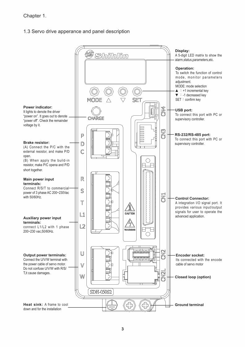
1.3 Servo drive apperance and panel description
Power indicator:It lights to denote the driver “power on”. It goes out to denote “power off”. Check the remainder voltage by it.
Brake resistor: (A) Connect the P/C with the external resistor, and make P/D open.(B) When apply the bui ld- in resistor, make P/C opena and P/D short together.
Main power input terminals: Connect R/S/T to commercial power of 3 phase AC 200~230Vac with 50/60Hz.
Auxiliary power input terminals:connect L1/L2 with 1 phase 200~230 vac,50/60Hz.
Output power terminals: Connect the U/V/W terminal with the power cable of servo motor. Do not confuse U/V/W with R/S/T,it cause damages.
Heat sink: A frame to cool down and for the installation
Display: A 5-digit LED matrix to show the alarm,status,parameters,etc.
Operation: To switch the function of control m o d e , m o n i t o r p a r a m e t e r s adjustment.MODE: mode selection▲:+1 incremental key▼:-1 decreased keySET:confirm key
USB port: To connect this port with PC or supervisory controller.
RS-232/RS-485 port: To connect this port with PC or supervisory controller.
Control Connector: A integration I/O signal port. It provides various input/output signals for user to operate the advanced application.
Encoder socket: Its connected with the encode cable of servo motor
Closed loop (option)
Ground terminal
4
SDH Series Manual
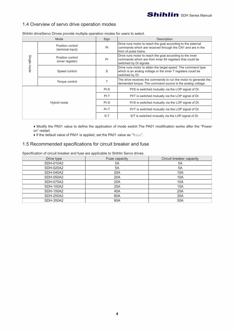
1.4 Overview of servo drive operation modes
Shihlin driveServo Drives provide multiple operation modes for users to select.Mode Sign Description
Single m
ode
Position control(terminal input) Pt
Drive runs motor to reach the goal according to the external commands which are received through the CN1 and are in the form of pulse trains.
Position control(inner register) Pr
Drive runs motor to reach the goal according to the inner commands which are from inner 64 registers that could be switched by DI signals.
Speed control SDrive runs motor to attain the target speed. The command type which is an analog voltage or the inner 7 registers could be switched by DI.
Torque control T The drive receives the commands to run the motor to generate the demanded torque. The command source is the analog voltage.
Hybrid mode
Pt-S Pt/S is switched mutually via the LOP signal of DI.
Pt-T Pt/T is switched mutually via the LOP signal of DI.
Pr-S Pr/S is switched mutually via the LOP signal of DI.
Pr-T Pr/T is switched mutually via the LOP signal of DI.
S-T S/T is switched mutually via the LOP signal of DI.
♦ Modify the PA01 value to define the application of mode switch.The PA01 modification works after the “Power on” restart.♦ If the default value of PA01 is applied, set the PA01 value as “1□□□”.
1.5 Recommended specifications for circuit breaker and fuse
Specification of circuit breaker and fuse are applicable to Shihlin Servo drives.Drive type Fuse capacity Circuit breaker capacity
SDH-010A2 5A 5ASDH-020A2 5A 5ASDH-040A2 20A 10ASDH-050A2 20A 10ASDH-075A2 20A 10ASDH-100A2 25A 15ASDH-150A2 40A 20ASDH-200A2 60A 30ASDH-350A2 80A 30A

5
Chapter 2.
2.Installation
2.1 Caution and storage methods
• Do not install the products on the inflammable matters or close to the inflammable matters.• Do not over tighten the wire between the drive and the motor.• Do not place heavy objects on the top of the drive.• Be sure to tight lock every screw when fixed the drive.• Install the drive at a location where could bear the weight of the drive.• Align the axle of the motor and the axle of the machinery device.• Inflammable objects or conductive objects are not allowed inside the drive.• Upgrade the diameter of the U/V/W wires and the encoder cable if the length between the drive and the motor
is over 20m.• Do not clog up the vent of the drive or breakdown may be occurred.• Do not drop or clash the drive.• Not try to run the drive which something has been damaged.• Please refer to section 10.1 and 10.3 for drive and motor storage details.
2.2 The environment conditions of installation
The ambient temperature suitable for Shihlin drive is between 0℃ and 55℃ . If the ambient temperature is higher than 45 ℃ , The installation place with good ventilation or air conditioner is necessary. For a long-time operation, place the drive in an environment with temperature below 45 ℃ to ensure the reliability of the drive. If the product is installed in a distributor, make sure that its size and ventilation condition. To prevent from over-heat of the electronic components inside it. Make sure that mechanical vibration will not affect the electronic devices of the distributor. In addition, the use of Shihlin servo shall meet the following criteria:
• Locations with high-heating devices.• Locations without floating dust and metal particles.• Locations without corrosive, inflammable gas and liquid.• Locations without water drops,steam,dust or oil dust• Locations without electromagnetic interference.• Select a solid, biration-free location.
2.3 Installation direction and space
Attention:Follow the instruction of installation direction avoid the breakdown of drive. To provide a good ventilation by keeping sufficient space between the drive and other objects to avoid breakdown. Do not seal the vent of the drive or make the drive upside down during the installation to avoid breakdown.
Correct Incorrect

6
SDH Series Manual
Installation diagram:To achieve a lower wind resistance of the heat-dissipation fan for a more effective heat removal, follow the spacing recommendation for installing one or multiple AD drive Servo Drive.See the figure below.
30 mm(1.2 in.)or more
100m m(4.0 in.)or more
10 mm(0.4 in.) or more
30 mm(1.2 in.)or more
100m m(4.0 in.)or more
7
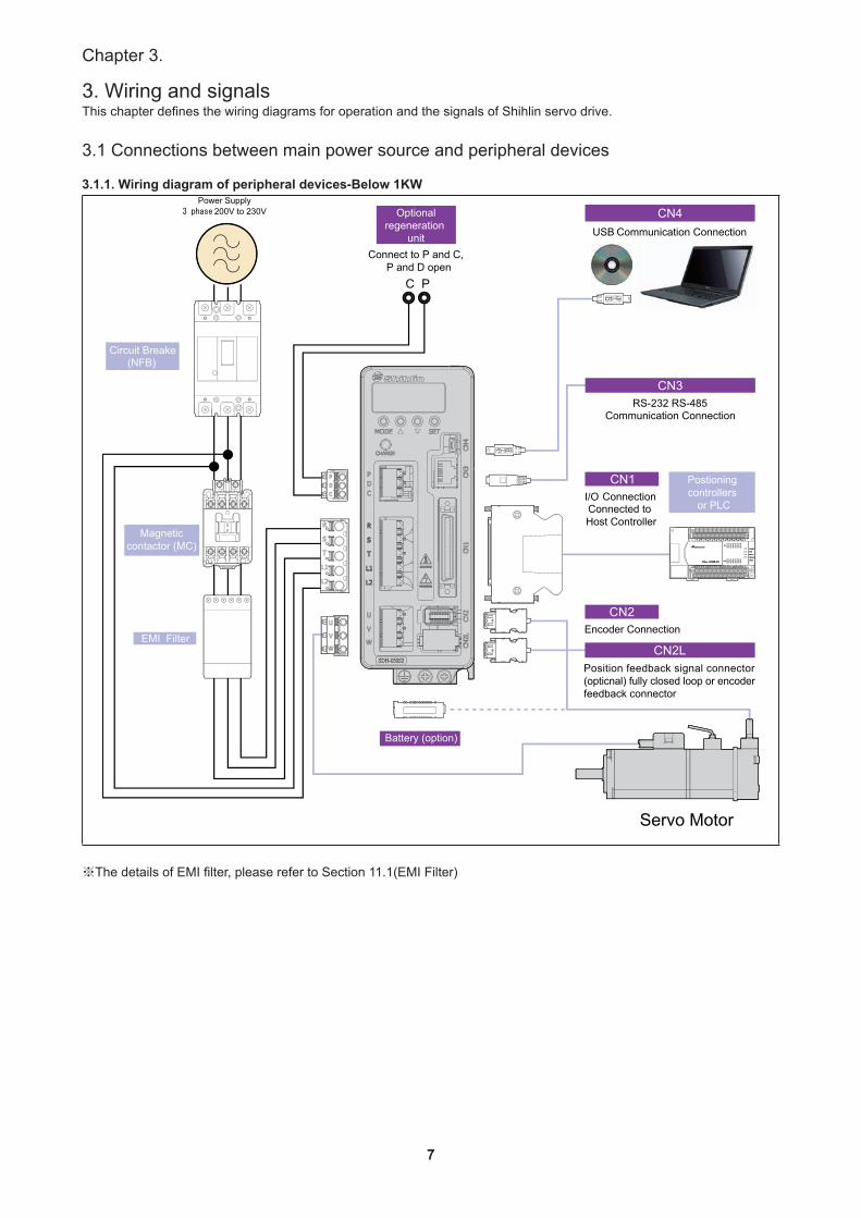
Chapter 3.
3. Wiring and signalsThis chapter defines the wiring diagrams for operation and the signals of Shihlin servo drive.
3.1 Connections between main power source and peripheral devices
3.1.1. Wiring diagram of peripheral devices-Below 1KW
※The details of EMI filter, please refer to Section 11.1(EMI Filter)
8
SDH Series Manual
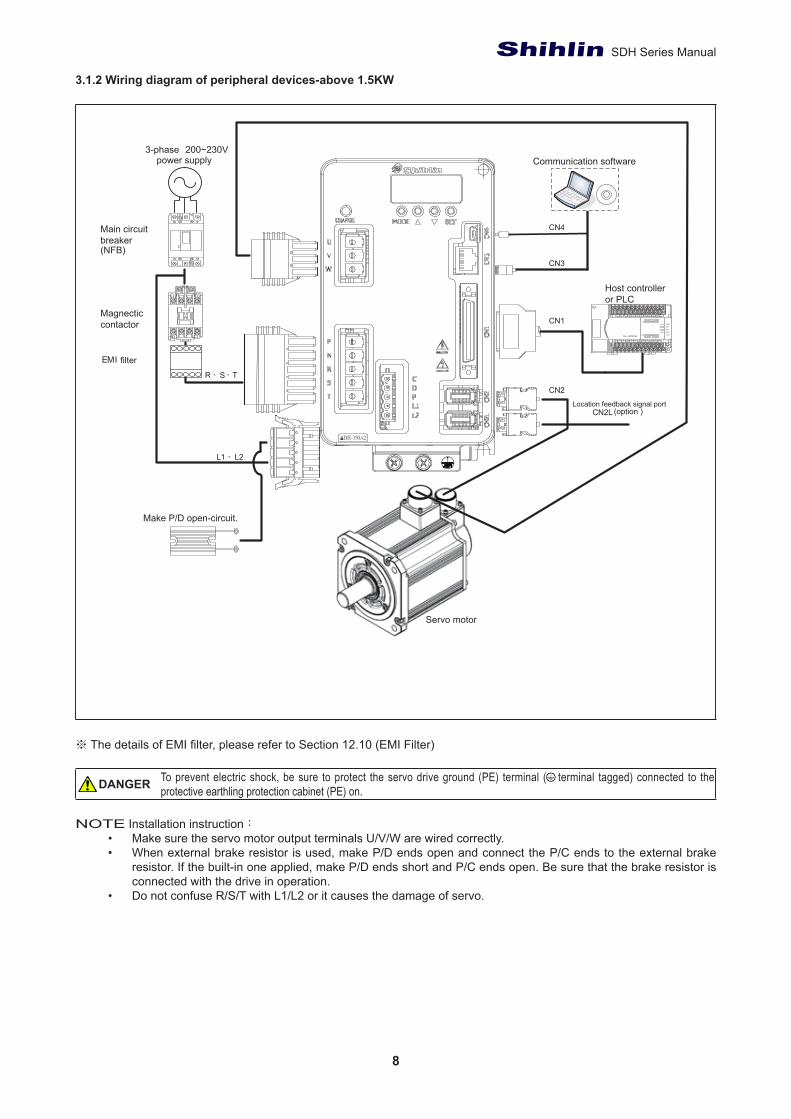
3.1.2 Wiring diagram of peripheral devices-above 1.5KW
※ The details of EMI filter, please refer to Section 12.10 (EMI Filter)
To prevent electric shock, be sure to protect the servo drive ground (PE) terminal ( terminal tagged) connected to the protective earthling protection cabinet (PE) on.
NOTE Installation instruction:
• Make sure the servo motor output terminals U/V/W are wired correctly.• When external brake resistor is used, make P/D ends open and connect the P/C ends to the external brake
resistor. If the built-in one applied, make P/D ends short and P/C ends open. Be sure that the brake resistor is connected with the drive in operation.
• Do not confuse R/S/T with L1/L2 or it causes the damage of servo.
DANGER
power supply3-phase 200~230V
Magnecticcontactor
LX10
N
Y10
CN3
CN2
CN1
Communication software
Host controller or PLC
Servo motor
CN4Main circuit breaker(NFB)
Make P/D open-circuit.
L1、 L2
R、S、T
CN2LLocation feedback signal port
(option )
EMI filter
9
Chapter 3.
3.1.3 Descriptions of drive’s connectors and terminal
Name Code DescriptionMain power input terminal R、S、T Connect to 3-phase AC power sourceControl power input terminal L1、L2 Connect to single phase AC power source
Power output terminal for motor U、V、W、
PE
Terminal code Wire colorU RedV WhiteW BlackPE Green
Brake resistor terminal P、D、C External resistor P/C ends connected to resistor and P/D end open.Built-in resistor P/D ends short together and P/C ends open
Ground terminal To connect the power ground with the motor ground.
P:main circuit (+)terminalN:main circuit(-)terminal P、N
When an active brake device is used dor 1.5KW or above, please connect the (+)terminal of it to the drive’s(P)terminal, the(-)terminal to the drive’s (N)terminal. The active brake device is usually applied when the huge regenerative power produced by the servo motor in heavy duty.
I/Connector CN1 Connect to the host controllerEncoder socket CN2 Connect to the encoder cable of servo motorLocation feedback signal port CN2L Connect to encoder or close loopRS-232/RS-485 port CN3 Connect to the COM PORT of PC.USBport CN4 Connect to the USB port of PC.
Confirm the items as follows when wiring:
• Keep the major power lines R/ST and U/V/W away from other signal lines at least 30cm.• Do not touch the major power lines until the charge indicator goes out. When “power off”, there is still a large
amount of electric charge in the aluminum capacitors inside the servo drive.• If a longer encoder cable is required, uses the twisted pairs cable and not to exceed 20m. Be sure to upgrade
the diameter of wires to avoid signals attenuated when the wire’s length greater than 20m.
Please insulate the connecting part of the power terminal to avoid electric shock.Make sure the servo and motor output terminals U/V/W are wired correctly. Otherwise it may cause shock.Make sure the servo motor output terminals is wired correctly.
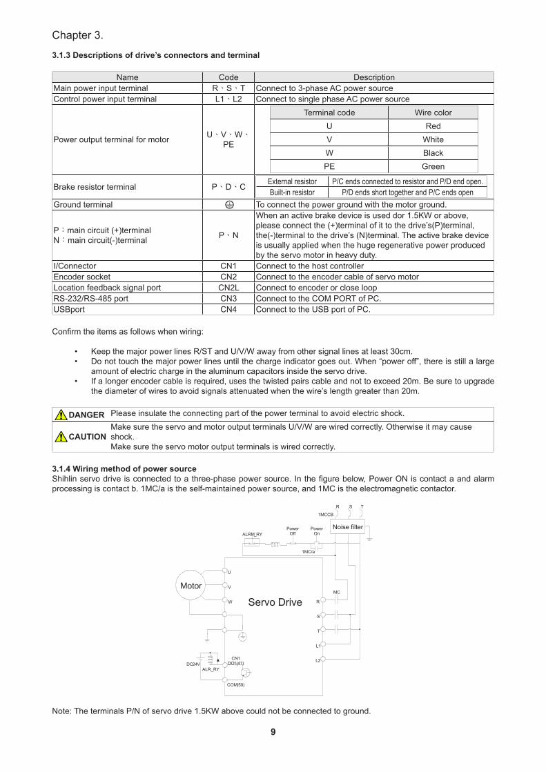
3.1.4 Wiring method of power source Shihlin servo drive is connected to a three-phase power source. In the figure below, Power ON is contact a and alarm processing is contact b. 1MC/a is the self-maintained power source, and 1MC is the electromagnetic contactor.
Motor
U
V
W
DC 24 V ALR_RY
CN 1DO 1 ( 41 )
COM ( 50 )
Servo Drive R
S
T
L 1
L 2
Noise filter
R S T
ALRM _ RY
1 MCCB
Power On
Power Off
1MC/a
MC
Note: The terminals P/N of servo drive 1.5KW above could not be connected to ground.
DANGER
CAUTION
10
SDH Series Manual
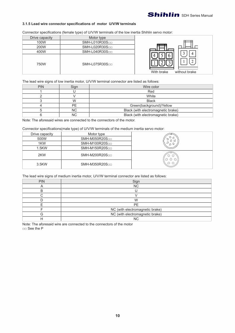
3.1.5 Lead wire connector specifications of motor U/V/W terminals
Connector specifications (female type) of U/V/W terminals of the low inertia Shihlin servo motor:Drive capacity Motor type
With brake without brake
100W SMH-L010R30S□□200W SMH-L020R30S□□400W SMH-L040R30S□□
750W SMH-L075R30S□□
The lead wire signs of low inertia motor, U/V/W terminal connector are listed as follows:PIN Sign Wire color1 U Red2 V White3 W Black4 PE Green(background)/Yellow5 NC Black (with electromagnetic brake)6 NC Black (with electromagnetic brake)
Note: The aforesaid wires are connected to the connectors of the motor.
Connector specifications(male type) of U/V/W terminals of the medium inertia servo motor:Drive capacity Motor type
500W SMH-M050R20S□□1KW SMH-M100R20S□□
1.5KW SMH-M150R20S□□
2KW SMH-M200R20S□□
3.5KW SMH-M350R20S□□
The lead wire signs of medium inertia motor, U/V/W terminal connector are listed as follows:PIN SignA NCB UC VD WE PEF NC (with electromagnetic brake)G NC (with electromagnetic brake)H NC
Note: The aforesaid wire are connected to the connectors of the motor□□ See the P
11
Chapter 3.
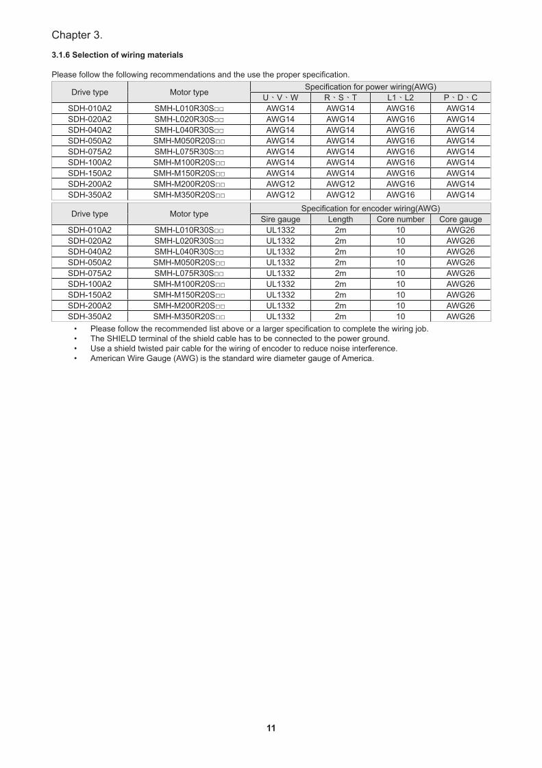
3.1.6 Selection of wiring materials
Please follow the following recommendations and the use the proper specification.
Drive type Motor type Specification for power wiring(AWG)U、V、W R、S、T L1、L2 P、D、C
SDH-010A2 SMH-L010R30S□□ AWG14 AWG14 AWG16 AWG14SDH-020A2 SMH-L020R30S□□ AWG14 AWG14 AWG16 AWG14SDH-040A2 SMH-L040R30S□□ AWG14 AWG14 AWG16 AWG14SDH-050A2 SMH-M050R20S□□ AWG14 AWG14 AWG16 AWG14SDH-075A2 SMH-L075R30S□□ AWG14 AWG14 AWG16 AWG14SDH-100A2 SMH-M100R20S□□ AWG14 AWG14 AWG16 AWG14SDH-150A2 SMH-M150R20S□□ AWG14 AWG14 AWG16 AWG14SDH-200A2 SMH-M200R20S□□ AWG12 AWG12 AWG16 AWG14SDH-350A2 SMH-M350R20S□□ AWG12 AWG12 AWG16 AWG14
Drive type Motor type Specification for encoder wiring(AWG)Sire gauge Length Core number Core gauge
SDH-010A2 SMH-L010R30S□□ UL1332 2m 10 AWG26SDH-020A2 SMH-L020R30S□□ UL1332 2m 10 AWG26SDH-040A2 SMH-L040R30S□□ UL1332 2m 10 AWG26SDH-050A2 SMH-M050R20S□□ UL1332 2m 10 AWG26SDH-075A2 SMH-L075R30S□□ UL1332 2m 10 AWG26SDH-100A2 SMH-M100R20S□□ UL1332 2m 10 AWG26SDH-150A2 SMH-M150R20S□□ UL1332 2m 10 AWG26SDH-200A2 SMH-M200R20S□□ UL1332 2m 10 AWG26SDH-350A2 SMH-M350R20S□□ UL1332 2m 10 AWG26
• Please follow the recommended list above or a larger specification to complete the wiring job.• The SHIELD terminal of the shield cable has to be connected to the power ground.• Use a shield twisted pair cable for the wiring of encoder to reduce noise interference.• American Wire Gauge (AWG) is the standard wire diameter gauge of America.
12
SDH Series Manual
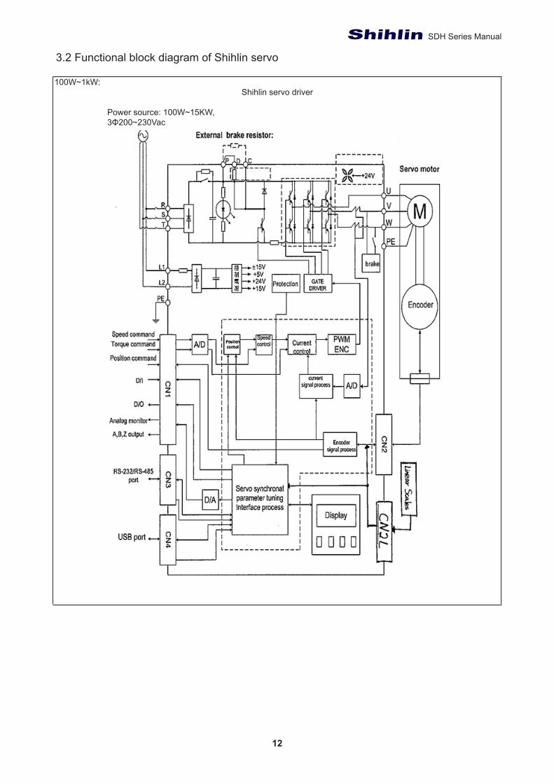
3.2 Functional block diagram of Shihlin servo
100W~1kW:Shihlin servo driver
Power source: 100W~15KW,3Φ200~230Vac
13
Chapter 3.
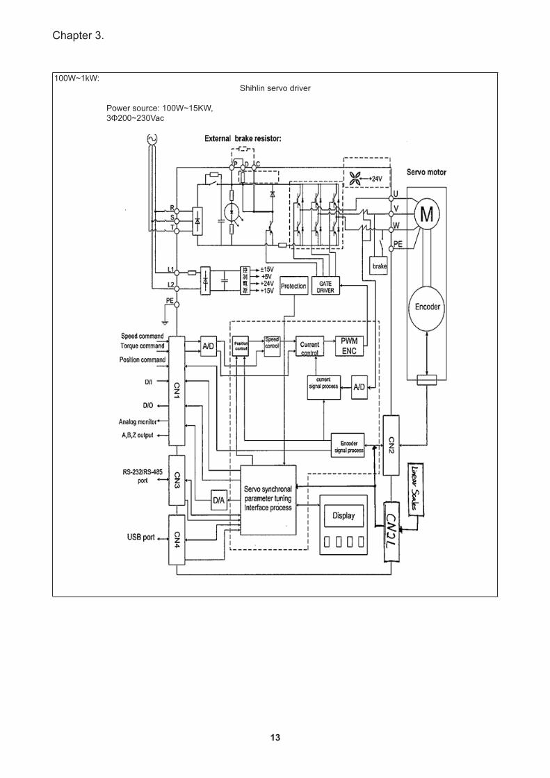
100W~1kW:Shihlin servo driver
Power source: 100W~15KW,3Φ200~230Vac
14
SDH Series Manual
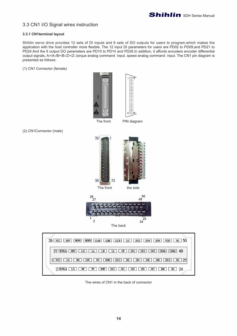
3.3 CN1 I/O Signal wires instruction
3.3.1 CN1terminal layout
Shihlin servo drive provides 12 sets of DI inputs and 6 sets of DO outputs for users to program,which makes the application with the host controller more flexible. The 12 input DI parameters for users are PD02 to PD09,and PD21 to PD24.And the 6 output DO parameters are PD10 to PD14 and PD26.In addition, it affords encoders encoder differential output signals, A+/A-/B+/B-/Z+/Z-,torque analog command input, speed analog command input. The CN1 pin diagram is presented as follows:
(1) CN1 Connector (female)
The front PIN diagram
(2) CN1Connector (male)
The front the side
The back
The wires of CN1 in the back of connector
15
Chapter 3.
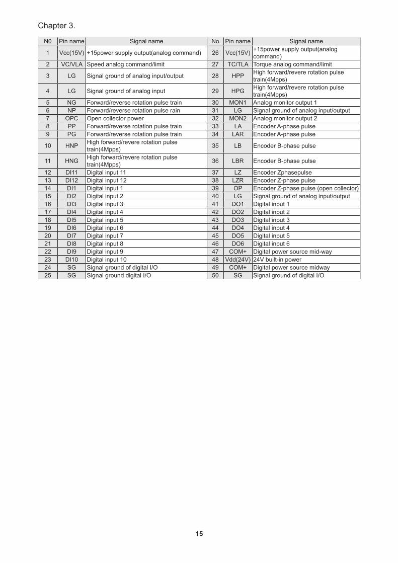
N0 Pin name Signal name No Pin name Signal name
1 Vcc(15V) +15power supply output(analog command) 26 Vcc(15V) +15power supply output(analog command)
2 VC/VLA Speed analog command/limit 27 TC/TLA Torque analog command/limit
3 LG Signal ground of analog input/output 28 HPP High forward/revere rotation pulse train(4Mpps)
4 LG Signal ground of analog input 29 HPG High forward/revere rotation pulse train(4Mpps)
5 NG Forward/reverse rotation pulse train 30 MON1 Analog monitor output 16 NP Forward/reverse rotation pulse rain 31 LG Signal ground of analog input/output7 OPC Open collector power 32 MON2 Analog monitor output 28 PP Forward/reverse rotation pulse train 33 LA Encoder A-phase pulse9 PG Forward/reverse rotation pulse train 34 LAR Encoder A-phase pulse
10 HNP High forward/revere rotation pulse train(4Mpps) 35 LB Encoder B-phase pulse
11 HNG High forward/revere rotation pulse train(4Mpps) 36 LBR Encoder B-phase pulse
12 DI11 Digital input 11 37 LZ Encoder Zphasepulse13 DI12 Digital input 12 38 LZR Encoder Z-phase pulse14 DI1 Digital input 1 39 OP Encoder Z-phase pulse (open collector)15 DI2 Digital input 2 40 LG Signal ground of analog input/output16 DI3 Digital input 3 41 DO1 Digital input 117 DI4 Digital input 4 42 DO2 Digital input 218 DI5 Digital input 5 43 DO3 Digital input 319 DI6 Digital input 6 44 DO4 Digital input 420 DI7 Digital input 7 45 DO5 Digital input 521 DI8 Digital input 8 46 DO6 Digital input 622 DI9 Digital input 9 47 COM+ Digital power source mid-way23 DI10 Digital input 10 48 Vdd(24V) 24V built-in power24 SG Signal ground of digital I/O 49 COM+ Digital power source midway25 SG Signal ground digital I/O 50 SG Signal ground of digital I/O
16
SDH Series Manual
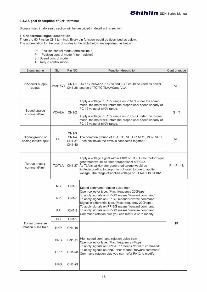
3.3.2 Signal description of CN1 terminal
Signals listed in aforesaid section will be described in detail in this section.
1. CN1 terminal signal descriptionThere are 50 Pins on CN1 terminal. Every pin function would be described as below:The abbreviation for the control modes in the table below are explained as below:
Pt :Position control mode (terminal input) Pr :Position control mode (inner register) S:Speed control mode T:Torque control mode
Signal name Sign Pin NO Function description Control mode
+15power supply output Vcc(15V) CN1-1
CN1-26DC 15V between+15Vcc and LC.It could be used as power source of TC,TC,TLA,VCand VLA. ALL
Speed analog command/limit VC/VLA CN1-2
Apply a voltage in ±10V range on VC-LG under the speed mode, the motor will rotate the proportional speed linearly of PC 12 value at ±10V range.
Apply a voltage in ±10V range on VLC-LG under the torque mode, the motor will rotate the proportional speed linearly of PC 12 value at ±10V range.
S、T
Signal ground of analog input/output LG
CN1-3CN1-4CN1-31CN1-40
The common ground of TLA, TC, VC, OP, MO1, MO2, VCC. Each pin inside the drive is connected together. ALL
Torque analog command/limit TC/TLA CN1-27
Apply a voltage signal within ±10V on TC-LG,the motortorque generated would be linear proportional of PC13.As TLA is valid,motor generated torque would be limitedaccording to proportion of rated torque to applied voltage. The range of applied voltage on TLA-LG IS 0±10V
Pt、Pr、S
Forward/reverse rotation pulse train
NG CN1-5 Speed command rotation pulse trainOpen collector type: (Max. frequency 200Kpps)To apply signals on PP-SG means “forward command”To apply signals on PP-SG means “reverse command”Signal in differential type. (Max. frequency 200Kpps)To apply signals on PP-SG means “forward commandTo apply signals on PP-SG means “reverse commandCommand rotation plus you can refer PA12 to modify
Pt
NP CN1-6
PP CN1-8
PG CN1-9
HNP CN1-10
High speed command rotation pulse trainOpen collector type: (Max. frequency 4Mpps)To apply signals on HPG-HPP means “forward command”To apply signals on HNG-HNP means “forward command”Command rotation plus you can refer PA12 to modify
HNG CN1-11
HPP CN1-28
HPG CN1-29
17
Chapter 3.
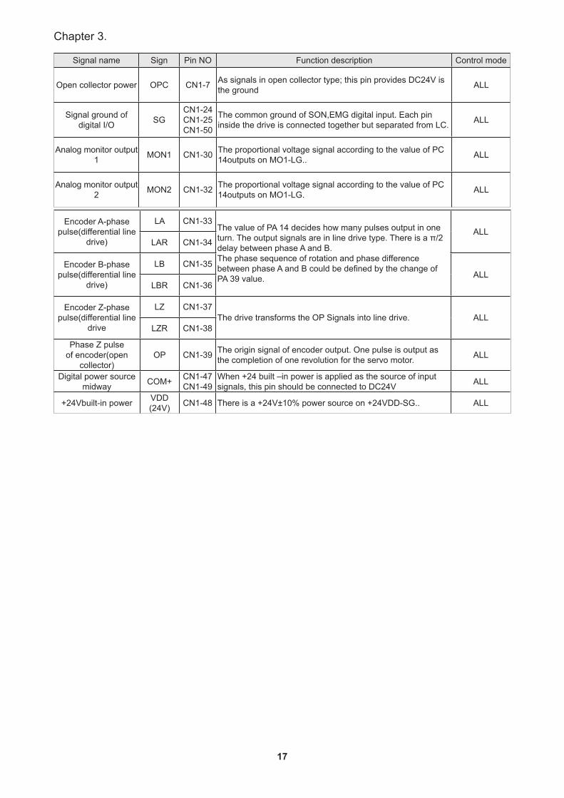
Signal name Sign Pin NO Function description Control mode
Open collector power OPC CN1-7 As signals in open collector type; this pin provides DC24V is the ground ALL
Signal ground of digital I/O SG
CN1-24CN1-25CN1-50
The common ground of SON,EMG digital input. Each pin inside the drive is connected together but separated from LC. ALL
Analog monitor output 1 MON1 CN1-30 The proportional voltage signal according to the value of PC
14outputs on MO1-LG.. ALL
Analog monitor output 2 MON2 CN1-32 The proportional voltage signal according to the value of PC
14outputs on MO1-LG. ALL
Encoder A-phase pulse(differential line
drive)
LA CN1-33The value of PA 14 decides how many pulses output in one turn. The output signals are in line drive type. There is a π/2 delay between phase A and B.The phase sequence of rotation and phase difference between phase A and B could be defined by the change of PA 39 value.
ALLLAR CN1-34
Encoder B-phase pulse(differential line
drive)
LB CN1-35ALL
LBR CN1-36
Encoder Z-phase pulse(differential line
drive
LZ CN1-37The drive transforms the OP Signals into line drive. ALL
LZR CN1-38
Phase Z pulse of encoder(open
collector)OP CN1-39 The origin signal of encoder output. One pulse is output as
the completion of one revolution for the servo motor. ALL
Digital power source midway COM+ CN1-47
CN1-49When +24 built –in power is applied as the source of input signals, this pin should be connected to DC24V ALL
+24Vbuilt-in power VDD(24V) CN1-48 There is a +24V±10% power source on +24VDD-SG.. ALL
18
SDH Series Manual
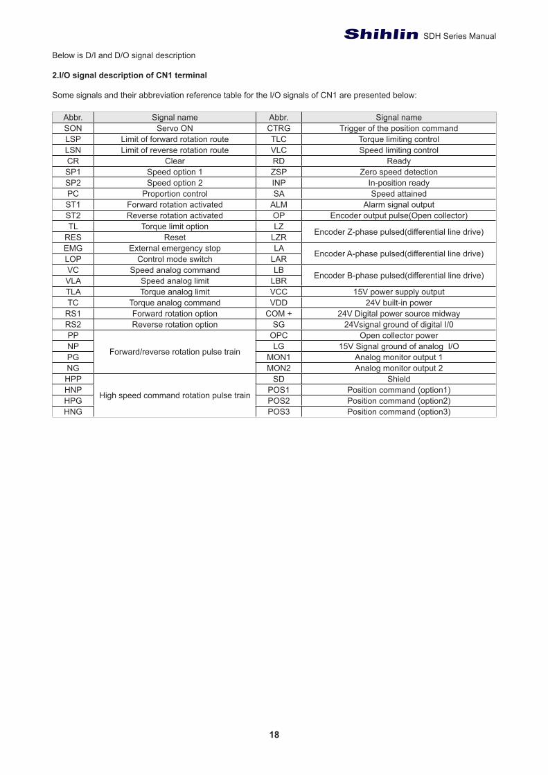
Below is D/I and D/O signal description
2.I/O signal description of CN1 terminal
Some signals and their abbreviation reference table for the I/O signals of CN1 are presented below:
Abbr. Signal name Abbr. Signal nameSON Servo ON CTRG Trigger of the position commandLSP Limit of forward rotation route TLC Torque limiting controlLSN Limit of reverse rotation route VLC Speed limiting controlCR Clear RD ReadySP1 Speed option 1 ZSP Zero speed detectionSP2 Speed option 2 INP In-position readyPC Proportion control SA Speed attainedST1 Forward rotation activated ALM Alarm signal outputST2 Reverse rotation activated OP Encoder output pulse(Open collector)TL Torque limit option LZ Encoder Z-phase pulsed(differential line drive)RES Reset LZR
EMG External emergency stop LA Encoder A-phase pulsed(differential line drive)LOP Control mode switch LARVC Speed analog command LB Encoder B-phase pulsed(differential line drive)VLA Speed analog limit LBRTLA Torque analog limit VCC 15V power supply outputTC Torque analog command VDD 24V built-in power
RS1 Forward rotation option COM + 24V Digital power source midwayRS2 Reverse rotation option SG 24Vsignal ground of digital I/0PP
Forward/reverse rotation pulse train
OPC Open collector powerNP LG 15V Signal ground of analog I/OPG MON1 Analog monitor output 1NG MON2 Analog monitor output 2HPP
High speed command rotation pulse train
SD ShieldHNP POS1 Position command (option1)HPG POS2 Position command (option2)HNG POS3 Position command (option3)

19
Chapter 3.
3.DI and DO signal description
Input DIThere are 39 signal functions could be assigned to the particular DI pin by the modification of parameter. As the below sheet:
Signal function Sign Factions/Applications description Control mode
Servo ON SON Power on the drive and make SON short-circuit to ready (the shaft is locked). Make SON open-circuit to release (The shit is rotatable). A virtual”Servo ON” could be achieved by the PD01. ALL
Reset RESA short-circuit duration over 50Ms on RES would recover from an abnormal alarm status. Some abnormal cases would not be recovered (refer to section 11.1). Set the PD20 as PD20as XXX1, the function of reset would not work.
ALL
Proportion control PC
A short-circuit on PC would switch the proportion-integral controller to the proportion controller (speed control). When motor in static, it outputs torque to resist the external disturbance which even only 1 pulse revolution. Once the position is done, to prevent from unnecessary jitter of motor shaft, please switch to the proportion controller.
Pt,Pr,S
Torque limit option TL Turn TL-SG on the make analog torque limit (TLA) valid.Fordetails, refer to section TL1. Pt,Pr,S
Inner torque limit option TL1
Turn TL1- SG on to make inner torque limit 2 valid.I/S Effect torque limit valueTL1 TL
0 0 Parameter PA05
0 1 TLA > Parameter PA05 => Parameter PA05TLA < Parameter PA05 => TLA
1 0 Parameter PC25> Parameter PA05 => Parameter PA05Parameter PC25< Parameter PA05 => Parameter PC25
1 1 TLA > Parameter PC25 => Parameter PC25TLA < Parameter PC25 =>TLA
ALL
Speed option 1 SP1
Speed control mode. Used to select the speed command.When using SP3, make it usable by making the setting.
Setting Input signals Speed commandSP3 SP2 SP1When speed option(SP3)Is not used.
(initial status)
0 0 Speed analog command(VC)0 1 Inner speed command 11 0 Inner speed command 21 1 Inner speed command 3
When speed option (SP3 is made valid.
0 0 0 Speed analog command (VC)0 0 1 Inner speed command 10 1 0 Inner speed command 20 1 1 Inner speed command 31 0 0 Inner speed command 41 0 1 Inner speed command 51 1 0 Inner speed command 61 1 1 Inner speed command 7
Torque control mode. Used to select the limit speed for operation.
Setting Input signals Speed commandSP3 SP2 SP1When speed option(SP3)
Is not used. (initial status)
0 0 Speed analog command(VC)0 1 Inner speed command 11 0 Inner speed command 21 1 Inner speed command 3
When speed option(SP3 is made
valid
0 0 0 Speed analog command (VC)0 0 1 Inner speed command 10 1 0 Inner speed command 20 1 1 Inner speed command 31 0 0 Inner speed command 41 0 1 Inner speed command 51 1 0 Inner speed command 61 1 1 Inner speed command 7
S,T
Speed option 2 SP2
Speed option 3 SP3
20
SDH Series Manual
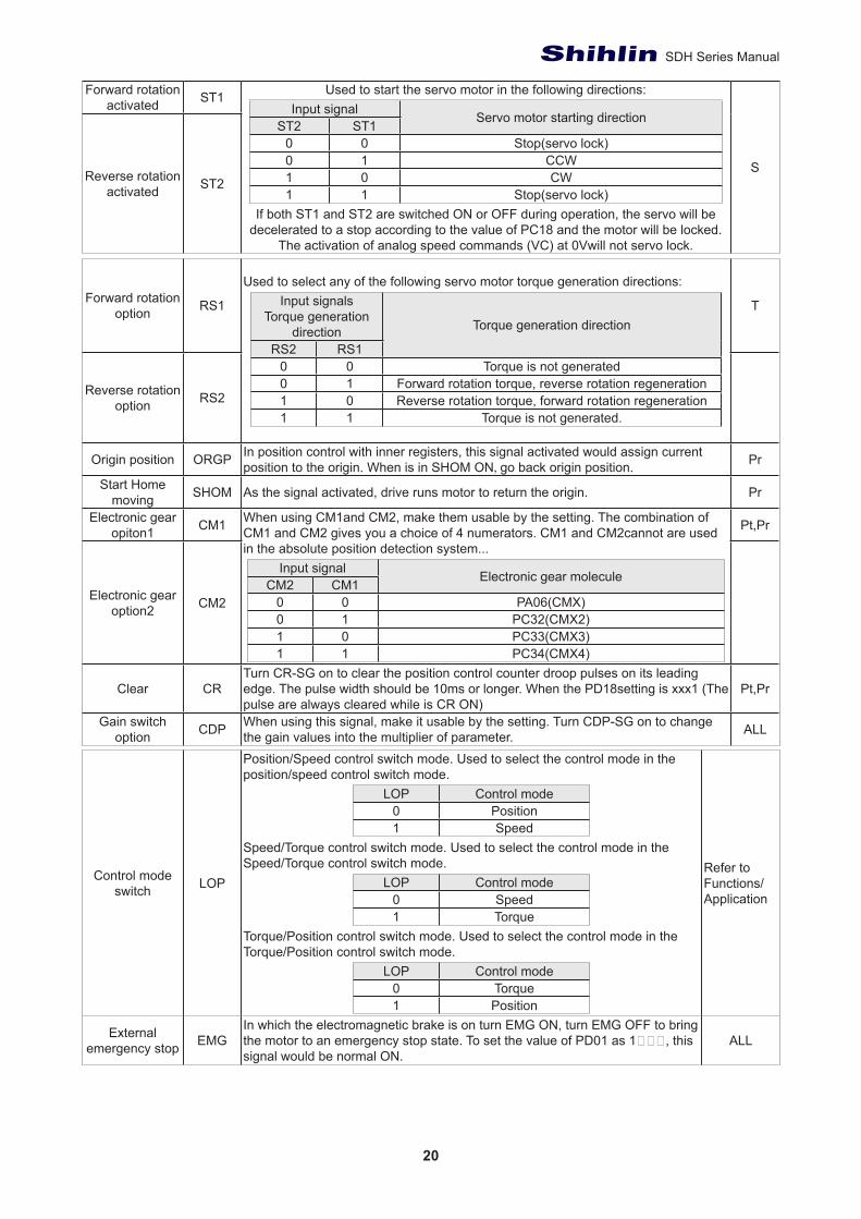
Forward rotation activated ST1 Used to start the servo motor in the following directions:
Input signal Servo motor starting directionST2 ST10 0 Stop(servo lock)0 1 CCW1 0 CW1 1 Stop(servo lock)
If both ST1 and ST2 are switched ON or OFF during operation, the servo will be decelerated to a stop according to the value of PC18 and the motor will be locked.
The activation of analog speed commands (VC) at 0Vwill not servo lock.
SReverse rotation activated ST2
Forward rotation option RS1
Used to select any of the following servo motor torque generation directions:Input signals
Torque generation direction Torque generation direction
RS2 RS10 0 Torque is not generated0 1 Forward rotation torque, reverse rotation regeneration1 0 Reverse rotation torque, forward rotation regeneration1 1 Torque is not generated.
T
Reverse rotation option RS2
Origin position ORGP In position control with inner registers, this signal activated would assign current position to the origin. When is in SHOM ON, go back origin position. Pr
Start Home moving SHOM As the signal activated, drive runs motor to return the origin. Pr
Electronic gear opiton1 CM1 When using CM1and CM2, make them usable by the setting. The combination of
CM1 and CM2 gives you a choice of 4 numerators. CM1 and CM2cannot are used in the absolute position detection system...
Input signal Electronic gear moleculeCM2 CM10 0 PA06(CMX)0 1 PC32(CMX2)1 0 PC33(CMX3)1 1 PC34(CMX4)
Pt,Pr
Electronic gear option2 CM2
Clear CRTurn CR-SG on to clear the position control counter droop pulses on its leading edge. The pulse width should be 10ms or longer. When the PD18setting is xxx1 (The pulse are always cleared while is CR ON)
Pt,Pr
Gain switch option CDP When using this signal, make it usable by the setting. Turn CDP-SG on to change
the gain values into the multiplier of parameter. ALL
Control mode switch LOP
Position/Speed control switch mode. Used to select the control mode in the position/speed control switch mode.
LOP Control mode0 Position1 Speed
Speed/Torque control switch mode. Used to select the control mode in the Speed/Torque control switch mode.
LOP Control mode0 Speed1 Torque
Torque/Position control switch mode. Used to select the control mode in the Torque/Position control switch mode.
LOP Control mode0 Torque1 Position
Refer to Functions/Application
External emergency stop EMG
In which the electromagnetic brake is on turn EMG ON, turn EMG OFF to bring the motor to an emergency stop state. To set the value of PD01 as 1口口口, this signal would be normal ON.
ALL
21
Chapter 3.
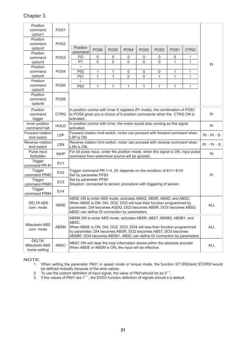
Position command option1
POS1
Position command POS6 POS5 POS4 POS3 POS2 POS1 CTRG
PO 0 0 0 0 0 0 ↑P1 0 0 0 0 0 1 ↑~
P50 1 1 0 0 0 1 ↑P51 1 1 0 0 1 1 ↑
~P63 1 1 1 1 1 1 ↑
Pr
Position command option2
POS2
Position command option3
POS3
Position command option4
POS4
Position command option5
POS5
Position command option6
POS6
Position command
triggerCTRG
In position control with inner 6 registers (Pr mode), the combination of POS1 to POS6 gives you a choice of 6 position commands when the CTRG ON is activated..
Pr
Inner position command halt HOLD In position control with inner, the motor would stop running as this signal
activated. Pr
Forward rotation limit switch LSP Forward rotation limit switch, motor can proceed with forward command when
LSP is ON Pt、Pr、S
Reverse rotation limit switch LSN Reverse rotation limit switch, motor can proceed with reverse command when
LSN is ON. Pt 、Pr、S
Pulse input forbidden INHP For bit pulse input, under the position mode, when this signal is ON, input pulse
command from exterminal source will be ignored. Pt
Trigger command PR #1 EV1
Trigger command PR 1~4, DI: depends on the condition of EV1~EV4Set by parameter PF83Set by parameter PF84Situation: connected to sensor, procedure with triggering of sensor.
PrTrigger
command PR#2 EV2
Trigger command PR#3 EV3
Trigger command PR#4 EV4
DELTA ABS com. mode ABSE
ABSE ON to enter ABS mode, activates ABSQ, ABSR, ABSD, and ABSC.When ABSE is ON: DI4, DO2, DO3 will lose their function programmed by parameter; DI4 becomes ASDQ, DO2 becomes ABSR, DO3 becomes ABSD, ABSC can define DI connection by parameters.
ALL
Mitsubishi ABS com. mode ABSM
ABSM ON to enter ABS mode, activates ABSR, ABST, ABSB0, ABSB1, and ABSC.When ABSE is ON: DI4, DO2, DO3, DO4 will lose their function programmed by parameter; DI4 becomes ABSR, DO2 becomes ABST, DO3 becomes ABSB0, DO4 becomes ABSB1, ABSC can define DI connection by parameters.
ALL
DELTA/Mitsubishi ABS home setting
ABSC ABSC ON will clear the loop information stored within the absolute encoder. When ABSE or ABSM is ON, the input will be effective. ALL
NOTE:1. When setting the parameter PA01 in speed mode or torque mode, the function ST1/RS2and ST2/RS1would
be defined mutually because of the ame values.2. To use the custom definition of input signal, the value of PA01should be as 0¨¨¨. 3. If the values of PA01 are 1¨¨¨, the DI/DO function definition of signals should e a default.
22
SDH Series Manual
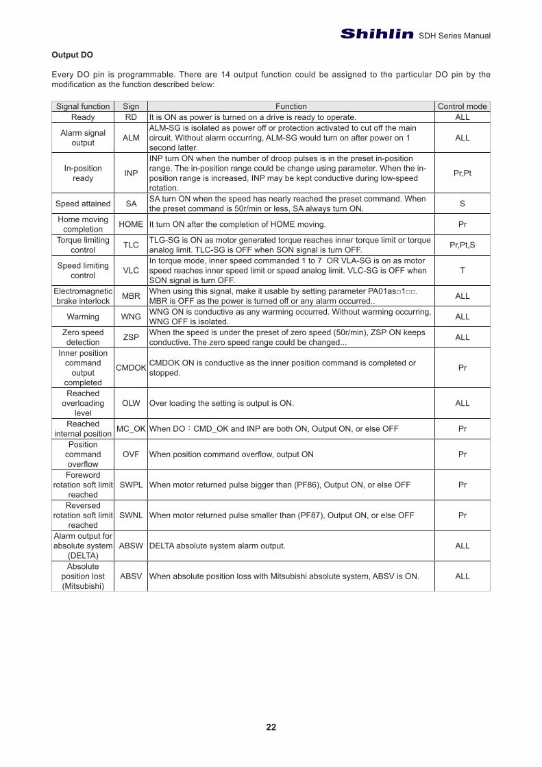
Output DO
Every DO pin is programmable. There are 14 output function could be assigned to the particular DO pin by the modification as the function described below:
Signal function Sign Function Control modeReady RD It is ON as power is turned on a drive is ready to operate. ALL
Alarm signal output ALM
ALM-SG is isolated as power off or protection activated to cut off the main circuit. Without alarm occurring, ALM-SG would turn on after power on 1 second latter.
ALL
In-position ready INP
INP turn ON when the number of droop pulses is in the preset in-position range. The in-position range could be change using parameter. When the in-position range is increased, INP may be kept conductive during low-speed rotation.
Pr,Pt
Speed attained SA SA turn ON when the speed has nearly reached the preset command. When the preset command is 50r/min or less, SA always turn ON. S
Home moving completion HOME It turn ON after the completion of HOME moving. Pr
Torque limiting control TLC TLG-SG is ON as motor generated torque reaches inner torque limit or torque
analog limit. TLC-SG is OFF when SON signal is turn OFF. Pr,Pt,S
Speed limiting control VLC
In torque mode, inner speed commanded 1 to 7 OR VLA-SG is on as motor speed reaches inner speed limit or speed analog limit. VLC-SG is OFF when SON signal is turn OFF.
T
Electromagnetic brake interlock MBR When using this signal, make it usable by setting parameter PA01as□1□□.
MBR is OFF as the power is turned off or any alarm occurred.. ALL
Warming WNG WNG ON is conductive as any warming occurred. Without warming occurring, WNG OFF is isolated. ALL
Zero speed detection ZSP When the speed is under the preset of zero speed (50r/min), ZSP ON keeps
conductive. The zero speed range could be changed... ALL
Inner position command
output completed
CMDOK CMDOK ON is conductive as the inner position command is completed or stopped. Pr
Reached overloading
levelOLW Over loading the setting is output is ON. ALL
Reached internal position MC_OK When DO:CMD_OK and INP are both ON, Output ON, or else OFF Pr
Position command overflow
OVF When position command overflow, output ON Pr
Foreword rotation soft limit
reachedSWPL When motor returned pulse bigger than (PF86), Output ON, or else OFF Pr
Reversed rotation soft limit
reached SWNL When motor returned pulse smaller than (PF87), Output ON, or else OFF Pr
Alarm output for absolute system
(DELTA)ABSW DELTA absolute system alarm output. ALL
Absolute position lost (Mitsubishi)
ABSV When absolute position loss with Mitsubishi absolute system, ABSV is ON. ALL
23
Chapter 3.
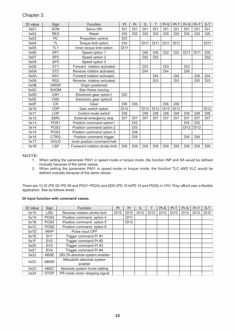
DI value Sign Function Pt Pr S T Pt-S Pt-T Pr-S Pr-T S-T0x01 SON Servo ON DI1 DI1 DI1 DI1 DI1 DI1 DI1 DI1 DI10x02 RES Reset DI5 DI5 DI5 DI5 DI5 DI5 DI5 DI5 DI50x03 PC Proportion control DI30x04 TL Torque limit option DI4 DI11 DI11 DI11 DI11 DI110x05 TL1 Inner torque limit option DI110x06 SP1 Speed option 1 DI6 DI6 DI2 DI2 DI11 DI11 DI60x07 SP2 Speed option 2 DI2 DI2 DI20x08 SP3 Speed option 30x09 ST1 Forward rotation activated DI3 DI3 DI30x0A ST2 Reverse rotation activated. DI4 DI4 DI60x0A RS1 Forward rotation activated. DI4 DI4 DI6 DI40x09 RS2 Reverse rotation activated DI3 DI3 DI3 DI30x0B ORGP Origin positioned0x0C SHOM Star Home moving0x0D CM1 Electronic gear option1 DI20x0E CM2 Electronic gear option20x0F CR Clear DI6 DI6 DI6 DI60x10 CDP Gain switch option DI12 DI12 DI12 DI12 DI12 DI120x11 LOP Control mode switch DI8 DI8 DI8 DI8 DI8 DI8 DI8 DI80x12 EMG External emergency stop DI7 DI7 DI7 DI7 DI7 DI7 DI7 DI7 DI70x13 POS1 Position command option1 DI2 DI2 DI20x14 POS2 Position command option 2 DI3 DI12 DI120x15 POS3 Position command option 3 DI80x16 CTRG Position command trigger DI4 DI4 DI40x17 HOLD Inner position command halt0x18 LSP Foreword rotation stroke limit DI9 DI9 DI9 DI9 DI9 DI9 DI9 DI9 DI9
NOTE:1. When setting the parameter PA01 in speed mode or torque mode, the function INP and SA would be defined
mutually because of the same values.2. When setting the parameter PA01 in speed mode or torque mode, the function TLC AND VLC would be
defined mutually because of the same values.
There are 12 DI (PD 02~PD 09 and PD21~PD24) and 6DO (PD 10 toPD 14 and PD26) in CN1.They afford user a flexible application. See as follows sheet.
DI input function with command values.
DI Value Sign Function Pt Pr S T Pt-S Pt-T Pr-S Pr-T S-T0x19 LSN Reverse rotation stroke limit DI10 DI10 DI10 DI10 DI10 DI10 DI10 DI10 DI100x1A POS4 Position command option 4 DI110x1B POS5 Position command option 5 DI120x1C POS6 Position command option 60x1D INHP Pulse input OFF0x1E EV1 Trigger command Pr #10x1F EV2 Trigger command Pr #20x20 EV3 Trigger command Pr #30x21 EV4 Trigger command Pr #40x22 ABSE DELTA absolute system enabler
0x22 ABSM Mitsubishi absolute system enabler
0x23 ABSC Absolute system home setting0x24 STOP PR mode motor stopping signal

24
SDH Series Manual
DO output function with commanded values
Value Sign Function Pt Pr S T Pt-S Pt-T Pr-S Pr-T S-T0x01 RD Ready DO5 DO5 DO5 DO5 DO5 DO5 DO5 DO5 DO50x02 ALM Trouble DO6 DO6 DO6 DO6 DO6 DO6 DO6 DO6 DO60x03 INP In-position ready DO1 DO1 DO1 DO1 DO1 DO10x03 SA Speed attained DO1 DO1 DO1 DO10x04 HOME Home return0x05 TLC Torque limiting control DO4 DO4 DO4 DO4 DO4 DO4 DO4 DO40x05 VLC Speed limiting control DO4 DO4 DO4 DO40X06 MBR Electromagnetic brake interlock DO3 DO3 DO30x07 WNG Warning DO3 DO1 DO3 DO30x08 ZSP Zero speed detection DO2 DO2 DO2 DO2 DO2 DO2 DO2 DO2 DO20x09 CMDOK Inner position command output completed DO3 DO3 DO30x0A OLW Reached over loading level0x0B MC_OK CMDOK and INP reached level0x0C OVF Position command overflow0x0D SWPL Output for forward position reached soft limit 0x0E SWNL Output for reverse position reached soft limit 0x0F ABSW Alarm output for absolute system (DELTA)0x10 ABSV Absolute position lost (Mitsubishi)
25
Chapter 3.
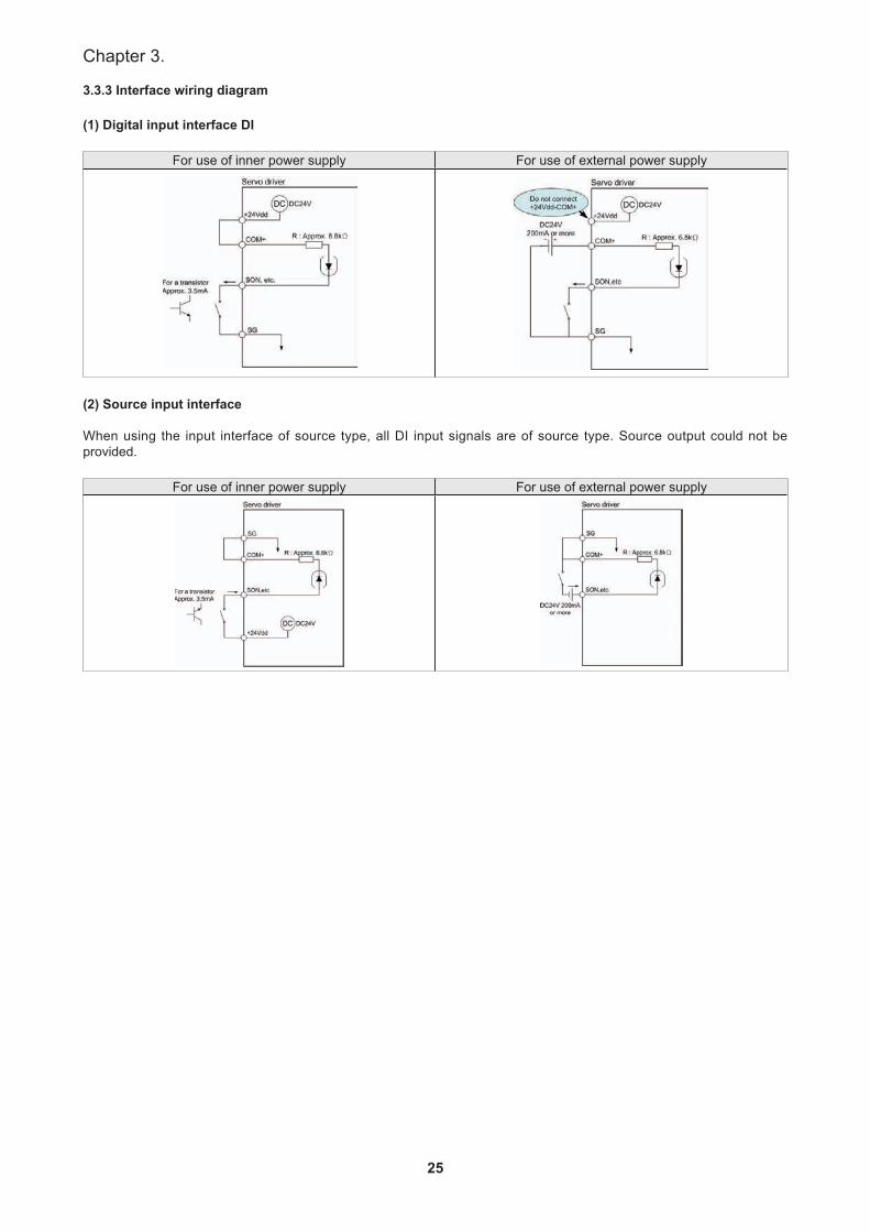
3.3.3 Interface wiring diagram
(1) Digital input interface DI
For use of inner power supply For use of external power supply
(2) Source input interface
When using the input interface of source type, all DI input signals are of source type. Source output could not be provided.
For use of inner power supply For use of external power supply

26
SDH Series Manual
(3) Digital output interface DO
Lamp, Relay or photo coupler could be driven. A diode for relay load or a suppressing resistor for lamp load is necessary. (Permissible current: 40mA or less, inrush current: 100mA or less)
Relay load for use of inner power supply Relay load for use of external power supply
Lamp load for use of inner power supply Lamp load for use of external power supply
(4) Speed analog command, torque analog command and MON1, MON2 analog output.
Input impedance 10KΩ~12KΩ/Output voltage ±10V.
Speed/torque analog command input MON1/MON2 analog monitor output
Note: VC/TC input voltage higher than 10V would damage the inner transistors of servo drive.
(5) Encoder output pulse
Output a pulse train signal in the open collector or differential Line Drive type, Open collector output could be obtained via the pin 39 (OP) of CN1. The maximum output current is 35mA.
Open collector type with OP output
Open collector type with photo coupler output
For different line drive system, the maximum output current is 20mA.
27
Chapter 3.
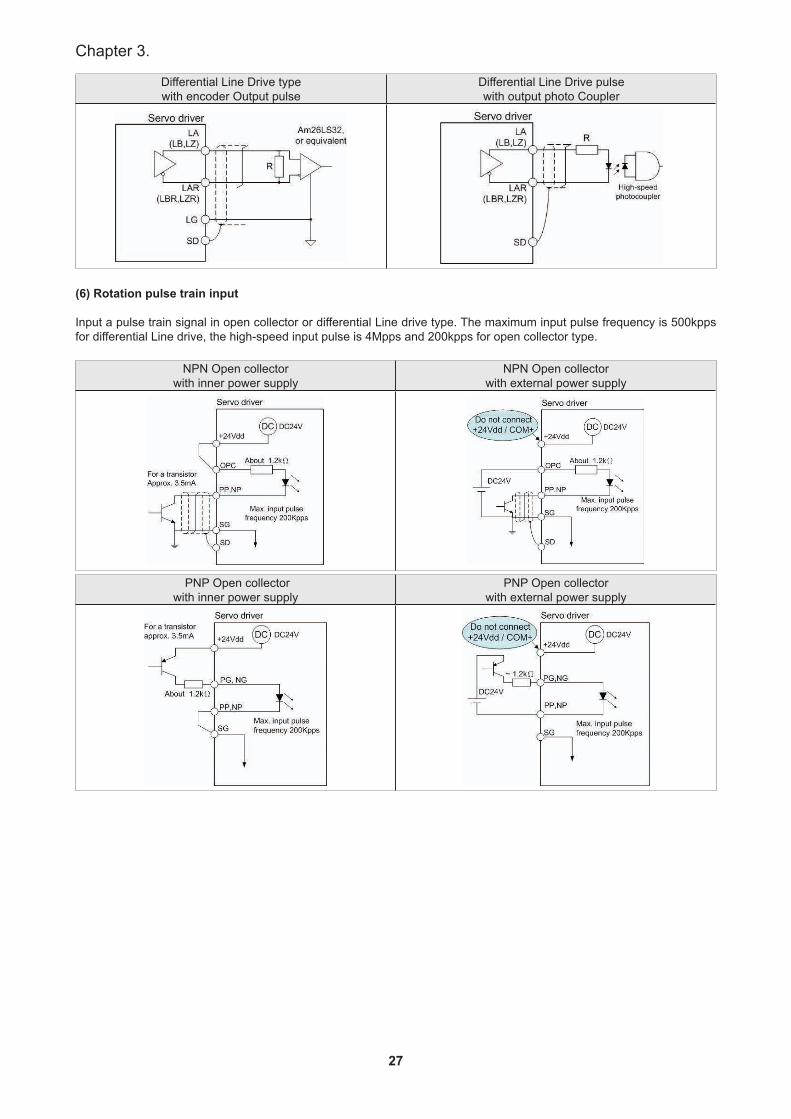
Differential Line Drive type with encoder Output pulse
Differential Line Drive pulse with output photo Coupler
(6) Rotation pulse train input
Input a pulse train signal in open collector or differential Line drive type. The maximum input pulse frequency is 500kpps for differential Line drive, the high-speed input pulse is 4Mpps and 200kpps for open collector type.
NPN Open collector with inner power supply
NPN Open collector with external power supply
PNP Open collectorwith inner power supply
PNP Open collector with external power supply

28
SDH Series Manual
Differential (Line Drive) type
High-speed input pulse, differential (Line Drive) type
NOTE:1. This input system is 5V. Do not be used 24V.Note 2. Suggest the controller connect with the signal ground of servo drive.
29
Chapter 3.
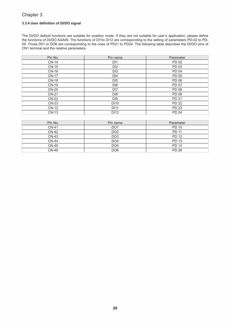
3.3.4 User definition of DI/DO signal
The DI/DO default functions are suitable for position mode. If they are not suitable for user’s application, please define the functions of DI/DO AGAIN. The functions of DI1to DI12 are corresponding to the setting of parameters PD-02 to PD-09. Those D01 to DO6 are corresponding to the ones of PD21 to PD24. The following table describes the DI/DO pins of CN1 terminal and the relative parameters.
Pin No. Pin name ParameterCN-14 DI1 PD 02CN-15 DI2 PD 03CN-16 DI3 PD 04CN-17 DI4 PD 05CN-18 DI5 PD 06CN-19 DI6 PD 07CN-20 DI7 PD 08CN-21 DI8 PD 09CN-22 DI9 PD 21CN-23 DI10 PD 22CN-12 DI11 PD 23CN-13 DI12 PD 24
Pin No. Pin name ParameterCN-41 DO1 PD 10CN-42 DO2 PD 11CN-43 DO3 PD 12CN-44 DO4 PD 13CN-45 DO5 PD 14CN-46 DO6 PD 26
30
SDH Series Manual
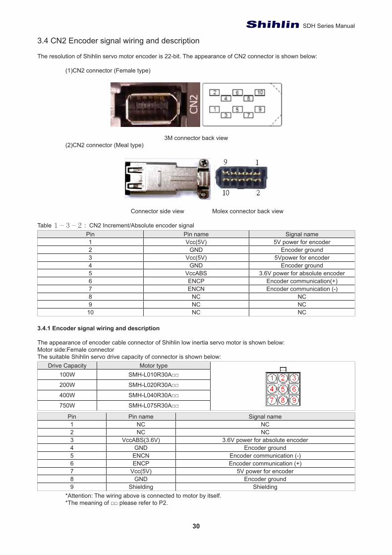
3.4 CN2 Encoder signal wiring and description
The resolution of Shihlin servo motor encoder is 22-bit. The appearance of CN2 connector is shown below:
(1)CN2 connector (Female type)
3M connector back view
(2)CN2 connector (Meal type)
Connector side view Molex connector back view
Table 1-3-2 : CN2 Increment/Absolute encoder signalPin Pin name Signal name1 Vcc(5V) 5V power for encoder2 GND Encoder ground3 Vcc(5V) 5Vpower for encoder4 GND Encoder ground5 VccABS 3.6V power for absolute encoder6 ENCP Encoder communication(+)7 ENCN Encoder communication (-)8 NC NC9 NC NC10 NC NC
3.4.1 Encoder signal wiring and description
The appearance of encoder cable connector of Shihlin low inertia servo motor is shown below:Motor side:Female connectorThe suitable Shihlin servo drive capacity of connector is shown below:
Drive Capacity Motor type100W SMH-L010R30A□□
200W SMH-L020R30A□□
400W SMH-L040R30A□□
750W SMH-L075R30A□□
Pin Pin name Signal name1 NC NC2 NC NC3 VccABS(3.6V) 3.6V power for absolute encoder4 GND Encoder ground5 ENCN Encoder communication (-)6 ENCP Encoder communication (+)7 Vcc(5V) 5V power for encoder8 GND Encoder ground9 Shielding Shielding
*Attention: The wiring above is connected to motor by itself.*The meaning of □□ please refer to P2.
31
Chapter 3.
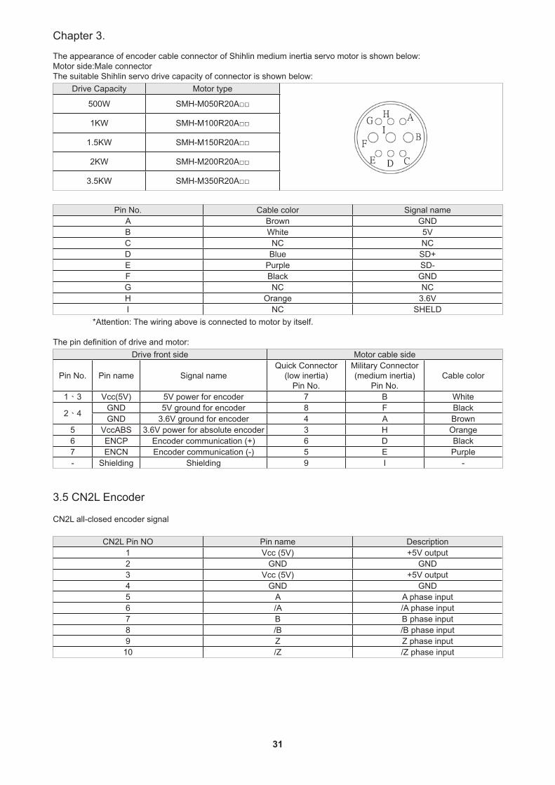
The appearance of encoder cable connector of Shihlin medium inertia servo motor is shown below:Motor side:Male connector The suitable Shihlin servo drive capacity of connector is shown below:
Drive Capacity Motor type
500W SMH-M050R20A□□
1KW SMH-M100R20A□□
1.5KW SMH-M150R20A□□
2KW SMH-M200R20A□□
3.5KW SMH-M350R20A□□
Pin No. Cable color Signal nameA Brown GNDB White 5VC NC NCD Blue SD+E Purple SD-F Black GNDG NC NCH Orange 3.6VI NC SHELD
*Attention: The wiring above is connected to motor by itself.
The pin definition of drive and motor:Drive front side Motor cable side
Pin No. Pin name Signal nameQuick Connector
(low inertia)Pin No.
Military Connector(medium inertia)
Pin No.Cable color
1、3 Vcc(5V) 5V power for encoder 7 B White
2、4 GND 5V ground for encoder 8 F BlackGND 3.6V ground for encoder 4 A Brown
5 VccABS 3.6V power for absolute encoder 3 H Orange6 ENCP Encoder communication (+) 6 D Black7 ENCN Encoder communication (-) 5 E Purple- Shielding Shielding 9 I -
3.5 CN2L Encoder
CN2L all-closed encoder signal
CN2L Pin NO Pin name Description1 Vcc (5V) +5V output2 GND GND3 Vcc (5V) +5V output4 GND GND5 A A phase input6 /A /A phase input7 B B phase input8 /B /B phase input9 Z Z phase input10 /Z /Z phase input
32
SDH Series Manual
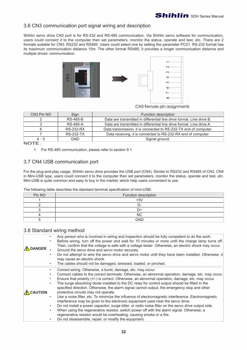
3.6 CN3 communication port signal wiring and description
Shihlin servo drive CN3 port is for RS-232 and RS-485 communication. Via Shihlin servo software for communication, users could connect it to the computer then set parameters, monitor the status, operate and test, etc. There are 2 formats suitable for CN3: RS232 and RS485. Users could select one by setting the parameter PC21. RS-232 format has its maximum communication distance 15m. The other format RS485, it provides a longer communication distance and multiple drives’ communication.
CN3 Pin NO Sign Function description2 RS-485-B Data are transmitted in differential line drive format. Line drive B.3 RS-485-A Data are transmitted in differential line drive format. Line drive A.6 RS-232-RX Data transmission, it is connected to RS-232-TX end of computer.7 RS-232-TX Data receiving, it is connected to RS-232-RX end of computer.
4、5 GND Signal ground.NOTE:
1. For RS-485 communication, please refer to section 9.1
3.7 CN4 USB communication port
For the plug-and-play usage, Shihlin servo drive provides the USB port (CN4). Similar to RS232 and RS485 of CN3, CN4 in Mini-USB type, users could connect it to the computer then set parameters, monitor the status, operate and test, etc. Mini-USB is quite common and easy to buy in the market, which help users convenient to use.
The following table describes the standard terminal specification of mini-USB:Pin NO Function description
1 +5V2 D-3 D+4 NC5 GND
3.8 Standard wiring method• Any person who is involved in wiring and inspection should be fully competent to do the work.• Before wiring, turn off the power and wait for 10 minutes or more until the charge lamp turns off.
Then, confirm that the voltage is safe with a voltage tester .Otherwise, an electric shock may occur.• Ground the servo drive and servo motor securely• Do not attempt to wire the servo drive and servo motor until they have been installed. Otherwise, it
may cause an electric shock.• The cables should not be damaged, stressed, loaded, or pinched.• Correct wiring. Otherwise, a burst, damage, etc. may occur.• Connect cables to the correct terminals. Otherwise, an abnormal operation, damage, etc. may occur.• Ensure that polarity (+/-) is correct. Otherwise, an abnormal operation, damage, etc. may occur.• The surge absorbing diode installed to the DC relay for control output should be fitted in the
specified direction. Otherwise, the alarm signal cannot output, the emergency stop and other protective circuits may not operate.
• Use a noise filter, etc. To minimize the influence of electromagnetic interference. Electromagnetic interference may be given to the electronic equipment used near the servo drive.
• Do not install a power capacitor, surge killer, or radio noise filter on the servo drive output side.• When using the regenerative resistor, switch power off with the alarm signal. Otherwise, a
regenerative resistor would be overheating, causing smoke or a fire.• Do not disassemble, repair, or modify the equipment.
DANGER
CAUTION
33
Chapter 3.
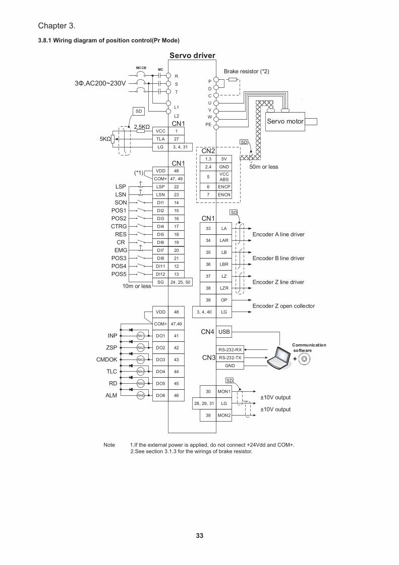
3.8.1 Wiring diagram of position control(Pr Mode)
P
PE
D
WVUC
Brake resistor (*2)
Servo motor
5V
ENCN
ENCP
VCCABS
GND
1,3CN2
SD
SD
Encoder A line driver
Encoder Z line driver
Encoder B line driver
Encoder Z open collector
RS-232-RX
RS-232-TX
GND
CN3
SD
R
L1
L2
T
S
MCMCCB
3Φ,AC200~230V
Servo driver
CN1VCC
TLA
LG
SD
VDD
DO2
DO1
COM+
DO5
DO4
DO3
CN1
USBCN4INP
CMDOK
ZSP
ALM
TLC
CN1
48
42
41
47,49
45
44
43
5KΩ
±10V output
±10V output
2.5KΩ1
27
3, 4, 31
Communication software
+
RES
POS2POS1
SON
CTRG
CREMG
10m or less
(*1) VDD 48
COM+ 47, 49
LSP 22
DI7
DI6
DI5
DI4
DI3
DI2
DI1
LSN
SG
DI8
20
19
18
17
16
15
14
23
24, 25, 50
21
DI11
DI12
12
13
LSPLSN
POS3POS4POS5
DO6 46
RA1
RA2
RA3
RA4
RA5
RA6
RD
2,4
5
6
7
33
36
35
34
38
37
LA
LBR
LB
LAR
LZR
LZ
50m or less
3, 4, 40
39
LG
OP
28, 29, 31
30
LG
MON1
39 MON2
Note 1.If the external power is applied, do not connect +24Vdd and COM+. 2.See section 3.1.3 for the wirings of brake resistor.
34
SDH Series Manual
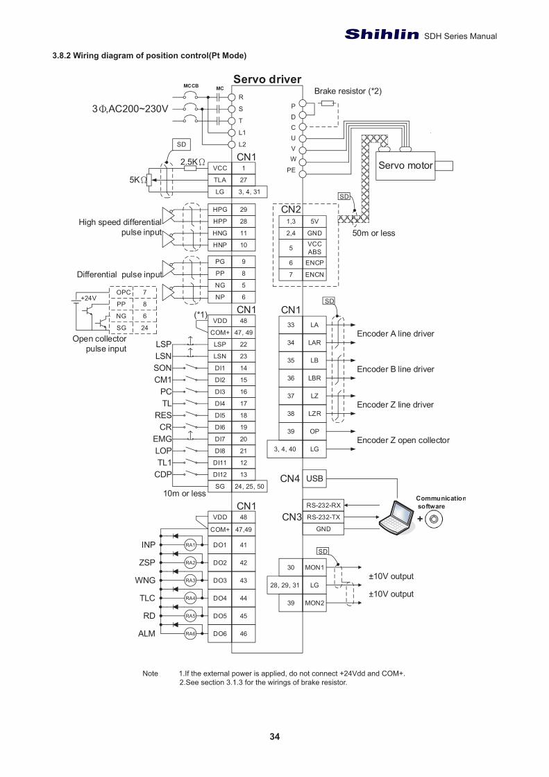
3.8.2 Wiring diagram of position control(Pt Mode)
Note 1.If the external power is applied, do not connect +24Vdd and COM+. 2.See section 3.1.3 for the wirings of brake resistor.
35
Chapter 3.
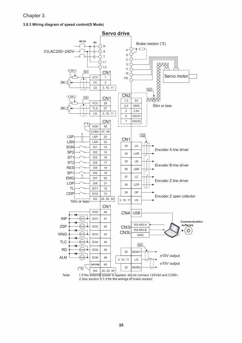
3.8.3 Wiring diagram of speed control(S Mode)
Note 1.If the external power is applied, do not connect +24Vdd and COM+. 2.See section 3.1.3 for the wirings of brake resistor.
36
SDH Series Manual
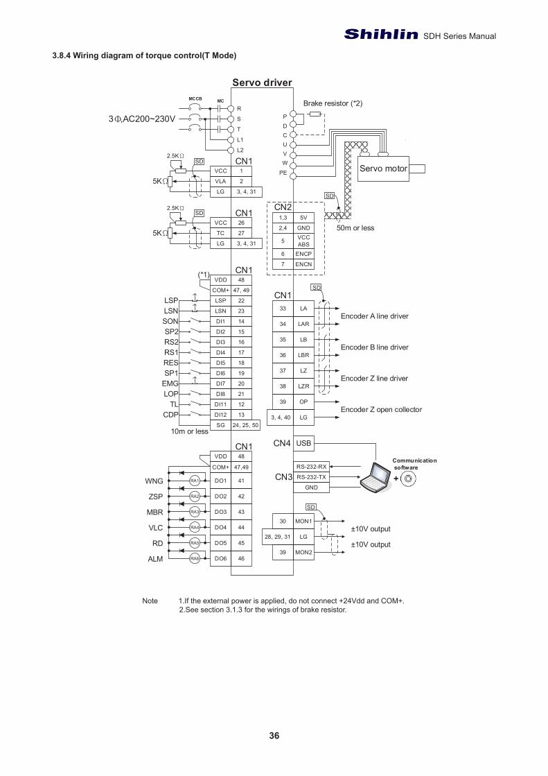
3.8.4 Wiring diagram of torque control(T Mode)
P
PE
D
WVUC
Brake resistor (*2)
Servo motor
5V
ENCN
ENCP
VCCABS
GND
1,3CN2
SD
SD
Encoder A line driver
Encoder Z line driver
Encoder B line driver
Encoder Z open collector
RS-232-RX
RS-232-TX
GNDCN3
SD
R
L1
L2
T
S
MCMCCB
3Φ,AC200~230V
Servo driver
CN1VCC
VLA
LG
SD
SD
VDD
DO2
DO1
COM+
DO5
DO4
DO3
CN1
USBCN4
WNG
MBR
ZSP
ALM
VLC
CN1
48
42
41
47,49
45
44
43
5KΩ
±10V output
±10V output
2.5KΩ
2.5KΩ
1
2
3, 4, 31
Communication software
+
RES
RS2SP2
SON
RS1
SP1EMG
10m or less
(*1)VDD 48
COM+ 47, 49
LSP 22
DI7
DI6
DI5
DI4
DI3
DI2
DI1
LSN
SG
DI8
20
19
18
17
16
15
14
23
24, 25, 50
21
DI11
DI12
12
13
LSPLSN
LOPTL
CDP
DO6 46
RA1
RA2
RA3
RA4
RA5
RA6
RD
2,4
5
6
7
33
36
35
34
38
37
LA
LBR
LB
LAR
LZR
LZ
50m or less
3, 4, 40
39
LG
OP
28, 29, 31
30
LG
MON1
39 MON2
CN1
CN1VCC
TC
LG
5KΩ26
27
3, 4, 31
Note 1.If the external power is applied, do not connect +24Vdd and COM+. 2.See section 3.1.3 for the wirings of brake resistor.
37
Chapter 3.
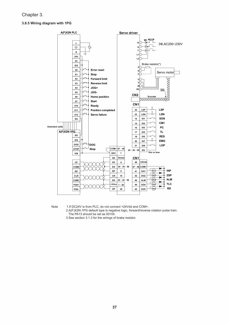
3.8.5 Wiring diagram with 1PG
EncoderCN2
DI7
DI5
DI4
DI3
DI2
DI1
COM+SG
DI8
+24Vdd
DO2
DO1
COM+
DO5
DO4
ALM
RA1
RA1RA3
RA2
RA5
RA4
CN1
CN1
RES
PCCM1SON
TL
EMGLOP
INP
ALMZSP
RDTLC
20
18
17
16
15
14
47、4924、25、50
21
48
42
41
47、49
45
44
46
PP 8
R
L1
L2
TS
MC MCCB
P
PE
D
WVU
C
NP 6
CR 19
+15Vcc 1、26
OP 39
FP
COM0
RP
CLR
COM1
PG0+
PG0-
S/S
DOG
STOP
VIN
SD Shield
OPC 7
X6
X7
X10
X11
X12
X1
X2
X3
X4
X5
L
N
24V
0V
S/S
X0
A(F)X2N-1PG
DOG
SD
LSP
LSN
22
23
24、25、50SG
SG 24、25、50
A(F)X2N PLC
SG
SG
LSPLSN
Servo driver
3Φ,AC200~230V
Servo motor
Brake resistor(*)
10m or less
Extended cable
Stop
Servo failurePosition completedReadyStartHome positionJOG-JOG+Reverse limitForward limitStopError reset
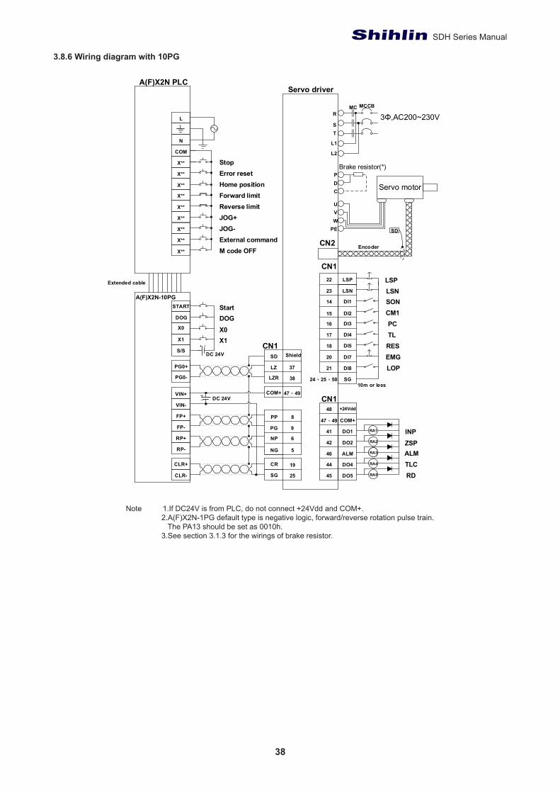
1. If DC24V is from PLC, do not connect +24Vdd and COM+. 2. A(F)X2N-1PG default type is negative logic,forward/reverse rotation pulse train. The PA13 should be set as 0010h. 3. See section 3.1.3 for the wirings of brake resistor.Note 1.If DC24V is from PLC, do not connect +24Vdd and COM+.
2.A(F)X2N-1PG default type is negative logic, forward/reverse rotation pulse train. The PA13 should be set as 0010h. 3.See section 3.1.3 for the wirings of brake resistor.
38
SDH Series Manual
3.8.6 Wiring diagram with 10PG
EncoderCN2
DI7
DI5
DI4
DI3
DI2
DI1
SG
DI8
+24Vdd
DO2
DO1
COM+
DO5
DO4
ALM
RA1
RA1RA3
RA2
RA5
RA4
CN1
CN1
20
18
17
16
15
14
24、25、50
21
48
42
41
47、49
45
44
46
PP 8
R
L1
L2
TS
MC MCCB
P
PE
D
WVU
C
NP 6
NG 5
CR 19
SG 25
SD
LSP
LSN
22
23
PG 9
FP+
FP-
RP+
RP-
CLR+
CLR-
S/S
DOG
X0
X1
X**
X**
X**
X**
X**
X**
X**
L
N
COM
X**
A(F)X2N-10PG
A(F)X2N PLC
X**
START
DC 24V
PG0+
PG0-
VIN+
VIN-
SD Shield
LZR
LZ 37
COM+ 47、49
CN1X1
StartDOGX0
DC 24V
38
Servo driver
3Φ,AC200~230V
Brake resistor(*)
Servo motor
RES
PCCM1SON
TL
EMGLOP
LSPLSN
10m or less
INP
ALMZSP
RDTLC
M code OFFExternal command
Home position
JOG-JOG+Reverse limitForward limit
Error resetStop
Extended cable
1. If DC24V is from PLC, do not connect +24Vdd and COM+. 2. A(F)X2N-10G default type is negative logic,forward/reverse rotation pulse train. The PA13 should be set as 0010h. 3. See section 3.1.3 for the wirings of brake resistor.Note 1.If DC24V is from PLC, do not connect +24Vdd and COM+.
2.A(F)X2N-1PG default type is negative logic, forward/reverse rotation pulse train. The PA13 should be set as 0010h. 3.See section 3.1.3 for the wirings of brake resistor.

39
Chapter 3.
3.8.7 Wiring diagram with 10GM
EncoderCN2
LSP
DI7
DI5
DI4
DI3
DI2
DI1
LSN
SG
DI8
+24Vdd
DO2
COM+
DO4
ALM RA1RA3
RA2
RA4
CN1
ARMZSP
TLC
22
20
18
17
16
15
14
23
24、25、50
21
48
42
47、49
44
46
PP 8
R
L1
L2
TS
MC MCCB
P
PE
D
WVU
C
NP 6
SG
CR 19
OP 39
+15Vcc 1、26
SG
6
9
16
3
4
13
14
INP 41
16
17
18
10
20
12
13
14
9
15
9
2
3
4
19
11
A(F)X2N-10GM
SD
DC 24V
Start
1
2
11
SD Shield
(DO5)
(DO1)
6
7
8
5
1
OPC 7
DC 5~24V
StopHome position
Manual FWDManual REVDOGFWD limitREV limit
General input
CON1
CON1
CON2 VDD 48
9
FP
COM5
RP
CLR
COM3
PGO
COM4
Y1
Y2
Y3
Y4
Y5
X1
X2
X3
COM1
Y0
COM1
STOP
ZRN
FWD
COM1
X0
SVRDY
COM2
SVEND
VIN
DOG
LSF
LSR
RVS
START
COM5
7,8,17,18
CN1
45RD
47、49COM+
24、25、50
24、25、50
41
45 DO5
DO1 RA1
RA5
INP
RD
VDD48
47、49 COM+CN1
Servo driver
3Φ,AC200~230V
Brake resistor(*)
Servo motor
1. If DC24V is from , do not connect +24Vdd and COM+. 2. A(F)X2N-10GM default type is negative logic, forward/reverse rotation pulse train. The PA13 should be as 0010h. 3. See section 3.1.3 for the wirings of brake resistor..
RES
PCCM1SON
TL
EMGLOP
LSPLSN
10m or less
General putput
Note 1.If DC24V is from PLC, do not connect +24Vdd and COM+. 2.A(F)X2N-1PG default type is negative logic, forward/reverse rotation pulse train. The PA13 should be set as 0010h. 3.See section 3.1.3 for the wirings of brake resistor.
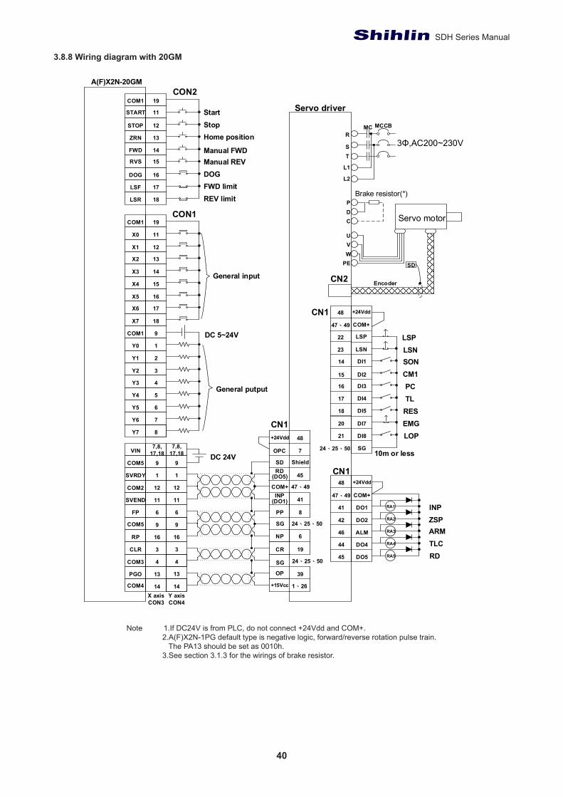
40
SDH Series Manual
3.8.8 Wiring diagram with 20GM
EncoderCN2
DI7
DI5
DI4
DI3
DI2
DI1
SG
DI8
CN1
20
18
17
16
15
14
24、25、50
21
R
L1
L2
TS
MC MCCB
P
PE
D
WVU
C
2
3
4
5
6
9
1
A(F)X2N-20GM
SD
DC 5~24V
PP 8
NP 6
SG
CR 19
OP 39
+15Vcc
SG
6
16
3
13
41
DC 24V
1
12
11
SD Shield
COM+
9
+24Vdd 48
OPC 7
7
8
19
12
13
14
16
17
18
15
11
12
13
14
19
11
16
17
18
15
CON2
CON1
INP
RD(DO5)
(DO1)
Y1
Y2
Y3
Y4
Y5
COM1
Y0
Y6
Y7
COM1
STOP
ZRN
FWD
DOG
LSF
LSR
RVS
START
X1
X2
X3
COM1
X0
X5
X6
X7
X4
7,8,17,18
9
4
14
CN1
45
47、49
24、25、50
24、25、50
FP
RP
CLR
PGO
SVRDY
SVEND
VIN
COM5
COM2
COM5
COM3
COM4
6
16
3
13
1
12
11
9
7,8,17,18
9
4
14X axisCON3
Y axis CON4
+24Vdd
DO2
DO1
COM+
DO5
DO4
ALM
RA1
RA1RA3
RA2
RA5
RA4
CN148
42
41
47、49
45
44
46
1、26
+24Vdd
COM+
48
47、49
LSP
LSN
22
23
Servo driver
3Φ,AC200~230V
Brake resistor(*)
Servo motor
RES
PCCM1SON
TL
EMGLOP
LSPLSN
10m or less
ARMZSP
TLC
INP
RD
1. If DC24V is from PLC, do not connect +24Vdd and COM+. 2. A(F)X2N-20GM default type is negative logic, forward/reverse rotation pulse train. The PA13 should be as 0010h. 3. See section 3.1.3 for the wirings of brake resistor.
General putput
General input
StartStopHome position
Manual FWDManual REVDOGFWD limitREV limit
Note 1.If DC24V is from PLC, do not connect +24Vdd and COM+. 2.A(F)X2N-1PG default type is negative logic, forward/reverse rotation pulse train. The PA13 should be set as 0010h. 3.See section 3.1.3 for the wirings of brake resistor.
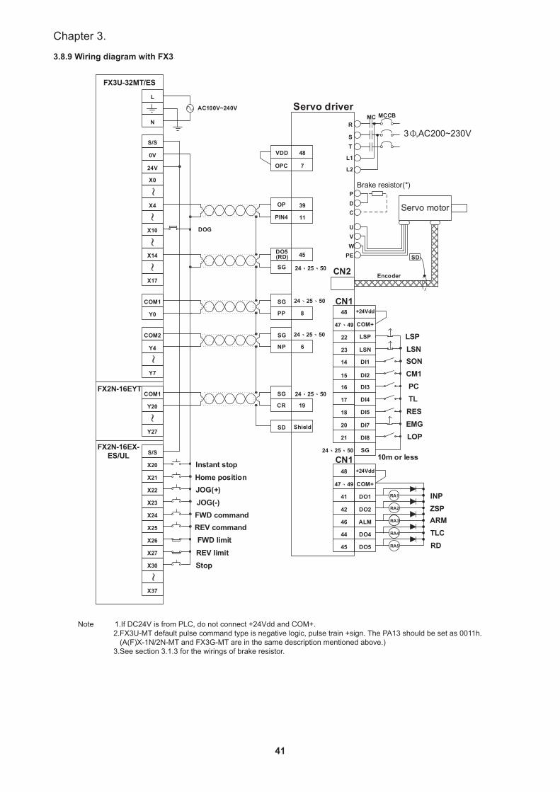
41
Chapter 3.
3.8.9 Wiring diagram with FX3
EncoderCN2
DI7
DI5
DI4
DI3
DI2
DI1
SG
DI8
CN1
20
18
17
16
15
14
24、25、50
21
R
L1
L2
TS
MC MCCB
P
PE
D
WVU
CServo motor
COM2
Y4
Y7
COM1
COM1
Y0
FX3U-32MT/ES
SD
X23
X24
X25
X26
X27
X30
X20
X21
X22
S/S
Y20
Instant stop
AC100V~240V
24V
X0
~S/S
0V
X10
X4
X14
X17
~~
~~
Y27
~~
X37
OP 39
PIN4 11
DO5 45(RD)
SG
SG
SG
CR 19
SG
VDD 48
OPC 7
PP 8
NP 6
L
N
Home positionJOG(+)JOG(-)FWD commandREV commandFWD limitREV limitStop
FX2N-16EYT
FX2N-16EX-ES/UL
SD Shield
24、25、50
24、25、50
24、25、50
24、25、50
DOG
+24Vdd
DO2
DO1
COM+
DO5
DO4
ALM
RA1
RA1RA3
RA2
RA5
RA4
CN148
42
41
47、49
45
44
46
+24Vdd
COM+
48
47、49
LSP
LSN
22
23
Servo driver
3Φ,AC200~230V
Brake resistor(*)
RES
PCCM1SON
TL
EMGLOP
LSPLSN
10m or less
ARMZSP
TLC
INP
RD
※1. If DC24V is from PLC, do not connect +24Vdd and COM+.※2. FX3U-MT default pulse command type is negative logic, pulse train + sign. The PA13 should be set as 0011h. (A(F)X-1N/2N-MT and FX3G-MT are in the same description mentioned above.)※3. See section 3.1.3 for the wirings of brake resistor.
Note 1.If DC24V is from PLC, do not connect +24Vdd and COM+. 2.FX3U-MT default pulse command type is negative logic, pulse train +sign. The PA13 should be set as 0011h. (A(F)X-1N/2N-MT and FX3G-MT are in the same description mentioned above.) 3.See section 3.1.3 for the wirings of brake resistor.
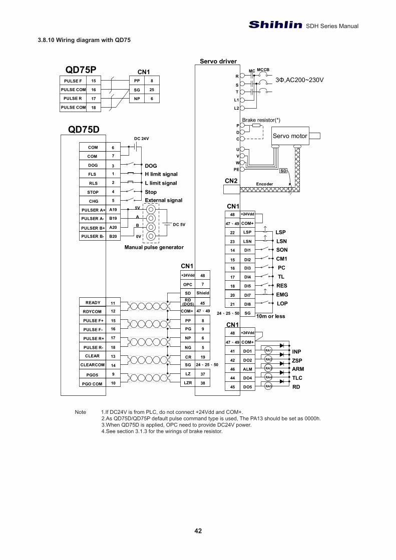
42
SDH Series Manual
3.8.10 Wiring diagram with QD75
EncoderCN2
DI7
DI5
DI4
DI3
DI2
DI1
SG
DI8
CN1
20
18
17
16
15
14
24、25、50
21
R
L1
L2
TS
MC MCCB
P
PE
D
WVU
C
SD
PP 8
NP 6
PG 9
NG 5
SG
LZ 37
CR 19
SD ShieldRD
45(DO5)
QD75D
LZR 38
+24Vdd
OPC
48
7
15
14
9
11
10
PULSE F+
PULSE F-
PULSE R+
PULSE R-
CLEARCOM
PGO5
PGO COM
READY
RDYCOM
CLEAR
12
16
17
18
13
3
RLS
STOP
CHG
DOG
FLS 1
4
5
6COM
COM 7
2
DC 24V
18
17
16
6
25
NP
SG
8PP15PULSE F
PULSE COM
PULSE COM
PULSE R
QD75P
CN1
CN1
47、49
24、25、50
PULSER A-
PULSER B+
PULSER B-
PULSER A+ A19
A20
B20
B19
5V
A
B
0V
DC 5V
+24Vdd
DO2
DO1
COM+
DO5
DO4
ALM
RA1
RA1RA3
RA2
RA5
RA4
CN148
42
41
47、49
45
44
46
COM+
+24Vdd
COM+
48
47、49
LSP
LSN
22
23
Servo driver
3Φ,AC200~230V
Brake resistor(*)
Servo motor
10m or less
RES
PCCM1SON
TL
EMGLOP
LSPLSN
ARMZSP
TLC
INP
RD
External signalStopL limit signalH limit signalDOG
Manual pulse generator
1. If DC24V is from PLC, do not connect +24Vdd and COM+. 2. AS QD75D/QD75P default pulse command type is used, the PA13 should be set as 0000h. 3. When QD75D is applied , OPC is without providing power. 4. See section 3.1.3 for the wirings of brake resistor. 5. This signal frequency for this diagram is 500Kpps. If the signal frequency excesses 500Kpps, please refer to section 3.8.2. Refer to the wirings of high-speed input pulse.
Note 1.If DC24V is from PLC, do not connect +24Vdd and COM+. 2.As QD75D/QD75P default pulse command type is used, The PA13 should be set as 0000h. 3.When QD75D is applied, OPC need to provide DC24V power. 4.See section 3.1.3 for the wirings of brake resistor.

43
Chapter 3.
3.8.11 Wiring diagram with Gantry
P PED WVUC
Bra
ke re
sist
or(*
)
Serv
o m
otor
Enc
oder
SD
RL1L2 T S
MC
MC
CB
3ΦA
C20
0V~2
30V
Serv
o dr
iver
1
50m
or l
ess
Diff
eren
tial t
ype
CN
12.
5KΩ
5KΩ
CN
1H
igh-
spee
d in
put p
ulse
Diff
eren
tial t
ype
SD
/A
CN
2L
P PED WVUC
Bra
ke re
sist
or(*
)
Serv
o m
otor En
code
rSD
RL1L2 T S
MC
MC
CB
3ΦA
C20
0V~2
30V
Serv
o dr
iver
2
50m
or l
ess
Diff
eren
tial t
ype
CN
12.
5KΩ
5KΩ
CN
1H
igh-
spee
d in
put p
ulse
Diff
eren
tial t
ype
SD
A B/A
5 109876CN
2L
/B Z /Z
Opt
ical
sca
le in
put
Opt
ical
sca
le in
put
A Pulse+
Con
trol
ler
A Pulse-
B Pulse+
B Pulse-
CN
2
5V1、
3
765
2、4
GN
D
ENC
P
ENC
N
LA LZR
LZLBR
LBLAR
33 3837363534
HP
P
HN
G
HN
P
HP
G
28 111029
VCC
TLA
LG
1 27 3、4、
31
CN
2
5V1、
3
765
2、4
GN
D
ENC
P
ENC
N
3、4、
31
VCC
TLA
LG
1 27
HP
P
HN
G
HN
P
HP
G
28 111029
PG NP
NGPP
9 6 58
LA LZR
LZLBR
LBLAR
33 3837363534
A B
5 109876
/B Z /Z
I/O
VDD
DO
2
DO
1
CO
M+
DO
5
DO
4
DO
3
RA
1
RA
1R
A3
RA
2
RA
5
RA
4
CN
1
48 4241
47、
49
454443
RA
6D
O6
46
INP
WN
G
ZSP
RD
TLC
ALM
LSP
DI7
DI6
DI5
DI4
DI3
DI2
DI1
LSN
DI8
CN
1
10m
or l
ess
22 2019181716151423 21
VDD
CO
M+
48
47、
49
SG24
、25
、50
DI1
112
DI1
213
TL1
CD
P
RE
S
PCCM
1
SON
TL CR EM
G
LOP
LSP
LSN
VDD
DO
2
DO
1
CO
M+
DO
5
DO
4
DO
3
RA
1
RA
1R
A3
RA
2
RA
5
RA
4
CN
1
48 4241
47、
49
454443
RA
6D
O6
46
INP
WN
G
ZSP
RD
TLC
ALM
LSP
DI7
DI6
DI5
DI4
DI3
DI2
DI1
LSN
DI8
CN
1
10m
or l
ess
22 2019181716151423 21
VDD
CO
M+
48
47、
49
SG24
、25
、50
DI1
112
DI1
213
TL1
CD
P
RE
S
PCCM
1
SON
TL CR
EMG
LOP
LS
P
LS
N
PG9
PP8
NG
5
NP
6
VCC
AB
SVC
CA
BS
( *)

44
SDH Series Manual
4. Panel display and operation
This chapter describes the conditions of Shihlin servo drive’s panel and all operation.
4.1 Panel components
Name Function description
LED display This display with 7-segment LED of 5 digits, is used to monitor the states of servo and the value of parameters, and set modification value.
MODE keyTo switch one display mode to the others. Shihlin servo drive has parameter display mode, alarm history mode, status monitor mode, etc.This button becomes to “Shift “function when in parameter writing-in mode.
UP key To increase the value which denoted parameter or set value.DOWN key To decrease the value which denoted parameter or set value.
SET key To show or save the value which is operated.Power indicator To indicate the power status.
4.2 Display flowchart
Use the display on the front side of servo drive for status display, parameter setting, etc. Set the parameter before operation, diagnose an alarm, confirm external sequences, and confirm the operation status. Press the “MODE" “UP”and “DOWN”" buttons once to the next screen.To refer to or set the expansion parameter, make them valid with PA42.
Chart 1:Display flowchart

45
Chapter 4.
4.3 Status display
The operation status of Shihlin servo could be displayed on the 5-digit 7 segment LED display.Press the “UP” or “DOWN” key to change the display data as desired.When the required data is selected, the corresponding symbol appears. Press the “SET” key to display the information.7 segment LED display could show the 5 digits of 16 items such as motor speed.A negative value which occupies 5 digits is displayed by the 5 lit decimal points. If a negative value which occupies only 4 digits or less, the negative symbol “-“ is displayed at the highest digit.
ExamplesThe following table lists the display examples:
Item Status Display device7 segment LED display.
Motor rotation speed
Forward rotation at 500r/min
Reverse rotation at 3000r/min
The ratio of load inertia to motor shaft 15.5times
Motor feedback revolution (high digit)
Value is 1234567890Display high digit -> 1234.5
Motor feedback revolution (low digit)
Value is1234567890Display low digit -> 67890.
Parameter setting accomplished a successful write-in
Parameter setting failed Servo on (SON on) a failed write-in
Please do SON off and write-in again.
Parameter setting over range Parameter setting over range
Write-in parameter setting value again
PS: The details of display panel, please refer to the parameter value of section 1.6 for examplesNOTE: When setting the panel parameters, each parameter has the high/low limit values range. When the decimal data changes, value has high/low limit.When the hexadecimal data changes, Hex value has high/low limit.
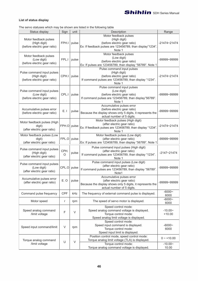
46
SDH Series Manual
List of status display
The servo statuses which may be shown are listed in the following tableStatus display Sign unit Description Range
Motor feedback pulses (High digit)
(before electric gear ratio)FPH.I pulse
Motor feedback pulses (High digit)
(before electric gear ratio)Ex: If feedback pulses are 123456789, than display”1234”.
Note 1
-21474~21474
Motor feedback pulses (Low digit)
(before electric gear ratio)FPL.I pulse
Motor feedback pulses (Low digit)
(before electric gear ratio)Ex: If pulses are 123456789, than display “56789”. Note 1
-99999~99999
Pulse command input pulses(High digit)
(before electric gear ratio)CPH.I pulse
Pulse command input pulses(High digit)
(before electric gear ratio)If command pulses are 123456789, than display “1234”.
Note 1
-21474~21474
Pulse command input pulses (Low digit)
(before electric gear ratio)CPL.I pulse
Pulse command input pulses (Low digit)
(before electric gear ratio)If command pulses are 123456789, than display”56789”.
Note 1
-99999~99999
Accumulative pulses error (before electric gear ratio) E. I pulse
Accumulative pulses error (before electric gear ratio)
Because the display shows only 5 digits, it represents the actual number of 5 digits.
-99999~99999
Motor feedback pulses (High digit)
(after electric gear ratio)FPH.O pulse
Motor feedback pulses (High digit)(after electric gear ratio)
Ex: If feedback pulses are 123456789, than display “1234”. Note 1
-21474~21474
Motor feedback pulses (Low digit)
(after electric gear ratio)FPL.O pulse
Motor feedback pulses (Low digit)(after electric gear ratio)
Ex: If pulses are 123456789, than display “56789”. Note 1-99999~99999
Pulse command input pulses (High digit)
(after electric gear ratio)
CPH.O pulse
Pulse command input pulses (High digit)(after electric gear ratio)
If command pulses are 123456789, than display “1234”. Note 1
-2147~21474
Pulse command input pulses (Low digit)
(after electric gear ratio)CPL.O pulse
Pulse command input pulses (Low digit)(after electric gear ratio)
If command pulses are 123456789, than display “56789”. Note1
-99999~99999
Accumulative pulses error (after electric gear ratio) E. O pulse
Accumulative pulses error (after electric gear ratio)
Because the display shows only 5 digits, it represents the actual number of 5 digits.
-99999~99999
Command pulse frequency CPF kHz The frequency of external command pulse is displayed. -6000~6000
Motor speed r rpm The speed of servo motor is displayed. -6000~6000
Speed analog command/limit voltage F V
Speed control mode:Speed analog command voltage is displayed.
Torque control mode:Speed analog limit voltage is displayed.
-10.00~+10.00
Speed input command/limit V rpm
Speed control mode:Speed input command is displayed.
Torque control mode:Speed input limit is displayed.
-6000~6000
Torque analog command/limit voltage U V
Position control mode, speed control mode:Torque analog limit voltage (TLA) is displayed. 0 ~ +10.00
Torque control mode:Torque analog command voltage is displayed.
-10.00~10.00
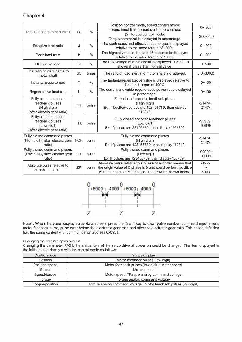
47
Chapter 4.
Torque input command/limit TC %
Position control mode, speed control mode:Torque input limit is displayed in percentage. 0~ 300
(2) Torque control mode:Torque command is displayed in percentage. -300~300
Effective load ratio J % The continuous and effective load torque is displayed relative to the rated torque of 100%. 0~ 300
Peak load ratio b % The highest value in the past 15 seconds is displayed relative to the rated torque of 100%. 0~ 300
DC bus voltage Pn V The P-N voltage of main circuit is displayed. “Lo-dC” is shown if it less than normal value. 0~500
The ratio of load inertia to motor shaft dC times The ratio of load inertia to motor shaft is displayed. 0.0~300.0
Instantaneous torque T % The Instantaneous torque value is displayed relative to the rated torque of 100%. 0~100
Regenerative load rate L % The current allowable regenerative power ratio displayed in percentage. 0~100
Fully closed encoder feedback pluses
(High digit)(after electric gear ratio)
FFH pulse
Fully closed encoder feedback pluses(High digit)
Ex: If feedback pulses are 123456789, than display “1234”.
-21474~21474
Fully closed encoder feedback pluses
(Low digit)(after electric gear ratio)
FFL pulseFully closed encoder feedback pluses
(Low digit)Ex: If pulses are 23456789, than display “56789”.
-99999~99999
Fully closed command pluses(High digit)( after electric gear
ratio)FCH pulse
Fully closed command pluses(High digit)
Ex: If pulses are 123456789, than display “1234”.
-21474~21474
Fully closed command pluses (Low digit)( after electric gear
ratio)FCL pulse
Fully closed command pluses (Low digit)
Ex: If pulses are 123456789, than display “56789”.
-99999~99999
Absolute pulse relative to encoder z-phase ZP pulse
Absolute pulse relative to z-phase of encoder means that the origin value of Z phase is 0 and could be form positive 5000 to negative 5000 pulse, The drawing shown below.
-4999~
5000
Note1: When the panel display value data screen, press the “SET” key to clear pulse number, command input errors, motor feedback pulse, pulse error before the electronic gear ratio and after the electronic gear ratio. This action definition has the same content with communication address 0x0951.
Changing the status display screenChanging the parameter PA01, the status item of the servo drive at power on could be changed. The item displayed in the initial status changes with the control mode as follows:
Control mode Status displayPosition Motor feedback pulses (low digit)
Position/speed Motor feedback pulses (low digit) / Motor speedSpeed Motor speed
Speed/torque Motor speed / Torque analog command voltageTorque Torque analog command voltage
Torque/position Torque analog command voltage / Motor feedback pulses (low digit)
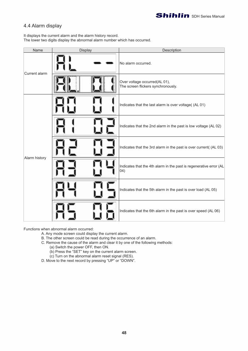
48
SDH Series Manual
4.4 Alarm display
It displays the current alarm and the alarm history record.The lower two digits display the abnormal alarm number which has occurred.
Name Display Description
Current alarm
No alarm occurred.
Over voltage occurred(AL 01),The screen flickers synchronously.
Alarm history
Indicates that the last alarm is over voltage( (AL 01)
Indicates that the 2nd alarm in the past is low voltage (AL 02)
Indicates that the 3rd alarm in the past is over current( (AL 03)
Indicates that the 4th alarm in the past is regenerative error (AL 04)
Indicates that the 5th alarm in the past is over load (AL 05)
Indicates that the 6th alarm in the past is over speed (AL 06)
Functions when abnormal alarm occurred:A. Any mode screen could display the current alarm.B. The other screen could be read during the occurrence of an alarm. C. Remove the cause of the alarm and clear it by one of the following methods:
(a) Switch the power OFF, then ON. (b) Press the “SET” key on the current alarm screen. (c) Turn on the abnormal alarm reset signal (RES).
D. Move to the next record by pressing “UP” or “DOWN”.
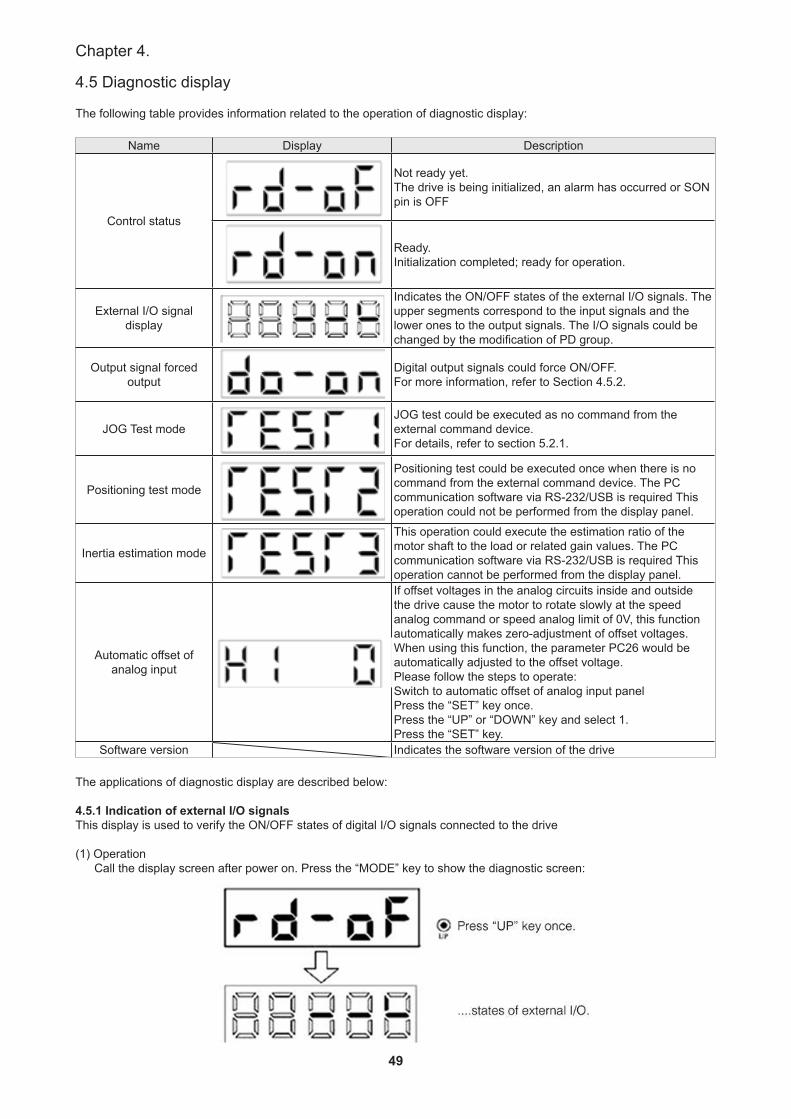
49
Chapter 4.
4.5 Diagnostic display
The following table provides information related to the operation of diagnostic display:
Name Display Description
Control status
Not ready yet.The drive is being initialized, an alarm has occurred or SON pin is OFF
Ready.Initialization completed; ready for operation.
External I/O signaldisplay
Indicates the ON/OFF states of the external I/O signals. The upper segments correspond to the input signals and the lower ones to the output signals. The I/O signals could be changed by the modification of PD group.
Output signal forcedoutput
Digital output signals could force ON/OFF.For more information, refer to Section 4.5.2.
JOG Test modeJOG test could be executed as no command from the external command device.For details, refer to section 5.2.1.
Positioning test mode
Positioning test could be executed once when there is no command from the external command device. The PC communication software via RS-232/USB is required This operation could not be performed from the display panel.
Inertia estimation mode
This operation could execute the estimation ratio of the motor shaft to the load or related gain values. The PC communication software via RS-232/USB is required This operation cannot be performed from the display panel.
Automatic offset of analog input
If offset voltages in the analog circuits inside and outside the drive cause the motor to rotate slowly at the speed analog command or speed analog limit of 0V, this function automatically makes zero-adjustment of offset voltages.When using this function, the parameter PC26 would be automatically adjusted to the offset voltage.Please follow the steps to operate:Switch to automatic offset of analog input panelPress the “SET” key once.Press the “UP” or “DOWN” key and select 1.Press the “SET” key.
Software version Indicates the software version of the drive
The applications of diagnostic display are described below:
4.5.1 Indication of external I/O signalsThis display is used to verify the ON/OFF states of digital I/O signals connected to the drive
(1) OperationCall the display screen after power on. Press the “MODE” key to show the diagnostic screen:
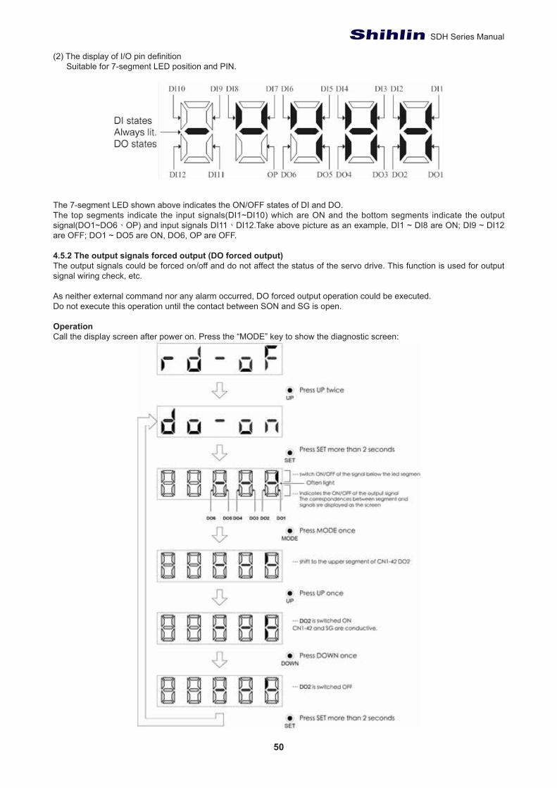
50
SDH Series Manual
(2) The display of I/O pin definitionSuitable for 7-segment LED position and PIN.
The 7-segment LED shown above indicates the ON/OFF states of DI and DO.The top segments indicate the input signals(DI1~DI10) which are ON and the bottom segments indicate the output signal(DO1~DO6、OP) and input signals DI11、DI12.Take above picture as an example, DI1 ~ DI8 are ON; DI9 ~ DI12 are OFF; DO1 ~ DO5 are ON, DO6, OP are OFF.
4.5.2 The output signals forced output (DO forced output)The output signals could be forced on/off and do not affect the status of the servo drive. This function is used for output signal wiring check, etc.
As neither external command nor any alarm occurred, DO forced output operation could be executed.Do not execute this operation until the contact between SON and SG is open.
OperationCall the display screen after power on. Press the “MODE” key to show the diagnostic screen:
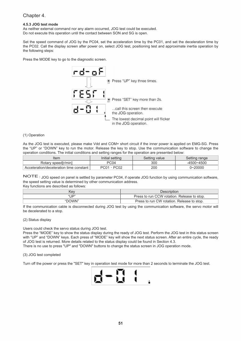
51
Chapter 4.
4.5.3 JOG test modeAs neither external command nor any alarm occurred, JOG test could be executed.Do not execute this operation until the contact between SON and SG is open.
Set the speed command of JOG by the PC04, set the acceleration time by the PC01, and set the deceleration time by the PC02. Call the display screen after power on, select JOG test, positioning test and approximate inertia operation by the following steps:
Press the MODE key to go to the diagnostic screen.
(1) Operation
As the JOG test is executed, please make Vdd and COM+ short circuit if the inner power is applied on EMG-SG. Press the “UP” or “DOWN” key to run the motor. Release the key to stop. Use the communication software to change the operation conditions. The initial conditions and setting ranges for the operation are presented below:
Item Initial setting Setting value Setting rangeRotary speed[r/min] PC04 300 -4500~4500
Acceleration/deceleration time constant PC01、PC02 200 0~20000
NOTE:JOG speed on panel is settled by parameter PC04, if operate JOG function by using communication software, the speed setting value is determined by other communication address.Key functions are described as follows:
Key Description“UP” Press to run CCW rotation. Release to stop.
“DOWN” Press to run CW rotation. Release to stop. If the communication cable is disconnected during JOG test by using the communication software, the servo motor will be decelerated to a stop.
(2) Status display
Users could check the servo status during JOG test.Press the “MODE” key to show the status display during the ready of JOG test. Perform the JOG test in this status screen with “UP” and “DOWN” keys. Each press of “MODE” key will show the next status screen. After an entire cycle, the ready of JOG test is returned. More details related to the status display could be found in Section 4.3.There is no use to press "UP" and "DOWN" buttons to change the status screen in JOG operation mode.
(3) JOG test completed
Turn off the power or press the "SET" key in operation test mode for more than 2 seconds to terminate the JOG test.
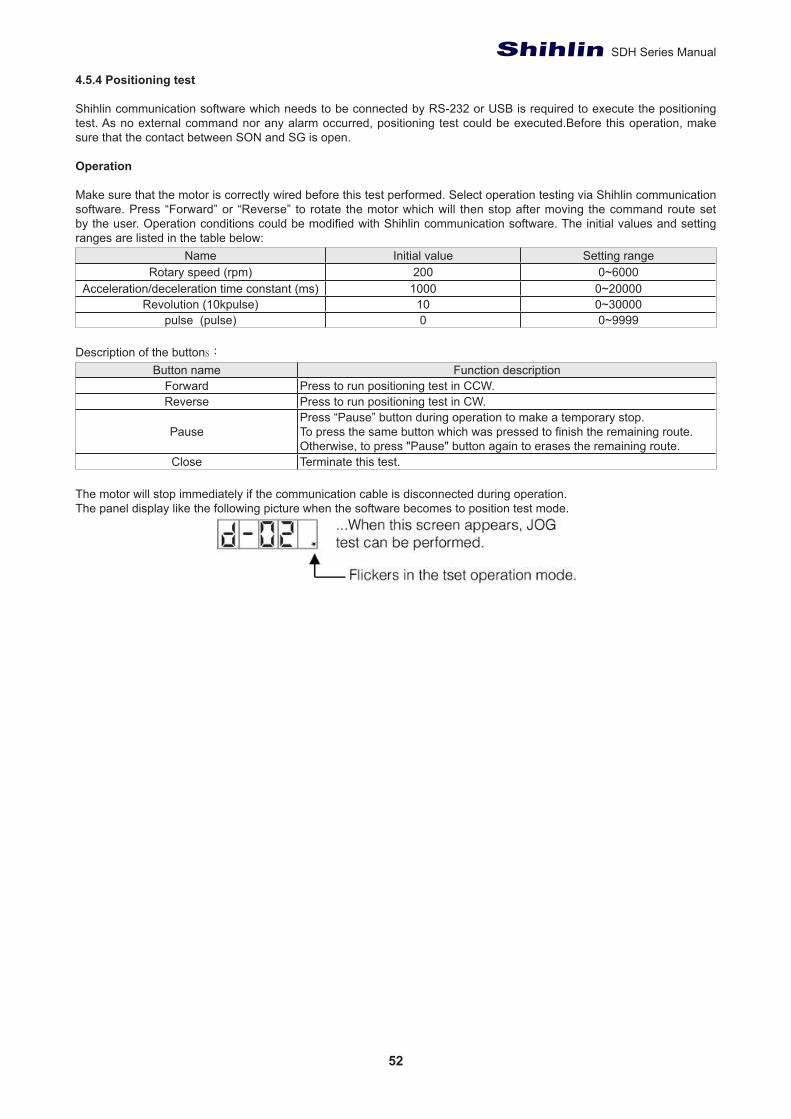
52
SDH Series Manual
4.5.4 Positioning test
Shihlin communication software which needs to be connected by RS-232 or USB is required to execute the positioning test. As no external command nor any alarm occurred, positioning test could be executed.Before this operation, make sure that the contact between SON and SG is open.
Operation
Make sure that the motor is correctly wired before this test performed. Select operation testing via Shihlin communication software. Press “Forward” or “Reverse” to rotate the motor which will then stop after moving the command route set by the user. Operation conditions could be modified with Shihlin communication software. The initial values and setting ranges are listed in the table below:
Name Initial value Setting range Rotary speed (rpm) 200 0~6000
Acceleration/deceleration time constant (ms) 1000 0~20000Revolution (10kpulse) 10 0~30000
pulse (pulse) 0 0~9999
Description of the buttons: Button name Function description
Forward Press to run positioning test in CCW. Reverse Press to run positioning test in CW.
PausePress “Pause” button during operation to make a temporary stop. To press the same button which was pressed to finish the remaining route. Otherwise, to press "Pause" button again to erases the remaining route.
Close Terminate this test.
The motor will stop immediately if the communication cable is disconnected during operation.The panel display like the following picture when the software becomes to position test mode.
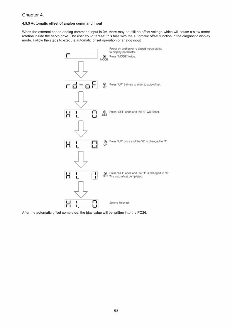
53
Chapter 4.
4.5.5 Automatic offset of analog command input
When the external speed analog command input is 0V, there may be still an offset voltage which will cause a slow motor rotation inside the servo drive. The user could “erase” this bias with the automatic offset function in the diagnostic display mode. Follow the steps to execute automatic offset operation of analog input:
After the automatic offset completed, the bias value will be written into the PC26.

54
SDH Series Manual
4.5.6 Inertia estimation
Shihlin communication software which needs to be connected by RS-232 or USB is required to execute the positioning test. As no external command nor any alarm occurred, positioning test could be executed.
Operation
Make sure that the motor is wired correctly before operating this inertia estimation. Under Shihlin communication window, choose the “auto gain tuning” item.Inertia estimation operation method:
• Select the “Auto tuning control panel”.• The acceleration/deceleration time constant, S type acceleration/deceleration time constant and JOG speed
could be set in no alarm situation by pressing the “Set “button.• Press the “Servo ON” button and then the motor would be magnetized• Press the “JOG” left or right button to control the motor in CCW or CW and to the position, set position 1, then
press the” JOG” button, set the position 2.• When position 1 and 2 setting finished press “start “button to run estimate inertia and gain operation.• When the response is not enough, you can set response at operation menu directly, but don’t set the response
value too high instantly, please increase step by step.• After the values getting more stable or customers were satisfied with the machine characteristics, press the
“Stop” button to finish estimate inertia and gain operation.• Cancel the auto gain control panel options.
During the acceleration or deceleration process, the servo drive would calculate the ratio of load inertia to motor shaft and the bandwidth of the system. The relevant parameters are listed below:
Name Abbr. Sign Setting range Unit Initial value Control modeResonance suppression low-pass filter NLP PB03 0~10000 0.1ms 10 Pt、Pr、S、T
Position feed-forward gain FFC PB 05 0~200 % 0 Pt、PrThe ratio of load inertia to motor shaft GD1 PB 06 0~1200 0.1time 70 Pt、Pr、S
Position loop gain PG1 PB07 4~1024 rad/s 45 Pt、PrSpeed loop gain VG1 PB08 40~9000 rad/s 183 Pt、Pr、S
Speed integral gain VIC PB 09 1~1000 ms 34 Pt、Pr、S
The panel display like the following picture when the software becomes to inertia estimation mode.
4.6 Parameter display
4.6.1 16bit parameter setting methodSome parameter modification would be valid by power off once and power on again.
Operation method
Here is an example. This is the operation method of changing the control mode (PA01) to speed control mode after power off and power on again. Example:Change the control mode (PA01) to the speed control mode.Use the “MODE” key to switch to the “PA 01”parameter menu.
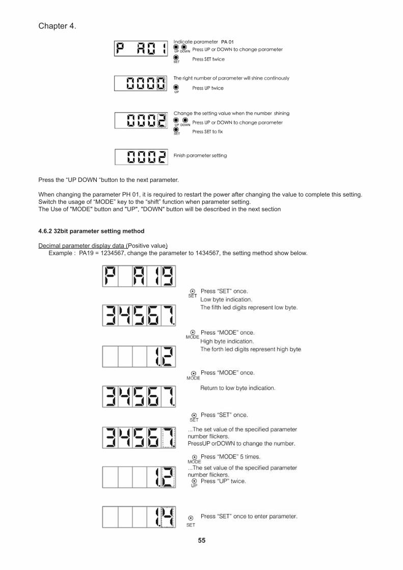
55
Chapter 4.
Press the “UP DOWN “button to the next parameter.
When changing the parameter PH 01, it is required to restart the power after changing the value to complete this setting.Switch the usage of “MODE” key to the “shift” function when parameter setting.The Use of "MODE" button and "UP", "DOWN" button will be described in the next section
4.6.2 32bit parameter setting method
Decimal parameter display data (Positive value) Example : PA19 = 1234567, change the parameter to 1434567, the setting method show below.
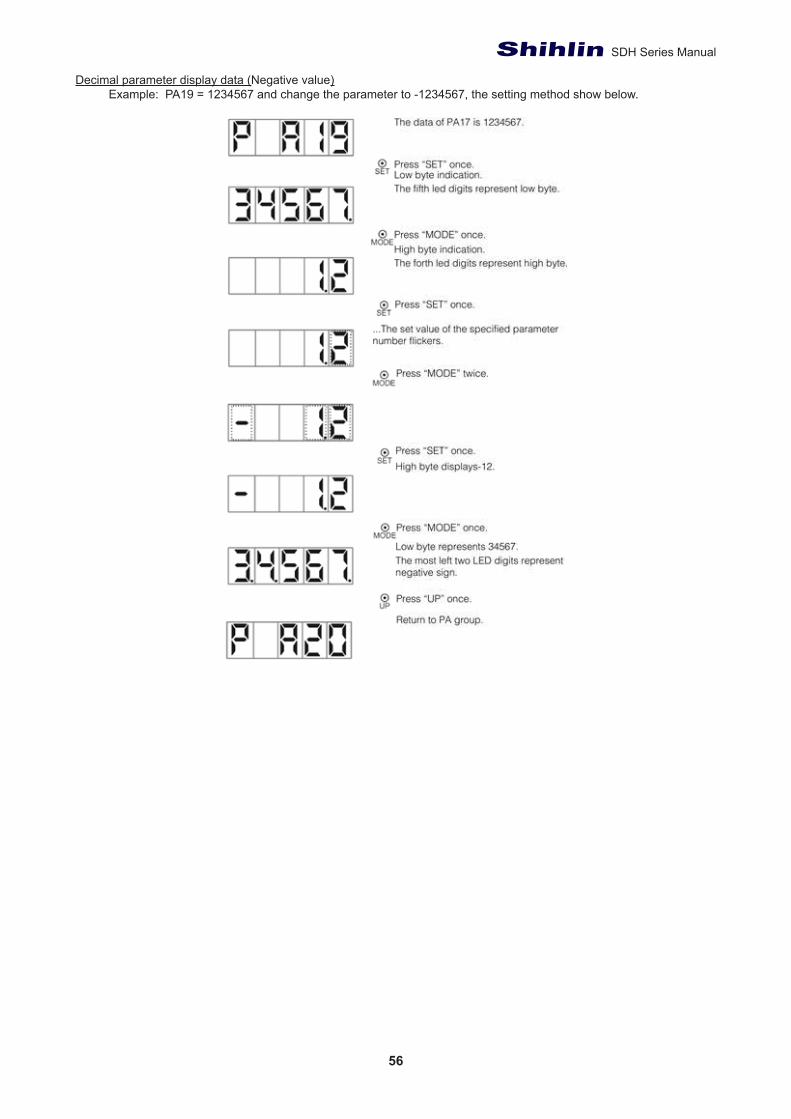
56
SDH Series Manual
Decimal parameter display data (Negative value) Example: PA19 = 1234567 and change the parameter to -1234567, the setting method show below.
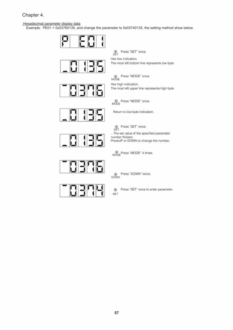
57
Chapter 4.
Hexadecimal parameter display data Example: PE01 = 0x03760135, and change the parameter to 0x03740135, the setting method show below.
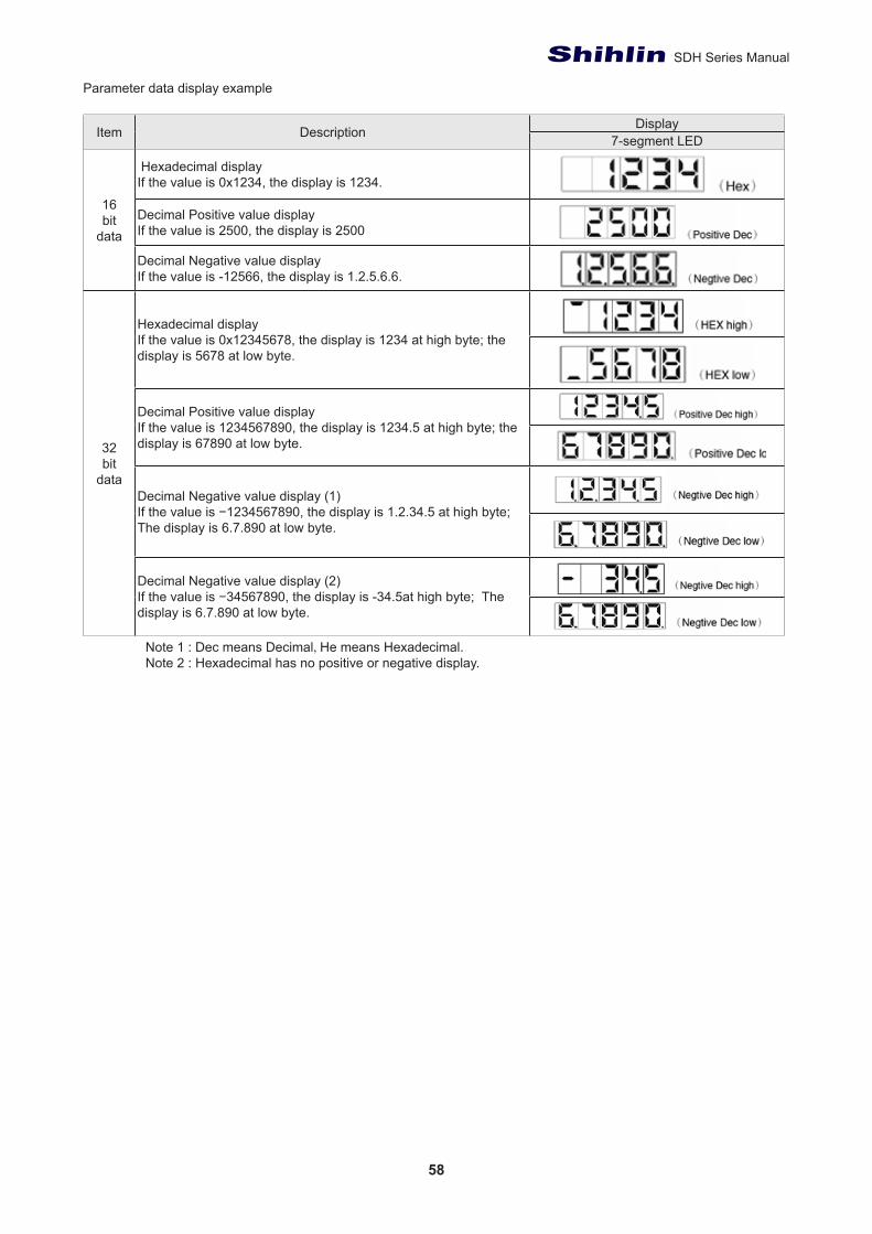
58
SDH Series Manual
Parameter data display example
Item Description Display7-segment LED
16bit
data
Hexadecimal displayIf the value is 0x1234, the display is 1234.
Decimal Positive value displayIf the value is 2500, the display is 2500
Decimal Negative value displayIf the value is -12566, the display is 1.2.5.6.6.
32bit
data
Hexadecimal displayIf the value is 0x12345678, the display is 1234 at high byte; the display is 5678 at low byte.
Decimal Positive value displayIf the value is 1234567890, the display is 1234.5 at high byte; the display is 67890 at low byte.
Decimal Negative value display (1)If the value is −1234567890, the display is 1.2.34.5 at high byte; The display is 6.7.890 at low byte.
Decimal Negative value display (2)If the value is −34567890, the display is -34.5at high byte; The display is 6.7.890 at low byte.
Note 1 : Dec means Decimal, He means Hexadecimal.Note 2 : Hexadecimal has no positive or negative display.
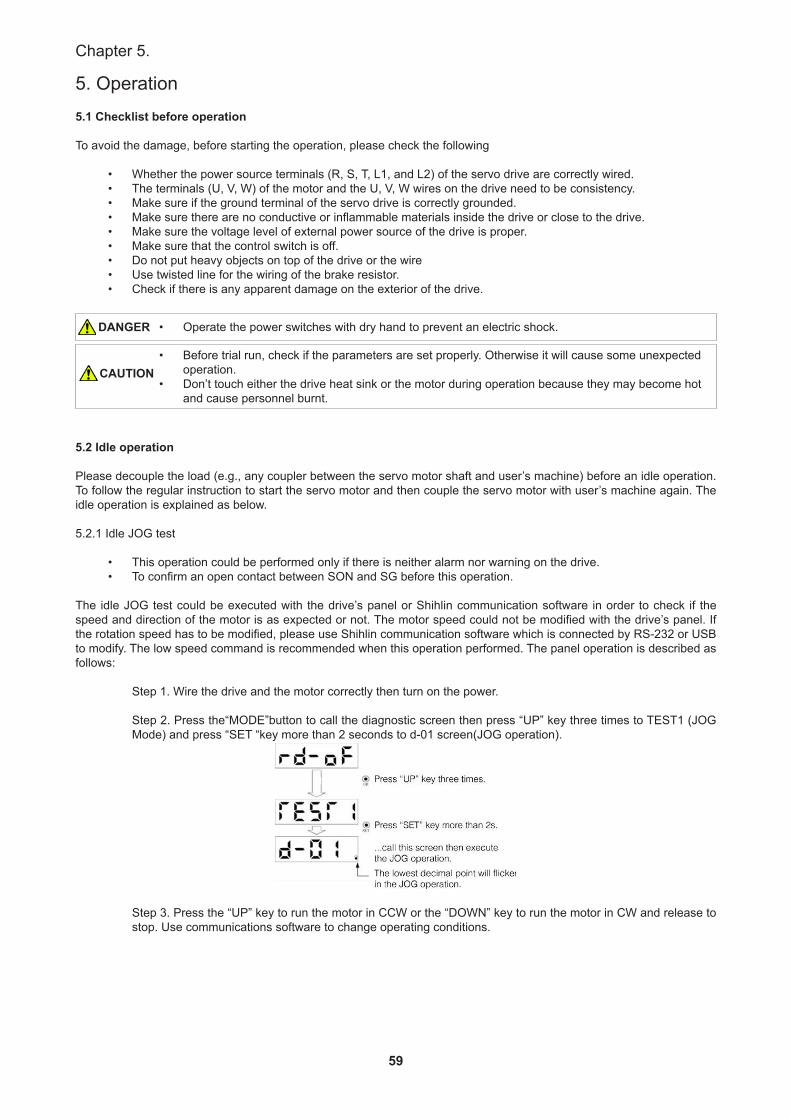
59
Chapter 5.
5. Operation
5.1 Checklist before operation
To avoid the damage, before starting the operation, please check the following
• Whether the power source terminals (R, S, T, L1, and L2) of the servo drive are correctly wired.• The terminals (U, V, W) of the motor and the U, V, W wires on the drive need to be consistency.• Make sure if the ground terminal of the servo drive is correctly grounded.• Make sure there are no conductive or inflammable materials inside the drive or close to the drive.• Make sure the voltage level of external power source of the drive is proper.• Make sure that the control switch is off.• Do not put heavy objects on top of the drive or the wire• Use twisted line for the wiring of the brake resistor.• Check if there is any apparent damage on the exterior of the drive.
• Operate the power switches with dry hand to prevent an electric shock.
• Before trial run, check if the parameters are set properly. Otherwise it will cause some unexpected operation.
• Don’t touch either the drive heat sink or the motor during operation because they may become hot and cause personnel burnt.
5.2 Idle operation
Please decouple the load (e.g., any coupler between the servo motor shaft and user’s machine) before an idle operation. To follow the regular instruction to start the servo motor and then couple the servo motor with user’s machine again. The idle operation is explained as below.
5.2.1 Idle JOG test
• This operation could be performed only if there is neither alarm nor warning on the drive.• To confirm an open contact between SON and SG before this operation.
The idle JOG test could be executed with the drive’s panel or Shihlin communication software in order to check if the speed and direction of the motor is as expected or not. The motor speed could not be modified with the drive’s panel. If the rotation speed has to be modified, please use Shihlin communication software which is connected by RS-232 or USB to modify. The low speed command is recommended when this operation performed. The panel operation is described as follows:
Step 1. Wire the drive and the motor correctly then turn on the power.
Step 2. Press the“MODE”button to call the diagnostic screen then press “UP” key three times to TEST1 (JOG Mode) and press “SET “key more than 2 seconds to d-01 screen(JOG operation).
Step 3. Press the “UP” key to run the motor in CCW or the “DOWN” key to run the motor in CW and release to stop. Use communications software to change operating conditions.
DANGER
CAUTION
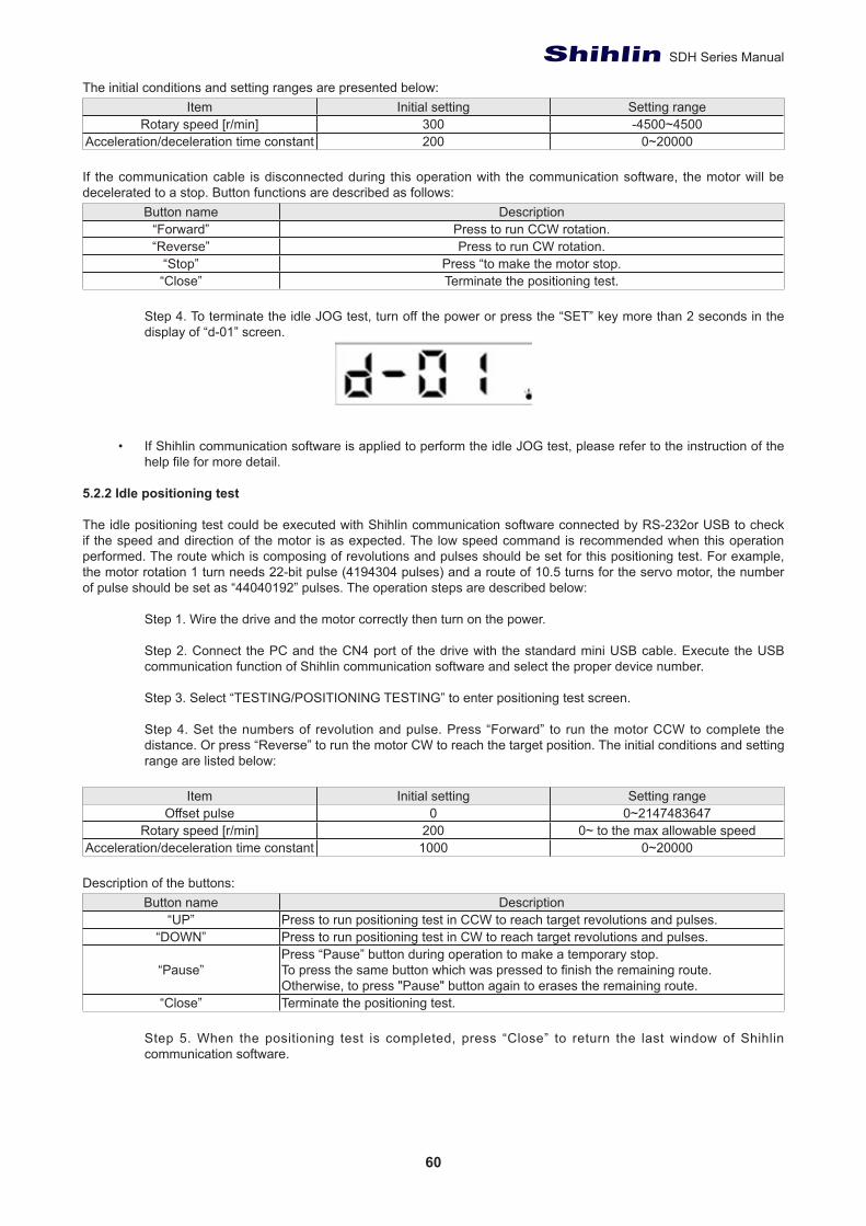
60
SDH Series Manual
The initial conditions and setting ranges are presented below:Item Initial setting Setting range
Rotary speed [r/min] 300 -4500~4500Acceleration/deceleration time constant 200 0~20000
If the communication cable is disconnected during this operation with the communication software, the motor will be decelerated to a stop. Button functions are described as follows:
Button name Description“Forward” Press to run CCW rotation.“Reverse” Press to run CW rotation.
“Stop” Press “to make the motor stop.“Close” Terminate the positioning test.
Step 4. To terminate the idle JOG test, turn off the power or press the “SET” key more than 2 seconds in the display of “d-01” screen.
• If Shihlin communication software is applied to perform the idle JOG test, please refer to the instruction of the help file for more detail.
5.2.2 Idle positioning test
The idle positioning test could be executed with Shihlin communication software connected by RS-232or USB to check if the speed and direction of the motor is as expected. The low speed command is recommended when this operation performed. The route which is composing of revolutions and pulses should be set for this positioning test. For example, the motor rotation 1 turn needs 22-bit pulse (4194304 pulses) and a route of 10.5 turns for the servo motor, the number of pulse should be set as “44040192” pulses. The operation steps are described below:
Step 1. Wire the drive and the motor correctly then turn on the power.
Step 2. Connect the PC and the CN4 port of the drive with the standard mini USB cable. Execute the USB communication function of Shihlin communication software and select the proper device number.
Step 3. Select “TESTING/POSITIONING TESTING” to enter positioning test screen.
Step 4. Set the numbers of revolution and pulse. Press “Forward” to run the motor CCW to complete the distance. Or press “Reverse” to run the motor CW to reach the target position. The initial conditions and setting range are listed below:
Item Initial setting Setting rangeOffset pulse 0 0~2147483647
Rotary speed [r/min] 200 0~ to the max allowable speedAcceleration/deceleration time constant 1000 0~20000
Description of the buttons:Button name Description
“UP” Press to run positioning test in CCW to reach target revolutions and pulses.“DOWN” Press to run positioning test in CW to reach target revolutions and pulses.
“Pause”Press “Pause” button during operation to make a temporary stop.To press the same button which was pressed to finish the remaining route.Otherwise, to press "Pause" button again to erases the remaining route.
“Close” Terminate the positioning test.
Step 5. When the positioning test is completed, press “Close” to return the last window of Shihlin communication software.
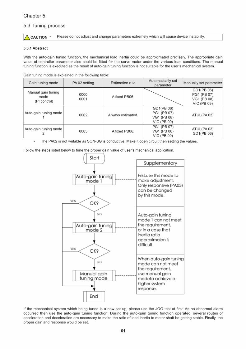
61
Chapter 5.
5.3 Tuning process
• Please do not adjust and change parameters extremely which will cause device instability.
5.3.1 Abstract
With the auto-gain tuning function, the mechanical load inertia could be approximated precisely. The appropriate gain value of controller parameter also could be fitted for the servo motor under the various load conditions. The manual tuning function is executed as the result of auto-gain tuning function is not suitable for the user’s mechanical system.
Gain tuning mode is explained in the following table:
Gain tuning mode PA 02 setting Estimation rule Automatically set parameter Manually set parameter
Manual gain tuning mode
(PI control)
00000001 A fixed PB06.
GD1(PB 06)PG1 (PB 07)VG1 (PB 08)VIC (PB 09)
Auto-gain tuning mode 1 0002 Always estimated.
GD1(PB 06)PG1 (PB 07)VG1 (PB 08)VIC (PB 09)
ATUL(PA 03)
Auto-gain tuning mode 2 0003 A fixed PB06.
PG1 (PB 07)VG1 (PB 08)VIC (PB 09)
ATUL(PA 03)GD1(PB 06)
• The PA02 is not writable as SON-SG is conductive. Make it open circuit then setting the values.
Follow the steps listed below to tune the proper gain value of user’s mechanical application.
If the mechanical system which being tuned is a new set up, please use the JOG test at first. As no abnormal alarm occurred then use the auto-gain tuning function. During the auto-gain tuning function operated, several routes of acceleration and deceleration are necessary to make the ratio of load inertia to motor shaft be getting stable. Finally, the proper gain and response would be set.
CAUTION
62
SDH Series Manual
5.3.2 Auto-gain tuning mode
The auto-gain tuning of the drive could calculate the ratio of load inertia to motor shaft instantaneously. With this value, the optimum gain could be decided under the current mechanical condition. It is convenient to execute the adjustment of gain value with the auto-gain tuning function.
5.3.2.1 Auto-gain tuning function
(1) Auto-gain tuning mode1This mode is the default mode of the servo drive. If the parameter PA02 is set as “0002h”, the load inertia ratio would be approximated continuously and the servo gain value will be set automatically. The variable parameter for users is only PA03 which the response setting related.
Parameters and settings related of this mode are presented below:Parameter NO Abbr Parameter name User adjustable or auto-presumed
PA 03 ATUL Auto-tuning response level setting User adjustablePB 06 GD1 The ratio of load inertia to motor shaft auto-approximated PB 07 PG1 Position loop gain auto-approximatedPB 08 VG1 Speed loop gain auto-approximatedPB 09 VIC Speed integral gain auto-approximated
When the function of auto-gain tuning mode 1 is applied, some conditions must be met.• The acceleration time from 0rpm to 2000rpm or the deceleration time from 2000rpm to 0rpm should be 2
second or less. If a 3000rpm case is applied, the acceleration and deceleration time should be 3 seconds or less.
• The speed command of the motor should be 250rpm or higher.• The ratio of machinery load inertia to motor shaft should be 100 times or less.• The machinery system with a violent change of load inertia is not suitable.• The acceleration/deceleration torque is more than rated torque 10% or above.
(2)Auto-gain tuning mode 2When auto-gain tuning mode 1 is not satisfied the accurate approximation of load inertia, the auto-gain tuning mode 2 is recommended. The parameter PA02 should be set as “0003h” to perform this mode. During the tun-ing process, the load inertia ratio would not be approximated and the users have to write manually the value into PB06 by themselves.
Parameters and settings related of this mode are presented below:Parameter NO Abbr Parameter name User adjustable or auto-presumed
PA 03 ATUL Auto-tuning response level setting User adjustable PB 06 GD1 The ratio of load inertia to motor shaft User adjustable PB 07 PG1 Position loop gain auto-approximated PB 08 VG1 Speed loop gain auto-approximated PB 09 VIC Speed integral gain auto-approximated
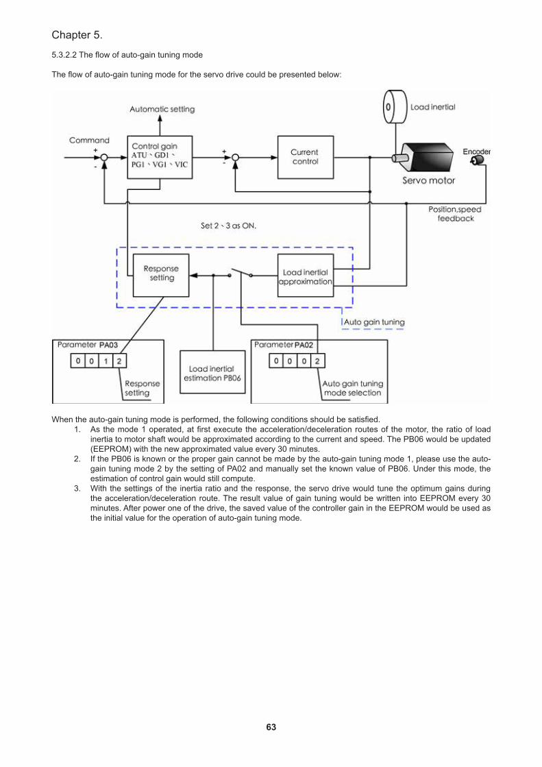
63
Chapter 5.
5.3.2.2 The flow of auto-gain tuning mode
The flow of auto-gain tuning mode for the servo drive could be presented below:
When the auto-gain tuning mode is performed, the following conditions should be satisfied.1. As the mode 1 operated, at first execute the acceleration/deceleration routes of the motor, the ratio of load
inertia to motor shaft would be approximated according to the current and speed. The PB06 would be updated (EEPROM) with the new approximated value every 30 minutes.
2. If the PB06 is known or the proper gain cannot be made by the auto-gain tuning mode 1, please use the auto-gain tuning mode 2 by the setting of PA02 and manually set the known value of PB06. Under this mode, the estimation of control gain would still compute.
3. With the settings of the inertia ratio and the response, the servo drive would tune the optimum gains during the acceleration/deceleration route. The result value of gain tuning would be written into EEPROM every 30 minutes. After power one of the drive, the saved value of the controller gain in the EEPROM would be used as the initial value for the operation of auto-gain tuning mode.
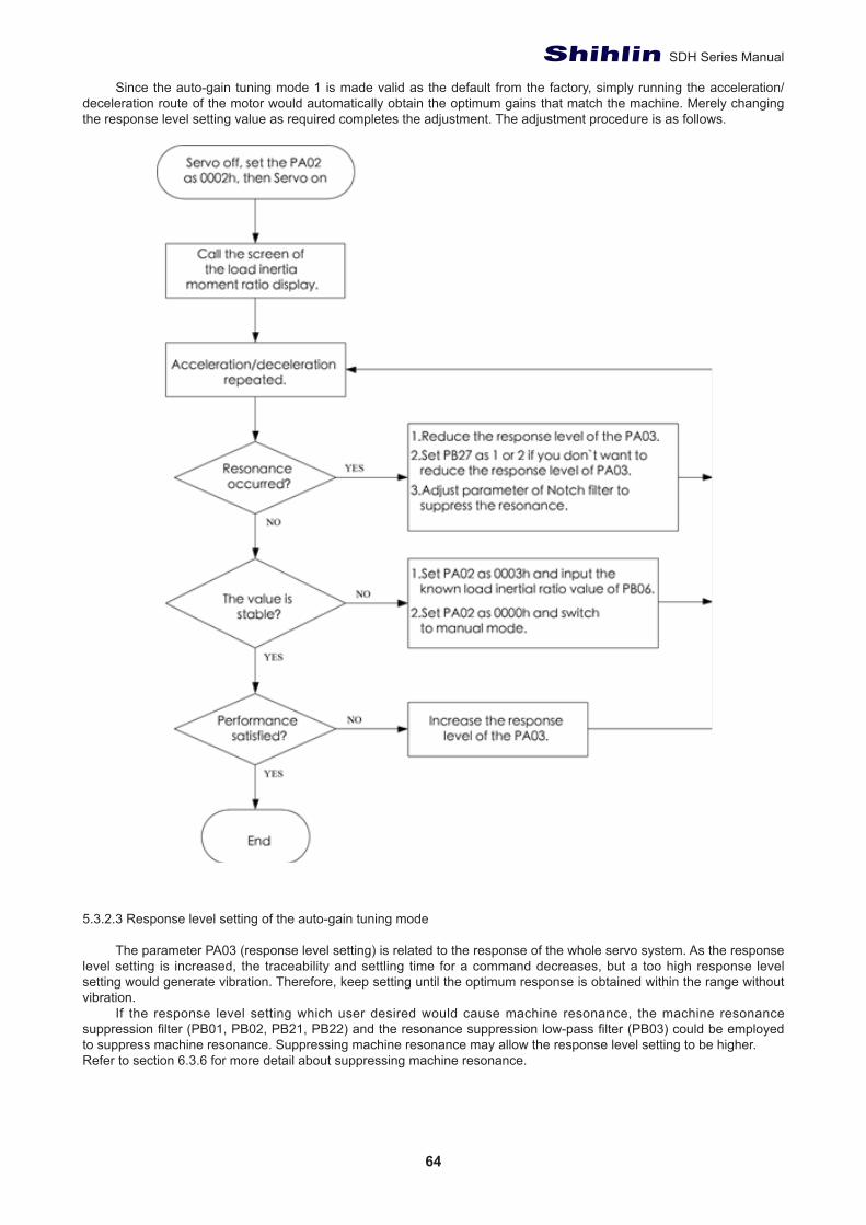
64
SDH Series Manual
Since the auto-gain tuning mode 1 is made valid as the default from the factory, simply running the acceleration/deceleration route of the motor would automatically obtain the optimum gains that match the machine. Merely changing the response level setting value as required completes the adjustment. The adjustment procedure is as follows.
5.3.2.3 Response level setting of the auto-gain tuning mode
The parameter PA03 (response level setting) is related to the response of the whole servo system. As the response level setting is increased, the traceability and settling time for a command decreases, but a too high response level setting would generate vibration. Therefore, keep setting until the optimum response is obtained within the range without vibration.
If the response level setting which user desired would cause machine resonance, the machine resonance suppression filter (PB01, PB02, PB21, PB22) and the resonance suppression low-pass filter (PB03) could be employed to suppress machine resonance. Suppressing machine resonance may allow the response level setting to be higher.Refer to section 6.3.6 for more detail about suppressing machine resonance.

65
Chapter 5.
Response level setting Machine rigidity
Speed loop response
frequency (Hz)
Response level setting Machine rigidity
Speed loop response
frequency (Hz)1
Low
Middle
10.0 17Middle
High
67.12 11.3 18 75.63 12.7 19 85.24 14.3 20 95.95 16.1 21 108.06 18.1 22 121.77 20.4 23 137.18 23.0 24 154.49 25.9 25 173.9
10 29.2 26 195.911 32.9 27 220.612 37.0 28 248.513 41.7 29 279.914 47.0 30 315.315 52.9 31 355.116 59.6 32 400.0
• For the response level setting, it is recommended to use the level value from low response to high response gradually. It is probable to make resonance if the initial value is too high.
• The applicable ratio of load inertia to motor shaft is a reference. The actual range would vary with the different mechanical systems.
5.3.3 Manual gain tuning mode
The manual gain tuning mode is executed as the result of auto-gain tuning function is not suitable for the user’s demand.
Adjustment of manual modeFor the applications of position control or speed control, the bandwidth is highly related with themachinery rigidity
and environment. For machine tools which the high precision required, a high Bandwidth system response is necessary. However, a high response level setting could cause the machine resonance easily. Therefore, a high rigidity machine should be used for occasions that require a high response to avoid machine resonance.
If users have no idea about the permissible response of the machine, they should adopt a smaller gain value at first and then gradually increase the gain values until machine resonance occurred. Then users could reduce the gain values accordingly. Reference parameter values for users to adjustare listed in the following table:
Name Abbr. Sign Setting range Unit Initialvalue
Controlmode
Resonance suppression low-pass filter NLP PB03 0~10000 0.1ms 10 ALLPosition feed-forward gain value FFC PB05 0~200 % 0 Pt、Pr
The ratio of load inertia to motor shaft GD1 PB06 0~1200 0.1 time 70 ALLPosition loop gain PG1 PB07 4~1024 rad/s 45 Pt、PrSpeed loop gain VG1 PB08 40~9000 rad/s 183 ALL
Speed integral gain VIC PB09 1~1000 ms 34 ALLSpeed feed-forward gain VFG PB10 0~200 % 0 S、T
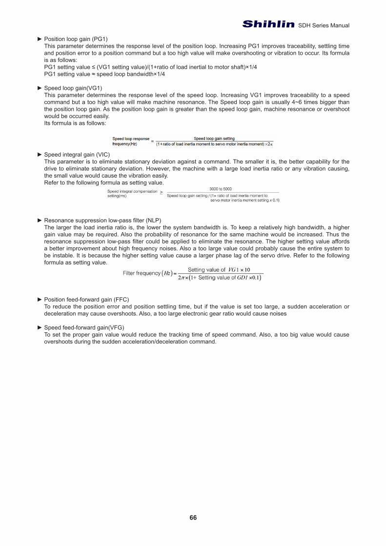
66
SDH Series Manual
► Position loop gain (PG1)This parameter determines the response level of the position loop. Increasing PG1 improves traceability, settling time and position error to a position command but a too high value will make overshooting or vibration to occur. Its formula is as follows:PG1 setting value ≤ (VG1 setting value)/(1+ratio of load inertial to motor shaft)×1/4PG1 setting value ≈ speed loop bandwidth×1/4
► Speed loop gain(VG1)This parameter determines the response level of the speed loop. Increasing VG1 improves traceability to a speed command but a too high value will make machine resonance. The Speed loop gain is usually 4~6 times bigger than the position loop gain. As the position loop gain is greater than the speed loop gain, machine resonance or overshoot would be occurred easily. Its formula is as follows:
► Speed integral gain (VIC)This parameter is to eliminate stationary deviation against a command. The smaller it is, the better capability for the drive to eliminate stationary deviation. However, the machine with a large load inertia ratio or any vibration causing, the small value would cause the vibration easily. Refer to the following formula as setting value.
► Resonance suppression low-pass filter (NLP)The larger the load inertia ratio is, the lower the system bandwidth is. To keep a relatively high bandwidth, a higher gain value may be required. Also the probability of resonance for the same machine would be increased. Thus the resonance suppression low-pass filter could be applied to eliminate the resonance. The higher setting value affords a better improvement about high frequency noises. Also a too large value could probably cause the entire system to be instable. It is because the higher setting value cause a larger phase lag of the servo drive. Refer to the following formula as setting value.
► Position feed-forward gain (FFC)To reduce the position error and position settling time, but if the value is set too large, a sudden acceleration or deceleration may cause overshoots. Also, a too large electronic gear ratio would cause noises
► Speed feed-forward gain(VFG)To set the proper gain value would reduce the tracking time of speed command. Also, a too big value would cause overshoots during the sudden acceleration/deceleration command.
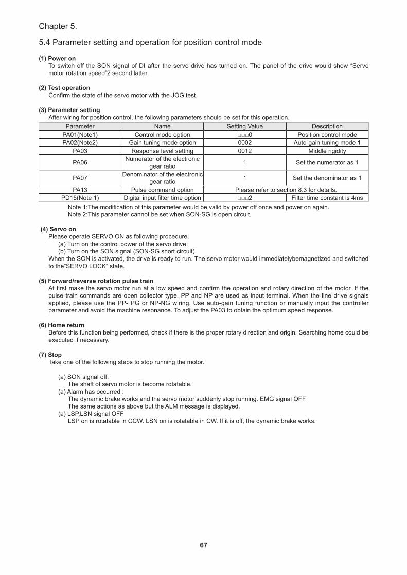
67
Chapter 5.
5.4 Parameter setting and operation for position control mode
(1) Power onTo switch off the SON signal of DI after the servo drive has turned on. The panel of the drive would show “Servo motor rotation speed”2 second latter.
(2) Test operationConfirm the state of the servo motor with the JOG test.
(3) Parameter settingAfter wiring for position control, the following parameters should be set for this operation.
Parameter Name Setting Value DescriptionPA01(Note1) Control mode option □□□0 Position control modePA02(Note2) Gain tuning mode option 0002 Auto-gain tuning mode 1
PA03 Response level setting 0012 Middle rigidity
PA06 Numerator of the electronic gear ratio 1 Set the numerator as 1
PA07 Denominator of the electronic gear ratio 1 Set the denominator as 1
PA13 Pulse command option Please refer to section 8.3 for details.PD15(Note 1) Digital input filter time option □□□2 Filter time constant is 4ms
Note 1:The modification of this parameter would be valid by power off once and power on again.Note 2:This parameter cannot be set when SON-SG is open circuit.
(4) Servo onPlease operate SERVO ON as following procedure.
(a) Turn on the control power of the servo drive.(b) Turn on the SON signal (SON-SG short circuit).
When the SON is activated, the drive is ready to run. The servo motor would immediatelybemagnetized and switched to the”SERVO LOCK” state.
(5) Forward/reverse rotation pulse trainAt first make the servo motor run at a low speed and confirm the operation and rotary direction of the motor. If the pulse train commands are open collector type, PP and NP are used as input terminal. When the line drive signals applied, please use the PP- PG or NP-NG wiring. Use auto-gain tuning function or manually input the controller parameter and avoid the machine resonance. To adjust the PA03 to obtain the optimum speed response.
(6) Home returnBefore this function being performed, check if there is the proper rotary direction and origin. Searching home could be executed if necessary.
(7) StopTake one of the following steps to stop running the motor.
(a) SON signal off:The shaft of servo motor is become rotatable.
(a) Alarm has occurred :The dynamic brake works and the servo motor suddenly stop running. EMG signal OFFThe same actions as above but the ALM message is displayed.
(a) LSP,LSN signal OFFLSP on is rotatable in CCW. LSN on is rotatable in CW. If it is off, the dynamic brake works.
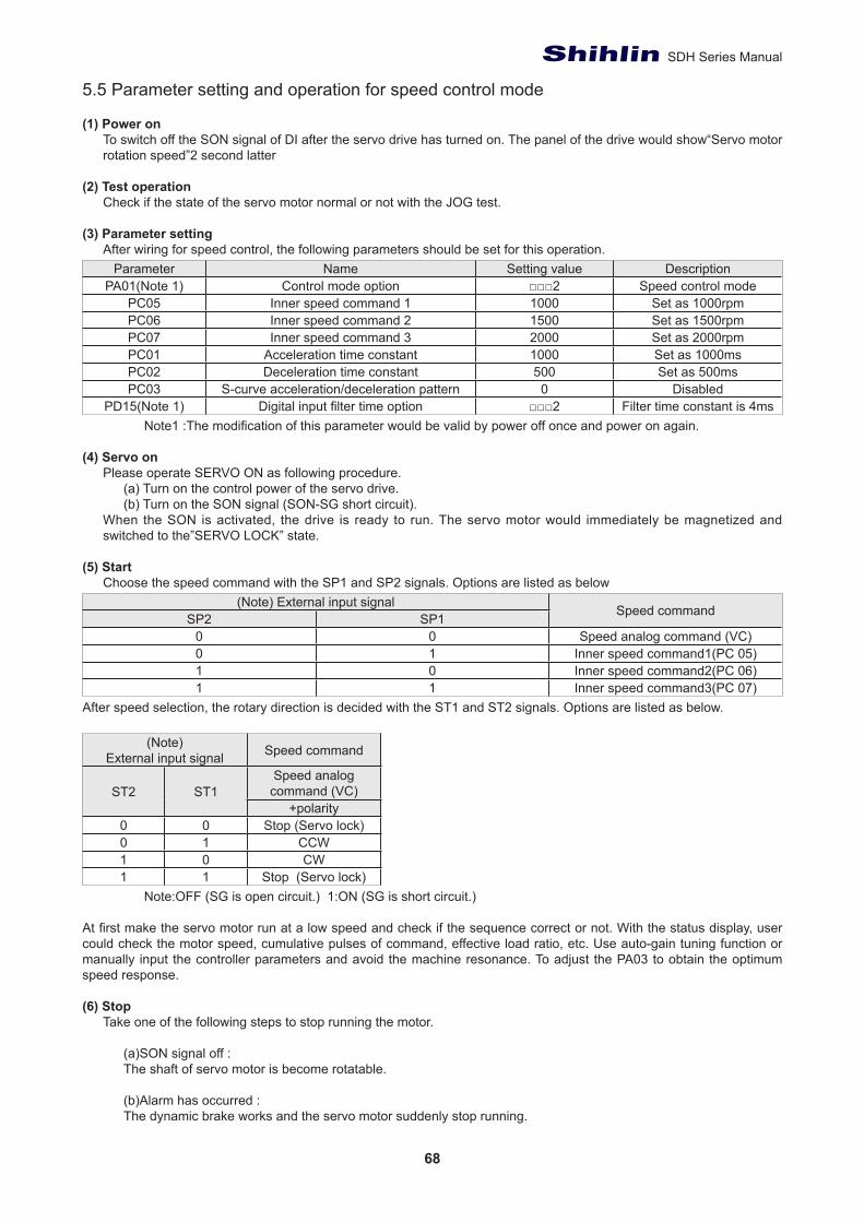
68
SDH Series Manual
5.5 Parameter setting and operation for speed control mode
(1) Power onTo switch off the SON signal of DI after the servo drive has turned on. The panel of the drive would show“Servo motor rotation speed”2 second latter
(2) Test operationCheck if the state of the servo motor normal or not with the JOG test.
(3) Parameter settingAfter wiring for speed control, the following parameters should be set for this operation.
Parameter Name Setting value DescriptionPA01(Note 1) Control mode option □□□2 Speed control mode
PC05 Inner speed command 1 1000 Set as 1000rpmPC06 Inner speed command 2 1500 Set as 1500rpmPC07 Inner speed command 3 2000 Set as 2000rpmPC01 Acceleration time constant 1000 Set as 1000msPC02 Deceleration time constant 500 Set as 500msPC03 S-curve acceleration/deceleration pattern 0 Disabled
PD15(Note 1) Digital input filter time option □□□2 Filter time constant is 4msNote1 :The modification of this parameter would be valid by power off once and power on again.
(4) Servo onPlease operate SERVO ON as following procedure.
(a) Turn on the control power of the servo drive.(b) Turn on the SON signal (SON-SG short circuit).
When the SON is activated, the drive is ready to run. The servo motor would immediately be magnetized and switched to the”SERVO LOCK” state.
(5) StartChoose the speed command with the SP1 and SP2 signals. Options are listed as below
(Note) External input signal Speed commandSP2 SP10 0 Speed analog command (VC)0 1 Inner speed command1(PC 05)1 0 Inner speed command2(PC 06)1 1 Inner speed command3(PC 07)
After speed selection, the rotary direction is decided with the ST1 and ST2 signals. Options are listed as below.
(Note)External input signal Speed command
ST2 ST1Speed analog command (VC)
+polarity0 0 Stop (Servo lock)0 1 CCW1 0 CW1 1 Stop (Servo lock)
Note:OFF (SG is open circuit.) 1:ON (SG is short circuit.)
At first make the servo motor run at a low speed and check if the sequence correct or not. With the status display, user could check the motor speed, cumulative pulses of command, effective load ratio, etc. Use auto-gain tuning function or manually input the controller parameters and avoid the machine resonance. To adjust the PA03 to obtain the optimum speed response.
(6) StopTake one of the following steps to stop running the motor.
(a)SON signal off :The shaft of servo motor is become rotatable.
(b)Alarm has occurred :The dynamic brake works and the servo motor suddenly stop running.
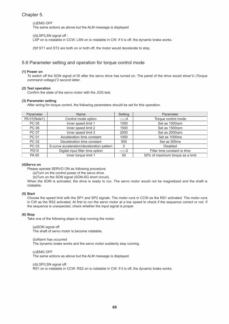
69
Chapter 5.
(c)EMG OFFThe same actions as above but the ALM message is displayed
(d)LSP/LSN signal off :LSP on is rotatable in CCW. LSN on is rotatable in CW. If it is off, the dynamic brake works.
(f)If ST1 and ST2 are both on or both off, the motor would decelerate to stop.
5.6 Parameter setting and operation for torque control mode
(1) Power onTo switch off the SON signal of DI after the servo drive has turned on. The panel of the drive would show“U (Torque command voltage)”2 second latter.
(2) Test operationConfirm the state of the servo motor with the JOG test.
(3) Parameter settingAfter wiring for torque control, the following parameters should be set for this operation.
Parameter Name Setting ParameterPA 01(Note1) Control mode option □□□4 Torque control mode
PC 05 Inner speed limit 1 1000 Set as 1000rpmPC 06 Inner speed limit 2 1500 Set as 1500rpmPC 07 Inner speed limit 3 2000 Set as 2000rpmPC 01 Acceleration time constant 1000 Set as 1000msPC 02 Deceleration time constant 500 Set as 500msPC 03 S-curve acceleration/deceleration pattern 0 DisabledPD15 Digital input filter time option □□□2 Filter time constant is 4msPA 05 Inner torque limit 1 50 50% of maximum torque as a limit
(4)Servo onPlease operate SERVO ON as following procedure.
(a)Turn on the control power of the servo drive.(b)Turn on the SON signal (SON-SG short circuit).
When the SON is activated, the drive is ready to run. The servo motor would not be magnetized and the shaft is rotatable.
(5) StartChoose the speed limit with the SP1 and SP2 signals. The motor runs in CCW as the RS1 activated. The motor runs in CW as the RS2 activated. At first to run the servo motor at a low speed to check if the sequence correct or not. If the sequence is unexpected, check whether the input signal is proper.
(6) StopTake one of the following steps to stop running the motor.
(a)SON signal offThe shaft of servo motor is become rotatable.
(b)Alarm has occurredThe dynamic brake works and the servo motor suddenly stop running.
(c)EMG OFFThe same actions as above but the ALM message is displayed.
(d)LSP/LSN signal off:RS1 on is rotatable in CCW. RS2 on is rotatable in CW. If it is off, the dynamic brake works.
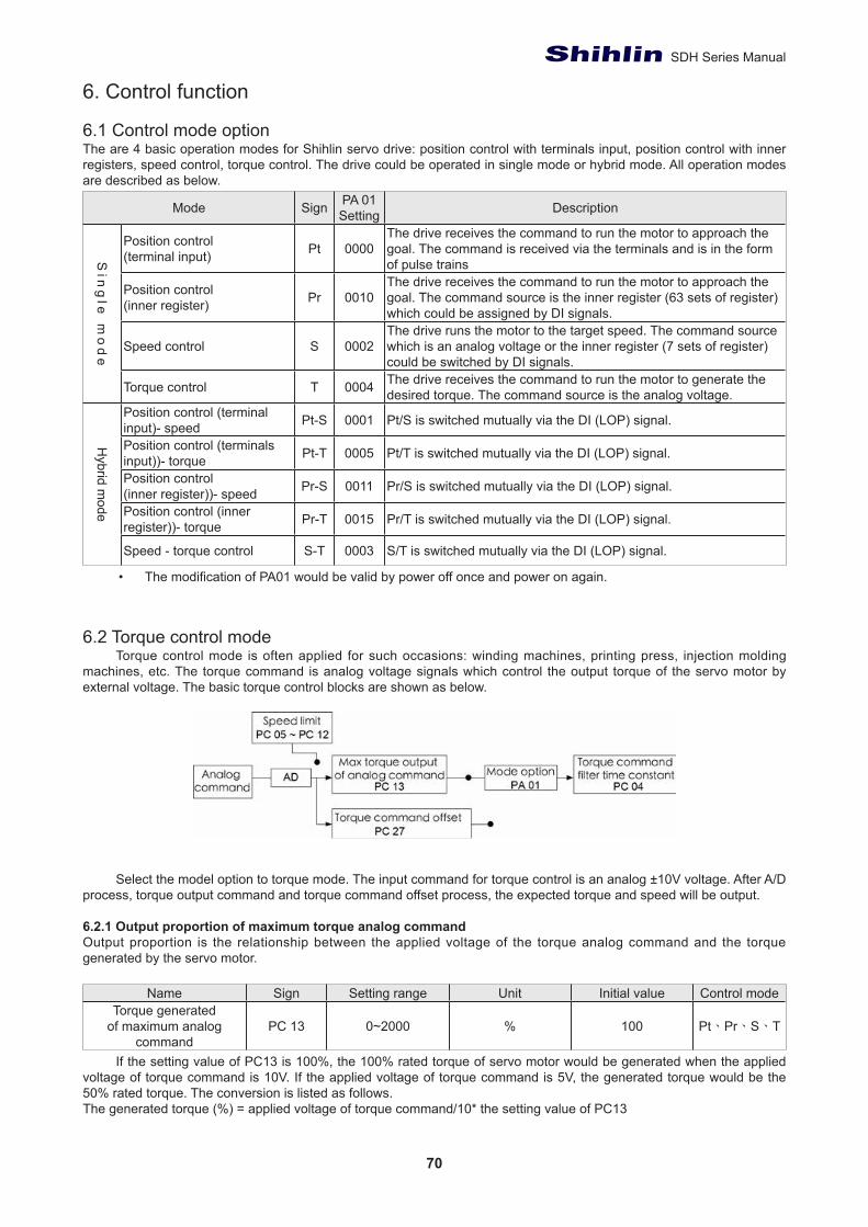
70
SDH Series Manual
6. Control function
6.1 Control mode optionThe are 4 basic operation modes for Shihlin servo drive: position control with terminals input, position control with inner registers, speed control, torque control. The drive could be operated in single mode or hybrid mode. All operation modes are described as below.
Mode Sign PA 01 Setting Description
Sin
gle
mo
de
Position control(terminal input) Pt 0000
The drive receives the command to run the motor to approach the goal. The command is received via the terminals and is in the form of pulse trains
Position control(inner register) Pr 0010
The drive receives the command to run the motor to approach the goal. The command source is the inner register (63 sets of register) which could be assigned by DI signals.
Speed control S 0002The drive runs the motor to the target speed. The command source which is an analog voltage or the inner register (7 sets of register) could be switched by DI signals.
Torque control T 0004 The drive receives the command to run the motor to generate the desired torque. The command source is the analog voltage.
Hybrid m
ode
Position control (terminal input)- speed Pt-S 0001 Pt/S is switched mutually via the DI (LOP) signal.
Position control (terminals input))- torque Pt-T 0005 Pt/T is switched mutually via the DI (LOP) signal.
Position control (inner register))- speed Pr-S 0011 Pr/S is switched mutually via the DI (LOP) signal.
Position control (inner register))- torque Pr-T 0015 Pr/T is switched mutually via the DI (LOP) signal.
Speed - torque control S-T 0003 S/T is switched mutually via the DI (LOP) signal.
• The modification of PA01 would be valid by power off once and power on again.
6.2 Torque control modeTorque control mode is often applied for such occasions: winding machines, printing press, injection molding
machines, etc. The torque command is analog voltage signals which control the output torque of the servo motor by external voltage. The basic torque control blocks are shown as below.
Select the model option to torque mode. The input command for torque control is an analog ±10V voltage. After A/D process, torque output command and torque command offset process, the expected torque and speed will be output.
6.2.1 Output proportion of maximum torque analog commandOutput proportion is the relationship between the applied voltage of the torque analog command and the torque generated by the servo motor.
Name Sign Setting range Unit Initial value Control modeTorque generated
of maximum analog command
PC 13 0~2000 % 100 Pt、Pr、S、T
If the setting value of PC13 is 100%, the 100% rated torque of servo motor would be generated when the applied voltage of torque command is 10V. If the applied voltage of torque command is 5V, the generated torque would be the 50% rated torque. The conversion is listed as follows.The generated torque (%) = applied voltage of torque command/10* the setting value of PC13
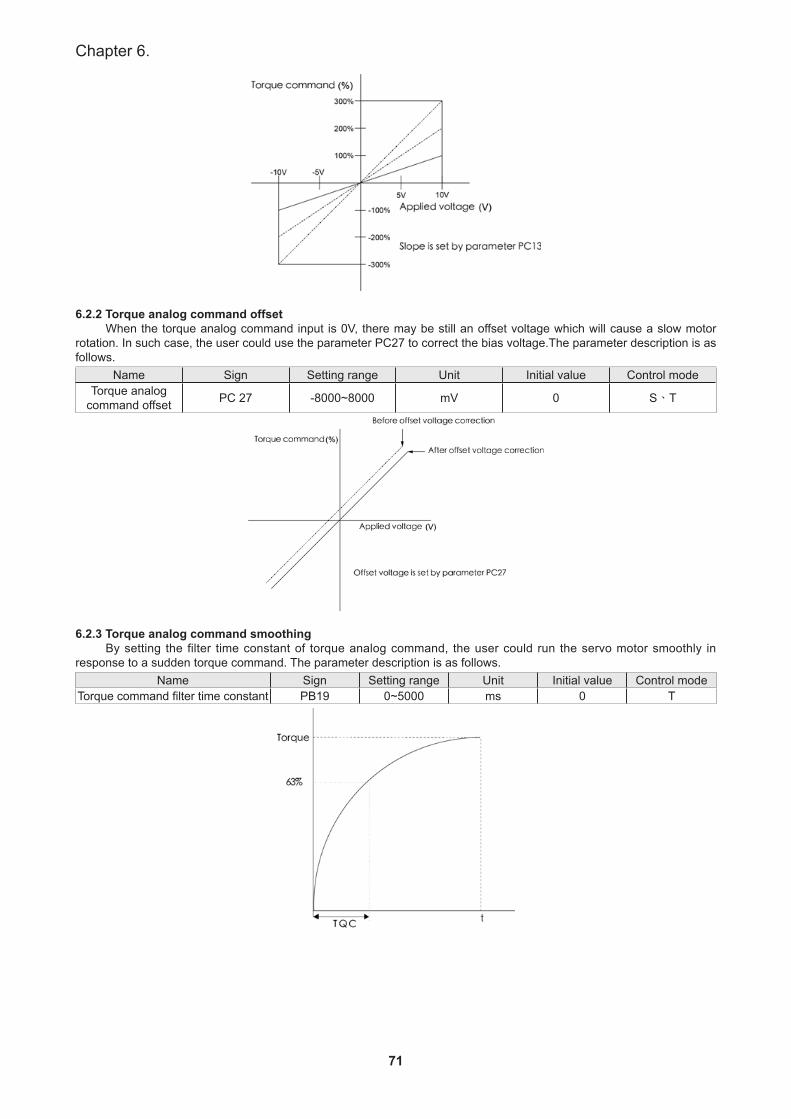
71
Chapter 6.
6.2.2 Torque analog command offsetWhen the torque analog command input is 0V, there may be still an offset voltage which will cause a slow motor
rotation. In such case, the user could use the parameter PC27 to correct the bias voltage.The parameter description is as follows.
Name Sign Setting range Unit Initial value Control modeTorque analog
command offset PC 27 -8000~8000 mV 0 S、T
6.2.3 Torque analog command smoothingBy setting the filter time constant of torque analog command, the user could run the servo motor smoothly in
response to a sudden torque command. The parameter description is as follows.Name Sign Setting range Unit Initial value Control mode
Torque command filter time constant PB19 0~5000 ms 0 T
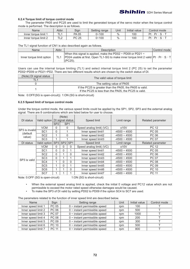
72
SDH Series Manual
6.2.4 Torque limit of torque control modeThe parameter PA05 and PC25 are used to limit the generated torque of the servo motor when the torque control
mode is performed. The description is as follows.Name Abbr. Sign Setting range Unit Initial value Control mode
Inner torque limit 1 TL1 PA 05 0~100 % 100 Pt、Pr、S、TInner torque limit 2 TL2 PC 25 0~100 % 100 Pt、Pr、S、T
The TL1 signal function of CN1 is also described again as follows.Name Abbr. Description Control mode
Inner torque limit option TL1When this signal is applied, make the PD02 ~ PD09 or PD21 ~ PD24 usable at first. Open TL1-SG to make inner torque limit 2 valid (PC25).
Pt、Pr、S、T
Users can use the internal torque limiting (TL1) and select internal torque limit 2 (PC 25) to set the parameter PD02~PD09 or PD21~PD2. There are two different results which are chosen by the switch status of DI.
(Note) DI signal status The valid value of torque limitTL10 The setting value of PA05
1 If the PC25 is greater than the PA05, the PA05 is valid.If the PC25 is less than the PA05, the PC25 is valid.
Note: 0:OFF(SG is open-circuit)) 1:ON (SG is short-circuit) 6.2.5 Speed limit of torque control mode
Under the torque control mode, the various speed limits could be applied by the SP1, SP2, SP3 and the external analog signal. There are 8 combinations which are listed below for user to choose.
DI status Valid option(Note)
DI signal status Speed limit Limit range Related parameterSP2 SP1
SP3 is invalid(default value)
VCM 0 0 Speed analog limit( (VC) ±10V PC 12SC1 0 1 Inner speed limit1 -4500 ~ 4500 PC 05SC2 1 0 Inner speed limit2 -4500 ~ 4500 PC 06SC3 1 1 Inner speed limit3 -4500 ~ 4500 PC 07
DI status Valid option SP3 SP2 SP1 Speed limit Limit range Related parameter
SP3 is valid
VCM 0 0 0 Speed analog limit( (VC) ±10V PC 12SC1 0 0 1 Inner speed limit1 -4500 ~ 4500 PC 05SC2 0 1 0 Inner speed limit2 -4500 ~ 4500 PC 06SC3 0 1 1 Inner speed limit3 -4500 ~ 4500 PC 07SC4 1 0 0 Inner speed limit4 -4500 ~ 4500 PC 08SC5 1 0 1 Inner speed limit5 -4500 ~ 4500 PC 09SC6 1 1 0 Inner speed limit6 -4500 ~ 4500 PC 10SC7 1 1 1 Inner speed limit7 -4500 ~ 4500 PC 11
Note: 0:OFF (SG is open-circuit) 1:ON (SG is short-circuit)
• When the external speed analog limit is applied, check the initial 0 voltage and PC12 value which are not permissible to exceed the motor rated speed otherwise damages would be caused.
• To make the SP3 of DI valid by setting PD02 to PD09 if the option SC4 to SC7 are used.
The parameters related to the function of inner speed limit are described below.Name Sign Setting range Unit Initial value Control mode
Inner speed limit 1 PC 05 0 ~ instant permissible speed rpm 100 TInner speed limit 2 PC 06 0 ~ instant permissible speed rpm 500 TInner speed limit 3 PC 07 0 ~ instant permissible speed rpm 1000 TInner speed limit 4 PC 08 0 ~ instant permissible speed rpm 200 TInner speed limit 5 PC 09 0 ~ instant permissible speed rpm 300 TInner speed limit 6 PC 10 0 ~ instant permissible speed rpm 500 TInner speed limit 7 PC 11 0 ~ instant permissible speed rpm 800 T
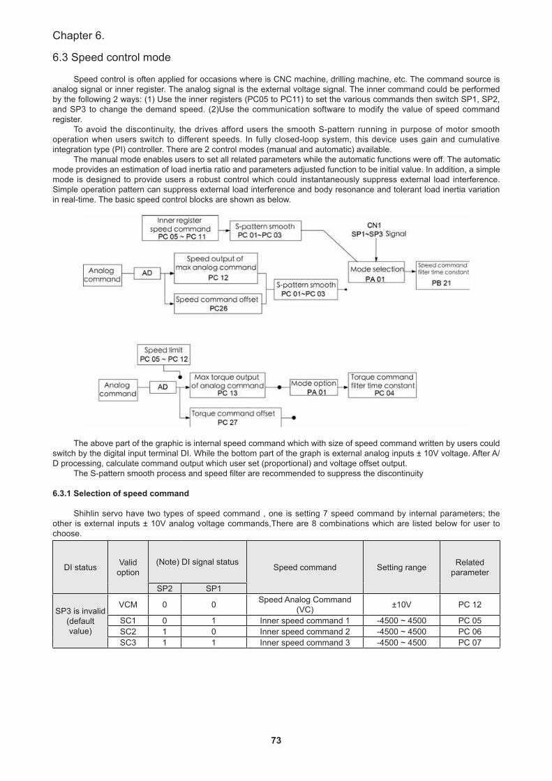
73
Chapter 6.
6.3 Speed control mode
Speed control is often applied for occasions where is CNC machine, drilling machine, etc. The command source is analog signal or inner register. The analog signal is the external voltage signal. The inner command could be performed by the following 2 ways: (1) Use the inner registers (PC05 to PC11) to set the various commands then switch SP1, SP2, and SP3 to change the demand speed. (2)Use the communication software to modify the value of speed command register.
To avoid the discontinuity, the drives afford users the smooth S-pattern running in purpose of motor smooth operation when users switch to different speeds. In fully closed-loop system, this device uses gain and cumulative integration type (PI) controller. There are 2 control modes (manual and automatic) available.
The manual mode enables users to set all related parameters while the automatic functions were off. The automatic mode provides an estimation of load inertia ratio and parameters adjusted function to be initial value. In addition, a simple mode is designed to provide users a robust control which could instantaneously suppress external load interference. Simple operation pattern can suppress external load interference and body resonance and tolerant load inertia variation in real-time. The basic speed control blocks are shown as below.
The above part of the graphic is internal speed command which with size of speed command written by users could switch by the digital input terminal DI. While the bottom part of the graph is external analog inputs ± 10V voltage. After A/D processing, calculate command output which user set (proportional) and voltage offset output.
The S-pattern smooth process and speed filter are recommended to suppress the discontinuity
6.3.1 Selection of speed command
Shihlin servo have two types of speed command , one is setting 7 speed command by internal parameters; the other is external inputs ± 10V analog voltage commands,There are 8 combinations which are listed below for user to choose.
DI status Valid option
(Note) DI signal status Speed command Setting range Related parameter
SP2 SP1
SP3 is invalid(default value)
VCM 0 0 Speed Analog Command(VC) ±10V PC 12
SC1 0 1 Inner speed command 1 -4500 ~ 4500 PC 05SC2 1 0 Inner speed command 2 -4500 ~ 4500 PC 06SC3 1 1 Inner speed command 3 -4500 ~ 4500 PC 07
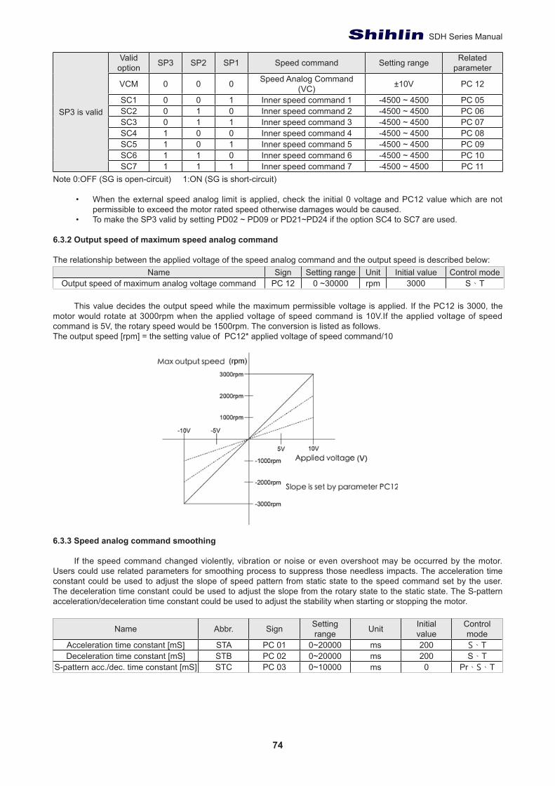
74
SDH Series Manual
SP3 is valid
Valid option SP3 SP2 SP1 Speed command Setting range Related
parameter
VCM 0 0 0 Speed Analog Command(VC) ±10V PC 12
SC1 0 0 1 Inner speed command 1 -4500 ~ 4500 PC 05SC2 0 1 0 Inner speed command 2 -4500 ~ 4500 PC 06SC3 0 1 1 Inner speed command 3 -4500 ~ 4500 PC 07SC4 1 0 0 Inner speed command 4 -4500 ~ 4500 PC 08SC5 1 0 1 Inner speed command 5 -4500 ~ 4500 PC 09SC6 1 1 0 Inner speed command 6 -4500 ~ 4500 PC 10SC7 1 1 1 Inner speed command 7 -4500 ~ 4500 PC 11
Note 0:OFF (SG is open-circuit) 1:ON (SG is short-circuit)
• When the external speed analog limit is applied, check the initial 0 voltage and PC12 value which are not permissible to exceed the motor rated speed otherwise damages would be caused.
• To make the SP3 valid by setting PD02 ~ PD09 or PD21~PD24 if the option SC4 to SC7 are used.
6.3.2 Output speed of maximum speed analog command
The relationship between the applied voltage of the speed analog command and the output speed is described below:Name Sign Setting range Unit Initial value Control mode
Output speed of maximum analog voltage command PC 12 0 ~30000 rpm 3000 S、T
This value decides the output speed while the maximum permissible voltage is applied. If the PC12 is 3000, the motor would rotate at 3000rpm when the applied voltage of speed command is 10V.If the applied voltage of speed command is 5V, the rotary speed would be 1500rpm. The conversion is listed as follows.The output speed [rpm] = the setting value of PC12* applied voltage of speed command/10
6.3.3 Speed analog command smoothing
If the speed command changed violently, vibration or noise or even overshoot may be occurred by the motor. Users could use related parameters for smoothing process to suppress those needless impacts. The acceleration time constant could be used to adjust the slope of speed pattern from static state to the speed command set by the user. The deceleration time constant could be used to adjust the slope from the rotary state to the static state. The S-pattern acceleration/deceleration time constant could be used to adjust the stability when starting or stopping the motor.
Name Abbr. Sign Settingrange Unit Initial
valueControlmode
Acceleration time constant [mS] STA PC 01 0~20000 ms 200 S、TDeceleration time constant [mS] STB PC 02 0~20000 ms 200 S、T
S-pattern acc./dec. time constant [mS] STC PC 03 0~10000 ms 0 Pr、S、T
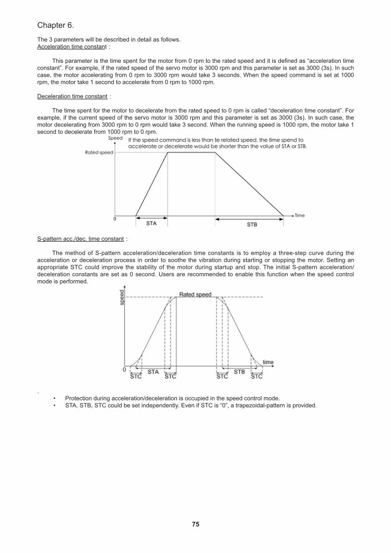
75
Chapter 6.
The 3 parameters will be described in detail as follows.Acceleration time constant:
This parameter is the time spent for the motor from 0 rpm to the rated speed and it is defined as “acceleration time constant”. For example, if the rated speed of the servo motor is 3000 rpm and this parameter is set as 3000 (3s). In such case, the motor accelerating from 0 rpm to 3000 rpm would take 3 seconds. When the speed command is set at 1000 rpm, the motor take 1 second to accelerate from 0 rpm to 1000 rpm.
Deceleration time constant:
The time spent for the motor to decelerate from the rated speed to 0 rpm is called “deceleration time constant”. For example, if the current speed of the servo motor is 3000 rpm and this parameter is set as 3000 (3s). In such case, the motor decelerating from 3000 rpm to 0 rpm would take 3 second. When the running speed is 1000 rpm, the motor take 1 second to decelerate from 1000 rpm to 0 rpm.
S-pattern acc./dec. time constant:
The method of S-pattern acceleration/deceleration time constants is to employ a three-step curve during the acceleration or deceleration process in order to soothe the vibration during starting or stopping the motor. Setting an appropriate STC could improve the stability of the motor during startup and stop. The initial S-pattern acceleration/deceleration constants are set as 0 second. Users are recommended to enable this function when the speed control mode is performed.
.• Protection during acceleration/deceleration is occupied in the speed control mode.• STA, STB, STC could be set independently. Even if STC is “0”, a trapezoidal-pattern is provided.
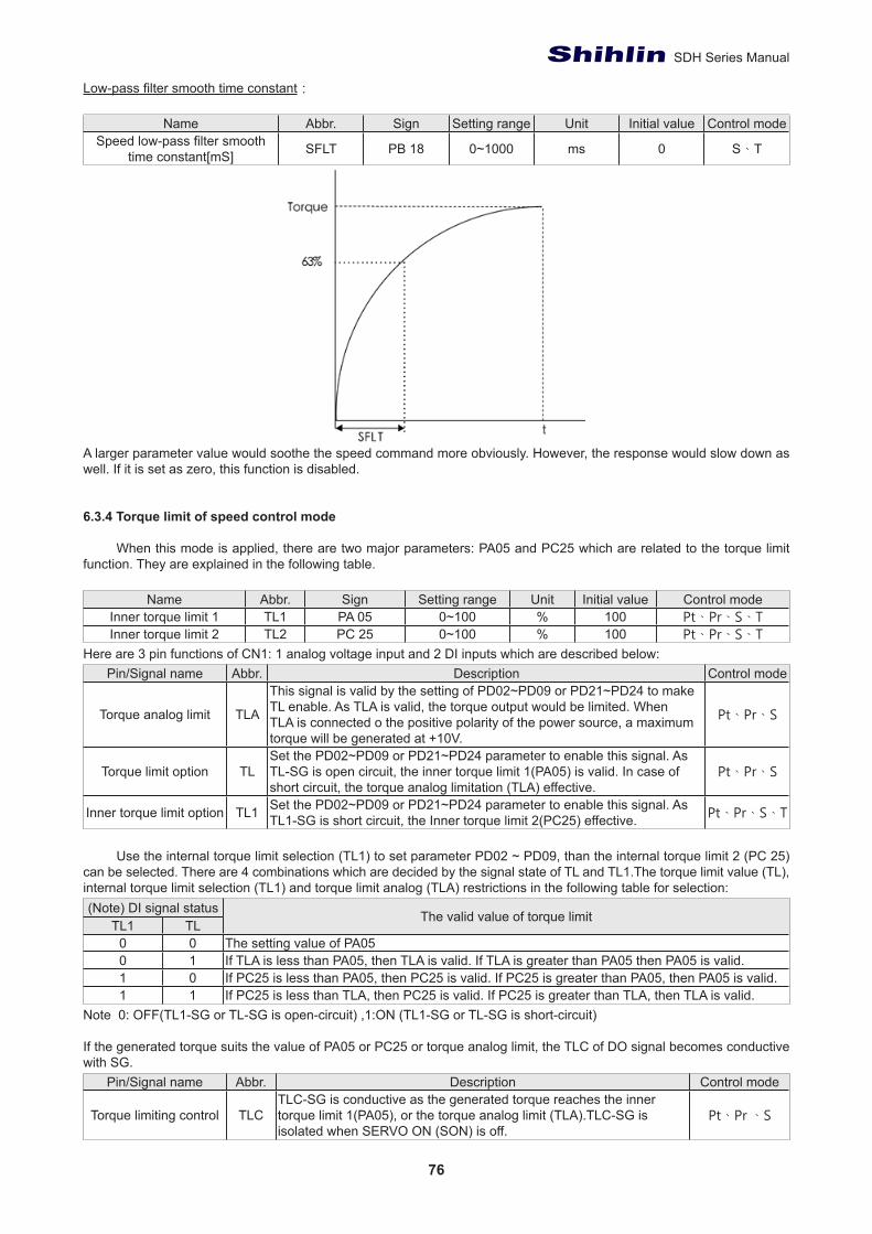
76
SDH Series Manual
Low-pass filter smooth time constant:
Name Abbr. Sign Setting range Unit Initial value Control modeSpeed low-pass filter smooth
time constant[mS] SFLT PB 18 0~1000 ms 0 S、T
A larger parameter value would soothe the speed command more obviously. However, the response would slow down as well. If it is set as zero, this function is disabled.
6.3.4 Torque limit of speed control mode
When this mode is applied, there are two major parameters: PA05 and PC25 which are related to the torque limit function. They are explained in the following table.
Name Abbr. Sign Setting range Unit Initial value Control modeInner torque limit 1 TL1 PA 05 0~100 % 100 Pt、Pr、S、TInner torque limit 2 TL2 PC 25 0~100 % 100 Pt、Pr、S、T
Here are 3 pin functions of CN1: 1 analog voltage input and 2 DI inputs which are described below:Pin/Signal name Abbr. Description Control mode
Torque analog limit TLA
This signal is valid by the setting of PD02~PD09 or PD21~PD24 to make TL enable. As TLA is valid, the torque output would be limited. When TLA is connected o the positive polarity of the power source, a maximum torque will be generated at +10V.
Pt、Pr、S
Torque limit option TLSet the PD02~PD09 or PD21~PD24 parameter to enable this signal. As TL-SG is open circuit, the inner torque limit 1(PA05) is valid. In case of short circuit, the torque analog limitation (TLA) effective.
Pt、Pr、S
Inner torque limit option TL1 Set the PD02~PD09 or PD21~PD24 parameter to enable this signal. As TL1-SG is short circuit, the Inner torque limit 2(PC25) effective. Pt、Pr、S、T
Use the internal torque limit selection (TL1) to set parameter PD02 ~ PD09, than the internal torque limit 2 (PC 25) can be selected. There are 4 combinations which are decided by the signal state of TL and TL1.The torque limit value (TL), internal torque limit selection (TL1) and torque limit analog (TLA) restrictions in the following table for selection:(Note) DI signal status The valid value of torque limit
TL1 TL0 0 The setting value of PA050 1 If TLA is less than PA05, then TLA is valid. If TLA is greater than PA05 then PA05 is valid.1 0 If PC25 is less than PA05, then PC25 is valid. If PC25 is greater than PA05, then PA05 is valid.1 1 If PC25 is less than TLA, then PC25 is valid. If PC25 is greater than TLA, then TLA is valid.
Note 0: OFF(TL1-SG or TL-SG is open-circuit) ,1:ON (TL1-SG or TL-SG is short-circuit) If the generated torque suits the value of PA05 or PC25 or torque analog limit, the TLC of DO signal becomes conductive with SG.
Pin/Signal name Abbr. Description Control mode
Torque limiting control TLCTLC-SG is conductive as the generated torque reaches the inner torque limit 1(PA05), or the torque analog limit (TLA).TLC-SG is isolated when SERVO ON (SON) is off.
Pt、Pr 、S
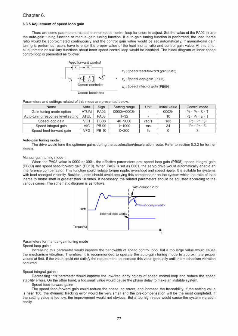
77
Chapter 6.
6.3.5 Adjustment of speed loop gain
There are some parameters related to inner speed control loop for users to adjust. Set the value of the PA02 to use the auto-gain tuning function or manual-gain tuning function. If auto-gain tuning function is performed, the load inertia ratio would be approximated continuously and the control gain value would be set automatically. If manual-gain gain tuning is performed, users have to enter the proper value of the load inertia ratio and control gain value. At this time, all automatic or auxiliary functions about inner speed control loop would be disabled. The block diagram of inner speed control loop is presented as follows:
Parameters and settings related of this mode are presented below.
Name Abbr. Sign Setting range Unit Initial value Control modeGain tuning mode option ATUM PA02 0000h~0003h - 0002h Pt、Pr、S、T
Auto-tuning response level setting ATUL PA03 1~32 - 10 Pt、Pr、S、TSpeed loop gain VG1 PB08 40~9000 rad/s 183 Pt、Pr、S
Speed integral gain VIC PB 09 1~1000 ms 34 Pt、Pr、SSpeed feed-forward gain VFG PB 10 0~200 % 0 S
Auto-gain tuning mode:The drive would tune the optimum gains during the acceleration/deceleration route. Refer to section 5.3.2 for further
details.
Manual-gain tuning mode: When the PA02 value is 0000 or 0001, the effective parameters are: speed loop gain (PB08), speed integral gain
(PB09) and speed feed-forward gain (PB10). When PA02 is set as 0001, the servo drive would automatically enable an interference compensator. This function could reduce torque ripple, overshoot and speed ripple. It is suitable for systems with load changed violently. Besides, users should avoid applying this compensator on the system which the ratio of load inertia to motor shaft is greater than 10 times. If necessary, the related parameters should be adjusted according to the various cases. The schematic diagram is as follows.
Parameters for manual-gain tuning modeSpeed loop gain:
Increasing this parameter would improve the bandwidth of speed control loop, but a too large value would cause the mechanism vibration. Therefore, it is recommended to operate the auto-gain tuning mode to approximate proper values at first. If the value could not satisfy the requirement, to increase this value gradually until the mechanism vibration occurred.
Speed integral gainn:Decreasing this parameter would improve the low-frequency rigidity of speed control loop and reduce the speed
stability errors. On the other hand, a too small value would cause the phase delay to make an instable system.Speed feed-forward gainn:The speed feed-forward gain could reduce the phase lag errors, and increase the traceability. If the setting value
is near 100, the dynamic tracking error would be very small and the pre-compensation will be the most completed. If the setting value is too low, the improvement would not obvious. But a too high value would cause the system vibration easily.

78
SDH Series Manual
6.3.6 Resonance suppression filter
(1)Auto high frequency resonance suppression function:When the mechanism with low rigidity generates resonance by reason of the large bandwidth or the large rigidity
setting value of the servo drive. If the mechanism factors could not be adjusted, Shihlin servo drive provides 3 resonance filter frequencies and 1 resonance suppression low-pass filter for users to make adjustment. Some parameters related to resonance suppression filter are introduced below.
Name Abbr. Sign Setting range Unit Initial value Control modeAuto resonance suppression mode ANCF PB27 0~2 - 1 Pt、Pr、S、TAuto resonance detection level ANCL PB28 1~300 % 50 Pt、Pr、S、TMachine resonance suppression filter (1) NHF1 PB01 50~4000 Hz 1000 Pt、Pr、S、TMachine resonance suppression attenuation (1) NHD1 PB02 0~32 dB 0 Pt、Pr、S、TMachine resonance suppression filter (2) NHF2 PB21 10~4000 Hz 1000 Pt、Pr、S、TMachine resonance suppression attenuation (2) NHD2 PB22 0~32 dB 0 Pt、Pr、S、TMachine resonance suppression filter (3) NHF3 PB25 10~4000 Hz 1000 Pt、Pr、S、TMachine resonance suppression attenuation (3) NHD3 PB26 0~32 dB 0 Pt、Pr、S、TResonance suppression low-pass filter NLP PB03 0~10000 0.1ms 10 Pt、Pr、S、T
►Manual suppression method:There are three sets of auto resonance suppression filter provided by SDH drive which one is PB01 and PB02, the
second one is PB21 and PB22 and the third one is PB25 and PB26; And there are also one set of low pass auto reso-nance suppression filter which is PB03. PB01、PB21、PB25 are suppression frequencies; PB02、PB22、PB26 are suppression attenuation rates and PB03 is time constant.
If resonance frequency of machine is known, users can set the frequency of filter and increase the attenuation rate step by step in order to have no resonance (Note 2) or slowly increasing low-pass filter time constant (reduce bandwidth of the low-pass filter) to have no resonance, but this will reduce the bandwidth of the system.
►Auto suppression method:There are two sets of auto resonance suppression filter provided by SDH drive which one is PB01 and PB02, the
second one is PB21 and PB22; PB01、PB21 are suppression frequencies; PB02、PB22 are suppression attenuation rates.
When resonance occurs, users who do not know resonance frequency can set PB27 to be 1 or 2 to operate the auto resonance suppression. The drive will detect resonant frequency and attenuation rate automatically, and then set detected result in the first filter and the second filter (Note 1).
If PB27 is set to 1, PB27 will automatically set back to 0 after finishing detecting; if PB27 is set to 2, it will continue to detect the resonance and suppression. Please refer to the following table for the parameter flow of PB27.
When PB27 is set to 1 or 2 and the resonance still persists, please check if the value of PB02 or PB22 is 32, if one of it is 32 that mean this resonance could not be suppressed by filter efficiency. Please reduce system bandwidth and estimate again in such case. If the value is less than 32 and bigger than 0 means the resonant frequency have been detected in auto detection mode but probably the attenuation is not enough to let have no resonance (Note 1). Users can increase attenuation rate (Note 2) in such case. If the PB02 or PB22 is 0 means there is no resonance frequency be detected, it is possible from the detecting level (PB28) is too high. It is recommended to reduce the detecting level and set PB27 to be 1 or 2 to detect again. Please see the chart below for auto resonance suppression flow.
Note 1. Drive will detect the most suitable not the best attenuation rate to ensure stability of the systemNote 2. Note that when adjust the attenuation rate manually, the setting value is too large may cause system instability.
PB27 Parameter flowchartPB27 Current value PB27 Desired value Function
0 1 Clear the setting value of PB01~02, 21~22 and enable auto resonance suppression function.
0 2 Clear the setting value of PB01~02, 21~22 and enable auto resonance suppression function continuously.
1 0 Save the setting value of PB01~02, 21~22 and disable auto resonance suppression function.
1 1 Clear the setting value of PB01~02, 21~22 and enable auto resonance suppression function.
1 2 Do not clear the setting value of PB01~02, 21~22 and enable auto resonance suppression function continuously.
2 0 Save the setting value of PB01~02, 21~22 and disable auto resonance suppression function.
2 1 Clear the setting value of PB01~02, 21~22 and enable auto resonance suppression function.
2 2 Do not clear the setting value of PB01~02, 21~22 and enable auto resonance suppression function continuously.

79
Chapter 6.
(2)Auto low frequency resonance suppression function:
When the command changes instantly due to lack of rigidity makes the transmission side and the load side of the motor cannot be synchronized will cause mechanical vibration, influence position accurate and defect-free rate for product. This phenomenon would usually be improved by reducing bandwidth of system, but it will lose the response. In order to do resonance suppression without reducing the bandwidth, the SDH servo drive provides the method of "Auto low frequency resonance suppression function" which parameters, setting range and the initial values are shown in the following table.
And provides two low-frequency filter, users can operate manual or auto resonance suppression according to their needs.
Name Abbr. Sign Setting range Unit Initial value Control modeAuto low frequency resonance suppression mode AVSM PB29 0~1 - 0 Pt、Pr
Low frequency resonance detection level VCL PB30 1~8000 pulse 50 Pt、PrLow frequency resonance suppression frequency (1) VSF1 PB31 1~3000 0.1Hz 100 Pt、Pr
Low frequency resonance suppression gain (1) VSG1 PB32 0~15 - 0 Pt、PrLow frequency resonance suppression frequency (2) VSF2 PB33 1~3000 0.1Hz 100 Pt、Pr
Low frequency resonance suppression gain(2) VSG2 PB34 0~15 - 0 Pt、Pr
►Manual suppression method:There are two sets of auto resonance suppression filter for users to set manually which one is PB31 and PB32, the
second one is PB33 and PB34; PB31、PB33 are suppression frequencies; PB32、PB34 are suppression gain.If resonance frequency of machine is known, users can set the frequency of filter at PB31、PB33 and set PB32、
PB34 to ‘1’ where ‘1’ means start to open suppression function and ‘0’ means close suppression function.Increase the gain value to enhance the response. (Note 1)Increase the attenuation rate step by step in order to have no resonance (Note 2) or slowly increasing low-pass
filter time constant (reduce bandwidth of the low-pass filter) to have no resonance, but this will reduce the bandwidth of the system.
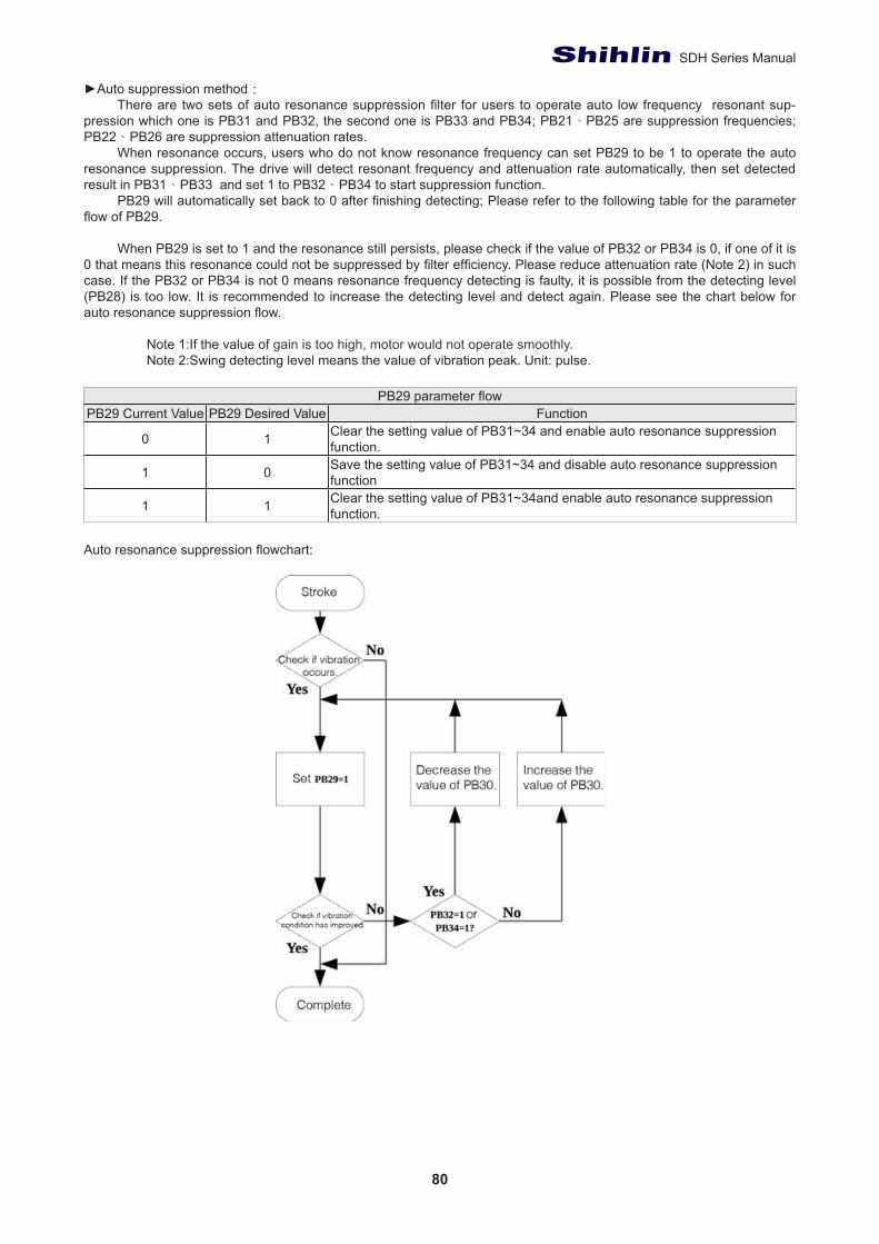
80
SDH Series Manual
►Auto suppression method:There are two sets of auto resonance suppression filter for users to operate auto low frequency resonant sup-
pression which one is PB31 and PB32, the second one is PB33 and PB34; PB21、PB25 are suppression frequencies; PB22、PB26 are suppression attenuation rates.
When resonance occurs, users who do not know resonance frequency can set PB29 to be 1 to operate the auto resonance suppression. The drive will detect resonant frequency and attenuation rate automatically, then set detected result in PB31、PB33 and set 1 to PB32、PB34 to start suppression function.
PB29 will automatically set back to 0 after finishing detecting; Please refer to the following table for the parameter flow of PB29.
When PB29 is set to 1 and the resonance still persists, please check if the value of PB32 or PB34 is 0, if one of it is 0 that means this resonance could not be suppressed by filter efficiency. Please reduce attenuation rate (Note 2) in such case. If the PB32 or PB34 is not 0 means resonance frequency detecting is faulty, it is possible from the detecting level (PB28) is too low. It is recommended to increase the detecting level and detect again. Please see the chart below for auto resonance suppression flow.
Note 1:If the value of gain is too high, motor would not operate smoothly.Note 2:Swing detecting level means the value of vibration peak. Unit: pulse.
PB29 parameter flow PB29 Current Value PB29 Desired Value Function
0 1 Clear the setting value of PB31~34 and enable auto resonance suppression function.
1 0 Save the setting value of PB31~34 and disable auto resonance suppression function
1 1 Clear the setting value of PB31~34and enable auto resonance suppression function.
Auto resonance suppression flowchart:
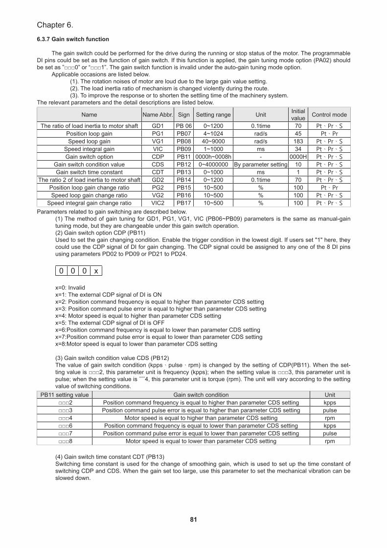
81
Chapter 6.
6.3.7 Gain switch function
The gain switch could be performed for the drive during the running or stop status of the motor. The programmable DI pins could be set as the function of gain switch. If this function is applied, the gain tuning mode option (PA02) should be set as ”□□□0” or “□□□1”. The gain switch function is invalid under the auto-gain tuning mode option.
Applicable occasions are listed below.(1). The rotation noises of motor are loud due to the large gain value setting.(2). The load inertia ratio of mechanism is changed violently during the route.(3). To improve the response or to shorten the settling time of the machinery system.
The relevant parameters and the detail descriptions are listed below.
Name Name Abbr. Sign Setting range Unit Initial value Control mode
The ratio of load inertia to motor shaft GD1 PB 06 0~1200 0.1time 70 Pt、Pr、SPosition loop gain PG1 PB07 4~1024 rad/s 45 Pt、PrSpeed loop gain VG1 PB08 40~9000 rad/s 183 Pt、Pr、S
Speed integral gain VIC PB09 1~1000 ms 34 Pt、Pr、SGain switch option CDP PB11 0000h~0008h - 0000H Pt、Pr、S
Gain switch condition value CDS PB12 0~4000000 By parameter setting 10 Pt、Pr、SGain switch time constant CDT PB13 0~1000 ms 1 Pt、Pr、S
The ratio 2 of load inertia to motor shaft GD2 PB14 0~1200 0.1time 70 Pt、Pr、SPosition loop gain change ratio PG2 PB15 10~500 % 100 Pt、PrSpeed loop gain change ratio VG2 PB16 10~500 % 100 Pt、Pr、S
Speed integral gain change ratio VIC2 PB17 10~500 % 100 Pt、Pr、SParameters related to gain switching are described below.
(1) The method of gain tuning for GD1, PG1, VG1, VIC (PB06~PB09) parameters is the same as manual-gain tuning mode, but they are changeable under this gain switch operation.(2) Gain switch option CDP (PB11)Used to set the gain changing condition. Enable the trigger condition in the lowest digit. If users set "1" here, they could use the CDP signal of DI for gain changing. The CDP signal could be assigned to any one of the 8 DI pins using parameters PD02 to PD09 or PD21 to PD24.
0 0 0 x x=0: Invalidx=1: The external CDP signal of DI is ONx=2: Position command frequency is equal to higher than parameter CDS settingx=3: Position command pulse error is equal to higher than parameter CDS settingx=4: Motor speed is equal to higher than parameter CDS settingx=5: The external CDP signal of DI is OFFx=6:Position command frequency is equal to lower than parameter CDS settingx=7:Position command pulse error is equal to lower than parameter CDS settingx=8:Motor speed is equal to lower than parameter CDS setting
(3) Gain switch condition value CDS (PB12)The value of gain switch condition (kpps、pulse、rpm) is changed by the setting of CDP(PB11). When the set-ting value is □□□2, this parameter unit is frequency (kpps); when the setting value is □□□3, this parameter unit is pulse; when the setting value is ¨¨¨4, this parameter unit is torque (rpm). The unit will vary according to the setting value of switching conditions.
PB11 setting value Gain switch condition Unit □□□2 Position command frequency is equal to higher than parameter CDS setting kpps □□□3 Position command pulse error is equal to higher than parameter CDS setting pulse □□□4 Motor speed is equal to higher than parameter CDS setting rpm □□□6 Position command frequency is equal to lower than parameter CDS setting kpps □□□7 Position command pulse error is equal to lower than parameter CDS setting pulse □□□8 Motor speed is equal to lower than parameter CDS setting rpm
(4) Gain switch time constant CDT (PB13)Switching time constant is used for the change of smoothing gain, which is used to set up the time constant of switching CDP and CDS. When the gain set too large, use this parameter to set the mechanical vibration can be slowed down.

82
SDH Series Manual
(5) The ratio 2 of load inertia to motor shaft GD2 (PB14)Enable to set to change the ratio of load inertia to motor shaft and if the ratio of load inertia to motor shaft does not change, please set this parameter to the value of GD1 (PB06).
(6) The change rate PG2、VG2、VIC2 (PB15~PB17) when position gain 2、speed gain 2、speed integral gain switch.The original servo gain value would correct to the ratios (%) set by PG2, VG2, and VIC to run gain switching.
Example 1: The external DI signal as the switch option.
Relevant parameters setting:Name Name Abbr. Sign Setting value Unit
The ratio of load inertia to motor shaft GD1 PB06 70 0.1timePosition loop gain PG1 PB07 100 rad/sSpeed loop gain VG1 PB08 500 rad/s
Speed integral gain VIC PB09 100 msGain switch option CDP PB11 0001 -
Gain switch time constant CDT PB13 10 msThe ratio 2 of load inertia to motor shaft GD2 PB14 20 0.1time
Position loop gain change ratio PG2 PB15 80 %Speed loop gain change ratio VG2 PB16 120 %
Speed integral gain change ratio VIC2 PB17 150 %
The sequence of gain switch:
The states of parameters change:Name CDP OFF CDP ON CDP OFF
The ratio of load inertia to motor shaft 10 → 20 → 10Position loop gain 100 → 80 → 100Speed loop gain 500 → 600 → 500
Speed integral gain 100 → 150 → 100
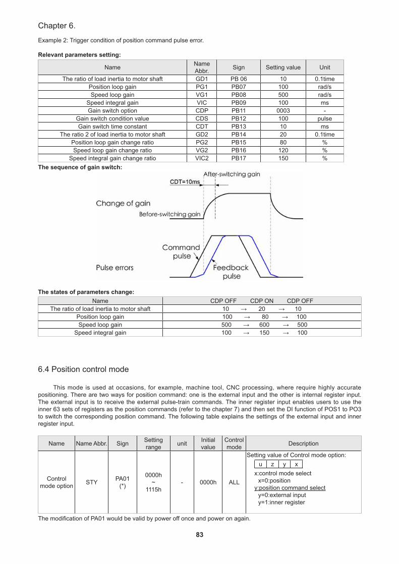
83
Chapter 6.
Example 2: Trigger condition of position command pulse error.
Relevant parameters setting:
Name Name Abbr. Sign Setting value Unit
The ratio of load inertia to motor shaft GD1 PB 06 10 0.1timePosition loop gain PG1 PB07 100 rad/sSpeed loop gain VG1 PB08 500 rad/s
Speed integral gain VIC PB09 100 msGain switch option CDP PB11 0003 -
Gain switch condition value CDS PB12 100 pulseGain switch time constant CDT PB13 10 ms
The ratio 2 of load inertia to motor shaft GD2 PB14 20 0.1timePosition loop gain change ratio PG2 PB15 80 %Speed loop gain change ratio VG2 PB16 120 %
Speed integral gain change ratio VIC2 PB17 150 %The sequence of gain switch:
The states of parameters change:Name CDP OFF CDP ON CDP OFF
The ratio of load inertia to motor shaft 10 → 20 → 10Position loop gain 100 → 80 → 100Speed loop gain 500 → 600 → 500
Speed integral gain 100 → 150 → 100
6.4 Position control mode
This mode is used at occasions, for example, machine tool, CNC processing, where require highly accurate positioning. There are two ways for position command: one is the external input and the other is internal register input. The external input is to receive the external pulse-train commands. The inner register input enables users to use the inner 63 sets of registers as the position commands (refer to the chapter 7) and then set the DI function of POS1 to PO3 to switch the corresponding position command. The following table explains the settings of the external input and inner register input.
Name Name Abbr. Sign Setting range unit Initial
valueControl mode Description
Control mode option STY PA01
(*)
0000h~
1115h- 0000h ALL
Setting value of Control mode option:u z y x
x:control mode selectx=0:position
y:position command selecty=0:external inputy=1:inner register
The modification of PA01 would be valid by power off once and power on again.
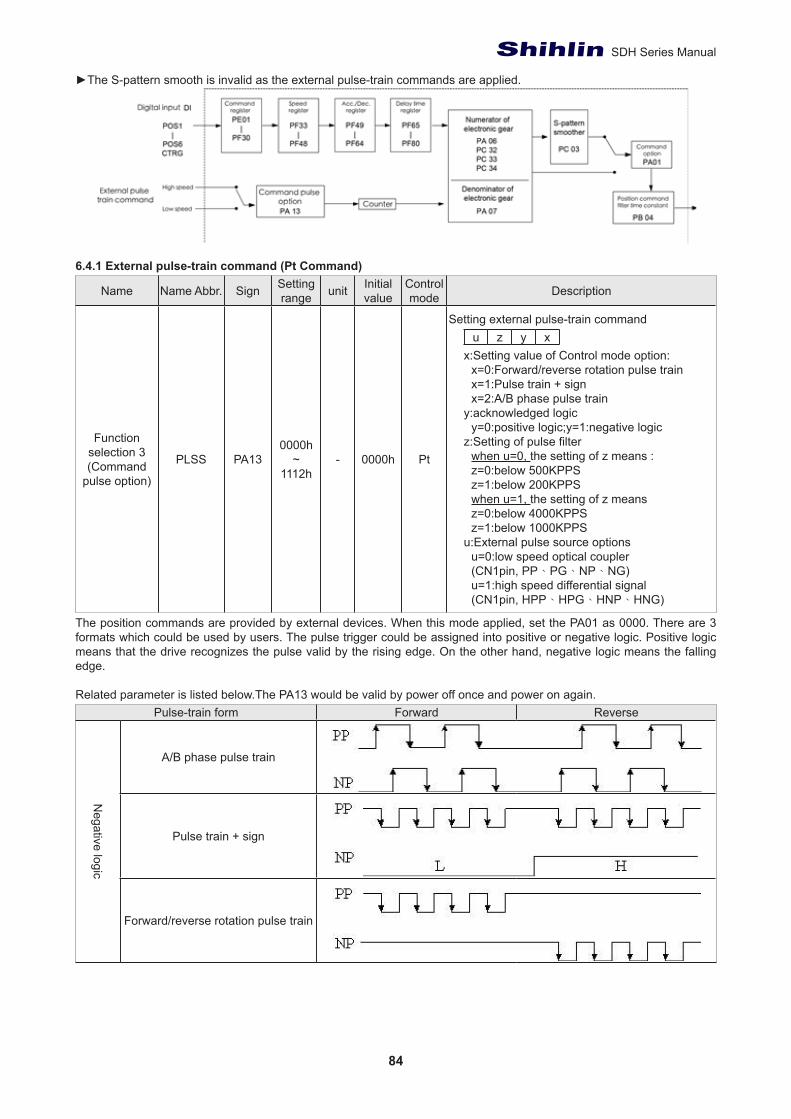
84
SDH Series Manual
►The S-pattern smooth is invalid as the external pulse-train commands are applied.
6.4.1 External pulse-train command (Pt Command)
Name Name Abbr. Sign Setting range unit Initial
valueControl mode Description
Function selection 3(Command
pulse option)
PLSS PA130000h
~1112h
- 0000h Pt
Setting external pulse-train commandu z y x
x:Setting value of Control mode option:x=0:Forward/reverse rotation pulse train x=1:Pulse train + signx=2:A/B phase pulse train
y:acknowledged logicy=0:positive logic;y=1:negative logic
z:Setting of pulse filterwhen u=0, the setting of z means :z=0:below 500KPPSz=1:below 200KPPSwhen u=1, the setting of z means z=0:below 4000KPPSz=1:below 1000KPPS
u:External pulse source optionsu=0:low speed optical coupler(CN1pin, PP、PG、NP、NG)u=1:high speed differential signal(CN1pin, HPP、HPG、HNP、HNG)
The position commands are provided by external devices. When this mode applied, set the PA01 as 0000. There are 3 formats which could be used by users. The pulse trigger could be assigned into positive or negative logic. Positive logic means that the drive recognizes the pulse valid by the rising edge. On the other hand, negative logic means the falling edge.
Related parameter is listed below.The PA13 would be valid by power off once and power on again.Pulse-train form Forward Reverse
Negative logic
A/B phase pulse train
Pulse train + sign
Forward/reverse rotation pulse train
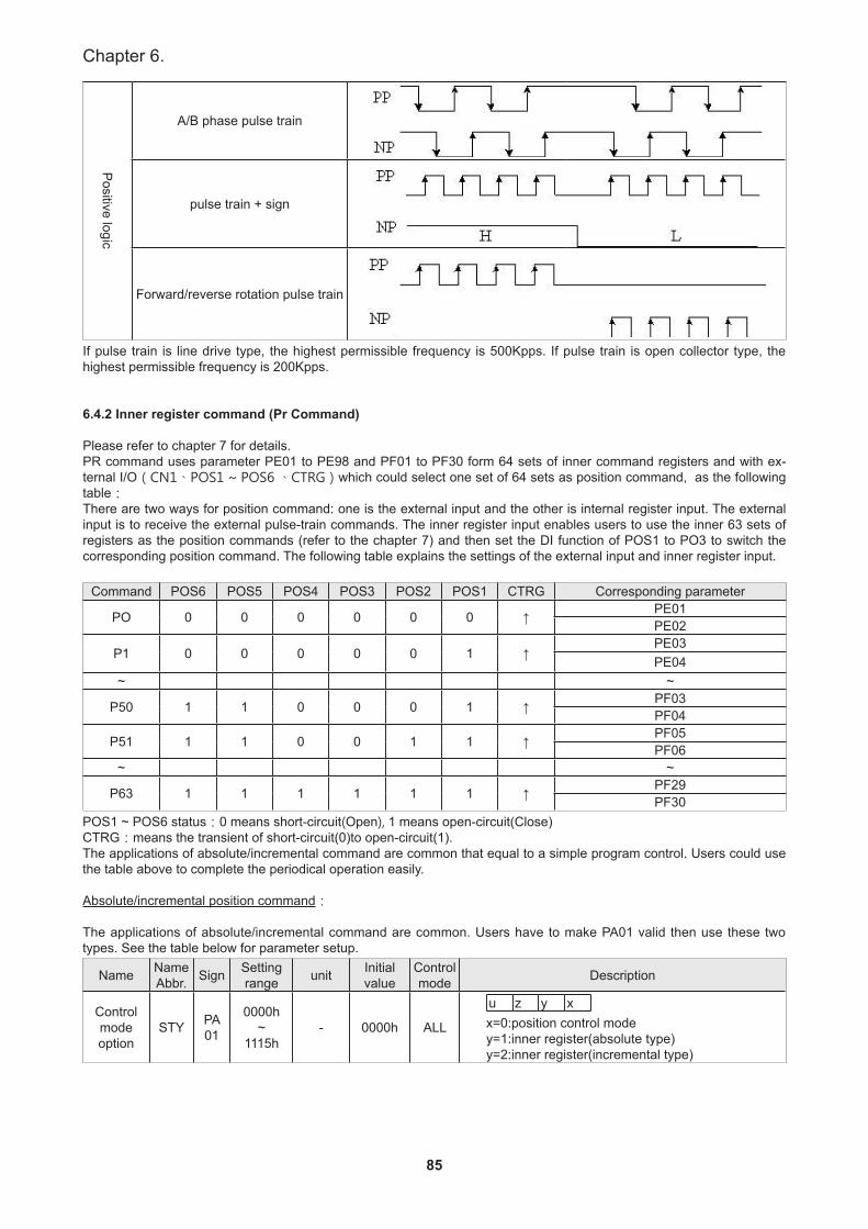
85
Chapter 6.
Positive logic
A/B phase pulse train
pulse train + sign
Forward/reverse rotation pulse train
If pulse train is line drive type, the highest permissible frequency is 500Kpps. If pulse train is open collector type, the highest permissible frequency is 200Kpps.
6.4.2 Inner register command (Pr Command)
Please refer to chapter 7 for details. PR command uses parameter PE01 to PE98 and PF01 to PF30 form 64 sets of inner command registers and with ex-ternal I/O(CN1、POS1 ~ POS6 、CTRG)which could select one set of 64 sets as position command, as the following table:There are two ways for position command: one is the external input and the other is internal register input. The external input is to receive the external pulse-train commands. The inner register input enables users to use the inner 63 sets of registers as the position commands (refer to the chapter 7) and then set the DI function of POS1 to PO3 to switch the corresponding position command. The following table explains the settings of the external input and inner register input.
Command POS6 POS5 POS4 POS3 POS2 POS1 CTRG Corresponding parameter
PO 0 0 0 0 0 0 ↑ PE01PE02
P1 0 0 0 0 0 1 ↑PE03PE04
~ ~
P50 1 1 0 0 0 1 ↑ PF03PF04
P51 1 1 0 0 1 1 ↑ PF05PF06
~ ~
P63 1 1 1 1 1 1 ↑ PF29PF30
POS1 ~ POS6 status:0 means short-circuit(Open), 1 means open-circuit(Close)CTRG:means the transient of short-circuit(0)to open-circuit(1).The applications of absolute/incremental command are common that equal to a simple program control. Users could use the table above to complete the periodical operation easily.
Absolute/incremental position command:
The applications of absolute/incremental command are common. Users have to make PA01 valid then use these two types. See the table below for parameter setup.
Name Name Abbr. Sign Setting
range unit Initial value
Control mode Description
Control mode option
STY PA 01
0000h~
1115h- 0000h ALL
u z y xx=0:position control mode y=1:inner register(absolute type)y=2:inner register(incremental type)
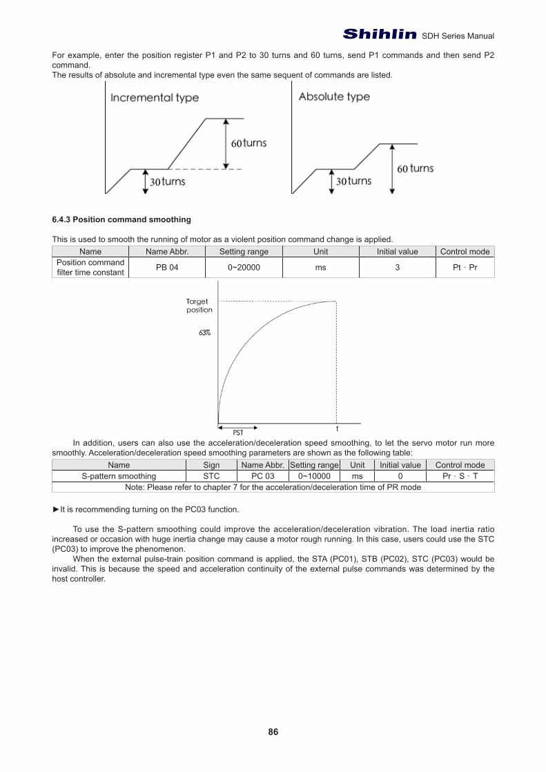
86
SDH Series Manual
For example, enter the position register P1 and P2 to 30 turns and 60 turns, send P1 commands and then send P2 command.The results of absolute and incremental type even the same sequent of commands are listed.
6.4.3 Position command smoothing
This is used to smooth the running of motor as a violent position command change is applied.Name Name Abbr. Setting range Unit Initial value Control mode
Position command filter time constant PB 04 0~20000 ms 3 Pt、Pr
In addition, users can also use the acceleration/deceleration speed smoothing, to let the servo motor run more smoothly. Acceleration/deceleration speed smoothing parameters are shown as the following table:
Name Sign Name Abbr. Setting range Unit Initial value Control modeS-pattern smoothing STC PC 03 0~10000 ms 0 Pr、S、T
Note: Please refer to chapter 7 for the acceleration/deceleration time of PR mode
►It is recommending turning on the PC03 function.
To use the S-pattern smoothing could improve the acceleration/deceleration vibration. The load inertia ratio increased or occasion with huge inertia change may cause a motor rough running. In this case, users could use the STC (PC03) to improve the phenomenon.
When the external pulse-train position command is applied, the STA (PC01), STB (PC02), STC (PC03) would be invalid. This is because the speed and acceleration continuity of the external pulse commands was determined by the host controller.
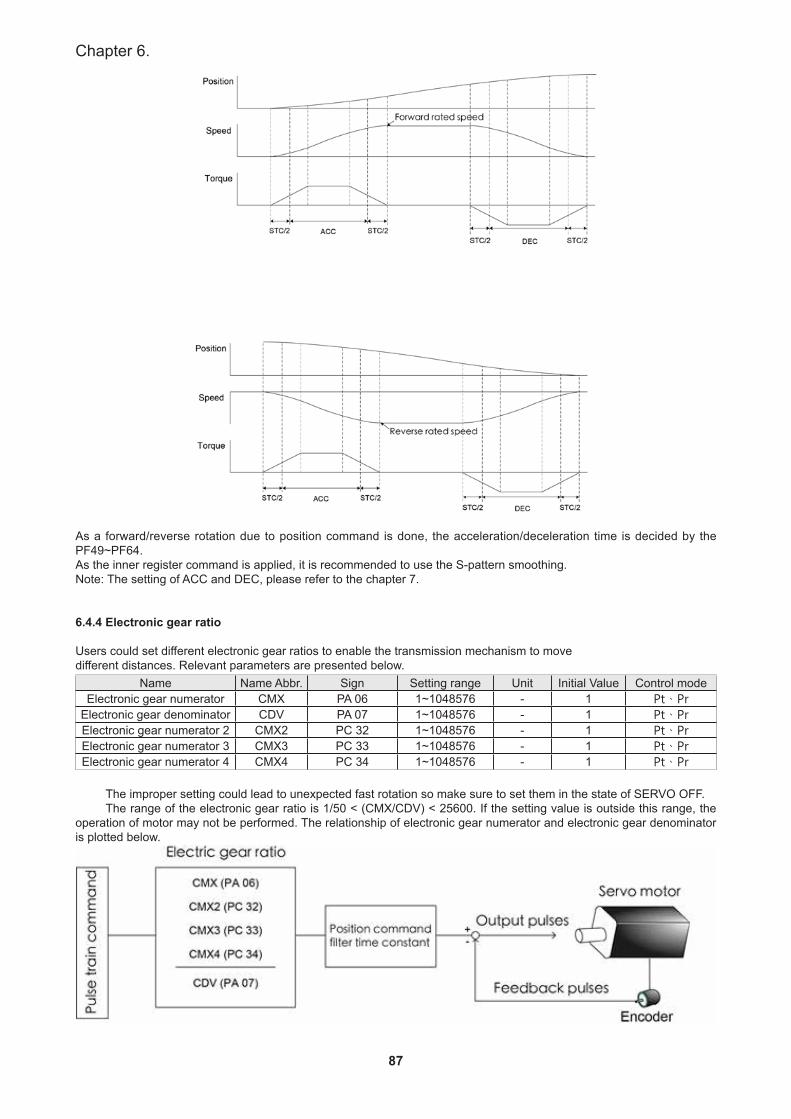
87
Chapter 6.
As a forward/reverse rotation due to position command is done, the acceleration/deceleration time is decided by the PF49~PF64. As the inner register command is applied, it is recommended to use the S-pattern smoothing.Note: The setting of ACC and DEC, please refer to the chapter 7.
6.4.4 Electronic gear ratio
Users could set different electronic gear ratios to enable the transmission mechanism to movedifferent distances. Relevant parameters are presented below.
Name Name Abbr. Sign Setting range Unit Initial Value Control modeElectronic gear numerator CMX PA 06 1~1048576 - 1 Pt、Pr
Electronic gear denominator CDV PA 07 1~1048576 - 1 Pt、PrElectronic gear numerator 2 CMX2 PC 32 1~1048576 - 1 Pt、PrElectronic gear numerator 3 CMX3 PC 33 1~1048576 - 1 Pt、PrElectronic gear numerator 4 CMX4 PC 34 1~1048576 - 1 Pt、Pr
The improper setting could lead to unexpected fast rotation so make sure to set them in the state of SERVO OFF.The range of the electronic gear ratio is 1/50 < (CMX/CDV) < 25600. If the setting value is outside this range, the
operation of motor may not be performed. The relationship of electronic gear numerator and electronic gear denominator is plotted below.
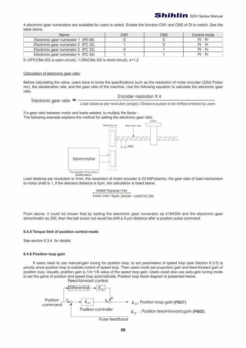
88
SDH Series Manual
4 electronic gear numerators are available for users to select. Enable the function CM1 and CM2 of DI to switch. See the table below.
Name CM1 CM2 Control modeElectronic gear numerator 1 (PA 06) 0 0 Pt、PrElectronic gear numerator 2 (PC 32) 1 0 Pt、PrElectronic gear numerator 3 (PC 33) 0 1 Pt、PrElectronic gear numerator 4 (PC 34) 1 1 Pt、Pr
0: OFF(CMx-SG is open-circuit), 1:ON(CMx-SG is short-circuit), x=1,2
Calculation of electronic gear ratio:
Before calculating the value, users have to know the specifications such as the resolution of motor encoder (22bit Pulse/rev), the deceleration rate, and the gear ratio of the machine. Use the following equation to calculate the electronic gear ratio.
If a gear ratio between motor and loads existed, to multiply the factor : The following example explains the method for setting the electronic gear ratio.
Load distance per revolution is 1mm, the resolution of motor encoder is 22-bitPulse/rev, the gear ratio of load mechanism to motor shaft is 1, if the demand distance is 5μm, the calculation is listed below.
=1048576/200
From above, it could be known that by setting the electronic gear numerator as 4194304 and the electronic gear denominator as 200, then the ball screw rod would be shift a 5-μm distance after a position pulse command.
6.4.5 Torque limit of position control mode See section 6.3.4. for details.
6.4.6 Position loop gain
If users need to use manual-gain tuning for position loop, to set parameters of speed loop (see Section 6.3.5) is priority since position loop is outside control of speed loop. Then users could set proportion gain and feed-forward gain of position loop. Usually, position gain is 1/4~1/6 value of the speed loop gain. Users could also use auto-gain tuning mode to set the gains of position and speed loop automatically. Position loop block diagram is presented below.
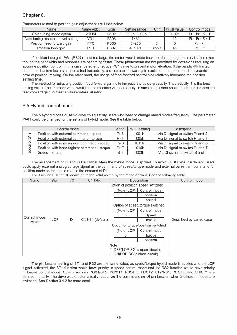
89
Chapter 6.
Parameters related to position gain adjustment are listed below.Name Name Abbr. Sign Setting range Unit Initial value Control mode
Gain tuning mode option ATUM PA02 0000h~0003h - 0002h Pt、Pr、S、TAuto-tuning response level setting ATUL PA03 1~32 - 10 Pt、Pr、S、T
Position feed-forward gain FFC PB05 0~200 % 0 Pt、PrPosition loop gain PG1 PB07 4~1024 rad/s 45 Pt、Pr
If position loop gain PG1 (PB07) is set too large, the motor would rotate back and forth and generate vibration even though the bandwidth and response are becoming faster. These phenomena are not permitted for occasions requiring an accurate position control. In this case, be sure to reduce PG1 value to prevent motor vibration. If the bandwidth limited due to mechanism factors causes a bad traceability, position feed-forward gain could be used to reduce the dynamic error of position tracking. On the other hand, the usage of feed-forward control also relatively increases the position settling time.
The method for adjusting position feed-forward gain is to increase the value gradually. Theoretically, 1 is the best setting value. The improper value would cause machine vibration easily. In such case, users should decrease the position feed-forward gain to meet a vibration-free situation.
6.5 Hybrid control mode
The 5 hybrid modes of servo drive could satisfy users who need to change varied modes frequently. The parameter PA01 could be changed for the setting of hybrid mode. See the table below.
Control mode Abbr. PA 01 Setting Description
Hybrid m
ode
Position with external command - speed Pt-S 1001h Via DI signal to switch Pt and SPosition with external command - torque Pt-T 1005h Via DI signal to switch Pt and TPosition with inner register command - speed Pr-S 1011h Via DI signal to switch Pr and SPosition with inner register command - torque Pr-T 1015h Via DI signal to switch Pr and TSpeed - torque S-T 1003h Via DI signal to switch S and T
The arrangement of DI and DO is critical when the hybrid mode is applied. To avoid DI/DO pins insufficient, users could apply external analog voltage signal as the command of speed/torque mode and external pulse train command for position mode so that could reduce the demand of DI.
The function LOP of DI should be made valid as the hybrid mode applied. See the following table.Name Sign I/O CN1No. Description Control mode
Control mode switch LOP DI CN1-21 (default)
Option of position/speed switched(Note) LOP Control mode
0 position1 speed
Option of speed/torque switched(Note) LOP Control mode
0 Speed1 Torque
Option of torque/position switched(Note) LOP Control mode
0 Torque1 position
Note 0: OFF(LOP-SG is open-circuit), 1: ON(LOP-SG is short-circuit)
Described by varied case
The pin function setting of ST1 and RS2 are the same value, as speed/torque hybrid mode is applied and the LOP signal activated, the ST1 function would have priority in speed control mode and the RS2 function would have priority in torque control mode. Others such as POS1/SP2, PC/ST1, RS2/PC, TL/ST2, ST2/RS1, RS1/TL, and CR/SP1 are defined mutually. The drive would automatically recognize the corresponding DI pin function when 2 different modes are switched. See Section 3.4.2 for more detail.
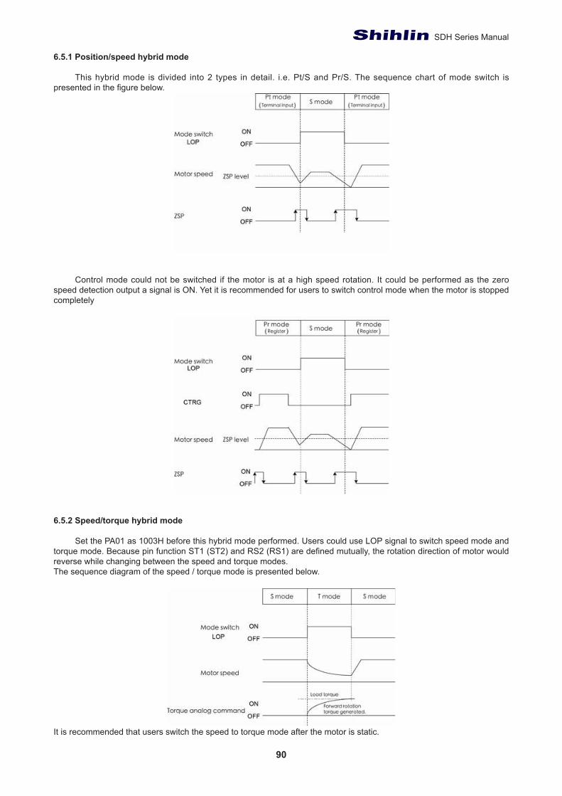
90
SDH Series Manual
6.5.1 Position/speed hybrid mode
This hybrid mode is divided into 2 types in detail. i.e. Pt/S and Pr/S. The sequence chart of mode switch is presented in the figure below.
Control mode could not be switched if the motor is at a high speed rotation. It could be performed as the zero
speed detection output a signal is ON. Yet it is recommended for users to switch control mode when the motor is stopped completely
6.5.2 Speed/torque hybrid mode
Set the PA01 as 1003H before this hybrid mode performed. Users could use LOP signal to switch speed mode and torque mode. Because pin function ST1 (ST2) and RS2 (RS1) are defined mutually, the rotation direction of motor would reverse while changing between the speed and torque modes.The sequence diagram of the speed / torque mode is presented below.
It is recommended that users switch the speed to torque mode after the motor is static.
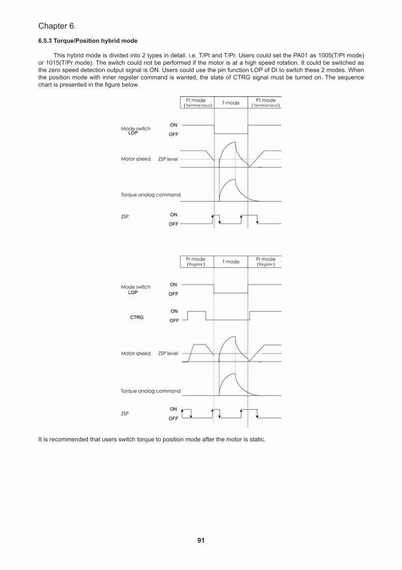
91
Chapter 6.
6.5.3 Torque/Position hybrid mode
This hybrid mode is divided into 2 types in detail. i.e. T/Pt and T/Pr. Users could set the PA01 as 1005(T/Pt mode) or 1015(T/Pr mode). The switch could not be performed if the motor is at a high speed rotation. It could be switched as the zero speed detection output signal is ON. Users could use the pin function LOP of DI to switch these 2 modes. When the position mode with inner register command is wanted, the state of CTRG signal must be turned on. The sequence chart is presented in the figure below.
It is recommended that users switch torque to position mode after the motor is static.
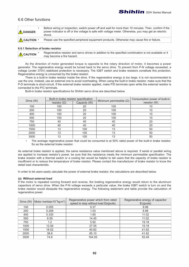
92
SDH Series Manual
6.6 Other functions
• Before wiring or inspection, switch power off and wait for more than 10 minutes. Then, confirm if the power indicator is off or the voltage is safe with voltage meter. Otherwise, you may get an electric shock.
• Please use the specified peripheral equipment products. Otherwise may cause fire or failure.
6.6.1 Selection of brake resistor• Regenerative resistor and servo drives in addition to the specified combination is not available or it
may become a fire hazard.
As the direction of motor generated torque is opposite to the rotary direction of motor, it becomes a power generator. The regenerative energy would be turned back to the servo drive. To prevent from P-N voltage exceeded, a voltage (under 370V) stabilized protection is necessary. The IGBT switch and brake resistors constitute this protection. Regenerative energy is consumed by the brake resistor.
There is a built-in brake resistor inside the drive. If the regenerative energy is too large, it is not recommended to use the one. Instead, use an external one to avoid overheating. When using the built-in brake resistor, make sure that the P-D terminals is short-circuit. If the external brake resistor applied, make P/D terminals open while the external resistor is connected to the P/C terminals.
Built-in brake resistor specifications for Shihlin servo drive are described below.
Drive (W) Built-in brake resistor specification Minimum permissible (Ω) Consumption power of built-in resistor (W)resistor (Ω) Capacity (W)
100 100 20 100 10200 100 20 100 10400 100 20 100 10500 100 20 100 10750 40 40 40 20
1000 40 40 40 201500 13 100 13 502000 13 100 13 503500 13 100 13 50
• The average regenerative power that could be consumed is at 50% rated power of the built-in brake resistor. So as the external brake resistor.
As external brake resistor is applied, the same resistance value mentioned above is required. If serial or parallel wiring are applied to increase resistor’s power, be sure that the resistance meets the minimum permissible specification. The brake resistor with a thermal switch or a cooling fan would be helpful to tell users that the capacity of brake resistor is insufficient or to reduce the temperature of brake resistor. Please contact the manufacturer of brake resistor to know the detail load characteristic.
In order to let users easily calculate the power of external brake resistor, the calculations are described below.
(a) Without external loadIf the motor is repeated running forward and reverse, the braking regenerative energy would return to the aluminum capacitors of servo drive. When the P-N voltage exceeds a particular value, the brake IGBT switch is turn on and the brake resistor would dissipate the regenerative energy. The following statement and table provide the calculation of regenerative power.
Drive (W) Motor inertia(x10-4kg‧m2) Regenerative power which from rated speed to stop without load Es(joule)
Regenerative energy of capacitor Ec(joule)
100 0.055 0.27 8.98200 0.208 1.03 8.98400 0.335 1.65 11.02500 6.59 14.45 11.02750 1.2 5.92 19.18
1000 12.56 27.55 19.181500 18.52 40.62 41.622000 38.8 85.10 41.623500 74.8 164.05 55.49
DANGER
CAUTION
CAUTION
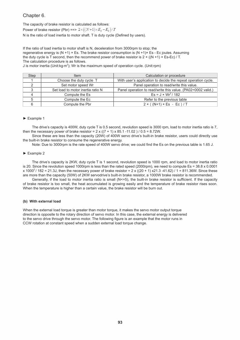
93
Chapter 6.
The capacity of brake resistor is calculated as follows:Power of brake resistor (Pbr) ==> N is the ratio of load inertia to motor shaft. T is duty cycle (Defined by users).
If the ratio of load inertia to motor shaft is N, deceleration from 3000rpm to stop; theregenerative energy is (N +1) × Es. The brake resistor consumption is (N +1)× Es - Ec joules. Assumingthe duty cycle is T second, then the recommend power of brake resistor is 2 × ((N +1) × Es-Ec) / T. The calculation procedure is as follows.J is motor inertia (Unit:kg‧m2); Wr is the maximum speed of operation cycle. (Unit:rpm)
Step Item Calculation or procedure1 Choose the duty cycle T With user’s application to decide the repeat operation cycle.2 Set motor speed Wr Panel operation to read/write this value.3 Set load to motor inertia ratio N Panel operation to read/write this value. (PA02=0002 valid.)4 Compute the Es Es = J × Wr2 / 1825 Compute the Ec Refer to the previous table6 Compute the Pbr 2 ×((N+1) × Es - Ec)/ T
► Example 1
The drive’s capacity is 400W, duty cycle T is 0.5 second, revolution speed is 3000 rpm, load to motor inertia ratio is 7, then the necessary power of brake resistor = 2 x ((7 + 1) x 85.1 -11.02 ) / 0.5 = 8.72W.
Since these are less than the capacity (20W) of 400W servo drive’s built-in brake resistor, users could directly use the built-in brake resistor to consume the regenerative energy.
Note: Due to 3000rpm is the rate speed of 400W servo drive; we could find the Es on the previous table is 1.65 J.
► Example 2
The drive’s capacity is 2KW, duty cycle T is 1 second, revolution speed is 1000 rpm, and load to motor inertia ratio is 20. Since the revolution speed 1000rpm is less than the rated speed (2000rpm), we need to compute Es = 38.8 x 0.0001 x 10002 / 182 = 21.3J, then the necessary power of brake resistor = 2 x ((20 + 1) x21.3 -41.62) / 1 = 811.36W. Since these are more than the capacity (50W) of 2KW servodrive’s built-in brake resistor, a 1000W brake resistor is recommended.
Generally, if the load to motor inertia ratio is small (N<=5), the built-in brake resistor is sufficient. If the capacity of brake resistor is too small, the heat accumulated is growing easily and the temperature of brake resistor rises soon. When the temperature is higher than a certain value, the brake resistor will be burn out.
(b) With external load
When the external load torque is greater than motor torque, it makes the servo motor output torquedirection is opposite to the rotary direction of servo motor. In this case, the external energy is deliveredto the servo drive through the servo motor. The following figure is an example that the motor runs inCCW rotation at constant speed when a sudden external load torque change.
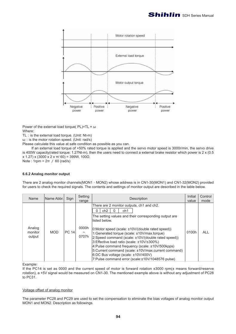
94
SDH Series Manual
Power of the external load torque( PL)=TL × ω Where: TL:is the external load torque. (Unit: Nt-m) ω:is the motor rotation speed. (Unit: rad/s) Please calculate this value at safe condition as possible as you can.
If an external load torque of +50% rated torque is applied and the servo motor speed is 3000r/min, the servo drive is 400W capacity(rated torque: 1.27Nt-m), then the users need to connect a external brake resistor which power is 2 x (0.5 x 1.27) x (3000 x 2 x π/ 60) = 399W, 100Ω.Note : 1rpm = 2π / 60 (rad/s)
6.6.2 Analog monitor output
There are 2 analog monitor channels(MON1、MON2) whose address is in CN1-30(MON1) and CN1-32(MON2) provided for users to check the required signals. The contents and settings of monitor output are described in the table below.
Name Name Abbr. Sign Setting range Description Initial
valueControl mode
Analog monitor output
MOD PC 140000h
~0707h
There are 2 monitor outputs, ch1 and ch2. 0 ch2 0 ch1
The setting values and their corresponding output are listed below.
0:Motor speed (scale: ±10V/(double rated speed))1:Generated torque (scale: ±10V/max.torque)2:Speed command (scale: ±10V/(double rated speed))3:Effective load ratio (scale: ±10V/±300%)4:Pulse command frequency (scale: ±10V/500kpps)5:Current command (scale: ±10V/max.current command)6:DC Bus voltage (scale: ±10V/400V) 7:Pulse command error (scale:±10V/1048576 pulse)
0100h ALL
Example:If the PC14 is set as 0000 and the current speed of motor is forward rotation ±3000 rpm(± means forward/reserve rotation), a +5V signal would be measured on CN1-30. The mentioned example above is without any adjustment of PC28 to PC31.
Voltage offset of analog monitor
The parameter PC28 and PC29 are used to set the compensation to eliminate the bias voltages of analog monitor output MON1 and MON2. Description as followings.
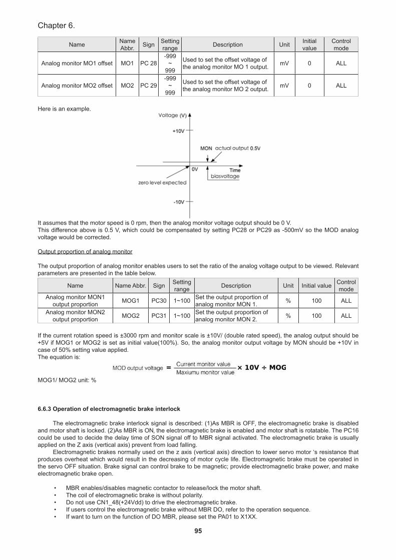
95
Chapter 6.
Name Name Abbr. Sign Setting
range Description Unit Initial value
Control mode
Analog monitor MO1 offset MO1 PC 28-999
~999
Used to set the offset voltage of the analog monitor MO 1 output. mV 0 ALL
Analog monitor MO2 offset MO2 PC 29-999
~999
Used to set the offset voltage of the analog monitor MO 2 output. mV 0 ALL
Here is an example.
It assumes that the motor speed is 0 rpm, then the analog monitor voltage output should be 0 V.This difference above is 0.5 V, which could be compensated by setting PC28 or PC29 as -500mV so the MOD analog voltage would be corrected.
Output proportion of analog monitor
The output proportion of analog monitor enables users to set the ratio of the analog voltage output to be viewed. Relevant parameters are presented in the table below.
Name Name Abbr. Sign Setting range Description Unit Initial value Control
modeAnalog monitor MON1
output proportion MOG1 PC30 1~100 Set the output proportion of analog monitor MON 1. % 100 ALL
Analog monitor MON2 output proportion MOG2 PC31 1~100 Set the output proportion of
analog monitor MON 2. % 100 ALL
If the current rotation speed is ±3000 rpm and monitor scale is ±10V/ (double rated speed), the analog output should be +5V if MOG1 or MOG2 is set as initial value(100%). So, the analog monitor output voltage by MON should be +10V in case of 50% setting value applied.The equation is:
MOG1/ MOG2 unit: %
6.6.3 Operation of electromagnetic brake interlock
The electromagnetic brake interlock signal is described: (1)As MBR is OFF, the electromagnetic brake is disabled and motor shaft is locked. (2)As MBR is ON, the electromagnetic brake is enabled and motor shaft is rotatable. The PC16 could be used to decide the delay time of SON signal off to MBR signal activated. The electromagnetic brake is usually applied on the Z axis (vertical axis) prevent from load falling.
Electromagnetic brakes normally used on the z axis (vertical axis) direction to lower servo motor ‘s resistance that produces overheat which would result in the decreasing of motor cycle life. Electromagnetic brake must be operated in the servo OFF situation. Brake signal can control brake to be magnetic; provide electromagnetic brake power, and make electromagnetic brake open.
• MBR enables/disables magnetic contactor to release/lock the motor shaft.• The coil of electromagnetic brake is without polarity.• Do not use CN1_48(+24Vdd) to drive the electromagnetic brake.• If users control the electromagnetic brake without MBR DO, refer to the operation sequence.• If want to turn on the function of DO MBR, please set the PA01 to X1XX.
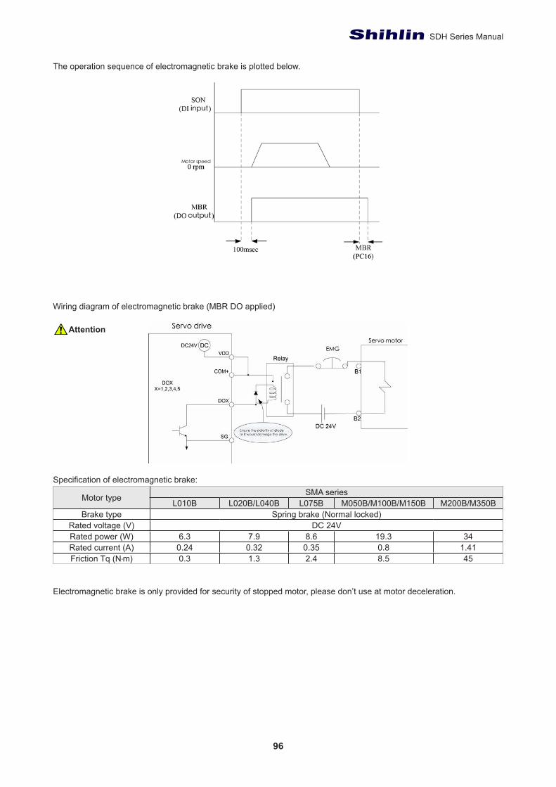
96
SDH Series Manual
The operation sequence of electromagnetic brake is plotted below.
Wiring diagram of electromagnetic brake (MBR DO applied)
Specification of electromagnetic brake:
Motor type SMA seriesL010B L020B/L040B L075B M050B/M100B/M150B M200B/M350B
Brake type Spring brake (Normal locked)Rated voltage (V) DC 24V
Rated power (W) 6.3 7.9 8.6 19.3 34Rated current (A) 0.24 0.32 0.35 0.8 1.41Friction Tq (N‧m) 0.3 1.3 2.4 8.5 45
Electromagnetic brake is only provided for security of stopped motor, please don’t use at motor deceleration.
Attention
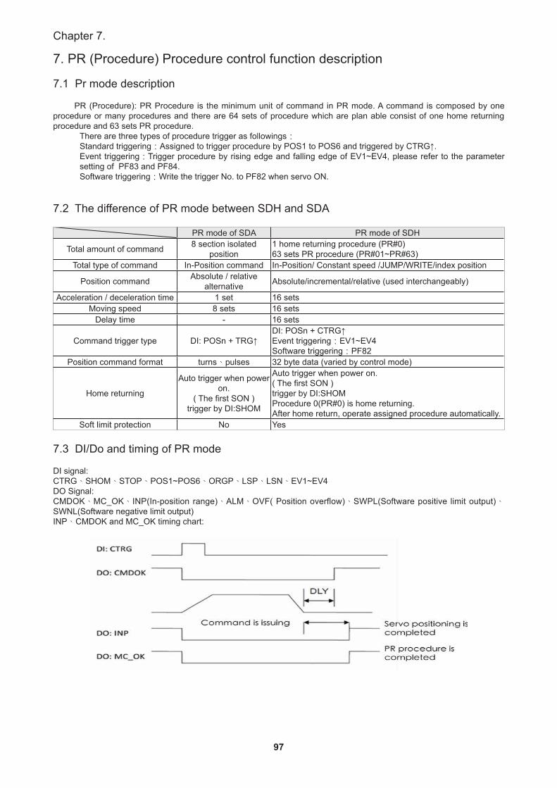
97
Chapter 7.
7. PR (Procedure) Procedure control function description
7.1 Pr mode description
PR (Procedure): PR Procedure is the minimum unit of command in PR mode. A command is composed by one procedure or many procedures and there are 64 sets of procedure which are plan able consist of one home returning procedure and 63 sets PR procedure.
There are three types of procedure trigger as followings:Standard triggering:Assigned to trigger procedure by POS1 to POS6 and triggered by CTRG↑.Event triggering:Trigger procedure by rising edge and falling edge of EV1~EV4, please refer to the parameter setting of PF83 and PF84.Software triggering:Write the trigger No. to PF82 when servo ON.
7.2 The difference of PR mode between SDH and SDA
PR mode of SDA PR mode of SDH
Total amount of command 8 section isolated position
1 home returning procedure (PR#0)63 sets PR procedure (PR#01~PR#63)
Total type of command In-Position command In-Position/ Constant speed /JUMP/WRITE/index position
Position command Absolute / relative alternative Absolute/incremental/relative (used interchangeably)
Acceleration / deceleration time 1 set 16 setsMoving speed 8 sets 16 sets
Delay time - 16 sets
Command trigger type DI: POSn + TRG↑DI: POSn + CTRG↑Event triggering:EV1~EV4Software triggering:PF82
Position command format turns、pulses 32 byte data (varied by control mode)
Home returning
Auto trigger when power on.
( The first SON )trigger by DI:SHOM
Auto trigger when power on.( The first SON )trigger by DI:SHOMProcedure 0(PR#0) is home returning.After home return, operate assigned procedure automatically.
Soft limit protection No Yes
7.3 DI/Do and timing of PR mode
DI signal:CTRG、SHOM、STOP、POS1~POS6、ORGP、LSP、LSN、EV1~EV4DO Signal:CMDOK、MC_OK、INP(In-position range)、ALM、OVF( Position overflow)、SWPL(Software positive limit output)、SWNL(Software negative limit output)INP、CMDOK and MC_OK timing chart:
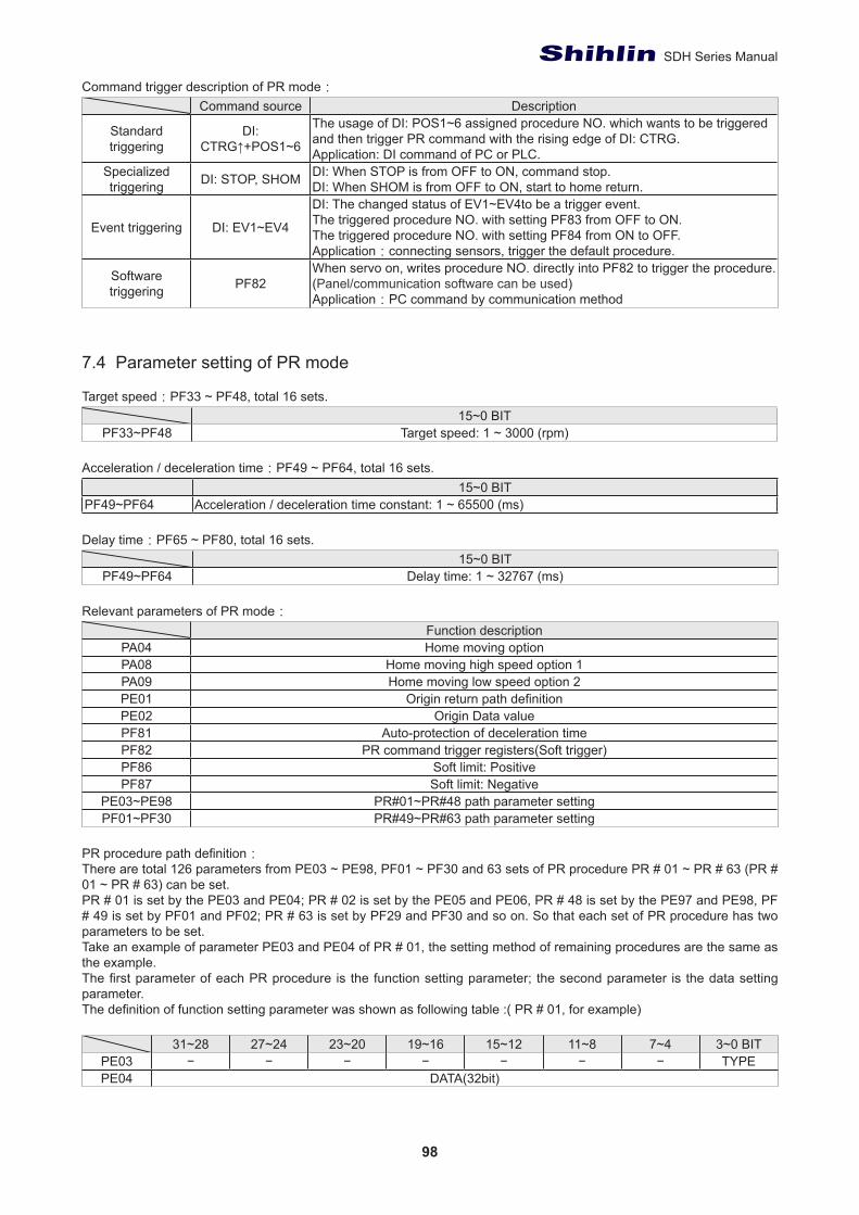
98
SDH Series Manual
Command trigger description of PR mode:Command source Description
Standard triggering
DI: CTRG↑+POS1~6
The usage of DI: POS1~6 assigned procedure NO. which wants to be triggered and then trigger PR command with the rising edge of DI: CTRG.Application: DI command of PC or PLC.
Specialized triggering DI: STOP, SHOM DI: When STOP is from OFF to ON, command stop.
DI: When SHOM is from OFF to ON, start to home return.
Event triggering DI: EV1~EV4
DI: The changed status of EV1~EV4to be a trigger event.The triggered procedure NO. with setting PF83 from OFF to ON.The triggered procedure NO. with setting PF84 from ON to OFF.Application:connecting sensors, trigger the default procedure.
Software triggering PF82
When servo on, writes procedure NO. directly into PF82 to trigger the procedure.(Panel/communication software can be used)Application:PC command by communication method
7.4 Parameter setting of PR mode
Target speed:PF33 ~ PF48, total 16 sets.15~0 BIT
PF33~PF48 Target speed: 1 ~ 3000 (rpm)
Acceleration / deceleration time:PF49 ~ PF64, total 16 sets.15~0 BIT
PF49~PF64 Acceleration / deceleration time constant: 1 ~ 65500 (ms)
Delay time:PF65 ~ PF80, total 16 sets.15~0 BIT
PF49~PF64 Delay time: 1 ~ 32767 (ms)
Relevant parameters of PR mode:Function description
PA04 Home moving optionPA08 Home moving high speed option 1PA09 Home moving low speed option 2PE01 Origin return path definitionPE02 Origin Data valuePF81 Auto-protection of deceleration timePF82 PR command trigger registers(Soft trigger)PF86 Soft limit: PositivePF87 Soft limit: Negative
PE03~PE98 PR#01~PR#48 path parameter settingPF01~PF30 PR#49~PR#63 path parameter setting
PR procedure path definition:There are total 126 parameters from PE03 ~ PE98, PF01 ~ PF30 and 63 sets of PR procedure PR # 01 ~ PR # 63 (PR # 01 ~ PR # 63) can be set.PR # 01 is set by the PE03 and PE04; PR # 02 is set by the PE05 and PE06, PR # 48 is set by the PE97 and PE98, PF # 49 is set by PF01 and PF02; PR # 63 is set by PF29 and PF30 and so on. So that each set of PR procedure has two parameters to be set.Take an example of parameter PE03 and PE04 of PR # 01, the setting method of remaining procedures are the same as the example.The first parameter of each PR procedure is the function setting parameter; the second parameter is the data setting parameter. The definition of function setting parameter was shown as following table :( PR # 01, for example)
31~28 27~24 23~20 19~16 15~12 11~8 7~4 3~0 BITPE03 − − − − − − − TYPEPE04 DATA(32bit)
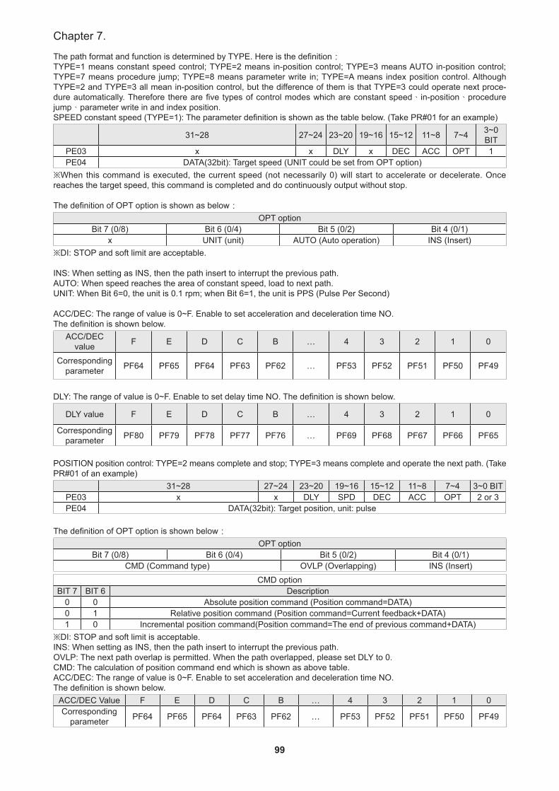
99
Chapter 7.
The path format and function is determined by TYPE. Here is the definition:TYPE=1 means constant speed control; TYPE=2 means in-position control; TYPE=3 means AUTO in-position control; TYPE=7 means procedure jump; TYPE=8 means parameter write in; TYPE=A means index position control. Although TYPE=2 and TYPE=3 all mean in-position control, but the difference of them is that TYPE=3 could operate next proce-dure automatically. Therefore there are five types of control modes which are constant speed、in-position、procedure jump、parameter write in and index position. SPEED constant speed (TYPE=1): The parameter definition is shown as the table below. (Take PR#01 for an example)
31~28 27~24 23~20 19~16 15~12 11~8 7~4 3~0 BIT
PE03 x x DLY x DEC ACC OPT 1PE04 DATA(32bit): Target speed (UNIT could be set from OPT option)
※When this command is executed, the current speed (not necessarily 0) will start to accelerate or decelerate. Once reaches the target speed, this command is completed and do continuously output without stop.
The definition of OPT option is shown as below:OPT option
Bit 7 (0/8) Bit 6 (0/4) Bit 5 (0/2) Bit 4 (0/1)x UNIT (unit) AUTO (Auto operation) INS (Insert)
※DI: STOP and soft limit are acceptable.
INS: When setting as INS, then the path insert to interrupt the previous path. AUTO: When speed reaches the area of constant speed, load to next path.UNIT: When Bit 6=0, the unit is 0.1 rpm; when Bit 6=1, the unit is PPS (Pulse Per Second)
ACC/DEC: The range of value is 0~F. Enable to set acceleration and deceleration time NO. The definition is shown below.
ACC/DEC value F E D C B … 4 3 2 1 0
Corresponding parameter PF64 PF65 PF64 PF63 PF62 … PF53 PF52 PF51 PF50 PF49
DLY: The range of value is 0~F. Enable to set delay time NO. The definition is shown below.
DLY value F E D C B … 4 3 2 1 0
Corresponding parameter PF80 PF79 PF78 PF77 PF76 … PF69 PF68 PF67 PF66 PF65
POSITION position control: TYPE=2 means complete and stop; TYPE=3 means complete and operate the next path. (Take PR#01 of an example)
31~28 27~24 23~20 19~16 15~12 11~8 7~4 3~0 BITPE03 x x DLY SPD DEC ACC OPT 2 or 3PE04 DATA(32bit): Target position, unit: pulse
The definition of OPT option is shown below:OPT option
Bit 7 (0/8) Bit 6 (0/4) Bit 5 (0/2) Bit 4 (0/1)CMD (Command type) OVLP (Overlapping) INS (Insert)
CMD optionBIT 7 BIT 6 Description
0 0 Absolute position command (Position command=DATA)0 1 Relative position command (Position command=Current feedback+DATA)1 0 Incremental position command(Position command=The end of previous command+DATA)
※DI: STOP and soft limit is acceptable.INS: When setting as INS, then the path insert to interrupt the previous path.OVLP: The next path overlap is permitted. When the path overlapped, please set DLY to 0. CMD: The calculation of position command end which is shown as above table.ACC/DEC: The range of value is 0~F. Enable to set acceleration and deceleration time NO. The definition is shown below.
ACC/DEC Value F E D C B … 4 3 2 1 0Corresponding
parameter PF64 PF65 PF64 PF63 PF62 … PF53 PF52 PF51 PF50 PF49
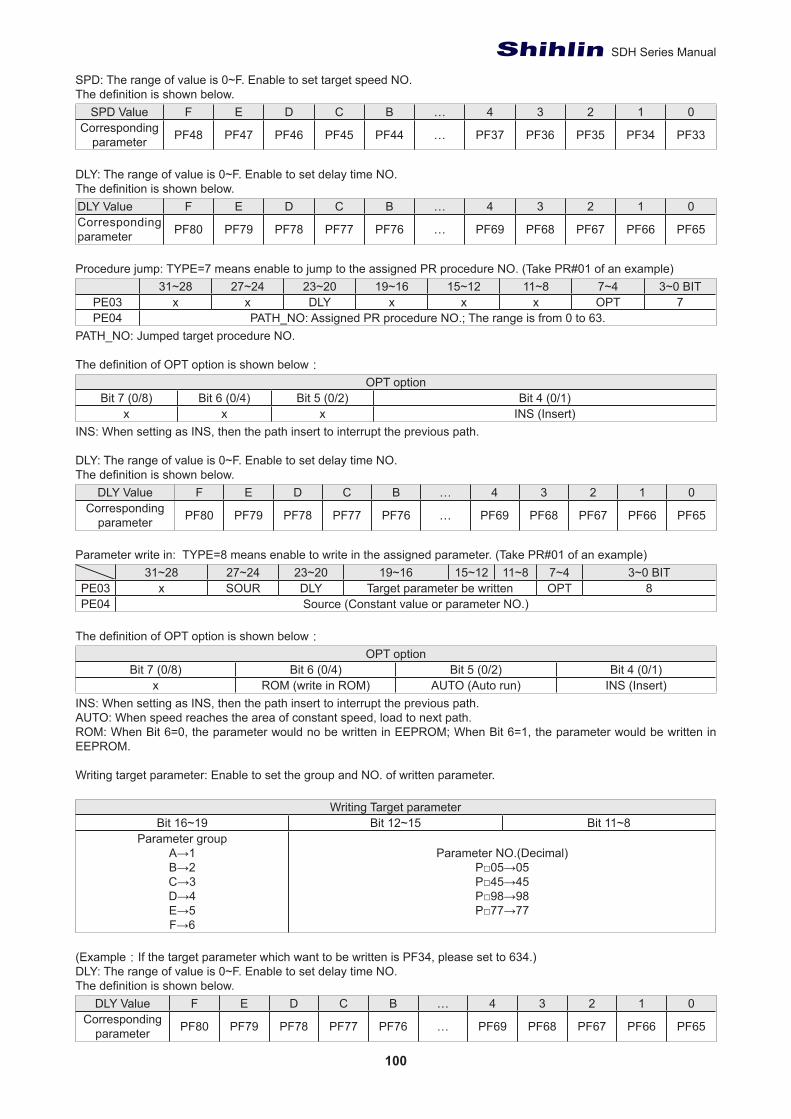
100
SDH Series Manual
SPD: The range of value is 0~F. Enable to set target speed NO. The definition is shown below.
SPD Value F E D C B … 4 3 2 1 0Corresponding
parameter PF48 PF47 PF46 PF45 PF44 … PF37 PF36 PF35 PF34 PF33
DLY: The range of value is 0~F. Enable to set delay time NO. The definition is shown below.DLY Value F E D C B … 4 3 2 1 0Corresponding parameter PF80 PF79 PF78 PF77 PF76 … PF69 PF68 PF67 PF66 PF65
Procedure jump: TYPE=7 means enable to jump to the assigned PR procedure NO. (Take PR#01 of an example)31~28 27~24 23~20 19~16 15~12 11~8 7~4 3~0 BIT
PE03 x x DLY x x x OPT 7PE04 PATH_NO: Assigned PR procedure NO.; The range is from 0 to 63.
PATH_NO: Jumped target procedure NO.
The definition of OPT option is shown below:OPT option
Bit 7 (0/8) Bit 6 (0/4) Bit 5 (0/2) Bit 4 (0/1)x x x INS (Insert)
INS: When setting as INS, then the path insert to interrupt the previous path.
DLY: The range of value is 0~F. Enable to set delay time NO. The definition is shown below.
DLY Value F E D C B … 4 3 2 1 0Corresponding
parameter PF80 PF79 PF78 PF77 PF76 … PF69 PF68 PF67 PF66 PF65
Parameter write in: TYPE=8 means enable to write in the assigned parameter. (Take PR#01 of an example)31~28 27~24 23~20 19~16 15~12 11~8 7~4 3~0 BIT
PE03 x SOUR DLY Target parameter be written OPT 8PE04 Source (Constant value or parameter NO.)
The definition of OPT option is shown below:OPT option
Bit 7 (0/8) Bit 6 (0/4) Bit 5 (0/2) Bit 4 (0/1)x ROM (write in ROM) AUTO (Auto run) INS (Insert)
INS: When setting as INS, then the path insert to interrupt the previous path. AUTO: When speed reaches the area of constant speed, load to next path.ROM: When Bit 6=0, the parameter would no be written in EEPROM; When Bit 6=1, the parameter would be written in EEPROM.
Writing target parameter: Enable to set the group and NO. of written parameter.
Writing Target parameterBit 16~19 Bit 12~15 Bit 11~8
Parameter groupA→1B→2C→3D→4E→5F→6
Parameter NO.(Decimal) P□05→05P□45→45P□98→98P□77→77
(Example:If the target parameter which want to be written is PF34, please set to 634.)DLY: The range of value is 0~F. Enable to set delay time NO. The definition is shown below.
DLY Value F E D C B … 4 3 2 1 0Corresponding
parameter PF80 PF79 PF78 PF77 PF76 … PF69 PF68 PF67 PF66 PF65
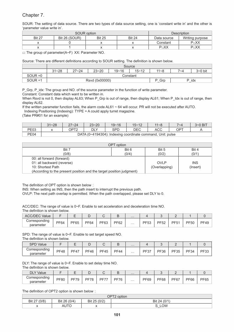
101
Chapter 7.
SOUR: The setting of data source. There are two types of data source setting, one is ‘constant write in’ and the other is ‘parameter value write in’.
SOUR option DescriptionBit 27 Bit 26 (SOUR) Bit 25 Bit 24 Data source Writing purpose
x 0 x x Constant P□XXx 1 x x P□XX P□XX
□: The group of parameter(A~F) XX: Parameter NO.
Source: There are different definitions according to SOUR setting. The definition is shown below.Source
31~28 27~24 23~20 19~16 15~12 11~8 7~4 3~0 bitSOUR =0 ConstantSOUR =1 Rsvd (0x00000) P_Grp P_idx
P_Grp, P_idx: The group and NO. of the source parameter in the function of write parameter.Constant: Constant data which want to be written in.When Rsvd is not 0, then display AL63; When P_Grp is out of range, then display AL61; When P_Idx is out of range, then display AL62.If the written parameter function fails, the alarm code AL61 ~ 64 will occur. PR will not be executed after AUTO. Indexing Positioning (Indexing): TYPE = A could apply turret magazine.(Take PR#01 for an example)
31~28 27~24 23~20 19~16 15~12 11~8 7~4 3~0 BITPE03 x OPT2 DLY SPD DEC ACC OPT APE04 DATA (0~4194304): Indexing coordinate command, Unit: pulse
OPT optionBit 7(0/8)
Bit 6(0/4)
Bit 5(0/2)
Bit 4(0/1)
00: all forward (forward)01: all backward (reverse)10: Shortest Path(According to the present position and the target position judgment)
OVLP(Overlapping)
INS (Insert)
The definition of OPT option is shown below:INS: When setting as INS, then the path insert to interrupt the previous path. OVLP: The next path overlap is permitted. When the path overlapped, please set DLY to 0.
ACC/DEC: The range of value is 0~F. Enable to set acceleration and deceleration time NO. The definition is shown below.
ACC/DEC Value F E D C B … 4 3 2 1 0Corresponding
parameter PF64 PF65 PF64 PF63 PF62 … PF53 PF52 PF51 PF50 PF49
SPD: The range of value is 0~F. Enable to set target speed NO. The definition is shown below.
SPD Value F E D C B … 4 3 2 1 0Corresponding
parameter PF48 PF47 PF46 PF45 PF44 … PF37 PF36 PF35 PF34 PF33
DLY: The range of value is 0~F. Enable to set delay time NO. The definition is shown below.
DLY Value F E D C B … 4 3 2 1 0Corresponding
parameter PF80 PF79 PF78 PF77 PF76 … PF69 PF68 PF67 PF66 PF65
The definition of OPT2 option is shown below:OPT2 option
Bit 27 (0/8) Bit 26 (0/4) Bit 25 (0/2) Bit 24 (0/1)x AUTO x S_LOW
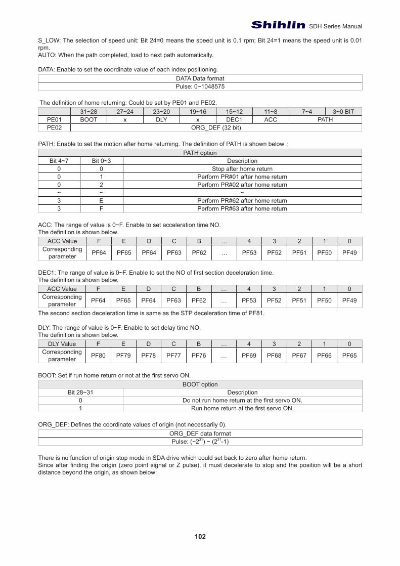
102
SDH Series Manual
S_LOW: The selection of speed unit: Bit 24=0 means the speed unit is 0.1 rpm; Bit 24=1 means the speed unit is 0.01 rpm.AUTO: When the path completed, load to next path automatically.
DATA: Enable to set the coordinate value of each index positioning.DATA Data formatPulse: 0~1048575
The definition of home returning: Could be set by PE01 and PE02.31~28 27~24 23~20 19~16 15~12 11~8 7~4 3~0 BIT
PE01 BOOT x DLY x DEC1 ACC PATHPE02 ORG_DEF (32 bit)
PATH: Enable to set the motion after home returning. The definition of PATH is shown below:PATH option
Bit 4~7 Bit 0~3 Description0 0 Stop after home return0 1 Perform PR#01 after home return0 2 Perform PR#02 after home return~ ~ ~3 E Perform PR#62 after home return3 F Perform PR#63 after home return
ACC: The range of value is 0~F. Enable to set acceleration time NO. The definition is shown below.
ACC Value F E D C B … 4 3 2 1 0Corresponding
parameter PF64 PF65 PF64 PF63 PF62 … PF53 PF52 PF51 PF50 PF49
DEC1: The range of value is 0~F. Enable to set the NO of first section deceleration time. The definition is shown below.
ACC Value F E D C B … 4 3 2 1 0Corresponding
parameter PF64 PF65 PF64 PF63 PF62 … PF53 PF52 PF51 PF50 PF49
The second section deceleration time is same as the STP deceleration time of PF81.
DLY: The range of value is 0~F. Enable to set delay time NO. The definition is shown below.
DLY Value F E D C B … 4 3 2 1 0Corresponding
parameter PF80 PF79 PF78 PF77 PF76 … PF69 PF68 PF67 PF66 PF65
BOOT: Set if run home return or not at the first servo ON.BOOT option
Bit 28~31 Description0 Do not run home return at the first servo ON.1 Run home return at the first servo ON.
ORG_DEF: Defines the coordinate values of origin (not necessarily 0).ORG_DEF data formatPulse: (−231) ~ (231-1)
There is no function of origin stop mode in SDA drive which could set back to zero after home return. Since after finding the origin (zero point signal or Z pulse), it must decelerate to stop and the position will be a short distance beyond the origin, as shown below:

103
Chapter 7.
If PATH=0, the position will not move to origin point.If PATH=A, the position will move to origin point and run PR#A automatically. Please set PR#A as absolute command of positioning control and let command =ORG_DEF.
There is no definition of offset about home return, where rather using the PATH to be specified as an offset value of a path.It is recommended to use absolute position command and let command value = offset (absolute value).
7.5 The procedure connection status
There are 63 groups procedure of PR mode could be set to five control types as constant speed, position, path jumping, parameters writing-in and index positioning.The 63 sets procedures consist of various different combination of control mode, PR mode of SDH provides three procedure connection functions such as AUTO (perform next procedure automatically), and insert to interrupt (INS) and overlapping (OVLP).AUTO and INS could be set at five-control mode, but OVLP just could be performed at positioning control, which continue positioning control mode.
Here are descriptions to three different connections:(a) Sequence command:
If INS and OVLP are not be set at PR mode, the procedure flow would be in original sequence. But if AUTO has been set at the previous procedure, the procedures will continuous to perform after previous procedure completed including the setting delay time.
(b) Overlapping command: In the OVLP just could be performed at positioning control which continue positioning control mode. OVLP could be set at both two procedures are in position control mode to smooth the connection of procedure and reduce vibrations.
(c) Insert command:Insert command means command is interrupted before completed in case of the command is replaced or combined by another command.
The final results will vary depending on the control type.Sequence commands: Using the AUTO function to create a fixed procedure command combination.
PR#12 ( AUTO position control、Incremental position stroke:104857600 pulse、delay time: 200 ms ) → PR#13 ( position control、Absolute position:0 pulse )As shown as the following chart that it is a typical sequence command for the situation of positioning control continuous positioning control. The delay time is calculated after position completed.
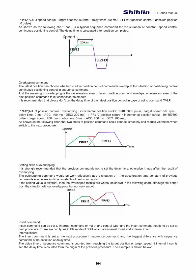
104
SDH Series Manual
PR#12(AUTO speed control、target speed:2000 rpm、delay time: 200 ms) → PR#13(position control、absolute position : 0 pulse)As shown as the following chart that it is a typical sequence command for the situation of constant speed control continuous positioning control. The delay time is calculated after position completed.
Overlapping command:The latest position can choose whether to allow position control commands overlap at the situation of positioning control continuous positioning control in sequence command. And the meaning of overlapping is the deceleration area of latest position command overlaps acceleration area of the next position command to let connection be smooth.It is recommended that please don’t set the delay time of the latest position control in case of using command OVLP.
PR#12(AUTO position control、overlapping、incremental position stroke: 104857600 pulse、target speed: 500 rpm、delay time: 0 ms、ACC: 400 ms、DEC: 200 ms) → PR#13(position control、incremental position stroke: 104857600 pulse、target speed: 700 rpm、delay time: 0 ms 、ACC: 200 ms、DEC: 200 ms).As shown as the following chart that two steps of position command could connect smoothly and reduce vibrations when switch to the next procedure.
Setting skills of overlapping:It is strongly recommended that the previous commands not to set the delay time, otherwise it may affect the result of overlapping.The overlapping command would be work effectively at the situation of “ the deceleration time constant of previous commands = acceleration time constants of next commands”.If the setting value is different, then the overlapped results are worse, as shown in the following chart, although still better than the situation without overlapping, but not very smooth.
Insert command:Insert command can be set to interrupt command or not at any control type, and the insert command needs to be set at next procedure. There are two types in PR mode of SDH which are internal insert and external insert.Internal insert: The insert command is set at the next procedure in sequence command and the biggest difference with sequence command is the definition of delay time.The delay time of sequence command is counted from reaching the target position or target speed, if internal insert is set, the delay time is counted form the origin of the previous procedure. The example is shown below:
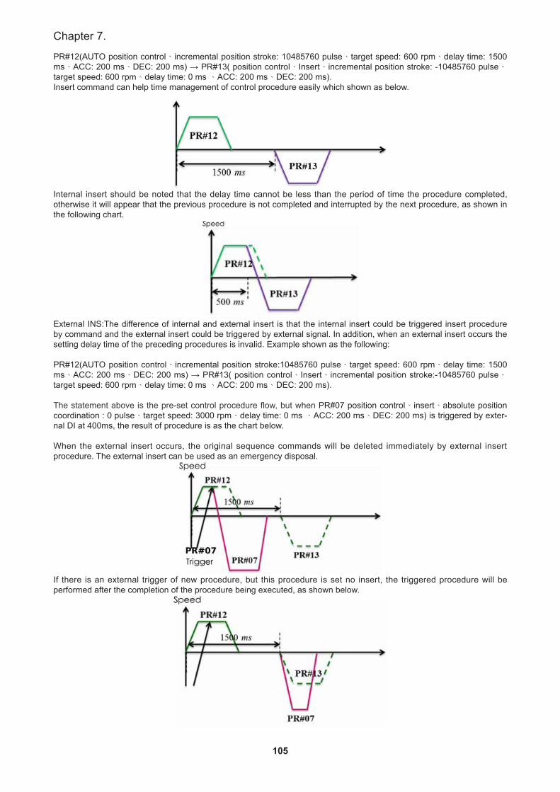
105
Chapter 7.
PR#12(AUTO position control、incremental position stroke: 10485760 pulse、target speed: 600 rpm、delay time: 1500 ms、ACC: 200 ms、DEC: 200 ms) → PR#13( position control、Insert、incremental position stroke: -10485760 pulse、target speed: 600 rpm、delay time: 0 ms 、ACC: 200 ms、DEC: 200 ms).Insert command can help time management of control procedure easily which shown as below.
Internal insert should be noted that the delay time cannot be less than the period of time the procedure completed, otherwise it will appear that the previous procedure is not completed and interrupted by the next procedure, as shown in the following chart.
External INS:The difference of internal and external insert is that the internal insert could be triggered insert procedure by command and the external insert could be triggered by external signal. In addition, when an external insert occurs the setting delay time of the preceding procedures is invalid. Example shown as the following:
PR#12(AUTO position control、incremental position stroke:10485760 pulse、target speed: 600 rpm、delay time: 1500 ms、ACC: 200 ms、DEC: 200 ms) → PR#13( position control、Insert、incremental position stroke:-10485760 pulse、target speed: 600 rpm、delay time: 0 ms 、ACC: 200 ms、DEC: 200 ms).
The statement above is the pre-set control procedure flow, but when PR#07 position control、insert、absolute position coordination : 0 pulse、target speed: 3000 rpm、delay time: 0 ms 、ACC: 200 ms、DEC: 200 ms) is triggered by exter-nal DI at 400ms, the result of procedure is as the chart below.
When the external insert occurs, the original sequence commands will be deleted immediately by external insert procedure. The external insert can be used as an emergency disposal.
If there is an external trigger of new procedure, but this procedure is set no insert, the triggered procedure will be performed after the completion of the procedure being executed, as shown below.
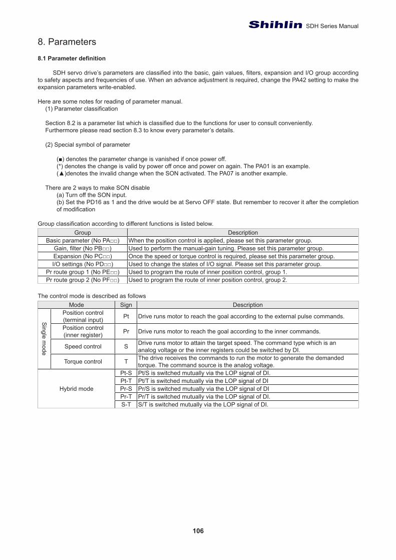
106
SDH Series Manual
8. Parameters
8.1 Parameter definition
SDH servo drive’s parameters are classified into the basic, gain values, filters, expansion and I/O group according to safety aspects and frequencies of use. When an advance adjustment is required, change the PA42 setting to make the expansion parameters write-enabled.
Here are some notes for reading of parameter manual.(1) Parameter classification
Section 8.2 is a parameter list which is classified due to the functions for user to consult conveniently. Furthermore please read section 8.3 to know every parameter’s details.
(2) Special symbol of parameter
(■) denotes the parameter change is vanished if once power off.(*) denotes the change is valid by power off once and power on again. The PA01 is an example.(▲)denotes the invalid change when the SON activated. The PA07 is another example.
There are 2 ways to make SON disable(a) Turn off the SON input.(b) Set the PD16 as 1 and the drive would be at Servo OFF state. But remember to recover it after the completion of modification
Group classification according to different functions is listed below.Group Description
Basic parameter (No PA□□) When the position control is applied, please set this parameter group.Gain, filter (No PB□□) Used to perform the manual-gain tuning. Please set this parameter group.Expansion (No PC□□) Once the speed or torque control is required, please set this parameter group.I/O settings (No PD□□) Used to change the states of I/O signal. Please set this parameter group.
Pr route group 1 (No PE□□) Used to program the route of inner position control, group 1.Pr route group 2 (No PF□□) Used to program the route of inner position control, group 2.
The control mode is described as followsMode Sign Description
Single m
ode
Position control(terminal input) Pt Drive runs motor to reach the goal according to the external pulse commands.
Position control(inner register) Pr Drive runs motor to reach the goal according to the inner commands.
Speed control S Drive runs motor to attain the target speed. The command type which is ananalog voltage or the inner registers could be switched by DI.
Torque control T The drive receives the commands to run the motor to generate the demandedtorque. The command source is the analog voltage.
Hybrid mode
Pt-S Pt/S is switched mutually via the LOP signal of DI.Pt-T Pt/T is switched mutually via the LOP signal of DIPr-S Pr/S is switched mutually via the LOP signal of DIPr-T Pr/T is switched mutually via the LOP signal of DI.S-T S/T is switched mutually via the LOP signal of DI.
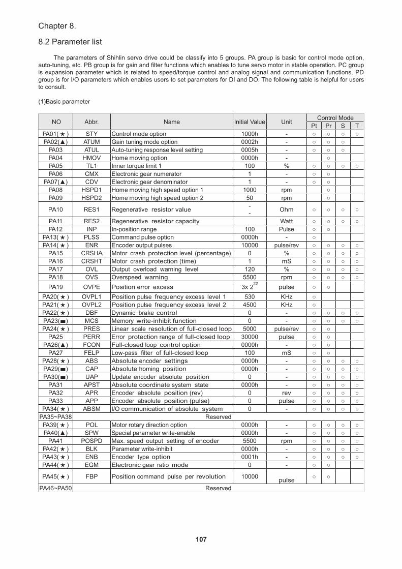
107
Chapter 8.
8.2 Parameter list
The parameters of Shihlin servo drive could be classify into 5 groups. PA group is basic for control mode option, auto-tuning, etc. PB group is for gain and filter functions which enables to tune servo motor in stable operation. PC group is expansion parameter which is related to speed/torque control and analog signal and communication functions. PD group is for I/O parameters which enables users to set parameters for DI and DO. The following table is helpful for users to consult.
(1)Basic parameter
NO Abbr. Name Initial Value Unit Control ModePt Pr S T
PA01( ★ ) STY Control mode option 1000h - ○ ○ ○ ○PA02(▲) ATUM Gain tuning mode option 0002h - ○ ○ ○
PA03 ATUL Auto-tuning response level setting 0005h - ○ ○ ○PA04 HMOV Home moving option 0000h - ○PA05 TL1 Inner torque limit 1 100 % ○ ○ ○ ○PA06 CMX Electronic gear numerator 1 - ○ ○
PA07(▲) CDV Electronic gear denominator 1 - ○ ○PA08 HSPD1 Home moving high speed option 1 1000 rpm ○PA09 HSPD2 Home moving high speed option 2 50 rpm ○
PA10 RES1 Regenerative resistor value -- Ohm ○ ○ ○ ○
PA11 RES2 Regenerative resistor capacity Watt ○ ○ ○ ○PA12 INP In-position range 100 Pulse ○ ○
PA13( ★ ) PLSS Command pulse option 0000h - ○PA14( ★ ) ENR Encoder output pulses 10000 pulse/rev ○ ○ ○ ○
PA15 CRSHA Motor crash protection level (percentage) 0 % ○ ○ ○ ○PA16 CRSHT Motor crash protection (time) 1 mS ○ ○ ○ ○PA17 OVL Output overload warning level 120 % ○ ○ ○ ○PA18 OVS Overspeed warning 5500 rpm ○ ○ ○ ○PA19 OVPE Position error excess 3x 2
22pulse ○ ○
PA20( ★ ) OVPL1 Position pulse frequency excess level 1 530 KHz ○PA21( ★ ) OVPL2 Position pulse frequency excess level 2 4500 KHz ○PA22( ★ ) DBF Dynamic brake control 0 - ○ ○ ○ ○PA23(■) MCS Memory write-inhibit function 0 - ○ ○ ○ ○PA24( ★ ) PRES Linear scale resolution of full-closed loop 5000 pulse/rev ○ ○
PA25 PERR Error protection range of full-closed loop 30000 pulse ○ ○PA26(▲) FCON Full-closed loop control option 0000h - ○ ○
PA27 FELP Low-pass filter of full-closed loop 100 mS ○ ○PA28( ★ ) ABS Absolute encoder settings 0000h - ○ ○ ○ ○PA29(■) CAP Absolute homing position 0000h - ○ ○ ○ ○PA30(■) UAP Update encoder absolute position 0 - ○ ○ ○ ○
PA31 APST Absolute coordinate system state 0000h - ○ ○ ○ ○PA32 APR Encoder absolute position (rev) 0 rev ○ ○ ○ ○PA33 APP Encoder absolute position (pulse) 0 pulse ○ ○ ○ ○
PA34( ★ ) ABSM I/O communication of absolute system 0 - ○ ○ ○ ○PA35~PA38 ReservedPA39( ★ ) POL Motor rotary direction option 0000h - ○ ○ ○ ○PA40(▲) SPW Special parameter write-enable 0000h - ○ ○ ○ ○
PA41 POSPD Max. speed output setting of encoder 5500 rpm ○ ○ ○ ○PA42( ★ ) BLK Parameter write-inhibit 0000h - ○ ○ ○ ○PA43( ★ ) ENB Encoder type option 0001h - ○ ○ ○ ○PA44( ★ ) EGM Electronic gear ratio mode 0 - ○ ○
PA45( ★ ) FBP Position command pulse per revolution 10000 pulse ○ ○
PA46~PA50 Reserved
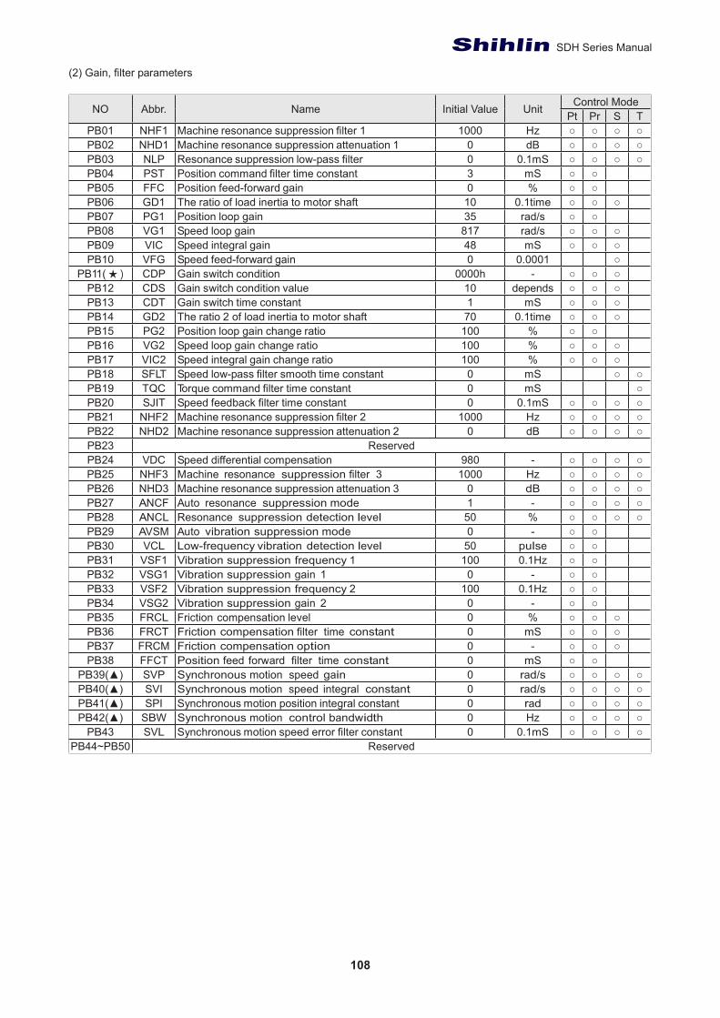
108
SDH Series Manual
(2) Gain, filter parameters
NO Abbr. Name Initial Value Unit Control ModePt Pr S T
PB01 NHF1 Machine resonance suppression filter 1 1000 Hz ○ ○ ○ ○PB02 NHD1 Machine resonance suppression attenuation 1 0 dB ○ ○ ○ ○PB03 NLP Resonance suppression low-pass filter 0 0.1mS ○ ○ ○ ○PB04 PST Position command filter time constant 3 mS ○ ○PB05 FFC Position feed-forward gain 0 % ○ ○PB06 GD1 The ratio of load inertia to motor shaft 10 0.1time ○ ○ ○PB07 PG1 Position loop gain 35 rad/s ○ ○PB08 VG1 Speed loop gain 817 rad/s ○ ○ ○PB09 VIC Speed integral gain 48 mS ○ ○ ○PB10 VFG Speed feed-forward gain 0 0.0001 ○
PB11( ★ ) CDP Gain switch condition 0000h - ○ ○ ○PB12 CDS Gain switch condition value 10 depends ○ ○ ○PB13 CDT Gain switch time constant 1 mS ○ ○ ○PB14 GD2 The ratio 2 of load inertia to motor shaft 70 0.1time ○ ○ ○PB15 PG2 Position loop gain change ratio 100 % ○ ○PB16 VG2 Speed loop gain change ratio 100 % ○ ○ ○PB17 VIC2 Speed integral gain change ratio 100 % ○ ○ ○PB18 SFLT Speed low-pass filter smooth time constant 0 mS ○ ○PB19 TQC Torque command filter time constant 0 mS ○PB20 SJIT Speed feedback filter time constant 0 0.1mS ○ ○ ○ ○PB21 NHF2 Machine resonance suppression filter 2 1000 Hz ○ ○ ○ ○PB22 NHD2 Machine resonance suppression attenuation 2 0 dB ○ ○ ○ ○PB23 ReservedPB24 VDC Speed differential compensation 980 - ○ ○ ○ ○PB25 NHF3 Machine resonance suppression filter 3 1000 Hz ○ ○ ○ ○PB26 NHD3 Machine resonance suppression attenuation 3 0 dB ○ ○ ○ ○PB27 ANCF Auto resonance suppression mode 1 - ○ ○ ○ ○PB28 ANCL Resonance suppression detection level 50 % ○ ○ ○ ○PB29 AVSM Auto vibration suppression mode 0 - ○ ○PB30 VCL Low-frequency vibration detection level 50 pulse ○ ○PB31 VSF1 Vibration suppression frequency 1 100 0.1Hz ○ ○PB32 VSG1 Vibration suppression gain 1 0 - ○ ○PB33 VSF2 Vibration suppression frequency 2 100 0.1Hz ○ ○PB34 VSG2 Vibration suppression gain 2 0 - ○ ○PB35 FRCL Friction compensation level 0 % ○ ○ ○PB36 FRCT Friction compensation filter time constant 0 mS ○ ○ ○PB37 FRCM Friction compensation option 0 - ○ ○ ○PB38 FFCT Position feed forward filter time constant 0 mS ○ ○
PB39(▲) SVP Synchronous motion speed gain 0 rad/s ○ ○ ○ ○PB40(▲) SVI Synchronous motion speed integral constant 0 rad/s ○ ○ ○ ○PB41(▲) SPI Synchronous motion position integral constant 0 rad ○ ○ ○ ○PB42(▲) SBW Synchronous motion control bandwidth 0 Hz ○ ○ ○ ○
PB43 SVL Synchronous motion speed error filter constant 0 0.1mS ○ ○ ○ ○PB44~PB50 Reserved
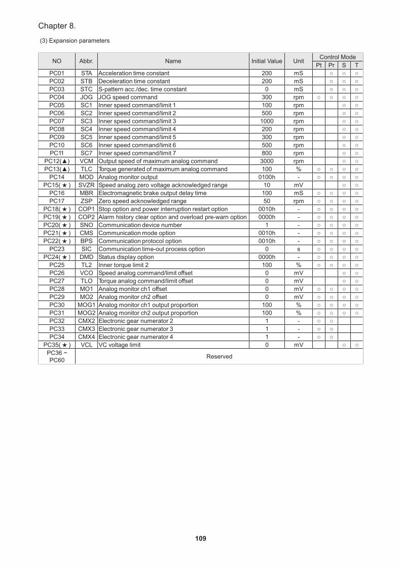
109
Chapter 8.
(3) Expansion parameters
NO Abbr. Name Initial Value Unit Control ModePt Pr S T
PC01 STA Acceleration time constant 200 mS ○ ○ ○PC02 STB Deceleration time constant 200 mS ○ ○ ○PC03 STC S-pattern acc./dec. time constant 0 mS ○ ○ ○PC04 JOG JOG speed command 300 rpm ○ ○ ○ ○PC05 SC1 Inner speed command/limit 1 100 rpm ○ ○PC06 SC2 Inner speed command/limit 2 500 rpm ○ ○PC07 SC3 Inner speed command/limit 3 1000 rpm ○ ○PC08 SC4 Inner speed command/limit 4 200 rpm ○ ○PC09 SC5 Inner speed command/limit 5 300 rpm ○ ○PC10 SC6 Inner speed command/limit 6 500 rpm ○ ○PC11 SC7 Inner speed command/limit 7 800 rpm ○ ○
PC12(▲) VCM Output speed of maximum analog command 3000 rpm ○ ○PC13(▲) TLC Torque generated of maximum analog command 100 % ○ ○ ○ ○
PC14 MOD Analog monitor output 0100h - ○ ○ ○ ○PC15( ★ ) SVZR Speed analog zero voltage acknowledged range 10 mV ○ ○
PC16 MBR Electromagnetic brake output delay time 100 mS ○ ○ ○ ○PC17 ZSP Zero speed acknowledged range 50 rpm ○ ○ ○ ○
PC18( ★ ) COP1 Stop option and power interruption restart option 0010h - ○ ○ ○ ○PC19( ★ ) COP2 Alarm history clear option and overload pre-warn option 0000h - ○ ○ ○ ○PC20( ★ ) SNO Communication device number 1 - ○ ○ ○ ○PC21( ★ ) CMS Communication mode option 0010h - ○ ○ ○ ○PC22( ★ ) BPS Communication protocol option 0010h - ○ ○ ○ ○
PC23 SIC Communication time-out process option 0 s ○ ○ ○ ○PC24( ★ ) DMD Status display option 0000h - ○ ○ ○ ○
PC25 TL2 Inner torque limit 2 100 % ○ ○ ○ ○PC26 VCO Speed analog command/limit offset 0 mV ○ ○PC27 TLO Torque analog command/limit offset 0 mV ○ ○PC28 MO1 Analog monitor ch1 offset 0 mV ○ ○ ○ ○PC29 MO2 Analog monitor ch2 offset 0 mV ○ ○ ○ ○PC30 MOG1 Analog monitor ch1 output proportion 100 % ○ ○ ○ ○PC31 MOG2 Analog monitor ch2 output proportion 100 % ○ ○ ○ ○PC32 CMX2 Electronic gear numerator 2 1 - ○ ○PC33 CMX3 Electronic gear numerator 3 1 - ○ ○PC34 CMX4 Electronic gear numerator 4 1 - ○ ○
PC35( ★ ) VCL VC voltage limit 0 mV ○ ○PC36 ~ PC60 Reserved
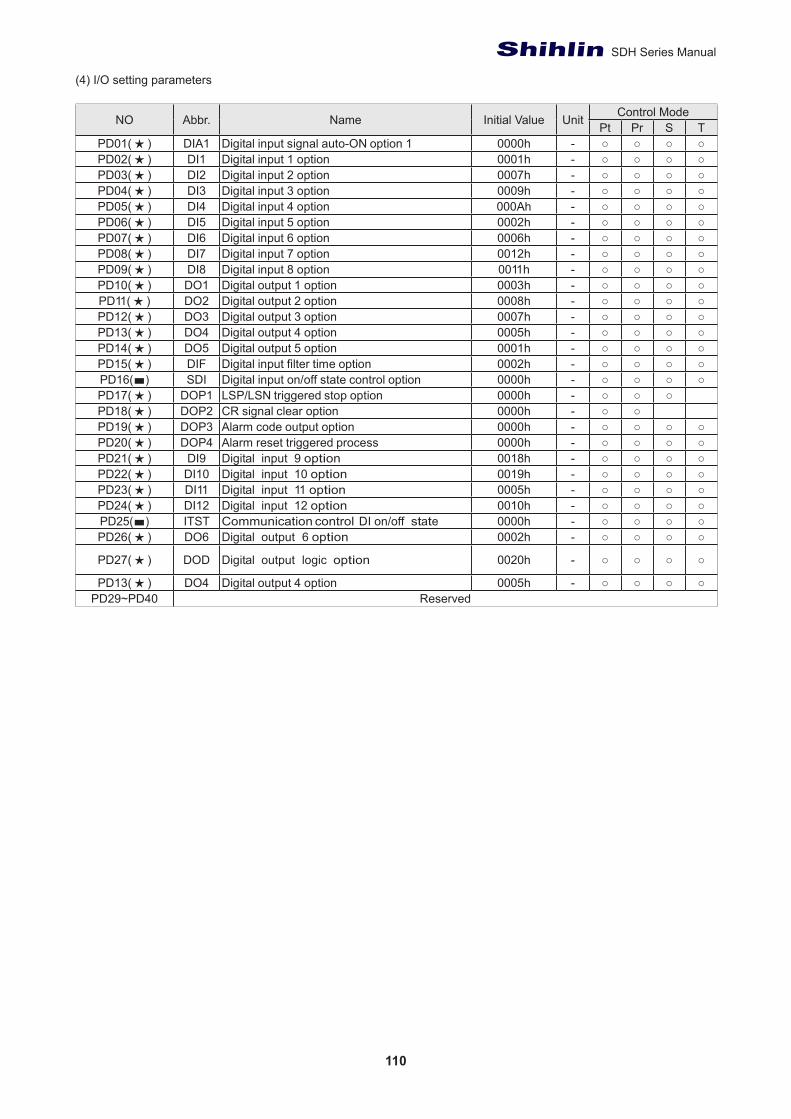
110
SDH Series Manual
(4) I/O setting parameters
NO Abbr. Name Initial Value Unit Control ModePt Pr S T
PD01( ★ ) DIA1 Digital input signal auto-ON option 1 0000h - ○ ○ ○ ○PD02( ★ ) DI1 Digital input 1 option 0001h - ○ ○ ○ ○PD03( ★ ) DI2 Digital input 2 option 0007h - ○ ○ ○ ○PD04( ★ ) DI3 Digital input 3 option 0009h - ○ ○ ○ ○PD05( ★ ) DI4 Digital input 4 option 000Ah - ○ ○ ○ ○PD06( ★ ) DI5 Digital input 5 option 0002h - ○ ○ ○ ○PD07( ★ ) DI6 Digital input 6 option 0006h - ○ ○ ○ ○PD08( ★ ) DI7 Digital input 7 option 0012h - ○ ○ ○ ○PD09( ★ ) DI8 Digital input 8 option 0011h - ○ ○ ○ ○PD10( ★ ) DO1 Digital output 1 option 0003h - ○ ○ ○ ○PD11( ★ ) DO2 Digital output 2 option 0008h - ○ ○ ○ ○PD12( ★ ) DO3 Digital output 3 option 0007h - ○ ○ ○ ○PD13( ★ ) DO4 Digital output 4 option 0005h - ○ ○ ○ ○PD14( ★ ) DO5 Digital output 5 option 0001h - ○ ○ ○ ○PD15( ★ ) DIF Digital input filter time option 0002h - ○ ○ ○ ○PD16(■) SDI Digital input on/off state control option 0000h - ○ ○ ○ ○PD17( ★ ) DOP1 LSP/LSN triggered stop option 0000h - ○ ○ ○PD18( ★ ) DOP2 CR signal clear option 0000h - ○ ○PD19( ★ ) DOP3 Alarm code output option 0000h - ○ ○ ○ ○PD20( ★ ) DOP4 Alarm reset triggered process 0000h - ○ ○ ○ ○PD21( ★ ) DI9 Digital input 9 option 0018h - ○ ○ ○ ○PD22( ★ ) DI10 Digital input 10 option 0019h - ○ ○ ○ ○PD23( ★ ) DI11 Digital input 11 option 0005h - ○ ○ ○ ○PD24( ★ ) DI12 Digital input 12 option 0010h - ○ ○ ○ ○PD25(■) ITST Communication control DI on/off state 0000h - ○ ○ ○ ○PD26( ★ ) DO6 Digital output 6 option 0002h - ○ ○ ○ ○
PD27( ★ ) DOD Digital output logic option 0020h - ○ ○ ○ ○
PD13( ★ ) DO4 Digital output 4 option 0005h - ○ ○ ○ ○PD29~PD40 Reserved
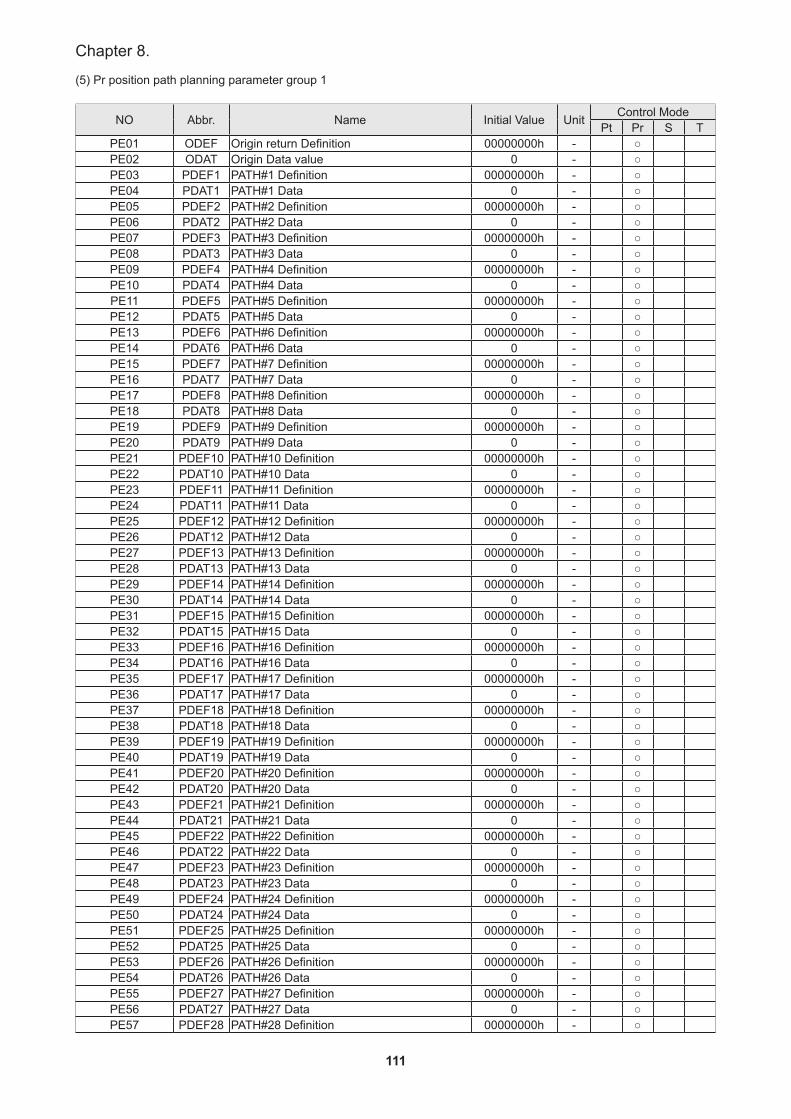
111
Chapter 8.
(5) Pr position path planning parameter group 1
NO Abbr. Name Initial Value Unit Control ModePt Pr S T
PE01 ODEF Origin return Definition 00000000h - ○PE02 ODAT Origin Data value 0 - ○PE03 PDEF1 PATH#1 Definition 00000000h - ○PE04 PDAT1 PATH#1 Data 0 - ○PE05 PDEF2 PATH#2 Definition 00000000h - ○PE06 PDAT2 PATH#2 Data 0 - ○PE07 PDEF3 PATH#3 Definition 00000000h - ○PE08 PDAT3 PATH#3 Data 0 - ○PE09 PDEF4 PATH#4 Definition 00000000h - ○PE10 PDAT4 PATH#4 Data 0 - ○PE11 PDEF5 PATH#5 Definition 00000000h - ○PE12 PDAT5 PATH#5 Data 0 - ○PE13 PDEF6 PATH#6 Definition 00000000h - ○PE14 PDAT6 PATH#6 Data 0 - ○PE15 PDEF7 PATH#7 Definition 00000000h - ○PE16 PDAT7 PATH#7 Data 0 - ○PE17 PDEF8 PATH#8 Definition 00000000h - ○PE18 PDAT8 PATH#8 Data 0 - ○PE19 PDEF9 PATH#9 Definition 00000000h - ○PE20 PDAT9 PATH#9 Data 0 - ○PE21 PDEF10 PATH#10 Definition 00000000h - ○PE22 PDAT10 PATH#10 Data 0 - ○PE23 PDEF11 PATH#11 Definition 00000000h - ○PE24 PDAT11 PATH#11 Data 0 - ○PE25 PDEF12 PATH#12 Definition 00000000h - ○PE26 PDAT12 PATH#12 Data 0 - ○PE27 PDEF13 PATH#13 Definition 00000000h - ○PE28 PDAT13 PATH#13 Data 0 - ○PE29 PDEF14 PATH#14 Definition 00000000h - ○PE30 PDAT14 PATH#14 Data 0 - ○PE31 PDEF15 PATH#15 Definition 00000000h - ○PE32 PDAT15 PATH#15 Data 0 - ○PE33 PDEF16 PATH#16 Definition 00000000h - ○PE34 PDAT16 PATH#16 Data 0 - ○PE35 PDEF17 PATH#17 Definition 00000000h - ○PE36 PDAT17 PATH#17 Data 0 - ○PE37 PDEF18 PATH#18 Definition 00000000h - ○PE38 PDAT18 PATH#18 Data 0 - ○PE39 PDEF19 PATH#19 Definition 00000000h - ○PE40 PDAT19 PATH#19 Data 0 - ○PE41 PDEF20 PATH#20 Definition 00000000h - ○PE42 PDAT20 PATH#20 Data 0 - ○PE43 PDEF21 PATH#21 Definition 00000000h - ○PE44 PDAT21 PATH#21 Data 0 - ○PE45 PDEF22 PATH#22 Definition 00000000h - ○PE46 PDAT22 PATH#22 Data 0 - ○PE47 PDEF23 PATH#23 Definition 00000000h - ○PE48 PDAT23 PATH#23 Data 0 - ○PE49 PDEF24 PATH#24 Definition 00000000h - ○PE50 PDAT24 PATH#24 Data 0 - ○PE51 PDEF25 PATH#25 Definition 00000000h - ○PE52 PDAT25 PATH#25 Data 0 - ○PE53 PDEF26 PATH#26 Definition 00000000h - ○PE54 PDAT26 PATH#26 Data 0 - ○PE55 PDEF27 PATH#27 Definition 00000000h - ○PE56 PDAT27 PATH#27 Data 0 - ○PE57 PDEF28 PATH#28 Definition 00000000h - ○
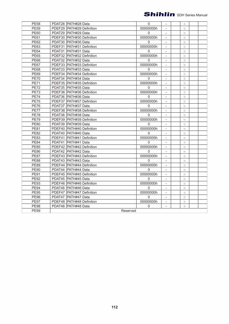
112
SDH Series Manual
PE58 PDAT28 PATH#28 Data 0 - ○PE59 PDEF29 PATH#29 Definition 00000000h - ○PE60 PDAT29 PATH#29 Data 0 - ○PE61 PDEF30 PATH#30 Definition 00000000h - ○PE62 PDAT30 PATH#30 Data 0 - ○PE63 PDEF31 PATH#31 Definition 00000000h - ○PE64 PDAT31 PATH#31 Data 0 - ○PE65 PDEF32 PATH#32 Definition 00000000h - ○PE66 PDAT32 PATH#32 Data 0 - ○PE67 PDEF33 PATH#33 Definition 00000000h - ○PE68 PDAT33 PATH#33 Data 0 - ○PE69 PDEF34 PATH#34 Definition 00000000h - ○PE70 PDAT34 PATH#34 Data 0 - ○PE71 PDEF35 PATH#35 Definition 00000000h - ○PE72 PDAT35 PATH#35 Data 0 - ○PE73 PDEF36 PATH#36 Definition 00000000h - ○PE74 PDAT36 PATH#36 Data 0 - ○PE75 PDEF37 PATH#37 Definition 00000000h - ○PE76 PDAT37 PATH#37 Data 0 - ○PE77 PDEF38 PATH#38 Definition 00000000h - ○PE78 PDAT38 PATH#38 Data 0 - ○PE79 PDEF39 PATH#39 Definition 00000000h - ○PE80 PDAT39 PATH#39 Data 0 - ○PE81 PDEF40 PATH#40 Definition 00000000h - ○PE82 PDAT40 PATH#40 Data 0 - ○PE83 PDEF41 PATH#41 Definition 00000000h - ○PE84 PDAT41 PATH#41 Data 0 - ○PE85 PDEF42 PATH#42 Definition 00000000h - ○PE86 PDAT42 PATH#42 Data 0 - ○PE87 PDEF43 PATH#43 Definition 00000000h - ○PE88 PDAT43 PATH#43 Data 0 - ○PE89 PDEF44 PATH#44 Definition 00000000h - ○PE90 PDAT44 PATH#44 Data 0 - ○PE91 PDEF45 PATH#45 Definition 00000000h - ○PE92 PDAT45 PATH#45 Data 0 - ○PE93 PDEF46 PATH#46 Definition 00000000h - ○PE94 PDAT46 PATH#46 Data 0 - ○PE95 PDEF47 PATH#47 Definition 00000000h - ○PE96 PDAT47 PATH#47 Data 0 - ○PE97 PDEF48 PATH#48 Definition 00000000h - ○PE98 PDAT48 PATH#48 Data 0 - ○PE99 Reserved
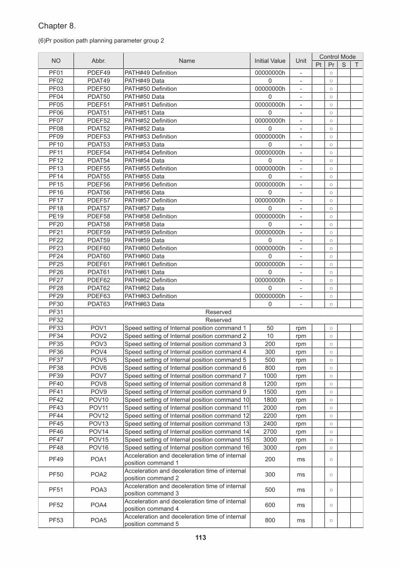
113
Chapter 8.
(6)Pr position path planning parameter group 2
NO Abbr. Name Initial Value Unit Control ModePt Pr S T
PF01 PDEF49 PATH#49 Definition 00000000h - ○PF02 PDAT49 PATH#49 Data 0 - ○PF03 PDEF50 PATH#50 Definition 00000000h - ○PF04 PDAT50 PATH#50 Data 0 - ○PF05 PDEF51 PATH#51 Definition 00000000h - ○PF06 PDAT51 PATH#51 Data 0 - ○PF07 PDEF52 PATH#52 Definition 00000000h - ○PF08 PDAT52 PATH#52 Data 0 - ○PF09 PDEF53 PATH#53 Definition 00000000h - ○PF10 PDAT53 PATH#53 Data 0 - ○PF11 PDEF54 PATH#54 Definition 00000000h - ○PF12 PDAT54 PATH#54 Data 0 - ○PF13 PDEF55 PATH#55 Definition 00000000h - ○PF14 PDAT55 PATH#55 Data 0 - ○PF15 PDEF56 PATH#56 Definition 00000000h - ○PF16 PDAT56 PATH#56 Data 0 - ○PF17 PDEF57 PATH#57 Definition 00000000h - ○PF18 PDAT57 PATH#57 Data 0 - ○PE19 PDEF58 PATH#58 Definition 00000000h - ○PF20 PDAT58 PATH#58 Data 0 - ○PF21 PDEF59 PATH#59 Definition 00000000h - ○PF22 PDAT59 PATH#59 Data 0 - ○PF23 PDEF60 PATH#60 Definition 00000000h - ○PF24 PDAT60 PATH#60 Data 0 - ○PF25 PDEF61 PATH#61 Definition 00000000h - ○PF26 PDAT61 PATH#61 Data 0 - ○PF27 PDEF62 PATH#62 Definition 00000000h - ○PF28 PDAT62 PATH#62 Data 0 - ○PF29 PDEF63 PATH#63 Definition 00000000h - ○PF30 PDAT63 PATH#63 Data 0 - ○PF31 ReservedPF32 ReservedPF33 POV1 Speed setting of Internal position command 1 50 rpm ○PF34 POV2 Speed setting of Internal position command 2 10 rpm ○PF35 POV3 Speed setting of Internal position command 3 200 rpm ○PF36 POV4 Speed setting of Internal position command 4 300 rpm ○PF37 POV5 Speed setting of Internal position command 5 500 rpm ○PF38 POV6 Speed setting of Internal position command 6 800 rpm ○PF39 POV7 Speed setting of Internal position command 7 1000 rpm ○PF40 POV8 Speed setting of Internal position command 8 1200 rpm ○PF41 POV9 Speed setting of Internal position command 9 1500 rpm ○PF42 POV10 Speed setting of Internal position command 10 1800 rpm ○PF43 POV11 Speed setting of Internal position command 11 2000 rpm ○PF44 POV12 Speed setting of Internal position command 12 2200 rpm ○PF45 POV13 Speed setting of Internal position command 13 2400 rpm ○PF46 POV14 Speed setting of Internal position command 14 2700 rpm ○PF47 POV15 Speed setting of Internal position command 15 3000 rpm ○PF48 POV16 Speed setting of Internal position command 16 3000 rpm ○
PF49 POA1 Acceleration and deceleration time of internal position command 1 200 ms ○
PF50 POA2 Acceleration and deceleration time of internal position command 2 300 ms ○
PF51 POA3 Acceleration and deceleration time of internal position command 3 500 ms ○
PF52 POA4 Acceleration and deceleration time of internal position command 4 600 ms ○
PF53 POA5 Acceleration and deceleration time of internal position command 5 800 ms ○
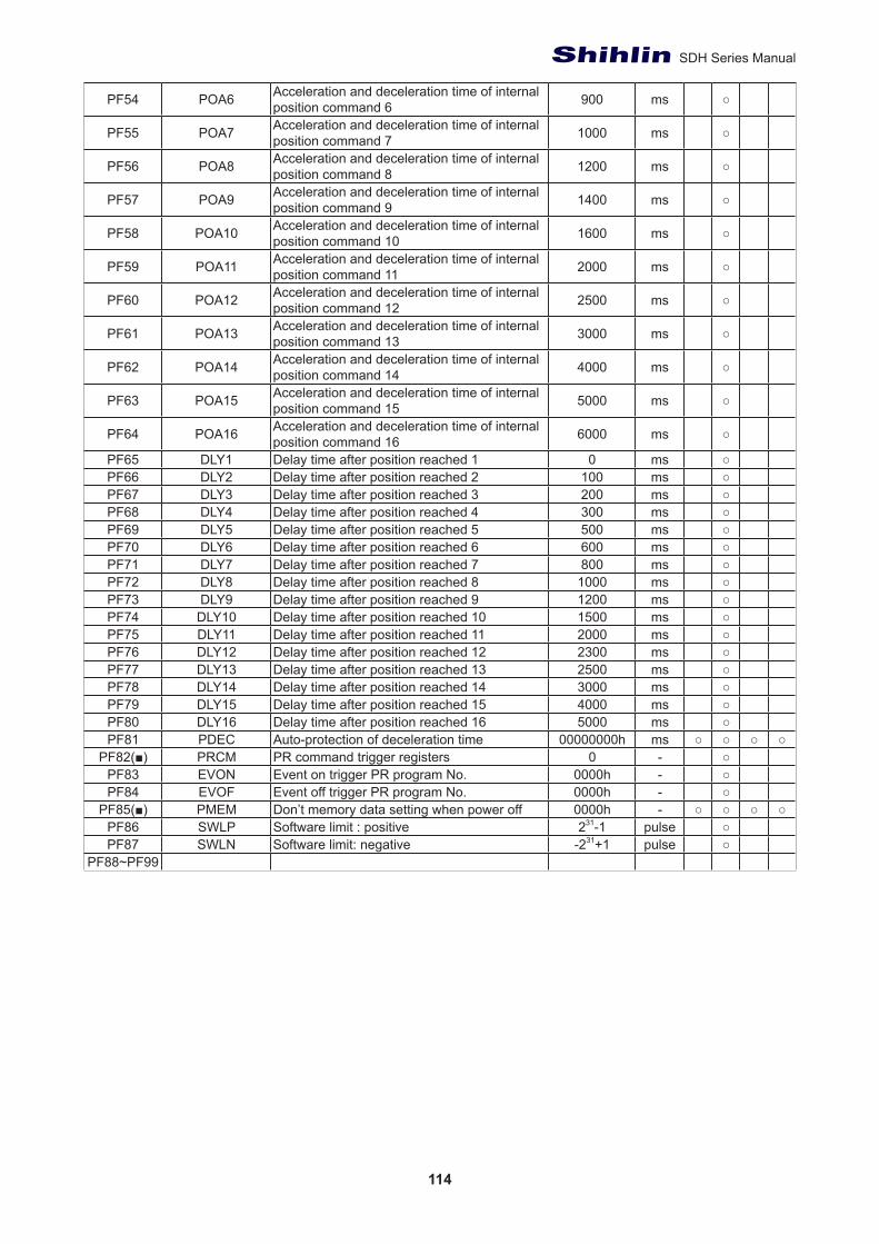
114
SDH Series Manual
PF54 POA6 Acceleration and deceleration time of internal position command 6 900 ms ○
PF55 POA7 Acceleration and deceleration time of internal position command 7 1000 ms ○
PF56 POA8 Acceleration and deceleration time of internal position command 8 1200 ms ○
PF57 POA9 Acceleration and deceleration time of internal position command 9 1400 ms ○
PF58 POA10 Acceleration and deceleration time of internal position command 10 1600 ms ○
PF59 POA11 Acceleration and deceleration time of internal position command 11 2000 ms ○
PF60 POA12 Acceleration and deceleration time of internal position command 12 2500 ms ○
PF61 POA13 Acceleration and deceleration time of internal position command 13 3000 ms ○
PF62 POA14 Acceleration and deceleration time of internal position command 14 4000 ms ○
PF63 POA15 Acceleration and deceleration time of internal position command 15 5000 ms ○
PF64 POA16 Acceleration and deceleration time of internal position command 16 6000 ms ○
PF65 DLY1 Delay time after position reached 1 0 ms ○PF66 DLY2 Delay time after position reached 2 100 ms ○PF67 DLY3 Delay time after position reached 3 200 ms ○PF68 DLY4 Delay time after position reached 4 300 ms ○PF69 DLY5 Delay time after position reached 5 500 ms ○PF70 DLY6 Delay time after position reached 6 600 ms ○PF71 DLY7 Delay time after position reached 7 800 ms ○PF72 DLY8 Delay time after position reached 8 1000 ms ○PF73 DLY9 Delay time after position reached 9 1200 ms ○PF74 DLY10 Delay time after position reached 10 1500 ms ○PF75 DLY11 Delay time after position reached 11 2000 ms ○PF76 DLY12 Delay time after position reached 12 2300 ms ○PF77 DLY13 Delay time after position reached 13 2500 ms ○PF78 DLY14 Delay time after position reached 14 3000 ms ○PF79 DLY15 Delay time after position reached 15 4000 ms ○PF80 DLY16 Delay time after position reached 16 5000 ms ○PF81 PDEC Auto-protection of deceleration time 00000000h ms ○ ○ ○ ○
PF82(■) PRCM PR command trigger registers 0 - ○PF83 EVON Event on trigger PR program No. 0000h - ○PF84 EVOF Event off trigger PR program No. 0000h - ○
PF85(■) PMEM Don’t memory data setting when power off 0000h - ○ ○ ○ ○PF86 SWLP Software limit : positive 231-1 pulse ○PF87 SWLN Software limit: negative -231+1 pulse ○
PF88~PF99
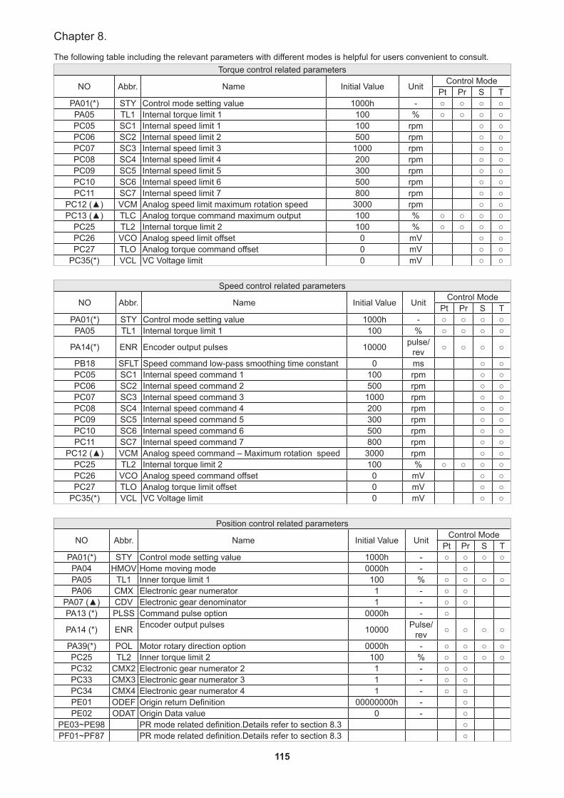
115
Chapter 8.
The following table including the relevant parameters with different modes is helpful for users convenient to consult.Torque control related parameters
NO Abbr. Name Initial Value Unit Control ModePt Pr S T
PA01(*) STY Control mode setting value 1000h - ○ ○ ○ ○PA05 TL1 Internal torque limit 1 100 % ○ ○ ○ ○PC05 SC1 Internal speed limit 1 100 rpm ○ ○PC06 SC2 Internal speed limit 2 500 rpm ○ ○PC07 SC3 Internal speed limit 3 1000 rpm ○ ○PC08 SC4 Internal speed limit 4 200 rpm ○ ○PC09 SC5 Internal speed limit 5 300 rpm ○ ○PC10 SC6 Internal speed limit 6 500 rpm ○ ○PC11 SC7 Internal speed limit 7 800 rpm ○ ○
PC12 (▲) VCM Analog speed limit maximum rotation speed 3000 rpm ○ ○PC13 (▲) TLC Analog torque command maximum output 100 % ○ ○ ○ ○
PC25 TL2 Internal torque limit 2 100 % ○ ○ ○ ○PC26 VCO Analog speed limit offset 0 mV ○ ○PC27 TLO Analog torque command offset 0 mV ○ ○
PC35(*) VCL VC Voltage limit 0 mV ○ ○
Speed control related parameters
NO Abbr. Name Initial Value Unit Control ModePt Pr S T
PA01(*) STY Control mode setting value 1000h - ○ ○ ○ ○PA05 TL1 Internal torque limit 1 100 % ○ ○ ○ ○
PA14(*) ENR Encoder output pulses 10000 pulse/rev ○ ○ ○ ○
PB18 SFLT Speed command low-pass smoothing time constant 0 ms ○ ○PC05 SC1 Internal speed command 1 100 rpm ○ ○PC06 SC2 Internal speed command 2 500 rpm ○ ○PC07 SC3 Internal speed command 3 1000 rpm ○ ○PC08 SC4 Internal speed command 4 200 rpm ○ ○PC09 SC5 Internal speed command 5 300 rpm ○ ○PC10 SC6 Internal speed command 6 500 rpm ○ ○PC11 SC7 Internal speed command 7 800 rpm ○ ○
PC12 (▲) VCM Analog speed command – Maximum rotation speed 3000 rpm ○ ○PC25 TL2 Internal torque limit 2 100 % ○ ○ ○ ○PC26 VCO Analog speed command offset 0 mV ○ ○PC27 TLO Analog torque limit offset 0 mV ○ ○
PC35(*) VCL VC Voltage limit 0 mV ○ ○
Position control related parameters
NO Abbr. Name Initial Value Unit Control ModePt Pr S T
PA01(*) STY Control mode setting value 1000h - ○ ○ ○ ○PA04 HMOV Home moving mode 0000h - ○PA05 TL1 Inner torque limit 1 100 % ○ ○ ○ ○PA06 CMX Electronic gear numerator 1 - ○ ○
PA07 (▲) CDV Electronic gear denominator 1 - ○ ○PA13 (*) PLSS Command pulse option 0000h - ○
PA14 (*) ENR Encoder output pulses 10000 Pulse/rev ○ ○ ○ ○
PA39(*) POL Motor rotary direction option 0000h - ○ ○ ○ ○PC25 TL2 Inner torque limit 2 100 % ○ ○ ○ ○PC32 CMX2 Electronic gear numerator 2 1 - ○ ○PC33 CMX3 Electronic gear numerator 3 1 - ○ ○PC34 CMX4 Electronic gear numerator 4 1 - ○ ○PE01 ODEF Origin return Definition 00000000h - ○PE02 ODAT Origin Data value 0 - ○
PE03~PE98 PR mode related definition.Details refer to section 8.3 ○PF01~PF87 PR mode related definition.Details refer to section 8.3 ○
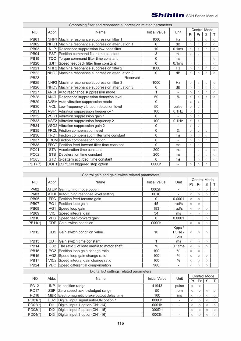
116
SDH Series Manual
Smoothing filter and resonance suppression related parameters
NO Abbr. Name Initial Value Unit Control ModePt Pr S T
PB01 NHF1 Machine resonance suppression filter 1 1000 Hz ○ ○ ○ ○PB02 NHD1 Machine resonance suppression attenuation 1 0 dB ○ ○ ○ ○PB03 NLP Resonance suppression low-pass filter 10 0.1ms ○ ○ ○ ○PB04 PST Position command filter time constant 3 ms ○ ○PB19 TQC Torque command filter time constant 0 ms ○PB20 SJIT Speed feedback filter time constant 0 0.1ms ○ ○ ○ ○PB21 NHF2 Machine resonance suppression filter 2 1000 Hz ○ ○ ○ ○PB22 NHD2 Machine resonance suppression attenuation 2 0 dB ○ ○ ○ ○PB23 ReservedPB25 NHF3 Machine resonance suppression filter 3 1000 Hz ○ ○ ○ ○PB26 NHD3 Machine resonance suppression attenuation 3 0 dB ○ ○ ○ ○PB27 ANCF Auto resonance suppression mode 1 - ○ ○ ○ ○PB28 ANCL Resonance suppression detection level 50 % ○ ○ ○ ○PB29 AVSM Auto vibration suppression mode 0 - ○ ○PB30 VCL Low-frequency vibration detection level 50 pulse ○ ○PB31 VSF1 Vibration suppression frequency 1 100 0.1Hz ○ ○PB32 VSG1 Vibration suppression gain 1 0 - ○ ○PB33 VSF2 Vibration suppression frequency 2 100 0.1Hz ○ ○PB34 VSG2 Vibration suppression gain 2 0 - ○ ○PB35 FRCL Friction compensation level 0 % ○ ○ ○PB36 FRCT Friction compensation filter time constant 0 ms ○ ○ ○PB37 FRCM Friction compensation option 0 - ○ ○ ○PB38 FFCT Position feed forward filter time constant 0 ms ○ ○PC01 STA Acceleration time constant 200 ms ○ ○ ○PC02 STB Deceleration time constant 200 ms ○ ○ ○PC03 STC S-pattern acc./dec. time constant 0 ms ○ ○ ○
PD17(*) DOP1 LSP/LSN triggered stop option 0000h - ○ ○ ○
Control gain and gain switch related parameters
NO Abbr. Name Initial Value Unit Control ModePt Pr S T
PA02 ATUM Gain tuning mode option 0002h - ○ ○ ○ ○PA03 ATUL Auto-tuning response level setting 0010 - ○ ○ ○ ○PB05 FFC Position feed-forward gain 0 0.0001 ○ ○PB07 PG1 Position loop gain 45 rad/s ○ ○PB08 VG1 Speed loop gain 183 rad/s ○ ○ ○PB09 VIC Speed integral gain 34 ms ○ ○ ○PB10 VFG Speed feed-forward gain 0 0.0001 ○
PB11(*) CDP Gain switch condition 0000h - ○ ○ ○
PB12 CDS Gain switch condition value 10Kpps /Pulse /
rpm○ ○ ○
PB13 CDT Gain switch time constant 1 ms ○ ○ ○PB14 GD2 The ratio 2 of load inertia to motor shaft 70 0.1time ○ ○ ○PB15 PG2 Position loop gain change ratio 100 % ○ ○PB16 VG2 Speed loop gain change ratio 100 % ○ ○ ○PB17 VIC2 Speed integral gain change ratio 100 % ○ ○ ○PB24 VDC Speed differential compensation 980 - ○ ○ ○
Digital I/O settings related parameters
NO Abbr. Name Initial Value Unit Control ModePt Pr S T
PA12 INP In-position range 41943 pulse ○ ○PC17 ZSP Zero speed acknowledged range 50 rpm ○ ○ ○ ○PC16 MBR Electromagnetic brake output delay time 100 ms ○ ○ ○ ○
PD01(*) DIA1 Digital input signal auto-ON option 1 0000h - ○ ○ ○ ○PD02(*) DI1 Digital input 1 option(CN1-14) 0001h - ○ ○ ○ ○PD03(*) DI2 Digital input 2 option(CN1-15) 000Dh - ○ ○ ○ ○PD04(*) DI3 Digital input 3 option(CN1-16) 0003h - ○ ○ ○ ○
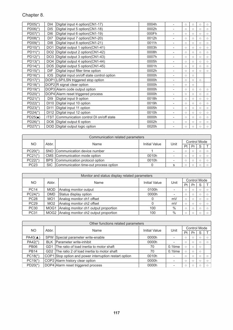
117
Chapter 8.
PD05(*) DI4 Digital input 4 option(CN1-17) 0004h - ○ ○ ○ ○PD06(*) DI5 Digital input 5 option(CN1-18) 0002h - ○ ○ ○ ○PD07(*) DI6 Digital input 6 option(CN1-19) 000Fh - ○ ○ ○ ○PD08(*) DI7 Digital input 7 option(CN1-20) 0012h - ○ ○ ○ ○PD09(*) DI8 Digital input 8 option(CN1-21) 0011h - ○ ○ ○ ○PD10(*) DO1 Digital output 1 option(CN1-41) 0003h - ○ ○ ○ ○PD11(*) DO2 Digital output 2 option(CN1-42) 0008h - ○ ○ ○ ○PD12(*) DO3 Digital output 3 option(CN1-43) 0007h - ○ ○ ○ ○PD13(*) DO4 Digital output 4 option(CN1-44) 0005h - ○ ○ ○ ○PD14(*) DO5 Digital output 5 option(CN1-45) 0001h - ○ ○ ○ ○PD15(*) DIF Digital input filter time option 0002h - ○ ○ ○ ○PD16(*) IOS Digital input on/off state control option 0000h - ○ ○PD17(*) DOP1 LSP/LSN triggered stop option 0000h - ○ ○ ○PD18(*) DOP2 R signal clear option 0000h - ○ ○PD19(*) DOP3 Alarm code output option 0000h - ○ ○ ○ ○PD20(*) DOP4 Alarm reset triggered process 0000h - ○ ○ ○ ○PD21(*) DI9 Digital input 9 option 0018h - ○ ○ ○ ○PD22(*) DI10 Digital input 10 option 0019h - ○ ○ ○ ○PD23(*) DI11 Digital input 11 option 0005h - ○ ○ ○ ○PD24(*) DI12 Digital input 12 option 0010h - ○ ○ ○ ○PD25(■) ITST Communication control DI on/off state 0000h - ○ ○ ○ ○PD26(*) DO6 Digital output 6 option 0002h - ○ ○ ○ ○PD27(*) DOD Digital output logic option 0020h - ○ ○ ○ ○
Communication related parameters
NO Abbr. Name Initial Value Unit Control ModePt Pr S T
PC20(*) SNO Communication device number 1 - ○ ○ ○ ○PC21(*) CMS Communication mode option 0010h - ○ ○ ○ ○PC22(*) BPS Communication protocol option 0010h - ○ ○ ○ ○PC23 SIC Communication time-out process option 0 s ○ ○ ○ ○
Monitor and status display related parameters
NO Abbr. Name Initial Value Unit Control ModePt Pr S T
PC14 MOD Analog monitor output 0100h - ○ ○ ○ ○PC24(*) DMD Status display option 0000h - ○ ○ ○ ○PC28 MO1 Analog monitor ch1 offset 0 mV ○ ○ ○ ○PC29 MO2 Analog monitor ch2 offset 0 mV ○ ○ ○ ○PC30 MOG1 Analog monitor ch1 output proportion 100 % ○ ○ ○ ○PC31 MOG2 Analog monitor ch2 output proportion 100 % ○ ○ ○ ○
Other functions related parameters
NO Abbr. Name Initial Value Unit Control ModePt Pr S T
PA40(▲) SPW Special parameter write-enable 0000h - ○ ○ ○ ○PA42(*) BLK Parameter write-inhibit 0000h - ○ ○ ○ ○PB06 GD1 The ratio of load inertia to motor shaft 70 0.1time ○ ○ ○PB14 GD2 The ratio 2 of load inertia to motor shaft 70 0.1time ○ ○ ○
PC18(*) COP1 Stop option and power interruption restart option 0010h - ○ ○ ○ ○PC19(*) COP2 Alarm history clear option 0000h - ○ ○ ○ ○PD20(*) DOP4 Alarm reset triggered process 0000h - ○ ○ ○ ○
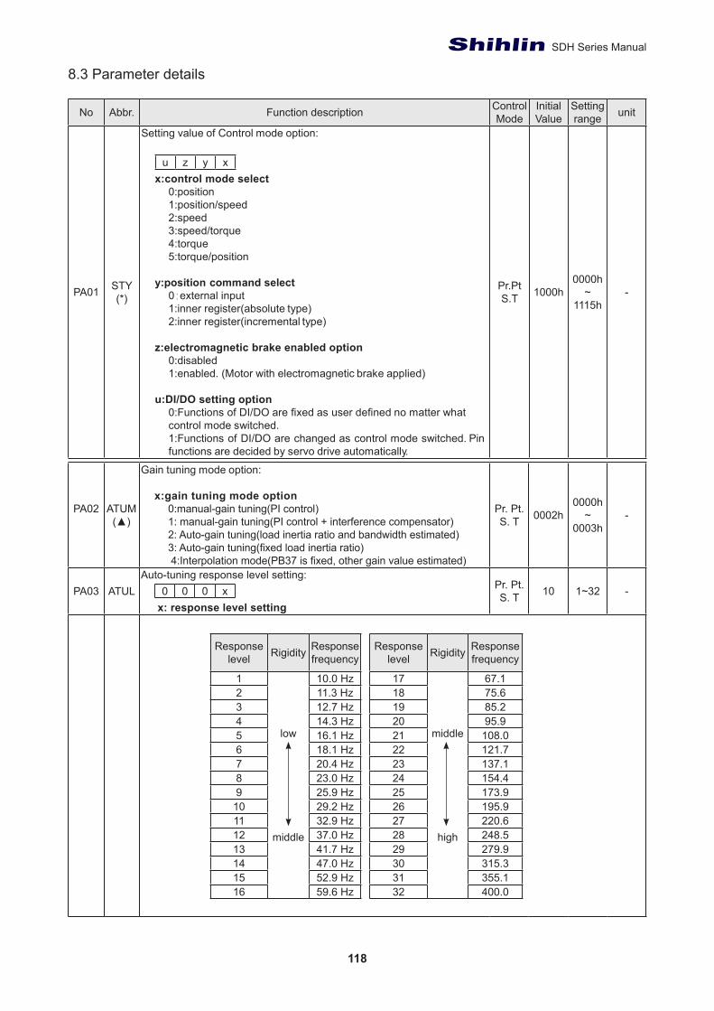
118
SDH Series Manual
8.3 Parameter details
No Abbr. Function description Control Mode
Initial Value
Setting range unit
PA01 STY(*)
Setting value of Control mode option:
u z y xx:control mode select
0:position1:position/speed2:speed3:speed/torque4:torque5:torque/position
y:position command select0:external input1:inner register(absolute type)2:inner register(incremental type)
z:electromagnetic brake enabled option0:disabled1:enabled. (Motor with electromagnetic brake applied)
u:DI/DO setting option0:Functions of DI/DO are fixed as user defined no matter what control mode switched.1:Functions of DI/DO are changed as control mode switched. Pin functions are decided by servo drive automatically.
Pr.PtS.T 1000h
0000h~
1115h-
PA02 ATUM(▲)
Gain tuning mode option:
x:gain tuning mode option0:manual-gain tuning(PI control)1: manual-gain tuning(PI control + interference compensator)2: Auto-gain tuning(load inertia ratio and bandwidth estimated)3: Auto-gain tuning(fixed load inertia ratio) 4:Interpolation mode(PB37 is fixed, other gain value estimated)
Pr. Pt.S. T 0002h
0000h~
0003h-
PA03 ATULAuto-tuning response level setting:
0 0 0 x x: response level setting
Pr. Pt.S. T 10 1~32 -
Response level Rigidity Response
frequency
1
low
middle
10.0 Hz2 11.3 Hz3 12.7 Hz4 14.3 Hz5 16.1 Hz6 18.1 Hz7 20.4 Hz8 23.0 Hz9 25.9 Hz10 29.2 Hz11 32.9 Hz12 37.0 Hz13 41.7 Hz14 47.0 Hz15 52.9 Hz16 59.6 Hz
Response level Rigidity Response
frequency
17
middle
high
67.118 75.619 85.220 95.921 108.022 121.723 137.124 154.425 173.926 195.927 220.628 248.529 279.930 315.331 355.132 400.0
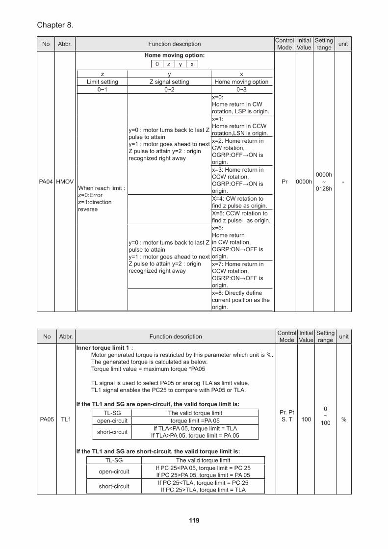
119
Chapter 8.
No Abbr. Function description Control Mode
Initial Value
Setting range unit
PA04 HMOV
Home moving option:0 z y x
z y xLimit setting Z signal setting Home moving option
0~1 0~2 0~8
When reach limit :z=0:Errorz=1:direction reverse
y=0 : motor turns back to last Z pulse to attainy=1 : motor goes ahead to next Z pulse to attain y=2 : origin recognized right away
x=0:Home return in CW rotation, LSP is origin.x=1:Home return in CCW rotation,LSN is origin.x=2: Home return in CW rotation,OGRP:OFF→ON is origin.x=3: Home return in CCW rotation,OGRP:OFF→ON is origin.X=4: CW rotation to find z pulse as origin.X=5: CCW rotation to find z pulse as origin.
y=0 : motor turns back to last Z pulse to attainy=1 : motor goes ahead to next Z pulse to attain y=2 : origin recognized right away
x=6:Home return in CW rotation, OGRP:ON→OFF is origin.x=7: Home return in CCW rotation,OGRP:ON→OFF is origin.x=8: Directly define current position as the origin.
Pr 0000h0000h
~0128h
-
No Abbr. Function description Control Mode
Initial Value
Setting range unit
PA05 TL1
Inner torque limit 1:Motor generated torque is restricted by this parameter which unit is %. The generated torque is calculated as below.Torque limit value = maximum torque *PA05
TL signal is used to select PA05 or analog TLA as limit value.TL1 signal enables the PC25 to compare with PA05 or TLA.
If the TL1 and SG are open-circuit, the valid torque limit is:TL-SG The valid torque limit
open-circuit torque limit =PA 05
short-circuit If TLA<PA 05, torque limit = TLAIf TLA>PA 05, torque limit = PA 05
If the TL1 and SG are short-circuit, the valid torque limit is:TL-SG The valid torque limit
open-circuit If PC 25<PA 05, torque limit = PC 25If PC 25>PA 05, torque limit = PA 05
short-circuit If PC 25<TLA, torque limit = PC 25If PC 25>TLA, torque limit = TLA
Pr. PtS. T 100
0~
100 %
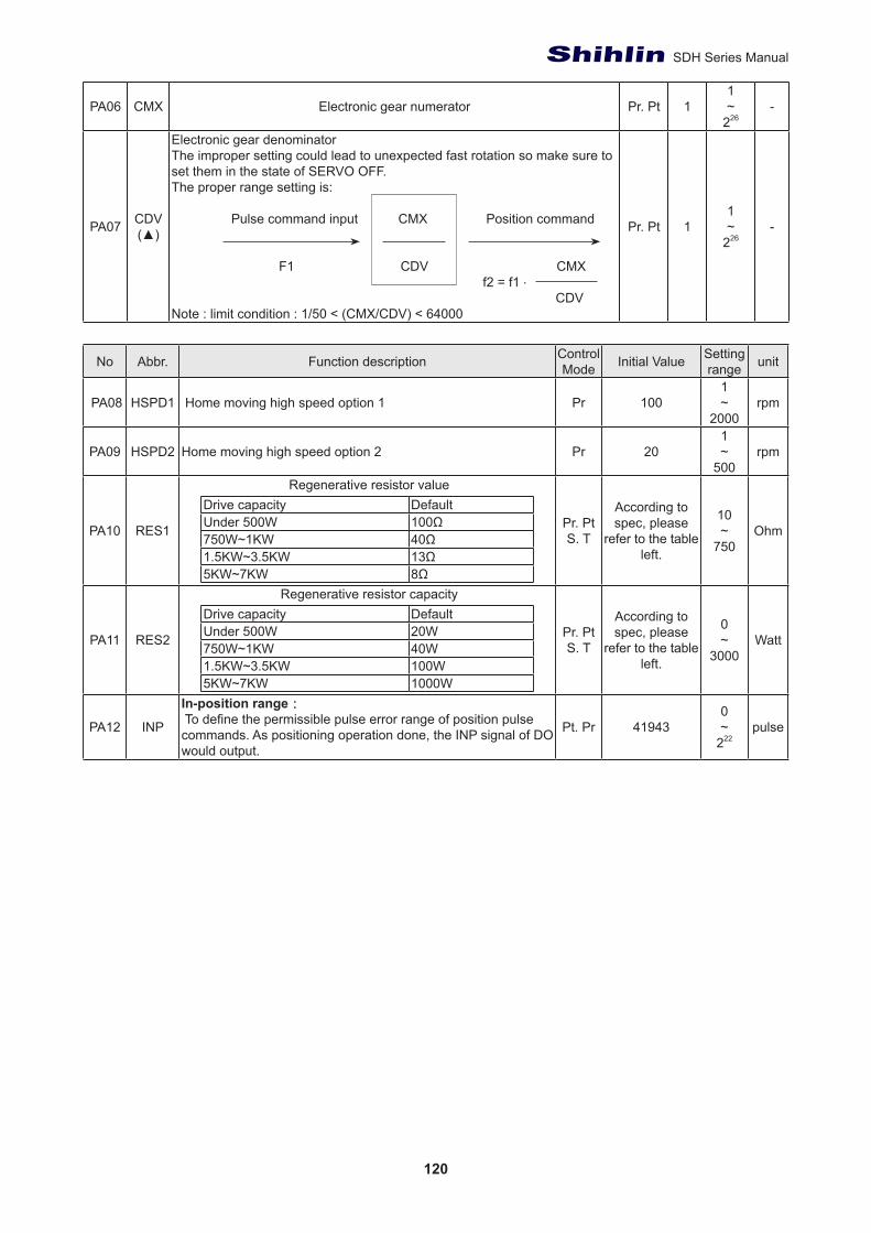
120
SDH Series Manual
PA06 CMX Electronic gear numerator Pr. Pt 11~
226-
PA07 CDV(▲)
Electronic gear denominatorThe improper setting could lead to unexpected fast rotation so make sure to set them in the state of SERVO OFF. The proper range setting is:
Pulse command input CMX Position command
F1 CDV CMXf2 = f1 ‧
CDV Note : limit condition : 1/50 < (CMX/CDV) < 64000
Pr. Pt 11~
226-
No Abbr. Function description Control Mode Initial Value Setting
range unit
PA08 HSPD1 Home moving high speed option 1 Pr 1001~
2000rpm
PA09 HSPD2 Home moving high speed option 2 Pr 201~
500rpm
PA10 RES1
Regenerative resistor valueDrive capacity DefaultUnder 500W 100Ω750W~1KW 40Ω1.5KW~3.5KW 13Ω5KW~7KW 8Ω
Pr. PtS. T
According to spec, please
refer to the table left.
10~
750Ohm
PA11 RES2
Regenerative resistor capacityDrive capacity DefaultUnder 500W 20W750W~1KW 40W1.5KW~3.5KW 100W5KW~7KW 1000W
Pr. PtS. T
According to spec, please
refer to the table left.
0~
3000Watt
PA12 INP
In-position range: To define the permissible pulse error range of position pulse commands. As positioning operation done, the INP signal of DO would output.
Pt. Pr 419430~
222pulse
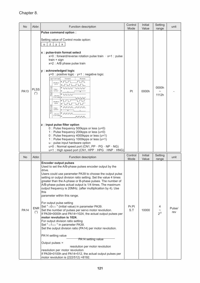
121
Chapter 8.
No Abbr. Function description Control Mode
Initial Value
Setting range unit
PA13 PLSS(*)
Pulse command option:
Setting value of Control mode option:u z y x
x:pulse-train format selectx=0:forward/reverse rotation pulse train ,x=1:pulse train + signx=2:A/B phase pulse train
y:acknowledged logicy=0:positive logic,y=1:negative logic
z:input pulse filter option0:Pulse frequency 500kpps or less (u=0)1:Pulse frequency 200kpps or less (u=0)0:Pulse frequency 4000kpps or less (u=1)1:Pulse frequency 1000kpps or less (u=1)u:pulse input hardware optionu=0:Normal speed port (CN1, PP、PG、NP、NG) u=1:High speed port (CN1, HPP、HPG、HNP、HNG)
Pt 0000h0000h
~1112h
-
No Abbr. Function description Control Mode
Initial Value
Setting range unit
PA14 ENR(*)
Encoder output pulsesUsed to set the A/B-phase pulses encoder output by the drive.Users could use parameter PA39 to choose the output pulsesetting or output division ratio setting. Set the value 4 timesgreater than the A-phase or B-phase pulses. The number ofA/B-phase pulses actual output is 1/4 times. The maximumoutput frequency is 20MHz. (after multiplication by 4). Use thisparameter within this range.
For output pulse settingSet " □0□□ " (initial value) in parameter PA39.Set the number of pulses per servo motor revolution.If PA39=0000h and PA14=1024, the actual output pulses permotor revolution is 1024. For output division ratio settingSet " □1□□ " in parameter PA39.Set the output division ratio (PA14) per motor revolution.
PA14 setting value PA14 setting value
Output pulses =resolution per motor revolution
resolution per motor revolutionIf PA39=0100h and PA14=512, the actual output pulses permotor revolution is (222/512) =8192.
Pr.PtS.T 10000
4~
222
Pulse/rev
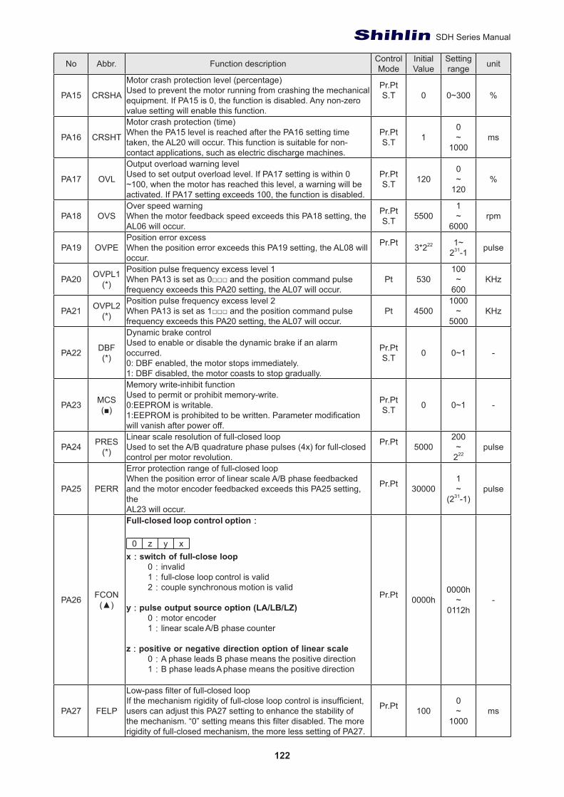
122
SDH Series Manual
No Abbr. Function description Control Mode
Initial Value
Setting range unit
PA15 CRSHA
Motor crash protection level (percentage)Used to prevent the motor running from crashing the mechanical equipment. If PA15 is 0, the function is disabled. Any non-zero value setting will enable this function.
Pr.PtS.T 0 0~300 %
PA16 CRSHT
Motor crash protection (time)When the PA15 level is reached after the PA16 setting time taken, the AL20 will occur. This function is suitable for non-contact applications, such as electric discharge machines.
Pr.PtS.T 1
0~
1000ms
PA17 OVL
Output overload warning levelUsed to set output overload level. If PA17 setting is within 0 ~100, when the motor has reached this level, a warning will be activated. If PA17 setting exceeds 100, the function is disabled.
Pr.PtS.T 120
0~
120%
PA18 OVSOver speed warningWhen the motor feedback speed exceeds this PA18 setting, the AL06 will occur.
Pr.PtS.T 5500
1~
6000rpm
PA19 OVPEPosition error excessWhen the position error exceeds this PA19 setting, the AL08 will occur.
Pr.Pt 3*222 1~231-1 pulse
PA20 OVPL1(*)
Position pulse frequency excess level 1When PA13 is set as 0□□□ and the position command pulse frequency exceeds this PA20 setting, the AL07 will occur.
Pt 530100~
600KHz
PA21 OVPL2(*)
Position pulse frequency excess level 2When PA13 is set as 1□□□ and the position command pulsefrequency exceeds this PA20 setting, the AL07 will occur.
Pt 45001000
~5000
KHz
PA22 DBF(*)
Dynamic brake controlUsed to enable or disable the dynamic brake if an alarm occurred.0: DBF enabled, the motor stops immediately.1: DBF disabled, the motor coasts to stop gradually.
Pr.PtS.T 0 0~1 -
PA23 MCS(■)
Memory write-inhibit functionUsed to permit or prohibit memory-write.0:EEPROM is writable.1:EEPROM is prohibited to be written. Parameter modificationwill vanish after power off.
Pr.PtS.T 0 0~1 -
PA24 PRES(*)
Linear scale resolution of full-closed loopUsed to set the A/B quadrature phase pulses (4x) for full-closedcontrol per motor revolution.
Pr.Pt 5000200~
222pulse
PA25 PERR
Error protection range of full-closed loopWhen the position error of linear scale A/B phase feedbacked and the motor encoder feedbacked exceeds this PA25 setting, theAL23 will occur.
Pr.Pt 300001~
(231-1)pulse
PA26 FCON(▲)
Full-closed loop control option:
0 z y xx:switch of full-close loop
0:invalid1:full-close loop control is valid2:couple synchronous motion is valid
y:pulse output source option (LA/LB/LZ)0:motor encoder1:linear scale A/B phase counter
z:positive or negative direction option of linear scale0:A phase leads B phase means the positive direction1:B phase leads A phase means the positive direction
Pr.Pt 0000h0000h
~0112h
-
PA27 FELP
Low-pass filter of full-closed loopIf the mechanism rigidity of full-close loop control is insufficient, users can adjust this PA27 setting to enhance the stability of the mechanism. “0” setting means this filter disabled. The more rigidity of full-closed mechanism, the more less setting of PA27.
Pr.Pt 1000~
1000ms
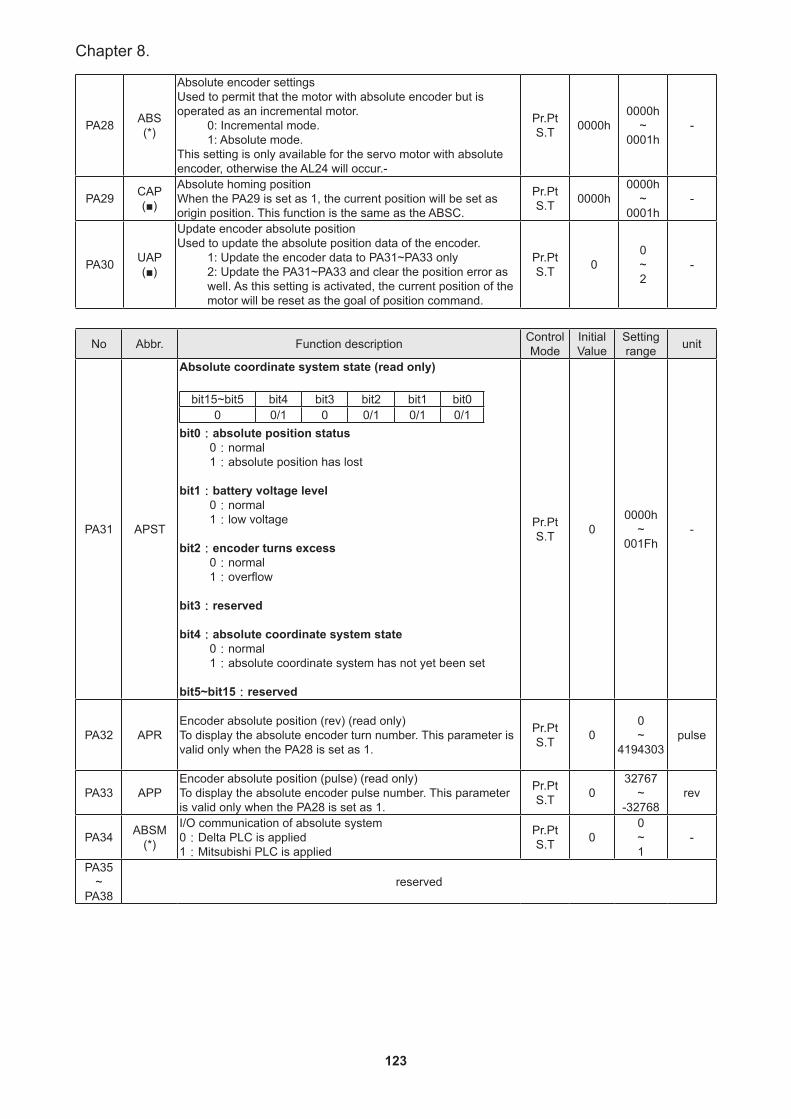
123
Chapter 8.
PA28 ABS(*)
Absolute encoder settingsUsed to permit that the motor with absolute encoder but isoperated as an incremental motor.
0: Incremental mode.1: Absolute mode.
This setting is only available for the servo motor with absoluteencoder, otherwise the AL24 will occur.-
Pr.PtS.T 0000h
0000h~
0001h-
PA29 CAP(■)
Absolute homing positionWhen the PA29 is set as 1, the current position will be set asorigin position. This function is the same as the ABSC.
Pr.PtS.T 0000h
0000h~
0001h-
PA30 UAP(■)
Update encoder absolute positionUsed to update the absolute position data of the encoder.
1: Update the encoder data to PA31~PA33 only2: Update the PA31~PA33 and clear the position error as well. As this setting is activated, the current position of the motor will be reset as the goal of position command.
Pr.PtS.T 0
0~2
-
No Abbr. Function description Control Mode
Initial Value
Setting range unit
PA31 APST
Absolute coordinate system state (read only)
bit15~bit5 bit4 bit3 bit2 bit1 bit00 0/1 0 0/1 0/1 0/1
bit0:absolute position status0:normal1:absolute position has lost
bit1:battery voltage level0:normal1:low voltage
bit2:encoder turns excess0:normal1:overflow
bit3:reserved
bit4:absolute coordinate system state0:normal1:absolute coordinate system has not yet been set
bit5~bit15:reserved
Pr.PtS.T 0
0000h~
001Fh-
PA32 APREncoder absolute position (rev) (read only)To display the absolute encoder turn number. This parameter is valid only when the PA28 is set as 1.
Pr.PtS.T 0
0~
4194303pulse
PA33 APPEncoder absolute position (pulse) (read only)To display the absolute encoder pulse number. This parameter is valid only when the PA28 is set as 1.
Pr.PtS.T 0
32767~
-32768rev
PA34 ABSM(*)
I/O communication of absolute system0:Delta PLC is applied1:Mitsubishi PLC is applied
Pr.PtS.T 0
0~1
-
PA35~
PA38reserved
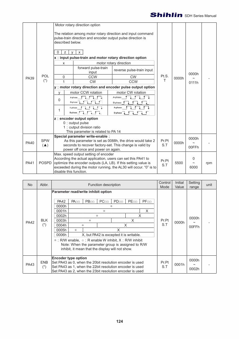
124
SDH Series Manual
PA39 POL(*)
Motor rotary direction option
The relation among motor rotary direction and input commandpulse-train direction and encoder output pulse direction isdescribed below.
0 z y xx:input pulse-train and motor rotary direction option
x motor rotary directionforward pulse-train
input reverse pulse-train input
0 CCW CW1 CW CCW
y:motor rotary direction and encoder pulse output optiony motor CCW rotation motor CW rotation
0
1
z:encoder output option0:output pulse1:output division ratio This parameter is related to PA 14
Pt.S.T 0000h
0000h~
0111h-
PA40 SPW(▲)
Special parameter write-enable: As this parameter is set as 0088h, the drive would take 2seconds to recover factory-set. This change is valid by power off once and power on again.
Pr.PtS.T 0000h
0000h~
00FFh-
PA41 POSPD
Max. speed output setting of encoderAccording the actual application, users can set this PA41 to optimize the encoder outputs (LA, LB). If this setting value is exceeded during the motor running, the AL30 will occur. “0” is to disable this function.
Pr.PtS.T 5500
0~
6000rpm
No Abbr. Function description Control Mode
Initial Value
Setting range unit
PA42 BLK(*)
Parameter read/write inhibit option
PA42 PA□□ PB□□ PC□□ PD□□ PE□□ PF□□0000h ◎0001h ◎ X0002h ◎ X0003h ◎ X0004h ◎ X0005h ◎ X0006h X, but PA42 is excepted it is writable.
◎:R/W enable, ○:R enable W inhibit, X:R/W inhibitNote: When the parameter group is assigned to R/W inhibit, it mean that the display will not show.
Pr.PtS.T 0000h
0000h~
00FFh-
PA43 ENB(*)
Encoder type optionSet PA43 as 0, when the 20bit resolution encoder is usedSet PA43 as 1, when the 22bit resolution encoder is usedSet PA43 as 2, when the 23bit resolution encoder is used
Pr.PtS.T 0001h
0000h~
0002h-
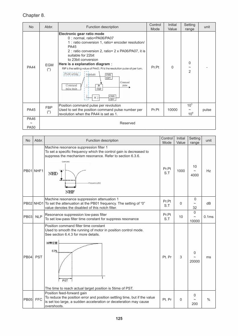
125
Chapter 8.
No Abbr. Function description Control Mode
Initial Value
Setting range unit
PA44 EGM(*)
Electronic gear ratio mode0:normal, ratio=PA06/PA071:ratio conversion 1, ratio= encoder resolution/PA452:ratio conversion 2, ratio= 2 x PA06/PA07, it is suitable for 22bitto 23bit conversion
Here is a explanation diagram:Pr.Pt 0
0~2
-
PA45 FBP(*)
Position command pulse per revolutionUsed to set the position command pulse number per revolution when the PA44 is set as 1.
Pr.Pt 10000103
~ 106
pulse
PA46~
PA50Reserved
No Abbr. Function description Control Mode
Initial Value
Setting range unit
PB01 NHF1
Machine resonance suppression filter 1To set a specific frequency which the control gain is decreased to suppress the mechanism resonance. Refer to section 6.3.6.
Pr.PtS.T 1000
10~
4000Hz
PB02 NHD1Machine resonance suppression attenuation 1To set the attenuation at the PB01 frequency. The setting of “0”value denotes the disabled of this notch filter.
Pr.PtS.T 0
0~32
dB
PB03 NLP Resonance suppression low-pass filterTo set low-pass filter time constant for suppress resonance
Pr.PtS.T 10
0~
100000.1ms
PB04 PST
Position command filter time constantUsed to smooth the running of motor in position control mode.See section 6.4.3 for more details.
The time to reach actual target position is 5time of PST.
Pt. Pr 30~
20000ms
PB05 FFC
Position feed-forward gainTo reduce the position error and position settling time, but if the value is set too large, a sudden acceleration or deceleration may cause overshoots.
Pt. Pr 00~
200%
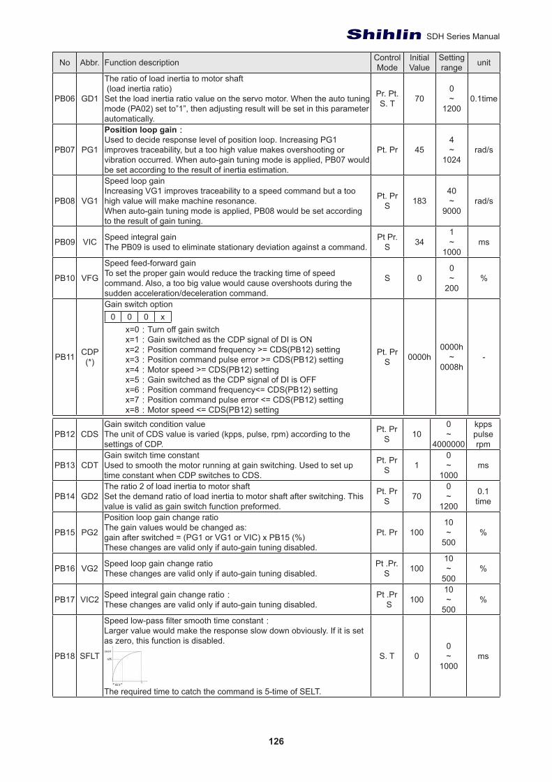
126
SDH Series Manual
No Abbr. Function description Control Mode
Initial Value
Setting range unit
PB06 GD1
The ratio of load inertia to motor shaft (load inertia ratio)Set the load inertia ratio value on the servo motor. When the auto tuning mode (PA02) set to”1”, then adjusting result will be set in this parameter automatically.
Pr. Pt.S. T 70
0~
12000.1time
PB07 PG1
Position loop gain: Used to decide response level of position loop. Increasing PG1 improves traceability, but a too high value makes overshooting or vibration occurred. When auto-gain tuning mode is applied, PB07 would be set according to the result of inertia estimation.
Pt. Pr 454~
1024rad/s
PB08 VG1
Speed loop gainIncreasing VG1 improves traceability to a speed command but a too high value will make machine resonance.When auto-gain tuning mode is applied, PB08 would be set according to the result of gain tuning.
Pt. PrS 183
40~
9000rad/s
PB09 VIC Speed integral gainThe PB09 is used to eliminate stationary deviation against a command.
Pt Pr.S 34
1~
1000ms
PB10 VFG
Speed feed-forward gainTo set the proper gain would reduce the tracking time of speed command. Also, a too big value would cause overshoots during the sudden acceleration/deceleration command.
S 00~
200%
PB11 CDP(*)
Gain switch option0 0 0 x
x=0:Turn off gain switchx=1:Gain switched as the CDP signal of DI is ONx=2:Position command frequency >= CDS(PB12) settingx=3:Position command pulse error >= CDS(PB12) setting x=4:Motor speed >= CDS(PB12) setting x=5:Gain switched as the CDP signal of DI is OFFx=6:Position command frequency<= CDS(PB12) setting x=7:Position command pulse error <= CDS(PB12) settingx=8:Motor speed <= CDS(PB12) setting
Pt. PrS 0000h
0000h~
0008h-
PB12 CDSGain switch condition valueThe unit of CDS value is varied (kpps, pulse, rpm) according to the settings of CDP.
Pt. PrS 10
0~
4000000
kppspulserpm
PB13 CDTGain switch time constantUsed to smooth the motor running at gain switching. Used to set up time constant when CDP switches to CDS.
Pt. PrS 1
0~
1000ms
PB14 GD2The ratio 2 of load inertia to motor shaftSet the demand ratio of load inertia to motor shaft after switching. This value is valid as gain switch function preformed.
Pt. PrS 70
0~
1200
0.1time
PB15 PG2
Position loop gain change ratioThe gain values would be changed as:gain after switched = (PG1 or VG1 or VIC) x PB15 (%)These changes are valid only if auto-gain tuning disabled.
Pt. Pr 10010~
500%
PB16 VG2 Speed loop gain change ratioThese changes are valid only if auto-gain tuning disabled.
Pt .Pr.S 100
10~
500%
PB17 VIC2 Speed integral gain change ratio:These changes are valid only if auto-gain tuning disabled.
Pt .Pr S 100
10~
500%
PB18 SFLT
Speed low-pass filter smooth time constant:Larger value would make the response slow down obviously. If it is set as zero, this function is disabled.
The required time to catch the command is 5-time of SELT.
S. T 00~
1000ms

127
Chapter 8.
No Abbr. Function description Control Mode
Initial Value
Setting range unit
PB19 TQC
Torque command filter time constant:Larger value would make the response slow down obviously. If it is set as zero, this function is disabled.
The required time to catch the command is 5-time of TQC.
T 00~
5000 ms
PB20 SJIT Speed feedback filter time constantUsed to set the filter time constant of motor speed feedback.
Pr.PtS.T 0
0~
10000.1ms
PB21 NHF2Machine resonance suppression filter 2:The secondary option of notch filter frequency to suppress the mechanism resonance.
Pr.PtS.T 1000
10~
4000Hz
PB22 NHD2 Machine resonance suppression attenuation 2:The secondary option of notch filter attenuation.0 is setting for turning off the function of Notch filter.
Pr.PtS.T 0
0~32
dB
PB23 Reserved
PB24 VDC Speed differential compensation:Used to set the Speed differential compensation. It is valid only if digital terminals input is “ON”.
Pr.PtS 980
0~
1000-
PB25 NHF3
Machine resonance suppression filter 3:The third option of notch filter frequency to suppress the mechanism resonance.
Pr.PtS.T 1000
10~
4000Hz
PB26 NHD3Machine resonance suppression attenuation 3:The third option of notch filter attenuation.0 is setting for turning off the function of Notch filter.
Pr.PtS.T 0
0~32
dB
PB27 ANCF
Auto-resonance suppression mode setting( for machine resonance suppression filter 1&2)
Setting value is 0:StableSetting value is 1:Stable after resonance suppressionSetting value is 2:Continuous resonance suppres sion
Pr.PtS.T 1
0~2
-
PB28 ANCLResonance suppression detection levelThe smaller the setting value is, the more sensitive theresonance will be.
Pr.PtS.T 50
1~
300%
PB29 AVSM
Auto low frequency resonance suppression mode setting:Setting value is 0:StableSetting value is 1:Stable after resonance suppressionDescription:
When it is set to 1: Auto resonance, the value returns to 0 automatically and saves the point of resonance suppression to PB31 (VSF1) when it is stable.
Pr.Pt 00~1
-
PB30 VCL
Low frequency resonance suppression detection levelWhen PB29 is set to 1, low frequency resonance suppression is on. The lower value of Low frequency resonance suppression detection level is, the more sensitive the detection will be, but misjudge the noise or other not main low frequency resonance easily. The higher the value is, the more correct the judge is. But if the machine resonance is too small, the lower value is hard to search for low-frequency resonance.
Pr.Pt 501~
8000pulse
PB31 VSF1Low-frequency vibration suppression 1The setting value of the first low-frequency vibration suppression.If PB32 is set to 0, then it will disable the first low-frequency filter.
Pr.Pt 1001~
30000.1Hz
PB32 VSG1
Low-frequency vibration suppression gain 1The bigger value it is, the better the position response will be. However, if the value is set too big, the motor will not be able to smoothly operate. It is suggested to set the value to 1
Pr.Pt 00~15
-
PB33 VSF2Low-frequency vibration suppression 2The setting value of the second low-frequency vibration suppression. If PB34 is set to 0, then it will disable the second low-frequency filter.
Pr.Pt 1001~
30000.1Hz
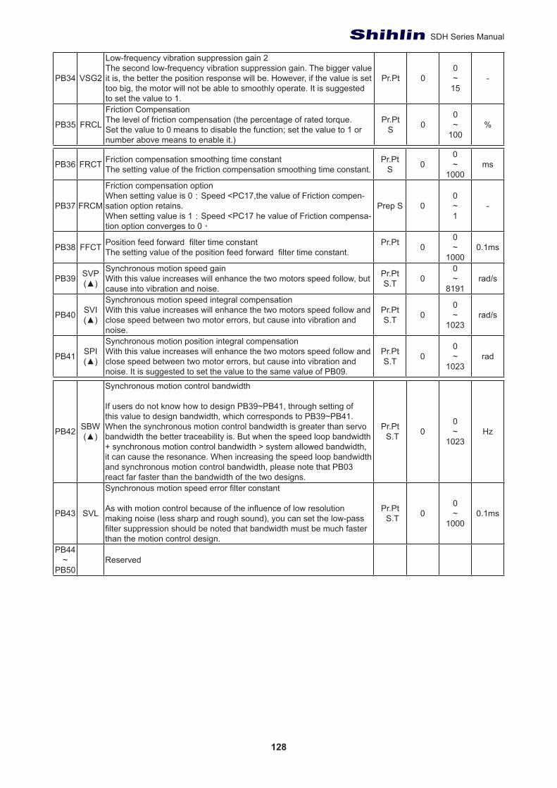
128
SDH Series Manual
PB34 VSG2
Low-frequency vibration suppression gain 2The second low-frequency vibration suppression gain. The bigger value it is, the better the position response will be. However, if the value is set too big, the motor will not be able to smoothly operate. It is suggested to set the value to 1.
Pr.Pt 00~15
-
PB35 FRCL
Friction CompensationThe level of friction compensation (the percentage of rated torque. Set the value to 0 means to disable the function; set the value to 1 or number above means to enable it.)
Pr.PtS 0
0~
100%
PB36 FRCT Friction compensation smoothing time constantThe setting value of the friction compensation smoothing time constant.
Pr.PtS 0
0~
1000ms
PB37 FRCM
Friction compensation optionWhen setting value is 0:Speed <PC17,the value of Friction compen-sation option retains.When setting value is 1:Speed <PC17 he value of Friction compensa-tion option converges to 0。
Prep S 00~1
-
PB38 FFCT Position feed forward filter time constantThe setting value of the position feed forward filter time constant.
Pr.Pt 00~
10000.1ms
PB39 SVP(▲)
Synchronous motion speed gainWith this value increases will enhance the two motors speed follow, but cause into vibration and noise.
Pr.PtS.T 0
0~
8191rad/s
PB40 SVI(▲)
Synchronous motion speed integral compensationWith this value increases will enhance the two motors speed follow and close speed between two motor errors, but cause into vibration and noise.
Pr.PtS.T 0
0~
1023rad/s
PB41 SPI(▲)
Synchronous motion position integral compensationWith this value increases will enhance the two motors speed follow and close speed between two motor errors, but cause into vibration and noise. It is suggested to set the value to the same value of PB09.
Pr.PtS.T 0
0~
1023rad
PB42 SBW(▲)
Synchronous motion control bandwidth
If users do not know how to design PB39~PB41, through setting of this value to design bandwidth, which corresponds to PB39~PB41. When the synchronous motion control bandwidth is greater than servo bandwidth the better traceability is. But when the speed loop bandwidth + synchronous motion control bandwidth > system allowed bandwidth, it can cause the resonance. When increasing the speed loop bandwidth and synchronous motion control bandwidth, please note that PB03 react far faster than the bandwidth of the two designs.
Pr.Pt S.T 0
0~
1023Hz
PB43 SVL
Synchronous motion speed error filter constant
As with motion control because of the influence of low resolution making noise (less sharp and rough sound), you can set the low-pass filter suppression should be noted that bandwidth must be much faster than the motion control design.
Pr.Pt S.T 0
0~
10000.1ms
PB44~
PB50Reserved
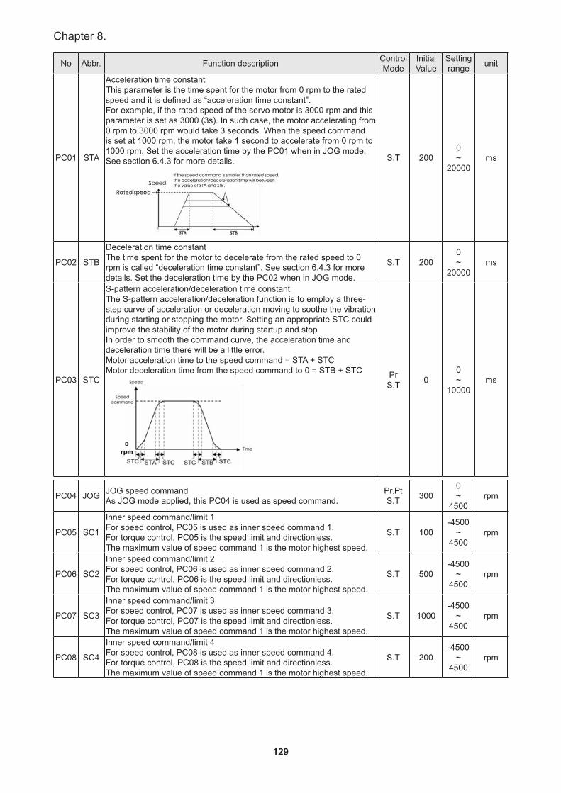
129
Chapter 8.
No Abbr. Function description Control Mode
Initial Value
Setting range unit
PC01 STA
Acceleration time constantThis parameter is the time spent for the motor from 0 rpm to the rated speed and it is defined as “acceleration time constant”.For example, if the rated speed of the servo motor is 3000 rpm and this parameter is set as 3000 (3s). In such case, the motor accelerating from 0 rpm to 3000 rpm would take 3 seconds. When the speed command is set at 1000 rpm, the motor take 1 second to accelerate from 0 rpm to 1000 rpm. Set the acceleration time by the PC01 when in JOG mode.See section 6.4.3 for more details.
S.T 2000~
20000ms
PC02 STB
Deceleration time constantThe time spent for the motor to decelerate from the rated speed to 0 rpm is called “deceleration time constant”. See section 6.4.3 for more details. Set the deceleration time by the PC02 when in JOG mode.
S.T 2000~
20000ms
PC03 STC
S-pattern acceleration/deceleration time constantThe S-pattern acceleration/deceleration function is to employ a three-step curve of acceleration or deceleration moving to soothe the vibration during starting or stopping the motor. Setting an appropriate STC could improve the stability of the motor during startup and stopIn order to smooth the command curve, the acceleration time and deceleration time there will be a little error. Motor acceleration time to the speed command = STA + STC Motor deceleration time from the speed command to 0 = STB + STC Pr
S.T 00~
10000ms
PC04 JOG JOG speed commandAs JOG mode applied, this PC04 is used as speed command.
Pr.PtS.T 300
0~
4500rpm
PC05 SC1
Inner speed command/limit 1For speed control, PC05 is used as inner speed command 1.For torque control, PC05 is the speed limit and directionless. The maximum value of speed command 1 is the motor highest speed.
S.T 100-4500
~4500
rpm
PC06 SC2
Inner speed command/limit 2 For speed control, PC06 is used as inner speed command 2. For torque control, PC06 is the speed limit and directionless. The maximum value of speed command 1 is the motor highest speed.
S.T 500-4500
~4500
rpm
PC07 SC3
Inner speed command/limit 3For speed control, PC07 is used as inner speed command 3.For torque control, PC07 is the speed limit and directionless.The maximum value of speed command 1 is the motor highest speed.
S.T 1000-4500
~4500
rpm
PC08 SC4
Inner speed command/limit 4For speed control, PC08 is used as inner speed command 4.For torque control, PC08 is the speed limit and directionless. The maximum value of speed command 1 is the motor highest speed.
S.T 200-4500
~4500
rpm
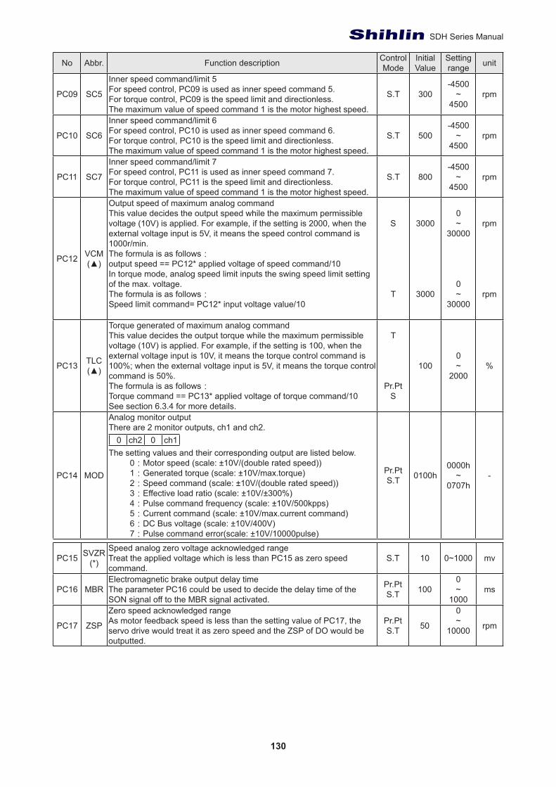
130
SDH Series Manual
No Abbr. Function description Control Mode
Initial Value
Setting range unit
PC09 SC5
Inner speed command/limit 5For speed control, PC09 is used as inner speed command 5.For torque control, PC09 is the speed limit and directionless.The maximum value of speed command 1 is the motor highest speed.
S.T 300-4500
~4500
rpm
PC10 SC6
Inner speed command/limit 6For speed control, PC10 is used as inner speed command 6.For torque control, PC10 is the speed limit and directionless. The maximum value of speed command 1 is the motor highest speed.
S.T 500-4500
~4500
rpm
PC11 SC7
Inner speed command/limit 7For speed control, PC11 is used as inner speed command 7.For torque control, PC11 is the speed limit and directionless.The maximum value of speed command 1 is the motor highest speed.
S.T 800-4500
~4500
rpm
PC12 VCM(▲)
Output speed of maximum analog command This value decides the output speed while the maximum permissible voltage (10V) is applied. For example, if the setting is 2000, when the external voltage input is 5V, it means the speed control command is 1000r/min.The formula is as follows:output speed == PC12* applied voltage of speed command/10 In torque mode, analog speed limit inputs the swing speed limit setting of the max. voltage.The formula is as follows:Speed limit command= PC12* input voltage value/10
S
T
3000
3000
0~
30000
0~
30000
rpm
rpm
PC13 TLC(▲)
Torque generated of maximum analog command This value decides the output torque while the maximum permissible voltage (10V) is applied. For example, if the setting is 100, when the external voltage input is 10V, it means the torque control command is 100%; when the external voltage input is 5V, it means the torque control command is 50%.The formula is as follows:Torque command == PC13* applied voltage of torque command/10 See section 6.3.4 for more details.
T
Pr.PtS
1000~
2000%
PC14 MOD
Analog monitor output There are 2 monitor outputs, ch1 and ch2.
0 ch2 0 ch1The setting values and their corresponding output are listed below.
0:Motor speed (scale: ±10V/(double rated speed))1:Generated torque (scale: ±10V/max.torque)2:Speed command (scale: ±10V/(double rated speed))3:Effective load ratio (scale: ±10V/±300%)4:Pulse command frequency (scale: ±10V/500kpps)5:Current command (scale: ±10V/max.current command)6:DC Bus voltage (scale: ±10V/400V)7:Pulse command error(scale: ±10V/10000pulse)
Pr.PtS.T 0100h
0000h~
0707h-
PC15 SVZR(*)
Speed analog zero voltage acknowledged rangeTreat the applied voltage which is less than PC15 as zero speed command.
S.T 10 0~1000 mv
PC16 MBRElectromagnetic brake output delay timeThe parameter PC16 could be used to decide the delay time of the SON signal off to the MBR signal activated.
Pr.PtS.T 100
0~
1000ms
PC17 ZSP
Zero speed acknowledged rangeAs motor feedback speed is less than the setting value of PC17, the servo drive would treat it as zero speed and the ZSP of DO would be outputted.
Pr.PtS.T 50
0~
10000 rpm
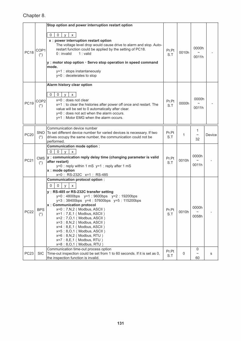
131
Chapter 8.
PC18 COP1(*)
Stop option and power interruption restart option
0 0 y x x:power interruption restart option
The voltage level drop would cause drive to alarm and stop. Auto-restart function could be applied by the setting of PC18. 0 : invalid 1 : valid
y:motor stop option。Servo stop operation in speed command mode.
y=1:stops instantaneouslyy=0:decelerates to stop
Pr.PtS.T 0010h
0000h~
0011h-
PC19 COP2(*)
Alarm history clear option
0 0 y xx=0:does not clear x=1:to clear the histories after power off once and restart. The value will be set to 0 automatically after clear. y=0:does not act when the alarm occurs. y=1:Motor EMG when the alarm occurs.
Pr.PtS.T 0000h
0000h~
0011h-
PC20 SNO(*)
Communication device numberTo set different device number for varied devices is necessary. If two drives occupy the same number, the communication could not be performed.
Pr.PtS.T 1
1~32
Device
PC21 CMS(*)
Communication mode option:0 0 y x
y:communication reply delay time (changing parameter is valid after restart)
y=0:reply within 1 mS y=1:reply after 1 mSx:mode option
x=0: RS-232C x=1: RS-485
Pr.PtS.T 0010h
0000h~
0011h-
PC22 BPS(*)
Communication protocol option:0 0 y x
y:RS-485 or RS-232C transfer settingy=0:4800bps y=1:9600bps y=2:19200bpsy=3:38400bps y=4:57600bps y=5:115200bps
x:Communication protocol x=0:7,N,2(Modbus, ASCII)x=1:7,E,1(Modbus, ASCII)x=2:7,O,1(Modbus, ASCII)x=3:8,N,2(Modbus, ASCII)x=4:8,E,1(Modbus, ASCII)x=5:8,O,1(Modbus, ASCII)x=6:8,N,2(Modbus, RTU)x=7:8,E,1(Modbus, RTU)x=8:8,O,1(Modbus, RTU)
Pr.PtS.T 0010h
0000h~
0058h-
PC23 SICCommunication time-out process optionTime-out inspection could be set from 1 to 60 seconds. If it is set as 0, the inspection function is invalid.
Pr.PtS.T 0
0~60
s
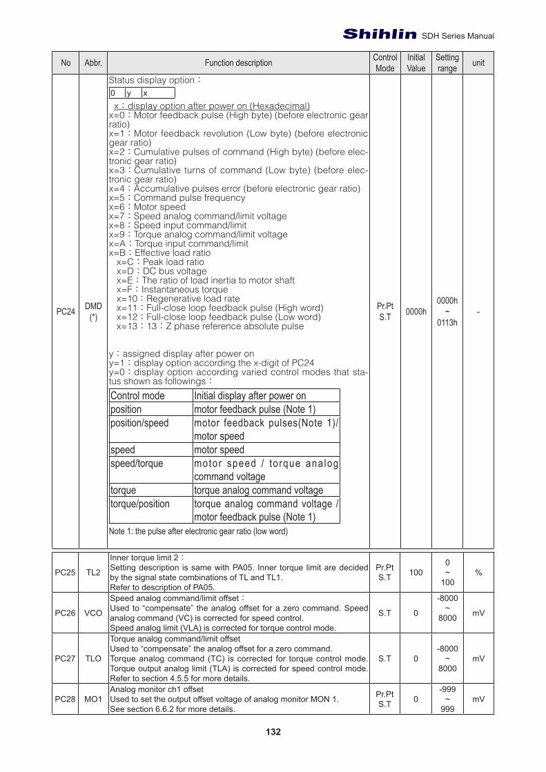
132
SDH Series Manual
No Abbr. Function description Control Mode
Initial Value
Setting range unit
PC24 DMD(*)
Status display option:0 y x x:display option after power on (Hexadecimal)x=0:Motor feedback pulse (High byte) (before electronic gear ratio)x=1:Motor feedback revolution (Low byte) (before electronic gear ratio)x=2:Cumulative pulses of command (High byte) (before elec-tronic gear ratio)x=3:Cumulative turns of command (Low byte) (before elec-tronic gear ratio)x=4:Accumulative pulses error (before electronic gear ratio)x=5:Command pulse frequencyx=6:Motor speedx=7:Speed analog command/limit voltagex=8:Speed input command/limitx=9:Torque analog command/limit voltagex=A:Torque input command/limitx=B:Effective load ratio x=C:Peak load ratio x=D:DC bus voltage x=E:The ratio of load inertia to motor shaft x=F:Instantaneous torque x=10:Regenerative load rate x=11:Full-close loop feedback pulse (High word) x=12:Full-close loop feedback pulse (Low word) x=13:13:Z phase reference absolute pulse
y:assigned display after power on y=1:display option according the x-digit of PC24y=0:display option according varied control modes that sta-tus shown as followings:
Control mode Initial display after power onposition motor feedback pulse (Note 1)position/speed motor feedback pulses(Note 1)/
motor speed speed motor speedspeed/torque motor speed / to rque ana log
command voltagetorque torque analog command voltagetorque/position torque analog command voltage /
motor feedback pulse (Note 1)Note 1: the pulse after electronic gear ratio (low word)
Pr.PtS.T 0000h
0000h~
0113h-
PC25 TL2
Inner torque limit 2:Setting description is same with PA05. Inner torque limit are decided by the signal state combinations of TL and TL1.Refer to description of PA05.
Pr.PtS.T 100
0~
100%
PC26 VCO
Speed analog command/limit offset:Used to “compensate” the analog offset for a zero command. Speed analog command (VC) is corrected for speed control.Speed analog limit (VLA) is corrected for torque control mode.
S.T 0
-8000~
8000 mV
PC27 TLO
Torque analog command/limit offsetUsed to “compensate” the analog offset for a zero command.Torque analog command (TC) is corrected for torque control mode. Torque output analog limit (TLA) is corrected for speed control mode. Refer to section 4.5.5 for more details.
S.T 0-8000
~8000
mV
PC28 MO1Analog monitor ch1 offsetUsed to set the output offset voltage of analog monitor MON 1.See section 6.6.2 for more details.
Pr.PtS.T 0
-999~
999mV
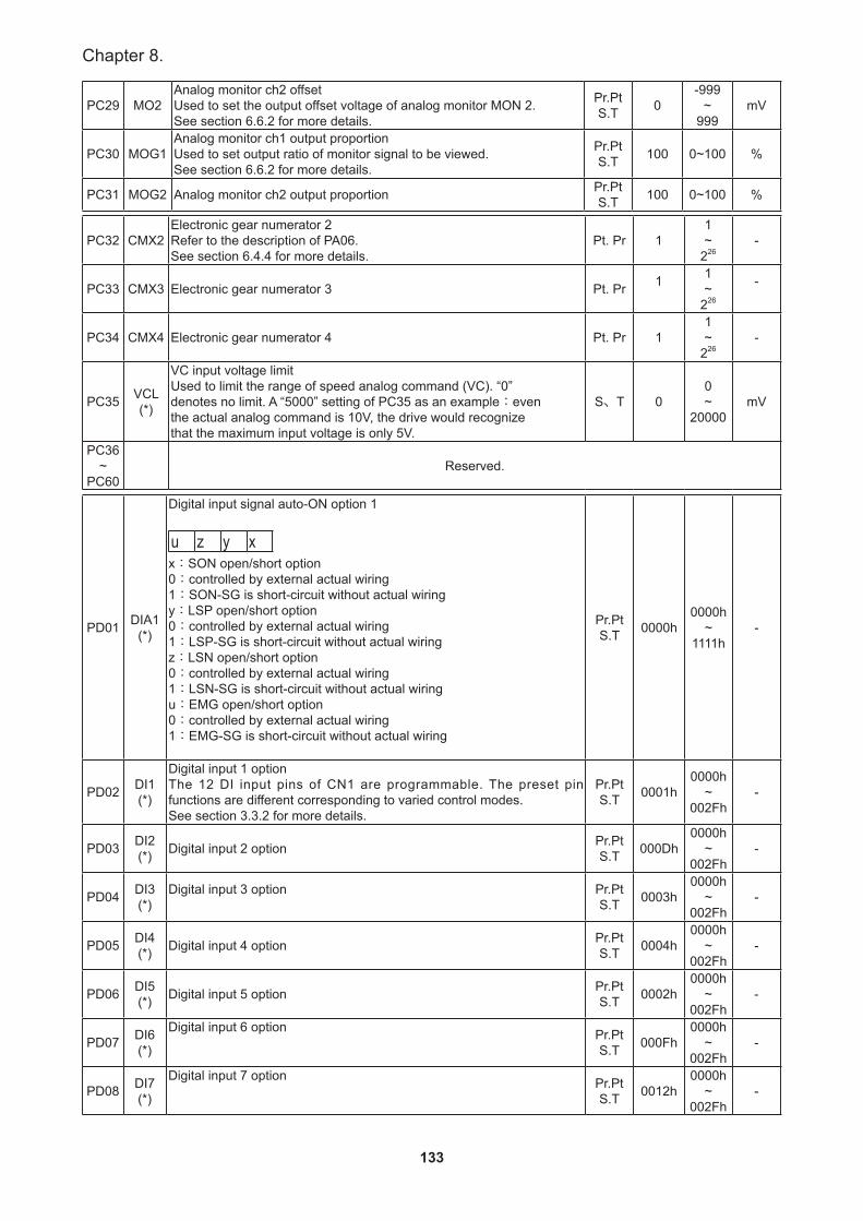
133
Chapter 8.
PC29 MO2Analog monitor ch2 offsetUsed to set the output offset voltage of analog monitor MON 2.See section 6.6.2 for more details.
Pr.PtS.T 0
-999~
999mV
PC30 MOG1Analog monitor ch1 output proportionUsed to set output ratio of monitor signal to be viewed.See section 6.6.2 for more details.
Pr.PtS.T 100 0~100 %
PC31 MOG2 Analog monitor ch2 output proportion Pr.PtS.T 100 0~100 %
PC32 CMX2Electronic gear numerator 2Refer to the description of PA06.See section 6.4.4 for more details.
Pt. Pr 11~
226-
PC33 CMX3 Electronic gear numerator 3 Pt. Pr 1 1~
226
-
PC34 CMX4 Electronic gear numerator 4 Pt. Pr 11~
226-
PC35 VCL(*)
VC input voltage limitUsed to limit the range of speed analog command (VC). “0”denotes no limit. A “5000” setting of PC35 as an example:eventhe actual analog command is 10V, the drive would recognizethat the maximum input voltage is only 5V.
S、T 00~
20000mV
PC36~
PC60Reserved.
PD01 DIA1(*)
Digital input signal auto-ON option 1
u z y xx:SON open/short option0:controlled by external actual wiring1:SON-SG is short-circuit without actual wiringy:LSP open/short option0:controlled by external actual wiring1:LSP-SG is short-circuit without actual wiringz:LSN open/short option0:controlled by external actual wiring1:LSN-SG is short-circuit without actual wiringu:EMG open/short option0:controlled by external actual wiring1:EMG-SG is short-circuit without actual wiring
Pr.PtS.T 0000h
0000h~
1111h-
PD02 DI1(*)
Digital input 1 optionThe 12 DI input pins of CN1 are programmable. The preset pin functions are different corresponding to varied control modes.See section 3.3.2 for more details.
Pr.PtS.T 0001h
0000h~
002Fh-
PD03 DI2(*) Digital input 2 option Pr.Pt
S.T 000Dh0000h
~002Fh
-
PD04 DI3(*)
Digital input 3 option Pr.PtS.T 0003h
0000h~
002Fh-
PD05 DI4(*) Digital input 4 option Pr.Pt
S.T 0004h0000h
~002Fh
-
PD06 DI5(*) Digital input 5 option Pr.Pt
S.T 0002h0000h
~002Fh
-
PD07 DI6(*)
Digital input 6 option Pr.PtS.T 000Fh
0000h~
002Fh-
PD08 DI7(*)
Digital input 7 option Pr.PtS.T 0012h
0000h~
002Fh-
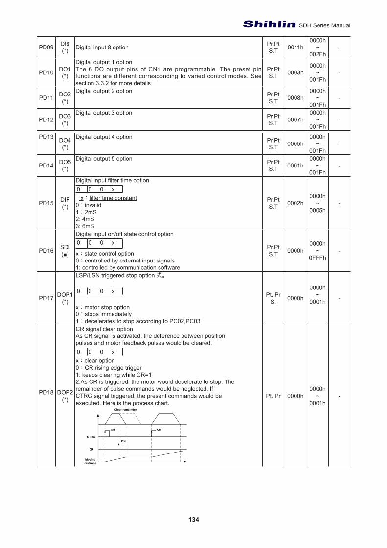
134
SDH Series Manual
PD09 DI8(*) Digital input 8 option Pr.Pt
S.T 0011h0000h
~002Fh
-
PD10 DO1(*)
Digital output 1 optionThe 6 DO output pins of CN1 are programmable. The preset pin functions are different corresponding to varied control modes. See section 3.3.2 for more details
Pr.PtS.T 0003h
0000h~
001Fh-
PD11 DO2(*)
Digital output 2 option Pr.PtS.T 0008h
0000h~
001Fh-
PD12 DO3(*)
Digital output 3 option Pr.PtS.T 0007h
0000h~
001Fh-
PD13 DO4(*)
Digital output 4 option Pr.PtS.T 0005h
0000h~
001Fh-
PD14 DO5(*)
Digital output 5 option Pr.PtS.T 0001h
0000h~
001Fh-
PD15 DIF(*)
Digital input filter time option0 0 0 x x:filter time constant0:invalid1:2mS2: 4mS3: 6mS
Pr.PtS.T 0002h
0000h~
0005h-
PD16 SDI(■)
Digital input on/off state control option0 0 0 x
x:state control option0:controlled by external input signals1: controlled by communication software
Pr.PtS.T 0000h
0000h~
0FFFh-
PD17 DOP1(*)
LSP/LSN triggered stop option 式。
0 0 0 x x:motor stop option0:stops immediately1:decelerates to stop according to PC02,PC03
Pt. PrS. 0000h
0000h~
0001h -
PD18 DOP2(*)
CR signal clear optionAs CR signal is activated, the deference between positionpulses and motor feedback pulses would be cleared.0 0 0 xx:clear option0:CR rising edge trigger1: keeps clearing while CR=12:As CR is triggered, the motor would decelerate to stop. Theremainder of pulse commands would be neglected. IfCTRG signal triggered, the present commands would beexecuted. Here is the process chart.
Pt. Pr 0000h0000h
~0001h
-
Clear remainder
Movingdistance
CTRG
CR
ON ON
ON
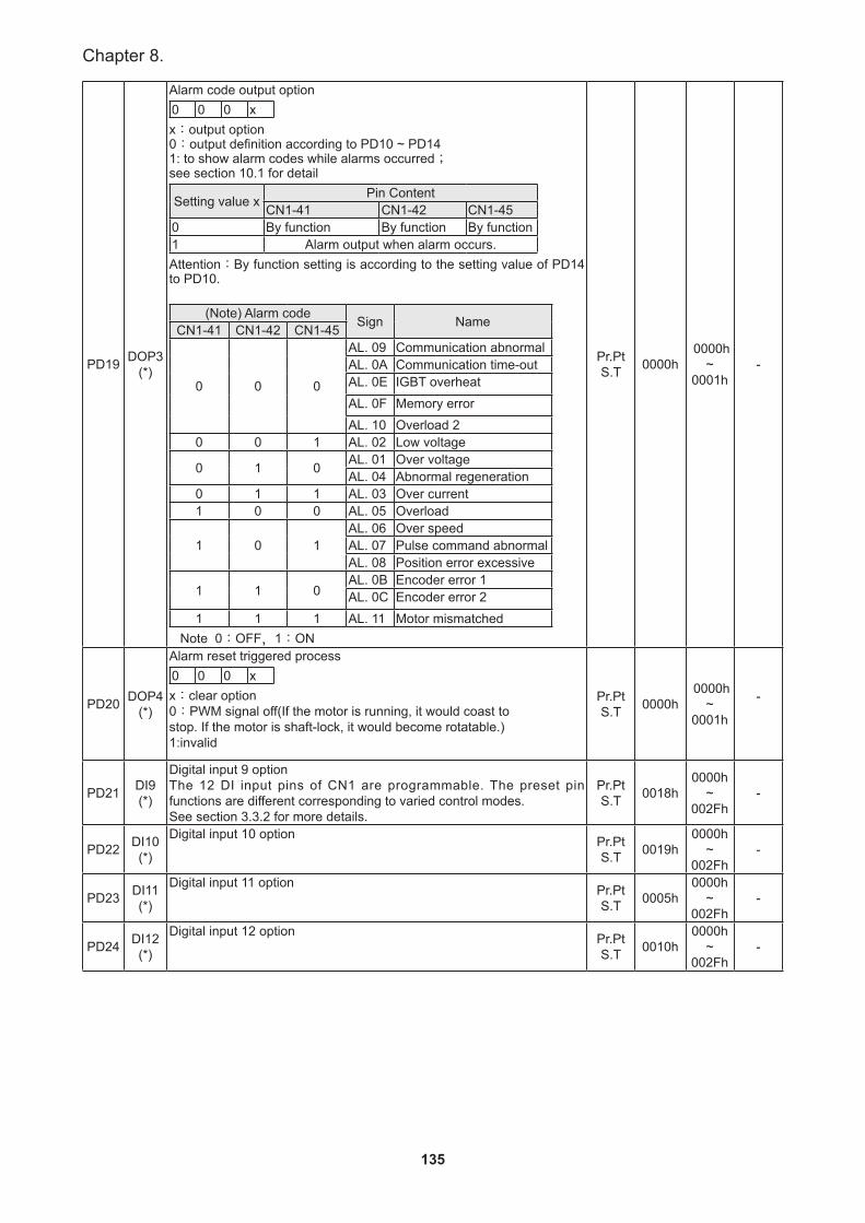
135
Chapter 8.
PD19 DOP3(*)
Alarm code output option0 0 0 xx:output option0:output definition according to PD10 ~ PD141: to show alarm codes while alarms occurred;see section 10.1 for detail
Setting value x Pin ContentCN1-41 CN1-42 CN1-45
0 By function By function By function1 Alarm output when alarm occurs.Attention:By function setting is according to the setting value of PD14 to PD10.
(Note) Alarm code Sign NameCN1-41 CN1-42 CN1-45
0 0 0
AL. 09 Communication abnormalAL. 0A Communication time-outAL. 0E IGBT overheatAL. 0F Memory errorAL. 10 Overload 2
0 0 1 AL. 02 Low voltage
0 1 0 AL. 01 Over voltageAL. 04 Abnormal regeneration
0 1 1 AL. 03 Over current1 0 0 AL. 05 Overload
1 0 1AL. 06 Over speedAL. 07 Pulse command abnormalAL. 08 Position error excessive
1 1 0AL. 0B Encoder error 1AL. 0C Encoder error 2
1 1 1 AL. 11 Motor mismatched Note 0:OFF,1:ON
Pr.PtS.T 0000h
0000h~
0001h-
PD20 DOP4(*)
Alarm reset triggered process0 0 0 xx:clear option0:PWM signal off(If the motor is running, it would coast tostop. If the motor is shaft-lock, it would become rotatable.)1:invalid
Pr.PtS.T 0000h
0000h~
0001h
-
PD21 DI9(*)
Digital input 9 optionThe 12 DI input pins of CN1 are programmable. The preset pin functions are different corresponding to varied control modes.See section 3.3.2 for more details.
Pr.PtS.T 0018h
0000h~
002Fh-
PD22 DI10(*)
Digital input 10 option Pr.PtS.T 0019h
0000h~
002Fh-
PD23 DI11(*)
Digital input 11 option Pr.PtS.T 0005h
0000h~
002Fh-
PD24 DI12(*)
Digital input 12 option Pr.PtS.T 0010h
0000h~
002Fh-
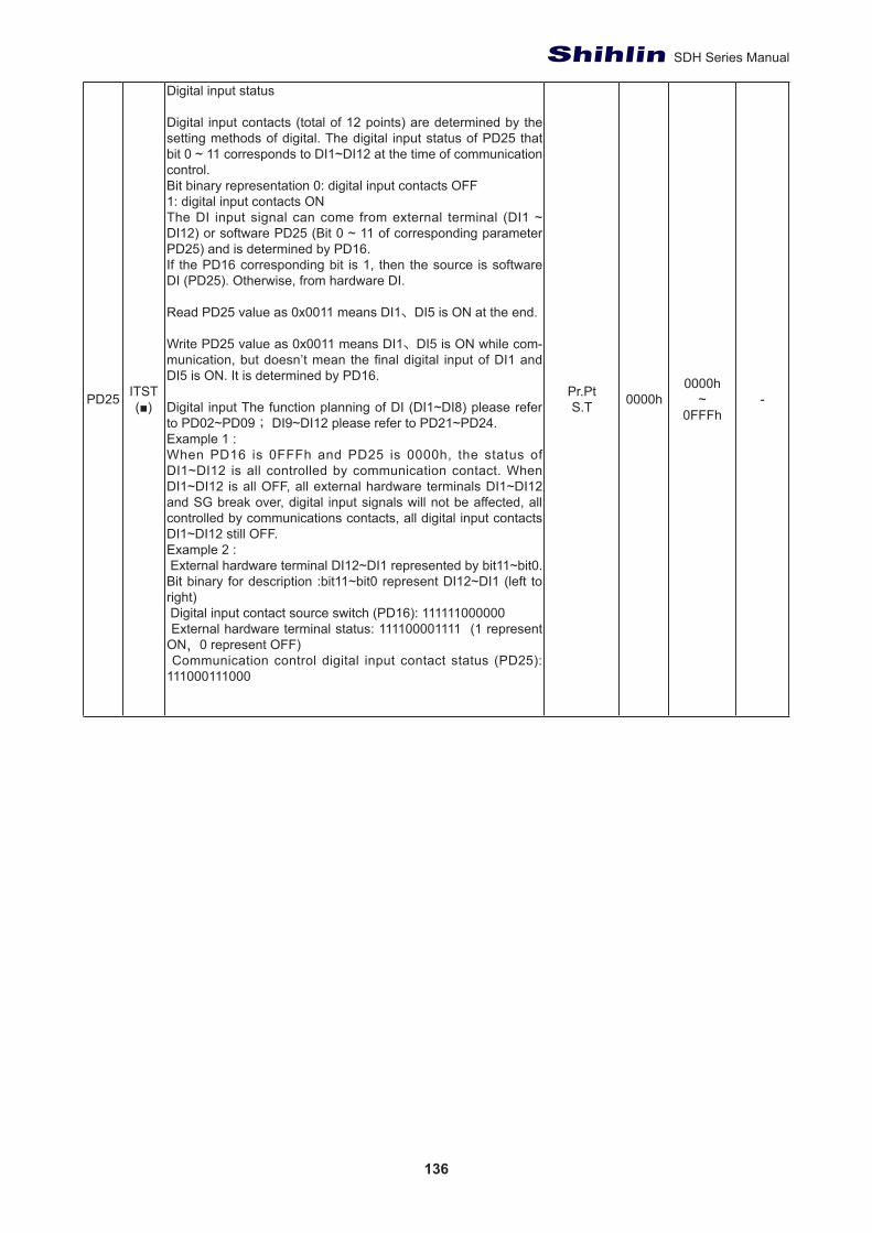
136
SDH Series Manual
PD25 ITST(■)
Digital input status
Digital input contacts (total of 12 points) are determined by the setting methods of digital. The digital input status of PD25 that bit 0 ~ 11 corresponds to DI1~DI12 at the time of communication control. Bit binary representation 0: digital input contacts OFF1: digital input contacts ONThe DI input signal can come from external terminal (DI1 ~ DI12) or software PD25 (Bit 0 ~ 11 of corresponding parameter PD25) and is determined by PD16.If the PD16 corresponding bit is 1, then the source is software DI (PD25). Otherwise, from hardware DI.
Read PD25 value as 0x0011 means DI1、DI5 is ON at the end.
Write PD25 value as 0x0011 means DI1、DI5 is ON while com-munication, but doesn’t mean the final digital input of DI1 and DI5 is ON. It is determined by PD16.
Digital input The function planning of DI (DI1~DI8) please refer to PD02~PD09; DI9~DI12 please refer to PD21~PD24.Example 1 : When PD16 is 0FFFh and PD25 is 0000h, the status of DI1~DI12 is all controlled by communication contact. When DI1~DI12 is all OFF, all external hardware terminals DI1~DI12 and SG break over, digital input signals will not be affected, all controlled by communications contacts, all digital input contacts DI1~DI12 still OFF.Example 2 : External hardware terminal DI12~DI1 represented by bit11~bit0. Bit binary for description :bit11~bit0 represent DI12~DI1 (left to right) Digital input contact source switch (PD16): 111111000000 External hardware terminal status: 111100001111 (1 represent ON,0 represent OFF) Communication control digital input contact status (PD25): 111000111000
Pr.PtS.T 0000h
0000h~
0FFFh-

137
Chapter 8.
No Abbr. Function description Control Mode
Initial Value
Setting range unit
PD26 DO6(*)
Digital output 6 optionThe 6 DO output pins of CN1 are programmable. The preset pin functions are different corresponding to varied control modes.See section 3.3.2 for more details.
Pr.PtS.T 0002h
0000h~
001Fh-
PD27 DOD(*)
Output signal contacts definitionsOutput signal contact of the DO1~DO6 definitionThe parameter value bit0~bit5 representing the DO1~DO6 pin definition defines the output contact for a or b contact 0 : normal open contact A 1 : normal close contact BDigital output logic optionTo defined logic of DO1~ DO6. The bit0~ bit5 corresponds to DI1~ DI6. Contact A or contact B is selectable.0:normal open contact A1:normal close contact B
Pr.PtS.T 0020h
0000h~
003F-
PD28 MCOK
Motion reached(DO:MC_OK)operation options
0 0 y xx=0:Output not remain , x=1:output remain y=0:Position offset warning AL.1B disable y=1:Position offset warning AL.1B enable 1.Command trigger:Pr new command begins valid, command 3 be-gins to output and clear signals of 2, 4, 5, 6. 2.CMD_OK:To check if command 3 finished the output and enable to set delay time DLY。3.Command output: Output position command pattern according to the setting value of acceleration and deceleration speed.4.INP:Check if position error is in the setting range of parameter PA12.5.MC_OK:Indicates that the command output is complete and the servo position is complete too, and signal 2, 4 is AND6.MC_OK(output remain) :Same with 5, but once the output is ON (7) maintained, no matter the signal 4 is OFF。7.Users can only choose one output for signal 5 or signal 6, designated by the parameter PD28.X.8.Position offset:When 7 occurs, if 4(or 5) becomes too OFF means position offset which would trigger AL.1B.The alert can be set from parameter PD28.Y.
Pr 0000h0000h
~0011h
-
PD29~
PD40
Reserved
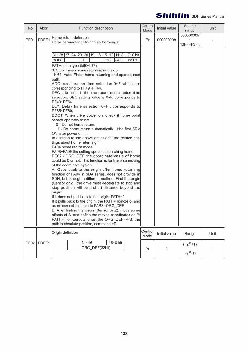
138
SDH Series Manual
No Abbr. Function description Control Mode Initial Value Setting
range unit
PE01 PDEF1 Home return definitionDetail parameter definition as followings: Pr 00000000h
00000000h~
10FFFF3Fh-
31~28 27~24 23~20 19~16 15~12 11~8 7~0 bitBOOT − DLY − DEC1 ACC PATHPATH: path type (bit0~bit7)0: Stop: Finish home returning and stop. 1~63: Auto: Finish home returning and operate next path.ACC: acceleration time selection 0~F which are corresponding to PF49~PF64.DEC1: Section 1 of home return deceleration time selection, DEC setting value is 0~F, corresponds to PF49~PF64. DLY: Delay time selection 0~F , corresponds to PF65~PF80。BOOT: When drive power on, check if home point search operates or not : 0:Do not home return. 1:Do home return automatically.(the first SRV ON after power on)。In addition to the above definitions, the related set-tings about home returning:PA04 home return mode。PA08~PA09 the setting speed of searching home.PE02:ORG_DEF the coordinate value of home could be 0 or not. This function is for traverse moving of the coordinate system.A. Goes back to the origin after home returning function of PA04 in SDA series, does not provide in SDH, but through a different method. Find the origin (Sensor or Z), the drive must decelerate to stop and stop position will be a short distance beyond the origin:If it does not pull back to the origin, PATH=0.If it pulls back to the origin, the PATH= non-zero, and users can set the path to PABS=ORG_DEF.B .After finding the origin (Sensor or Z), move some offsets of S, and define the moved coordinates as P: PATH= non-zero, and set the ORG_DEF=P-S, the path is absolute position, command =P.
PE02 PDEF1
Origin definition
31~16 15~0 bitORG_DEF(32bit)
Control mode Initial value Range Unit
Pr 0(−231+1)
~ (231-1)
-
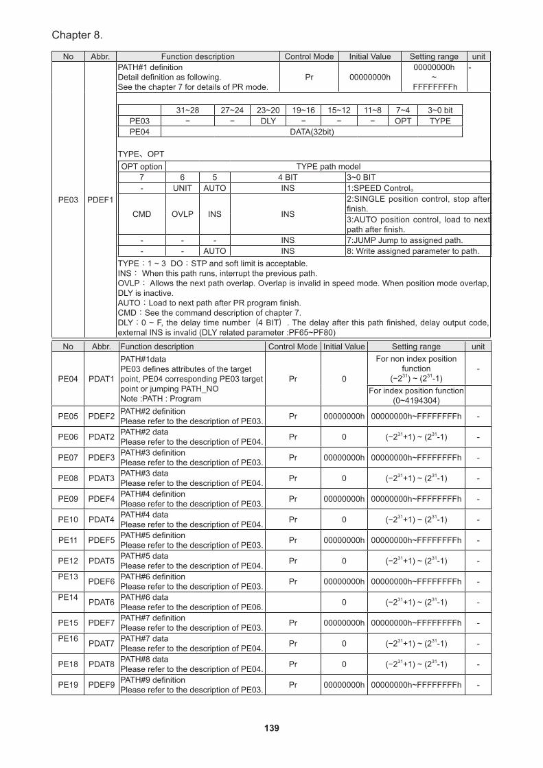
139
Chapter 8.
No Abbr. Function description Control Mode Initial Value Setting range unit
PE03 PDEF1
PATH#1 definitionDetail definition as following. See the chapter 7 for details of PR mode.
Pr 00000000h00000000h
~ FFFFFFFFh
-
31~28 27~24 23~20 19~16 15~12 11~8 7~4 3~0 bit
PE03 − − DLY − − − OPT TYPEPE04 DATA(32bit)
TYPE、OPTOPT option TYPE path model
7 6 5 4 BIT 3~0 BIT- UNIT AUTO INS 1:SPEED Control。
CMD OVLP INS INS
2:SINGLE position control, stop after finish.3:AUTO position control, load to next path after finish.
- - - INS 7:JUMP Jump to assigned path.- - AUTO INS 8: Write assigned parameter to path.
TYPE:1 ~ 3 DO:STP and soft limit is acceptable.INS: When this path runs, interrupt the previous path.OVLP: Allows the next path overlap. Overlap is invalid in speed mode. When position mode overlap, DLY is inactive.AUTO:Load to next path after PR program finish.CMD:See the command description of chapter 7. DLY:0 ~ F, the delay time number(4 BIT). The delay after this path finished, delay output code, external INS is invalid (DLY related parameter :PF65~PF80)
No Abbr. Function description Control Mode Initial Value Setting range unit
PE04 PDAT1
PATH#1dataPE03 defines attributes of the target point, PE04 corresponding PE03 target point or jumping PATH_NONote :PATH : Program
Pr 0
For non index position function
(−231) ~ (231-1)-
For index position function(0~4194304)
PE05 PDEF2 PATH#2 definitionPlease refer to the description of PE03. Pr 00000000h 00000000h~FFFFFFFFh -
PE06 PDAT2 PATH#2 dataPlease refer to the description of PE04. Pr 0 (−231+1) ~ (231-1) -
PE07 PDEF3 PATH#3 definitionPlease refer to the description of PE03. Pr 00000000h 00000000h~FFFFFFFFh -
PE08 PDAT3 PATH#3 dataPlease refer to the description of PE04. Pr 0 (−231+1) ~ (231-1) -
PE09 PDEF4 PATH#4 definitionPlease refer to the description of PE03. Pr 00000000h 00000000h~FFFFFFFFh -
PE10 PDAT4 PATH#4 dataPlease refer to the description of PE04. Pr 0 (−231+1) ~ (231-1) -
PE11 PDEF5 PATH#5 definitionPlease refer to the description of PE03. Pr 00000000h 00000000h~FFFFFFFFh -
PE12 PDAT5 PATH#5 dataPlease refer to the description of PE04. Pr 0 (−231+1) ~ (231-1) -
PE13 PDEF6 PATH#6 definitionPlease refer to the description of PE03. Pr 00000000h 00000000h~FFFFFFFFh -
PE14 PDAT6 PATH#6 dataPlease refer to the description of PE06. 0 (−231+1) ~ (231-1) -
PE15 PDEF7 PATH#7 definitionPlease refer to the description of PE03. Pr 00000000h 00000000h~FFFFFFFFh -
PE16 PDAT7 PATH#7 dataPlease refer to the description of PE04. Pr 0 (−231+1) ~ (231-1) -
PE18 PDAT8 PATH#8 dataPlease refer to the description of PE04. Pr 0 (−231+1) ~ (231-1) -
PE19 PDEF9 PATH#9 definitionPlease refer to the description of PE03. Pr 00000000h 00000000h~FFFFFFFFh -

140
SDH Series Manual
PE20 PDAT9 PATH#9 dataPlease refer to the description of PE04. Pr 0 (−231+1) ~ (231-1) -
PE21 PDEF10 PATH#10 definitionPlease refer to the description of PE03. Pr 00000000h 00000000h~FFFFFFFFh -
PE22 PDAT10 PATH#10 dataPlease refer to the description of PE04. Pr 0 (−231+1) ~ (231-1) -
PE23 PDEF11 PATH#11 definitionPlease refer to the description of PE03. Pr 00000000h 00000000h~FFFFFFFFh -
PE24 PDAT11 PATH#11 dataPlease refer to the description of PE04. Pr 0 (−231+1) ~ (231-1) -
PE25 PDEF12 PATH#12 definitionPlease refer to the description of PE03. Pr 00000000h 00000000h~FFFFFFFFh -
PE18 PDAT8 PATH#8 dataPlease refer to the description of PE04. Pr 0 (−231+1) ~ (231-1) -
PE17 PDEF8 PATH#8 definitionPlease refer to the description of PE03. Pr 00000000h 00000000h~FFFFFFFFh -
PE19 PDEF9 PATH#9 definitionPlease refer to the description of PE03. Pr 00000000h 00000000h~FFFFFFFFh -
PE20 PDAT9 PATH#9 dataPlease refer to the description of PE04. Pr 0 (−231+1) ~ (231-1) -
PE21 PDEF10 PATH#10 definitionPlease refer to the description of PE03. Pr 00000000h 00000000h~FFFFFFFFh -
PE22 PDAT10 PATH#10 dataPlease refer to the description of PE04. Pr 0 (−231+1) ~ (231-1) -
PE23 PDEF11 PATH#11 definitionPlease refer to the description of PE03. Pr 00000000h 00000000h~FFFFFFFFh -
PE24 PDAT11 PATH#11 dataPlease refer to the description of PE04. Pr 0 (−231+1) ~ (231-1) -
PE25 PDEF12 PATH#12 definitionPlease refer to the description of PE03. Pr 00000000h 00000000h~FFFFFFFFh -
PE26 PDAT12 PATH#12 dataPlease refer to the description of PE04. Pr 0 (−231+1) ~ (231-1) -
PE27 PDEF13 PATH#13 definition Please refer to the description of PE03. Pr 00000000h 00000000h~FFFFFFFFh -
PE28 PDAT13 PATH#13 dataPlease refer to the description of PE04. Pr 0 (−231+1) ~ (231-1) -
PE29 PDEF14 PATH#14 definitionPlease refer to the description of PE03. Pr 00000000h 00000000h~FFFFFFFFh -
PE30 PDAT14 PATH#14 dataPlease refer to the description of PE04. Pr 0 (−231+1) ~ (231-1) -
PE31 PDEF15 PATH#15 definitionPlease refer to the description of PE03. Pr 00000000h 00000000h~FFFFFFFFh -
PE32 PDAT15 PATH#15 dataPlease refer to the description of PE04. Pr 0 (−231+1) ~ (231-1) -
PE33 PDEF16 PATH#16 definition Please refer to the description of PE03. Pr 00000000h 00000000h~FFFFFFFFh -
PE34 PDAT16 PATH#16 dataPlease refer to the description of PE04. Pr 0 (−231+1) ~ (231-1) -
PE35 PDEF17 PATH#17 definitionPlease refer to the description of PE03. Pr 00000000h 00000000h~FFFFFFFFh -
PE36 PDAT17 PATH#17 dataPlease refer to the description of PE04. Pr 0 (−231+1) ~ (231-1) -
PE37 PDEF18 PATH#18 definitionPlease refer to the description of PE03. Pr 00000000h 00000000h~FFFFFFFFh -
PE38 PDAT18 PATH#18 dataPlease refer to the description of PE04. Pr 0 (−231+1) ~ (231-1) -
PE39 PDEF19 PATH#19 definitionPlease refer to the description of PE03. Pr 00000000h 00000000h~FFFFFFFFh -
PE40 PDAT19 PATH#19 dataPlease refer to the description of PE04. Pr 0 (−231+1) ~ (231-1) -
PE41 PDEF20 PATH#20 definitionPlease refer to the description of PE03. Pr 00000000h 00000000h~FFFFFFFFh -

141
Chapter 8.
PE42 PDAT20 PATH#20 dataPlease refer to the description of PE04. Pr 0 (−231+1) ~ (231-1) -
PE43 PDEF21 PATH#21 definitionPlease refer to the description of PE03. Pr 00000000h 00000000h~FFFFFFFFh -
PE44 PDAT21 PATH#21 dataPlease refer to the description of PE04. Pr 0 (−231+1) ~ (231-1) -
PE45 PDEF22 PATH#22 definitionPlease refer to the description of PE03. Pr 00000000h 00000000h~FFFFFFFFh -
PE46 PDAT22 PATH#22 dataPlease refer to the description of PE04. Pr 0 (−231+1) ~ (231-1) -
PE47 PDEF23 PATH#23 definitionPlease refer to the description of PE03. Pr 00000000h 00000000h~FFFFFFFFh -
PE48 PDAT23 PATH#23 dataPlease refer to the description of PE04. Pr 0 (−231+1) ~ (231-1) -
PE49 PDEF24 PATH#24 definitionPlease refer to the description of PE03. Pr 00000000h 00000000h~FFFFFFFFh -
PE50 PDAT24 PATH#24 dataPlease refer to the description of PE04. Pr 0 (−231+1) ~ (231-1) -
PE51 PDEF25 PATH#25 definitionPlease refer to the description of PE03. Pr 00000000h 00000000h~FFFFFFFFh -
PE52 PDAT25 PATH#25 dataPlease refer to the description of PE04. Pr 0 (−231+1) ~ (231-1) -
PE53 PDEF26 PATH#26 definitionPlease refer to the description of PE03. Pr 00000000h 00000000h~FFFFFFFFh -
PE54 PDAT26 PATH#26 dataPlease refer to the description of PE04. Pr 0 (−231+1) ~ (231-1) -
PE55 PDEF27 PATH#27 definitionPlease refer to the description of PE03. Pr 00000000h 00000000h~FFFFFFFFh -
PE56 PDAT27 PATH#27 dataPlease refer to the description of PE04. Pr 0 (−231+1) ~ (231-1) -
PE57 PDEF28 PATH#28 definitionPlease refer to the description of PE03. Pr 00000000h 00000000h~FFFFFFFFh -
PE58 PDAT28 PATH#28 dataPlease refer to the description of PE04. Pr 0 (−231+1) ~ (231-1) -
PE59 PDEF29 PATH#29 definitionPlease refer to the description of PE03. Pr 00000000h 00000000h~FFFFFFFFh -
PE60 PDAT29 PATH#29 dataPlease refer to the description of PE04. Pr 0 (−231+1) ~ (231-1) -
PE61 PDEF30 PATH#30 definitionPlease refer to the description of PE03. Pr 00000000h 00000000h~FFFFFFFFh -
PE62 PDAT30 PATH#30 dataPlease refer to the description of PE04. Pr 0 (−231+1) ~ (231-1) -
PE64 PDAT31 PATH#31 dataPlease refer to the description of PE04. Pr 0 (−231+1) ~ (231-1) -
PE65 PDEF32 PATH#32 definitionPlease refer to the description of PE03. Pr 00000000h 00000000h~FFFFFFFFh -
PE66 PDAT32 PATH#32 dataPlease refer to the description of PE04. Pr 0 (−231+1) ~ (231-1) -
PE63 PDEF31 PATH#31 definitionPlease refer to the description of PE03. Pr 00000000h 00000000h~FFFFFFFFh -
PE67 PDEF33 PATH#33 definitionPlease refer to the description of PE03. Pr 00000000h 00000000h~FFFFFFFFh -
PE68 PDAT33 PATH#33 dataPlease refer to the description of PE04. Pr 0 (−231+1) ~ (231-1) -
PE69 PDEF34 PATH#34 definitionPlease refer to the description of PE03. Pr 00000000h 00000000h~FFFFFFFFh -
PE70 PDAT34 PATH#34 dataPlease refer to the description of PE04. Pr 0 (−231+1) ~ (231-1) -
PE71 PDEF35 PATH#35 definitionPlease refer to the description of PE03. Pr 00000000h 00000000h~FFFFFFFFh -
PE72 PDAT35 PATH#35 dataPlease refer to the description of PE04. Pr 0 (−231+1) ~ (231-1) -
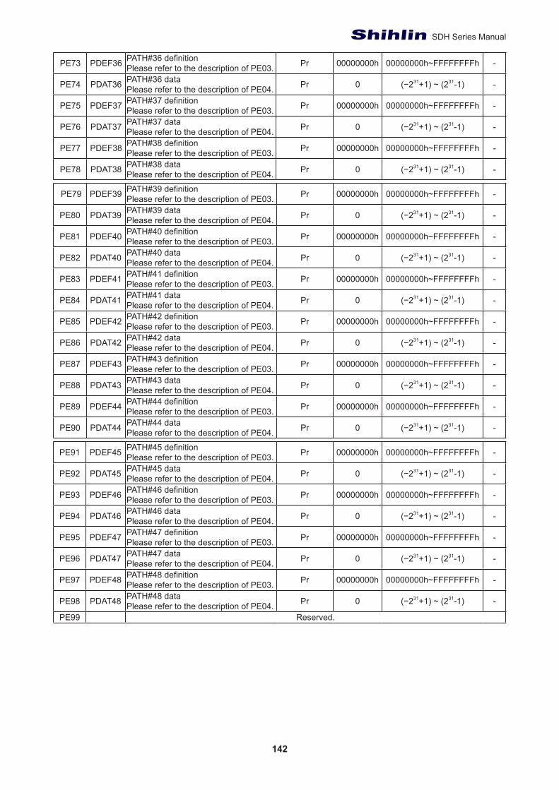
142
SDH Series Manual
PE73 PDEF36 PATH#36 definitionPlease refer to the description of PE03. Pr 00000000h 00000000h~FFFFFFFFh -
PE74 PDAT36 PATH#36 dataPlease refer to the description of PE04. Pr 0 (−231+1) ~ (231-1) -
PE75 PDEF37 PATH#37 definitionPlease refer to the description of PE03. Pr 00000000h 00000000h~FFFFFFFFh -
PE76 PDAT37 PATH#37 dataPlease refer to the description of PE04. Pr 0 (−231+1) ~ (231-1) -
PE77 PDEF38 PATH#38 definitionPlease refer to the description of PE03. Pr 00000000h 00000000h~FFFFFFFFh -
PE78 PDAT38 PATH#38 dataPlease refer to the description of PE04. Pr 0 (−231+1) ~ (231-1) -
PE79 PDEF39 PATH#39 definitionPlease refer to the description of PE03. Pr 00000000h 00000000h~FFFFFFFFh -
PE80 PDAT39 PATH#39 dataPlease refer to the description of PE04. Pr 0 (−231+1) ~ (231-1) -
PE81 PDEF40 PATH#40 definitionPlease refer to the description of PE03. Pr 00000000h 00000000h~FFFFFFFFh -
PE82 PDAT40 PATH#40 dataPlease refer to the description of PE04. Pr 0 (−231+1) ~ (231-1) -
PE83 PDEF41 PATH#41 definitionPlease refer to the description of PE03. Pr 00000000h 00000000h~FFFFFFFFh -
PE84 PDAT41 PATH#41 dataPlease refer to the description of PE04. Pr 0 (−231+1) ~ (231-1) -
PE85 PDEF42 PATH#42 definitionPlease refer to the description of PE03. Pr 00000000h 00000000h~FFFFFFFFh -
PE86 PDAT42 PATH#42 dataPlease refer to the description of PE04. Pr 0 (−231+1) ~ (231-1) -
PE87 PDEF43 PATH#43 definitionPlease refer to the description of PE03. Pr 00000000h 00000000h~FFFFFFFFh -
PE88 PDAT43 PATH#43 dataPlease refer to the description of PE04. Pr 0 (−231+1) ~ (231-1) -
PE89 PDEF44 PATH#44 definitionPlease refer to the description of PE03. Pr 00000000h 00000000h~FFFFFFFFh -
PE90 PDAT44 PATH#44 dataPlease refer to the description of PE04. Pr 0 (−231+1) ~ (231-1) -
PE91 PDEF45 PATH#45 definitionPlease refer to the description of PE03. Pr 00000000h 00000000h~FFFFFFFFh -
PE92 PDAT45 PATH#45 dataPlease refer to the description of PE04. Pr 0 (−231+1) ~ (231-1) -
PE93 PDEF46 PATH#46 definitionPlease refer to the description of PE03. Pr 00000000h 00000000h~FFFFFFFFh -
PE94 PDAT46 PATH#46 dataPlease refer to the description of PE04. Pr 0 (−231+1) ~ (231-1) -
PE95 PDEF47 PATH#47 definitionPlease refer to the description of PE03. Pr 00000000h 00000000h~FFFFFFFFh -
PE96 PDAT47 PATH#47 dataPlease refer to the description of PE04. Pr 0 (−231+1) ~ (231-1) -
PE97 PDEF48 PATH#48 definitionPlease refer to the description of PE03. Pr 00000000h 00000000h~FFFFFFFFh -
PE98 PDAT48 PATH#48 dataPlease refer to the description of PE04. Pr 0 (−231+1) ~ (231-1) -
PE99 Reserved.
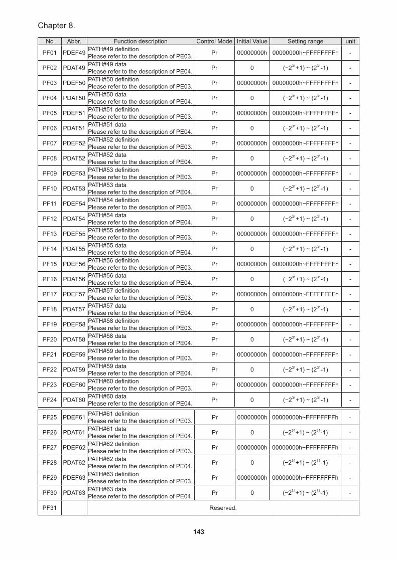
143
Chapter 8.
No Abbr. Function description Control Mode Initial Value Setting range unit
PF01 PDEF49 PATH#49 definitionPlease refer to the description of PE03. Pr 00000000h 00000000h~FFFFFFFFh -
PF02 PDAT49 PATH#49 dataPlease refer to the description of PE04. Pr 0 (−231+1) ~ (231-1) -
PF03 PDEF50 PATH#50 definitionPlease refer to the description of PE03. Pr 00000000h 00000000h~FFFFFFFFh -
PF04 PDAT50 PATH#50 dataPlease refer to the description of PE04. Pr 0 (−231+1) ~ (231-1) -
PF05 PDEF51 PATH#51 definitionPlease refer to the description of PE03. Pr 00000000h 00000000h~FFFFFFFFh -
PF06 PDAT51 PATH#51 dataPlease refer to the description of PE04. Pr 0 (−231+1) ~ (231-1) -
PF07 PDEF52 PATH#52 definitionPlease refer to the description of PE03. Pr 00000000h 00000000h~FFFFFFFFh -
PF08 PDAT52 PATH#52 dataPlease refer to the description of PE04. Pr 0 (−231+1) ~ (231-1) -
PF09 PDEF53 PATH#53 definitionPlease refer to the description of PE03. Pr 00000000h 00000000h~FFFFFFFFh -
PF10 PDAT53 PATH#53 dataPlease refer to the description of PE04. Pr 0 (−231+1) ~ (231-1) -
PF11 PDEF54 PATH#54 definitionPlease refer to the description of PE03. Pr 00000000h 00000000h~FFFFFFFFh -
PF12 PDAT54 PATH#54 dataPlease refer to the description of PE04. Pr 0 (−231+1) ~ (231-1) -
PF13 PDEF55 PATH#55 definitionPlease refer to the description of PE03. Pr 00000000h 00000000h~FFFFFFFFh -
PF14 PDAT55 PATH#55 dataPlease refer to the description of PE04. Pr 0 (−231+1) ~ (231-1) -
PF15 PDEF56 PATH#56 definitionPlease refer to the description of PE03. Pr 00000000h 00000000h~FFFFFFFFh -
PF16 PDAT56 PATH#56 dataPlease refer to the description of PE04. Pr 0 (−231+1) ~ (231-1) -
PF17 PDEF57 PATH#57 definitionPlease refer to the description of PE03. Pr 00000000h 00000000h~FFFFFFFFh -
PF18 PDAT57 PATH#57 dataPlease refer to the description of PE04. Pr 0 (−231+1) ~ (231-1) -
PF19 PDEF58 PATH#58 definitionPlease refer to the description of PE03. Pr 00000000h 00000000h~FFFFFFFFh -
PF20 PDAT58 PATH#58 dataPlease refer to the description of PE04. Pr 0 (−231+1) ~ (231-1) -
PF21 PDEF59 PATH#59 definitionPlease refer to the description of PE03. Pr 00000000h 00000000h~FFFFFFFFh -
PF22 PDAT59 PATH#59 dataPlease refer to the description of PE04. Pr 0 (−231+1) ~ (231-1) -
PF23 PDEF60 PATH#60 definitionPlease refer to the description of PE03. Pr 00000000h 00000000h~FFFFFFFFh -
PF24 PDAT60 PATH#60 dataPlease refer to the description of PE04. Pr 0 (−231+1) ~ (231-1) -
PF25 PDEF61 PATH#61 definitionPlease refer to the description of PE03. Pr 00000000h 00000000h~FFFFFFFFh -
PF26 PDAT61 PATH#61 dataPlease refer to the description of PE04. Pr 0 (−231+1) ~ (231-1) -
PF27 PDEF62 PATH#62 definitionPlease refer to the description of PE03. Pr 00000000h 00000000h~FFFFFFFFh -
PF28 PDAT62 PATH#62 dataPlease refer to the description of PE04. Pr 0 (−231+1) ~ (231-1) -
PF29 PDEF63 PATH#63 definitionPlease refer to the description of PE03. Pr 00000000h 00000000h~FFFFFFFFh -
PF30 PDAT63 PATH#63 dataPlease refer to the description of PE04. Pr 0 (−231+1) ~ (231-1) -
PF31 Reserved.
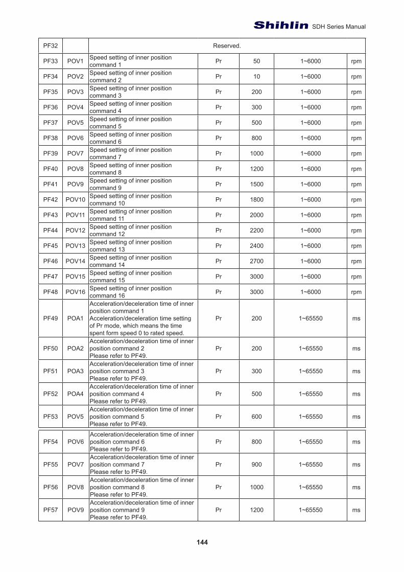
144
SDH Series Manual
PF32 Reserved.
PF33 POV1 Speed setting of inner position command 1 Pr 50 1~6000 rpm
PF34 POV2 Speed setting of inner position command 2 Pr 10 1~6000 rpm
PF35 POV3 Speed setting of inner position command 3 Pr 200 1~6000 rpm
PF36 POV4 Speed setting of inner position command 4 Pr 300 1~6000 rpm
PF37 POV5 Speed setting of inner position command 5 Pr 500 1~6000 rpm
PF38 POV6 Speed setting of inner position command 6 Pr 800 1~6000 rpm
PF39 POV7 Speed setting of inner position command 7 Pr 1000 1~6000 rpm
PF40 POV8 Speed setting of inner position command 8 Pr 1200 1~6000 rpm
PF41 POV9 Speed setting of inner position command 9 Pr 1500 1~6000 rpm
PF42 POV10 Speed setting of inner position command 10 Pr 1800 1~6000 rpm
PF43 POV11 Speed setting of inner position command 11 Pr 2000 1~6000 rpm
PF44 POV12 Speed setting of inner position command 12 Pr 2200 1~6000 rpm
PF45 POV13 Speed setting of inner position command 13 Pr 2400 1~6000 rpm
PF46 POV14 Speed setting of inner position command 14 Pr 2700 1~6000 rpm
PF47 POV15 Speed setting of inner position command 15 Pr 3000 1~6000 rpm
PF48 POV16 Speed setting of inner position command 16 Pr 3000 1~6000 rpm
PF49 POA1
Acceleration/deceleration time of inner position command 1Acceleration/deceleration time setting of Pr mode, which means the time spent form speed 0 to rated speed.
Pr 200 1~65550 ms
PF50 POA2Acceleration/deceleration time of inner position command 2Please refer to PF49.
Pr 200 1~65550 ms
PF51 POA3Acceleration/deceleration time of inner position command 3Please refer to PF49.
Pr 300 1~65550 ms
PF52 POA4Acceleration/deceleration time of inner position command 4Please refer to PF49.
Pr 500 1~65550 ms
PF53 POV5Acceleration/deceleration time of inner position command 5Please refer to PF49.
Pr 600 1~65550 ms
PF54 POV6Acceleration/deceleration time of inner position command 6Please refer to PF49.
Pr 800 1~65550 ms
PF55 POV7Acceleration/deceleration time of inner position command 7Please refer to PF49.
Pr 900 1~65550 ms
PF56 POV8Acceleration/deceleration time of inner position command 8Please refer to PF49.
Pr 1000 1~65550 ms
PF57 POV9Acceleration/deceleration time of inner position command 9Please refer to PF49.
Pr 1200 1~65550 ms
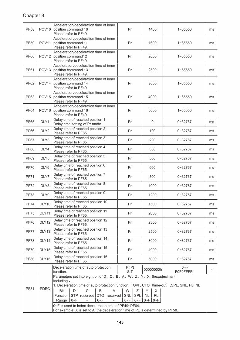
145
Chapter 8.
PF58 POV10Acceleration/deceleration time of inner position command 10Please refer to PF49.
Pr 1400 1~65550 ms
PF59 POV11Acceleration/deceleration time of inner position command 11Please refer to PF49.
Pr 1600 1~65550 ms
PF60 POV12Acceleration/deceleration time of inner position command12Please refer to PF49.
Pr 2000 1~65550 ms
PF61 POV13Acceleration/deceleration time of inner position command 13Please refer to PF49.
Pr 2500 1~65550 ms
PF62 POV14Acceleration/deceleration time of inner position command 14Please refer to PF49.
Pr 3000 1~65550 ms
PF63 POV15Acceleration/deceleration time of inner position command 15Please refer to PF49.
Pr 4000 1~65550 ms
PF64 POV16Acceleration/deceleration time of inner position command 16Please refer to PF49.
Pr 5000 1~65550 ms
PF65 DLY1 Delay time of reached position 1Delay time setting of Pr mode Pr 0 0~32767 ms
PF66 DLY2 Delay time of reached position 2Please refer to PF65. Pr 100 0~32767 ms
PF67 DLY3 Delay time of reached position 3Please refer to PF65. Pr 200 0~32767 ms
PF68 DLY4 Delay time of reached position 4Please refer to PF65. Pr 300 0~32767 ms
PF69 DLY5 Delay time of reached position 5Please refer to PF65. Pr 500 0~32767 ms
PF70 DLY6 Delay time of reached position 6Please refer to PF65. Pr 600 0~32767 ms
PF71 DLY7 Delay time of reached position 7Please refer to PF65. Pr 800 0~32767 ms
PF72 DLY8 Delay time of reached position 8Please refer to PF65. Pr 1000 0~32767 ms
PF73 DLY9 Delay time of reached position 9Please refer to PF65. Pr 1200 0~32767 ms
PF74 DLY10 Delay time of reached position 10Please refer to PF65. Pr 1500 0~32767 ms
PF75 DLY11 Delay time of reached position 11Please refer to PF65. Pr 2000 0~32767 ms
PF76 DLY12 Delay time of reached position 12Please refer to PF65. Pr 2300 0~32767 ms
PF77 DLY13 Delay time of reached position 13Please refer to PF65. Pr 2500 0~32767 ms
PF78 DLY14 Delay time of reached position 14Please refer to PF65. Pr 3000 0~32767 ms
PF79 DLY15 Delay time of reached position 15Please refer to PF65. Pr 4000 0~32767 ms
PF80 DLY16 Delay time of reached position 16Please refer to PF65. Pr 5000 0~32767 ms
PF81 PDEC
Deceleration time of auto protection function.
Pr.PtS.T 00000000h 0~~
F0F0FFFFh -
Parameters set into eight bit of D、C、B、A、W、Z、Y、X(hexadecimal):Including:1. Deceleration time of auto protection function.:OVF, CTO(time-out),SPL, SNL, PL, NL
Bit D C B A W Z Y XFunction STP reserved CTO reserved SNL SPL NL PLRange 0~F − 0~F - 0~F 0~F 0~F 0~F
0~F is used to index deceleration time of PF49~PF64.For example, X is set to A; the deceleration time of PL is determined by PF58.
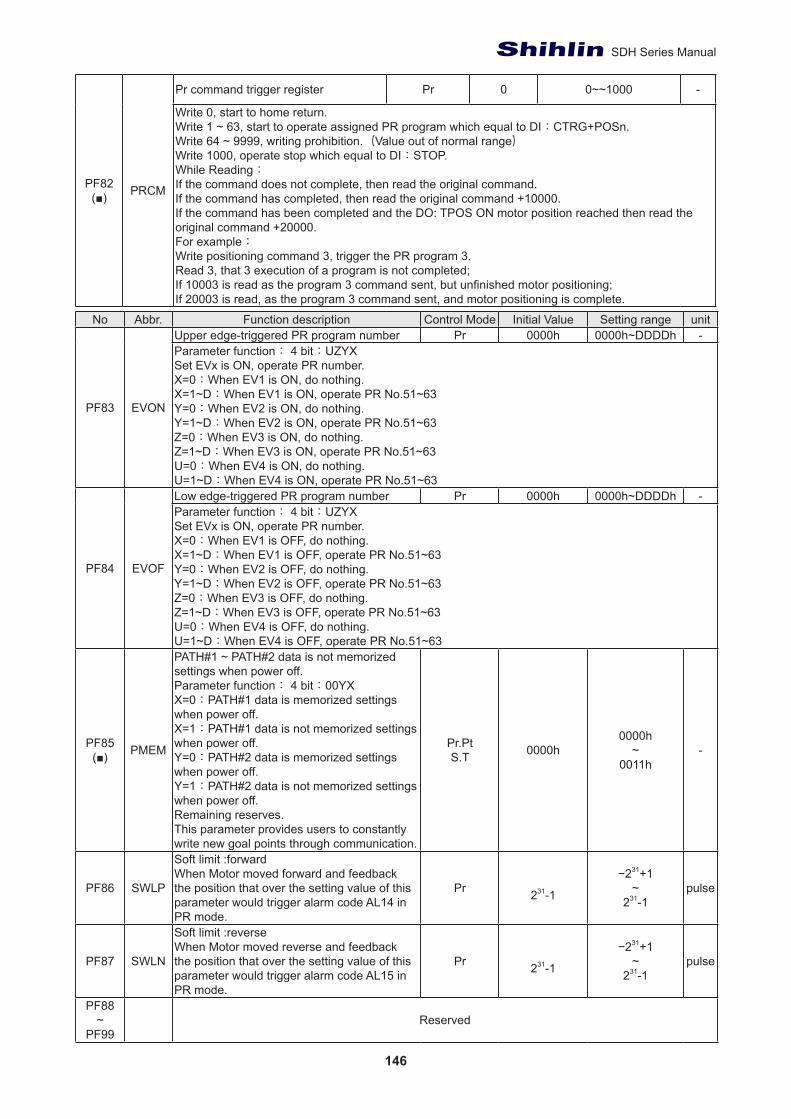
146
SDH Series Manual
PF82(■) PRCM
Pr command trigger register Pr 0 0~~1000 -
Write 0, start to home return.Write 1 ~ 63, start to operate assigned PR program which equal to DI:CTRG+POSn.Write 64 ~ 9999, writing prohibition.(Value out of normal range)Write 1000, operate stop which equal to DI:STOP.While Reading:If the command does not complete, then read the original command.If the command has completed, then read the original command +10000.If the command has been completed and the DO: TPOS ON motor position reached then read the original command +20000.For example:Write positioning command 3, trigger the PR program 3.Read 3, that 3 execution of a program is not completed;If 10003 is read as the program 3 command sent, but unfinished motor positioning;If 20003 is read, as the program 3 command sent, and motor positioning is complete.
No Abbr. Function description Control Mode Initial Value Setting range unit
PF83 EVON
Upper edge-triggered PR program number Pr 0000h 0000h~DDDDh -Parameter function: 4 bit:UZYXSet EVx is ON, operate PR number.X=0:When EV1 is ON, do nothing.X=1~D:When EV1 is ON, operate PR No.51~63Y=0:When EV2 is ON, do nothing.Y=1~D:When EV2 is ON, operate PR No.51~63Z=0:When EV3 is ON, do nothing.Z=1~D:When EV3 is ON, operate PR No.51~63U=0:When EV4 is ON, do nothing.U=1~D:When EV4 is ON, operate PR No.51~63
PF84 EVOF
Low edge-triggered PR program number Pr 0000h 0000h~DDDDh -Parameter function: 4 bit:UZYXSet EVx is ON, operate PR number.X=0:When EV1 is OFF, do nothing.X=1~D:When EV1 is OFF, operate PR No.51~63Y=0:When EV2 is OFF, do nothing.Y=1~D:When EV2 is OFF, operate PR No.51~63Z=0:When EV3 is OFF, do nothing.Z=1~D:When EV3 is OFF, operate PR No.51~63U=0:When EV4 is OFF, do nothing.U=1~D:When EV4 is OFF, operate PR No.51~63
PF85(■) PMEM
PATH#1 ~ PATH#2 data is not memorized settings when power off.Parameter function: 4 bit:00YXX=0:PATH#1 data is memorized settings when power off.X=1:PATH#1 data is not memorized settings when power off.Y=0:PATH#2 data is memorized settings when power off.Y=1:PATH#2 data is not memorized settings when power off.Remaining reserves.This parameter provides users to constantly write new goal points through communication.
Pr.PtS.T 0000h
0000h~
0011h-
PF86 SWLP
Soft limit :forwardWhen Motor moved forward and feedback the position that over the setting value of this parameter would trigger alarm code AL14 in PR mode.
Pr 231-1
−231+1~
231-1pulse
PF87 SWLN
Soft limit :reverseWhen Motor moved reverse and feedback the position that over the setting value of this parameter would trigger alarm code AL15 in PR mode.
Pr 231-1
−231+1~
231-1pulse
PF88~
PF99Reserved
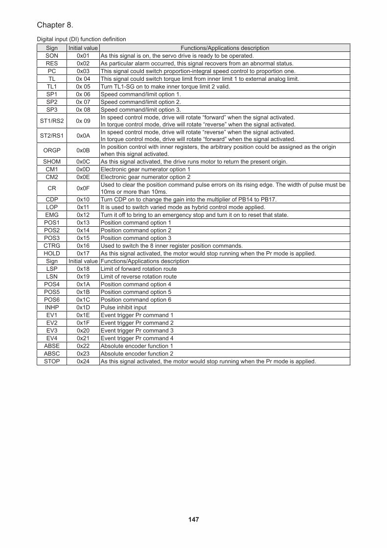
147
Chapter 8.
Digital input (DI) function definitionSign Initial value Functions/Applications descriptionSON 0x01 As this signal is on, the servo drive is ready to be operated.RES 0x02 As particular alarm occurred, this signal recovers from an abnormal status.PC 0x03 This signal could switch proportion-integral speed control to proportion one.TL 0x 04 This signal could switch torque limit from inner limit 1 to external analog limit.
TL1 0x 05 Turn TL1-SG on to make inner torque limit 2 valid.SP1 0x 06 Speed command/limit option 1.SP2 0x 07 Speed command/limit option 2.SP3 0x 08 Speed command/limit option 3.
ST1/RS2 0x 09 In speed control mode, drive will rotate “forward” when the signal activated.In torque control mode, drive will rotate “reverse” when the signal activated.
ST2/RS1 0x0A In speed control mode, drive will rotate “reverse” when the signal activated.In torque control mode, drive will rotate “forward” when the signal activated.
ORGP 0x0B In position control with inner registers, the arbitrary position could be assigned as the origin when this signal activated.
SHOM 0x0C As this signal activated, the drive runs motor to return the present origin.CM1 0x0D Electronic gear numerator option 1CM2 0x0E Electronic gear numerator option 2
CR 0x0F Used to clear the position command pulse errors on its rising edge. The width of pulse must be 10ms or more than 10ms.
CDP 0x10 Turn CDP on to change the gain into the multiplier of PB14 to PB17.LOP 0x11 It is used to switch varied mode as hybrid control mode applied.EMG 0x12 Turn it off to bring to an emergency stop and turn it on to reset that state.POS1 0x13 Position command option 1POS2 0x14 Position command option 2POS3 0x15 Position command option 3CTRG 0x16 Used to switch the 8 inner register position commands.HOLD 0x17 As this signal activated, the motor would stop running when the Pr mode is applied.Sign Initial value Functions/Applications descriptionLSP 0x18 Limit of forward rotation routeLSN 0x19 Limit of reverse rotation route
POS4 0x1A Position command option 4POS5 0x1B Position command option 5POS6 0x1C Position command option 6INHP 0x1D Pulse inhibit inputEV1 0x1E Event trigger Pr command 1EV2 0x1F Event trigger Pr command 2EV3 0x20 Event trigger Pr command 3EV4 0x21 Event trigger Pr command 4
ABSE 0x22 Absolute encoder function 1ABSC 0x23 Absolute encoder function 2STOP 0x24 As this signal activated, the motor would stop running when the Pr mode is applied.
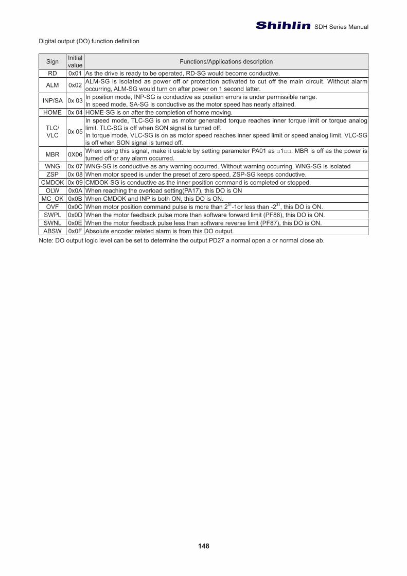
148
SDH Series Manual
Digital output (DO) function definition
Sign Initial value Functions/Applications description
RD 0x01 As the drive is ready to be operated, RD-SG would become conductive.
ALM 0x02 ALM-SG is isolated as power off or protection activated to cut off the main circuit. Without alarm occurring, ALM-SG would turn on after power on 1 second latter.
INP/SA 0x 03 In position mode, INP-SG is conductive as position errors is under permissible range.In speed mode, SA-SG is conductive as the motor speed has nearly attained.
HOME 0x 04 HOME-SG is on after the completion of home moving.
TLC/VLC 0x 05
In speed mode, TLC-SG is on as motor generated torque reaches inner torque limit or torque analog limit. TLC-SG is off when SON signal is turned off.In torque mode, VLC-SG is on as motor speed reaches inner speed limit or speed analog limit. VLC-SG is off when SON signal is turned off.
MBR 0X06 When using this signal, make it usable by setting parameter PA01 as □1□□. MBR is off as the power is turned off or any alarm occurred.
WNG 0x 07 WNG-SG is conductive as any warning occurred. Without warning occurring, WNG-SG is isolatedZSP 0x 08 When motor speed is under the preset of zero speed, ZSP-SG keeps conductive.
CMDOK 0x 09 CMDOK-SG is conductive as the inner position command is completed or stopped.OLW 0x0A When reaching the overload setting(PA17), this DO is ON
MC_OK 0x0B When CMDOK and INP is both ON, this DO is ON.OVF 0x0C When motor position command pulse is more than 231-1or less than -231, this DO is ON.
SWPL 0x0D When the motor feedback pulse more than software forward limit (PF86), this DO is ON.SWNL 0x0E When the motor feedback pulse less than software reverse limit (PF87), this DO is ON.ABSW 0x0F Absolute encoder related alarm is from this DO output.
Note: DO output logic level can be set to determine the output PD27 a normal open a or normal close ab.
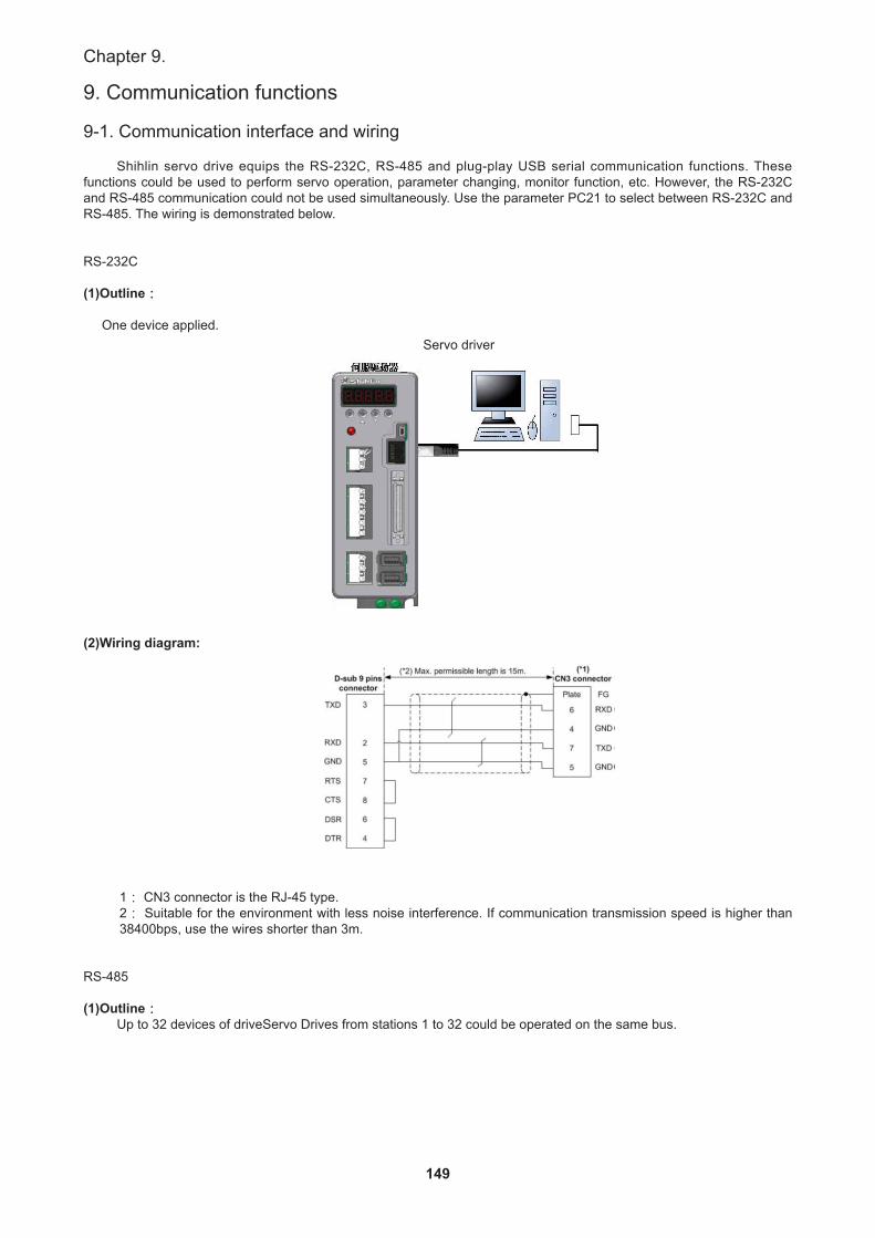
149
Chapter 9.
9. Communication functions
9-1. Communication interface and wiring
Shihlin servo drive equips the RS-232C, RS-485 and plug-play USB serial communication functions. These functions could be used to perform servo operation, parameter changing, monitor function, etc. However, the RS-232C and RS-485 communication could not be used simultaneously. Use the parameter PC21 to select between RS-232C and RS-485. The wiring is demonstrated below.
RS-232C
(1)Outline:
One device applied.
(2)Wiring diagram:
1: CN3 connector is the RJ-45 type.2: Suitable for the environment with less noise interference. If communication transmission speed is higher than 38400bps, use the wires shorter than 3m.
RS-485
(1)Outline:Up to 32 devices of driveServo Drives from stations 1 to 32 could be operated on the same bus.
Servo driver
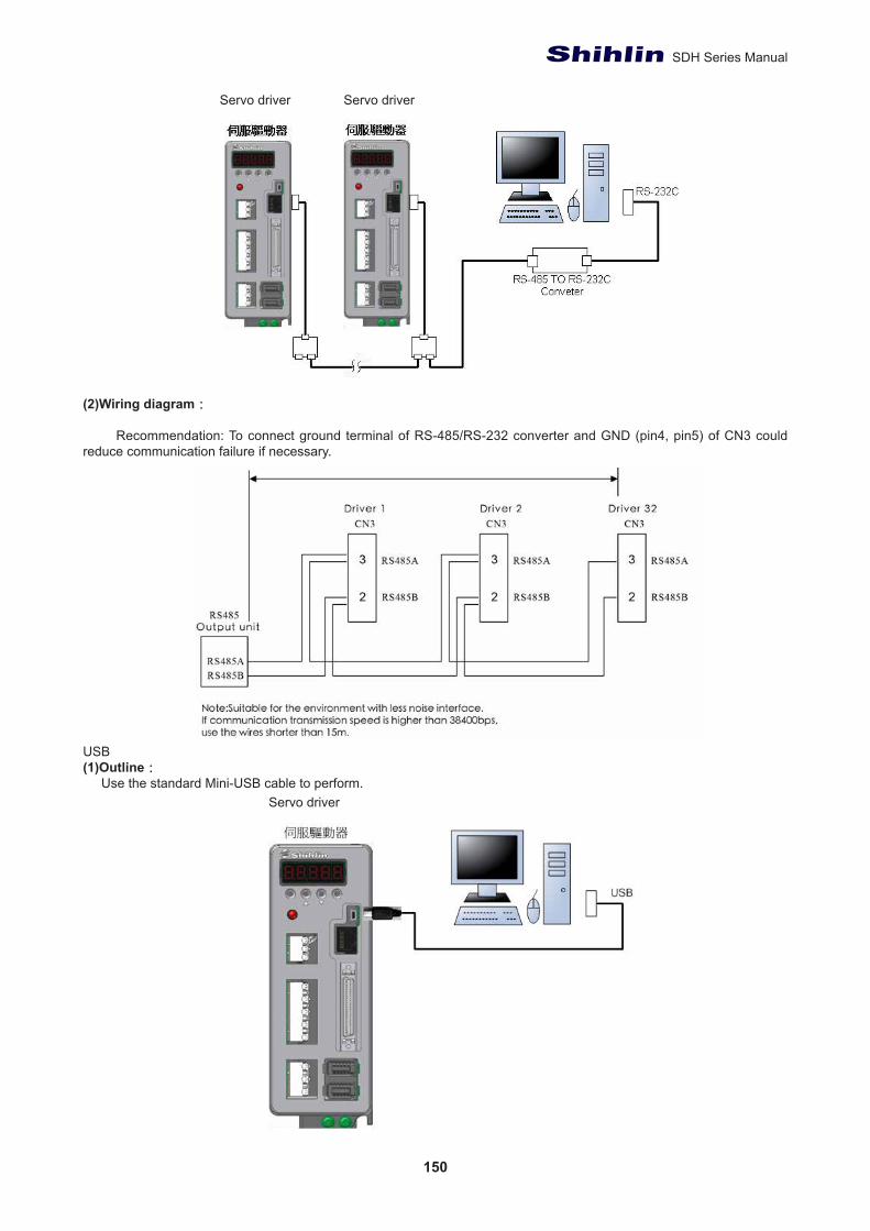
150
SDH Series Manual
(2)Wiring diagram:
Recommendation: To connect ground terminal of RS-485/RS-232 converter and GND (pin4, pin5) of CN3 could reduce communication failure if necessary.
USB(1)Outline: Use the standard Mini-USB cable to perform.
Servo driver Servo driver
Servo driver
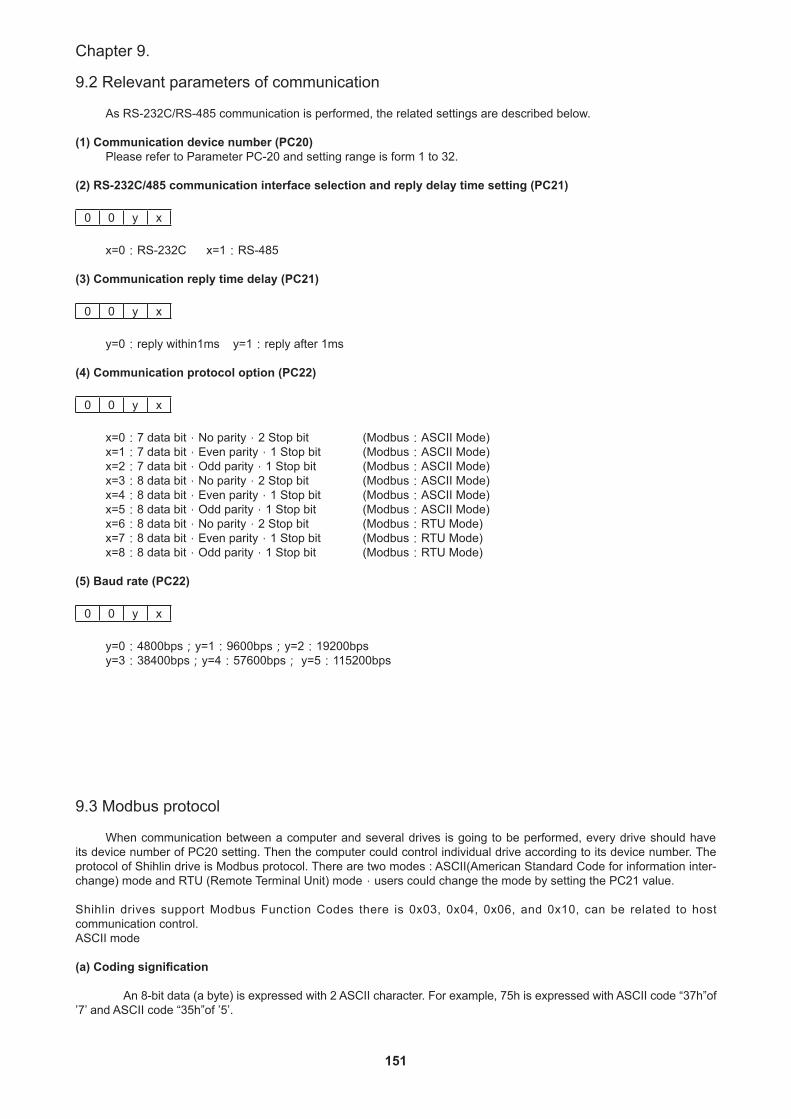
151
Chapter 9.
9.2 Relevant parameters of communication
As RS-232C/RS-485 communication is performed, the related settings are described below.
(1) Communication device number (PC20)Please refer to Parameter PC-20 and setting range is form 1 to 32.
(2) RS-232C/485 communication interface selection and reply delay time setting (PC21)
0 0 y x
x=0:RS-232C x=1:RS-485
(3) Communication reply time delay (PC21)
0 0 y x
y=0:reply within1ms y=1:reply after 1ms (4) Communication protocol option (PC22)
0 0 y x
x=0:7 data bit,No parity,2 Stop bit (Modbus:ASCII Mode)x=1:7 data bit,Even parity,1 Stop bit (Modbus:ASCII Mode)x=2:7 data bit,Odd parity,1 Stop bit (Modbus:ASCII Mode)x=3:8 data bit,No parity,2 Stop bit (Modbus:ASCII Mode)x=4:8 data bit,Even parity,1 Stop bit (Modbus:ASCII Mode)x=5:8 data bit,Odd parity,1 Stop bit (Modbus:ASCII Mode)x=6:8 data bit,No parity,2 Stop bit (Modbus:RTU Mode)x=7:8 data bit,Even parity,1 Stop bit (Modbus:RTU Mode)x=8:8 data bit,Odd parity,1 Stop bit (Modbus:RTU Mode)
(5) Baud rate (PC22)
0 0 y x
y=0:4800bps;y=1:9600bps;y=2:19200bpsy=3:38400bps;y=4:57600bps; y=5:115200bps
9.3 Modbus protocol
When communication between a computer and several drives is going to be performed, every drive should have its device number of PC20 setting. Then the computer could control individual drive according to its device number. The protocol of Shihlin drive is Modbus protocol. There are two modes : ASCII(American Standard Code for information inter-change) mode and RTU (Remote Terminal Unit) mode,users could change the mode by setting the PC21 value.
Shihlin drives support Modbus Function Codes there is 0x03, 0x04, 0x06, and 0x10, can be related to host communication control.ASCII mode
(a) Coding signification
An 8-bit data (a byte) is expressed with 2 ASCII character. For example, 75h is expressed with ASCII code “37h”of ’7’ and ASCII code “35h”of ’5’.

152
SDH Series Manual
(b) frame signification
11 bit frame (suitable for 8-bit data length)
10-bit frame (suitable for 7-bit data length)
(3) Data packet structure
Bit Sign Name DescriptionSTX Start code “:”(3AH of ASCII)ADR Device number 1 byte is composed of 2 ASCII code bytes.CMD Command code 1 byte is composed of 2 ASCII code bytes.
DATA(n-1) Data code The length of n words is equal to the one of 2n bytes.(n<=29)So, there are 4n ASCII code bytes.
………DATA(0)
LRC LRC check value 1 byte is composed of 2 ASCII code bytes.End1 End code 1 0DH of ASCII (CR)End0 End code 0 0AH of ASCII (LF)
Communication data formats are described below.
STX (Start code)’:’ character
ADR (Device number)
The address code is from 1 to 32. For example, communicate with device number 18(hexadecimal 12h) ADR=’1’,’2’ = > ’1’=31H,’2’=32H
CMD and DATA
The DATA are varied according to different Command codes. Command codes for common use are described below.
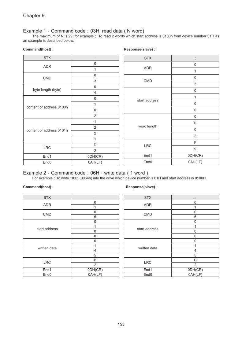
153
Chapter 9.
Example 1,Command code:03H, read data ( N word)The maximum of N is 29; for example: To read 2 words which start address is 0100h from device number 01H as
an example is described below.
Command(host): Response(slave):
Example 2,Command code:06H,write data(1 word)For example:To write “100” (0064h) into the drive which device number is 01H and start address is 0100H.
Command(host): Response(slave):
STX :
ADR01
CMD03
byte length (byte)04
content of address 0100h
0102
content of address 0101h
1221
LRCD2
End1 0DH(CR)End0 0AH(LF)
STX :
ADR0
1
CMD0
3
start address
0
1
0
0
word length
0
0
0
2
LRCF
9
End1 0DH(CR)
End0 0AH(LF)
STX :
ADR 01
CMD 06
start address
0100
written data
0145
LRC B2
End1 0DH(CR)End0 0AH(LF)
STX :
ADR 01
CMD 06
start address
0100
written data
0145
LRC B2
End1 0DH(CR)End0 0AH(LF)
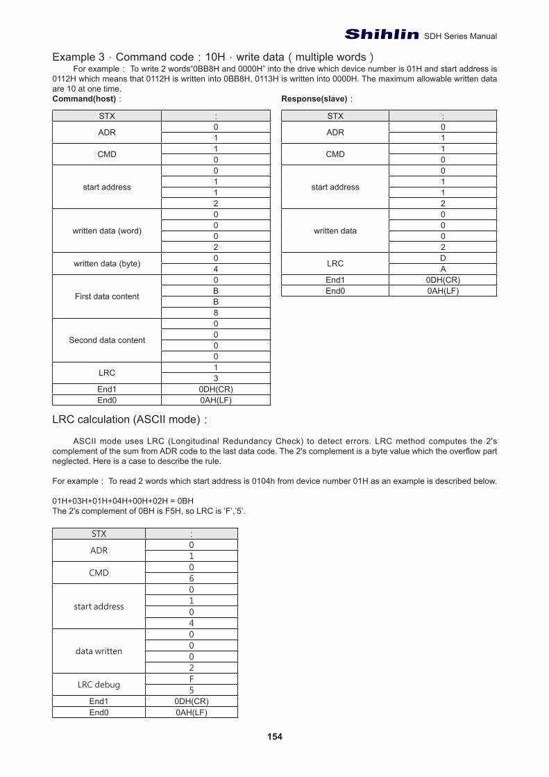
154
SDH Series Manual
Example 3,Command code:10H,write data(multiple words)For example: To write 2 words“0BB8H and 0000H” into the drive which device number is 01H and start address is
0112H which means that 0112H is written into 0BB8H, 0113H is written into 0000H. The maximum allowable written data are 10 at one time.Command(host): Response(slave):
LRC calculation (ASCII mode):
ASCII mode uses LRC (Longitudinal Redundancy Check) to detect errors. LRC method computes the 2's complement of the sum from ADR code to the last data code. The 2's complement is a byte value which the overflow part neglected. Here is a case to describe the rule.
For example: To read 2 words which start address is 0104h from device number 01H as an example is described below.
01H+03H+01H+04H+00H+02H = 0BHThe 2's complement of 0BH is F5H, so LRC is ’F’,’5’.
STX :
ADR01
CMD06
start address
0104
data written
0002
LRC debugF5
End1 0DH(CR)End0 0AH(LF)
STX :
ADR 01
CMD 10
start address
0112
written data
0002
LRC DA
End1 0DH(CR)End0 0AH(LF)
STX :
ADR 01
CMD 10
start address
0112
written data (word)
0002
written data (byte) 04
First data content
0BB8
Second data content
0000
LRC 13
End1 0DH(CR)End0 0AH(LF)
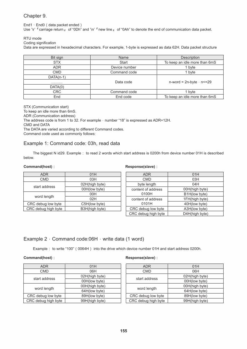
155
Chapter 9.
End1、End0(data packet ended)Use ’\r’『carriage return』 of “0Dh” and ’\n’『new line』 of “0Ah” to denote the end of communication data packet.
RTU modeCoding significationData are expressed in hexadecimal characters. For example, 1-byte is expressed as data 62H. Data packet structure
Bit sign Name DescriptionSTX Start To keep an idle more than 6mSADR Device number 1 byteCMD Command code 1 byte
DATA(n-1)Data code n-word = 2n-byte,n<=29………
DATA(0)CRC Command code 1 byte End End code To keep an idle more than 6mS
STX (Communication start)To keep an idle more than 6mS.ADR (Communication address)The address code is from 1 to 32. For example,number “18” is expressed as ADR=12H.CMD and DATAThe DATA are varied according to different Command codes. Command code used as commonly follows:
Example 1: Command code: 03h, read data
The biggest N id29. Example: to read 2 words which start address is 0200h from device number 01H is described below.
Command(host): Response(slave):
Example 2,Command code:06H,write data (1 word)
Example: to write “100”(0064H) into the drive which device number 01H and start address 0200h.
Command(host): Response(slave):
ADR 01HCMD 03H
start address 02H(high byte)00H(low byte)
word length 00H02H
CRC debug low byte C5H(low byte)CRC debug high byte B3H(high byte)
ADR 01HCMD 03H
byte length 04Hcontent of address
0100H00H(high byte)B1H(low byte)
content of address0101H
1FH(high byte)40H(low byte)
CRC debug low byte A3H(low byte)CRC debug high byte D4H(high byte)
ADR 01HCMD 06H
start address 02H(high byte)00H(low byte)
word length 00H(high byte)64H(low byte)
CRC debug low byte 89H(low byte)CRC debug high byte 99H(high byte)
ADR 01HCMD 06H
start address 02H(high byte)00H(low byte)
word length 00H(high byte)64H(low byte)
CRC debug low byte 89H(low byte)CRC debug high byte 99H(high byte)
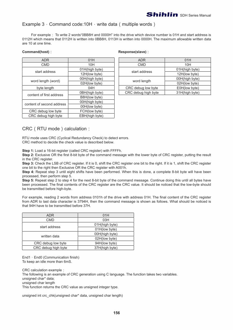
156
SDH Series Manual
Example 3,Command code:10H,write data(multiple words)
For example: To write 2 words“0BB8H and 0000H” into the drive which device number is 01H and start address is 0112H which means that 0112H is written into 0BB8H, 0113H is written into 0000H. The maximum allowable written data are 10 at one time.
Command(host): Response(slave):
CRC(RTU mode)calculation:
RTU mode uses CRC (Cyclical Redundancy Check) to detect errors.CRC method to decide the check value is described below.
Step 1: Load a 16-bit register (called CRC register) with FFFFh.Step 2: Exclusive OR the first 8-bit byte of the command message with the lower byte of CRC register, putting the result in the CRC register.Step 3: Check the LSB of CRC register. If it is 0, shift the CRC register one bit to the right. If it is 1, shift the CRC register one bit to the right then Exclusive OR the CRC register with A001h.Step 4: Repeat step 3 until eight shifts have been performed. When this is done, a complete 8-bit byte will have been processed, then perform step 5.Step 5: Repeat step 2 to step 4 for the next 8-bit byte of the command message. Continue doing this until all bytes have been processed. The final contents of the CRC register are the CRC value. It should be noticed that the low-byte should be transmitted before high-byte.
For example, reading 2 words from address 0101h of the drive with address 01H. The final content of the CRC register from ADR to last data character is 3794H, then the command message is shown as follows. What should be noticed is that 94H have to be transmitted before 37H.
ADR 01HCMD 03H
start address 01H(high byte)01H(low byte)
written data 00H(high byte)02H(low byte)
CRC debug low byte 94H(low byte)CRC debug high byte 37H(high byte)
End1、End0 (Communication finish)To keep an idle more than 6mS.
CRC calculation example:The following is an example of CRC generation using C language. The function takes two variables. unsigned char* data; unsigned char length This function returns the CRC value as unsigned integer type.
unsigned int crc_chk(unsigned char* data, unsigned char length)
ADR 01HCMD 10H
start address 01H(high byte)12H(low byte)
word length (word) 00H(high byte)02H(low byte)
byte length 04H
content of first address 0BH(high byte)B8H(low byte)
content of second address 00H(high byte)00H(low byte)
CRC debug low byte FCH(low byte)CRC debug high byte EBH(high byte)
ADR 01HCMD 10H
start address 01H(high byte)12H(low byte)
word length 00H(high byte)02H(low byte)
CRC debug low byte E0H(low byte)CRC debug high byte 31H(high byte)
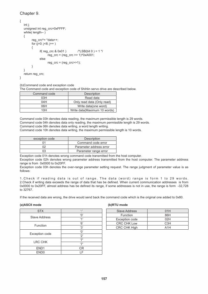
157
Chapter 9.
{int j;unsigned int reg_crc=0xFFFF;while( length-- ) {
reg_crc^= *data++;for (j=0; j<8; j++ ){
if( reg_crc & 0x01 ) /*LSB(bit 0 ) = 1 */reg_crc = (reg_crc >> 1)^0xA001;
else reg_crc = (reg_crc>>1);
}}return reg_crc;
}
(b)Command code and exception codeThe Command code and exception code of Shihlin servo drive are described below.
Command code Description03H Read data04H Only read data (Only read)06H Write data(one word)10H Write data(Maximum 10 words)
Command code 03h denotes data reading, the maximum permissible length is 29 words.Command code 04h denotes data only reading, the maximum permissible length is 29 words.Command code 06h denotes data writing, a word length writing.Command code 10h denotes data writing, the maximum permissible length is 10 words.
exception code Description01 Command code error 02 Parameter address error03 Parameter range error
Exception code 01h denotes wrong command code transmitted from the host computer. Exception code 02h denotes wrong parameter address transmitted from the host computer. The parameter address range is from 0x0000 to 0x20FF.Exception code 03h denotes the over-range parameter setting request. The range judgment of parameter value is as follows:
1 . C h e c k i f r e a d i n g d a t a i s o u t o f r a n g e . T h e d a t a ( w o r d ) r a n g e i s f o r m 1 t o 2 9 w o r d s . 2.Check if writing data exceeds the range of data that has be defined. When current communication addresses is from 0x0000 to 0x20FF, almost address has be defined its range, if some addresses is not in use, the range is form -32,728 to 32767.
If the received data are wrong, the drive would send back the command code which is the original one added to 0x80.
(a)ASCII mode (b)RTU mode
STX ‘:’
Slave Address ‘0’‘1’
Function ‘6’‘3’
Exception code ‘0’‘2’
LRC CHK ‘7’‘7’
END1 CREND0 LF
Slave Address 01HFunction 86H
Exception code 02HCRC CHK Low C3HCRC CHK High A1H
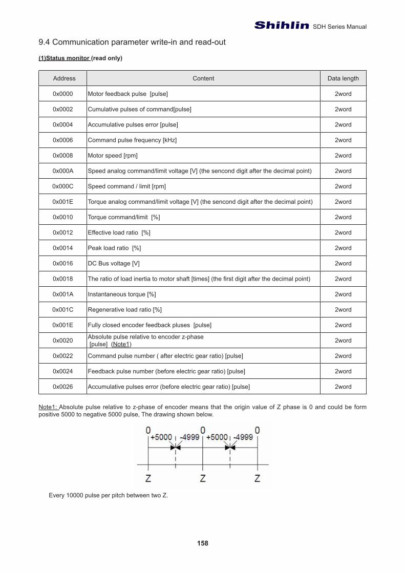
158
SDH Series Manual
9.4 Communication parameter write-in and read-out
(1)Status monitor (read only)
Address Content Data length
0x0000 Motor feedback pulse [pulse] 2word
0x0002 Cumulative pulses of command[pulse] 2word
0x0004 Accumulative pulses error [pulse] 2word
0x0006 Command pulse frequency [kHz] 2word
0x0008 Motor speed [rpm] 2word
0x000A Speed analog command/limit voltage [V] (the sencond digit after the decimal point) 2word
0x000C Speed command / limit [rpm] 2word
0x001E Torque analog command/limit voltage [V] (the sencond digit after the decimal point) 2word
0x0010 Torque command/limit [%] 2word
0x0012 Effective load ratio [%] 2word
0x0014 Peak load ratio [%] 2word
0x0016 DC Bus voltage [V] 2word
0x0018 The ratio of load inertia to motor shaft [times] (the first digit after the decimal point) 2word
0x001A Instantaneous torque [%] 2word
0x001C Regenerative load ratio [%] 2word
0x001E Fully closed encoder feedback pluses [pulse] 2word
0x0020 Absolute pulse relative to encoder z-phase [pulse] (Note1) 2word
0x0022 Command pulse number ( after electric gear ratio) [pulse] 2word
0x0024 Feedback pulse number (before electric gear ratio) [pulse] 2word
0x0026 Accumulative pulses error (before electric gear ratio) [pulse] 2word
Note1: Absolute pulse relative to z-phase of encoder means that the origin value of Z phase is 0 and could be form positive 5000 to negative 5000 pulse, The drawing shown below.
Every 10000 pulse per pitch between two Z.
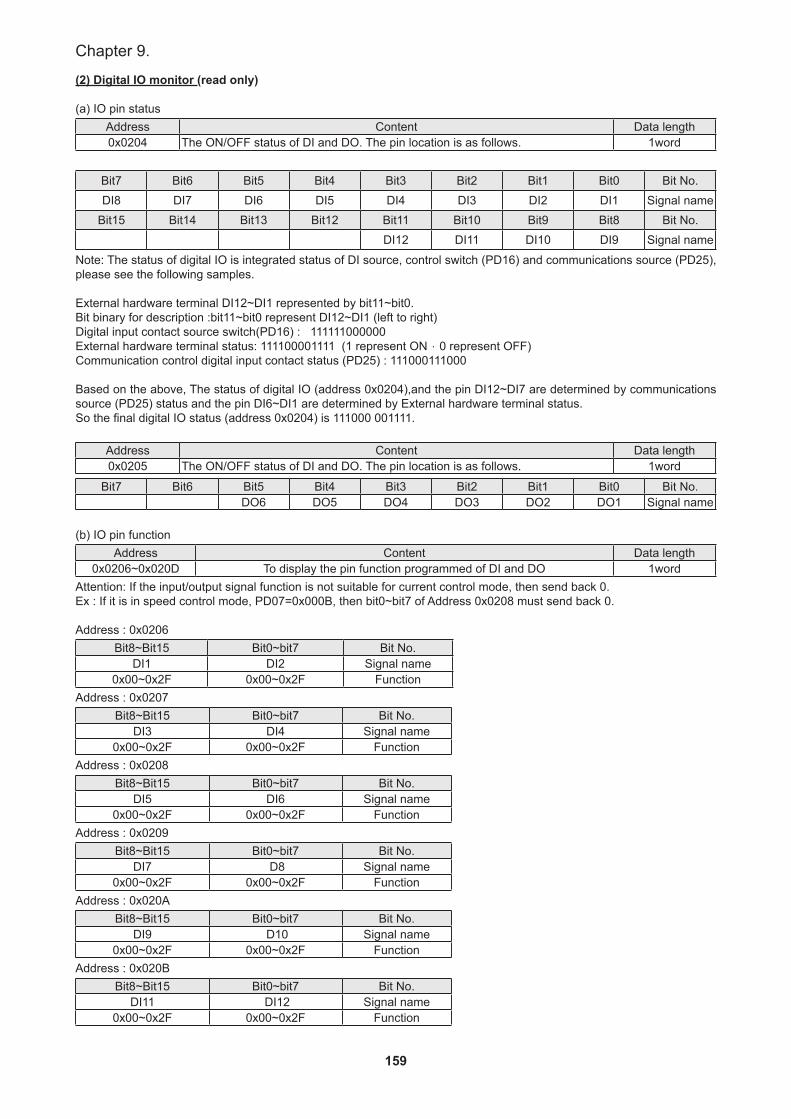
159
Chapter 9.
(2) Digital IO monitor (read only)
(a) IO pin statusAddress Content Data length0x0204 The ON/OFF status of DI and DO. The pin location is as follows. 1word
Bit7 Bit6 Bit5 Bit4 Bit3 Bit2 Bit1 Bit0 Bit No.DI8 DI7 DI6 DI5 DI4 DI3 DI2 DI1 Signal name
Bit15 Bit14 Bit13 Bit12 Bit11 Bit10 Bit9 Bit8 Bit No.DI12 DI11 DI10 DI9 Signal name
Note: The status of digital IO is integrated status of DI source, control switch (PD16) and communications source (PD25), please see the following samples.
External hardware terminal DI12~DI1 represented by bit11~bit0. Bit binary for description :bit11~bit0 represent DI12~DI1 (left to right)Digital input contact source switch(PD16) : 111111000000 External hardware terminal status: 111100001111 (1 represent ON,0 represent OFF)Communication control digital input contact status (PD25) : 111000111000
Based on the above, The status of digital IO (address 0x0204),and the pin DI12~DI7 are determined by communications source (PD25) status and the pin DI6~DI1 are determined by External hardware terminal status.So the final digital IO status (address 0x0204) is 111000 001111.
Address Content Data length0x0205 The ON/OFF status of DI and DO. The pin location is as follows. 1word
Bit7 Bit6 Bit5 Bit4 Bit3 Bit2 Bit1 Bit0 Bit No.DO6 DO5 DO4 DO3 DO2 DO1 Signal name
(b) IO pin functionAddress Content Data length
0x0206~0x020D To display the pin function programmed of DI and DO 1wordAttention: If the input/output signal function is not suitable for current control mode, then send back 0.Ex : If it is in speed control mode, PD07=0x000B, then bit0~bit7 of Address 0x0208 must send back 0.
Address : 0x0206Bit8~Bit15 Bit0~bit7 Bit No.
DI1 DI2 Signal name0x00~0x2F 0x00~0x2F Function
Address : 0x0207Bit8~Bit15 Bit0~bit7 Bit No.
DI3 DI4 Signal name0x00~0x2F 0x00~0x2F Function
Address : 0x0208Bit8~Bit15 Bit0~bit7 Bit No.
DI5 DI6 Signal name0x00~0x2F 0x00~0x2F Function
Address : 0x0209Bit8~Bit15 Bit0~bit7 Bit No.
DI7 D8 Signal name0x00~0x2F 0x00~0x2F Function
Address : 0x020ABit8~Bit15 Bit0~bit7 Bit No.
DI9 D10 Signal name0x00~0x2F 0x00~0x2F Function
Address : 0x020BBit8~Bit15 Bit0~bit7 Bit No.
DI11 DI12 Signal name0x00~0x2F 0x00~0x2F Function
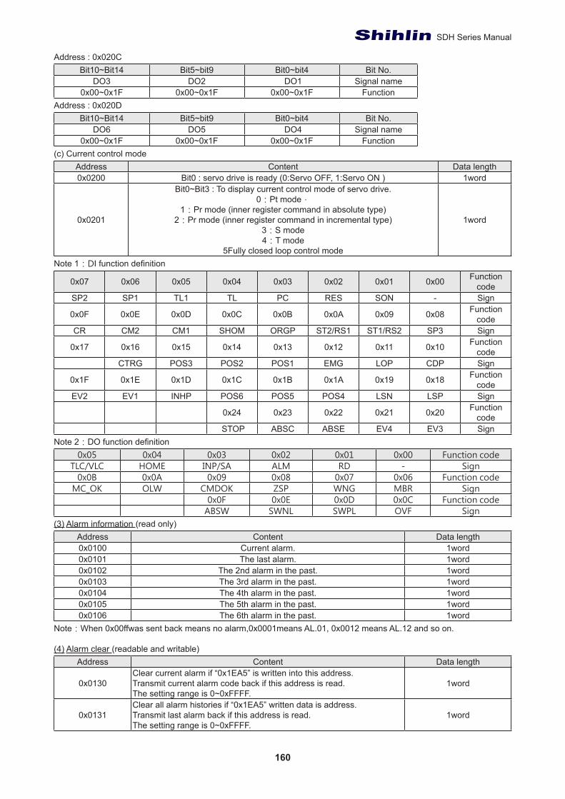
160
SDH Series Manual
Address : 0x020CBit10~Bit14 Bit5~bit9 Bit0~bit4 Bit No.
DO3 DO2 DO1 Signal name0x00~0x1F 0x00~0x1F 0x00~0x1F Function
Address : 0x020DBit10~Bit14 Bit5~bit9 Bit0~bit4 Bit No.
DO6 DO5 DO4 Signal name0x00~0x1F 0x00~0x1F 0x00~0x1F Function
(c) Current control modeAddress Content Data length0x0200 Bit0 : servo drive is ready (0:Servo OFF, 1:Servo ON ) 1word
0x0201
Bit0~Bit3 : To display current control mode of servo drive.0:Pt mode,
1:Pr mode (inner register command in absolute type)2:Pr mode (inner register command in incremental type)
3:S mode4:T mode
5Fully closed loop control mode
1word
Note 1:DI function definition
0x07 0x06 0x05 0x04 0x03 0x02 0x01 0x00 Function code
SP2 SP1 TL1 TL PC RES SON - Sign
0x0F 0x0E 0x0D 0x0C 0x0B 0x0A 0x09 0x08 Function code
CR CM2 CM1 SHOM ORGP ST2/RS1 ST1/RS2 SP3 Sign
0x17 0x16 0x15 0x14 0x13 0x12 0x11 0x10 Function code
CTRG POS3 POS2 POS1 EMG LOP CDP Sign
0x1F 0x1E 0x1D 0x1C 0x1B 0x1A 0x19 0x18 Function code
EV2 EV1 INHP POS6 POS5 POS4 LSN LSP Sign
0x24 0x23 0x22 0x21 0x20 Function code
STOP ABSC ABSE EV4 EV3 SignNote 2:DO function definition
0x05 0x04 0x03 0x02 0x01 0x00 Function codeTLC/VLC HOME INP/SA ALM RD - Sign
0x0B 0x0A 0x09 0x08 0x07 0x06 Function codeMC_OK OLW CMDOK ZSP WNG MBR Sign
0x0F 0x0E 0x0D 0x0C Function codeABSW SWNL SWPL OVF Sign
(3) Alarm information (read only)Address Content Data length0x0100 Current alarm. 1word0x0101 The last alarm. 1word0x0102 The 2nd alarm in the past. 1word0x0103 The 3rd alarm in the past. 1word0x0104 The 4th alarm in the past. 1word0x0105 The 5th alarm in the past. 1word0x0106 The 6th alarm in the past. 1word
Note:When 0x00ffwas sent back means no alarm,0x0001means AL.01, 0x0012 means AL.12 and so on.
(4) Alarm clear (readable and writable)Address Content Data length
0x0130Clear current alarm if “0x1EA5” is written into this address.Transmit current alarm code back if this address is read.The setting range is 0~0xFFFF.
1word
0x0131Clear all alarm histories if “0x1EA5” written data is address.Transmit last alarm back if this address is read. The setting range is 0~0xFFFF.
1word
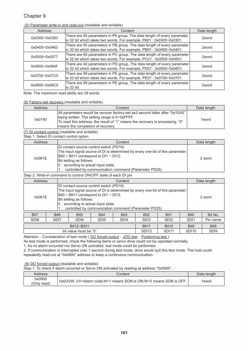
161
Chapter 9.
(5) Parameter write-in and read-out (readable and writable)Address Content Data length
0x0300~0x0363 There are 50 parameters in PA group. The data length of every parameter is 32 bit which takes two words. For example, PA01 : 0x0300~0x0301. 2word
0x0400~0x0463 There are 50 parameters in PB group. The data length of every parameter is 32 bit which takes two words. For example, PB01 : 0x0400~0x0401. 2word
0x0500~0x0577 There are 60 parameters in PC group. The data length of every parameter is 32 bit which takes two words. For example, PC01 : 0x0500~0x0501. 2word
0x0600~0x064F There are 40 parameters in PD group. The data length of every parameter is 32 bit which takes two words. For example, PD01 : 0x0600~0x0601. 2word
0x0700~0x07C5 There are 99 parameters in PE group. The data length of every parameter is 32 bit which takes two words. For example, PE01 : 0x0700~0x0701. 2word
0x0800~0x08C5 There are 99 parameters in PE group. The data length of every parameter is 32 bit. 2word
Note: The maximum read ability are 29 words.
(6) Factory-set recovery (readable and writable)Address Content Data length
0x0140
All parameters would be recover factory-set as3 second latter after “0x1EA5” being written. The setting range is 0~0xFFFF.To read this address, the result of “1” means the recovery is processing. “0” means the completion of recovery.
1word
(7) DI contact control (readable and writable)Step 1: Select DI contact control option
Address Content Data length
0x061E
DI contact source control switch (PD16)The input signal source of DI is determined by every one bit of this parameter:Bit0 ~ Bit11 correspond to DI1 ~ DI12.Bit setting as follows:0:according to actual input state.1: controlled by communication command (Parameter PD25)
2 word
Step 2: Write-in command to control ON/OFF state of each DI pinAddress Content Data length
0x061E
DI contact source control switch (PD16)The input signal source of DI is determined by every one bit of this parameter:Bit0 ~ Bit11 correspond to DI1 ~ DI12.Bit setting as follows:0:according to actual input state.1: controlled by communication command (Parameter PD25)
2 word
Bit7 Bit6 Bit5 Bit4 Bit3 Bit2 Bit1 Bit0 Bit No.SDI8 SDI7 SDI6 SDI5 SDI4 SDI3 SDI2 SDI1 Pin name
Bit12~Bit31 Bit11 Bit10 Bit9 Bit8bit value must be “0” SDI12 SDI11 SDI10 SDI9
Attention:Consideration of test mode ( DO forced output、JOG test、Positioning test )As test mode is performed, check the following items or servo drive could not be operated normally.1. As no alarm occurred nor Servo ON activated, test mode could be performed.2. If communication is interrupted over 1 second during test mode, drive would quit this test mode. The host could repeatedly read-out at “0x0900” address to keep a continuous communication.
(8) DO forced output (readable and writable)Step 1: To check if alarm occurred or Servo ON activated by reading at address “0x0900”.。
Address Content Data length0x0900
(Only read) 0x0UVW, UV=Alarm code;W=1 means SON is ON;W=0 means SON is OFF. 1word
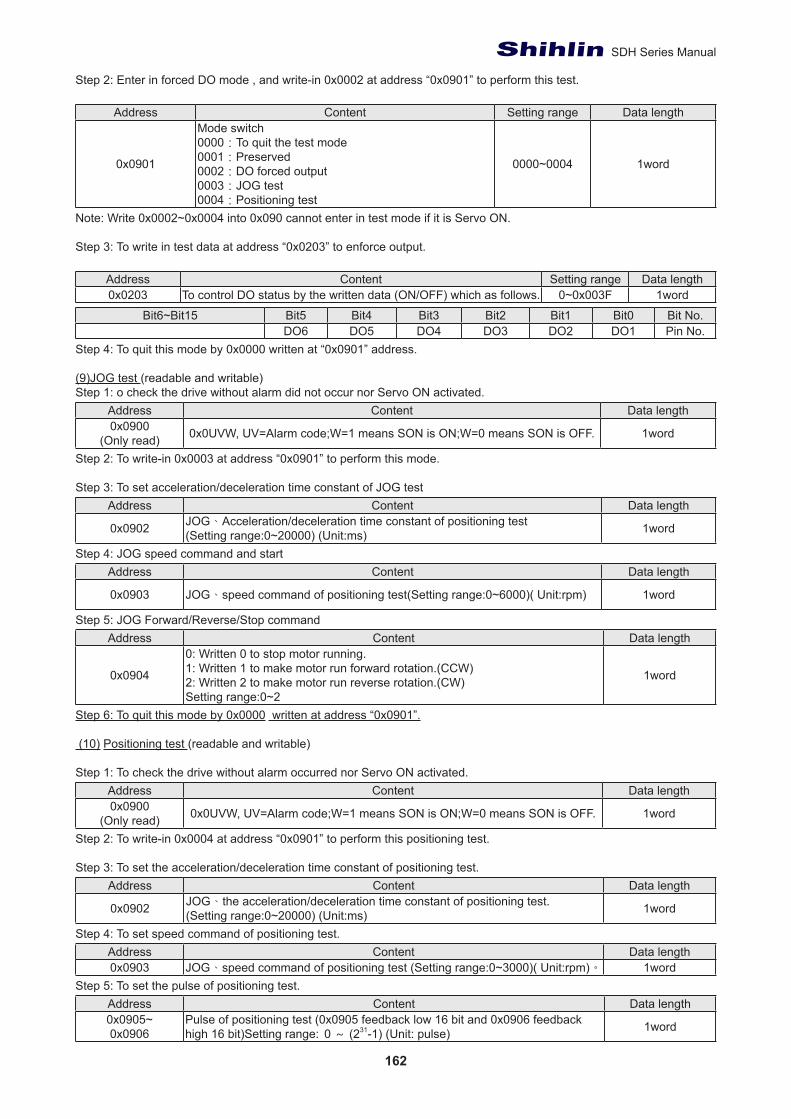
162
SDH Series Manual
Step 2: Enter in forced DO mode , and write-in 0x0002 at address “0x0901” to perform this test.
Address Content Setting range Data length
0x0901
Mode switch0000:To quit the test mode0001:Preserved0002:DO forced output 0003:JOG test0004:Positioning test
0000~0004 1word
Note: Write 0x0002~0x0004 into 0x090 cannot enter in test mode if it is Servo ON.
Step 3: To write in test data at address “0x0203” to enforce output.
Address Content Setting range Data length0x0203 To control DO status by the written data (ON/OFF) which as follows. 0~0x003F 1word
Bit6~Bit15 Bit5 Bit4 Bit3 Bit2 Bit1 Bit0 Bit No.DO6 DO5 DO4 DO3 DO2 DO1 Pin No.
Step 4: To quit this mode by 0x0000 written at “0x0901” address.
(9)JOG test (readable and writable)Step 1: o check the drive without alarm did not occur nor Servo ON activated.
Address Content Data length0x0900
(Only read) 0x0UVW, UV=Alarm code;W=1 means SON is ON;W=0 means SON is OFF. 1word
Step 2: To write-in 0x0003 at address “0x0901” to perform this mode.
Step 3: To set acceleration/deceleration time constant of JOG testAddress Content Data length
0x0902 JOG、Acceleration/deceleration time constant of positioning test(Setting range:0~20000) (Unit:ms) 1word
Step 4: JOG speed command and startAddress Content Data length
0x0903 JOG、speed command of positioning test(Setting range:0~6000)( Unit:rpm) 1word
Step 5: JOG Forward/Reverse/Stop commandAddress Content Data length
0x0904
0: Written 0 to stop motor running.1: Written 1 to make motor run forward rotation.(CCW)2: Written 2 to make motor run reverse rotation.(CW)Setting range:0~2
1word
Step 6: To quit this mode by 0x0000 written at address “0x0901”.
(10) Positioning test (readable and writable)
Step 1: To check the drive without alarm occurred nor Servo ON activated.Address Content Data length0x0900
(Only read) 0x0UVW, UV=Alarm code;W=1 means SON is ON;W=0 means SON is OFF. 1word
Step 2: To write-in 0x0004 at address “0x0901” to perform this positioning test.
Step 3: To set the acceleration/deceleration time constant of positioning test.Address Content Data length
0x0902 JOG、the acceleration/deceleration time constant of positioning test.(Setting range:0~20000) (Unit:ms) 1word
Step 4: To set speed command of positioning test.Address Content Data length0x0903 JOG、speed command of positioning test (Setting range:0~3000)( Unit:rpm)。 1word
Step 5: To set the pulse of positioning test.Address Content Data length0x0905~0x0906
Pulse of positioning test (0x0905 feedback low 16 bit and 0x0906 feedback high 16 bit)Setting range: 0 ~ (231-1) (Unit: pulse) 1word
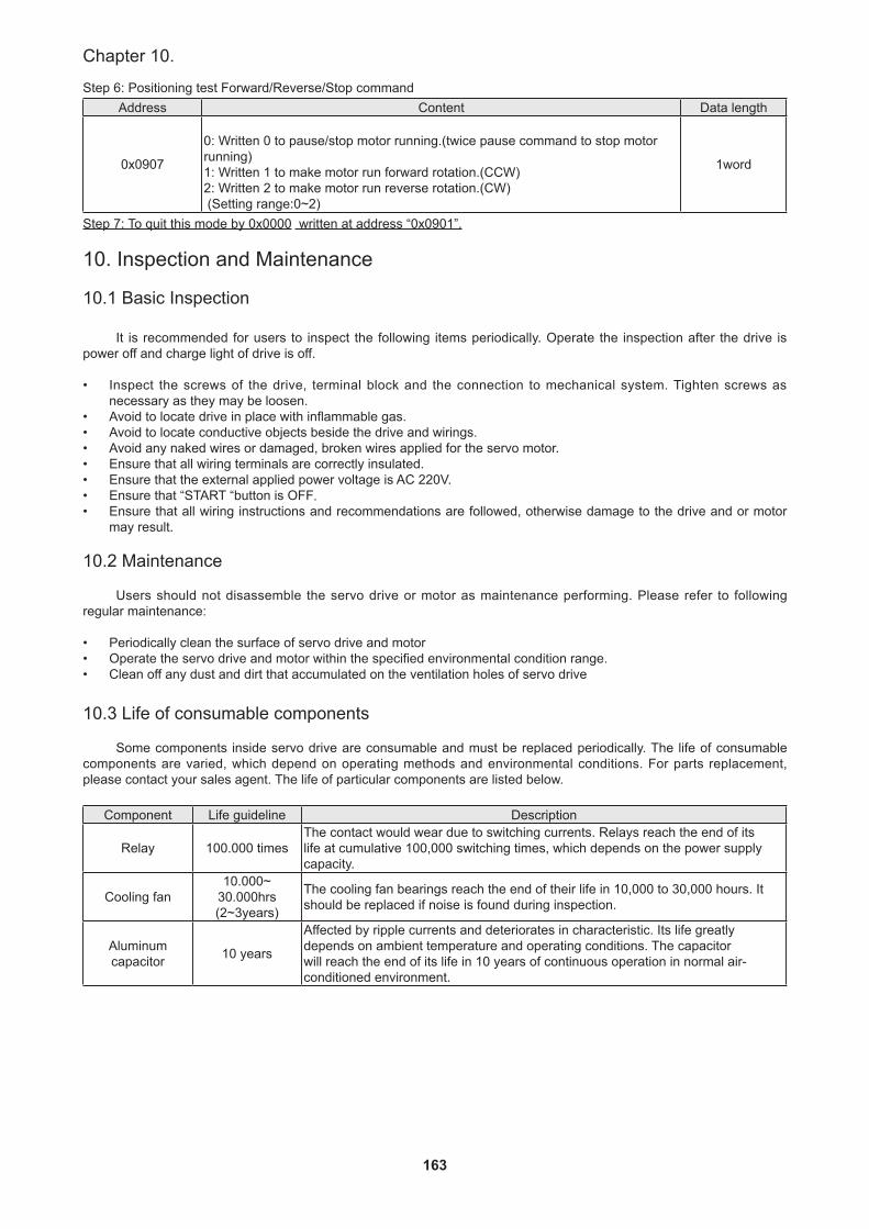
163
Chapter 10.
Step 6: Positioning test Forward/Reverse/Stop commandAddress Content Data length
0x0907
0: Written 0 to pause/stop motor running.(twice pause command to stop motor running) 1: Written 1 to make motor run forward rotation.(CCW)2: Written 2 to make motor run reverse rotation.(CW) (Setting range:0~2)
1word
Step 7: To quit this mode by 0x0000 written at address “0x0901”.
10. Inspection and Maintenance
10.1 Basic Inspection
It is recommended for users to inspect the following items periodically. Operate the inspection after the drive is power off and charge light of drive is off.
• Inspect the screws of the drive, terminal block and the connection to mechanical system. Tighten screws as necessary as they may be loosen.
• Avoid to locate drive in place with inflammable gas.• Avoid to locate conductive objects beside the drive and wirings.• Avoid any naked wires or damaged, broken wires applied for the servo motor.• Ensure that all wiring terminals are correctly insulated.• Ensure that the external applied power voltage is AC 220V.• Ensure that “START “button is OFF.• Ensure that all wiring instructions and recommendations are followed, otherwise damage to the drive and or motor
may result.
10.2 Maintenance
Users should not disassemble the servo drive or motor as maintenance performing. Please refer to following regular maintenance:
• Periodically clean the surface of servo drive and motor• Operate the servo drive and motor within the specified environmental condition range.• Clean off any dust and dirt that accumulated on the ventilation holes of servo drive
10.3 Life of consumable components
Some components inside servo drive are consumable and must be replaced periodically. The life of consumable components are varied, which depend on operating methods and environmental conditions. For parts replacement, please contact your sales agent. The life of particular components are listed below.
Component Life guideline Description
Relay 100.000 timesThe contact would wear due to switching currents. Relays reach the end of its life at cumulative 100,000 switching times, which depends on the power supply capacity.
Cooling fan10.000~
30.000hrs (2~3years)
The cooling fan bearings reach the end of their life in 10,000 to 30,000 hours. It should be replaced if noise is found during inspection.
Aluminum capacitor 10 years
Affected by ripple currents and deteriorates in characteristic. Its life greatly depends on ambient temperature and operating conditions. The capacitor will reach the end of its life in 10 years of continuous operation in normal air-conditioned environment.

164
SDH Series Manual
CAUTION
11. Troubleshooting
An alarm occurs, please make sure that all alarm were cleared to ensure safety then operate. Otherwise it will lead to accidental injury easily..
Caution:
As the following alarms occur, please do not power OFF → ON to clear alarm and start repeatedly, otherwise it will cause damage to the drive or servo motor.Please place the driver aside and let cool off for more than 15 minutes while to clear the following alarms.AL.04(Abnormal regeneration)AL.05(Overload 1)AL.10(Overload 2)
Please place the driver aside and let cool off for more than 30 seconds while to clear the following alarms.AL.03(Over current)
11.1 Alarm list
The drive would display alarm or warning if some faults occurred during operation. As a alarm or a warning occurred, please remedy the fault according to the instruction mentioned in section 11.2 When parameter PD19 is set as □□□1, alarm codes could be output via the ON/OFF states of DO1(CN1_41), DO2(CN1_42), DO5(CN1_45) terminals.
Alarm
Sign Alarm code Name Clear
CN141
CN142
CN145
PowerOFF→ON
Press "SET" on
alarm screen.
RESsignal
AL.01 0 1 0 Over voltage ○AL.02 0 0 1 Low voltage ○ ○ ○AL.03 0 1 1 Over current ○AL.04 0 1 0 Abnormal regeneration ○ ○ ○AL.05 1 0 0 Overload1 ○ ○ ○AL.06 1 0 1 Over speed ○ ○ ○AL.07 1 0 1 Pulse command abnormal ○ ○ ○AL.08 1 0 1 Position error excess ○ ○ ○AL.09 0 0 0 Communication abnormal ○ ○ ○AL.0A 0 0 0 Communication time-out ○ ○ ○AL.0B 1 1 0 Encoder error 1 ○AL.0C 1 1 0 Encoder error 2 ○AL.0D 1 1 0 Fan error ○AL.0E 0 0 0 IGBT overheat ○AL.0F 0 0 0 Memory error ○AL.10 0 0 0 Overload 2 ○AL.11 1 1 1 Motor mismatched ○AL.20 1 1 1 Motor crash error ○AL.21 1 1 1 Motor U/V/W disconnect ○AL.22 1 1 0 Encoder communication error ○AL.23 0 1 0 Full-close position error excess ○ ○ ○AL.24 0 0 0 Encoder mismatched ○AL.25 1 1 0 Linear scale disconnect ○
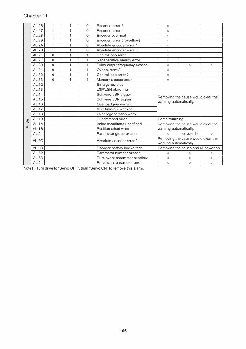
165
Chapter 11.
AL.26 1 1 0 Encoder error 3 ○AL.27 1 1 0 Encoder error 4 ○AL.28 1 1 0 Encoder overheat ○AL.29 1 1 0 Encoder error 5(overflow) ○AL.2A 1 1 0 Absolute encoder error 1 ○AL.2B 1 1 0 Absolute encoder error 2 ○AL.2E 0 1 1 Control loop error ○AL.2F 0 1 1 Regenerative energy error ○AL.30 0 1 1 Pulse output frequency excess ○ ○ ○AL.31 0 1 1 Over current 2 ○AL.32 0 1 1 Control loop error 2 ○AL.33 0 1 1 Memory access error ○
Warn
AL.12 Emergency stop
Removing the cause would clear the warning automatically.
AL.13 LSP/LSN abnormalAL.14 Software LSP triggerAL.15 Software LSN triggerAL.16 Overload pre-warningAL.17 ABS time-out warningAL.18 Over regeneration warnAL.19 Pr command error Home returningAL.1A Index coordinate undefined Removing the cause would clear the
warning automatically.AL.1B Position offset warnAL.61 Parameter group excess ○ ○(Note 1) ○
AL.2C Absolute encoder error 3 Removing the cause would clear the warning automatically.
AL.2D Encoder battery low voltage Removing the cause and re-power on AL.62 Parameter number excess ○ ○ ○AL.63 Pr relevant parameter overflow ○ ○ ○AL.64 Pr relevant parameter error ○ ○ ○
Note1 : Turn drive to “Servo OFF”. than “Servo ON” to remove this alarm.
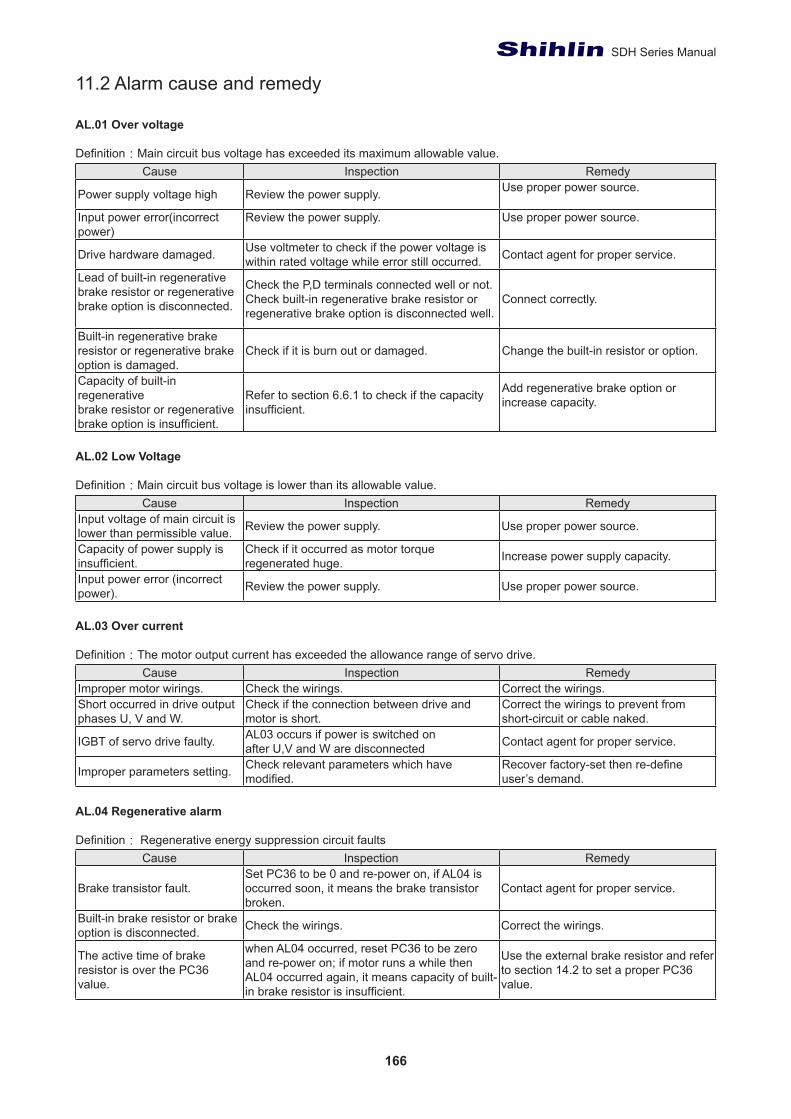
166
SDH Series Manual
11.2 Alarm cause and remedy
AL.01 Over voltage
Definition:Main circuit bus voltage has exceeded its maximum allowable value.Cause Inspection Remedy
Power supply voltage high Review the power supply. Use proper power source.
Input power error(incorrect power)
Review the power supply. Use proper power source.
Drive hardware damaged. Use voltmeter to check if the power voltage is within rated voltage while error still occurred. Contact agent for proper service.
Lead of built-in regenerative brake resistor or regenerative brake option is disconnected.
Check the P,D terminals connected well or not. Check built-in regenerative brake resistor or regenerative brake option is disconnected well.
Connect correctly.
Built-in regenerative brake resistor or regenerative brake option is damaged.
Check if it is burn out or damaged. Change the built-in resistor or option.
Capacity of built-in regenerative brake resistor or regenerative brake option is insufficient.
Refer to section 6.6.1 to check if the capacity insufficient.
Add regenerative brake option or increase capacity.
AL.02 Low Voltage
Definition:Main circuit bus voltage is lower than its allowable value.Cause Inspection Remedy
Input voltage of main circuit is lower than permissible value. Review the power supply. Use proper power source.
Capacity of power supply isinsufficient.
Check if it occurred as motor torqueregenerated huge. Increase power supply capacity.
Input power error (incorrect power). Review the power supply. Use proper power source.
AL.03 Over current
Definition:The motor output current has exceeded the allowance range of servo drive.Cause Inspection Remedy
Improper motor wirings. Check the wirings. Correct the wirings. Short occurred in drive output phases U, V and W.
Check if the connection between drive and motor is short.
Correct the wirings to prevent from short-circuit or cable naked.
IGBT of servo drive faulty. AL03 occurs if power is switched onafter U,V and W are disconnected Contact agent for proper service.
Improper parameters setting. Check relevant parameters which have modified.
Recover factory-set then re-define user’s demand.
AL.04 Regenerative alarm
Definition: Regenerative energy suppression circuit faultsCause Inspection Remedy
Brake transistor fault.Set PC36 to be 0 and re-power on, if AL04 is occurred soon, it means the brake transistor broken.
Contact agent for proper service.
Built-in brake resistor or brake option is disconnected. Check the wirings. Correct the wirings.
The active time of brake resistor is over the PC36 value.
when AL04 occurred, reset PC36 to be zero and re-power on; if motor runs a while then AL04 occurred again, it means capacity of built-in brake resistor is insufficient.
Use the external brake resistor and refer to section 14.2 to set a proper PC36 value.
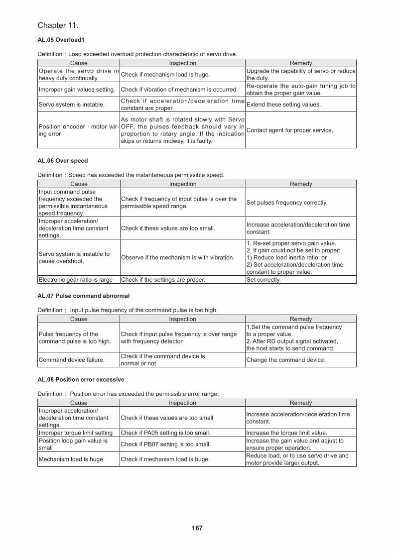
167
Chapter 11.
AL.05 Overload1
Definition:Load exceeded overload protection characteristic of servo drive.Cause Inspection Remedy
Operate the servo drive in heavy duty continually. Check if mechanism load is huge. Upgrade the capability of servo or reduce
the duty.
Improper gain values setting. Check if vibration of mechanism is occurred. Re-operate the auto-gain tuning job to obtain the proper gain value.
Servo system is instable. Check if acceleration/deceleration t ime constant are proper. Extend these setting values.
Position encoder、motor wir-ing error
As motor shaft is rotated slowly with Servo OFF, the pulses feedback should vary in proportion to rotary angle. If the indication skips or returns midway, it is faulty.
Contact agent for proper service.
AL.06 Over speed
Definition:Speed has exceeded the instantaneous permissible speed.Cause Inspection Remedy
Input command pulse frequency exceeded the permissible instantaneous speed frequency.
Check if frequency of input pulse is over the permissible speed range. Set pulses frequency correctly.
Improper acceleration/deceleration time constant settings.
Check if these values are too small. Increase acceleration/deceleration time constant.
Servo system is instable to cause overshoot. Observe if the mechanism is with vibration.
1. Re-set proper servo gain value. 2. If gain could not be set to proper: 1) Reduce load inertia ratio; or 2) Set acceleration/deceleration time constant to proper value.
Electronic gear ratio is large Check if the settings are proper. Set correctly.
AL.07 Pulse command abnormal
Definition: Input pulse frequency of the command pulse is too high.Cause Inspection Remedy
Pulse frequency of the command pulse is too high.
Check if input pulse frequency is over range with frequency detector.
1.Set the command pulse frequencyto a proper value.2. After RD output signal activated,the host starts to send command.
Command device failure. Check if the command device isnormal or not. Change the command device.
AL.08 Position error excessive
Definition: Position error has exceeded the permissible error range.Cause Inspection Remedy
Improper acceleration/deceleration time constant settings.
Check if these values are too small Increase acceleration/deceleration time constant.
Improper torque limit setting Check if PA05 setting is too small. Increase the torque limit value. Position loop gain value is small Check if PB07 setting is too small. Increase the gain value and adjust to
ensure proper operation.
Mechanism load is huge. Check if mechanism load is huge. Reduce load, or to use servo drive and motor provide larger output.
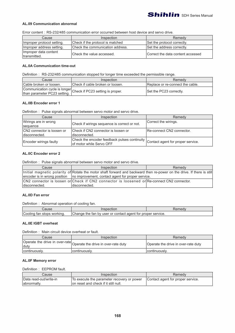
168
SDH Series Manual
AL.09 Communication abnormal Error content:RS-232/485 communication error occurred between host device and servo drive.
Cause Inspection RemedyImproper protocol setting. Check if the protocol is matched Set the protocol correctly. Improper address setting. Check the communication address. Set the address correctly. Improper data content transmitted. Check the value accessed. Correct the data content accessed
AL.0A Communication time-out
Definition: RS-232/485 communication stopped for longer time exceeded the permissible range.Cause Inspection Remedy
Cable broken or loosen. Check if cable broken or loosen. Replace or re-connect the cable. Communication cycle is longer than parameter PC23 setting. Check if PC23 setting is proper. Set the PC23 correctly.
AL.0B Encoder error 1
Definition: Pulse signals abnormal between servo motor and servo drive.Cause Inspection Remedy
Wirings are in wrong sequence Check if wirings sequence is correct or not. Correct the wirings.
CN2 connector is loosen ordisconnected.
Check if CN2 connector is loosen ordisconnected.
Re-connect CN2 connector.
Encoder wirings faulty Check the encoder feedback pulses continuity of motor while Servo OFF Contact agent for proper service.
AL.0C Encoder error 2
Definition: Pulse signals abnormal between servo motor and servo drive.Cause Inspection Remedy
Initial magnetic polarity of encoder is in wrong position
Rotate the motor shaft forward and backward then re-power on the drive. If there is still no improvement, contact agent for proper service.
CN2 connector is loosen or disconnected.
Check if CN2 connector is loosened or disconnected.
Re-connect CN2 connector.
AL.0D Fan error
Definition: Abnormal operation of cooling fan.Cause Inspection Remedy
Cooling fan stops working. Change the fan by user or contact agent for proper service.
AL.0E IGBT overheat
Definition: Main circuit device overheat or fault.Cause Inspection Remedy
Operate the drive in over-rate duty Operate the drive in over-rate duty Operate the drive in over-rate duty
continuously. continuously. continuously.
AL.0F Memory error
Definition: EEPROM fault.Cause Inspection Remedy
Data read-out/write-in abnormally.
To execute the parameter recovery or power on reset and check if it still null.
Contact agent for proper service.
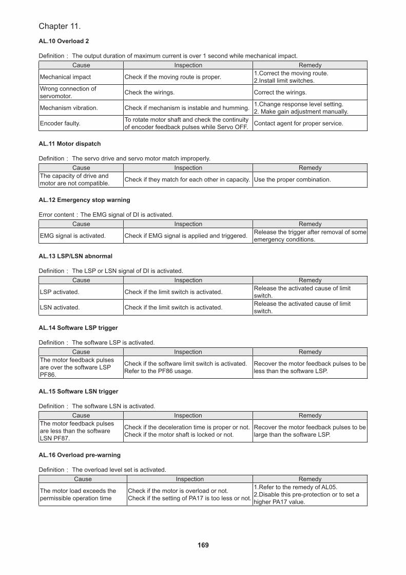
169
Chapter 11.
AL.10 Overload 2
Definition: The output duration of maximum current is over 1 second while mechanical impact.Cause Inspection Remedy
Mechanical impact Check if the moving route is proper. 1.Correct the moving route. 2.Install limit switches.
Wrong connection of servomotor. Check the wirings. Correct the wirings.
Mechanism vibration. Check if mechanism is instable and humming. 1.Change response level setting. 2. Make gain adjustment manually.
Encoder faulty. To rotate motor shaft and check the continuity of encoder feedback pulses while Servo OFF. Contact agent for proper service.
AL.11 Motor dispatch
Definition: The servo drive and servo motor match improperly.Cause Inspection Remedy
The capacity of drive and motor are not compatible. Check if they match for each other in capacity. Use the proper combination.
AL.12 Emergency stop warning
Error content:The EMG signal of DI is activated.Cause Inspection Remedy
EMG signal is activated. Check if EMG signal is applied and triggered. Release the trigger after removal of some emergency conditions.
AL.13 LSP/LSN abnormal
Definition: The LSP or LSN signal of DI is activated.Cause Inspection Remedy
LSP activated. Check if the limit switch is activated. Release the activated cause of limit switch.
LSN activated. Check if the limit switch is activated. Release the activated cause of limit switch.
AL.14 Software LSP trigger
Definition: The software LSP is activated.Cause Inspection Remedy
The motor feedback pulses are over the software LSP PF86.
Check if the software limit switch is activated. Refer to the PF86 usage.
Recover the motor feedback pulses to be less than the software LSP.
AL.15 Software LSN trigger
Definition: The software LSN is activated.Cause Inspection Remedy
The motor feedback pulses are less than the softwareLSN PF87.
Check if the deceleration time is proper or not. Check if the motor shaft is locked or not.
Recover the motor feedback pulses to be large than the software LSP.
AL.16 Overload pre-warning
Definition: The overload level set is activated.Cause Inspection Remedy
The motor load exceeds the permissible operation time
Check if the motor is overload or not.Check if the setting of PA17 is too less or not.
1.Refer to the remedy of AL05.2.Disable this pre-protection or to set a higher PA17 value.

170
SDH Series Manual
AL.17 ABS time-out warning
Cause Inspection Remedy
The absolute position signal exceeds the time limit.
Delta DIO Communication: Check if when the drive data is ready (ABSR), the upper PC is no signal required more than five seconds (ABSQ) in absolute position communication situation.Mitsubishi DIO Communication:please refer to section 14.1.5 (Output error)。
Turn ABSE or ABSM signal terminal OFF and check if the upper PC communication format is correct or not.
AL.19 PR command error
Cause Inspection Remedy
Positioning command register overflows.
Incremental system:PR mode continuously operates in one direction and causes feedback register overflows. And the coordinate system cannot reflect the correct position. If issuing the absolute positioning command (except incremental) at this time, the error will occur.Absolute system:This error will occur in following situations:1. The position feedback register is overflow2.Change the electronic gear ratio(PA06、PA07) and homing procedure has not been executed.3.Operate Absolute Positioning Command when DO HOME is OFF.
Conduct homing procedure.
AL.20 Motor Crash Error
Cause Inspection Remedy
When effectiveness loading rate reaches setting value of PA15 and exceeds the time set by PA16.
1. Check if PA15 is enabled.2. Check if PA15 is set too small and the time of PA16 is set too short.
1. If it is enabled by mistake, please set PA15 to zero.2. According to the actual torque setting, if the value is set too small, it will lose the function of protection.
AL.21 Incorrect wiring of the motor power line U, V, W
Cause Inspection RemedyShort occurred in servo motor power (U, V, W)
Check if U, V, W of the motor is incorrect con-nected.
Follow the user manual to correct the wiring.
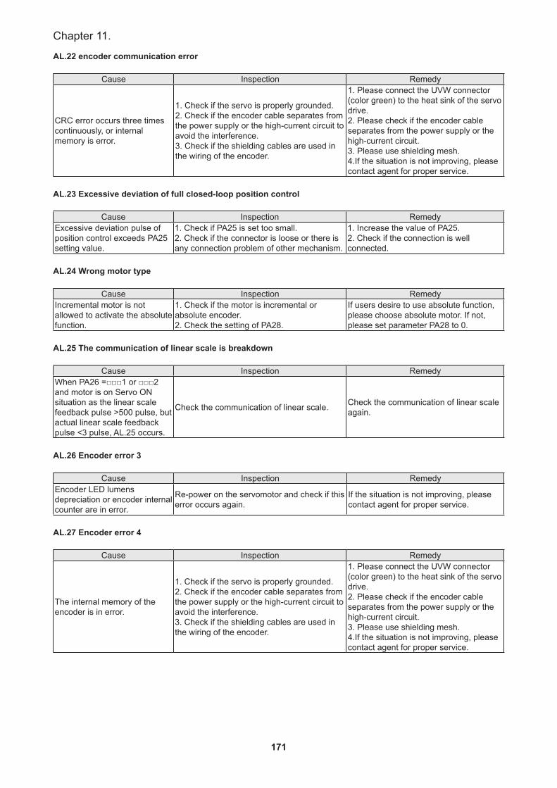
171
Chapter 11.
AL.22 encoder communication error
Cause Inspection Remedy
CRC error occurs three times continuously, or internal memory is error.
1. Check if the servo is properly grounded.2. Check if the encoder cable separates from the power supply or the high-current circuit to avoid the interference.3. Check if the shielding cables are used in the wiring of the encoder.
1. Please connect the UVW connector (color green) to the heat sink of the servo drive.2. Please check if the encoder cable separates from the power supply or the high-current circuit.3. Please use shielding mesh.4.If the situation is not improving, please contact agent for proper service.
AL.23 Excessive deviation of full closed-loop position control
Cause Inspection RemedyExcessive deviation pulse of position control exceeds PA25 setting value.
1. Check if PA25 is set too small.2. Check if the connector is loose or there is any connection problem of other mechanism.
1. Increase the value of PA25.2. Check if the connection is well connected.
AL.24 Wrong motor type
Cause Inspection RemedyIncremental motor is not allowed to activate the absolute function.
1. Check if the motor is incremental or absolute encoder.2. Check the setting of PA28.
If users desire to use absolute function, please choose absolute motor. If not, please set parameter PA28 to 0.
AL.25 The communication of linear scale is breakdown
Cause Inspection RemedyWhen PA26 =□□□1 or □□□2 and motor is on Servo ON situation as the linear scale feedback pulse >500 pulse, but actual linear scale feedback pulse <3 pulse, AL.25 occurs.
Check the communication of linear scale. Check the communication of linear scale again.
AL.26 Encoder error 3
Cause Inspection RemedyEncoder LED lumens depreciation or encoder internal counter are in error.
Re-power on the servomotor and check if this error occurs again.
If the situation is not improving, please contact agent for proper service.
AL.27 Encoder error 4
Cause Inspection Remedy
The internal memory of the encoder is in error.
1. Check if the servo is properly grounded.2. Check if the encoder cable separates from the power supply or the high-current circuit to avoid the interference.3. Check if the shielding cables are used in the wiring of the encoder.
1. Please connect the UVW connector (color green) to the heat sink of the servo drive.2. Please check if the encoder cable separates from the power supply or the high-current circuit.3. Please use shielding mesh.4.If the situation is not improving, please contact agent for proper service.

172
SDH Series Manual
AL.28 Encoder overheat
Cause Inspection Remedy
Encoder operating temperature is over 95 ℃ .
Check the encoder is not in high temperature environment or close to the heat.
1.To avoid high temperature environment and lower the temperature of the encoder. 2. If the situation is not improving, please contact agent for proper service.
AL.29 Encoder error 5
Cause Inspection Remedy
The multi-turn of absolute encoder exceeds the range.
Check if the multi-turn of absolute encoder exceeds the maximum range: -32768 ~ +32767
Conduct homing procedure. Please refer to the description of absolute coordinate initialization in Chapter 14.
AL.2A Absolute encoder error 1
Cause Inspection Remedy
The voltage of the absolute encoder battery is lower than the specification.
Check if the voltage of the battery is lower than 2.45V(TYP).
After changing the battery, please conduct homing procedure. Please refer to the description of absolute coordinate initialization in Chapter 14.
Battery circuit disconnects or wire broken.
1.Check the wiring of the encoder.2.Check the wiring between the battery pack and power cable of the servo drive.
After connecting battery to encoder correctly or repairing wiring, conduct homing procedure. Please refer to the description of absolute coordinate initialization in Chapter 14.
AL.2B absolute encoder error 2
Cause Inspection RemedyThe value of absolute encoder multi-revolution counter is abnormal.
Re-power on the servomotor and check if this error occurs again.
If the situation is not improving, please contact agent for proper service.
AL.2C absolute encoder error 3b
Cause Inspection RemedyChange the battery when the power is OFF which is controlled by the servo drive.
Do not change or remove the battery power when the power is OFF which is controlled by the servo drive.
Conduct homing procedure. Please refer to the description of absolute coordinate initialization in Chapter 14.
Start up with absolute function and not have finished absolute coordinate initialization.
1.Install the battery.2.Check the wiring between the battery pack and power cable of the servo drive.3.Check the wiring of the encoder.
Conduct homing procedure. Please refer to the description of absolute coordinate initialization in Chapter 14.
AL.2D encoder battery under voltage
Cause Inspection Remedy
The voltage of the encoder is lower than the specification.
1. Check if the voltage of the battery on the panel is lower than 3.0V(TPY).2. Check if the voltage of the battery is lower than 3.0V(TPY).
Change the battery when power is ON which is controlled by the servo drive. After changing the battery, AL. 2D will be cleared automatically.
AL.2E Control circuit error
Cause Inspection RemedyWhen motor is running and external loading is bigger, the situation of servo ON (SON) OFF becomes ON instantly.
Check if servo ON (SON) turns on. Turn on servo ON (SON) correctly.
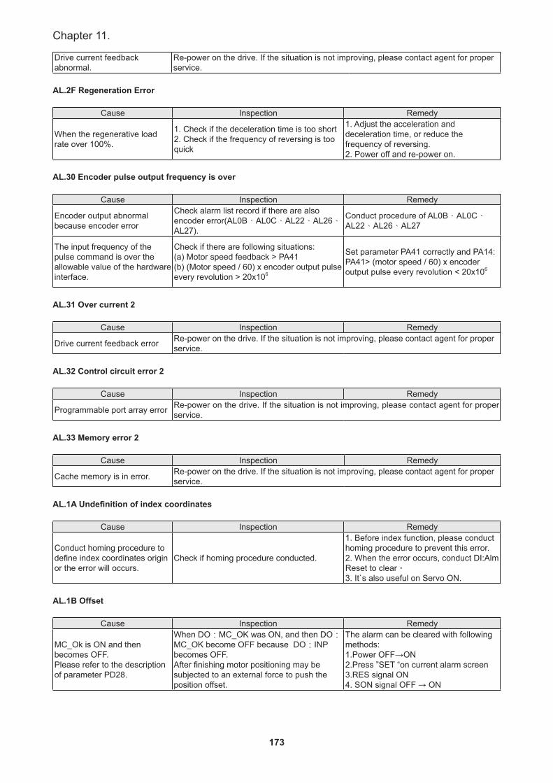
173
Chapter 11.
Drive current feedback abnormal.
Re-power on the drive. If the situation is not improving, please contact agent for proper service.
AL.2F Regeneration Error
Cause Inspection Remedy
When the regenerative load rate over 100%.
1. Check if the deceleration time is too short 2. Check if the frequency of reversing is too quick
1. Adjust the acceleration and deceleration time, or reduce the frequency of reversing.2. Power off and re-power on.
AL.30 Encoder pulse output frequency is over
Cause Inspection Remedy
Encoder output abnormal because encoder error
Check alarm list record if there are also encoder error(AL0B、AL0C、AL22、AL26、AL27).
Conduct procedure of AL0B、AL0C、AL22、AL26、AL27
The input frequency of the pulse command is over the allowable value of the hardware interface.
Check if there are following situations:(a) Motor speed feedback > PA41(b) (Motor speed / 60) x encoder output pulse every revolution > 20x106
Set parameter PA41 correctly and PA14: PA41> (motor speed / 60) x encoder output pulse every revolution < 20x106
AL.31 Over current 2
Cause Inspection Remedy
Drive current feedback error Re-power on the drive. If the situation is not improving, please contact agent for proper service.
AL.32 Control circuit error 2
Cause Inspection Remedy
Programmable port array error Re-power on the drive. If the situation is not improving, please contact agent for proper service.
AL.33 Memory error 2
Cause Inspection Remedy
Cache memory is in error. Re-power on the drive. If the situation is not improving, please contact agent for proper service.
AL.1A Undefinition of index coordinates
Cause Inspection Remedy
Conduct homing procedure to define index coordinates origin or the error will occurs.
Check if homing procedure conducted.
1. Before index function, please conduct homing procedure to prevent this error. 2. When the error occurs, conduct DI:Alm Reset to clear。3. It`s also useful on Servo ON.
AL.1B Offset
Cause Inspection Remedy
MC_Ok is ON and then becomes OFF.Please refer to the description of parameter PD28.
When DO:MC_OK was ON, and then DO:MC_OK become OFF because DO:INP becomes OFF.After finishing motor positioning may be subjected to an external force to push the position offset.
The alarm can be cleared with following methods:1.Power OFF→ON2.Press ”SET “on current alarm screen3.RES signal ON 4. SON signal OFF → ON
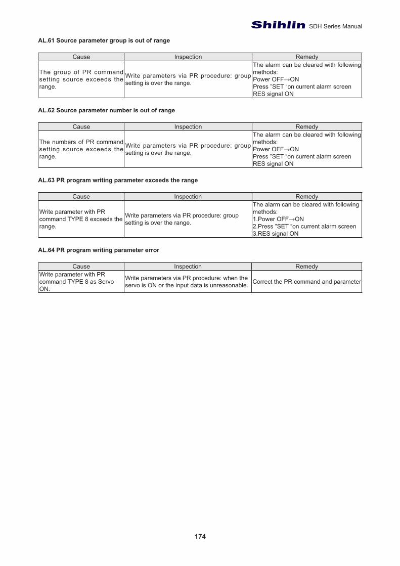
174
SDH Series Manual
AL.61 Source parameter group is out of range
Cause Inspection Remedy
The group of PR command setting source exceeds the range.
Write parameters via PR procedure: group setting is over the range.
The alarm can be cleared with following methods:Power OFF→ONPress ”SET “on current alarm screenRES signal ON
AL.62 Source parameter number is out of range
Cause Inspection Remedy
The numbers of PR command setting source exceeds the range.
Write parameters via PR procedure: group setting is over the range.
The alarm can be cleared with following methods:Power OFF→ONPress ”SET “on current alarm screenRES signal ON
AL.63 PR program writing parameter exceeds the range
Cause Inspection Remedy
Write parameter with PR command TYPE 8 exceeds the range.
Write parameters via PR procedure: group setting is over the range.
The alarm can be cleared with following methods:1.Power OFF→ON2.Press ”SET “on current alarm screen3.RES signal ON
AL.64 PR program writing parameter error
Cause Inspection RemedyWrite parameter with PR command TYPE 8 as Servo ON.
Write parameters via PR procedure: when the servo is ON or the input data is unreasonable. Correct the PR command and parameter
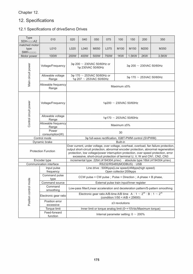
175
Chapter 12.
12. Specifications
12.1 Specifications of driveServo Drives
TypeSDH-□□□A2 010 020 040 050 075 100 150 200 350
matched motor type
SMH-□□□□L010 L020 L040 M050 L075 M100 M150 M200 M350
Motor power 100W 200W 400W 500W 750W 1KW 1.5KW 2KW 3.5KW
Mai
n ci
rcui
t pow
er Voltage/Frequency 3φ 200 〜 230VAC 50/60Hz or1φ 230VAC 50/60Hz 3φ 200 〜 230VAC 50/60Hz
Allowable voltage Range
3φ 170 〜 253VAC 50/60Hz or1φ 207 〜 253VAC 50/60Hz 3φ 170 〜 253VAC 50/60Hz
Allowable frequency Range Maximum ±5%
Con
trol c
ircui
t pow
er Voltage/Frequency 1φ200 〜 230VAC 50/60Hz
Allowable voltage Range 1φ170 〜 253VAC 50/60Hz
Allowable frequency Range Maximum ±5%
Power consumption(W) 30
Control mode 3φ full-wave rectification, IGBT-PWM control (SVPWM)Dynamic brake Built-in
Protection Function
Over current, under voltage, over voltage, overheat, overload, fan failure protection, output short-circuit protection, abnormal encoder protection, abnormal regeneration protection, low voltage/power interruption protection, over speed protection, error
excessive, short-circuit protection of terminal U, V, W and CN1, CN2, CN3Encoder type incremental type: 22bit (4194304 p/rev) ,absolute type:16bit (4194304 p/rev)
Communication interface RS232/RS485(MODBUS)、USB
Pos
ition
con
trol m
ode
Input pulse frequency
Line drive : 500Kpps(Low speed)/4Mpps(high speed)Open collector:200kpps
Command pulse type CCW pulse + CW pulse;Pulse + Direction;A phase + B phase,
Command source External pulse train input/Inner registerCommand smoothing Low-pass filter/Linear acceleration and deceleration pattern/S-pattern smoothing
Electronic gear ratio Electronic gear ratio A/B-time A/B time A:1 〜 226、B:1 〜 226
(condition:1/50 < A/B < 25600)Position error
excessive ±3 revolutions
Torque limit Inner limit or torque analog limit (0~+10Vdc/Maximum torque)Feed-forward
function Internal parameter setting: 0 〜 200%
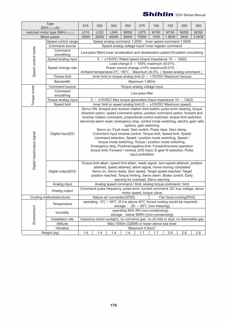
176
SDH Series Manual
TypeSDH-□□□A2 010 020 040 050 075 100 150 200 350
matched motor type SMH-□□□□ L010 L020 L040 M050 L075 M100 M150 M200 M350Motor power 100W 200W 400W 500W 750W 1KW 1.5KW 2KW 3.5KW
Spe
ed c
ontro
l mod
e
Speed control range Speed analog command 1:2000、Inner speed command 1:5000Command source Speed analog voltage input/ Inner register command
Command smoothing Low-pass filter/Linear acceleration and deceleration pattern/S-pattern smoothing
Speed analog input 0 ~ ±10VDC/ Rated speed ((Input impedance 10 ~ 12kΩ)
Speed change rateLoad change 0 ~ 100% maximum ±0.01%
Power source change ±10% maximum0.01%,Ambient temperature 0℃ ~55℃:Maximum ±0.5% (Speed analog command)
Torque limit Inner limit or torque analog limit (0 ~ +10VDC/ Maximum torque)Bandwidth Maximum 1.6KHz
Torq
ue m
ode Command source Torque analog voltage input
Command smoothing Low-pass filter
Torque analog input 0 ~ ±10VDC/ Max torque generated (Input impedance 10 ~ 12kΩ) Speed limit Inner limit or speed analog limit (0 ~ ±10VDC/ Maximum speed)
Dig
ital i
nput
/out
put s
igna
l
Digital input(DI)
Servo ON, forward and reverse rotation limit switch, pulse error clearing, torque direction option, speed command option, position command option, forward and reverse rotation command, proportional control switched, torque limit switched,
abnormal alarm reset, emergency stop, control mode switching, electric gear ratio options, gain switching
Servo on, Fault reset, Gain switch, Pulse clear, Zero clamp,Command input reverse control, Torque limit, Speed limit, Speedcommand selection, Speed / position mode switching, Speed /
torque mode switching, Torque / position mode switching,Emergency stop, Positive/negative limit, Forward/reverse operationtorque limit, Forward / reverse JOG input, E-gear N selection, Pulse
input prohibition
Digital output(DO)
Torque limit attain, speed limit attain, ready signal, zero speed attained, position attained, speed attained, alarm signal, home moving completed
Servo on, Servo ready, Zero speed, Target speed reached, Targetposition reached, Torque limiting, Servo alarm, Brake control, Early
warning for overload, Servo warningAnalog input Analog speed command / limit, analog torque command / limit
Analog output Command pulse frequency, pulse error, current command, DC bus voltage, serve motor speed, torque value
Cooling method(structure) Nature air convention(IP20) Fan force-cooling(IP20)
Env
ironm
ent Temperature operating : 0℃ ~ 55℃ (If it is above 45℃ forced cooling would be required)、
storage: -20 ~ 65℃ (non-freezing)
Humidity operating 90% RH (non-condensing)、storage:below 90RH ((non-condensing)
Installation site Indoor(no direct sunlight), no corrosive gas, no oil mist or dust, no flammable gasAltitude Max.1000m (3280ft) or lower above sea level
Vibration Maximum 5.9m/s2
Weight (kg) 1.4 1.4 1.4 1.4 1.7 1.7 2.6 2.6 2.6
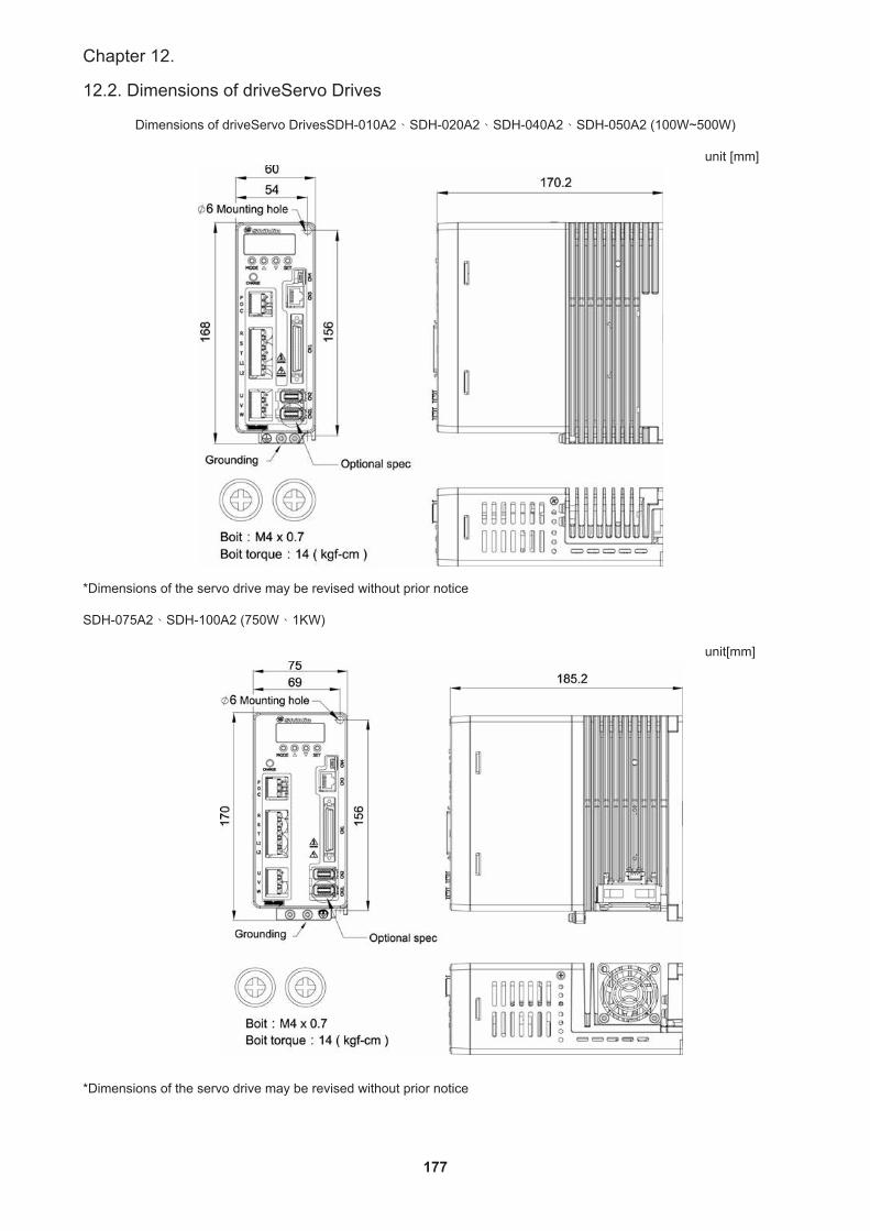
177
Chapter 12.
12.2. Dimensions of driveServo Drives
Dimensions of driveServo DrivesSDH-010A2、SDH-020A2、SDH-040A2、SDH-050A2 (100W~500W)
unit [mm]
*Dimensions of the servo drive may be revised without prior notice
SDH-075A2、SDH-100A2 (750W、1KW)
unit[mm]
*Dimensions of the servo drive may be revised without prior notice
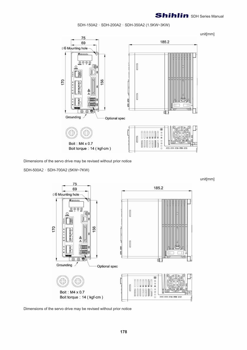
178
SDH Series Manual
SDH-150A2、SDH-200A2、SDH-350A2 (1.5KW~3KW)
unit[mm]
Dimensions of the servo drive may be revised without prior notice
SDH-500A2、SDH-700A2 (5KW~7KW)
unit[mm]
Dimensions of the servo drive may be revised without prior notice
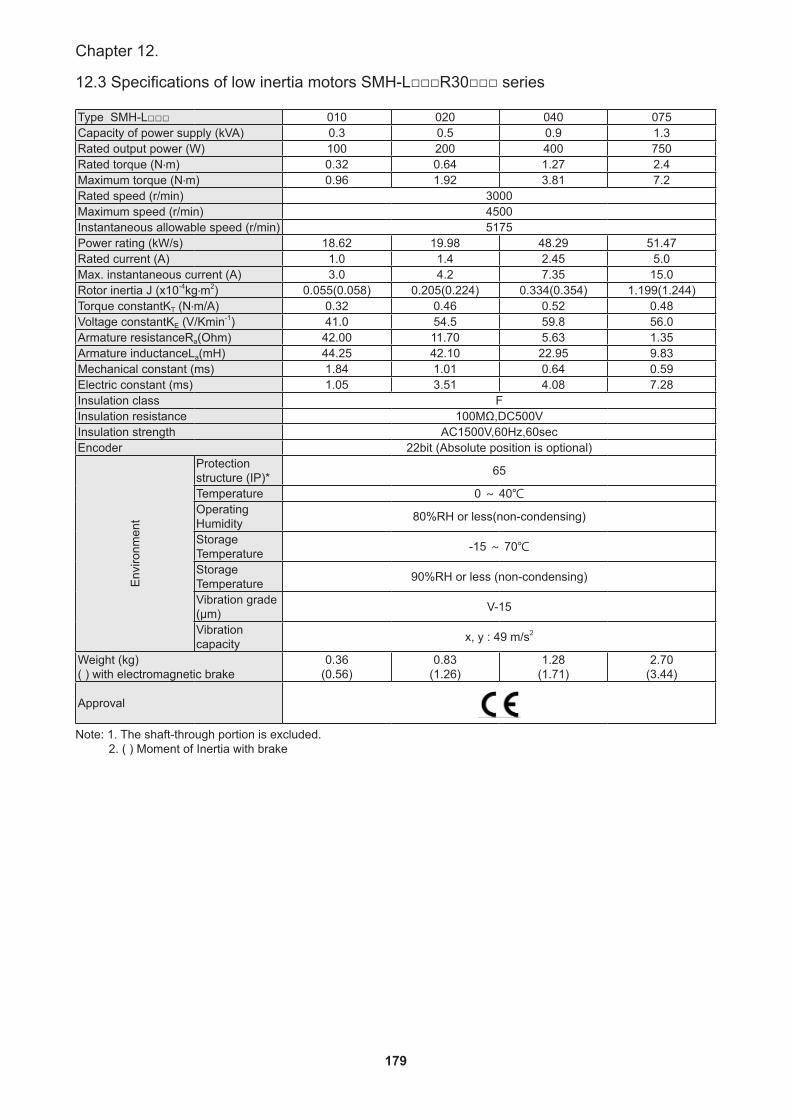
179
Chapter 12.
12.3 Specifications of low inertia motors SMH-L□□□ ••R30□□□ series
Type SMH-L□□□ 010 020 040 075Capacity of power supply (kVA) 0.3 0.5 0.9 1.3Rated output power (W) 100 200 400 750Rated torque (N‧m) 0.32 0.64 1.27 2.4Maximum torque (N‧m) 0.96 1.92 3.81 7.2Rated speed (r/min) 3000Maximum speed (r/min) 4500Instantaneous allowable speed (r/min) 5175Power rating (kW/s) 18.62 19.98 48.29 51.47Rated current (A) 1.0 1.4 2.45 5.0Max. instantaneous current (A) 3.0 4.2 7.35 15.0Rotor inertia J (x10-4kg‧m2) 0.055(0.058) 0.205(0.224) 0.334(0.354) 1.199(1.244)Torque constantKT (N‧m/A) 0.32 0.46 0.52 0.48Voltage constantKE (V/Kmin-1) 41.0 54.5 59.8 56.0Armature resistanceRa(Ohm) 42.00 11.70 5.63 1.35Armature inductanceLa(mH) 44.25 42.10 22.95 9.83Mechanical constant (ms) 1.84 1.01 0.64 0.59Electric constant (ms) 1.05 3.51 4.08 7.28Insulation class FInsulation resistance 100MΩ,DC500VInsulation strength AC1500V,60Hz,60secEncoder 22bit (Absolute position is optional)
Env
ironm
ent
Protection structure (IP)* 65
Temperature 0 ~ 40℃Operating Humidity 80%RH or less(non-condensing)
Storage Temperature -15 ~ 70℃
Storage Temperature 90%RH or less (non-condensing)
Vibration grade (μm) V-15
Vibration capacity x, y : 49 m/s2
Weight (kg) ( ) with electromagnetic brake
0.36(0.56)
0.83(1.26)
1.28(1.71)
2.70(3.44)
Approval
Note: 1. The shaft-through portion is excluded. 2. ( ) Moment of Inertia with brake
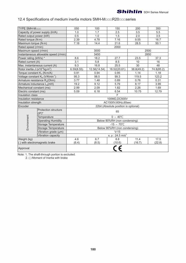
180
SDH Series Manual
12.4 Specifications of medium inertia motors SMH-M□□□R20□□□series
TYPE SMH-M□□□ 050 100 150 200 350Capacity of power supply (kVA) 1.0 1.7 2.5 3.5 5.5Rated output power (kW) 0.5 1.0 1.5 2.0 3.5Rated torque (N‧m) 2.39 4.78 7.16 9.55 16.7Maximum torque (N‧m) 7.16 14.4 21.6 28.5 50.1Rated speed (r/min) 2000Maximum speed (r/min) 3000 2500Instantaneous allowable speed (r/min) 3450 2850Power rating (kW/s) * 8.6 18.2 27.7 23.5 37.3Rated current (A) 3.1 5.8 8.5 10 16Max. instantaneous current (A) 9.3 16.8 25.5 30 48Rotor inertia J (x10-4kg‧m2) 6.59(8.55) 12.56(14.54) 18.52(20.61) 38.8(49.2) 74.8(85.2)Torque constant KT (N‧m/A) 0.91 0.94 0.95 1.14 1.18Voltage constant KE (V/Kmin-1) 95.3 98.5 99.3 119.5 123.2Armature resistance Ra(Ohm) 3.77 1.48 0.89 0.76 0.31Armature inductance La(mH) 19.2 9.12 5.79 8.17 3.99Mechanical constant (ms) 2.99 2.09 1.82 2.26 1.69Electric constant (ms) 5.09 6.18 6.54 10.75 12.79Insulation class FInsulation resistance 100MΩ,DC500VInsulation strength AC1500V,60Hz,60secEncoder 22bit (Absolute position is optional)
Env
ironm
ent
Protection structure (IP)* 65
Temperature 0 ~ 40℃Operating Humidity Below 80%RH (non condensing)Storage Temperature -15 ~ 70℃Storage Temperature Below 90%RH (non condensing)Vibration grade (μm) V-15Vibration capacity x, y : 24.5 m/s2
Weight (kg) ( ) with electromagnetic brake
4.6(6.4)
6.7(8.5)
8.8(10.6)
11.4(16.7)
17.5(22.8)
Approval
Note: 1. The shaft-through portion is excluded. 2. ( ) Moment of Inertia with brake
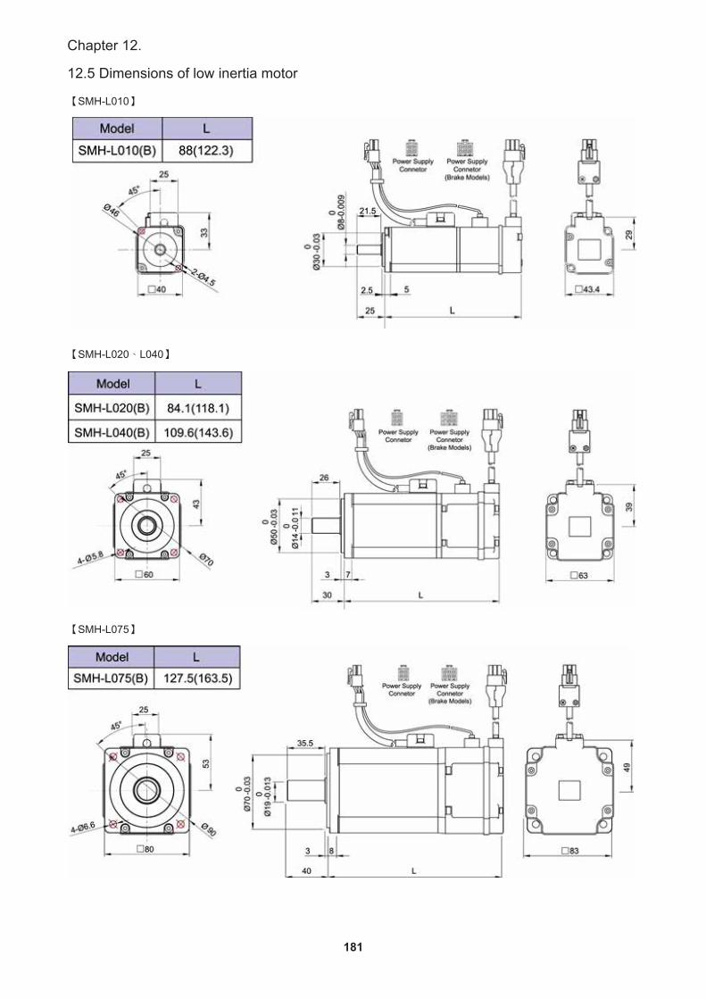
181
Chapter 12.
12.5 Dimensions of low inertia motor
【SMH-L010】
【SMH-L020、L040】
【SMH-L075】
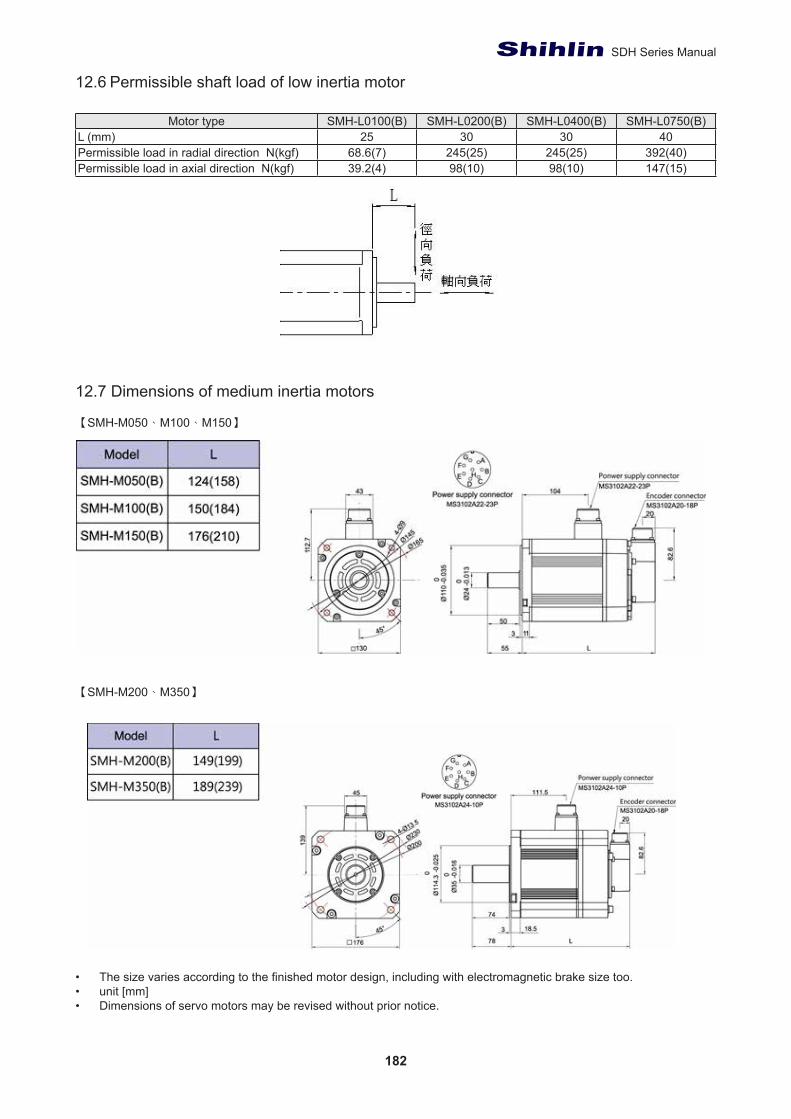
182
SDH Series Manual
12.6 Permissible shaft load of low inertia motor
Motor type SMH-L0100(B) SMH-L0200(B) SMH-L0400(B) SMH-L0750(B)L (mm) 25 30 30 40Permissible load in radial direction N(kgf) 68.6(7) 245(25) 245(25) 392(40)Permissible load in axial direction N(kgf) 39.2(4) 98(10) 98(10) 147(15)
12.7 Dimensions of medium inertia motors
【SMH-M050、M100、M150】
【SMH-M200、M350】
• The size varies according to the finished motor design, including with electromagnetic brake size too.• unit [mm]• Dimensions of servo motors may be revised without prior notice.
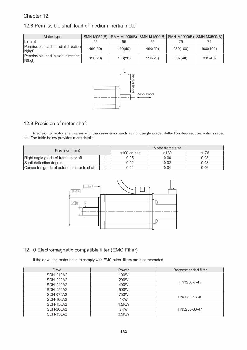
183
Chapter 12.
12.8 Permissible shaft load of medium inertia motor
Motor type SMH-M050(B) SMH-M1000(B) SMH-M1500(B) SMH-M2000(B) SMH-M3500(B)L (mm) 55 55 55 79 79Permissible load in radial direction N(kgf) 490(50) 490(50) 490(50) 980(100) 980(100)
Permissible load in axial direction N(kgf) 196(20) 196(20) 196(20) 392(40) 392(40)
12.9 Precision of motor shaft
Precision of motor shaft varies with the dimensions such as right angle grade, deflection degree, concentric grade, etc. The table below provides more details.
Precision (mm) Motor frame size□100 or less □130 □176
Right angle grade of frame to shaft a 0.05 0.06 0.08Shaft deflection degree b 0.02 0.02 0.03Concentric grade of outer diameter to shaft c 0.04 0.04 0.06
12.10 Electromagnetic compatible filter (EMC Filter)
If the drive and motor need to comply with EMC rules, filters are recommended.
Drive Power Recommended filterSDH-010A2 100W
FN3258-7-45SDH-020A2 200WSDH-040A2 400WSDH-050A2 500WSDH-075A2 750W FN3258-16-45SDH-100A2 1KWSDH-150A2 1.5KW
FN3258-30-47SDH-200A2 2KWSDH-350A2 3.5KW
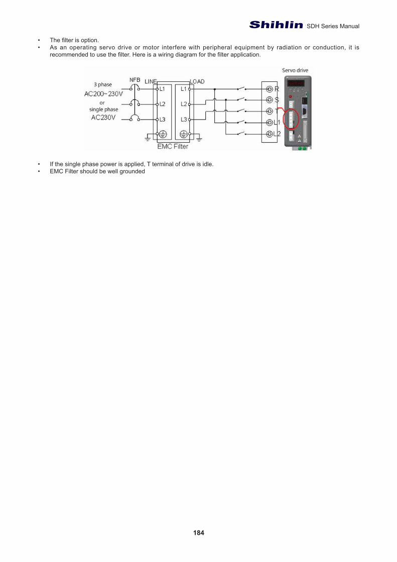
184
SDH Series Manual
• The filter is option.• As an operating servo drive or motor interfere with peripheral equipment by radiation or conduction, it is
recommended to use the filter. Here is a wiring diagram for the filter application.
• If the single phase power is applied, T terminal of drive is idle. • EMC Filter should be well grounded
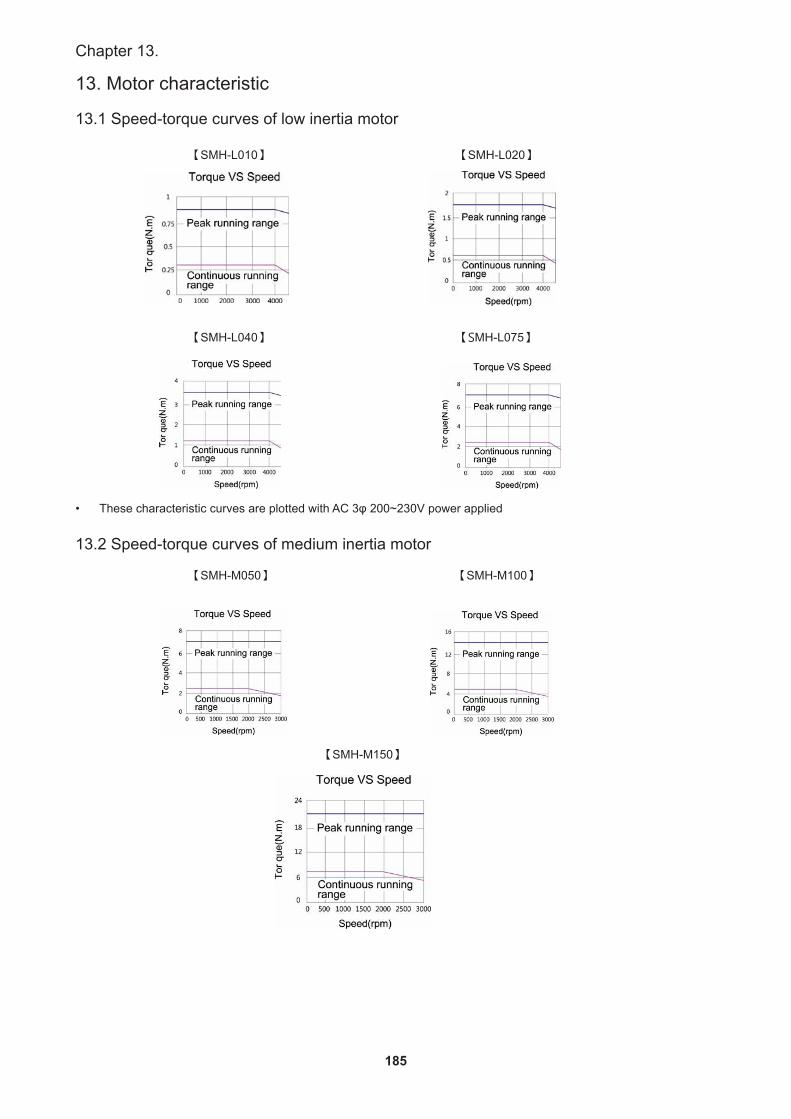
185
Chapter 13.
13. Motor characteristic
13.1 Speed-torque curves of low inertia motor
【SMH-L010】 【SMH-L020】
【SMH-L040】 【SMH-L075】
• These characteristic curves are plotted with AC 3φ 200~230V power applied
13.2 Speed-torque curves of medium inertia motor
【SMH-M050】 【SMH-M100】
【SMH-M150】
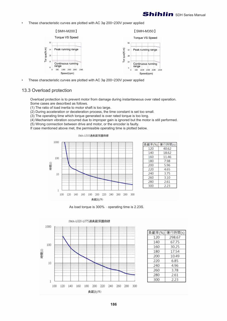
186
SDH Series Manual
• These characteristic curves are plotted with AC 3φ 200~230V power applied
【SMH-M200】 【SMH-M350】
• These characteristic curves are plotted with AC 3φ 200~230V power applied
13.3 Overload protection
Overload protection is to prevent motor from damage during instantaneous over rated operation.Some cases are described as follows.(1) The ratio of load inertia to motor shaft is too large.(2) During acceleration or deceleration process, the time constant is set too small.(3) The operating time which torque generated is over rated torque is too long.(4) Mechanism vibration occurred due to improper gain is ignored but the motor is still performed.(5) Wrong connection between drive and motor, or the encoder is faulty.If case mentioned above met, the permissible operating time is plotted below.
As load torque is 300%,operating time is 2.23S.

187
Chapter 13.
As load torque is 300%,operating time is 2.23S.
As load torque is 300%,operating time is 2.28S.
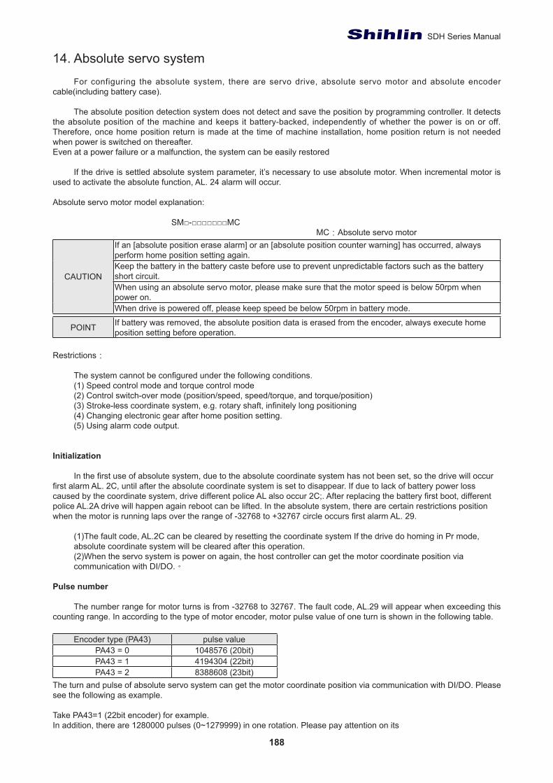
188
SDH Series Manual
14. Absolute servo system
For configuring the absolute system, there are servo drive, absolute servo motor and absolute encoder cable(including battery case).
The absolute position detection system does not detect and save the position by programming controller. It detects the absolute position of the machine and keeps it battery-backed, independently of whether the power is on or off. Therefore, once home position return is made at the time of machine installation, home position return is not needed when power is switched on thereafter.Even at a power failure or a malfunction, the system can be easily restored
If the drive is settled absolute system parameter, it’s necessary to use absolute motor. When incremental motor is used to activate the absolute function, AL. 24 alarm will occur.
Absolute servo motor model explanation:
SM□-□□□□□□□MCMC:Absolute servo motor
CAUTION
If an [absolute position erase alarm] or an [absolute position counter warning] has occurred, always perform home position setting again.Keep the battery in the battery caste before use to prevent unpredictable factors such as the battery short circuit.When using an absolute servo motor, please make sure that the motor speed is below 50rpm when power on.When drive is powered off, please keep speed be below 50rpm in battery mode.
POINT If battery was removed, the absolute position data is erased from the encoder, always execute home position setting before operation.
Restrictions:
The system cannot be configured under the following conditions. (1) Speed control mode and torque control mode(2) Control switch-over mode (position/speed, speed/torque, and torque/position)(3) Stroke-less coordinate system, e.g. rotary shaft, infinitely long positioning(4) Changing electronic gear after home position setting.(5) Using alarm code output.
Initialization
In the first use of absolute system, due to the absolute coordinate system has not been set, so the drive will occur first alarm AL. 2C, until after the absolute coordinate system is set to disappear. If due to lack of battery power loss caused by the coordinate system, drive different police AL also occur 2C;. After replacing the battery first boot, different police AL.2A drive will happen again reboot can be lifted. In the absolute system, there are certain restrictions position when the motor is running laps over the range of -32768 to +32767 circle occurs first alarm AL. 29.
(1)The fault code, AL.2C can be cleared by resetting the coordinate system If the drive do homing in Pr mode, absolute coordinate system will be cleared after this operation.(2)When the servo system is power on again, the host controller can get the motor coordinate position via communication with DI/DO.。
Pulse number
The number range for motor turns is from -32768 to 32767. The fault code, AL.29 will appear when exceeding this counting range. In according to the type of motor encoder, motor pulse value of one turn is shown in the following table.
Encoder type (PA43) pulse valuePA43 = 0 1048576 (20bit)PA43 = 1 4194304 (22bit)PA43 = 2 8388608 (23bit)
The turn and pulse of absolute servo system can get the motor coordinate position via communication with DI/DO. Please see the following as example.
Take PA43=1 (22bit encoder) for example.In addition, there are 1280000 pulses (0~1279999) in one rotation. Please pay attention on its
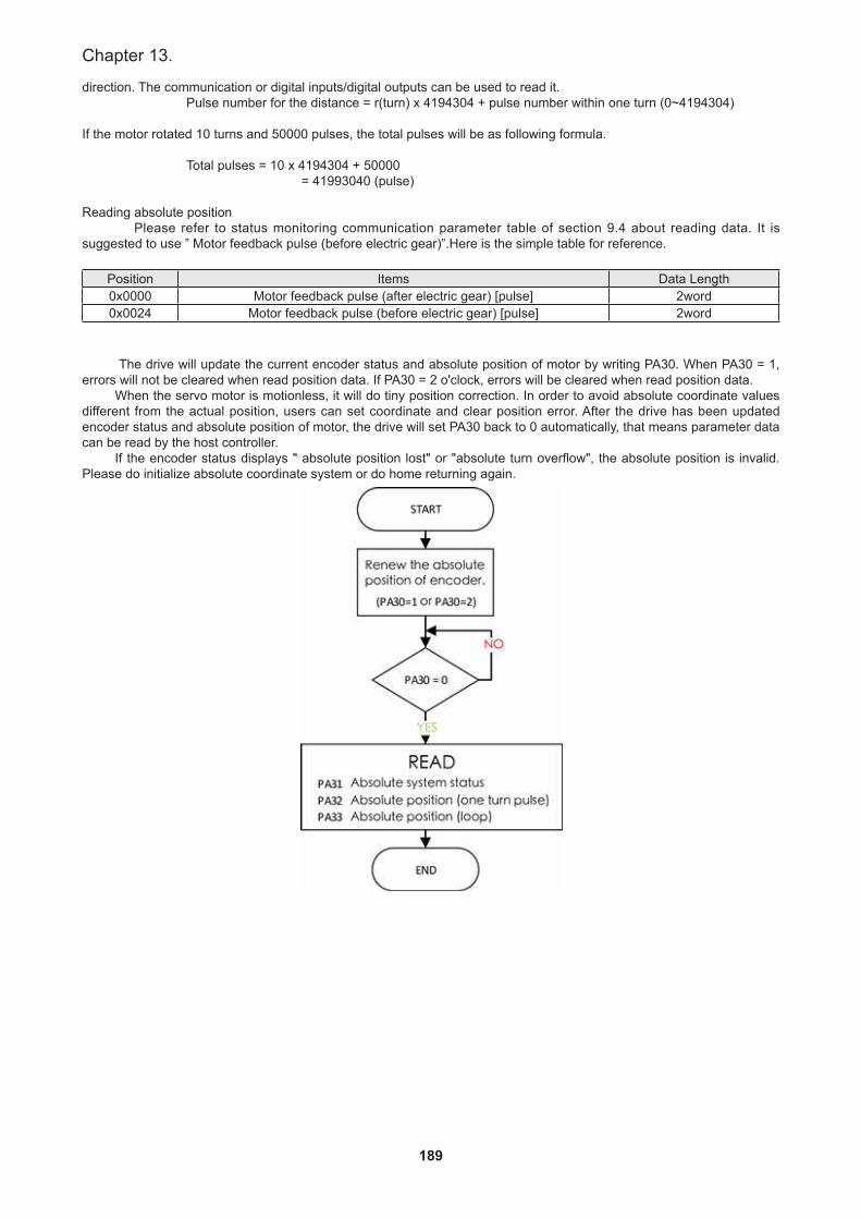
189
Chapter 13.
direction. The communication or digital inputs/digital outputs can be used to read it. Pulse number for the distance = r(turn) x 4194304 + pulse number within one turn (0~4194304)
If the motor rotated 10 turns and 50000 pulses, the total pulses will be as following formula.
Total pulses = 10 x 4194304 + 50000 = 41993040 (pulse)
Reading absolute position Please refer to status monitoring communication parameter table of section 9.4 about reading data. It is suggested to use ” Motor feedback pulse (before electric gear)”.Here is the simple table for reference.
Position Items Data Length0x0000 Motor feedback pulse (after electric gear) [pulse] 2word0x0024 Motor feedback pulse (before electric gear) [pulse] 2word
The drive will update the current encoder status and absolute position of motor by writing PA30. When PA30 = 1, errors will not be cleared when read position data. If PA30 = 2 o'clock, errors will be cleared when read position data.
When the servo motor is motionless, it will do tiny position correction. In order to avoid absolute coordinate values different from the actual position, users can set coordinate and clear position error. After the drive has been updated encoder status and absolute position of motor, the drive will set PA30 back to 0 automatically, that means parameter data can be read by the host controller.
If the encoder status displays " absolute position lost" or "absolute turn overflow", the absolute position is invalid. Please do initialize absolute coordinate system or do home returning again.
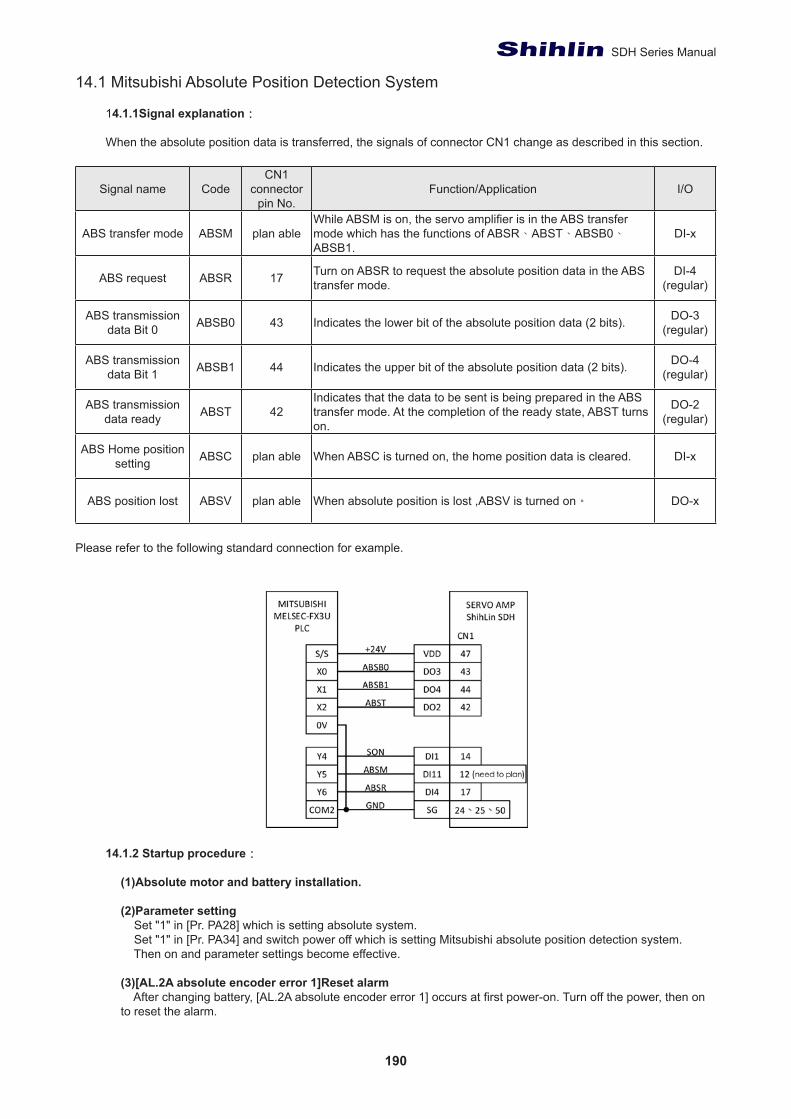
190
SDH Series Manual
14.1 Mitsubishi Absolute Position Detection System
14.1.1Signal explanation:
When the absolute position data is transferred, the signals of connector CN1 change as described in this section.
Signal name CodeCN1
connectorpin No.
Function/Application I/O
ABS transfer mode ABSM plan ableWhile ABSM is on, the servo amplifier is in the ABS transfer mode which has the functions of ABSR、ABST、ABSB0、ABSB1.
DI-x
ABS request ABSR 17 Turn on ABSR to request the absolute position data in the ABS transfer mode.
DI-4(regular)
ABS transmission data Bit 0 ABSB0 43 Indicates the lower bit of the absolute position data (2 bits). DO-3
(regular)
ABS transmission data Bit 1 ABSB1 44 Indicates the upper bit of the absolute position data (2 bits). DO-4
(regular)
ABS transmission data ready ABST 42
Indicates that the data to be sent is being prepared in the ABS transfer mode. At the completion of the ready state, ABST turns on.
DO-2(regular)
ABS Home position setting ABSC plan able When ABSC is turned on, the home position data is cleared. DI-x
ABS position lost ABSV plan able When absolute position is lost ,ABSV is turned on。 DO-x
Please refer to the following standard connection for example.
14.1.2 Startup procedure:
(1)Absolute motor and battery installation.
(2)Parameter setting Set "1" in [Pr. PA28] which is setting absolute system. Set "1" in [Pr. PA34] and switch power off which is setting Mitsubishi absolute position detection system. Then on and parameter settings become effective.
(3)[AL.2A absolute encoder error 1]Reset alarm After changing battery, [AL.2A absolute encoder error 1] occurs at first power-on. Turn off the power, then on to reset the alarm.
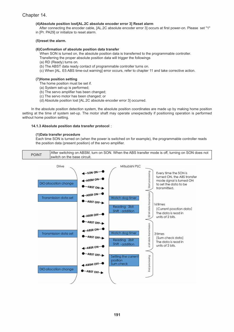
191
Chapter 14.
(4)Absolute position lost[AL.2C absolute encoder error 3] Reset alarm After connecting the encoder cable, [AL.2C absolute encoder error 3] occurs at first power-on. Please set "1" in [Pr. PA29] or initialize to reset alarm.
(5)reset the alarm.
(6)Confirmation of absolute position data transfer When SON is turned on, the absolute position data is transferred to the programmable controller. Transferring the proper absolute position data will trigger the followings (a) RD (Ready) turns on. (b) The ABST data ready contact of programmable controller turns on. (c) When [AL. E5 ABS time-out warning] error occurs, refer to chapter 11 and take corrective action.
(7)Home position setting The home position must be set if. (a) System set-up is performed; (b) The servo amplifier has been changed; (c) The servo motor has been changed; or (d) Absolute position lost [AL.2C absolute encoder error 3] occurred.
In the absolute position detection system, the absolute position coordinates are made up by making home position setting at the time of system set-up. The motor shaft may operate unexpectedly if positioning operation is performed without home position setting.
14.1.3 Absolute position data transfer protocol:
(1)Data transfer procedureEach time SON is turned on (when the power is switched on for example), the programmable controller reads the position data (present position) of the servo amplifier.
POINT After switching on ABSM, turn on SON. When the ABS transfer mode is off, turning on SON does not switch on the base circuit.
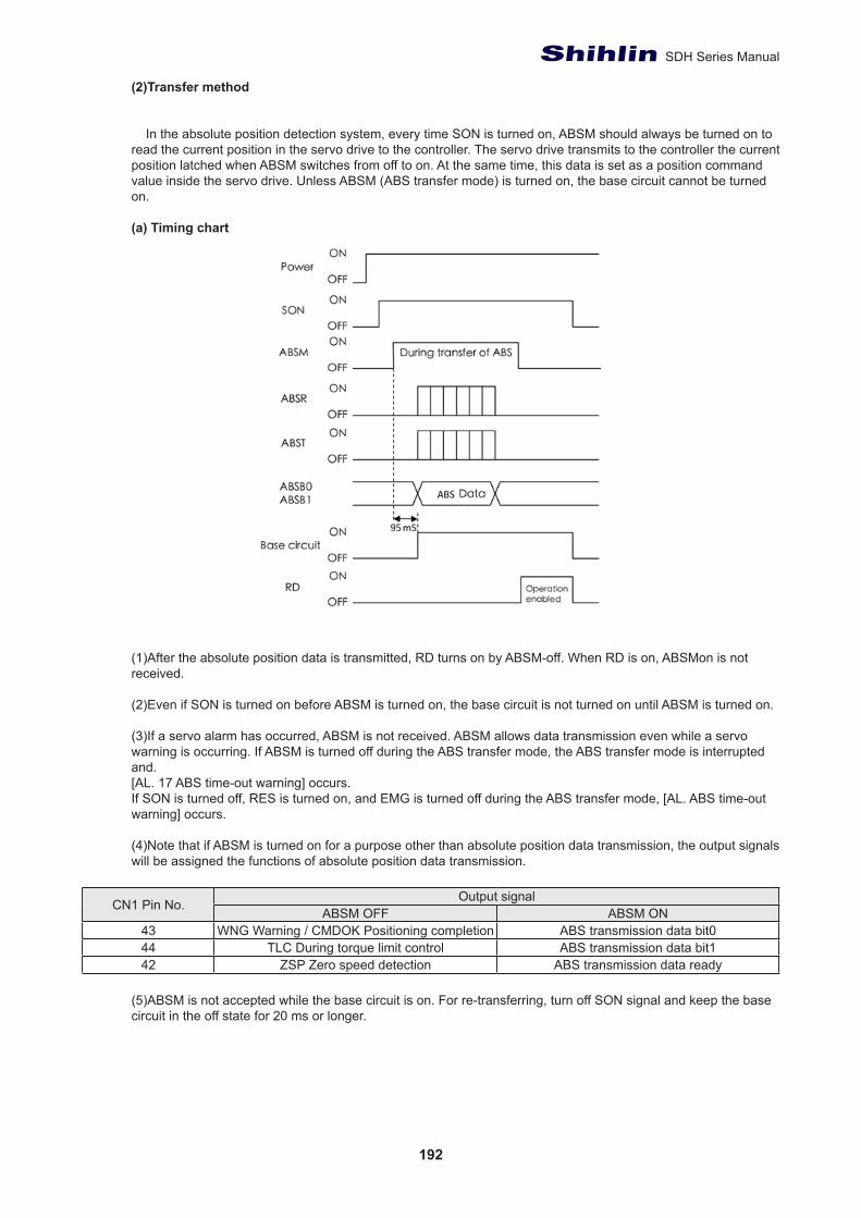
192
SDH Series Manual
(2)Transfer method
In the absolute position detection system, every time SON is turned on, ABSM should always be turned on to read the current position in the servo drive to the controller. The servo drive transmits to the controller the current position latched when ABSM switches from off to on. At the same time, this data is set as a position command value inside the servo drive. Unless ABSM (ABS transfer mode) is turned on, the base circuit cannot be turned on.
(a) Timing chart
(1)After the absolute position data is transmitted, RD turns on by ABSM-off. When RD is on, ABSMon is not received.
(2)Even if SON is turned on before ABSM is turned on, the base circuit is not turned on until ABSM is turned on.
(3)If a servo alarm has occurred, ABSM is not received. ABSM allows data transmission even while a servo warning is occurring. If ABSM is turned off during the ABS transfer mode, the ABS transfer mode is interrupted and.[AL. 17 ABS time-out warning] occurs.If SON is turned off, RES is turned on, and EMG is turned off during the ABS transfer mode, [AL. ABS time-out warning] occurs.
(4)Note that if ABSM is turned on for a purpose other than absolute position data transmission, the output signals will be assigned the functions of absolute position data transmission.
CN1 Pin No. Output signalABSM OFF ABSM ON
43 WNG Warning / CMDOK Positioning completion ABS transmission data bit044 TLC During torque limit control ABS transmission data bit142 ZSP Zero speed detection ABS transmission data ready
(5)ABSM is not accepted while the base circuit is on. For re-transferring, turn off SON signal and keep the base circuit in the off state for 20 ms or longer.
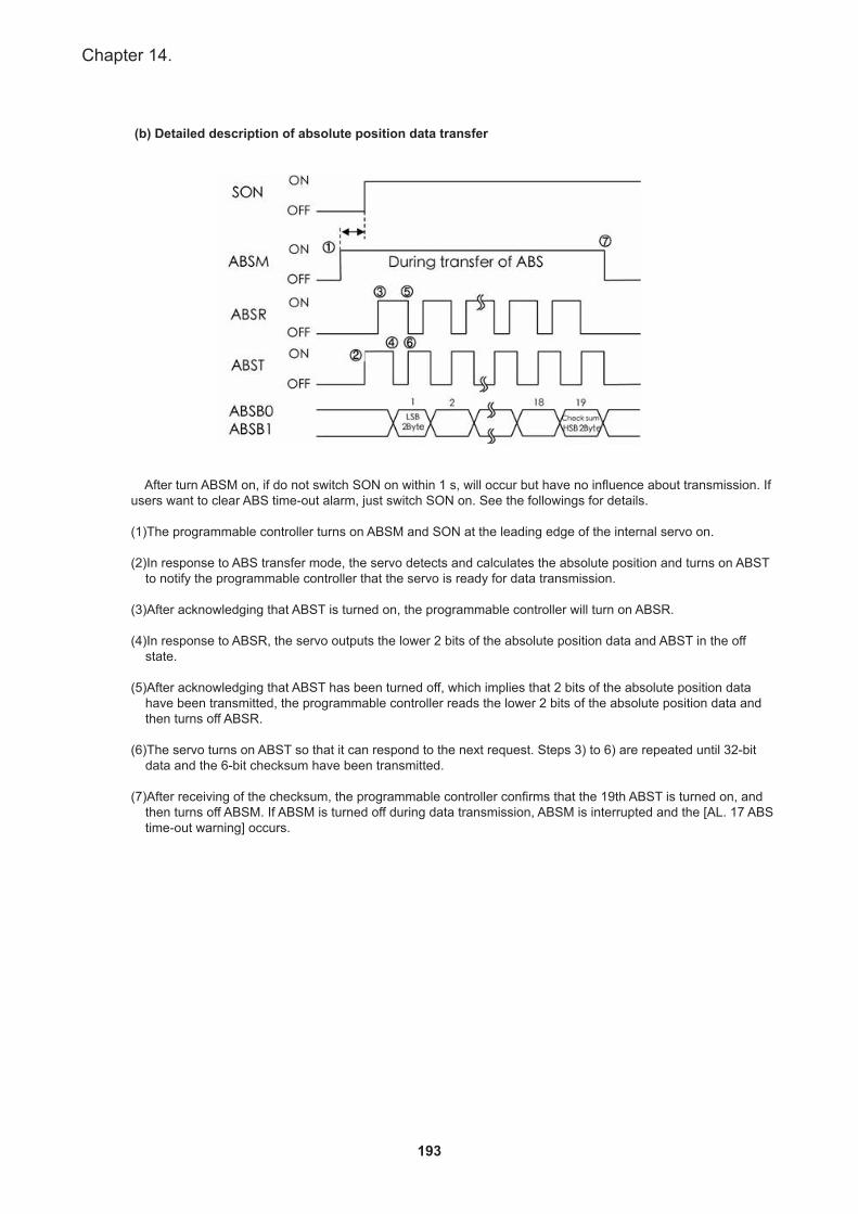
193
Chapter 14.
(b) Detailed description of absolute position data transfer
After turn ABSM on, if do not switch SON on within 1 s, will occur but have no influence about transmission. If users want to clear ABS time-out alarm, just switch SON on. See the followings for details.
(1)The programmable controller turns on ABSM and SON at the leading edge of the internal servo on.
(2)In response to ABS transfer mode, the servo detects and calculates the absolute position and turns on ABST to notify the programmable controller that the servo is ready for data transmission.
(3)After acknowledging that ABST is turned on, the programmable controller will turn on ABSR.
(4)In response to ABSR, the servo outputs the lower 2 bits of the absolute position data and ABST in the off state.
(5)After acknowledging that ABST has been turned off, which implies that 2 bits of the absolute position data have been transmitted, the programmable controller reads the lower 2 bits of the absolute position data and then turns off ABSR.
(6)The servo turns on ABST so that it can respond to the next request. Steps 3) to 6) are repeated until 32-bit data and the 6-bit checksum have been transmitted.
(7)After receiving of the checksum, the programmable controller confirms that the 19th ABST is turned on, and then turns off ABSM. If ABSM is turned off during data transmission, ABSM is interrupted and the [AL. 17 ABS time-out warning] occurs.
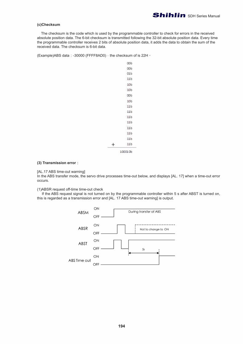
194
SDH Series Manual
(c)Checksum
The checksum is the code which is used by the programmable controller to check for errors in the received absolute position data. The 6-bit checksum is transmitted following the 32-bit absolute position data. Every time the programmable controller receives 2 bits of absolute position data, it adds the data to obtain the sum of the received data. The checksum is 6-bit data.
(Example)ABS data:-30000 (FFFF8AD0),the checksum of is 22H。
(3) Transmission error:
[AL.17 ABS time-out warning]In the ABS transfer mode, the servo drive processes time-out below, and displays [AL. 17] when a time-out error occurs.
(1)ABSR request off-time time-out check If the ABS request signal is not turned on by the programmable controller within 5 s after ABST is turned on, this is regarded as a transmission error and [AL. 17 ABS time-out warning] is output.
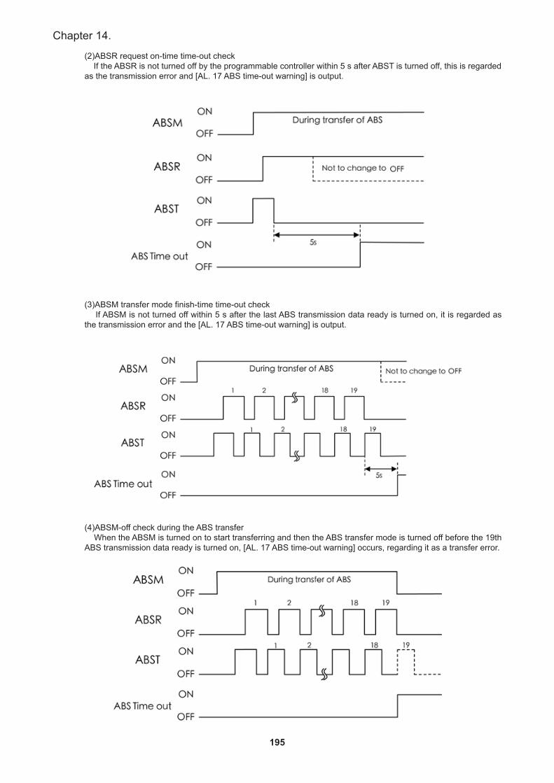
195
Chapter 14.
(2)ABSR request on-time time-out check If the ABSR is not turned off by the programmable controller within 5 s after ABST is turned off, this is regarded as the transmission error and [AL. 17 ABS time-out warning] is output.
(3)ABSM transfer mode finish-time time-out check If ABSM is not turned off within 5 s after the last ABS transmission data ready is turned on, it is regarded as the transmission error and the [AL. 17 ABS time-out warning] is output.
(4)ABSM-off check during the ABS transfer When the ABSM is turned on to start transferring and then the ABS transfer mode is turned off before the 19th ABS transmission data ready is turned on, [AL. 17 ABS time-out warning] occurs, regarding it as a transfer error.
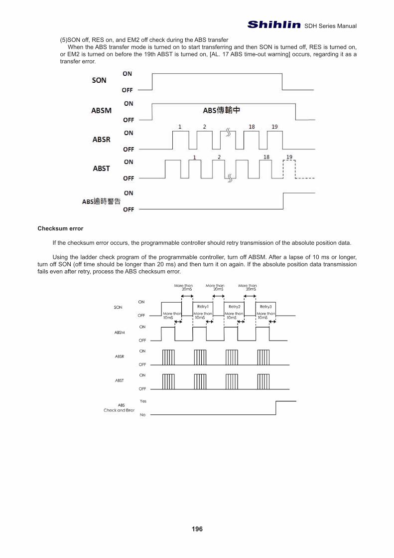
196
SDH Series Manual
(5)SON off, RES on, and EM2 off check during the ABS transfer When the ABS transfer mode is turned on to start transferring and then SON is turned off, RES is turned on, or EM2 is turned on before the 19th ABST is turned on, [AL. 17 ABS time-out warning] occurs, regarding it as a transfer error.
Checksum error
If the checksum error occurs, the programmable controller should retry transmission of the absolute position data.
Using the ladder check program of the programmable controller, turn off ABSM. After a lapse of 10 ms or longer, turn off SON (off time should be longer than 20 ms) and then turn it on again. If the absolute position data transmission fails even after retry, process the ABS checksum error.
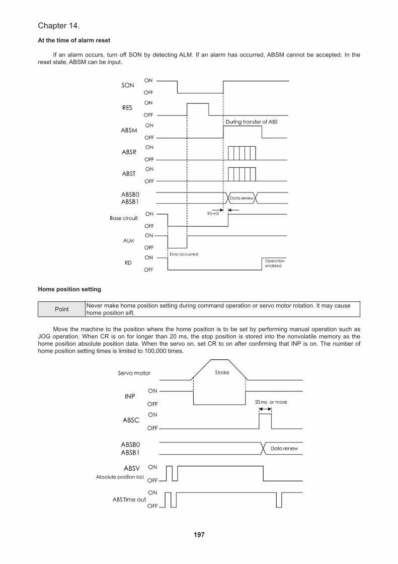
197
Chapter 14.
At the time of alarm reset
If an alarm occurs, turn off SON by detecting ALM. If an alarm has occurred, ABSM cannot be accepted. In the reset state, ABSM can be input.
Home position setting
Point Never make home position setting during command operation or servo motor rotation. It may cause home position sift.
Move the machine to the position where the home position is to be set by performing manual operation such as
JOG operation. When CR is on for longer than 20 ms, the stop position is stored into the nonvolatile memory as the home position absolute position data. When the servo on, set CR to on after confirming that INP is on. The number of home position setting times is limited to 100,000 times.
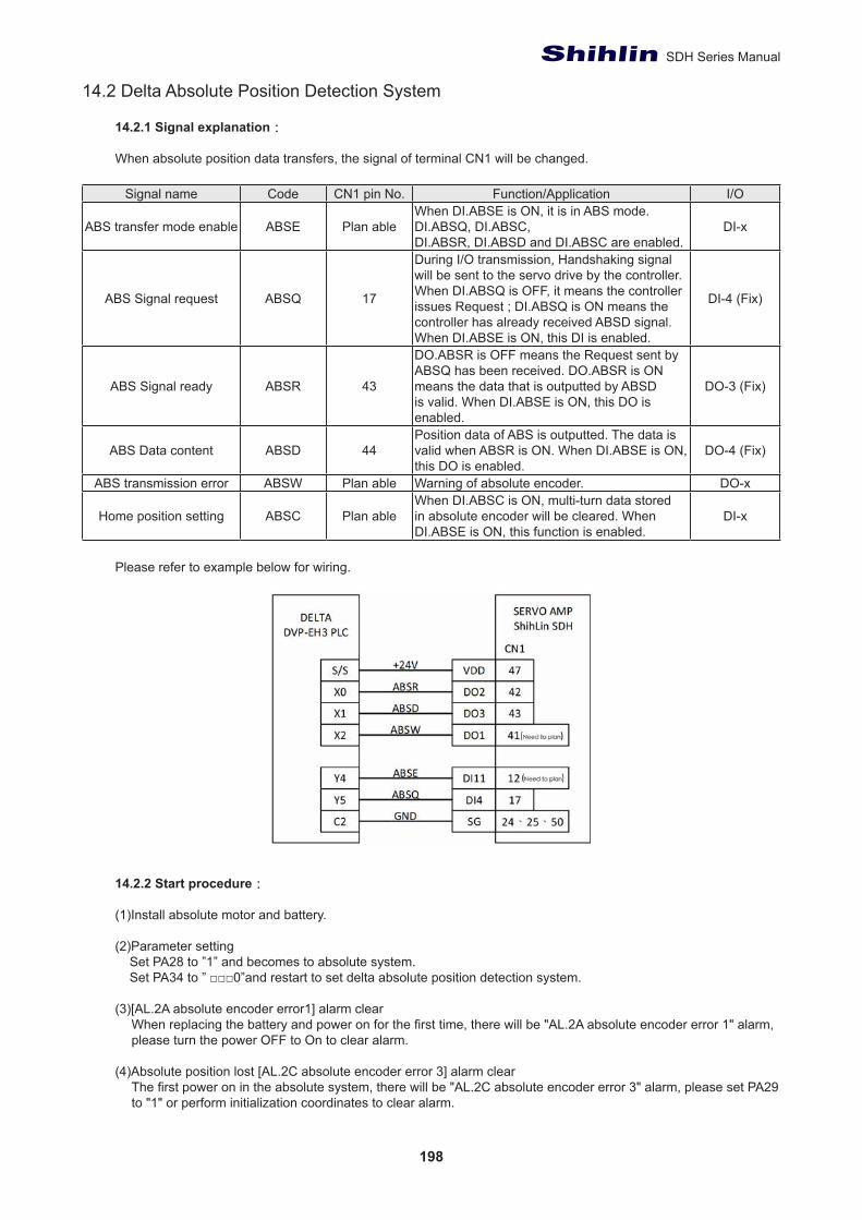
198
SDH Series Manual
14.2 Delta Absolute Position Detection System
14.2.1 Signal explanation:
When absolute position data transfers, the signal of terminal CN1 will be changed.
Signal name Code CN1 pin No. Function/Application I/O
ABS transfer mode enable ABSE Plan ableWhen DI.ABSE is ON, it is in ABS mode. DI.ABSQ, DI.ABSC,DI.ABSR, DI.ABSD and DI.ABSC are enabled.
DI-x
ABS Signal request ABSQ 17
During I/O transmission, Handshaking signal will be sent to the servo drive by the controller. When DI.ABSQ is OFF, it means the controller issues Request ; DI.ABSQ is ON means the controller has already received ABSD signal. When DI.ABSE is ON, this DI is enabled.
DI-4 (Fix)
ABS Signal ready ABSR 43
DO.ABSR is OFF means the Request sent by ABSQ has been received. DO.ABSR is ON means the data that is outputted by ABSD is valid. When DI.ABSE is ON, this DO is enabled.
DO-3 (Fix)
ABS Data content ABSD 44Position data of ABS is outputted. The data is valid when ABSR is ON. When DI.ABSE is ON, this DO is enabled.
DO-4 (Fix)
ABS transmission error ABSW Plan able Warning of absolute encoder. DO-x
Home position setting ABSC Plan ableWhen DI.ABSC is ON, multi-turn data stored in absolute encoder will be cleared. When DI.ABSE is ON, this function is enabled.
DI-x
Please refer to example below for wiring.
14.2.2 Start procedure:
(1)Install absolute motor and battery.
(2)Parameter setting Set PA28 to ”1” and becomes to absolute system. Set PA34 to ” □□□0”and restart to set delta absolute position detection system.
(3)[AL.2A absolute encoder error1] alarm clearWhen replacing the battery and power on for the first time, there will be "AL.2A absolute encoder error 1" alarm, please turn the power OFF to On to clear alarm.
(4)Absolute position lost [AL.2C absolute encoder error 3] alarm clearThe first power on in the absolute system, there will be "AL.2C absolute encoder error 3" alarm, please set PA29 to "1" or perform initialization coordinates to clear alarm.

199
Chapter 14.
(5)Home returningPlease perform home setting as following conditions. (a) set up absolute system. (b) Replace the servo drive. (c) Replace the servo motor.(d) When absolute position lost occurs [AL.2C absolute encoder error 3]alarm
When setting the absolute position system, users can establish absolute coordinate position by home setting. With no home setting and operate the motor, an unexpected action will occur.
14.2.3 Use Digital Inputs/Outputs to Initialize an Absolute System:
Initialize an absolute system by DI/DO method or writing PA29 parameter. Please do homing to initialize absolute coordinates in Pr mode. Move the motor to home place, enable digital input, ABSE, then enable digital input, ABSC from OFF to ON, and the system will start to initialization. The pulse number will be set to zero. Please refer to Figure below for the signal controlling chart.
Ts(ms) Tq(ms)
Min PD15 + 2Max PD15 + 10
The descriptions for the timing:
1.When the host controller switches ABSE from OFF to ON, a period of time Ts have to be waited for the next step to process.
2.After waiting time Ts, the host controller now can enable the ABSC from OFF to ON and hold the signal for TQ to reset the coordinate system where pulse number will be zero.
14.2.4 Use Parameters to Initialize an Absolute System
Initialize an absolute system by panel operation or writing PA29 parameter. When 1 was written into PA29, absolute coordinates will initialize immediately. Please do homing to initialize absolute coordinates in Pr mode.
Bit79 ~ Bit64 Bit63 ~ Bit32 Bit31 ~ Bit16 Bit15 ~ Bit0
Check Sum Encoder pulse within one turn0 ~ 4194304 (22bit Encoder)
Encoder turn-32768 ~ +32767 PA30 Encoder status
Explanation:
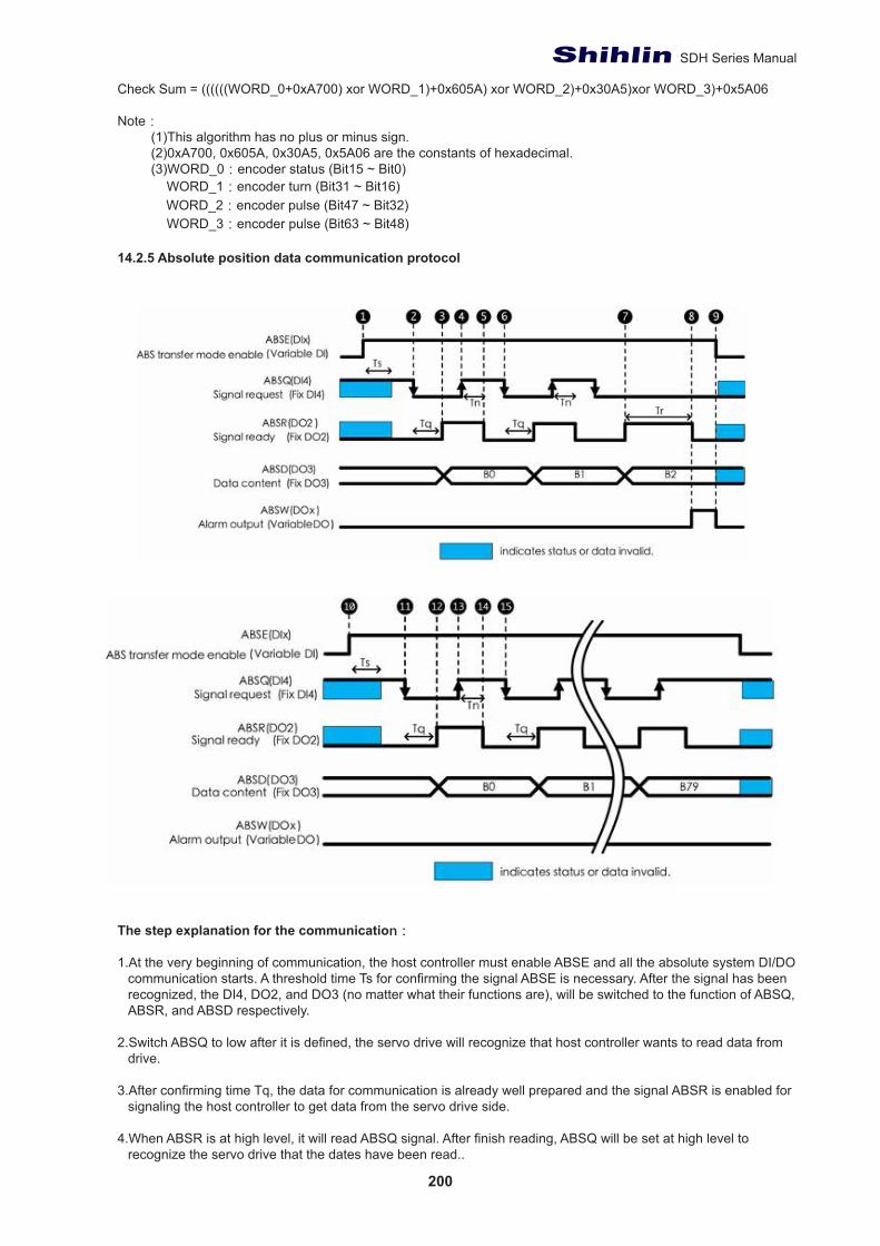
200
SDH Series Manual
Check Sum = ((((((WORD_0+0xA700) xor WORD_1)+0x605A) xor WORD_2)+0x30A5)xor WORD_3)+0x5A06
Note:(1)This algorithm has no plus or minus sign. (2)0xA700, 0x605A, 0x30A5, 0x5A06 are the constants of hexadecimal.(3)WORD_0:encoder status (Bit15 ~ Bit0) WORD_1:encoder turn (Bit31 ~ Bit16) WORD_2:encoder pulse (Bit47 ~ Bit32) WORD_3:encoder pulse (Bit63 ~ Bit48)
14.2.5 Absolute position data communication protocol
The step explanation for the communication:
1.At the very beginning of communication, the host controller must enable ABSE and all the absolute system DI/DO communication starts. A threshold time Ts for confirming the signal ABSE is necessary. After the signal has beenrecognized, the DI4, DO2, and DO3 (no matter what their functions are), will be switched to the function of ABSQ, ABSR, and ABSD respectively.
2.Switch ABSQ to low after it is defined, the servo drive will recognize that host controller wants to read data from drive.
3.After confirming time Tq, the data for communication is already well prepared and the signal ABSR is enabled for signaling the host controller to get data from the servo drive side.
4.When ABSR is at high level, it will read ABSQ signal. After finish reading, ABSQ will be set at high level to recognize the servo drive that the dates have been read..
201
Chapter 14.
5.After confirming time TN, the servo drive will maintain ABSR to low for signaling the host controller to be ready for accessing next bit.
6.The host controller detects that ABSR is in low level will request the drive for accessing next bit.
7.The drive finished preparing data then enable ABSR.
8.After the data is ready and has been held for time Try, the servo drive still does not see the signal ABSQ controlled by the host controller, and then the servo drive will have a communication error flag ABSW raise to terminate the communication procedure.
9.The host controller detects that ABSR communication is wrong will set ABSE in low level and restart to communicate.
10.Enable ABSE again and restart communication.
11.The host controller set ABSQ in low level and request to read.
12.After confirming time Tq, the drive will inform the host controller that data could be read.
13.After the host controller detects that ABSR is high, the data is fetched. The ABSQ will be set to signal high to inform the drive after dada read.
14.After confirming time Tn for ABSQ kept high, the servo drive will maintain ABSR to low for signaling the host controller to be ready for accessing next bit.
15.By repeating steps 11 t o 14, to finish bit 0 to bit 79 (80 bits data) communication.
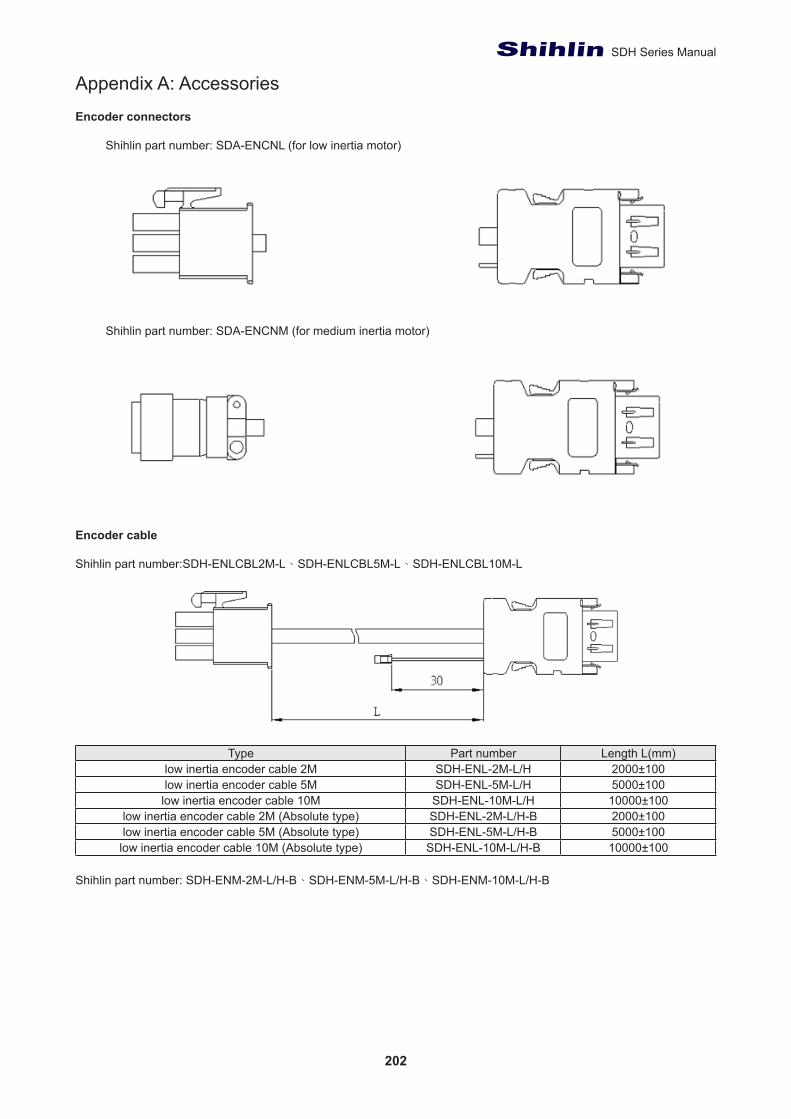
202
SDH Series Manual
Appendix A: Accessories
Encoder connectors
Shihlin part number: SDA-ENCNL (for low inertia motor)
Shihlin part number: SDA-ENCNM (for medium inertia motor)
Encoder cable
Shihlin part number:SDH-ENLCBL2M-L、SDH-ENLCBL5M-L、SDH-ENLCBL10M-L
Type Part number Length L(mm)low inertia encoder cable 2M SDH-ENL-2M-L/H 2000±100low inertia encoder cable 5M SDH-ENL-5M-L/H 5000±100
low inertia encoder cable 10M SDH-ENL-10M-L/H 10000±100low inertia encoder cable 2M (Absolute type) SDH-ENL-2M-L/H-B 2000±100low inertia encoder cable 5M (Absolute type) SDH-ENL-5M-L/H-B 5000±100
low inertia encoder cable 10M (Absolute type) SDH-ENL-10M-L/H-B 10000±100
Shihlin part number: SDH-ENM-2M-L/H-B、SDH-ENM-5M-L/H-B、SDH-ENM-10M-L/H-B
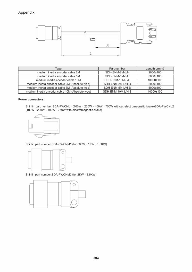
203
Appendix.
Type Part number Length L(mm)
medium inertia encoder cable 2M SDH-ENM-2M-L/H 2000±100medium inertia encoder cable 5M SDH-ENM-5M-L/H 5000±100medium inertia encoder cable 10M SDH-ENM-10M-L/H 10000±100
medium inertia encoder cable 2M (Absolute type) SDH-ENM-2M-L/H-B 2000±100medium inertia encoder cable 5M (Absolute type) SDH-ENM-5M-L/H-B 5000±100
medium inertia encoder cable 10M (Absolute type) SDH-ENM-10M-L/H-B 10000±100
Power connectors
Shihlin part number:SDA-PWCNL1 (100W、200W、400W、750W without electromagnetic brake)SDA-PWCNL2 (100W、200W、400W、750W with electromagnetic brake)
Shihlin part number:SDA-PWCNM1 (for 500W、1KW、1.5KW)
Shihlin part number:SDA-PWCNM2 (for 2KW、3.5KW)
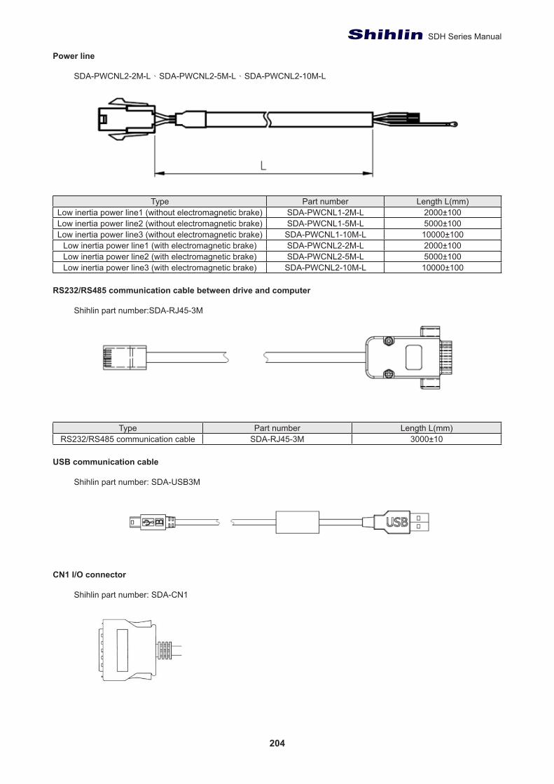
204
SDH Series Manual
Power line
SDA-PWCNL2-2M-L、SDA-PWCNL2-5M-L、SDA-PWCNL2-10M-L
Type Part number Length L(mm)Low inertia power line1 (without electromagnetic brake) SDA-PWCNL1-2M-L 2000±100Low inertia power line2 (without electromagnetic brake) SDA-PWCNL1-5M-L 5000±100Low inertia power line3 (without electromagnetic brake) SDA-PWCNL1-10M-L 10000±100
Low inertia power line1 (with electromagnetic brake) SDA-PWCNL2-2M-L 2000±100Low inertia power line2 (with electromagnetic brake) SDA-PWCNL2-5M-L 5000±100Low inertia power line3 (with electromagnetic brake) SDA-PWCNL2-10M-L 10000±100
RS232/RS485 communication cable between drive and computer
Shihlin part number:SDA-RJ45-3M
Type Part number Length L(mm)RS232/RS485 communication cable SDA-RJ45-3M 3000±10
USB communication cable
Shihlin part number: SDA-USB3M
CN1 I/O connector
Shihlin part number: SDA-CN1
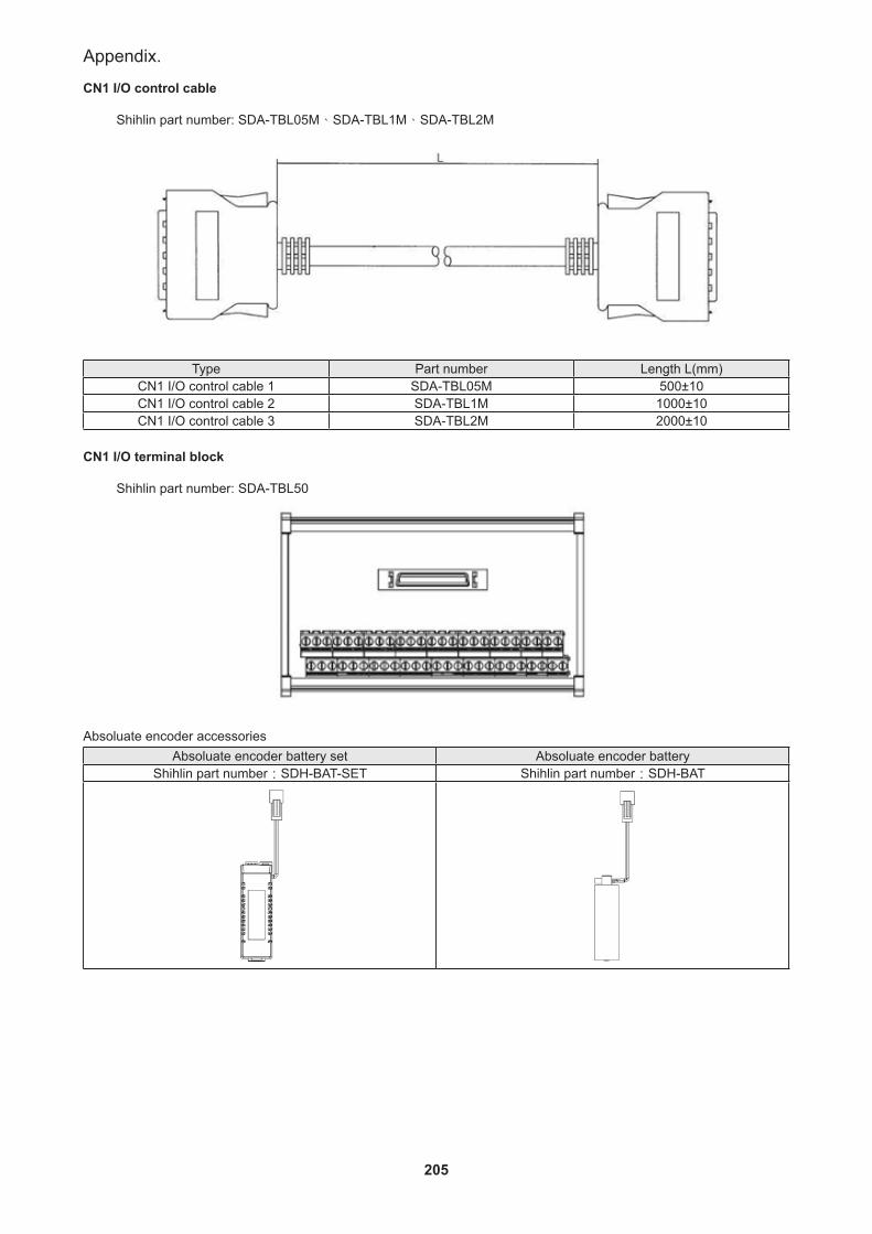
205
Appendix.
CN1 I/O control cable Shihlin part number: SDA-TBL05M、SDA-TBL1M、SDA-TBL2M
Type Part number Length L(mm)CN1 I/O control cable 1 SDA-TBL05M 500±10CN1 I/O control cable 2 SDA-TBL1M 1000±10CN1 I/O control cable 3 SDA-TBL2M 2000±10
CN1 I/O terminal block
Shihlin part number: SDA-TBL50
Absoluate encoder accessoriesAbsoluate encoder battery set Absoluate encoder battery
Shihlin part number:SDH-BAT-SET Shihlin part number:SDH-BAT

206
SDH Series Manual
Brake resistor:
Drive typeBuilt-in resistor External resistor (suggestion) Brake resistor part
No.Resistance (Ω) Capacity (W) Permissible Min resistance(Ω) Capacity (W)
SDH-010A2 100 20 100 500 ABR-500W100SDH-020A2 100 20 100 500 ABR-500W100SDH-040A2 100 20 100 500 ABR-500W100SDH-050A2 100 20 100 500 ABR-500W100SDH-075A2 40 40 40 1000 ABR-1000W40SDH-100A2 40 40 40 1000 ABR-1000W40SDH-150A2 13 100 13 1000 ABR-1000W13SDH-200A2 13 100 13 1000 ABR-1000W13SDH-350A2 13 100 13 1000 ABR-1000W13
★ To confirm that P and D terminal are in open-circuit status and that P and C terminal are connected with the external brake resistor.
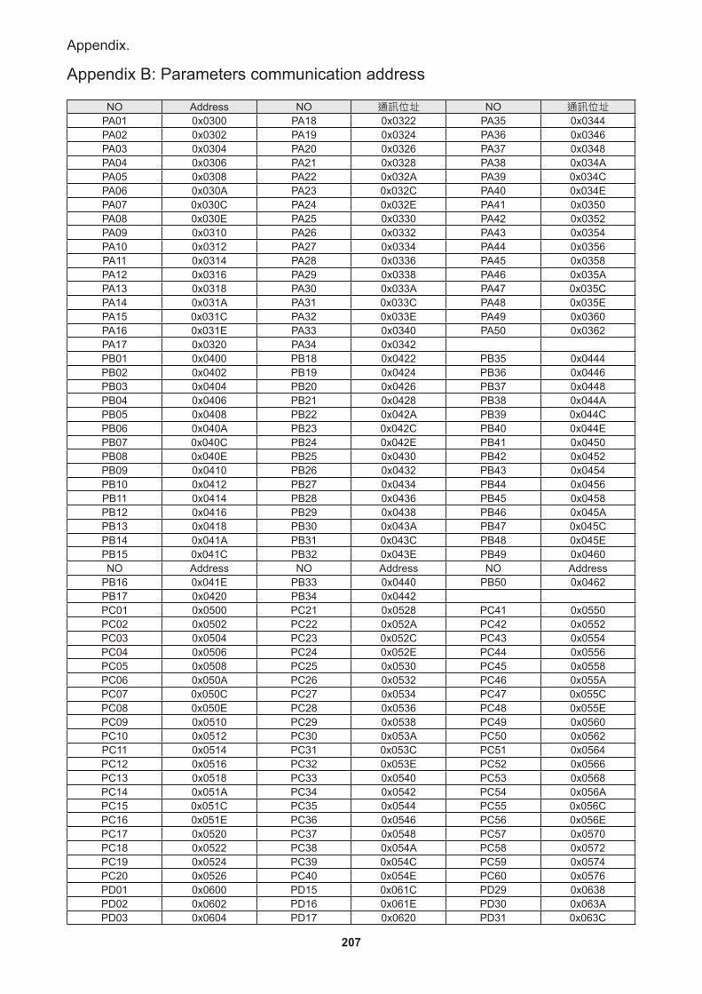
207
Appendix.
Appendix B: Parameters communication address
NO Address NO 通訊位址 NO 通訊位址PA01 0x0300 PA18 0x0322 PA35 0x0344PA02 0x0302 PA19 0x0324 PA36 0x0346PA03 0x0304 PA20 0x0326 PA37 0x0348PA04 0x0306 PA21 0x0328 PA38 0x034APA05 0x0308 PA22 0x032A PA39 0x034CPA06 0x030A PA23 0x032C PA40 0x034EPA07 0x030C PA24 0x032E PA41 0x0350PA08 0x030E PA25 0x0330 PA42 0x0352PA09 0x0310 PA26 0x0332 PA43 0x0354PA10 0x0312 PA27 0x0334 PA44 0x0356PA11 0x0314 PA28 0x0336 PA45 0x0358PA12 0x0316 PA29 0x0338 PA46 0x035APA13 0x0318 PA30 0x033A PA47 0x035CPA14 0x031A PA31 0x033C PA48 0x035EPA15 0x031C PA32 0x033E PA49 0x0360PA16 0x031E PA33 0x0340 PA50 0x0362PA17 0x0320 PA34 0x0342PB01 0x0400 PB18 0x0422 PB35 0x0444PB02 0x0402 PB19 0x0424 PB36 0x0446PB03 0x0404 PB20 0x0426 PB37 0x0448PB04 0x0406 PB21 0x0428 PB38 0x044APB05 0x0408 PB22 0x042A PB39 0x044CPB06 0x040A PB23 0x042C PB40 0x044EPB07 0x040C PB24 0x042E PB41 0x0450PB08 0x040E PB25 0x0430 PB42 0x0452PB09 0x0410 PB26 0x0432 PB43 0x0454PB10 0x0412 PB27 0x0434 PB44 0x0456PB11 0x0414 PB28 0x0436 PB45 0x0458PB12 0x0416 PB29 0x0438 PB46 0x045APB13 0x0418 PB30 0x043A PB47 0x045CPB14 0x041A PB31 0x043C PB48 0x045EPB15 0x041C PB32 0x043E PB49 0x0460NO Address NO Address NO Address
PB16 0x041E PB33 0x0440 PB50 0x0462PB17 0x0420 PB34 0x0442PC01 0x0500 PC21 0x0528 PC41 0x0550PC02 0x0502 PC22 0x052A PC42 0x0552PC03 0x0504 PC23 0x052C PC43 0x0554PC04 0x0506 PC24 0x052E PC44 0x0556PC05 0x0508 PC25 0x0530 PC45 0x0558PC06 0x050A PC26 0x0532 PC46 0x055APC07 0x050C PC27 0x0534 PC47 0x055CPC08 0x050E PC28 0x0536 PC48 0x055EPC09 0x0510 PC29 0x0538 PC49 0x0560PC10 0x0512 PC30 0x053A PC50 0x0562PC11 0x0514 PC31 0x053C PC51 0x0564PC12 0x0516 PC32 0x053E PC52 0x0566PC13 0x0518 PC33 0x0540 PC53 0x0568PC14 0x051A PC34 0x0542 PC54 0x056APC15 0x051C PC35 0x0544 PC55 0x056CPC16 0x051E PC36 0x0546 PC56 0x056EPC17 0x0520 PC37 0x0548 PC57 0x0570PC18 0x0522 PC38 0x054A PC58 0x0572PC19 0x0524 PC39 0x054C PC59 0x0574PC20 0x0526 PC40 0x054E PC60 0x0576PD01 0x0600 PD15 0x061C PD29 0x0638PD02 0x0602 PD16 0x061E PD30 0x063APD03 0x0604 PD17 0x0620 PD31 0x063C
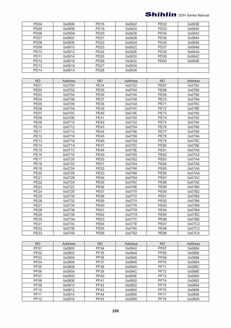
208
SDH Series Manual
PD04 0x0606 PD18 0x0622 PD32 0x063EPD05 0x0608 PD19 0x0624 PD33 0x0640PD06 0x060A PD20 0x0626 PD34 0x0642PD07 0x060C PD21 0x0628 PD35 0x0644PD08 0x060E PD22 0x062A PD36 0x0646PD09 0x0610 PD23 0x062C PD37 0x0648PD10 0x0612 PD24 0x062E PD38 0x064APD11 0x0614 PD25 0x0630 PD39 0x064CPD12 0x0616 PD26 0x0632 PD40 0x064EPD13 0x0618 PD27 0x0634PD14 0x061A PD28 0x0636
NO Address NO Address NO Address
PE01 0x0700 PE34 0x0742 PE67 0x0784PE02 0x0702 PE35 0x0744 PE68 0x0786PE03 0x0704 PE36 0x0746 PE69 0x0788PE04 0x0706 PE37 0x0748 PE70 0x078APE05 0x0708 PE38 0x074A PE71 0x078CPE06 0x070A PE39 0x074C PE72 0x078EPE07 0x070C PE40 0x074E PE73 0x0790PE08 0x070E PE41 0x0750 PE74 0x0792PE09 0x0710 PE42 0x0752 PE75 0x0794PE10 0x0712 PE43 0x0754 PE76 0x0796PE11 0x0714 PE44 0x0756 PE77 0x0798PE12 0x0716 PE45 0x0758 PE78 0x079APE13 0x0718 PE46 0x075A PE79 0x079CPE14 0x071A PE47 0x075C PE80 0x079EPE15 0x071C PE48 0x075E PE81 0x07A0PE16 0x071E PE49 0x0760 PE82 0x07A2PE17 0x0720 PE50 0x0762 PE83 0x07A4PE18 0x0722 PE51 0x0764 PE84 0x07A6PE19 0x0724 PE52 0x0766 PE85 0x07A8PE20 0x0726 PE53 0x0768 PE86 0x07AAPE21 0x0728 PE54 0x076A PE87 0x07ACPE22 0x072A PE55 0x076C PE88 0x07AEPE23 0x072C PE56 0x076E PE89 0x07B0PE24 0x072E PE57 0x0770 PE90 0x07B2PE25 0x0730 PE58 0x0772 PE91 0x07B4PE26 0x0732 PE59 0x0774 PE92 0x07B6PE27 0x0734 PE60 0x0776 PE93 0x07B8PE28 0x0736 PE61 0x0778 PE94 0x07BAPE29 0x0738 PE62 0x077A PE95 0x07BCPE30 0x073A PE63 0x077C PE96 0x07BEPE31 0x073C PE64 0x077E PE97 0x07C0PE32 0x073E PE65 0x0780 PE98 0x07C2PE33 0x0740 PE66 0x0782 PE99 0x07C4
NO Address NO Address NO AddressPF01 0x0800 PF34 0x0842 PF67 0x0884PF02 0x0802 PF35 0x0844 PF68 0x0886PF03 0x0804 PF36 0x0846 PF69 0x0888PF04 0x0806 PF37 0x0848 PF70 0x088APF05 0x0808 PF38 0x084A PF71 0x088CPF06 0x080A PF39 0x084C PF72 0x088EPF07 0x080C PF40 0x084E PF73 0x0890PF08 0x080E PF41 0x0850 PF74 0x0892PF09 0x0810 PF42 0x0852 PF75 0x0894PF10 0x0812 PF43 0x0854 PF76 0x0896PF11 0x0814 PF44 0x0856 PF77 0x0898PF12 0x0816 PF45 0x0858 PF78 0x089A
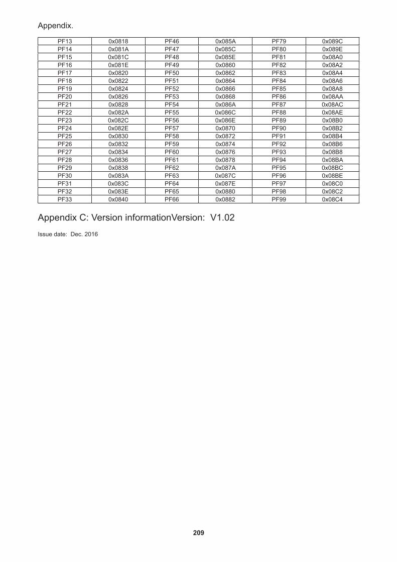
209
Appendix.
PF13 0x0818 PF46 0x085A PF79 0x089CPF14 0x081A PF47 0x085C PF80 0x089EPF15 0x081C PF48 0x085E PF81 0x08A0PF16 0x081E PF49 0x0860 PF82 0x08A2PF17 0x0820 PF50 0x0862 PF83 0x08A4PF18 0x0822 PF51 0x0864 PF84 0x08A6PF19 0x0824 PF52 0x0866 PF85 0x08A8PF20 0x0826 PF53 0x0868 PF86 0x08AAPF21 0x0828 PF54 0x086A PF87 0x08ACPF22 0x082A PF55 0x086C PF88 0x08AEPF23 0x082C PF56 0x086E PF89 0x08B0PF24 0x082E PF57 0x0870 PF90 0x08B2PF25 0x0830 PF58 0x0872 PF91 0x08B4PF26 0x0832 PF59 0x0874 PF92 0x08B6PF27 0x0834 PF60 0x0876 PF93 0x08B8PF28 0x0836 PF61 0x0878 PF94 0x08BAPF29 0x0838 PF62 0x087A PF95 0x08BCPF30 0x083A PF63 0x087C PF96 0x08BEPF31 0x083C PF64 0x087E PF97 0x08C0PF32 0x083E PF65 0x0880 PF98 0x08C2PF33 0x0840 PF66 0x0882 PF99 0x08C4
Appendix C: Version informationVersion: V1.02
Issue date: Dec. 2016


2016