SD 1.5.1 Hull Form
48
1 Hull Form Manuel Ventura Ship Design I MSc in Marine Engineering and Naval Architecture M.Ventura Hull Form 2 Summary 1. Introduction 2. Types of hulls 3. Development of the form • Systematic series • Geometric modeling 4. Alteration of the form • Alteration of the Prismatic Coefficient • Alteration of the LCB
-
Upload
adiwirawan3837 -
Category
Documents
-
view
256 -
download
9
Transcript of SD 1.5.1 Hull Form
1
Hull Form
Manuel Ventura
Ship Design I
MSc in Marine Engineering and Naval Architecture
M.Ventura Hull Form 2
Summary
1. Introduction2. Types of hulls3. Development of the form
• Systematic series• Geometric modeling
4. Alteration of the form• Alteration of the Prismatic Coefficient• Alteration of the LCB
2
M.Ventura Hull Form 3
Introduction
• Capacity– Volume– Spatial distribution of the volume– Displacement
• Stability– Intact
• Hydrodynamics– Service speed (loaded / ballast)– Seakeeping– Maneuverability
• Functionality• Aesthetical
– Pleasant form
The hull form is a compromise resulting from the need to satisfy a set of different types of requirements:
M.Ventura Hull Form 4
Classification of Hulls
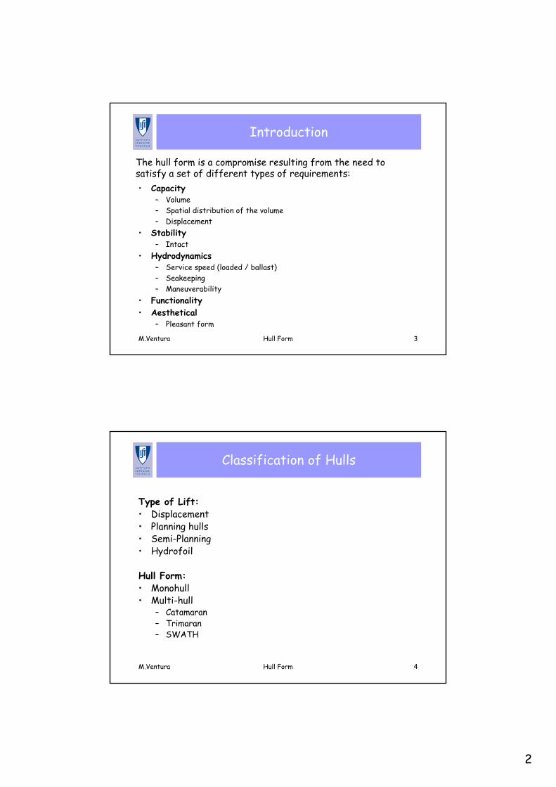
Type of Lift:• Displacement• Planning hulls• Semi-Planning• Hydrofoil
Hull Form:• Monohull• Multi-hull
– Catamaran– Trimaran– SWATH
3
M.Ventura Hull Form 5
Types of Lift
M.Ventura Hull Form 6
Displacement Hulls (1)
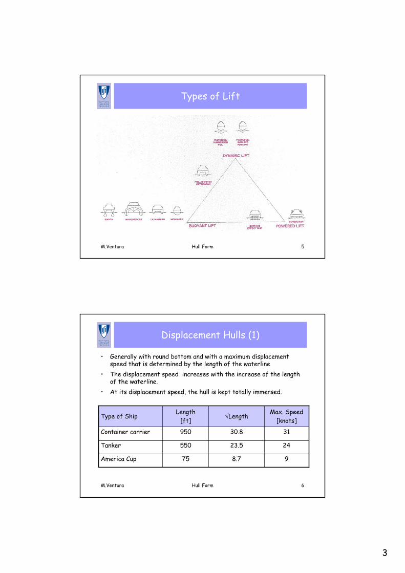
• Generally with round bottom and with a maximum displacement speed that is determined by the length of the waterline
• The displacement speed increases with the increase of the length of the waterline.
• At its displacement speed, the hull is kept totally immersed.
98.775America Cup
2423.5550Tanker
3130.8950Container carrier
Max. Speed[knots]
√LengthLength
[ft]Type of Ship
4
M.Ventura Hull Form 7
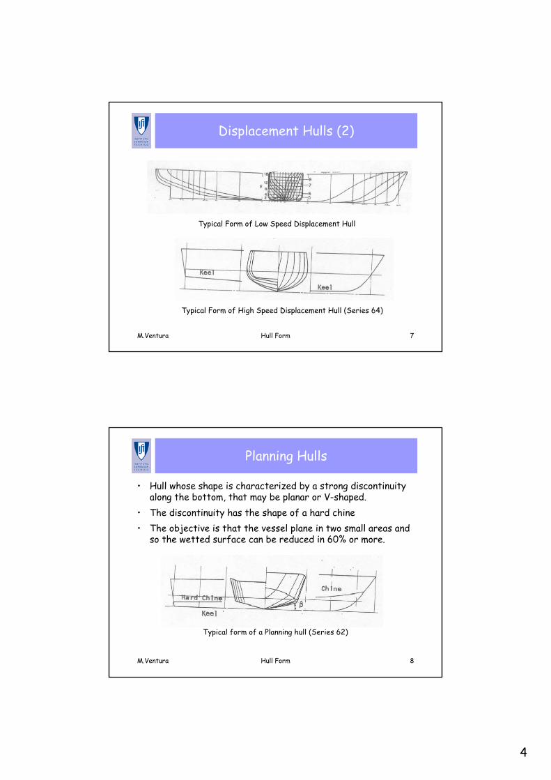
Displacement Hulls (2)
Typical Form of High Speed Displacement Hull (Series 64)
Typical Form of Low Speed Displacement Hull
M.Ventura Hull Form 8
Planning Hulls
• Hull whose shape is characterized by a strong discontinuity along the bottom, that may be planar or V-shaped.
• The discontinuity has the shape of a hard chine• The objective is that the vessel plane in two small areas and
so the wetted surface can be reduced in 60% or more.
Typical form of a Planning hull (Series 62)
5
M.Ventura Hull Form 9
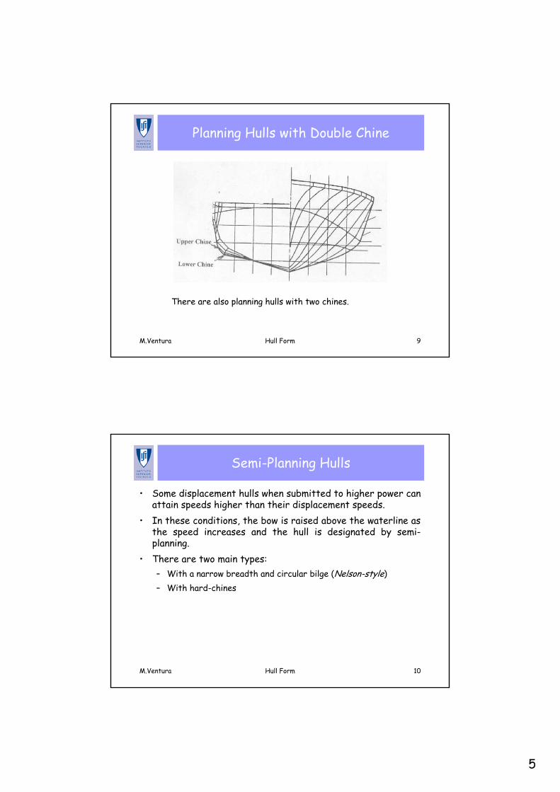
Planning Hulls with Double Chine
There are also planning hulls with two chines.
M.Ventura Hull Form 10
Semi-Planning Hulls
• Some displacement hulls when submitted to higher power can attain speeds higher than their displacement speeds.
• In these conditions, the bow is raised above the waterline as the speed increases and the hull is designated by semi-planning.
• There are two main types: – With a narrow breadth and circular bilge (Nelson-style)– With hard-chines
6
M.Ventura Hull Form 11
Hydrofoil
• The application of foils under the hull in order to obtain a lift that, at higher speeds, allows the hull to raise above the water reducing the resistance.
• The first hydrofoil was designed by the Italian Forlanini in 1906.
M.Ventura Hull Form 12
Multi-Hulls
• Catamaran
• Trimaran
• SWATH
7
M.Ventura Hull Form 13
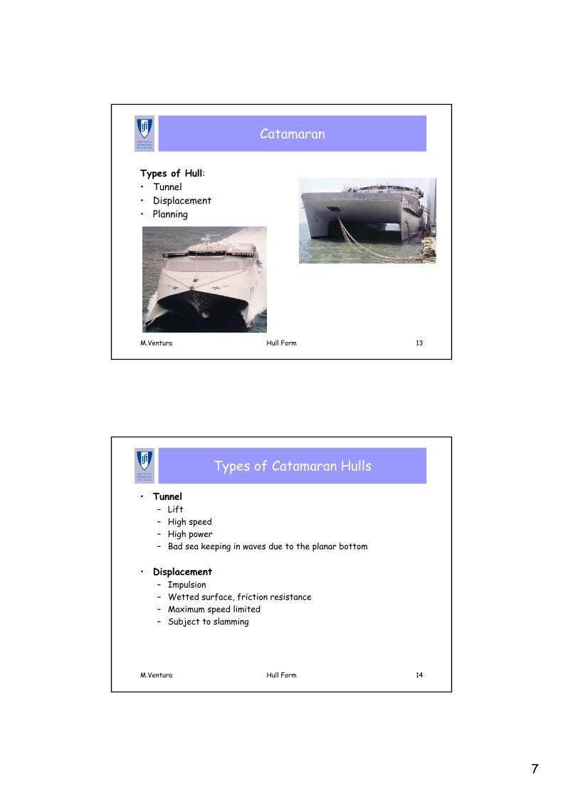
Catamaran
Types of Hull:• Tunnel• Displacement• Planning
M.Ventura Hull Form 14
Types of Catamaran Hulls
• Tunnel– Lift– High speed– High power– Bad sea keeping in waves due to the planar bottom
• Displacement– Impulsion– Wetted surface, friction resistance– Maximum speed limited– Subject to slamming
8
M.Ventura Hull Form 15
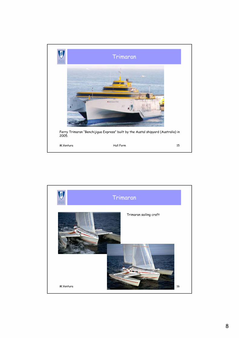
Trimaran
Ferry Trimaran “Benchijigua Express” built by the Austal shipyard (Australia) in2005.
M.Ventura Hull Form 16
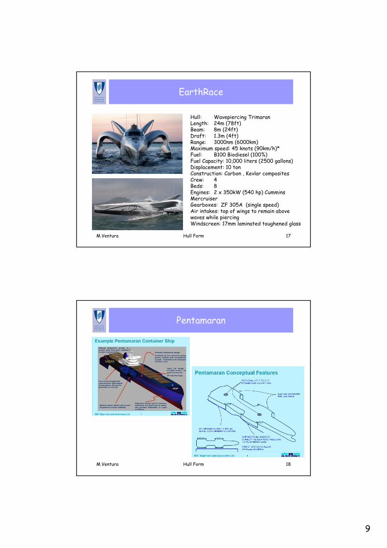
Trimaran
Trimaran sailing craft
9
M.Ventura Hull Form 17
EarthRace
Hull: Wavepiercing TrimaranLength: 24m (78ft) Beam: 8m (24ft) Draft: 1.3m (4ft) Range: 3000nm (6000km) Maximum speed: 45 knots (90km/h)* Fuel: B100 Biodiesel (100%) Fuel Capacity: 10,000 liters (2500 gallons) Displacement: 10 ton Construction: Carbon , Kevlar composites Crew: 4 Beds: 8 Engines: 2 x 350kW (540 hp) Cummins MercruiserGearboxes: ZF 305A (single speed) Air intakes: top of wings to remain above waves while piercing Windscreen: 17mm laminated toughened glass
M.Ventura Hull Form 18
Pentamaran
10
M.Ventura Hull Form 19
Evolution of the Pentamaran
• Patented on September 1996 - Patent expires on September 2016• Development and tank tests ADX 1996-1998• 11 technical papers published (1997 - 2003)• MARAD (USA) Sealift Development and tank tests 1998• Fast sealift ship DER on 1998• Project “ADX Express” 1999-2000 Fast Transatlantic container
service• IZAR signs license on September 2001 – license exclusive for Ro-
Ro and Ro-Pax in Europe• 2003 first contract for ship in IZAR with Buquebus – building
started on 2004• July 2003 concept of frigate F5• September 2003 IZAR renews license
M.Ventura Hull Form 20
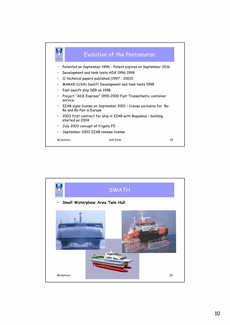
SWATH
• Small Waterplane Area Twin Hull
11
M.Ventura Hull Form 21
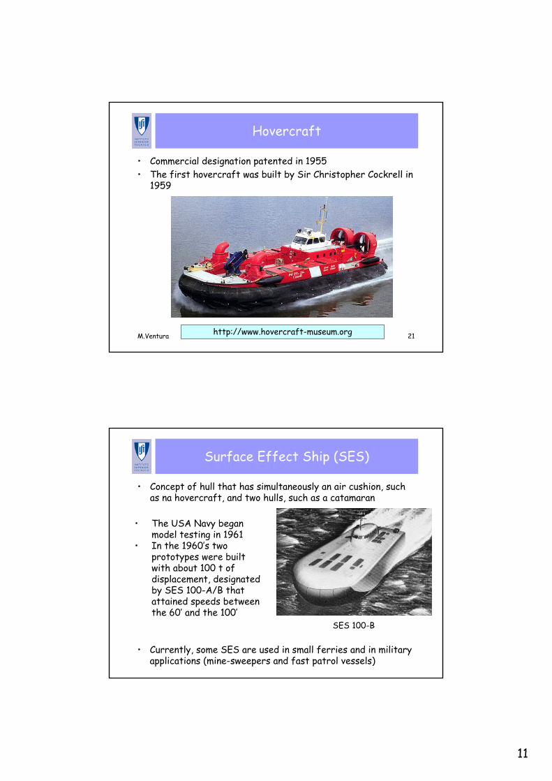
Hovercraft
• Commercial designation patented in 1955 • The first hovercraft was built by Sir Christopher Cockrell in
1959
http://www.hovercraft-museum.org
M.Ventura Hull Form 22
Surface Effect Ship (SES)
• Concept of hull that has simultaneously an air cushion, such as na hovercraft, and two hulls, such as a catamaran
• The USA Navy began model testing in 1961
• In the 1960’s two prototypes were built with about 100 t of displacement, designated by SES 100-A/B that attained speeds between the 60’ and the 100’
SES 100-B
• Currently, some SES are used in small ferries and in military applications (mine-sweepers and fast patrol vessels)
12
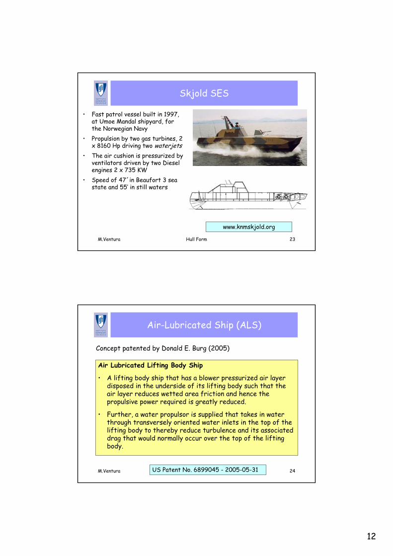
M.Ventura Hull Form 23
Skjold SES
• Fast patrol vessel built in 1997, at Umoe Mandal shipyard, for the Norwegian Navy
• Propulsion by two gas turbines, 2 x 8160 Hp driving two waterjets
• The air cushion is pressurized by ventilators driven by two Diesel engines 2 x 735 KW
• Speed of 47´in Beaufort 3 sea state and 55’ in still waters
www.knmskjold.org
M.Ventura Hull Form 24
Air-Lubricated Ship (ALS)
Air Lubricated Lifting Body Ship
• A lifting body ship that has a blower pressurized air layer disposed in the underside of its lifting body such that the air layer reduces wetted area friction and hence the propulsive power required is greatly reduced.
• Further, a water propulsor is supplied that takes in water through transversely oriented water inlets in the top of the lifting body to thereby reduce turbulence and its associated drag that would normally occur over the top of the lifting body.
US Patent No. 6899045 - 2005-05-31
Concept patented by Donald E. Burg (2005)
13
M.Ventura Hull Form 25
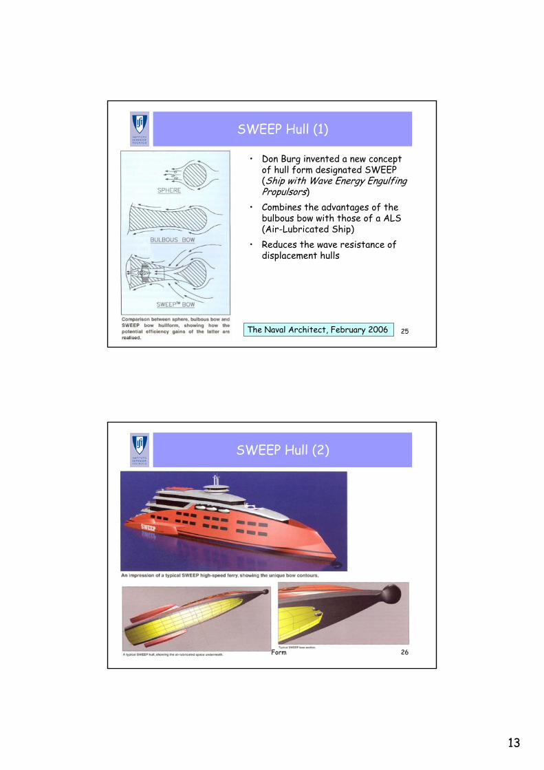
SWEEP Hull (1)
• Don Burg invented a new concept of hull form designated SWEEP (Ship with Wave Energy Engulfing Propulsors)
• Combines the advantages of the bulbous bow with those of a ALS (Air-Lubricated Ship)
• Reduces the wave resistance of displacement hulls
The Naval Architect, February 2006
M.Ventura Hull Form 26
SWEEP Hull (2)
14
Development of the Hull Form
M.Ventura Hull Form 28
Development of the Hull Form
Methods of hull form development:• Systematic Series • Direct development from main lines• Alteration of parent hull form
15
M.Ventura Hull Form 29
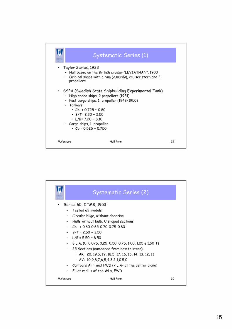
Systematic Series (1)
• Taylor Series, 1933– Hull based on the British cruiser “LEVIATHAN”, 1900– Original shape with a ram (esporão), cruiser stern and 2
propellers
• SSPA (Swedish State Shipbuilding Experimental Tank)– High speed ships, 2 propellers (1951)– Fast cargo ships, 1 propeller (1948/1950)– Tankers
• Cb = 0.725 ~ 0.80• B/T= 2.30 ~ 2.50• L/B= 7.20 ~ 8.10
– Cargo ships, 1 propeller• Cb = 0.525 ~ 0.750
M.Ventura Hull Form 30
Systematic Series (2)
• Series 60, DTMB, 1953– Tested 62 models– Circular bilge, without deadrise– Hulls without bulb, U shaped sections– Cb = 0.60-0.65-0.70-0.75-0.80– B/T = 2.50 ~ 3.50– L/B = 5.50 ~ 8.50– 8 L.A. (0, 0.075, 0.25, 0.50, 0.75, 1.00, 1.25 e 1.50 T)– 25 Sections (numbered from bow to stern):
• AR: 20, 19.5, 19, 18.5, 17, 16, 15, 14, 13, 12, 11 • AV: 10,9,8,7,6,5,4,3,2,1,0.5,0
– Contours AFT and FWD (7 L.A- at the center plane)– Fillet radius of the WLs, FWD
16
M.Ventura Hull Form 31
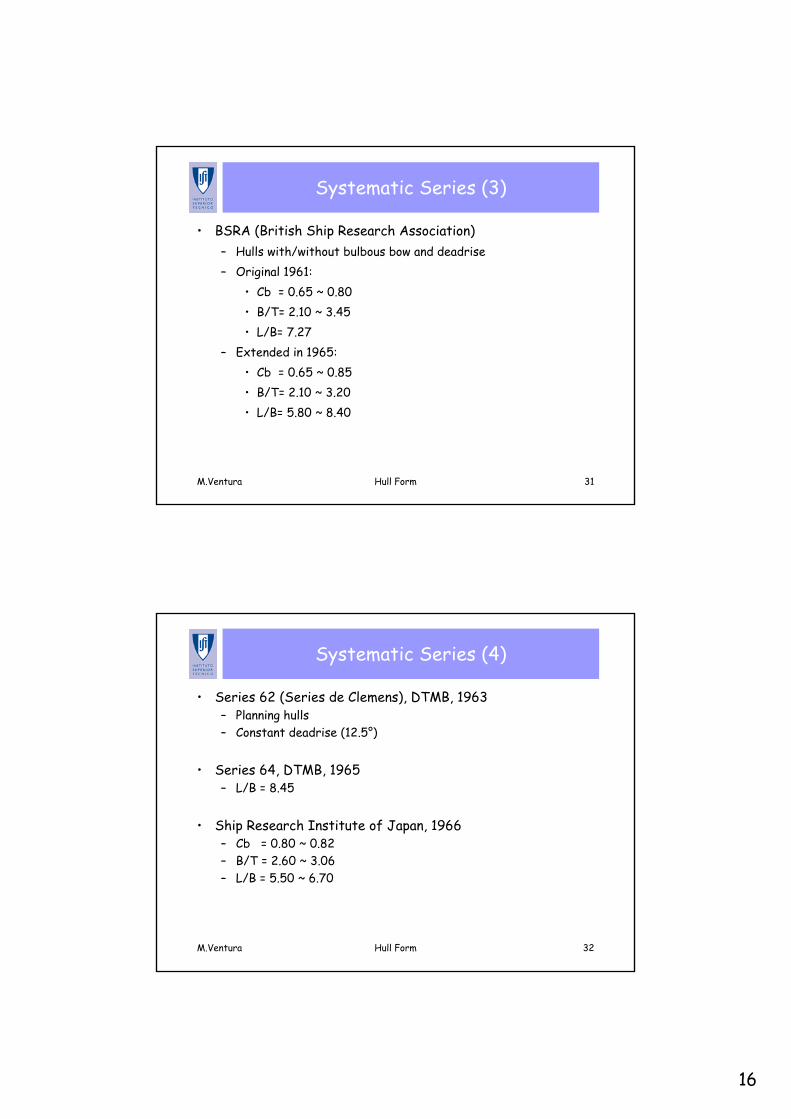
Systematic Series (3)
• BSRA (British Ship Research Association)– Hulls with/without bulbous bow and deadrise– Original 1961:
• Cb = 0.65 ~ 0.80• B/T= 2.10 ~ 3.45• L/B= 7.27
– Extended in 1965:• Cb = 0.65 ~ 0.85• B/T= 2.10 ~ 3.20• L/B= 5.80 ~ 8.40
M.Ventura Hull Form 32
Systematic Series (4)
• Series 62 (Series de Clemens), DTMB, 1963– Planning hulls– Constant deadrise (12.5°)
• Series 64, DTMB, 1965– L/B = 8.45
• Ship Research Institute of Japan, 1966– Cb = 0.80 ~ 0.82– B/T = 2.60 ~ 3.06– L/B = 5.50 ~ 6.70
17
M.Ventura Hull Form 33
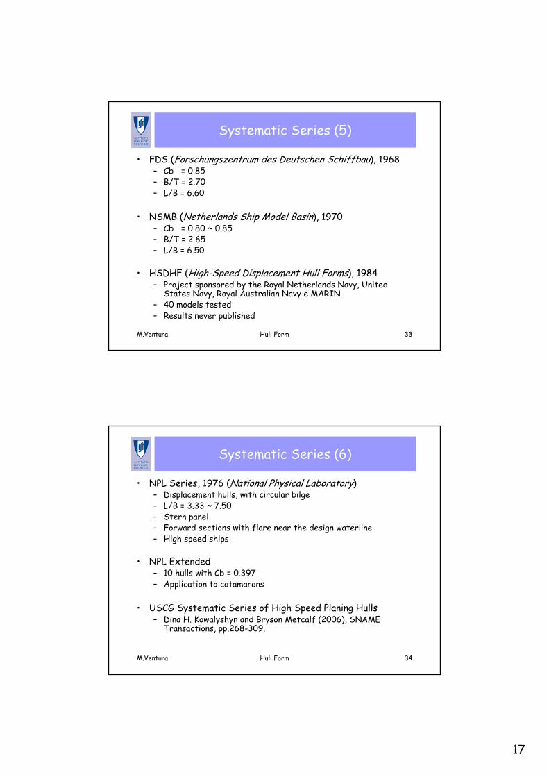
Systematic Series (5)
• FDS (Forschungszentrum des Deutschen Schiffbau), 1968– Cb = 0.85– B/T = 2.70– L/B = 6.60
• NSMB (Netherlands Ship Model Basin), 1970– Cb = 0.80 ~ 0.85– B/T = 2.65– L/B = 6.50
• HSDHF (High-Speed Displacement Hull Forms), 1984– Project sponsored by the Royal Netherlands Navy, United
States Navy, Royal Australian Navy e MARIN– 40 models tested– Results never published
M.Ventura Hull Form 34
Systematic Series (6)
• NPL Series, 1976 (National Physical Laboratory)– Displacement hulls, with circular bilge– L/B = 3.33 ~ 7.50– Stern panel– Forward sections with flare near the design waterline– High speed ships
• NPL Extended– 10 hulls with Cb = 0.397– Application to catamarans
• USCG Systematic Series of High Speed Planing Hulls– Dina H. Kowalyshyn and Bryson Metcalf (2006), SNAME
Transactions, pp.268-309.
18
M.Ventura Hull Form 35
Systematic Series (7)
• MARAD Systematic Series of Full-Form Ship Models, 1987– Low value of L/B– High value of B/T– Cb = 0.80 ~ 0.875– B/T = 3.00 ~ 4.75– L/B = 4.50 ~ 6.50
• AMECRC (Australian Maritime Engineering Cooperative Research Centre), 1998– Based on the HSDHF– Cb = 0.395 ~ 0.5– L/B = 6.0 ~ 8.0– B/T = 2.5 ~ 4.0– Used in multi-hulls
M.Ventura Hull Form 36
Systematic Series – Sailing Vessels
• Delft Systematic Series, Modern Yacht Conference (1998) or Chesapeake Symposium (1999) ????
19
M.Ventura Hull Form 37
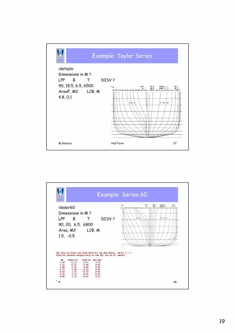
Example: Taylor Series
idetayloDimensions in M ?LPP B T DISV ?90, 18.5, 6.5, 6500AreaF, M2 LCB, M4.8, 0.1
M.Ventura Hull Form 38
Example: Series 60
ideser60Dimensions in M ?LPP B T DISV ?90, 20, 6.5, 6800Area, M2 LCB, M1.5, -0.5
20
M.Ventura Hull Form 39
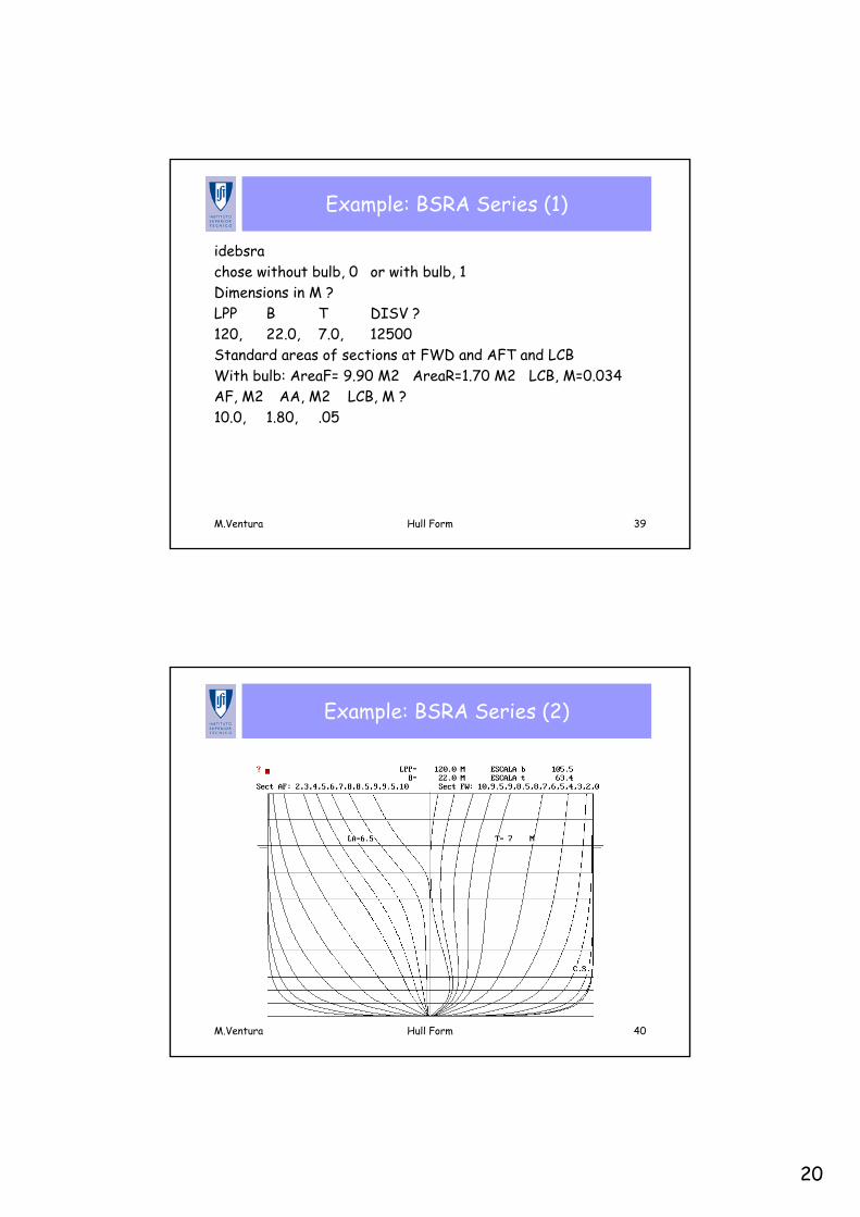
Example: BSRA Series (1)
idebsrachose without bulb, 0 or with bulb, 1Dimensions in M ?LPP B T DISV ?120, 22.0, 7.0, 12500Standard areas of sections at FWD and AFT and LCBWith bulb: AreaF= 9.90 M2 AreaR=1.70 M2 LCB, M=0.034AF, M2 AA, M2 LCB, M ?10.0, 1.80, .05
M.Ventura Hull Form 40
Example: BSRA Series (2)
21
M.Ventura Hull Form 41
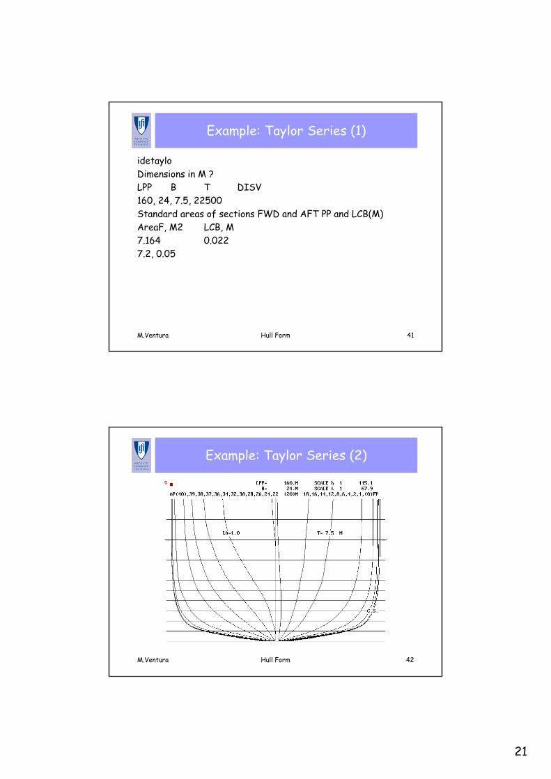
Example: Taylor Series (1)
idetayloDimensions in M ?LPP B T DISV160, 24, 7.5, 22500Standard areas of sections FWD and AFT PP and LCB(M)AreaF, M2 LCB, M7.164 0.0227.2, 0.05
M.Ventura Hull Form 42
Example: Taylor Series (2)
22
Direct Development of the Hull Form
Manuel Ventura
Ship Design I
MSC in Marine Engineering and Naval Architecture
M.Ventura Hull Form 44
Data for Hull Form Development
• The hull form can be defined from a set of parameters and a set of main curves
• The parameters are the main dimensions and some hydrostatic characteristics (Ex.: ∆, Lcb, form coefficients, etc.)
• The main dimensions are:– Length between perpendiculars (Lpp)– Breadth, molded (B)– Depth (D)– Design draught (T)
• The form coefficients are:– Block Coefficient (CB)– Prismatic Coefficient (CP)– Midship Section Coefficient (CM)– Waterplane Area Coefficient (CWP)
23
M.Ventura Hull Form 45
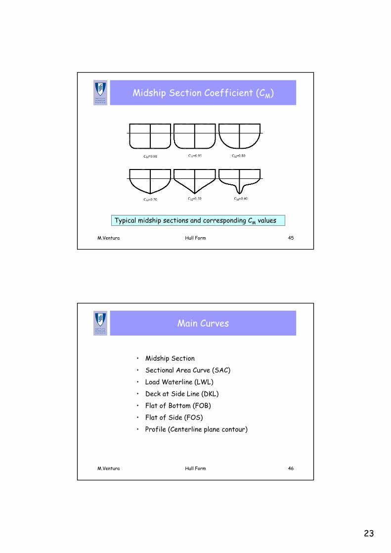
Midship Section Coefficient (CM)
Typical midship sections and corresponding CM values
M.Ventura Hull Form 46
Main Curves
• Midship Section
• Sectional Area Curve (SAC)
• Load Waterline (LWL)
• Deck at Side Line (DKL)
• Flat of Bottom (FOB)
• Flat of Side (FOS)
• Profile (Centerline plane contour)
24
M.Ventura Hull Form 47
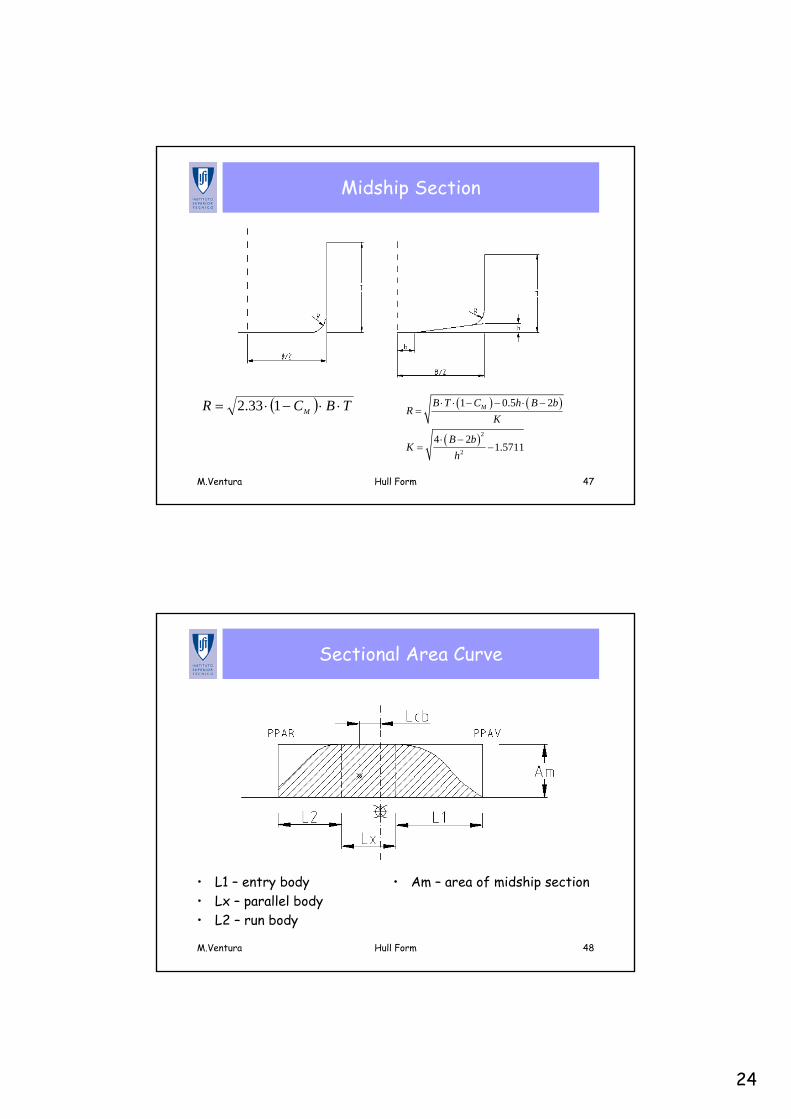
Midship Section
( ) TBCR M ⋅⋅−⋅= 133.2 ( ) ( )
( )2
2
1 0.5 2
4 21.5711
MB T C h B bR
K
B bK
h
⋅ ⋅ − − ⋅ −=
⋅ −= −
M.Ventura Hull Form 48
Sectional Area Curve
• L1 – entry body• Lx – parallel body• L2 – run body
• Am – area of midship section
25
M.Ventura Hull Form 49
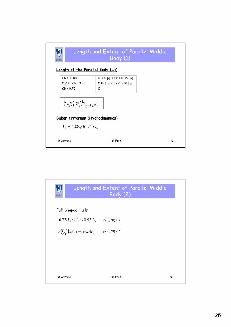
Length and Extent of Parallel Middle Body (1)
L = L1 + LX + L2L.CP = L.Cp1 + LX + L2.Cp2
Cb ≥ 0.80 0.30 Lpp ≤ Lx ≤ 0.35 Lpp0.70 ≤ Cb < 0.80 0.15 Lpp ≤ Lx ≤ 0.20 LppCb < 0.70 0
MCTBL ⋅⋅= 08.42
Length of the Parallel Body (Lx)
Baker Criterium (Hydrodinamics)
M.Ventura Hull Form 50
Length and Extent of Parallel Middle Body (2)
Full Shaped Hulls
p/ (L/B) = 7
p/ (L/B) < 7
2 1 20.75 0.95L L L≤ ≤
( ) XLBL δδ %11.0 ⇒=
26
M.Ventura Hull Form 51
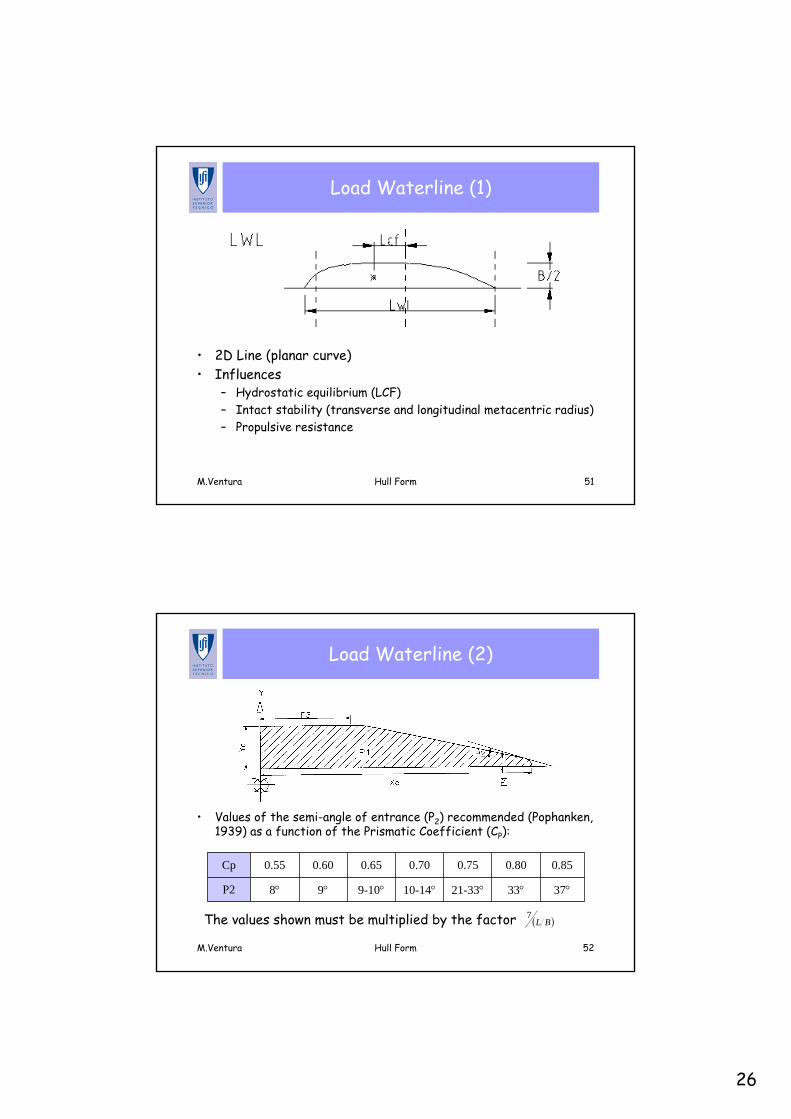
Load Waterline (1)
• 2D Line (planar curve)• Influences
– Hydrostatic equilibrium (LCF)– Intact stability (transverse and longitudinal metacentric radius)– Propulsive resistance
M.Ventura Hull Form 52
Load Waterline (2)
• Values of the semi-angle of entrance (P2) recommended (Pophanken, 1939) as a function of the Prismatic Coefficient (CP):
37°33°21-33°10-14°9-10°9°8°P2
0.850.800.750.700.650.600.55Cp
The values shown must be multiplied by the factor ( )BL7
27
M.Ventura Hull Form 53
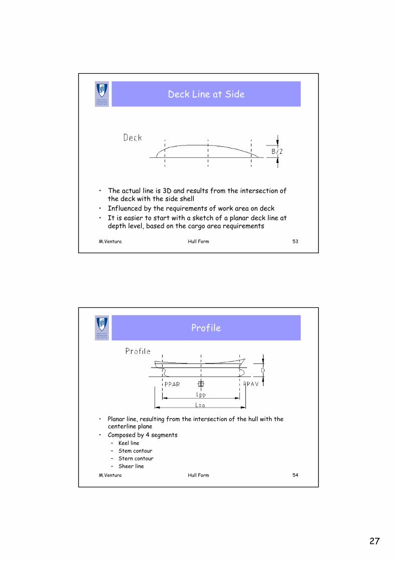
Deck Line at Side
• The actual line is 3D and results from the intersection of the deck with the side shell
• Influenced by the requirements of work area on deck• It is easier to start with a sketch of a planar deck line at
depth level, based on the cargo area requirements
M.Ventura Hull Form 54
Profile
• Planar line, resulting from the intersection of the hull with the centerline plane
• Composed by 4 segments– Keel line– Stem contour– Stern contour– Sheer line
28
M.Ventura Hull Form 55
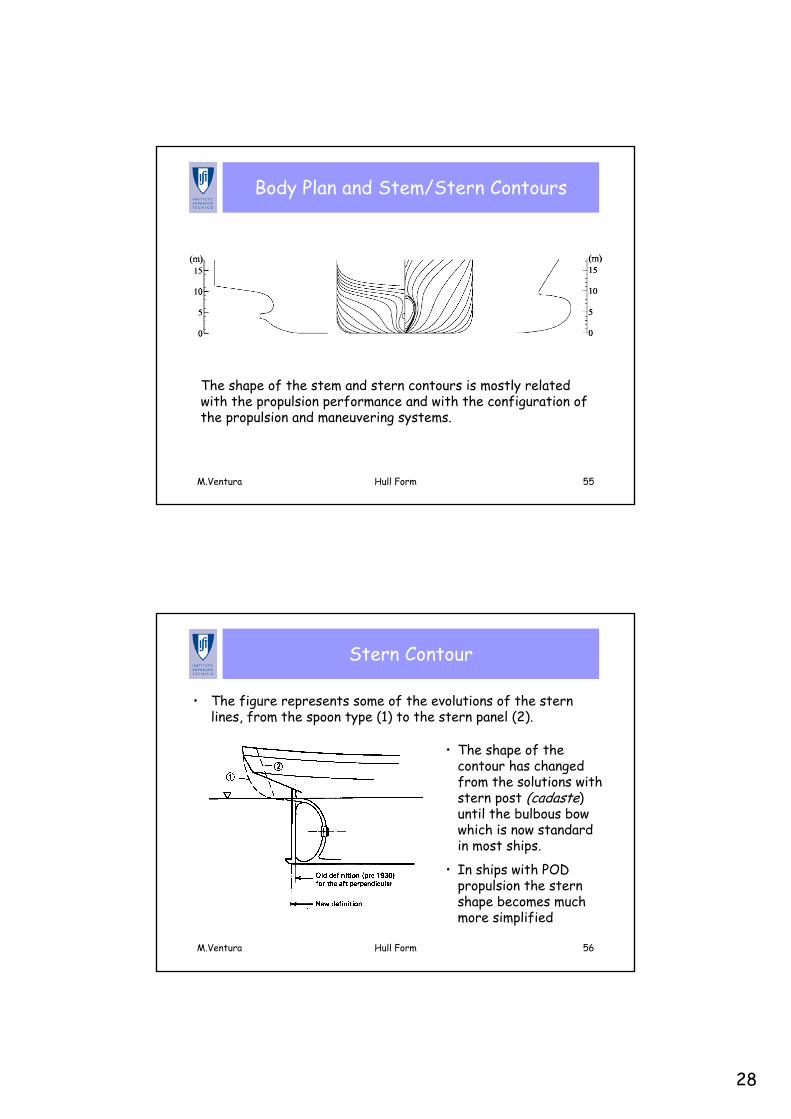
Body Plan and Stem/Stern Contours
The shape of the stem and stern contours is mostly related with the propulsion performance and with the configuration of the propulsion and maneuvering systems.
M.Ventura Hull Form 56
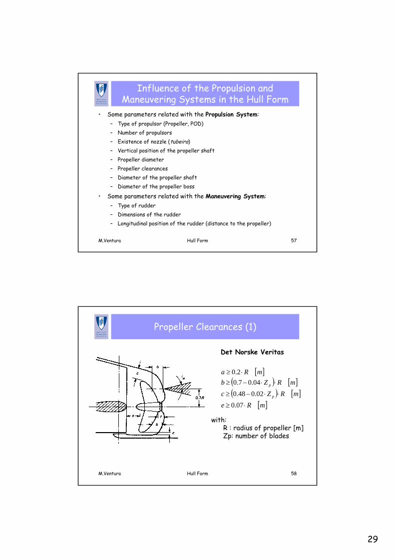
Stern Contour
• The figure represents some of the evolutions of the stern lines, from the spoon type (1) to the stern panel (2).
• The shape of the contour has changed from the solutions with stern post (cadaste) until the bulbous bow which is now standard in most ships.
• In ships with POD propulsion the stern shape becomes much more simplified
29
M.Ventura Hull Form 57
Influence of the Propulsion and Maneuvering Systems in the Hull Form
• Some parameters related with the Propulsion System:– Type of propulsor (Propeller, POD)– Number of propulsors– Existence of nozzle (tubeira)– Vertical position of the propeller shaft– Propeller diameter– Propeller clearances– Diameter of the propeller shaft– Diameter of the propeller boss
• Some parameters related with the Maneuvering System:– Type of rudder– Dimensions of the rudder– Longitudinal position of the rudder (distance to the propeller)
M.Ventura Hull Form 58
Propeller Clearances (1)
Det Norske Veritas
[ ]( ) [ ]( ) [ ]
[ ]mRemRZc
mRZbmRa
p
p
⋅≥
⋅⋅−≥
⋅⋅−≥⋅≥
07.002.048.0
04.07.02.0
with:R : radius of propeller [m]Zp: number of blades
30
M.Ventura Hull Form 59
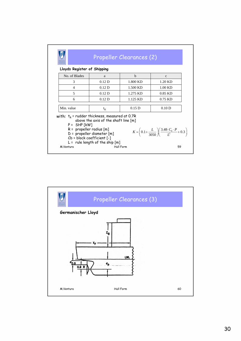
Propeller Clearances (2)
Lloyds Register of Shipping
0.75 KD1.125 KD0.12 D60.85 KD1.275 KD0.12 D51.00 KD1.500 KD0.12 D41.20 KD1.800 KD0.12 D3
cbaNo. of Blades
0.10 D0.15 DtRMin. value
with:
3
3.480.1 0.33050
bC PLKL⋅ ⋅⎛ ⎞⎛ ⎞= + +⎜ ⎟ ⎜ ⎟
⎝ ⎠ ⎝ ⎠
tR = rudder thickness, measured at 0.7R above the axis of the shaft line [m]
P = SHP [kW]R = propeller radius [m]D = propeller diameter [m]Cb = block coefficient [-]L = rule length of the ship [m]
M.Ventura Hull Form 60
Propeller Clearances (3)
Germanischer Lloyd
31
M.Ventura Hull Form 61
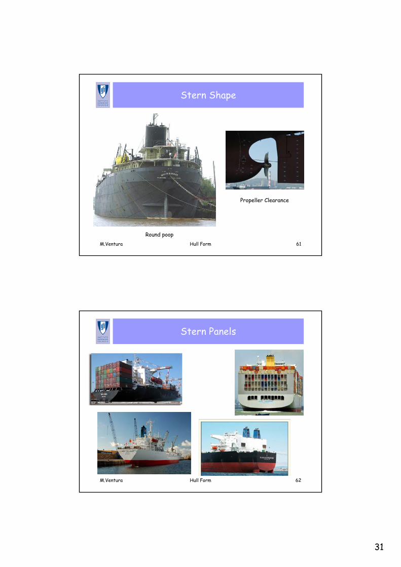
Stern Shape
Propeller Clearance
Round poop
M.Ventura Hull Form 62
Stern Panels
32
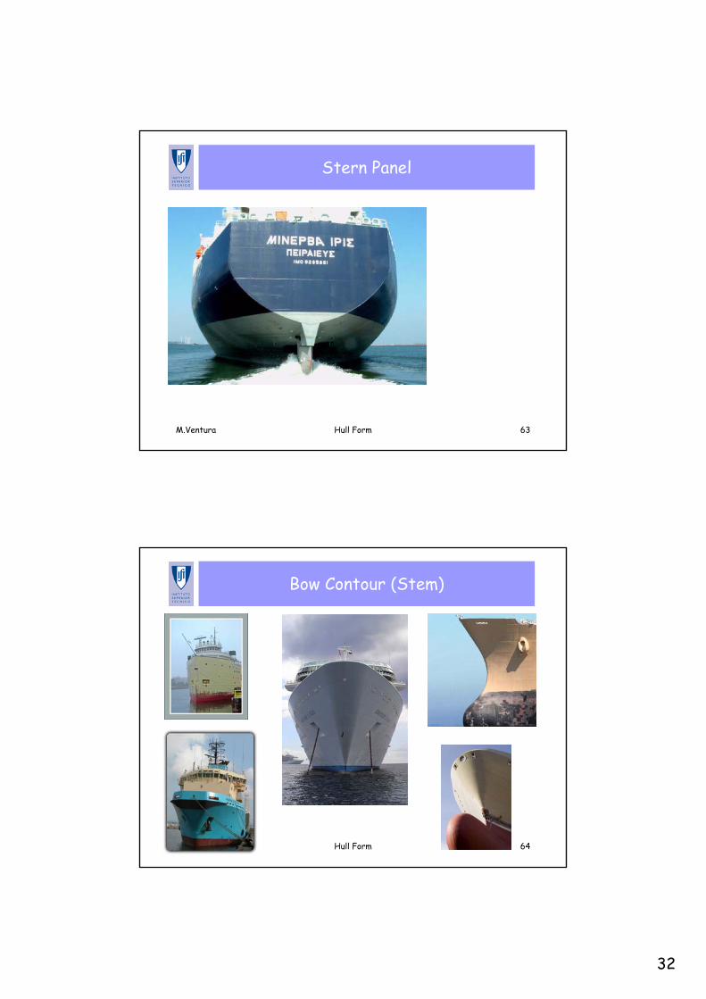
M.Ventura Hull Form 63
Stern Panel
M.Ventura Hull Form 64
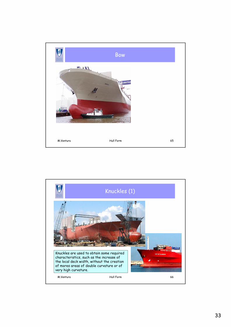
Bow Contour (Stem)
33
M.Ventura Hull Form 65
Bow
M.Ventura Hull Form 66
Knuckles (1)
Knuckles are used to obtain some required characteristics, such as the increase of the local deck width, without the creation of mores areas of double curvature or of very high curvature.
34
M.Ventura Hull Form 67
Knuckles (2)
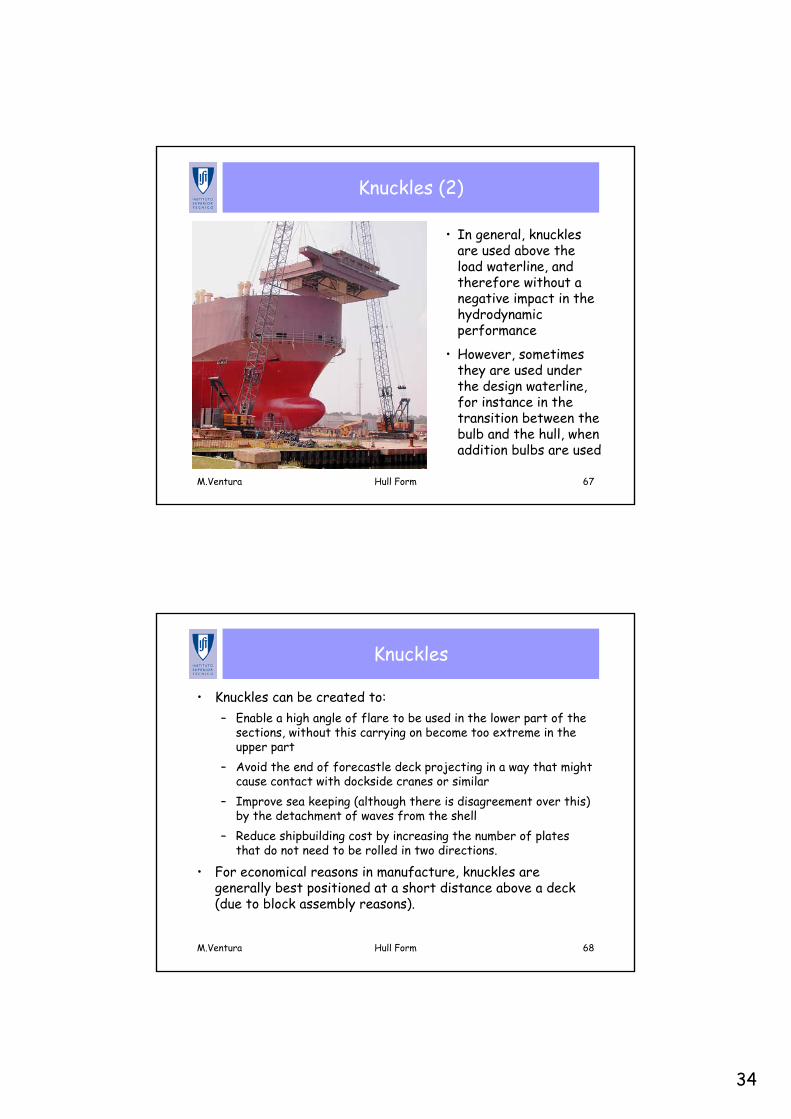
• In general, knuckles are used above the load waterline, and therefore without a negative impact in the hydrodynamic performance
• However, sometimes they are used under the design waterline, for instance in the transition between the bulb and the hull, when addition bulbs are used
M.Ventura Hull Form 68
Knuckles
• Knuckles can be created to:– Enable a high angle of flare to be used in the lower part of the
sections, without this carrying on become too extreme in the upper part
– Avoid the end of forecastle deck projecting in a way that might cause contact with dockside cranes or similar
– Improve sea keeping (although there is disagreement over this) by the detachment of waves from the shell
– Reduce shipbuilding cost by increasing the number of plates that do not need to be rolled in two directions.
• For economical reasons in manufacture, knuckles are generally best positioned at a short distance above a deck (due to block assembly reasons).
35
M.Ventura Hull Form 69
Elliptical Bow (1)
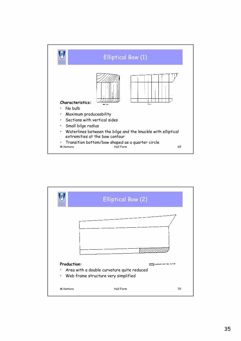
Characteristics:• No bulb• Maximum produceability• Sections with vertical sides• Small bilge radius• Waterlines between the bilge and the knuckle with elliptical
extremities at the bow contour• Transition bottom/bow shaped as a quarter circle
M.Ventura Hull Form 70
Elliptical Bow (2)
Production:• Area with a double curvature quite reduced• Web frame structure very simplified
36
M.Ventura Hull Form 71
Conical Bow (1)
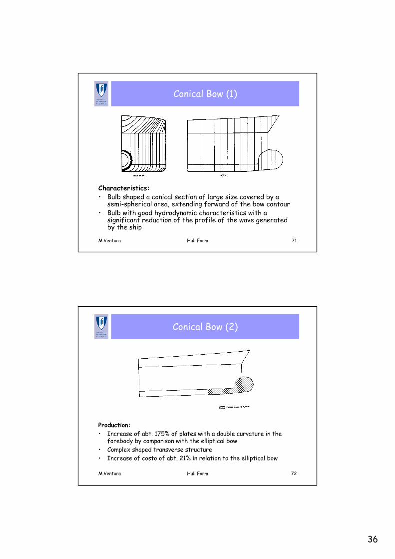
Characteristics:• Bulb shaped a conical section of large size covered by a
semi-spherical area, extending forward of the bow contour• Bulb with good hydrodynamic characteristics with a
significant reduction of the profile of the wave generated by the ship
M.Ventura Hull Form 72
Conical Bow (2)
Production:• Increase of abt. 175% of plates with a double curvature in the
forebody by comparison with the elliptical bow• Complex shaped transverse structure• Increase of costo of abt. 21% in relation to the elliptical bow
37
M.Ventura Hull Form 73
Spoon Type Bow (1)
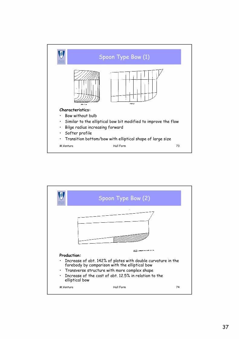
Characteristics:• Bow without bulb• Similar to the elliptical bow bit modified to improve the flow• Bilge radius increasing forward• Softer profile• Transition bottom/bow with elliptical shape of large size
M.Ventura Hull Form 74
Spoon Type Bow (2)
Production:• Increase of abt. 142% of plates with double curvature in the
forebody by comparison with the elliptical bow• Transverse structure with more complex shape• Increase of the cost of abt. 12.5% in relation to the
elliptical bow
38
M.Ventura Hull Form 75
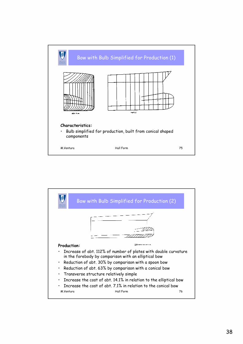
Bow with Bulb Simplified for Production (1)
Characteristics:• Bulb simplified for production, built from conical shaped
components
M.Ventura Hull Form 76
Bow with Bulb Simplified for Production (2)
Production:• Increase of abt. 112% of number of plates with double curvature
in the forebody by comparison with an elliptical bow• Reduction of abt. 30% by comparison with a spoon bow• Reduction of abt. 63% by comparison with a conical bow• Transverse structure relatively simple• Increase the cost of abt. 14.1% in relation to the elliptical bow • Increase the cost of abt. 7.1% in relation to the conical bow
39
M.Ventura Hull Form 77
Direct Development of the Hull Form
Main steps:• Sketch a load waterline• Draw a midship section and locate one copy in each end of
the parallel middle body • Draw three sections in the forebody and three sections in
the aftbody in such a way to obtain for each one the area defined in the Sectional Area Curve
• Create 2 waterlines from the intersections with the existing sections and fair the lines obtained
• Proceed with modifications of the initial sections until satisfactory faired lines are obtained
• Draw a longitudinal section and fair the line• Continue to create sections and waterlines by the same
process described above…
M.Ventura Hull Form 78
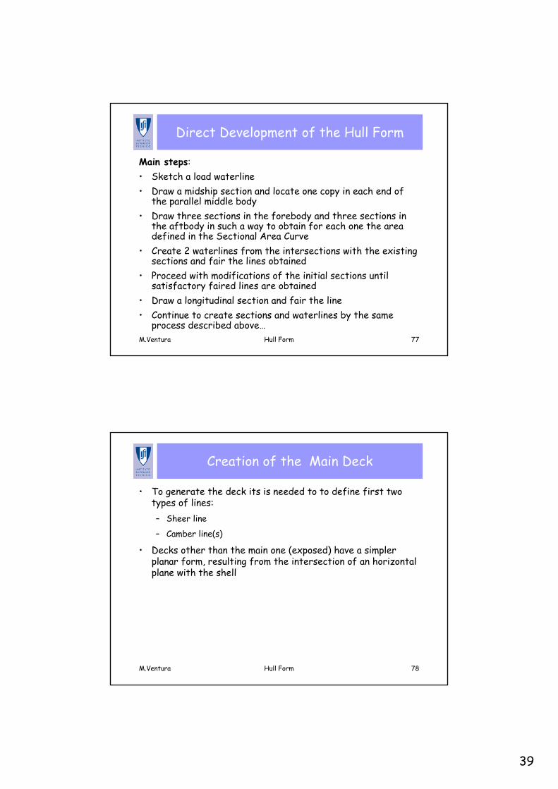
Creation of the Main Deck
• To generate the deck its is needed to to define first two types of lines:– Sheer line
– Camber line(s)
• Decks other than the main one (exposed) have a simpler planar form, resulting from the intersection of an horizontal plane with the shell
40
M.Ventura Hull Form 79
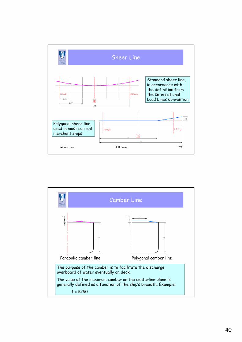
Sheer Line
Standard sheer line, in accordance with the definition from the International Load Lines Convention
Polygonal sheer line, used in most current merchant ships
M.Ventura Hull Form 80
Camber Line
Parabolic camber line Polygonal camber line
The purpose of the camber is to facilitate the discharge overboard of water eventually on deck.
The value of the maximum camber on the centerline plane is generally defined as a function of the ship’s breadth. Example:
f = B/50
41
M.Ventura Hull Form 81
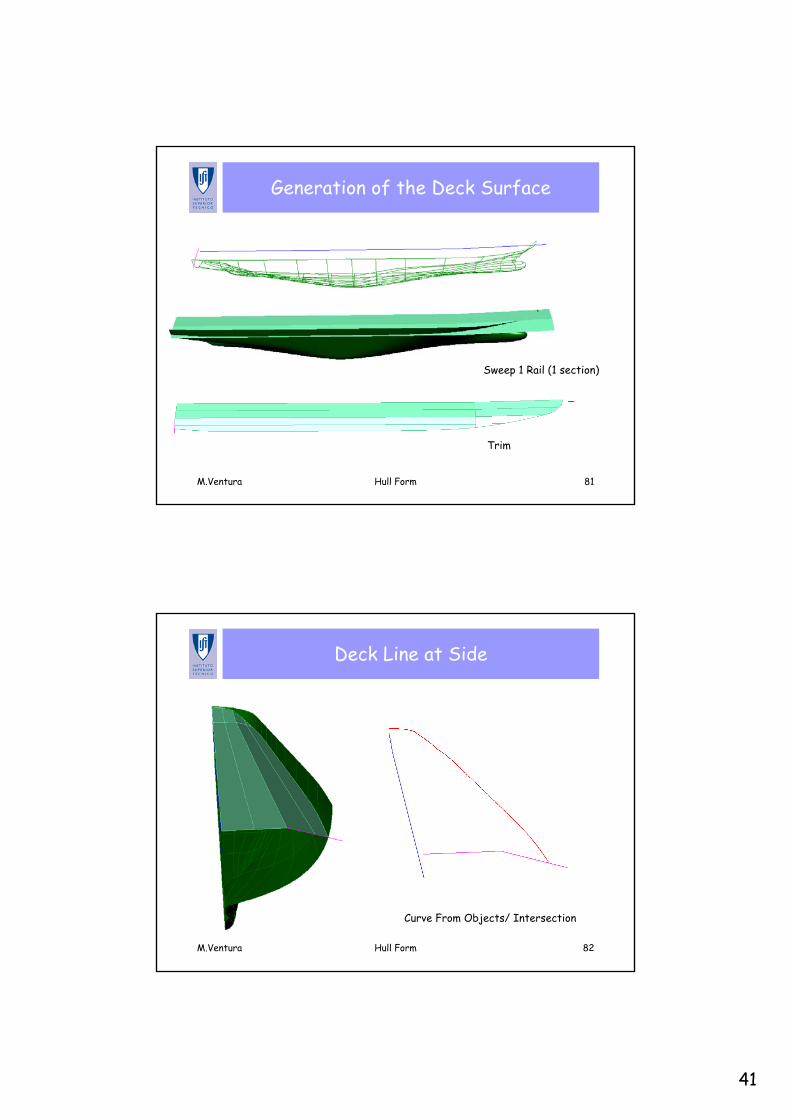
Generation of the Deck Surface
Sweep 1 Rail (1 section)
Trim
M.Ventura Hull Form 82
Deck Line at Side
Curve From Objects/ Intersection
42
M.Ventura Hull Form 83
Openings on the Shell
• The small openings, such as those from sea chests (caixasde mar), are not relevant for the Lines Plan
• The openings of larger sizes shell be located in the Lines Plan– Thrusters tunnels– Intersection of the hawse pipes (escovéns) with the shell
M.Ventura Hull Form 84
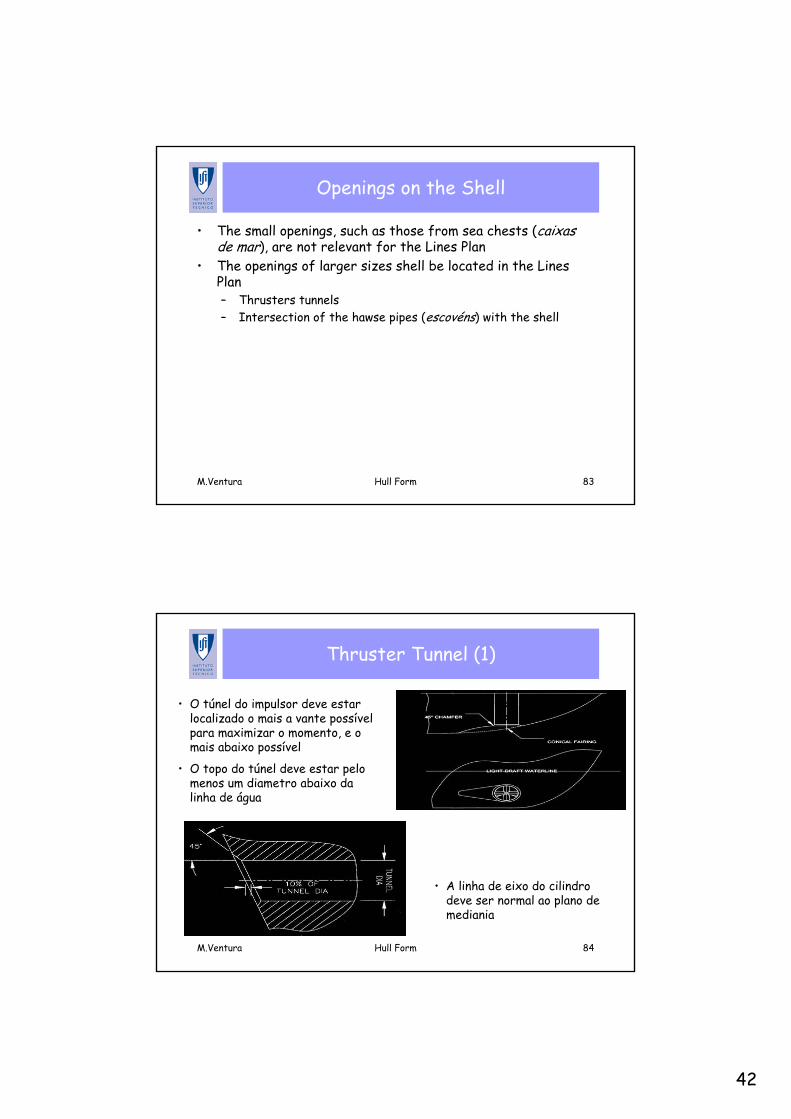
Thruster Tunnel (1)
• O túnel do impulsor deve estarlocalizado o mais a vante possívelpara maximizar o momento, e o mais abaixo possível
• O topo do túnel deve estar pelomenos um diametro abaixo da linha de água
• A linha de eixo do cilindro deve ser normal ao plano de mediania
43
M.Ventura Hull Form 85
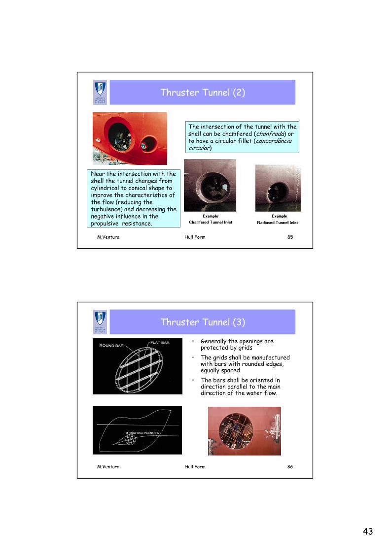
Thruster Tunnel (2)
Near the intersection with the shell the tunnel changes from cylindrical to conical shape to improve the characteristics of the flow (reducing the turbulence) and decreasing the negative influence in the propulsive resistance.
The intersection of the tunnel with the shell can be chamfered (chanfrada) or to have a circular fillet (concordânciacircular)
M.Ventura Hull Form 86
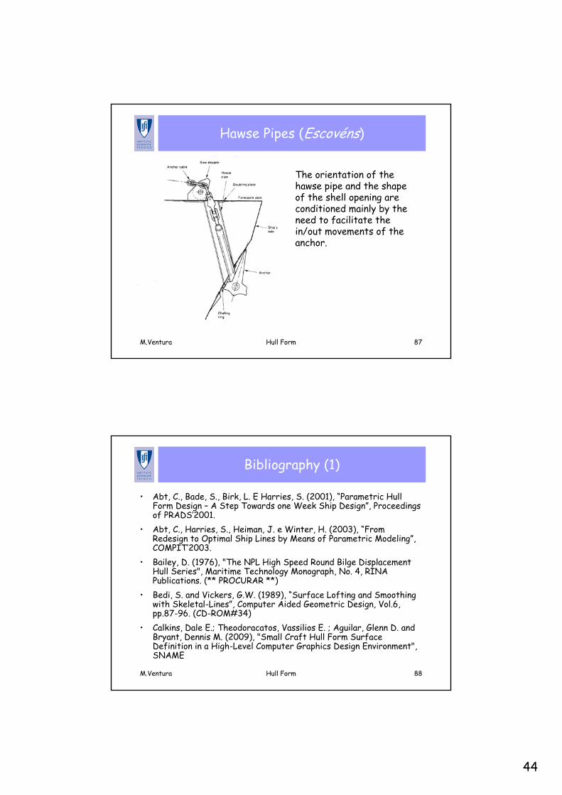
Thruster Tunnel (3)
• Generally the openings are protected by grids
• The grids shall be manufactured with bars with rounded edges, equally spaced
• The bars shall be oriented in direction parallel to the main direction of the water flow.
44
M.Ventura Hull Form 87
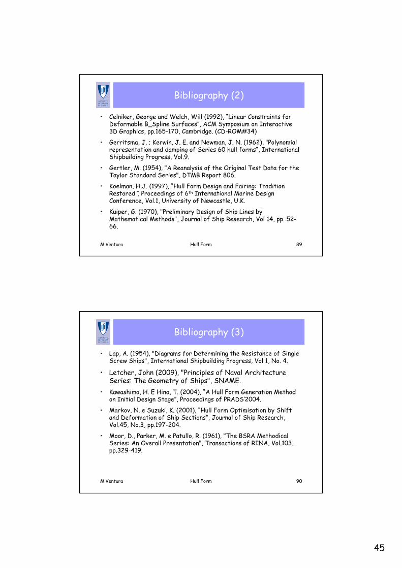
Hawse Pipes (Escovéns)
The orientation of the hawse pipe and the shape of the shell opening are conditioned mainly by the need to facilitate the in/out movements of the anchor.
M.Ventura Hull Form 88
Bibliography (1)
• Abt, C., Bade, S., Birk, L. E Harries, S. (2001), “Parametric Hull Form Design – A Step Towards one Week Ship Design”, Proceedings of PRADS’2001.
• Abt, C., Harries, S., Heiman, J. e Winter, H. (2003), “From Redesign to Optimal Ship Lines by Means of Parametric Modeling”, COMPIT’2003.
• Bailey, D. (1976), "The NPL High Speed Round Bilge Displacement Hull Series", Maritime Technology Monograph, No. 4, RINA Publications. (** PROCURAR **)
• Bedi, S. and Vickers, G.W. (1989), “Surface Lofting and Smoothing with Skeletal-Lines”, Computer Aided Geometric Design, Vol.6, pp.87-96. (CD-ROM#34)
• Calkins, Dale E.; Theodoracatos, Vassilios E. ; Aguilar, Glenn D. and Bryant, Dennis M. (2009), "Small Craft Hull Form Surface Definition in a High-Level Computer Graphics Design Environment", SNAME
45
M.Ventura Hull Form 89
Bibliography (2)
• Celniker, George and Welch, Will (1992), “Linear Constraints for Deformable B_Spline Surfaces”, ACM Symposium on Interactive 3D Graphics, pp.165-170, Cambridge. (CD-ROM#34)
• Gerritsma, J. ; Kerwin, J. E. and Newman, J. N. (1962), "Polynomial representation and damping of Series 60 hull forms“, International Shipbuilding Progress, Vol.9.
• Gertler, M. (1954), "A Reanalysis of the Original Test Data for the Taylor Standard Series", DTMB Report 806.
• Koelman, H.J. (1997), “Hull Form Design and Fairing: Tradition Restored”, Proceedings of 6th International Marine Design Conference, Vol.1, University of Newcastle, U.K.
• Kuiper, G. (1970), "Preliminary Design of Ship Lines by Mathematical Methods", Journal of Ship Research, Vol 14, pp. 52-66.
M.Ventura Hull Form 90
Bibliography (3)
• Lap, A. (1954), "Diagrams for Determining the Resistance of Single Screw Ships", International Shipbuilding Progress, Vol 1, No. 4.
• Letcher, John (2009), "Principles of Naval Architecture Series: The Geometry of Ships", SNAME.
• Kawashima, H. E Hino, T. (2004), “A Hull Form Generation Method on Initial Design Stage”, Proceedings of PRADS’2004.
• Markov, N. e Suzuki, K. (2001), “Hull Form Optimisation by Shift and Deformation of Ship Sections”, Journal of Ship Research, Vol.45, No.3, pp.197-204.
• Moor, D., Parker, M. e Patullo, R. (1961), "The BSRA Methodical Series: An Overall Presentation", Transactions of RINA, Vol.103,pp.329-419.
46
M.Ventura Hull Form 91
Bibliography (4)
• Nowacki, H., Creutz, G., and Munchmeyer, F. (1977), "Ship Lines Creation by Computer - Objectives, Methods and Results", First International Symposium on Computer-Aided Hull Surface Definition (SCAHD77), pp 1-18, SNAME, Anapolis, MD.
• Nowacki, H. and Reese, D. (1983), "Design and Fairing of Ship Surfaces", Surfaces in Computer Aided Geometric Design, North Holland, Eds. Barnhill, R. and Boehm, W., pp. 121-134.
O’Neill, Wiliam C. (????), “Hydrofoil Ship Design”. (CD-ROM#34)
• Pophanken, E. (1939), “Schiffbaukalender – Hilfsbuch derSchiffbauindustrie“, Deutch Verlagswerke, Berlin.
• Reed, A. and Nowacki, H. (1974), "Interactive Creation of Fair Ship Lines", Journal of Ship Research, Vol.18, pp.96-112.
M.Ventura Hull Form 92
Bibliography (5)
• Sabit, A. S. (1972), “An Analysis of the Series 60 Results Part I –Analysis of Forms and Resistance Results”, International Shipbuilding Progress, Vol..19, pp.81-97.Savitsky, Daniel (2003), “On the Subject of High-Speed Monohulls”, SNAME. (CD-ROM#34)
• Sha, O. Misra, S. E Gokarn, R. (2004), “Ship Hull Form Design – A Modular Approach”, Proceedings of PRADS’2004.
• Soding, H. and Rabien, U., "Hull Surface Design by Modifying an Existing Hull", First International Symposium on Computer-Aided Hull Surface Definition (SCAHD77), pp 19-29, SNAME, Anapolis, MD, 1977.
• Standerski, N. (1989), "The Generation of Ship Hulls With Given Design Parameters Using Tensor Product Surfaces", Theory and Practice of Geometric Modeling, Eds. Strasser, W. and Seidel, H., Springer Verlag, pp. 65-79.
47
M.Ventura Hull Form 93
Bibliography (6)
Holtrop, J. and Mennen, G. (1982), "An Approximate Power Prediction Method", International Shipbuilding Progress, Vol 29, July.
• Holtrop, J. (1984), "A Statistical Re-Analysis of Resistance and Propulsion Data", International Shipbuilding Progress, Vol 31, Nov.Narli, E. e Sarioz, K. (2004), "The Automated Fairing of Ship Hull Lines Using Formal Optimisation Methods", Turkish Journal of Engineering and Environmenta Science", No.28, pp.157-166. (CD-Archive#2)Todd, F.H. (1963), “Series 60 - Methodical Experiments with Models of Single-Screw Merchant Ships”, David Taylor Model Basin Research and Development Report No.1712. (CD-ROM#44) Westgaard, G. and Nowacki, H. (2001), “Construction of Fair Surfaces over Irregular Meshes”, Journal of Computing and Information Science in Engineering, Vol.3, 2001. (CD-ROM#41)
Simplified Hull Forms Defined Mathematically
48
M.Ventura Hull Form 95
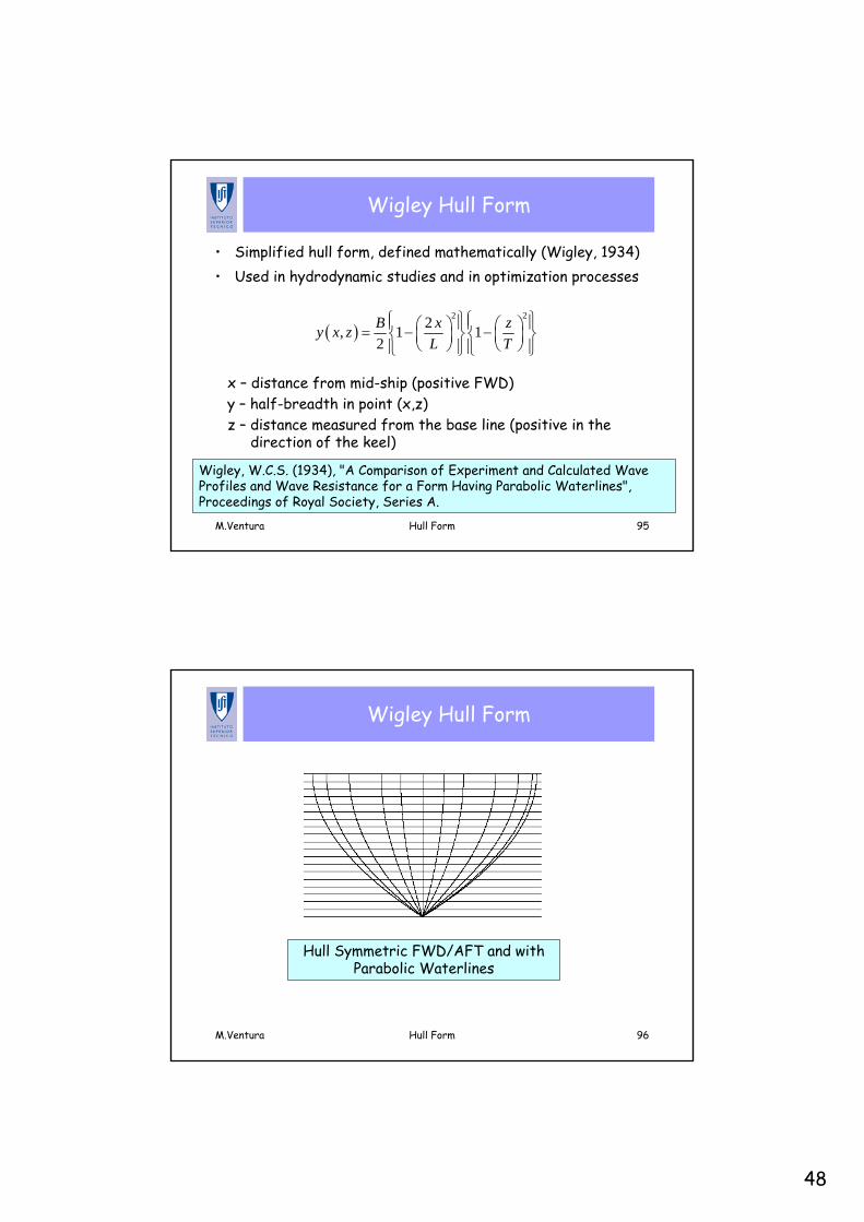
Wigley Hull Form
• Simplified hull form, defined mathematically (Wigley, 1934) • Used in hydrodynamic studies and in optimization processes
( )2 22, 1 1
2B x zy x z
L T⎧ ⎫⎧ ⎫⎪ ⎪⎪ ⎪⎛ ⎞ ⎛ ⎞= − −⎨ ⎬⎨ ⎬⎜ ⎟ ⎜ ⎟
⎝ ⎠ ⎝ ⎠⎪ ⎪⎪ ⎪⎩ ⎭⎩ ⎭
x – distance from mid-ship (positive FWD)y – half-breadth in point (x,z)z – distance measured from the base line (positive in the
direction of the keel)
Wigley, W.C.S. (1934), "A Comparison of Experiment and Calculated WaveProfiles and Wave Resistance for a Form Having Parabolic Waterlines", Proceedings of Royal Society, Series A.
M.Ventura Hull Form 96
Wigley Hull Form
Hull Symmetric FWD/AFT and with Parabolic Waterlines