SD-06_Bottom Ash Handling System_R03
56
B B o o t t t t o o m m A A s s h h H H a a n n d d l l i i n n g g S S y y s s t t e e m m System Description Manual No. SD-06 Revision 003 P.T. CENTRAL JAVA POWER TANJUNG JATI-B (3&4) EXPANSION PROJECT Note z This System Description manual is intended to provide the Tanjung Jati-B 3&4 Power Project operation personnel with the basic information to understand the Bottom Ash Handling System. z No part of this document may be reproduced for use by parties other than Mitsubishi Heavy Industries, Ltd. and P.T. Central Java Power. P.T. CENTRAL JAVA POWER
Transcript of SD-06_Bottom Ash Handling System_R03
BBoottttoomm AAsshh HHaannddlliinngg SSyysstteemm
SSyysstteemm DDeessccrriippttiioonn MMaannuuaall NNoo.. SSDD--0066
RReevviissiioonn 000033
P.T. CENTRAL JAVA POWER TANJUNG JATI-B (3&4) EXPANSION PROJECT
Note This System Description manual is intended to provide the Tanjung Jati-B 3&4 Power Project
operation personnel with the basic information to understand the Bottom Ash Handling System.
No part of this document may be reproduced for use by parties other than Mitsubishi Heavy Industries, Ltd. and P.T. Central Java Power.
PP..TT.. CCEENNTTRRAALL JJAAVVAA PPOOWWEERR
3
Be sure to read this manual.
Contents
1
2
Major Equipment
4
5
6
Flow Path
Technical Data
1
2
3
4
5
6
General
Process Control
Instrumentation Control,Alarm & Trip Setpoints
SystemHandling
Bottom Ash
BBoottttoomm AAsshh HHaannddlliinngg SSyysstteemm i
SD
-.06
R
ev.0
03
-*
Page Number
Description of Revision Revision
Issue Date Date Revised
Pages Inserted
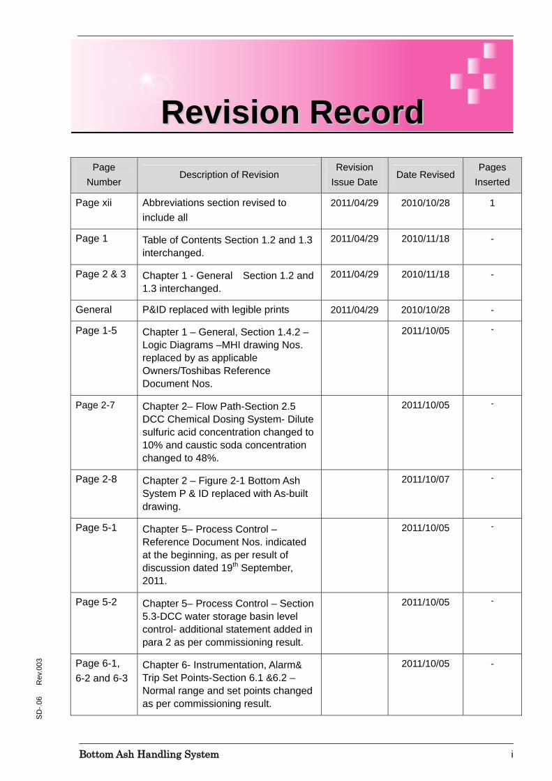
Page xii Abbreviations section revised to include all
2011/04/29 2010/10/28 1
Page 1 Table of Contents Section 1.2 and 1.3 interchanged.
2011/04/29 2010/11/18 -
Page 2 & 3 Chapter 1 - General Section 1.2 and 1.3 interchanged.
2011/04/29 2010/11/18 -
General P&ID replaced with legible prints 2011/04/29 2010/10/28 -
Page 1-5 Chapter 1 – General, Section 1.4.2 – Logic Diagrams –MHI drawing Nos. replaced by as applicable Owners/Toshibas Reference Document Nos.
2011/10/05 -
Page 2-7 Chapter 2– Flow Path-Section 2.5 DCC Chemical Dosing System- Dilute sulfuric acid concentration changed to 10% and caustic soda concentration changed to 48%.
2011/10/05 -
Page 2-8 Chapter 2 – Figure 2-1 Bottom Ash System P & ID replaced with As-built drawing.
2011/10/07 -
Page 5-1 Chapter 5– Process Control – Reference Document Nos. indicated at the beginning, as per result of discussion dated 19th September, 2011.
2011/10/05 -
Page 5-2 Chapter 5– Process Control – Section 5.3-DCC water storage basin level control- additional statement added in para 2 as per commissioning result.
2011/10/05 -
Page 6-1, 6-2 and 6-3
Chapter 6- Instrumentation, Alarm& Trip Set Points-Section 6.1 &6.2 – Normal range and set points changed as per commissioning result.
2011/10/05 -
RReevviissiioonn RReeccoorrdd

BBoottttoomm AAsshh HHaannddlliinngg SSyysstteemm ii
SD
-.06
R
ev.0
03
Purpose of the Plant Usage
This plant is designed to generate electric power of 660MW by the steam turbine generator.
The plant is only used for electric power generation purpose that supports stable and reliable electric power supply to the power grid and supplying steam for auxiliary equipment in the power station.
General
1. To satisfy the purpose mentioned above the following points must be strictly observed,
a) The operation, maintenance and inspection of Equipment must be performed by the persons who have basic technical knowledge and have been trained concerning the hazard of the Equipment and the avoidance of the hazard.
b) The operators and maintainers must read and understand these manuals before starting the operation, maintenance or inspection.
It is often experienced that serious damages to the equipment or personnel have occurred by the unexpected action of operators or maintainers who do not fully understand the equipment.
c) The modification or change of operational specification must be performed under MHI supervision or as per the written acceptances of MHI.
The modification or change of specification causes not only a decline in performance but also a decline in safety for operation of the equipment.
The Customer is requested to contact MHI regarding any modification or changes before the work commences.
The address for MHI to be contacted is shown in this chapter.
2. The operation and maintenance must be performed according to the applicable laws and regulations at the location of the power station.
3. Disposal from the power station must be treated to satisfy the local regulations.
4. The copyright of software, drawings and other documents provided by MHI at all times, is still reserved by MHI.
IImmppoorrttaanntt IInnffoorrmmaattiioonn

BBoottttoomm AAsshh HHaannddlliinngg SSyysstteemm iii
SD
-.06
R
ev.0
03
5. Use or copying of the whole or part of any information provided by MHI for any purpose other than operation and maintenance of this plant without written consent is strictly prohibited.
Important General Notice for Safety
1. The operator and maintainer must have knowledge about the equipment to maintain good operating condition and to avoid danger when using the equipment and systems.
2. The protection measures must satisfy all of the operational functions.
3. The safety activity must be planned systematically as a “Safety and Health management system” and operate continuously.
Safety and Health management system must include the following points,
a) Instruction for use and the maintenance of the personal protective equipment available to operators and maintainers
b) The establishment of a work management organization to make clear the operation directives and work procedures
c) Implementation of training for operator and maintainer
4. The Customer must train the operators and maintainers to act positively and to prevent the occurrence of an accident by using their knowledge of the power plant.
5. The Customer must make the operators and maintainers understand that the most important purpose of safety control is to protect all personnel from accidents and also to maintain operation of the plant without troubles.
6. To prevent accidents involving personnel and equipment, it is necessary to observe the notices of this manual and to keep the correct operation according to the description provided in this manual.
If the notices are not observed, the following dangers could occur to the operator, and to the maintainer.
a) Risk of a fatal accident
b) Danger to lose his health and fitness
c) Danger of damage to the equipment
7. MHI can not forecast all possible dangers existing in the plant such as danger due to human error and/or dangers caused by operating environment.
As this manual and the alert label cannot cover all of the dangers, the operators and maintainers have to pay their full attention to all general safety notices.
BBoottttoomm AAsshh HHaannddlliinngg SSyysstteemm iv
SD
-.06
R
ev.0
03
8. MHI can not be responsible for damages and injury caused by neglecting the notices in this manual, and other necessary general notices.
Instruction of this Manual
1. This manual is provided for people familiar with the use of English. If some person not familiar with English is going to operate the plant, the Customer must then train him specially.
2. The warning labels must be expressed in the English.
3. This manual contains optional matters.
4. Some figures in this manual include internal parts of the equipment which may not be obvious, when looking at the completed equipment drawing.
5. MHI may change the content of this manual without notice.
6. This manual is intended for the use by the operators and maintainers and it must be accessible to them at all times.
7. If the Customer needs more detailed information, please contact MHI local office or MHI’s official agent.
BBoottttoomm AAsshh HHaannddlliinngg SSyysstteemm v
SD
-.06
R
ev.0
03
• The provisions set forth in this section are in addition to all liability and warranty disclaimers and limitations set forth in the Contract, whether arising under law or from course of performance, course of dealing, or usage of trade
• Nothing in these provisions shall constitute or be deemed to constitute any additional liability undertaking or warranty, express or implied, with respect to the Plant. All capitalized terms used, but not defined in this Warranty Limitations section shall have the respective meanings ascribed to them in the Contract.
• The Contract Warranties are subject to the construction, installation and Commissioning works having been performed in full compliance with the requirements stated in (a) the Contract, (b) all manuals provided by MHI, including this manual, (c) all applicable rules, regulations and laws prevailing in the location where the Plant has been installed and will operate, and (d) any other instructions, if any, provided by MHI (collectively, “Rules and Requirements”). The Contract Warranties will NOT cover any accidents, partial or total failure of the Plant, losses or damages to personnel or property (including, without limitation, the Plant’s components, parts, systems and other equipment), or any other liability (collectively, “Accidents and Damages”) in the case of any breach of the stated Rules and Requirements.
• For the detailed terms and conditions of the warranty concerning the Works and Project, refer to the Contract.
WWaarrrraannttyy

BBoottttoomm AAsshh HHaannddlliinngg SSyysstteemm vi
SD
-.06
R
ev.0
03
In addition to the foregoing, the Contract Warranties will NOT cover any of the following Accidents and Damages:
• Accidents and Damages caused by any deviation from the Rules and Requirements;
• Accidents and Damages caused by the modification or re-installation of the Plant after the original installation, or caused by operation of the Plant for a purpose other than that for which it is designed;
• Accidents and Damages caused by natural disasters or accidents during transfer or related handling;
• Accidents and Damages occurring after the term of the warranty has expired;
• Accidents and Damages due to faulty operation or operation not in accordance with the Rules and Requirements;
• Accidents and Damages due to inappropriate maintenance or servicing performed by the Customer, its personnel or any other party.
• Accidents and Damages caused by any components, parts, systems or other equipment other than those delivered by MHI;
• Accidents and Damages caused by unidentifiable reasons including loss of the damaged parts which is necessary to pinpoint a cause of the failure;
• Accidents and Damages caused by referring to inadequate, or incorrect references, data or information provided by the Customer;
• Accidents and Damages or rust/corrosion due to inadequate handling and/or storage by the Customer; or
• Accidents and Damages due to handling, storage and/ or use of the Plant under severe conditions or in an environment that does not meet the design specification conditions.
BBoottttoomm AAsshh HHaannddlliinngg SSyysstteemm vii
SD
-.06
R
ev.0
03
General
• Nothing in this Limitation of Liability section or manual shall constitute or be deemed to constitute any additional liability undertaking or warranty, express or implied, with respect to the Plant. All capitalized terms used, but not defined in this Limitation of Liability section shall have the respective meanings ascribed to them in the Contract.
• The contents of this manual are subject to change without prior notice and without any obligation or liability to MHI.
Use and Disposal
• Use of the Plant must be limited to the use specified by MHI, including without limitation, use of the Plant in accordance with the Contract, this manual, all Safety Manuals, all applicable laws and regulations, and any other instructions, if any, provided by MHI. The Plant components, parts, systems and other equipment (collectively, “Equipment”) must be appropriately disposed of in accordance with the Contract, this manual, all Safety Manuals, all applicable laws and regulations, and any other instructions, if any, provided by MHI.
For Documents and Safety Training
• The Customer’s personnel must read, understand and abide by all documents provided by MHI, including without limitation, the operation and maintenance manuals, safety manuals, and instruction manuals (collectively, “Safety Manuals”) and must have received all required and/or necessary safety training prior to the start of their work. Persons who have not received such safety training are not permitted to work on the installed Plant. This initial training, however, is merely the minimum requirements prior to allowing any personnel to work on the installed Plant. The Customer must, on a continual and regular schedule, give up-to-date training to its personnel on safety requirements, provide testing or other methods to confirm their understanding of the safety training, and confirm that they have the physical and mental capability to perform their respective roles. The Customer’s obligation for safety training and personnel supervision is an ongoing obligation and must be continuously performed and kept current throughout the operation of the Plant. Accidents, partial or total failure of the Plant, damage to personnel or property, loss, injuries, and other liability (collectively, “Liability”) caused by inadequate safety training or the Customer’s personnel’s failure to abide by the documents provided by MHI are expressly excluded from the coverage of any warranty provided by MHI and are the sole and exclusive responsibility of the Customer.
LLiimmiittaattiioonn ooff LLiiaabbiilliittyy
BBoottttoomm AAsshh HHaannddlliinngg SSyysstteemm viii
SD
-.06
R
ev.0
03
• MHI will NOT be liable for any Liability caused by modification or changes made in Plant-related documents (including any Safety Manual) by anyone other than MHI.
For Damage to the Plant
• Accidents may occur by use of Equipment that is acquired from anyone other than MHI or anyone not appointed by MHI to modify or repair this Plant. The Customer shall not be permitted to modify or repair the Plant or change Equipment of the Plant without MHI’s prior written approval, under any circumstance.
• MHI will NOT be liable for any Liability resulting from any abuse, misuse, misapplication of the Equipment supplied by MHI.
• MHI will NOT be liable for any Liability caused by an act by the Customer in violation of the Contract, this manual, any applicable law or regulation, or any Safety Manual or any other instruction provided by MHI, including without limitation, a change of the installation environment or the removal and installation of any Equipment in a location different to that originally selected by MHI.
• MHI will NOT be liable for any Liability caused by a defect, imperfection, or fault, in material or Equipment that was used during a repair, even when such a repair was performed by or under an instruction given by MHI.
BBoottttoomm AAsshh HHaannddlliinngg SSyysstteemm ix
SD
-.06
R
ev.0
03
COPYRIGHT © 2009, MITSUBISHI HEAVY INDUSTRIES, LTD. ALL RIGHTS RESERVED. ANY REPRODUCTION IS EXPRESSLY PROHIBITED.
• All of the content contained in this manual is protected by Japanese,
International and/or United States copyright laws.
• All copyright, trade secrets, and other proprietary and intellectual property rights in the documents provided by Mitsubishi Heavy Industries, Ltd.(“MHI”) (including safety-and-instruction manuals) are at all times owned and reserved by MHI. Subject to your compliance with the restrictions set forth below, MHI grants to you a limited, non-exclusive license in the copyright for the sole purpose of allowing you to use, operate, maintain and inspect the Plant.
• Use, copying, other reproduction of the whole or part of the documents provided by MHI (including safety-and-instruction manuals) for any purpose other than the purpose described above without MHI’s prior written consent is strictly prohibited.
• The act of rewriting, translating, modifying, revising, creating electronic copies, uploading, selling, sublicensing, or otherwise disclosing the whole or part of the manuals is strictly prohibited.
• Except as specifically set forth above, no right, title or license to the documents provided by MHI, whether arising from contract, implication, estoppel or otherwise, is being granted or otherwise transferred.
CCooppyyrriigghhtt
BBoottttoomm AAsshh HHaannddlliinngg SSyysstteemm x
SD
-.06
R
ev.0
03
This Manual was prepared for all personnel who will participate in the operation and maintenance of the plant, and other related mechanical plant and equipment installed.
In this Manual, MHI classifies personnel into the following two classes based on their ability, experience and their attitude to the safety of personnel, and the plant installed.
Only the personnel recognized by the Customer as trained personnel are allowed to perform the operation and maintenance specified in the manuals.
Maintainers and Operators are required to have read and understood the contents of the safety, operation, and maintenance manuals and sufficiently understand the work procedures before actually starting their tasks.
Operators following the instructions of their supervisor or the Shift Charge Engineer are permitted to handle materials to be used in the operation of the plant.
Operators are allowed to turn on the power supply, startup equipment, open up or remove covers or panels on receipt of an instruction or authorization from their superior.
Operators are permitted access to the emergency stop devices following instructions given by their superior when dangerous or hazardous situations are recognized.
Maintainers are permitted to perform maintenance on the plant. They will also perform troubleshooting routine and periodical inspections of the installed equipment. The maintainer will also work under the supervision of MHI’s supervisors during on-the-job training and annual maintenance and overhaul work if MHI’s supervisors are requested to witness periodical inspections, etc.
Maintainers MUST have attended the training programme initially provided by MHI and subsequently by the Customer, and they must have obtained the necessary knowledge and maintenance skills to understand the characteristics of their tasks before actually starting their work.
PPeerrssoonnnneell ttoo wwhhoomm tthhee MMaannuuaall iiss ddiirreecctteedd
Operator
Maintainer
BBoottttoomm AAsshh HHaannddlliinngg SSyysstteemm xi
SD
-.06
R
ev.0
03
For any question or any clarification required, please do not hesitate to contact MHI through the following address(es).
For Support before Operation:
MITSUBISHI HEAVY INDUSTRIES, Ltd.
Nagasaki Shipyard & Machinery Works
1-1, Akunoura Machi, Nagasaki 850-063
CCoonnttaacctt AAddddrreessss

BBoottttoomm AAsshh HHaannddlliinngg SSyysstteemm xii
SD
-.06
R
ev.0
03
Abb. Expanded Form Abb. Expanded Form
1RY Primary ECR Economical Continuous Rating
2RY Secondary ESP Electrostatic Precipitator
3RY Tertiary FD Forced Draft
AC Alternating Current FDF Forced Draft Fan
AUX Auxiliary FCB Fast Cut back
BCP Boiler Water Circulation Pump FGD Flue Gas Desulphurization
BFP Boiler Feed Pump FO Fuel Oil
BFPT Boiler Feed Pump Turbine Gen. Generator
BOP Balance Of Plant H2 Hydrogen
BMCR Boiler Maximum Continuous Rating HDR Header
BMS Burner Management System HP High Pressure
BP Break point HRH Hot Reheat
BSQ Boiler Sequence I&C Instrument and Control
CAC Common Auxiliary Control System IDF Induced Draft Fan
CES Common Electrical Control System IP Intermediate Pressure
CCR Central Control Room LFO Light Fuel Oil
CCCW Closed Cycle Cooling Water LP Low Pressure
CRH Cold Reheat MAX Maximum
CV Control Valve M-BFP Motor Driven Boiler Feed Pump
CW Cooling Water MFT Master Fuel Trip
DCC Drag Chain Conveyor MIN Minimum
DCS Distributed Control System MS Main Steam
DEHC Digital Electro Hydraulic Control MSDS Material Safety Data Sheet
DESH Desuperheater MT Main Turbine
ECO Economizer MV Motor Valve
ECP Electro Chlorination Plant MW Mega Watt
AAbbbbrreevviiaattiioonnss
BBoottttoomm AAsshh HHaannddlliinngg SSyysstteemm xiii
SD
-.06
R
ev.0
03
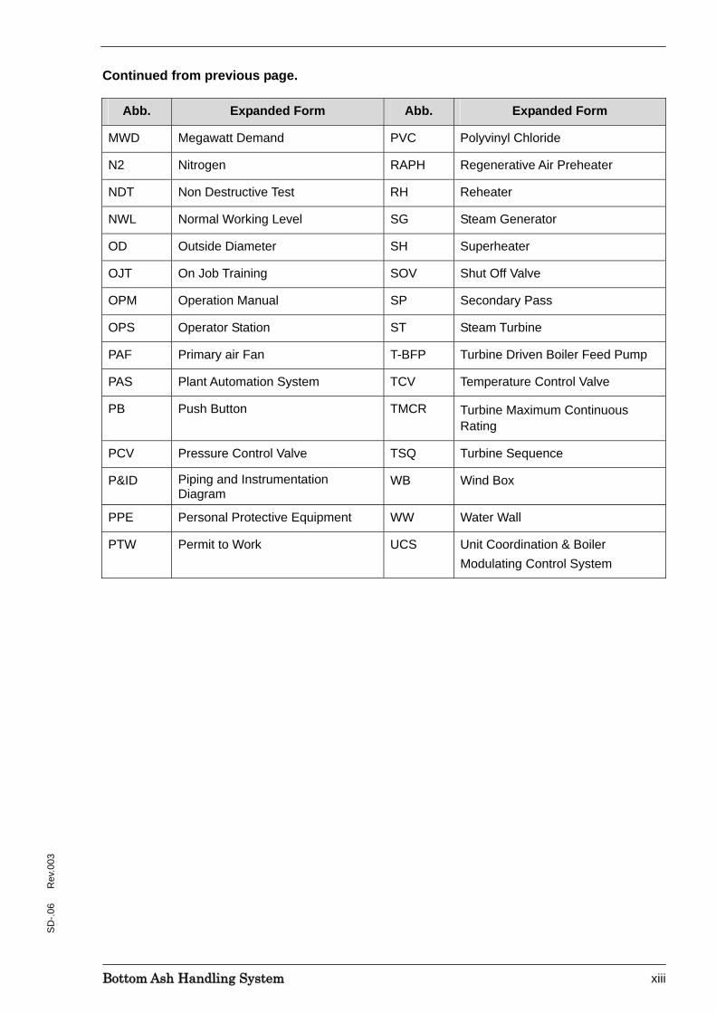
Continued from previous page.
Abb. Expanded Form Abb. Expanded Form
MWD Megawatt Demand PVC Polyvinyl Chloride
N2 Nitrogen RAPH Regenerative Air Preheater
NDT Non Destructive Test RH Reheater
NWL Normal Working Level SG Steam Generator
OD Outside Diameter SH Superheater
OJT On Job Training SOV Shut Off Valve
OPM Operation Manual SP Secondary Pass
OPS Operator Station ST Steam Turbine
PAF Primary air Fan T-BFP Turbine Driven Boiler Feed Pump
PAS Plant Automation System TCV Temperature Control Valve
PB Push Button TMCR Turbine Maximum Continuous Rating
PCV Pressure Control Valve TSQ Turbine Sequence
P&ID Piping and Instrumentation Diagram
WB Wind Box
PPE Personal Protective Equipment WW Water Wall
PTW Permit to Work UCS Unit Coordination & Boiler Modulating Control System

BBoottttoomm AAsshh HHaannddlliinngg SSyysstteemm xiv
SD
-.06
R
ev.0
03
This manual is arranged as follows.
Chapter 1
Chapter 2
Chapter 3
Chapter 4
Chapter 5
Chapter 6
AArrrraannggeemmeenntt ooff tthhee SSyysstteemm DDeessccrriippttiioonn MMaannuuaall
Contents
BBoottttoomm AAsshh HHaannddlliinngg SSyysstteemm 1
SD
-06
Rev
.003
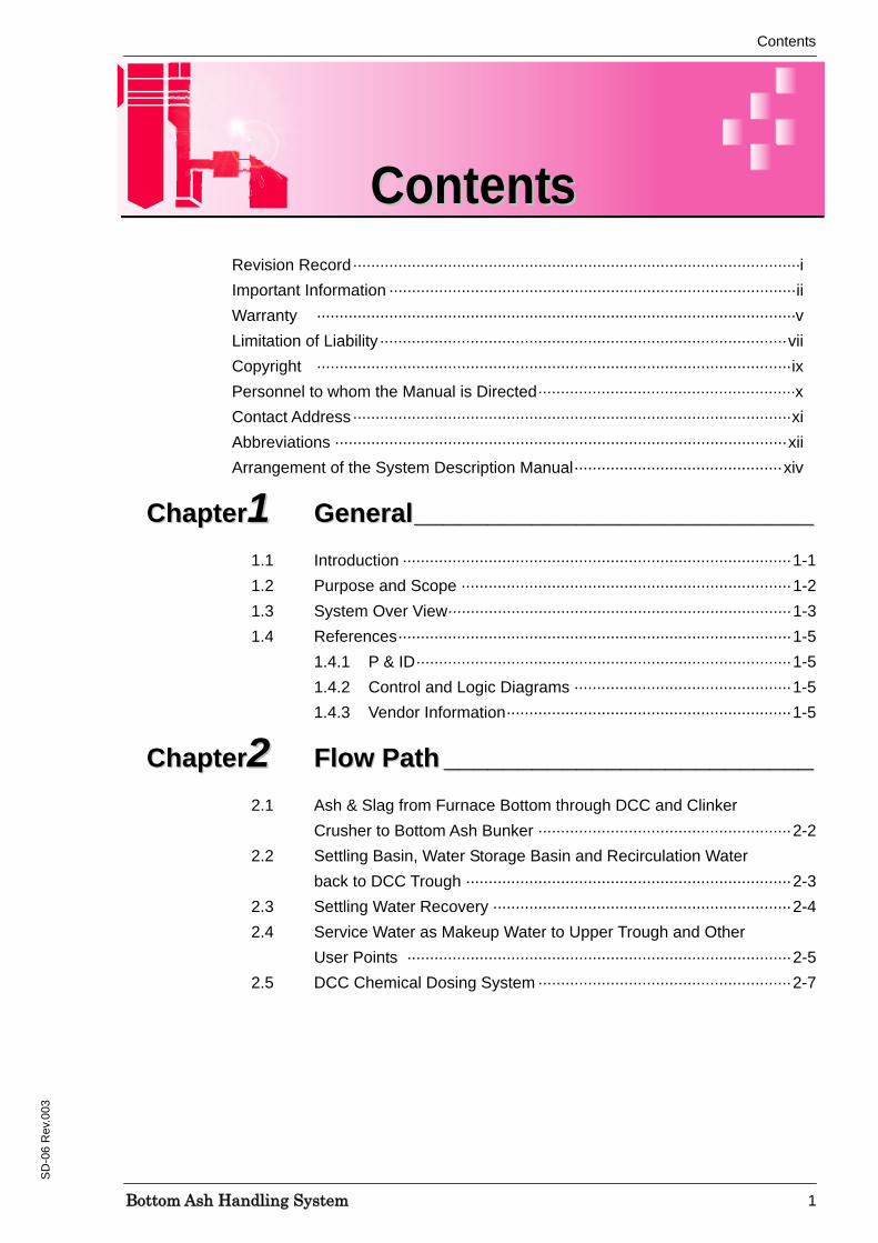
Revision Record···································································································i Important Information ··························································································ii Warranty ··········································································································v Limitation of Liability··························································································vii Copyright ·········································································································ix Personnel to whom the Manual is Directed·························································x Contact Address·································································································xi Abbreviations ····································································································xii Arrangement of the System Description Manual·············································· xiv
CChhaapptteerr11 GGeenneerraall______________________________________________________ 1.1 Introduction ······················································································ 1-1 1.2 Purpose and Scope ········································································· 1-2 1.3 System Over View············································································ 1-3 1.4 References······················································································· 1-5
1.4.1 P & ID···················································································1-5 1.4.2 Control and Logic Diagrams ················································1-5 1.4.3 Vendor Information·······························································1-5
CChhaapptteerr22 FFllooww PPaatthh __________________________________________________ 2.1 Ash & Slag from Furnace Bottom through DCC and Clinker Crusher to Bottom Ash Bunker ························································ 2-2 2.2 Settling Basin, Water Storage Basin and Recirculation Water back to DCC Trough ········································································ 2-3 2.3 Settling Water Recovery ·································································· 2-4 2.4 Service Water as Makeup Water to Upper Trough and Other User Points ····················································································· 2-5 2.5 DCC Chemical Dosing System ························································ 2-7
CCoonntteennttss
Contents
BBoottttoomm AAsshh HHaannddlliinngg SSyysstteemm 2
SD
-06
Rev
.003
CChhaapptteerr33 MMaajjoorr EEqquuiippmmeenntt______________________________________ 3.1 Drag Chain Conveyor ······································································ 3-1 3.2 Clinker Crusher ················································································ 3-5 3.3 DCC Cooling Water Recirculation Pump ········································· 3-8 3.4 DCC Sludge Pump········································································· 3-11 3.5 DCC Cooling Water Heat Exchanger············································· 3-14
CChhaapptteerr44 TTeecchhnniiccaall DDaattaa __________________________________________
CChhaapptteerr55 PPrroocceessss CCoonnttrrooll ______________________________________ 5.1 DCC Water Temperature Control ····················································· 5-2 5.2 DCC Water Level Control································································· 5-2 5.3 DCC Water Storage Basin Level Control ········································· 5-2
CChhaapptteerr66 IInnssttrruummeennttaattiioonnss,, AAllaarrmm && TTrriipp SSeett PPooiinnttss ________________________________________________________
6.1 Instrumentation Parameters Monitored at CCR······························· 6-1 6.2 Instrumentation Parameters Monitored at Local ······························ 6-3
Contents
BBoottttoomm AAsshh HHaannddlliinngg SSyysstteemm 3
SD
-06
Rev
.003
LLiisstt OOff FFiigguurreess Figure 2-1 Bottom Ash P & ID ····························································· 2-8
Figure 3-1 DCC General Arrangement 1/2 ·········································· 3-3
Figure 3-2 DCC General Arrangement 2/2 ·········································· 3-4
Figure 3-3 Clinker Crusher Assembly·················································· 3-6
Figure 3-4 Clinker Crusher Arrangement············································· 3-7
Figure 3-5 DCC Cooling Water Recirculation Pump Outline ··············· 3-9
Figure 3-6 DCC Cooling Water Recirculation Pump Sectional Assembly·········································································· 3-10
Figure 3-7 DCC Sludge Pump Sectional Assembly 1/2····················· 3-12
Figure 3-8 DCC Sludge Pump Sectional Assembly 2/2····················· 3-13
Figure 3-9 DCC Cooler Unit General Arrangement ························· 3-15
LLiisstt ooff TTaabblleess Table 4-1 Drag Chain Conveyor························································· 4-1
Table 4-2 Clinker Crusher ·································································· 4-2
Table 4-3 DCC Cooling Water Heat Exchanger ································· 4-2
Table 4-4 DCC Cooling Water Recirculation Pump···························· 4-3
Table 4-5 DCC Sludge Pump····························································· 4-3
Table 4-6 DCC Chemical Dosing System ·········································· 4-4
Table 6-1 Operation Parameters, Alarm & Trip Set Points - CCR······ 6-1
Table 6-2 Operation Parameters, Alarm & Trip Set Points - Local ····· 6-3
Chapter-1 General
BBoottttoomm AAsshh HHaannddlliinngg SSyysstteemm 1-1
SD
-06
Rev
.003
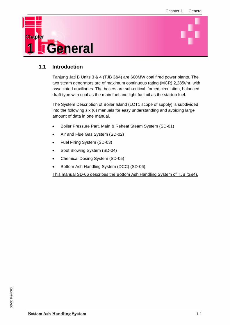
1.1 Introduction
Tanjung Jati B Units 3 & 4 (TJB 3&4) are 660MW coal fired power plants. The two steam generators are of maximum continuous rating (MCR) 2,285t/hr, with associated auxiliaries. The boilers are sub-critical, forced circulation, balanced draft type with coal as the main fuel and light fuel oil as the startup fuel.
The System Description of Boiler Island (LOT1 scope of supply) is subdivided into the following six (6) manuals for easy understanding and avoiding large amount of data in one manual.
• Boiler Pressure Part, Main & Reheat Steam System (SD-01)
• Air and Flue Gas System (SD-02)
• Fuel Firing System (SD-03)
• Soot Blowing System (SD-04)
• Chemical Dosing System (SD-05)
• Bottom Ash Handling System (DCC) (SD-06).
This manual SD-06 describes the Bottom Ash Handling System of TJB (3&4).
CChhaapptteerr
11 GGeenneerraall
Chapter-1 General
BBoottttoomm AAsshh HHaannddlliinngg SSyysstteemm 1-2
SD
-06
Rev
.003
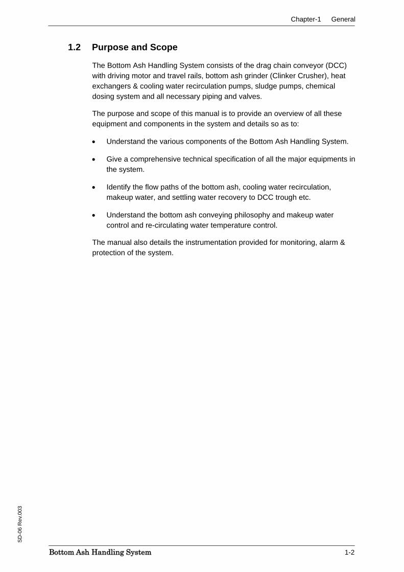
1.2 Purpose and Scope
The Bottom Ash Handling System consists of the drag chain conveyor (DCC) with driving motor and travel rails, bottom ash grinder (Clinker Crusher), heat exchangers & cooling water recirculation pumps, sludge pumps, chemical dosing system and all necessary piping and valves.
The purpose and scope of this manual is to provide an overview of all these equipment and components in the system and details so as to:
• Understand the various components of the Bottom Ash Handling System.
• Give a comprehensive technical specification of all the major equipments in the system.
• Identify the flow paths of the bottom ash, cooling water recirculation, makeup water, and settling water recovery to DCC trough etc.
• Understand the bottom ash conveying philosophy and makeup water control and re-circulating water temperature control.
The manual also details the instrumentation provided for monitoring, alarm & protection of the system.
Chapter-1 General
BBoottttoomm AAsshh HHaannddlliinngg SSyysstteemm 1-3
SD
-06
Rev
.003
1.3 System Over View
The Steam Generator (SG) is fired with coal and is capable to be fired with light fuel oil (LFO) for start-up, low-load, and shutdown purposes. The steam from each SG is passed to its associated steam turbine and, each of the two units can be operated completely independent of each other.
The steam generator is sub-critical, balanced draft, drum-type design, with single reheat and the design live main steam parameters are 174.3barg and 541°C and the reheat steam parameters are 37.5barg and 541°C.
The function of Bottom Ash Handling system is to collect, cool and crush the furnace bottom ash and deliver it to the bottom ash bunker. The bottom ash handling system uses a submerged drag chain conveyor (DCC).
The bottom ash system includes the following major components for each unit:
1. One (1) drag chain conveyor with driving motor and travel rails
2. One (1) bottom ash grinder (Clinker Crusher)
3. Two (2) DCC Cooling Water Recirculation Pump
4. Two (2) DCC Sludge Pump
5. Two (2) DCC Cooling Water Heat Exchanger
6. All necessary piping and valves.
Bottom ash from the steam generator is guided into the water impounded drag chain conveyor upper trough. The submerged drag chain conveyor drags the ash up the inclined section for dewatering before discharging through a discharge chute to a clinker crusher for further grinding and disposal.
The level of water above the submerged drag chain conveyor is automatically controlled to maintain a boiler seal and to protect the conveyor from radiant heat at all times. The capacity of the water trough is sufficient to accommodate at least 8 hours production of ash at 100% MCR with worst coal.
The bottom and the inclined surface are lined with wear plates (30 mm thickness) to extend the life against erosion. The chain return path on the lower dry trough side is lined with abrasion resistant material.
The submerged drag chain conveyor is mounted on rails and equipped with wheels to facilitate rolling it to one side for conveyor and boiler maintenance.
One (1) bottom ash grinder (Clinker Crusher) is provided to grind the maximum amount of bottom ash occurring under all operating conditions and dropped down to the bottom ash bunker. The drive unit of the clinker crusher is an electric motor with reduction gear. The electric motor is designed to permit reverse rotation. Materials used for the clinker crusher is capable of withstanding any abrasion by ash and corrosion by bottom water.
Chapter-1 General
BBoottttoomm AAsshh HHaannddlliinngg SSyysstteemm 1-4
SD
-06
Rev
.003
The makeup water consumption for the Bottom Ash Handling System is minimized by providing a re-circulating cooling water system. The system consists of cooling water heat exchangers, cooling water recirculation pumps and necessary pipelines and valves and utilizes the cooling water from the CCCW System.
A chemical dosing system consisting of dilute sulfuric and caustic soda is provided to maintain the recirculation water quality within limits.
From the clinker crusher, the ash is dropped down to the bottom ash bunker, from where it is disposed to the trucks using wheel loader and carried away periodically.
Chapter-1 General
BBoottttoomm AAsshh HHaannddlliinngg SSyysstteemm 1-5
SD
-06
Rev
.003
1.4 Reference
1.4.1 P&ID
• Bottom Ash P&I Diagram Project Dwg. No.: A-BAD-0-MH-0001 MHI Dwg. No:97000-2165-2-A
1.4.2 Control and Logic Diagrams
• Logic Diagram for Boiler DCC Group (BJ) Owner’s Document No.:A-DCS-I-TS-6425 (Toshiba’s Document No. 3GCH00577)
• Logic Diagrams for UCS-A & UCS-B Owner’s Document No.:A-DCS-I-TS-6468 (Toshiba’s Document No.7M6S2273/2274)
1.4.3 Vendor Information
System/Equipment Vendor General Arrangement of DCC MHI, Nagasaki
DCC Cooling Water Heat Exchanger Dong Hwa Entec
DCC Chemical Dosing System Sakura Seisakusho, Ltd
DCC Cooling Water Recirculation Pump Yokota Manufacturing Co. ,Ltd
DCC Sludge Pumps E.I.M. Electric Co. Ltd
Chapter-2 Flow Path
BBoottttoomm AAsshh HHaannddlliinngg SSyysstteemm 2-1
SD
-06
Rev
.003
The function of Bottom Ash Handling system is to collect, cool and crush the furnace bottom ash and deliver it to the bottom ash bunker. The bottom ash handling system uses a submerged drag chain conveyor (DCC).
The bottom ash system includes the following major components for each unit:
1. One (1) drag chain conveyor with driving motor and travel rails
2. One (1) bottom ash grinder (Clinker Crusher)
3. Two (2) DCC Cooling Water Recirculation Pump
4. Two (2) DCC Sludge Pump
5. Two (2) DCC Cooling Water Heat Exchanger
6. All necessary piping and valves.
Bottom ash from the steam generator is guided into the water impounded drag chain conveyor upper trough. The submerged drag chain conveyor drags the ash up the inclined section for dewatering before discharging through a discharge chute to a clinker crusher for further grinding and disposal.
The level of water above the submerged drag chain conveyor is automatically controlled to maintain a boiler seal and to protect the conveyor from radiant heat at all times. The capacity of the water trough is sufficient to accommodate at least 8 hours production of ash at 100% MCR with worst coal.
The bottom and the inclined surface are lined with wear plates (30 mm thickness) to extend the life against erosion. The chain return path on the lower dry trough side is lined with abrasion resistant material.
The submerged drag chain conveyor is mounted on rails and equipped with wheels to facilitate rolling it to one side for conveyor and boiler maintenance.
One (1) bottom ash grinder (Clinker Crusher) is provided to grind the maximum amount of bottom ash occurring under all operating conditions and dropped down to the bottom ash bunker. The drive unit of the clinker crusher is an electric motor with reduction gear. The electric motor is designed to permit reverse rotation. Materials used for the clinker crusher is capable of withstanding any abrasion by ash and corrosion by bottom water.
The makeup water consumption for the Bottom Ash Handling System is minimized by providing a re-circulating cooling water system. The system consists of cooling water heat exchangers, cooling water recirculation pumps and necessary pipelines and valves and utilizes the cooling water from the CCCW System.
CChhaapptteerr
22 FFllooww PPaatthh
Chapter-2 Flow Path
BBoottttoomm AAsshh HHaannddlliinngg SSyysstteemm 2-2
SD
-06
Rev
.003
A chemical dosing system consisting of dilute sulfuric and caustic soda is provided to maintain the recirculation water quality within limits.
From the clinker crusher, the ash is dropped down to the bottom ash bunker, from where it is disposed to the trucks using wheel loader and carried away periodically.
The flow paths associated with Bottom Ash Handling System are:
• Ash & slag from furnace bottom through DCC and Clinker Crusher to bottom ash bunker.
• Settling basin, water storage basin and recirculation water back to DCC trough.
• Settling Water Recovery
• Makeup Water to DCC Trough
• DCC Chemical Dosing System.
2.1 Ash & Slag from Furnace Bottom through DCC and Clinker Crusher to Bottom Ash Bunker Ash and slag from furnace falls to the water impounded drag chain conveyor upper trough and gets quenched in the water. The submerged drag chain conveyor (DCC) drags the ash up the inclined section for dewatering before discharging through a discharge chute to a clinker crusher for further grinding and disposes to the bottom ash bunker area. The DCC rotating speed is adjustable by inverter control.
The upper trough receives the makeup water, recirculation water and the recovered settling water. An overflow is provided in upper trough and flows to the trench from where it is guided to the settling basin. The upper trough has a drain connection with isolation valve (3BAD-V520). A temperature indicating switch (3AW-TGS501) is provided for high/high-high DCC water temperature annunciation and ON/OFF control of makeup water. The temperature can also be monitored locally.
A level switch (3AW-LS501) is provided in the DCC upper trough for ON/OFF control of makeup water and also annunciation of high and low levels. A level switch (3BAD-LS503) is provided above the clinker crusher spout to alarm the shoot blockage and also trip DCC. The drag chain is continuously washed down on its return path. Gutters are provided at the rear and front side of the bottom trough to direct the water to the trench.
The crusher sealing requirement is provided by service air. The service air pressure can be monitored at local.

Chapter-2 Flow Path
BBoottttoomm AAsshh HHaannddlliinngg SSyysstteemm 2-3
SD
-06
Rev
.003
2.2 Settling Basin, Water Storage Basin and Recirculation Water back to DCC Trough The overflow water from upper trough and the drain water from bottom trough flows through the trench to the settling basin. Dilute sulfuric acid/caustic soda is dosed (refer section 2.5) into the settling basin periodically to maintain the water quality, when the water quality becomes beyond the set values. The settled water is pumped back to upper trough (refer section 2.3), also periodically by sludge pumps. The clear water overflows to the adjacent water storage basin. The water storage basin level is monitored locally at level indicating switch (3BAD-LGS501), which is also used for alarm and pump protection and interlock purposes.
The water from storage basin is re-circulated back to the upper trough by the DCC cooling water recirculation pumps. There are 2 x 100% duty pumps, one in service and the other standby. Each pump takes it suction from storage basin through suction strainers and suction valves (3BAD-V501A/B). The pump discharge is provided with an exhaust valve (3BAD-V516A/B), which vents air/water mixture automatically and is connected back to basin. The pump suction and discharge pressures are monitored locally through the pressure indicators (3BAD-PG501A/B&502A/B).
The pump discharge flows to a common line through discharge check valves (3BAD-V502A/B) and discharge valve (3BAD-V503A/B). A drain connection is provided at the inlet of discharge valve. The pH of the recirculation water is monitored by the analyzer (3BAD-AX501) provided in the common discharge line.
An emergency blow line with blow shutoff valve (3BAD-PN501) is provided to dump water to drain pit, when the water storage level is high-high during operation. The blow off line has an isolation valve (3BAD-V519) at the inlet of shutoff valve.
The recirculation water is tapped from the common discharge line and connected to the DCC upper end of slope for washing down the chain of ash/debris on its return path. This line has a stop valve (3BAD-V513) in common line and isolation valves (3BAD-V514/515) as the line bifurcates to both sides. Another provision by way of tapping of recirculation water is provided to agitate the water storage basin around the suction strainers when necessary.
The recirculation water is cooled in heat exchanger before it is re-circulated to DCC upper trough. The discharge common line from recirculation pump bifurcates and connects to the inlet of 2 x 100% duty heat exchangers (both working normally, and can be isolated for backwashing when necessary). The heat exchangers are provided with inlet and outlet isolation valves (3BAD-V504A/B & 505A/B). Air vent and drains with isolation valves are provided in both heat exchangers. Temperature indicators (3BAD-TG501/502) are provided to monitor the recirculation water temperature at the inlet and outlet of heat exchangers.
Chapter-2 Flow Path
BBoottttoomm AAsshh HHaannddlliinngg SSyysstteemm 2-4
SD
-06
Rev
.003
The heat exchanger outlets join to form a common line and are connected to the DCC upper trough. The recirculation water flow is monitored by the flow transmitter (3BAD-FX501) in DCS. At the DCC upper trough end a stop valve (3BAD-V511) is provided for isolation.
2.3 Settling Water Recovery
As explained earlier, the overflow water from upper trough and the drain water from bottom trough flows through the trench to the settling basin. The settled sludge with water is pumped back periodically to upper trough by the sludge pumps (3BAD-P521A/B).
The pump discharge has check valves (3BAD-V521A/B) and joins to form a single line. A tap off is taken from this line and connected to the agitator nozzles surrounding the sludge pumps through an isolation valve (3BAD-V523). These nozzles mix the settled mud/debris around the pump suction, so that the water carries it to the upper trough.
The common discharge line has an isolation valve (3BAD-V524) and a pressure indicator (3BAD-PG503) is provided to monitor the discharge pressure locally. The common line is routed to the upper trough. A stop valve (3BAD-V525) is provided in this line for isolation, when the line is to be drained off to the drain pit through another isolation valve (3BAD-V526).
Chapter-2 Flow Path
BBoottttoomm AAsshh HHaannddlliinngg SSyysstteemm 2-5
SD
-06
Rev
.003
2.4 Service Water as Makeup Water to Upper Trough and Other User Points Makeup water is supplied to DCC upper trough to replenish the loss of water, as some recirculation water evaporates while quenching the falling hot ash & slag from furnace and any other system loss like seal leakages, gland leakages, water carried away by ash to the bottom ash bunker etc. The makeup water shutoff valve opens/closes to maintain the DCC upper trough level within range.
Service water is used as makeup water and flows to upper trough through a makeup water shutoff valve (3AW-PN501). Isolating valves (3AW-V501/502) are provided at the inlet and outlet of makeup water shutoff valve and a bypass valve (3AW-V503) across the shutoff valve for use during initial fill up/ and or emergency. A drain valve is also provided at the inlet of shutoff valve.
Service water is also tapped for the following purposes:
• Backwashing of the DCC cooling water heat exchangers
• Backwashing of the suction strainers of DCC recirculation pump
• Initial fill up of water storage basin
• Dilution water to DCC caustic soda tank
• Washing down DCC around.
Backwashing of the DCC cooling water heat exchangers
Service water is used for backwashing as and when the heat exchangers are clogged. The service water is connected to the heat exchanger outlet side through isolation valves (3AW-V531A/B). The backwash water from the inlet pipe of the heat exchangers flows to the drain pit through isolation valves (3AW-V533A/B).
Backwashing of the suction strainers of DCC recirculation pump
Service water is used for backwashing the suction strainers and is connected before the suction valves of the DCC cooling water recirculation pump through isolation valves (3AW-V541A/B). The washed water flows to the water storage basin.
Initial fill up of water storage basin
Another tapping of service water from the common line for backwashing suction strainers is used to fill up the water storage basin initially. An isolation valve (3AW-V543) is provided for this purpose in this line.
Chapter-2 Flow Path
BBoottttoomm AAsshh HHaannddlliinngg SSyysstteemm 2-6
SD
-06
Rev
.003
Dilution water to DCC caustic soda tank
A tap off connection of service water from the common line is taken and connected to DCC caustic soda tank through a stop valve (3AW-V525) and isolation valve (3AW-V524). The isolation valve is normally kept closed and used while preparing fresh caustic soda solution.
Another connection from the above common line is provided for settling and storage basin washing. This line also has an isolation valve (3AW-V523).
Washing down DCC around
A separate tapping from the service water line is taken for the supply to DCC around areas for washing, cleaning etc. Three separate tapings are taken for this purpose all around DCC through isolation valves (3AW-V520/521/522).
Chapter-2 Flow Path
BBoottttoomm AAsshh HHaannddlliinngg SSyysstteemm 2-7
SD
-06
Rev
.003
2.5 DCC Chemical Dosing System
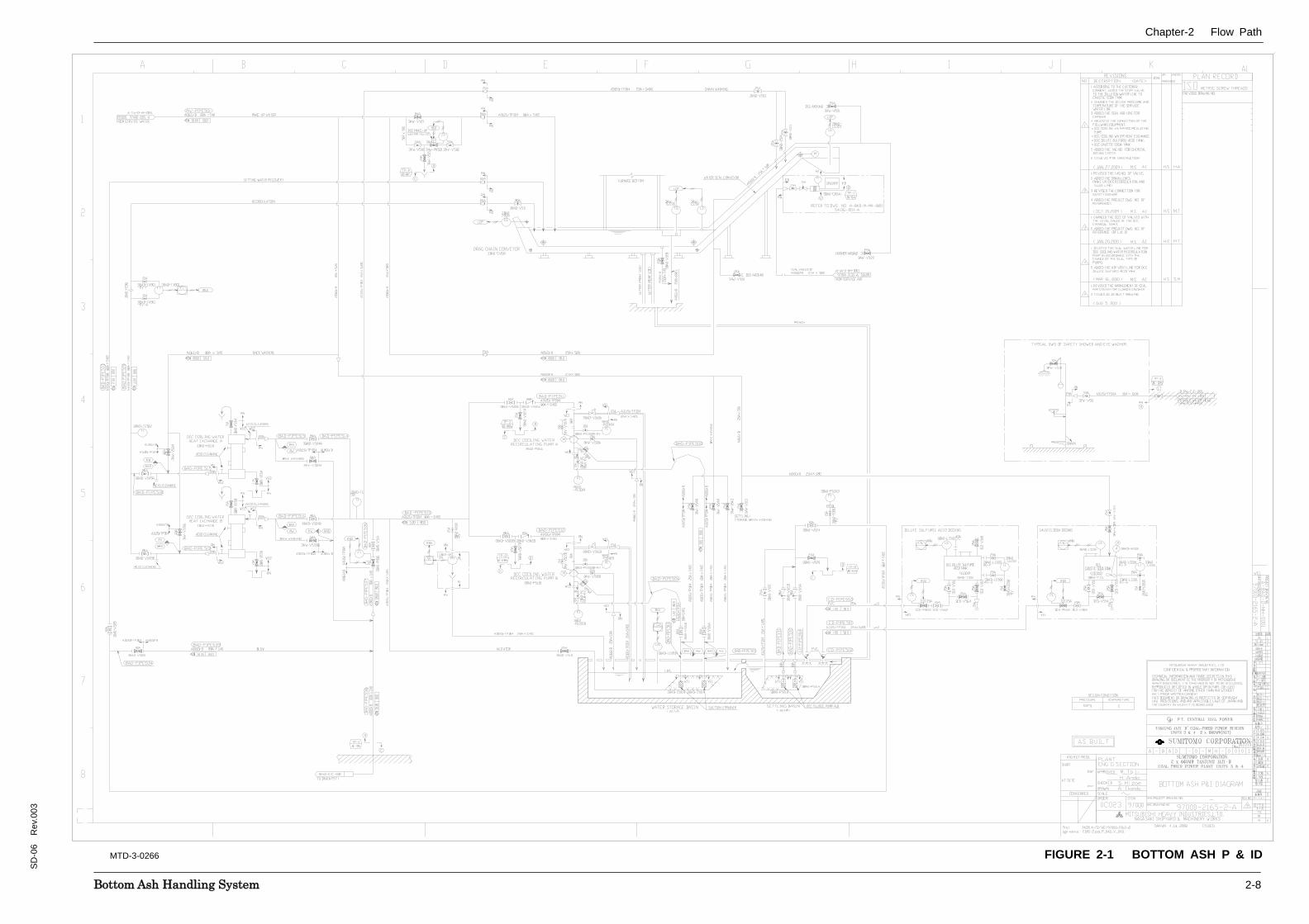
A chemical dosing system is provided to maintain the recirculation water quality within limits. Service water is used as makeup water and for initial filling of water storage basin. However, due to ash/slag falling & quenching process, the water quality gets affected due the property of ash/slag. The pH of the water varies and so it is necessary to maintain the pH with in allowable limits of 5-11. Dilute sulfuric acid is dosed when pH is >9 and dilute caustic soda is dosed when pH is <7. An acid dosing and caustic dosing facility is provided.
Dilute sulfuric acid (10%) is stored in DCC dilute sulfuric tank (3BAD-T532) of 600L capacity. The tank has a local level indicator (3BAD-LG502) and level switch (3BAD-LS502) for low alarm annunciation. Acid fill connection is at top of tank through quick connect coupling and isolation valve (3CD-V568) and tank has an open vent. The tank has a drain connection with isolation valve. The dilute acid flows by gravity to the settling basin through a pipeline connected from tank bottom side through a stop valve (3CD-V561), an isolation valve (3CD-V562) & shutoff valve (3CD-PN 502).
Caustic soda (48%) solution is prepared and stored in DCC caustic soda tank (3BAD-T531) of 1000L capacity. The tank has a local level indicator (3BAD-LG501) and level switch (3BAD-LS501) for low alarm annunciation. Service water for dilution is connected at top of tank through stop and isolating valves. An agitator (3BAD-AG531) is provided for thorough mixing to obtain uniform concentration of caustic soda solution during fresh solution preparation. The tank has a drain connection with isolation valve. The caustic soda solution flows by gravity to the settling basin through a pipeline connected from tank bottom side through a stop valve (3CD-V551), an isolation valve (3CD-V552) & shutoff valve (3CD-PN 501).
Chapter-2 Flow Path
BBoottttoomm AAsshh HHaannddlliinngg SSyysstteemm 2-8
SD
-06
Rev
.003
FIGURE 2-1 BOTTOM ASH P & IDMTD-3-0266
Chapter-3 Major Equipment
BBoottttoomm AAsshh HHaannddlliinngg SSyysstteemm 3-1
SD
-06
Rev
.003
The major equipment associated with Soot Blowing System are the following:
• Drag Chain Conveyor
• Clinker Crusher
• DCC Cooling Water Recirculation Pump
• DCC Sludge Pump
• DCC Cooling Water Heat Exchanger.
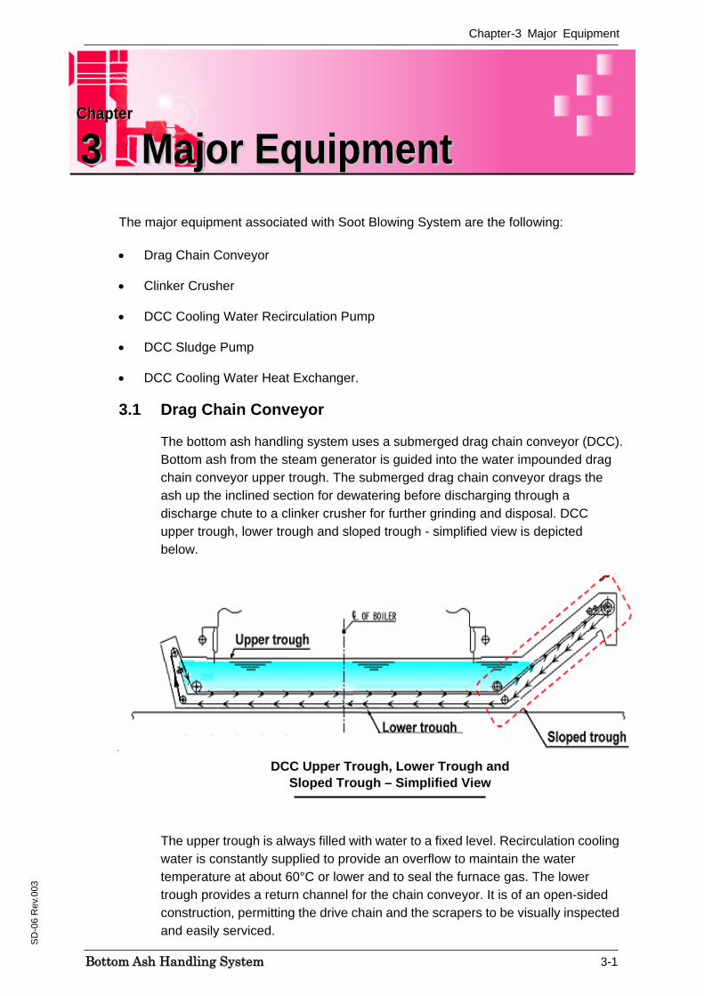
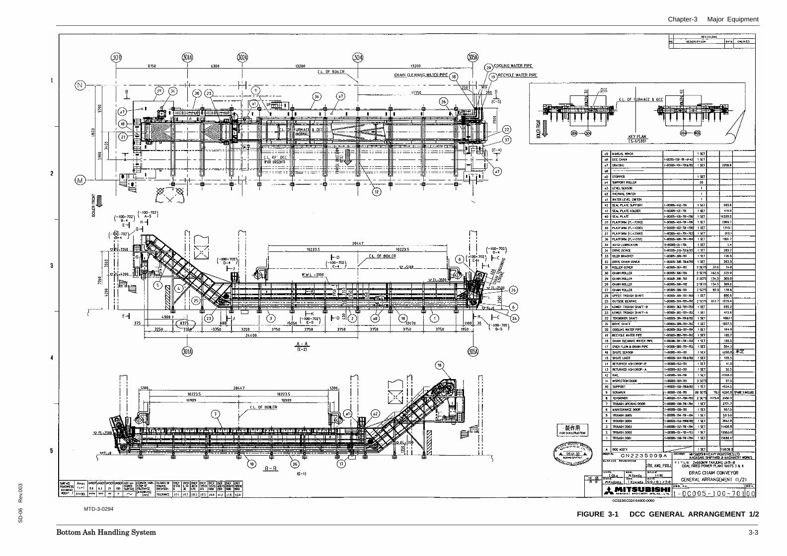
3.1 Drag Chain Conveyor
The bottom ash handling system uses a submerged drag chain conveyor (DCC). Bottom ash from the steam generator is guided into the water impounded drag chain conveyor upper trough. The submerged drag chain conveyor drags the ash up the inclined section for dewatering before discharging through a discharge chute to a clinker crusher for further grinding and disposal. DCC upper trough, lower trough and sloped trough - simplified view is depicted below.
DCC Upper Trough, Lower Trough and Sloped Trough – Simplified View
The upper trough is always filled with water to a fixed level. Recirculation cooling water is constantly supplied to provide an overflow to maintain the water temperature at about 60°C or lower and to seal the furnace gas. The lower trough provides a return channel for the chain conveyor. It is of an open-sided construction, permitting the drive chain and the scrapers to be visually inspected and easily serviced.
CChhaapptteerr
33 MMaajjoorr EEqquuiippmmeenntt
Chapter-3 Major Equipment
BBoottttoomm AAsshh HHaannddlliinngg SSyysstteemm 3-2
SD
-06
Rev
.003
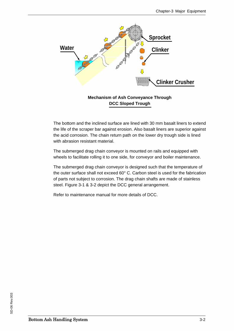
Mechanism of Ash Conveyance Through DCC Sloped Trough
The bottom and the inclined surface are lined with 30 mm basalt liners to extend the life of the scraper bar against erosion. Also basalt liners are superior against the acid corrosion. The chain return path on the lower dry trough side is lined with abrasion resistant material.
The submerged drag chain conveyor is mounted on rails and equipped with wheels to facilitate rolling it to one side, for conveyor and boiler maintenance.
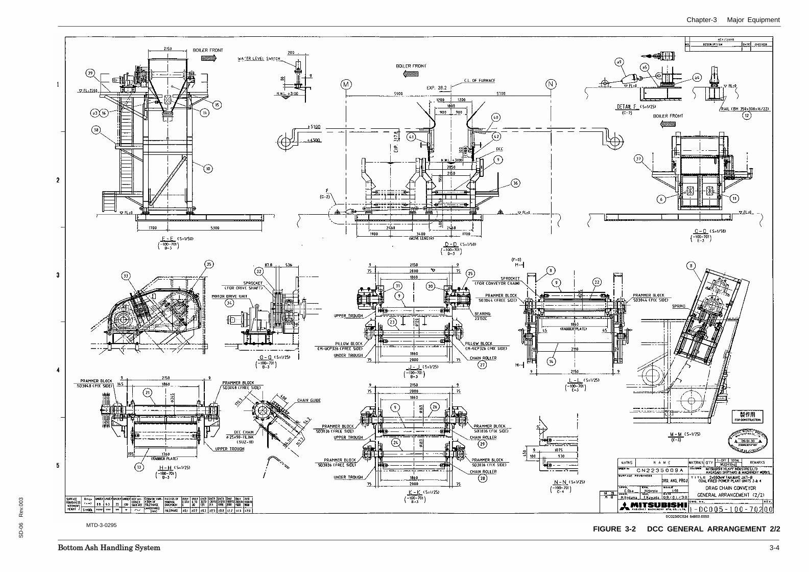
The submerged drag chain conveyor is designed such that the temperature of the outer surface shall not exceed 60° C. Carbon steel is used for the fabrication of parts not subject to corrosion. The drag chain shafts are made of stainless steel. Figure 3-1 & 3-2 depict the DCC general arrangement.
Refer to maintenance manual for more details of DCC.
Clinker
Clinker Crusher
Water
Sprocket
Clinker
Clinker Crusher
Water
Sprocket
Chapter-3 Major Equipment
BBoottttoomm AAsshh HHaannddlliinngg SSyysstteemm 3-3
SD
-06
Rev
.003
FIGURE 3-1 DCC GENERAL ARRANGEMENT 1/2MTD-3-0294
Chapter-3 Major Equipment
BBoottttoomm AAsshh HHaannddlliinngg SSyysstteemm 3-4
SD
-06
Rev
.003
FIGURE 3-2 DCC GENERAL ARRANGEMENT 2/2MTD-3-0295
Chapter-3 Major Equipment
BBoottttoomm AAsshh HHaannddlliinngg SSyysstteemm 3-5
SD
-06
Rev
.003
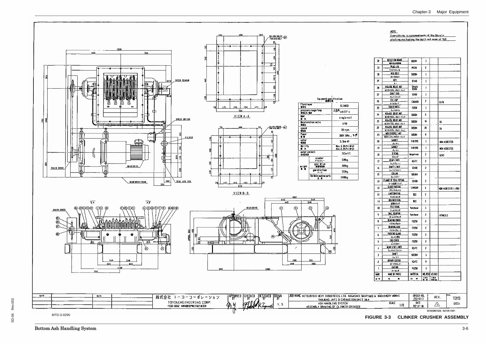
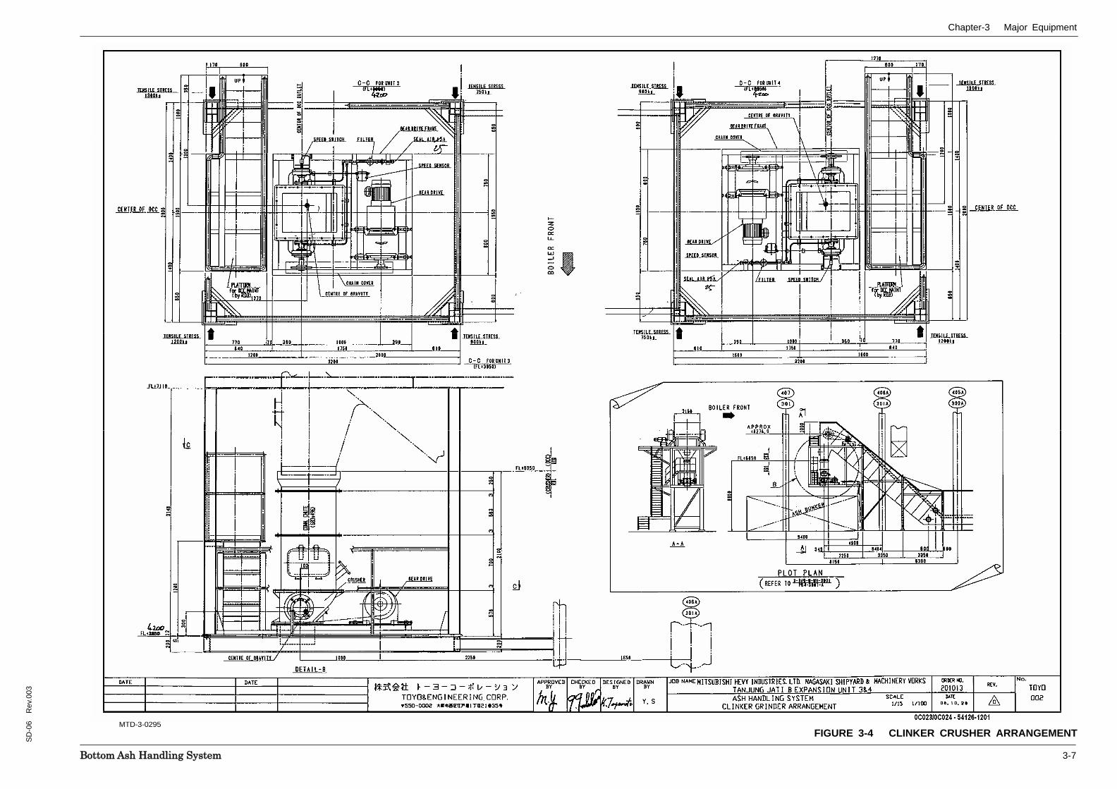
3.2 Clinker Crusher
One (1) bottom ash clinker crusher is supplied. Bottom ash clinker crusher is capable of grinding the maximum amount of bottom ash occurring under all operating conditions to such a particle size as to ensure the smooth flow of slurry to bottom ash bunker. Materials used for the bottom ash grinder is capable of withstanding any abrasion by ash and corrosion by bottom ash water.
The crusher is single roll cutter type. The drive unit of the clinker crusher is an electric geared motor with fluid coupling. The electric motor is designed to permit reverse rotation. Refer section 4 Technical data for the specifications of clinker crusher.
Figures 3-3 & 3-4 depict the clinker crusher assembly and arrangement respectively.
Chapter-3 Major Equipment
BBoottttoomm AAsshh HHaannddlliinngg SSyysstteemm 3-6
SD
-06
Rev
.003
FIGURE 3-3 CLINKER CRUSHER ASSEMBLYMTD-3-0295
Chapter-3 Major Equipment
BBoottttoomm AAsshh HHaannddlliinngg SSyysstteemm 3-7
SD
-06
Rev
.003
FIGURE 3-4 CLINKER CRUSHER ARRANGEMENTMTD-3-0295

Chapter-3 Major Equipment
BBoottttoomm AAsshh HHaannddlliinngg SSyysstteemm 3-8
SD
-06
Rev
.003
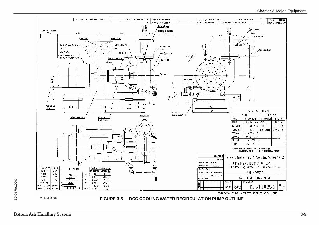
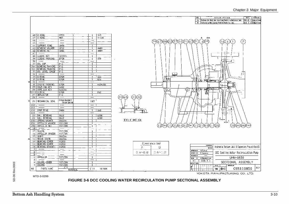
3.3 DCC Cooling Water Recirculation Pump
There are 2 x 100% duty DCC cooling water recirculation pumps provided per DCC, one in service and the other on standby. The pump is a standard centrifugal type, horizontally mounted. It handles DCC water of varying pH “7- 9”. The impeller is semi-open type and thrust & radial bearings are ball bearings.
The rated capacity of the pump is 40m3/h and it develops a differential head of 23m. The drive unit is an electric motor of 5.5kW and coupling used is flexible type.
Figures 3-5 & 3-6 depict the pump outline and sectional assembly respectively.
Chapter-3 Major Equipment
BBoottttoomm AAsshh HHaannddlliinngg SSyysstteemm 3-9
SD
-06
Rev
.000
3
FIGURE 3-5 DCC COOLING WATER RECIRCULATION PUMP OUTLINE MTD-3-0298
Chapter-3 Major Equipment
BBoottttoomm AAsshh HHaannddlliinngg SSyysstteemm 3-10
SD
-06
Rev
.000
3
FIGURE 3-6 DCC COOLING WATER RECIRCULATION PUMP SECTIONAL ASSEMBLY
MTD-3-0299
Chapter-3 Major Equipment
BBoottttoomm AAsshh HHaannddlliinngg SSyysstteemm 3-11
SD
-06
Rev
.003
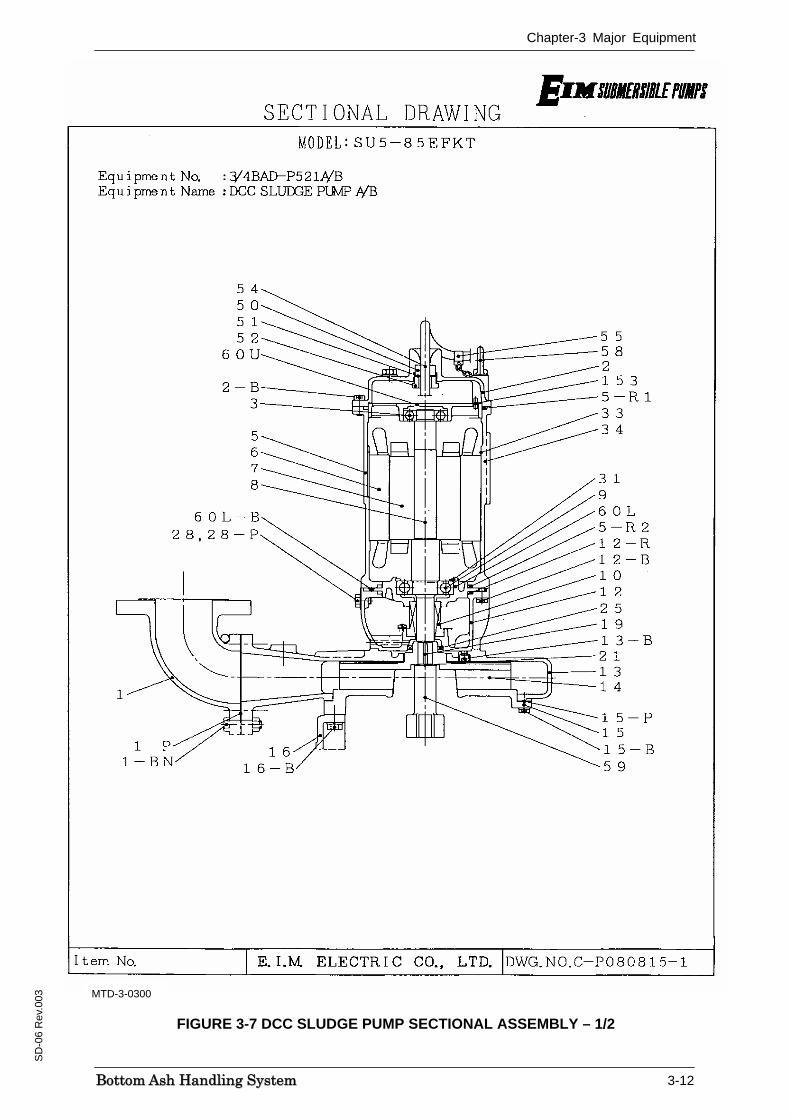
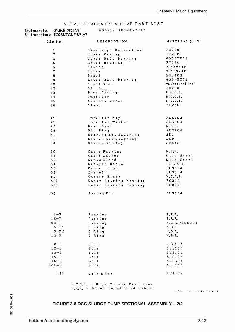
3.4 DCC Sludge Pump
There are 2 x 100% duty DCC sludge pumps provided per DCC, one in service and the other on standby. The pump is a standard submersible type, vertically mounted. It handles DCC sludge water of varying pH “7-9”.
The rated capacity of the pump is 0.5m3/min and it develops a total head of 12m. The drive unit is an electric motor of 3.7kW and motor is designed for submerged water condition.
Figure 3-7 depicts the sludge pump sectional assembly.
Chapter-3 Major Equipment
BBoottttoomm AAsshh HHaannddlliinngg SSyysstteemm 3-12
SD
-06
Rev
.003
FIGURE 3-7 DCC SLUDGE PUMP SECTIONAL ASSEMBLY – 1/2
MTD-3-0300
Chapter-3 Major Equipment
BBoottttoomm AAsshh HHaannddlliinngg SSyysstteemm 3-13
SD
-06
Rev
.003
FIGURE 3-8 DCC SLUDGE PUMP SECTIONAL ASSEMBLY – 2/2
Chapter-3 Major Equipment
BBoottttoomm AAsshh HHaannddlliinngg SSyysstteemm 3-14
SD
-06
Rev
.003
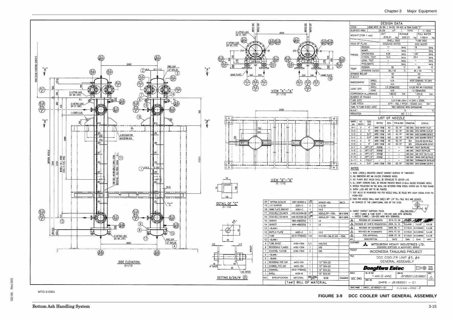
3.5 DCC Cooling Water Heat Exchanger
There are 2 x 100% duty DCC cooling water heat exchangers provided per DCC, both in service normally at 50% duty. However, when any maintenance, or clogging & backwashing of a heat exchanger is necessary, the DCC continues in operation with the available heat exchanger on 100% duty.
The heat exchanger is a standard shell & tube type, vertically mounted. It handles DCC recirculation water on tube side and closed cooling water on shell side. The design specifications are listed in section 4.0 Technical Data.
Figure 3-9 depicts the general assembly of the DCC cooler unit.
Chapter-3 Major Equipment
BBoottttoomm AAsshh HHaannddlliinngg SSyysstteemm 3-15
SD
-06
Rev
.003
FIGURE 3-9 DCC COOLER UNIT GENERAL ASSEMBLYMTD-3-0301
Chapter-4 Technical Data
BBoottttoomm AAsshh HHaannddlliinngg SSyysstteemm 4-1
SD
-06
Rev
.003
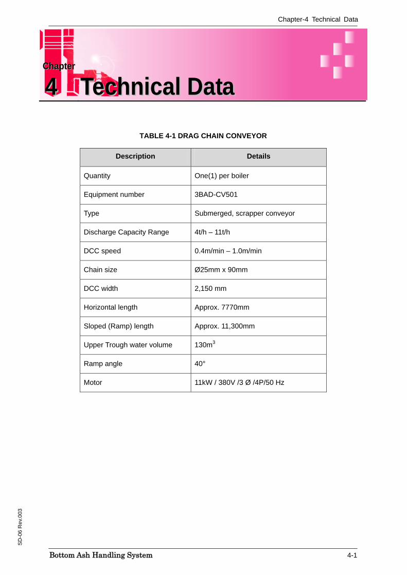
TABLE 4-1 DRAG CHAIN CONVEYOR
Description Details
Quantity One(1) per boiler
Equipment number 3BAD-CV501
Type Submerged, scrapper conveyor
Discharge Capacity Range 4t/h – 11t/h
DCC speed 0.4m/min – 1.0m/min
Chain size Ø25mm x 90mm
DCC width 2,150 mm
Horizontal length Approx. 7770mm
Sloped (Ramp) length Approx. 11,300mm
Upper Trough water volume 130m3
Ramp angle 40°
Motor 11kW / 380V /3 Ø /4P/50 Hz
CChhaapptteerr
44 TTeecchhnniiccaall DDaattaa
Chapter-4 Technical Data
BBoottttoomm AAsshh HHaannddlliinngg SSyysstteemm 4-2
SD
-06
Rev
.003
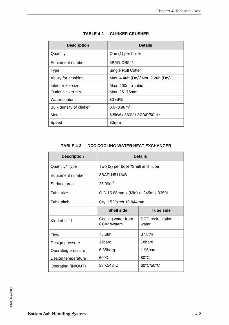
TABLE 4-2 CLINKER CRUSHER
Description Details
Quantity One (1) per boiler
Equipment number 3BAD-CR541
Type Single Roll Cutter
Ability for crushing Max. 4.4t/h (Dry)/ Nor. 2.2t/h (Dry)
Inlet clinker size Outlet clinker size
Max. 200mm cubic Max. 25~75mm
Water content. 30 wt%
Bulk density of clinker 0.6~0.8t/m3
Motor 5.5kW / 380V / 3Ø/4P/50 Hz
Speed 30rpm
TABLE 4-3 DCC COOLING WATER HEAT EXCHANGER
Description Details
Quantity/ Type Two (2) per boiler/Shell and Tube
Equipment number 3BAD-H511A/B
Surface area 25.39m2
Tube size O.D 15.88mm x (Min) t1.245m x 3350L
Tube pitch Qty: 152/pitch 19.844mm
Shell side Tube side
Kind of fluid Cooling water from CCW system
DCC recirculation water
Flow 75.6t/h 37.8t/h
Design pressure 11barg 18barg
Operating pressure 6.35barg 1.96barg
Design temperature 60°C 80°C
Operating (IN/OUT) 38°C/43°C 60°C/50°C

Chapter-4 Technical Data
BBoottttoomm AAsshh HHaannddlliinngg SSyysstteemm 4-3
SD
-06
Rev
.003
TABLE 4-4 DCC COOLING WATER RECIRCULATION PUMP
Description Details
Quantity/Type Two (2) per boiler/ Centrifugal
Equipment number 3BAD-P511A/B
Capacity-rated 40m3/h
Head 23m
Liquid handled DCC water (pH 5.0-11.0)
Motor 5.5kW / 380V / 3 Ø /4P/50 Hz
TABLE 4-5 DCC SLUDGE PUMP
Description Details
Quantity/Type Two (2) per boiler/ Submersible
Equipment number 3BAD-P521A/B
Rated Flow 0.5m3/min
Rated Head 12m
Liquid handled DCC water (pH 5.0-11.0)
Motor 3.7kW / 380V / 3 Ø /4P/50 Hz
Chapter-4 Technical Data
BBoottttoomm AAsshh HHaannddlliinngg SSyysstteemm 4-4
SD
-06
Rev
.003
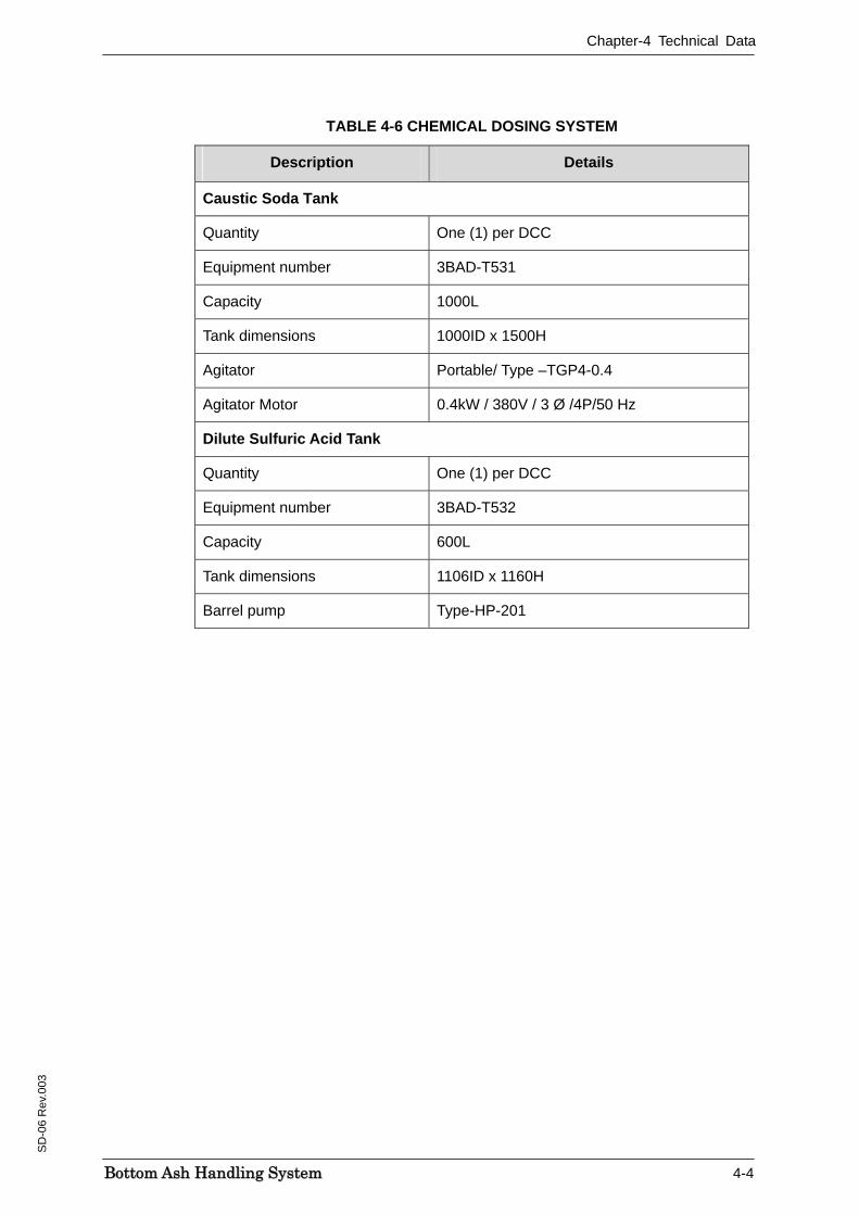
TABLE 4-6 CHEMICAL DOSING SYSTEM
Description Details
Caustic Soda Tank
Quantity One (1) per DCC
Equipment number 3BAD-T531
Capacity 1000L
Tank dimensions 1000ID x 1500H
Agitator Portable/ Type –TGP4-0.4
Agitator Motor 0.4kW / 380V / 3 Ø /4P/50 Hz
Dilute Sulfuric Acid Tank
Quantity One (1) per DCC
Equipment number 3BAD-T532
Capacity 600L
Tank dimensions 1106ID x 1160H
Barrel pump Type-HP-201
Chapter-5 Process Control
BBoottttoomm AAsshh HHaannddlliinngg SSyysstteemm 5-1
SD
-06
Rev
.003
Reference is made to the following documents:
• Logic Diagrams for UCS-A & UCS-B Owner’s Document No.:A-DCS-I-TS-6468 (Toshiba Doc. No.7M6S2273/2274)
(Schematic Diagram of UCS-A & UCS-B:A-DCS-I-TS-5456/5457 (7K6S0 383/384)
DCS is provided for the Tanjung Jati 3&4 Units and basically all operations are carried out from the Central Control Room. The DCS consists of Unit DCS and Common DCS and coordinates with other systems like EHV System etc. for the complete operation of the plant.
Boiler modulating control is implemented by UCS and the functions consist of the following items.
1 Unit coordinate control
2 Combustion control
3 Furnace draft control
4 Feed water control
5 Steam temperature control
6 Primary air flow/pulverizer outlet temperature control
7 Primary air pressure control
8 Auxiliary steam pressure control
9 AH cold end metal temperature control
10 Wind box damper control
11 Burner atomizing steam/air pressure control
12 Pulverizer inerting steam pressure control
13 Boiler blowdown tank level/temperature control
14 Soot blower pressure control
15 Chemical injection control
16 Turbine bypass control.
All the above controls are described in System Description documents SD-01 to SD-05 as applicable to the system.
CChhaapptteerr
55 PPrroocceessss CCoonnttrrooll
Chapter-5 Process Control
BBoottttoomm AAsshh HHaannddlliinngg SSyysstteemm 5-2
SD
-06
Rev
.003
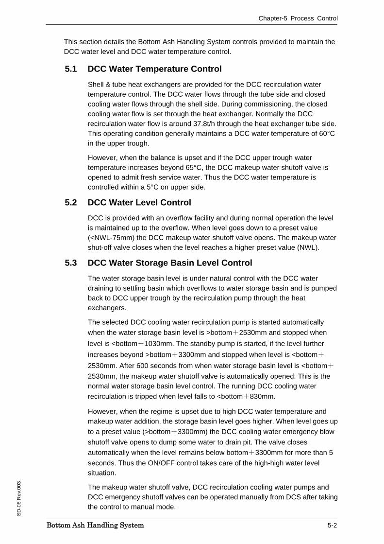
This section details the Bottom Ash Handling System controls provided to maintain the DCC water level and DCC water temperature control.
5.1 DCC Water Temperature Control Shell & tube heat exchangers are provided for the DCC recirculation water temperature control. The DCC water flows through the tube side and closed cooling water flows through the shell side. During commissioning, the closed cooling water flow is set through the heat exchanger. Normally the DCC recirculation water flow is around 37.8t/h through the heat exchanger tube side. This operating condition generally maintains a DCC water temperature of 60°C in the upper trough.
However, when the balance is upset and if the DCC upper trough water temperature increases beyond 65°C, the DCC makeup water shutoff valve is opened to admit fresh service water. Thus the DCC water temperature is controlled within a 5°C on upper side.
5.2 DCC Water Level Control DCC is provided with an overflow facility and during normal operation the level is maintained up to the overflow. When level goes down to a preset value (<NWL-75mm) the DCC makeup water shutoff valve opens. The makeup water shut-off valve closes when the level reaches a higher preset value (NWL).
5.3 DCC Water Storage Basin Level Control The water storage basin level is under natural control with the DCC water draining to settling basin which overflows to water storage basin and is pumped back to DCC upper trough by the recirculation pump through the heat exchangers.
The selected DCC cooling water recirculation pump is started automatically when the water storage basin level is >bottom+2530mm and stopped when level is <bottom+1030mm. The standby pump is started, if the level further increases beyond >bottom+3300mm and stopped when level is <bottom+
2530mm. After 600 seconds from when water storage basin level is <bottom+
2530mm, the makeup water shutoff valve is automatically opened. This is the normal water storage basin level control. The running DCC cooling water recirculation is tripped when level falls to <bottom+830mm.
However, when the regime is upset due to high DCC water temperature and makeup water addition, the storage basin level goes higher. When level goes up to a preset value (>bottom+3300mm) the DCC cooling water emergency blow shutoff valve opens to dump some water to drain pit. The valve closes automatically when the level remains below bottom+3300mm for more than 5 seconds. Thus the ON/OFF control takes care of the high-high water level situation.
The makeup water shutoff valve, DCC recirculation cooling water pumps and DCC emergency shutoff valves can be operated manually from DCS after taking the control to manual mode.

Chapter-6 Instrumentations, Alarm & Trip Set Points
BBoottttoomm AAsshh HHaannddlliinngg SSyysstteemm 6-1
SD
-06
Rev
.003
The instrumentation shown in the TABLE 6-1/6-2 is provided in the Bottom Ash Handling System.
6.1 Instrumentation Parameters Monitored at CCR
TABLE 6-1 OPERATION PARAMETERS, ALARM & TRIP SET POINTS-CCR
Instrument Tag No
Description Normal Range at or near full load
Alarm/Trip Set Point
Function
3BAD-FX501 DCC recirculation water flow 40t/h - Monitoring
3BAD-AX501 DCC recirculation water pH 7-9 <6.5 Caustic soda dosing shutoff valve open permit
<NWL-75 mm Low alarm
DCC Make up water shutoff valve open
NWL DCC Make up water shutoff valve close
<NWL-90 mm DCC trip
3AW-LS501 DCC cooling water level NWL
>NWL+100 mm High alarm
>65ºC DCC Make up water shutoff valve open
3AW-TGS501 DCC cooling water temperature <60ºC
>70ºC High alarm
3BAD-LS503 DCC shoot level >Top-2660mm <Top-2660mm Clinker level high alarm & DCC trip
3BAD-LS502 Dilute sulfuric acid dosing tank level >Bottom +180 mm
< Bottom +180 mm
Low alarm
3BAD-LS501 Dilute caustic soda acid dosing tank level
>Bottom +700 mm
< Bottom +700 mm
Low alarm
CChhaapptteerr
IInnssttrruummeennttaattiioonnss,, AAllaarrmm && 66 TTrriipp SSeett PPooiinnttss
Chapter-6 Instrumentations, Alarm & Trip Set Points
BBoottttoomm AAsshh HHaannddlliinngg SSyysstteemm 6-2
SD
-06
Rev
.003
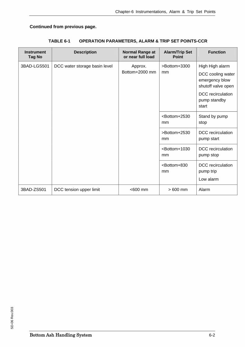
Continued from previous page.
TABLE 6-1 OPERATION PARAMETERS, ALARM & TRIP SET POINTS-CCR
Instrument Tag No
Description Normal Range at or near full load
Alarm/Trip Set Point
Function
>Bottom+3300 mm
High High alarm
DCC cooling water emergency blow shutoff valve open
DCC recirculation pump standby start
<Bottom+2530 mm
Stand by pump stop
>Bottom+2530 mm
DCC recirculation pump start
<Bottom+1030 mm
DCC recirculation pump stop
3BAD-LGS501 DCC water storage basin level Approx. Bottom+2000 mm
<Bottom+830 mm
DCC recirculation pump trip
Low alarm
3BAD-ZS501 DCC tension upper limit <600 mm > 600 mm Alarm
Chapter-6 Instrumentations, Alarm & Trip Set Points
BBoottttoomm AAsshh HHaannddlliinngg SSyysstteemm 6-3
SD
-06
Rev
.003
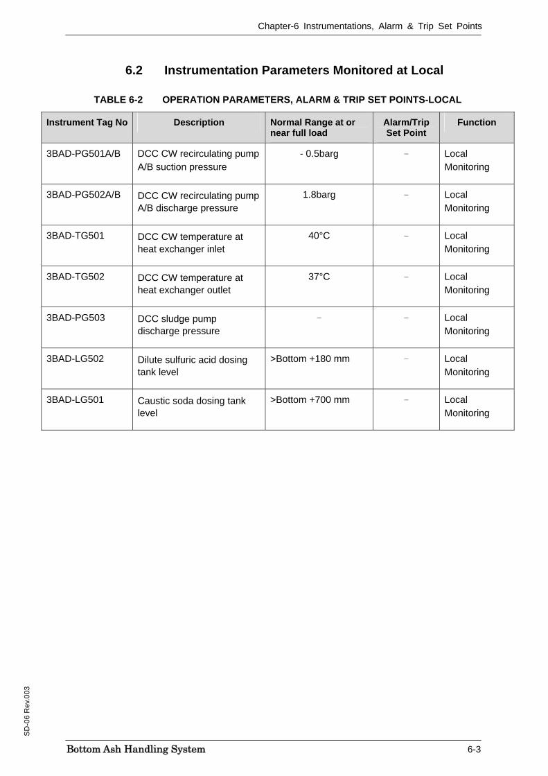
6.2 Instrumentation Parameters Monitored at Local
TABLE 6-2 OPERATION PARAMETERS, ALARM & TRIP SET POINTS-LOCAL
Instrument Tag No Description Normal Range at or near full load
Alarm/Trip Set Point
Function
3BAD-PG501A/B DCC CW recirculating pump A/B suction pressure
- 0.5barg - Local Monitoring
3BAD-PG502A/B DCC CW recirculating pump A/B discharge pressure
1.8barg - Local Monitoring
3BAD-TG501 DCC CW temperature at heat exchanger inlet
40°C - Local Monitoring
3BAD-TG502 DCC CW temperature at heat exchanger outlet
37°C - Local Monitoring
3BAD-PG503 DCC sludge pump discharge pressure
- - Local Monitoring
3BAD-LG502 Dilute sulfuric acid dosing tank level
>Bottom +180 mm - Local Monitoring
3BAD-LG501 Caustic soda dosing tank level
>Bottom +700 mm - Local Monitoring