Scrambling Code for WCDMA_motorola
20
In a Wideband Code Division Multiple Access (WCDMA) environment, each user is assigned a unique complex scrambling sequence to encode its information-bearing signal. The receiver has the scrambling code of the user, unscrambles the received signal, and recovers the original data [1]. This application note presents a method for complex pseudo-random sequence (PN code) generation and complex scrambling of an I/Q code multiplexed signal on a StarCore ® SC140 digital signal processor (DSP). The PN codes in this application note are generated for a WCDMA Universal Mobile Telecommunications Systems (UMTS) uplink (signal from handset to base station) according to the third-generation partnership project (3GPP) specifications. This application note provides practical information to help users understand PN code generation and complex scrambling, which are required in the WCDMA standards. Typically, these operations are performed on Architecture-Specific Integrated Circuits (ASICs), but here we explore the use of the Motorola StarCore SC140 digital signal processing (DSP) core to accomplish the same task. 1 Pseudo-Random Sequences Pseudo-random sequences or PN codes are sequences of 1s and 0s generated by an algorithm so that the resulting numbers look statistically independent and uniformly distributed. A random signal differs from a pseudo-random signal in that a random signal cannot be predicted. A pseudo-random signal is not random at all; it is a deterministic, periodic signal that is known to both the transmitter and the receiver. Even though the signal is deterministic, it appears to have the statistical properties of sampled white noise. To an unauthorized listener, it appears to be a truly random signal. 1.1 Randomness Properties CDMA systems achieve their multiple access capability using large sets of sequences with three basic properties that are applied to a periodic binary sequence as a test for the appearance of randomness [2]: • Balance Property. In each period of the sequence, the number of binary 1s must differ from the number of binary 0s by at most one digit. In other words, the sequences are balanced so that each element of the sequence alphabet occurs with equal frequency. • Run Property. A run is defined as a sequence of the same binary digit. The appearance of a different binary digit marks the start of a new run. The length of the run is the number of digits in the run. For the randomness run property, in each period, about one-half the runs of each binary digit should be of length 1, about one-fourth of length 2, one-eighth of length 3, and so on. • Correlation Property. Random sequences are often described in terms of their correlation properties. A scrambling sequence in a CDMA system must have small off-peak autocorrelation values to allow for rapid sequence acquisition at the receiver and to minimize self interference due to multipath acquisitions. Furthermore, the cross correlations are small enough among such sequences at all delays to minimize multiple-access interference. Application Note AN2254/D Rev. 0, 4/2002 Scrambling Code Generation for WCDMA on the StarCore SC140 Core by Imran Ahmed CONTENTS 1 Pseudo-Random ................ Sequences ....................... 1 1.1 Randomness Properties 1 1.2 Generating Pseudo-Random Sequences ..................... 2 2 Scrambling Codes for WCDMA ......................... 2 2.1 Generating Long Complex Scrambling Codes............................ 3 2.2 Scrambling an I-Q/Code Multiplexed Signal ....... 5 3 Software Implementation on the StarCore SC140 Core .................... 6 3.1 Allocating Memory Space ............................ 6 3.2 Generating Binary PN Code and Forming Complex Scrambling Sequences ..................... 7 3.3 Forming the Complex Scrambling Sequences.. 9 3.4 Complex Scrambling of an IQ/Code Multiplexed Signal ......................... 13 4 Results .......................... 16 5 References .................... 18
-
Upload
subhasish-mahapatra -
Category
Documents
-
view
136 -
download
1
Transcript of Scrambling Code for WCDMA_motorola

Application Note
AN2254/DRev. 0, 4/2002
Scrambling Code Generation for WCDMA on the StarCore SC140 Core
by Imran Ahmed
CONTENTS
1 Pseudo-Random ................Sequences ....................... 1
1.1 Randomness Properties 11.2 Generating
Pseudo-RandomSequences ..................... 2
2 Scrambling Codes for WCDMA ......................... 2
2.1 Generating LongComplex Scrambling Codes............................ 3
2.2 Scrambling an I-Q/CodeMultiplexed Signal ....... 5
3 Software Implementationon the StarCore SC140 Core .................... 6
3.1 Allocating Memory Space ............................ 6
3.2 Generating Binary PNCode and FormingComplex Scrambling Sequences ..................... 7
3.3 Forming the ComplexScrambling Sequences.. 9
3.4 Complex Scrambling of an IQ/Code Multiplexed Signal ......................... 13
4 Results .......................... 165 References .................... 18
In a Wideband Code Division Multiple Access (WCDMA) environment, each user is assigned a unique complex scrambling sequence to encode its information-bearing signal. The receiver has the scrambling code of the user, unscrambles the received signal, and recovers the original data [1]. This application note presents a method for complex pseudo-random sequence (PN code) generation and complex scrambling of an I/Q code multiplexed signal on a StarCore® SC140 digital signal processor (DSP). The PN codes in this application note are generated for a WCDMA Universal Mobile Telecommunications Systems (UMTS) uplink (signal from handset to base station) according to the third-generation partnership project (3GPP) specifications.
This application note provides practical information to help users understand PN code generation and complex scrambling, which are required in the WCDMA standards. Typically, these operations are performed on Architecture-Specific Integrated Circuits (ASICs), but here we explore the use of the Motorola StarCore SC140 digital signal processing (DSP) core to accomplish the same task.
1 Pseudo-Random SequencesPseudo-random sequences or PN codes are sequences of 1s and 0s generated by an algorithm so that the resulting numbers look statistically independent and uniformly distributed. A random signal differs from a pseudo-random signal in that a random signal cannot be predicted. A pseudo-random signal is not random at all; it is a deterministic, periodic signal that is known to both the transmitter and the receiver. Even though the signal is deterministic, it appears to have the statistical properties of sampled white noise. To an unauthorized listener, it appears to be a truly random signal.
1.1 Randomness PropertiesCDMA systems achieve their multiple access capability using large sets of sequences with three basic properties that are applied to a periodic binary sequence as a test for the appearance of randomness [2]:
• Balance Property. In each period of the sequence, the number of binary 1s must differ from the number of binary 0s by at most one digit. In other words, the sequences are balanced so that each element of the sequence alphabet occurs with equal frequency.
• Run Property. A run is defined as a sequence of the same binary digit. The appearance of a different binary digit marks the start of a new run. The length of the run is the number of digits in the run. For the randomness run property, in each period, about one-half the runs of each binary digit should be of length 1, about one-fourth of length 2, one-eighth of length 3, and so on.
• Correlation Property. Random sequences are often described in terms of their correlation properties. A scrambling sequence in a CDMA system must have small off-peak autocorrelation values to allow for rapid sequence acquisition at the receiver and to minimize self interference due to multipath acquisitions. Furthermore, the cross correlations are small enough among such sequences at all delays to minimize multiple-access interference.
Scrambling Codes for WCDMA
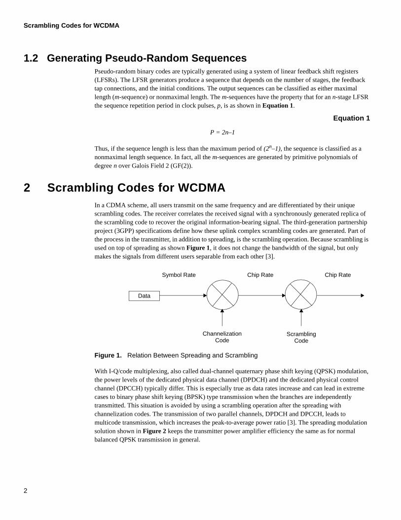
1.2 Generating Pseudo-Random SequencesPseudo-random binary codes are typically generated using a system of linear feedback shift registers (LFSRs). The LFSR generators produce a sequence that depends on the number of stages, the feedback tap connections, and the initial conditions. The output sequences can be classified as either maximal length (m-sequence) or nonmaximal length. The m-sequences have the property that for an n-stage LFSR the sequence repetition period in clock pulses, p, is as shown in Equation 1.
Equation 1
Thus, if the sequence length is less than the maximum period of (2n–1), the sequence is classified as a nonmaximal length sequence. In fact, all the m-sequences are generated by primitive polynomials of degree n over Galois Field 2 (GF(2)).
2 Scrambling Codes for WCDMAIn a CDMA scheme, all users transmit on the same frequency and are differentiated by their unique scrambling codes. The receiver correlates the received signal with a synchronously generated replica of the scrambling code to recover the original information-bearing signal. The third-generation partnership project (3GPP) specifications define how these uplink complex scrambling codes are generated. Part of the process in the transmitter, in addition to spreading, is the scrambling operation. Because scrambling is used on top of spreading as shown Figure 1, it does not change the bandwidth of the signal, but only makes the signals from different users separable from each other [3].
Figure 1. Relation Between Spreading and Scrambling
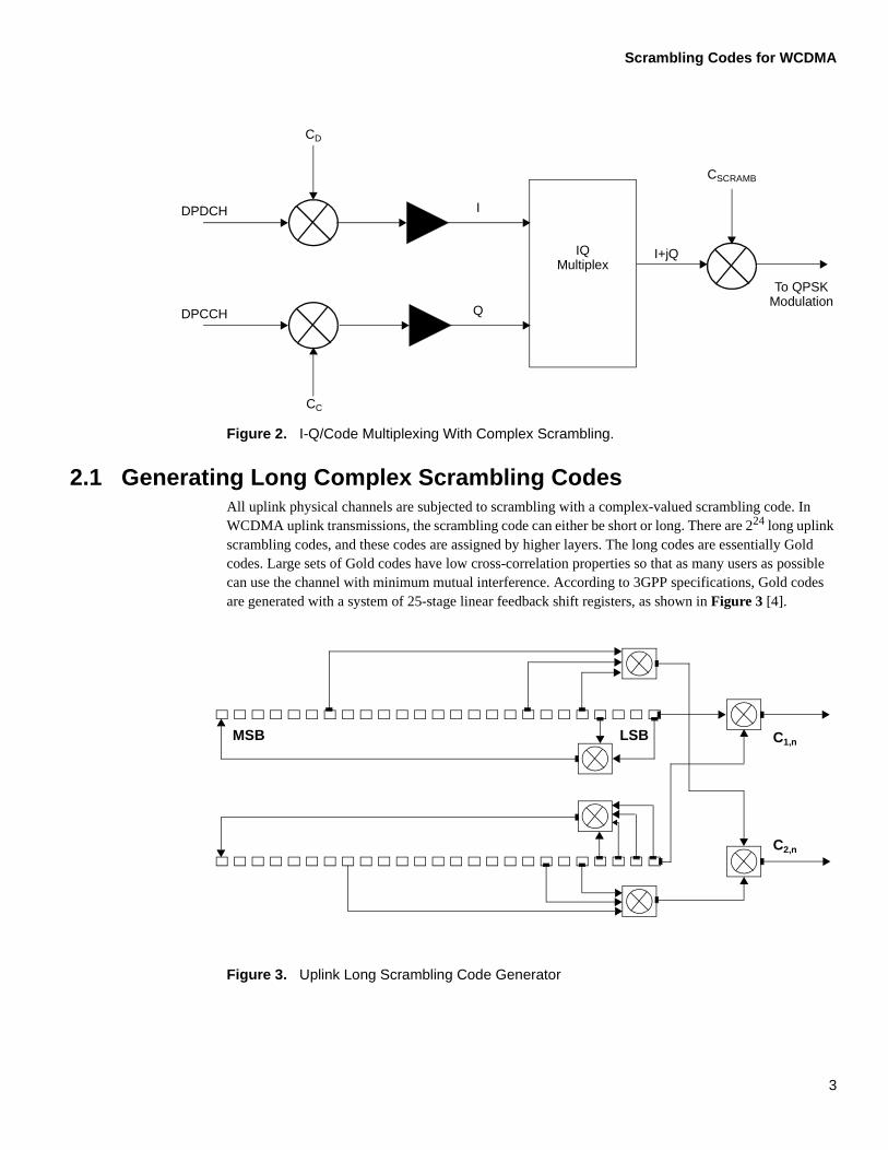
With I-Q/code multiplexing, also called dual-channel quaternary phase shift keying (QPSK) modulation, the power levels of the dedicated physical data channel (DPDCH) and the dedicated physical control channel (DPCCH) typically differ. This is especially true as data rates increase and can lead in extreme cases to binary phase shift keying (BPSK) type transmission when the branches are independently transmitted. This situation is avoided by using a scrambling operation after the spreading with channelization codes. The transmission of two parallel channels, DPDCH and DPCCH, leads to multicode transmission, which increases the peak-to-average power ratio [3]. The spreading modulation solution shown in Figure 2 keeps the transmitter power amplifier efficiency the same as for normal balanced QPSK transmission in general.
P = 2n–1
Data
Symbol Rate Chip Rate Chip Rate
ChannelizationCode
ScramblingCode
2
Scrambling Codes for WCDMA
Figure 2. I-Q/Code Multiplexing With Complex Scrambling.
2.1 Generating Long Complex Scrambling CodesAll uplink physical channels are subjected to scrambling with a complex-valued scrambling code. In WCDMA uplink transmissions, the scrambling code can either be short or long. There are 224 long uplink scrambling codes, and these codes are assigned by higher layers. The long codes are essentially Gold codes. Large sets of Gold codes have low cross-correlation properties so that as many users as possible can use the channel with minimum mutual interference. According to 3GPP specifications, Gold codes are generated with a system of 25-stage linear feedback shift registers, as shown in Figure 3 [4].
Figure 3. Uplink Long Scrambling Code Generator
IQMultiplex
I
Q
I+jQ
To QPSKModulation
CSCRAMB
CD
CC
DPDCH
DPCCH
MSB LSB C1,n
C2,n
3

Scrambling Codes for WCDMA
These 25-degree generator polynomials are truncated to the 10 ms frame length that results in 38400 chips at the rate of 3.84 Mcps. The long scrambling sequences, c1,n and c2,n, are constructed from a position-wise modulo 2 sum of 38400 chip segments of the two binary m-sequences. The two binary m-sequences are constructed using the following primitive polynomial over GF(2), as show in Figure 3. Furthermore, sequence c2,n is a 16,777,232 chip delayed version of sequence c1,n.
Equation 2
Equation 3
Let x, and y be the two m-sequences that are constructed from primitive polynomials of Equation 2 and Equation 3, respectively. The resulting sequences constitute segments of a set of Gold sequences. Now, let n23 ... n0 be the 24-bit binary representation of the scrambling sequence number n with n0 as the least significant bit. The x sequence depends on the chosen scrambling sequence number n and is denoted as xn in the sequel. Furthermore, let xn(i) and y(i) denote the i:th symbol of the sequences xn and y, respectively. The m-sequences xn and y are constructed as follows:
1. Initial conditions:
Equation 4
Equation 5
2. Recursive definition of subsequent symbols:
Equation 6
. Equation 7
3. Binary Gold sequence zn:
Equation 8
X25 + X3 + 1
X25 + X3 + X2 + X + 1
xn(0) = n0, xn(1) = n1, ..., xn(22) = n22, xn(23) = n23, xn(24) = 1
y(0) = y(1) = ... = y(23) = y(24) = 1
xn(i+25) = xn(i+3) + xn(i) modulo 2, i=0, ..., 225-27
y(i+25) = y(i+3) + y(i+2) + y(i+1) + y(i) modulo 2, i=0, ..., 225-27
zn(i) = xn(i) + y(i) modulo 2, i=0, ..., 225-2
4
Scrambling Codes for WCDMA
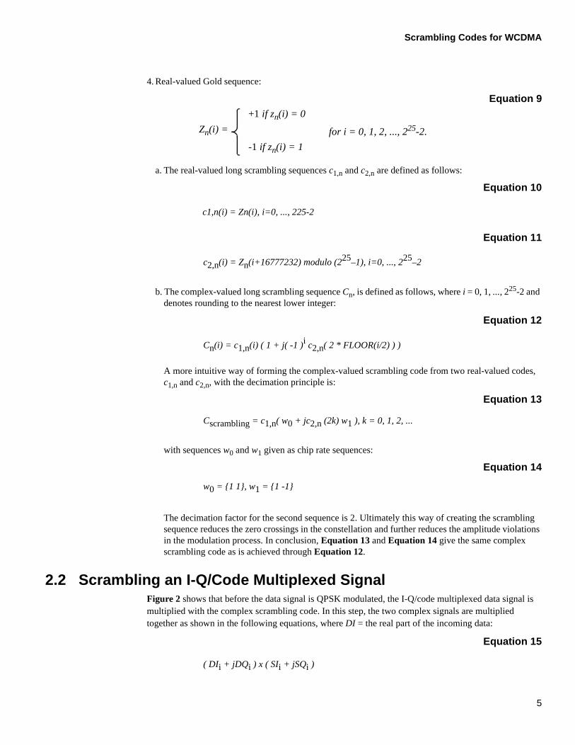
4. Real-valued Gold sequence:
Equation 9
a. The real-valued long scrambling sequences c1,n and c2,n are defined as follows:
Equation 10
Equation 11
b. The complex-valued long scrambling sequence Cn, is defined as follows, where i = 0, 1, ..., 225-2 and denotes rounding to the nearest lower integer:
Equation 12
A more intuitive way of forming the complex-valued scrambling code from two real-valued codes, c1,n and c2,n, with the decimation principle is:
Equation 13
with sequences w0 and w1 given as chip rate sequences:
Equation 14
The decimation factor for the second sequence is 2. Ultimately this way of creating the scrambling sequence reduces the zero crossings in the constellation and further reduces the amplitude violations in the modulation process. In conclusion, Equation 13 and Equation 14 give the same complex scrambling code as is achieved through Equation 12.
2.2 Scrambling an I-Q/Code Multiplexed SignalFigure 2 shows that before the data signal is QPSK modulated, the I-Q/code multiplexed data signal is multiplied with the complex scrambling code. In this step, the two complex signals are multiplied together as shown in the following equations, where DI = the real part of the incoming data:
Equation 15
Zn(i) =
+1 if zn(i) = 0
-1 if zn(i) = 1
for i = 0, 1, 2, ..., 225-2.
c1,n(i) = Zn(i), i=0, ..., 225-2
c2,n(i) = Zn(i+16777232) modulo (225–1), i=0, ..., 225–2
Cn(i) = c1,n(i) ( 1 + j( -1 )i c2,n( 2 * FLOOR(i/2) ) )
Cscrambling = c1,n( w0 + jc2,n (2k) w1 ), k = 0, 1, 2, ...
w0 = {1 1}, w1 = {1 -1}
( DIi + jDQi ) x ( SIi + jSQi )
5
Software Implementation on the StarCore SC140 Core
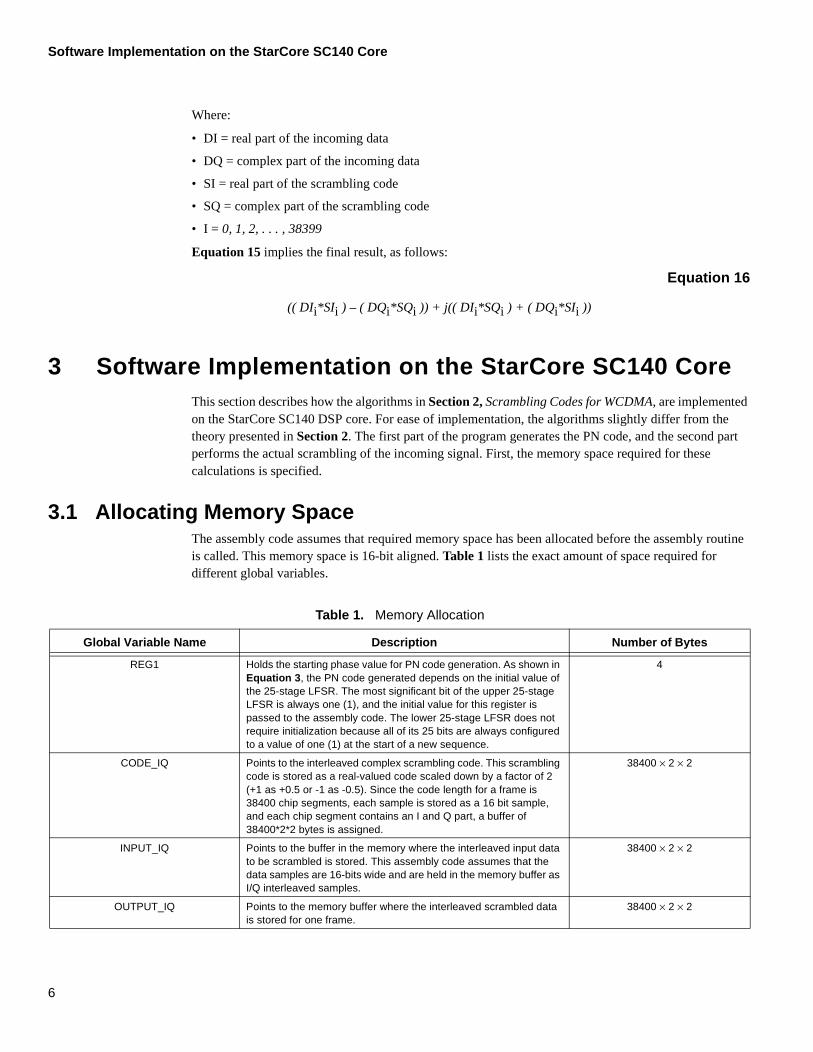
Where:
• DI = real part of the incoming data
• DQ = complex part of the incoming data
• SI = real part of the scrambling code
• SQ = complex part of the scrambling code
• I = 0, 1, 2, . . . , 38399
Equation 15 implies the final result, as follows:
Equation 16
3 Software Implementation on the StarCore SC140 CoreThis section describes how the algorithms in Section 2, Scrambling Codes for WCDMA, are implemented on the StarCore SC140 DSP core. For ease of implementation, the algorithms slightly differ from the theory presented in Section 2. The first part of the program generates the PN code, and the second part performs the actual scrambling of the incoming signal. First, the memory space required for these calculations is specified.
3.1 Allocating Memory SpaceThe assembly code assumes that required memory space has been allocated before the assembly routine is called. This memory space is 16-bit aligned. Table 1 lists the exact amount of space required for different global variables.
Table 1. Memory Allocation
Global Variable Name Description Number of Bytes
REG1 Holds the starting phase value for PN code generation. As shown in Equation 3, the PN code generated depends on the initial value of the 25-stage LFSR. The most significant bit of the upper 25-stage LFSR is always one (1), and the initial value for this register is passed to the assembly code. The lower 25-stage LFSR does not require initialization because all of its 25 bits are always configured to a value of one (1) at the start of a new sequence.
4
CODE_IQ Points to the interleaved complex scrambling code. This scrambling code is stored as a real-valued code scaled down by a factor of 2 (+1 as +0.5 or -1 as -0.5). Since the code length for a frame is 38400 chip segments, each sample is stored as a 16 bit sample, and each chip segment contains an I and Q part, a buffer of 38400*2*2 bytes is assigned.
38400 × 2 × 2
INPUT_IQ Points to the buffer in the memory where the interleaved input data to be scrambled is stored. This assembly code assumes that the data samples are 16-bits wide and are held in the memory buffer as I/Q interleaved samples.
38400 × 2 × 2
OUTPUT_IQ Points to the memory buffer where the interleaved scrambled data is stored for one frame.
38400 × 2 × 2
(( DIi*SIi ) – ( DQi*SQi )) + j(( DIi*SQi ) + ( DQi*SIi ))
6
Software Implementation on the StarCore SC140 Core
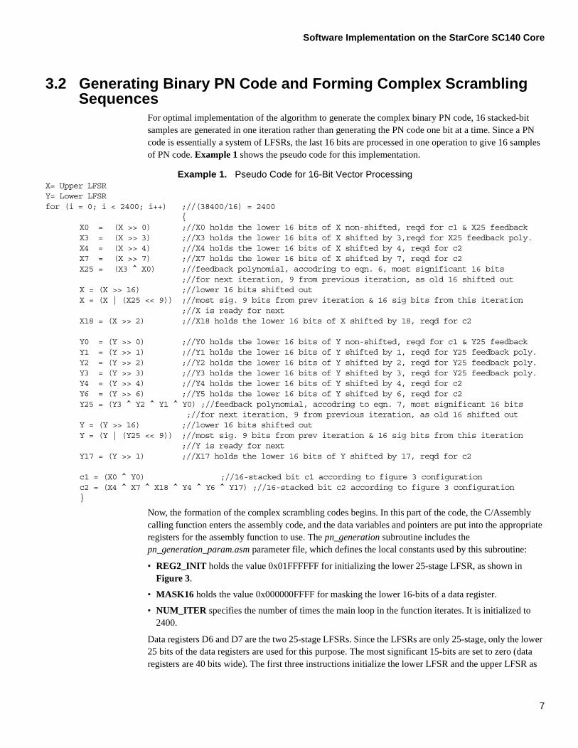
3.2 Generating Binary PN Code and Forming Complex ScramblingSequences
For optimal implementation of the algorithm to generate the complex binary PN code, 16 stacked-bit samples are generated in one iteration rather than generating the PN code one bit at a time. Since a PN code is essentially a system of LFSRs, the last 16 bits are processed in one operation to give 16 samples of PN code. Example 1 shows the pseudo code for this implementation.
Example 1. Pseudo Code for 16-Bit Vector ProcessingX= Upper LFSRY= Lower LFSRfor (i = 0; i < 2400; i++) ;//(38400/16) = 2400
{X0 = (X >> 0) ;//X0 holds the lower 16 bits of X non-shifted, reqd for c1 & X25 feedbackX3 = (X >> 3) ;//X3 holds the lower 16 bits of X shifted by 3,reqd for X25 feedback poly.X4 = (X >> 4) ;//X4 holds the lower 16 bits of X shifted by 4, reqd for c2X7 = (X >> 7) ;//X7 holds the lower 16 bits of X shifted by 7, reqd for c2X25 = (X3 ^ X0) ;//feedback polynomial, accodring to eqn. 6, most significant 16 bits
;//for next iteration, 9 from previous iteration, as old 16 shifted outX = (X >> 16) ;//lower 16 bits shifted outX = (X | (X25 << 9)) ;//most sig. 9 bits from prev iteration & 16 sig bits from this iteration
;//X is ready for nextX18 = (X >> 2) ;//X18 holds the lower 16 bits of X shifted by 18, reqd for c2
Y0 = (Y >> 0) ;//Y0 holds the lower 16 bits of Y non-shifted, reqd for c1 & Y25 feedbackY1 = (Y >> 1) ;//Y1 holds the lower 16 bits of Y shifted by 1, reqd for Y25 feedback poly.Y2 = (Y >> 2) ;//Y2 holds the lower 16 bits of Y shifted by 2, reqd for Y25 feedback poly.Y3 = (Y >> 3) ;//Y3 holds the lower 16 bits of Y shifted by 3, reqd for Y25 feedback poly.Y4 = (Y >> 4) ;//Y4 holds the lower 16 bits of Y shifted by 4, reqd for c2Y6 = (Y >> 6) ;//Y5 holds the lower 16 bits of Y shifted by 6, reqd for c2Y25 = (Y3 ^ Y2 ^ Y1 ^ Y0) ;//feedback polynomial, accodring to eqn. 7, most significant 16 bits
;//for next iteration, 9 from previous iteration, as old 16 shifted outY = (Y >> 16) ;//lower 16 bits shifted outY = (Y | (Y25 << 9)) ;//most sig. 9 bits from prev iteration & 16 sig bits from this iteration
;//Y is ready for nextY17 = (Y >> 1) ;//X17 holds the lower 16 bits of Y shifted by 17, reqd for c2
c1 = (X0 ^ Y0) ;//16-stacked bit c1 according to figure 3 configurationc2 = (X4 ^ X7 ^ X18 ^ Y4 ^ Y6 ^ Y17) ;//16-stacked bit c2 according to figure 3 configuration}
Now, the formation of the complex scrambling codes begins. In this part of the code, the C/Assembly calling function enters the assembly code, and the data variables and pointers are put into the appropriate registers for the assembly function to use. The pn_generation subroutine includes the pn_generation_param.asm parameter file, which defines the local constants used by this subroutine:
• REG2_INIT holds the value 0x01FFFFFF for initializing the lower 25-stage LFSR, as shown in Figure 3.
• MASK16 holds the value 0x000000FFFF for masking the lower 16-bits of a data register.
• NUM_ITER specifies the number of times the main loop in the function iterates. It is initialized to 2400.
Data registers D6 and D7 are the two 25-stage LFSRs. Since the LFSRs are only 25-stage, only the lower 25 bits of the data registers are used for this purpose. The most significant 15-bits are set to zero (data registers are 40 bits wide). The first three instructions initialize the lower LFSR and the upper LFSR as
7

Software Implementation on the StarCore SC140 Core
ored
shown in Figure 3 according to the initialization value that is stored in global variable REG1 for the upper LFSR (see Example 2). The last instruction loads address register R0 to point to the memory buffers to store the interleaved scrambling code samples I and Q.
Example 2. Setting Data and Address Registers
move.l #REG1,r0 ;//R0 points to initial value of upper LFSRmove.l #REG2_INIT,d7 ;//D7 is the lower LFSR move.l (r0),d6 ;//D6 is the upper LFSRmove.l #CODE_IQ,r0 ;//R0 points to where IQ scrambling code will be st
The program can be divided into two main parts:
1. Generating the binary PN code.
2. Forming the complex scrambling sequence.
3.2.1 Generating the Binary PN CodeGenerating the binary PN codes as stacked bits is accomplished following the algorithm shown in Example 1. The mainloop in the program generates the PN codes. The mainloop produces 16-bit stacked c1 and c2 PN code samples, as shown in Figure 3. As the routine starts, it executes instructions to set up the address and data registers before the code jumps into mainloop. The code sets up mainloop and the loop counter for the loop to perform 2400 iterations, as described in Example 3 (which shows a complete assembly code listing for generating the PN codes and the function for forming complex scrambling sequences, pn_generation.asm). Following is a step-by-step description of one iteration of the StarCore DSP code to demonstrate how it executes:
1. To determine c1and c2 for the PN code, we must determine the polynomials that are required. The c1 part of the PN code is a modulo 2 sum of the least significant bits of the X and Y registers.
a. The first 16-bit c1 sample is determined in instruction set ‘b’ of Example 3.
b. Inside the mainloop, it is calculated in instruction set ‘j’ and stored into the memory buffer in instruction set ‘d’.
2. Determining c2 requires a modulo 2 sum of several shifted polynomials:
— 4-bit shifted D6 (X4-instruction set ‘c’ and ‘k’)
— 7-bit shifted D6 (X7-instruction set ‘d’)
— 18-bit shifted D6 (X18-instruction set ‘h’)
— 4-bit shifted D7 (Y4-instruction set ‘d’)
— 6-bit shifted D7 (Y6-instruction set ‘e’)
— 17-bit shifted D7 (Y17-instruction set ‘i’)
The first 16-bit sample for c2 is determined in instruction set ‘j’ of code listing 3 and then stored in the memory buffer in the very next instruction set ‘k’.
3. Since the algorithm determines 16-bit samples and then shifts out the lower 16 bits from data registers D6 and D7, the determination of the feedback polynomials, X25 and Y25, is required:
a. The feedback polynomial X25 is a modulo 2 sum of the non-shifted lower 16 bits of D6 (X0 instruction set ‘a’ and ‘h’) and a 3-bit shifted version of D6 (X3 instruction set ‘b’ and ‘i’).
b. The first feedback X25 polynomial is determined in instruction set ‘c’ and then in instruction set ‘k’ in mainloop and is stored in register D1 in the same instruction set ‘k.’
c. The feedback polynomial Y25 is a modulo 2 sum of the non-shifted lower 16 bits of D7 (Y0 instruction set ‘a’ and ‘i’), 1-bit shifted D7 (Y1 instruction set ‘a’ and ‘i’), 2-bit shifted D7 (Y2 instruction set ‘b’ and ‘j’), and a 3-bit shifted D7 (Y3 instruction set ‘c’ and ‘k’).
8
Software Implementation on the StarCore SC140 Core
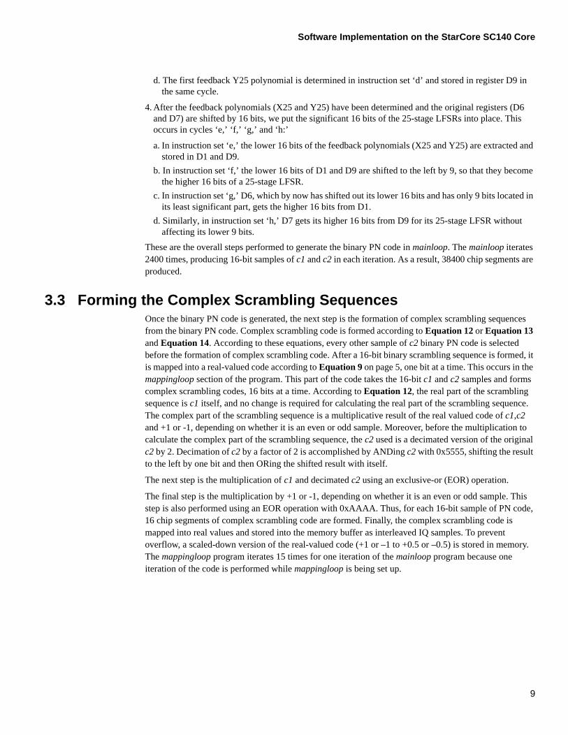
d. The first feedback Y25 polynomial is determined in instruction set ‘d’ and stored in register D9 in the same cycle.
4. After the feedback polynomials (X25 and Y25) have been determined and the original registers (D6 and D7) are shifted by 16 bits, we put the significant 16 bits of the 25-stage LFSRs into place. This occurs in cycles ‘e,’ ‘f,’ ‘g,’ and ‘h:’
a. In instruction set ‘e,’ the lower 16 bits of the feedback polynomials (X25 and Y25) are extracted and stored in D1 and D9.
b. In instruction set ‘f,’ the lower 16 bits of D1 and D9 are shifted to the left by 9, so that they become the higher 16 bits of a 25-stage LFSR.
c. In instruction set ‘g,’ D6, which by now has shifted out its lower 16 bits and has only 9 bits located in its least significant part, gets the higher 16 bits from D1.
d. Similarly, in instruction set ‘h,’ D7 gets its higher 16 bits from D9 for its 25-stage LFSR without affecting its lower 9 bits.
These are the overall steps performed to generate the binary PN code in mainloop. The mainloop iterates 2400 times, producing 16-bit samples of c1 and c2 in each iteration. As a result, 38400 chip segments are produced.
3.3 Forming the Complex Scrambling SequencesOnce the binary PN code is generated, the next step is the formation of complex scrambling sequences from the binary PN code. Complex scrambling code is formed according to Equation 12 or Equation 13 and Equation 14. According to these equations, every other sample of c2 binary PN code is selected before the formation of complex scrambling code. After a 16-bit binary scrambling sequence is formed, it is mapped into a real-valued code according to Equation 9 on page 5, one bit at a time. This occurs in the mappingloop section of the program. This part of the code takes the 16-bit c1 and c2 samples and forms complex scrambling codes, 16 bits at a time. According to Equation 12, the real part of the scrambling sequence is c1 itself, and no change is required for calculating the real part of the scrambling sequence. The complex part of the scrambling sequence is a multiplicative result of the real valued code of c1,c2 and +1 or -1, depending on whether it is an even or odd sample. Moreover, before the multiplication to calculate the complex part of the scrambling sequence, the c2 used is a decimated version of the original c2 by 2. Decimation of c2 by a factor of 2 is accomplished by ANDing c2 with 0x5555, shifting the result to the left by one bit and then ORing the shifted result with itself.
The next step is the multiplication of c1 and decimated c2 using an exclusive-or (EOR) operation.
The final step is the multiplication by +1 or -1, depending on whether it is an even or odd sample. This step is also performed using an EOR operation with 0xAAAA. Thus, for each 16-bit sample of PN code, 16 chip segments of complex scrambling code are formed. Finally, the complex scrambling code is mapped into real values and stored into the memory buffer as interleaved IQ samples. To prevent overflow, a scaled-down version of the real-valued code (+1 or –1 to +0.5 or –0.5) is stored in memory. The mappingloop program iterates 15 times for one iteration of the mainloop program because one iteration of the code is performed while mappingloop is being set up.
9
Software Implementation on the StarCore SC140 Core
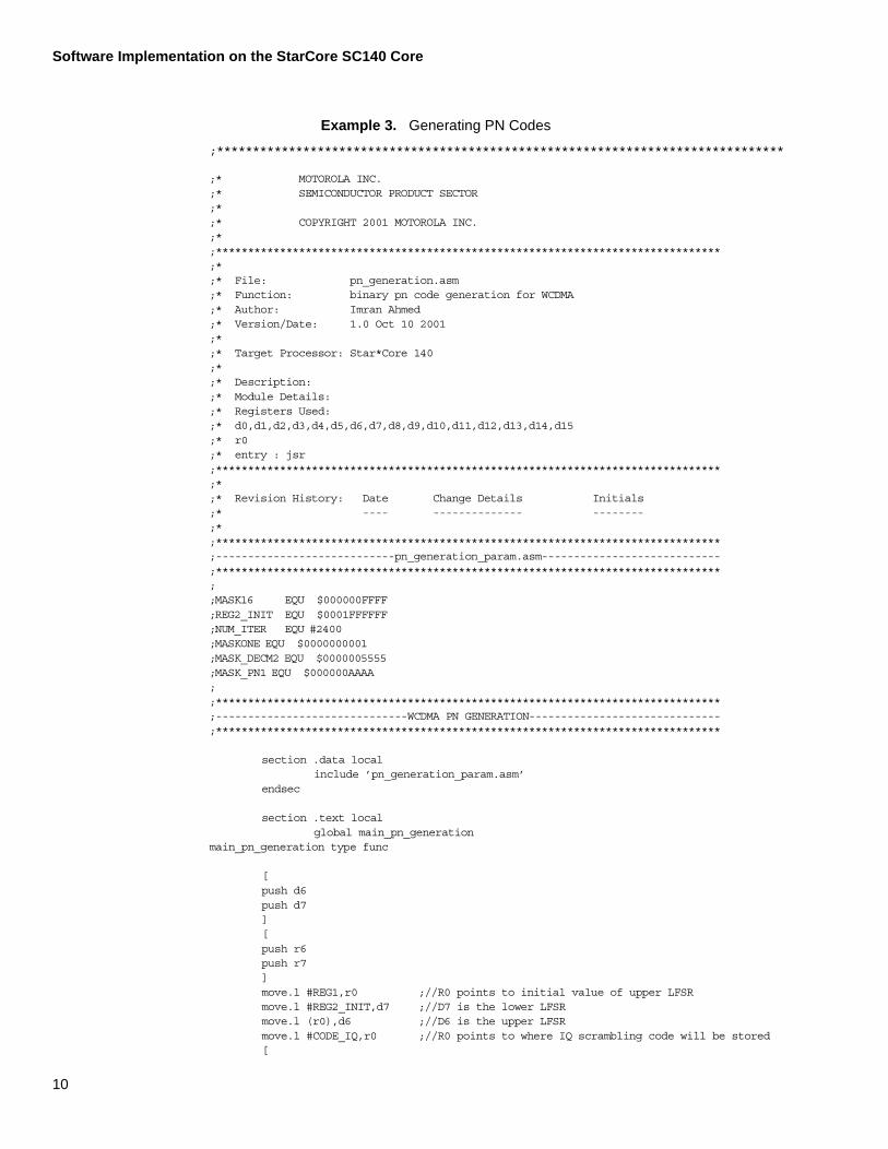
Example 3. Generating PN Codes
;*******************************************************************************
;* MOTOROLA INC.;* SEMICONDUCTOR PRODUCT SECTOR;*;* COPYRIGHT 2001 MOTOROLA INC.;*;*******************************************************************************;*;* File: pn_generation.asm;* Function: binary pn code generation for WCDMA;* Author: Imran Ahmed;* Version/Date: 1.0 Oct 10 2001;*;* Target Processor: Star*Core 140;*;* Description:;* Module Details:;* Registers Used:;* d0,d1,d2,d3,d4,d5,d6,d7,d8,d9,d10,d11,d12,d13,d14,d15;* r0;* entry : jsr;*******************************************************************************;*;* Revision History: Date Change Details Initials;* ---- -------------- --------;*;*******************************************************************************;----------------------------pn_generation_param.asm----------------------------;*******************************************************************************;;MASK16 EQU $000000FFFF;REG2_INIT EQU $0001FFFFFF;NUM_ITER EQU #2400;MASKONE EQU $0000000001;MASK_DECM2 EQU $0000005555;MASK_PN1 EQU $000000AAAA;;*******************************************************************************;------------------------------WCDMA PN GENERATION------------------------------;*******************************************************************************
section .data local include ’pn_generation_param.asm’ endsec section .text local global main_pn_generationmain_pn_generation type func
[push d6push d7][push r6push r7]move.l #REG1,r0 ;//R0 points to initial value of upper LFSRmove.l #REG2_INIT,d7 ;//D7 is the lower LFSRmove.l (r0),d6 ;//D6 is the upper LFSR
move.l #CODE_IQ,r0 ;//R0 points to where IQ scrambling code will be stored[
10
Software Implementation on the StarCore SC140 Core
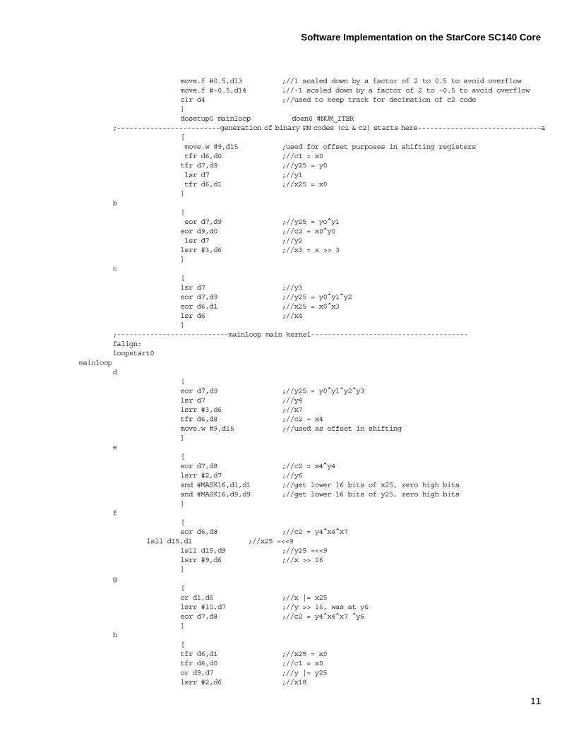
move.f #0.5,d13 ;//1 scaled down by a factor of 2 to 0.5 to avoid overflowmove.f #-0.5,d14 ;//-1 scaled down by a factor of 2 to -0.5 to avoid overflowclr d4 ;//used to keep track for decimation of c2 code]dosetup0 mainloop doen0 #NUM_ITER
;-------------------------generation of binary PN codes (c1 & c2) starts here------------------------------a [
move.w #9,d15 ;used for offset purposes in shifting registers tfr d6,d0 ;//c1 = x0
tfr d7,d9 ;//y25 = y0 lsr d7 ;//y1 tfr d6,d1 ;//x25 = x0
]b
[ eor d7,d9 ;//y25 = yo^y1
eor d9,d0 ;//c2 = x0^y0 lsr d7 ;//y2
lsrr #3,d6 ;//x3 = x >> 3 ]
c [ lsr d7 ;//y3 eor d7,d9 ;//y25 = y0^y1^y2 eor d6,d1 ;//x25 = x0^x3 lsr d6 ;//x4
];---------------------------mainloop main kernel--------------------------------------
falign:loopstart0
mainloopd
[ eor d7,d9 ;//y25 = y0^y1^y2^y3 lsr d7 ;//y4 lsrr #3,d6 ;//x7 tfr d6,d8 ;//c2 = x4 move.w #9,d15 ;//used as offset in shifting
]e
[ eor d7,d8 ;//c2 = x4^y4 lsrr #2,d7 ;//y6 and #MASK16,d1,d1 ;//get lower 16 bits of x25, zero high bits and #MASK16,d9,d9 ;//get lower 16 bits of y25, zero high bits ]
f[
eor d6,d8 ;//c2 = y4^x4^x7 lsll d15,d1 ;//x25 =<<9 lsll d15,d9 ;//y25 =<<9 lsrr #9,d6 ;//x >> 16 ]
g[
or d1,d6 ;//x |= x25 lsrr #10,d7 ;//y >> 16, was at y6 eor d7,d8 ;//c2 = y4^x4^x7 ^y6 ]
h[tfr d6,d1 ;//x25 = x0tfr d6,d0 ;//c1 = x0or d9,d7 ;//y |= y25
lsrr #2,d6 ;//x18
11
Software Implementation on the StarCore SC140 Core
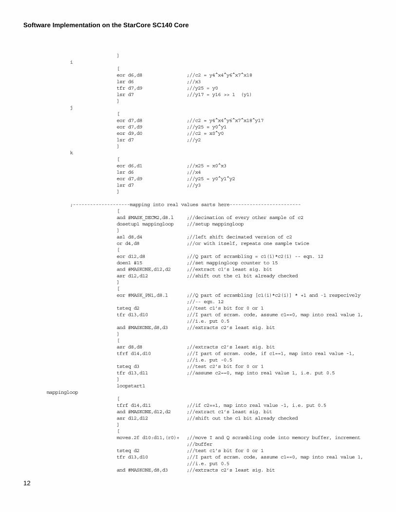
]i
[ eor d6,d8 ;//c2 = y4^x4^y6^x7^x18 lsr d6 ;//x3 tfr d7,d9 ;//y25 = y0 lsr d7 ;//y17 = y16 >> 1 (y1) ]
j[
eor d7,d8 ;//c2 = y4^x4^y6^x7^x18^y17 eor d7,d9 ;//y25 = y0^y1 eor d9,d0 ;//c2 = x0^y0 lsr d7 ;//y2 ]
k[
eor d6,d1 ;//x25 = x0^x3 lsr d6 ;//x4 eor d7,d9 ;//y25 = y0^y1^y2 lsr d7 ;//y3 ]
;--------------------mapping into real values sarts here-------------------------[and #MASK_DECM2,d8.l ;//decimation of every other sample of c2dosetup1 mappingloop ;//setup mappingloop
] asl d8,d4 ;//left shift decimated version of c2
or d4,d8 ;//or with itself, repeats one sample twice[eor d12,d8 ;//Q part of scrambling = c1(i)*c2(i) -- eqn. 12doen1 #15 ;//set mappingloop counter to 15and #MASKONE,d12,d2 ;//extract c1’s least sig. bitasr d12,d12 ;//shift out the c1 bit already checked][eor #MASK_PN1,d8.l ;//Q part of scrambling [c1(i)*c2(i)] * +1 and -1 respecively
;//-- eqn. 12tsteq d2 ;//test c1’s bit for 0 or 1tfr d13,d10 ;//I part of scram. code, assume c1==0, map into real value 1,
;//i.e. put 0.5and #MASKONE,d8,d3 ;//extracts c2’s least sig. bit][asr d8,d8 ;//extracts c2’s least sig. bittfrf d14,d10 ;//I part of scram. code, if c1==1, map into real value -1,
;//i.e. put -0.5tsteq d3 ;//test c2’s bit for 0 or 1tfr d13,d11 ;//assume c2==0, map into real value 1, i.e. put 0.5]loopstart1
mappingloop[tfrf d14,d11 ;//if c2==1, map into real value -1, i.e. put 0.5and #MASKONE,d12,d2 ;//extract c1’s least sig. bitasr d12,d12 ;//shift out the c1 bit already checked][moves.2f d10:d11,(r0)+ ;//move I and Q scrambling code into memory buffer, increment
;//buffertsteq d2 ;//test c1’s bit for 0 or 1tfr d13,d10 ;//I part of scram. code, assume c1==0, map into real value 1,
;//i.e. put 0.5and #MASKONE,d8,d3 ;//extracts c2’s least sig. bit
12
Software Implementation on the StarCore SC140 Core
13
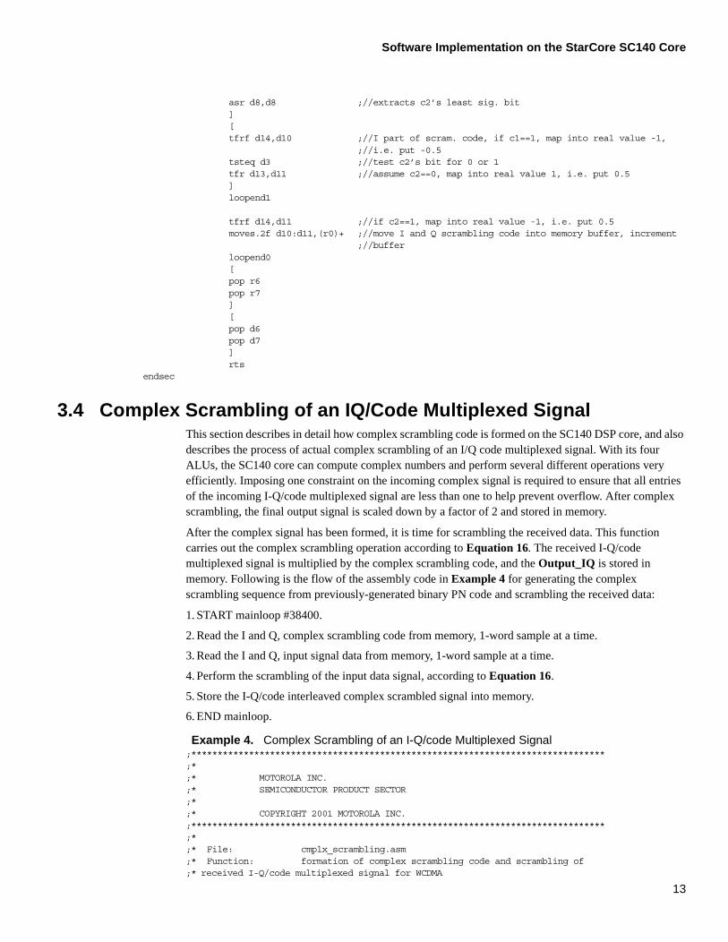
asr d8,d8 ;//extracts c2’s least sig. bit][tfrf d14,d10 ;//I part of scram. code, if c1==1, map into real value -1,
;//i.e. put -0.5tsteq d3 ;//test c2’s bit for 0 or 1tfr d13,d11 ;//assume c2==0, map into real value 1, i.e. put 0.5]loopend1
tfrf d14,d11 ;//if c2==1, map into real value -1, i.e. put 0.5moves.2f d10:d11,(r0)+ ;//move I and Q scrambling code into memory buffer, increment
;//bufferloopend0[pop r6pop r7][pop d6pop d7]rts
endsec
3.4 Complex Scrambling of an IQ/Code Multiplexed SignalThis section describes in detail how complex scrambling code is formed on the SC140 DSP core, and also describes the process of actual complex scrambling of an I/Q code multiplexed signal. With its four ALUs, the SC140 core can compute complex numbers and perform several different operations very efficiently. Imposing one constraint on the incoming complex signal is required to ensure that all entries of the incoming I-Q/code multiplexed signal are less than one to help prevent overflow. After complex scrambling, the final output signal is scaled down by a factor of 2 and stored in memory.
After the complex signal has been formed, it is time for scrambling the received data. This function carries out the complex scrambling operation according to Equation 16. The received I-Q/code multiplexed signal is multiplied by the complex scrambling code, and the Output_IQ is stored in memory. Following is the flow of the assembly code in Example 4 for generating the complex scrambling sequence from previously-generated binary PN code and scrambling the received data:
1. START mainloop #38400.
2. Read the I and Q, complex scrambling code from memory, 1-word sample at a time.
3. Read the I and Q, input signal data from memory, 1-word sample at a time.
4. Perform the scrambling of the input data signal, according to Equation 16.
5. Store the I-Q/code interleaved complex scrambled signal into memory.
6. END mainloop.
Example 4. Complex Scrambling of an I-Q/code Multiplexed Signal;*******************************************************************************;*;* MOTOROLA INC.;* SEMICONDUCTOR PRODUCT SECTOR;*;* COPYRIGHT 2001 MOTOROLA INC.;*******************************************************************************;*;* File: cmplx_scrambling.asm;* Function: formation of complex scrambling code and scrambling of ;* received I-Q/code multiplexed signal for WCDMA

Software Implementation on the StarCore SC140 Core
;* Author: Imran Ahmed;* Version/Date: 1.0 Oct 10 2001;*;* Target Processor: Star*Core 140;*;* Description:;* Module Details:;* Registers Used:;* d0,d1,d2,d3,d4,d5,d6,d7,d8,d9,d10,d11,d15;* r0,r2,r4;* entry : jsr;*******************************************************************************;*;* Revision History: Date Change Details Initials;* ---- -------------- --------;*;*******************************************************************************;--------------------------cmplx_scrambling_param.asm---------------------------;*******************************************************************************;;NUM_ITEREQU19199 ;//(38400-2)/2;INV_SQRT2 EQU #0.70710678;//1/sqrt(2);;*******************************************************************************;---------------------------WCDMA COMPLEX SCRAMBLING----------------------------;*******************************************************************************
section .data local include ’cmplx_scrambling_param.asm’ endsec
section .text localglobal main_cmplx_scrambling
main_cmplx_scrambling type func[push d6push d7][push r6push r7]move.l #INPUT_IQ,r0 ;//R0 -> received input signalmove.l #CODE_IQ,r4 ;//R4 -> complex scrambling signalmove.l #OUTPUT_IQ,r2 ;//R2 -> IQ complex scrambled signal to be storedmove.f #INV_SQRT2,d15 ;//(1/sqrt(2)), required for scrambling to keep the
;//energy of the srambled signal constantdosetup1 mainloop doen1 #NUM_ITER
[move.4f (r0)+,d0:d1:d2:d3 ;//move 2 input IQ samples from memory to data
;//registersmove.4f (r4)+,d4:d5:d6:d7 ;//move 2 scrambling IQ code samples from memory to
;//data registers][mpy d0,d4,d8 ;//(DI*SI) part from eqn. 16, 1st samplempy d0,d5,d9 ;//(DI*SQ) part from eqn. 16, 1st samplempy d2,d6,d10 ;//(DI*SI) part from eqn. 16, 2nd samplempy d2,d7,d11 ;//(DI*SQ) part from eqn. 16, 2nd sample]
14
Software Implementation on the StarCore SC140 Core
15
[mac -d1,d5,d8 ;//(-(DQ*SQ)) part from eqn. 16, 1st samplemac d1,d4,d9 ;//(DQ*SI) part from eqn. 16, 1st samplemac -d3,d7,d10 ;//(-(DQ*SQ)) part from eqn. 16, 2nd samplemac d3,d6,d11 ;//(DQ*SI) part from eqn. 16, 2nd sample]
;-------------------code and scaling to preserve the energy of the constellation-----------------------[
;-------------------code and scaling to preserve the energy of the constellation--------mpy d15,d8,d8 ;//(1/sqrt(2)) x (scrambled output I), 1st samplempy d15,d9,d9 ;//(1/sqrt(2)) x (scrambled output Q), 1st samplempy d15,d10,d10 ;//(1/sqrt(2)) x (scrambled output I), 2nd samplempy d15,d11,d11 ;//(1/sqrt(2)) x (scrambled output Q), 2nd sample][asl d8,d8 ;//output I scaling factor change from 4 to 2, 1st
;//sampleasl d9,d9 ;//output Q scaling factor change from 4 to 2, 1st
;//sampleasl d10,d10 ;//output I scaling factor change from 4 to 2, 2nd
;//sampleasl d11,d11 ;//output Q scaling factor change from 4 to 2, 2ndsample]
;----------------------------end of code to preserve energy of constellation--------------------
[move.4f (r0)+,d0:d1:d2:d3 ;//move 2 input IQ samples from memory to data
;//registersmove.4f (r4)+,d4:d5:d6:d7 ;//move 2 scrambling IQ code samples from memory to
;//data registers]
falignloopstart1
mainloop[moves.4f d8:d9:d10:d11,(r2)+ ;//move 2 complex scrambled IQ samples into memory
;//buffermpy d0,d4,d8 ;//(DI*SI) part from eqn. 16, 1st samplempy d0,d5,d9 ;//(DI*SQ) part from eqn. 16, 1st samplempy d2,d6,d10 ;//(DI*SI) part from eqn. 16, 2nd samplempy d2,d7,d11 ;//(DI*SQ) part from eqn. 16, 2nd sample][mac -d1,d5,d8 ;//(-(DQ*SQ)) part from eqn. 16, 1st samplemac d1,d4,d9 ;//(DQ*SI) part from eqn. 16, 1st samplemac -d3,d7,d10 ;//(-(DQ*SQ)) part from eqn. 16, 2nd samplemac d3,d6,d11 ;//(DQ*SI) part from eqn. 16, 2nd samplemove.4f (r0)+,d0:d1:d2:d3 ;//move 2 input IQ samples from memory to data
;//registersmove.4f (r4)+,d4:d5:d6:d7 ;//move 2 scrambling IQ code samples from memory to
;//data registers]
;-------------------code and scaling to preserve the energy of the constellation----------------[mpy d15,d8,d8 ;//(1/sqrt(2)) x (scrambled output I), 1st samplempy d15,d9,d9 ;//(1/sqrt(2)) x (scrambled output Q), 1st samplempy d15,d10,d10 ;//(1/sqrt(2)) x (scrambled output I), 2nd samplempy d15,d11,d11 ;//(1/sqrt(2)) x (scrambled output Q), 2nd sample]

Results
[asl d8,d8 ;//output I scaling factor change from 4 to 2, 1st
;//sampleasl d9,d9 ;//output Q scaling factor change from 4 to 2, 1st
;//sampleasl d10,d10 ;//output I scaling factor change from 4 to 2, 2nd
;//sampleasl d11,d11 ;//output Q scaling factor change from 4 to 2, 2nd
sample]
;----------------------------end of code to preserve energy of constellation--------------------loopend1
moves.4f d8:d9:d10:d11,(r2)+ ;//move 2 complex scrambled IQ samples into memory;//buffer
[pop r6pop r7][pop d6pop d7]rts
endsec
4 Results The plots in Figure 4 and Figure 5 show the corresponding Matlab and StarCore DSP results for the complex scrambled signal. As these figures indicate, the StarCore DSP and the Matlab results agree.
Figure 4. Real Part of the Complex Scrambled Signal (Chips 19150–19250)
1.915 1.916 1.917 1.918 1.919 1.92 1.921 1.922 1.923 1.924 1.925
x 104
−2
−1.5
−1
−0.5
0
0.5
1
1.5
2Real part of Scrambled Signal
value
of c
hip in
cons
tella
tion
chip segment number
Green − DSP output
Blue −− Matlab output
16
Results
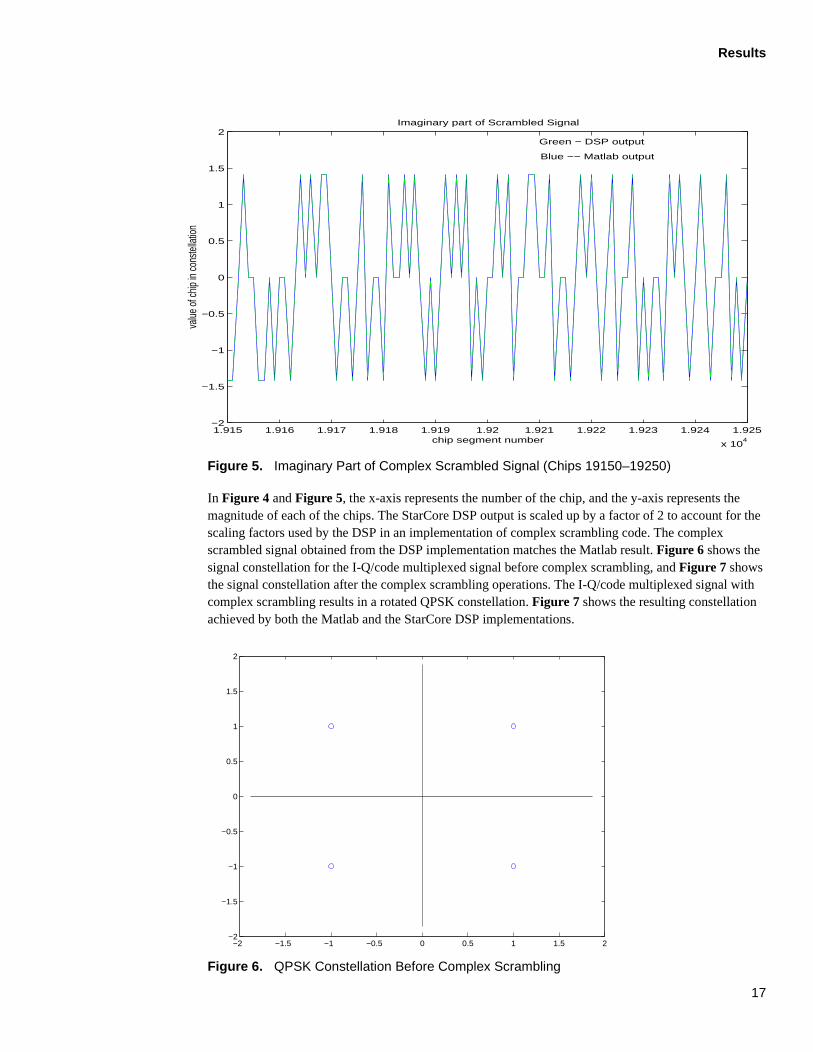
Figure 5. Imaginary Part of Complex Scrambled Signal (Chips 19150–19250)
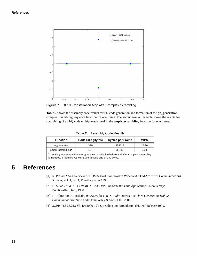
In Figure 4 and Figure 5, the x-axis represents the number of the chip, and the y-axis represents the magnitude of each of the chips. The StarCore DSP output is scaled up by a factor of 2 to account for the scaling factors used by the DSP in an implementation of complex scrambling code. The complex scrambled signal obtained from the DSP implementation matches the Matlab result. Figure 6 shows the signal constellation for the I-Q/code multiplexed signal before complex scrambling, and Figure 7 shows the signal constellation after the complex scrambling operations. The I-Q/code multiplexed signal with complex scrambling results in a rotated QPSK constellation. Figure 7 shows the resulting constellation achieved by both the Matlab and the StarCore DSP implementations.
Figure 6. QPSK Constellation Before Complex Scrambling
1.915 1.916 1.917 1.918 1.919 1.92 1.921 1.922 1.923 1.924 1.925
x 104
−2
−1.5
−1
−0.5
0
0.5
1
1.5
2Imaginary part of Scrambled Signal
value
of c
hip in
cons
tella
tion
chip segment number
Green − DSP output
Blue −− Matlab output
−2 −1.5 −1 −0.5 0 0.5 1 1.5 2−2
−1.5
−1
−0.5
0
0.5
1
1.5
2
17
References
Figure 7. QPSK Constellation Map after Complex Scrambling
Table 2 shows the assembly code results for PN code generation and formation of the pn_generation complex scrambling sequence function for one frame. The second row of the table shows the results for scrambling of an I-Q/code multiplexed signal in the cmplx_scrambling function for one frame.
5 References[1] R. Prasad, “An Overview of CDMA Evolution Toward Wideband CDMA,” IEEE Communications
Surveys, vol. 1, no. 1, Fourth Quarter 1998.
[2] B. Sklar, DIGITAL COMMUNICATIONS Fundamentals and Applications. New Jersey: Prentice-Hall, Inc., 1988.
[3] H Holma and A. Toskala, WCDMA for UMTS-Radio Access For Third Generation Mobile Communications. New York: John Wiley & Sons, Ltd., 2001.
[4] 3GPP, “TS 25.213 V3.40 (2000-12): Spreading and Modulation (FDD),” Release 1999.
Table 2. Assembly Code Results
Function Code Size (Bytes) Cycles per Frame MIPS
pn_generation 330 153618 15.36
cmplx_scrambling* 124 38411 3.84
* If scaling to preserve the energy of the constellation before and after complex scrambling is included, it requires 7.6 MIPS with a code size of 180 bytes.
−2 −1.5 −1 −0.5 0 0.5 1 1.5 2−2
−1.5
−1
−0.5
0
0.5
1
1.5
2
X (Blue) − DSP output
O (Green) − Matlab output
18

References
19

HOW TO REACH US:
USA/EUROPE/LOCATIONS NOT LISTED:
Motorola Literature Distribution; P.O. Box 5405, Denver, Colorado 80217 1-303-675-2140 or 1-800-441-2447
JAPAN:
Motorola Japan Ltd.; SPS, Technical Information Center, 3-20-1, Minami-Azabu Minato-ku, Tokyo 106-8573 Japan81-3-3440-3569
ASIA/PACIFIC:
Motorola Semiconductors H.K. Ltd.; Silicon Harbour Centre, 2 Dai King Street, Tai Po Industrial Estate, Tai Po, N.T., Hong Kong852-26668334
TECHNICAL INFORMATION CENTER:
1-800-521-6274
Information in this document is provided solely to enable system and software implementers to use
Motorola products. There are no express or implied copyright licenses granted hereunder to design
or fabricate any integrated circuits or integrated circuits based on the information in this document.
Motorola reserves the right to make changes without further notice to any products herein. Motorola
makes no warranty, representation or guarantee regarding the suitability of its products for any
particular purpose, nor does Motorola assume any liability arising out of the application or use of any
product or circuit, and specifically disclaims any and all liability, including without limitation
consequential or incidental damages. “Typical” parameters which may be provided in Motorola data
sheets and/or specifications can and do vary in different applications and actual performance may
vary over time. All operating parameters, including “Typicals” must be validated for each customer
application by customer’s technical experts. Motorola does not convey any license under its patent
rights nor the rights of others. Motorola products are not designed, intended, or authorized for use as
components in systems intended for surgical implant into the body, or other applications intended to
support or sustain life, or for any other application in which the failure of the Motorola product could
create a situation where personal injury or death may occur. Should Buyer purchase or use Motorola
products for any such unintended or unauthorized application, Buyer shall indemnify and hold
Motorola and its officers, employees, subsidiaries, affiliates, and distributors harmless against all
claims, costs, damages, and expenses, and reasonable attorney fees arising out of, directly or
AN2254/D
HOME PAGE:
http://motorola.com/semiconductorsindirectly, any claim of personal injury or death associated with such unintended or unauthorized use,
even if such claim alleges that Motorola was negligent regarding the design or manufacture of the part.
Motorola and the Stylized M Logo are registered in the U.S. Patent and Trademark Office. digital dna is a trademark and StarCore is a registered trademark of Motorola, Inc. All other product or service names are the property of their respective owners. Motorola, Inc. is an Equal Opportunity/Affirmative Action Employer.
© Motorola, Inc. 2002