SCR Triggering Circuits Scientech 2702 Learning Material Ver 1.1 ...
16
SCR Triggering Circuits Scientech 2702 Learning Material Ver 1.1 An ISO 9001:2008 company Scientech Technologies Pvt. Ltd. 94, Electronic Complex, Pardesipura, Indore - 452 010 India, + 91-731 4211100, : [email protected] , : www.ScientechWorld.com
Transcript of SCR Triggering Circuits Scientech 2702 Learning Material Ver 1.1 ...

SCR Triggering CircuitsScientech 2702
Learning MaterialVer 1.1
An ISO 9001:2008 companyScientech Technologies Pvt. Ltd.94, Electronic Complex, Pardesipura, Indore - 452 010 India,
+ 91-731 4211100, : [email protected] , : www.ScientechWorld.com

Scientech 2702
Scientech Technologies Pvt. Ltd. 2

Scientech 2702
Scientech Technologies Pvt. Ltd. 3
SCR Triggering CircuitsScientech 2702
Table of Contents1. Introduction 4
2. Features 53. Technical Specifications 6
4. Theory 75. Experiments
Experiment 1 9Resistor Triggering Circuit
Experiment 2 11Resistor Capacitor Triggering circuit (Half wave)
Experiment 3Resistor Capacitor Triggering circuit (Full wave) 13
6. Datasheet 16
7. Warranty 178. List of Accessories 17
Scientech 2702
Scientech Technologies Pvt. Ltd. 4
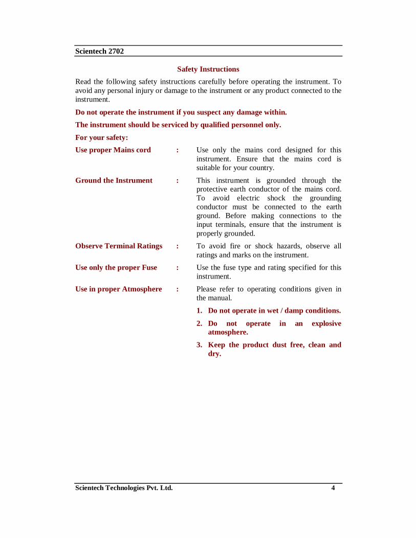
Safety InstructionsRead the following safety instructions carefully before operating the instrument. Toavoid any personal injury or damage to the instrument or any product connected to theinstrument.
Do not operate the instrument if you suspect any damage within.The instrument should be serviced by qualified personnel only.
For your safety:Use proper Mains cord : Use only the mains cord designed for this
instrument. Ensure that the mains cord issuitable for your country.
Ground the Instrument : This instrument is grounded through theprotective earth conductor of the mains cord.To avoid electric shock the groundingconductor must be connected to the earthground. Before making connections to theinput terminals, ensure that the instrument isproperly grounded.
Observe Terminal Ratings : To avoid fire or shock hazards, observe allratings and marks on the instrument.
Use only the proper Fuse : Use the fuse type and rating specified for thisinstrument.
Use in proper Atmosphere : Please refer to operating conditions given inthe manual.
1. Do not operate in wet / damp conditions.
2. Do not operate in an explosiveatmosphere.
3. Keep the product dust free, clean anddry.

Scientech 2702
Scientech Technologies Pvt. Ltd. 5
IntroductionScientech 2702 is a platform which is very useful for Students to understand variousthyristor firing methods like R, RC half wave, RC full wave. This platform isprovided with in built power supply, sockets for making interconnection in the circuit& exhaustive learning material.
Scientech 2702
Scientech Technologies Pvt. Ltd. 6
Features
In built Power Supply
Easy to operate and understand
Three firing circuits on single board
Gradual firing angle control
Test points for observe output of different circuits
Sockets to make different connections
On board AC sources of 18 V-0 V-18 V

Scientech 2702
Scientech Technologies Pvt. Ltd. 7
Technical Specifications
On board AC source : 18 V - 0 V - 18 V
On board firing circuits :R Triggering CircuitRC Half Wave Triggering Circuit
RC Full Wave Triggering Circuit
Interconnections : 2 mm sockets (Gold plated)
Firing angle variation : Gradually variation using firing control POTSSCR assembly : 4 SCRs 2P4M, 400 V/2A
Test points : 8 nos (Gold plated)Dimensions (mm) : W 420 x D 255 x H 100
Power Supply (Mains) : 110V - 260V AC, 50/60HzWeight : 1 Kg. (approximately)
Operating Conditions : 0-400 C, 80% RHLearning material : CD (Theory, procedure, reference results, etc),
Online (optional)

Scientech 2702
Scientech Technologies Pvt. Ltd. 8
TheoryThe most common, reliable and efficient method for controlling the conduction periodof a Thyristors is by means of gate voltage control. The gate voltage control circuit isalso called as the triggering circuit or Triggering circuit. Normally these circuits wereused in low power semiconductor devices. The various triggering circuits are
a. Resistor Triggering:
A Diode-resistance combination circuit is the simplest way of obtaining thetrigger pulse. The most basic method of obtaining the gate current from themain ac source is: whenever the anode is positive with respect to the cathode.When the thyristor has triggered in the positive half cycle of the input voltage,the anode-cathode voltage of the thyristor drops to the conduction value( 1.5V)and the gate current decreases to zero(due to the availability of the lowresistance path). The resistor R limits the peak gate current value, and the diodeD prevents a reverse voltage during the negative half-cycle of the ac input. Byvarying the value of the resistance R1, the conduction period of the thyristor canbe controlled. The value of the resistance R is such that the value of the gatecurrent should not exceed the rated maximum value.
Circuit at minimum power settingFigure 1
b. Resistor-capacitor Triggering:The triggering angle control limitation of the diode resistance triggering circuitcan be overcome by the diode-resistance-capacitance triggering circuit. Thefigure shows the RC-half wave trigger circuit. The conduction period can becontrolled over the full 180° range. By varying the value of R1, the trigger canbe controlled from 0 to . During the positive half cycle, the capacitor Ccharges to the trigger voltage of the thyristor in a time determined by the RCtime constant and the applied anode voltage. During the negative half cycle, thecapacitor charges to the peak supply voltage at t = (- /2). After this period,the supply voltage decreases and reaches zero at t = 0.During this period thecapacitor voltage becomes positive during the positive half cycle of the ac input,the capacitor begins to charge through the variable resistance R1, in theopposite direction and as soon as it charges to a positive voltage equal to thegate trigger voltage, the thyristor turns ON. Here the diode D1 is used to preventthe negative voltage between the gate and the cathode through the diode D2during the negative half-cycle.

Scientech 2702
Scientech Technologies Pvt. Ltd. 9
Figure 2c. Resistor-Capacitor-Full wave triggering:
In the RC-half wave trigger circuit power can be delivered to the load onlyduring the positive half cycle of es because the SCR conducts only when it isforward biased. This limitation can be overcome in several ways; here the acline voltage is converted to pulsating dc by the full-wave diode bridge. Thisallows the SCR to be triggered ON for both half cycle of the line voltage,which doubles the available power to the load. The initial voltage, by which thecapacitor C charges is almost zero. Capacitor C is set to this low positivevoltage (upper plate positive) by the clamping action of the SCR gate. When thecapacitor charges to a voltage equal to Vgt, SCR triggers and rectified voltageEdc appears across load as eL.
RC Triggering (Full Wave)Figure 3

Scientech 2702
Scientech Technologies Pvt. Ltd. 10
Experiment 1Objective:To study the Resistor Triggering Circuit
Equipments Needed:1. Power Electronics Board Scientech 2702.2. 2 mm patch cords.
3. Oscilloscope-Scientech 803/831, or equivalent
Circuit diagram:The circuit diagram for SCR Triggering circuits is as follows:
Figure 4

Scientech 2702
Scientech Technologies Pvt. Ltd. 11
Procedure:1. Connect the potentiometer points ‘D’ to point ‘d1’ and ‘E’ to point ‘e1’.
2. Connect the SCR points ‘A’ to point ‘a1’, ‘B’ to point ‘b1’ and ‘C’ to point ‘c1’.
3. Rotate the potentiometer ‘P1’ fully in clockwise direction.
4. Switch ‘On’ the power supply.5. Connect the oscilloscope CH.I between the load test point ‘t1’ and ‘t2’ and
observe the Phase angle and voltage.6. Now, connect the oscilloscope probe across the thyristor and observe the
waveform.
7. Vary the potentiometer slowly; you can see the phase angle variation.
8. Repeat the experiment from step 5 for various angles and plot the graphs.
Observation Table 1:
S. No. Load voltage(V) Phase Angle ( )
1.
2.
3.
4.
5.
6.

Scientech 2702
Scientech Technologies Pvt. Ltd. 12
Experiment 2Objective:To study the Resistor-Capacitor Triggering Circuit (Half wave)
Equipments Needed:1. Power Electronics Board Scientech 2702.2. 2 mm patch cords.
3. Oscilloscope-Scientech 803/831, or equivalent
Circuit diagram:The circuit diagram for SCR Triggering circuits is as follows:
Figure 5

Scientech 2702
Scientech Technologies Pvt. Ltd. 13
Procedure:1. Connect the potentiometer points ‘D’ to point ‘d2’ and ‘E’ to point ‘e2’.
2. Connect the SCR points ‘A’ to point ‘a1’, ‘B’ to point ‘b2’ and ‘C’ to point ‘c2’.
3. Rotate the potentiometers ‘P1’ fully in the anticlockwise direction.
4. Switch ‘On’ the power supply.5. Connect the oscilloscope probe between the load test point ‘t3’ and ‘t4’ and
observe the Phase angle and voltage.6. Now, connect the oscilloscope probe across the thyristor and observe the
waveform.
7. Vary the potentiometer slowly; you can see the phase angle variation.
8. Repeat the experiment from step 5 for various angles and plot the graphs.
Observation Table 2:
S. No. Load voltage(V) Phase Angle ( )
1.
2.
3.
4.
5.
6.

Scientech 2702
Scientech Technologies Pvt. Ltd. 14
Experiment 3Objective:To study the Resistor - Capacitor Triggering Circuit (Full Wave).
Equipments Needed:1. Power Electronics Board Scientech 2702.2. 2 mm patch cords.
3. Oscilloscope-Scientech 803/831, or equivalent
Circuit diagram:The circuit diagram for SCR Triggering circuits is as follows:
Figure 6

Scientech 2702
Scientech Technologies Pvt. Ltd. 15
Procedure:1. Connect the potentiometer points ‘D’ to point ‘d3’ and ‘E’ to point ‘e3’
2. Connect the SCR points ‘A’ to point ‘a1’, ‘B’ to point ‘b3’ and ‘C’ to point ‘c3’.
3. Rotate the potentiometers ‘P1’ fully in clockwise direction.
4. Switch ‘On’ the power supply.5. Connect the oscilloscope probe between the load test point ‘t5’ and ‘t6’ and
observe the Phase angle and voltage.6. Now, connect the oscilloscope probe across the thyristor and observe the
waveform.
7. Vary the potentiometer slowly; you can see the phase angle variation.
8. Repeat the experiment from step 5 for various angles and plot the graphs.
Observation Table 3:
S. No. Load voltage (V) Phase Angle ( )
1.
2.
3.
4.
5.
6.

Scientech 2702
Scientech Technologies Pvt. Ltd. 16
Datasheet
TN16 and TYNx16 SeriesStandard 16A SCRs
Main features
Description:The TYN / TN16 SCR Series is suitable for general purpose applications.
Using clip assembly technology, they provide a superior performance in surge currentcapabilities.
Absolute Ratings (limiting values)

![digitalLEARNING-Apr-2011- [26]-Advt-ScienTech](https://static.fdocuments.net/doc/165x107/568bf3421a28ab8933999fcd/digitallearning-apr-2011-26-advt-scientech.jpg)