
SCIENCE SPACECRAFT MECHANICAL...
42
E@DS ASTRIUM LlSA Pathfinder S2.ASU.ICD.2002 Issue 1 Page 1 of 1 SCIENCE SPACECRAFT MECHANICAL INTERFACE CONTROL DOCUMENT CI CODE: 1242000 UK EXPORT CONTROL RATING : 9EO01 Rated By : K. Tomkins Date. ............ 1m.. .... ................ Prepared by: K. Jornkins ..-c /' ..'' Checked by: Approved by; Authorised by: Date. N. Dunbar Date. ................................. - . R . K-d.-i\r ................. / M. Back/er 21.03.0f This document is produced under ESA contract, ESA export exemptions may therefore apply. These Technologies may require an export licence if exported from the EU 0 EADS Astrium Limited 2005 EADS Astnum Ltd owns the copyright of this document which is supplied in confidence and which shall not be used for any purpose other than that for which it is supplied and shall not in whole or in part be reproduced, mpied, or communicated to any person without wrilten permission from the owner. EADS Astrium Limited, Registered in England and Wales No. 2449259 Registered Ofice: Gunnels Wood Road, Stevenage. Hedorushire, SGI 2AS. England SCM MlCO Issue I.dOC
Transcript of SCIENCE SPACECRAFT MECHANICAL...

E@DS ASTRIUM LlSA Pathfinder
S2.ASU.ICD.2002 Issue 1
Page 1 of 1
SCIENCE SPACECRAFT MECHANICAL INTERFACE CONTROL DOCUMENT
CI CODE: 1242000
UK EXPORT CONTROL RATING : 9EO01
Rated By : K. Tomkins
Date. . . . . . . . . . . . . 1m.. . . . . . . . . . . . . . . . . . . . .
Prepared by:
K. Jornkins
..-c
/ ' ..''
Checked by:
Approved by;
Authorised by:
Date.
N. Dunbar
Date. ................................. - . R . K-d.-i\r . . . . . . . . . . . . . . . . . /
M. Back/er
21.03.0f
This document is produced under ESA contract, ESA export exemptions may therefore apply. These Technologies may require an export licence if exported from the EU
0 EADS Astrium Limited 2005
EADS Astnum Ltd owns the copyright of this document which is supplied in confidence and which shall not be used for any purpose other than that for which it is supplied and shall not in whole or in part be reproduced, mpied, or communicated to any person without
wrilten permission from the owner.
EADS Astrium Limited, Registered in England and Wales No. 2449259
Registered Ofice: Gunnels Wood Road, Stevenage. Hedorushire, SGI 2AS. England
SCM MlCO Issue I.dOC
WILSON_R
WILSON_R
42

LISA Pathfinder
S2.ASU.ICD.2002 Issue 1 Page 2 of 42
EADS Astrium Ltd owns the copyright of this document which is supplied in confidence and which shall not be used for any purpose other than that for which it is supplied and shall not in whole or in part be reproduced, copied, or communicated to any person without written permission from the owner.
s2.asu.icd.2002 SCM MICD Issue 1.doc
INTENTIONALLY BLANK

LISA Pathfinder
S2.ASU.ICD.2002 Issue 1 Page 3 of 42
EADS Astrium Ltd owns the copyright of this document which is supplied in confidence and which shall not be used for any purpose other than that for which it is supplied and shall not in whole or in part be reproduced, copied, or communicated to any person without written permission from the owner.
s2.asu.icd.2002 SCM MICD Issue 1.doc
CONTENTS
1. SCOPE..................................................................................................................................................5
2. DOCUMENTS .......................................................................................................................................6 2.1 Applicable Documents .......................................................................................................................6 2.2 Reference Documents .......................................................................................................................6
3. OVERVIEW ...........................................................................................................................................7 3.1 System Requirements .......................................................................................................................7 3.2 CATIA Models..................................................................................................................................10 3.3 Static Test Configuration .................................................................................................................10
4. SCM CONFIGURATION .....................................................................................................................11
5. SCM CATIA MODEL ...........................................................................................................................12
6. EQUIPMENT STATUS........................................................................................................................13
7. INTERFACE REQUIREMENT DRAWINGS .......................................................................................14
8. CONFIGURATION DRAWINGS .........................................................................................................15
9. THRUSTER LOCATIONS...................................................................................................................16
10. EQUIPMENT BOLT DEFINITION .......................................................................................................17
11. APPENDICES .....................................................................................................................................19 11.1 Appendix 1 - Axes Systems.........................................................................................................19 11.2 Appendix 2 – Science Spacecraft Interface Requirement Drawings ...........................................25 11.3 Appendix 3 – Science Spacecraft Configuration Drawings .........................................................30

LISA Pathfinder
S2.ASU.ICD.2002 Issue 1 Page 4 of 42
EADS Astrium Ltd owns the copyright of this document which is supplied in confidence and which shall not be used for any purpose other than that for which it is supplied and shall not in whole or in part be reproduced, copied, or communicated to any person without written permission from the owner.
s2.asu.icd.2002 SCM MICD Issue 1.doc
TABLES Table 3.1-1 : SRS Configuration Requirements Verification .............................................................................9 Table 3.2-1 : LISA Pathfinder Subcontractors .................................................................................................10 Table 3.3-1 : Science Spacecraft CATIA Model Evolution ..............................................................................12 Table 3.3-1 : Science Spacecraft Interface Requirement Drawings................................................................14 Table 3.3-1 : Science Spacecraft Configuration Drawings ..............................................................................15 Table 3.3-1 : Thruster Locations & Orientations (Indicative) ...........................................................................16 Table 3.3-1 : Science Spacecraft Payload Bolt Definition (Indicative).............................................................17 Table 3.3-2 : Science Spacecraft Equipment Bolt Definition ...........................................................................18 Table 11.1-1 : SCM Axes Systems..................................................................................................................20 Table 11.1-2 : DRS & LTP Axes Systems .......................................................................................................21 Table 11.1-3 : Star Tracker Axes Systems......................................................................................................22 Table 11.1-4 : Digital Sun Sensors Axes Systems ..........................................................................................23 Table 11.1-5 : Rate Measurement Unit Axes Systems....................................................................................24
FIGURES Figure 3.3-1 : Science Spacecraft Configuration.............................................................................................11

LISA Pathfinder
S2.ASU.ICD.2002 Issue 1 Page 5 of 42
EADS Astrium Ltd owns the copyright of this document which is supplied in confidence and which shall not be used for any purpose other than that for which it is supplied and shall not in whole or in part be reproduced, copied, or communicated to any person without written permission from the owner.
s2.asu.icd.2002 SCM MICD Issue 1.doc
1. SCOPE This document defines and controls the mechanical interfaces for the LISA Pathfinder Science Spacecraft.

LISA Pathfinder
S2.ASU.ICD.2002 Issue 1 Page 6 of 42
EADS Astrium Ltd owns the copyright of this document which is supplied in confidence and which shall not be used for any purpose other than that for which it is supplied and shall not in whole or in part be reproduced, copied, or communicated to any person without written permission from the owner.
s2.asu.icd.2002 SCM MICD Issue 1.doc
2. DOCUMENTS
2.1 Applicable Documents The Applicable Documents are listed below, and are referenced in the text with the acronym AD-x.
AD-1 Equipment Mechanical Interface Control Document S2.ASU.TBD.TBD Issue TBD
AD-2 DRS Experiment Interface Document (EID) – Part A S2.ASU.EID.6001 Issue 2
AD-3 LTP Experiment Interface Document (EID) – Part A S2.ASU.EID.6002 Issue 1
AD-4 Mass Distribution For SCM Structure Design S2.ASU.TN.0067 Issue TBD
2.2 Reference Documents The Reference Documents are listed below, and are referenced in the text with the acronym RD-x.
RD-1 Spacecraft Requirement Specification (SRS) S2.ASU.RS.2001 Issue 3

LISA Pathfinder
S2.ASU.ICD.2002 Issue 1 Page 7 of 42
EADS Astrium Ltd owns the copyright of this document which is supplied in confidence and which shall not be used for any purpose other than that for which it is supplied and shall not in whole or in part be reproduced, copied, or communicated to any person without written permission from the owner.
s2.asu.icd.2002 SCM MICD Issue 1.doc
3. OVERVIEW
3.1 System Requirements The following sub-sections assess each of the requirements defined in the SRS, RD-1, which are applicable to the configuration aspects of the LISA Pathfinder Launch Composite.
SRS REF NUMBER REQUIREMENT DESCRIPTION VERIFICATION
SRS-177 The SCM main function shall be to accommodate and operate the LISA PATHFINDER payloads in order to accomplish the mission: a) LISA Technology Package (LTP) payload b) Disturbance Reduction System (DRS) payload c) Spacecraft Constituent Technology (SCT) in order to realise Drag-Free control functions.
Appendix 3 – Science Spacecraft Configuration Drawings
SRS-67 The Launch Composite Principal Reference Frame, O_lc_mF is defined as: - Origin to be at the separation plane between Propulsion Module and launch vehicle, on the centreline of the cylinder; - Z-axis pointing up towards the Science Spacecraft; - X-axis parallel to the LTP centre-line with positive towards Test Mass 1; - Y-axis forms an orthogonal set.
Appendix 1 - Axes Systems
SRS-858 The Science Spacecraft Principal Reference Frame, O_ss_mF is defined as: - Origin to be at the separation plane between Science Spacecraft and Propulsion Module, on the centre-line of the cylinders; - Z-axis pointing up towards the Solar Array; - X-axis parallel to the LTP centre-line with positive towards Test Mass 1; - Y-axis forms an orthogonal set.
Appendix 1 - Axes Systems
SRS-859 The Launch Composite Alignment Frame, O_lc_aF is defined as: - Origin TBD; - Z-axis pointing up towards the Science Spacecraft; - X-axis parallel to the LTP centre-line with positive towards Test Mass 1; - Y-axis forms an orthogonal set.
Appendix 1 - Axes Systems
SRS-860 The Science Spacecraft Alignment Frame, O_ss_aF is defined as: - Origin TBD; - Z-axis pointing up towards the Solar Array; - X-axis parallel to the LTP centre-line with positive towards Test Mass 1; - Y-axis forms an orthogonal set.
Appendix 1 - Axes Systems
SRS-868 The AOCS Alignment Frame, O_st_aF is defined as: - Origin to be defined at centre of Star Tracker 1 alignment cube.
Appendix 1 - Axes Systems
SRS-179 The SCM shall accommodate the LISA Test Package (LTP), which comprises the following main assemblies for which different configuration, mechanical and electrical interface requirements apply:
Appendix 2 – Science Spacecraft Interface Requirement Drawings
SRS-180 - 1 inertial sensor assembly Appendix 2 – Science Spacecraft Interface Requirement Drawings
SRS-181 - 1 optical metrology assembly Appendix 2 – Science Spacecraft Interface Requirement Drawings
SRS-182 - 1 diagnostic assembly Appendix 2 – Science Spacecraft Interface Requirement Drawings

LISA Pathfinder
S2.ASU.ICD.2002 Issue 1 Page 8 of 42
EADS Astrium Ltd owns the copyright of this document which is supplied in confidence and which shall not be used for any purpose other than that for which it is supplied and shall not in whole or in part be reproduced, copied, or communicated to any person without written permission from the owner.
s2.asu.icd.2002 SCM MICD Issue 1.doc
SRS REF NUMBER REQUIREMENT DESCRIPTION VERIFICATION
SRS-660 The spacecraft shall accommodate the LTP main assembly. The required envelope is shown in Figure 2.4-2
Appendix 2 – Science Spacecraft Interface Requirement Drawings
SRS-663 The science spacecraft shall also accommodate LTP functional and electronic boxes. Mechanical dimensions of other boxes are given in the configuration description paragraph. The mounting interface is not yet decided, but in principle it will consist of the standard mounting concept of 4 feet at each corner of the base plate.
Appendix 2 – Science Spacecraft Interface Requirement Drawings
SRS-664 For all LTP components, additional 200 mm shall be added in a TBD face to the envelope box specified to allow room for cabling connection and optical fibres routing.
Appendix 2 – Science Spacecraft Interface Requirement Drawings
SRS-666 The LTP main box sensitive axis (x) shall be orthogonal to the science spacecraft's main axis pointing the Sun.
Appendix 3 – Science Spacecraft Configuration Drawings
SRS-667 The sensitive axis of the LTP shall be aligned with the sensitive axis of the DRS to 45 degrees +/- 15.
Appendix 3 – Science Spacecraft Configuration Drawings
SRS-184 The SCM shall accommodate the DRS Package, which comprises of the following main assemblies, for which different mechanical and electrical interfaces are necessary:
Appendix 2 – Science Spacecraft Interface Requirement Drawings
SRS-185 - 1 electronic assembly Appendix 2 – Science Spacecraft Interface Requirement Drawings
SRS-186 - 1 sensor assembly Appendix 2 – Science Spacecraft Interface Requirement Drawings
SRS-187 - 2 thruster assemblies Appendix 2 – Science Spacecraft Interface Requirement Drawings
SRS-691 The volume of the Sensor Assembly shall be as seen in Figure 2.4-4 Appendix 2 – Science Spacecraft Interface Requirement Drawings
SRS-693 The sensitive axis of the Sensor Assembly, the x-axis, shall be aligned perpendicular to the solar array normal and parallel to the line connecting the two DRS thruster clusters.
Appendix 3 – Science Spacecraft Configuration Drawings
SRS-694 Both of these alignments shall be to within 3.49x10⁻² radians (2°) (TBC). Appendix 3 – Science Spacecraft Configuration Drawings
SRS-695 The x-axis of the Sensor assembly shall also be aligned to 0.785 ± 0.262 radians (45±15°) with respect to the LISA Test Package sensitive axis.
Appendix 3 – Science Spacecraft Configuration Drawings
SRS-696 The z-axis of the Sensor Assembly shall be aligned parallel to the launch direction.
Appendix 3 – Science Spacecraft Configuration Drawings
SRS-698 The volume of the Electronics Assembly shall be as seen in Figure 2.4-5 Appendix 2 – Science Spacecraft Interface Requirement Drawings
SRS-699 As seen in the figure, the Electronics Assembly is actually several individual boxes mounted onto a plate. Note that following the latest discussions, the mounting plate has been dropped and the EA will be mounted directly to the spacecraft shear panel.
Appendix 2 – Science Spacecraft Interface Requirement Drawings
SRS-700 An additional 100 mm shall be added to the front of the overall -y-axis measurement to allow room for cabling connections.
Appendix 2 – Science Spacecraft Interface Requirement Drawings
SRS-702 The launch direction shall be in the y-z plane of the Electronics Assembly. Appendix 3 – Science Spacecraft Configuration Drawings

LISA Pathfinder
S2.ASU.ICD.2002 Issue 1 Page 9 of 42
EADS Astrium Ltd owns the copyright of this document which is supplied in confidence and which shall not be used for any purpose other than that for which it is supplied and shall not in whole or in part be reproduced, copied, or communicated to any person without written permission from the owner.
s2.asu.icd.2002 SCM MICD Issue 1.doc
SRS REF NUMBER REQUIREMENT DESCRIPTION VERIFICATION
SRS-705 The volume of each Thruster Assembly shall be as seen in Figure 2.4-6 Appendix 2 – Science Spacecraft Interface Requirement Drawings
SRS-706 Each assembly is mounted such that 240 mm of the box protrudes into the spacecraft and 100 mm is external to the spacecraft.
Appendix 2 – Science Spacecraft Interface Requirement Drawings
SRS-708 An additional 100 mm are required on the top of each box (+x face) to allow for cabling connections.
Appendix 2 – Science Spacecraft Interface Requirement Drawings
SRS-709 Each thruster cluster shall have an unimpeded field of view of a 1.40 radians (80°) (TBC) half angle cone about the +z-axis of the thruster cluster.
Appendix 3 – Science Spacecraft Configuration Drawings
SRS-710 The apex of the cone is the centre of the top plate. Appendix 3 – Science Spacecraft Configuration Drawings
SRS-711 The Thruster Assemblies shall be mounted such that the line connecting the two clusters is parallel to the sensitive axis, the x-axis, of the Sensor Assembly to within 3.5x10⁻² radians (2°) (TBC).
Appendix 3 – Science Spacecraft Configuration Drawings
SRS-822 The SCM, LTP and DRS elements shall each have the capability to accommodate compensation masses in order to limit the total DC force and stiffness to those specified in section 2.5.4.1 and 2.3.2
Appendix 3 – Science Spacecraft Configuration Drawings
SRS-1153 In addition to the LTP & DRS packages, the SCM must accommodate and operate Spacecraft Constituent Technology (SCT) in order to support payload operations for a) and b) as in SRS-177: a) Cold Gas micropropulsion thrusters (CGmS) b) FEEP Micropropulsion thrusters (FEEPmS) c) FEEP thruster plume diagnostic package. d) Drag-Free and Attitude Control system (DFACS), which is essentially implemented as part of the on-board software, but considered separately from the point of view of algorithmics and control laws. e) Spacecraft platform functions necessary to support the above, for whom detailed requirements are in section 3.4, 3.5, 3.6 and 3.7.
Appendix 3 – Science Spacecraft Configuration Drawings
SRS-189 The CGS main constituents are:- - the Cold Gas Propulsion Thruster Clusters, - the Closed Loop Control Electronics (CLCE), - the pressurant feed system (including Proportional Electronic Pressure Regulator (PEPR)), - the pressurant storage tanks.
Appendix 3 – Science Spacecraft Configuration Drawings
SRS-191 The FS main constituents are:- - the FEEP Propulsion Thruster Clusters (including the FEEP Neutralisers), - the FEEP Power Control Units (PCU), - and the FEEP Diagnostic Package (FEDP).
Appendix 3 – Science Spacecraft Configuration Drawings
SRS-1157 The PRM reference frame shall be the same as the Composite reference frame as defined in SRS-67.
Appendix 1 - Axes Systems
Table 3.1-1 : SRS Configuration Requirements Verification

LISA Pathfinder
S2.ASU.ICD.2002 Issue 1 Page 10 of 42
EADS Astrium Ltd owns the copyright of this document which is supplied in confidence and which shall not be used for any purpose other than that for which it is supplied and shall not in whole or in part be reproduced, copied, or communicated to any person without written permission from the owner.
s2.asu.icd.2002 SCM MICD Issue 1.doc
3.2 CATIA Models The configuration is controlled through CATIA models, these models being exchanged between the Prime Team (EADS Astrium Ltd) and the relevant Subcontractors shown in Table 3.2-1:-
ELEMENT SUBCONTRACTOR
Science Spacecraft – DRS Experiment ESA supplied
Science Spacecraft – LTP Experiment ESA supplied
Science Spacecraft – Cold Gas MicroPropulsion Assemblies TBD
Science Spacecraft – FEEP MicroPropulsion Systems TBD
Science Spacecraft – Structure TBD
Science Spacecraft – Harness TBD
Science Spacecraft – MLI TBD
Propulsion Module TBD
Table 3.2-1 : LISA Pathfinder Subcontractors
The LISA Pathfinder CATIA model represents the Flight Model (FM) configuration. The Static Test (StM) configuration will be the same as the FM but for this the units will be represented by mass dummies. A specific CATIA model will be developed to define and control the StM.
The LISA Pathfinder FM CATIA model comprises of two separate major entities corresponding to the Science Spacecraft and Propulsion Module respectively. Each of these entities comprises of numerous small models representing, for example, a spacecraft panel or unit. Each of these smaller models is combined using the Assembly Manager Tool (ASM) to enable viewing of the full satellite configuration. Constructing the model in this way ensures an efficient use of the computing system and also allows updates to individual models.
Each issue of the FM CATIA model is a collection of smaller models at their various relevant issues.
For Launch Composite configurations, elements are extracted from both the Science Spacecraft and Propulsion Module models as necessary.
3.3 Static Test Configuration The Static Test configuration comprises of the basic flight structures for both the Propulsion Module and Science Spacecraft, assembled together using a flight representation clampband and separation system, and a representative set of mass dummies for all major equipments.
This Static Test configuration is used for:-
- the primary structure static test,
- the Launch Composite/Launcher separation test,
- and the Propulsion Module/Science Spacecraft separation test.

LISA Pathfinder
S2.ASU.ICD.2002 Issue 1 Page 11 of 42
EADS Astrium Ltd owns the copyright of this document which is supplied in confidence and which shall not be used for any purpose other than that for which it is supplied and shall not in whole or in part be reproduced, copied, or communicated to any person without written permission from the owner.
s2.asu.icd.2002 SCM MICD Issue 1.doc
4. SCM CONFIGURATION The basic configuration of LISA Pathfinder Science Spacecraft is shown Figure 3.3-1.
The Science Spacecraft Physical Reference Frame is defined in section 11.1 , Appendix 1 - Axes Systems.
Figure 3.3-1 : Science Spacecraft Configuration

LISA Pathfinder
S2.ASU.ICD.2002 Issue 1 Page 12 of 42
EADS Astrium Ltd owns the copyright of this document which is supplied in confidence and which shall not be used for any purpose other than that for which it is supplied and shall not in whole or in part be reproduced, copied, or communicated to any person without written permission from the owner.
s2.asu.icd.2002 SCM MICD Issue 1.doc
5. SCM CATIA MODEL The CATIA model of the FM Science Spacecraft exists as:-
TBD Issue x. The history of this model is as summarised in Table 3.3-1.
ISSUE HISTORY
1
Table 3.3-1 : Science Spacecraft CATIA Model Evolution

LISA Pathfinder
S2.ASU.ICD.2002 Issue 1 Page 13 of 42
EADS Astrium Ltd owns the copyright of this document which is supplied in confidence and which shall not be used for any purpose other than that for which it is supplied and shall not in whole or in part be reproduced, copied, or communicated to any person without written permission from the owner.
s2.asu.icd.2002 SCM MICD Issue 1.doc
6. EQUIPMENT STATUS The Equipment MICDs are provided in the Equipment Mechanical Interface Control Document, AD-1.
AD-4 contains a list of the equipment accommodated on the Science Spacecraft for which supplier MICDs are not available, and so provides the enveloping assumptions used for the configuration of the satellite.

LISA Pathfinder
S2.ASU.ICD.2002 Issue 1 Page 14 of 42
EADS Astrium Ltd owns the copyright of this document which is supplied in confidence and which shall not be used for any purpose other than that for which it is supplied and shall not in whole or in part be reproduced, copied, or communicated to any person without written permission from the owner.
s2.asu.icd.2002 SCM MICD Issue 1.doc
7. INTERFACE REQUIREMENT DRAWINGS The Science Spacecraft interface requirement drawings are contained in section 11.2 , Appendix 2 – Science Spacecraft Interface Requirement Drawings. The drawing status list shown in Table 3.3-1.
TITLE DRAWING ISSUE
LISA Technology Package (LTP)
– LTP Interface Requirement Drawing TBD TBD
Disturbance Reduction System (DRS) – DRS Assembly DG0027173 To be
updated
FEEP MicroPropulsion System
– FEEP Interface Requirement Drawing TBD TBD
Cold Gas MicroPropulsion Assembly
– Cold Gas MicroPropulsion System Interface Requirement Drawing
TBD TBD
– Pressurant Tank Interface Requirement Drawing TBD TBD
On Board Computer TBD TBD
Attitude & Orbit Control Subsystem (AOCS)
– Star Tracker Interface Requirement Drawing TBD TBD
– DSS Interface Requirement Drawing TBD TBD
– RMU Package Interface Requirement Drawing TBD TBD
Communication Subsystem
– Transponder Interface Requirement Drawing TBD TBD
– Solid State Power Amplifier (SSPA) Interface Requirement Drawing
TBD TBD
– Medium Gain Antenna (MGA) Interface Requirement Drawing
TBD TBD
– Low Gain Antenna (LGA) Interface Requirement Drawing TBD TBD
Power Subsystem
– Solar Array Interface Requirement Drawing TBD TBD
– Power Conditioning & Distribution Unit (PCDU) Interface Requirement Drawing
TBD TBD
– Battery Interface Requirement Drawing TBD TBD
Table 3.3-1 : Science Spacecraft Interface Requirement Drawings

LISA Pathfinder
S2.ASU.ICD.2002 Issue 1 Page 15 of 42
EADS Astrium Ltd owns the copyright of this document which is supplied in confidence and which shall not be used for any purpose other than that for which it is supplied and shall not in whole or in part be reproduced, copied, or communicated to any person without written permission from the owner.
s2.asu.icd.2002 SCM MICD Issue 1.doc
8. CONFIGURATION DRAWINGS The Science Spacecraft configuration drawings are contained in section 11.3 , Appendix 3 – Science Spacecraft Configuration Drawings. The drawing status list shown in Table 3.3-1.
TITLE DRAWING ISSUE
Structure Layout Science Spacecraft DG0032940 01
Closure & Shear Panels Equipped DG0032939 01
Science Spacecraft Reference Axis System TBD TBD
Field Of View, Medium Gain Antenna (SCM only) TBD TBD
Field Of View, Low Gain Antenna (SCM only) TBD TBD
Field Of View, Star Tracker (SCM only) TBD TBD
Field Of View, DSS (SCM only) TBD TBD
TBD TBD
TBD TBD
TBD TBD
Table 3.3-1 : Science Spacecraft Configuration Drawings
LISA Pathfinder
S2.ASU.ICD.2002 Issue 1 Page 16 of 42
EADS Astrium Ltd owns the copyright of this document which is supplied in confidence and which shall not be used for any purpose other than that for which it is supplied and shall not in whole or in part be reproduced, copied, or communicated to any person without written permission from the owner.
s2.asu.icd.2002 SCM MICD Issue 1.doc
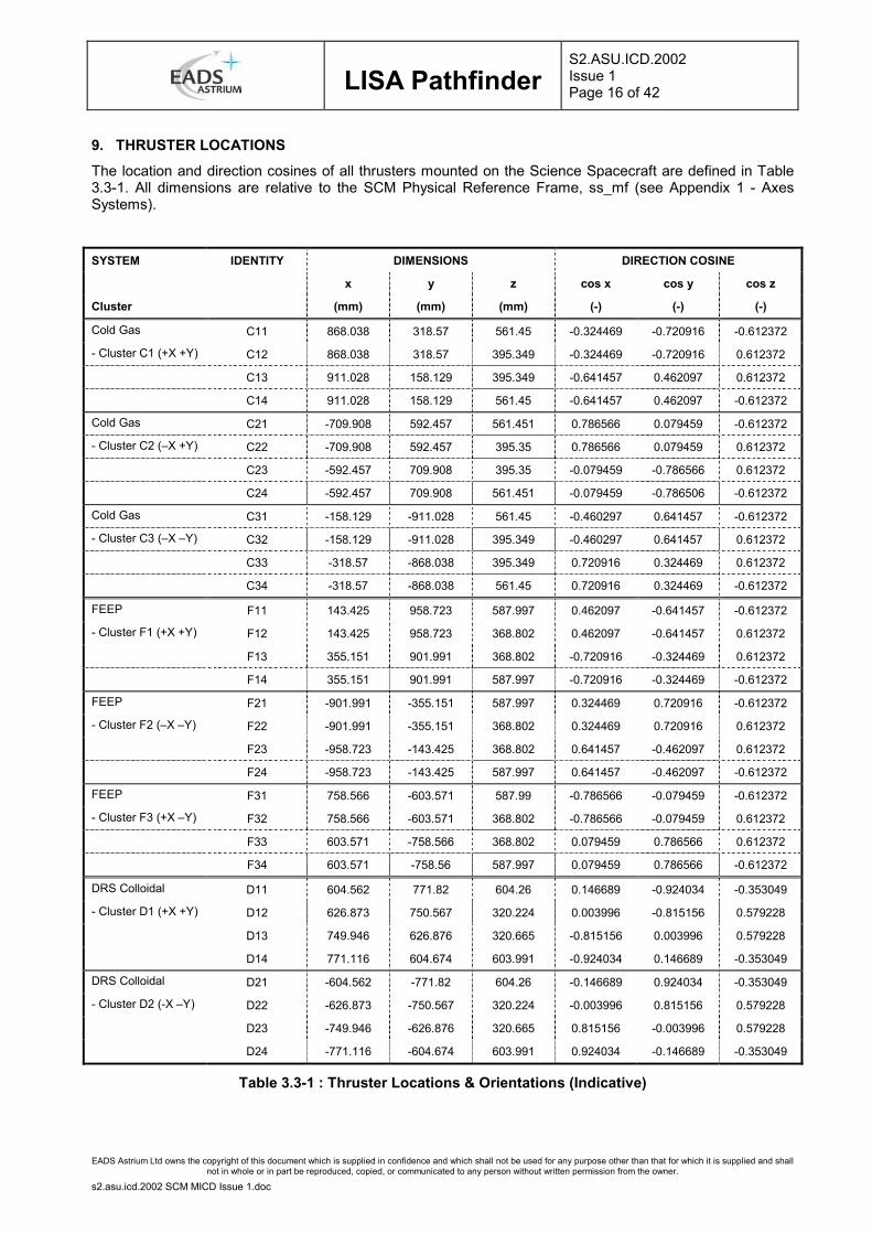
9. THRUSTER LOCATIONS The location and direction cosines of all thrusters mounted on the Science Spacecraft are defined in Table 3.3-1. All dimensions are relative to the SCM Physical Reference Frame, ss_mf (see Appendix 1 - Axes Systems).
SYSTEM IDENTITY DIMENSIONS DIRECTION COSINE
x y z cos x cos y cos z
Cluster (mm) (mm) (mm) (-) (-) (-)
Cold Gas C11 868.038 318.57 561.45 -0.324469 -0.720916 -0.612372
- Cluster C1 (+X +Y) C12 868.038 318.57 395.349 -0.324469 -0.720916 0.612372
C13 911.028 158.129 395.349 -0.641457 0.462097 0.612372
C14 911.028 158.129 561.45 -0.641457 0.462097 -0.612372
Cold Gas C21 -709.908 592.457 561.451 0.786566 0.079459 -0.612372
- Cluster C2 (–X +Y) C22 -709.908 592.457 395.35 0.786566 0.079459 0.612372
C23 -592.457 709.908 395.35 -0.079459 -0.786566 0.612372
C24 -592.457 709.908 561.451 -0.079459 -0.786506 -0.612372
Cold Gas C31 -158.129 -911.028 561.45 -0.460297 0.641457 -0.612372
- Cluster C3 (–X –Y) C32 -158.129 -911.028 395.349 -0.460297 0.641457 0.612372
C33 -318.57 -868.038 395.349 0.720916 0.324469 0.612372
C34 -318.57 -868.038 561.45 0.720916 0.324469 -0.612372
FEEP F11 143.425 958.723 587.997 0.462097 -0.641457 -0.612372
- Cluster F1 (+X +Y) F12 143.425 958.723 368.802 0.462097 -0.641457 0.612372
F13 355.151 901.991 368.802 -0.720916 -0.324469 0.612372
F14 355.151 901.991 587.997 -0.720916 -0.324469 -0.612372
FEEP F21 -901.991 -355.151 587.997 0.324469 0.720916 -0.612372
- Cluster F2 (–X –Y) F22 -901.991 -355.151 368.802 0.324469 0.720916 0.612372
F23 -958.723 -143.425 368.802 0.641457 -0.462097 0.612372
F24 -958.723 -143.425 587.997 0.641457 -0.462097 -0.612372
FEEP F31 758.566 -603.571 587.99 -0.786566 -0.079459 -0.612372
- Cluster F3 (+X –Y) F32 758.566 -603.571 368.802 -0.786566 -0.079459 0.612372
F33 603.571 -758.566 368.802 0.079459 0.786566 0.612372
F34 603.571 -758.56 587.997 0.079459 0.786566 -0.612372
DRS Colloidal D11 604.562 771.82 604.26 0.146689 -0.924034 -0.353049
- Cluster D1 (+X +Y) D12 626.873 750.567 320.224 0.003996 -0.815156 0.579228
D13 749.946 626.876 320.665 -0.815156 0.003996 0.579228
D14 771.116 604.674 603.991 -0.924034 0.146689 -0.353049
DRS Colloidal D21 -604.562 -771.82 604.26 -0.146689 0.924034 -0.353049
- Cluster D2 (-X –Y) D22 -626.873 -750.567 320.224 -0.003996 0.815156 0.579228
D23 -749.946 -626.876 320.665 0.815156 -0.003996 0.579228
D24 -771.116 -604.674 603.991 0.924034 -0.146689 -0.353049
Table 3.3-1 : Thruster Locations & Orientations (Indicative)

LISA Pathfinder
S2.ASU.ICD.2002 Issue 1 Page 17 of 42
EADS Astrium Ltd owns the copyright of this document which is supplied in confidence and which shall not be used for any purpose other than that for which it is supplied and shall not in whole or in part be reproduced, copied, or communicated to any person without written permission from the owner.
s2.asu.icd.2002 SCM MICD Issue 1.doc
10. EQUIPMENT BOLT DEFINITION The bolt sizes, numbers of holes and foot thickness for all equipments mounted on the Science Spacecraft are defined in Table 3.3-2.
EQUIPMENT NUMBER BOLT SIZE NUMBER FOOT
OF UNITS OF HOLES THICKNESS
Disturbance Reduction System
DRS – Sensor Assembly 1
– ASU : Thermal Shield 1 4 spools required for M5 bolts
– ASU : Main Struts 6 2 spools each required for M5 bolts
– Ion Gauge 2 M5 4 3.00 mm
– GCU 2 M5 6 3.00 mm
– Sensor Assembly Bulkhead 1 M5 4 5.00 mm
Note : Following additional inserts are to be provided in DRS Sensor Assembly Base Plate:- – three inserts are to be provided in the DRS Base Plate as lifting points for ground handling – four inserts are to be provided in the DRS Base Plate to accommodate alignment tooling balls.
DRS – Electronics Assembly 1
– Interferometer Laser (IFL) 1 M5 8 5.63 mm
– Interferometer Electronics (IFE) 1 M5 10 5.50 mm
– Integrated Avionics Unit (IAU) 1 M4 6 2.54 mm
– Ultra Violet Source (UVS) 1 M5 6 6.35 mm
– Electronics Assembly Bulkhead 1 M5 8 3.00 mm
Note : Following additional inserts are to be provided is DRS Electronics Assembly Shear Wall:- – three (TBC) inserts are to be provided in the DRS Shear Wall as lifting points for ground handling – four inserts are to be provided in the DRS Shear Wall to accommodate alignment tooling balls.
DRS – Thruster Assembly 2 M5 20 8.26 mm
– two inserts are to be provided in the Thruster Assembly to accommodate alignment tooling balls.
LISA Technology Package
– LTP Core Assembly - Isostatic Mounts 3 M8 TBD TBD
– Diagnostic & Data Management System (DDS) 1 M5 TBD TBD
– Ultra-Violet Lamp Assembly (UVLA) 1 M5 TBD TBD
– Front End Electronics – Sensor Actuating Unit 1 M5 TBD TBD
- Front End Electronics – Power Conditioning Unit (FEE PCU)
1 M5 TBD TBD
– Inertia Sensor Caging Control Unit (IS CCU) 1 M5 TBD TBD
– Phase Meter 1 M5 TBD TBD
– Laser Unit 1 M5 TBD TBD
Table 3.3-1 : Science Spacecraft Payload Bolt Definition (Indicative)

LISA Pathfinder
S2.ASU.ICD.2002 Issue 1 Page 18 of 42
EADS Astrium Ltd owns the copyright of this document which is supplied in confidence and which shall not be used for any purpose other than that for which it is supplied and shall not in whole or in part be reproduced, copied, or communicated to any person without written permission from the owner.
s2.asu.icd.2002 SCM MICD Issue 1.doc
EQUIPMENT NUMBER BOLT SIZE NUMBER FOOT
OF UNITS OF HOLES THICKNESS
Attitude & Orbit Control Subsystem
– Star Tracker Head * 2 TBD TBD TBD
– Star Tracker Electronics 2 TBD TBD TBD
– Digital Sun Sensor 3 TBD TBD TBD
– Rate Measurement Unit * 3 assys TBD TBD TBD
Cold Gas MicroPropulsion System
– Thruster Cluster 3 TBD TBD TBD
– Closed Loop Control Electronics (CLCE) 3 TBD TBD TBD
– Proportional Electronic Pressure Regulator Electronics (PEPRE)
1 TBD TBD TBD
– Feed Assembly (inc. PEPR) 1 TBD TBD TBD
– Pressurant Tank Mounting Bearing Assembly 4 TBD TBD TBD
Data Handling Subsystem
– On Board Computer 1 TBD TBD TBD
FEEP MicroPropulsion System – Thruster Cluster 3 TBD TBD TBD
– PCU 3 TBD TBD TBD
– FEEP Diagnostic Package 1 TBD TBD TBD
FEEP Diagnostic Package – Plasma Probe Assembly 1 TBD TBD TBD
– Micro Balance Assembly 1 TBD TBD TBD
– Solar Cell Assembly 1 TBD TBD TBD
– Interface Electronics Assembly 1 TBD TBD TBD
Power Subsystem – Solar Array 1 TBD TBD TBD
– Power Conditioning & Distribution Unit (PCDU) 1 TBD TBD TBD
– Battery 1 TBD TBD TBD
TT & C Subsystem – Medium Gain Antenna (MGA) * 1 TBD TBD TBD
– Low Gain Antenna (LGA) * 2 TBD TBD TBD
– Diplexer 3 TBD TBD TBD
– Solid State Power Amplifier (SSPA) 2 TBD TBD TBD
– Transponder 2 TBD TBD TBD
Structure Subsystem Mounting Brackets
– Star Tracker Head Mounting Bracket 1 TBD TBD TBD
– RMU Mounting Bracket 1 TBD TBD TBD
– Pressurant Tank Mounting Bracket 2 TBD TBD TBD
– MGA Mounting Bracket 1 TBD TBD TBD
– LGA Mounting Bracket 2 TBD TBD TBD
* requires mounting bracket
Table 3.3-2 : Science Spacecraft Equipment Bolt Definition

LISA Pathfinder
S2.ASU.ICD.2002 Issue 1 Page 19 of 42
EADS Astrium Ltd owns the copyright of this document which is supplied in confidence and which shall not be used for any purpose other than that for which it is supplied and shall not in whole or in part be reproduced, copied, or communicated to any person without written permission from the owner.
s2.asu.icd.2002 SCM MICD Issue 1.doc
11. APPENDICES
11.1 Appendix 1 - Axes Systems

LISA Pathfinder
S2.ASU.ICD.2002 Issue 1 Page 20 of 42
Table 11.1-1 : SCM Axes Systems
s2.asu.icd.2002 SCM MICD Issue 1.doc

LISA Pathfinder
S2.ASU.ICD.2002 Issue 1 Page 21 of 42
Table 11.1-2 : DRS & LTP Axes Systems
EADS Astrium Ltd owns the copyright of this document which is supplied in confidence and which shall not be used for any purpose other than that for which it is supplied and shall not in whole or in part be reproduced, copied, or communicated to any person without written permission from the owner.
s2.asu.icd.2002 SCM MICD Issue 1.doc

LISA Pathfinder
S2.ASU.ICD.2002 Issue 1 Page 22 of 42
Table 11.1-3 : Star Tracker Axes Systems
EADS Astrium Ltd owns the copyright of this document which is supplied in confidence and which shall not be used for any purpose other than that for which it is supplied and shall not in whole or in part be reproduced, copied, or communicated to any person without written permission from the owner.
s2.asu.icd.2002 SCM MICD Issue 1.doc

LISA Pathfinder
S2.ASU.ICD.2002 Issue 1 Page 23 of 42
Table 11.1-4 : Digital Sun Sensors Axes Systems
EADS Astrium Ltd owns the copyright of this document which is supplied in confidence and which shall not be used for any purpose other than that for which it is supplied and shall not in whole or in part be reproduced, copied, or communicated to any person without written permission from the owner.
s2.asu.icd.2002 SCM MICD Issue 1.doc

LISA Pathfinder
S2.ASU.ICD.2002 Issue 1 Page 24 of 42
Table 11.1-5 : Rate Measurement Unit Axes Systems
EADS Astrium Ltd owns the copyright of this document which is supplied in confidence and which shall not be used for any purpose other than that for which it is supplied and shall not in whole or in part be reproduced, copied, or communicated to any person without written permission from the owner.
s2.asu.icd.2002 SCM MICD Issue 1.doc

LISA Pathfinder
S2.ASU.ICD.2002 Issue 1 Page 25 of 42
11.2 Appendix 2 – Science Spacecraft Interface Requirement Drawings The drawing status is summarised in Table 3.3-1.
s2.asu.icd.2002 SCM MICD Issue 1.doc

LISA Pathfinder
S2.ASU.ICD.2002 Issue 1 Page 26 of 42
EADS Astrium Ltd owns the copyright of this document which is supplied in confidence and which shall not be used for any purpose other than that for which it is supplied and shall not in whole or in part be reproduced, copied, or communicated to any person without written permission from the owner.
s2.asu.icd.2002 SCM MICD Issue 1.doc

LISA Pathfinder
S2.ASU.ICD.2002 Issue 1 Page 27 of 42
EADS Astrium Ltd owns the copyright of this document which is supplied in confidence and which shall not be used for any purpose other than that for which it is supplied and shall not in whole or in part be reproduced, copied, or communicated to any person without written permission from the owner.
s2.asu.icd.2002 SCM MICD Issue 1.doc

LISA Pathfinder
S2.ASU.ICD.2002 Issue 1 Page 28 of 42
EADS Astrium Ltd owns the copyright of this document which is supplied in confidence and which shall not be used for any purpose other than that for which it is supplied and shall not in whole or in part be reproduced, copied, or communicated to any person without written permission from the owner.
s2.asu.icd.2002 SCM MICD Issue 1.doc

LISA Pathfinder
S2.ASU.ICD.2002 Issue 1 Page 29 of 42
EADS Astrium Ltd owns the copyright of this document which is supplied in confidence and which shall not be used for any purpose other than that for which it is supplied and shall not in whole or in part be reproduced, copied, or communicated to any person without written permission from the owner.
s2.asu.icd.2002 SCM MICD Issue 1.doc

LISA Pathfinder
S2.ASU.ICD.2002 Issue 1 Page 30 of 42
11.3 Appendix 3 – Science Spacecraft Configuration Drawings The drawing status is summarised in Table 3.3-1.
EADS Astrium Ltd owns the copyright of this document which is supplied in confidence and which shall not be used for any purpose other than that for which it is supplied and shall not in whole or in part be reproduced, copied, or communicated to any person without written permission from the owner.
s2.asu.icd.2002 SCM MICD Issue 1.doc

LISA Pathfinder
S2.ASU.ICD.2002 Issue 1 Page 31 of 42
EADS Astrium Ltd owns the copyright of this document which is supplied in confidence and which shall not be used for any purpose other than that for which it is supplied and shall not in whole or in part be reproduced, copied, or communicated to any person without written permission from the owner.
s2.asu.icd.2002 SCM MICD Issue 1.doc

LISA Pathfinder
S2.ASU.ICD.2002 Issue 1 Page 32 of 42
EADS Astrium Ltd owns the copyright of this document which is supplied in confidence and which shall not be used for any purpose other than that for which it is supplied and shall not in whole or in part be reproduced, copied, or communicated to any person without written permission from the owner.
s2.asu.icd.2002 SCM MICD Issue 1.doc

LISA Pathfinder
S2.ASU.ICD.2002 Issue 1 Page 33 of 42
EADS Astrium Ltd owns the copyright of this document which is supplied in confidence and which shall not be used for any purpose other than that for which it is supplied and shall not in whole or in part be reproduced, copied, or communicated to any person without written permission from the owner.
s2.asu.icd.2002 SCM MICD Issue 1.doc

LISA Pathfinder
S2.ASU.ICD.2002 Issue 1 Page 34 of 42
EADS Astrium Ltd owns the copyright of this document which is supplied in confidence and which shall not be used for any purpose other than that for which it is supplied and shall not in whole or in part be reproduced, copied, or communicated to any person without written permission from the owner.
s2.asu.icd.2002 SCM MICD Issue 1.doc

LISA Pathfinder
S2.ASU.ICD.2002 Issue 1 Page 35 of 42
EADS Astrium Ltd owns the copyright of this document which is supplied in confidence and which shall not be used for any purpose other than that for which it is supplied and shall not in whole or in part be reproduced, copied, or communicated to any person without written permission from the owner.
s2.asu.icd.2002 SCM MICD Issue 1.doc

LISA Pathfinder
S2.ASU.ICD.2002 Issue 1 Page 36 of 42
EADS Astrium Ltd owns the copyright of this document which is supplied in confidence and which shall not be used for any purpose other than that for which it is supplied and shall not in whole or in part be reproduced, copied, or communicated to any person without written permission from the owner.
s2.asu.icd.2002 SCM MICD Issue 1.doc

LISA Pathfinder
S2.ASU.ICD.2002 Issue 1 Page 37 of 42
EADS Astrium Ltd owns the copyright of this document which is supplied in confidence and which shall not be used for any purpose other than that for which it is supplied and shall not in whole or in part be reproduced, copied, or communicated to any person without written permission from the owner.
s2.asu.icd.2002 SCM MICD Issue 1.doc

LISA Pathfinder
S2.ASU.ICD.2002 Issue 1 Page 38 of 42
EADS Astrium Ltd owns the copyright of this document which is supplied in confidence and which shall not be used for any purpose other than that for which it is supplied and shall not in whole or in part be reproduced, copied, or communicated to any person without written permission from the owner.
s2.asu.icd.2002 SCM MICD Issue 1.doc

LISA Pathfinder
S2.ASU.ICD.2002 Issue 1 Page 39 of 42
EADS Astrium Ltd owns the copyright of this document which is supplied in confidence and which shall not be used for any purpose other than that for which it is supplied and shall not in whole or in part be reproduced, copied, or communicated to any person without written permission from the owner.
s2.asu.icd.2002 SCM MICD Issue 1.doc

LISA Pathfinder
S2.ASU.ICD.2002 Issue 1 Page 40 of 42
EADS Astrium Ltd owns the copyright of this document which is supplied in confidence and which shall not be used for any purpose other than that for which it is supplied and shall not in whole or in part be reproduced, copied, or communicated to any person without written permission from the owner.
s2.asu.icd.2002 SCM MICD Issue 1.doc

LISA Pathfinder
S2.ASU.ICD.2002 Issue 1 Page 41 of 42
EADS Astrium Ltd owns the copyright of this document which is supplied in confidence and which shall not be used for any purpose other than that for which it is supplied and shall not in whole or in part be reproduced, copied, or communicated to any person without written permission from the owner.
s2.asu.icd.2002 SCM MICD Issue 1.doc
INTENTIONALLY BLANK

LISA Pathfinder
S2.ASU.ICD.2002 Issue 1 Page 42 of 42
EADS Astrium Ltd owns the copyright of this document which is supplied in confidence and which shall not be used for any purpose other than that for which it is supplied and shall not in whole or in part be reproduced, copied, or communicated to any person without written permission from the owner.
s2.asu.icd.2002 SCM MICD Issue 1.doc
DOCUMENT CHANGE DETAILS
ISSUE CHANGE AUTHORITY CLASS RELEVANT INFORMATION/INSTRUCTIONS
A - - Initial Issue For Draft SCM Structure ITT
1 - - Formal Issue For SCM Structure ITT
DISTRIBUTION LIST
INTERNAL EXTERNAL
S. Barraclough A. G. Jones LISA Pathfinder Project Office, ESA P. Chapman M. Kemp LTP Project Office , EADS Astrium GmbH, FHN M. Davidson P. Kemp DRS Project Office, JPL, USA N. Dunbar M. Sprague A. Elliott M. Stewart R. Fayard K. Tomkins K. Gould G. Viney R. Gray D. Wealthy D. Head Configuration Management


