
(Science for Adults) VACUUM ENGINE Vacuum...
14
VACUUM ENGINE Vacuum Engine Otona no Kagaku (Science for Adults) Product Version Instructions for Assembly and Operating
Transcript of (Science for Adults) VACUUM ENGINE Vacuum...

VACUUM ENGINE Vacuum EngineOtona no Kagaku
(Science for Adults)Product Version
Instructions for Assembly and Operating

FPARTS FPARTS
GPARTS GPARTS
CAUTION: The kit may contain more screws, etc. than actually required, for use as spares.
* Do not confuse the 4 washer head screw with the 5 washer head tapping screw. They are different.
* NOTE: The actual shapes of some parts may differ from the illustrations above.
PARTS A
B
C
D
A1 A2 A4
A3
A5
A6A7
A8
A10A9
TOOL&PARTSTOOL&PARTS
E1
E2
E3
E4
E5
PARTSB1 B2 B3
B4
PARTSC1
C2 C4C3
C5
PARTS
PARTS A
B
C
D
PARTS
PARTS
PARTS
F1
18
9
10
F2
F5
F3 F4
2 3
5
6
74
E1 E1
E2 E2
E1
E2
G1 G2
G3G4
PARTS H PARTS H
D1
D2
D3 D3 D4 D4D5D5
D6
11 12
H1H2
H3
H2
H3
H2
H3
H2
H3
PARTS E
F5
PARTS E
Parts List Vacuum Engine
A1: CylinderA2: FlywheelA3: Crank unit (top)A4: Crank unit (bottom)A5: Piston unitA6: Valve rodA7: Cooling fanA8: ValveA9: Valve rod stopperA10: Fan belt
B1: Car bodyB2: Drive gearB3: Bearing guideB4: Bearing (5)
C1: Steering wheelC2: Steering gearC3: Worm gearC4: Steering-wheel holderC5: Universal joint
D1: Upper armD2: Tie-rodD3: King pins (2)D4: Springs (2)D5: Center shafts (2)D6: Worm gear cove
E1: Wheels (4)E2: Tires (4)E3: Rear shaftE4: Clutch wheelE5: O-ring
F1: Clutch boxF2: Clutch leverF3: Clutch guideF4: SeatF5: Shaft stoppers (2)
G1: Fuel tank attachment part AG2: Fuel tank attachment part BG3: Fuel tank (2)G4: Wick
H1: StandH2: Car body holders (4)H3: Non-slip pads (4)
1: Screw2: Screw (short) (1)3: Screw (long) (3)4: Washer head screw (5)5: Washer head tapping screw (3)6: Hex nut (2)7: Nut (small) (1)8: Sticker9: Screwdriver (Phillips)10: Pipet11: Wrench12: Hex wrench
32

Turn
Before Assembling the Kit1. How to use the supplied tools
4. Difference between the washer head screw and the washer head tapping screw
2. How to use the hex wrench
3. How to use the wrench
5. Small parts
●Phillips screwdriver
The screwdriver is used for fastening screws, etc.
●Hex wrench
The hex wrench is used for installing the flywheel.
When turned, the washer head tapping screw for plastic cuts its own threads as it is driven into the material. The washer head tapping screw has a coarser thread pitch than the washer head screw.
The kit contains many small parts. Be careful so as not to lose them.We recommend that you turn the stand over and use it as a tray for holding the small parts.
How to use the Phillips screwdriver
How to use the wrench
Difference between the washer head screw and the washer head tapping screw
Turn
Washer head screw Washer head
* In addition to the parts and tools supplied, have on hand alcohol fuel, a pair of scissors, a towel, tissues, and aluminum foil. Alcohol fuel can be purchased at drugstores.
Finer thread pitch
Coarser thread pitch
● Wrench
The wrench is used for tightening nuts.
How to use the hex wrench
Turn
54
CAUTION: Please read the following instructions before using this kit.
Use this kit only for its intended purpose.Fire is used in the experiment. Exercise extreme care to avoid burning yourself or starting a fire.Never touch the cylinder while the engine is running. There is a risk of burning.The cylinder will remain hot for a while after you have completed the experiment. Do not touch the cylinder. There is a risk of burning. When touching it, do so after making sure that it has cooled sufficiently.Take necessary caution when handling any metallic parts. There is a risk of injury.There are small parts such as screws. Be careful not to swallow them. There is a risk of suffocation.Take caution not to pork your hands or eyes, with the supplied screwdriver and the like. There is a risk of injury.Do not operate the machine on the road. There is a risk of traffic accident.
* Please read the assembly and operating instructions and cautions in this manual thoroughly before attempting to assemble this kit. In addition, do not use any parts that have become damaged or deformed during use.* Store the kit in a location out of the reach of small children.
Plastic materials used in this kit • Drive gear, steering gear (black): POM Seat, steering wheel, clutch lever (brown): PS Screwdriver handle (orange): Polyethylene Small bags (transparent and colorless): Polyethylene
Metallic materials used in this kit •Car body, stand, and other body parts: Aluminum Shaft: Iron Valve: Brass Screws, etc.: Iron (nickel plated)* Please dispose of this product in accordance with local regulations.
CAUTION: Fire is used in the experiment. Exercise extreme care to avoid burning yourself or starting a fire. Do not allow children 15 years of age or younger to conduct the experiment without adult supervision.

* The kit may contain more screws, etc. than actually required, for use as spares.
1 Assembling the Engine
A1: Cylinder A5 : Piston unit
A9 : Valve rod stopper
A6 : Valve rod A7 : Cooling fan
A2 : Flywheel A3 Crank unit (top) A4 Crank unit (bottom)
A8 : Valve
(1) Install the valve rod.Figure-(1)Set the A6 valve rod in the A1 cylinder, and install the A9 valve rod stopper using a screw.
(4) Install the valve.
(3) Install the cylinder in the crank unit.Figure-(3)Install the assembled A1 cylinder in the A4 crank unit (bottom).At this point, fit the A6 valve rod into the groove on the A4 crank unit (bottom).At the same time, insert the pin of the A4 crank unit (bottom) into the A5 piston unit.Finally, use the screws to secure the A5 piston unit from the bottom side.
CAUTION: Fire is used in the experiment. Exercise extreme care to avoid burning yourself or starting a fire. Do not allow children 15 years of age or younger to conduct the experiment without adult supervision.
A10 : Fan belt
(2) Insert the piston unit into the cylinder.
A1: Cylinder
A5: Piston unit
Screw (long)
Screws (6)
Figure-(4)Insert the A8 valve into the space between the A1 cylinder and the A6 valve.At this point, slightly lifting the arm part of the A6 valve rod will make insertion easier.
ScrewA9: Valve rod stopper
A6: Valve rod
A1: Cylinder
A6: Valve rod
A1: Cylinder
A8: ValveLift the arm slightly when inserting the A8 valve.
A6: Valve rod
A1: Cylinder
A5: Piston unit
A4: Crank unit (bottom)
ScrewScrew
Arm
Connecting the valve rod to the crank unit (bottom)
A6: Valve rod
A4: Crank unit (bottom)
A1: CylinderA5: Piston unit
Before assembly, use a tissue impregnated with alcohol fuel to wipe clean the inside of the cylinder and the piston unit.
Figure-(2)Insert the A5 piston unit into the A1 cylinder. (If the A1 cylinder or the A5 piston unit is contaminated with grease, use alcohol fuel to wipe it clean.)
At this point, make sure that the piston unit can be turned smoothly by hand in the clockwise
There is a very slight gap (approx. 0.1 mm) between the front face of the cylinder and the valve.
Side view
PARTS AParts to be used
A1: Cylinder
A8: Valve
Arm
A6: Valve rod
View showing the piston unit connected to the crank unit (bottom)
View showing the valve rod connected to the crank unit (bottom)
CAUTION
76

Screw
Screw
Screw
* The kit may contain more screws, etc. than actually required, for use as spares.
2 Installing the Drive Gear in the Car Body
B1: Car body B2: Drive gear B3: Bearing guide B4: Bearings (4)
Washer head tapping screw (1)
(5) Install the crank unit.Figure-(5)Using three screws, install the A3 crank unit (top) onto the crank unit (bottom) assembled in Figure-(4).For this step, connect the A3 crank unit (top) to the pins of the A4 crank unit as shown in the figure. (The result is shown in the figure below.)
(6) Install the flywheel.
Figure-(6)Using the hex wrench, turn the flywheel installation screw and install the flywheel.
(7) Install the cooling fan.Figure-(7)Use the screw (long) to secure the A7 cooling fan to the A1 cylinder.Then, use the A10 fan belt to connect the A7 cooling fan to the A2 flywheel.
(8) Install the bearing guide with bearings in the drive gear.
Figure-(8)Place the B3 bearing guide on the B2 drive gear and set all four B4 bearings in the B3 bearing guide.
(9) Install the drive gear with bearings onto the car body.
Figure-(9)Use the washer head tapping screw to secure the drive gear assembled in Figure-(8) to the car body.During this step, be careful not to lose the bearings.
CAUTION: Fire is used in the experiment. Exercise extreme care to avoid burning yourself or starting a fire. Do not allow children 1 years of age or younger to conduct the experiment without adult supervision.
A5: Piston unit
A5: Piston unit
Pin of the A4 crank unit (bottom)
Crank unit (bottom)
Cross sectional diagram of the connection area
The drive gear assembled in Figure-(8)
B3: Bearing guide
B4: Bearings
B4: Bearings
B2: Drive gear
Washer head tapping screw
B1: Car body
A3: Crank unit (top)
A3: Crank unit (top)
Be sure to use the screw with the coarser thread pitch.
Crank Unit A4 (bottom) assembled in Figure-(4)
A6: Valve rod
A1: Cylinder
Flywheel installation screw (already embedded)
A2: Flywheel
Make sure that the A2 flywheel can be turned smoothly by hand in the clockwise direction viewed from above.
It is best if the piston falls gently when the crank unit is held in the orientation shown above.
* Keep one as a spare.
Screw (long)
A8: Valve
A1: Cylinder
A7: Cooling fan
A10: Fan belt
A2: Flywheel
Piston
Hex wrench
Circular platter
Insert into the hole.
Place the tip of the screw against this flat surface.
Push up the circular platter of the crank and then insert the pin.
The flywheel installation screw is already embedded.
PARTS BParts to be used
CAUTION
98

4 Assembling the Suspension
(10) Install the steering-wheel holder.Figure-(10)Insert the C4 steering-wheel holder into the slits in the B1 car body, and secure it with the screw.
(11) Install the steering wheel.
Figure-(11)Pass the C1 steering wheel through the C4 steering-wheel holder.Next, set the C3 worm gear in the B1 car body.Lastly, use the C5 universal joint to link the C1 steering wheel to the C3 worm gear.
(12) Install the steering gear.Figure-(12)Using the washer head screw (with the finer thread pitch), install the C2 steering gear in the B1 car body.
(13) Assemble the tie-rod.Figure-(13)Using the washer head screws, secure the D3 king pins to the D2 tie-rod in two locations.
C4: Steering-wheel holder
Screw
B1: Car body
B1: Car body
B1: Car body
* Insert the holder into the slits in the B1 car body.
C1: Steering wheel C5: Universal joint
C3: Worm gear
C4: Steering-wheel holder
C2: Steering gear
C3: Worm gear
C5: Universal joint
C1: Steering wheel
C4: Steering-wheel holder
D1 : Upper arm
D4 : Springs (2) D5 : Center shafts (2) D6 : Worm gear cover Screws (2) Washer head screws (2)
Washer head tapping screw (1)
D3 : King pins (2)D2 : Tie-rod
D2: Tie-rod
D3: King pins
* The kit may contain more screws, etc. than actually required, for use as spares.
3 Installing the Steering Wheel in the Car Body
C1 : Steering wheel C2 : Steering gear C3 : Worm gear C4 : Steering-wheel holder
C5: Universal joint
Washer head screw (1)
Screw (1)
* The kit may contain more screws, etc. than actually required, for use as spares. Washer head screw
(with the finer thread pitch)
Washer head screw (with the finer thread pitch)
Washer head screw (with the finer thread pitch)
PARTS CParts to be used
Cross-sectional diagram showing how the
steering wheel is set
* Put the C3 worm gear through this area in the B1 car body, and use the C5 universal joint to link it to the C1 steering wheel.
CAUTION: Fire is used in the experiment. Exercise extreme care to avoid burning yourself or starting a fire. Do not allow children 15 years of age or younger to conduct the experiment without adult supervision.
PARTS DParts to be used
1110
* The kit may contain more screws, etc. than actually required, for use as spares
5 Assembling the Wheels
E1 : Wheels (4) E3 : Rear shaft
E4 : Clutch wheel
E2 : Tires (4)
サスペンションの断面
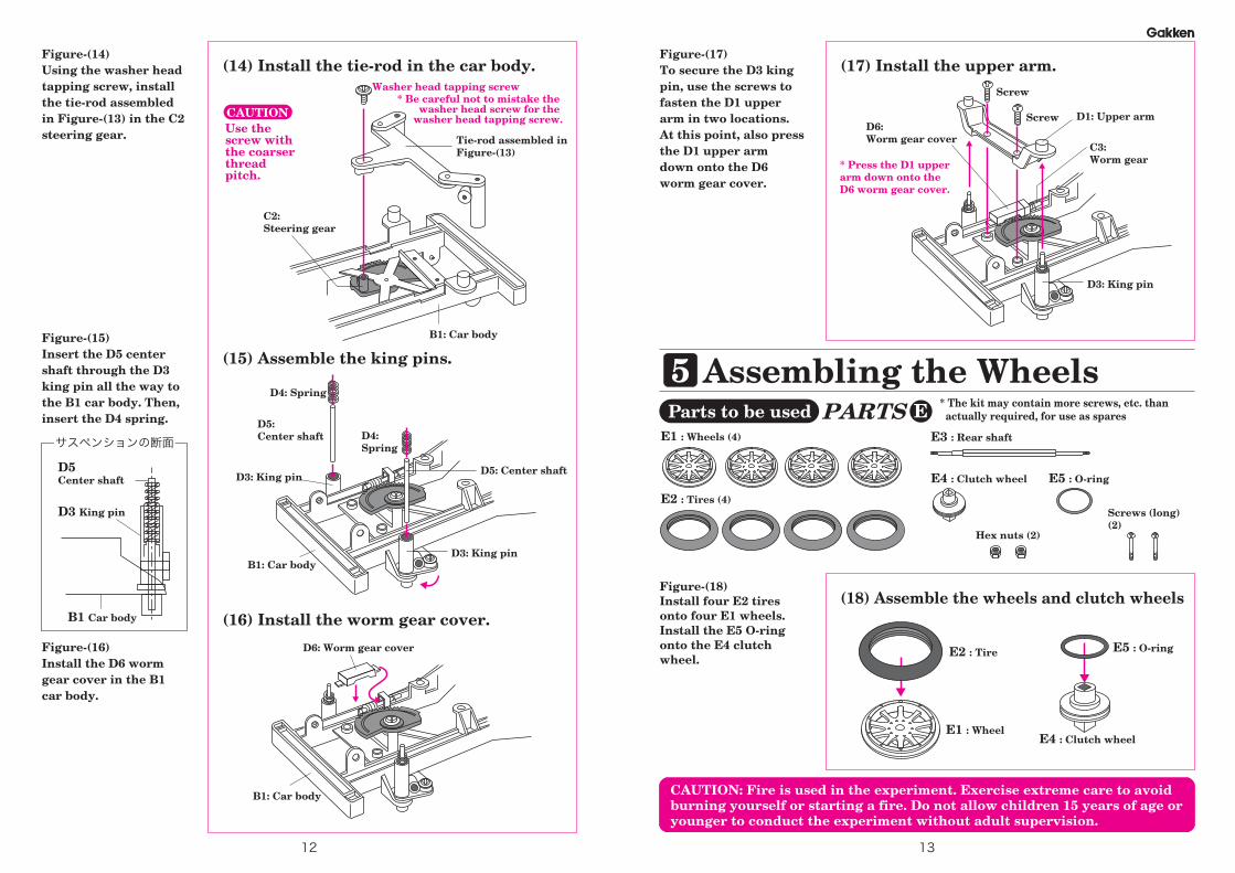
(15) Assemble the king pins.Figure-(15)Insert the D5 center shaft through the D3 king pin all the way to the B1 car body. Then, insert the D4 spring.
(16) Install the worm gear cover.
Figure-(16)Install the D6 worm gear cover in the B1 car body.
(17) Install the upper arm.Figure-(17)To secure the D3 king pin, use the screws to fasten the D1 upper arm in two locations. At this point, also press the D1 upper arm down onto the D6 worm gear cover.
D4: Spring
D4: Spring
D5: Center shaft
D5: Center shaft
B1: Car body
B1: Car body
D3: King pin
D3: King pin
D3: King pin
Screw
Screw
D1: Upper arm
C3: Worm gear
D6: Worm gear cover
D3 King pin
B1 Car body
Hex nuts (2)
Screws (long) (2)
D5Center shaft E5 : O-ring
(18) Assemble the wheels and clutch wheels
E4 : Clutch wheel
E2 : Tire
E1 : Wheel
E5 : O-ring
Figure-(18)Install four E2 tires onto four E1 wheels. Install the E5 O-ring onto the E4 clutch wheel.
(14) Install the tie-rod in the car body.Figure-(14)Using the washer head tapping screw, install the tie-rod assembled in Figure-(13) in the C2 steering gear. Tie-rod assembled in
Figure-(13)
B1: Car body
C2: Steering gear
* Be careful not to mistake the washer head screw for the
washer head tapping screw.
D6: Worm gear cover
Use the screw with the coarser thread pitch.
CAUTION
Washer head tapping screw
* Press the D1 upper arm down onto the D6 worm gear cover.
PARTS EParts to be used
CAUTION: Fire is used in the experiment. Exercise extreme care to avoid burning yourself or starting a fire. Do not allow children 15 years of age or younger to conduct the experiment without adult supervision.
1312

* The kit may contain more screws, etc. than actually required, for use as spares.
6 Assembling the Clutch and Installing the Rear Wheels
(21) Install the clutch box and seat.Figure-(21)Set the F2 clutch lever in the F1 clutch box, and use a screw to install them in the B1 car body.Then, use a washer head tapping screw to install the F4 seat as well.
F1 : Clutch box F2 : Clutch lever F3 : Clutch guide F4 : Seat
Screws (3)
(22) Install the clutch guide.
Figure-(22)From the bottom side of the B1 car body, thread the F3 clutch guide to the tip of the F2 clutch lever.Then, use a washer head screw (with the finer thread pitch) to install the clutch guide. (Be careful not to insert the screw in the wrong hole.)
B1: Car body
Screw
F4: Seat
F2: Clutch lever
F1: Clutch box
Cross sectional diagram of the set clutch
F2: Clutch lever
F3: Clutch guide
F3: Clutch guide
(20) Assemble the rear wheels.
Figure-(20)Install the hex nut, a wheel, the E4 clutch wheel, another wheel, and the hex nut, in that order onto the E3 rear shaft.
Wheel assembled in Figure-(18)
Wheel assembled in Figure-(18)
E4: Clutch wheel
(19) Install the front wheels onto the car body.Figure-(19)Using the screws (long), install the two wheels assembled in Figure-(18) onto the D3 king pins.
Wheel assembled in Figure-(18)
Wheel assembled in Figure-(18)
Screw (long)
Screw (long)
D3: King pin
Cross sectional diagram of the car body and wheel
How to use the wrench
B1: Car body
Screw (long)
B1: Car body
D3: King pin
Hex nut
Hex nutE3: Rear shaft
Make sure that turning the steering wheel also turns the front wheels.
Steering gear
Steering wheel
Turn
F5 : Shaft stoppers (2)
Washer head screw (1)
B1: Car body
F1: Clutch abox
F2: Clutch lever
B1: Car body
Rotate the pin of the clutch lever so that it engages with the clutch box.
Wheel assembled in Figure-(18)
This side becomes fixed. (When the engine is started while the car is placed on the stand, only this side turns.)
PARTS FParts to be used
Cross sectional diagram of the car body and the clutch
Washer head screw (with a finer thread pitch)
CAUTION: Fire is used in the experiment. Exercise extreme care to avoid burning yourself or starting a fire. Do not allow children 15 years of age or younger to conduct the experiment without adult supervision.
1514

(25) Assemble the fuel tank.
Fuel tank assembled in Figure-(24)
(23) Install the rear wheels onto the car body.
* The kit may contain more screws, etc. than actually required, for use as spares.
7 Installing the Fuel Tank
(24) Make the wick.Figure-(24)Cut the aluminum foil into a sheet measuring 5 cm × 6 to 7 cm.Wrap the cut aluminum foil onto the wick.
G1 G3 : Fuel tank G4 Wick
Screw (1)
Screw (small) (1)
Nut (small) (1)
Screw
Screw
E3: Rear shaft
F5: Shaft stopper
F5: Shaft stopper
Figure-(23)Use the F5 shaft stoppers and screws to fasten the rear wheels assembled in Figure-(20) in two locations.CAUTION: The rear wheels cannot be installed if their left-right orientation is wrong.
: Fuel tank attachment part A
G2 : Fuel tank attachment part B
Front
Rear
B1: Car body
Cross sectional diagram of the set clutch
E4: Clutch wheelF3: Clutch guide
How to cut the G4 wick
54 6(cm)
3210
Cut the G4 wick to 6 cm.
* Keep the remainder as a spare.
G4: Wick
8 Installing the Engine(26) Install the engine.
Figure-(26)Using the four screws, install the engine assembled in Figure-(7) in the B1 car body.
Engine assembled in Figure-(7)
B1: Car body
ScrewsScrews
* The kit may contain more screws, etc. than actually required, for use as spares.
Screws (4)
Wide
Figure-(25)Set the G3 fuel tank and the wick made in Figure-(24) in the G1 fuel tank attachment part A, and use the screw (small) and the nut (small) to secure the G2 fuel tank attachment part B.Then, use the screw to install the fuel tank in front of the front wheels.
Thin
Thick
Difference in the rear shaft thickness
Front
Rear
Set the clutch wheel at the center of the clutch guide.
5cm
6 to 7 cm
Wrap it onto the G4 wick.
Aluminum foilAluminum foil
Finished wick
Screw
B1: Car body
G4: Wick
G2: Fuel tank attachment part B
G3: Fuel tank
G1: Fuel tank attachment part A
Nut (small)
Screw (small)
3mm
Expose about 3 mm at the tip.
5mm
Aluminum foil
5cm
Narrow
PARTS GParts to be used
Use these values as guidelines for exposing the wick. Make adjustments as needed.
Parts to be used
CAUTION: Fire is used in the experiment. Exercise extreme care to avoid burning yourself or starting a fire. Do not allow children 15 years of age or younger to conduct the experiment without adult supervision.
* Keep the extra as a spare.
1716

(30) How to inject alcohol fuel.Figure-(30)Inject the alcohol fuel into the fuel tank. (The amount that can be drawn up into the supplied pipet is about right.) Be careful not to spill any alcohol fuel when injecting it into the fuel tank. Should a spill occur, use a tissue and the like to wipe it up completely. Then, wet the tissue with water before discarding it.* Alcohol fuel can be purchased at drugstores and the like.
Wet towel
Pipet
Fuel tank
(28) Set the car body on the stand to complete.
Figure-(28)Set the assembled car body on the stand.Apply the sticker to the desired location.
(29) Check the rotation of the flywheel.Figure-(29)Make sure that the flywheel can be turned smoothly by hand in the clockwise direction viewed from above.If it resists turning, check the assembly again.It is normal for the flywheel to resist turning when turned in the opposite direction (in the counter-clockwise direction viewed from above).
10 Experiment on Starting the Engine
Sticker
A2: Flywheel
* Turns in the clockwise direction.
* The kit may contain more screws, etc. than actually required, for use as spares.
9 Assembling the Stand
(27) Install the car body holders in the stand.
H1 : Stand H2 : Car body holders (4) H3 : Non-slip pads (4))
Screws (4)
Screw
ScrewScrew
Screw
H3: Non-slip pad
H3: Non-slip pad
H3: Non-slip pad
H3: Non-slip pad
H2: Car body holder H2: Car body holder
H1: Stand
Push the pad into the cutout area.
H3: Non-slip pad
Figure-(27)Using the screws, install the H2 car body holders onto the H1 stand, being careful about the correct orientation. Then, attach the H3 non-slip pads to the four locations on the bottom of the H1 stand.
* Pay attention to the orientation.
* Pay attention to the orientation.
Appropriate amount
Narrower gap for the front
Wider gap for the rear
PARTS HParts to be used
Peel off the protective film from the double-sided stickers and attach the pads
Protective film of the double-sided sticker
The A2 flywheel is embossed with an arrow indicating the correct turning direction.
Since this experiment involves the use of a flame, have a wet towel, etc. readily available for emergency use.
CAUTION: Fire is used in the experiment. Exercise extreme care to avoid burning yourself or starting a fire. Have a wet towel, etc. readily available for emergency use.
Fill to this line
1918

(31) Make sure that the gear lever is in the neutral position.
Figure-(31)Make sure that the gear lever is in the neutral position. (The gear lever is nearly vertical when in the neutral position.)If the gear lever is not in the neutral position, that is, if the gear is engaged, it will be difficult to start the engine.
(32) Light the wick and start the engine by manually turning the flywheel.
Figure-(32)Light the wick and start the engine by manually turning the flywheel in the clockwise direction viewed from above.
(33) Experiment to turn the left rear wheel.
Figure-(33)When the rotational speed has increased, move the gear lever forward or backward and check the rotational direction of the left rear wheel.You can shift the gear between forward and backward, and also see continuous changes in the rotational speed.
CAUTION: The experiment for rotating the rear wheel must be done while the car is mounted on the stand. While the experiment is underway, do not remove the car from the stand or turn the car upside down. Doing so will cause the alcohol fuel to spill, resulting in a fire hazard.Furthermore, if the overall color of the flame becomes orange, this indicates that the alcohol fuel is running out and the cotton wick is beginning to burn. Immediately put out the flame, or the wick will burn up.
Wet towel
* Start the engine by turning the flywheel in the clockwise direction.
Gear lever
Front Rear
ForwardNeutral
Backward
Gear lever
Only the left rear wheel will turn.The other wheels will not turn.
Make sure that the flywheel can be turned smoothly by hand in the clockwise direction viewed from above, as shown in the figure.
Cause of engine stallWhen a high-temperature flame strikes a cold piston, the heat causes the diameter of the piston to increase slightly. As a result, the friction between the piston and the cylinder increases, leading to engine stall.
It is best if the piston falls gently when the engine is held in the orientation shown in the figure.
(34) Try starting the engine four or five times.Figure-(34)If the cylinder or piston is cold, such as when the engine is to be started for the first time on a given day, the engine may stall immediately after starting. In such a case, put out the flame, wait for several tens of seconds, and then retry.
Immediately after the engine stalls for the first time, it will not be possible to turn the flywheel easily by hand.
Corrective measureWait for several tens of seconds after putting out the flame. The heat has a chance to reach the cylinder, narrowing the difference in temperature between the cylinder and the piston. Then, the flywheel will turn smoothly again. By repeating this procedure four or five times, the difference in temperature between the piston and the cylinder will come to be even, decreasing the amount friction, with the result that you should be able to tart the engine.
(35) If the engine does not start after four or five tries, remove the engine and check each part thoroughly.
11 If the Engine Stalls during Starting...
The piston expands.
The friction increases.
Figure-(35)Put out the flame and let the engine cool sufficiently. After making sure that the engine is no longer hot, remove the engine part from the car body. Return to Figure-(6) on page 8, and check whether the piston falls gently from the crank unit. If not, remove crank unit A3 (top), return to Figure-(4) on page 7, and then check whether the crank unit (bottom) moves smoothly. If not, check the engine Front Rear
Gear lever
ForwardBackwardNeutral
Neutral
The rotational direction of the wheel when the gear lever is moved forward or backward.
Since this experiment involves the use of a flame, have a wet towel, etc. readily available for emergency use.
CAUTION: Fire is used in the experiment. Exercise extreme care to avoid burning yourself or starting a fire.
* When you turn the flywheel to start the engine, you may hear the sound of air escaping from the cylinder hole. If the engine does not start, put out the flame and allow the cylinder to cool. After making sure that the cylinder is no longer hot, flex the arm of valve rod A6 very slightly to increase the distance between the valve and the hole by just a little bit. (Increase the distance enough to produce a barely noticeable gap. Note that if the gap is too big, air will leak.) If the sound is not heard anymore, then the engine is ready and should start easily.
2120

(36) To increase the rotational speed, adjust the positions of the flame and the valve.
Figure-(36)To increase the rotational speed, you need to adjust the positional relationship between the flame and the valve.(Be extremely careful not to burn yourself.)
(38) Best flame positionFigure-(38)If you can see the flame being sucked into the cylinder as shown in the figure, the flame position is perfect.
(37) Adjust the position of the flame.Figure-(37)Hold the rear portion of the metallic part of the fuel tank between your fingers as shown in the figure. (The rear portion of the metallic part of the fuel tank does not usually get hot.)Start with the flame positioned away from the valve, and then gradually move the flame closer to the valve.While checking whether the rotational speed increases or decreases, find the position that causes the engine to reach its top speed (the flame should not be too close or too far).
12To Increase the Rotational Speed...(39) Clean the piston and the cylinder.
Figure-(39)When the engine is used continuously, its output may suddenly drop in some cases. If this happens, clean the piston and cylinder.
CAUTION: Be sure to put out the flame and wait for the engine to cool down before cleaning.
13 If the Engine Output Drops...
A2: FlywheelValve
Fuel tank
Cylinder
Thoroughly clean the soot off the piston, as well as both the front face and interior of the cylinder, with a tissue impregnated with alcohol fuel.
Cause of drop in outputSoot produced when the flame is sucked into the cylinder can accumulate inside, increasing the friction between the cylinder and the piston. This will result in a drop in engine output.
(40) Cleaning only the front face of the cylinderFigure-(40)Use a cotton swab to clean off any soot accumulating on the surface where the A1 cylinder and the A8 valve make contact.
CAUTION: Be sure to put out the flame and wait for the engine to cool down before cleaning. A1: Cylinder
A8: ValveCotton swab
Cleaning method1. Referring to Figure-(26) on page 17, remove the engine from the car body.2. Retracing the steps in Figure-(7) on page 8, Figure-(6) on page 8, Figure-(5) on page 8, Figure-(4) on page 7, and Figure-(3) on page 7, return the cylinder and the piston to the state shown in Figure-(2) on page 6.3. Thoroughly clean the soot off the piston, as well as both the front face and interior of the cylinder, with a tissue impregnated with alcohol fuel.
Cylinder
Piston
Clean the surface.
Clean the interior.
Alcoholfuel
Cleaning supplies
Hold the rear portion of the metallic part of the fuel tank between your fingers and adjust the position of the flame. If it is difficult to move the fuel tank, use a screwdriver to slightly loosen the screw.
CAUTION: Fire is used in the experiment. Exercise extreme care to avoid burning yourself or starting a fire. During the experiment, do not turn the car body upside down or make it stand on its end. Doing so will cause the alcohol fuel to spill, creating a fire hazard.
Be careful not to burn yourself.
2322

(41) Dispose of the alcohol fuel.Figure-(41)When you have finished the experiment, always be sure to remove the alcohol fuel.Tilt the car body, allowing the alcohol fuel to flow out of the fuel tank and soak into the tissue. Then,
Be sure to wet the tissue impregnated with alcohol fuel with water before discarding
Cooling fan
Valve
Cylinder
Flywheel
Valve rod
Crank unit
Fuel tank
(1)
(2)
(3)
(4)
Principles of the Vacuum Engine
(1) The valve opens. As the piston moves toward the crank unit, heated air is sucked into the cylinder.
(2) When the piston moves all the way toward the crank unit (this point is called the bottom dead center), the valve closes and cooling of the air inside the cylinder begins.
(3) The cooled air contracts, creating a near vacuum state. As a result, the piston is pulled toward the valve.
(4) When the piston moves all the way toward the valve (this point is called the top dead center), the valve opens. The contracted air inside the cylinder is expelled and at the same time the engine
This engine is a type of external combustion engine that has an external heat source. When heated air sucked into the cylinder is cooled inside it, a near vacuum state is created, which in turn moves the piston. Furthermore, the opening/closing of the valve is synchronized with the piston by a crank mechanism. Additionally, the flywheel helps maintain stable rotation.
Piston
14 When You Have Finished the Experiment
2524
Cautions about the flame and heat・Do not leave the engine unattended while it is still hot or the flame is lit.・While the flame is lit, do not lift the car or its stand.Doing so may cause the alcohol fuel to spill, creating a fire hazard.・When running the engine of the car while mounted on the stand, do not place the stand on
a slippery surface.There is a possibility that the car and its stand move.・While running the experiment, pay close attention to small children.・After you have finished the experiment, be careful about residual heat.・After you have finished the experiment, remove the alcohol fuel from the fuel tank.(Let the alcohol fuel soak into the tissue. Then, wet the tissue with water before discarding it.)・After you have finished the experiment, use caution when storing the alcohol fuel.Store the alcohol fuel in a location out of the reach of small children. (Same for the product.)

2726
Q: When I run the experiment with the car mounted on the stand, only one of the rear wheels turns.A: The car in the kit is designed to transmit the rotational power of the engine to only one of the rear wheels. If
both wheels were fixed, the difference between the turning radii of the inner and outer wheels during cornering would place a large strain on the drivetrain. In an actual car, a mechanism called a “differential gear” is used to take up the difference in the rotational speeds of the right and left wheels. In the kit, the load increase that would be caused by a difference in the rotational speeds is avoided by keeping one of the wheels free. Therefore, when the car is mounted on the stand, only one of the rear wheels turns.
Q: Where can I obtain alcohol fuel?A: Ask for alcohol fuel at a drugstore.Q: I spilled the fuel. A: Wipe it up with tissue paper or the like. Then, wet the tissue with water before discarding it. If you are planning
to continue with the experiment, make sure any spilled alcohol has dried completely before lighting a flame.Q: The rotation is slow.A: Either the position of the flame is not the most appropriate, or the movements of the piston or gear may be
too slow. Read pages 22 to 23 of this manual.Q: I cannot run the engine continuously.A: The flame may be extinguished in some cases by the exhaust coming out of the hole on the front of the
cylinder. In such a case, move the flame slightly away from the valve.Q: The engine ran fine the first time, but it would not start again when I tried to start it a second time
immediately afterwards.A: If there is dew condensation on the piston or inside the cylinder, it may be difficult to start the engine. Let the
engine sit for a while and then try again.Q: The wick is getting shorter.A: The wick is 100% cotton, so when the alcohol fuel burns up, the wick starts burning. Be sure to always put out
the flame before the alcohol fuel runs out. Just before the alcohol runs out, the flame will become completely orange and there will be a lot of soot.
Q: Can I oil the piston and cylinder?A: No. Do not oil the piston or cylinder because a special treatment has been applied to them.
CAUTION! (Be sure to read this section.)
● When installing seat F4 in Figure-(21) on page 15, use the screw (tapping screw without washer ) included in the same bag as the seat.
● If the engine does not start:1. Refer to page 21 and try starting the engine four or five times. When doing so, refer to page 22 and turn the flywheel while adjusting the position of the flame relative to the valve (be careful not to burn yourself ).
2. Make sure the gear lever is in the neutral position. If the gear is engaged, the resulting load may prevent the engine from starting.
3. Remove the A10 fan belt, which connects the A2 flywheel to the A7 cooling fan. If the A10 fan belt is connected, the resulting load may prevent the engine from starting. Once the engine output stabilizes, reconnect the A10 fan belt.
4. Slightly loosen the washer head tapping screw installed in Figure-(9) on page 9. This will remove the load and may help the engine start easily.
5. Remove the engine only, and slightly loosen the two screws installed in Figure-(3) on page 7, as well as the three screws installed in Figure-(5) on page 8 (remove the flywheel). This will position the piston in the A5 piston unit parallel to the A4 crank unit (bottom) and may help the engine start more easily.
● The standard rotational speed is around two revolutions per second. To increase the rotational speed, see pages 22 to 23.
● Once the engine has started, put out the flame after about 2 minutes. If the engine overheats, its output will drop. If the engine output drops, cool the cylinder first and then restart the engine.