Schunk Carbon Technology Pyrometry, Laboratory Ceramics & Furnace Construction · 2018-12-14 ·...
15
Pyrometry, Laboratory Ceramics & Furnace Construction schunk-carbontechnology.com Schunk Carbon Technology
Transcript of Schunk Carbon Technology Pyrometry, Laboratory Ceramics & Furnace Construction · 2018-12-14 ·...

Pyrometry, Laboratory Ceramics & Furnace Construction
schunk-carbontechnology.com
Schunk Carbon Technology
Preface
Manufactured for highest requirements. For service as well.
02 03
PYROMETRY, LABORATORY CERAMICS & FURNACE CONSTRUCTION
Engineering Ceramic¬ Highest product reliability¬ Manufactured according to the highest quality criteria¬ Individual customized solutions for design, configuration
and manufacturing precision ¬ Short lead times¬ Comprehensive service
Advantages¬ Exceptional accuracy to size ¬ High chemical and temperature restistance¬ Outstanding operational safety and efficiency ¬ German manufacturing according to the strictest
standards (VDE 0335, ISO 9001)
Engineering ceramics has a name: Schunk. Whether it is the production of standardized ceramics or ceramics developed
individually for your needs with manufacturing tolerances far below the usual standards – Schunk always offers an
outstanding product. With technical ceramics that are based on industrial standards, come from German production and
are produced in compliance with the strictest quality standards. In addition to the functional design, Schunk also features
maximum flexibility in the implementation of customer requirements and short lead times of the products. Our local contacts
provide you with comprehensive service. They give advice for the many possible applications and are available to answer
questions regarding customized applications.
Continuously resistant –
even in continuous operation.
Our laboratory ceramic products are
characterized by high purity and
chemical resistance – for example,
against aggressive gases and fluxes.
Maintaining shape –
at any temperature.
Ceramic components offer within
kiln and plant engineering, for example,
in high temperature ranges the best
dimensional stability and very good
oxidation and corrosion resistance.
Highly resilient –
even under pressure.
The engineered ceramics made by
Schunk are mechanically highly
resilient, even under very demanding
operational conditions like mechanical
engineering.
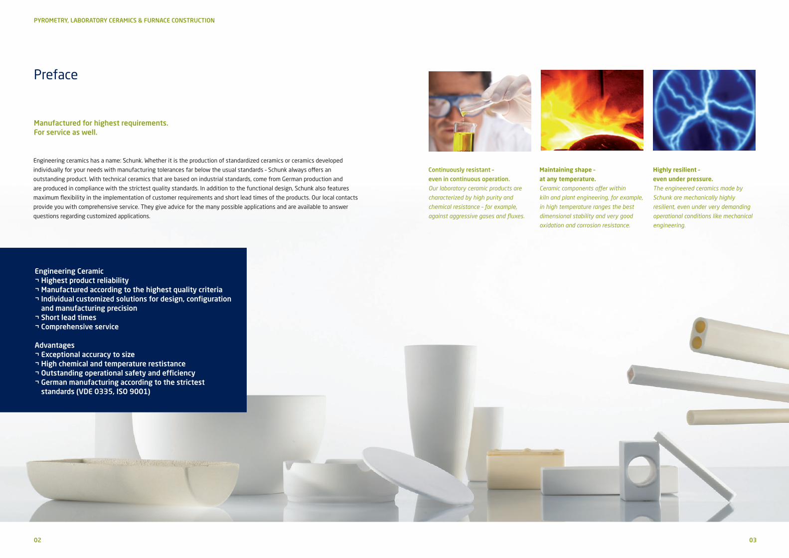
Technical data
04 05
PYROMETRY, LABORATORY CERAMICS & FURNACE CONSTRUCTION
10A H HE TEH
Unit AluSIK - 60 ZA
AluSIK - 80 GA
AluSIK - 80 ZA
AluSIK - 60 ZB
AluSIK - 99 GB
AluSIK -99 ZA
CarSIK - 70 ZA
CarSIK - 90 ZA
Type acc. DIN VDE 0335 C 610 C 530 — C 799 — —
Pages 6-8, 14-7 12, 14-15 13 9-11, 14-24 13 13
Mullite Corundum SillimaniteAluminium
oxideMullite-bonded
SiCMullite-bonded
SiC
AL2O3 content % 60 80 60 99.7 70 SiC* 90 SiC*
Type of body
Bulk densityg/cm3
Impervious
2.7
Porous
2.4
Porous
2.3
Impervious
3.8
Porous
2.1
Porous
2.2
Flexural strength20 °C (3-point) MPa 120 30 30 300 30 30
Open Porosity % 0 27 22 0 25 25
Limit of application °C 1400 1500 1400 1750 1400 1450
Thermal expansion20–1000 °C 10–6 K–1 5.5 5.8 6.5 8 5 5
Thermal conductivity20–100 °C W/mK 5 2 1.5 25 7 25
Thermal shock resistance Good Excellent Good Medium to good Excellent Excellent
Spec. electric resistance at RT Ω cm 1013 — — 1014 — —
600 °C 106 106 106 108 — —
Max. Manufacturing length for tubes mm 3000 3000 3000 3000 2200 1900
Qualities Unit ZirSIK-95 TA
Chemical analysis ZrO2 95 %CaO 4 %
Bulk density g/cm3 4.3
Open Porosity % 25
Limit of application· oxidizing · reducing· vacuum
°C240021002200
Thermal conductivity20–100 °C W/mK 2
Thermal expansion20–1000 °C 10-6K-1 9.6
These property values were determined with test pieces and
are used to determine the characteristics of our products
according to the best of our knowledge.
The realization of these values is strongly influenced by the
geometry of the product and the operational conditions.
*Addition of SiC to mix
Design of Standard Tubes
We use the following abbreviations in our order documentation:
The standard products in the catalog are identified by order numbers and are listed with the dimensions. The tubes are listed with OD and ID.
TUBES O = open on both ends
TUBES OF = open on both ends, with flange
TUBES G = closed on one end
TUBES GF = closed on one end, with flange
TUBES OFF = open on both ends, with 2 flanges
The desired lengths for tubes not standardized by a DIN standard are specified behind the letter „L“
in millimeters.
Flange dimensions are indicated in parenthesis as follows:
Flange diameter x heigt in mm, for example (F 40 x 5)
Insulating tubes:
A = 5, B = 10, C = 25, D = 50, E = 75 and F = 100 mm.
Insulating tubes with slot:
Please add an ”S“ behind the length specification, i. e.
for 2 bores 1 slot
for 4 bores 2 slots.

06 07
Mullite tubes
PYROMETRY, LABORATORY CERAMICS & FURNACE CONSTRUCTION
10A
H
HE
TEH AluSIK-60 ZA
10A
OD in mm ID in mm
1.5 0.8
2 1
3 1.5
3 2
4 2
5 3
6 4
7 4
8 5
9 6
10 7
11 7
12 8
14 10
15 11
16 12
17 13
18 14
19 13
19 15
20 15
22 18
22 15
24 19
26 20
OD in mm ID in mm
28 20
28 23
30 23
30 25
32 26
33 28
36 30
38 30
40 32
43 37
46 40
48 40
50 40
50 42
54 46
60 50
66 56
70 60
75 65
80 70
90 76
95 80
105 90
115 100
*Please ask us about larger and/or different dimension.
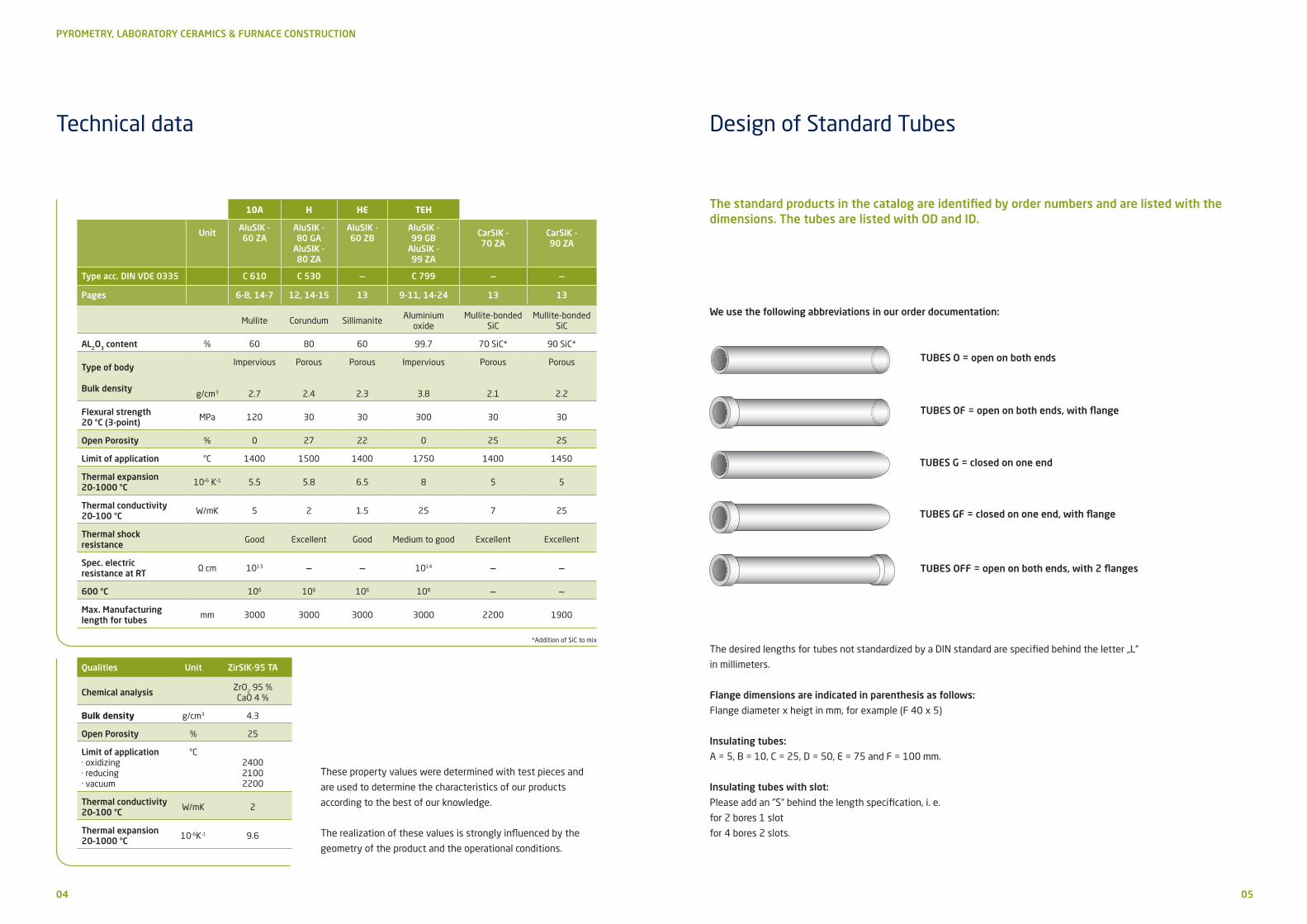
Insulating rods for thermocouples
AluSIK-60 ZA
10A
OD in mm ID in mm
2.2 0.5
3 0.8
3/2 oval 0.8
4 1
4.5 1.5
5/3 oval 1.6
6 1.8
7.5/4.5 oval 2.3
8 2
8.5 2.5
10 2.7
12 3
15.5 4.5
12/8 oval 4
OD in mm ID in mm
4 1
4.5 1
5.5 1.2
8.5 1.5
9 2.5
11 2.5
*Please ask us about larger and/or different dimension.
Type C 610 Type C 610
2-bore-rods 4-bore-rods
OD in mm Centre bore Ø in mm Bore Ø in mm
8.5 4 1.1
13.8 6 1.5
5-bore-rods with centre bore and 4 bores

08 09
Insulating tubes for thermocouples
PYROMETRY, LABORATORY CERAMICS & FURNACE CONSTRUCTION
10A
H
HE
TEH AluSIK-60 ZA
10A
Bores OD in mm ID in mm
2 2.2* 0.5
2 3* 0.8
2 4 1
4 4.5 1
4 5.5 1.2
2 6 1.8
2 8* 2
2 8.5* 2.5
4 8.5* 1.5
2 10* 2.7
2 12/8* oval 4
2 3/2 oval 0.8
2 5/3 oval 1.6
2 7.5/4.5 oval 2.3
4 9* 2.5
Aluminum oxide tubes
AluSIK-99 ZA
TEHType C 610 Type C 799
*Only for lengths of 25 and 50 mm.
OD in mm ID in mm
1* 0.5
1.5* 0.8
2* 1
2.7 1.7
3 1.2
3.5 2.5
4 2
5 3
6 4
7 4.5
For lengths:
¬ A = 5 mm,
¬ B = 10 mm,
¬ C = 25 mm,
¬ D = 50 mm,
¬ E = 75 mm,
¬ F = 100 mm
with one bore.
For lengths:
¬ A = 5 mm,
¬ B = 10 mm,
¬ C = 25 mm,
¬ D = 50 mm,
¬ E = 75 mm,
¬ F = 100 mm
with two and four bores.
OD in mm ID in mm
1 0.5
1.5 0.8
2 1
3 1.5
4 2
5 3
6 3
6 4
7 4
7 5
8 5
9 6
10 6
10 7
11 7
12 6
12 8
12 9
14 10
15 10
15 11
16 12
OD in mm ID in mm
17 12
20 15
22 17
24 18
27 17
27 20
30 21
30 23
32 25
35 27
38 30
40 30
42 34
46 38
50 40
58 48
60 50
65 55
70 60
75 65
80 68
*Only for lengths of 25 and 50 mm.
10 11
Insulating rods for thermocouples
PYROMETRY, LABORATORY CERAMICS & FURNACE CONSTRUCTION
10A
H
HE
TEH AluSIK-99 ZA
TEH
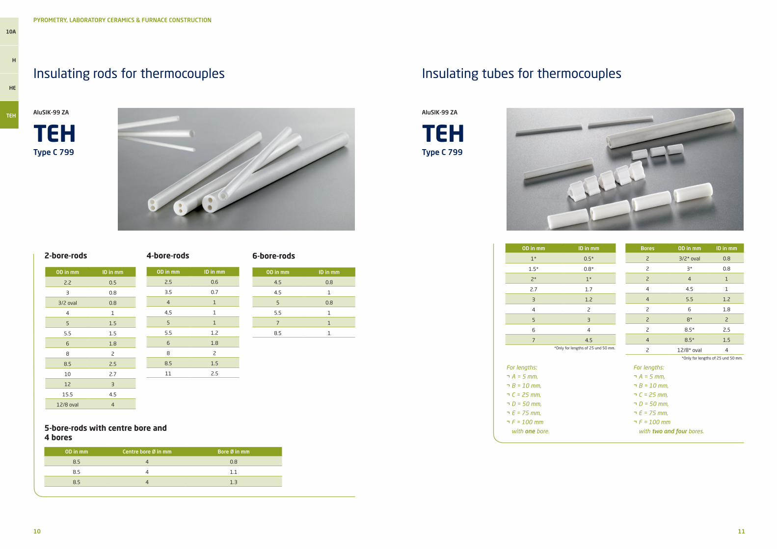
Insulating tubes for thermocouples
AluSIK-99 ZA
TEHType C 799 Type C 799
OD in mm ID in mm
2.2 0.5
3 0.8
3/2 oval 0.8
4 1
5 1.5
5.5 1.5
6 1.8
8 2
8.5 2.5
10 2.7
12 3
15.5 4.5
12/8 oval 4
OD in mm ID in mm
2.5 0.6
3.5 0.7
4 1
4,5 1
5 1
5.5 1.2
6 1.8
8 2
8.5 1.5
11 2.5
2-bore-rods 4-bore-rods
OD in mm Centre bore Ø in mm Bore Ø in mm
8.5 4 0.8
8.5 4 1.1
8.5 4 1.3
5-bore-rods with centre bore and 4 bores
OD in mm ID in mm
4.5 0.8
4.5 1
5 0.8
5.5 1
7 1
8.5 1
6-bore-rodsBores OD in mm ID in mm
2 3/2* oval 0.8
2 3* 0.8
2 4 1
4 4.5 1
4 5.5 1.2
2 6 1.8
2 8* 2
2 8.5* 2.5
4 8.5* 1.5
2 12/8* oval 4*Only for lengths of 25 und 50 mm.
OD in mm ID in mm
1* 0.5*
1.5* 0.8*
2* 1*
2.7 1.7
3 1.2
4 2
5 3
6 4
7 4.5
For lengths:
¬ A = 5 mm,
¬ B = 10 mm,
¬ C = 25 mm,
¬ D = 50 mm,
¬ E = 75 mm,
¬ F = 100 mm
with one bore.
For lengths:
¬ A = 5 mm,
¬ B = 10 mm,
¬ C = 25 mm,
¬ D = 50 mm,
¬ E = 75 mm,
¬ F = 100 mm
with two and four bores.
*Only for lengths of 25 und 50 mm.

12 13
Corundum tubes, Sillimanite supporting tubes
PYROMETRY, LABORATORY CERAMICS & FURNACE CONSTRUCTION
10A
H
HE
TEH AluSIK-80 ZA
H
Silicon carbide tubes
Type C 530
OD in mm ID in mm
16 10
20 12
22 15
23 17
26 18
30 20
30 22
35 26
35 28
40 30
40 32
50 40
60 50
65 55
70 60
OD in mm ID in mm
75 65
80 70
85 75
95 80
100 85
110 90
120 100
130 110
140 120
150 130
160 140
170 150
180 160
190 170
200 180
OD in mm ID in mm
15 7
18 12
20 12
22 16
23 13
25 12
25 15
25 18
Außen-ø mm Innen-ø mm
16 10
20 12
23 17
26 18
30 22
35 28
40 32
45 35
50 40
60 50
65 55
70 60
75 65
80 70
95 80
120 100
CarSIK-70 ZA
Außen-ø mm Bohrungs-ø mm
15 9
23 15
26 18
30 22
35 26
40 30
45 35
50 40
55 45
60 48
70 56
75 60
80 66
95 80
CarSIK-90 ZA
Maximum length 1900 mm
AluSIK-60 ZB
HEOD in mm ID in mm
30 20
35 25
40 30
45 35
50 40
55 45
60 48
14 15
Tolerances for pyrometer protection tubes
PYROMETRY, LABORATORY CERAMICS & FURNACE CONSTRUCTION
10A
H
HE
TEH
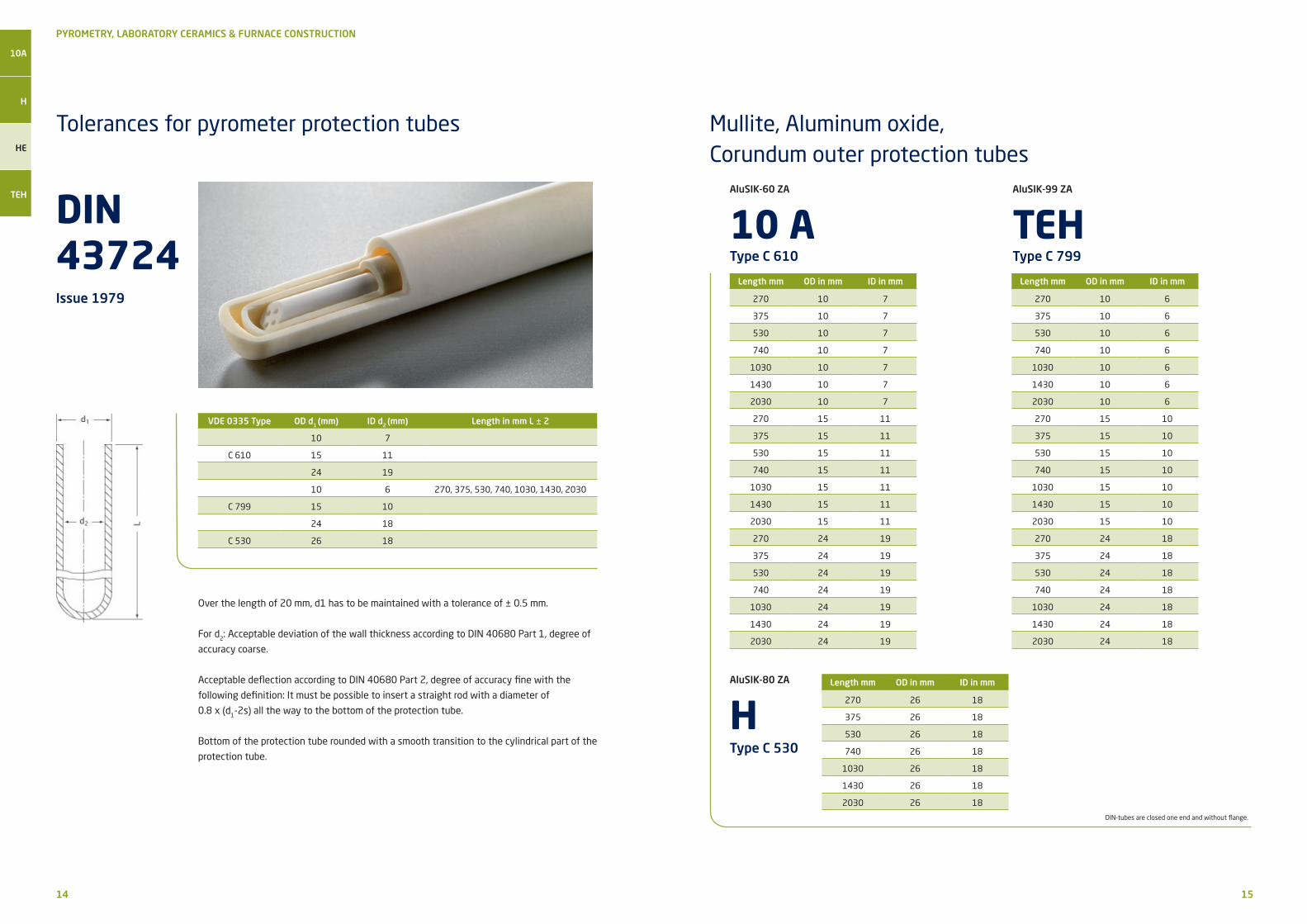
DIN 43724
Mullite, Aluminum oxide, Corundum outer protection tubes
Issue 1979
VDE 0335 Type OD d1 (mm) ID d2 (mm) Length in mm L ± 2
10 7
C 610 15 11
24 19
10 6 270, 375, 530, 740, 1030, 1430, 2030
C 799 15 10
24 18
C 530 26 18
Length mm OD in mm ID in mm
270 10 7
375 10 7
530 10 7
740 10 7
1030 10 7
1430 10 7
2030 10 7
270 15 11
375 15 11
530 15 11
740 15 11
1030 15 11
1430 15 11
2030 15 11
270 24 19
375 24 19
530 24 19
740 24 19
1030 24 19
1430 24 19
2030 24 19
DIN-tubes are closed one end and without flange.
Over the length of 20 mm, d1 has to be maintained with a tolerance of ± 0.5 mm.
For d2: Acceptable deviation of the wall thickness according to DIN 40680 Part 1, degree of
accuracy coarse.
Acceptable deflection according to DIN 40680 Part 2, degree of accuracy fine with the
following definition: It must be possible to insert a straight rod with a diameter of
0.8 x (d1-2s) all the way to the bottom of the protection tube.
Bottom of the protection tube rounded with a smooth transition to the cylindrical part of the
protection tube.
AluSIK-60 ZA
10 AType C 610
Length mm OD in mm ID in mm
270 10 6
375 10 6
530 10 6
740 10 6
1030 10 6
1430 10 6
2030 10 6
270 15 10
375 15 10
530 15 10
740 15 10
1030 15 10
1430 15 10
2030 15 10
270 24 18
375 24 18
530 24 18
740 24 18
1030 24 18
1430 24 18
2030 24 18
AluSIK-99 ZA
TEHType C 799
Length mm OD in mm ID in mm
270 26 18
375 26 18
530 26 18
740 26 18
1030 26 18
1430 26 18
2030 26 18
AluSIK-80 ZA
HType C 530

16 17
Tolerances for insulating tubes for thermocouples with 4 bores
PYROMETRY, LABORATORY CERAMICS & FURNACE CONSTRUCTION
10A
H
HE
TEH
DIN 43725
Mullite insulating tubes, Aluminum oxide insulating tubes
Issue 1990
VDE 0335 Type
OD d2
(mm) ± 0,3
Distance b (mm) ± 0,1
Bore-ø d3
(mm) ± 0,1
Length mm± 2
For Wire Ø(mm)
5.51) 2 1.2
C 610, C 799
275, 380, 560, 770, 1060, 1460, 2060
ø 0.8
8.51) 3 1.5
Length mm Bores OD in mm ID in mm
275 4 5.5 1.2
380 4 5.5 1.2
560 4 5.5 1.2
770 4 5.5 1.2
1060 4 5.5 1.2
1460 4 5.5 1.2
2060 4 5.5 1.2
275 4 8.5 1.5
380 4 8.5 1.5
560 4 8.5 1.5
770 4 8.5 1.5
1060 4 8.5 1.5
1460 4 8.5 1.5
2060 4 8.5 1.5
Also available with one or two slots.
1) It must be possible to insert an insulating tube with four bores of d2 = 5.5 mm into a tube
with an ID of 6 mm and it must be possible to insert an insulating tube with four bores of
d2 = 8.5 mm into a tube with an ID of 10 mm. It must be possible to insert a wire with a
diameter of 1 mm into the bores.
AluSIK-60 ZA
10 AType C 610
Length mm Bores OD in mm ID in mm
275 4 5.5 1.2
380 4 5.5 1.2
560 4 5.5 1.2
770 4 5.5 1.2
1060 4 5.5 1.2
1460 4 5.5 1.2
2060 4 5.5 1.2
275 4 8.5 1.5
380 4 8.5 1.5
560 4 8.5 1.5
770 4 8.5 1.5
1060 4 8.5 1.5
1460 4 8.5 1.5
2060 4 8.5 1.5
Also available with one or two slots.
AluSIK-99 ZA
TEHType C 799
18 19
Crucibles
PYROMETRY, LABORATORY CERAMICS & FURNACE CONSTRUCTION
Order # Height mm
OD at the topmm
Volumeccm
Wall thickness mm
T 001 ca. 39 ca. 44 22 2
T 002 ca. 59 ca. 60 75 3
T 003 ca. 78 ca. 72 160 3
T 004 ca. 89 ca. 82 240 3
T 005 ca. 97 ca. 82 250 3.5
T 006 ca. 168 ca. 99 780 4.5
T 007 ca. 225 ca. 135 1670 4.5
AluSIK-99 GB
Crucibles, conical shapeType C 799
Order # Height mm
OD at the topmm
Volumeccm
Wall thickness mm
T 110 17 20 3 2
T 111 23 30 9 2.5
T 112 30 40 24 3
T 113 40 50 45 3
T 114 50 61 80 3
T 115 56 70 120 3
T 116 62 80 180 3.5
Short crucibles, conical shapeType C 799
Order # Height mm
OD at the topmm
Volumeccm
Wall thickness mm
T 120 34 34 20 3
T 121 45 45 30 3
T 122 61 56 60 3
Tall crucibles, conical shapeType C 799
Crucibles
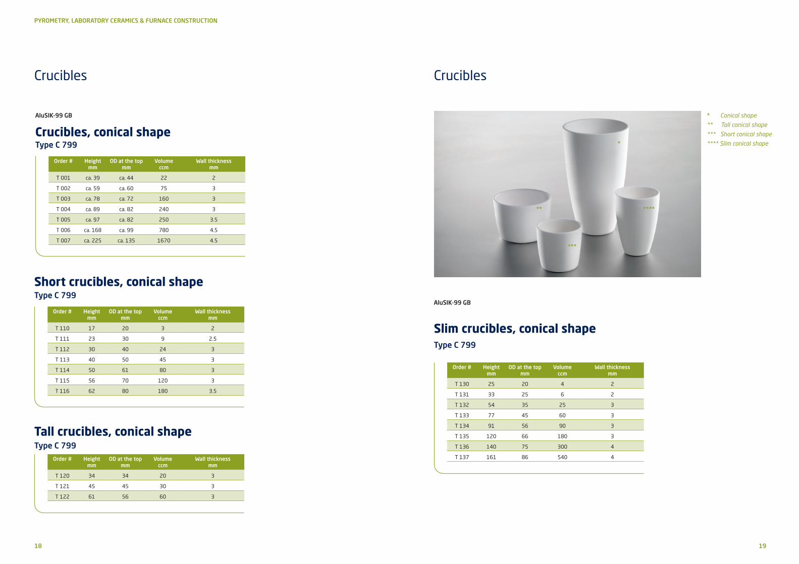
AluSIK-99 GB
Slim crucibles, conical shapeType C 799
* Conical shape
** Tall conical shape
*** Short conical shape
**** Slim conical shape*
**
***
****
Order # Height mm
OD at the top mm
Volumeccm
Wall thickness mm
T 130 25 20 4 2
T 131 33 25 6 2
T 132 54 35 25 3
T 133 77 45 60 3
T 134 91 56 90 3
T 135 120 66 180 3
T 136 140 75 300 4
T 137 161 86 540 4

20 21
PYROMETRY, LABORATORY CERAMICS & FURNACE CONSTRUCTION
Order # Lengt mm ø mm
T 010 100 18 x 14
T 011 100 22 x 17
T 012 100 28 x 23
T 013 100 34 x 28
T 014 100 38 x 32
T 015 100 42 x 36
T 016 100 49 x 43
T 017 100 53 x 45
T 018 100 60 x 51
T 019 100 66 x 56
T 020 200 38 x 32
T 021 200 42 x 36
T 022 200 49 x 43
T 023 200 53 x 45
T 024 200 61 x 51
T 025 200 66 x 56
Order # Height mm
OD at the top mm
Volumeccm
Wall thickness mm
T 140 6 6 0.5 1
T 141 13 10 1 1
T 142 63 18 9 2.5
T 143 46 23 12 2.5
T 144 113 33 50 3
Cylindrical crucibles with spherical bottomType C 799
AluSIK-99 GB
Cylindrical cruciblesType C 799
Crucibles, Ignition dishes
AluSIK-99 GB
Cylindrical cruciblesType C 799
Order # Height mm
OD at the topmm
Volumeccm
Wall thicknessmm
T 100 10 8 0.5 1
T 101 30 20 9 2
T 102 40 30 20 2.5
T 103 60 40 60 3
T 104 75 50 90 3
T 105 100 65 150 3
T 106 100 90 460 4
T 107 110 100 750 4
T 108 130 100 1000 4
AluSIK-99 GB
Ignition dishes, rectangular, conicalType C 799
Order # Length mm
Width mm
Heightmm
Wall thickness mm
Volume ccm
S 040 88 30 18 2.5 32
S 041 112 29 18 3 36
S 042 88 47 25 3 74
S 043 113 46 22 3 81
S 044 140 45 23 3 104
S 045 84 28 38 3 60
S 046 114 59 30 3.5 147
S 047 140 56 28 3.5 159
Crucibles

22 23
PYROMETRY, LABORATORY CERAMICS & FURNACE CONSTRUCTION
Boats, Dishes
AluSIK-99 GB
Boats, with or without eyeType C 799
Order # Length w/o eye mm
Width mm
Heightmm
Volume ccm
Wall thicknessmm
S 030 55 13 9 2.6 2.5
S 031 93 13 9 4.5 2.5
S 032 110 18 12 13 2.5
S 033 110 21 15 21 2.5
S 034 110 28 22 47 2.5
S 035 110 33 28 70 3
S 036 110 39 33 103 3
AluSIK-99 GB
BoatsType C 799
AA
D
B
C
Order # Dimensions mm Volume ccm
Wall thickness mmA B C D
S 100 53 8 8 38 0.5 2.5
S 101 80 15 10 60 4 2.5
S 102 86 15 10 73 5 2.5
S 103 100 20 17 70 11 3.5
S 104 111 13 10 95 5 3.5
S 105 162 20 15 143 20 3.5
S 106 200 20 14 175 23 3.5
Dishes
AluSIK-99 GB
Rectangular DishesType C 799
A B
D
C
AluSIK-99 GB
Ignition Basins, roundType C 799
A
C
B
Order # Dimensions mm Volume ccmA B C
S 110 12 8 2 0.3
S 111 25 11 2 3
S 112 41 16 2.5 13.7
S 113 66 16 3 36.7
Order # Dimensions mm Volume ccmA B C D
S 120 22 12 11 2.5 1
S 121 43 29 11 2.5 7.7
S 122 53 48 15 2.5 25
S 123 85 44 16 3 39

24 25
Lids, Adhesives and Mastics
PYROMETRY, LABORATORY CERAMICS & FURNACE CONSTRUCTION
Type C 799
Order # ø mm Height mm
T 150 8 2.5
T 151 20 3.5
T 152 25 3.5
T 153 29 4
T 154 35 2.6
T 155 40 5
T 156 45 5
T 157 50 4.5
T 158 55 4.5
All mastic must be stored above freezing temperatures.
Ready-to-use mastic need to be used up after opening.
Ready-to-use mastic can be stored for up to 3 months at the most;
clean tap water can be added, if necessary.
Order # ø mm Height mm
T 159 60 5.5
T 160 65 5
T 161 73 5
T 162 78 5
T 163 81 4.5
T 164 84 5
T 165 92 5.5
T 166 100 6
Adhesives and MasticsQuality Type Limit of application
AluSIK-60 FA Sillimanite 1600 °C ready-to-use mastic on sodium silicate basis
AluSIK-80 FB Corundum 1800 °C ready-to-use mastic on sodium silicate basis
ZirSIK-95 TA
Isostatically pressed crucibles
ØAØB
H1
H2
ZirSIK-95 TA
Rammed cylindrical crucibles
r
0,5°
d1
d2
h2
h1
Order # Dimensions mm Volume ccmø A ø B H1 H2
ISO 1 93 79 185 197 900
ISO 2 86 75 209 218 920
ISO 3 116 98 195 210 1450
*ISO 3 F 115 93 184 195 1240
ISO 4 60 50 120 128 230
ISO 5 65 53 190 200 410
ISO 6 147 124 237 250 2850
*ISO 6 F 147 124 237 250 2850
ISO 7 131 111 252 266 2420
ISO 8 42 32 115 120 90
ISO 9 88 68 130 150 470
ISO 10 85 45 130 150 200
Order # Dimensions mm
d1 d2 h1 h2 r
ZT 1 12 8 25 19 1
ZT 2 20 12 25 20 1
ZT 3 13 8 47 42 1
ZT 4 24 18 28 18 1
ZT 5 35 24 97 92 2
ZT 6 43 36 54 48 2
ZT 7 50 39 69 65 2
ZT 8 53 42 80 75 2
ZT 9 57 46 99 89 2
ZT 10 65 54 99 93 3
ZT 11 119 75 170 150 3
ZT 12 127 106 139 127 4
ZT 13* 120 100 22 180 10
ZT 14 215 175 295 255 4
ZT 15 150 127 155 135 5
ZT 16 170 140 185 165 5
AluSIK-99 GB
Lids
* with flat bottom
Customized products according to customer drawings available upon request.
Crucibles
* conical outer shape
26 27
Tolerances for diameter, length and deflection
PYROMETRY, LABORATORY CERAMICS & FURNACE CONSTRUCTION
Without grinding to DIN 40 680, issue 1983
Nominal dimensional range for diameter or other measurement
in mm (i.e. height, width etc.)
Degree of accuracy Nominal dimensionalrange for lengths in mm
Degree of accuracy
coarsePermissibledeviation
in mm
mediumPermissibledeviation
in mm
coarsePermissibledeflection fa in mm
mediumPermissibledeflectionfa in mm
up to 4 ± 0.4 ± 0.15 up to 30 ± 1.7 ± 0.15
above 4 up to 6 ± 0.6 ± 0.20 above 30 up to 40 ± 1.8 ± 0.20
above 6 up to 8 ± 0.7 ± 0.25 above 40 up to 50 ± 1.9 ± 0.25
above 8 up to 10 ± 0.8 ± 0.30 above 50 up to 60 ± 2.0 ± 0.30
above 10 up to 13 ± 1.0 ± 0.35 above 60 up to 70 ± 2.1 ± 0.35
above 13 up to 16 ± 1.2 ± 0.40 above 70 up to 80 ± 2.1 ± 0.40
above 16 up to 20 ± 1.2 ± 0.45 above 80 up to 90 ± 2.2 ± 0.45
above 20 up to 25 ± 1.5 ± 0.50 above 90 up to 100 ± 2.3 ± 0.50
above 25 up to 30 ± 1.5 ± 0.55 above 100 up to 110 ± 2.4 ± 0.55
above 30 up to 35 ± 2.0 ± 0.60 above 110 up to 125 ± 2.5 ± 0.65
above 35 up to 40 ± 2.0 ± 0.65 above 125 up to 140 ± 2.6 ± 0.70
above 40 up to 45 ± 2.0 ± 0.70 above 140 up to 155 ± 2.7 ± 0.80
above 45 up to 50 ± 2.5 ± 0.80 above 155 up to 170 ± 2.9 ± 0.85
above 50 up to 55 ± 2.5 ± 0.90 above 170 up to 185 ± 3.0 ± 0.90
above 55 up to 60 ± 2.5 ± 1.00 above 185 up to 200 ± 3.1 ± 1.00
above 60 up to 70 ± 3.0 ± 1.20 above 200 up to 250 ± 3.5 ± 1.25
above 70 up to 80 ± 3.5 ± 1.40 above 250 up to 300 ± 3.9 ± 1.50
above 80 up to 90 ± 4.0 ± 1.60 above 300 up to 350 ± 4.3 ± 1.75
above 90 up to 100 ± 4.5 ± 1.80 above 350 up to 400 ± 4.7 ± 2.00
above 100 up to 110 ± 5.0 ± 2.00 above 400 up to 450 ± 5.1 ± 2.25
above 110 up to 125 ± 5.5 ± 2.20 above 450 up to 500 ± 5.5 ± 2.50
above 125 up to 140 ± 6.0 ± 2.50 above 500 up to 600 ± 6.3 ± 3.00
above 140 up to 155 ± 6.5 ± 2.80 above 600 up to 700 ± 7.1 ± 3.50
above 155 up to 170 ± 7.0 ± 3.00 above 700 up to 800 ± 7.9 ± 4.00
above 170 up to 185 ± 7.5 ± 3.40 above 800 up to 900 ± 8.7 ± 4.50
above 185 up to 200 ± 8.0 ± 3.80 above 900 up to 1000 ± 9.5 ± 5.00
above 200 up to 250 ± 9.0 ± 4.20 above 1000 ± 1.5 + 0.8%xL ± 0.5 % xL
above 250 up to 300 ± 10.0 ± 4.60
above 300 up to 350 ± 11.0 ± 5.00
above 350 up to 400 ± 12.0 ± 5.50
above 400 up to 450 ± 13.0 ± 6.10
above 450 up to 500 ± 14.0 ± 6.80
above 500 up to 600 ± 15.0 ± 7.60
above 600 up to 700 ± 16.0 ± 8.30
above 700 up to 800 ± 17.5 ± 9.00
above 800 up to 900 ± 19.0 ± 9.50
above 900 up to 1000 ± 20.0 ± 10.00
above 1000 ± 0.02 x D ± 0.01 x D
Degree of accuracyVDE 0335, Type
coarse medium
530 610 799 530 610 799
cast and extruded parts within envelope size ø 30 mm and
above• • •
extruded parts up to envelope size ø 30 mm
• • •
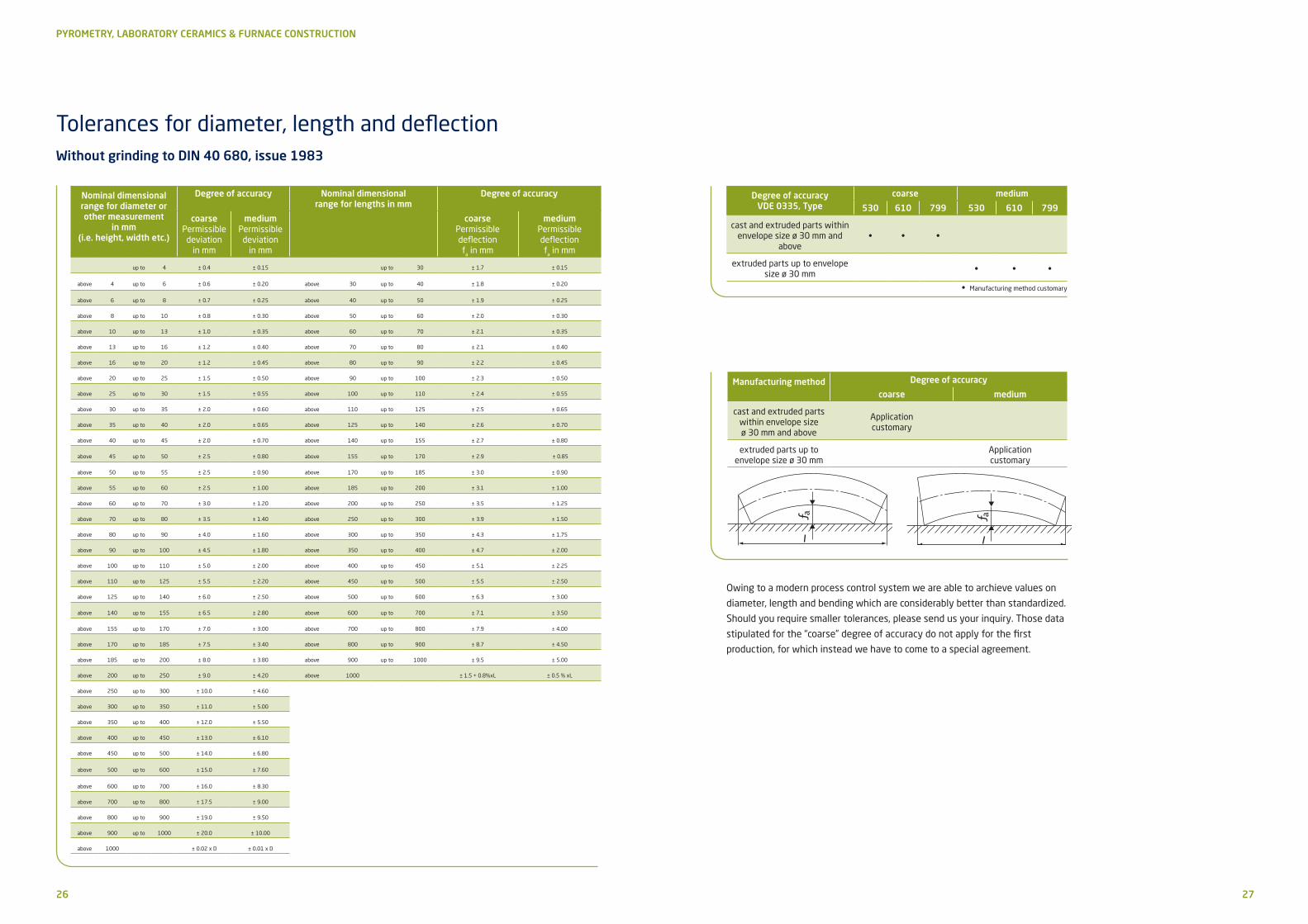
Manufacturing method Degree of accuracy
coarse medium
cast and extruded parts within envelope size ø 30 mm and above
Applicationcustomary
extruded parts up to envelope size ø 30 mm
Applicationcustomary
Owing to a modern process control system we are able to archieve values on
diameter, length and bending which are considerably better than standardized.
Should you require smaller tolerances, please send us your inquiry. Those data
stipulated for the “coarse” degree of accuracy do not apply for the first
production, for which instead we have to come to a special agreement.
• Manufacturing method customary
Schunk Ingenieurkeramik GmbH
Hanns-Martin-Schleyer-Strasse 5
47877 Willich-Münchheide ¬ Germany
Phone +49 2154 497 0
Fax +49 2154 497 111
E-Mail [email protected]
schunk-carbontechnology.com
05
.03
e/5
00
/20
18
Schunk Carbon Technology:Always at your side.Schunk Carbon Technology focuses on development, manufacture and application of carbon and ceramic solutions. It combines innovative spirit and technological expertise with exceptional customer service to provide a range of products and services unique to the market.
In Schunk Carbon Technology, you have a partner who can offer all the technological
possibilities of an international company and implement ideas custom-tailored to your
needs, both for high-volume industrial markets and for highly specialized niche
markets.
A Schunk Group divisionEnabling, idea-driven, cooperative – If you want to apply technology to develop better products and capture new markets, we can help.
The Schunk Group has been supporting customers with innovative technologies since
1913. As an idea-driven technology company, innovation is fundamental to our culture.
We forge long-lasting, cooperative working relationships with our clients.
You will find our custom-tailored, high-tech products and systems in markets such as;
carbon technology and ceramics, environment simulation and air-conditioning
technology, sintered metal and ultrasonic welding. The Schunk Group is active in many
key industries, including: automotive, rail, aviation, marine, solar, wind energy, chemical
and machine production. Our 8,100 employees in 29 countries are ready to serve you.
All specifications are subject to technical change. Texts and pictures are subject to copyright laws.Use of the content is not permitted without the written consent of Schunk Carbon Technology.