pak Suzuki marketing and Brand detailed report..............pak suzuki pak suzuki

SCHMEISER® TILL AN’ PAK
HYDRAULIC TRANSPORT KITS
ASSEMBLY & PARTS MANUAL
T.G. SCHMEISER CO., INC. P.O. BOX 1047 FRESNO, CA. 93714 (559) 268-8128 FAX (559) 268-3279
www.tgschmeiser.com
VERSION 1.6a 04- 2014
©COPYRIGHT 2014 T.G.SCHMEISER CO., INC.

2
INTRODUCTION
Your Schmeiser Till An’ Pak Hydraulic Transport Kit is designed to give you many years of dependable service. This manual has been prepared to instruct you in the safe and efficient operation of this machine. Read and study it thoroughly. Follow all instructions carefully.
Should your Hydraulic Transport Kit require replacement parts, go to your Schmeiser dealer. Always order genuine Schmeiser replacement parts.
If you need information not contained in this manual, contact your Schmeiser dealer.
Space has been provided below for you to record the model number of your Till An’ Pak Hydraulic Transport Kit. Be sure to bring this information with you to your dealer when ordering parts for your Hydraulic Transport Kit.
Thank you for buying a Schmeiser Till An’ Pak Hydraulic Transport Kit.
MODEL NUMBER ___________________________
DATE PURCHASED ___________________________
DEALER NAME ___________________________

3
TABLE OF CONTENTS
Introduction ................................................................................................................2
Table of Contents .......................................................................................................3
Till An’ Pak Hydraulic Transport Kit Models ...........................................................4
Safety Sheet ...............................................................................................................5
TPP3510 Transport Kit Assembly .............................................................................6
TPP3510 Transport Kit Assembly Instructions .........................................................7
TPP3520 Transport Kit Assembly .............................................................................8
TPP3520 Transport Kit Assembly Instructions .........................................................9
TPP3530 Transport Kit Assembly ............................................................................10
TPP3530 Wheel Axle Bearing Assembly .................................................................12
TPP3530 Wheel Axle Hub Assembly ........................................................................13
TPP3530 Transport Kit Assembly Instructions ........................................................14
TPP3540 Transport Kit Assembly ............................................................................15
TPP3540 Linkage Assembly ......................................................................................16
TPP3540 Wheel Leg Assembly .................................................................................17
TPP3540 Transport Kit Assembly Instructions .........................................................18
Hydraulic Transport Kits Hub Assembly .................................................................19
TPP3550 Transport Kit (Straddle Axle) Assembly ..................................................20
TPP3550 Wheel Axle Assembly ...............................................................................22
TPP3550 Heavy Duty Wheel Axle Assembly ...........................................................23
TPP3550 Transport Kit Assembly Instructions .........................................................24
Limited Warranty .......................................................................................................25
Maintenance and Repair Record ................................................................................26
Notes ..........................................................................................................................27

4
SCHMEISER®
HYDRAULIC TRANSPORT KIT MODELS
TPP3510 – TILL AN’ PAKS 2’-0” TO 10’-0”
TPP3520 – TILL AN’ PAKS 2’-0” TO 14’-0”
TPP3540 – TILL AN’ PAKS 8’-0” TO 24’-0”
TPP3540HD – TILL AN’ PAKS 16’-0” TO 24’-0”
TPP3530 – TILL AN’ PAKS 8’-0” TO 24’-0”
TPP3550 – STRADDLE AXLE -18’-0” TO 30’-0”

5
SAFETY
The safe operation of any machinery is an important concern to farmers and manufactures. There are obvious and hidden potential hazards involved in the operation of this implement. Carefully read and follow all safety precautions before operation. Serious injury or death may occur unless care is taken to insure the safety of both the operator and any other persons in the area.
1. Never permit anyone to ride on or walk beside the implement when moving.
2. Never permit anyone to ride on tractor when implement is being moved.
3. When performing operating functions, never allow anyone to be near the implement or thetractor.
4. Do not enter tractor when tractor is moving. Avoid serious injury or death from contactwith rotating tires. Enter and exit the tractor only when it is completely stopped.
5. Be sure of water, gas, sewer, or electric line locations before operating implement.
6. When in transport, use accessory lights and devices for adequate warning to operators ofother vehicles. Comply with all Federal, State and local laws when traveling on publicroads.
7. Use “Slow Moving Vehicle” emblem for warning vehicles approaching from the rear.
8. When transporting, remember that the implement may be wider than your tractor andextreme care must be taken to allow for safe clearance.
9. Never allow inexperienced or untrained personnel to operate the implement or tractorwithout supervision.
10. When using compressed air to clean implement, wear safety glasses.
11. Check all fasteners for tightness or damage before and after operation. Repair immediatelyif required.
12. Store implement in a stable position. Insure that safety equipment (lockouts, stands, pins,etc.) is secure and in place before detaching from tractor.

T. G. SCHMEISER CO., INC. TPP 3510 ASSEMBLY
S
C
H
M E
I
S
E
R
12
IN12IN
6(559) 268-8128 Fax (559) 268-3279 www.tgschmeiser.com
DescriptionRef No. Qty.
Lockout Bar for 4" X 12" Hyd. Cylinder6.1/2" X 1/2" 90-degree Adapters 5.4" X 12" Tie Rod Hydraulic Cylinder4.Center Frame Weldment3.Wheel Axle Bearing - UHMW2.End Mount Weldment LH (RH)1.
15" X 6" Wheel (See p.19 for Hub Assembly)8.Wheel Axle Weldment (specify size)7.
22112112
5/8" Lock Washer14.
5/8" X 5-1/2" Gr.5 NC Cap Screw13.
End Mount Bottom Clamp Plate12.
Center Frame Front Clamp Plate11.
1-1/8" X 6" Tongue Pin Weldment10.
7.6" X 15" Tire with Wheel (Optional)9.
21122
10
Part No.
GWD-412LB1FMBMJ9088GHC-40120THT1-00B000HT1-00C006HT1-00A000L(R)
GWT-156LBHHT1-(00)C000
LWASHER-10CSNC510088HT1-00A007HT1-00B007TPP3010GWT-761508
1/2" X 3" Gr.5 NC Cap Screw5/8" X 6-1/2" Gr.5 NC Cap Screw
16.
5/8" NC Hex Nut15.
1084CSNC508048
CSNC510096HXNUT-10NC
1/2" Lock Washer 4LWASHER-081/2" NC Hex Nut 4HXNUT-08NCSeal Kit for 4" X 12" Hyd. Cylinder 1PMCK-34000
17.
19.18.
2
TILL AN' PAKFRAME TILL AN' PAK
TONGUETILL AN' PAKROLLER
TILL AN' PAKBEARING
1
151314
11
5
4
3
9
6
19
7
8
1617 18
10
121314
SERIAL PLATEMANUAL CANISTER

T. G. SCHMEISER CO., INC. TPP 3510 ASSEMBLY INSTRUCTIONS
1. Lay Till An' Pak Frame on ground.
2. Unbolt Till An' Pak Frame from Pillow Block Bearings on Roller. Leave Roller attachedto Pillow Block Bearings.
3. Position each End Mount (1) between Till An' Pak Frame and Pillow Block Bearing (9).- Refer to the drawing for positioning.
4. Place Wheel Axle (7) with Plastic Bushings (2) between End Mounts (1).The Cylinderanchor on the Wheel Axle should be facing in the upward position.
5. Bring in End Mounts (1) and install and tighten all fasteners.- Use (4) 1/2" x 3" Bolts to fasten Pillow Block Bearing, End Mount, and Till An' Pak Frame.- Use (8) 5/8" x 6" Bolts to attach End Mount to Bottom Clamp Plate (11).
6. Remove Tongue Pin from Till An' Pak Frame. It is located at the base of the Frametongue guide.
7. Position Center Frame (3) on the tongue guide of the Till An' Pak frame. The two earsat the bottom of the center bracket should slide over the tongue guide pin hole of theTill An' Pak frame. The cylinder anchor portion of the Center Frame should be facingupward at a 45-degree angle aimed toward the rear of the unit. Refer to the drawing forthe positioning.
8. Place 1-1/2" x 6-1/2" Tongue Pin in the tongue guide hole. Remember, the tongue, theCenter Frame and the tongue guide hole on the frame all have to line up in order toproperly install the tongue pin.- Use (2) 5/8" x 5-1/2" Bolts to attach Center Frame to Front Clamp Plate.
9. Attach 4" x 12" Tie Rod Hydraulic Cylinder (4) to Center Frame and Wheel Axle. The rodclevis of the cylinder should attach to the wheel axle cylinder anchor.
10. Install Cylinder Lockout Bar (4). See drawing for proper installation.
11. Install tires on the wheel axle.
7(559) 268-8128 Fax (559) 268-3279 www.tgschmeiser.com

1918 20
S
CH
M E IS
E
R
12IN
12 IN
1
2
3
4
5 6
7
9 108
12
14
11 13
16
15
17
21
22
T. G. SCHMEISER CO., INC. TPP 3520 ASSEMBLY
(559) 268-8128 Fax (559) 268-3279 www.tgschmeiser.com8
DescriptionRef No. Qty.Part No.
2-1/2" X 8" Tie Rod Hyd. Cylinder6.
15 X 6 Wheel Rim (See p.19 for Hub Assembly)5.Lockout Plate4.Tire Axle Leg Weldment LH or RH3.Bracket Mounting Clamp2.Till An' Pak Mount Weldment LH or RH1.
5/8" X 6" NC Cap Screw Gr.58.1/2" MB - 3/8" MJ 90 Fitting 7.
12122
2410
3/4" X 2-1/2" Clevis Pin14.1-1/8" NC Hex Nut13.1-1/8" Lock Washer12.1-1/8" X 6" NC Cap Screw Gr.811.5/8" NC Hex Nut10.5/8" Lock Washer9. 10
102224
5/32" Wire Dia. Hair Pin Clip17.1" X 3-1/2" Cylinder Pin16.1/4" Lynch Pin15. 4
48
GHC-25080T
GWT-156LBHHT2-00B003HT2-00B000L(R)HT2-00A007HT2-00A000L(R)
CSNC510096FMBMJ9086
GPN-12X040HXNUT-18NCLWASHER-18CSNC818096HXNUT-10NCLWASHER-10
GPN-03CLIPGPN-1656HCGPN-040LYN
1/2" NC Hex Nut20.1/2" Lock Washer19.1/2" X 3" Gr.5 Cap Screw18. 4
44HXNUT-08NC
LWASHER-08CSNC508048
1/2" Flat Washer21. 4FWASHER-08
7.6 X 15 Tire with Wheel (Optional) 2GWT-761508

T. G. SCHMEISER CO., INC. TPP 3520 ASSEMBLY INSTRUCTIONS
1. Lay Till An' Pak Frame on ground.
2. Unbolt Till An' Pak Frame from Pillow Block Bearings on Roller. Do not remove Pillow Block
Berings from Roller.
3. Position each End Bracket (1) with attached Tire Axle Leg (3) between Till An' Pak Frame
and Pillow Block Bearing.
- Be sure to properly place left side and right side End Brackets in place. Refer to the
drawing for positioning.
- Use (4) 1/2" x 3" Bolts to fasten Pillow Block Bearings with Roller attached, End Brackets
with Tire Axle Legs attached, and Till An' Pak Frame.
All fasteners - hand tighten only!
4. Position Hydraulic Cylinder (6) with rod side facing toward wheel. Attach cylinder side
with Cylinder Pin (16). Next, position other end of Cylinder same way (Note: Elevation
of wheel may be necessary in order to align holes.)
5. Position Hydraulic Hose Manifold on tongue guide, with fittings facing toward rear
of unit. Manifold distance is adjustable. (Not shown on picture)
6. Connect retract and extend hoses to "T" fitting, then all lead hoses to tractor.
7. Securely tighten all fasteners.
(559) 268-8128 Fax (559) 268-3279 www.tgschmeiser.com9
10(559) 268-8128 Fax (559) 268-3279 www.tgschmeiser.com
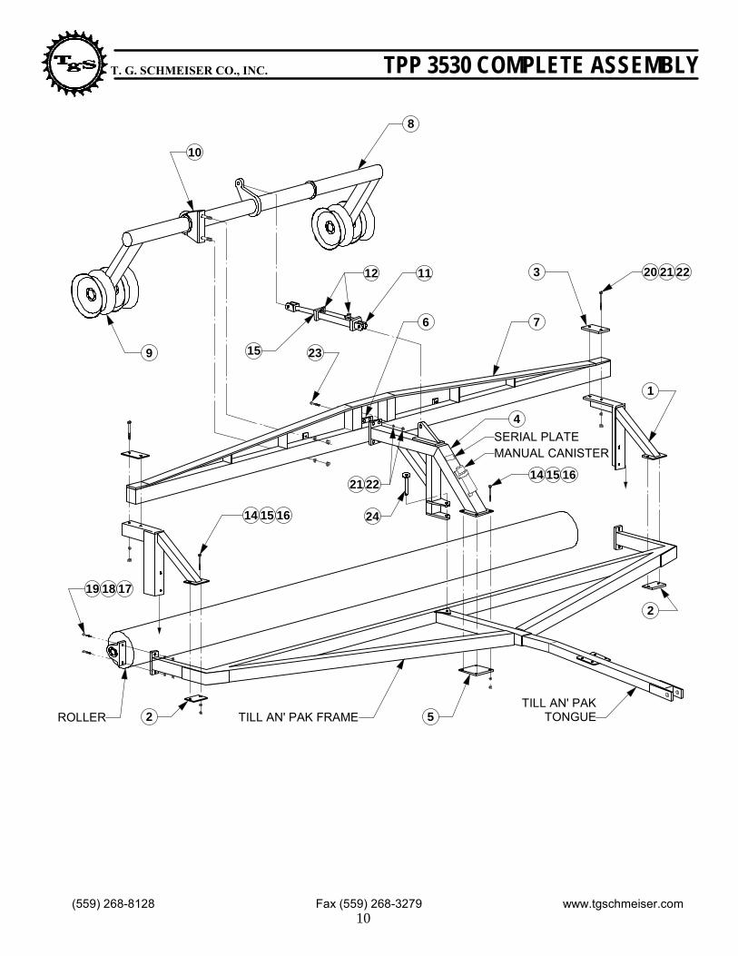
T. G. SCHMEISER CO., INC. TPP 3530 COMPLETE ASSEMBLY
1
TILL AN' PAK FRAMETILL AN' PAK
TONGUEROLLER
20 21 223
7
11
6
12
15 23
8
10
9
4
14 15 16
24
21 22
14 15 16
19 18 17
2 5
2
SERIAL PLATEMANUAL CANISTER

T. G. SCHMEISER CO., INC. TPP 3530 COMPLETE ASSEMBLY
DescriptionRef No. Qty.
Center Bracket to Cross Bar Clamp Plate6.
Center Bracket to Frame Clamp Plate5.
Center Bracket4.
End Bracket to Cross Bar Clamp Plate3.
End Bracket to Frame Clamp Plate2.
End Bracket Weldment LH (RH)1.
Wheel Axle Weldment8.
Main Bar Weldment (specify size)7.
2
2
2
1
1
1
1
1
1/2" X 1/2" 90-degree Adapters 12.
3-1/2" x 10" Tie Rod Hydraulic Cyl.11.
Wheel Axle Bearing Assembly (See p.12 for details)10.
15 X 6 Wheel (see p.19 for Hub Assembly)9. 4
2
1
2
Part No.
HT3-00A008
HT3-00A007
HT3-00A000
HT3-00B006
HT3-00B005
HT3-00B000L(R)
HT3-00C000
HT3-(00)D000
FMBMJ9088
GHC-35100T
SLL1353
GWT-156LBH
5/8" NC Hex Nut16.
5/8" Lock Washer15.
5/8" X 6" Gr.5 NC Cap Screw14.
Seal Kit for 3-1/2" x 10" Hyd. Cylinder13.
1/2" Lock Washer (15 ft. and under)18.
1/2" X 3" Gr.5 NC Cap Screw (15 ft. and under)17.
1
8
8
8
4
4
24.
3/4" X 5" Gr.5 NC Cap Screw23.
3/4" NC Hex Nut22.
3/4" Lock Washer21.
3/4" X 7-1/2" Gr.5 NC Cap Screw20.
1/2" NC Hex Nut (15 ft. and under)19. 4
4
8
8
4
HXNUT-10NC
LWASHER-10
CSNC510096
PMCK-33500
LWASHER-08
CSNC508048
CSNC512080
HXNUT-12NC
LWASHER-12
CSNC512120
HXNUT-08NC
5/8" X 3" Gr.5 NC Cap Screw (16 ft. and up) 4CSNC510048
5/8" Lock Washer (16 ft. and up) 4LWASHER-10
5/8" NC Hex Nut (16 ft. and up) 4HXNUT-10NC
GPN-18X104 1-1/8" X 6-1/2" Pin Weldment 1
11(559) 268-8128 Fax (559) 268-3279 www.tgschmeiser.com
7.6 X 15 Tire with Wheel (Optional) 4GWT-761508
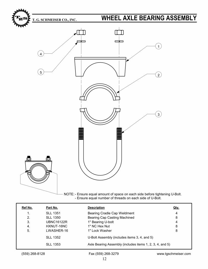
NOTE: - Ensure equal amount of space on each side before tightening U-Bolt.- Ensure equal number of threads on each side of U-Bolt.
1
2
3
4
5
Part No.
LWASHER-16HXNUT-16NCUBNC16122RSLL 1350SLL 1351
SLL 1352
SLL 1353
12
T. G. SCHMEISER CO., INC. WHEEL AXLE BEARING ASSEMBLY
DescriptionRef No. Qty.
1" Lock Washer5.1" NC Hex Nut4.1" Bearing U-bolt3.Bearing Cap Casting Machined2.Bearing Cradle Cap Weldment1. 4
8488
U-Bolt Assembly (includes items 3, 4, and 5)
Axle Bearing Assembly (includes items 1, 2, 3, 4, and 5)
(559) 268-8128 Fax (559) 268-3279 www.tgschmeiser.com

T. G. SCHMEISER CO., INC. TPP3530 HYDRAULIC TRANSPORT KIT HUB ASS'Y
8
7
42
96
5
1011
12
13
DescriptionPart No.Ref No.
(559) 268-8128 Fax (559) 268-3279 www.tgschmeiser.com
13
1
3
Quantity
GSP-14SPWA Spindle Washer
6. GHB-6X6STD Standard 6 on 6 Hub Assembly Complete(includes items 2, 3, 4, 5, 7, 8, 12)
5.
1/2" x 1" UNF Wheel Bolts for 6 on 6 Std. HubWHB-08X0164.
Grease SealGHB-6X6GSL3.
2" x 14" Removable Single Ended Spindle
2.
1.
Hub CapGHB-6X6CAP
9.
3/16" x 2" Cotter PinGPN-03X032C
8.
Spindle Castle NutGSP-14CANT
7.
15 x 6 Wheel - StandardGWT-156LBH
10.
HT3-00C200
7.6 x 15 8 Ply Tire with Wheel - OptionalGWT-761508
Inner Bearing Cone for 6 on 6 Std. HubGHB-6X6ICNInner Bearing Cup for 6 on 6 Std. HubGHB-6X6IRC
Outer Bearing Cup for 6 on 6 Std. HubGHB-6X6ORCOuter Bearing Cone for 6 on 6 Std. HubGHB-6X6OCN
11.12.
13.
2" x 20-1/4" Removable Double Ended SpindleTBU-01G016-
424
4
444444
44
44
22
212
2
222222
22
22
-
2-Wheel Option 4-Wheel Option
14 15 1617
7/16" NC Hex NutHXNUT-07NC7/16" Lock WasherLWASHER-077/16" x 3-1/2" Gr.5 NC Cap ScrewCSNC507056
1/2" x 1" Set ScrewSSNCS08X16
14.15.16.
17.
4444
4444

T. G. SCHMEISER CO., INC. TPP 3530 ASSEMBLY INSTRUCTIONS1. Lay Till An' Pak Frame on ground.
2. Unbolt Till An' Pak Frame from Pillow Block Bearings on Roller. Do not remove PillowBlock Bearings from Roller.
3. Position each End Bracket (1) between Till An' Pak Frame and Pillow Block Bearing.- Be sure that the angle iron leg of the End Bracket points inward. Refer to the drawing for positioning.- Use (4) 1/2" x 3" or (4) 5/8" x 3" Bolts to fasten Pillow Block Bearing, End Bracket, and Till An' Pak Frame.- Use (4) 5/8" x 6" Bolts to attach End Bracket - Roller Frame Mount Plate.All fasteners - hand tighten only!
4. Remove Tongue Pin from Till An' Pak Frame. It is located at the base of the Frametongue guide.
5. Position Center Bracket (4) on the tongue guide of the Till An' Pak frame. The two earsat the bottom of the center bracket should slide over the tongue guide pin hole of theTill An' Pak frame. The cylinder anchor portion of the Center Bracket should be facingupward at a 45-degree angle aimed toward the rear of the unit. Refer to the drawing forthe positioning.- Place 1-1/2" x 6-1/2" Tongue Pin in the tongue guide hole. Remember, the tongue, the Center Bracket and the tongue guide hole on the frame all have to line up in order to properly install the tongue pin. - Use (4) 5/8" x 6" Bolts to attach Center Bracket - Roller Frame Mount Plate.All fasteners - hand tighten only!
6. Position Main Cross Bar (7) on top of the End Bracket. The bar should be placed between thetwo holes on the topside of the End Bracket. The truss strap should be positioned on the topand the two sets of the Bearing Mount Plates welded on the Main Cross Bar should be placedto the back side of the machine.- Use (4) 3/4" x 5" Bolts to attach Center Bracket - Main Cross Bar Mount Plate.- Use (4) 3/4" x 7-1/2" Bolts to attach Main Cross Bar - End Bracket Mount Plate.All fasteners - hand tighten only!
7. Attach Wheel Axle (8) to Main Cross Bar (7) using the Bearing Assemblies. The Cylinderanchor on the Wheel Axle should be facing in the upward position.
8. Attach 3-1/2" x 10" Hydraulic Cylinder (13) to Center Bracket and Wheel Axle. The rod clevisof the cylinder should attach to the wheel axle cylinder anchor.
9. Securely tighten all fasteners.
14(559) 268-8128 Fax (559) 268-3279 www.tgschmeiser.com

1
2
3 4
65
7
8 8
8
3
T. G. SCHMEISER CO., INC. TPP 3540 ASSEMBLY
1-CYLINDER UNIT 2-CYLINDER UNIT (HEAVY DUTY)
DescriptionPart No.Ref No. Qty.
HT4-00A200 Pull Frame for 2-Cyl. Units6.HT4-00D000R Axle Leg with Hub, Right5.
Axle Leg with Hub, LeftHT4-00D000L4.Pull Frame PinHT4-00A0083.Main Frame for 1-Cyl. Units (specify size)HT4-(00)B1002.Pull Frame for 1-Cyl. UnitsHT4-00A1001. 1
12111
HT4-(00)B200 Main Frame for 2-Cyl. Units (specify size)7. 1
(559) 268-8128 Fax (559) 268-3279 www.tgschmeiser.com15
1-1/4" X 5-1/2" PinGPN-20CA038. 1 or 2

PULL FRAME
MAIN FRAMES
C I
S
E
R
12IN
12
IN
TILL AN' PAK ROLLER
1 2
3
45
6
8
9
7
12
7
10
1112
10
10
13
T. G. SCHMEISER CO., INC. TPP 3540 LINKAGE ASSEMBLY
DescriptionPart No.Ref No. Qty.
HT4-00A008 Pull Frame Pin6.FMBMJ9088 1/2" X 1/2" 90 degree Adapters5.
Lockout Bar for 4" X 16" Hydraulic CylinderGWD-416LB14.Hydraulic Cylinder Linkage WeldmentHT4-00C0003.Hydraulic Cylinder Linkage Pivot PlateHT4-00C0032.4" X 16" Tie Rod Hydraulic CylinderGHC-40160T1.
1/4" Lynch PinGPN-040LYN7.
1111233
Seal Kit for 4" X 16" Hydraulic CylinderPMCK-340008. 1
(559) 268-8128 Fax (559) 268-3279 www.tgschmeiser.com16
1-Cyl. 2-Cyl.
22224442
1" X 2-1/2" Std. Clevis PinGPN-16X04012.1" X 4-1/2" Std. Clevis Pin (red)GPN-16X06811.1/4" Cotter PinGPN-04X40C10.1" X 4" Cylinder PinGPN-1664HC9. 1
611
2822
1/2" X 3-1/2" Lockout Bar PinGPN-0856SL13. 1 2

T. G. SCHMEISER CO., INC. TPP 3540 WHEEL LEG ASSEMBLY
1
3
4
56
(559) 268-8128 Fax (559) 268-3279 www.tgschmeiser.com17
7
2
DescriptionPart No.Ref No. Qty. per Leg
9
8
1011
6.
5.
4.
3.
2" x 14" Single Ended Removable Spindle2.
Wheel Axle LegHT4-00D0001.
6 on 6 Hub Complete (see p.19 for Hub Assembly)GHB-6X6STD
7.
1
1
1
HT3-00C200
5/8" NC Hex NutHXNUT-10
5/8" NC Tri Bend U-BoltUBNC10X66T 6
12
5/8" Lock WasherLWASHER-10 12
Wheel Axle Leg SpacerHT4-00D006 3
10.
9.
8.
11.
7/16" X 3-1/2" NC Cap ScrewCSNC507056
1/2" X 1" NC Set ScrewSSNCS08X16 2
2
7/16" Lock WasherLWASHER-07 2
7/16" NC Hex NutHXNUT-07NC 2

T. G. SCHMEISER CO., INC. TPP 3540 ASSEMBLY INSTRUCTIONS
(559) 268-8128 Fax (559) 268-3279 www.tgschmeiser.com18
1. Lay Till An' Pak Roller on ground. Position Main Frame over Roller and bolt frame toPillow Block Bearings.- Use (4) 1/2" x 2-1/4" Gr.5 NC Bolts (14 ft. to 18 ft. units) or 5/8" x 2-1/2" Gr.5 NC bolts (19 ft. & up units.)
2. Position Wheel Leg between the bottom cross bars and top cross bar with wheel facingoutward (saddle mounting plates on bottom of wheel axle should face downward.)
3. Place saddle pads under wheel axle on two bottom cross bars (see Wheel Leg Assemblydrawing on page 16).
4. Position Wheel Leg to desired distance from side end of unit (spacing of wheel is basedupon customer's needs.)
5. Position third saddle between top cross bar and Wheel Leg. Tilt Wheel Leg and placeinto position (use of a mallet hammer may be necessary.)
6. Fasten Wheel Leg with two Tri-Bend U-Bolts on each mount.Same procedure is required for center Wheel Leg (wheels face inward, oppositedirection of end wheels.)
7. Mount tires to Wheel Legs and tighten (Tires are optional).
8. Fasten outer set of ears of Pull Frame to the Main Frame (1-1/4" x 5-1/2" yellow Pinand 1/4" Cotter Pin.) After fastening be sure to grease both zerk holes (see Assemblydrawing on page 14.)
9. Position Pivot Plate between Main Frame center ears and fasten with 1-1/4" x 5-1/2" yellowClevis Pin (refer to the drawing on page 15 for proper positioning).
10. Slide Pull Frame in front of Main Frame. Position 1-1/8" x 6-1/2" Tongue Pin in Pull Frame tongue hole.
11. Position Hydraulic Cylinder with rod facing toward rear of unit. Align holes with PivotPlate and lockout bar (elevation of Pull Frame may be necessary.)- Use 1" x 4-1/2" Red Clevis Pin with 1/4" Lynch Pn.
12. Remove plugs from cylinder before extending.
13. Thread in place (2) 90-degree adapters into cylinder.
14. Check tightness of all bolts and make sure all pins are in place.

T. G. SCHMEISER CO., INC. HYDRAULIC TRANSPORT KITS HUB ASSEMBLY
8
7
42
96
5
1011
12
13
DescriptionPart No.Ref No.
TPP3510
(559) 268-8128 Fax (559) 268-3279 www.tgschmeiser.com
19
1
3
TPP3520
Quantity per spindle
GSP-14SPWA Spindle Washer
6. GHB-6X6STD Standard 6 on 6 Hub Assembly Complete(includes items 2, 3, 4, 5, 7, 8, 12)
5.
1/2" x 1" UNF Wheel Bolts for 6 on 6 Std. HubWHB-08X016
4.
Grease SealGHB-6X6GSL
3.
2.
Hub CapGHB-6X6CAP
9.
3/16" x 2" Cotter PinGPN-03X032C
8.
Spindle Castle NutGSP-14CANT
7.
1
6
1
1
1
1
1
15 X 6 Wheel - StandardGWT-156LBH
10.
1
7.6 x 15 8 Ply Tire with Wheel - OptionalGWT-761508 1
Inner Bearing Cone for 6 on 6 Std. HubGHB-6X6ICN 1
Inner Bearing Cup for 6 on 6 Std. HubGHB-6X6IRC 1
Outer Bearing Cup for 6 on 6 Std. HubGHB-6X6ORC 1
Outer Bearing Cone for 6 on 6 Std. HubGHB-6X6OCN 1
11.
12.
13.
1
6
1
1
1
1
1
1
1
1
1
1
1
2" x 11" Single Ended Spindle1. 1GSP-32176S 1

20(559) 268-8128 Fax (559) 268-3279 www.tgschmeiser.com
3
5
6
7
124
TILL AN' PAKRING ROLLER
5
8
9
10
11
5
1314
1514
16
T. G. SCHMEISER CO., INC. TPP 3550 COMPLETE ASSEMBLY
12
17

21(559) 268-8128 Fax (559) 268-3279 www.tgschmeiser.com
T. G. SCHMEISER CO., INC. TPP 3550 COMPLETE ASSEMBLY
DescriptionRef No. Qty.
Straddle Axle Tongue Weldment6.
1/4" Lynch Pin5.
1" X 7" General Lock Pin Weldment4.
Pull Frame Assembly (specify size)3.
Wheel Axle Weldment2.
Straddle Axle Main Frame Weldment (specify size)1.
1" X 3" Standard Clevis Pin Weldment8.
Straddle Axle Ratchet Weldment7.
1
1
1
1
1
1
1
2
1/2" X 3-1/2" Swivel Lock Pin12.
Lockout Bar for 4" X 16" Hydraulic Cylinder SA11.
4" X 16" Tie Rod Hydraulic Cylinder10.
Straddle Axle Tongue Pin9. 1
1
1
1
Part No.
TSA-00E000
GPN-040LYN
GPN-16112L
TSA-(00)D000
TSA-00C000
TSA-(00)A000
GPN-16X048
TSA-00G000
GPN-0856SL
GWD-416LB2
GHC-40160T
TSA-00F003
FTP Pull Frame Hitch Clevis Weldment16.
1" X 8" Gr.5 NC Cap Screw15.
1" NC Hex Nylon Lock Nut14.
1" X 9" Gr.8 NC Cap Screw13.
Seal Kit for 4" X 16" Hydraulic Cylinder17.
1
4
2
1
1
FTP-00C000
CSNC516128
NYNUT-16NC
CSNC816144
PMCK-34000
Heavy Duty Wheel Axle Weldment 1TSA-00C100

1
2
4
10
11
12
13
14
9
53
8
6
7
DescriptionPart No.Ref No. Qty.
GSP-14SPWA Spindle Washer
6.GHB-6X6STD Standard 6 on 6 Hub Assembly Complete (includes items 3, 4, 5, 6, 8, 9, 13)
5.1/2" x 1" UNF Wheel Bolts for 6 on 6 Std. HubWHB-08X0164.Grease SealGHB-6X6GSL3.Wheel Axle Bearing Weldment2.Wheel Axle WeldmentTSA-00C0001.
Hub CapGHB-6X6CAP
9.
3/16" x 2" Cotter PinGPN-03X32C
8.
Spindle Castle NutGSP-14CANT
7.
12212
2
2222
10.
TSA-00B000
Inner Bearing Cone for 6 on 6 Std. HubGHB-6X6ICN 2Inner Bearing Cup for 6 on 6 Std. HubGHB-6X6IRC 2
Outer Bearing Cup for 6 on 6 Std. HubGHB-6X6ORC 2Outer Bearing Cone for 6 on 6 Std. HubGHB-6X6OCN 2
11.12.13.14. 9.5 x 15 8 Ply Tire with Wheel GWT-951508 2
22(559) 268-8128 Fax (559) 268-3279 www.tgschmeiser.com
T. G. SCHMEISER CO., INC. TPP3550 WHEEL AXLE ASSEMBLY

12
4
10
11
12
13
14
9
53
8
6
7
DescriptionPart No.Ref No. Qty.
GSP-14SPWA 7/8" Spindle Flat Washer
6.GHB-8X8HVY Heavy 8 on 8 Hub Assembly Complete (includes items 3, 4, 5, 6, 8, 9, 13)
5.Wheel Bolts for 8 on 8 Heavy HubWHB-09X0184.Grease SealGHB-8X8GSL3.Wheel Axle Bearing Weldment2.Heavy Duty Wheel Axle WeldmentTSA-00C1001.
Hub CapGHB-8X8CAP
9.
3/16" x 2" Cotter PinGPN-03X32C
8.
7/8" NF Spindle Castle NutGSP-14CANT
7.
14216
2
2222
10.
TSA-00B000
Inner Bearing Cone for 8 on 8 Heavy HubGHB-8X8ICN 2Inner Bearing Cup for 8 on 8 Heavy HubGHB-8X8IRC 2
Outer Bearing Cup for 8 on 8 Heavy HubGHB-8X8ORC 2Outer Bearing Cone for 8 on 8 Heavy HubGHB-8X8OCN 2
11.12.13.14. 12.5 x 16 14 Ply Tire with Wheel GWT-121614 2
23(559) 268-8128 Fax (559) 268-3279 www.tgschmeiser.com
T. G. SCHMEISER CO., INC. TPP3550 HEAVY DUTY WHEEL AXLE ASS'Y

T. G. SCHMEISER CO., INC. TPP 3550 ASSEMBLY INSTRUCTIONS
1. Lay Till An' Pak Roller on ground. Install flange bearings of ring roller shafts.
2. Position Main Frame over Roller and bolt frame and roller to flange bearings.
- Use (4) 5/8" x 2-1/2" Gr.5 NC bolts with lock washers and hex nuts.
3. Install Wheel Axle to Main Frame. Tighten wheel axle bearings onto main frame bearing mounts.
- Use 3/4" x 2" Gr.5 NC bolts with lock washers and hex nuts.
4. Install tire and wheel assemblies onto hubs on the wheel axle. Refer to page 22 (standard duty)
or 23 (heavy duty) for details.
5. Mount Pull Frame large brace (with clevis attached) to the main frame, then mount secondary brace
to the main frame.
- Use 1" x 8" Gr.5 NC bolts with nylon lock nuts.
Connect to each other for field use with lock pin. See drawing on page 20 for reference.
For transport, remove lock pin and swing both braces forward onto storage plate and secure
with same lock pin.
6. Install transport tongue. Fasten with 1" x 9" Gr.8 NC bolt and 1" nylon lock hex nut.
7. Install Ratchet weldment. Bushing side - to the tongue, clevis side - to main frame.
- Use 1" x 3" standard clevis pin with lynch pin on tongue side and cylinder pin with cotter pins
on main frame side.
8. Mount 4" x 16" Hydraulic cylinder to Main Frame and then to Wheel Axle. Install Lockout Bar.
Refer to assembly drawing on page 20 for details.
9. Install Jack Stand to front of Main Frame.
(559) 268-8128 Fax (559) 268-3279 www.tgschmeiser.com24

25
T.G. SCHMEISER CO., INC. ® Limited Warranty Statement
T. G. Schmeiser Co., Inc. warrants each new Schmeiser® product to be free from defects in material and workmanship. This warranty is applicable only for the normal service life expectancy of the product or components, not to exceed twelve (12) consecutive months from the date of delivery of the new Schmeiser product to the original purchaser.
Genuine T. G. Schmeiser Co., Inc. replacement parts and components will be warranted for 90 days from date of purchase, or the remainder of the original equipment warranty period, whichever is longer.
Under no circumstances will it cover any merchandise or components thereof, which, in the opinion of the company, has been subjected to misuse, unauthorized modifications, alteration, an accident or if repairs have been made with parts other than those obtainable through T. G. Schmeiser Co., Inc.
The Company in no way warrants engines, batteries, cylinders, tires or other trade accessories since these items are warranted separately by their respective manufacturer. Expendable components such as points, shanks, blades, rings, bearings, teeth, and the like are excluded from this warranty.
Our obligation under this warranty shall be limited to repairing or replacing, free of charge to the original purchaser, any part that, in our judgment, shall show evidence of such defect, provided further that such part shall be returned within thirty (30) days from date of failure to T. G. Schmeiser Co., Inc., routed through the dealer and distributor from whom the purchase was made, transportation charges prepaid.
This warranty shall not be interpreted to render T. G. Schmeiser Co., Inc. liable for injury or damages of any kind or nature to person or property. This warranty does not extend to the loss of crops, loss because of delay in harvesting, or any expense or loss incurred for labor, substitute machinery, rental or for any other reason.
Except as set forth above, T. G. Schmeiser Co., Inc. shall have no obligation or liability of any kind on account of any of its equipment and shall not be liable for special or consequential damages. T. G. Schmeiser Co., Inc. makes no other warranty, expressed or implied, and, specifically, T. G. Schmeiser Co., Inc. disclaims any implied warranty or merchantability or fitness for a particular purpose. Some states or provinces do not permit limitations or exclusions of implied warranties or incidental or consequential damages, so the limitations or exclusion in this warranty may not apply.
This warranty is subject to any existing conditions of supply, which may directly affect our ability to obtain materials or manufacture replacement parts.
T. G. Schmeiser Co., Inc. reserves the right to make improvements in design or changes in specifications at any time, without incurring any obligation to owners of units previously sold.
No one is authorized to alter, modify or enlarge this warranty nor the exclusion, limitations and reservations.
WARRANTY VOID IF NOT REGISTERED WITHIN 30 DAYS OF PURCHASE DATE

Schmeiser Till An' Pak Hydraulic Transport KitMaintenance & Repair Record
Date of Service or Repair Performed PartsService Replaced
26

Notes
27

Notes
28


![SCHMEISER V. BOWMAN: A COMPARATIVE ANALYSIS ......AkogyeramFinalMacro053016.docx (Do Not Delete) 7/12/16 1:34 PM 2016] Schmeiser v. Bowman 77 panies are granted exclusivity in the](https://static.fdocuments.net/doc/165x107/60fa1069f8ad2c0131078f32/schmeiser-v-bowman-a-comparative-analysis-akogyeramfinalmacro053016docx.jpg)