SCHEME - G Fifth Semester (CI-CC) - · PDF fileplans/maps/curves for execution of ... Set...
25
w.e.f Academic Year 2013-14 ‘G’ Scheme MSBTE - Final Copy Dt. 09/01/2015 GPDL 1 MAHARASHTRA STATE BOARD OF TECHNICAL EDUCATION, MUMBAI TEACHING AND EXAMINATION SCHEME FOR POST S.S.C. DIPLOMA COURSES COURSE NAME : DIPLOMA IN CIVIL ENGINEERING COURSE CODE : CC DURATION OF COURSE : EIGHT SEMESTERS WITH EFFECT FROM 2013-14 SEMESTER : FIFTH DURATION : 16 WEEKS PATTERN : CORRESPONDANCE - SEMESTER SCHEME : G SR. NO SUBJECT TITLE Abbrev iation SUB CODE TEACHING SCHEME EXAMINATION SCHEME SW (17905) PAPER HRS. TH (1) PR (4) OR (8) TW (9) TH TU PR Max Min Max Min Max Min Max Min 1 Advanced Surveying ASU 17963 05 01 48 03 100 40 50# 20 -- -- 50@ 20 50 2 Theory of Structures TOS 17964 07 01 -- 04 100 40 -- -- -- -- -- -- 3 Geo Technical Engineering GTE 17965 06 01 22 03 100 40 -- -- -- -- 50@ 20 4 Hydraulics HYD 17966 06 01 22 03 100 40 25# 10 -- -- 25@ 10 Total 24 04 92 -- 400 -- 75 -- -- -- 125 -- 50 TOTAL CONTACT HOURS DURING RESIDENT SESSION: 120 HRS [15 days * 8 hrs per day] Total Marks : 650 @ Internal Assessment, # External Assessment, No Theory Examination, * Online Examination. Abbreviations: TH-Theory, TU- Tutorial, PR-Practical, OR-Oral, TW- Term Work, SW- Sessional Work. NOTE: 1. HOURS MARKED BY * FOR INTERNAL PRACTICAL EXAMINATION TO BE CONDUCTED AT RESSIDENT SESSION. 2. ONE TEST OF 25 MARKS TO BE CONDUCTED AT RESIDENT SESSION AND MARKS TO BE SUBMITTED TO GPDL PUNE. 3. 240 HOURS FOR SELF STUDY AT HOME. 4. ALL PRACTICALS/ORAL EXAMS [EXTERNAL ASSESSMENT INDICATED BY #] TO BE CONDUCTED AT EXAM CENTRE. 5. ORAL EXAMINATION [INTERNAL ASSESSMENT @] TO BE CONDUCTED AT EXAM CENTRE. 6. INTERNAL ASSESSMENT @ OF TERM WORK WILL BE DONE AT RESIDENT SESSION.
Transcript of SCHEME - G Fifth Semester (CI-CC) - · PDF fileplans/maps/curves for execution of ... Set...

w.e.f Academic Year 2013-14 ‘G’ Scheme
MSBTE - Final Copy Dt. 09/01/2015 GPDL 1
MAHARASHTRA STATE BOARD OF TECHNICAL EDUCATION, MUMBAI TEACHING AND EXAMINATION SCHEME FOR POST S.S.C. DIPLOMA COURSES
COURSE NAME : DIPLOMA IN CIVIL ENGINEERING COURSE CODE : CC DURATION OF COURSE : EIGHT SEMESTERS WITH EFFECT FROM 2013-14 SEMESTER : FIFTH DURATION : 16 WEEKS PATTERN : CORRESPONDANCE - SEMESTER SCHEME : G
SR. NO SUBJECT TITLE Abbrev
iation SUB
CODE
TEACHING SCHEME
EXAMINATION SCHEME SW
(17905) PAPER HRS.
TH (1) PR (4) OR (8) TW (9) TH TU PR Max Min Max Min Max Min Max Min
1 Advanced Surveying ASU 17963 05 01 48 03 100 40 50# 20 -- -- 50@ 20
50 2 Theory of Structures TOS 17964 07 01 -- 04 100 40 -- -- -- -- -- --
3 Geo Technical Engineering GTE 17965 06 01 22 03 100 40 -- -- -- -- 50@ 20
4 Hydraulics HYD 17966 06 01 22 03 100 40 25# 10 -- -- 25@ 10
Total 24 04 92 -- 400 -- 75 -- -- -- 125 -- 50 TOTAL CONTACT HOURS DURING RESIDENT SESSION: 120 HRS [15 days * 8 hrs per day] Total Marks : 650 @ Internal Assessment, # External Assessment, No Theory Examination, * Online Examination. Abbreviations: TH-Theory, TU- Tutorial, PR-Practical, OR-Oral, TW- Term Work, SW- Sessional Work. NOTE: 1. HOURS MARKED BY * FOR INTERNAL PRACTICAL EXAMINATION TO BE CONDUCTED AT RESSIDENT SESSION. 2. ONE TEST OF 25 MARKS TO BE CONDUCTED AT RESIDENT SESSION AND MARKS TO BE SUBMITTED TO GPDL PUNE. 3. 240 HOURS FOR SELF STUDY AT HOME. 4. ALL PRACTICALS/ORAL EXAMS [EXTERNAL ASSESSMENT INDICATED BY #] TO BE CONDUCTED AT EXAM CENTRE. 5. ORAL EXAMINATION [INTERNAL ASSESSMENT @] TO BE CONDUCTED AT EXAM CENTRE. 6. INTERNAL ASSESSMENT @ OF TERM WORK WILL BE DONE AT RESIDENT SESSION.

w.e.f Academic Year 2013-14 ‘G’ Scheme
MSBTE - Final Copy Dt. 09/01/2015 PTD 2
MAHARASHTRA STATE BOARD OF TECHNICAL EDUCATION, MUMBAI TEACHING AND EXAMINATION SCHEME FOR POST S.S.C. DIPLOMA COURSES
COURSE NAME : DIPLOMA IN CIVIL ENGINEERING COURSE CODE : CI DURATION OF COURSE : EIGHT SEMESTERS WITH EFFECT FROM 2013-14 SEMESTER : FIFTH DURATION : 16 WEEKS PATTERN : PART TIME - SEMESTER SCHEME : G
SR. NO SUBJECT TITLE Abbrevi
ation SUB
CODE
TEACHING SCHEME
EXAMINATION SCHEME SW
(17905) PAPER HRS.
TH (1) PR (4) OR (8) TW (9) TH TU PR Max Min Max Min Max Min Max Min
1 Advanced Surveying ASU 17963 03 -- 04 03 100 40 50# 20 -- -- 50@ 20
50 2 Theory of Structures TOS 17964 03 -- -- 04 100 40 -- -- -- -- -- --
3 Geo Technical Engineering GTE 17965 03 -- 02 03 100 40 -- -- -- -- 50@ 20
4 Hydraulics HYD 17966 03 -- 02 03 100 40 25# 10 -- -- 25@ 10 Total 12 -- 08 -- 400 -- 75 -- -- -- 125 -- 50
Student Contact Hours Per Week: 20 Hrs. THEORY AND PRACTICAL PERIODS OF 60 MINUTES EACH. Total Marks : 650 @ Internal Assessment, # External Assessment, No Theory Examination, * Online Examination. Abbreviations: TH-Theory, TU- Tutorial, PR-Practical, OR-Oral, TW- Term Work, SW- Sessional Work. Conduct two class tests each of 25 marks for each theory subject. Sum of the total test marks of all subjects is to be converted out of 50 marks
as sessional work (SW). Progressive evaluation is to be done by subject teacher as per the prevailing curriculum implementation and assessment norms. Code number for TH, PR, OR and TW are to be given as suffix 1, 4, 8, 9 respectively to the subject code.

w.e.f Academic Year 2013-14 ‘G’ Scheme
MSBTE - Final Copy Dt. 09/01/2015 17963 CC/CI5 3
Course Name : Diploma in Civil Engineering
Course Code : CC / CI
Semester : Fifth
Subject Title : Advanced Surveying
Subject Code : 17963
Teaching and Examination Scheme:
Teaching Scheme Examination Scheme
TH TU PR PAPER HRS TH PR OR TW TOTAL
03 -- 04 03 100 50# -- 50@ 200
NOTE:
Two tests each of 25 marks to be conducted as per the schedule given by MSBTE.
Total of tests marks for all theory subjects are to be converted out of 50 and to be
entered in mark sheet under the head Sessional Work (SW).
Rationale: In search of precision and accuracy surveyor has to use more precise instruments like transit theodolite, micro optic theodolite, digital theodolite, total station and digital planimeter. Being a versatile instrument theodolite can be used more precisely for all civil engineering survey works. After studying theodolite survey student will able to precisely measure horizontal and vertical angles and calculate coordinates of various stations. After studying components of curve students will able to set the curve.
After studying Tacheometry student will able to find horizontal distances and elevations of various stations. After studying contouring student will able to prepare and interpret contour map.
With the use of planimeter student will able to calculate area of contour and volume occupied. It is intended to abreast with new technology for which study and use of Total station becomes inevitable.
Geographical Information System (GIS) is rapidly used in technological field which intend to assess real-world problems. GIS backed by modern computers allow us to benefit from visual power of maps. It is the time demand to nurture civil engineers with latest surveying technology. General objectives Students will be able to:
1. Understand handling and use of various survey instruments for field observations. 2. Understand linear and angular measurements 3. Select suitable instruments and appropriate method of survey. 4. Understand the preparation of maps from the field observations. 5. Interprete survey maps.

w.e.f Academic Year 2013-14 ‘G’ Scheme
MSBTE - Final Copy Dt. 09/01/2015 17963 CC/CI5 4
Learning Structure: Application Procedure
Principles Concepts Facts
Determining relative position various stations on ground and plotting plans/maps/curves for execution of civil engineering works.
Measuring horizontal and vertical distances
Measurement of Horizontal angle, Vertical angle
Direct and indirect methods
Locating and plotting the stations simultaneously
Setting the curve
Principal of Isosceles triangle
Phase difference
Deflection angle
Intersection of Equal elevation horizontalplanes
Phase difference
Contour, Contour interval, Horizontal equivalent, Grade contour
Fundamental axes of Theodolite,Consecutive coordinates
Constant of tacheometer, tacheometry
Electromagnetic waves
Radius of curve, Degree of curve
Micro waves
Contour maps
Theodolite
Tacheometer
Digital Theodolite, Digital level, Microoptic theodolite, Total station.
Curves
Remote sensing, GIS, GPS
Relationship amongst Fundamental axes

w.e.f Academic Year 2013-14 ‘G’ Scheme
MSBTE - Final Copy Dt. 09/01/2015 17963 CC/CI5 5
Contents: Theory Topic and Contents Hours MarksTopic 1. Contouring Specific objectives : State the meaning of contour, contour interval and horizontal equivalent. Carry out contouring by direct and indirect method Interpret features of ground from contour map Contents:
Concept of contour, contour interval and horizontal equivalent. Factors affecting contour interval, Characteristics of contours, Interpretation of ground features from contour map, Uses of contour map.
Methods of contouring, Direct method and Indirect method (block contouring, Longitudinal and cross sectioning) Interpolation of contour and its methods,
Concept of grade contour, Establishing grade contour on ground, Locating grade contour on contour map.
06 14
Topic 2. Area and Volume Measurement Specific objectives : Measure the area of plans/maps. Compute the volume
Contents: Instruments used for measuring the area- Polar Planimeter and Digital
Planimeter. Polar Planimeter- Component parts and procedure of measurement of area. Simple numerical problems.
Digital planimeter- Component parts and procedure of measurement. Computation of volume from contour maps by Trapezoidal and
Priszmoidal formulae, Simple numerical problems.
04 10
Topic 3. Theodolite Survey Specific objectives : Use the theodolite for measurement of horizontal angle, deflection angle,
magnetic bearing and vertical angle Carry out theodolite traversing Carry out calculations for Gale’s traverse table.
3.1 ……………………………………………………………(06) Types of theodolite, uses of theodolite, Component parts of transit
theodolite and their functions, Reading the vernier of transit thedolite, Technical terms- Swinging, Transiting, Face left, Face right, Fundamental axes of transit theodolite and their relationship
3.2 ……………………………………………………………(08) Temporary adjustment of transit theodolite, Measurement of horizontal
angle- Direct and Repetition method, Errors eleminated by method of repetition, Measurement of magnetic bearing of a line, Prolonging and ranging a line, Measurement of deflection angle, Measurement of vertical Angle. Permanent adjustment of transit theodolite (only relationship of different axes of theodolite)
3.3…………………………………………………………….(10) Thedolite traversing by included angle method and deflection angle
method. Check in open and closed traverse, Calculations of bearing from angles, Traverse computation-Latitude, Departure, Consecutive
12 24

w.e.f Academic Year 2013-14 ‘G’ Scheme
MSBTE - Final Copy Dt. 09/01/2015 17963 CC/CI5 6
cordinates, Independent cordinates, Balancing traverse by Bowditch’s rule and Transit rule, Gale’s table calculations, Simple numerical problems
Topic 4. Tacheometry Specific objectives : Use tacheometer to find horizontal and vertical distances Carry out contour survey by tacheometer
Contents: Meaning of tacheometer and tacheometry, Principle of tacheometry,
Essential requirement of tacheometer. Tacheometric formula for horizontal distance with telescope horizontal and staff vertical,Field method for determining constants of tacheometer, Determining horizontal and vertical distances with tacheometer by fixed hair method and staff held vertical, Limitation of tacheometry Simple numerical problems.
Contouring by tacheometer-Method and specific use.
06 12
Topic 5. Modern Survey Instrument Specific objectives :
Use the microoptic theodolite for measurement of horizontal and vertical angle
Use the digital theodolite for measurement of horizontal and vertical angle
Use the digital level for finding and recording reduced level. Use the total station for surveying work
Contents: 5.1 …………………………………………………………..(10)
Component parts and procedure to set and use microoptic theodolite for measurement of horizontal and vertical angle, Component parts and procedure to set and use digital theodolite for measurement of horizontal and vertical angle, Component parts and procedure to set and use digital level or finding and recording reduced level.
5.2 …………………………………………………………..(10) Component parts of total station, Minimum inventory required, Set up of
total station, Setting a back sight, Azimuth mark, Measurement with total station, General setting required for all stations, Field book recording, Radial shooting, Survey station description by codes, Instrument station entry, Data retrieval, Field generated graphics, Lay out using Total station.
10 20
Topic 6. Curves Specific objectives: List components of simple circular curve Set simple circular curve by offsets from long chord and Rankine’s
deflection angle method Contents:
Necessity of curve, Classification of curve, Notation of simple circular curve, Designation of curve
Setting simple circular curve by offsets from long chord and Rankine’s deflection angle method, Simple numerical problems.
06 12
Topic 7. Remote sensing and GIS Specific objectives: Descibe remote sensing process Identify the components of GIS
04 08

w.e.f Academic Year 2013-14 ‘G’ Scheme
MSBTE - Final Copy Dt. 09/01/2015 17963 CC/CI5 7
State applications of GPS Contents:
Definition of remote sensing, Concept of remote sensing, Types of remote sensing system-Passive system, Active system, Distance of remote sensing, Remote sensing data, Remote sensing processs, Application of remote sensing, Advantages of remote sensing, Limitations of remote sensing
Definition of GIS, Key components of GIS, Application of GIS in Land information, Environmental field.
Introduction to GPS, Application of GPS in civil engineering.Total 48 100
Practicals: Skills to be developed:
Instructions: Intellectual Skills: Understand different instruments for linear measurement and leveling.
Understand the method of taking observations with the survey instruments.
Understand specific use of various types of survey instruments.
Identify the errors of the survey instruments.
Motor Skills: Measure distances, Bearings and finding Reduced Levels with various survey instruments.
Recording of survey field data collected in Field Book and Leveling Book.
Prepare drawing (plans/maps) using survey data.
Reading and Interpretation of drawing (plans/maps).
List of Practicals: Group size for survey practical shall be about five students. Each teaching staff shall handle maximum two groups. Students shall record the observations in Field Book at field itself. One full day per project is required for project survey work. Drawing and plotting should be considered as a part of practical. Term work shall consists of record of all practicals and projects in field book and drawing
sheets for the given projects. 1. Carry out Block contouring of plot 30 m x 30 m with each block 5mx5m 2. Locate a contour on a field by direct contouring method. 3. To find area of given contour map with polar planimeter and digital planimeter 4. Understanding different components of transit theodolite, Temporary adjustment and
reading the vernier and recording it. 5. Measurement of horizontal angle by transit theodolite (direct method) 6. Measurement of horizontal angle by transit theodolite (repetition method) 7. Measurement of magnetic bearing by transit theodolite 8. Measurement of deflection angle by transit theodolite 9. Measurement of vertical angle by transit theodolite 10. Find constants of tacheometer 11. To find horizontal distance and elevation of given object with tacheometer

w.e.f Academic Year 2013-14 ‘G’ Scheme
MSBTE - Final Copy Dt. 09/01/2015 17963 CC/CI5 8
12. Measure horizontal and vertical angle with micro-optic theodolite 13. Measure horizontal and vertical angle with digital theodolite 14. Use total station for measuring horizontal angle, vertical angle, horizontal distance,
sloping distance, vertical distance. 15. Layout with total station 16. Setting curve by offset from long chord method 17. Setting curve by Rankine’s deflection angle method
Mini Projects:
1. Carry out Block contouring project for a plot 100mx120m with a block size 10mx10m plot the contours on imperial drawing sheet.
2. Theodolite survey for a closed traverse (5-6) sides and locating the details of buildings. Plotting the Gale’s table and traverse on A1 size imperial drawing sheet.
3. Carry out block contouring using total station for a plot of 100x120 meter with block size of 5 m x5m on sloping ground and locate the building layout up to 100 square meter on site. Prepare the contour map and centre line plan on A-1 size imperial sheet.
Learning Resources: Books :
Sr. No. Title Author Publisher
1 Surveying and Leveling- 38 th edition. N.N. Basak Tata McGraw Hill
2 Surveying- Volume-I, II Third Edition S.K. Duggal Tata McGraw Hill
3 Surveying and Leveling-1,II T.P. Kanetkar and Kulkarni Pune Vidyarthi Grigh Prakashan
4 Surveying and Leveling-1 Dr. B.C. Punmia Laxmi Publication 5 Surveying and Leveling R. Subramanian Oxford university press 6 Advance Surveying Satheesh Gopi, N. Madhu Pearson 7 Remote sensing and GIS Basudeo Bhatta Oxford university press 8 Surveying,( seventh edition) Arthur Bannister Pearson

w.e.f Academic Year 2013-14 ‘G’ Scheme
MSBTE - Final Copy Dt. 09/01/2015 17964 CC/CI5 9
Course Name : Diploma in Civil Engineering
Course Code : CC / CI
Semester : Fifth
Subject Title : Theory of Structures
Subject Code : 17964
Teaching and Examination Scheme:
Teaching Scheme Examination Scheme
TH TU PR PAPER HRS TH PR OR TW TOTAL
03 -- -- 04 100 -- -- -- 100
NOTE:
Two tests each of 25 marks to be conducted as per the schedule given by MSBTE.
Total of tests marks for all theory subjects are to be converted out of 50 and to be
entered in mark sheet under the head Sessional Work (SW).
Rationale:
Civil engineering structures are mainly made-up of column, Beam and Slabs and these structures are subjected to axial as well as eccentric loading. These structures may be determinant or indeterminate in nature. The members like fixed beam, continuous beam, portal frame are indeterminate structures.
The content on calculations of actual shear stresses, bending moments and deflections which are developed in various structural members will be useful in analyzing the forces in these members which is further useful in design of these members. Analysis of member for deflection, combined direct and bending stresses will be useful in safe design of various structural members.
Thus the total contents of this subject forms the basic for the efficient and safe design of steel and RCC structures. . General Objectives: The students will be able to-
1. Understand the stresses in the members due to eccentric load and wind pressure 2. Understand shear force and bending moment diagram for Fixed and continuous beams for
various external loading on them. 3. Understand the shear force and bending moment diagrams for beams subjected to point
load and uniformly distributed load. 4. Understand analysis of forces in various members of steel roof trusses for different spans.
w.e.f Academic Year 2013-14 ‘G’ Scheme
MSBTE - Final Copy Dt. 09/01/2015 17964 CC/CI5 10
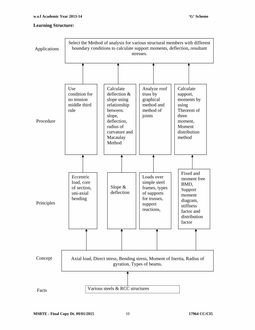
Learning Structure: Theory:
Facts Various steels & RCC structures
Select the Method of analysis for various structural members with different boundary conditions to calculate support moments, deflection, resultant
stresses.
Calculate deflection & slope using relationship between. slope, deflection, radius of curvature and Macaulay Method
Use condition for no tension middle third rule
Analyze roof truss by graphical method and method of joints
Fixed and moment free BMD, Support moment diagram, stiffness factor and distribution factor
Loads over simple steel frames, types of supports for trusses, support reactions,
Slope & deflection
Eccentric load, core of section, uni-axial bending
Axial load, Direct stress, Bending stress, Moment of Inertia, Radius of
gyration, Types of beams.
Calculate support, moments by using Theorem of three moment, Moment distribution method
Applications
Procedure
Principles
Concept

w.e.f Academic Year 2013-14 ‘G’ Scheme
MSBTE - Final Copy Dt. 09/01/2015 17964 CC/CI5 11
Theory Content:
Topic and Contents Hours MarksTopic 1: Direct and Bending Stresses Specific Objectives: List direct and eccentric loads on columns. Write conditions of no tension for beams, columns and pillars. Draw stress distribution diagram at bases of column, pillars and
chimneys subjected to wind pressure. Contents: 1.1 ……………………………………………………..(12 Marks)
Introduction of direct and eccentric loads, Eccentricity about one principal axis, nature of stresses Maximum and minimum stresses, resultant stress distribution
diagram. Condition for no tension or zero stress at extreme fiber Limit of eccentricity, core of section for rectangular and circular
cross sections Middle third rule.
1.2 ……………………………………………………..(08 Marks) Chimneys subjected to wind, rectangular and circular cross section,
wind pressure, coefficient of wind pressure, stress distribution diagram at base.
Walls subjected to horizontal pressure & stress distribution at base.
10
20
Topics 2: Slope and Deflection Specific Objectives: State meaning of slope and deflection and stiffness of simply supported
beams and cantilevers. Calculate slope and deflection of simply supported and cantilever beam
subjected to point load and UDL by Macauley method. State relationship between slope and deflection and radius of curvature.
Contents: 2.1 ……………………………………………………..(08 Marks)
Concept of slope and deflection, stiffness of beams. Relation among bending moment, slope deflection and radius of
curvature, differential equation (no derivation), double integration method to find slope and defection of simply supported and cantilever beam.
2.2 ……………………………………………………..(12 Marks) Macaulay’s method for slope and deflection, application to simply
supported and cantilever beam subjected to concentrated and uniformly distributed load on entire span,.
10
20
Topics 3: Fixed Beam Specific Objectives: State meaning of fixity effects and list advantages of fixed beam. Write the principle of superposition. Draw BMD and SFD for fixed beams with point load and UDL.
Contents: Fixed Beam
06 12

w.e.f Academic Year 2013-14 ‘G’ Scheme
MSBTE - Final Copy Dt. 09/01/2015 17964 CC/CI5 12
Concept of fixity, effect of fixity, advantages and disadvantages of fixed beam.
Principle of superposition. Fixed end moments from first principle for beam subjected to UDL
over entire span, central point load, Point load other than mid span. Application of standard formulae in finding moments and drawing
S.F. and B.M. diagrams for a fixed beam (Derivation need not be asked in the examination).
Topics 4: Continuous Beam Specific Objectives: State the effects of continuity of beams and nature of moments induced. Write Calpeyron’s theorem of three moments (No derivation) Draw sketches of BMD and SFD for continuous beams.
Contents: Continuous Beam
Definition, effect of continuity practical example, nature of moments induced due to continuity, concept of deflected shape
Clapeyron’s theorem of three moment (no derivation). Application of theorem maximum up to three spans and two
unknown support moment only, Support at same level, spans having same and different moment of inertia subjected to concentrated loads and uniformly distributed loads over entire span.
Drawing SF and BM diagrams for continuous beams.
08 16
Topics 5: Moment Distribution Method Specific Objectives: List introduction and sign convention for fixed end moments. State meaning of carry over factor, stiffness factor and distribution
factor. Draw BMD, SFD with support at same level.
Contents: Moment Distribution Method.
Introduction, sign convention Carry over factor, stiffness factor, distribution factor. Application of moment distribution method for various types of
continuous beams subjected to concentrated loads and uniformly distributed load over entire span having same or different moment of inertia up to three spans and two unknown support moment only, SF and BM diagrams (Supports at same level)
Introduction to portal frames – Types of portal frames (No problems shall be asked on portal frames).
08 16
Topic 6: Simple Frames Specific Objectives: List different types of roof trusses. State conditions for redundant and non- redundant frames. List types of forces in different members.
Contents: Simple Frames
Types of trusses (Simple, Fink, compound fink, French roof truss,
0 6 16

w.e.f Academic Year 2013-14 ‘G’ Scheme
MSBTE - Final Copy Dt. 09/01/2015 17964 CC/CI5 13
pratt roof truss, Howe roof truss, North light roof truss, King post and Queen post roof truss)
Calculate support reactions for point loads at nodal points. Calculate forces in different members by using method of joints and
Method of sections. Graphical method of analysis of truss.(No problem in the theory
examination) Total 48 100
Tutorial:
Questions from any two old QP shall be given for tutorial on each topic. Students shall solve these problems in a separate note book. The staff member shall assess these work batchwise.
Learning Resources: Books: Sr. No. Author Title Publisher
01 S. B. Junnarkar Mechanics of structures Volume-I,II
Charotar Publishing House, Anand
02 S. Ramanrutham Theory of Structures Dhanpatrai & Sons, Delhi
03 R. S. Khurmi Theory of Structures S.Chand Publications, Delhi
04 G.S. Pandit & S.P.Gupta Theory of Structures Tata Mcgraw Hill
05 West Fundamentals of Structural Analysis Wiley India

w.e.f Academic Year 2013-14 ‘G’ Scheme
MSBTE - Final Copy Dt. 09/01/2015 17965 CC/CI5 14
Course Name : Diploma in Civil Engineering
Course Code : CC / CI
Semester : Fifth
Subject Title : Geo Technical Engineering
Subject Code : 17965
Teaching and Examination Scheme
Teaching Scheme Examination Scheme
TH TU PR PAPER HRS TH PR OR TW TOTAL
03 -- 02 03 100 -- -- 50@ 150
NOTE:
Two tests each of 25 marks to be conducted as per the schedule given by MSBTE.
Total of tests marks for all theory subjects are to be converted out of 50 and to be
entered in mark sheet under the head Sessional Work (SW).
Rationale:
Geotechnical engineering is the important for every structure, since all structures rest on soil. The stability of these structures depends upon behavior of soil and bearing capacity of soil to carry loads under different loading conditions. Formation of soil and rocks, defects in rocks, soil behavior, and soil as an engineering material are essential parameter to an engineer. The design of foundation of buildings, dams, towers, embankments, roads, railways, retaining walls, bridges is mainly governed by these above stated parameters.
The content of this subject are also useful in designing basement, underground tank and underwater structures. Knowledge of geology, soil characteristics, and stress distribution under loading on soil, bearing capacity of soil is also useful to every engineer in the design, execution and stability analysis of structures. General Objectives: Students will be able to
1) Know types of rocks and their formation, ground water table, detail investigation, mineralogy, earthquake forces and their effects.
2) Understand the structure and sub soil strata of earth. 3) Understand the causes and effects of earth quake 4) Understand soil properties and interpretation of results of test on soil. 5) Understand the suitability of foundation based on soil condition at site. 6) Know importance of shear strength, bearing capacity, stability of slopes and techniques of
stabilization of soil.

w.e.f Academic Year 2013-14 ‘G’ Scheme
MSBTE - Final Copy Dt. 09/01/2015 17965 CC/CI5 15
Learning Structure: Application
Procedure
Concept Fact
Identify the type of Rock and soil through determination of physical properties and stabilization techniques during construction of foundation of structure. To handle situation where marshy land, loose soil and soil of low bearing is available.
Establish functional relationship between properties of Soil. Sketches of folds,faultsand Joints.
Determine Index Properties of Soil using I. S. Code methods and classify the Soil.
Determine the permeability of Soil applying Darcy’s Law by Constant head & falling head Test
Performing Proctor test to obtain OMC & MDD and improve Soil properties through soil stabilization methods
Calculate shearing strength from shear test on Soil and applying Coulomb’s Law
Calculate bearing Capacity of Soil by I.S. Code Method.
Soil as three phase System, formation of Soils.
Voids ratio, porosity Degree of Saturation, particle size distribution, Fold, Faults, Joints.
Seepage, Head, Gradient, MDD, OMC, Consolidation shear strength, Bearing Capacity stabilization.
Causes and effect of Earthquake. Data of seismic forces to be used for design of RCC and steel structures.
Rock, Soil, Density, Specific gravity, Stress, Fold, Faults, permeability, compaction,
stabilization.

w.e.f Academic Year 2013-14 ‘G’ Scheme
MSBTE - Final Copy Dt. 09/01/2015 17965 CC/CI5 16
Contents: Theory
Topic Hours Marks Topic 1: General geology, mineralogy and petrology. Specific Objectives: State purpose of geology in civil engineering. Describe different structure and composition of earth.
Contents: Introduction of geology, different branches of geology, importance of
geology for civil engineering structure and composition of earth. Introduction to mineralogy, physical properties of minerals depending on light and state of aggregation.
Introduction of petrology, definition of a rock, classification based on their genesis (mode of origin), formation, classification and engineering uses of igneous, sedimentary and metamorphic rocks.
04 06
Topic 2: Structural Geology Specific Objectives: State the meaning of different terms related to structural geology. State causes and condition of formation of fold, fault and joints.
Contents: Structural Geology: Definition, importance, Outcrop, dip, strike, folds-
Definition, parts and types, Joints- Definition and classification, Faults- Definition, parts and Types
02 06
Topic 3: Physical Geology. Specific Objectives: State the effect of weathering on rocks. Describe the Earth movement and Volcanism.
Contents: Introduction of Physical geology, weathering-Definition, Types. Soil-
Definition, formation of soil, classification of soils. Earthquakes-Definition, Terminology-focus, Epicenter, Intensity,
Seismograph, Isoseismic lines. Classification of Earthquakes based on focus, origin, Richter’s scale. Causes and effect of earthquakes. Record of earthquake, seismic waves Indian earthquakes, earthquake resistant structures
06 12
Topic 4: Overview Geotechnical Engineering Specific Objectives: State purpose of Soil as construction and Engineering material. Describe field application of Geo-technical Engineering.
IS definition of soil, Importance of soil in Civil Engineering as
construction material in Civil Engineering Structures, as foundation bed for structures
Field application of geotechnical engineering for foundation design, pavement design, design of earth retaining structures, design of earthen dams, salient features of earthen dam in Maharashtra and India.
02 06
Topics 5: Physical Properties of Soil Specific Objectives: State the different physical properties of Soil. Classify the soil as per IS classification.
Contents:
12 26

w.e.f Academic Year 2013-14 ‘G’ Scheme
MSBTE - Final Copy Dt. 09/01/2015 17965 CC/CI5 17
5.1 Soil Properties ………………………………. (10 Marks) Soil as a three phase system, water content, determination of water
content by oven drying method as per IS code, void ratio, porosity and degree of saturation, density index, unit weight of soil mass – bulk unit weight, dry unit weight, unit weight of solids, saturated unit weight, submerged unit weight, determination of bulk unit weight and dry unit weight by core cutter method and sand replacement method as per IS code, specific gravity, determination of specific gravity by pycnometer.
5.2 Consistency Limits of Soil ………………………… (8 Marks) Consistency of soil, stages of consistency, Atterberg's limits of
consistency viz. Liquid limit, plastic limit and shrinkage limit, plasticity index, determination of liquid limit, plastic limit and shrinkage limit as per IS code.
5.3 Grading of Soils ………………………………. (8 Marks) Particle size distribution, mechanical sieve analysis as per IS code
particle size distribution curve, effective diameter of soil, Uniformity coefficient and coefficient of curvature, well graded and uniformly graded soils, particle size. classification of soils, I.S. classification of soil.
Topics 6: Permeability and Shear Strength of Soil. Specific Objectives: State the factors affecting the permeability of soil.
Describe the shear failure of cohesive and Non-cohesive soil.
Contents: Definition of permeability, Darcy’s law of permeability, coefficient of
permeability, factors affecting permeability, determination of coefficient of permeability by constant head and falling head permeability tests, simple problems to determine coefficient of permeability. Seepage through earthen structures, seepage velocity, seepage pressure, phreatic line, flow lines, application of flow net, (No numerical problems.)
Shear failure of soil, field situation of shear failure, concept of shear strength of soil, components of shearing resistance of soil – cohesion, internal friction. Mohr-coulomb failure theory, Strength envelope, strength Equation for purely cohesive and cohesion less soils. Direct shear test and vane shear test –laboratory methods.
06 16
Topics 7: Bearing Capacity, Compaction and Stabilization of Soil Specific Objectives: Describe the procedure of test for Bearing Capacity of soil.
State the necessity of compaction and stabilization of soil.
Contents: 7.1 Bearing capacity and theory of earth pressure …… (14 Marks)
Concept of bearing capacity, ultimate bearing capacity, safe bearing capacity and allowable bearing pressure, Introduction to Terzaghi’s analysis and assumptions made effect of water table on bearing capacity.
Field methods for determination of bearing capacity – Plate load test and standard penetration test. Test procedures as Per IS: 1888 & IS: 2131.
Definition of earth pressure, active earth pressure and passive earth
16 28

w.e.f Academic Year 2013-14 ‘G’ Scheme
MSBTE - Final Copy Dt. 09/01/2015 17965 CC/CI5 18
pressure, coefficient of earth pressure, Rankine’s theory and assumptions made for non-cohesive Soils.
7.2 Compaction and consolidation ………………….. (14 Marks) Concept of compaction, purpose of compaction, field situations where
compaction is required, Standard proctor test – test procedure as per IS code, Compaction curve, optimum moisture content, maximum dry density, Zero air voids line, Modified proctor test, factors affecting compaction, field methods of compaction – rolling, ramming and vibration and Suitability of various compaction equipments-smooth wheel roller, sheep foot roller, pneumatic tyred roller, Rammer and Vibrator, difference between compaction and consolidation.
Concept of soil stabilization, necessity of soil stabilization, different methods of soil stabilization – Mechanical soil stabilization, lime stabilization, cement stabilization, bitumen stabilization, fly-ash stabilization. California bearing ratio, C.B.R. test, meaning of C.B.R. value.
Necessity of site investigation and sub-soil exploration, types of exploration, criteria for deciding the location and number of test pits and bores.Field identification of soil – dry strength test, dilatancy test and toughness test.
Total 48 100 Practicals: Skills to be developed: Intellectual Skills:
1. Identify type of rocks and mineral. 2. Identify properties of soil. 3. Interpret test results. 4. Understand IS procedure of testing.
Motor Skills:
1. Measure the quantities accurately. 2. Handle the instruments carefully.
List of Practicals:-
1. Identity different rocks specimen. 2. Prepare chart of different mineral families with physical properties. 3. (A) Determine water content of given soil sample by oven drying method as per I.S. 2720
part- II
And 3. (B) Determine specific gravity of soil by pycnometer method as per I.S. 2720 part- III. 4. (A) Determine dry unit weight of soil in field by core cutter method as per I.S. 2720 part-
XXIX. OR
4. (B) Determine dry unit weight of soil in field by sand replacement method as per I.S. 2720 part- XXVIII.
5. Determine Liquid Limit and Plastic Limit of given soil sample as per I.S. 2720 part- V.

w.e.f Academic Year 2013-14 ‘G’ Scheme
MSBTE - Final Copy Dt. 09/01/2015 17965 CC/CI5 19
6. Determine grain size distribution of given soil sample by mechanical sieve analysis as per I.S. 2720 part- IV.
7. (A) Determine co efficient of permeability by constant head test as per I.S. 2720 past- XVII OR
7. (B) Determine co efficient of permeability by falling head test as per I.S. 8. (A) Determine shear strength of soil by direct shear test as per I.S. 2720 part- XIII
OR 8. (B) Determine shear strength of soil by vane shear test as per I.S. 2720 part- XXX 9. Determine MDD and OMC by standard proctor test of given soil sample as per I.S. 2720
part- VII. 10. Identify and classify soil by conducting field tests-Visual inspection, Dry strength test,
Dilatancy test and Toughness test. (Organize visit to construction site)
Note: For experiments 4, 7 and 8, divide batch in two sub groups and allot experiment ‘A’ to one sub group and ‘B’ to other sub group .
Learning Resources:
1. Books: Sr. No. Author Title Publisher
1 M. T. Maruthesha Reddy A text book of applied Engineering Geology.
New age International Publishers
2 Dr. R. B. Gupte A text book of Engineering Geology.
Pune Vidyarthi Griha Prakashan.
3. Prof. T. N. Ramamurthy & Prof. T. G. Sitharam
Geotechnical Engineering (Soil Mechanics)
S Chand and Company LTD.
4 Dr. B. C. Punmia Soil Mechanics and Foundation Engineering
Standard Book House, New Delhi.
2. IS, BIS and International Codes:
1. Is 2809-1972-Glossary of Terms and Symbols Relating To Soil Engineering? 2. Is 4410-Part Vii-1968-Engineering Geology 3. Is 1892-1979-Code of Practice For Sub Surface Investigation of Foundation 4. Is 2132-1986-Code of Practice For Thin Walled Tube Sampling 5. Is 2720-Test For Soil
Part 1-1983 to Part 29
1. Websites: www.totalgte.com, www.igs.org.in, www.gsi.gov.in, www.igsjournal.org, www.geology.com

w.e.f Academic Year 2013-14 ‘G’ Scheme
MSBTE - Final Copy Dt. 09/01/2015 17966 CC/CI5 20
Course Name : Diploma in Civil Engineering
Course Code : CC / CI
Semester : Fifth
Subject Title : Hydraulics
Subject Code : 17966
Teaching and Examination Scheme:
Teaching Scheme Examination Scheme
TH TU PR PAPER HRS TH PR OR TW TOTAL
03 -- 02 03 100 25# -- 25@ 150
NOTE:
Two tests each of 25 marks to be conducted as per the schedule given by MSBTE.
Total of tests marks for all theory subjects are to be converted out of 50 and to be
entered in mark sheet under the head Sessional Work (SW).
Rationale:
Hydraulics is a branch of engineering science which deals with behavior of liquids at rest as well as in motion. It forms the basis of core engineering subjects like Irrigation Engineering, Bridge Engineering and Inland water transport. Problems in the field of water supply, irrigation, navigation can be solved by applying principles of Hydraulics. Physical properties of water will be useful in the analysis of the flow of water through pipes, open channels. The measurement of flow through pipe and open channel will be useful in the design of water supply system, design of irrigation channels and assessment of water charges for water supply and filed of irrigation. The measurement of flow in open streams, flow over the spillways will be useful for regulation of flood discharge. The empirical formulae developed in hydraulics are useful in solving engineering problems. Thus this subject will help students in the hydraulic design of various civil engineering structures. General Objectives: The students will able to:
1. Understand principles of pressure measuring devices and computation of hydrostatic pressure and center of pressure
2. Identify the types of fluid flow. 3. Estimate the loss of head for flow through pipes. 4. Estimate the diameter of pipes for different arrangements of pipes.

w.e.f Academic Year 2013-14 ‘G’ Scheme
MSBTE - Final Copy Dt. 09/01/2015 17966 CC/CI5 21
5. Design most economical channel section. 6. Estimate the discharge over weirs and notches. 7. Understand the velocity of flow in open streams as well as in pipes. 8. Decide horse power of pump and selection of pump.
Learning Structure:
Application
Procedure
Principal
Concept Fact
Determination of Hydraulic Pressure
Design of Pipe Energy Gradient and Hydraulic Gradient
Flow measurement in open channel.
Pressure Measurement Newton's Law of Viscosity. Pascal's Law
Bernoulli’s Theorem Continuity Equation
Chezy’s Equation Manning’s Formula
Physical Properties, Pressure, Flow, Reynolds’s Number, Froud Number
Fluid
Use the principles of hydraulics for various applications related Hydrology, Water supply, Sanitary Engineering, Irrigation structures, Bridge
Engineering

w.e.f Academic Year 2013-14 ‘G’ Scheme
MSBTE - Final Copy Dt. 09/01/2015 17966 CC/CI5 22
Theory:
Topic and Contents Hours MarksTopic 1: Properties of fluid Specific Objectives: Differentiate between fluids with solids List properties of fluids
Contents : Definition of fluid, Fluid mechanics and Hydraulics, Hydrostatics,
Hydrodynamics. Difference in behavior of liquid with solids, Application of hydraulics with respect to irrigation and
environmental engineering. Physical properties of fluid and standard values of Mass density,
Weight density, Specific volume, Specific gravity, Surface tension and Capillarity, Compressibility, Viscosity, Ideal and Real fluids. Newton’s law of viscosity, simple numerical problems.
04 08
Topic 2: Hydrostatic Pressure Specific Objectives: State principles, laws of hydrostatic pressure Compute total hydrostatic pressure and centre of pressure on
different surfaces Contents :
Definition of pressure and its SI Unit. Hydrostatic pressure at a point in fluid, Pascal’s law of fluid pressure. Variation of pressure in static liquid, Pressure diagram –concept and use.
Total hydrostatic pressure and center of pressure-Determination of total pressure and center of pressure on vertical, inclined and horizontal plane surfaces in contact with liquid and horizontal plane surfaces in contact with liquid faces of dams, sides and bottom of water tanks sides and bottom of tanks containing two liquids. Vertical surface in contact with liquid on either side. Numerical Problems on all cases above.
08 12
Topic 3: Measurement of Liquid Pressure in Pipes Specific Objectives: State meaning of liquid pressure, pressure head State principles and uses of different pressure measuring devices
Contents : Concept of pressure, pressure head and its unit, conversion of
pressure head of one liquid into pressure head of other liquid. Devices for pressure measurements in pipe, principles and working
of Piezometer, U-tube simple manometers, U-tube differential manometers, Inverted manometers. Numerical problems. on manometers
Bourdon’s pressure gauge – construction and principle of working.
04 12
Topic 4: Fundamentals of Fluid Flow Specific Objectives: Identify type of flow State the use of Reynolds number List the components of energy of liquid flow Write the statement of Bernoulli’s theorem as applied to flow of
liquid.
06 12

w.e.f Academic Year 2013-14 ‘G’ Scheme
MSBTE - Final Copy Dt. 09/01/2015 17966 CC/CI5 23
Contents: Types of flow- Gravity flow, pressure flow.steady and unsteady flow,
uniform and non- uniform flow, laminar and turbulent flow. Various combinations of above flows with practical examples.
Reynolds number and its application. Stream line and equi-potential line. Flow net and its use.
Discharge and its unit, continuity equation for liquid flow. Energy of flowing liquid – datum head, velocity head, pressure head.
Bernoulli’s theorem- statement, assumptions, equation.Loss of energy and Bernoulli’s modified equation.
Numerical Problems on all above topics. Topic 5: Flow of Liquid Through Pipes Specific Objectives: List various losses in flow through pipes Estimate loss of head for flow through pipes List various pipe arrangements and calculate diameter of pipe
Contents : 5.1 Loss of energy or loss of head in flow through pipe…………..06
Loss of head due to friction- Darcy-Weisbach Equation. Moody’s diagram and its use, common range of friction factor for
different types of pipe materials. Minor loss of head in flow through pipe- loss of head due to sudden
contraction, sudden expansion, entrance and exit losses. Losses in various pipe fittings.
5.2 Different Pipes arrangements and hydraulic gradient line.…………………………………10
Flow through pipes in series and parallel pipes. Syphon pipe. Equivalent pipe - Dupit’s equition. Hydraulic Gradient Line and Energy Gradient Line Water Hammer- concept, causes, effects and remedial measures. Use of Nomograms for design of pipe.
Numerical Problems on above topics.
08 16
Topic 6: Flow Through Open Channel Specific Objectives: Work out discharge through open channel Design most economical section of channel
Contents : 6.1 Open channel flow………………………………………….04
Definitions of open channel flow. Types of channels- artificial and natural. Different shapes of
artificial channels. Geometrical properties of channel sections-wetted area, wetted perimeter, hydraulic radius, hydraulic mean depth.
Types of flow in open channel- steady, unsteady and uniform, non-uniform flow.
6.2 Determination of discharge through open channel…………08 Chezy’s equation and Manning’s equation. Most economical channel sections- conditions for most economical
rectangular and trapezoidal channel sections. 6.3 Hydraulic Jump……………………………………………..04
07 16

w.e.f Academic Year 2013-14 ‘G’ Scheme
MSBTE - Final Copy Dt. 09/01/2015 17966 CC/CI5 24
Froud’s number and its significance. Hydraulic Jump, its occurrence in field, use .
Numerical Problems.on above all topics Topic 7: Flow Measurement Techniques Specific Objectives: Understand principles and working of flow measuring devices Determine discharge through pipes and open streams
Contents : 7.1 Discharge measuring devices for pipes……………………08
Venturimeter- component parts, its working, determination of discharge through venturimeter.
Flow through orifice-Definition, use, types. Hydraulic Coefficients of orifice (Cd , Cc, Cv), relation between them and their determination, Discharge through small sharp edged circular orifice.
7.2 Discharge measuring devices for open channel………….08 Notches –Types- Rectangular, ‘V’, Trapezoidal notches.
Expression for discharge. Weirs- Types, discharge over rectangular sharp crested weir.
Velocity area method of discharge measurement -- Velocity measuring devices-floats, pitot tube, Current meter. Study and use of water meter.
Numerical Problems on all above topics
07 16
Topic 8: Pumps and Turbines Specific Objectives: Identify various types of pumps and their uses in different
situations Calculate power for pump
Contents : Pumps- Definition and types. Suction head, delivery head, static head and manometric head of
Pump. Computation of power required for pump. numerical problems.
Centrifugal pump, Reciprocating pump, Submersible pump and Jet pump- component parts and their function, principle of working.
Selection and choice of pump. Turbine- Types-impulse and reaction, components and their
functions, working, selection.
04 08
Total 48 100
Practicals: Skills to be developed Intellectual Skills: 1) Interpret test results
2) Calculate parameters 3) Interpret graphs
Motor Skills: 1) Observe and measure different parameters and record accurately 2) Operate the equipments
3) Handle various apparatus 4) Draw graphs

w.e.f Academic Year 2013-14 ‘G’ Scheme
MSBTE - Final Copy Dt. 09/01/2015 17966 CC/CI5 25
List of Practicals: 1. Measure pressure head and pressure intensity by using piezometer and simple U-tube
manometer and demonstrate Bourdon’s tube pressure gauge for measurement of positive and negative gauge pressure.
2. Measure pressure difference by using differential U-tube manometer and inverted U tube differential manometer.
3. Calculate total head at different cross sections of a given pipe to verify Bernoulli’s theorem. 4. Identity type of flow through a pipe using Reynolds’s apparatus. 5. Determine friction factor for given pipes of different diameters using Darcy weisbach
equation. 6. Determine minor losses of head due to sudden enlargement, sudden contraction, bend and
elbow in pipe. 7. Calculate chezy’s and Manning’s constant for a given rectangular tilting flume and
demonstrate Hydraulic jump. 8. Determine coefficient of discharge for a given Venturimeter. 9. Determine coefficient of discharge for a given rectangular and triangular notch. 10. Determine Hydraulic coefficients for small circular sharp edged orifice. 11. To understand use of water meter. 12. Understand construction and working of centrifugal and reciprocating pumps with the help of
model of charts and collect catalogues of pumps and use it for selection of pump for design discharge and head.
Learning Resources:
1. Books:
Sr. No. Author Title Publisher
01 Dr. P. N. Modi Dr. S. M. Seth Hydraulics & Fluid Mechanics Standard Book House, Dehli
02 Dr. R. K.Bansal Fluid Mechanics & Hydraulic Mechanics Laxmi Publication New Delhi
03 R. S. Khurmi A Text Book of Hydraulics, Fluid Mechanics, Hydraulic Machines
S. Chand & Company Ltd. New Delhi
04 S. Ramamurtam Hydraulics & Fluid Mechanics Dhanpat Rai & Sons, Delhi 05 S. K. Likhi Hydraulic Laboratory Manual T.T.T.I.Chandhigrah
06 Dr. S. K. Ukarande Fluid Mechanics and Hydraulics Ane Books Pvt. Ltd. ISBN 9789381162538
2. Models and Charts etc.:
Model of pumps, hydraulic jump and pipe fittings.
3. Websites: 1) www.howstuffworks.com