Schematic Design Summary VISION Cheyenne …cheyenneairport.com/6th Penny Raw...
33
Schematic Design Summary Cheyenne Regional Airport 09 February 2011 Report prepared by Architectural Alliance International, Inc VISION EXPERIENCE COMMITMENT
Transcript of Schematic Design Summary VISION Cheyenne …cheyenneairport.com/6th Penny Raw...

Schematic Design SummaryCheyenne Regional Airport09 February 2011
Report prepared by Architectural Alliance International, Inc
VISION
EXPERIENCE
COMMITMENT

Schematic Design SummaryCheyenne Regional Airport
09 February 2011
Table of Contents
1. Executive Summary
2. Sense of Place . Sense of Place Design Process . Cheyenne Sense of Place Research . Architectural Design Research
3. Design Process . Workshop 1 . Workshop 2 . Workshop 3
4. Schematic Design . Building Plans . Room Schedule by Department . Exterior Elevations . Building sections . Building Renderings . Interior Material and Color Palette
5. Site Design

Schematic Design SummaryCheyenne Regional Airport
09 February 2011
1. Executive Summary
Executive Summary1.00

Schematic Design SummaryCheyenne Regional Airport
09 February 2011
Executive Summary
From September 2010 through February 2011, SEH and Architectural Alliance International were engaged by the Cheyenne Regional Airport to develop a schematic design option for a potential new terminal.
The basis of this design was the 10 March 2008 Cheyenne Regional Airport Terminal Feasibility Study, which studied projected future demand to determine the appropriate size and scope of a future terminal. The Feasibility Study projected annual enplanements to reach 28,900 by the year 2027. In addition, the Feasibility Study examined a number of potential locations for the future terminal, including redevelopment of the existing terminal site as well new potential sites. The Feasibility Study recommended Site 3A, located due East of the existing terminal site, accessed from the redeveloped Airport Parkway. A Conceptual Design was proposed as part of the Feasibility Study.
The Schematic Design effort took the recommendation of Site 3A and the programming and Conceptual Design work of the Feasibility Study as a launching point. The Schematic Design addresses operational needs for the airlines and passenger service improvements such as adequate gate hold seating, pre-security waiting areas, security checkpoint layouts capable of handling current and potential future needs, mechanical and electrical system upgrades, more easily maintainable and aesthetically pleasing finishes, and a strong design presence for the terminal as a representation of the city of Cheyenne and its surrounding region.
Desired capacity was based upon service of two simultaneous Regional Jet departures in regularly scheduled domestic passenger traffic (60 seats per aircraft for a total of 120 seat gate hold capacity). This capacity was further supported by the potential to service narrow body jets in charter operations and the potential to handle diverted flights from Denver.
Executive Summary1.01
Working from the Conceptual Design solution, the preferred Schematic Design was developed through a series of Design Workshops with the full Airport Board and additional meetings with Airport Staff. Through refinements based both on current conditions and reassessments of previous decisions, a revised program was reached to better meet long-term facility needs. After three workshops, Scheme 2C was selected by the Airport Board as the preferred alternative. A two-level facility (with additional partial basement) and accommodations for significant concession space is proposed, with accommodations for additional future expansion. The proposed Schematic Design totals 36,000 sf. This compares to 30,400 sf in the Feasibility Study program document, and 35,000 sf in the Conceptual Design.
Probable construction costs for the terminal building are projected to be $297 per square foot, for a total construction cost of $10,700,000. (See Connico Preliminary Rough Order of Magnitude Estimate, provided under separate cover, for detailed information regarding terminal project cost.) Probable construction costs have been estimated at $3,200,000 for the new parking lot and related access improvements and $2,500,000 for the new apron. (See SEH supporting documents, provided under separate cover, for detailed information regarding site work costs.) Together, probable construction costs for the new terminal and site work are estimated at a total of $16,400,000. Probable construction costs do not include design fees.
Schematic Design SummaryCheyenne Regional Airport
09 February 2011
2. Sense of Place
Sense of Place2.00

Schematic Design SummaryCheyenne Regional Airport
09 February 2011
Sense of Place Design Process
VISION AND SENSE OF PLACE
A community’s airport plays an important role in communicating the region’s image to the rest of the world. The airport is the gateway to the region for a great number of visitors each year and the first and last thing travelers see. It is also the place that welcomes home residents of the Cheyenne region, and it should be a great source of pride. An overall coordinated vision benefits the long-term and incremental growth of airport facilities and helps unite planning and design efforts over many years.
Developed concurrently with the terminal’s programming and early building and site design, “Sense of Place” research was conducted to inform how the design relates to the site, as well as inspire the building’s forms and materials.
Sense of Place’ Boards
Anchorage, Alaska Memphis , Tennessee
Examples of ‘Sense of Place’ integration
Sense of Place’ Boards
Examples of ‘Sense of Place’ integration
Sense of Place2.01

Schematic Design SummaryCheyenne Regional Airport
09 February 2011
Sense of Place2.02
Cheyenne Sense of Place Research
Referred to as “The Magic City of the Plains” Cheyenne, the capital of Wyo-ming, is the gateway to natural wonders, relics of the frontier, and outdoor recreation. Research was conducted to identify historical, cultural and physical attributes important to the city and region resulting in a collec-tion of representative imagery ranging from industry, architecture, topog-raphy and cultural influences. The goal of this task was to determine the most appropriate and meaningful imagery that best conveys the spirit of Cheyenne.
Key Findings: A Junction of Railroads- influencing history (first transcontinental railroad) industry, and culture Topography/Landscape - unique landforms , arid plains, and wildlife Architecture - style, material, and form Culture/Heritage - western frontier and cowboy heritage
The development of an all-encompassing design concept relating to certain physical or cultural aspects of the area can contribute greatly to making the airport experience an inviting and memorable one. From this region’s unique topography and landscape to its frontier heritage and deeply rooted western culture, it offers a vast breadth from which to draw inspiration that embodies the most unique aspects of Cheyenne and the region.

Schematic Design SummaryCheyenne Regional Airport
09 February 2011
Sense of Place2.03
Cheyenne Sense of Place Research
Topography and Landscape
The topography and unique landscape of endless horizons, vast plains, and outcropping landforms inspired the development of a color and material palette reflective of Cheyenne and the surrounding region. Important man made elements also characteristic of the landscape were used to inform pattern, texture and form. Railroad tracks create a uniform and linear rhythm and pattern cutting through the landscape while snow fences follow the contours of the landscape creating weathered visual texture and unique shadows . All of these elements contribute to a design that is rich with sense of place and meaningful to Cheyenne.
Western Icon
Cheyenne’s deep western frontier heritage is an important part of the city’s past and present. There is strong iconic and identifiable imagery associated with the cowboy and the cowboy culture. The craftsmanship and design associated with saddles, cowboy boots, and western gear is very artistic and beautiful. The tooled and embossed leathers, the silver accents and the filigree patterns can all inspire materials , colors and patterns for the interior design.
Schematic Design SummaryCheyenne Regional Airport
09 February 2011
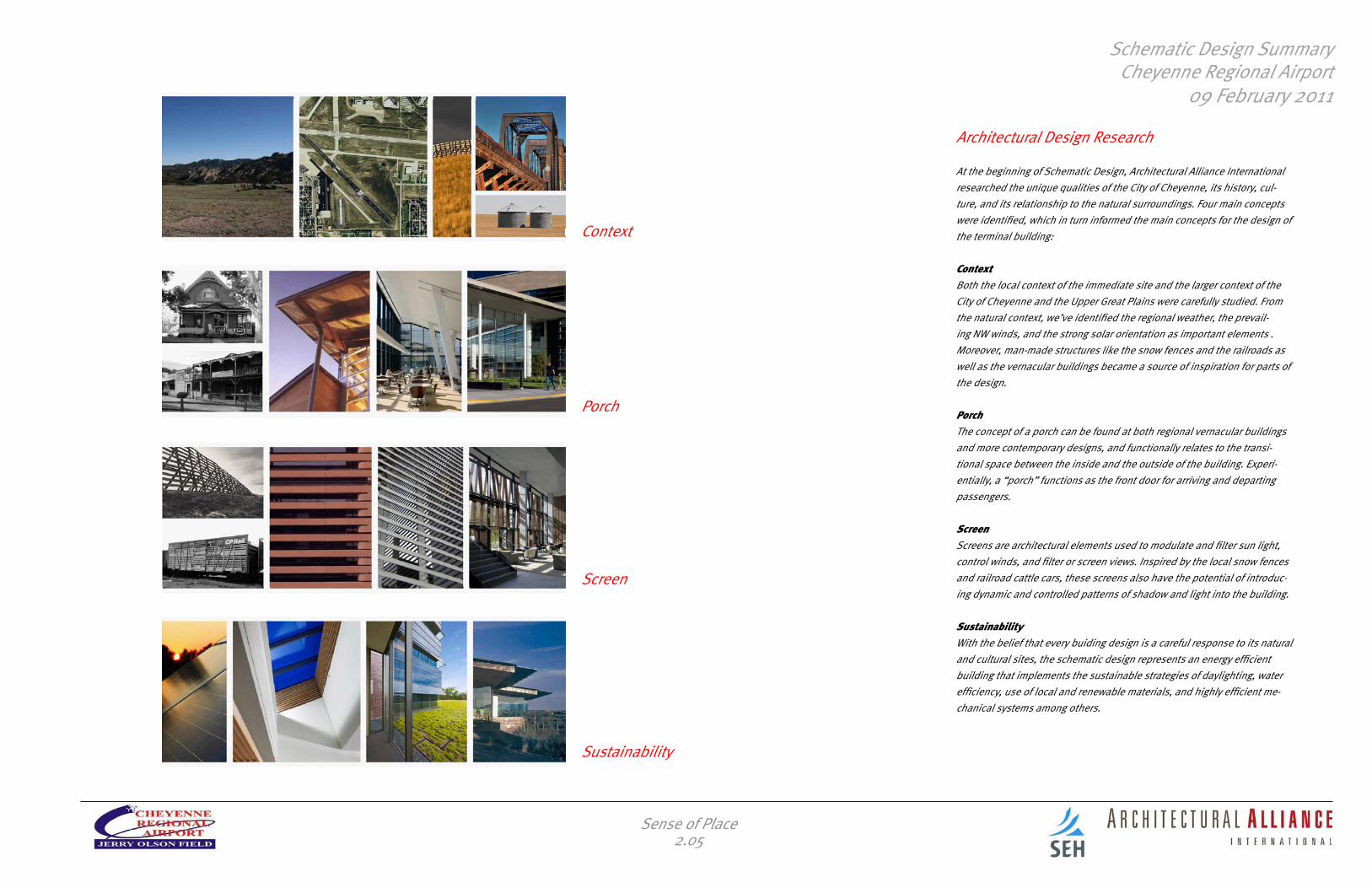
Architectural Design Research
At the beginning of Schematic Design, Architectural Alliance International researched the unique qualities of the City of Cheyenne, its history, cul-ture, and its relationship to the natural surroundings. Four main concepts were identified, which in turn informed the main concepts for the design of the terminal building: ContextBoth the local context of the immediate site and the larger context of the City of Cheyenne and the Upper Great Plains were carefully studied. From the natural context, we’ve identified the regional weather, the prevail-ing NW winds, and the strong solar orientation as important elements . Moreover, man-made structures like the snow fences and the railroads as well as the vernacular buildings became a source of inspiration for parts of the design.
PorchThe concept of a porch can be found at both regional vernacular buildings and more contemporary designs, and functionally relates to the transi-tional space between the inside and the outside of the building. Experi-entially, a “porch” functions as the front door for arriving and departing passengers.
ScreenScreens are architectural elements used to modulate and filter sun light, control winds, and filter or screen views. Inspired by the local snow fences and railroad cattle cars, these screens also have the potential of introduc-ing dynamic and controlled patterns of shadow and light into the building.
SustainabilityWith the belief that every buiding design is a careful response to its natural and cultural sites, the schematic design represents an energy efficient building that implements the sustainable strategies of daylighting, water efficiency, use of local and renewable materials, and highly efficient me-chanical systems among others.
Context
Porch
Screen
Sustainability
Sense of Place2.05

Schematic Design SummaryCheyenne Regional Airport
09 February 2011
3. Design Process
Design Process3.00

Schematic Design SummaryCheyenne Regional Airport
09 February 2011
Program Refinement
During the course of the workshops with Airport Staff and the Airport Board, a number of changes were made to programming assumptions developed during the 2008 Feasibility Study. These changes were driven by changes in current conditions and reassessments of previous decisions. Among the critical changes that impacted the Schematic Design:
Restaurant Size, Location, and Scope The Feasibility Study assumed a large, signature restaurant and bar lo-cated on the second floor of the terminal that would be directed primarily at Cheyenne residents rather than passengers. Based on the financial difficulties of the existing restaurant at the current terminal, the recent expansion of restaurant offerings within Cheyenne, and the significant in-vestment involved in a large restaurant, the Board ultimately decided that a smaller restaurant with more limited offerings, located to serve primarily passengers would be more appropriate.
Multi-story BuildingThe Level Two program in the Conceptual Design was dominated by the restaurant component, and when this was relocated, there was a question as to whether or not the building should remain a multi-story building. The Board determined that the multi-story building was still justified because the cost difference was determined to be insignificant, the second story gave the building additional presence on the site, it programmatically made sense to separate the administrative functions, and because of the efficiencies allowed by the partial basement.
Gate Hold and SecurityThe Gate Hold area was increased from a capacity of 60 in the Feasibility Study to 120 in Schematic Design to allow it to accommodate two simul-taneous regional jet departures (the ability to accommodate narrow-body jets and to handle diverted planes from Denver was also a factor in this decision). The Security Checkpoint was enlarged to allow it to accommo-date the latest TSA requirements.
Additional Concession SpaceThe Board directed that additional concession space (beyond the restau-rant) should be included as part of the Schematic Design. These tenant spaces may not be strictly driven by passenger traffic, so the spaces were located at the east end of the terminal, where they are adjacent to the short term parking lot. This location also allows for the spaces to be easily repurposed for future terminal expansion. Further, this location would allow the concession space to be modified or eliminated during future design phases without significantly impacting the terminal layout. The current layout shows three spaces totaling approximately 500 sf each, capable of accommodating office or small retail tenants.
Airline Ticket OfficesBased on the success of the recently instituted American Eagle service to DFW, the Board directed that the Schematic Design should accommodate three full Airline Ticket Offices in addition to a dedicated TSA space. The Conceptual Design had shown TSA occupying a future ATO space, but this would have required TSA to relocate should a third Airline be recruited, and left no swing space for charter operations.
Design Process3.01

Schematic Design SummaryCheyenne Regional Airport
09 February 2011
Workshop 1
Workshop 1 was held on 27 September 2010 at the offices of the Cheyenne Regional Airport. Present were representatives of Architectural Alliance International, SEH, Airport Director David Haring, and Airport Staff. The Feasibility Study was validated, especially relative to changes in airport operations driven by the addition of American Eagle service and the closure of the existing restaurant.
The design process was explained, and examples of previous projects were shown.
Results of initial Sense of Place and Architectural Design Research were presented.
Sustainability was identified as an important consideration, especially to the extent that careful building design, orientation, and selection of appropriate building systems could reduce long-term operating costs.
Design Process3.02

Schematic Design SummaryCheyenne Regional Airport
09 February 2011
Four plans were presented that demonstrated options for the restaurant within the new terminal.
Schemes 1A and 1B are both one level schemes. Scheme 1A locates the restaurant adjacent to the Gate Hold for easy passenger access. Scheme 1B locates the restaurant to the west, for adjacencies to the Loading Dock and Short Term Parking and ease of after-hours access.
Design Process3.03
Floor Plan Scheme 1B
Floor Plan Scheme 1A
Workshop 2
Workshop 2 was held on 10 November 2010 at the offices of the Cheyenne Regional Airport as a part of the regularly scheduled Airport Board meeting. Present were representatives of Architectural Alliance International, SEH, Airport Director David Haring, and the Airport Board.
The Sense of Place and Architectural Design Research was presented to the Airport Board.
Schematic Design SummaryCheyenne Regional Airport
09 February 2011
Design Process3.04
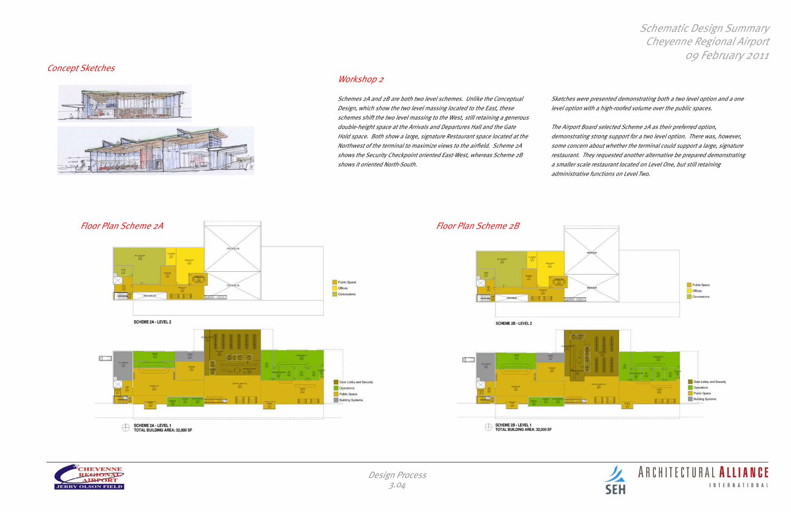
Sketches were presented demonstrating both a two level option and a one level option with a high-roofed volume over the public spaces.
The Airport Board selected Scheme 2A as their preferred option, demonstrating strong support for a two level option. There was, however, some concern about whether the terminal could support a large, signature restaurant. They requested another alternative be prepared demonstrating a smaller scale restaurant located on Level One, but still retaining administrative functions on Level Two.
Concept Sketches
Floor Plan Scheme 2BFloor Plan Scheme 2A
Workshop 2
Schemes 2A and 2B are both two level schemes. Unlike the Conceptual Design, which show the two level massing located to the East, these schemes shift the two level massing to the West, still retaining a generous double-height space at the Arrivals and Departures Hall and the Gate Hold space. Both show a large, signature Restaurant space located at the Northwest of the terminal to maximize views to the airfield. Scheme 2A shows the Security Checkpoint oriented East-West, whereas Scheme 2B shows it oriented North-South.

Schematic Design SummaryCheyenne Regional Airport
09 February 2011
Design Process3.05
Scheme 2C is an alternative showing a smaller restaurant located immedi-ately to the west of the Gate Hold space, but still retaining an upper level for the administrative functions and public viewing space. Scheme 2C has the advantage of offering better service for passengers, while still main-taining strong views to the airfield.
Scheme 2C was ultimately selected by the Airport Board.
Workshop 3
Workshop 3 was held on 08 December 2010 at the offices of the Cheyenne Regional Airport as a part of the regularly scheduled Airport Board meet-ing. Present were representatives of Architectural Alliance International, SEH, Airport Director David Haring, and the Airport Board.
As requested by the Board at the previous workshop, two schemes were presented. Scheme 2A is a refinement of the preferred plan presented at the previous meeting with a large, signature restaurant located in the northwest corner of Level Two.
Floor Plan Scheme 2CFloor Plan Scheme 2A

Schematic Design SummaryCheyenne Regional Airport
09 February 2011
Workshop 3
Interior renderings were presented, showing how the public spaces of the terminal are impacted by the changes between the 2A and 2C schemes.
Design Process3.06
SCHEME 2CSCHEME 2A
SECTION
Schematic Design SummaryCheyenne Regional Airport
09 February 2011
Design Process3.07
Workshop 3
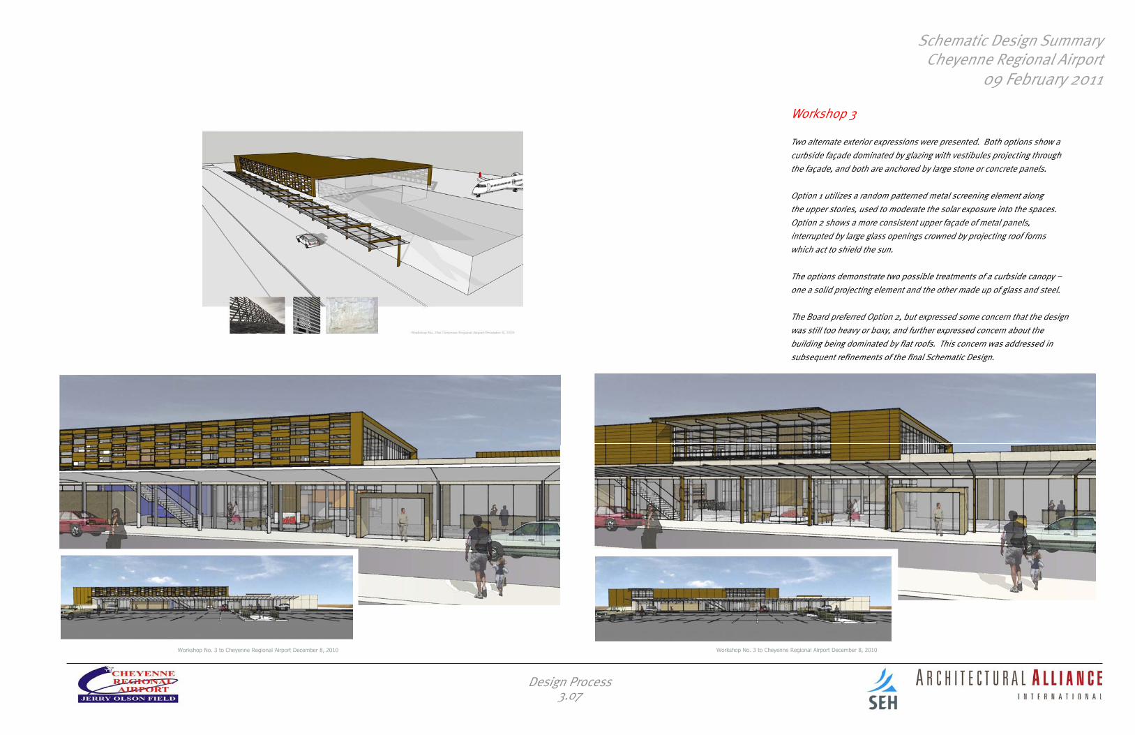
Two alternate exterior expressions were presented. Both options show a curbside façade dominated by glazing with vestibules projecting through the façade, and both are anchored by large stone or concrete panels.
Option 1 utilizes a random patterned metal screening element along the upper stories, used to moderate the solar exposure into the spaces. Option 2 shows a more consistent upper façade of metal panels, interrupted by large glass openings crowned by projecting roof forms which act to shield the sun.
The options demonstrate two possible treatments of a curbside canopy – one a solid projecting element and the other made up of glass and steel. The Board preferred Option 2, but expressed some concern that the design was still too heavy or boxy, and further expressed concern about the building being dominated by flat roofs. This concern was addressed in subsequent refinements of the final Schematic Design.

Schematic Design SummaryCheyenne Regional Airport
09 February 2011
4. Schematic Design
Schematic Design4.00

Schematic Design SummaryCheyenne Regional Airport
09 February 2011
UP
DN
UP
DN
2754 SF
Gate Ho ld44
1457 SF
Passeng er Scr een ing61
3307 SF
Departure / Arr ival Hall62
3116 SF
Bag gag e Cla im64
629 S
F
Depla
ning C
orrido
r65
Gate Lobby and Security
Operations
Public Space
Concessions
Building Systems
152 SF
Vestibule2
524 SF
Bag ga ge3
429 SF
Dock / Re ceiv ing9
152 SF
Vesti bule16
266 SF
Kitchen17
LEVEL 1
157 SF
Lob by21
68 SF
Vesti bule22
981 SF
Restau rant26
63 SF
Monitor31
69 SF
Scre ening32
109 SF
Ven ding33
73 SF
Vesti bule35 50 SF
Gate 141
50 SF
Gate 242
31 SF
Jan43
95 SF
Unisex50
305 SF
Me n51
305 SF
Wo me n52
160 SF
Rental Car53
160 SF
Rental Car55
161 SF
Rental Car59
160 SF
Rental Car66
0 32 48 64
322 SF
AT O68
322 SF
AT O69
322 SF
AT O70
323 SF
TSA Ba g Scre ening71
487 SF
TSA Off ice72
2128 SF
Bag ga ge Ma ke- Up73
2723 SF
Ticketin g Hall63
361 SF
Circ74
454 SF
Con ce ss io ns75
502 SF
Con ce ss io ns76
529 SF
Con ce ss io ns77
92 SF
Vesti bule79
54 SF
Toilet80
54 SF
Toilet81
41 SF
Jan82
JIHGFCBA K L M N O Q R S
4
55
6
2
33
0.9 11
D.5
1' -
6"27
' - 0
"28
' - 0
"10
' - 0
"20
' - 0
"10
' - 0
"
20' - 0" 20' - 0" 30' - 0" 30' - 0" 20' - 0" 20' - 0" 20' - 0" 20' - 0" 20' - 0" 20' - 0" 20' - 0" 20' - 0" 20' - 0" 30' - 0" 20' - 0" 20' - 0"
FUTUREGATEHOLDEXPANSION
FUTUREEXPANSION
1.8
32' -
0"
23' -
0"
30' -
0"
597 SF
Concession C irculat ion97
DN
DN
663 SF
Conf Ro om10
Public Space
Offices
Building Systems
708 SF
Upper Gal lery15
LEVEL 2
69 SF
Lob by23
230 SF
Stair 224
OP EN TO B E LOW
OP EN TO B E LOW641 SF
Break-Out36
R OOF
OP EN TO B E LOW
67 SF
Buffet84
83 SF
Toilet85
JIHGFCBA K L M N O Q R S
4
5
6
2
33
0.9 1
1
43 SF
Jan86
46 SF
Storage87
D.5
0 32 48 64
1' -
6"27
' - 0
"28
' - 0
"10
' - 0
"20
' - 0
"10
' - 0
"
20' - 0" 20' - 0" 30' - 0" 30' - 0" 20' - 0" 20' - 0" 20' - 0" 20' - 0" 20' - 0" 20' - 0"
187 SF
Kitchen88139 SF
Office89118 SF
Office90
118 SF
Office91
314 SF
Director92
157 SF
Admin S tor age93 582 SF
Reception / Circ94
72 SF
Intern95
64 SF
Cop y96
1.8
32' -
0"
23' -
0"
1095 SF
Circ99
UP
UP
1368 SF
Mecha nical Ro om37
Concessions
Building Systems
520 SF
Concess ion St ora ge38
1719 SF
Utility Tunnel39
LOWER LEVEL
1306 SF
Storm Ref uge83
JIHGFCBA K L M N O Q R S
4
55
6
2
33
0.9
1
0 32 48 64
D.5
1' -
6"27
' - 0
"28
' - 0
"10
' - 0
"20
' - 0
"10
' - 0
"
20' - 0" 20' - 0" 30' - 0" 30' - 0" 20' - 0" 20' - 0" 20' - 0" 20' - 0" 20' - 0" 20' - 0" 20' - 0" 20' - 0" 20' - 0" 30' - 0" 20' - 0" 20' - 0"
1.8
23' -
0"
30' -
0"
359 SF
Storage98
level 2
level 1
lower level
Plan Description
Level One, 25,300 sfThe Schematic Design proposes a facility with primary public and airport operations on the ground level, with public access from two entrances along the curbside (one at Ticketing and one at Bag Claim) and additional entrances from both the East and West Short Term Parking Lots. The Ticketing Hall, Arrivals and Departures Hall, and Bag Claim together form a generous public space that would be populated with welcoming soft seat-ing and a fireplace lounge for waiting passengers and the public.
In the Ticketing Hall, the facility is designed to accommodate three Airline Ticket Offices (ATO) with adjacent Baggage Make-Up spaces. There is dedicated space for Transportation Security Administration (TSA) of-fices. The Security Checkpoint is designed to accommodate the latest TSA requirements and to provide flexibility for future changes in security requirements. The Gate Hold contains seating for 120 and two departure gates with room for easy expansion to a third departure gate or the option to add a passenger boarding bridge. There is a fully separated Deplaning Corridor. The Bag Claim provides 50 linear feet of flat plate baggage claim area, with space to accommodate a future ‘T’ shaped device to provide additional capacity.
Located immediately adjacent to the Gate Hold, a Restaurant conces-sion space is open to the public but primarily oriented towards meeting the needs of flight passengers. The Restaurant and associated Kitchen totals 1250 sf. In addition to the Restaurant space, the Schematic Design accommodates three additional concession spaces at the east end of the terminal, totaling 1500 sf of leasable space and 600 sf of associated circulation space (this space is designed to be easily convertible to future Airline Ticket Offices should future passenger demand require it). There are also four Rental Car Offices provided, totaling 640 sf.
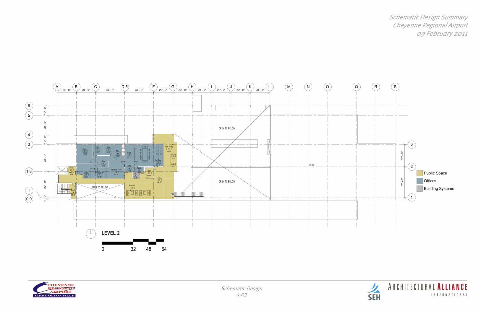
Level Two, 5,400 sfA second floor over the west portion of the building would be served by an elevator and provide administrative space and a large Conference Room capable of holding Airport Board meetings with public seating. There is an Upper Gallery providing views to the airfield and the Arrivals and Depar-tures Hall for the general public and a Breakout Space with soft seating. The Administration area contains four office spaces and support functions, including a Kitchen. The Kitchen, Upper Gallery, and Breakout Space can work in conjunction with the Conference Room to host public functions.
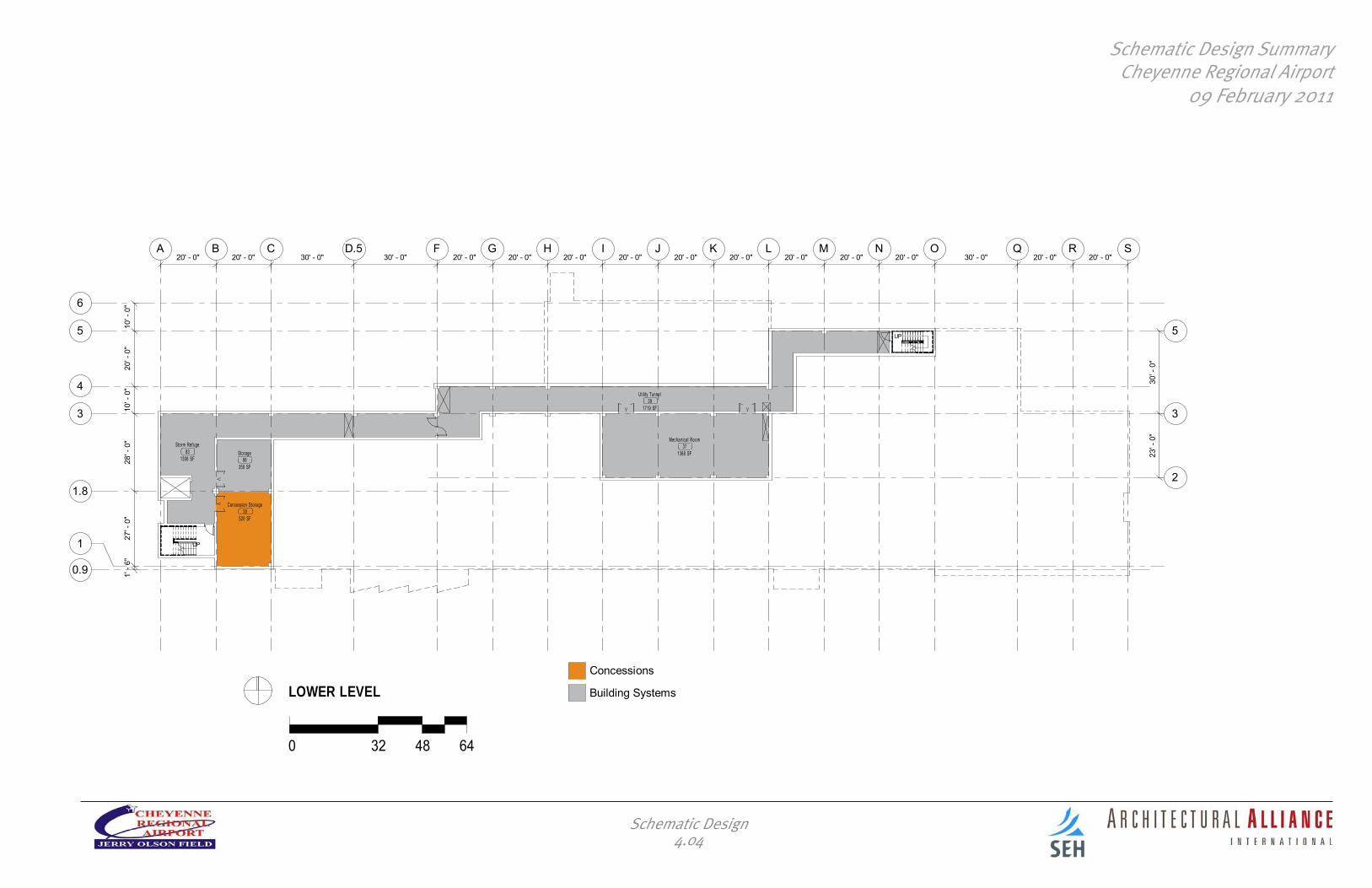
Lower Level, 5,300 sf A partial basement is designed for provision of Mechanical space and easy distribution to the upper floors through a Utility Tunnel. Storage space is provided both for the Airport and for concession users. Additional space is provided for storm refuge of up to 260 people. As the design progresses, the exact extents of the partial basement will need to be determined based on Mechanical and Storage needs (in concert with budget refinement).
Schematic Design4.01

Schematic Design SummaryCheyenne Regional Airport
09 February 2011
UP
DN
UP
DN
2754 SF
Gate Ho ld44
1457 SF
Passeng er Scr een ing61
3307 SF
Departure / Arr ival Hall62
3116 SF
Bag gag e Cla im64
629 S
F
Depla
ning C
orrido
r65
Gate Lobby and Security
Operations
Public Space
Concessions
Building Systems
152 SF
Vestibule2
524 SF
Bag ga ge3
429 SF
Dock / Re ceiv ing9
152 SF
Vesti bule16
266 SF
Kitchen17
LEVEL 1
157 SF
Lob by21
68 SF
Vesti bule22
981 SF
Restau rant26
63 SF
Monitor31
69 SF
Scre ening32
109 SF
Ven ding33
73 SF
Vesti bule35 50 SF
Gate 141
50 SF
Gate 242
31 SF
Jan43
95 SF
Unisex50
305 SF
Me n51
305 SF
Wo me n52
160 SF
Rental Car53
160 SF
Rental Car55
161 SF
Rental Car59
160 SF
Rental Car66
0 32 48 64
322 SF
AT O68
322 SF
AT O69
322 SF
AT O70
323 SF
TSA Ba g Scre ening71
487 SF
TSA Off ice72
2128 SF
Bag ga ge Ma ke- Up73
2723 SF
Ticketin g Hall63
361 SF
Circ74
454 SF
Con ce ss io ns75
502 SF
Con ce ss io ns76
529 SF
Con ce ss io ns77
92 SF
Vesti bule79
54 SF
Toilet80
54 SF
Toilet81
41 SF
Jan82
JIHGFCBA K L M N O Q R S
4
55
6
2
33
0.9 11
D.5
1' -
6"27
' - 0
"28
' - 0
"10
' - 0
"20
' - 0
"10
' - 0
"
20' - 0" 20' - 0" 30' - 0" 30' - 0" 20' - 0" 20' - 0" 20' - 0" 20' - 0" 20' - 0" 20' - 0" 20' - 0" 20' - 0" 20' - 0" 30' - 0" 20' - 0" 20' - 0"
FUTUREGATEHOLDEXPANSION
FUTUREEXPANSION
1.8
32' -
0"
23' -
0"
30' -
0"
597 SF
Concession C irculat ion97
Schematic Design4.02
Schematic Design SummaryCheyenne Regional Airport
09 February 2011
DN
DN
663 SF
Conf Ro om10
Public Space
Offices
Building Systems
708 SF
Upper Gal lery15
LEVEL 2
69 SF
Lob by23
230 SF
Stair 224
OP EN TO B E LOW
OP EN TO B E LOW641 SF
Break-Out36
R OOF
OP EN TO B E LOW
67 SF
Buffet84
83 SF
Toilet85
JIHGFCBA K L M N O Q R S
4
5
6
2
33
0.9 1
1
43 SF
Jan86
46 SF
Storage87
D.5
0 32 48 64
1' -
6"27
' - 0
"28
' - 0
"10
' - 0
"20
' - 0
"10
' - 0
"
20' - 0" 20' - 0" 30' - 0" 30' - 0" 20' - 0" 20' - 0" 20' - 0" 20' - 0" 20' - 0" 20' - 0"
187 SF
Kitchen88139 SF
Office89118 SF
Office90
118 SF
Office91
314 SF
Director92
157 SF
Admin S tor age93 582 SF
Reception / Circ94
72 SF
Intern95
64 SF
Cop y96
1.8
32' -
0"
23' -
0"
1095 SF
Circ99
Schematic Design4.03
Schematic Design SummaryCheyenne Regional Airport
09 February 2011
UP
UP
1368 SF
Mecha nical Ro om37
Concessions
Building Systems
520 SF
Concess ion St ora ge38
1719 SF
Utility Tunnel39
LOWER LEVEL
1306 SF
Storm Ref uge83
JIHGFCBA K L M N O Q R S
4
55
6
2
33
0.9
1
0 32 48 64
D.5
1' -
6"27
' - 0
"28
' - 0
"10
' - 0
"20
' - 0
"10
' - 0
"
20' - 0" 20' - 0" 30' - 0" 30' - 0" 20' - 0" 20' - 0" 20' - 0" 20' - 0" 20' - 0" 20' - 0" 20' - 0" 20' - 0" 20' - 0" 30' - 0" 20' - 0" 20' - 0"
1.8
23' -
0"
30' -
0"
359 SF
Storage98
Schematic Design4.04

Schematic Design SummaryCheyenne Regional Airport
09 February 2011
Schematic Design4.05
Operations
Baggage Make-Up Level 1 2128 SF
Baggage Level 1 524 SF
TSA Office Level 1 487 SF
Circ Level 1 361 SF
TSA Bag Screening Level 1 323 SF
ATO Level 1 322 SF
ATO Level 1 322 SF
ATO Level 1 322 SF
4790 SF
Public Space
Departure / Arrival Hall Level 1 3307 SF
Baggage Claim Level 1 3116 SF
Ticketing Hall Level 1 2723 SF
Circ Level 2 1095 SF
Upper Gallery Level 2 708 SF
Break-Out Level 2 641 SF
Concession Circulation Level 1 597 SF
Men Level 1 305 SF
Women Level 1 305 SF
Stair 1 Level 1 230 SF
Stair 2 Level 2 230 SF
Lobby Level 1 157 SF
Vestibule Level 1 152 SF
Vestibule Level 1 152 SF
Unisex Level 1 95 SF
Vestibule Level 1 92 SF
Toilet Level 2 83 SF
Lobby Level 2 69 SF
Vestibule Level 1 68 SF
14126 SF
35993 SF
Building Systems
Utility Tunnel Lower Level 1719 SF
Mechanical Room Lower Level 1368 SF
Storm Refuge Lower Level 1306 SF
Dock / Receiving Level 1 429 SF
Storage Lower Level 359 SF
Jan Level 2 43 SF
Jan Level 1 31 SF
5255 SF
Concessions
Restaurant Level 1 981 SF
Concessions Level 1 529 SF
Concession Storage Lower Level 520 SF
Concessions Level 1 502 SF
Concessions Level 1 454 SF
Kitchen Level 1 266 SF
Rental Car Level 1 161 SF
Rental Car Level 1 160 SF
Rental Car Level 1 160 SF
Rental Car Level 1 160 SF
3893 SF
Gate Lobby and Security
Gate Hold Level 1 2754 SF
Passenger Screening Level 1 1457 SF
Deplaning Corridor Level 1 629 SF
Vending Level 1 109 SF
Vestibule Level 1 73 SF
Screening Level 1 69 SF
Monitor Level 1 63 SF
Toilet Level 1 54 SF
Toilet Level 1 54 SF
Gate 1 Level 1 50 SF
Gate 2 Level 1 50 SF
Jan Level 1 41 SF
5403 SF
Offices
Conf Room Level 2 663 SF
Reception / Circ Level 2 582 SF
Director Level 2 314 SF
Kitchen Level 2 187 SF
Admin Storage Level 2 157 SF
Office Level 2 139 SF
Office Level 2 118 SF
Office Level 2 118 SF
Intern Level 2 72 SF
Buffet Level 2 67 SF
Copy Level 2 64 SF
Storage Level 2 46 SF
2526 SF
Room ScheduleRoom Schedule
Shows the Schematic Design building program broken out into the follow-ing departments:
Building Systems – Mechanical and building support spacesConcessions – Leasable spaces, including Restaurant, Rental Car Offices, and other Tenant SpacesGate Lobby and Security – Gate Hold, Security Checkpoint, and associated support spacesOffices – Administrative Offices, Conference Room, and support spacesOperations – Airline Ticket Offices, Baggage Make-Up, Baggage Claim, and support spacesPublic Space – Public gathering, circulation, and support spaces

Schematic Design SummaryCheyenne Regional Airport
09 February 2011
south elevation0 5 15 30 FT
west elevation0 5 15 30 FT
Building Elevations
The Schematic Design proposal orients the curbside façade to approxi-mately due south, aligning it with the runway beyond. This orientation allows for favorable solar access, bringing in south light which can be modulated by sunscreening elements and deep overhangs, allowing for more sun in the winter months when it is needed, and less in the summer months when it isn’t.
The south façade is grounded by light colored precast concrete panels at the east end. These are envisioned to relate to the tones of the light sand-stone that is found regionally, and will have texture and tones to enliven them. At the ground level, there will be extensive glazing that is shielded by the deep roadside canopy. The glazing will be penetrated by the two vestibules and the rental car offices, which are envisioned to be clad in wood on both the interior and exterior.
The building massing steps up to its multi-story massing, and at the far west end is terminated by the stair and elevator tower, which is again clad in the precast concrete panels.
Schematic Design4.06

Schematic Design SummaryCheyenne Regional Airport
09 February 2011
north elevation0 5 15 30 FT
east elevation0 5 15 30 FT
Building Elevations
The upper story of the terminal is clad in a mix of copper metal panels and in select locations, large expanses of glazing that bring daylighting deep into the space. These windows will be carefully located to take advantage of views, and will be treated with sunscreening elements as their exposure requires. Windows on the building’s north façade are able to bring in daylight without concern about heat gain or glare.
The precast panels and metal panels wrap the more utilitarian portions of the terminal’s airside, but the Gate Hold, Restaurant, and Upper Gallery all have expansive views out to the airside and are treated with glazing and articulated copper panels.
Schematic Design4.07
Schematic Design SummaryCheyenne Regional Airport
09 February 2011
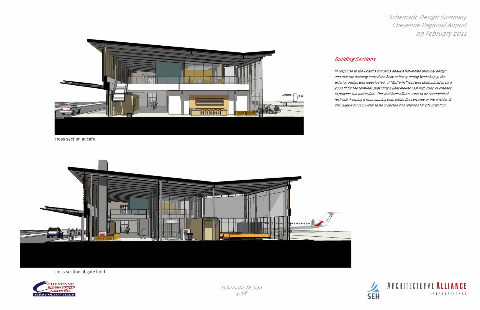
cross section at cafe
cross section at gate hold
Building Sections
In response to the Board’s concerns about a flat-roofed terminal design and that the building looked too boxy or heavy during Workshop 3, the exterior design was reevaluated. A “Butterfly” roof was determined to be a good fit for the terminal, providing a light feeling roof with deep overhangs to provide sun protection. This roof form allows water to be controlled ef-fectively, keeping it from running onto either the curbside or the airside. It also allows for rain water to be collected and retained for site irrigation.
Schematic Design4.08

Schematic Design SummaryCheyenne Regional Airport
09 February 2011
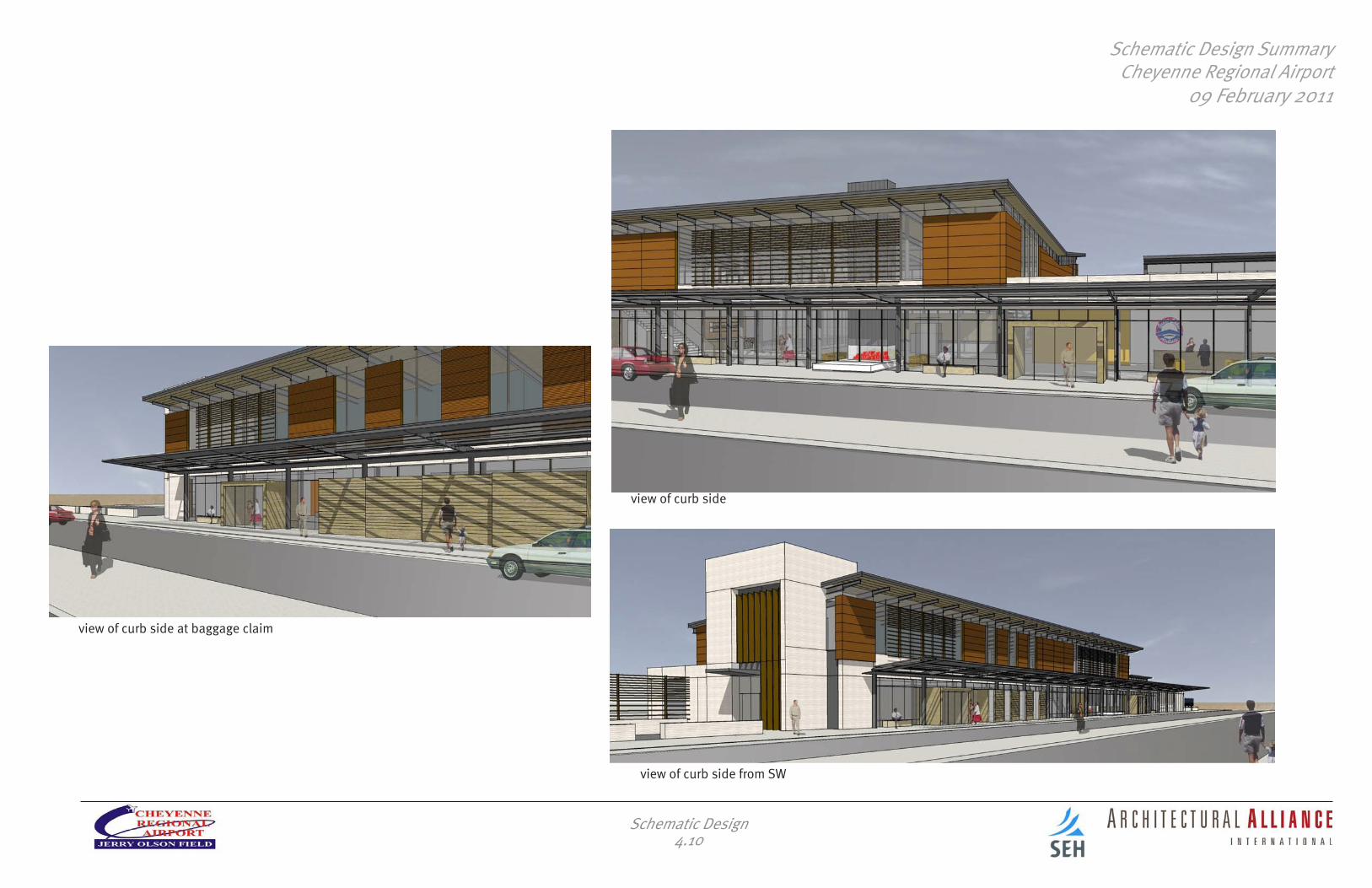
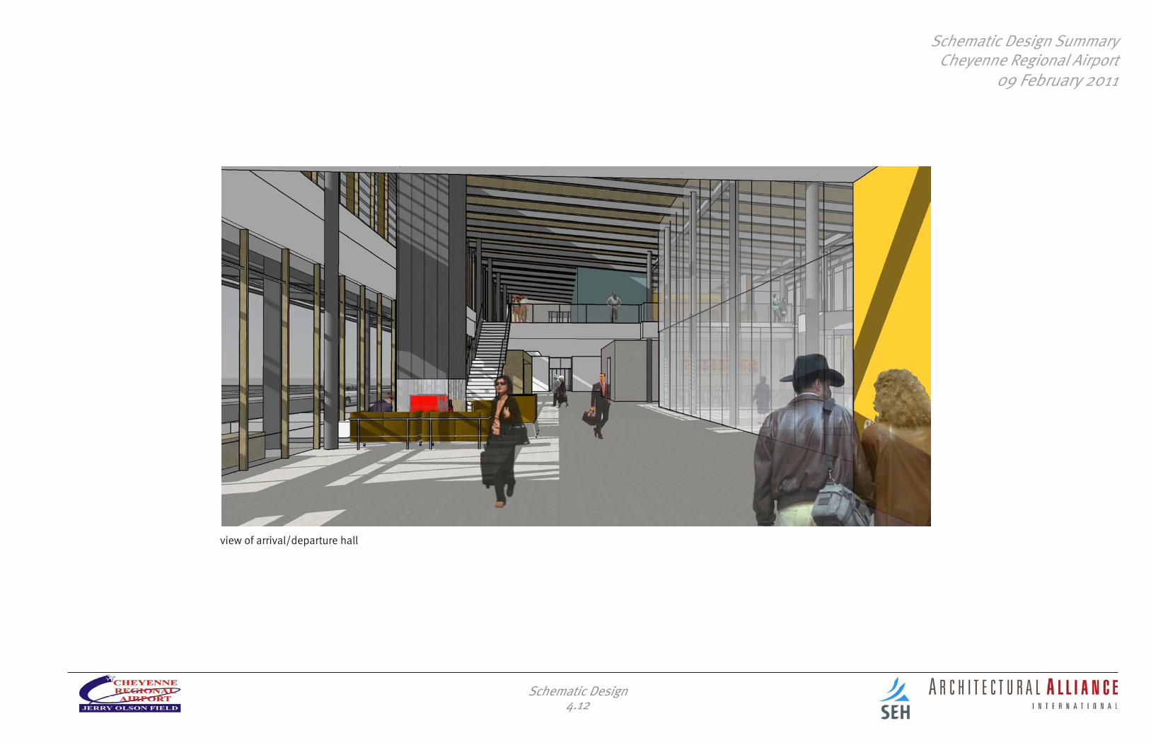
Building Renderings
A continuous clerestory window immediately below the deep overhang makes the roof appear to float over the building. The continuous glaz-ing at the curbside makes for an easy transition between the interior and the exterior spaces, with the fireplace visible and inviting. A smaller light monitor over the ticketing hall brings sunlight into these spaces.
view of terminal from parking
Schematic Design4.09
view of terminal from access road
Schematic Design SummaryCheyenne Regional Airport
09 February 2011
view of curb side at baggage claim
view of curb side from SW
Schematic Design4.10
view of curb side

Schematic Design SummaryCheyenne Regional Airport
09 February 2011
view of gate hold from NE
view of gate hold from NW
Schematic Design4.11
Schematic Design SummaryCheyenne Regional Airport
09 February 2011
view of arrival/departure hall
Schematic Design4.12

Schematic Design SummaryCheyenne Regional Airport
09 February 2011
Interior Material and Color Concept A
Schematic Design4.13
Interior Material and Color Concept B

Schematic Design SummaryCheyenne Regional Airport
09 February 2011
Schematic Design4.14
Concrete Floor Pattern

Schematic Design SummaryCheyenne Regional Airport
09 February 2011
5. Site Design
Site Design5.00