Scenarios Specification Report v3.2 -...
127
Scenarios Specification Report 6 April 2006 Advantech Satellite Networks Proprietary Page 1/131 ESA Contract no. 19549/05/NL/AD Study of DVB-S(2)/DVB-RCS Broadband Mobile System Scenarios Specification Report
Transcript of Scenarios Specification Report v3.2 -...
Scenarios Specification Report
6 April 2006 Advantech Satellite Networks Proprietary Page 1/131
ESA Contract no. 19549/05/NL/AD
Study of DVB-S(2)/DVB-RCS Broadband Mobile System
Scenarios Specification Report
Scenarios Specification Report
6 April 2006 Advantech Satellite Networks Proprietary Page 2/131
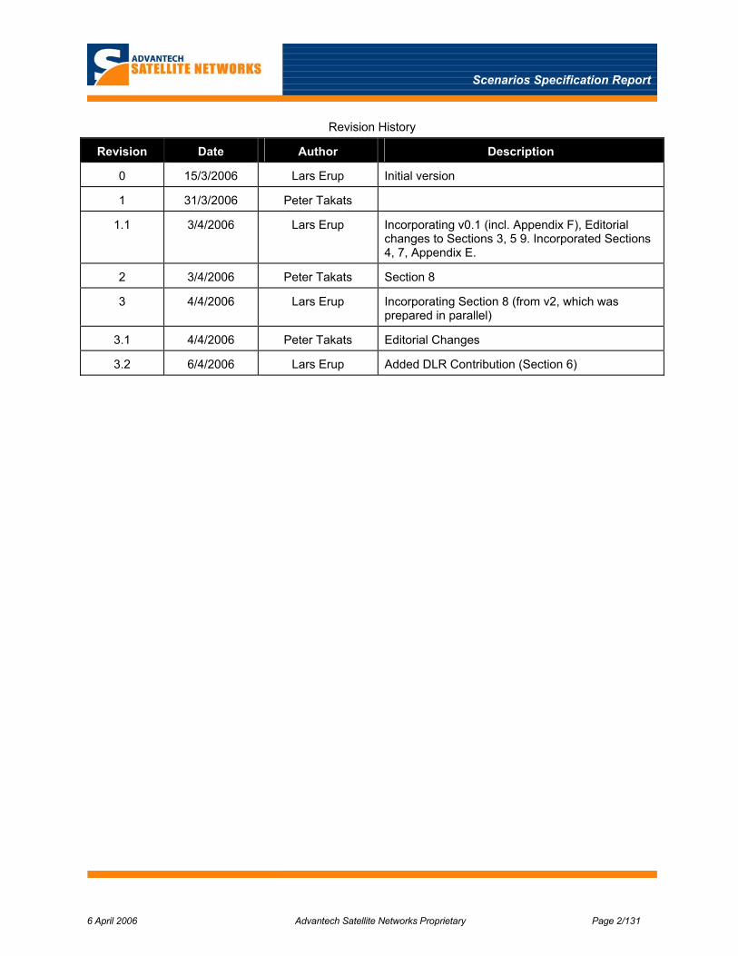
Revision History
Revision Date Author Description
0 15/3/2006 Lars Erup Initial version
1 31/3/2006 Peter Takats
1.1 3/4/2006 Lars Erup Incorporating v0.1 (incl. Appendix F), Editorial changes to Sections 3, 5 9. Incorporated Sections 4, 7, Appendix E.
2 3/4/2006 Peter Takats Section 8
3 4/4/2006 Lars Erup Incorporating Section 8 (from v2, which was prepared in parallel)
3.1 4/4/2006 Peter Takats Editorial Changes
3.2 6/4/2006 Lars Erup Added DLR Contribution (Section 6)

Scenarios Specification Report
6 April 2006 Advantech Satellite Networks Proprietary Page 3/131
Table of Contents 1 INTRODUCTION ................................................................................................................................................ 9
1.1 OBJECTIVES AND SCOPE .................................................................................................................................. 9 1.2 ORGANISATION OF THE REPORT ...................................................................................................................... 9 1.3 CONTRIBUTORS ............................................................................................................................................... 9
2 REFERENCES ................................................................................................................................................... 10
3 REVIEW OF PREVIOUS RESULTS .............................................................................................................. 14 3.1 PREVIOUS STUDIES ........................................................................................................................................ 14
3.1.1 ITU-R Resolution 216 Studies............................................................................................................... 14 3.1.2 ESA WeB Mobility Study....................................................................................................................... 14 3.1.3 Mowgly ................................................................................................................................................. 15
3.2 TRIAL SYSTEMS............................................................................................................................................. 15 3.2.1 FIFTH................................................................................................................................................... 15 3.2.2 21 NET.................................................................................................................................................. 17
3.3 COMMERCIAL SYSTEMS ................................................................................................................................ 17 3.3.1 Aeronautical ......................................................................................................................................... 18 3.3.2 Maritime ............................................................................................................................................... 20 3.3.3 Land...................................................................................................................................................... 21
3.4 COMMERCIAL EQUIPMENT ............................................................................................................................ 21 3.4.1 ODUs /Antenna systems........................................................................................................................ 22
4 APPLICATIONS AND MARKETS ................................................................................................................. 24 4.1 AERONAUTICAL............................................................................................................................................. 25 4.2 MARITIME ..................................................................................................................................................... 29 4.3 LAND MOBILE ............................................................................................................................................... 31
4.3.1 Trains.................................................................................................................................................... 31 4.3.2 Buses..................................................................................................................................................... 34 4.3.3 Caravan /Cars ...................................................................................................................................... 35
5 REGULATORY ENVIRONMENT.................................................................................................................. 36 5.1 RADIO TRANSMISSION REGULATIONS ........................................................................................................... 36
5.1.1 Frequency Allocations .......................................................................................................................... 36 5.1.2 MSS Standards and Recommendations................................................................................................. 39
5.2 APPLICATION-SPECIFIC INTERFERENCE ENVIRONMENTS .............................................................................. 44 5.2.1 Aeronautical ......................................................................................................................................... 44 5.2.2 Maritime ............................................................................................................................................... 51 5.2.3 Land Mobile.......................................................................................................................................... 51
5.3 TERRESTRIAL GAPFILLER REGULATORY ENVIRONMENT............................................................................... 51 5.4 INTERFERENCE MITIGATION TECHNIQUES..................................................................................................... 53
5.4.1 FSS Interference Mitigation.................................................................................................................. 53 5.4.2 Terrestrial / Other Interference Mitigation .......................................................................................... 53
5.5 OTHER REGULATORY ISSUES ........................................................................................................................ 53 5.5.1 Aeronautical ......................................................................................................................................... 54 5.5.2 Maritime ............................................................................................................................................... 54 5.5.3 Land...................................................................................................................................................... 54
6 CHANNEL MODELS........................................................................................................................................ 55 6.1 BRIEF REVIEW OF NON FREQUENCY SELECTIVE SINGLE AND MULTI STATE CHANNEL MODELS ................. 55 6.2 THE LAND VEHICULAR ENVIRONMENT ......................................................................................................... 57

Scenarios Specification Report
6 April 2006 Advantech Satellite Networks Proprietary Page 4/131
6.2.1 Ku Band 3 States Land Vehicular Channel Model ............................................................................... 57 6.2.2 Ka Band 3 States Land Vehicular Channel Model ............................................................................... 59 6.2.3 A Comparison of the 1st and 2nd Order Statistics Obtained by the Above Models ................................ 61 6.2.4 Extension to the Railway Case.............................................................................................................. 61
6.3 THE AERONAUTICAL ENVIRONMENT............................................................................................................. 63 6.3.1 Taxiway, Cruising, Ascent and Descent Flight Phases......................................................................... 63 6.3.2 Extreme Manoeuvres ............................................................................................................................ 63
6.4 THE MARITIME ENVIRONMENT ..................................................................................................................... 64 6.5 DOPPLER SHIFT AND DOPPLER SPREAD ESTIMATION .................................................................................... 66 6.6 OTHER RELEVANT FADING SOURCES (NOT DUE TO MOBILITY)..................................................................... 67
6.6.1 Rain Attenuation for Aircrafts .............................................................................................................. 68 6.7 SUMMARY OF THE RELEVANT IMPAIRMENTS SOURCES FOR EACH ENVIRONMENT........................................ 69
7 TRAFFIC MODELS .......................................................................................................................................... 71 7.1 WEB TRAFFIC MODEL ................................................................................................................................... 71 7.2 FTP TRAFFIC MODEL .................................................................................................................................... 73 7.3 VIDEO STREAMING MODEL ........................................................................................................................... 73 7.4 VOIP MODEL................................................................................................................................................. 74 7.5 AGGREGATE LAN TRAFFIC........................................................................................................................... 75
8 SATELLITE SYSTEM CHARACTERISTICS............................................................................................... 76 8.1 SYSTEM ARCHITECTURE SCENARIOS............................................................................................................. 76
8.1.1 FSS Scenarios ....................................................................................................................................... 77 8.1.2 BSS Scenario......................................................................................................................................... 80
8.2 SPACE SEGMENT............................................................................................................................................ 82 9 TERMINAL CHARACTERISTICS................................................................................................................. 83
9.1 OVERVIEW..................................................................................................................................................... 83 9.1.1 Indoor Unit ........................................................................................................................................... 84 9.1.2 Outdoor Unit......................................................................................................................................... 84
9.2 AERONAUTICAL............................................................................................................................................. 86 9.3 MARITIME ..................................................................................................................................................... 87 9.4 LAND............................................................................................................................................................. 87
10 TERRESTRIAL WIRELESS NETWORKS................................................................................................ 88 10.1 OVERVIEW OF TERRESTRIAL TECHNOLOGIES................................................................................................ 88
10.1.1 Telecom-Based Networks...................................................................................................................... 89 10.1.2 Broadcast Based Networks ................................................................................................................... 92 10.1.3 Summary of Terrestrial Network Characteristics ................................................................................. 92 10.1.4 Convergence ......................................................................................................................................... 93
10.2 COMPETITION FROM TERRESTRIAL NETWORKS............................................................................................. 94 10.2.1 Aeronautical ......................................................................................................................................... 94 10.2.2 Maritime ............................................................................................................................................... 94 10.2.3 Land Mobile.......................................................................................................................................... 95 10.2.4 Summary ............................................................................................................................................... 96
11 TERRESTRIAL GAP FILLERS .................................................................................................................. 97 11.1 TYPE 1 — INTEGRAL GAPFILLER................................................................................................................... 97
11.1.1 Forward Link ........................................................................................................................................ 98 11.1.2 Return Link ......................................................................................................................................... 100 11.1.3 Synchronisation Issues........................................................................................................................ 102
11.2 TYPE 2 — TERRESTRIAL GAPFILLER ........................................................................................................... 104 11.3 TYPE 3 — HYBRID GAPFILLER .................................................................................................................... 105 11.4 SUMMARY ................................................................................................................................................... 106

Scenarios Specification Report
6 April 2006 Advantech Satellite Networks Proprietary Page 5/131
12 PRELIMINARY AIR INTERFACE CONSIDERATIONS ..................................................................... 107 12.1 SATELLITE AIR INTERFACE.......................................................................................................................... 107
12.1.1 Forward Link ...................................................................................................................................... 107 12.1.2 Return Link ......................................................................................................................................... 107
12.2 GAP FILLER AIR INTERFACE........................................................................................................................ 108 12.2.1 Forward Link ...................................................................................................................................... 108 12.2.2 Return Link ......................................................................................................................................... 108
13 SUMMARY AND RECOMMENDATIONS.............................................................................................. 110
14 APPENDIX A: SOME FEATURES OF DVB-BASED TERRESTRIAL STANDARDS ...................... 111
15 APPENDIX B: EXAMPLE HETEROGENEOUS NETWORK ARCHITECTURE............................. 114 15.1 SUMMARY OF MOBY DICK .......................................................................................................................... 114 15.2 MOBILITY MANAGEMENT ........................................................................................................................... 115 15.3 QOS AND AAA............................................................................................................................................ 115 15.4 REFERENCES................................................................................................................................................ 115
16 APPENDIX C: GAPFILLER SIGNAL LEVEL DYNAMICS................................................................. 116
17 APPENDIX D: FORWARD LINK SYNCHRONISATION MAINTENANCE ..................................... 118 17.1 PREVENTING THE IMMEDIATE IMPACT OF THE PCR DISCONTINUITY ........................................................... 119 17.2 DETERMINATION OF THE DELTA CORRECTION ............................................................................................ 119
17.2.1 Hub Side Determination ..................................................................................................................... 119 17.2.2 Terminal Side Determination.............................................................................................................. 119
17.3 PROPOSED PCR LOOP MODIFICATION......................................................................................................... 120 17.4 PROPOSED PROCESS .................................................................................................................................... 120
18 APPENDIX E: AERONAUTICAL BROADBAND SYSTEMS............................................................... 122
19 APPENDIX F: INITIAL SPREAD SPECTRUM SYSTEM..................................................................... 124 19.1 FORWARD LINK........................................................................................................................................... 124 19.2 RETURN LINK .............................................................................................................................................. 126
19.2.1 Basic Operation .................................................................................................................................. 126 19.2.2 Synchronisation and Code-Matched Filters ....................................................................................... 127 19.2.3 Choice of Spreading Sequence............................................................................................................ 128
19.3 AIR INTERFACE SUMMARY.......................................................................................................................... 129 19.3.1 Forward Link ...................................................................................................................................... 129 19.3.2 Return Link ......................................................................................................................................... 130
19.4 REFERENCES................................................................................................................................................ 131
Scenarios Specification Report
6 April 2006 Advantech Satellite Networks Proprietary Page 6/131
List of Figures
FIGURE 3-1: FIFTH SYSTEM ARCHITECTURE................................................................................................................ 16 FIGURE 3-2: 21 NET SYSTEM ARCHITECTURE .............................................................................................................. 17 FIGURE 3-3: CONNEXION FORWARD LINK ARCHITECTURE ........................................................................................... 19 FIGURE 3-4: CONNEXION RETURN LINK ARCHITECTURE .............................................................................................. 19 FIGURE 4-1 AERONAUTICAL SEGMENT (FROM MOWGLY [40]) ...................................................................................... 26 FIGURE 4-2: MARITIME SEGMENT (FROM MOWGLY [40]) .......................................................................................... 30 FIGURE 4-3: TERRESTRIAL SEGMENT (FROM MOWGLY [40])...................................................................................... 32 FIGURE 5-1: DOWNLINK EIRP DENSITY MASK.............................................................................................................. 41 FIGURE 5-2: OFF-AXIS EIRP DENSITY VERSUS EIRP MASK (3 DEGREE SPACING) ......................................................... 45 FIGURE 5-3: FS INTERFERENCE GEOMETRY .................................................................................................................. 46 FIGURE 5-4: AES EIRP MASK FOR FS INTERFERENCE SCENARIO................................................................................. 47 FIGURE 5-5: AES EIRP MASK FOR RAS INTERFERENCE SCENARIO ............................................................................. 48 FIGURE 5-6: EIRP MASK FOR SRS................................................................................................................................ 50 FIGURE 6-1: RURAL ENVIRONMENT WEST OF MUNICH: OPEN (LEFT), TREE ALLEY (MID) AND PINE FOREST (RIGHT) ..... 57 FIGURE 6-2: SUB-URBAN (LEFT), URBAN (MID) AND HIGHWAY (RIGHT) ENVIRONMENTS IN AND AROUND MUNICH ...... 58 FIGURE 6-3: COMPLEMENTARY CDFS FOR THE LMSC AT KU, KA AND EHF BANDS TAKEN FROM [53] ....................... 61 FIGURE 6-4: NOMENCLATURE OF RAILWAY SPECIFIC OBSTACLES (LEFT) AND GEOMETRY OF THE KNIFE-EDGE
DIFFRACTION APPLIED TO ELECTRICAL TRELLISES (RIGHT).................................................................................... 62 FIGURE 6-5: MEASURED ATTENUATION IN DECIBELS PRODUCED BY ELECTRICAL TRELLISES (LEFT), ELECTRICAL POSTS
WITH BRACKETS (MID) AND CATENARIES (RIGHT) AT KU-BAND [54]..................................................................... 62 FIGURE 6-6: RECEIVED POWER DURING CRUISING (LEFT) AND CORRESPONDING RICEAN PDF (RIGHT) [56] ................. 63 FIGURE 6-7: SIGNAL FADES PROVOKED BY THE AIRCRAFT STRUCTURE (WING) DURING EXTREME MANOUVERS [56].... 64 FIGURE 6-8: SIGNAL FADES AND AIRCRAFT ALTITUDE DURING MEANDER MANOUVERS [56]......................................... 64 FIGURE 6-9: AMPLITUDE OF 3RD FRESNEL ZONE NEAR THE MOBILE TERMINAL .............................................................. 65 FIGURE 6-10: FRESNEL ELLIPSOID ................................................................................................................................. 65 FIGURE 6-11: POSITION OF TERMINAL AND SATELLITE RELATIVE TO EARTH ................................................................. 66 FIGURE 6-12: GLOBAL MEAN RAIN HEIGHT Rh ABOVE MEAN SEA LEVEL (BASED ON DATA AVAILABLE ON
ITU/DATABANKS-TROPO, 2005) ............................................................................................................................ 69 FIGURE 7-1: SOURCE TRAFFIC MODELLING APPROACH.................................................................................................. 71 FIGURE 7-2: VIDEO STREAMING MODEL......................................................................................................................... 74 FIGURE 7-3: VOICE TRAFFIC MODEL.............................................................................................................................. 75 FIGURE 8-1: SATELLITE BROADBAND MOBILE SYSTEM ARCHITECTURE – FSS TYPE ................................................... 77 FIGURE 8-2: ANIKF1 KU BAND AREA BEAM COVERAGE .............................................................................................. 78 FIGURE 8-3: ANIKF2 KA BAND SPOT BEAM COVERAGE................................................................................................. 78 FIGURE 8-4: TELSTAR 14 (ESTRELA DO SUL) COVERAGE IN KU-BAND.......................................................................... 79 FIGURE 8-5: CONNEXION BY BOEING PLANNED COVERAGE FOR FULL NETWORK EXPANSION [2]............................... 79 FIGURE 8-6: SATELLITE BROADBAND MOBILE SYSTEM ARCHITECTURE – BSS TYPE................................................... 80 FIGURE 8-7: ECHOSTAR 8 MULTIBEAM COVERAGE FOR LOCAL PROGRAMMING............................................................. 81 FIGURE 9-1: MOBILE TERMINAL RF CONFIGURATION FOR LOW PROFILE ANTENNA .................................................... 86 FIGURE 10-1: WIRELESS EVOLUTION ............................................................................................................................ 89 FIGURE 10-2: EXAMPLE 3G COVERAGE (ORANGE, UK). ............................................................................................... 91 FIGURE 11-1: CONCEPTUAL BLOCK DIAGRAM OF INTEGRAL GAP FILLER....................................................................... 98 FIGURE 11-2: EXAMPLE GAPFILLER ARRANGEMENT WITH PHYSICAL LAYER TRANSLATION........................................ 101 FIGURE 11-3: BASIC SYNCHRONISATION ISSUES WITH GAPFILLERS. ........................................................................... 103 FIGURE 11-4: INTERNETWORKING SCENARIO. ............................................................................................................. 105 FIGURE 14-1: TIME SLICE FEATURE OF DVB-H........................................................................................................... 111 FIGURE 14-2: COMPARISON OF CODING IN DVB-H, DVB-T, DAB AND DMB............................................................ 111 FIGURE 14-3: MPE-FEC ORGANISATION .................................................................................................................... 112 FIGURE 14-4: APPLICATION LAYER DATAGRAM ORGANISATION FOR MPE-FEC........................................................ 112
Scenarios Specification Report
6 April 2006 Advantech Satellite Networks Proprietary Page 7/131
FIGURE 15-1: MOBY DICK ARCHITECTURE.................................................................................................................. 114 FIGURE 16-1: GAPFILLER GEOMETRY. ......................................................................................................................... 116 FIGURE 16-2: PATH LOSS VARIATION IN FIRST SECOND AFTER PASSING GAPFILLER..................................................... 116 FIGURE 17-1: SYSTEMS LEVEL DIAGRAM OF CURRENT PCR RECOVERY METHOD........................................................ 118 FIGURE 17-2: CONCEPT OF INCLUDING A DELTA CORRECTION IN THE LOCAL PCR ERROR FEEDBACK LOOP................ 119 FIGURE 17-3: PROPOSED MODIFICATIONS TO THE PCR LOOP. .................................................................................... 120 FIGURE 17-4: PROPOSED SEQUENCE OF EVENTS SURROUNDING A SWITCHOVER........................................................ 121 FIGURE 18-1: GENERAL CARRIER-PAIRING CONFIGURATION....................................................................................... 122 FIGURE 18-2: GW PROCESSING WITH INTERFERENCE CANCELLATION ....................................................................... 123 FIGURE 19-1: CONCEPTUAL BLOCK DIAGRAM OF FORWARD SPREAD-SPECTRUM MODULATOR. .................................. 125 FIGURE 19-2: DIGITAL DELAY-LOCK LOOP AND DESPREADING ................................................................................. 125 FIGURE 19-3: CONCEPTUAL BLOCK DIAGRAM OF TERMINAL MODULATOR .................................................................. 126 FIGURE 19-4: CONCEPTUAL BLOCK DIAGRAM OF RLSS DEMODULATOR..................................................................... 127 FIGURE 19-5: CODE MATCHED FILTER CORRELATOR. .................................................................................................. 128

Scenarios Specification Report
6 April 2006 Advantech Satellite Networks Proprietary Page 8/131
List of Tables TABLE 3-1: SUMMARY OF KEY AERONAUTICAL MOBILE SERVICE PARAMETERS ......................................................... 18 TABLE 3-2: SUMMARY OF KEY LAND MOBILE SERVICE PARAMETERS ......................................................................... 21 TABLE 3-3: SURVEY OF MOBILE ANTENNA SYSTEM TECHNOLOGY. ............................................................................... 22 TABLE 4-1: APPLICATIONS FOR EACH TERMINAL (AERONAUTICAL). ............................................................................. 27 TABLE 4-2: ORDERS AND DELIVERIES PUBLISHED BY AIRBUS FOR EUROPE .................................................................. 28 TABLE 4-3: ORDERS AND DELIVERIES PUBLISHED BY AIRBUS FOR NORTH AMERICA.................................................... 28 TABLE 4-4: TOTAL REQUIRED THROUGHPUT FOR AERONAUTICAL MARKET .................................................................. 29 TABLE 4-5: APPLICATIONS FOR EACH TERMINAL (CRUISE SHIP) .................................................................................... 30 TABLE 4-6: TOTAL REQUIRED THROUGHPUT FOR MARITIME MARKET ........................................................................... 31 TABLE 4-7: APPLICATIONS FOR EACH TERMINAL: TRAINS............................................................................................. 33 TABLE 4-8: TOTAL REQUIRED THROUGHPUT FOR TRAIN MARKET.................................................................................. 34 TABLE 4-9: APPLICATIONS FOR EACH TERMINAL: BUSES .............................................................................................. 35 TABLE 5-1: ITU-R MOBILE SATELLITE SERVICE (MSS) ALLOCATIONS........................................................................ 36 TABLE 5-2: ITU FREQUENCY PLAN FOR KU BAND.......................................................................................................... 37 TABLE 5-3: ITU FREQUENCY PLAN FOR KA BAND .......................................................................................................... 38 TABLE 5-4: MSS STANDARDS AND RECOMMENDATIONS .............................................................................................. 39 TABLE 5-5: GEO FLUX DENSITY LIMIT IN 4KHZ............................................................................................................ 40 TABLE 5-6: FSS OFF-AXIS EIRP DENSITY MASK ......................................................................................................... 41 TABLE 5-7: FIXED SERVICE PFD LIMIT IN 1 MHZ ......................................................................................................... 43 TABLE 5-8: RADIO ASTRONOMY SERVICE PFD LIMIT IN 150 KHZ ................................................................................ 43 TABLE 5-9: ON-AXIS EIRP DENSITY ............................................................................................................................. 45 TABLE 5-10: AES-FS INTERFERENCE PATH ISOLATION FOR 12KM CRUISING ALTITUDE .............................................. 47 TABLE 5-11: AES-RAS INTERFERENCE PATH ISOLATION FOR 12KM CRUISING ALTITUDE ........................................... 49 TABLE 5-12: SRS PFD IN 4 KHZ ................................................................................................................................... 49 TABLE 5-13: AES-SRS INTERFERENCE PATH ISOLATION FOR 12KM CRUISING ALTITUDE............................................ 50 TABLE 5-14: WLAN FREQUENCY ALLOCATIONS ......................................................................................................... 52 TABLE 6-1: COHERENCE BANDWIDTH MEASUREMENTS WITH OMNIDIRECTIONAL ANTENNAS ...................................... 55 TABLE 6-2: KU-BAND LAND VEHICULAR CHANNEL MODEL PARAMETERS ..................................................................... 58 TABLE 6-3: LOO DISTRIBUTION PARAMETERS TAKEN FROM [52]................................................................................... 59 TABLE 6-4: KA-BAND LAND VEHICULAR CHANNEL MODEL STATE TRANSITION MATRIXES TAKEN FROM [52] ............. 60 TABLE 6-5: WORST-CASE DOPPLER FIGURES AT KU-BAND ........................................................................................... 67 TABLE 6-6: DOPPLER SPREAD AND COHERENCE TIME ESTIMATIONS ............................................................................ 67 TABLE 6-7: RELEVANT IMPAIRMENTS SOURCES FOR EACH ENVIRONMENT.................................................................... 70 TABLE 7-1: WEB SERVER MODEL PARAMETERS............................................................................................................. 72 TABLE 7-2: FTP MODEL PARAMETERS........................................................................................................................... 73 TABLE 7-3: VIDEO STREAMING MODEL PARAMETERS.................................................................................................... 74 TABLE 8-1: MOBILITY SYSTEM ARCHITECTURE SCENARIOS......................................................................................... 76 TABLE 8-2: SATELLITE AND TERMINAL BASELINE PERFORMANCE ................................................................................ 82 TABLE 9-1: IMPACTS ON MOBILE TERMINAL CHARACTERISATION ............................................................................... 83 TABLE 10-1: SUMMARY OF TERRESTRIAL TECHNOLOGIES............................................................................................. 93 TABLE 14-1: DVB-T SFN CELL RADIUS (8 MHZ CHANNEL) ...................................................................................... 113

Scenarios Specification Report
6 April 2006 Advantech Satellite Networks Proprietary Page 9/131
1 INTRODUCTION
1.1 Objectives and Scope
This document constitutes the deliverable of WP1.1.1 of ESA contract no. 19549/05/NL/AD. The objective of the present document is to define the system scenarios to be used for the further analysis in the study, in order to limit the envelope of the parameters to be investigated. The report brings together previous work in the area of mobile satellite broadband systems as well as some of the fundamental parameters that govern the intended applications; including applications and markets, traffic volumes and characteristics, physical constraints such as channel characteristics and regulatory constraints, as well as the expected competition and/or synergies with terrestrial alternatives.
From this database, overall system characteristics have been determined for a number of application scenarios. The report describes the space, ground and gapfiller segments, as well as a number of characteristics of the physical layer air interface, which is closely interlinked with the system architecture.
1.2 Organisation of the Report
The present report addresses a large number of highly interrelated topics. It is impossible to present this material in a linear fashion, without cross-references that point ahead to topics that are only addressed in detail in a subsequent chapter. We have however attempted to make the presentation as logical as possible. We begin with a review of previous work and other initiatives in the area of broadband mobile satellite systems (Section 3), and then present some of the "fundamentals": Applications and markets, the regulatory environment, and channel and traffic models (Sections 4–7). We then derive the overall characteristics of the ground and space segments of purely satellite-based systems (Sections 8 and 9).
The terrestrial component is introduced next. Section 10 provides a summary and outlook for terrestrial wireless networks and assessments of how these are threats or opportunities for our applications. Following on from this, the terrestrial gap-filler segment of the satellite network is presented in Section 11.
It turns out that there are many close ties between the system architecture choices and the physical layer air interface. These are brought together in a recommendation for further work on the latter in Section 12. Finally, an overall summary is provided in Section 13.
1.3 Contributors
The report has been prepared by Advantech Satellite Networks, as the partner responsible for WP1.1.1. Significant contributions have been made by Space Engineering and DLR, as per the work package breakdown.

Scenarios Specification Report
6 April 2006 Advantech Satellite Networks Proprietary Page 10/131
2 REFERENCES
[1] ESA Artes 3 Study: DVB-RCS Adaptation to Mobile (Step1) , WeB CN27
[2] E.Lasse, W.R Richards, “Connexion by Boeing A satellite solution for In-flight Aircraft “, 22nd AIAA ICSSC, paper #3188, Monterey, Calif., 9-12 May/04
[3] ETSI EN TR 101790, Digital Video Broadcasting (DVB); Interaction Channel for Satellite Distribution Systems; Guidelines for the use of EN 301 790, Annex L: Applicability of DVB-RCS to mobile services
[4] ESA WeB Mobility study, Executive Report
[5] Defever et al, “DVB-RCS for mobile applications: a way to reduce the costs through the extension of the DVB-RCS standard”, 23rd AIAA ICSSC, Rome, Italy, Sept/05.
[6] La Chapelle, M. “Broadband Connectivity to Aircraft and Passengers – A Progress Report”, 23rd AIAA ICSSC, Rome, Italy ,Sept/2005
[7] Vincent.P et al, “Mobile Wideband Global Link System (MOWGLY) – Aeronautical, Train and Maritime Global High-Speed Satellite Services”, 23rd AIAA ICSSC, Rome,Italy, Sept/05
[8] ETSI EN 302 186, Harmonized EN for satellite mobile Aircraft Earth Stations (AESs) operating in the 11/12/14 GHz frequency bands covering essential requirements under article 3.2 of the R&TTE Directive.
[9] ETSI EN 301 427, Harmonized EN for low data rate Mobile satellite Earth Stations (MESs) except aeronautical mobile satellite earth stations, operating in the 11/12/14 GHz frequency bands covering essential requirements under article 3.2 of the R&TTE Directive.
[10] ITU-R M.1643: Technical and operational requirements for aircraft earth stations of aeronautical mobile-satellite service including those using fixed-satellite service network transponders in the band 14-14.5 GHz
[11] ITU-R 728: Maximum permissible level of off-axis e.i.r.p density from very small aperture terminals
[12] ETSI EN 301 358: Small Earth Stations and Systems (SES); Satellite User Terminals (SUT) using satellites in geostationary orbit operating in the 19.7 GHz to 20.2 GHz (space-to-earth) and 29.5 GHz to 30 GHz (earth-to-space) frequency bands
[13] ITU-R S.524-8: Maximum permissible levels of off-axis e.i.r.p density from earth stations in geostationary-satellite orbit networks operating in the fixed-satellite service transmitting in the 6GHz, 13 GHz, 14 GHz, and 30 GHz frequency bands
[14] ITU-R S.465-5: Reference Earth-Station Radiation Pattern for use in Coordination and Interference Assessment in the Frequency Range from 2 to about 30 GHz
[15] ITU-R SA.1626: Feasibility of sharing between the space research service (space-to-earth) and the fixed and mobile services in the band 14.8-15.35 GHz
[16] ITU-R S.580-6: Radiation diagrams for use as design objectives for antennas of earth stations operating with geostationary satellites
[17] U.S. Dept. of Transportation, Federal Aviation Administration: Proposed Technical Standard order TSO-C138, “Miscellaneous Non-required Equipment”
[18] Radio Technical Commission for Aeronautics: RTCA/DO-160, “Environmental Conditions and Test Procedures for Airborne Equipment”, version E.

Scenarios Specification Report
6 April 2006 Advantech Satellite Networks Proprietary Page 11/131
[19] Radio Technical Commission for Aeronautics: RTCA/DO-254, “Design Assurance Guide for Airborne Electronic Hardware”, April 19, 2000
[20] Radio Technical Commission for Aeronautics: RTCA/DO-178B, “Software Considerations in Airborne Systems and Equipment Certification”, December 1, 1992, with later addenda
[21] IEC Standard 60945: “Maritime Navigation and Radiocommunication Equipment and Systems — General requirements — Methods of Testing and Required Test Results”, 1997
[22] IEEE Standard P1478, “Standard for Environmental Conditions for Transit Rail Car Electronic Equipment", 2001
[23] ITU-R S.465-5: Reference Earth-Station Radiation Pattern for use in Coordination and Interference Assessment in the frequency range from 2 to about 30 GHz
[24] 802.16E-2005 “IEEE Standard for Local and metropolitan area networks Part 16: Air Interface for Fixed and Mobile Broadband Wireless Access Systems Amendment for Physical and Medium Access Control Layers for Combined Fixed and Mobile Operation in Licensed Bands”
[25] H. Yaghoobi, Scalable OFDMA Physical layer in IEEE 802.16 Wireless MAN”, Intel Technology Journal, vol. 8, Issue 3, 2004, pp.201–212.
[26] E. Agis et. al., “Global, Interoperable Broadband Wireless Networks: Extending WiMAX technology to Mobility”, Intel Technology Journal, vol. 8, Issue 3, 2004, pp.173–187.
[27] http://www.wi-lan.com
[28] WiMAX Forum (TM) Regulatory Working Group: Initial Certification profiles and the European Regulatory Framework – September 2004. http://www.wimaxforum.org
[29] D. Sparano, “What Exactly is 8VSB Anyway”, http://www.broadcast.net/~sbe1/8vsb/8vsb.htm
[30] http://www.nhk.or.jp/strl/open99/de-2/shosai-e.html
[31] ETSI TS 102 427, “Digital Audio Broadcasting (DAB); Data Broadcasting - MPEG-2 TS streaming”
[32] ETSI TS 102 428, “Digital Audio Broadcasting (DAB); DMB video service; User Application Specification”
[33] ETSI EN 301 958, “Digital Video Broadcasting (DVB); Interaction channel for Digital Terrestrial Television (RCT) incorporating Multiple Access OFDM”
[34] B.E. Fernandes, “UMTS and DVB-T Service Convergence for Interactive Delivery Services”, ITU Regional Seminar, Nairobi, May 2005.
[35] http://www.ist-mobydick.org
[36] ETSI ETS 300 326, "Radio Equipment and Systems (RES): Terrestrial flight telephone system" (several volumes).
[37] http://www.icomera.com/news_press_2003-01-29.asp
[38] Report and Order and Notice of Proposed Rulemaking, FCC 03-15, Flexibility for Delivery of Communications by Mobile Satellite Service Providers in the 2 GHz band and the 1.6/2.4 GHz bands, IB Docket No. 01-185, Adopted: January 29, 2003, Released: February 10, 2003.
[39] TM-3541 "Study Mission on Satellite Services to Portable Devices (SSP); Technical Report", 13 March 2006
[40] DVB TM-RCS-609 "MOWGLY: Mobile Wideband Global Link System", 23–24 January, 2006.

Scenarios Specification Report
6 April 2006 Advantech Satellite Networks Proprietary Page 12/131
[41] 3GPP TR 25.892 V0.5.2 (2003-12), “3rd Generation Partnership Project; Technical Specification Group Radio Access Network; Feasibility Study for OFDM for UTRAN enhancement; (Release 6)”
[42] Bruce A. Mah, Computer Science Division University of California at Berkeley, “An Empirical Model of HTTP Network Traffic”, INFOCOM 1997.
[43] P. A. Bello, “Characterization of Randomly Time-Variant Linear Channels,” IEEE Transactions on Communications Systems, Dec. 1963.
[44] A. Jahn, “Propagation Considerations and Fading Countermeasures for Mobile Multimedia Services,” International Journal of Satellite Communications, vol. 19, May 2001.
[45] C. Loo, “A Statistical Model of a Land Mobile Satellite Link,” IEEE Transactions on Vehicular Technology, vol. 34, no. 3, pp. 122-127, Aug. 1985.
[46] H. Suzuki, “A Statistical Model for Urban Radio Propagation,” IEEE Transactions on Communications, vol. 25, no. 7, Jul. 1977.
[47] E. Lutz, D. Cygan, M. Dippold, F. Dolainsky and W. Papke, “The Land Mobile Satellite Communication Channel,” IEEE Trans. on Vehicular Technology, vol. 40, no. 2, pp. 375-386, May 1991.
[48] S. Scalise, L. Castanet, M. Luglio, M. Neri et al. “Satellite Channel Impairments” in “Digital Satellite Communications” edited by G.E. Corazza, Sprinter, to appear.
[49] ESA Project " Feasibility Study of a mobile Ku-band terminal”, Contract No. 15593/01/NL/DS, Final Report available at http://telecom.esa.int/feasibility_ndsatcom
[50] S. Scalise, J. Kunisch, H. Ernst, J. Siemons, G. Harles, and J. Hörle, “Measurement campaign for the land mobile satellite channel in Ku-band,” 5th European Mobile and Personal Satellite Workshop, Baveno-Stresa, Italy, 2002.
[51] E. Kubista, F. Pérez Fontán, M.A. Vázquez Castro, S. Buonomo, B.R. Arbesser-Rastburg and J.P.V. Poiares Baptista, “Ka-band propagation measurements and statistics for land mobile satellite applications”, IEEE Transactions on Vehicular Technology, vol. 49, no. 3, May 2000, pp. 973-983.
[52] F. Pérez Fontán, M.A. Vázquez Castro, C. Enjamio Cabado, J. Pita García, and E. Kubista, “Statistical Modeling of the LMS Channel,” IEEE Transactions on Vehicular Technology, Vol. 50, No. 6., Nov. 2001.
[53] S. Scalise, M.A. Vázquez Castro, A. Jahn, H. Ernst, “A Comparison of the Statistical Properties of the Land Mobile Satellite Channel at Ku, Ka and EHF Bands”, 61th IEEE Vehicular Technology Conference, Stockholm (Sweden), 2005.
[54] S. Scalise, V. Schena, and F. Ceprani, “Multimedia service provision on-board high speed train: Demonstration and validation of the satellite-based FIFTH solution,” 22nd AIAA International Communications Satellite Systems Conference & Exhibit, May 2004.
[55] G. Sciascia, S. Scalise, H. Ernst, and R. Mura, „Statistical characterization of the railroad satellite channel at Ku-band," in Proceedings of the International Workshop of Cost Actions 272 and 280, May 2003.
[56] A. Jahn, M. Holzbock, O. Grémillet, E. Lutz, “Aeronautical channel characterisation measurements at K band”, 4th Ka Band Utilization Conference, Venice, Italy, November 2-4, 1998, pp. 263-270.
[57] W. Li, C. Look Law, V. K. Dubey, J.T. Ong, “Ka-Band Land Mobile Satellite Channel Model Incorporating Weather Effects”, IEEE Communications Letters, vol. 5, no. 5, May 2001.

Scenarios Specification Report
6 April 2006 Advantech Satellite Networks Proprietary Page 13/131
[58] R. Punnoose, P. Nikitin, and D. Stancil, “Efficient Simulation of Ricean Fading within a Packet Simulator,'' IEEE Vehicular Technology Conference, pages 764-767, 2000.
[59] ETSI TR 101 790, "Digital Video Broadcasting (DVB); Interaction Channel for Satellite Distribution Systems; Guidelines for the use of EN 301 790", v1.2.1.
Scenarios Specification Report
6 April 2006 Advantech Satellite Networks Proprietary Page 14/131
3 REVIEW OF PREVIOUS RESULTS
Today’s satellite broadband industry is still primarily about fixed access networks, but mobile satellite broadband networks represent a growing portion of overall network deployments, paralleling a comparable evolution of terrestrial broadband networks. The first version of broadband mobility appeared as receive-only systems for satellite TV reception, in particular for aircraft.
A key event in the short history of broadband satellite mobility and pre-requisite for bi-directional systems, was the adoption by the ITU of an allocation in the 14-14.5 GHz Ku FSS band for the Mobile Satellite Service (MSS) for land and maritime applications in 1997, then broadened to include the Aeronautical Mobile Satellite Service (AMSS) in 2003. This allocation effectively opened up a higher frequency band with the bandwidth needed to accommodate broadband transmissions.
This opening up of the Ku band to MSS was followed by the development of various technology trails and demonstration systems to both validate the technology as well as test the market. Some of these demonstration systems then evolved into commercially operational networks. However, these commercial mobile networks are all essentially single company systems with proprietary air interfaces.
Just as was the case for fixed satellite access networks, the DVB project together with the DVB-RCS group, have launched various initiatives to develop an open standard for broadband mobile networks, partly in response to industrial pressures for such a standard.
In this section, a partial survey of past and on-going satellite broadband mobile studies, trials and commercial systems is described.
3.1 Previous studies
There have been many, if not countless, R&D studies on both the technology as well as the propagation channels for satellite broadband mobility. A brief overview of three key past and on-going study initiatives will be given here for the purpose of this report.
3.1.1 ITU-R Resolution 216 Studies
Perhaps the most pivotal of early investigations of satellite broadband mobility were those studies carried out in response to the ITU-R Resolution 216 at WRC-97. This Resolution called for the technical and operational studies on the feasibility of sharing of the band 14-14.5 GHz between the existing allocated services in that band and a new aeronautical mobile satellite service, with the latter service on a secondary basis. These studies were subsequently carried out by various groups over the next few years, including the industrial initiative that would eventually become Connexion by Boeing (CBB). These studies were completed for WRC-2000, and at WRC-2003 the MSS was broadened to include the Aeronautical Mobile Satellite Service (AMSS).
The key outcome of these studies was a system design [CBB] that prevented harmful interference into the FSS and other terrestrial services to ensure compliance to non-interference as a secondary service. This design features : 1) reducing the power spectral density, 2) actively monitoring and controlling total system power spectral density, and 3) controlling transmit antenna sidelobes [2]. Key to achieving these objectives are: 1) the use of spectrum spreading of the return and forward link transmissions to and from the aircraft to gateway stations, and 2) a comprehensive and rigorous mobility management system that continuously keeps track of terminal location and monitors and controls all aspects of terminal transmission including frequency, power level and data rates.
3.1.2 ESA WeB Mobility Study
The Connexion by Boeing (CBB) system arguably became the first commercial two-way broadband aeronautical service in 2004 after a period of technology and commercial trials. This development spurred

Scenarios Specification Report
6 April 2006 Advantech Satellite Networks Proprietary Page 15/131
on Airbus to pursue a similar if not expanded broadband aeronautical service called Broadway. To this end Airbus issued an RFI to industry for technology to achieve Broadway and also, via its sister EADS company Astrium, proposed to carry out studies to determine how DVB-RCS fixed access technology could be adapted to handle broadband mobility, in particular for an aeronautical application.
Two such study initiatives went underway at about the same time, one an EU project called Mowgly and the other an ESA funded Artes 3 project under the Astrium WeB (West Early Bird) program.
The primary objective of the WeB mobility study were to: 1) determine the limits of current DVB-RCS in supporting mobility, 2) identify the adaptations required to the standard DVB-RCS air interface to support general broadband mobility and 3) develop the design for these adaptations suitable for a proposed follow-on test bed to prototype, test and validate the adaptations. The study was mainly focussed on the aeronautical application and so assumed a line-of sight propagation channel.
Key outputs of that study were used for an initial technical contribution to the DVB-RCS group that became Annex L to the DVB-RCS guidelines document [3], addressing the first study objective, and was also the subject of an AIAA conference paper [5]. This result confirms that fixed DVB-RCS access system is suitable for relatively slow moving mobiles while in a single beam. The executive report of the WeB mobility study [4], serves to identify the adaptations determined for the second objective. Among the various adaptations identified, two key adaptations covered in some detail by that study include beam handover and spectrum spreading for both the DVB-S forward and DVB-RCS return links.
As originally planned, the ESA WeB study is the first step of a two part program, in which the second step will develop a DVB-RCS mobility test bed to prototype and test most of the adaptations identified, designed and specified in step1. It is planned that a further Step 3 will be proposed to carry out an in-flight demonstration using the step 2 mobility test-bed.
3.1.3 Mowgly
MOWGLY, which stands for MObile Wideband Global Link sYstem, is a project of the 6th EU framework programme (FP6) of the European Commission. This project comprises a group of companies led by Alcatel Alenia Space to: 1) study the support of broadband mobility based on DVB-RCS and DVB-S2 air interface standards, 2) develop test bed prototypes and 3) equip and carry out field trails to experiment and validate the technology for aircraft, ships and trains. The project, as described in an AIAA conference paper [7], reports that the initial study phase covering a traffic and market analysis concluded with a positive commercial assessment.
3.2 Trial Systems
A number of trial systems of broadband satellite mobility have been constructed to test and demonstrate the technology and assess market acceptance for both aeronautical and high speed trains in particular. Of course the aeronautical trials here refer to those by CBB as a precursor to their start of commercial service in 2004. A key technical outcome of these trials was the decision to use a mechanically steered asymmetrical reflector instead of the original electronic phased array antenna, in part due to poor low elevation performance and to high manufacturing costs.
Trials have also been carried out for another promising market servicing passengers on high speed trains, particularly in Europe. To this writers knowledge two such trials have been conducted in Europe: 1) FIFTH train project and 2) 21 NET. In general these trails have successfully demonstrated market acceptance of these broadband services at modest prices, but have also revealed the added complexity to handle non-line of sight propagation, and the need for terrestrial gapfillers.
3.2.1 FIFTH
FIFTH, short for Fast Internet for Fast Train Hosts, was a project of the 5th EU framework programme (FP5) of the European Commission. The overall objectives of this project were to design, test and validate
Scenarios Specification Report
6 April 2006 Advantech Satellite Networks Proprietary Page 16/131
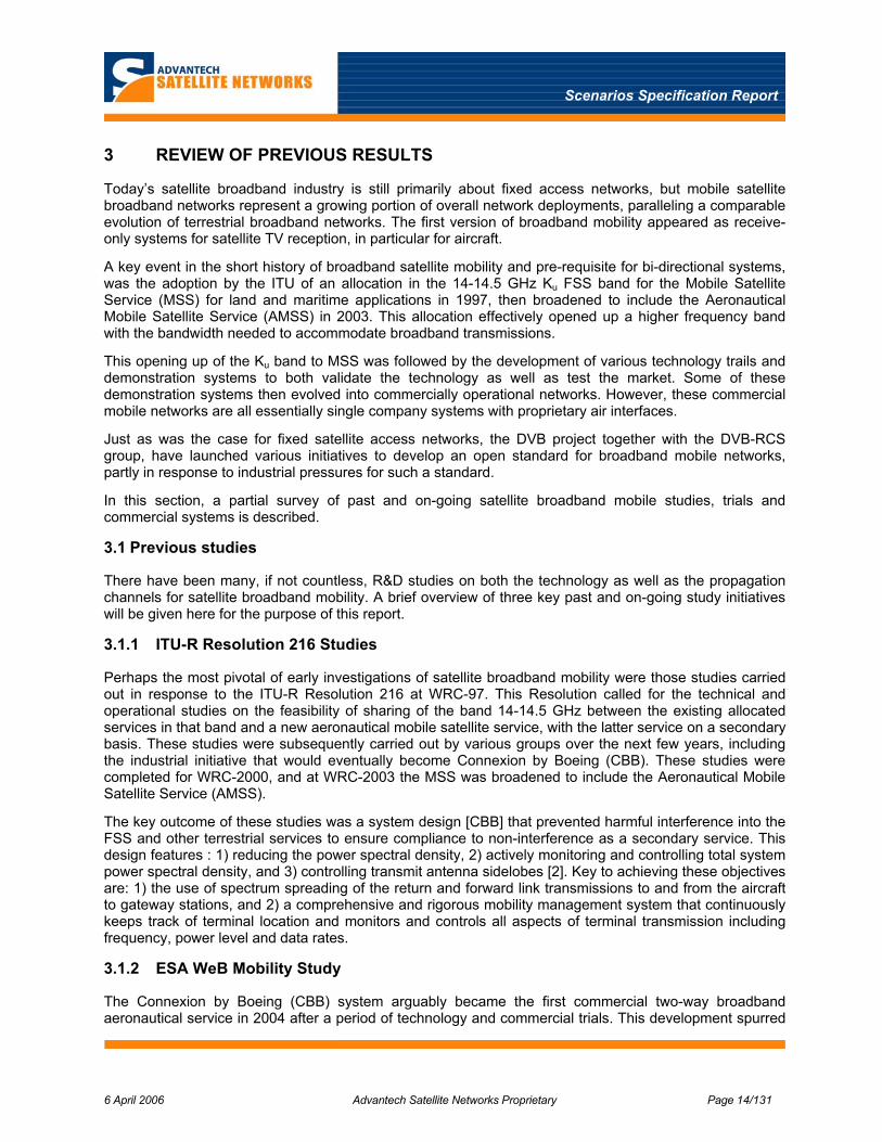
a satellite based infrastructure able to support multimedia [broadband] services including Internet and broadcast TV, to passengers of high speed trains. The trials were conducted in Italy (Bologna-Naples). The system architecture is illustrated in Figure 3-1.
The project highlighted the use of terrestrial gapfillers and fading mitigation techniques to ensure a seamless service in an electric railway scenario that involves three main types of obstruction: 1) periodic due to power line infrastructure (trellis, catenary), 2) non-periodic and momentary (buildings, trees, bridges), and 3) non-periodic and longer term (tunnels).
The transmission scheme was based on a 500 kbps SCPC return link and 16 Mbps DVB-S forward link, over a Ku band satellite. The key fade mitigation techniques demonstrated included: 1) space diversity reception, 2) channel interleaving and outer interleaver and error correcting code applied to forward link, and 3) data link layer signal processing.
The trial also served to develop the equipment required, including the multi-mode terminal, local area network and a low profile mechanically steered asymmetrical antenna mounted in the train roof.
FIGURE 3-1: FIFTH SYSTEM ARCHITECTURE
Scenarios Specification Report
6 April 2006 Advantech Satellite Networks Proprietary Page 17/131
3.2.2 21 NET
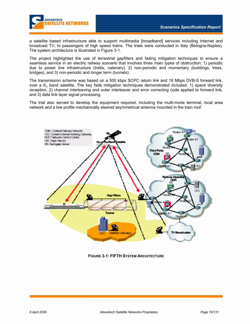
This is another high speed train project, supported by the European Space Agency ESA, with trails carried out initially in Spain (Madrid-Lerida, Madrid-Seville) followed by trials in France, Belgium, and the Netherlands (Brussels-Paris). The system architecture is illustrated in Figure 3-2.
The trials demonstrated 2 Mbps and 4 Mbps in the return and forward links over a Hispasat Ku band satellite at velocity up to 320 km/hr. This system uses WiFi gapfillers when in train stations, while apparently allowing for service outages going through tunnels or other obstructions. The 21 Net train uses only one large antenna, believed to use a Seatel stabil ised platform) enclosed in a radome was used. It is noted with some surprise that this approach did not use a low profile antenna.
The 21 NET system trials have been completed, and apparently the system is planning to offer a commercial service in the near future.
FIGURE 3-2: 21 NET SYSTEM ARCHITECTURE
3.3 Commercial Systems
There are now a surprising number of commercial satellite broadband mobile systems in operation considering the relatively short time the regulatory framework has been in place, although some of these
Scenarios Specification Report
6 April 2006 Advantech Satellite Networks Proprietary Page 18/131
are satellite receive only with a ground based return link and so did not require this framework. This observation may implicitly indicate that there is a market for these services and that they will be commercially viable. However, it is still not clear that commercial viability for satellite based broadband mobile service has yet been achieved, even in the case of CBB.
3.3.1 Aeronautical
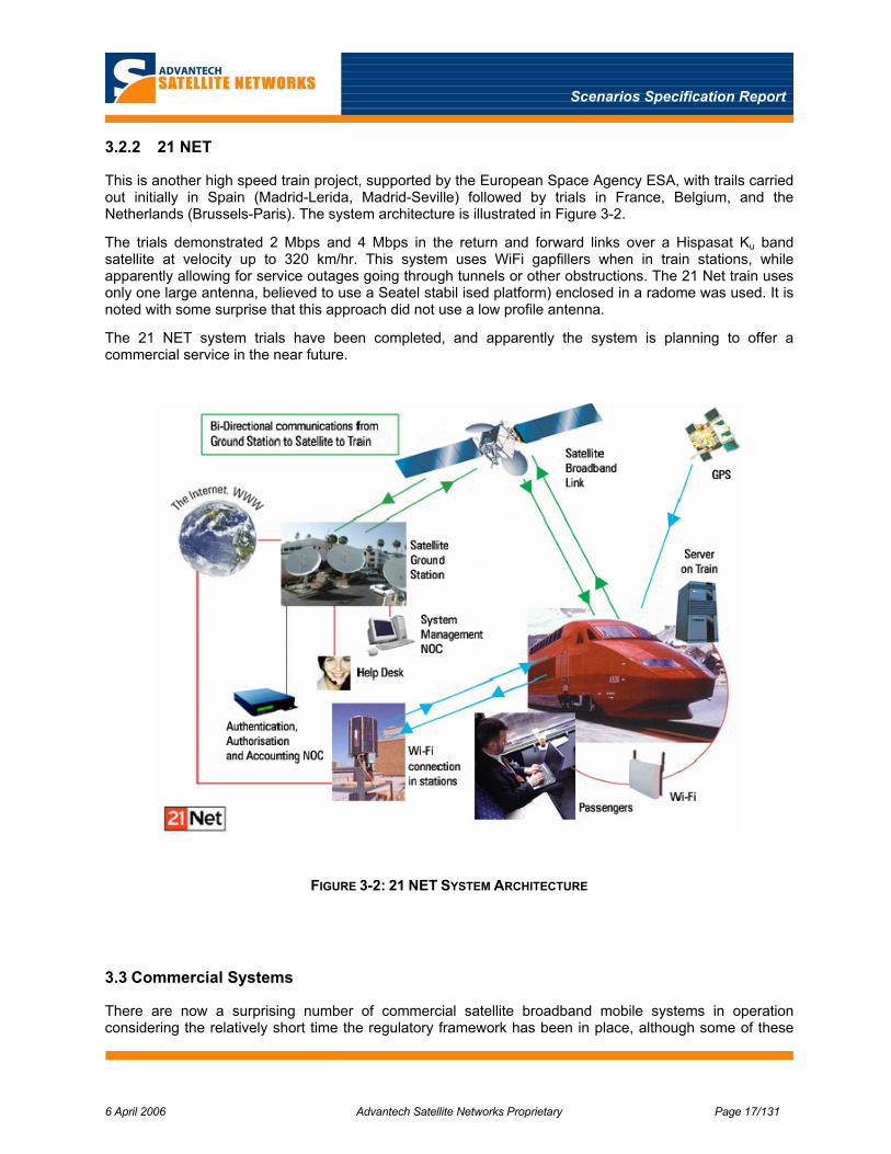
The leader and pioneer in commercial aeronautical satellite broadband service is undoubtedly Connexion by Boeing. Aside from CBB there are three other actual or advertised commercial services mentioned here: ARINC SKYLink, ROW44, and Inmarsat 4. An overview description of these services is given below along with a summary of the key parameters listed in Table 3-1 .
TABLE 3-1: SUMMARY OF KEY AERONAUTICAL MOBILE SERVICE PARAMETERS
Data Rate System Name
Forward Return
Description
Connexion by Boeing 5 Mbps 512 kbps – 1 Mbps
Passenger jet service for global coverage
ARINC SKYLink 512 kbps-3.2 Mbps
128 kbps Business jet service for regional (North American) coverage
ROW44 Up to 30 Mbps <= 64 kbps DBS forward capacity and L band or ground based return link (backchannel) in North America
Inmarsat 4 BGAN 432 kbps 432 kbps Multi-beam L band system
3.3.1.1 Connexion by Boeing
CBB supports aggregate data rates of 512 kbps on the return link and 5 Mbps on the forward link. In a recent conference paper presented by CBB [6] , a progress report is given of the rollout of the CBB service. The forward and return link architectures are illustrated in Figure 3-3 and Figure 3-4.
The CBB system supports 5 Mbps forward links and 512kbps -1 Mbps return links using a spread spectrum multiple access scheme. This transmission scheme is used to achieve interference mitigation required to operate on a secondary basis in the FSS band. Strict RL power control is used to comply with allowed aggregated EIRP spectral density. Slow closed loop and fast open loop power control are used. Required Eb/No is 4.5 dB on both FL and RL. Connexion by Boeing (CBB) system provides the following services to aircraft passengers:
Real-time two-way, high-speed Internet and e-mail Broadband corporate Intranet access, E-commerce, In-flight travel and destination information, Live video distribution (News, financial, sports and entertainment),

Scenarios Specification Report
6 April 2006 Advantech Satellite Networks Proprietary Page 19/131
FIGURE 3-3: CONNEXION FORWARD LINK ARCHITECTURE
FIGURE 3-4: CONNEXION RETURN LINK ARCHITECTURE

Scenarios Specification Report
6 April 2006 Advantech Satellite Networks Proprietary Page 20/131
3.3.1.2 ARINC SKYLink
Aside from Connection by Boeing there are two other broadband access aeronautical services. One is offered by ARINC and is called SKYLink, manufactured by ViaSat. This service is targeted primarily for private business jets since it supports lower aggregate data rates than CBB. SKYLink supports data rates of 128 kbps on the return link and between 512 kbps and 3.5 Mbps on the forward link.
The system is based on ViaSat Arclight technology which uses CRMA (Code Reuse Multiple Access), a spectrum spreading technique that permits use of small antennas and comply with the regulatory emission requirements. This system is similar to CBB but supports lower data rates.
The SKYLink air interface is further described in Appendix E.
3.3.1.3 ROW44
The other service, called ROW44, is an advertised service using HNS (Hughes Network Systems) Direcway access technology. It is planned that this service will use excess DBS bandwidth (!!!) for the forward path and either Inmarsat L band links or ground based Airphone type links for the return link (backchannel). It is unclear if ROW44 has actually gotten of the ground with its service. A key differentiator here from the other Ku band services is the use of BSS space segment instead of FSS for the forward path. This avoids any downlink interference problems with small antennas since BSS satellites are spaced 9 degrees apart. However the BSS will not support a return path which must then use another method such as an L band Inmarsat link. Also there is some question (in this writers mind) about the economics of using precious DBS bandwidth for web browsing etc., although apparently there is sometimes excess bandwidth on DBS carriers that could be used to piggyback internet traffic.
3.3.1.4 BGAN
Although not categorically part of the Ku band broadband systems, the new Inmarsat 4 system supports near-broadband data rates of 432 kbps in the forward and return links with its BGAN service. This is achieved in the limited L band bandwidth, by the use of very bandwidth efficient transmission schemes in conjunction with the small high gain spot beams. While the return rates are high enough, the forward rate is still somewhat limited in speed and would probably require multiple carriers for a large aircraft. It should also be noted that fully mobile operation of BGAN is still a few years away; the initial deployment if for nomadic terminals only.
3.3.2 Maritime
Satellite based broadband mobile service is already being provided to cruise ships and possibly also to ferries using proprietary VSAT terminals that are equipped with a stabilised platform such as that manufactured by Seatel. The Seatel 96 series antennas for Ku band are 1 and 1.2 m diameter.
It is however noted that Nera now offers a DVB-RCS access terminal, called Nera SatLink Marine, for a maritime application (superyacht). This terminal uses a 1 m antenna on a stabilised (servo-controlled) mount in a radome. The system is advertised to support an 8 Mbps IP throughput on the forward path and apparently a 2 Mbps return path.
Advantech Satellite Networks offers a similar DVB-RCS terminal, based on the SeaTel platform.
These installations all employ antennas that are of the “VSAT type” in terms of size and therefore comply to FSS regulatory requirements.

Scenarios Specification Report
6 April 2006 Advantech Satellite Networks Proprietary Page 21/131
3.3.3 Land
In the realm of satellite broadband for land mobile, three distinct classes of commercial services are noted here. The first and foremost is service to high speed trains, followed by service to trucks and RVs (caravans) as described below along with a summary of data rates and key parameters given in Table 3-2 below.
Service to high speed trains includes the Icomera system and 21NET, although the latter is only in the initial stages of commercialisation. The Icomera system uses a combination of terrestrial and satellite transmission links to provide its service; the satellite is used for the forward path receive only when it is available on the trains route. For the return path a combination of GSM and WLAN links are used, again depending on availability along the trains route. Although not advertised, a minimum return data rate of 384 kb/s can be supported.
21 NET is an Anglo-Belgian company offering bi-directional satellite based broadband service. As noted above this system has undergone a number ESA sponsored trials in Spain as well as France, Belgium and the Netherlands.
The narrowband EutelTracs and OmniTracs systems are noted here simply because these are perhaps among the first true mobile services in the Ku band. A broadband service could eventually support such low-rate applications as part of an overall broadband multimedia service.
Finally, the increasing use of mobile DBS receivers on personal RVs and Caravans is also noted here since this potentially points to a market for broadband access as well. Transportable satellite broadband access on jeeps and SUVs already exists as well, for applications such as emergency restoration of communications and remote news gathering, although these are not licensed for mobile operation.
TABLE 3-2: SUMMARY OF KEY LAND MOBILE SERVICE PARAMETERS
Data Rate System Name
Forward Return
Description
Icomera Mobile System (IMS)
30 Mbps ? >384 kbps Satellite for forward and WLAN / GSM for return link. Currently in UK and Scandinavia
21 NET 4 Mbps 2 Mbps Pre-commercial stage in Europe
EutelTracs /OmniTracs
96 kbps 55 bps Very low data rate for truck fleet management using Ku band FSS satellites
RVs, Jeeps, SUVs 30 Mbps 256 kbps -2 Mbps
Satellite DBS receive only and transportable broadband access
3.4 Commercial Equipment
As noted earlier, the commercialised mobile satellite broadband systems are for the most part proprietary systems. Nevertheless, some key subsystems of the equipment used by these systems are either entirely or partly agnostic to the specific air interface used. This is particularly true of the mobile ODU /antenna subsystem. This is crucial to the implementation of any mobile system, in order to achieve the required stabilisation, antenna tracking and steering while maintaining antenna sidelobe performance, especially for low profile asymmetrical antennas.

Scenarios Specification Report
6 April 2006 Advantech Satellite Networks Proprietary Page 22/131
3.4.1 ODUs /Antenna systems
The mobile terminals of the existing proprietary mobile systems use outdoor units that are in some cases commercially available and advertised as standalone products or have been supplied exclusively as part of that particular system. Although at this stage it is possible to identify the type of antenna system required for a particular mobile application, it is too early to identify exactly which of these are potential suppliers are suitable candidates for a commercial ODU. However, the survey given below in Table 3-3 of such systems represents a useful catalogue of existing ODUs for broadband mobile systems.
In general, there are two broad categories of commercial mobile antenna systems technologies: 1) satellite receive-only and 2) bi-directional satellite transmit/receive operation.
Mobile antennas for receive-only systems have appeared first to support DVB-S satellite TV reception to aircraft, high speed trains, and even personal vehicles such as RVs (caravans). For the aeronautical application, “receive-only” systems for satellite TV reception include the LiveTV service in North America. Since this operates with DBS satellites that have a 9 degree orbit spacing, the downlink interference is also avoided, since there is sufficient antenna isolation for this separation. Examples of these receive only systems include the EMS Condor and DBA-1160 MR, all the Raysat array antennas and the ORBIT train antenna system. If required, such systems typically operate in conjunction with either a terrestrial return path (Raysat) or an Inmarsat L band satellite return path (EMS).
Examples of commercial bi-directional broadband mobile systems include the Seatel1, Boeing /Melco (Connexion), and recently Raysat mobile antenna systems. The Boeing antenna is the commercial Ku band reflector antenna for the Connexion aeronautical Ku band system. The Seatel mobile antenna system is a commercial Ku or Ka band stabilised reflector for maritime VSAT type applications, and the Raysat Eagleray antennas are for Ku band land mobile applications.
Along with antennas used by Connexion and SkyLink, the Seatel antenna system is a commercial bidirectional mobile Ku / Ka band system. The VSAT sized Seatel antennas uses advanced conical scanning to ensure pointing accuracy of 0.2°. A less aggressive technique for smaller antennas is based on a step tracking sometimes referred to as Hill Climbing, which is used in the EMS DBA –1160 MR TV receive only antenna. This achieves a tracking accuracy of ± 1.5°, suitable for an antenna beamwidth of about 7°.
There are a number of proven techniques and technology available to achieve acquisition and tracking of a satellite from a moving platform at Ku and higher frequencies, as summarised in Table 3-3 below.
TABLE 3-3: SURVEY OF MOBILE ANTENNA SYSTEM TECHNOLOGY.
Manufacturer Mobile Antenna System
SeaTel • Stabilised reflector antenna systems for satellite Ku / Ka TX/RX (commercial marine)
• Aperture: >= 1 m diameter
• Platform stabilisation; 3-axis at 90 deg/sec slew rate
• Tracking: conical scanning with 0.2° peak point error for ± 25 deg roll and ± 15 deg pitch
1 Seatel Inc., www.seatel.com

Scenarios Specification Report
6 April 2006 Advantech Satellite Networks Proprietary Page 23/131
Manufacturer Mobile Antenna System
Boeing /Melco • Connexion elliptical reflector for satellite Ku TX/RX (commercial aeronautical – CBB)
• Aperture: ~30cm X 80 cm
• Condor wavequide slot array antenna for satellite Ku / Ka RX only (aeronautical LiveTV)
• Aperture: 83 cm x 13 cm
• Tracking: autonomous GPS /inertial and conical scan, mechanical elevation and azimuth; 360 deg Az, 16.5-67.5 deg Elev, 5 deg/sec slew rate
• ACTS wavequide slot array antenna for satellite Ka TX/RX (demonstration)
• DarkStar phased array antenna for satellite Ku RX only (military application)
• Tracking: electronic elevation and mechanical azimuth
• DBA-1160MR reflector antenna for satellite Ku RX only (aeronautical LiveTV)
• Aperture: 29 cm diameter
• Tracking: mechanical elev/azimuth 40 deg/sec slew rate
EMS Technologies
• CPA contiguous paraboloid array (reflector) antenna for satellite Ku / Ka /Q TX/RX (prototype)
• Antenna aperture: 74 cm x 26.7 cm
• Tracking: mechanical elev/azimuth using modified Condor system
Raysat • Planer phased array antenna for satellite Ku RX only (Live TV) for trains, RVs, cars
• Trains: TorpedoRay – Aperture: 110 cm x 27.5 cm, Tracking: 15-75 deg Elev and 360 deg Az; slewing rate of 30 deg/sec
• RVs: SpeedRay –Aperture: 115 cm x 89 cm x 14.5 cm, Tracking: 20-70 deg Elev, 360 deg Az, slewing rate of 30 deg/sec
• Cars: StealthRay – Aperture: 89 cm x 78 cm x 5 cm, Tracking: 30-90 deg Elev, 360 deg Az, slew rate of 60 deg /s Elev, 30 deg/s Az
Orbit • AL-2600 11/12 GHz receive mobile asymmetrical dual antenna system with elevation over azimuth steering and RF step tracking; dual antenna for high speed train application for diversity reception

Scenarios Specification Report
6 April 2006 Advantech Satellite Networks Proprietary Page 24/131
4 APPLICATIONS AND MARKETS
This section addresses the possible markets for a broadband mobile satellite system based, where possible, on openly available traffic forecasts and, where lacking, on a subjective assessment by the writer. In addition to the overall market size, this assessment of the potential market also takes into account the presence of the satellite competitors, namely the terrestrial infrastructure (3G/4G and DVB-H networks), aiming at the market under consideration.
The markets under consideration here are those related to public transportation (cruise ships and ferries for maritime, buses and trains for terrestrial, passenger and executive aircrafts for the aeronautical domain) and, to a lesser extent, private transportation. For this last market, the major prospects for a satellite system usage probably resides in the segment of motor homes (campers) and caravans where broadband internet connection may be desired to exploit internet services even during holiday periods.
The broadband internet services which are considered most relevant for the above market segments include:
• High speed internet web browsing
• Virtual Private Networking
• Instant messaging
• File transfer (not only FTP but mainly peer-to-peer applications)
• Audio and video streaming
• Audio and video conferences
• Video and radio on demand
• Voice services (VoIP)
The expected aggregate rates have been defined for the different applications, on the basis of individual service requirements, number of passengers/users requiring terminal access, and travel duration. This led to ranges from several tens of kbit/s to a few Mbit/s on the forward link and from typically 25 kbit/s to 500 kbit/s on the return link. The target availability and quality of service are equivalent to those of broadband DVB-RCS access.
Clearly a difficulty in this kind of estimate is the fact that service demand also depends on the service cost. This may not be taken into account in our brief survey and this will add to the difficulty in making reliable estimates of service / application requirements in the aeronautical, maritime, train, and vehicular markets.
Broadband (ADSL, cable) Internet subscriptions have skyrocketed in the last few years (from an estimated 3 million subscribers in 1999 to 63 million in 2002 according to an ITU report).
The current number of broadband Internet subscription is almost certainly exceeding a couple hundred million of subscribers. Wireless Internet access has also more recently started pervading the market as most laptops and handheld computers manufactured today are already equipped with WiFi transceivers.
Thanks to this explosion of broadband Internet access, home users are now familiar with broadband applications like: videoconferencing, web casting, photo sharing, peer-to-peer file exchange, and so on. Also, less bandwidth hungry applications like VoIP are now becoming pervasive.

Scenarios Specification Report
6 April 2006 Advantech Satellite Networks Proprietary Page 25/131
Similarly, also in the business world the need for broadband applications has become even more pervasive than in the home market segment, although emphasis may be on, e.g. email (often with large attachments) rather than peer-to-peer file exchange.
The same services offerings as available from current terrestrial broadband Internet connections are the targets for our mobile markets. Furthermore, this offering should provide the same or similar QoS as terrestrial connections, in order to be attractive from a commercial point of view and, most importantly, it should be provided at reasonable cost.
These are difficult targets especially for some mobile scenarios where the need of interference mitigation and / or handover will impact the service cost and QoS.
In the following a somewhat more in depth look at the different market domains will be given.
4.1 Aeronautical
In terms of possible traffic volume, the aeronautical market appears to be the most promising one (together with the maritime one) for a satellite, DVB-S / DVB-RCS based, communication system.
In-flight, terrestrial-based offerings to planes are, in fact, limited to telephony and low-rate data services. For long-haul flights, such services are also offered via satellite, usually INMARSAT, which is historically the major player in this sector.
In the order of 7,000 aircraft are using INMARSAT services today, of which 4,500 are using the airline-based Aero-H, H+ and I services. INMARSAT is trying to offer airlines an evolutionary approach to broadband services. This is exemplified by the Swift64 service offering that was introduced in 2002. Swift64 offers a data rate of 64kbit/s, a vast improvement on the 9.6 kbit/s which was available with the previous Aero-H. Higher throughput may be also achieved by using multiple channels (up to 4) simultaneously. By doing so, data rates of 256 kbit/s can be achieved.
Swift64 supports both ISDN and IP services, including e-mail, large file transfer, and videoconferencing.
According to the INMARSAT vision, Swift64 is the first step on the evolutionary eventually path leading to broadband services. In particular, with the availability of the INMARSAT-4 spacecrafts even higher data rates are possible (432 kbit/s), using the Broadband Global Area Network (BGAN) system. BGAN is already in commercial service; however it is currently only for nomadic terminals and thus not yet able to support full mobility.
However, the INMARSAT offering, being at L-band, would in the end suffer from the limited available bandwidth. Furthermore, 432 kbit/s may not be enough for the Forward Link direction where higher throughput may be desired for some of the applications.
New broadband aeronautical communications are thus currently emerging with potentially higher throughput than the INMARSAT offer. Ku-band systems are now being offered by ARINC, through its Skylink system and Boeing with its Connexion by Boeing system.
These new systems were conceived for operation at Ku-band and are thus direct competitor to a DVB-S / DVB-RCS based solution. However, they are proprietary systems and standardisation of an access solution in the frame of DVB is considered a must here. A brief overview of both systems is given in Appendix E.
We are not aware of any current or planned terrestrial-based broadband systems designed specifically for aeronautical use
Most land mobile networks would have, in fact, difficulty coping with the aeronautical environment due to mainly the high altitude of aircraft which would render a terrestrial cellular approach very problematic due to the large-area visibility of the terminals which would prevent a large frequency reuse of the spectrum

Scenarios Specification Report
6 April 2006 Advantech Satellite Networks Proprietary Page 26/131
resources. Finally, the high speed of aeronautical terminals and the consequent frequent handovers, would further complicate the reuse of terrestrial technology and / or infrastructures.
Since the above problems are of a fundamental nature and not due to limitations in the technology, the prospects of the terrestrial competition in the aeronautical domains is considered to be small even in the foreseeable future. Furthermore trans-oceanic coverage can only provided by satellite. Aeronautical services are therefore a key target area for satellite-based delivery of broadband multimedia.
Figure 4-1 shows the worldwide population of commercial aircraft. The priority segment is generally considered to be the one of wide body aircraft used for long range communications (transatlantic). However regional range (e.g. European) aircraft are also an interesting market for this kind of market.
FIGURE 4-1 AERONAUTICAL SEGMENT (FROM MOWGLY [40])
The number of potential terminals is corresponding to the number of aircraft shown in the above figure. Table 4-1 presents an overview of applications that appears most attractive for aeronautical terminals. Also included is an estimation of the required data rates for each of those applications in the forward and return links.
It should be noted that a significant portion of the FL traffic will likely come from the TV broadcasting service.
The average traffic per user for the web browsing service has been assumed equal to 15 kbit/s in the Forward Link2 direction and 5 kbit/s in the Reverse Link direction in compliance with the parameters considered in Section 7 on traffic model,
For the VoIP service we assume an average rate per connection of 8 Kbit/s. This takes into account the potential advantage coming from voice activation (voice activity is typically 40% on the average). It should
2 For the FL direction the Web Server Model in Section 7 assumes that each page is composed of a main object of 10.7 KB average size and embedded objects of average sizes of 7.7 KB. As there are on the average 5.64 embedded objects per page and the average reading time per page is 30 s., this translates to about 15 kbit/s average rate.
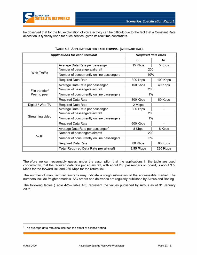
Scenarios Specification Report
6 April 2006 Advantech Satellite Networks Proprietary Page 27/131
be observed that for the RL exploitation of voice activity can be difficult due to the fact that a Constant Rate allocation is typically used for such service, given its real time constraints.
TABLE 4-1: APPLICATIONS FOR EACH TERMINAL (AERONAUTICAL).
Required data rates Applications for each terminal FL RL
Average Data Rate per passenger 15 Kbps 5 Kbps Number of passengers/aircraft 200 Number of concurrently on line passengers 10% Web Traffic
Required Data Rate 300 kbps 100 Kbps Average Data Rate per passenger 150 Kbps 40 Kbps Number of passengers/aircraft 200 Number of concurrently on line passengers 1%
File transfer/ Peer to peer
Required Data Rate 300 Kbps 80 Kbps Digital / Web TV Required Data Rate 2 Mbps -
Average Data Rate per passenger 300 kbps - Number of passengers/aircraft 200 Number of concurrently on line passengers 1% Streaming video
Required Data Rate 600 Kbps - Average Data Rate per passenger3 8 Kbps 8 Kbps Number of passengers/aircraft 200 Number of concurrently on line passengers 5% VoIP
Required Data Rate 80 Kbps 80 Kbps Total Required Data Rate per aircraft 3,55 Mbps 260 Kbps
Therefore we can reasonably guess, under the assumption that the applications in the table are used concurrently, that the required data rate per an aircraft, with about 200 passengers on board, is about 3.5, Mbps for the forward link and 260 Kbps for the return link.
The number of manufactured aircrafts may indicate a rough estimation of the addressable market. The numbers include freighter models. A/C orders and deliveries are regularly published by Airbus and Boeing.
The following tables (Table 4-2—Table 4-3) represent the values published by Airbus as of 31 January 2006.
3 The average data rate also includes the effect of silence period.

Scenarios Specification Report
6 April 2006 Advantech Satellite Networks Proprietary Page 28/131
TABLE 4-2: ORDERS AND DELIVERIES PUBLISHED BY AIRBUS FOR EUROPE
Summary to 31st of January 2006 for Europe
A318/A319/A320/A321 A300/A310 A330/A340/A350 A380 TOTAL
Total Orders 1248 216 277 31 1772
Total Deliveries 803 216 221 1240
Aircraft in Operation 1021 148 256 1425
TABLE 4-3: ORDERS AND DELIVERIES PUBLISHED BY AIRBUS FOR NORTH AMERICA
Summary to 31st of January 2006 for North America
A318/A319/A320/A321 A300/A310 A330/A340/A350 A380 TOTAL
Total Orders 1714 239 273 30 2256
Total Deliveries 1211 228 167 1606
Aircraft in Operation 791 235 52 1078
We have reviewed the Boeing orders and delivery by of 31 January 2006: the commercial aircraft delivered are 15353 and about 12000 are working now, representing about 75% of world fleet.
By this information, we can evaluate approximately that there are 8000 aircrafts in operation in this scenario with about 200 passengers for each (considering a higher number of aircraft with a smaller number of passengers balanced by a certain number of aircraft with a larger number of 200 passengers, as show also by Figure 4-1).
Supposing that only 10% of these aircrafts is in the footprint of a satellite, we can estimate that the total required data rate is 2.84 Gb/s for the forward link and 208 Mbps for the return link, as shown in Table 4-4.

Scenarios Specification Report
6 April 2006 Advantech Satellite Networks Proprietary Page 29/131
TABLE 4-4: TOTAL REQUIRED THROUGHPUT FOR AERONAUTICAL MARKET
Required data rates FL RL
Required Data Rate for each aircraft 3.55 Mbps 260 Kbps Aircrafts in operation 8000 Total number of passengers 1,6 millions Number of concurrently aircrafts 10% Total Required Data Rate 2840 Mbps 208 Mbps
4.2 Maritime
Vessels on the high seas will not usually be able to access land-based services, and will be a “captive audience” for satellite-based delivery in much the same way as aeronautical users. However, large sections of the shipping industry operate in coastal waters, including most of the passenger traffic (yachts, ferries and cruise ships) that is of prime interest as potential customers. In these regions, there may be at least some coverage by land mobile networks. At present, this is largely limited to cellular telephony networks, providing for example the GSM-based pay phones commonly available on ferries. Higher-speed networks such as 3G (UMTS) are generally based on smaller cells than GSM and can thus only reach a few kilometres offshore, and only near major port cities.
At present, there is therefore little terrestrial competition to satellite-based broadband services to ships. One can of course envisage hybrid arrangements in which the forward link is satellite based and the return link uses lower-speed cellular networks. It is also entirely possible that coastal-water coverage of 3G or other networks can be improved, should the operators recognise a potential market.
In summary, the prospects for satellite communication in this domain can be considered almost as good as for the aeronautical domain although a potential competition from terrestrial networks may arise in the coastal navigation segment of the maritime domain.
Figure 4-2 shows the worldwide population of vessels. The priority segment is generally considered to be the one of cruise ships used for multi-day trips for tourism and ferries used for regular passenger services. However also large yachts are an interesting market for the broadband service.
The number of potential terminals is corresponding to the number of vessels shown in the above figure. Table 4-5 presents an overview of some applications that are potentially applicable to this domain and an evaluation of potentially required data rates for each of the most interesting applications in the forward and return link.

Scenarios Specification Report
6 April 2006 Advantech Satellite Networks Proprietary Page 30/131
FIGURE 4-2: MARITIME SEGMENT (FROM MOWGLY [40])
TABLE 4-5: APPLICATIONS FOR EACH TERMINAL (CRUISE SHIP)
Required data rates Applications for each terminal FL RL
Average Data Rate per passenger 15 Kbps 5 Kbps Number of passengers/vessel 1000 Number of concurrently on line passengers 5% Web Traffic
Required Data Rate 750 kbps 250 kbps Average Data Rate per passenger 150 Kbps 40 Kbps Number of passengers/vessel 1000 Number of concurrently on line passengers 0.5%
File transfer/ Peer to peer
Required Data Rate 750 kbps 200 kbps Digital /Web TV Required Data Rate 2 Mbps -
Average Data Rate per passenger 300 Kbps - Number of passengers/vessel 1000 Number of concurrently on line passengers 1% Streaming video
Required Data Rate 3 Mbps - Average Data Rate per passenger 8 Kbps 8 Kbps Number of passengers/vessel 1000 Number of concurrently on line passengers 5% VoIP
Required Data Rate 400 Kbps 400 Kbps Total Required Data Rate per vessel 6.9 Mbps 850 kbps

Scenarios Specification Report
6 April 2006 Advantech Satellite Networks Proprietary Page 31/131
Therefore we could estimate, under the assumption that the applications in the table are used concurrently in the vessels, that the required data rate per a vessel, with about 1000 passenger on board, is about 6.9 Mbps for the forward link and 850 kbps for the return link.
By the information of potential terminals in Figure 4-2, it appears that there are approximately 300 vessels (mainly cruise and ferries) in operation in Europe with about 1000 passengers for each (considering a higher number of vessels with a smaller number of passenger balanced by a certain number of vessels with a larger number of 1000 passengers, as shown also by Figure 4-2). Assuming that only 25% of these vessels are simultaneously operational, a potential traffic requirement for a European system of about 517 Mbit/s for the forward link and 63.75 Mbit/s for the return link would be required, as shown in Table 4-6.
TABLE 4-6: TOTAL REQUIRED THROUGHPUT FOR MARITIME MARKET
Required data rates FL RL
Required Data Rate for each vessel 6.9 Mbit/s 850 kbit/s Vessels in operation 300 Total number of passengers 300.000 Number of concurrently vessels 25% Total Required Data Rate 517 Mbit/s 63.75 Mbit/s
4.3 Land Mobile
The positioning of a possible mobile DVB-S / DVB-RCS in terrestrial market appears much more critical with respect to the prospects in the aeronautical and maritime domains, due to strong competition coming from the terrestrial systems (particularly 3G/4G cellular systems). Hence, although the land mobile communication potential traffic volume are the largest, the target served volume for a satellite system will not necessarily be larger than in the aeronautical and maritime domains, at least in the shorter time period. Terrestrial competition is considered further in Section 10.
Taking into account also the requirement for more significant adaptation of the current DVB-S and DVB-RCS standards to suit the land mobile environment, it appears that this market is the most difficult for satellites.
As a consequence of the above facts, the market assessment for the satellite land mobile domain is less consolidated.
Within the land mobile domain we can concentrate on train communication systems, as it appears the most interesting, and the bus and caravan / camper markets. The private car market appears the less attractive at least in the near / medium term and will not be addressed here.
4.3.1 Trains
Figure 4-3 shows the worldwide population of trains. The priority segment is generally considered to be the one of fast trains used for quick regular passenger service. However, also traditional trains, for the long-distance, can be an interesting market.
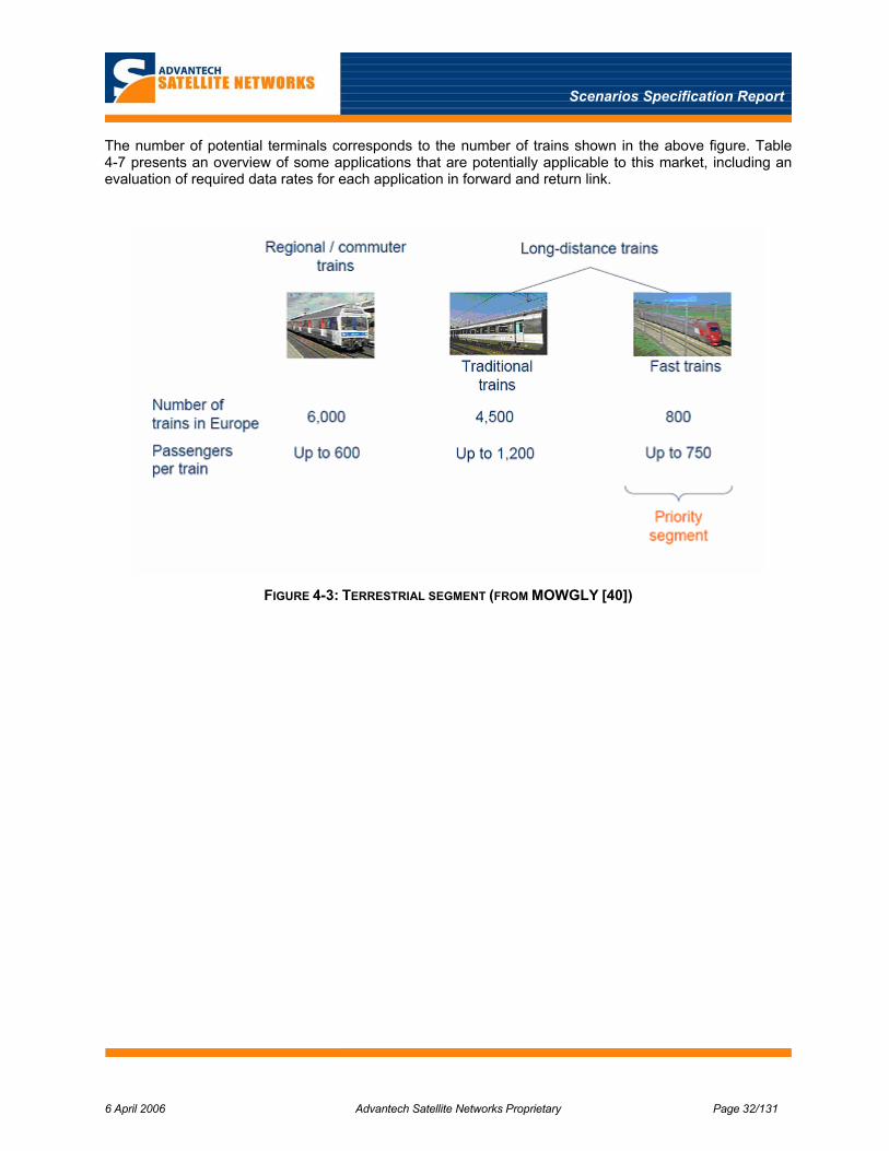
Scenarios Specification Report
6 April 2006 Advantech Satellite Networks Proprietary Page 32/131
The number of potential terminals corresponds to the number of trains shown in the above figure. Table 4-7 presents an overview of some applications that are potentially applicable to this market, including an evaluation of required data rates for each application in forward and return link.
FIGURE 4-3: TERRESTRIAL SEGMENT (FROM MOWGLY [40])
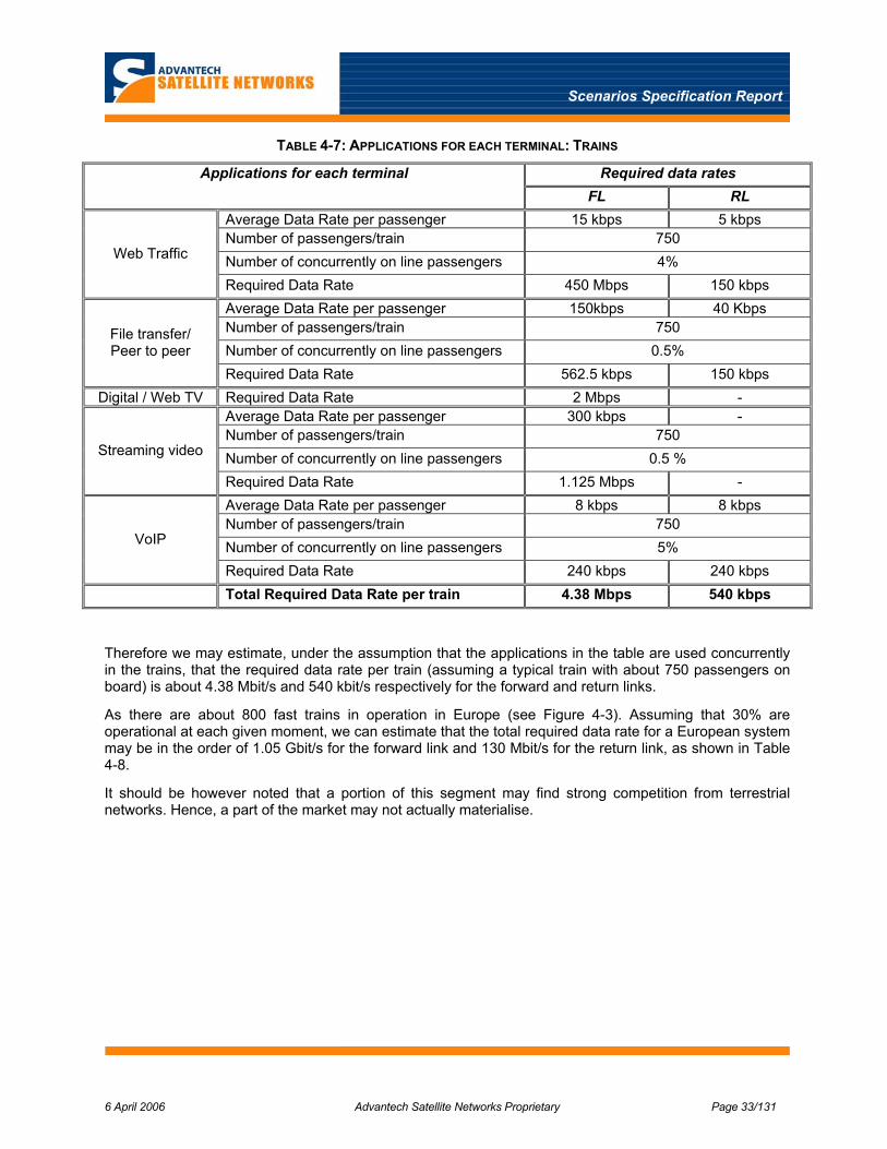
Scenarios Specification Report
6 April 2006 Advantech Satellite Networks Proprietary Page 33/131
TABLE 4-7: APPLICATIONS FOR EACH TERMINAL: TRAINS
Required data rates Applications for each terminal FL RL
Average Data Rate per passenger 15 kbps 5 kbps Number of passengers/train 750 Number of concurrently on line passengers 4% Web Traffic
Required Data Rate 450 Mbps 150 kbps Average Data Rate per passenger 150kbps 40 Kbps Number of passengers/train 750 Number of concurrently on line passengers 0.5%
File transfer/ Peer to peer
Required Data Rate 562.5 kbps 150 kbps Digital / Web TV Required Data Rate 2 Mbps -
Average Data Rate per passenger 300 kbps - Number of passengers/train 750 Number of concurrently on line passengers 0.5 % Streaming video
Required Data Rate 1.125 Mbps - Average Data Rate per passenger 8 kbps 8 kbps Number of passengers/train 750 Number of concurrently on line passengers 5% VoIP
Required Data Rate 240 kbps 240 kbps Total Required Data Rate per train 4.38 Mbps 540 kbps
Therefore we may estimate, under the assumption that the applications in the table are used concurrently in the trains, that the required data rate per train (assuming a typical train with about 750 passengers on board) is about 4.38 Mbit/s and 540 kbit/s respectively for the forward and return links.
As there are about 800 fast trains in operation in Europe (see Figure 4-3). Assuming that 30% are operational at each given moment, we can estimate that the total required data rate for a European system may be in the order of 1.05 Gbit/s for the forward link and 130 Mbit/s for the return link, as shown in Table 4-8.
It should be however noted that a portion of this segment may find strong competition from terrestrial networks. Hence, a part of the market may not actually materialise.

Scenarios Specification Report
6 April 2006 Advantech Satellite Networks Proprietary Page 34/131
TABLE 4-8: TOTAL REQUIRED THROUGHPUT FOR TRAIN MARKET
Required data rates FL RL
Required Data Rate for each train 4.38 Mbit/s 540 kbit/s Trains in operation 800 Total number of passengers 600.000 Number of concurrently train 30% Total Required Data Rate 1.05 Gbit/s 130 Mbit/s
4.3.2 Buses
Given the above developments, potential data rates in the range of a few Mbps for the forward link and hundreds of kbit/s for the reverse link, should be considered as minimum target for the passenger aircraft, trains or ships. Somewhat reduced rate requirements can be accepted for buses or caravans / campers.
Table 4-9 presents an overview of some applications that are potentially applicable to this market segment and an evaluation of the required data rates per terminal. The forward link the requirements are strongly dominated by the TV service.
For estimating the potential number of terminals only buses used for long trip should be considered. This number has not yet been assessed.
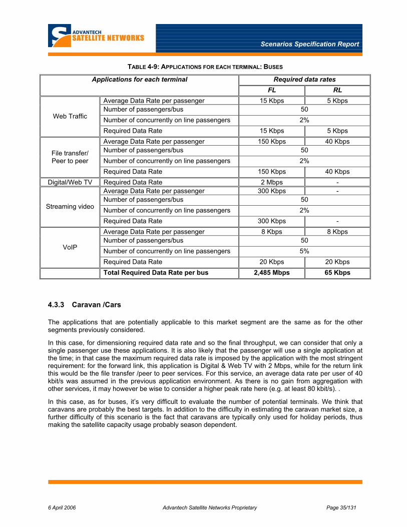
Scenarios Specification Report
6 April 2006 Advantech Satellite Networks Proprietary Page 35/131
TABLE 4-9: APPLICATIONS FOR EACH TERMINAL: BUSES
Required data rates Applications for each terminal FL RL
Average Data Rate per passenger 15 Kbps 5 Kbps Number of passengers/bus 50 Number of concurrently on line passengers 2% Web Traffic
Required Data Rate 15 Kbps 5 Kbps Average Data Rate per passenger 150 Kbps 40 Kbps Number of passengers/bus 50 Number of concurrently on line passengers 2%
File transfer/ Peer to peer
Required Data Rate 150 Kbps 40 Kbps Digital/Web TV Required Data Rate 2 Mbps -
Average Data Rate per passenger 300 Kbps - Number of passengers/bus 50 Number of concurrently on line passengers 2% Streaming video
Required Data Rate 300 Kbps - Average Data Rate per passenger 8 Kbps 8 Kbps Number of passengers/bus 50 Number of concurrently on line passengers 5% VoIP
Required Data Rate 20 Kbps 20 Kbps Total Required Data Rate per bus 2,485 Mbps 65 Kbps
4.3.3 Caravan /Cars
The applications that are potentially applicable to this market segment are the same as for the other segments previously considered.
In this case, for dimensioning required data rate and so the final throughput, we can consider that only a single passenger use these applications. It is also likely that the passenger will use a single application at the time; in that case the maximum required data rate is imposed by the application with the most stringent requirement: for the forward link, this application is Digital & Web TV with 2 Mbps, while for the return link this would be the file transfer /peer to peer services. For this service, an average data rate per user of 40 kbit/s was assumed in the previous application environment. As there is no gain from aggregation with other services, it may however be wise to consider a higher peak rate here (e.g. at least 80 kbit/s). .
In this case, as for buses, it’s very difficult to evaluate the number of potential terminals. We think that caravans are probably the best targets. In addition to the difficulty in estimating the caravan market size, a further difficulty of this scenario is the fact that caravans are typically only used for holiday periods, thus making the satellite capacity usage probably season dependent.

Scenarios Specification Report
6 April 2006 Advantech Satellite Networks Proprietary Page 36/131
5 REGULATORY ENVIRONMENT
In this section, the regulatory environment will be described for radio transmissions of a mobile satellite broadband system, and for regulations related to the environmental profile for operation of the terminal equipment for the particular mobile application.
For a hybrid satellite broadband network employing terrestrial gapfillers to extend coverage, the gapfiller network itself requires a Mobile and Fixed Services allocation depending on the type of network used. The regulatory environment for the terrestrial gapfiller is reviewed in a separate subsection below.
5.1 Radio Transmission Regulations
The regulatory environment for the broadband mobile satellite service (MSS) consists of: 1) the frequency allocations that have been established for MSS by the International Telecommunications Union (ITU), and 2) the standards and recommendations by various standards bodies.
This general regulatory framework for the MSS is described below, covering aspects common to all mobile applications. This is followed by a description of the specific interference scenarios and any additional aspects that are specific to the mobile application.
5.1.1 Frequency Allocations
For the ITU-R Mobile Satellite Service (MSS) a number of frequency allocations are assigned in the Ku and Ka bands for broadband mobile communications as summarised in Table 5-1 below. The detailed frequency allocation tables for the Ku and Ka bands are given below in Table 5-2 and Table 5-3.
TABLE 5-1: ITU-R MOBILE SATELLITE SERVICE (MSS) ALLOCATIONS
BAND Region 1 Region 2 Region 3
Ku 14-14.5 GHz (Earth-to-space) secondary
19.7-20.1 GHz (space-to-Earth)
Secondary
19.7-20.1 GHz
PRIMARY
19.7-20.1 GHz
secondary
20.1-21.2 GHz (space-to-Earth) PRIMARY
29.5- 29.9 GHz (Earth-to-space)
Secondary
29.5- 29.9 GHz
PRIMARY
29.5- 29.9 GHz
secondary
Ka
29.9-30 GHz (Earth-to-space) PRIMARY
For the Ku band allocation, the table above indicates that the MSS is secondary to all other services, in particular the Fixed Satellite Service (FSS) as detailed in Table 5-2 below. This regulatory requirement imposes a significant constraint on the design and operation of broadband Ku band MSS systems as considered later in this section.
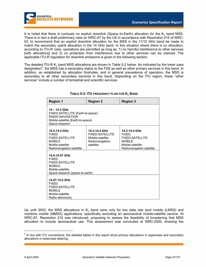
Scenarios Specification Report
6 April 2006 Advantech Satellite Networks Proprietary Page 37/131
It is noted that there is curiously no explicit downlink (Space–to-Earth) allocation for the Ku band MSS. There is in fact a draft preliminary view on WRC-07 by the US in accordance with Resolution 415 of WRC-03, to recommend that an explicit downlink allocation for the MSS in the 11/12 GHz band be made to match the secondary uplink allocation in the 14 GHz band. In this situation where there is no allocation, according to ITU-R rules, operations are permitted as long as: 1) no harmful interference to other services [with allocations] and 2) no protection from interference due to other services can be claimed. The applicable ITU-R regulation for downlink emissions is given in the following section.
The detailed ITU-R Ku band MSS allocations are shown in Table 5-2 below. As indicated by the lower case designation4, the MSS has a secondary status to the FSS as well as other primary services in this band. In addition, as established by allocation footnotes, and in general precedence of operation, the MSS is secondary to all other secondary services in this band. Depending on the ITU region, these “other services” include a number of terrestrial and scientific services.
TABLE 5-2: ITU FREQUENCY PLAN FOR KU BAND
Region 1 Region 2 Region 3 14 – 14.3 GHz FIXED-SATELLITE (Earth-to-space) RADIO NAVIGATION Mobile-satellite (Earth-to-space) Space research 14.3-14.4 GHz FIXED FIXED-SATELLITE MOBILE Mobile-satellite Radionavigation-satellite
14.3-14.4 GHz FIXED-SATELLITE Mobile-satellite Radionavigation-satellite
14.3-14.4 GHz FIXED FIXED-SATELLITE MOBILE Mobile-satellite Radionavigation-satellite
14.4-14.47 GHz FIXED FIXED-SATELLITE MOBILE Mobile-satellite Space research (space-to-earth) 14.47-14.5 GHz FIXED FIXED-SATELLITE MOBILE Mobile-satellite Radio astronomy
Up until 2003, the MSS allocations in Ku band were only for low data rate land mobile (LMSS) and maritime mobile (MMSS) applications, specifically excluding an aeronautical mobile-satellite service. At WRC-97, Resolution 216 was introduced, proposing to assess the feasibility of broadening that MSS allocation to include aeronautical use. This assessment was concluded at WRC-2000, showing the
4 In line with ITU conventions, the detailed tables in this report show primary allocations in uppercase and secondary allocations in lowercase lettering.

Scenarios Specification Report
6 April 2006 Advantech Satellite Networks Proprietary Page 38/131
feasibility of an aeronautical MSS in Ku band on a secondary basis subject to certain conditions and arrangements. Subsequently, at WRC-2003, the AMSS (Aeronautical Mobile Satellite Service) was created, effectively broadening the application of the original MSS Ku band allocations.
As reviewed in the section below on mobility standards, secondary operation to FSS is common to all MSS applications, while secondary operation to the other services is significant only for the aeronautical application.
For the Ka band there are some primary allocations, particularly in Region 2, however as shown in Table 5-3 below, the detailed allocation table for the Ka band, the FSS is also primary for all Ka band allocations. In general, this requires coordination between the two services, in accordance with various footnotes to the allocations, in particular footnote # 5.528. This footnote states that
“The allocation to the mobile-satellite service is intended for use by networks which use narrow spot-beam antennas and other advanced technology at the space station. Administrations operating systems in the mobile-satellite service in the band 19.7-20.1 GHz in Region 2, and in the band 20.1-20.2 GHz shall take all practicable steps to ensure the continued availability of these bands for administrations operating fixed and mobile systems in accordance with the provision of footnote 5.524”
Footnote 5.524 reinforces that the additional primary allocations to MSS in the 19.7-21.2 GHz band shall not impose any [additional] limitations on the operation of the FSS in that band.
The above statements mean that the MSS will need to effectively comply with the corresponding FSS regulatory requirements as a minimum.
TABLE 5-3: ITU FREQUENCY PLAN FOR KA BAND
Region 1 Region 2 Region 3 19.7-20.1 GHz (space-to-Earth) FIXED-SATELLITE Mobile-satellite
19.7-20.1 GHz FIXED-SATELLITE MOBILE-SATELLITE
19.7-20.1 GHz FIXED-SATELLITE Mobile-satellite
20.1-21.2 GHz (space-to-Earth) FIXED-SATELLITE MOBILE-SATELLITE 29.5-29.9 GHz (Earth-to-space) FIXED-SATELLITE Earth exploration-satellite Mobile-satellite
29.5-29.9 GHz FIXED-SATELLITE MOBILE-SATELLITE Earth exploration-satellite
29.5-29.9 GHz FIXED-SATELLITE Earth exploration-satellite Mobile-satellite
29.9-30 GHz (Earth-to-space) FIXED-SATELLITE MOBILE-SATELLITE Earth exploration-satellite 30-31 GHz (Earth-to-space) FIXED-SATELLITE MOBILE-SATELLITE Standard frequency and time signal-satellite

Scenarios Specification Report
6 April 2006 Advantech Satellite Networks Proprietary Page 39/131
This will certainly be the case for the other frequency segments and regions where MSS is secondary to FSS. However, for one frequency segment (29.5-29.9 GHz), where the MSS is secondary in Regions 1 and 3, there is also an allocation for the Earth exploration-satellite service. In general, as for the Ku band, it is expected that the MSS, in particular for an aeronautical application, will also be secondary to this scientific service.
An overall observation of the ITU-R frequency plan for Ku and Ka band mobile satellite services, is the need for MSS to ensure that no harmful interference is caused into the FSS and other services occupying the same frequency allocations, even where MSS is given a primary allocation. Further, only in the Ka band does MSS have allocations that are primary, which affords a measure of protection for MSS from harmful interference from FSS or the other services. Unfortunately for MSS, this is not the case in the Ku band which is the band in which existing FSS satellites operate, and so also employed by the first MSS systems.
5.1.2 MSS Standards and Recommendations
The standards and recommendations, from both the ITU and ETSI standards bodies, for the MSS in Ku and Ka band, are listed in Table 5-4. These are shown for the three mobile applications including: aeronautical, maritime and land.
It is immediately noted that there is no known existing standard or recommendation for MSS in Ka band despite the ITU-R frequency allocations for it. The ETSI and ITU references given in Table 5-4 for the Ka band are for fixed VSAT type systems in the FSS. Since FSS is the primary service with which MSS needs to coordinate, meeting the FSS requirements is a given.
For MSS in Ku band there are a number of applicable standards and recommendations. As noted above, until 2003, the MSS in Ku band was standardised by ETSI for low data rate land mobile (LMSS) and maritime mobile (MMSS) applications in EN 301 427 [9]. With the adoption of Resolution 216, the MSS allocation was broadened to permit an aeronautical application for which there is a specific ITU-R recommendation M.1643 [10] and ETSI standard EN 302 186 [1].
In addition to these main MSS documents, these also refer to a number of auxiliary standards and recommendations, in particular the requirements for FSS [11] that are imposed on MSS as a minimum.
TABLE 5-4: MSS STANDARDS AND RECOMMENDATIONS
Mobile Application Ku band Ka band
Aeronautical ETSI: EN 302 186
ITU-R: M.1643
ITU-R: S.728-1
Maritime ETSI: EN 301 427
ITU-R Resolution 902, S.728-1
Land ETSI: EN 301 427
ITU-R S.728-1
ETSI: EN 301 358,
EN 301 459
ITU-R: S.728-1, S.524-8
It is recalled that a key proviso of these satellite mobile broadband services, especially for Ku band, is that they operate on a strictly non-interference basis, secondary to FSS as well as all other primary or secondary services in the particular frequency segment. In particular for the aeronautical mobile satellite

Scenarios Specification Report
6 April 2006 Advantech Satellite Networks Proprietary Page 40/131
service, the ITU-R recommendation M.1643 [10] specially refers to the use of interference mitigation measures including continuous monitoring and control by a NMS facility, and mobile terminal self-monitoring to prevent any harmful interference.
In the subsections below the specific requirements of these recommendations and standards are reviewed.
5.1.2.1 FSS Standards
Sharing of the FSS on a secondary basis effectively places the equivalent requirement of fixed VSAT terminals onto the mobile terminals; namely to operate within the EIRP density limits which in turn impacts on antenna pointing and sidelobe performance. In general, the regulations require operation based on 3-degrees adjacent satellite spacing for Europe and Asia and 2 degrees for North America. As noted above, for Ka band this is universally set at 2 degrees. In general, spectrum sharing for the service-link involves the return path uplink and forward path downlink.
5.1.2.1.1 Forward Downlink
As noted previously, there is currently no explicit frequency allocation for the MSS in Ku band. In this case the MSS is essentially secondary to all other services and must ensure that no downlink interference is created into other services as well as operate without any protection from the downlink transmissions of all other services with frequency allocations.
The ITU-R, in regulations Article 21.16, define a maximum power flux density limit at the Earths surface, not to be exceeded by geostationary satellite [downlink] emissions, as given in Table 5-5.
TABLE 5-5: GEO FLUX DENSITY LIMIT IN 4KHZ
Flux Density limit (dBW/m2) in 4 kHz
Angle of arrival θ (degrees)
-150 0 ≤ θ ≤ 5
-150+0.5 (θ-5) 5 ≤ θ ≤ 25
-140 25 ≤ θ ≤ 90
This downlink flux density can be converted to a corresponding EIRP density mask in a 4 kHz reference bandwidth. This is shown in Figure 5-1 below for the possible range of arrival angles from the GEO arc (due south, pole to equator). This EIRP mask serves as the maximum emission for an MSS downlink but also the maximum emission of an interfering downlink signal.
Since, in practice, the MSS downlink signal will be transmitted by an FSS satellite, it is inherently compliant with the required EIRP density mask. However of greater concern is the reception of potential downlink interference from adjacent interfering satellites, particularly due to the potentially smaller apertures used for mobile antennas.
The actual downlink [co-channel] interference power into the mobile terminal of the wanted (mobile) satellite system will depend on the amount of isolation of the terminal antenna in the direction of the nearest adjacent satellite of the interfering system. This interference will therefore also depend on the satellite orbit spacing, in particular on whether it is 2 degree or 3 degrees FSS orbit spacing. Therefore, for

Scenarios Specification Report
6 April 2006 Advantech Satellite Networks Proprietary Page 41/131
wanted and interfering satellites with the same EIRP, the C/I will simply be the antenna isolation at the orbit spacing. For an asymmetrical antenna with a fixed horizontal axis, typical of alta-azimuth mechanical steering, the azimuth pattern isolation is only achieved when pointing to a satellite due south. For other directions to the east or west, the antenna pattern will be intermediate between the azimuth and elevation patterns, resulting in a reduced isolation and therefore increased interference.
EIRP Density Mask (dBW / 4kHz)
0.0
5.0
10.0
15.0
20.0
25.0
0 20 40 60 80 100
Arrival angle (degrees)
EIR
P (d
BW
/4kH
z)
FIGURE 5-1: DOWNLINK EIRP DENSITY MASK
5.1.2.1.2 Return uplink
The maximum off-axis EIRP in a 40 kHz reference bandwidth (EIRP density mask), within 3 degrees of the geostationary arc, are given in EN 302 186 [1] and ITU-R 728 [11] for Ku band, and EN 301 358 [12] and ITU-R 524-8 [13] for Ka band, as shown in Table 5-6 below.
TABLE 5-6: FSS OFF-AXIS EIRP DENSITY MASK
EIRP density limit (dBW/40 kHz)
Ku band Ka band
Off-axis angle (degrees)
331-25 log ( θ+δθ) - H 19-25 log ( θ+δθ) - H θmin ≤ θ+δθ ≤ 7.0
12 – H -2 – H 7.0 ≤ θ+δθ ≤ 9.2
36-25 log (θ+δθ) - H 22-25 log (θ+δθ) - H 9.2 ≤ θ+δθ ≤ 48
-6 – H -10 – H 48 ≤ θ+δθ ≤ 180

Scenarios Specification Report
6 April 2006 Advantech Satellite Networks Proprietary Page 42/131
EIRP density limit (dBW/40 kHz)
Ku band Ka band
Off-axis angle (degrees)
where :δθ is the RMS pointing accuracy,
θmin is 2.5 deg for Ku band and 1.8 deg for Ka band
H = 10log(N), where N is the maximum number of simultaneous transmissions at the maximum EIRP
H = 10log(K) , K is the power density ratio between the fully loaded system and single Mobile Earth Station (MES) in a 40 kHz bandwidth
Notes:1 In ITU-R 728, for a 2 degree orbit spacing in Ku band systems, the limits are reduced by 8 dB
These off-axis EIRP limits measured in a 40 kHz bandwidth, referred to as an EIRP density mask, will result in a corresponding limit on the on-axis EIRP depending on the antenna sidelobe pattern for a particular antenna aperture size. In general, for mobile applications which require smaller antennas, the impact of the EIRP density mask will be more severe, resulting in either a reduction in transmitter power or the use of spectral spreading to spread the power over a larger bandwidth and hence reduce the EIRP density.
In addition to the off-axis angle, two additional parameters appear in the above calculation of the EIRP density mask; the pointing angle δθ and H. The pointing angle refers to the degree of mis-pointing of a mobile antenna which will result in a lowering of the limits. Accurate control of antenna pointing is needed to minimise the impact of the EIRP density limit on sidelobes as well mis-pointing of the main lobe itself.
The H parameter represents the dB power ratio between a fully loaded system and a single MES in a 40 kHz bandwidth as specified in EN 301 427 [9] and EN 302 186 [1]. The H parameter also refers to systems employing CDMA type spread spectrum multiple access scheme which may permit simultaneous overlapping transmissions in the same bandwidth. While CDMA employs spectrum spreading and thereby lowering the EIRP density, the overlapping transmissions contribute to the CDMA self noise and hence the interference noise power level as noted in Note2 of ITU-R 728-1 [11].
As noted in note 1, there is an ITU-R footnote (Note 1 in ITU-R 728-1 [11]) that refers to FSS satellites in the Ku band with a closer 2 degree orbit spacing. The impact of this is a further 8 dB lowering of the off axis EIRP limits in Table 5-6 above. In the Ku band, the occurrence of 2 versus 3 degree orbit spacing appears to be primarily in Region 2 (North America). In general, for a global system using a number of satellites, including those in Region 2 orbital space, the requirements for 2 degree orbit spacing may dictate the system design. For Ka band the 2 degree orbit spacing is universally adopted.
5.1.2.2 Terrestrial and Other Services
The other services in the 14-1.5 GHz band that take precedence to broadband mobility include fixed (FS) and mobile (MS) terrestrial services, and various scientific services including radio astronomy (RAS) and space research (SRS).
The interference power flux density limits for the FS and RAS are given directly in ITU-R M.1643 [10] as detailed in the following subsections. For the SRS, M.1643 does not provide quantitative limits, so the potential interference limits are derived from a specific SRS recommendation as detailed below. From these PFD limits, an EIRP density mask can then be derived for the specific architecture of the interference scenario. The flux density requirements for the scientific services are in general very stringent but are localised in frequency and site of the terrestrial station.

Scenarios Specification Report
6 April 2006 Advantech Satellite Networks Proprietary Page 43/131
5.1.2.2.1 Fixed Service (FS)
In ITU-R M.1643 [10], Part B of Annex 1 specifies the maximum PFD levels for co-channel interference received by FS stations. These PFD levels in a 1 MHz bandwidth are:
TABLE 5-7: FIXED SERVICE PFD LIMIT IN 1 MHZ
Max PFD (dBW/m2) Angle of arrival at FS station
-132 +0.5 x θ θ ≤ 40 deg
-112 40 < θ ≤ 90 deg
These FS stations are part of point-to-point microwave systems which are limited to selected countries in Regions 1 and 3.
5.1.2.2.2 Radio Astronomy Service (RAS)
In ITU-R M.1643, Part C of Annex 1 [10], specifies the essential requirements for sharing the Ku band allocation with the Radio Astronomy Service (RAS). The requirements specify that: 1) maximum PFD levels that are not exceeded at radio astronomy stations in the RAS allocation band 14.47-14.5 GHz, for an AMSS transmission in the 14-14.47 GHz band and 2) no [co-channel] line-of-sight transmissions in 14.47-14.5 GHz are permitted unless coordinated with the RAS.
These stations are located at radio astronomy observatories which are at a limited number of installations in mostly, but not always, remote locations.
Co-channel operation in that band effectively requires either stopping transmission or detailed co-ordination with the RAS when operating within line-of sight. For the main part of the band from 14-14.5 GHz, The PFD levels in 14.47-14.5 GHz resulting from [adjacent channel] transmission in 14-14.47 GHz range from –190 to –185 dBW/m2 in a 150 kHz bandwidth depending on the angle of arrival as given in Table 5-8 below.
TABLE 5-8: RADIO ASTRONOMY SERVICE PFD LIMIT IN 150 KHZ
Max PFD (dBW/m2) Angle of arrival at RAS station
-190 +0.5 x θ θ ≤ 10 deg
-185 10 < θ ≤ 90 deg
5.1.2.2.3 Space Research Service (SRS) Scenario
In ITU-R M.1643, the SRS is identified (Part D) as a Service with which the AMSS needs to coordinate and control emissions based on SRS station locations. However, no mention is made of the PFD limits or frequency allocations for the SRS. The SRS has secondary allocations in the 14–14.3 and 14.4–14.47 GHz bands. As noted above, the SRS interference requirements are based on the requirements given in

Scenarios Specification Report
6 April 2006 Advantech Satellite Networks Proprietary Page 44/131
ITU-R SA.1626 [15] for the 14.8-15.35 GHz allocation. It is assumed at this time that this is equally or approximately applicable to the 14 GHz allocations of interest.
ITU-R SA.1626 specifies flux density limits for SRS space station interference into fixed and mobile stations and a received power density limit of –216 dBW/Hz for protection of SRS receiving stations, which is expressed as an Interference protection criteria (IPC) of –180 dBW in 4 kHz.
This IPC limit can be converted to a PFD limit, based on the reference SRS antenna pattern specified in ITU-R SA.509. This is just a 32-25 log pattern to 48 degrees and –10 dB dBi to 90 degrees.
So the following equation is used to derive PFD from IPC:
)(4
10)(2
θπλθ GrLogIPCPFD −⎟⎟
⎠
⎞⎜⎜⎝
⎛−= (5.1)
where Gr is the gain of the SRS station at the arrival angle θ.
In general, this gain will depend on the on-axis elevation angle of the main beam. In accordance with SA.1626 this is taken as 10 degrees, although more stringent PFD would result for higher elevation angles.
5.2 Application-Specific Interference Environments
In this section, the impact of the MSS radio regulatory environment on each of the mobile applications is described.
5.2.1 Aeronautical
The regulatory environment for the AMSS described above presents the most stringent constraints of all the mobile applications, especially with respect to the potential interference to the affected terrestrial services. However, even the impact of the FSS constraints can be significant due to the compact mobile antennas that are required for some aircraft.
5.2.1.1 Fixed Satellite Service
For the aeronautical mobile application, the antenna aperture sizes are in general constrained by a low profile radome enclosure to minimise air drag during flight. This in turn leads to either smaller circular aperture sizes or asymmetrical antennas which have a smaller vertical dimension to fit into the radome, and a larger horizontal dimension to achieve increased antenna gain and pattern discrimination in the azimuth axis approximately parallel to geostationary arc. The impact of the FSS off-axis EIRP limits on smaller antenna sizes is illustrated in Figure 5-2 below, assuming a typical Ku band satellite system architecture for global coverage.
This figure shows the maximum EIRP densities for a range of mobile terminal antenna sizes and off-axis pointing angles, that do not exceed the required off-axis EIRP density mask for a 3 degree satellite orbit spacing. These curves are based on theoretical antenna performance, with 55 % aperture efficiency and with no pointing errors, which are quite good approximations for circular parabolic apertures. In accordance with ITU-R 580-6 [16], an effective circular aperture is used for the analysis of asymmetrical apertures.

Scenarios Specification Report
6 April 2006 Advantech Satellite Networks Proprietary Page 45/131
Ku band Off-Axis EIRP density (dBW/40kHz)for 3 degree satellite orbit spacing
-5.0
5.0
15.0
25.0
35.0
0 2 4 6 8 10 12
Off Axis Angle (degrees)
EIR
P (d
BW
/40
kHz)
65 cm antenna EIRP density mask 30 cm antenna15 cm antenna 50 cm antenna
FIGURE 5-2: OFF-AXIS EIRP DENSITY VERSUS EIRP MASK (3 DEGREE SPACING)
From these curves and a similar analysis for a 2 degree satellite spacing at Ku and Ka bands, the maximum resulting on-axis EIRP for a given antenna aperture size is identified, and listed in Table 5-9 below. As expected, for Ku band the on axis EIRP density for 2 degree orbit spacing are 8 dB lower than those for 3 degrees. In general, the main contributor to the off-axis EIRP limitation comes from excessive sidelobe levels however, for very small apertures the main lobe itself becomes an increasing limitation.
TABLE 5-9: ON-AXIS EIRP DENSITY
Antenna effective aperture size
On-Axis EIRP density (dBW/40kHz)
(cm) 3 deg Ku 2 deg Ku 2 deg Ka
15 20.2 12.2 14.0
30 27.6 19.7 23.9
50 33.8 24.6 29.2
65 38.7 30.7 33.9
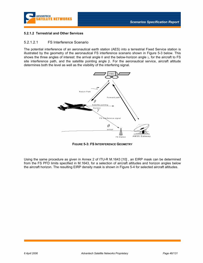
Scenarios Specification Report
6 April 2006 Advantech Satellite Networks Proprietary Page 46/131
5.2.1.2 Terrestrial and Other Services
5.2.1.2.1 FS Interference Scenario
The potential interference of an aeronautical earth station (AES) into a terrestrial Fixed Service station is illustrated by the geometry of the aeronautical FS interference scenario shown in Figure 5-3 below. This shows the three angles of interest: the arrival angle θ and the below-horizon angle γ, for the aircraft to FS site interference path, and the satellite pointing angle β. For the aeronautical service, aircraft altitude determines both the level as well as the visibility of the interfering signal.
A M S S G a te w a y
F S S
R e tu rn P a th
F o rw a rd p a th
H o r iz o n
F S In te r fe re n c e s ig n a l
θ
θ
γ
β
a rr iv a l
S a te lli te p o in t in g
F S S ta tio n
FIGURE 5-3: FS INTERFERENCE GEOMETRY
Using the same procedure as given in Annex 2 of ITU-R M.1643 [10] , an EIRP mask can be determined from the FS PFD limits specified in M.1643, for a selection of aircraft altitudes and horizon angles below the aircraft horizon. The resulting EIRP density mask is shown in Figure 5-4 for selected aircraft altitudes.

Scenarios Specification Report
6 April 2006 Advantech Satellite Networks Proprietary Page 47/131
AES EIRP Mask for FS Interference Scenario
-50.0
-45.0
-40.0
-35.0
-30.0
-25.0
-20.0
-15.0
-10.0
-5.0
0.0
0 10 20 30 40 50 60 70 80 90
Horizon angle (degrees)
EIR
P (d
BW
/MH
z)
12 km altitude
6 km altitude
1 km altitude
0.5 km altitude
FIGURE 5-4: AES EIRP MASK FOR FS INTERFERENCE SCENARIO
The required isolation for the interference path is the difference between the AES on-axis EIRP and the required EIRP density mask for FS. The desired AES on-axis EIRP is the maximum permitted by the EIRP density mask for FSS as determined above depending on the effective aperture size, orbit spacing, and frequency band. For example, for a 3 degree Ku band satellite and AES antenna with 50 cm aperture, the on-axis EIRP is 33.8 dBW/40 kHz from Table 5-9 above, or 47.8 dBW/MHz in a 1 MHz bandwidth.
In general, the total isolation of this FS interference path will include AES antenna discrimination between the on-axis and horizon angle to the FS station, the distance spreading loss, any transmitter filtering between the wanted and interfering frequencies, and any obstruction losses by the aircraft itself. The required co-channel isolation is shown in Table 5-10 below calculated for the selected AES on axis EIRP and for a 12 km aircraft cruising altitude with the aircraft approaching the FS station first from its horizon to directly overhead the FS station.
TABLE 5-10: AES-FS INTERFERENCE PATH ISOLATION FOR 12KM CRUISING ALTITUDE
Horizon <γ
Arrival <θ
Distance d
Spreading loss
PFD EIRP mask Required Isolation
Antenna Isolation
Extra Isolation
Deg deg km dB dBW/(m2 .1 MHz)
dBW/1MHz dB dB dB
3.52 0.3 363.9 122.2 -131.9 -9.7 57.5 36.3 19.310 9.4 71.3 108.0 -127.3 -19.3 67.1 42.8 22.540 39.9 18.7 96.4 -112.1 -15.6 63.4 42.8 18.8
90.0 90.0 12.0 92.6 -112.0 -19.4 67.2 30.8 34.7
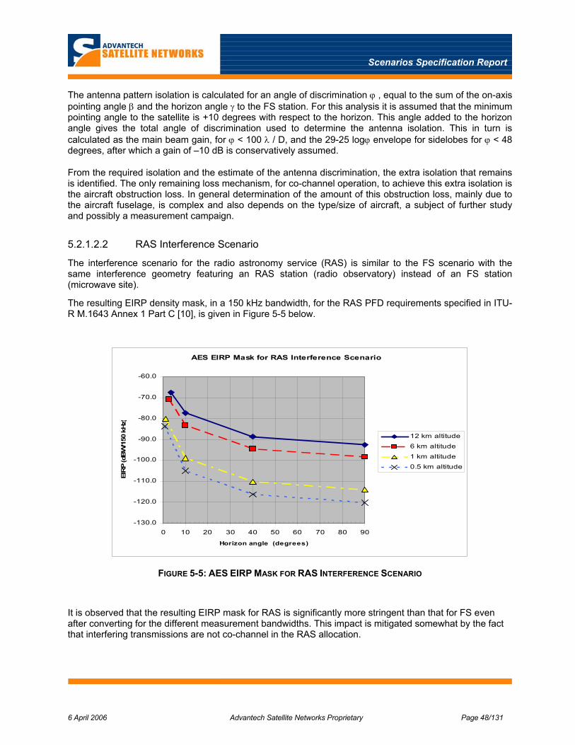
Scenarios Specification Report
6 April 2006 Advantech Satellite Networks Proprietary Page 48/131
The antenna pattern isolation is calculated for an angle of discrimination ϕ , equal to the sum of the on-axis pointing angle β and the horizon angle γ to the FS station. For this analysis it is assumed that the minimum pointing angle to the satellite is +10 degrees with respect to the horizon. This angle added to the horizon angle gives the total angle of discrimination used to determine the antenna isolation. This in turn is calculated as the main beam gain, for ϕ < 100 λ / D, and the 29-25 logϕ envelope for sidelobes for ϕ < 48 degrees, after which a gain of –10 dB is conservatively assumed.
From the required isolation and the estimate of the antenna discrimination, the extra isolation that remains is identified. The only remaining loss mechanism, for co-channel operation, to achieve this extra isolation is the aircraft obstruction loss. In general determination of the amount of this obstruction loss, mainly due to the aircraft fuselage, is complex and also depends on the type/size of aircraft, a subject of further study and possibly a measurement campaign.
5.2.1.2.2 RAS Interference Scenario
The interference scenario for the radio astronomy service (RAS) is similar to the FS scenario with the same interference geometry featuring an RAS station (radio observatory) instead of an FS station (microwave site).
The resulting EIRP density mask, in a 150 kHz bandwidth, for the RAS PFD requirements specified in ITU-R M.1643 Annex 1 Part C [10], is given in Figure 5-5 below.
AES EIRP Mask for RAS Interference Scenario
-130.0
-120.0
-110.0
-100.0
-90.0
-80.0
-70.0
-60.0
0 10 20 30 40 50 60 70 80 90
Horizon angle (degrees)
EIR
P (d
BW
/150
kH
z)
12 km altitude6 km altitude
1 km altitude0.5 km altitude
FIGURE 5-5: AES EIRP MASK FOR RAS INTERFERENCE SCENARIO
It is observed that the resulting EIRP mask for RAS is significantly more stringent than that for FS even after converting for the different measurement bandwidths. This impact is mitigated somewhat by the fact that interfering transmissions are not co-channel in the RAS allocation.
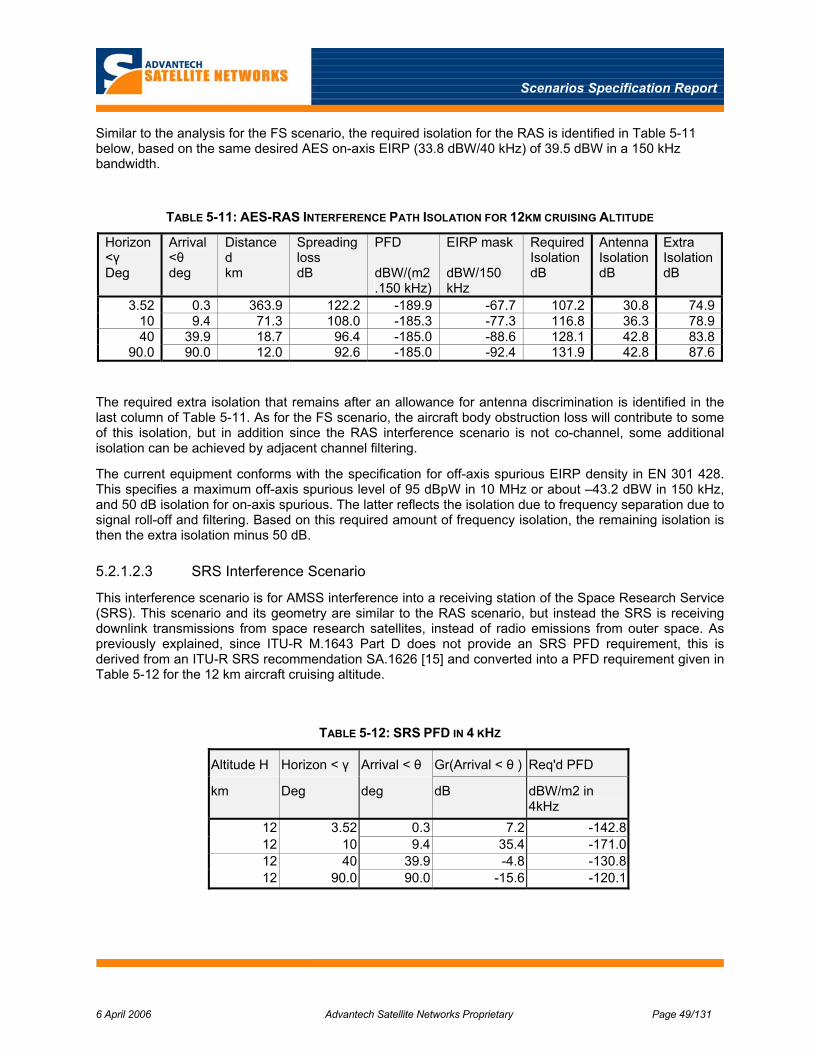
Scenarios Specification Report
6 April 2006 Advantech Satellite Networks Proprietary Page 49/131
Similar to the analysis for the FS scenario, the required isolation for the RAS is identified in Table 5-11 below, based on the same desired AES on-axis EIRP (33.8 dBW/40 kHz) of 39.5 dBW in a 150 kHz bandwidth.
TABLE 5-11: AES-RAS INTERFERENCE PATH ISOLATION FOR 12KM CRUISING ALTITUDE
Horizon <γ
Arrival <θ
Distance d
Spreading loss
PFD EIRP mask Required Isolation
Antenna Isolation
Extra Isolation
Deg deg km dB dBW/(m2 .150 kHz)
dBW/150 kHz
dB dB dB
3.52 0.3 363.9 122.2 -189.9 -67.7 107.2 30.8 74.910 9.4 71.3 108.0 -185.3 -77.3 116.8 36.3 78.940 39.9 18.7 96.4 -185.0 -88.6 128.1 42.8 83.8
90.0 90.0 12.0 92.6 -185.0 -92.4 131.9 42.8 87.6
The required extra isolation that remains after an allowance for antenna discrimination is identified in the last column of Table 5-11. As for the FS scenario, the aircraft body obstruction loss will contribute to some of this isolation, but in addition since the RAS interference scenario is not co-channel, some additional isolation can be achieved by adjacent channel filtering.
The current equipment conforms with the specification for off-axis spurious EIRP density in EN 301 428. This specifies a maximum off-axis spurious level of 95 dBpW in 10 MHz or about –43.2 dBW in 150 kHz, and 50 dB isolation for on-axis spurious. The latter reflects the isolation due to frequency separation due to signal roll-off and filtering. Based on this required amount of frequency isolation, the remaining isolation is then the extra isolation minus 50 dB.
5.2.1.2.3 SRS Interference Scenario
This interference scenario is for AMSS interference into a receiving station of the Space Research Service (SRS). This scenario and its geometry are similar to the RAS scenario, but instead the SRS is receiving downlink transmissions from space research satellites, instead of radio emissions from outer space. As previously explained, since ITU-R M.1643 Part D does not provide an SRS PFD requirement, this is derived from an ITU-R SRS recommendation SA.1626 [15] and converted into a PFD requirement given in Table 5-12 for the 12 km aircraft cruising altitude.
TABLE 5-12: SRS PFD IN 4 KHZ
Altitude H Horizon < γ Arrival < θ Gr(Arrival < θ ) Req'd PFD
km Deg deg dB dBW/m2 in 4kHz
12 3.52 0.3 7.2 -142.8 12 10 9.4 35.4 -171.0 12 40 39.9 -4.8 -130.8 12 90.0 90.0 -15.6 -120.1

Scenarios Specification Report
6 April 2006 Advantech Satellite Networks Proprietary Page 50/131
Based on this PFD calculation, the resulting EIRP mask can be determined in the same way as for FS and RAS services. The resulting EIRP density mask is shown in Figure 5-6 below. The increased sensitivity at 10 degrees is due to the SRS station antenna pointing angle being set at 10 degrees elevation.
AES EIRP Mask for SRS Interference Scenario
-120.0
-110.0
-100.0
-90.0
-80.0
-70.0
-60.0
-50.0
-40.0
-30.0
0 10 20 30 40 50 60 70 80 90
Horizon angle (degrees)
EIR
P (d
BW
/4 k
Hz)
12 km altitude6 km altitude1 km altitude0.5 km altitude
FIGURE 5-6: EIRP MASK FOR SRS
The interference scenario for the Space Research service is somewhat similar to the RAS scenario but not as stringent. However, the SRS spectrum allocation is larger than RAS, which may have a greater operational impact in the future.
The isolation required to meet this SRS EIRP density mask is then determined and the resulting extra isolation after the AMSS antenna discrimination is subtracted is calculated and identified in Table 5-13 below. This shows that the extra co-channel isolation ranges from about 9 dB to 51 dB at a cruising altitude, with the maximum occurring when flying through the SRS antenna main lobe.
TABLE 5-13: AES-SRS INTERFERENCE PATH ISOLATION FOR 12KM CRUISING ALTITUDE
Horizon <γ
Arrival <θ
Distance d
Spreading loss
PFD EIRP mask Required Isolation
Antenna Isolation
Extra Isolation
Deg deg km dB dBW/(m2 .4 kHz)
dBW/4 kHz dB dB dB
3.52 0.3 363.9 122.2 -142.8 -20.6 44.4 30.8 13.610 9.4 71.3 108.0 -171.0 -63.0 86.8 36.3 50.540 39.9 18.7 96.4 -130.8 -34.4 58.2 42.8 15.4
90.0 90.0 12.0 92.6 -120.1 -27.5 51.3 42.8 8.5
Scenarios Specification Report
6 April 2006 Advantech Satellite Networks Proprietary Page 51/131
5.2.2 Maritime
For the maritime mobile satellite service (MMSS), the specific regulatory requirements are given in EN 301 427 [9], for low bit rate mobile, however in general the requirements of the AMSS are assumed to apply to broadband maritime applications with some specific constraints as noted below. The impact of the FSS interference scenario is also essentially the same, while those of the other terrestrial services will be less an impact or even negligible due to the reduced visibility and non proximity to those terrestrial sites in general.
Additional specific constraints to the MMSS are given in ITU-R Resolution 902 which state provisions relating to Earth Stations located on board Vessels (ESV) which operates in fixed-satellite service networks in the uplink bands 5925-6425 MHz and 14-14.5 GHz.
From this resolution, two main constraints for ESV terminal:
1. The ESV terminal shall have an antenna greater than 1.2 m aperture (possible 0.6 m if agreed by the administration)
2. Emission should be ceased if the distance towards the coastal line in lower than 125 km without prior agreement of the concerned administration. Any transmissions from ESVs within the minimum distances shall be subject to the prior agreements of the concerned administration
Since the maritime antenna aperture will in general be larger than 0.6 m, the antenna system with suitable stabilisation and tracking should achieve sufficient antenna sidelobe discrimination to minimise interference levels enough to avoid the need for any additional interference techniques. For the interference scenarios with terrestrial services, the 125 km coastal limit should avoid this interference for most cases, otherwise exclusions zones would need to be applied.
5.2.3 Land Mobile
As for the MMSS, while the specific regulatory requirements for the low data rate land mobile satellite service (LMSS) is specified in EN 301 427 [9], the AMSS requirements for broadband mobile are assumed to apply here as well. As for MMSS, the FSS scenario is the same as AMSS.
However, the terrestrial interference scenarios are similar to the aeronautical scenarios, since the land mobile station could be in proximity to a terrestrial FS or scientific station but in general at ground level instead of at an altitude.
The needed interference mitigation techniques are therefore expected to be essentially the same as for the aeronautical service, by employing spectrum spreading for the FSS scenarios and exclusion zones for the terrestrial scenarios.
5.3 Terrestrial Gapfiller Regulatory Environment
In general, a terrestrial gapfiller network is used in a mobile satellite system to “fill-in” the gaps in the satellite coverage due to natural or manmade obstructions such as mountains or tunnels. As is described in section 11 of this report, there are in general three main types of such gapfiller networks, including: an integral gapfiller, an external gapfiller and a hybrid of these two.
The external gapfiller refers to an existing 3G/4G terrestrial mobile services network such as UMTS or WLAN which operates independently from the satellite network in its own frequency allocations and regulations.
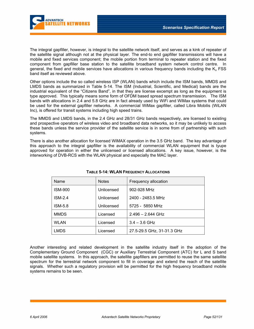
Scenarios Specification Report
6 April 2006 Advantech Satellite Networks Proprietary Page 52/131
The integral gapfiller, however, is integral to the satellite network itself, and serves as a kink of repeater of the satellite signal although not at the physical layer. The end-to end gapfiller transmissions will have a mobile and fixed services component; the mobile portion from terminal to repeater station and the fixed component from gapfiller base station to the satellite broadband system network control centre. In general, the fixed and mobile services have allocations in various frequency bands including the Ku FSS band itself as reviewed above.
Other options include the so called wireless ISP (WLAN) bands which include the ISM bands, MMDS and LMDS bands as summarized in Table 5-14. The ISM (Industrial, Scientific, and Medical) bands are the industrial equivalent of the “Citizens Band”, in that they are license excempt as long as the equipment is type approved. This typically means some form of OFDM based spread spectrum transmission. The ISM bands with allocations in 2.4 and 5.8 GHz are in fact already used by WiFi and WiMax systems that could be used for the external gapfiller networks. A commercial WiMax gapfiller, called Libra Mobilis (WiLAN Inc), is offered for transit systems including high speed trains.
The MMDS and LMDS bands, in the 2.4 GHz and 28/31 GHz bands respectively, are licensed to existing and prospective operators of wireless video and broadband data networks, so it may be unlikely to access these bands unless the service provider of the satellite service is in some from of partnership with such systems.
There is also another allocation for licensed WiMAX operation in the 3.5 GHz band. The key advantage of this approach to the integral gapfiller is the availability of commercial WLAN equipment that is tyupe approved for operation in either the unlicensed or licensed allocations. A key issue, however, is the interworking of DVB-RCS with the WLAN physical and especially the MAC layer.
TABLE 5-14: WLAN FREQUENCY ALLOCATIONS
Name Notes Frequency allocation
ISM-900
ISM-2.4
ISM-5.8
Unlicensed
Unlicensed
Unlicensed
902-928 MHz
2400 - 2483.5 MHz
5725 - 5850 MHz
MMDS Licensed 2.496 – 2.644 GHz
WLAN Licensed 3.4 – 3.6 GHz
LMDS Licensed 27.5-29.5 GHz, 31-31.3 GHz
Another interesting and related development in the satellite industry itself in the adoption of the Complementary Ground Component (CGC) or Auxiliary Terrestrial Component (ATC) for L and S band mobile satellite systems. In this approach, the satellite gapfillers are permitted to reuse the same satellite spectrum for the terrestrial network component to fill in coverage and extend the reach of the satellite signals. Whether such a regulatory provision will be permitted for the high frequency broadband mobile systems remains to be seen.
Scenarios Specification Report
6 April 2006 Advantech Satellite Networks Proprietary Page 53/131
5.4 Interference Mitigation Techniques
In this section, some comments are given on the potential measures to mitigate both the FSS and other interference scenarios identified above. The physical layer impairments due to these interference scenarios will be analyzed further under WP 1.2 in conjunction with the link budget analysis.
5.4.1 FSS Interference Mitigation
Sharing of the FSS on a secondary basis effectively places the equivalent requirement of fixed stations onto the mobile terminals; namely to operate within the EIRP density limits which in turn impacts on antenna pointing and sidelobe performance. In general, the regulations for Ku band require operation based on 3-degrees adjacent satellite spacing for Europe and Asia and 2 degrees for North America. For Ka band, 2 degrees is universally required.
The need for interference mitigation depends critically on the aperture size and the required EIRP density mask. The latter is in turn critically dependant on the satellite orbit spacing; for a 2 degree spacing the EIRP density mask is 8 dB lower than that for 3 degrees. Since mobile applications will use a range of antenna sizes, interference mitigation using spectrum spreading techniques will be required for effective apertures below a certain size.
While spreading is employed for the return path to prevent interference into adjacent FSS satellites, spreading may also be required in some scenarios, for the forward path to reduce susceptibility to downlink interference from adjacent satellites. However, the DVB-S2 transmission scheme is itself capable of a low spectral density in its most power efficient mode using QPSK and rate ¼ LDPC coding.
5.4.2 Terrestrial / Other Interference Mitigation
Sharing with the other terrestrial and satellite feeder link services is considerably more difficult due to the stringent flux density requirements when within proximity of these sites, as revealed by the analysis of these interference scenarios above.
The operational impact of these interference scenarios is mitigated somewhat by the fact that these sites are highly localised in geographic location, RF frequency, and in some cases time of operation. Sharing with these services on a secondary basis, in particular the Radio Astronomy and Space Research Services, require that interference to these sites be avoided by either stopping all mobile broadband transmissions within a defined exclusion zone or by changing frequencies.
To achieve this mitigation, the mobile terminal can be equipped with a database of these sites and exclusion zones and perform real-time calculations as required. Once the zones are passed, the terminal can re-login to the network and resume transmission.
5.5 Other Regulatory Issues
Besides the regulations that govern the actual emissions from the terminals, a number of regulatory regimes exist for issues such as safety, environmental conditions and electromagnetic compatibility with other on-board equipment. While these regulations are not expected to influence the system design directly, they may have indirect impacts because of their significant consequences for many implementation aspects. Examples of such indirect impacts include possible limitations on the choice of components for the terminals, which in turn may limit for example the amount of real-time processing that can be accommodated. These regulations and their impacts will be considered as appropriate as part of the work towards a standard for mobile applications, and are summarised here for completeness.

Scenarios Specification Report
6 April 2006 Advantech Satellite Networks Proprietary Page 54/131
5.5.1 Aeronautical
On-board aircraft, equipment that is not required for safety of the flight is covered by FAA TSO (Federal Aviation Administration Technical Standard Order) C138 [17]. Examples of equipment covered by this include in-flight entertainment systems and passenger-area local area network computers. TSO-C138 does not in itself contain technical requirements, but defines them by reference to other standards. The main standard for environmental requirements is RTCA (Radio Technical Commission for Aeronautics) DO-160 [18] . Non-essential equipment only needs to meet some of the safety-related requirements of DO-160; implementers will however typically want to meet more than the minimum set of requirements, in order to ensure the actual operation of the equipment.
There are also standards governing the design and implementation process for hardware [19] and software [20] in aeronautical terminals. These are not expected to have any major impact on the system being considered here.
5.5.2 Maritime
Environmental requirements for shipborne electronic equipment are defined in IEC standard 60945 [21]. For equipment that is not essential to safe navigation, only the EMC requirements of IEC 60945 apply. However, as for the aeronautical environment, it may be desirable to meet a number of the other requirements, in order to ensure that the terminal will actually work aboard the vessel.
The EMC requirements are generally less stringent than those for aeronautical applications, except in certain marine VHF bands. Most other requirements (temperature, humidity, atmosphere, electrostatic discharge etc.) are also less stringent than those for aeronautical equipment. The indirect impacts of these requirements (e.g., on processing power) will therefore also likely be correspondingly smaller.
5.5.3 Land
The environmental and EMC regulatory environment appears to be less developed for land-mobile environments than for maritime and aeronautical applications. A standard for trains does however exist [22]. This is a purely environmental standard; it does not contain EMC requirements.
The vibration and shock requirements for the railway environments are harder than those for the selected aeronautical environment, although not dramatically so. Other environmental requirements such as salt fog, sand, dust and rain are similar to or slightly less stringent than those for aeronautical terminals. It is therefore expected that the indirect impacts of these issues on the envisaged mobile standard will be similar to those discussed for the aeronautical terminals.

Scenarios Specification Report
6 April 2006 Advantech Satellite Networks Proprietary Page 55/131
6 CHANNEL MODELS
The candidate frequency bands for the extension of DVB-RCS fully to support mobility are Ku-band (10-14 GHz) and Ka-Band (20-30 GHz).
As a first qualitative analysis, the following classification can be proposed for the different mobile environments to be considered within the present study:
• Low-fading scenarios (almost always LOS or close to LOS conditions), such as aeronautical and maritime
• Strong-fading scenarios (frequent / deep / long signal blockages), such as land vehicular and railway
This chapter will propose and justify the selection of adequate channel models for all the scenarios listed above.
6.1 Brief Review of Non Frequency Selective Single and Multi State Channel Models
An important issue that needs to be addressed concerns the frequency selectivity of the propagation channels under consideration. It is common use in the literature to adopt the terminology “narrowband channel” to denote a channel characterised by flat frequency fading and “wideband channel” for a channel with frequency selectivity. As shown next, this linguistic equivalence, which holds quite well for lower frequency bands, where omni-directional antennas are normally employed, is in our view misleading when we start considering higher frequency bands such as Ku and above.
Formally, a communication channel is defined selective in frequency if the Coherence Bandwidth Bc is lower or comparable to the signal bandwidth Bs. By denoting with ( ),h t τ the Impulse Response of a
randomly time-varying linear channel, and by ( ) ( ), ,H t f h tτ τ⎡ ⎤⎣ ⎦F the Time-Varying Transfer Function, the coherence bandwidth is a measure of the “broadness” of the Frequency-Spaced Correlation Function
( ) ( ) 0,H H t
P f P t f∆ =
∆ ∆ ∆ . The latter can be derived from the Frequency-Spaced Time-Spaced Correlation
Function ( ) ( ) ( )*1 2 1 2 1 1 2 2, , , , ,HP t t f f H t f H t f⎡ ⎤
⎣ ⎦E , bearing in mind that under the WSS (Wide Sense
Stationary) and US (Uncorrelated Scattering) assumptions [43], ( ).HP does not depend on the initial time and frequency t1 and f1, but only on the differences 2 1t t t∆ = − and 2 1f f f∆ = − .
TABLE 6-1: COHERENCE BANDWIDTH MEASUREMENTS WITH OMNIDIRECTIONAL ANTENNAS
Environment Coherence Bandwidth Carrier Frequency
Highway 11.6 MHz
Rural 8.7 MHz
Urban LOS 11.3 MHz
1.82 GHz
All 30 MHz 40.1 GHz

Scenarios Specification Report
6 April 2006 Advantech Satellite Networks Proprietary Page 56/131
In practice, frequency selectivity implies that different frequent components of the received signal undergoes attenuation levels which are highly uncorrelated, thus provoking corresponding distortion of the received signal, unless suitable equalisation techniques are used. In the time domain, frequency selectivity corresponds to a dispersive behaviour associated with presence of diffuse components (signal echoes) reaching the receiver with a significant relative delay in comparison to the duration of the signal pulse Ts = 1 / Bs.
From direct measurements performed at L (1.82 GHz) and EHF (40.1 GHz) bands [44], summarised in Table 6-1, values for the coherence bandwidth Bc in the range of respectively 10 and 30 MHz were found. In the latter case, an antenna with hemispherical characteristics was used to detect a larger amount of signal echoes. Keeping in mind that highly directive antennas are used in practical cases at Ku band and above, echoes with significant power and delay are in most of the practical cases filtered out by the antenna radiation pattern. Therefore, the assumption of frequency non-selective channel holds at carrier frequencies higher or equal than Ku -Band for signals with data rate up to several tens of Mb/s and will be used throughout this chapter.
Under this assumption, ( ) ( ) ( ) ( ), j th t R t e θτ δ τ≈ , where ( )R t is now a random process representing the amplitude of the fading envelope of the received signal. As pointed out above, this is tantamount to assuming that the channel is non-dispersive in time, i.e. diffuse components (echoes) can not be distinguished from the direct signal, since their relative delay is negligible in comparison to the duration of the signal pulse Ts = 1 / Bs.
Several types of statistical models have been proposed in the literature to describe the behaviour of satellite channels under non-frequency selectivity conditions. The first class of models attempts to model the recorded data by means of a suitable Probability Density Function (PDF) ( )Rp r , such as the well-known Loo [45] and Suzuki distributions [46]. This approach, that can accurately represent the behaviour of the channel in homogenous environments such as maritime and aeronautical, is generally not satisfactory when sudden and substantial modifications in the propagation conditions occur, e.g. in the case of the land mobile satellite channel and particularly if fast-moving terminals are considered.
A second class of models is constituted by multi-state Markov chain based models [47]. This kind of model is based on the assumption that one Markov state is related to a particular propagation condition. For example, the traditional Lutz model [47] infers that two states have to be considered: a Line of Sight (LOS) state, where no obstacles between the satellite and the mobile terminal are present and a non-LOS (NLOS) state, where no direct visibility can be accounted for. According to this class of models, the amplitude of the fading envelope ( )R t is divided into fast and slow fading. Slow fading events, normally due to large obstacles, are modelled as a finite state machine. Fast fading events, due to the irregularity of the obstacles (e.g. vegetative shadowing) and to the multipath propagation phenomenon can be additionally modelled as superimposed random variations that follow a given PDF for each state. The overall PDF describing the fading envelope amplitude can hence be written as
( ) ( ),1
N
R k R kk
p r p rπ=
=∑ (6.1)
where N is the number of states, kπ the absolute probability of being in the state k (that can easily be
obtained from the State Transition Matrix ijp⎡ ⎤= ⎣ ⎦S , containing in each element the probability of transition
from state i to state j) and ( ),R kp r the PDF associated to the fast fading within state k.
A more exhaustive review of the characterisation of time-varying linear propagation channels can be found in [48].
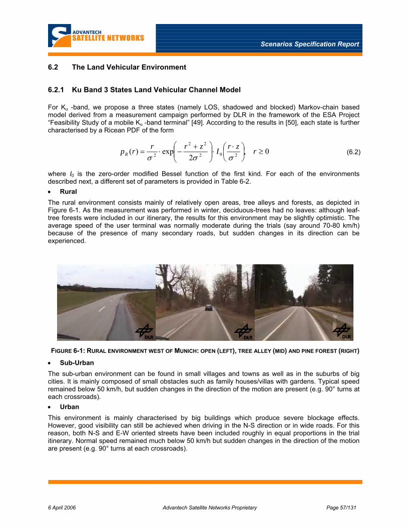
Scenarios Specification Report
6 April 2006 Advantech Satellite Networks Proprietary Page 57/131
6.2 The Land Vehicular Environment
6.2.1 Ku Band 3 States Land Vehicular Channel Model
For Ku -band, we propose a three states (namely LOS, shadowed and blocked) Markov-chain based model derived from a measurement campaign performed by DLR in the framework of the ESA Project “Feasibility Study of a mobile Ku -band terminal” [49]. According to the results in [50], each state is further characterised by a Ricean PDF of the form
0,2
exp)( 202
22
2 ≥⎟⎠⎞
⎜⎝⎛ ⋅
⋅⎟⎟⎠
⎞⎜⎜⎝
⎛ +−⋅= rzrIzrrrpR σσσ
(6.2)
where I0 is the zero-order modified Bessel function of the first kind. For each of the environments described next, a different set of parameters is provided in Table 6-2. • Rural The rural environment consists mainly of relatively open areas, tree alleys and forests, as depicted in Figure 6-1. As the measurement was performed in winter, deciduous-trees had no leaves: although leaf-tree forests were included in our itinerary, the results for this environment may be slightly optimistic. The average speed of the user terminal was normally moderate during the trials (say around 70-80 km/h) because of the presence of many secondary roads, but sudden changes in its direction can be experienced.
FIGURE 6-1: RURAL ENVIRONMENT WEST OF MUNICH: OPEN (LEFT), TREE ALLEY (MID) AND PINE FOREST (RIGHT) • Sub-Urban The sub-urban environment can be found in small villages and towns as well as in the suburbs of big cities. It is mainly composed of small obstacles such as family houses/villas with gardens. Typical speed remained below 50 km/h, but sudden changes in the direction of the motion are present (e.g. 90° turns at each crossroads). • Urban This environment is mainly characterised by big buildings which produce severe blockage effects. However, good visibility can still be achieved when driving in the N-S direction or in wide roads. For this reason, both N-S and E-W oriented streets have been included roughly in equal proportions in the trial itinerary. Normal speed remained much below 50 km/h but sudden changes in the direction of the motion are present (e.g. 90° turns at each crossroads).

Scenarios Specification Report
6 April 2006 Advantech Satellite Networks Proprietary Page 58/131
• Highway The highway environment resembles an open area apart from the presence of relatively frequent bridges and tunnels. Also, the higher terminal speed (during our trial, a maximum speed of 120 km/h was experienced) will produce a greater Doppler effect, although the direction of the motion can remain constant for longer time intervals. Big national roads can also be included in this environment. Both N-S and E-W oriented highways have been included in our itinerary.
FIGURE 6-2: SUB-URBAN (LEFT), URBAN (MID) AND HIGHWAY (RIGHT) ENVIRONMENTS IN AND AROUND MUNICH
For each of the environments, the State Transition Matrix has been computed (elements with row and column index i and j respectively denote the probability to go from state i to state j). From the State Transition Matrix, the absolute probability S of being in a certain state can easily be computed.
The state transition period (also called state duration) is equal to 0.0417 s, corresponding to blocks of 1000 samples at the sampling frequency of 24 kHz. The above mentioned state duration refers to average speeds of 100, 70, 40 and 30 km/h for the highway, rural, suburban and urban environments respectively. Should different average speeds be considered, the state durations are scaled linearly.
TABLE 6-2: KU-BAND LAND VEHICULAR CHANNEL MODEL PARAMETERS
Environment State Transition Matrix S Rice σ Rice z Rice Factor Mean
0.9862 0.0138 0.0000 0.8922 0.0947 0.9892
0.1499 0.8378 0.0123 0.0823 0.3010 0.3510
Highway
0.0008 0.0396 0.9596 0.0255 0.0505 0.0000
17 dB
-1.6 dB
0 dB
-9 dB
-23 dB
0.9795 0.0204 0.0001 0.7844 0.0916 0.9976
0.1007 0.8277 0.0716 0.1555 0.2464 0.4020
Rural
0.0010 0.1813 0.8177 0.0600 0.0993 0.0000
17 dB
1.2 dB
0 dB
-8 dB
-17 dB
0.9796 0.0204 0.0000 0.7831 0.0829 0.9994
0.0929 0.8571 0.0500 0.1715 0.2289 0.4393
Suburban
0.0015 0.1876 0.8109 0.0454 0.1054 0.0000
18 dB
2.6 dB
0 dB
-7 dB
-17 dB
0.9902 0.0098 0.0001 0.6025 0.0926 0.9936
0.0714 0.8756 0.0529 0.0825 0.1900 0.4132
Urban
0.0000 0.0140 0.9860 0.3150 0.0610 0.0000
17 dB
3.7 dB
0 dB
-7 dB
-21 dB

Scenarios Specification Report
6 April 2006 Advantech Satellite Networks Proprietary Page 59/131
6.2.2 Ka Band 3 States Land Vehicular Channel Model
Also for Ka-band, we propose a three states (namely LOS, shadowed and blocked) Markov-chain based model derived from a measurement campaign performed in the framework of the ESA Project “Land mobile satellite narrowband propagation measurement campaign at Ka -band”. Results were published in [51] and [52]. Each state is in this case further characterised by a Loo distribution. Whereas the Rice distribution arises by assuming that ( ) ( ) ( ) ( ) ( )j t
kh t R t e x t jy t zθ= = + + , with x and y being independent Gaussian processes with zero mean and variance σk, and zk being a constant value for each state k, the Loo distribution arises under the additional assumption that zk follows a lognormal distribution with parameters µk and ζk:
( ) ( ) ( )
( )
( ) ( ) ( )0 0 0
0
2 2 20 0 0
0 02 2 2200
ln1 exp2 22
k k kLoo Rice k Lognormal
k
k k kk k
p r p r z z p z dz
z r z rzr I dzz
µζ σ σπζ σ
∞
∞
= = ⋅ =
⎛ ⎞− ⎛ ⎞+⎜ ⎟− − ⋅ ⎜ ⎟⎜ ⎟ ⎝ ⎠⎝ ⎠
∫
∫ (6.3)
where I0 is the zero-order modified Bessel function of the first kind. This model considers five different environments, namely rural with leaf trees, rural with pine trees, rural with tree alley, suburban and urban, for which the parameters of the Loo distribution are shown in Table 6-3.
The following relations hold:
( ) ( ) ( )210 10 10( ) 20log , ( ) 20log , ( ) 10log 2 .dB e dB e MP dBµ ζα σ= Ψ = = (6.4)
TABLE 6-3: LOO DISTRIBUTION PARAMETERS TAKEN FROM [52]
Furthermore, six different possible orientations of the road with respect to the satellite position are considered within this model, as detailed in Table 6-4 where the State Transition Matrixes for the five environments listed in Table 6-3 are reported.

Scenarios Specification Report
6 April 2006 Advantech Satellite Networks Proprietary Page 60/131
TABLE 6-4: KA-BAND LAND VEHICULAR CHANNEL MODEL STATE TRANSITION MATRIXES TAKEN FROM [52]

Scenarios Specification Report
6 April 2006 Advantech Satellite Networks Proprietary Page 61/131
6.2.3 A Comparison of the 1st and 2nd Order Statistics Obtained by the Above Models
To allow a better comparison with the previous channel model at Ku -band, the approach followed in [53] is to average the parameters in Table 6-3 and Table 6-4 for the three different sub-types of rural environments and the six different possible orientations. Models for the suburban and urban environments can be directly compared, whereas a specific model for the highway is unfortunately only available at Ku -band.
The Complementary Cumulative Distribution Functions, defined as ( ) ( ) 1-CDF Probx R t x= ≥ , are presented in Figure 6-3 for the rural and urban environments at Ku, Ka and EHF (40.1 GHz) bands using the 2 models described in the previous section and the model in [44] for the EHF band.
-40 -35 -30 -25 -20 -15 -10 -5 00
0.1
0.2
0.3
0.4
0.5
0.6
0.7
0.8
0.9
1
Signal Level [dB]
Com
plem
enta
ry C
DF
Urban Environment
Ku-BandKa-BandEHF Band
-40 -35 -30 -25 -20 -15 -10 -5 00
0.1
0.2
0.3
0.4
0.5
0.6
0.7
0.8
0.9
1
Signal Level [dB]
Com
plem
enta
ry C
DF
Rural Environment
Ku-BandKa-BandEHF Band
FIGURE 6-3: COMPLEMENTARY CDFS FOR THE LMSC AT KU, KA AND EHF BANDS TAKEN FROM [53]
As it can be noticed, the behaviour of the propagation channel tends to become closer to an on-off channel, especially in the urban environment, as the carrier frequency increases. At EHF band, this is also a consequence of the fact that a two state only model has been considered. Nevertheless, the same effect can be noticed by comparing the results for Ku and Ka bands, where both models have three states. By inspecting the complementary CDFs in the rural case, it can be noticed how the effect of vegetative shadowing tends to become more noticeable as the carrier frequency increases: at Ku band, 90% link availability could be obtained with 10 dB margin, whereas between 15 and 20 dB are required at Ka band and more than 40 dB at EHF band. As already pointed out, in the urban case, where most of the fades are due to buildings, no such an effect can be appreciated and the channel tends to assume an on-off behaviour: around 30 dB margin are required in all cases to achieve 90% link availability.
6.2.4 Extension to the Railway Case
For the specific case of the railway environment, the presence of several metallic obstacles along the railroad like electrical trellises (Figure 6-4, left-uppermost), posts with horizontal brackets (Figure 6-4, left-lowermost), which may be often grouped together (Figure 6-4, rightmost) and catenaries, i.e. electrical cables, visible in all the aforementioned figures must be taken into account in addition to the presence of other “traditional” obstacles such as isolated buildings, bridges or trees that may appear along both normal roads and railway lines.

Scenarios Specification Report
6 April 2006 Advantech Satellite Networks Proprietary Page 62/131
Dedicated measurements were performed at Ku -Band in spring 2004 along the Italian railway in the framework of the EC co-funded project FIFTH [54]. As illustrated in Figure 6-5, catenaries resulted in a negligible attenuation of 2-3 dB (rightmost plot), thus almost negligible, where electrical trellises and posts with or without brackets result in deeper attenuations that, depending on the geometry and layout of the obstacles and on the orientation of the railway with respect to the position of the satellite, can even reach 15-20 dB. This kind of deterministic and (space) periodic fades can be superimposed on the aforementioned statistical models accounting for unpredictable obstacles [55].
FIGURE 6-4: NOMENCLATURE OF RAILWAY SPECIFIC OBSTACLES (LEFT) AND GEOMETRY OF THE KNIFE-EDGE DIFFRACTION APPLIED TO ELECTRICAL TRELLISES (RIGHT).
FIGURE 6-5: MEASURED ATTENUATION IN DECIBELS PRODUCED BY ELECTRICAL TRELLISES (LEFT), ELECTRICAL POSTS WITH BRACKETS (MID) AND CATENARIES (RIGHT) AT KU-BAND [54]
Even if the layout and exact geometry of the obstacles in Figure 6-4 can significantly change depending on the considered railway path, it turned out that the attenuation introduced by these kind of obstacles can be accurately modelled using knife-edge diffraction theory [55]: in the presence of an obstacle having one infinite dimension (e.g. mountains or high buildings), the knife-edge attenuation can be computed as the ratio between the received field in presence of the obstacle and the received field in free space conditions. In the case addressed here, as shown in Figure 6-4 (left), the obstacle has two finite dimensions, and the received field is hence the sum of the contributions coming from both sides of the obstacle. Therefore the resulting attenuation can be written as follows:
( ) ( )( ) ( )( )( )2 2)
2 21 2
max
1 2, ,2
K h dj v j v
sKh
a bA h G h e dv G h e dv Ka bG
π π
α αλ
−∞− −
−∞
⎛ ⎞ +⎜ ⎟= + =⎜ ⎟ ⋅⎝ ⎠
∫ ∫ (6.5)

Scenarios Specification Report
6 April 2006 Advantech Satellite Networks Proprietary Page 63/131
where λ is the wavelength, a is the distance between the receiving antenna and the obstacle, b is the distance between the obstacle and the satellite, h is the height of the obstacle above the LOS and d is the width of the obstacle. Finally, the usage of a directive antenna with radiation pattern G(α) has to be considered. This implies an additional attenuation due to the fact that, whenever the two diffracted rays reach the receiving antenna with angles α1 and α2 as shown in Figure 6-4, the antenna shows a gain less than the maximum achievable (Gmax) and depending on the variable h.
In the absence of a channel model directly extracted from measurements in the railway environment, it is common practice to model the Railroad Satellite Channel by superimposing (i.e. multiplying) the statistical fades reproduced by the Markov model ( )1R t (e.g. selecting at Ku -band the parameters corresponding to the highway, which is the most similar situation to a railway) with the space-periodic fades introduced by the electrical trellises ( )2 / trainR h v obtainable by means of the above equation. Values of the parameters in Figure 6-4, as well as the space separation between subsequent electrical trellises depend on the considered railway.
6.3 The Aeronautical Environment
6.3.1 Taxiway, Cruising, Ascent and Descent Flight Phases
Experimental results at 18.6 GHz [56] show that the channel behaves Ricean during normal flight situations and manoeuvres, with a Rice-factor well above 30 dB. Figure 6-6 shows a graph of a received power versus time during cruising together with the corresponding Ricean Probability Density Function (PDF). The corresponding Rice factor is in this case 34 dB.
Probability density functionRank 1 Eqn 8001 [UDF 1] y=Rice(a)
r^2=0.99003315 DF Adj r^2=0.98998281 FitStdErr=0.54211238 Fstat=19767.178a=2948.134
0.9 0.95 1 1.05 1.1 1.15received power
0
2.5
5
7.5
10
12.5
15
17.5
prob
abilit
y
FIGURE 6-6: RECEIVED POWER DURING CRUISING (LEFT) AND CORRESPONDING RICEAN PDF (RIGHT) [56]
6.3.2 Extreme Manoeuvres
Fades due to the aircraft structure were observed in case of extreme manoeuvres (see Figure 6-7). For a flight turn with roll angle about 20°, for instance, the reception level decreases during the inclination of the body of the airplane by approximately 3 dB, because the wing disturbs the reception of the signal. By making critical turns with roll angles about 45° (the satellite elevation was approximately 35°), a signal shadowing of up to 15 dB can be observed when the wing crosses the LOS. Lastly, in Figure 6-8 the aircraft flew in meanders like a wavy trajectory in line with the propagation path from the satellite. In this way the aircraft tail crossed the propagation path of the satellite signal periodically, causing diffraction and shadowing. The fade depth is about 2–3 dB. The period of the aircraft movement corresponds to the signal

Scenarios Specification Report
6 April 2006 Advantech Satellite Networks Proprietary Page 64/131
fades. These examples show that even in the rare case in which such fades may occur, they have a relatively slow dynamic of the order of seconds, i.e. comparable to that of rain fading.
FIGURE 6-7: SIGNAL FADES PROVOKED BY THE AIRCRAFT STRUCTURE (WING) DURING EXTREME MANOUVERS [56]
FIGURE 6-8: SIGNAL FADES AND AIRCRAFT ALTITUDE DURING MEANDER MANOUVERS [56]
6.4 The Maritime Environment
For the maritime case, no experimental results concerning propagation measurements at the frequencies of interest are available in the literature. Nevertheless, considering the usage of highly directive antennas, LOS conditions can be assumed and the channel considered as a pure Ricean channel with very high Rice factor, i.e. very close to a purely AWGN channel. A Rice Factor of 34 dB as for the aeronautical case appears a reasonable choice.
Given the relatively high carrier frequencies, the possibility of having significant reflections from the sea surface can be excluded (except for the unlikely case of very rough sea state) also for the worst case of very low elevation angles and for a mobile terminal located at sea level altitude. To confirm this statement, the upper and lower delimitation of the 3rd Fresnel zone, where 90% of the signal power is concentrated, has been plotted in Figure 6-9 for the worst case of a 10 GHz link. For the sake of clarity, a short explanation of Fresnel zones concept is provided next.
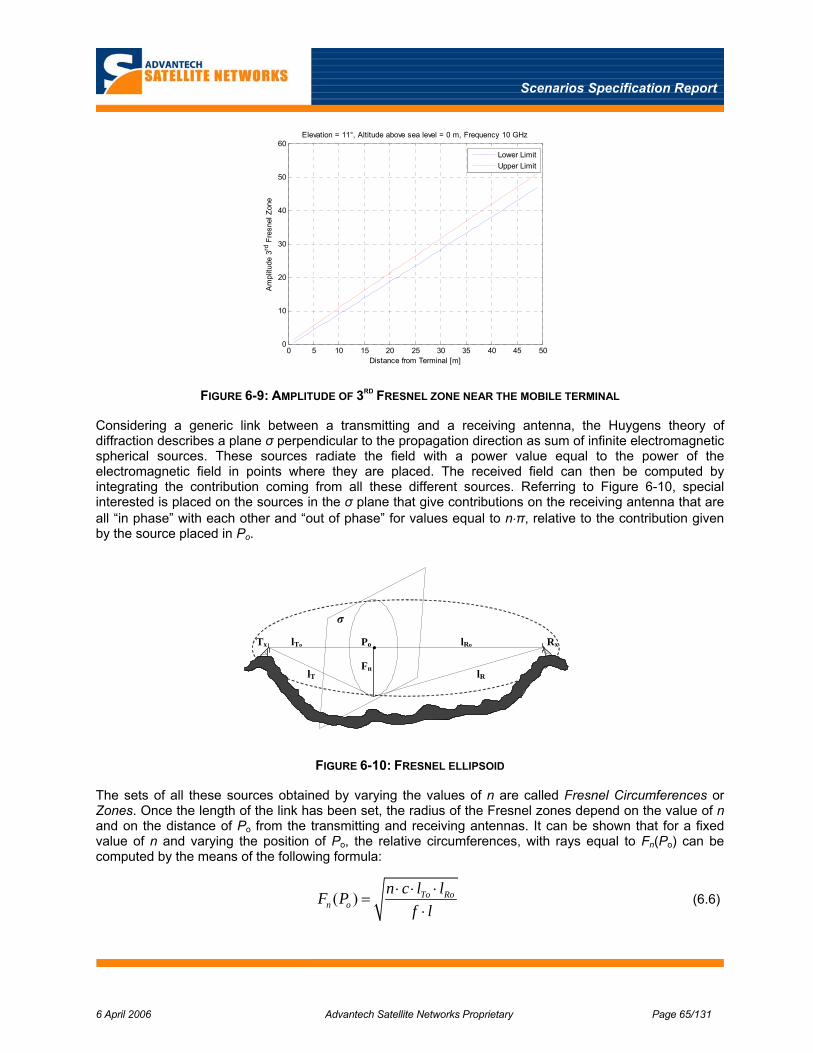
Scenarios Specification Report
6 April 2006 Advantech Satellite Networks Proprietary Page 65/131
0 5 10 15 20 25 30 35 40 45 500
10
20
30
40
50
60
Distance from Terminal [m]
Am
plitu
de 3
rd F
resn
el Z
one
Elevation = 11°, Altitude above sea level = 0 m, Frequency 10 GHz
Lower LimitUpper Limit
FIGURE 6-9: AMPLITUDE OF 3RD FRESNEL ZONE NEAR THE MOBILE TERMINAL
Considering a generic link between a transmitting and a receiving antenna, the Huygens theory of diffraction describes a plane σ perpendicular to the propagation direction as sum of infinite electromagnetic spherical sources. These sources radiate the field with a power value equal to the power of the electromagnetic field in points where they are placed. The received field can then be computed by integrating the contribution coming from all these different sources. Referring to Figure 6-10, special interested is placed on the sources in the σ plane that give contributions on the receiving antenna that are all “in phase” with each other and “out of phase” for values equal to n⋅π, relative to the contribution given by the source placed in Po.
Tx Rx Po
σ
Fn
lRo lTo
lR lT
.
FIGURE 6-10: FRESNEL ELLIPSOID
The sets of all these sources obtained by varying the values of n are called Fresnel Circumferences or Zones. Once the length of the link has been set, the radius of the Fresnel zones depend on the value of n and on the distance of Po from the transmitting and receiving antennas. It can be shown that for a fixed value of n and varying the position of Po, the relative circumferences, with rays equal to Fn(Po) can be computed by the means of the following formula:
( ) To Ron o
n c l lF Pf l
⋅ ⋅ ⋅=
⋅ (6.6)

Scenarios Specification Report
6 April 2006 Advantech Satellite Networks Proprietary Page 66/131
where f is the carrier frequency and c the speed of light.
6.5 Doppler Shift and Doppler Spread Estimation
An additional aspect of mobility is constituted by the Doppler shift df , i.e., a frequency shift proportional to the time derivative of the path delay, and corresponding to the integral mean of the Doppler Spectrum ( ) ( ) ( ) ( ) ( ), *S f F r t r t E h t h t t⎡ ⎤ ⎡ ⎤= ∆ ∆ = + ∆⎣ ⎦ ⎣ ⎦ , i.e. the Power Spectral Density of the fading process.
rp
rs
vz
vlong
α
FIGURE 6-11: POSITION OF TERMINAL AND SATELLITE RELATIVE TO EARTH
Referring to Figure 6-11, applicable without loss of generality also the maritime and land mobile cases, the
Doppler Shift Doppler Shift can be calculated as dd c
vf f
c= where cf is the carrier frequency, c is the
speed of light and the Doppler velocity
[ ] [ ] [ ]( )αββαββα
sincossincoscoscoscos21
22
⋅⋅⋅−⋅⋅+⋅⋅−⋅
⋅+⋅⋅⋅−
=
SlongSlatSPz
SSPP
D
rvrvrrvrrrr
v (6.7)
where rP is the radius of center of earth to the terminal, rS is radius of center of earth to the satellite, α is latitude, β is the longitude difference between the terminal and the GEO satellite orbital position, vlat is velocity in latitude direction (heading west is positive), vlong is velocity in longitude direction (heading south is positive velocity) and vZ is velocity in z-axis (height). The above equation can be also used to estimate
the Doppler Drift (or Differential Doppler) d d cdf dv fdt dt c
= . If a constant speed is assumed, cosD constv v α= ⋅
and hence sinDconst
dv dvdt dt
αα= ⋅ ⋅ .
For the specific case of aircraft in holding patterns (circular trajectory) at constant speed and constant
angular velocity, Dconst
U Turn
dv vdt T
π
−
= ⋅ , where TU-Turn is the time for the half-circle, equal to 1 minute for a
typical holding pattern.

Scenarios Specification Report
6 April 2006 Advantech Satellite Networks Proprietary Page 67/131
Table 6-5 gives some typical values in Ku band for Doppler shift, Doppler Drift and Time Drift, for different type of mobile terminals (speed and accelerations). The tables provide worst case Doppler shifts, assuming terminal motion towards the satellite and minimum elevation angle (leading to a relative angle between the vehicle and the satellite of 0°), for all considered system scenarios. The Doppler figures due to satellite motion are also included for reference. These values are commensurate with those presented in Annex L of [59] and used in previous investigations.
TABLE 6-5: WORST-CASE DOPPLER FIGURES AT KU-BAND
Type of Mobile Speed Acceleration (m/s2)
Doppler frequency variation
Doppler frequency shift
(Uplink)
Doppler frequency shift
(Downlink)Time drift
Frequency drift (UL)
Frequency drift (DL)
Maritime 25 km/h 5 m/s2 2,31E-08 336 Hz 295 Hz 23,1 ns/s 242 Hz/s 213 Hz/sVehicular (bus, car, truck) 120 km/h 10 m/s2 1,11E-07 1611 Hz 1417 Hz 111 ns/s 483 Hz/s 425 Hz/sTrain 350 km/h 5 m/s2 3,24E-07 4699 Hz 4132 Hz 324 ns/s 242 Hz/s 213 Hz/sAeronautical (< sound speed) 330 m/s 17 m/s2 1,10E-06 15950 Hz 14025 Hz 1100 ns/s 822 Hz/s 723 Hz/sSatellite movement (GSO) 3 m/s 0 m/s2 1,00E-08 145 Hz 128 Hz 10 ns/s 4,8 Hz/s 4,3 Hz/s
The integral RMS (root mean square) of the Doppler Spectrum, hereafter referred to as Doppler Spread
and defined as ( ) ( ) ( )22 / /f df f S f df S f dfσ+∞ +∞
−∞ −∞
= −∫ ∫ is another key parameter, since it is inversely
proportional to the Coherence Time Tc, representing the maximum time separation during which two samples of the fading process can be considered as highly correlated. Should Tc be lower than (or comparable to) the duration of the modulating pulse, the channel is said to be selective in time, and its dynamics are faster than the duration of one transmitted symbol. If Tc is greater than the duration of the modulating pulse, the channel can be assumed stationary within one or more transmitted symbol(s). Typical values for the Doppler Spread and the Coherence Time in a range of speed and carrier frequencies of interest of interest are reported in Table 6-6.
TABLE 6-6: DOPPLER SPREAD AND COHERENCE TIME ESTIMATIONS
fc [GHz] =12 fc [GHz] =14 fc [GHz] =20 fc [GHz] =30Doppler Spread [kHz] Coherence Time [µs] Doppler Spread [kHz] Coherence Time [µs] Doppler Spread [kHz] Coherence Time [µs] Doppler Spread [kHz] Coherence Time [µs]
20 0,44 2250,23 0,52 1928,76 0,74 1350,14 1,11 900,0980 1,78 562,56 2,07 482,19 2,96 337,53 4,44 225,02160 3,56 281,28 4,15 241,10 5,93 168,77 8,89 112,51300 6,67 150,02 7,78 128,58 11,11 90,01 16,67 60,01800 17,78 56,26 20,74 48,22 29,63 33,75 44,44 22,50
Speed [km/h]
6.6 Other Relevant Fading Sources (not due to Mobility)
Besides the effects of mobility, the ITU provides several recommendations dealing with atmospheric phenomena that are more or less applicable to the scenario considered here. Depending on the environment, these effects need to be taken into account as well (with some special considerations for the aeronautical case when flying at cruising altitude).
ITU/P.682-1, 1992 deals in particular with the propagation effects encountered for earth-space aeronautical mobile telecommunication systems. Although the methods contained in that document are mainly applicable to frequencies near 1.5 GHz, this ITU-R recommendation also refers to ITU/P.618-8,
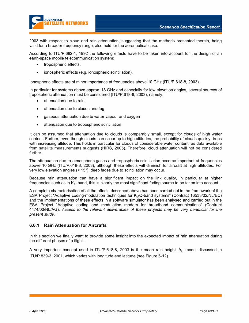
Scenarios Specification Report
6 April 2006 Advantech Satellite Networks Proprietary Page 68/131
2003 with respect to cloud and rain attenuation, suggesting that the methods presented therein, being valid for a broader frequency range, also hold for the aeronautical case.
According to ITU/P.682-1, 1992 the following effects have to be taken into account for the design of an earth-space mobile telecommunication system:
• tropospheric effects,
• ionospheric effects (e.g. ionospheric scintillation),
Ionospheric effects are of minor importance at frequencies above 10 GHz (ITU/P.618-8, 2003).
In particular for systems above approx. 18 GHz and especially for low elevation angles, several sources of tropospheric attenuation must be considered (ITU/P.618-8, 2003), namely:
• attenuation due to rain
• attenuation due to clouds and fog
• gaseous attenuation due to water vapour and oxygen
• attenuation due to tropospheric scintillation
It can be assumed that attenuation due to clouds is comparably small, except for clouds of high water content. Further, even though clouds can occur up to high altitudes, the probability of clouds quickly drops with increasing altitude. This holds in particular for clouds of considerable water content, as data available from satellite measurements suggests (HIRS, 2005). Therefore, cloud attenuation will not be considered further.
The attenuation due to atmospheric gases and tropospheric scintillation become important at frequencies above 10 GHz (ITU/P.618-8, 2003), although these effects will diminish for aircraft at high altitudes. For very low elevation angles (< 15°), deep fades due to scintillation may occur.
Because rain attenuation can have a significant impact on the link quality, in particular at higher frequencies such as in Ka -band, this is clearly the most significant fading source to be taken into account.
A complete characterisation of all the effects described above has been carried out in the framework of the ESA Project “Adaptive coding-modulation techniques for Ka/Q-band systems” (Contract 16533/02/NL/EC) and the implementations of these effects in a software simulator has been analysed and carried out in the ESA Project “Adaptive coding and modulation modem for broadband communications” (Contract 4474/03/NL/AG). Access to the relevant deliverables of these projects may be very beneficial for the present study.
6.6.1 Rain Attenuation for Aircrafts
In this section we finally want to provide some insight into the expected impact of rain attenuation during the different phases of a flight.
A very important concept used in ITU/P.618-8, 2003 is the mean rain height Rh model discussed in ITU/P.839-3, 2001, which varies with longitude and latitude (see Figure 6-12).
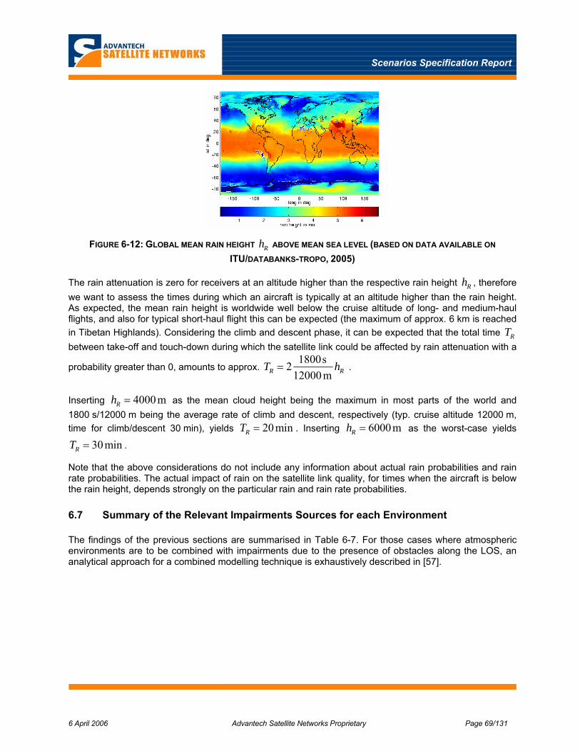
Scenarios Specification Report
6 April 2006 Advantech Satellite Networks Proprietary Page 69/131
FIGURE 6-12: GLOBAL MEAN RAIN HEIGHT Rh ABOVE MEAN SEA LEVEL (BASED ON DATA AVAILABLE ON
ITU/DATABANKS-TROPO, 2005)
The rain attenuation is zero for receivers at an altitude higher than the respective rain height Rh , therefore we want to assess the times during which an aircraft is typically at an altitude higher than the rain height. As expected, the mean rain height is worldwide well below the cruise altitude of long- and medium-haul flights, and also for typical short-haul flight this can be expected (the maximum of approx. 6 km is reached in Tibetan Highlands). Considering the climb and descent phase, it can be expected that the total time RT between take-off and touch-down during which the satellite link could be affected by rain attenuation with a
probability greater than 0, amounts to approx. 1800s2
12000mR RT h= .
Inserting 4000mRh = as the mean cloud height being the maximum in most parts of the world and 1800 s/12000 m being the average rate of climb and descent, respectively (typ. cruise altitude 12000 m, time for climb/descent 30 min), yields 20minRT = . Inserting 6000mRh = as the worst-case yields
30minRT = .
Note that the above considerations do not include any information about actual rain probabilities and rain rate probabilities. The actual impact of rain on the satellite link quality, for times when the aircraft is below the rain height, depends strongly on the particular rain and rain rate probabilities.
6.7 Summary of the Relevant Impairments Sources for each Environment
The findings of the previous sections are summarised in Table 6-7. For those cases where atmospheric environments are to be combined with impairments due to the presence of obstacles along the LOS, an analytical approach for a combined modelling technique is exhaustively described in [57].

Scenarios Specification Report
6 April 2006 Advantech Satellite Networks Proprietary Page 70/131
TABLE 6-7: RELEVANT IMPAIRMENTS SOURCES FOR EACH ENVIRONMENT
Environment Impairments due to Mobility (Obstacles along LOS)
Atmospheric Impairments
Land Vehicular Statistical Fades (Multi State Markov Models at Ku and Ka bands)
Rain Attenuation
Tropospheric Scintillation (esp. at low elevations)
Railway Statistical Fades (Multi State Markov Models at Ku and Ka bands)
Deterministic Fades due to Electrical Trellises
Rain Attenuation
Tropospheric Scintillation (esp. at low elevations)
Aeronautical Single State Ricean Channel (with very high Rice Factor)
Not relevant at cruising altitude
Maritime Single State Ricean Channel (with very high Rice Factor)
Rain Attenuation
Tropospheric Scintillation (esp. at low elevations)

Scenarios Specification Report
6 April 2006 Advantech Satellite Networks Proprietary Page 71/131
7 TRAFFIC MODELS
The following applications were identified as the most attractive for the user in Section 4:
• Web Server or Client
• FTP (or Peer-to-Peer file exchange)
• Video Streaming
• VoIP
• TV
Apart from the TV service (where we can assume an almost constant transmission rate as video encoding quality may be changed in real time to maintain a constant rate on the channel), traffic models for the other applications (which can be used for computer simulations) are given below. Also a model for aggregated LAN traffic is given, as it may be useful for some simulation scenarios where aggregate traffic is generated directly, instead of simulating the individual applications.
7.1 Web Traffic Model
Web traffic model is designed to assist in the evaluation and engineering of shared communications networks. Because the model is behavioural it can be extrapolated to assess the effect of changes in protocols, the network or user behaviour.
According to [41], a web browsing “session” is considered to cover the time in which individual user terminal logs on to a service until the time the user terminal disconnects from the service. The session breaks into separate phases called “packet calls”, separated by idle periods referred as the Reading Time. By definition, a packet call is the sequence of packets exchanged between transmitter and receiver after a single user request (i.e. after the user clicked a hyperlink in the web browsing case). The above definitions are pictorially shown in Figure 7-1.
FIGURE 7-1: SOURCE TRAFFIC MODELLING APPROACH.
The packet calls are composed of a main object (the html file) and zero or more embedded objects (images, java applets, etc…). After the main object is sent, the traffic generator remains idle for the time necessary to parse the main object (Parsing Time), before transmitting the embedded objects. The size of both the main and the embedded objects has a truncated lognormal distribution, the number of embedded

Scenarios Specification Report
6 April 2006 Advantech Satellite Networks Proprietary Page 72/131
objects per request has a truncated Pareto distribution, and the reading and parsing time have an exponential distribution. The full traffic model is described in detail in [41]. It worth noting that, with the aim to adapt this model (which refers to terrestrial communications) to satellite communications, a fixed delay is added to the parsing time to take into account the correct propagation delay.
The parameters proposed by the 3GPP for the server-to-client web-browsing model are shown in Table 7-1. With regard to the client-to-server communications, the same model can be employed, changing the parameters of the main object size and of the embedded object size distributions in order to reflect the characteristics of a “HTTP get” request. The results of an empirical analysis, documented in [42], show that for the client-to-server traffic the minimum packet length is 8 bytes, the maximum one is 2404 bytes and the average one is about 320 bytes. With these parameters it is possible to adapt the above model for simulating also client to server communications.
TABLE 7-1: WEB SERVER MODEL PARAMETERS.
Component Distribution Parameters PDF
Main object size (SM)
Truncated Lognormal
Mean = 10710 bytes Std. dev. = 25032 bytes Minimum = 100 bytes Maximum = 2 Mbytes
( )
35.8,37.1
0,22
ln 2exp
2
1
==
⎥⎥⎦
⎤
⎢⎢⎣
⎡≥
−−=
µσσ
µ
σπx
x
xxf
Embedded object size
(SE)
Truncated Lognormal
Mean = 7758 bytes Std. dev. = 126168
bytes Minimum = 50 bytes Maximum = 2 Mbytes
( )
17.6,36.2
0,22
ln 2exp
2
1
==
⎥⎥⎦
⎤
⎢⎢⎣
⎡≥
−−=
µσσ
µ
σπx
x
xxf
Number of embedded objects per page (Nd)
Truncated Pareto
Mean = 5.64 Max. = 53
55,2,1.1
,
,1
===
==
<≤+=
⎟⎠⎞
⎜⎝⎛
mk
mxm
kf x
mxk
x
kf x
α
α
α
αα
Note: Subtract k from the generated random value to obtain Nd
Reading time (Dpc)
Exponential Mean = 30 sec
033.0
0,
=
≥−
=
λ
λλ xe
xf x
Parsing time (Tp)
Exponential Mean = 0.13 sec
69.7
0,
=
≥−
=
λ
λλ xe
xf x

Scenarios Specification Report
6 April 2006 Advantech Satellite Networks Proprietary Page 73/131
7.2 FTP Traffic Model
FTP traffic is modelled as suggested in [41]. In particular, the FTP session is composed of one or more file downloads (or upload). Between two file downloads (or uploads), the traffic generator remains idle for the Reading Time. The parameters proposed by the 3GPP for the server-to-client FTP model are shown in Table 7-2.
TABLE 7-2: FTP MODEL PARAMETERS.
Component Distribution
Parameters
File size (S) Truncated Lognormal
Mean = 2Mbytes Std. Dev. = 0.722 Mbytes
Maximum = 5 Mbytes ( )
45.14,35.0
0,22
ln 2exp
2
1
==
⎥⎥⎦
⎤
⎢⎢⎣
⎡≥
−−=
µσσ
µ
σπx
x
xxf
Reading time (Dpc)
Exponential Mean = 180 sec.
006.0
0,
=
≥−
=
λ
λλ xe
xf x
7.3 Video Streaming Model
Also for the video streaming service, the model described in [41] has been taken as reference. A video streaming session is defined as the entire video streaming call time and is subdivided into frames. Each frame of video data arrives at a regular interval T determined by the number of frames per second (fps). Each frame is decomposed into a fixed number of slices, each transmitted as a single packet. The size of these packets/slices is distributed as a truncated Pareto distribution. Encoding delay, Dc, at the video encoder introduces delay intervals between the packets of a frame. These intervals are modelled by a truncated Pareto distribution. The video streaming model is depicted in Figure 7-2, whilst the proposed model parameter for a source video rate of 64 kbps are illustrated in Table 7-3.

Scenarios Specification Report
6 April 2006 Advantech Satellite Networks Proprietary Page 74/131
FIGURE 7-2: VIDEO STREAMING MODEL.
TABLE 7-3: VIDEO STREAMING MODEL PARAMETERS.
Information types Inter-arrival time between the beginning of each frame
Number of packets (slices)
in a frame
Packet (slice) size
Inter-arrival time between packets (slices) in a frame
Distribution Deterministic (Based on
10fps)
Deterministic Truncated Pareto
(Mean= 50bytes, Max= 250bytes)
Truncated Pareto (Mean= 6ms, Max=
12.5ms)
Distribution Parameters
100ms 8 K = 40 bytes α = 1.2
K = 2.5ms α = 1.2
7.4 VoIP Model
With regard to VoIP, a typical voice model has been selected. The voice call inter-arrival time is a modelled as a Poisson process. The voice traffic is modelled as an alternating sequence of talk spurt and silences. During each talk spurt, voice packets are generated periodically, and during silent periods, no packets are generated. A Markov chain with two states is used to model the characteristics of VoIP generated traffic (Figure 7-3). This model can be characterised by the voice activity factor, the mean talk spurt duration, the vocoder bit-rate (supposed fixed) and the vocoder frame length.
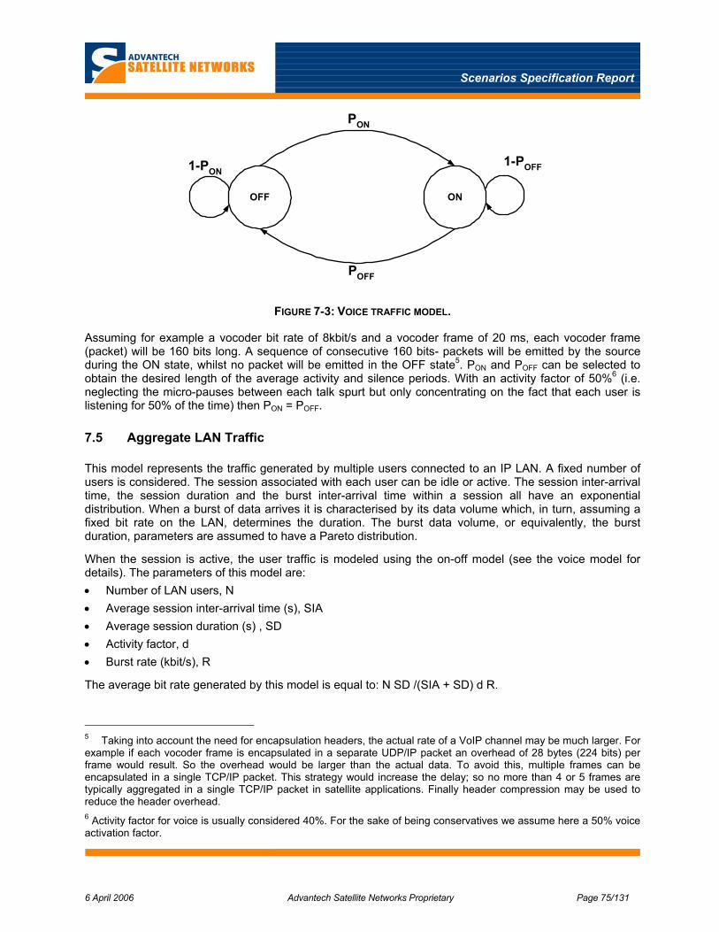
Scenarios Specification Report
6 April 2006 Advantech Satellite Networks Proprietary Page 75/131
OFF ON
PON
POFF
1-POFF1-PON
FIGURE 7-3: VOICE TRAFFIC MODEL.
Assuming for example a vocoder bit rate of 8kbit/s and a vocoder frame of 20 ms, each vocoder frame (packet) will be 160 bits long. A sequence of consecutive 160 bits- packets will be emitted by the source during the ON state, whilst no packet will be emitted in the OFF state5. PON and POFF can be selected to obtain the desired length of the average activity and silence periods. With an activity factor of 50%6 (i.e. neglecting the micro-pauses between each talk spurt but only concentrating on the fact that each user is listening for 50% of the time) then PON = POFF.
7.5 Aggregate LAN Traffic
This model represents the traffic generated by multiple users connected to an IP LAN. A fixed number of users is considered. The session associated with each user can be idle or active. The session inter-arrival time, the session duration and the burst inter-arrival time within a session all have an exponential distribution. When a burst of data arrives it is characterised by its data volume which, in turn, assuming a fixed bit rate on the LAN, determines the duration. The burst data volume, or equivalently, the burst duration, parameters are assumed to have a Pareto distribution.
When the session is active, the user traffic is modeled using the on-off model (see the voice model for details). The parameters of this model are: • Number of LAN users, N • Average session inter-arrival time (s), SIA • Average session duration (s) , SD • Activity factor, d • Burst rate (kbit/s), R
The average bit rate generated by this model is equal to: N SD /(SIA + SD) d R.
5 Taking into account the need for encapsulation headers, the actual rate of a VoIP channel may be much larger. For example if each vocoder frame is encapsulated in a separate UDP/IP packet an overhead of 28 bytes (224 bits) per frame would result. So the overhead would be larger than the actual data. To avoid this, multiple frames can be encapsulated in a single TCP/IP packet. This strategy would increase the delay; so no more than 4 or 5 frames are typically aggregated in a single TCP/IP packet in satellite applications. Finally header compression may be used to reduce the header overhead. 6 Activity factor for voice is usually considered 40%. For the sake of being conservatives we assume here a 50% voice activation factor.

Scenarios Specification Report
6 April 2006 Advantech Satellite Networks Proprietary Page 76/131
8 SATELLITE SYSTEM CHARACTERISTICS
The satellite systems for broadband mobility use transparent satellites either in the Ku or Ka band. Since the MSS frequency allocations are in the FSS bands, it is expected that these will be the same satellites used by the fixed satellite service. Further, the initial rollout of a commercial broadband mobile system will very likely use capacity on existing in-orbit Ku band systems.
Future systems will undoubtedly utilise the Ka band MSS frequency allocations, especially where these have a Primary status. In general, in-orbit Ka band space segment is somewhat limited, although this will change in the near future with the launch of a number of new commercial systems. It will be interesting to see if this will spur the construction and deployment of broadband mobile systems in Ka band.
The subsections below identify and describe candidate network scenarios for mobility satellite system scenarios and the associated space segment performance for subsequent link budget analysis in WP 1.2.
8.1 System Architecture Scenarios
The system architecture scenarios for broadband MSS reflect the range of operation of the different mobile applications as well as the beam coverage of existing satellite system architectures. In general, a given satellite system will have either a single or a multi-beam coverage. The system architecture scenarios are listed in Table 8-1 and described in the subsections below.
Mobile systems inherently span a coverage area depending on its range of operation. For aeronautical mobile, the range of operation can be limited to a regional service for domestic air travel or extend to a global service for trans-continental travel. Similarly, maritime mobility can have regional as well as a global range of operation. Global service in general also means trans-oceanic coverage which has important implications for satellite coverage as discussed below. Typically, land mobile will be limited to a regional service with continental satellite coverage.
As revealed by the review of existing or proposed commercial broadband mobile systems in Section 3, there is a possible additional scenario based on the use of BSS satellites for the forward path instead of FSS satellites. The former is the more general architecture for bi-directional broadband operation in Ku band as intended by the ITU frequency allocations and recommendations; however the latter approach is an interesting alternative that may turn out to have significant advantages for some applications.
TABLE 8-1: MOBILITY SYSTEM ARCHITECTURE SCENARIOS
Frequency Band FWD/RTN Air Interface
Coverage Application/ Mobile Environment
FSS Scenarios 1. Ku DVB-S2 / RCS Regional- Mono (area)
beam 2. Ka DVB-S2/ RCS Regional – Multi (spot)
beam
Terrestrial Maritime Aeronautical
3. Ku DVB-S2/RCS Global – Multi-satellite, Multi-beam
Aeronautical Maritime
4. Ku DVB-S2/ Satmode Regional – Monobeam 5. Ka DVB-S2/ Satmode Regional- Multibeam
Terrestrial
BSS Scenarios 6. Ku FWD and L band RTN
DVB-S2 / RCS and Satmode
Regional – Mono/Multibeam
Aeronautical Maritime Terrestrial
7. Ku FWD, terrestrial RTN
DVB-S2 / WLAN Regional – Mono/Multibeam
Terrestrial

Scenarios Specification Report
6 April 2006 Advantech Satellite Networks Proprietary Page 77/131
8.1.1 FSS Scenarios
A typical network architecture for one FSS satellite is illustrated in Figure 8-1 below. In this figure, the beams and matching forward and return links are color coded. In general, a satellite based broadband mobile system architecture consists of a network of mobile terminals interconnected to a gateway /Hub by a transparent satellite using DVB-RCS/ DVB-S(2) or SatMode return and forward links. The mobile will traverse the coverage area beams that are in general served by a multiple of gateways and satellites. The gateways are backhauled to terrestrial network access points and to Network Control and Network operations facilities by either a terrestrial ground network or other satellite networks.
G atew ay
T ransparen t sate llite
A ircraftA ircraft
Sh ip T rain
D V B -R C S or Satm ode
R etu rn lin k
T errestria l N etw ork
N O C N C C s
G atew ay
D V B -S2 F orw ard lin k
FIGURE 8-1: SATELLITE BROADBAND MOBILE SYSTEM ARCHITECTURE – FSS TYPE
The FSS system architecture scenarios are rationalised from those originally proposed to five regional scenarios and one global scenario, as identified in Table 8-1. The regional scenarios involve coverage, frequency band and return interface alternatives, whereas there is really only one global option using a Ku band multi-satellite multi-beam architecture.
8.1.1.1 Regional
The regional scenario represents a continental coverage with either single (mono) broadcast type beam or a number of spot beams. A single beam scenario is distinguished from a multi-beam scenario, due to the satellite performance but also whether or not beam handover is required. The better multi-beam satellite performance will permit reduced terminal EIRP but require the beam handover capability.
Typically regional Ku band coverage is single beam while the multi-beam coverage is achieved at Ka band. Examples of these coverages are shown in Figure 8-2 and Figure 8-3 below, for representative North American systems.
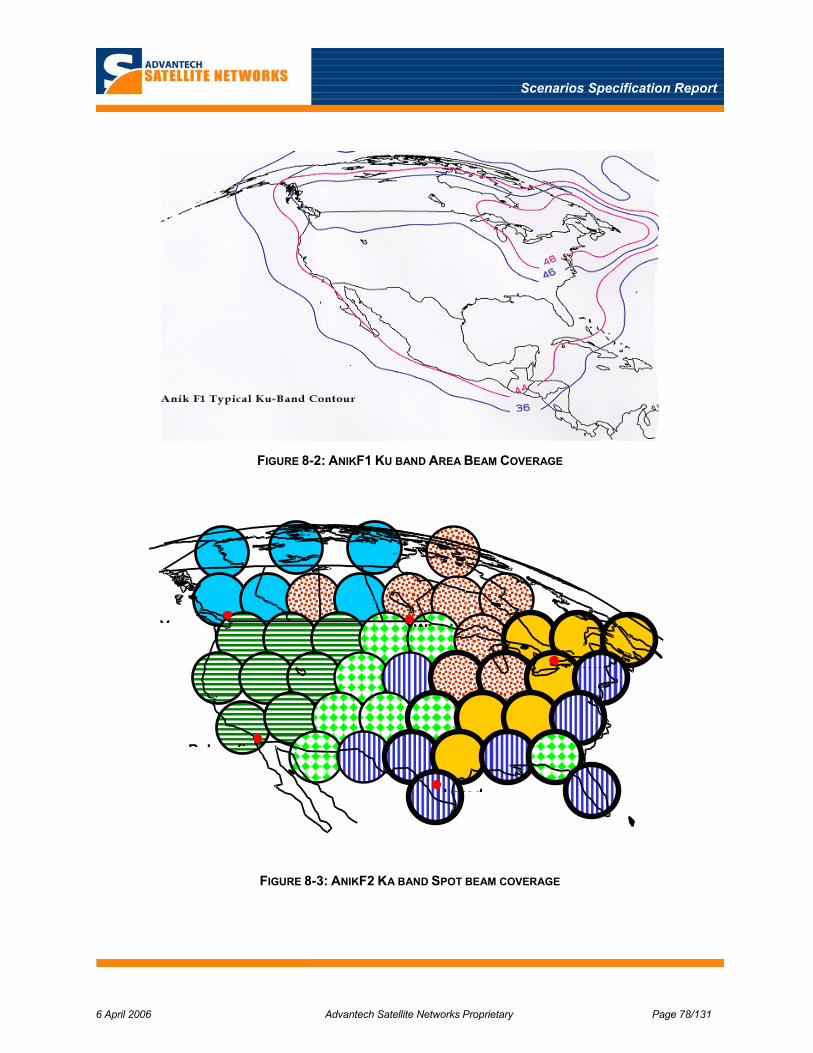
Scenarios Specification Report
6 April 2006 Advantech Satellite Networks Proprietary Page 78/131
FIGURE 8-2: ANIKF1 KU BAND AREA BEAM COVERAGE
FIGURE 8-3: ANIKF2 KA BAND SPOT BEAM COVERAGE
Winnip
Lared
Vancou
Bakersfi
Toront

Scenarios Specification Report
6 April 2006 Advantech Satellite Networks Proprietary Page 79/131
8.1.1.2 Global
The one global scenario represents a general multi-satellite and multi-beam coverage over spanning multiple continents as well as oceans. Such coverage is readily achieved at lower frequency bands (L band) and increasingly at Ku band with selected area beams such as the Telstar 14 NOAR beam as shown in Figure 8-4, providing coverage over the key North Atlantic air traffic route.
FIGURE 8-4: TELSTAR 14 (ESTRELA DO SUL) COVERAGE IN KU-BAND
A truly global coverage will in general be a complex patch work of individual coverage from multiple satellites, likely similar to that conceived and planned for the Boeing Connexion system [2] as shown in Figure 8-5. As described in this reference, for the planned CBB coverage, additional satellite coverage at Ku band will be needed to fill in gaps over the oceans not normally covered by existing Ku coverage. For example, Connexion will use capacity on the Worldsat3 satellite to provide Pacific Ocean coverage.
FIGURE 8-5: CONNEXION BY BOEING PLANNED COVERAGE FOR FULL NETWORK EXPANSION [2]
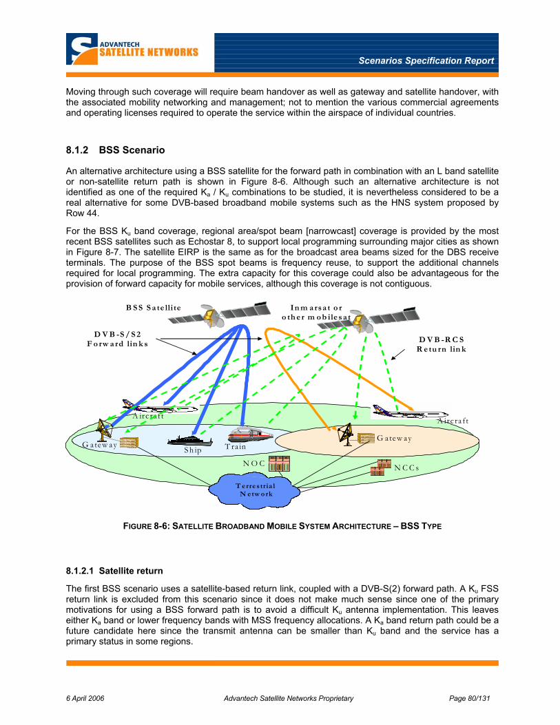
Scenarios Specification Report
6 April 2006 Advantech Satellite Networks Proprietary Page 80/131
Moving through such coverage will require beam handover as well as gateway and satellite handover, with the associated mobility networking and management; not to mention the various commercial agreements and operating licenses required to operate the service within the airspace of individual countries.
8.1.2 BSS Scenario
An alternative architecture using a BSS satellite for the forward path in combination with an L band satellite or non-satellite return path is shown in Figure 8-6. Although such an alternative architecture is not identified as one of the required Ka / Ku combinations to be studied, it is nevertheless considered to be a real alternative for some DVB-based broadband mobile systems such as the HNS system proposed by Row 44.
For the BSS Ku band coverage, regional area/spot beam [narrowcast] coverage is provided by the most recent BSS satellites such as Echostar 8, to support local programming surrounding major cities as shown in Figure 8-7. The satellite EIRP is the same as for the broadcast area beams sized for the DBS receive terminals. The purpose of the BSS spot beams is frequency reuse, to support the additional channels required for local programming. The extra capacity for this coverage could also be advantageous for the provision of forward capacity for mobile services, although this coverage is not contiguous.
G atew ay
A irc ra ftA irc raft
S h ip T ra in
D V B -R C S R e tu rn lin k
T e rre s tria l N e tw o rk
N O C N C C s
G atew ay
D V B -S / S 2 F o rw a rd lin k s
B S S S a te llite In m a rsa t o r o th e r m o b ile sa t
FIGURE 8-6: SATELLITE BROADBAND MOBILE SYSTEM ARCHITECTURE – BSS TYPE
8.1.2.1 Satellite return
The first BSS scenario uses a satellite-based return link, coupled with a DVB-S(2) forward path. A Ku FSS return link is excluded from this scenario since it does not make much sense since one of the primary motivations for using a BSS forward path is to avoid a difficult Ku antenna implementation. This leaves either Ka band or lower frequency bands with MSS frequency allocations. A Ka band return path could be a future candidate here since the transmit antenna can be smaller than Ku band and the service has a primary status in some regions.
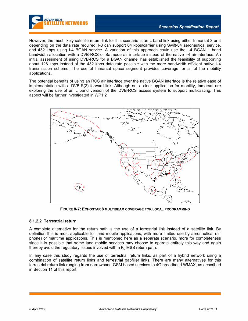
Scenarios Specification Report
6 April 2006 Advantech Satellite Networks Proprietary Page 81/131
However, the most likely satellite return link for this scenario is an L band link using either Inmarsat 3 or 4 depending on the data rate required; I-3 can support 64 kbps/carrier using Swift-64 aeronautical service, and 432 kbps using I-4 BGAN service. A variation of this approach could use the I-4 BGAN L band bandwidth allocation with a DVB-RCS or Satmode air interface instead of the native I-4 air interface. An initial assessment of using DVB-RCS for a BGAN channel has established the feasibility of supporting about 128 kbps instead of the 432 kbps data rate possible with the more bandwidth efficient native I-4 transmission scheme. The use of Inmarsat space segment provides coverage for all of the mobility applications.
The potential benefits of using an RCS air interface over the native BGAN interface is the relative ease of implementation with a DVB-S(2) forward link. Although not a clear application for mobility, Inmarsat are exploring the use of an L band version of the DVB-RCS access system to support multicasting. This aspect will be further investigated in WP1.2
FIGURE 8-7: ECHOSTAR 8 MULTIBEAM COVERAGE FOR LOCAL PROGRAMMING
8.1.2.2 Terrestrial return
A complete alternative for the return path is the use of a terrestrial link instead of a satellite link. By definition this is most applicable for land mobile applications, with more limited use by aeronautical (air phone) or maritime applications. This is mentioned here as a separate scenario, more for completeness since it is possible that some land mobile services may choose to operate entirely this way and again thereby avoid the regulatory issues involved with a Ku MSS return path.
In any case this study regards the use of terrestrial return links, as part of a hybrid network using a combination of satellite return links and terrestrial gapfiller links. There are many alternatives for this terrestrial return link ranging from narrowband GSM based services to 4G broadband WMAX, as described in Section 11 of this report.

Scenarios Specification Report
6 April 2006 Advantech Satellite Networks Proprietary Page 82/131
8.2 Space Segment
The space segment for the above system architectures include: 1) Ku / Ka FSS satellites with forward and return path transponders for the FSS scenarios, and 2) BSS satellite with Ku forward transponders combined with L band mobile satellites such as Inmarsat 4 spot beams for the return path. As reviewed above, a BSS scenario using a terrestrial return link is also identified.
The FSS space segment includes one or several satellites with performances equivalent to those used for existing Ku -band or Ka -band FSS services. Three general types of satellite coverage are defined for the system architecture scenarios: 1) a Ku band area beam for the regional coverage , 2) Ka band spot beams for the regional coverage 2) a multiple area beams for the global (continental and oceanic).
The satellite performance for the mobile scenarios will critically depend on the beam size of the type of coverage and the location of a mobile within that coverage. Typically, satellite performance is specified at edge of coverage defined at the contour of the coverage area for which the EIRP and G/T are a number of dBs down from the peak of the beam performance. Typically 10 dB down represents the worst case or low performance case for 100 % coverage. Due to the large areas involved with Ku band area beams and even more so for global coverage, it is useful to consider a reduced coverage area such as 90 % with about typically 4 dB better performance, depending on the beam size.
Accordingly, the baseline satellite performance of the coverage types is selected based on a somewhat arbitrary assumption of what beam sizes constitutes regional area, spot and a global area beams. In general Ku area beams corresponds to semi-continental areas of about 2 x 8 degrees, spot beams are about 1 degree, and the global area beams are assumed to be 4 x 8 degrees.
The baseline performance for satellite [saturated] EIRP and G/T for each of the scenarios are given in Table 8-2 below, referenced to a 36 MHz transponder.
TABLE 8-2: SATELLITE AND TERMINAL BASELINE PERFORMANCE
Beam size Satellite performance Scenarios degrees EIRP (dBW) G/T (dB/K)
FSS Scenarios 1. Ku –Regional mono beam 2 x 8 48 1 2. Ka – Regional multi beam 1 55 15 3. Ku –Global multi beam 4 x 8 44 -2 4. Ku –Regional Satmode 2 x 8 48 1 5. Ka –Regional Satmode 1 55 15 BSS Scenarios 6. Ku FWD and L band RTN 4 x 8 50 ~15 (I-4) 7. Ku FWD, terrestrial RTN 4 x 8 50 NA
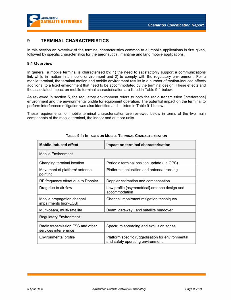
Scenarios Specification Report
6 April 2006 Advantech Satellite Networks Proprietary Page 83/131
9 TERMINAL CHARACTERISTICS
In this section an overview of the terminal characteristics common to all mobile applications is first given, followed by specific characteristics for the aeronautical, maritime and land mobile applications.
9.1 Overview
In general, a mobile terminal is characterised by: 1) the need to satisfactorily support a communications link while in motion in a mobile environment and 2) to comply with the regulatory environment. For a mobile terminal, the terminal motion and mobile environment results in a number of motion-induced effects additional to a fixed environment that need to be accommodated by the terminal design. These effects and the associated impact on mobile terminal characterisation are listed in Table 9-1 below.
As reviewed in section 5, the regulatory environment refers to both the radio transmission [interference] environment and the environmental profile for equipment operation. The potential impact on the terminal to perform interference mitigation was also identified and is listed in Table 9-1 below.
These requirements for mobile terminal characterisation are reviewed below in terms of the two main components of the mobile terminal, the indoor and outdoor units.
TABLE 9-1: IMPACTS ON MOBILE TERMINAL CHARACTERISATION
Mobile-induced effect Impact on terminal characterisation
Mobile Environment
Changing terminal location Periodic terminal position update (i.e GPS)
Movement of platform/ antenna pointing
Platform stabilisation and antenna tracking
RF frequency offset due to Doppler Doppler estimation and compensation
Drag due to air flow Low profile [asymmetrical] antenna design and accommodation
Mobile propagation channel impairments [non-LOS]
Channel impairment mitigation techniques
Multi-beam, multi-satellite Beam, gateway , and satellite handover
Regulatory Environment
Radio transmission FSS and other services interference
Spectrum spreading and exclusion zones
Environmental profile Platform specific ruggedisation for environmental and safety operating environment

Scenarios Specification Report
6 April 2006 Advantech Satellite Networks Proprietary Page 84/131
9.1.1 Indoor Unit
The overall architecture of indoor units for the mobile applications will be generally similar to that of indoor units for non-mobile applications, aside from any ruggedisation or customisation needed for the environmental profile of the mobile platform. However, the indoor units will need a number of new mobility related functions that are expected to include the following:
• De-spreading of the forward link signal and spreading of the return link signal.
• Management of mobility-related information, including for example data bases of: system coverage beams, carriers, and exclusions zones of terrestrial earth stations in the FS, SRS, and RAS services.
• Acceptance and generation of mobility-specific signalling.
• Execution of the mobility-related functions, including at least some elements of the detection of conditions in which handovers are desired.
• Special functions needed for synchronisation acquisition and maintenance in the mobile environment, including Doppler compensation and special functions for maintenance during handovers.
• Execution of algorithms that prevent transmissions in situations where these could cause interference to other services that must be protected, as defined by the exclusion zones database.
Based on initial results of previous studies [1] the required spectral spreading represents a modest add-on of spreading and de-spreading functions to the current DVB-RCS return and DVB-S forward path transmission schemes.
9.1.2 Outdoor Unit
In general, the outdoor unit (ODU) of all mobile terminals will consist of an antenna, either electronically or mechanically steered to track the satellite, connected to the ODU transceiver electronics (LNB, HPA) and antenna control unit. Of the number of known commercial mobile ODUs that are used for existing proprietary broadband mobile systems, mechanically steered antennas appear to be universally adopted.
There are two broad types of possible ODU configurations depending on the mobile application. The first type of mobile uses “VSAT type” antennas for maritime as well as some land mobile applications, which are mounted on a stabilised platform and interconnected in a standard way to an indoor unit. For a second type of mobile, smaller low profile antennas for aircraft and high speed trains are required to minimise air drag. For this type of terminal, an alternative ODU configuration is potentially required to minimise the heat build-up in the antenna radome. This ODU configuration will typically consist of a mechanically steered antenna enclosed in a radome and with an RF connection to an “indoor” antenna control unit and HPA
9.1.2.1 Antenna Subsystem
As introduced above, there are two broad types of antenna systems for mobile terminals: large VSAT sized antennas and typically smaller low profile antennas. The first type is suitable for slow moving terminals where accommodation and wind resistance are not issues. This is similar to a fixed terminal configuration with the outdoor unit mounted on the mechanically steered antenna assembly itself and additionally enclosed in a radome to reduce wind resistance. In this case the inter-facility link to the indoor unit would be at an IF frequency such as L band. This approach is generally suitable for slower moving mobile platforms permitting larger antenna apertures with a larger radome volume and lower transit powers.
For high speed platforms, high velocity and wind resistance becomes an issue both with respect to antenna size, stability and vehicle fuel efficiency. Antennas of smaller circular or low profile asymmetrical aperture are needed to accommodate terminals in confined spaces or on smaller platforms. Depending on where the antenna can be accommodated, this may dictate an asymmetrical antenna with a low profile in

Scenarios Specification Report
6 April 2006 Advantech Satellite Networks Proprietary Page 85/131
the elevation axis enclosed in a radome. A smaller effective aperture size also serves to alleviate the required tracking and stabilisation accuracy. Further, it is observed that the antenna patterns of these asymmetrical types of antennas and of small antennas, do not meet the FSS ITU sidelobe envelope requirement in ITU-R 465-5 [14] achieved by VSAT sized circular apertures.
The pointing and stabilisation of the mobile antenna platform are essential to 1) minimise the loss due to misalignment of the antenna main lobe to the wanted satellite and 2) prevent excessive off-axis EIRP emission in the direction of adjacent satellites. Typically, the criteria for pointing accuracy are such as to limit the maximum mis-pointing degradation to about 1 dB or less, depending on the antenna beamwidth. There are a number of stabilised and tracking antenna systems used in commercial mobile broadband products and systems at Ku and Ka band, as reviewed in section 3.
9.1.2.2 RF Subsystem
As introduced above, there are two possible RF configurations of a mobile terminal, depending on the type of mobile platform. The first is similar to a fixed RCST with the outdoor unit mounted on the mechanically steered antenna assembly itself and additionally enclosed in a radome to reduce wind resistance. In this case the inter-facility link to the indoor unit would be at an IF frequency such as L band. This approach is suitable for mobile platforms, permitting larger antenna apertures with a larger radome volume and lower transmit powers.
For fast moving mobile platforms such as aircraft, which require a low profile antenna system enclosed in a radome, the issue of heat dissipation and resulting heat build-up in the radome becomes a key issue, particularly due to the relatively high transmit power levels required depending on the data rate supported. For this type of terminal, the HPA is located externally from the radome as illustrated by the block diagram of a second possible ODU configuration shown in Figure 9-1 below. This configuration typically consists of a mechanically steered antenna enclosed in a radome and with an RF connection through a rotary joint to an “indoor” antenna control unit and HPA.
This question of mobile transmitter heat dissipation is a critical item to be investigated in WP 1.2.2., however to minimise the power dissipation problem for mobiles with low profile and/or smaller antennas, it is expected that TWTA-like devices, referred to a microwave power modules (MPM) are recommended for the HPA instead of SSPAs, since the former are more efficient in DC power consumption; typically 25-30 % versus 10 % for SSPAs.

Scenarios Specification Report
6 April 2006 Advantech Satellite Networks Proprietary Page 86/131
TX/RX Feed
LNA
Upconvertor(L-Ku)
Downconvertor(Ku-L)
MPM (Microwave
power Module)
Low profile /small antenna aperture
DVB-S/S2 Receiver
RCS MF-TDMA Modulator
DVB-RCS Indoor Unit
Antenna Az/Elev Positioner
Antenna Conrol Unit
(ACU)Power Supply
Rotary Joint
FIGURE 9-1: MOBILE TERMINAL RF CONFIGURATION FOR LOW PROFILE ANTENNA
The Antenna Control Unit (ACU) monitors the received signal and controls the antenna azimuth/elevation positioner. Depending on the method of antenna control, the ACU in general includes: a GPS receiver and/or interface to platform navigational data, inertial reference, rate sensors and beam steering unit. The antenna positioner performs 2-axis antenna scanning in azimuth and elevation, such as step track or conical scanning.
9.2 Aeronautical
Typically, an aeronautical broadband application is characterised as a highly mobile high velocity platform with a line of sight propagation channel and complex regulatory environment. Highly mobile refers to the wide area of operation ranging from regional to global coverage. While regional systems can be limited to a single beam and satellite, a global aeronautical broadband service necessarily involves multiple beams and satellites.
The terminal for the aeronautical application will certainly require the type 2 ODU configuration with a low profile asymmetrical or small circular antenna and HPA separated from the antenna to minimise heat build-up in the radome.
Based on target requirements in an RFI from Airbus for the Broadway aeronautical broadband system, on evidence of the other commercial aeronautical broadband systems reviewed in section 3, and satellite performance, terminals for two broad aeronautical scenarios can be identified:
• Global scenario: low profile asymmetrical antenna with an effective circular aperture of about 60 cm
• Regional scenario: circular aperture of about 30cm
Depending on the specific architecture scenario, and satellite orbit spacing, terminals with these smaller effective aperture sizes will likely require some amount of spectral spreading to limit off-axis EIRP into FSS. In addition, the interference scenarios identified above for the fixed terrestrial and scientific services will require the control and monitoring of terminal location with respect to an internal database of exclusion zones, such that the terminal stops transmission or changes frequency of operation to prevent interference.

Scenarios Specification Report
6 April 2006 Advantech Satellite Networks Proprietary Page 87/131
For a global aeronautical service, the terminal needs to support soft beam handover and associated mobility management and networking. Soft beam handover will require that the terminal not log-off when the forward and return carriers are switched from those in the old to those in the new beam. To achieve this, the terminals will require a modified NCR recovery mechanism to free-wheel during the switchover period. In addition the terminal will need to support forward and return signalling associated with the handover process.
9.3 Maritime
In general for maritime applications the slow to moderate speeds of the vessels and generally more space, permits the use of larger VSAT type parabolic apertures mounted on a stabilised platform, depending on the size of the ship. These antennas are typically enclosed in a spherical shaped radome to protect it from the elements. Maritime VSAT terminals are already in commercial use as reviewed in section 3.
This VSAT type of terminal configuration may be similar for smaller vessels and pleasure craft, unless space is a factor which may necessitate a more compact ODU that would in turn require the alternative ODU similar to that described above for aeronautical mobile.
According to the specific regulatory environment for maritime mobile service (Resolution 902), a minimum antenna size of 1.2 m is recommended; however, this could be reduced to 0.6 m subject to coordination. The equivalent of global and regional scenarios can be envisioned for these aperture sizes corresponding to cruise ships and ferries.
9.4 Land
Terminals for land mobile applications potentially represent a wide range of versions ranging from small vehicles to high speed trains. Slower moving vehicles could potentially have VSAT type terminals, while the faster moving trains will have terminals similar to that for aeronautical applications.
In particular, for land mobile the constraints imposed by the harsh propagation conditions, impose a number of functional requirements that go beyond those required in the more benign propagation environments experienced in aeronautical, maritime and some limited land mobile applications. It is expected that the additional features in the land mobile terminal will include some or all of the following:
• Countermeasures for short-duration link interruptions, such as deep interleaving, higher-layer FEC and random-access techniques for the return link.
• Countermeasures for long-duration link interruptions, such as additional air interfaces for transmission though terrestrial gap fillers.
Of these, the additional modem(s) needed for the terrestrial gap fillers will represent significant new hardware developments. The remaining features can likely be implemented in software and/or firmware.
Three different approaches to commercial land mobile antenna system aperture design have been observed depending on the type of vehicle; mass transit vehicles such as train and buses, and other smaller vehicles including RVs, jeeps, and trucks.
For smaller vehicular mobiles with slow to moderate speed, VSAT type reflector antennas (1m + ) have been mounted on the rear or roof of trucks or on top of trains. In all cases, the antennas are enclosed in a large hemispherical radome.
However, it is expected that the mobile high speed train systems will migrate to a low profile antenna, to minimise wind resistance and avoid any clearance hazard, using mechanically steered asymmetrical reflector antennas enclosed in low profile radomes. For large passenger vehicles such as RVs and jeeps, it is expected that bidirectional antennas will employ mechanically steered set of microstrip array antennas similar to the Raysat Eagleray product, although this is not believed to be in commercial use yet.
Scenarios Specification Report
6 April 2006 Advantech Satellite Networks Proprietary Page 88/131
10 TERRESTRIAL WIRELESS NETWORKS
The evolution of wireless communications networks in general is in the direction of higher bandwidths, higher data rates and greater mobility. This is being driven by two main factors: The on-going expansion of cellular networks and more ubiquitous IP connectivity in terms of both applications and network coverage, and the increased distribution of entertainment content.
The first factor is the evolution of the telecom world in supporting wireless networks that are increasingly moving to support both higher rate and IP based applications, while the latter is the evolution of the broadcast world in supporting multicasting to small handheld devices, IP-TV, and DVB based interactivity — including DVB-RCS. An increasing overlap of these two worlds can be seen in the example of IP-TV, which utilises MPEG-4 over IP with significantly improved video compression (and hence bandwidth efficiency), and improved support for interactivity and authoring of content. As such, a convergence of these two classically opposing networking technologies, broadcasting versus point–to-point, is underway as part of the wireless evolution. Another convergence of circuit switched (voice) and packet switched (data) is also taking place in the telecom world itself. This overall convergence is sometimes referred to as the “Triple Play”, where video on demand (VOD, IPTV), Voice over IP (VoIP) and wireless ADSL (broadband IP) are supported to one mobile terminal.
The rollout of the predominantly terrestrial component of these broadband mobile networks is particularly relevant to potential satellite based networks for land mobile applications. There are two aspects to this; first, the terrestrial networks are competing with satellite-based solutions. Secondly, terrestrial technologies can be complementary to satellite in a hybrid wireless network. This impact is somewhat less relevant for aeronautical applications and perhaps of intermediate impact to maritime services, depending on the maritime applications and type of vessel.
From the competitive standpoint, the terrestrial mobile broadband networks may be more cost competitive than satellite and/or enable an improved level of service. While satellite does have the natural advantage of wide area coverage, the terrestrial cellular networks have historically dominated and been more successful in voice based cellular communications, as evidenced by the commercial difficulties experienced by the Iridium and Globalstar LEO satellite networks. GEO satellite networks have achieved better success (Thuraya, AceS), but primarily where there are obstacles to developing terrestrial cellular infrastructure.
From a hybrid networking standpoint, a terrestrial network may serve efficiently to extend and fill gaps in the satellite coverage, such as in tunnels or other locations without a clear view of the satellite. In such an arrangement, an existing 3-4 G terrestrial network enhances the coverage of the satellite network by trans-coding or terminating the satellite link completely at the Gapfiller station. This approach is complementary to the use of gap-filler stations that are an integral part of the satellite network.
This section provides a summary of the status and trends in terrestrial wireless networks and presents an assessment of the impact on the choices of scenarios that should be targetted by satellite-based services. Section 11 provides a comprehensive assessment of gapfiller technologies, including those currently being considered by the DVB consortium.
10.1 Overview of Terrestrial Technologies
As introduced above, the evolution of wireless (cellular) terrestrial networks is proceeding on two main fronts: The progression from both narrowband circuit-switched to broadband packet-switched services, and the convergence of point-to-point (unicast) and broadcast applications.
In general, wireless networks support a fixed connection to a nomadic (portable) terminal and a mobile connection to a moving terminal. While the slower speed 2G circuit switched wireless networks support both nomadic and moving terminals, the higher speed broadband packet-switched (IP) wireless networks initially support nomadic terminals and with recent enhancements also support mobility. The move from 2G
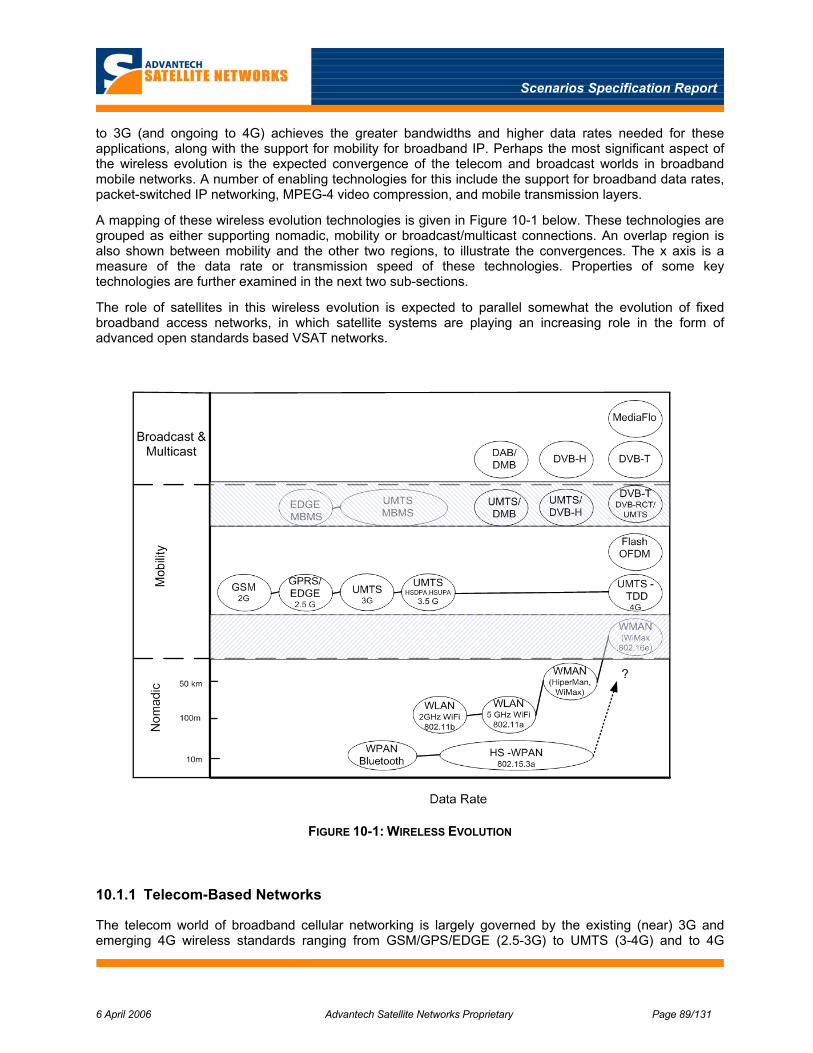
Scenarios Specification Report
6 April 2006 Advantech Satellite Networks Proprietary Page 89/131
to 3G (and ongoing to 4G) achieves the greater bandwidths and higher data rates needed for these applications, along with the support for mobility for broadband IP. Perhaps the most significant aspect of the wireless evolution is the expected convergence of the telecom and broadcast worlds in broadband mobile networks. A number of enabling technologies for this include the support for broadband data rates, packet-switched IP networking, MPEG-4 video compression, and mobile transmission layers.
A mapping of these wireless evolution technologies is given in Figure 10-1 below. These technologies are grouped as either supporting nomadic, mobility or broadcast/multicast connections. An overlap region is also shown between mobility and the other two regions, to illustrate the convergences. The x axis is a measure of the data rate or transmission speed of these technologies. Properties of some key technologies are further examined in the next two sub-sections.
The role of satellites in this wireless evolution is expected to parallel somewhat the evolution of fixed broadband access networks, in which satellite systems are playing an increasing role in the form of advanced open standards based VSAT networks.
FIGURE 10-1: WIRELESS EVOLUTION
10.1.1 Telecom-Based Networks
The telecom world of broadband cellular networking is largely governed by the existing (near) 3G and emerging 4G wireless standards ranging from GSM/GPS/EDGE (2.5-3G) to UMTS (3-4G) and to 4G

Scenarios Specification Report
6 April 2006 Advantech Satellite Networks Proprietary Page 90/131
WMAN (WiMAX, HiperMAN). These are shown as the Nomadic and Mobility technologies in Figure 10-1, including the return channel component of the technologies in the overlap regions.
Within the telecom world itself, there has historically been a distinction between the voice based (circuit switched) cellular networks and purely data based (packet switched) IP networks. The former have been governed by wireless standards bodies including TIA and ETSI, while the latter have been governed by wireline and wireless computer (IP) networking standards created by IEEE, ETSI and IETF. With the emergence of voice over IP, the increasing universality of IP data applications, and smaller portable and handheld computers merging into cellular devices, there is also a convergence of these two telecom technologies in advanced UMTS and in particular in the form of WMAN (WiMax or HiperMAN) .
The following sub-sections presents the situation and outlook for the most promising telecom-based technologies. The choice is admittedly somewhat subjective, and the treatment is far from comprehensive. The examples have been chosen to illustrate the capabilities that are or will shortly be available in terrestrial networks.
10.1.1.1 WiMAX
WiMAX is a transmission technology sponsored by the IEEE, originally intended for fixed wireless access, mainly for IP networks. At the physical layer, it primarily uses OFDM(A). The MAC layer uses demand-assigned resource management, with provisions for support of different QoS classes (real time, best-effort, etc.). Unlike WiFi, WiMAX is targetted to licensed operation.
The most recent version of the WiMAX standard (IEEE 802.16e-2005 [1]) exploits the robustness inherent in the OFDM technique to add support for mobility. It is designed to operate with bandwidths up to 20 MHz. This is a very flexible standard, both at the air interface level [25] and in terms of its ability to operate with a number of different backbone networks [26]. WiMAX itself is largely a physical and MAC-layer standard. With this flexibility, we judge that WiMAX has very significant potential to become an industry workhorse. Deployments have already begun for nomadic and fixed applications; there are even deployments of (pre-standard) mobile WiMAX applications; for example Wi-LAN’s “Libra Mobilis” [27].
Potential obstacles to the deployment of WiMAX include competition from UMTS-based solutions (see below). Also, in Europe at least, deployment is potentially hampered by the fact that there are few frequency bands available across the continent. This necessitates different implementations for different countries. It is even alleged that spectrum allocations to this type of service are being deliberately limited in some jurisdictions, in order to favour deployment of UMTS-based solutions.
There are two characteristics of WiMAX that are of potential importance for its ability to present powerful competition to satellite-based networks. The design parameters of the 802.16e air interface have been chosen with focus on terminal velocities only up to 120 km/hr. This limitation excludes high-speed trains, a potentially large section of the market; at least in Europe. The terminal velocity affects channel characteristics such as Doppler shift and coherence bandwidth. We have not investigated the matter in detail; however, we anticipate that a judicious selection of air interface parameters such as carrier bandwidth, in combination with active Doppler compensation, could serve to overcome this. This may however be a moot point, as discussed below.
The other potentially important characteristic is that the range covered by a WiMAX base station (i.e., the cell radius) is limited to a few km. This property means that the infrastructure network needs to be fairly dense. This will likely limit the rate of deployment in rural areas.
Nevertheless, due to its many powerful characteristics, we anticipate that WiMAX will see significant deployment in the coming years, at least in urban areas where the customer base will exist. Where deployed, such networks will provide a powerful and likely cost-effective alternative to satellite based solutions. We note that in urban areas, where this is likely to happen first, “high-speed” trains typically do not actually go at very high speed; thereby easing the potential problems outlined above.

Scenarios Specification Report
6 April 2006 Advantech Satellite Networks Proprietary Page 91/131
10.1.1.2 UMTS
UMTS was originally conceived as an all-inclusive technology for mobile communications, covering everything from domestic cordless phones to cellular, wireless local area networks and satellite phones. Initial commercial deployments have been taking place in the last few years. However, these are rather more modest in scope; they are essentially limited to being an evolution of second-generation systems such as GSM. UMTS (3G) networks use a broadband CDMA air interface that can offer higher data rates than GSM (up to 384 kb/s for mobile terminals), as well as somewhat more sophisticated packet data services. However, the fundamental nature of UMTS remains that of a mobile telephony network. Even recent initiatives to provide for example IP telephony over GSM and UMTS network typically use the native voice services in the mobile network and convert to VoIP only in the fixed network.
There is a very real threat that UMTS could be overtaken by high-performance competition from the wireless computer network arena — WiMAX in particular. This threat is not only for packet data services, but also for telephony, the traditional domain of the GSM/UMTS networks. VoIP-based wireless handsets for WIFI and WiMAX networks are starting to appear (e.g, the Samsung M8000). This threat has caused the UMTS community to resurrect a number of features that had been pushed aside in initial implementations. In particular, high-speed packet services (High Speed Downlink Packet Access, HSPDA) and its return-path counterpart HSPUA are now being included in the standard. Initial versions offer only moderate mobility. However, this could change in the future, or certain mitigation techniques could be applied in order to improve the situation for example for high-speed trains.
It is also interesting to note that the discussion of these services in the UMTS arena include the possibility of changing from the current wideband-CDMA air interface to OFDM — by which time the service would essentially be equivalent to WiMAX.
Like WiMAX, UMTS deployment is starting in urban areas and only reaching as far into rural areas as the market will support. This is illustrated in Figure 10-2.
From the point of view of assessing the potential impact on Satellite-Based delivery, the outcome of this WiMAX-vs.-UMTS battle is not highly important. What is important is that it is very likely that powerful, cost-effective terrestrial broadband solutions will exist, at least in urban areas.
FIGURE 10-2: EXAMPLE 3G COVERAGE (ORANGE, UK).
Scenarios Specification Report
6 April 2006 Advantech Satellite Networks Proprietary Page 92/131
10.1.2 Broadcast Based Networks
The broadcast world is dominated by the ETSI suite of DVB and DMB standards for satellite, cable and terrestrial wireless transmission technologies, ISDB (Japan) and MediaFlo (proprietary). Since these standards are for one-way forward transmission, interactivity is typically supported by coupling these with a suitable return path from the Telecom world, such as UMTS. For completeness, we mention the existence of a DVB standard for terrestrial wireless return (DVB-RCT [33]). However, this standard has not (yet) found widespread acceptance.
The DVB family of terrestrial broadcast systems is pushing hard towards support for mobility. In particular, the DVB-T standard, which already had some robustness against time-varying multipath channels, has recently been extended to include proper support for mobility. This variant is called DVB-H, and is primarily targetted towards handheld receivers. DVB-T and DVB-H both use OFDM. A summary of some relevant features of this family of standards is given in Appendix A.
In North America, a terrestrial broadcast standard known as ATSC7 8VSB is used [29]. The modulation scheme for this is a vestigial-sideband, 8-level amplitude modulation. It has the advantage that it fits existing TV broadcast channel plans, but it does not offer significant protection against multipath propagation and therefore has no potential for extension to mobile applications. Mobile broadband applications in North America are more likely to be served by solutions originating from the telecom side.
In Asia, the Japanese ISDB-T standard has many similarities to DVB-T/H, including the use of OFDM. It therefore has similar applicability to mobile applications. The same is true for T-DMB (Terrestrial Digital Multimedia broadcasting), which is being used in South Korea. T-DMB is an ETSI standard [31][32], based on the Eureka-147 audio broadcast standard. Japan and Korea also make use of S-DMB, the satellite-based version of this. However, DMB is limited in data rate per multiplex, and is therefore not likely to be of major interest for the applications considered here.
Deployment of terrestrial broadcast services with support for mobile applications is proceeding at significantly different speeds in different parts of the World. The initial deployments appear to be heavily subscribed by actual broadcasting, and it is therefore questionable when or even whether significant capacity will become available for “piggybacking” non-TV related applications such as voice or general Internet access.
10.1.3 Summary of Terrestrial Network Characteristics
Table 10-1 presents an overview of some terrestrial technologies that are potentially applicable to the vehicular applications addressed in this study, including those described in more detail above. It should be noted that some of these technologies offer higher data rates than those listed in some circumstances; in particular for lower terminal speeds. We have largely restricted the table to the usefulness for vehicular terminals at least equivalent to cars and buses.
None of the listed technologies are inherently suited to serve the highest vehicle speeds encountered, for example high-speed trains. However, it is relatively straightforward to extend them in this respect. One of the main issues with vehicle speed is Doppler shift. Compensation schemes are likely affordable in the “professional” type terminals used for example on-board high speed trains. It can also be noted that such extensions have already been deployed for professional use of some technologies (e.g., Railway-GSM).
Having said that, we can see from the table that, apart from WiMAX, the technologies that offer true mobility are limited in the return link rates to around 150 kb/s. Availability of this data rate is currently
7 Advanced Television Systems Committee.
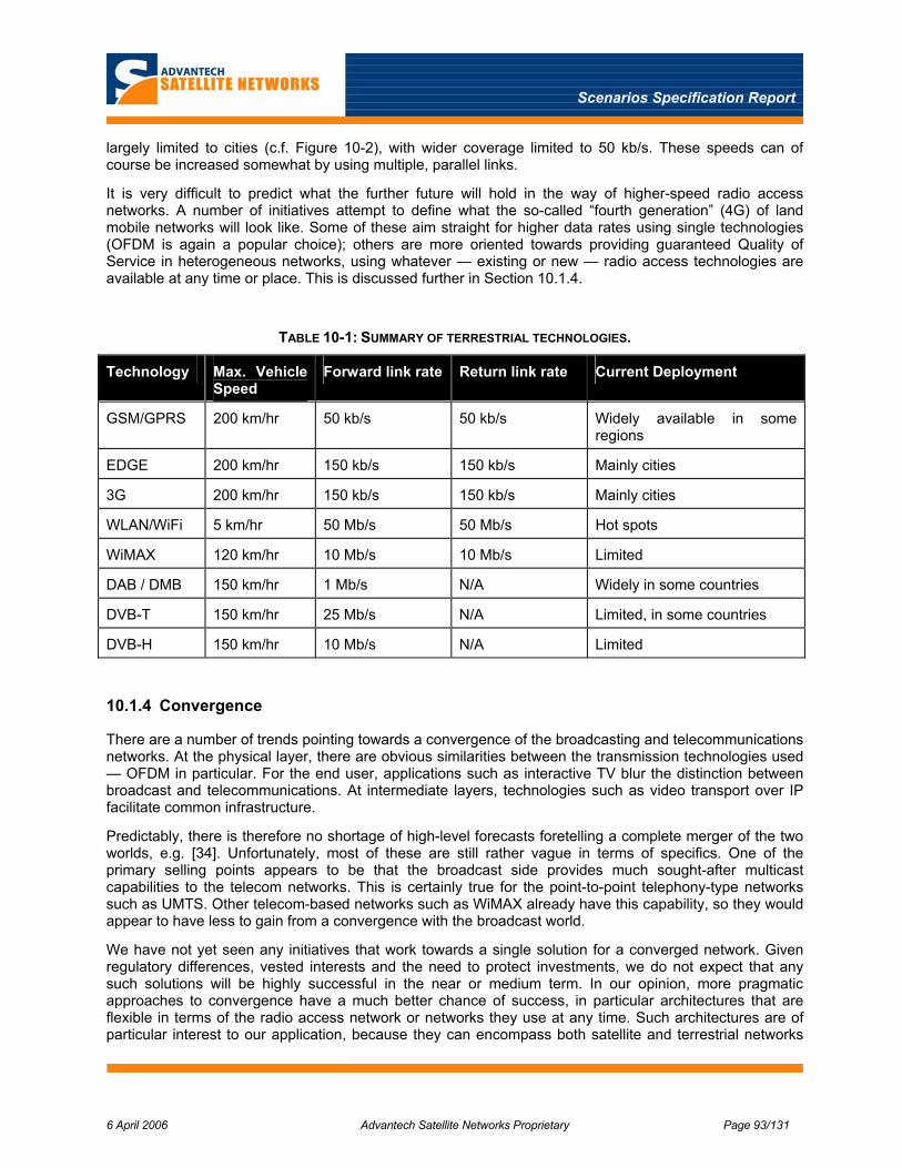
Scenarios Specification Report
6 April 2006 Advantech Satellite Networks Proprietary Page 93/131
largely limited to cities (c.f. Figure 10-2), with wider coverage limited to 50 kb/s. These speeds can of course be increased somewhat by using multiple, parallel links.
It is very difficult to predict what the further future will hold in the way of higher-speed radio access networks. A number of initiatives attempt to define what the so-called “fourth generation” (4G) of land mobile networks will look like. Some of these aim straight for higher data rates using single technologies (OFDM is again a popular choice); others are more oriented towards providing guaranteed Quality of Service in heterogeneous networks, using whatever — existing or new — radio access technologies are available at any time or place. This is discussed further in Section 10.1.4.
TABLE 10-1: SUMMARY OF TERRESTRIAL TECHNOLOGIES.
Technology Max. Vehicle Speed
Forward link rate Return link rate Current Deployment
GSM/GPRS 200 km/hr 50 kb/s 50 kb/s Widely available in some regions
EDGE 200 km/hr 150 kb/s 150 kb/s Mainly cities
3G 200 km/hr 150 kb/s 150 kb/s Mainly cities
WLAN/WiFi 5 km/hr 50 Mb/s 50 Mb/s Hot spots
WiMAX 120 km/hr 10 Mb/s 10 Mb/s Limited
DAB / DMB 150 km/hr 1 Mb/s N/A Widely in some countries
DVB-T 150 km/hr 25 Mb/s N/A Limited, in some countries
DVB-H 150 km/hr 10 Mb/s N/A Limited
10.1.4 Convergence
There are a number of trends pointing towards a convergence of the broadcasting and telecommunications networks. At the physical layer, there are obvious similarities between the transmission technologies used — OFDM in particular. For the end user, applications such as interactive TV blur the distinction between broadcast and telecommunications. At intermediate layers, technologies such as video transport over IP facilitate common infrastructure.
Predictably, there is therefore no shortage of high-level forecasts foretelling a complete merger of the two worlds, e.g. [34]. Unfortunately, most of these are still rather vague in terms of specifics. One of the primary selling points appears to be that the broadcast side provides much sought-after multicast capabilities to the telecom networks. This is certainly true for the point-to-point telephony-type networks such as UMTS. Other telecom-based networks such as WiMAX already have this capability, so they would appear to have less to gain from a convergence with the broadcast world.
We have not yet seen any initiatives that work towards a single solution for a converged network. Given regulatory differences, vested interests and the need to protect investments, we do not expect that any such solutions will be highly successful in the near or medium term. In our opinion, more pragmatic approaches to convergence have a much better chance of success, in particular architectures that are flexible in terms of the radio access network or networks they use at any time. Such architectures are of particular interest to our application, because they can encompass both satellite and terrestrial networks

Scenarios Specification Report
6 April 2006 Advantech Satellite Networks Proprietary Page 94/131
and therefore support our internetworking scenarios. A good example of such an architecture is the one deployed in the “Moby Dick” experiment [35]. A summary of this is provided in Appendix B.
In terms of implications for satellite-based mobile broadband services, we expect that the largest impact of converged architectures will come from these multi-network radio access architectures. These lend themselves naturally to the provision of complementary, terrestrial possibilities, precisely in the situations where satellites have problems (e.g., cities), where the likelihood of the existence of some form of terrestrial alternative is the largest. We address this point later in this report as so-called “Type 2" and "Type 3" gapfillers. We note however that a detailed investigation of this type of arrangement is outside the scope of the study.
10.2 Competition from Terrestrial Networks
The situation — both present and future — concerning terrestrial network alternatives to satellite-based delivery of mobile broadband services differs greatly among the considered environments. The following sub-sections assess the current situation and provide what we consider a probable outlook for each of the aeronautical, maritime and terrestrial environments.
10.2.1 Aeronautical
As discussed in Section 4, aeronautical customers undoubtedly form the most “captive audience” among the potential users. In-flight, terrestrial-based offerings to planes are currently largely limited to telephony and low-rate data services such as Terrestrial Flight Telecommunications System (TFTS, [36]). For long-haul flights, such services are also offered via satellite, usually Inmarsat.
We are not aware of any terrestrial-based broadband systems designed specifically for aeronautical use.
Furthermore, we do not envisage any fundamental changes to this situation. Aeronautical service is therefore a key target area for satellite-based delivery of broadband multimedia, relatively free of terrestrial competition. The anticipated size of this market is addressed in Section 4, and is expected to be limited to several thousand terminals. However, due to the lucrative and exclusive opportunity offered by the aeronautical market, this is being pursued as a primary target by all parties interested in providing mobile broadband services over satellite.
10.2.2 Maritime
Vessels on the high seas will not usually be able to access land-based services, and will be a “captive audience” for satellite-based delivery in much the same way as aeronautical users. However, large sections of the shipping industry operate in coastal waters, including most of the passenger traffic (yachts, ferries and cruise ships) that is of prime interest as potential customers. The composition and volume of this market is examined in Section 4, and is expected to be perhaps 10,000 terminals.
This is potentially important because there may be at least some coverage by land mobile networks for ships operating in coastal waters. At present, this is largely limited to cellular telephony networks, providing for example the GSM-based pay phones commonly available on ferries. It is of course possible that coastal-water coverage of 3G or other networks can be improved, should the operators recognise a potential market. One can envisage hybrid arrangements in which the forward link is satellite based and the return link uses lower-speed cellular networks, similar for example to the Icomera system used by Linx and others [37].
By nature, the ocean coverage of terrestrial networks will remain limited to a few kilometres offshore. Such networks may therefore reach some of the ferries, but will not be able to reach for example the cruise ships, which form a substantial part of the potential market identified in Section 4.
At present, there is therefore little terrestrial competition for satellite-based delivery of broadband to ships.
Scenarios Specification Report
6 April 2006 Advantech Satellite Networks Proprietary Page 95/131
In summary, we consider that there is a current window of opportunity for satellite-based service provision to ships. Furthermore, the characteristics of the maritime propagation environment are very similar to those of the aeronautical (i.e., Line-of-sight propagation), so the technical solutions will be similar. Therefore, these two applications can to a large extent be considered as a single market; there is no reason to exclude the maritime applications.
10.2.3 Land Mobile
The situation is less clear for the terrestrial environment. As described in Section 10.1, there are many land-based technologies already deployed or in development, which can provide many of the services envisaged in this environment.
For trains, the analysis presented in Section 4 estimates per-terminal aggregate data rate requirements of up to about 4 Mb/s in the forward direction and around 0.6 Mb/s in the return direction. Of the "native" two-way technologies, only WMAN (WiMAX) appears to be able to serve the needs of multi-user terminals in the forward direction (c.f. Table 10-1). DVB-T and DVB-H seem to be the best bets among the broadcast technologies. However, the deployment of all of these is currently rather limited, and the time scale for wider (e.g., Europe-wide) availability is not certain. The investment required to provide such coverage specifically for the mobile broadband service is very considerable. This points to satellite-based delivery of the forward link, given the relative ease of wide-area deployment of satellite services. A hybrid (satellite forward / terrestrial return) arrangement is exactly what has been adopted for example in the Icomera/Linx system.
For the return link, it is again only WMAN/WiMAX that appears to be able to meet the needs of the mobile terminals directly. However, the 3G technologies are not too far behind, and could possibly be fine-tuned for such use. For example, multiple parallel carriers can be used to increase the data rate.
In Europe, cellular network coverage is almost ubiquitous and return link solutions based on these are a viable option. However, in many parts of the world, including North America, there are large rural areas with no or only analogue cellular coverage. Given the low population densities in these areas, a rapid expansion of more performing networks is not likely to occur. In such areas, a satellite-based return link appear to be the only possibility in the short and medium term.
Eventually, deployment of terrestrial networks is likely to present a strong competition to satellite-based delivery. Once deployed, they will almost certainly be more cost effective than satellite. However, we do not anticipate that widespread deployment of networks such as WiMAX will take place until perhaps around 2012–2015. We base this prediction not on any technical arguments, but on the fact that operators are currently struggling to recover their investments in 3G networks, so it will be a while before the industry will be ready for substantial investments in yet another generation.
In terms of market size, the analysis in Section 4 indicates that the market just for trains in Europe has a size which is a substantial fraction of the world-wide aeronautical market. The potential worldwide terrestrial market is therefore likely to be quite large, in particular when other terrestrial forms of transport, such as buses or private vehicles, are included. The terrestrial market is therefore important and it appears that there is a definite place — even in Europe — for satellite-based delivery of broadband services to terrestrial mobile users in the short and medium term.
However, this conclusion is modulated by the fact that the terrestrial environment is by far the most troublesome in terms of channel characteristics, and therefore the one that will drive many of the characteristics of a satellite-based system — and hence eventually its cost. From this point of view, it is attractive to exclude the most demanding environments from consideration of satellite-based systems. It is interesting to note that the most demanding terrestrial channels are likely to be encountered in cities — which are the locations in which terrestrial alternatives are likely to be deployed first.
It is clear that any satellite system aimed at terrestrial users will need to be augmented by gapfillers. Even the otherwise more benign (e.g., rural) environments have gaps, such as tunnels through mountains, that
Scenarios Specification Report
6 April 2006 Advantech Satellite Networks Proprietary Page 96/131
will need to be filled in this way. As discussed in Section 11, the considerations for gapfillers also differ between the forward and return links. In particular, it is attractive to use an air interface on the return link gapfillers that does not differ too much from that of the satellite return link.
Given all these considerations, we reach the following overall conclusions about the functions that should be targetted for terrestrial applications and therefore should be part of our further study: • Forward link satellite services should be provided to all terrestrial environments, as necessary
augmented by gapfillers. Gapfillers should be able to operate even in the harshest terrestrial environments.
• Return link satellite services should be provided at least in the more benign environments, as necessary augmented by gapfillers. It may be acceptable to exclude the very worst environments from consideration of the return link service, given that these are the ones where terrestrial alternatives are or will be most readily available.
• Interworking with terrestrial networks is essential. This will eventually be needed for cost reasons, and may well be an attractive option in the shorter term for the provision of return link services in the worst propagation environments.
More specific, quantitative statements of what constitutes "benign" and "harsh" propagation environments can only be made when performance results from WP2.1.1 are available.
10.2.4 Summary
The assessment presented in the previous sub-sections has indicated that there appears to be a place for two-way satellite delivery of mobile broadband services in the short and medium term. For the aeronautical and maritime environments, terrestrial alternatives have little impact; satellite appears to be the only current possibility. For terrestrial environments, land mobile networks provide some alternatives, at least for the return connection in some densely populated regions such as Western Europe. Nevertheless, there appears to be a place for satellite also for terrestrial users, and provisions for these should be included, as summarised in Section 10.2.3 above. It is however important also to include interworking with terrestrial wireless networks, both to overcome some problems in the short term, and in order to embrace them as part of the solution in the future when they become more performing than they currently are.

Scenarios Specification Report
6 April 2006 Advantech Satellite Networks Proprietary Page 97/131
11 TERRESTRIAL GAP FILLERS
It is safe to predict, even without detailed analysis, that terrestrial gap-fillers are required in many situations where the propagation conditions are simply too severe for satellite signals. This section summarises the situation and makes recommendations for gap filler scenarios to be investigated in the main part of the study. The following analysis distinguishes between on the one hand gapfillers that are an integral part of the satellite-based network and on the other hand terrestrial networks used to extend the coverage. A hybrid model is also considered.
11.1 Type 1 — Integral Gapfiller
Integral gap fillers can be conceptually relatively straightforward, consisting essentially of radio repeaters that re-broadcast the forward link signals from the satellite and relay return link signals to the satellite. For both regulatory and technical reasons, they will sometimes use frequencies that are different from those used for the satellite link. It may therefore be necessary for the mobile terminal to have extra transmission and reception equipment in order to make use of the gap fillers. Figure 11-1 shows a conceptual block diagram of such a gapfiller. However, an interesting new regulatory development (USA FCC) in this regard has recently (2003) occurred which now allows satellite L (narrow)-band mobile systems to extend their reach via an Ancillary Terrestrial Component (ATC) [38]. The ATC essentially uses standard terrestrial technology, in this case cellular, while reusing satellite service-link RF frequencies. Band sharing is achieved by monitoring and dynamically controlling co-channel and adjacent channel interference levels. Whether such an approach can also eventually be applied to broadband mobile systems in Ku / Ka -band is not clear at this time.
Resource management for repeater-type integral gap fillers can in principle be quite simple. The resources available for the gap filler coverage are the same as those available in the satellite beam in which the gap filler is located. Handover to and from a gap filler is therefore simply a special type of intra-system handover, in which only physical layer parameters such as frequency and timing are changed. Given that the RF equipment will likely be different from that used for the satellite link proper, it should even be possible to make such handovers seamless — provided there is sufficient overlap in the coverage that a “make-before-break” handover can be implemented. There are aspects of the physical-layer arrangements that need further consideration as discussed below, in particular synchronisation. However, we do not see any fundamental difficulties with this type of arrangement. One main attractive property of this type of arrangement is that all higher-layer functions, including resource management, Quality-of-Service and AAA, are contained entirely within the same network. For integral gap fillers, there are therefore no specific inter-working aspects to consider for these network functions.
The above discussion implicitly assumes that the return link air interface is completely or nearly identical to the MF-TDMA air interface used on the satellite link. If this is not the case, the resource management for the gap fillers will be more similar to that required for different beams in the same network. The requirements and considerations are somewhat different for the forward and return links; these are therefore discussed separately in the following sub-sections.
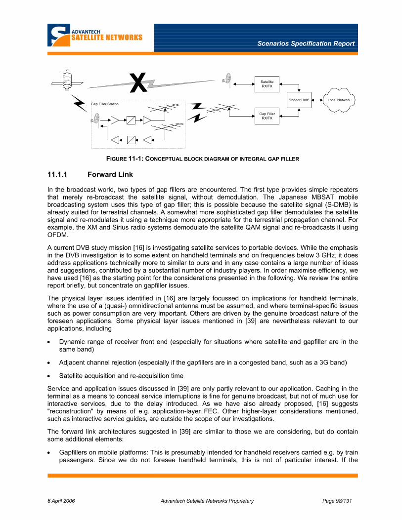
Scenarios Specification Report
6 April 2006 Advantech Satellite Networks Proprietary Page 98/131
XGap Filler Station
SatelliteRX/TX
Gap FillerRX/TX
"Indoor Unit" Local Network
FIGURE 11-1: CONCEPTUAL BLOCK DIAGRAM OF INTEGRAL GAP FILLER
11.1.1 Forward Link
In the broadcast world, two types of gap fillers are encountered. The first type provides simple repeaters that merely re-broadcast the satellite signal, without demodulation. The Japanese MBSAT mobile broadcasting system uses this type of gap filler; this is possible because the satellite signal (S-DMB) is already suited for terrestrial channels. A somewhat more sophisticated gap filler demodulates the satellite signal and re-modulates it using a technique more appropriate for the terrestrial propagation channel. For example, the XM and Sirius radio systems demodulate the satellite QAM signal and re-broadcasts it using OFDM.
A current DVB study mission [16] is investigating satellite services to portable devices. While the emphasis in the DVB investigation is to some extent on handheld terminals and on frequencies below 3 GHz, it does address applications technically more to similar to ours and in any case contains a large number of ideas and suggestions, contributed by a substantial number of industry players. In order maximise efficiency, we have used [16] as the starting point for the considerations presented in the following. We review the entire report briefly, but concentrate on gapfiller issues.
The physical layer issues identified in [16] are largely focussed on implications for handheld terminals, where the use of a (quasi-) omnidirectional antenna must be assumed, and where terminal-specific issues such as power consumption are very important. Others are driven by the genuine broadcast nature of the foreseen applications. Some physical layer issues mentioned in [39] are nevertheless relevant to our applications, including
• Dynamic range of receiver front end (especially for situations where satellite and gapfiller are in the same band)
• Adjacent channel rejection (especially if the gapfillers are in a congested band, such as a 3G band)
• Satellite acquisition and re-acquisition time
Service and application issues discussed in [39] are only partly relevant to our application. Caching in the terminal as a means to conceal service interruptions is fine for genuine broadcast, but not of much use for interactive services, due to the delay introduced. As we have also already proposed, [16] suggests "reconstruction" by means of e.g. application-layer FEC. Other higher-layer considerations mentioned, such as interactive service guides, are outside the scope of our investigations.
The forward link architectures suggested in [39] are similar to those we are considering, but do contain some additional elements:
• Gapfillers on mobile platforms: This is presumably intended for handheld receivers carried e.g. by train passengers. Since we do not foresee handheld terminals, this is not of particular interest. If the

Scenarios Specification Report
6 April 2006 Advantech Satellite Networks Proprietary Page 99/131
terminals in the systems we consider are connected to a wireless local access network (e.g., using WiFi), the entire terminal in our system can of course be perceived as a "mobile gapfiller".
• Distribution of the signal to gapfillers by satellite, but distinct from the direct-to-user satellite transmission. The advantage of this option is not clear to us; gapfillers should not have difficulties receiving the signals intended for individual terminals.
• Capability of local content insertion in gapfillers. This is potentially interesting, but not important for the investigations in the present study.
The analysis in [39] inherently assumes that gapfillers for Ku / Ka band systems will necessarily operate in different frequency bands. This is likely true in the short term; however, it may change if provisions similar to the L/S band ATC are adopted. For completeness, we have therefore considered all the options listed in [[39]. Our conclusions are not altered substantially by this.
The general and satellite-specific parameters to be considered for the physical layer design listed in [39] are substantially the same as those already identified in our earlier investigations, except for a few additional items targetted for handheld terminals, such as power consumption and the use of satellite diversity. The latter, while interesting, is not likely to be practical for systems that require high-gain antennas. Addition of a second outdoor unit, which is necessary for satellite diversity, is a major issue both in terms of cost and accommodation.
A number of candidate satellite/terrestrial transmission techniques are discussed in [16]. The main combinations are
• Solution A: OFDM for the satellite and terrestrial components
• Solution B: CDM for the satellite and terrestrial components (currently adopted by MBSAT system)
• Solution C: TDM for the satellite component & OFDM for the terrestrial component (currently adopted by XM and Sirius systems)
• Solution D: TDM for the satellite and terrestrial components
with a number of additional options listed for Ku / Ka band satellite operation:
• Solution E: DS/TDM
• Solution F: DS/CDM
• Solution G: OFDM-CDM
A number of advantages and disadvantages of the various options are discussed in [39]. We generally concur with the findings there, with the observation that the properties of solution "C" would apply equally well to a gapfiller component using CDM; for example, based on 3G wireless.
The DVB-SSP study report recognises that the use of DS/TDM (TDM signal with spread spectrum overlay, solution "E") is practically a given for the satellite forward link of interactive services networks catering to vehicular terminals. The report concurs with our preliminary conclusion that the DS/TDM air interface is not likely to be suitable for the gapfiller. The air interface for the gapfillers should be optimised separately, and will be different from that used on the satellite forward link. This points to a solution based on "C", but recognising the need for spectrum spreading in the satellite component. Further consideration of the air interface is deferred to Section 12, where all air interface considerations from the various sections of this report are consolidated.
The primary conclusion of our assessment of forward links for integral gapfillers is thus that these should perform a re-broadcast of the satellite signal, using an air interface optimised for the terrestrial channel.

Scenarios Specification Report
6 April 2006 Advantech Satellite Networks Proprietary Page 100/131
11.1.2 Return Link
For the return link, two very different situations will arise, depending on whether the MF-TDMA air interface is adequate. If the MF-TDMA air interface can be used, the return link of the gap filler will be a simple repeater. Should this not be the case, the return link of the gap filler will require adaptations, possibly even a complete modem development, for the selected air interface. In this case, it may even be advantageous to use dedicated satellite links for the return traffic, rather than mixing the gap filler traffic with the regular satellite return link traffic.
Using a different air interface will obviously contribute considerably to the development costs, as well as to the recurring cost of both the gap filler station and the user terminal. We will therefore try very hard to identify solutions that can make use of all or parts of the existing MF-TDMA return link air interface.
The different options are described in the following sub-sections, in decreasing order of attractiveness from an overall system complexity point of view.
11.1.2.1 Simple Translating Repeater
The gapfiller will have a complete replica of the return link bandwidth, and need only contain RF equipment for reception, frequency conversion (presumably up-conversion) and transmission. The main advantages of this arrangement are that no new modem development is required, and that it is completely transparent to all higher-level functions, including MAC layer scheduling, QoS, AAA etc. There are however a number of detailed issues that must be addressed, including
• Synchronisation: The TDMA system must allow for the additional delay on the gapfiller link; this is addressed below
• Linearity and dynamic range: The gapfiller must have sufficient dynamic range to handle the large variation of signal strength encountered on the terrestrial link and also to handle collisions; the latter is particularly important if a random-access component of the MAC layer scheme is adopted.
• Unwanted emissions: The gapfiller needs to be sufficiently free of unwanted emissions that it does not "pollute" the frequencies and time slots in which no actual transmissions take place to such an extent that they are unusable for direct terminal-to-satellite transmissions.
• Transmission levels and dynamics: The link budget of the gapfiller link will vary relatively much faster than the satellite link budget, potentially up to more than 40 dB/second. The situation is estimated in Appendix C. Special provisions will be necessary; this rate of variation can not likely be handled by the long-loop power control through the DVB-RCS hub.
11.1.2.2 Demodulating and Remodulating Repeater with Common Resources
In the event that the (spread) MF-TDMA air interface turns out not to be usable, or if insurmountable problems are encountered for example in handling the level variations, a dedicated air interface for the gapfiller link will be required. In that case, the adopted air interface should of course be one specifically suited to the gapfiller link; for example, OFDMA or CDMA.
It may be possible to replace the physical layer air interface without discarding the existing resource management methods altogether. This is the case if a unique translation between gapfiller and satellite transmission resources can be defined. For example, time/frequency slots on the satellite link can be mapped to time slots in an OFDMA system or to specific codes in a CDMA system. The mapping can be signalled to the terminal and gapfiller as part of the network information.
In such an arrangement, the terminal will know how to translate capacity assignments given in terms of the satellite link to gapfiller resources and thus when and where to transmit; and the gapfiller will know when and where to re-transmit the information received from the mobile terminal as part of the satellite air
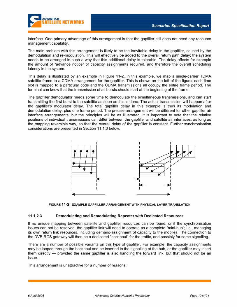
Scenarios Specification Report
6 April 2006 Advantech Satellite Networks Proprietary Page 101/131
interface. One primary advantage of this arrangement is that the gapfiller still does not need any resource management capability.
The main problem with this arrangement is likely to be the inevitable delay in the gapfiller, caused by the demodulation and re-modulation. This will effectively be added to the overall return path delay; the system needs to be arranged in such a way that this additional delay is tolerable. The delay affects for example the amount of “advance notice” of capacity assignments required, and therefore the overall scheduling latency in the system.
This delay is illustrated by an example in Figure 11-2. In this example, we map a single-carrier TDMA satellite frame to a CDMA arrangement for the gapfiller. This is shown on the left of the figure; each time slot is mapped to a particular code and the CDMA transmissions all occupy the entire frame period. The terminal can know that the transmission of all bursts should start at the beginning of the frame.
The gapfiller demodulator needs some time to demodulate the simultaneous transmissions, and can start transmitting the first burst to the satellite as soon as this is done. The actual transmission will happen after the gapfiller's modulator delay. The total gapfiller delay in this example is thus its modulation and demodulation delay, plus one frame period. The precise arrangement will be different for other gapfiller air interface arrangements, but the principles will be as illustrated. It is important to note that the relative positions of individual transmissions can differ between the gapfiller and satellite air interfaces, as long as the mapping reversible way, so that the overall delay of the gapfiller is constant. Further synchronisation considerations are presented in Section 11.1.3 below.
FIGURE 11-2: EXAMPLE GAPFILLER ARRANGEMENT WITH PHYSICAL LAYER TRANSLATION
11.1.2.3 Demodulating and Remodulating Repeater with Dedicated Resources
If no unique mapping between satellite and gapfiller resources can be found, or if the synchronisation issues can not be resolved, the gapfiller link will need to operate as a complete "mini-hub"; i.e., managing its own return link resources, including demand-assignment of capacity to the mobiles. The connection to the DVB-RCS gateway will then be a dedicated "backhaul" for the traffic, and possibly for some signalling.
There are a number of possible variants on this type of gapfiller. For example, the capacity assignments may be looped through the backhaul and be inserted in the signalling at the hub, or the gapfiller may insert them directly — provided the same gapfiller is also handling the forward link, but that should not be an issue.
This arrangement is unattractive for a number of reasons:
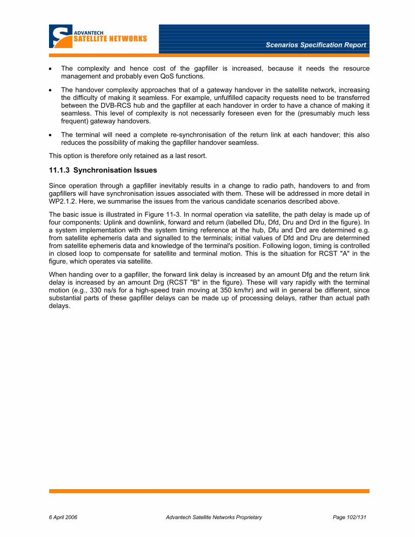
Scenarios Specification Report
6 April 2006 Advantech Satellite Networks Proprietary Page 102/131
• The complexity and hence cost of the gapfiller is increased, because it needs the resource management and probably even QoS functions.
• The handover complexity approaches that of a gateway handover in the satellite network, increasing the difficulty of making it seamless. For example, unfulfilled capacity requests need to be transferred between the DVB-RCS hub and the gapfiller at each handover in order to have a chance of making it seamless. This level of complexity is not necessarily foreseen even for the (presumably much less frequent) gateway handovers.
• The terminal will need a complete re-synchronisation of the return link at each handover; this also reduces the possibility of making the gapfiller handover seamless.
This option is therefore only retained as a last resort.
11.1.3 Synchronisation Issues
Since operation through a gapfiller inevitably results in a change to radio path, handovers to and from gapfillers will have synchronisation issues associated with them. These will be addressed in more detail in WP2.1.2. Here, we summarise the issues from the various candidate scenarios described above.
The basic issue is illustrated in Figure 11-3. In normal operation via satellite, the path delay is made up of four components: Uplink and downlink, forward and return (labelled Dfu, Dfd, Dru and Drd in the figure). In a system implementation with the system timing reference at the hub, Dfu and Drd are determined e.g. from satellite ephemeris data and signalled to the terminals; initial values of Dfd and Dru are determined from satellite ephemeris data and knowledge of the terminal's position. Following logon, timing is controlled in closed loop to compensate for satellite and terminal motion. This is the situation for RCST "A" in the figure, which operates via satellite.
When handing over to a gapfiller, the forward link delay is increased by an amount Dfg and the return link delay is increased by an amount Drg (RCST "B" in the figure). These will vary rapidly with the terminal motion (e.g., 330 ns/s for a high-speed train moving at 350 km/hr) and will in general be different, since substantial parts of these gapfiller delays can be made up of processing delays, rather than actual path delays.

Scenarios Specification Report
6 April 2006 Advantech Satellite Networks Proprietary Page 103/131
Hub
RCST A GapFiller
RCST B
DfuDfd
Dfg
Drg
DruDrd
FIGURE 11-3: BASIC SYNCHRONISATION ISSUES WITH GAPFILLERS.
11.1.3.1 Forward Link
Since both gapfiller and satellite forward links use continuous signals, the issues are very similar to those encountered in handovers between satellite beams. The primary goal is to avoid a discontinuity in the received NCR clock, which may cause the terminal to log off as a safety measure.
A method for NCR synchronisation maintenance during a break-before-make forward link handover has already been devised by Advantech Satellite Networks. In addition to mobility, initial applications of this technique include redundancy switching and (pre-DVB-S2) rain fade countermeasure schemes. Some details are provided in Appendix D; the basic idea is to let the terminal's NCR clock free-wheel while no signal is present, and then apply a one-off offset to the values received in the new forward link that eliminates any discontinuity. This method was chosen because it is in practice very difficult to ensure identical path delays even between pairs of nominally identical forward links. The method can however be extended trivially to gapfiller operation.
11.1.3.2 Return Link
If the gapfiller return link is a simple frequency translation, the additional return link delay is likely dominated by actual path delay. Furthermore, its relationship to the additional forward link delay can often be known with some accuracy — provided the forward link additional delay is made up of a constant element (processing) and a propagation delay. An initial estimate can therefore be obtained from the offset applied to the forward link for NCR synchronisation maintenance. A precise correction can be applied, for example by transmitting a few ACQ bursts. The details are for further study in WP2.1.2, using available information about the equipment delay that can be expected.
The situation is a little more complicated for a demodulating and re-modulating gapfiller as described in Section 11.1.2.2. The conventional closed-loop method cannot be used, because the terminal does not actually transmit DVB-RCS bursts that eventually reach the hub. The gapfiller demodulator will however be able to determine the timing of the transmission received from the terminal; it will necessarily do so in order to demodulate them. We assume for now that the gap filler air interface operates on a framing structure

Scenarios Specification Report
6 April 2006 Advantech Satellite Networks Proprietary Page 104/131
that is related to the DVB-RCS frames. The timing offsets thus measured can be signalled to the hub through some dedicated capacity. Alternatively, they can be signalled indirectly by letting the gapfiller transmit the DVB-RCS bursts with precisely controlled offsets that mimic those measured on the gap filler air interface, possibly scaled to account for differences in the two air interfaces. The first method is easier to implement in the gapfiller. It does however require the hub to be aware that the terminal operates through a gapfiller, so that it can take the offset information from signalling rather than measuring it. it also requires a (small) amount of signalling capacity. The second method requires more effort in the gapfiller, but is completely transparent to the hub. This will be investigated further in WP2.1.2, taking into account the properties of actual candidate gapfiller air interface techniques.
If a coarse estimate of the return link additional delay is available (e.g., from knowledge of the equipment and the forward link path delay offset), ACQ bursts or their equivalent in the gapfiller air interface can again be used for an initial estimate and correction process.
Gapfillers that manage the return link resource on their own will also need to manage the synchronisation of the terminals. It will be necessary to define a logon process for this air interface. Some knowledge of timing can presumably be retained, especially if the gapfiller operates on a timing reference related to that used for the satellite link.
In summary, we have outlined system synchronisation solutions for all the candidate gapfiller scenarios. We expect that the choice of air interface will be driven by the basic demodulation performance in the terrestrial channel. This will drive the choice of gapfiller scenario, and a synchronisation scheme appropriate for this will be chosen and elaborated.
11.2 Type 2 — Terrestrial Gapfiller
We use this term to refer to terrestrial wireless networks used as a complete replacement for the satellite transmission. Whether this is called "gapfilling" or "terrestrial interworking" is really a matter of semantics. This type of operation may be desirable for example where the vehicle’s route passes through regions that provide coverage of terrestrial networks, as well as regions that do not. Where available, terrestrial alternatives are often more cost effective than satellite connections, so it may be desirable to use them when possible. An example applications scenario for this type of system is a North American trans-continental high-speed train. Terrestrial coverage will likely be available in and around larger cities, but not in the rural areas in between.
The types of terrestrial networks that are likely candidates for this type of operation are discussed in Section 10; an example of a network architecture that makes use of multiple radio networks is given in Appendix B.
Fully-fledged inter-working with terrestrial networks is much more complex than the Type 1 integral gapfiller arrangement outlined in Section 11.1 above. The terminal needs to choose an appropriate access network from among those available at any time. The access networks are typically heterogeneous, with differences in the ways fundamental aspects such as mobility and Quality-of-Service are handled. Figure 11-4 shows a conceptual block diagram of a service that can use multiple networks. The end user’s equipment accesses the vehicular terminal through a local network, typically an on-board wireless or wired LAN. The traffic is routed through one or more access networks to the “home” network, from which it is passed to the wider Internet through the network’s edge router(s). The “home” network typically belongs to the service provider for the mobile end-user service, or to a network provider who sells transport capacity to a number of service providers.
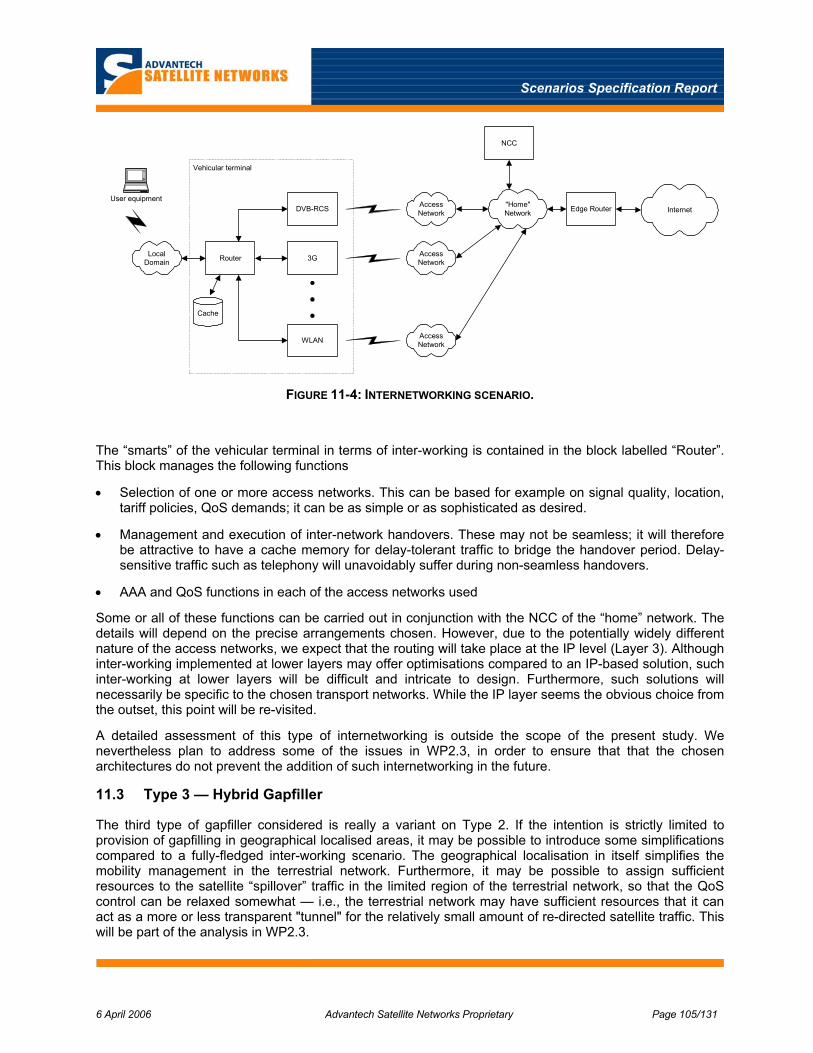
Scenarios Specification Report
6 April 2006 Advantech Satellite Networks Proprietary Page 105/131
LocalDomain Router
User equipmentDVB-RCS
3G
WLAN
Cache
AccessNetwork
AccessNetwork
AccessNetwork
"Home"Network Edge Router Internet
NCC
Vehicular terminal
FIGURE 11-4: INTERNETWORKING SCENARIO.
The “smarts” of the vehicular terminal in terms of inter-working is contained in the block labelled “Router”. This block manages the following functions
• Selection of one or more access networks. This can be based for example on signal quality, location, tariff policies, QoS demands; it can be as simple or as sophisticated as desired.
• Management and execution of inter-network handovers. These may not be seamless; it will therefore be attractive to have a cache memory for delay-tolerant traffic to bridge the handover period. Delay-sensitive traffic such as telephony will unavoidably suffer during non-seamless handovers.
• AAA and QoS functions in each of the access networks used
Some or all of these functions can be carried out in conjunction with the NCC of the “home” network. The details will depend on the precise arrangements chosen. However, due to the potentially widely different nature of the access networks, we expect that the routing will take place at the IP level (Layer 3). Although inter-working implemented at lower layers may offer optimisations compared to an IP-based solution, such inter-working at lower layers will be difficult and intricate to design. Furthermore, such solutions will necessarily be specific to the chosen transport networks. While the IP layer seems the obvious choice from the outset, this point will be re-visited.
A detailed assessment of this type of internetworking is outside the scope of the present study. We nevertheless plan to address some of the issues in WP2.3, in order to ensure that that the chosen architectures do not prevent the addition of such internetworking in the future.
11.3 Type 3 — Hybrid Gapfiller
The third type of gapfiller considered is really a variant on Type 2. If the intention is strictly limited to provision of gapfilling in geographical localised areas, it may be possible to introduce some simplifications compared to a fully-fledged inter-working scenario. The geographical localisation in itself simplifies the mobility management in the terrestrial network. Furthermore, it may be possible to assign sufficient resources to the satellite “spillover” traffic in the limited region of the terrestrial network, so that the QoS control can be relaxed somewhat — i.e., the terrestrial network may have sufficient resources that it can act as a more or less transparent "tunnel" for the relatively small amount of re-directed satellite traffic. This will be part of the analysis in WP2.3.

Scenarios Specification Report
6 April 2006 Advantech Satellite Networks Proprietary Page 106/131
11.4 Summary
Integral gapfillers are the primary focus of the study. We have summarised other work (DVB TM-SSP) currently in progress for integrated satellite/terrestrial broadcast networks and have found that our forward link needs appear to be covered by a subset of those considered there. The situation is less mature for the return link; we have postulated a number of different candidate arrangements for return link gapfillers. The choice will depend on the required robustness of the gapfiller physical layer air interface. We have identified synchronisation solutions for all the proposed arrangements.
As an alternative, we have proposed the use of terrestrial networks proper as a means of complementing the satellite coverage. This need not be restricted to gapfilling functions, but may be attractive anyway from a cost efficiency point of view. One drawback of this type of solution is likely that inter-network handovers are likely to cause more interruption than intra-network gapfiller handovers.
Scenarios Specification Report
6 April 2006 Advantech Satellite Networks Proprietary Page 107/131
12 PRELIMINARY AIR INTERFACE CONSIDERATIONS
Comprehensive investigations of physical and MAC layer air interface issues will take place in subsequent work packages: Critical issues will be identified in WP1.2, and detailed assessments will be carried out in WP2.1 and WP2.2. However, as described in the preceding chapters in this report, both regulatory and physical constraints have a strong influence on the air interface, which in turn drives important choices for certain parts of the system architecture. As a result of this, it is possible already now to list a number of air interface issues that need further investigation, as well as stating a number of open questions. Rather than artificially deferring this information to the WP1.2 outputs, we capture in this section what is already known in this important area. Starting from the DVB-RCS reference architecture, we discuss the air interface issues for each link separately.
12.1 Satellite Air Interface
Investigations so far in both our and other studies such as MOWGLY, as well as initial considerations for integrated satellite/terrestrial broadcasting have reached quite similar conclusions concerning the satellite air interface. The design is largely conditioned by a line-of-sight channel, with the proviso that terrestrial gapfillers will be used to aid in severely shadowed and blocked channels.
12.1.1 Forward Link
Without external constraints, a basic TDM scheme such as DVB-S/S2 could well be used unmodified for the forward link. However, due to the limited size of the antenna aperture that is practical to use in particular on aircraft and trains, spectrum spreading is required in order to mitigate adjacent-satellite interference. Maritime applications can generally operate without this spreading.
Our previous work has identified simple direct-sequence spreading as the method of choice, using a PN sequence in a simple "bolt-on" arrangement, which preserves the possibility of using standard demodulator ASICs after de-spreading. Spreading factors range from 1 to about 8, with signals typically occupying up to a complete transponder (~ 28 MChips/s in Ku -band).
Initial designs, including considerations of (re-)synchronisation times, have already been made in previous work. These will be brought in as required in later work packages.
Further work in this area will include investigations of the extent to which this air interface can be used on satellite/terrestrial channels. This will contribute to the determination of the need for gapfillers. For example, the spectrum spreading may be useful against mild multipath propagation, but is not likely to be adequate for all situations. The investigations will include modest modifications of the current standards that may help the relatively low-rate carriers needed for the mobile application. This may for example include optimised pilot distributions. The possibility of such modifications is being considered by DVB [39].
The further work will also include considerations of adaptive coding and modulation. The spectral efficiency of the spread-spectrum forward link is by nature very low, compared to conventional systems — is it not possible to use multiple access (e.g., CDMA), since this would defeat the purpose of the spectrum spreading. Improvements in the spectral efficiency can therefore have very large advantages in terms of absolute space segment cost. Such techniques should therefore be investigated for the satellite link, with due considerations of the limitations that may be imposed by the potentially very rapid channel variations. We expect that the major issues with ACM will be encountered at higher layers, rather than at the physical layer.
12.1.2 Return Link
The basic DVB-RCS air interface could be used for mobile return link transmissions on line-of-sight channels, if helped a bit on specific points such as Doppler compensation. Regulatory constraints however

Scenarios Specification Report
6 April 2006 Advantech Satellite Networks Proprietary Page 108/131
dictate that spectrum spreading is needed, mainly in order to meet off-axis power flux density limits; i.e., to reduce interference to adjacent satellites.
Our previous work also resulted in the choice of direct-sequence spreading for the return link, using minor modifications and keeping the chip rate within what current terminals can typically support as their symbol rate (around 5 MChips/s). Spreading factors vary from 1 (for maritime) up to about 20. The major issue here is the synchronisation of the spread bursts; we identified complex but feasible solutions for this.
Further work in this area will include investigations of the extent to which this air interface can be used on satellite/terrestrial channels. This will contribute to the determination of the need for gapfillers. The work will also address potential simplification of the modem algorithms used to receive the spread-spectrum signal.
12.2 Gap Filler Air Interface
As pointed out in previous sections, there will be situations where the properties of the satellite/terrestrial channel will prevent the satellite air interface from working adequately. These include locations where the satellite channel is completely blocked. In such situations, a dedicated gap filler air interface should be used; this should be optimised to the terrestrial channel proper. More-or-less suitable terrestrial wireless standards already exist; we do therefore not anticipate designing a new terrestrial air interface from scratch. We address here only the air interface for integral, "Type 1" gapfillers.
12.2.1 Forward Link
There is currently significant interest in mobile applications for broadcast within the DVB consortium. One result of this is the recent "study mission" on satellite service to portable devices (SSP) [39], which has looked at how existing DVB standards can be combined to provide such services, possibly with minor modifications.
As described above, DVB-S2 with spread spectrum overlay is the obvious choice for the satellite forward link. Of the DVB standards, DVB-T and DVB-H are — for our purposes — about equally well suited for the gapfiller component. The DVB-SSP report leans towards DVB-H, because of its better support for handheld terminals (In particular, the power-saving possibilities offered by the time-slicing options). We note that appropriate modifications of both DVB-S2 and DVB-H are being considered.
The applications and forward link architectures of the systems we are considering are thus a subset of what is being considered in the DVB-SSP report. In order to minimise duplication of work and the number of similar standards, considerations for the forward link of the DVB-RCS mobile standard should be coordinated with the DVB-SSP work. One consideration in this will be to ensure that the adopted solutions are not so heavily driven by the need to provide service to handheld terminals that either vehicle-mounted terrestrial applications or the aeronautical and maritime environments suffer excessively.
In summary, we recommend that the investigations of the physical layer for the forward link in this study concentrate on DVB-H with enhanced FEC (application layer, perhaps also physical-layer). In order to minimise system synchronisation problems, the investigations will include exploration of techniques that minimise the demodulation/modulation delay in the gapfiller. For example, the gapfiller may have a much better link budget than mobile terminals in the same beam, so it may be possible to reduce the number of LDPC decoder iterations for the DVB-S2 signal.
12.2.2 Return Link
As discussed in Section 11.1.2, there is a strong dependency between the characteristics of air interface on the gapfiller return link and the whole architecture of this device and the way it is operated. The first issue to address is therefore to determine what kind of air interface should be used.
Scenarios Specification Report
6 April 2006 Advantech Satellite Networks Proprietary Page 109/131
We do not fully expect that the spread DVB-RCS air interface will be adequate. Nevertheless, the extent to which this can be used on the terrestrial channel should be determined. As mentioned in Section 10, we anticipate that terrestrial alternatives will be available first in cities — which is exactly where the worst propagation conditions are expected. Should the spread DVB-RCS air interface turn out to be adequate for less demanding environments (e.g., the "tunnel through the mountains"), it opens up the possibility of relying on this for the less demanding environments and using terrestrial networks proper in the worst locations. As described in Section 11, using the spread DVB-RCS air interface in the return link gapfillers is very attractive from a system complexity point of view.
It is more likely however that we will need to design a proper air interface for the terrestrial gapfiller return channel. This work should rely on existing designs and standards to the largest extent possible. As described in Section 11.1.2, it is however important that we can arrange the MAC layer such that there is a unique mapping between resources in DVB-RCS and those of the gapfiller air interface.
Scenarios Specification Report
6 April 2006 Advantech Satellite Networks Proprietary Page 110/131
13 SUMMARY AND RECOMMENDATIONS
This report has brought together previous work in the area of mobile satellite broadband systems as well as some of the fundamental parameters that govern the intended applications; including applications and markets, traffic volumes and characteristics, physical constraints such as channel characteristics and regulatory constraints, as well as the expected competition and/or synergies with terrestrial alternatives.
From this database, overall system characteristics have been determined for a number of application scenarios. The report describes the space, ground and gapfiller segments, as well as a number of characteristics of the physical layer air interface, which is closely interlinked with the system architecture.
This selection of "reference scenarios" will be used for the further system design and optimisation work. The next step is the more detailed identification of technical issues to be investigated, including where possible a pre-selection to reduce the number of options that must be investigated in detail. Specific recommendations for topics to be investigated or parameters to be used in the next stages are contained in the individual chapters above; these are not repeated here.
Significantly, the next step (WP1.2) will also start to bring in networking issues at all levels (mobility management, resource management, QoS, AAA). These issues have not been addressed in any detail in this first assessment.
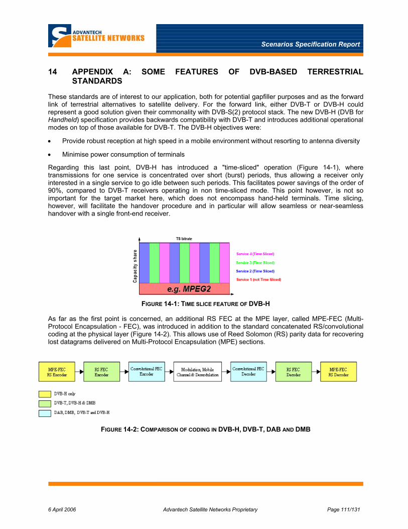
Scenarios Specification Report
6 April 2006 Advantech Satellite Networks Proprietary Page 111/131
14 APPENDIX A: SOME FEATURES OF DVB-BASED TERRESTRIAL STANDARDS
These standards are of interest to our application, both for potential gapfiller purposes and as the forward link of terrestrial alternatives to satellite delivery. For the forward link, either DVB-T or DVB-H could represent a good solution given their commonality with DVB-S(2) protocol stack. The new DVB-H (DVB for Handheld) specification provides backwards compatibility with DVB-T and introduces additional operational modes on top of those available for DVB-T. The DVB-H objectives were:
• Provide robust reception at high speed in a mobile environment without resorting to antenna diversity
• Minimise power consumption of terminals
Regarding this last point, DVB-H has introduced a "time-sliced" operation (Figure 14-1), where transmissions for one service is concentrated over short (burst) periods, thus allowing a receiver only interested in a single service to go idle between such periods. This facilitates power savings of the order of 90%, compared to DVB-T receivers operating in non time-sliced mode. This point however, is not so important for the target market here, which does not encompass hand-held terminals. Time slicing, however, will facilitate the handover procedure and in particular will allow seamless or near-seamless handover with a single front-end receiver.
FIGURE 14-1: TIME SLICE FEATURE OF DVB-H
As far as the first point is concerned, an additional RS FEC at the MPE layer, called MPE-FEC (Multi-Protocol Encapsulation - FEC), was introduced in addition to the standard concatenated RS/convolutional coding at the physical layer (Figure 14-2). This allows use of Reed Solomon (RS) parity data for recovering lost datagrams delivered on Multi-Protocol Encapsulation (MPE) sections.
FIGURE 14-2: COMPARISON OF CODING IN DVB-H, DVB-T, DAB AND DMB

Scenarios Specification Report
6 April 2006 Advantech Satellite Networks Proprietary Page 112/131
The MPE-FEC Frame is arranged as a matrix with 255 columns and a flexible number of rows8 (Figure 14-3).
The first 191 columns carry the application layer datagrams (Figure 14-4). Once a section has been filled (possibly with some zero padding), the parity section is computed, considering each row as a (255, 191) RS code. Up to 64 missing columns9 can thus be recovered at the receiver, counteracting loss of datagrams due to blockage. This is feasible because of the time interleaving functions of the MPE-FEC. It can be observed that, depending on the selected parameters, time interleaving will typically span periods from 50 to 500 ms.
FIGURE 14-3: MPE-FEC ORGANISATION
FIGURE 14-4: APPLICATION LAYER DATAGRAM ORGANISATION FOR MPE-FEC
8 The maximum allowed number of rows is 1024, which makes the maximum MPE-FEC frame size equal to 2 Mbits. 9 The recoverable number of datagrams is variable, depending on the average number of datagrams contained in each column.

Scenarios Specification Report
6 April 2006 Advantech Satellite Networks Proprietary Page 113/131
TABLE 14-1: DVB-T SFN CELL RADIUS (8 MHZ CHANNEL)
FFT Mode Guard Time
Guard Time (µs) SFN Cell Radius (km)
8k
1/4 1/8 1/16 1/32
224 112 56 28
67.2 33.6 16.8 8.4
2k
1/4 1/8 1/16 1/32
56 28 14 7
16.8 8.4 4.2 2.1
4k
1/4 1/8 1/16 1/32
112 56 28 14
33.6 16.8 8.4 4.2
Finally, a 4K FFT mode (4096 carriers) was added to the original 2K and 8K modes in DVB-T, for greater flexibility in coping with different requirements in terms of Doppler shift and cell size scenarios.
If a Single Frequency Network (SFN) is implemented, the choice of the DVB-T (H) operating mode is dictated by the desired cell size and admissible mobile speed. The cell size is related to the guard time assumed in the operating mode, as the multiple transmitters in an SFN network introduce an artificial multipath whose worst case delay spread is comparable to the cell radius [A1]. Table 14-1 shows the resulting cell size for DVB-T(H) in the different operating modes.
The admissible mobile speed is inversely related to the FFT size. Doppler frequency shift introduces a loss of orthogonality between the different carriers, which worsens with the ratio between the carrier Doppler shift and frequency separation of the OFDM carriers. Such a loss of orthogonality introduces interference between the carriers, which is referred as ICI (Inter-Carrier Interference).
The 2K modes of DVB-T can thus cope with 4 times higher Doppler shift than 8K modes, due to the 4 times larger carrier-spacing it produces. Actual degradation will also depend on the code rate and modulation format (more efficient modulation/coding are somewhat more sensitive to Doppler) as well as on adopted countermeasures (e.g. antenna diversity). However, a budgetary limit for Doppler shift can be assumed equal to 50 Hz for the 8 K mode and 200 Hz for the 2 K mode.
Reference
[A1] H. Yaghoobi, Scalable OFDMA Physical layer in IEEE 802.16 Wireless MAN”, Intel Technology Journal, vol. 8, Issue 3, 2004, pp.201–212.

Scenarios Specification Report
6 April 2006 Advantech Satellite Networks Proprietary Page 114/131
15 APPENDIX B: EXAMPLE HETEROGENEOUS NETWORK ARCHITECTURE
This appendix provides a summary of the network architecture adopted in the EC programme “Moby Dick”. It is relevant to our study as a potential gap filler arrangement and as a potential inter-working scenario in situations where terrestrial wireless networks are used to complement the satellite delivery. The appendix therefore also discusses elements of the usefulness of this type of model for our application.
15.1 Summary of Moby Dick
“Moby Dick” was carried out by a consortium including Deutsche Telekom, NEC and Motorola. The project was finished in 2004; more detailed information can be found in [B1]. This project addressed terrestrial wireless IP networks only; however, satellite IP networks can be handled in the same framework. A forum called the Open Mobile Alliance (OMA) [B2] is developing open standards for a number of the issues addressed by Moby Dick. This organisation is a successor of the Mobile Wireless Internet Forum (MWIF).
The basic architecture of "Moby Dick" is shown in Figure 15-1 (from [B3]). It uses the same concept of "home" and "visited" network as GSM and UMTS. The user's terminal can access through any of the available wireless networks. Distributed, mobility-aware AAA and QoS servers interact with the user's Home Agent to set up appropriate resources and configurations — and to arrange for charging and billing. Traffic is typically routed to the user's home network through the backbone connecting the participating networks. A Paging Agent connected to the backbone allows network-originated sessions to reach the mobile subscriber. Because the entire structure is created at IP-level and above, it is somewhat independent of the underlying transport mechanisms. However, this independence is not complete; in particular with respect to mobility within one network.
FIGURE 15-1: MOBY DICK ARCHITECTURE.
The architecture described above represents only a modest part of the overall work carried out in the Moby Dick project. A very substantial element of the project dealt with ways of ensuring homogeneous service and application presentation and performance across the heterogeneous collection of networks. It is this work in particular which is being continued and standardised in the Open Mobile Alliance. While essential for eventual operational arrangements, this aspect is well beyond the scope of the present study.

Scenarios Specification Report
6 April 2006 Advantech Satellite Networks Proprietary Page 115/131
15.2 Mobility Management
One of the first issues that needs to be addressed in this type of heterogeneous environment is mobility management. “Moby Dick” decided on a solution based on Mobile IP. This is certainly one candidate also for our application, but not the only one. First of all, mobile IP needs adaptation functions in order to map it to the “native” mobility management found in most networks. For example, GSM/GPRS/EDGE has a mobility management scheme based on MAC layer functions. This scheme has been adapted to packet services, but has its roots firmly in systems optimised for circuit-switched voice. Adaptation or “convergence” functions need to be defined for each network that has its own mobility function.
Furthermore, the basic Mobile IP is intended more for nomadic, wired access than for wireless mobility. As a result of this, handover times can easily reach 10 seconds or more. Moby Dick implemented a fast, make-before-break handover protocol, which overcomes some of these issues. However, they needed to use some components in non-standard ways in order to achieve this. This is a point to be checked in WP2.3.
For our application, it may in any case not be necessary to go to the full functionality of mobile IP. Handover between satellites is also associated with handover between gateways. This is practically equivalent to a handover between networks and can be accomplished without going to the full complexity of mobile IP. Having said that, the satellite networks carried over the different satellites are of course relatively homogeneous in nature; for example, a terminal using a DVB-RCS network before the handover will likely want to use another DVB-RCS network after the handover. The terrestrial networks will be more heterogeneous, so the more finely honed solution may not be possible. Nevertheless, it is conceivable that the mobility management can be simplified, compared to a full mobile IP solution.
15.3 QoS and AAA
The second major issue encountered when working with multiple, heterogeneous networks is that of Quality of Service. “Moby Dick” defined a QoS architecture based on DiffServ, augmented by distributed QoS broker functions located in the individual access networks. The purpose of these is to ensure a sufficiently fine control of the QoS. This QoS architecture is very similar to that defined by Advantech Satellite Networks for both fixed and mobile DVB-RCS networks, so this general type of arrangement will form the baseline assumption. We will seek simplifications where possible, in particular with a view to minimise the impact on the terrestrial networks.
A third element that will need to be addressed in order to implement an operational network is AAA (Authentication, Administration and Accounting). In parallel to the mobility and QoS functions, this aspect needs adaptation functions in order to operate with the “native” AAA in the heterogeneous terrestrial networks.
15.4 References
[B1] http://www.ist-mobydick.org/
[B2] http://www.openmobilealliance.org
[B3] IST-2000-25394, Project Moby Dick: "Mobility and Differentiated Services in a Future IP Network: Final Project Report", April 4, 2004. Available through [B1].

Scenarios Specification Report
6 April 2006 Advantech Satellite Networks Proprietary Page 116/131
16 APPENDIX C: GAPFILLER SIGNAL LEVEL DYNAMICS
The path loss between a mobile terminal and a gapfiller can vary much faster than is normally encountered in geostationary satellite links. This appendix estimates the worst case likely to be encountered in the applications considered.
FIGURE 16-1: GAPFILLER GEOMETRY.
Consider a gapfiller for a high-speed train line. The geometry is illustrated in Figure 16-1. Assume that the gapfiller is located 10m from the train track, and that the cell radius is 10 km. We've used an example frequency of 3 GHz; however, this is not important for the considerations of relative levels. At 10 m distance, the free space path loss is 62 dB; at 10 km, it is 122 dB. We thus have a dynamic range of 60 dB (=20 log10(10000/10)).
The maximum speed considered for high-speed trains is 350 km/hr, ~ 100 m/s. In the first second after passing the gapfiller, the range varies from 10 to (just over) 100m; i.e., a change of 20 dB. In the last second before the train reaches the edge of the cell, the change is < 0.1 dB.
A more detailed analysis reveals that the peak rate of change for this example is in fact just over 43 dB/s, as illustrated in Figure 16-2.
0 0.1 0.2 0.3 0.4 0.5 0.6 0.7 0.8 0.9 10
5
10
15
20
25
30
35
40
45
50
Time (s)
Pat
h lo
ss v
aria
tion
(dB
/s)
FIGURE 16-2: PATH LOSS VARIATION IN FIRST SECOND AFTER PASSING GAPFILLER.
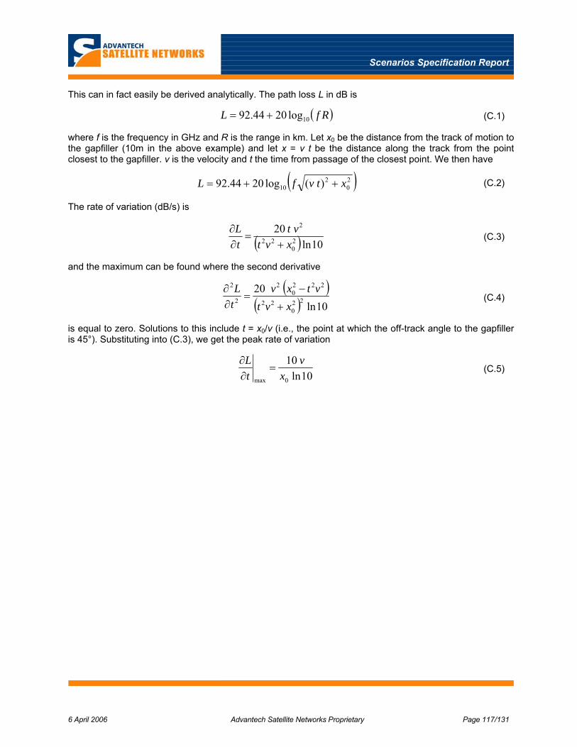
Scenarios Specification Report
6 April 2006 Advantech Satellite Networks Proprietary Page 117/131
This can in fact easily be derived analytically. The path loss L in dB is
( )RfL 10log2044.92 += (C.1)
where f is the frequency in GHz and R is the range in km. Let x0 be the distance from the track of motion to the gapfiller (10m in the above example) and let x = v t be the distance along the track from the point closest to the gapfiller. v is the velocity and t the time from passage of the closest point. We then have
( )20
210 )(log2044.92 xtvfL ++= (C.2)
The rate of variation (dB/s) is
( ) 10ln20
20
22
2
xvtvt
tL
+=
∂∂
(C.3)
and the maximum can be found where the second derivative
( )( ) 10ln20
220
22
2220
2
2
2
xvtvtxv
tL
+
−=
∂∂
(C.4)
is equal to zero. Solutions to this include t = x0/v (i.e., the point at which the off-track angle to the gapfiller is 45°). Substituting into (C.3), we get the peak rate of variation
10ln10
0max xv
tL
=∂∂
(C.5)

Scenarios Specification Report
6 April 2006 Advantech Satellite Networks Proprietary Page 122/131
18 APPENDIX E: AERONAUTICAL BROADBAND SYSTEMS
Given the strict limitations on off-axis power flux density emission and the limitation on satellite power flux density radiation (together with the need to minimise sensitivity to other system interference) brought to the proposal to use CDMA techniques as access scheme in both Skylink and Connexion.
Skylink uses the so-called PCMA (Paired Carrier Multiple Access) techniques to use a single transponder (and frequency band) for both the Forward (from the Gateway Station to the aircraft) and Reverse (from aircraft to GW) links (see Figure 18-1).
The carrier pairing strategy is possible because of the different G/T of the GWs and aircraft terminals. This difference results in a requirement of a much more powerful signal be transmitted by the satellite for the forward link than for the return link. Interference produced by the RL carriers on the FL carriers is thus negligible because this interference is below the thermal noise floor at the aircraft terminals.
FL Carrier
RL Carriers
Frequency
Pow
er D
ensi
ty S
pect
rum
FIGURE 18-1: GENERAL CARRIER-PAIRING CONFIGURATION
In Skylink, DSSS (Direct-Sequence Spread Spectrum) is used for both forward and return link. with a single forward link carrier occupying a full transponder (27 MHz typically) and return link carriers that are using a Spread Aloha access, occupying one or the other of the two 13 MHz half transponder available. Using a single frequency slot occupying the full transponder is also possible in the return link. A combination of open and closed loop power control is used to maximise capacity on the return link while complying with aggregate EIRP regulation limits.
The gateways — which have to decode the return link signals — cancel their own transmitted signal from the received signal. This is in principle an easy operation (Figure 18-2), thanks to the knowledge of the interfering signal; its effectiveness is well demonstrated by a number of operational VSAT systems using such an approach in the US.
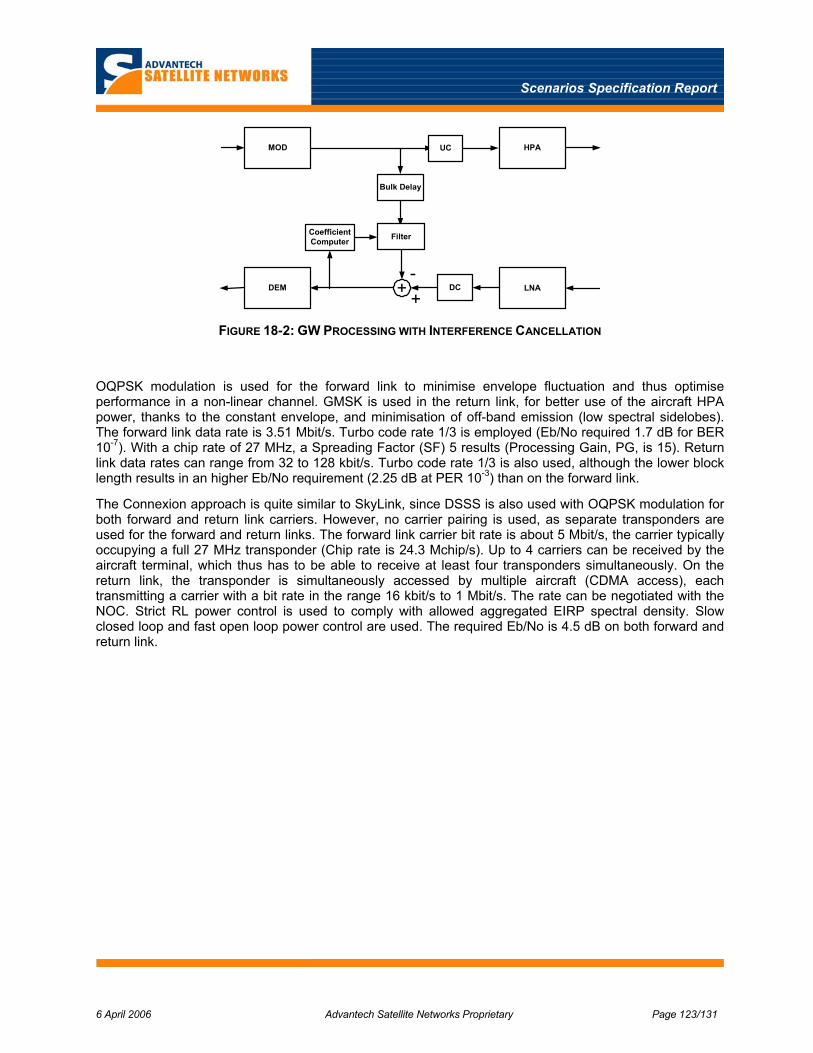
Scenarios Specification Report
6 April 2006 Advantech Satellite Networks Proprietary Page 123/131
MOD UC HPA
DEM DC LNA
Bulk Delay
+ +-
FilterCoefficientComputer
FIGURE 18-2: GW PROCESSING WITH INTERFERENCE CANCELLATION
OQPSK modulation is used for the forward link to minimise envelope fluctuation and thus optimise performance in a non-linear channel. GMSK is used in the return link, for better use of the aircraft HPA power, thanks to the constant envelope, and minimisation of off-band emission (low spectral sidelobes). The forward link data rate is 3.51 Mbit/s. Turbo code rate 1/3 is employed (Eb/No required 1.7 dB for BER 10-7). With a chip rate of 27 MHz, a Spreading Factor (SF) 5 results (Processing Gain, PG, is 15). Return link data rates can range from 32 to 128 kbit/s. Turbo code rate 1/3 is also used, although the lower block length results in an higher Eb/No requirement (2.25 dB at PER 10-3) than on the forward link.
The Connexion approach is quite similar to SkyLink, since DSSS is also used with OQPSK modulation for both forward and return link carriers. However, no carrier pairing is used, as separate transponders are used for the forward and return links. The forward link carrier bit rate is about 5 Mbit/s, the carrier typically occupying a full 27 MHz transponder (Chip rate is 24.3 Mchip/s). Up to 4 carriers can be received by the aircraft terminal, which thus has to be able to receive at least four transponders simultaneously. On the return link, the transponder is simultaneously accessed by multiple aircraft (CDMA access), each transmitting a carrier with a bit rate in the range 16 kbit/s to 1 Mbit/s. The rate can be negotiated with the NOC. Strict RL power control is used to comply with allowed aggregated EIRP spectral density. Slow closed loop and fast open loop power control are used. The required Eb/No is 4.5 dB on both forward and return link.

Scenarios Specification Report
6 April 2006 Advantech Satellite Networks Proprietary Page 124/131
19 APPENDIX F: INITIAL SPREAD SPECTRUM SYSTEM
This appendix provides a summary of the spread spectrum system designed by Advantech Satellite Networks in a previous study. This system is mainly targetted to line-of-sight systems; its primary purpose is to provide protection against adjacent-channel interference in the forward link and to allow compliance with regulatory constraints in the return link. It is not inherently designed to provide multiple-access capabilities or protection against multipath propagation.
The assessment of spreading alternatives concluded that direct sequence spreading is suitable for both return and forward path transmissions. The following sub-sections summarise the findings and the resulting air interface.
19.1 Forward Link
Several criteria are important in the selection of spreading alternatives and the details of the selected approach. These are:
• The fact spreading is required for DVB-S in the baseline, however this can also be applied to DVB-S2 with reduced spreading factors
• The spreading and dispreading shall not introduce unacceptable degradations to the data traffic
• Appropriate filtering of the spreading sequence is required
• All Hubs shall use the same spreading sequence
• Spreading shall be such that it does not unduly increase demodulator acquisition times
• Compatibility with the existing DVB-RCS system and air Interface should be maximised
• Spreading and de-spreading implementations shall be as simple as possible within the constraints of the requirements. In particular, the use of standard components shall be facilitated.
A trade-off was made based on these criteria, resulting in the methods and conceptual equipment architectures described in the sequel.
Equipment architecture for the Hub is relatively straightforward and is illustrated in Figure 19-1. The spreading sequence that is suggested is an m-sequence of length 511 with generator polynomial 1021 (octal).
The acquisition and de-spreading equipment for the terminal is slightly more complex. Based on the trades-off, the use of an incoherent delay locked loop was recommended. The basic structure of an analogue version of such a loop is illustrated in [F1]. However, a digital version is required to provide the flexibility that variable data and spreading rates require. A suitable digital design is shown in Figure 19-2.

Scenarios Specification Report
6 April 2006 Advantech Satellite Networks Proprietary Page 125/131
PulseShaping
Filter
PulseShaping
Filter
Conventional Modulator
SequenceGenerator
PulseShaping
Filter
PulseShaping
Filter
BalancedModulatorand Up-converter
IF Signal
I
Q
FIGURE 19-1: CONCEPTUAL BLOCK DIAGRAM OF FORWARD SPREAD-SPECTRUM MODULATOR.
Tuner +
Code Generator VCO
DataFilter
To Demodulator(Tuner)
Spread SignalInput Energy
Estimate+
+
+
+
A/D
EnergyEstimate
EnergyEstimate
EnergyEstimate
Accumulator
Microprocessor
D/A
2Connections
Bypass Switch
LPF
LPF
FIGURE 19-2: DIGITAL DELAY-LOCK LOOP AND DESPREADING
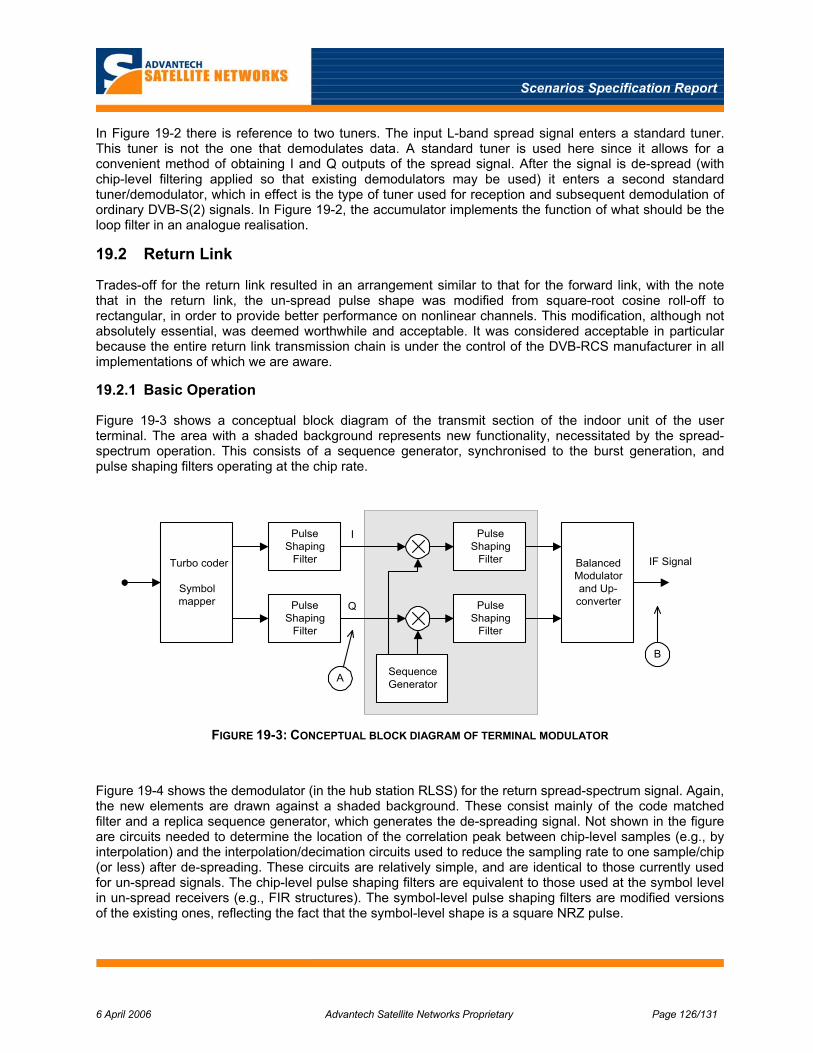
Scenarios Specification Report
6 April 2006 Advantech Satellite Networks Proprietary Page 126/131
In Figure 19-2 there is reference to two tuners. The input L-band spread signal enters a standard tuner. This tuner is not the one that demodulates data. A standard tuner is used here since it allows for a convenient method of obtaining I and Q outputs of the spread signal. After the signal is de-spread (with chip-level filtering applied so that existing demodulators may be used) it enters a second standard tuner/demodulator, which in effect is the type of tuner used for reception and subsequent demodulation of ordinary DVB-S(2) signals. In Figure 19-2, the accumulator implements the function of what should be the loop filter in an analogue realisation.
19.2 Return Link
Trades-off for the return link resulted in an arrangement similar to that for the forward link, with the note that in the return link, the un-spread pulse shape was modified from square-root cosine roll-off to rectangular, in order to provide better performance on nonlinear channels. This modification, although not absolutely essential, was deemed worthwhile and acceptable. It was considered acceptable in particular because the entire return link transmission chain is under the control of the DVB-RCS manufacturer in all implementations of which we are aware.
19.2.1 Basic Operation
Figure 19-3 shows a conceptual block diagram of the transmit section of the indoor unit of the user terminal. The area with a shaded background represents new functionality, necessitated by the spread-spectrum operation. This consists of a sequence generator, synchronised to the burst generation, and pulse shaping filters operating at the chip rate.
PulseShaping
Filter
PulseShaping
Filter
SequenceGenerator
PulseShaping
Filter
PulseShaping
Filter
BalancedModulatorand Up-converter
IF Signal
I
Q
Turbo coder
Symbolmapper
A
B
FIGURE 19-3: CONCEPTUAL BLOCK DIAGRAM OF TERMINAL MODULATOR
Figure 19-4 shows the demodulator (in the hub station RLSS) for the return spread-spectrum signal. Again, the new elements are drawn against a shaded background. These consist mainly of the code matched filter and a replica sequence generator, which generates the de-spreading signal. Not shown in the figure are circuits needed to determine the location of the correlation peak between chip-level samples (e.g., by interpolation) and the interpolation/decimation circuits used to reduce the sampling rate to one sample/chip (or less) after de-spreading. These circuits are relatively simple, and are identical to those currently used for un-spread signals. The chip-level pulse shaping filters are equivalent to those used at the symbol level in un-spread receivers (e.g., FIR structures). The symbol-level pulse shaping filters are modified versions of the existing ones, reflecting the fact that the symbol-level shape is a square NRZ pulse.
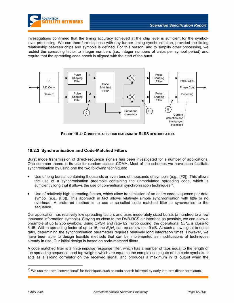
Scenarios Specification Report
6 April 2006 Advantech Satellite Networks Proprietary Page 127/131
Investigations confirmed that the timing accuracy achieved at the chip level is sufficient for the symbol-level processing. We can therefore dispense with any further timing synchronisation, provided the timing relationship between chips and symbols is defined. For this reason, and to simplify other processing, we restrict the spreading factor to integer numbers (i.e., integer numbers of chips per symbol period) and require that the spreading code epoch is aligned with the start of the burst.
PulseShaping
Filter
PulseShaping
Filter
I
Q
IF
A/D Conv.
De-mux.
CodeMatched
Filter
SequenceGenerator
PulseShaping
Filter
PulseShaping
Filter
Freq. Corr.
Phase Corr.
Decoding
C D E
Currentdetection and
timing syncbypassed
FIGURE 19-4: CONCEPTUAL BLOCK DIAGRAM OF RLSS DEMODULATOR.
19.2.2 Synchronisation and Code-Matched Filters
Burst mode transmission of direct-sequence signals has been investigated for a number of applications. One common theme is its use for random-access CDMA. Most of the schemes we have seen facilitate synchronisation by using one the two following techniques:
• Use of long bursts, containing thousands or even tens of thousands of symbols (e.g., [F2]). This allows the use of a synchronisation preamble containing the unmodulated spreading code, which is sufficiently long that it allows the use of conventional synchronisation techniques10.
• Use of relatively high spreading factors, which allow transmission of an entire code sequence per data symbol (e.g., [F3]). This approach in fact allows relatively simple synchronisation with little or no overhead. A preferred method is to use a so-called code matched filter to synchronise to the sequence.
Our application has relatively low spreading factors and uses moderately sized bursts (a hundred to a few thousand information symbols). Staying as close to the DVB-RCS air interface as possible, we can allow a preamble of up to 255 symbols. Using QPSK and rate-1/2 Turbo coding, the operational Es/N0 is close to 3 dB. With a spreading factor of up to 16, the Ec/N0 can be as low as –9 dB. At such a low signal-to-noise ratio, determining the synchronisation parameters requires relatively long integration times. However, we have been able to design feasible methods that can be implemented as modifications of techniques already in use. Our initial design is based on code-matched filters.
A code matched filter is a finite impulse response filter, which has a number of taps equal to the length of the spreading sequence, and tap weights which are equal to the complex conjugate of the code symbols. It acts as a sliding correlator on the received signal, and produces a maximum in its output when the
10 We use the term “conventional” for techniques such as code search followed by early-late or τ-dither correlators.

Scenarios Specification Report
6 April 2006 Advantech Satellite Networks Proprietary Page 128/131
spreading code is aligned with the replica contained in the filter taps. This filter operates on an “unmodulated” sequence; i.e., for best performance, it needs to know the exact sequence of code symbols (chips) transmitted.
The code matched filter is shown in Figure 19-5. It is in principle equivalent to the soft correlator used for burst synchronisation in Advantech Satellite Networks’ current demodulator. The main difference is that, given the low Ec/N0, it needs to be much longer (in terms of number of taps) than that used for un-spread signals. Complexity constraints limit the feasible number of taps to several hundred, if the code matched filter is to be implemented on the current demodulator platform. It was shown in the initial study that this is sufficient for the application in hand.
The performance of such correlators degrades rapidly in the presence of carrier frequency offsets. Since the frequency uncertainty is expressed in terms of symbol rates in our system, the frequency uncertainty for a given symbol rate decreases with increasing spreading factor when expressed in chip rates. On the other hand, the Ec/N0 is lower for larger spreading factors, so a longer chip sequence is necessary. These two effects counteract. As a result, operation with modest frequency offsets is feasible for all situations in our intended application.
Finally, we note that arbitrarily large frequency offsets can be accommodated at a cost that is linear in complexity. This is achieved by using multiple, parallel filters. These each have taps (sequence replicas) which are pre-compensated for an integer multiple of the range ∆fmax that can be handled by an individual correlator. Together, N such parallel correlators can detect signals in a contiguous frequency range of N∆fmax.
D
cn-1
D
cn-2 cn-3
D
c1 c0
...
...
...
FIGURE 19-5: CODE MATCHED FILTER CORRELATOR.
19.2.3 Choice of Spreading Sequence
The main purpose of the spreading is to distribute the signal energy evenly in the frequency domain. For this purpose, the sequence should have good autocorrelation properties (the autocorrelation is the Fourier transform of the power spectrum). If the sequence is shorter than the burst, the interesting property is the so-called “periodic” autocorrelation — i.e., the autocorrelation of an infinite repetition of the sequence.
For the preamble, the most interesting property is the so-called “aperiodic” autocorrelation; that is, the autocorrelation of a single instance of the sequence, preceded and followed by a signal with zero amplitude (in practice, by a random signal). The main reason for considering the detailed sequence properties for the preamble is the desire to avoid high sidelobe levels in the autocorrelation function; these can cause false alarms.

Scenarios Specification Report
6 April 2006 Advantech Satellite Networks Proprietary Page 129/131
For simplicity of implementation, it is attractive if the same sequence is used to both generate the preamble and to spread the data. We are therefore looking for sequences that have good properties both in terms of their periodic and aperiodic autocorrelation.
Golay proposed a merit factor for comparing sequence autocorrelation properties [F5]. This is essentially a measure of the “power” in the correlation sidelobes, and is defined as
∑−
=
= 1
2
2
2
2)( N
kka
NsMF (F.1)
for a sequence s of length N. This merit factor is arranged such that it is around 1 for a random sequence. The higher the merit factor, the better the sidelobe properties. We will use this to compare sequences. We have investigated three families of sequences:
PN sequences: These familiar sequences have extremely good periodic autocorrelation, but only moderately good aperiodic autocorrelation. They can be generated using linear feedback shift registers. One drawback of PN sequences is that they exist only in lengths of 2N–1.
ARM sequences: These sequences [F6] are very easy to generate; unlike PN sequences, the generator does not require feedback. Appendix A gives examples and also provides a detailed comparison between PN and ARM sequences. One drawback of ARM sequences is that they exist only in lengths of 2N.
N/4 rotated Legendre sequences: Legendre sequences exist for all lengths N, where N is prime. The sequence is defined in terms of the indices where “ones” are located. These are a subset Ω of the indices 0...N–1; i.e., sk = 1 when k ∈ Ω and 0 otherwise. Ω is defined as
⎭⎬⎫
⎩⎨⎧ −
−==Ω 1
21,...,0|mod2 NiNiα (F.2)
where α is a primitive root of 1 in GF(N). There is only one Legendre sequence for any prime N. Basic Legendre sequences have very poor aperiodic autocorrelation. However, a version of a Legendre sequence which has been rotated by 1/4 of its length (i.e., the first ⎣N/4⎦ symbols are moved to the end of the sequence) turn out to have extremely good aperiodic autocorrelation [F7]. It follows from the extensions made in [F7] that we should also expect reasonable periodic autocorrelation for the rotated Legendre sequences.
Investigations based on the Golay merit factor led us to choose the N/4 rotated Legendre sequences, because of their good properties in terms of both type of autocorrelation.
19.3 Air Interface Summary
This sub-section summarises the air interface resulting from the design activities described above.
19.3.1 Forward Link
The forward link transmissions shall comply with the provisions of [F8], with restrictions and exceptions as defined in the present document.
The forward link transmission can be based on DVB-S [F9] or DVB-S2 [F10].
The transmission can optionally employ spectrum spreading as defined in the present document. When spectrum spreading is not employed, the transmitted signal shall conform to the provisions of [F9] or [F10] as applicable.
Scenarios Specification Report
6 April 2006 Advantech Satellite Networks Proprietary Page 130/131
When spectrum spreading is employed, the transmitted signal shall be equivalent to one obtained in the following manner and as illustrated in Figure 19-1.
• Spreading factors shall be integer values between 1 and 5.
• DVB-S or DVB-S2 transmissions shall be spread.
• Up to and including the baseband pulse shaping, the signal shall be generated in accordance with the applicable standard.
• The in-phase and quadrature components of the baseband modulating waveform (i.e., including the pulse shaping at symbol level) shall each be multiplied by an impulse train containing weighted impulses at a rate of one impulse per spreading chip.
• The chip impulse train shall be provided by a sequence generator. The impulse weight of the chip waveform shall be +1 when the sequence generator outputs a logical “1” and shall be –1 when the sequence generator outputs a logical “0”.
• The sequence generator shall be an m-sequence of length 511, with generator polynomial 1021 (octal).
• The chip rate shall be an integer multiple of the symbol rate and shall be at least twice the symbol rate and shall possess the same stability as the symbol rate. Other than this, the timing relationship between the signal structure and the sequence is not defined. In particular, the epoch of the spreading sequence is not related to any element of the un-spread signal.
• Prior to modulation, the I and Q signals (mathematically represented by a succession of Dirac delta functions, multiplied by the amplitudes I and Q, spaced by the chip duration Tc = 1/Rc) shall be modulated by a spreading signal with square root raised cosine filtered. The roll-off factor shall be 35 %. The use of signal spreading shall not degrade the BER performance of the forward link traffic by more than 0.1 dB.
• It shall take no longer than 1 second for the receiver to acquire the spreading sequence.
19.3.2 Return Link
The return link transmissions shall comply with the provisions of [F8], with restrictions and exceptions as defined in the following.
The transmission can optionally employ spectrum spreading as defined in the present document. When spectrum spreading is not employed, the transmitted signal shall conform to the provisions of [F8].
When spectrum spreading is employed, the transmitted signal shall be equivalent to one obtained in the following manner and as illustrated in Figure 19-3.
• Up to the baseband pulse shaping, the signal shall be generated in accordance with [F8].
• The baseband pulse shaping for each of the in-phase and quadrature components shall be a bi-polar, real, rectangular NRZ pulse with a duration of one symbol period.
• The in-phase and quadrature components of the baseband modulating waveform (i.e., including the pulse shaping at symbol level) shall each be multiplied by an impulse train containing weighted impulses at a rate of one impulse per spreading chip.
• The chip impulse train shall be provided by a sequence generator. The impulse weight of the chip waveform shall be +1 when the sequence generator outputs a logical “1” and shall be –1 when the sequence generator outputs a logical “0”.

Scenarios Specification Report
6 April 2006 Advantech Satellite Networks Proprietary Page 131/131
• The spreading sequence shall be a Legendre sequence of length N, in which the first ⎣N/4⎦ symbols are moved to the end of the sequence. The sequence shall be re-started at the beginning of each transmitted burst and shall be repeated until the end of each burst.
• The preamble symbols, as defined in the timeslot composition table, shall all be set to logical “11”.
• The length of the preamble sequence, as defined in the timeslot composition table, shall be the smallest number of symbols that allow a complete period of the spreading sequence to be transmitted during the preamble.
• The chip rate shall be an integer multiple of the symbol rate.
• The spreading sequence shall be applied to all symbols in the burst and shall be synchronised to the burst as follows: For a spreading factor (ratio of chip rate to symbol rate) of S, the first S chips of the spreading sequence shall be applied in the interval corresponding to the first symbol of the burst preamble.
• The output of the spreading process shall be filtered to a spectral shape in accordance with [F8], with the proviso that references to symbol rates shall be interpreted as the chip rate.
19.4 References
[F1] J.J. Spilker, Jr., “Digital Communications by Satellite”, Prentice-Hall, 1977.
[F2] C.K.H. Deng, “A Burst Mode PN Acquisition Processor for Direct Sequence Spread-Spectrum”, UCLA Master’s Thesis, 1998.
[F3] D.E. Gossing, “Rapid Robust Acquisition for Burst-Mode Spread Spectrum”, U. South Australia Ph.D. Thesis, 1997.
[F4] M.R. Soleymani and H. Girard, “The Effect of the Frequency Offset on the Probability of Miss in a Packet Modem Using CFAR Detection Method”, IEEE Transactions on Communications, Vol. 40, No. 7, pp. 1205-1211, July 1992.
[F5] M.J.E. Golay, “Sieves for Low Autocorrelation Binary Sequences”, IEEE Trans. Inf. Theory, vol. 23, no. 1, pp.43–51, Jan. 1977.
[F6] Samsung Electronic co. Ltd, “Preamble Structure for Synchronization”, Contribution 134r0 to IEEE 802.15, 3 March, 2003.
[F7] R.A. Kristiansen, M.G. Parker, “Binary Sequences with Asymptotic merit factor > 6.3”, IEEE Trans. Inform. Theory, 50:3385–3389, 2004
[F8] ETSI EN 301 790: Digital Video Broadcasting (DVB); Interaction channel for satellite distribution systems
[F9] ETSI EN 300 421 v1.1.2 (1997-08), "Digital Video Broadcasting (DVB); Framing Structure, Channel Coding and Modulation for 11/12 GHz Satellite Services”
[F10] ETSI EN 302 307, "Digital Video Broadcasting (DVB); Second Generation Framing Structure, Channel Coding and Modulation Systems for Broadcasting, Interactive Services, News Gathering and Other Broadband Satellite Applications”