Scenario-Based Requirement Analysis · usage. A modelling language ... illustrated with a case...
30
1 Scenario-Based Requirement Analysis 1 Alistair Sutcliffe Centre for HCI Design School of Informatics City University Northampton Square London EC1V 0HB, UK Tel: +44-171-477-8411 e-mail: [email protected] Abstract A method for scenario based requirements engineering is described. The method uses two types of scenario, structure models of the system context and scripts of system usage. A modelling language is reported for describing scenarios, and heuristics are given to cross check dependencies between scenario models and the requirements specification. Heuristics are grouped into several analytic treatments that investigate correspondences between users’ goals and system functions; input events and system processes to deal with them; system output and its destination in the scenario model, and acceptability analysis of system output for different stakeholders. The method is illustrated with a case study taken from the London Ambulance Service report. The prospects for scenario based RE and related work are discussed. 1. Introduction In spite of the increasing attention that scenarios have attracted in requirements engineering [1], few methods have merged to guide the practice of scenario based requirements analysis or validation. Several different interpretations have appeared ranging from scenarios as a basis for generating user cases [2], descriptions of system usage to help understand socio-technical system implications [3], and experience based narratives for requirements elicitation and validation [4], [5]. However, few authors give advice on how to use scenarios in the process of analysis and validation. One of the exceptions is the Inquiry Cycle of Potts [4] which describes scenario scripts of system use with a method for goal-oriented requirements analysis. Dependencies between the events originating in the scenario are validated against the requirements specification, and the requirements are elaborated to deal with obstacles or problems that prevent successful system operation. Unfortunately, the Inquiry Cycle does not give detailed advice about how scenarios are used to generate questions; furthermore it leaves open to human judgement how dependencies between system output and users are determined. Nevertheless, the Inquiry Cycle has demonstrated its utility in industrial scale case studies [6]. 1 This research has been partially funded by the European Commission ESPRIT 21903 ’CREWS’ (Co- operative Requirements Engineering With Scenarios) long-term research project.
Transcript of Scenario-Based Requirement Analysis · usage. A modelling language ... illustrated with a case...

1
Scenario-Based Requirement Analysis1
Alistair Sutcliffe
Centre for HCI DesignSchool of Informatics
City UniversityNorthampton Square
London EC1V 0HB, UKTel: +44-171-477-8411
e-mail: [email protected]
Abstract
A method for scenario based requirements engineering is described. The method usestwo types of scenario, structure models of the system context and scripts of systemusage. A modelling language is reported for describing scenarios, and heuristics aregiven to cross check dependencies between scenario models and the requirementsspecification. Heuristics are grouped into several analytic treatments that investigatecorrespondences between users’ goals and system functions; input events and systemprocesses to deal with them; system output and its destination in the scenario model,and acceptability analysis of system output for different stakeholders. The method isillustrated with a case study taken from the London Ambulance Service report. Theprospects for scenario based RE and related work are discussed.
1. Introduction
In spite of the increasing attention that scenarios have attracted in requirementsengineering [1], few methods have merged to guide the practice of scenario basedrequirements analysis or validation. Several different interpretations have appearedranging from scenarios as a basis for generating user cases [2], descriptions of systemusage to help understand socio-technical system implications [3], and experience basednarratives for requirements elicitation and validation [4], [5]. However, few authorsgive advice on how to use scenarios in the process of analysis and validation. One ofthe exceptions is the Inquiry Cycle of Potts [4] which describes scenario scripts ofsystem use with a method for goal-oriented requirements analysis. Dependenciesbetween the events originating in the scenario are validated against the requirementsspecification, and the requirements are elaborated to deal with obstacles or problemsthat prevent successful system operation. Unfortunately, the Inquiry Cycle does notgive detailed advice about how scenarios are used to generate questions; furthermore itleaves open to human judgement how dependencies between system output and usersare determined. Nevertheless, the Inquiry Cycle has demonstrated its utility inindustrial scale case studies [6].
1 This research has been partially funded by the European Commission ESPRIT 21903 ’CREWS’ (Co-operative Requirements Engineering With Scenarios) long-term research project.
2
This paper builds on the concepts of the Inquiry Cycle with the aim of providing moredetailed advice about how scenarios can be used in requirements analysis andvalidation. In our previous work we proposed a scenario based requirements analysismethod (SCRAM) that recommended a combination of concept demonstrators,scenarios and design rationale [7], [5]. Scenarios described typical user tasks andconcept demonstrators portrayed an early design vision of the required system.SCRAM, however, gave only outline guidance for a scenario-based analysis.
Scenarios have been used with many different connotations. One important distinctionis between scenarios that form part of the specification of the required system, or arederived from it, versus scenarios that are captured from actual experience and do notoriginate from a system design. The former view has been adopted in user cases in theobject oriented literature [2, 8, 9], in which a use case embodies a projected vision ofuser interaction with the designed system. Scenarios are threads of interaction whichmay occur through the network of a user case that describes several pathways in user-system interaction. Scenarios of this type have several precedents, for instance,viewpoints in CORE [10] described interaction between an intended system andexternal agents, as did context diagrams in structured systems analysis [11]. We usescenarios in the second sense, as descriptions taken from reality before a system isimplemented, and used to validate the required system. This concords with scenarioscripts as advocated by the Inquiry cycle [4].
Validating requirements by focusing on dependencies between the intended system andits immediate environment has been researched by Jackson [12] who points out thatdomains impose obligations on a required system. Jackson formalises eventdependencies between the system and its environment that are inherent in the laws ofphysics, e.g. obligations for a required system in avionics and other real timeapplications, and events that may arise from human failure, but the causality of suchfailure is not explicitly analysed and the obligations of systems to users are notaddressed. Modelling relationships and dependencies between people and systems hasbeen investigated by Mylopoulos et al [13] and Chung [14]. Their i* framework iscomposed of strategic dependency and strategic rationale enterprise models whichfacilitate investigation relationships between requirements goals, agents and tasks. Themodels make no judgement about the system boundary; instead, the framework isapplied to a socio-technical system. Although scenarios do not appear in the i*framework, enterprise models may be derived from scenarios of the intended systemenvironment. This research and others in the enterprise modelling tradition [15], [16]suggest some approaches for validating requirements at the social level, but no detailedguidance is given so the practitioner is left with the problem of extracting generallessons from examples. In conclusion methods are required to unlock the potential ofscenario based RE; furthermore, the relationship between investigation based onexamples and models need to be understood more clearly. With this motivation in mindthis paper reports on development of the second generation SCRAM method thatintegrates scenarios with model based requirements analysis.
The paper is organised in three sections. First we introduce scenario basedrequirements analysis, a schema for representing scenario based knowledge and explainthe background to the case study of the London Ambulance service, a well knownsystem failure caused by poor Requirements Engineering (RE). Section 3 describes awalkthrough method for scenario based requirements validation that investigates both

3
inbound and outbound event dependencies. Each step is illustrated by the case study.Finally we discuss related work and future prospects for scenario based requirementsengineering.
2. Scenario Based Requirements Analysis
First it is necessary to define a knowledge representation schema for scenarios. This isa prerequisite for the walkthrough method that analyses the dependencies between thesystem components and their environment. Although we describe the dependencychecking in two separate sections, one for inbound and one for outbound events, inpractice analysis of both is interleaved.
For our purposes scenarios are defined as "facts describing an existing system and itsenvironment including the behaviour of agents and sufficient context information toallow discovery and validation of system requirements". Scenarios are instances ofactual experience with a system captured from users. Since agent’s behaviour is a keycomponent in scenarios, we adapt scripts proposed in the Inquiry Cycle [4], i.e. aninstant storyline of events describing system operation. To scripts we add further detailof the system environment so the context of activity can be evaluated. Scenario-basedmodels are created to describe the system environment which can then be investigatedfor connections and dependencies between the system and its environment. Scenariomodelling may appear to be similar to system modelling, indeed the content of asystem or environment model depends on where the boundary of the intended system isplaced. System boundaries will frequently change during a requirements investigation,hence we see a single model of the intended system-environment upon which aboundary will be eventually imposed. Furthermore, within the model alternativetechnical system specifications may be explored. When the boundary of the requiredsystem becomes fixed, use cases may be constructed to describe interaction betweenstakeholders and the system, facilitating the migration from requirements analysisdescribed in this paper to object oriented specifications. The method described in thispaper is intended to extend and complement the early phases of object orienteddevelopment following use case approach (e.g. UML, Rational 1997[17]. Therelationship between scenarios and the requirements specification is illustrated in figure1. Scenarios contain information about operation of the current system and itsenvironment. While scenarios are usually examples of interaction at the instance level,e.g. "Jane filled in the order form and pressed the enter key to send it to the database",they may also contain contextual information about the system environment, e.g. " Janeworked in a busy office, she was frequently interrupted which made concentrating onorder entry difficult". Scenarios may contain descriptions of activities in manualsystems, interaction with legacy systems, descriptions of agents, roles, and theirorganisation settings. The requirements specification is an artefact that emerges duringthe RE process evolving from simple lists of functional desiderata to models thatconstitute a requirements specification. The method described in this paper usesscenarios as test data and validates requirements by investigating the dependenciesbetween events that originate in the environment (i.e. described in the scenario), onrequirements specification and system error. In the latter case scenarios are usedprojector stories of system use.

4
Scenarios are captured as text narratives, sketches and informal media. As analysisprogresses informal representations may be replaced by models. The first question ishow far should the modelling endeavour be extended from the system core outwardsinto the social domain? Ultimately the whole of society could be modelled, buteconomics dictate that modelling be restricted to the essential set of facts that are usefulin shaping the new system. Modelling is limited by time and available resources,however, the methods indicates the extent of modelling by describing facts about thesystem environment that should be captured for requirements validation. The secondquestion is what sort of facts should be captured for modelling? To address this point ascenario-based modelling language is proposed to support understanding of newapplication domains. Finally scenarios contain instance information as they describereal world events that happen to individuals. This raises the problem of how instantlevel information is related to types and classes and how much instant information isexplicitly modelled in scenarios, rather than leaving it as an example based narrativedescription.
ScenariosRequirements specification
system output impacts on the social domain
inbound events imply process requirements
examples, and instance level descriptions of system usage in a context
user agents, usage scripts
Figure 1 Scenarios and models of the required system and its environment
The method stages that use of scenarios in requirements discovery and validation isillustrated in figure 2. Two types of scenario are proposed: scenario scripts thatdescribe system usage; and scenario structure models containing facts about the systemenvironment. Structure models capture a broad view of the modelled domain to supportinvestigation of the relationship between a required system and its environment.Scripts on the other hand take a more detailed view of agents’ behaviour fordependency analysis.
The first part of the method analyses the user’s goals (1) and checks whether they aresupported by system functions. This creates a first cut requirements specificationwhich describes high level system processes. The requirements specification iselaborated by investigating dependencies between input events (2) described in thescenario script and requirements functions. This identifies requirements to deal withinbound events from users and the system environment of different types as well asanalysing unexpected events. Inbound events are described in scenarios of interactionbetween users and the proposed system. This analysis leads to 1st cut decisions aboutthe extent of the automation and user-system boundary as the requirementsspecification is updated to add functions to deal with different inbound events. System

5
outputs will be motivated by the users goals in step (1) and described in terms ofprocess and outline content in the requirements specification. This enablesacceptability and impact of system output on users to be assessed, first by specifyingthe output in more detail in step (3) and then analysing the requirements to supportusers tasks in step 4. This is followed by tracing the destination and use of output bydifferent stakeholders and investigating whether the system provides the necessarysupport for users’ work and does not make any unacceptable demands on them (socialimpact analysis in step 5). Finally a stakeholder cost benefit analysis is carried out tocomplete the prognosis of how people may react to the required system (step 6). Thescenario structure model is used to assess the impact of system output and couplingbetween the technical and social systems. Scenarios may be imaginary stories of use forthe new system, or based on real examples. Although the method implies a sequentialprocess in figure 2, in practice many of the stages will be interleaved as understandingabout the system and its environment increases during requirements analysis.Alternative versions of the requirements specification may be produced depending ondecisions on the extent of automation, and scenarios created to explained differentversions to users. The method is described in more detail in section 3, where the sub-sections maps methods to step in figure 2, before proceeding to the method it isnecessary to define the models used to represent the scenarios

6
Goal analysis
Inbound event analysis
Output requirements analysis
Social impact analysis
Scenario structure model
Scenario scripts
Characterise system output
Requirements specifciation
Requirements specifciation
Users1
2
4
5
6
aims, goals
examples problems
goal lists
input process requirements
usage scenarios
initial system model
system output types
information requirements
agents destinations
refined requirements
user, env. events
system model
Stakeholder analysis
3
Figure 2. Outline of method steps, showing input from scenarios to requirementsanalysis
2.1 Scenario knowledge representation schema
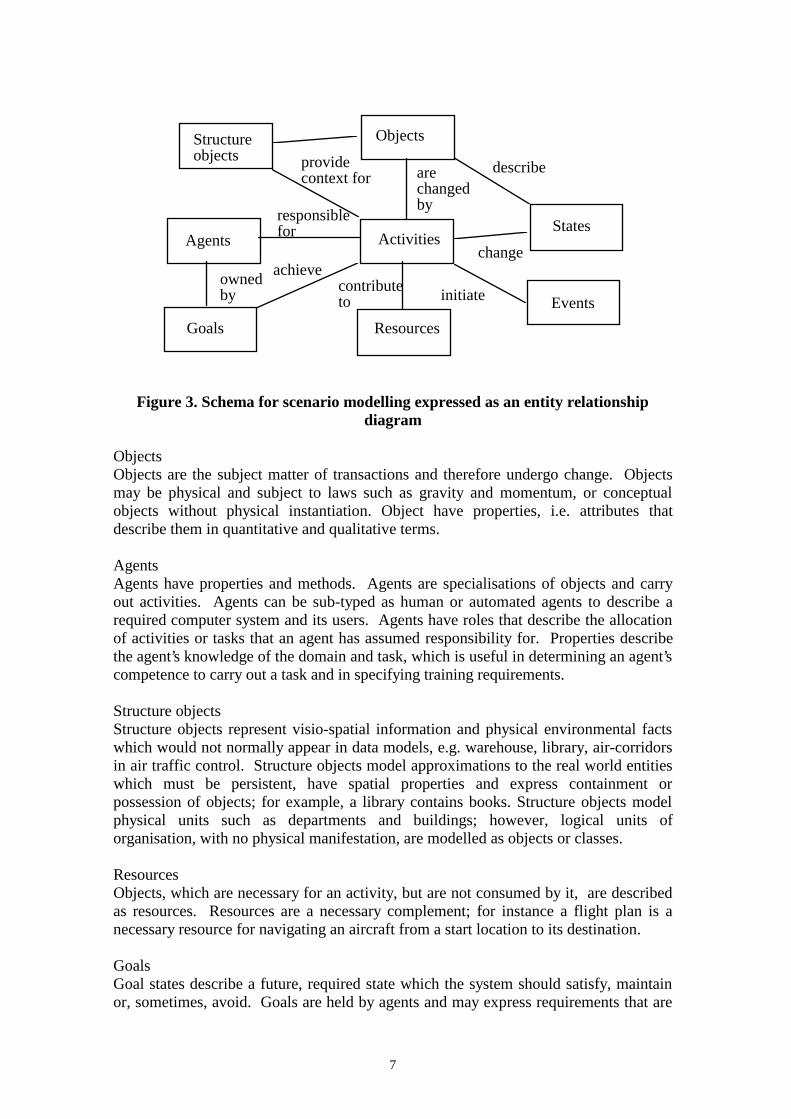
The schema components use semantics that are familiar from software engineeringspecifications which we have adapted from our previous research [18] for scenariomodelling. The schema is summarised in figure 3.
7
ObjectsStructure objects
Agents Activities
Goals Resources
achieve
Events
States
describeare changed by
provide context for
owned by
responsible for
contribute to
change
initiate
Figure 3. Schema for scenario modelling expressed as an entity relationshipdiagram
ObjectsObjects are the subject matter of transactions and therefore undergo change. Objectsmay be physical and subject to laws such as gravity and momentum, or conceptualobjects without physical instantiation. Object have properties, i.e. attributes thatdescribe them in quantitative and qualitative terms.
AgentsAgents have properties and methods. Agents are specialisations of objects and carryout activities. Agents can be sub-typed as human or automated agents to describe arequired computer system and its users. Agents have roles that describe the allocationof activities or tasks that an agent has assumed responsibility for. Properties describethe agent’s knowledge of the domain and task, which is useful in determining an agent’scompetence to carry out a task and in specifying training requirements.
Structure objectsStructure objects represent visio-spatial information and physical environmental factswhich would not normally appear in data models, e.g. warehouse, library, air-corridorsin air traffic control. Structure objects model approximations to the real world entitieswhich must be persistent, have spatial properties and express containment orpossession of objects; for example, a library contains books. Structure objects modelphysical units such as departments and buildings; however, logical units oforganisation, with no physical manifestation, are modelled as objects or classes.
ResourcesObjects, which are necessary for an activity, but are not consumed by it, are describedas resources. Resources are a necessary complement; for instance a flight plan is anecessary resource for navigating an aircraft from a start location to its destination.
GoalsGoal states describe a future, required state which the system should satisfy, maintainor, sometimes, avoid. Goals are held by agents and may express requirements that are
8
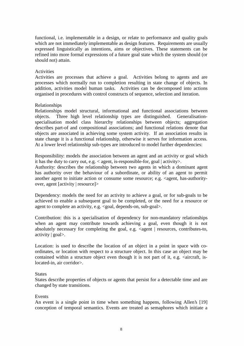
functional, i.e. implementable in a design, or relate to performance and quality goalswhich are not immediately implementable as design features. Requirements are usuallyexpressed linguistically as intentions, aims or objectives. These statements can berefined into more formal expressions of a future goal state which the system should (orshould not) attain.
ActivitiesActivities are processes that achieve a goal. Activities belong to agents and areprocesses which normally run to completion resulting in state change of objects. Inaddition, activities model human tasks. Activities can be decomposed into actionsorganised in procedures with control constructs of sequence, selection and iteration.
RelationshipsRelationships model structural, informational and functional associations betweenobjects. Three high level relationship types are distinguished. Generalisation-specialisation model class hierarchy relationships between objects; aggregationdescribes part-of and compositional associations; and functional relations denote thatobjects are associated in achieving some system activity. If an association results instate change it is a functional relationship, otherwise it serves for information access.At a lower level relationship sub-types are introduced to model further dependencies:
Responsibility: models the association between an agent and an activity or goal whichit has the duty to carry out, e.g. < agent, is-responsible-for, goal | activity>.Authority: describes the relationship between two agents in which a dominant agenthas authority over the behaviour of a subordinate, or ability of an agent to permitanother agent to initiate action or consume some resource; e.g. <agent, has-authority-over, agent [activity | resource]>
Dependency: models the need for an activity to achieve a goal, or for sub-goals to beachieved to enable a subsequent goal to be completed, or the need for a resource oragent to complete an activity, e.g. <goal, depends-on, sub-goal>.
Contribution: this is a specialisation of dependency for non-mandatory relationshipswhen an agent may contribute towards achieving a goal, even though it is notabsolutely necessary for completing the goal, e.g. <agent | resources, contributes-to,activity | goal>.
Location: is used to describe the location of an object in a point in space with co-ordinates, or location with respect to a structure object. In this case an object may becontained within a structure object even though it is not part of it, e.g. <aircraft, is-located-in, air corridor>.
StatesStates describe properties of objects or agents that persist for a detectable time and arechanged by state transitions.
EventsAn event is a single point in time when something happens, following Allen’s [19]conception of temporal semantics. Events are treated as semaphores which initiate a

9
state transition. For instance, the dispatch of goods from the warehouse to customer istriggered by a customer order (a request event).
This completes the knowledge representation schema. In the following section wedescribe how the schema is used for creating a scenario model. First a scenariostructure model is created using the schema to describe the major components in thedomain and their activity. Then more detailed descriptions of behaviour and interactionbetween agents are described and illustrated with user cases and event trace diagramsto integrate with standard OO approaches [17]. These detailed descriptions are referredto as scenario scripts and record the event sequences in real life examples of systemoperation. As scenario scripts are collected, more event trace diagrams will be addedto document the scenario. However, the structure model should remain reasonablyconstant, although it may need updating if a script introduces a new agent or activity.
2.2. Modelling scenarios
At this stage the case study of the London Ambulance Service, a well documentedfailure in requirements engineering and system design [20] is introduced. Theapplication is a complex, socio-technical system which has a documented requirementsspecification and material from which scenarios can be constructed. As spaceprecludes an exhaustive analysis of the whole system, we illustrate operation of themethod with selected elements of the system.
2.2.1 Case study description
The London Ambulance Service (LAS) Computer-Aided Dispatch System wasinitiated in 1991 as a new computer-aided ambulance dispatch system for London. Theintention was to replace a resource-intensive manual system with a computerised onethat would, in essence, enable one human controller to manage an entire incident fromcall-taking to the arrival of the ambulance at the incident scene. The implementation inOctober 1992 encountered many problems and operations reverted to the manualsystem one month later after a series of well-publicised catastrophic failures.
The London Ambulance Service is a large organisation. It had, in 1992, over 2700staff (operational staff, control assistants, managers, administrators, maintenance andancillary). It also had 305 accident and emergency ambulances, 445 patient transportservice ambulances, 2 emergency control vehicles, rapid response units and even 1helicopter. Much of its operations are real-time and mission critical, in that people candie if an ambulance does not arrive in time. It requires information about patients,emergencies, hospitals, road conditions, ambulance locations and calls to functioneffectively. The system is also both distributed and embedded, in that it relies on muchhardware to define the location of ambulances, communicate with ambulance crewsand so on. Indeed, the mobile nature of its operations in London make the system verycomplex and prone to problems.
The original system had evolved over a considerable amount of time. Ambulancecrews had considerable knowledge of London as well as emergency conditions, and thecontrol room staff worked as closely-knit teams in constant communication with each
10
other to dispatch the most appropriate ambulance to the right accident. The systemrelied on skilled individuals with extensive domain knowledge, including thegeography of London.
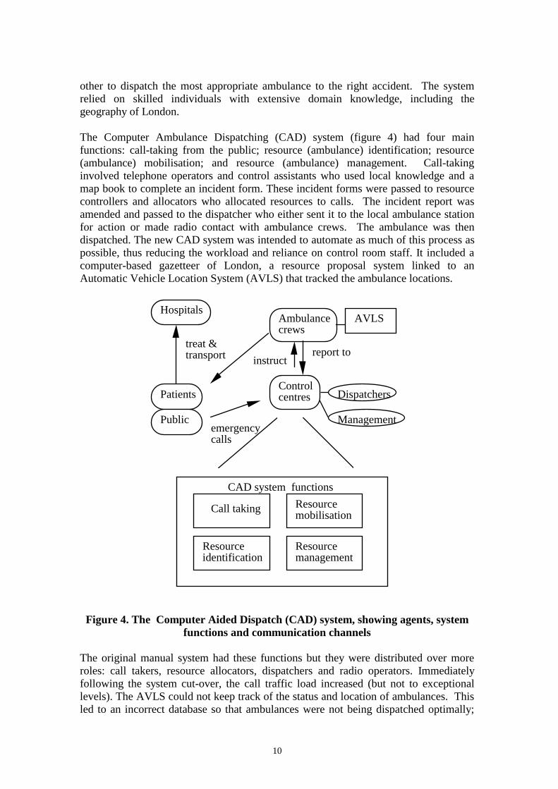
The Computer Ambulance Dispatching (CAD) system (figure 4) had four mainfunctions: call-taking from the public; resource (ambulance) identification; resource(ambulance) mobilisation; and resource (ambulance) management. Call-takinginvolved telephone operators and control assistants who used local knowledge and amap book to complete an incident form. These incident forms were passed to resourcecontrollers and allocators who allocated resources to calls. The incident report wasamended and passed to the dispatcher who either sent it to the local ambulance stationfor action or made radio contact with ambulance crews. The ambulance was thendispatched. The new CAD system was intended to automate as much of this process aspossible, thus reducing the workload and reliance on control room staff. It included acomputer-based gazetteer of London, a resource proposal system linked to anAutomatic Vehicle Location System (AVLS) that tracked the ambulance locations.
Call taking
Resource identification
Resource mobilisation
Resource management
Ambulance crews
Control centres
Hospitals
Dispatchers
Management
CAD system functions
AVLS
Patients
Publicemergency calls
treat & transport instruct
report to
Figure 4. The Computer Aided Dispatch (CAD) system, showing agents, systemfunctions and communication channels
The original manual system had these functions but they were distributed over moreroles: call takers, resource allocators, dispatchers and radio operators. Immediatelyfollowing the system cut-over, the call traffic load increased (but not to exceptionallevels). The AVLS could not keep track of the status and location of ambulances. Thisled to an incorrect database so that ambulances were not being dispatched optimally;

11
frequently, more than one ambulance was being assigned to one call. As a consequencethere were a large number of exception messages and the system slowed down as themessage queue grew. Unresponded exception messages generated repeat messages andthe message lists scrolled off the top of the screens so that important messages werelost from view. Ambulance crews were frustrated and, under pressure, were slow innotifying the status of the unit. They could not, or would not, use their Mobile DataTerminals (MDTs) and used incorrect sequences to enter the status information. Thepublic were repeating their calls because of the delay in response. The AVLS no longerknew which units were available and the resource proposal software was taking a longtime to perform its searches. As a result the entire system ground to a halt. It was takenoff-line and the LAS reverted to the manual dispatching system.
The scenario structure model for the system is illustrated in figure 5.
Answer call
Crews
Ambulance
London street space
Stabilise patient
Plan route
Navigate & drive
Treat patient
Get to accident
Transport patient to hospital
Public
Accident
Route
Route knowledge
are carried out in
subject matter of
carry out/ involved-in
fulfilled by
supported by
Goals
Agents
Activities
Objects
Resource
Structure object
Figure 5. A partial structure model for the Ambulance-crew sub-system. Eventsand states have been omitted
Note that the model contains information which is not explicitly stated in the scenariosuch as the responsibilities and goals of the crews.
2.2.2 Scenario scripts
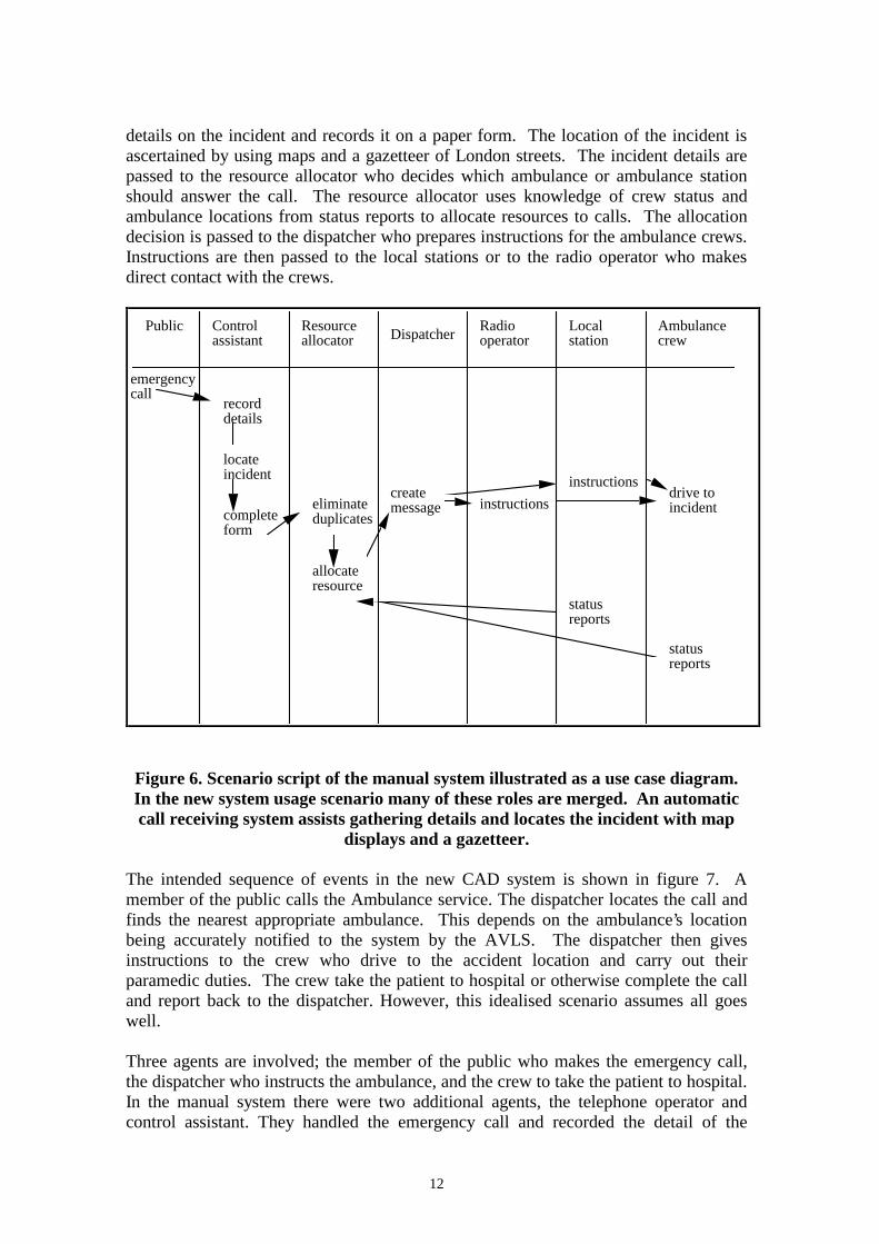
The user case scenario of the manual system is shown in figure 6. It commences witha member of the public placing a call that is received by a call operator who takes
12
details on the incident and records it on a paper form. The location of the incident isascertained by using maps and a gazetteer of London streets. The incident details arepassed to the resource allocator who decides which ambulance or ambulance stationshould answer the call. The resource allocator uses knowledge of crew status andambulance locations from status reports to allocate resources to calls. The allocationdecision is passed to the dispatcher who prepares instructions for the ambulance crews.Instructions are then passed to the local stations or to the radio operator who makesdirect contact with the crews.
Public Control assistant
Resource allocator Dispatcher
Radio operator
Ambulance crew
Local station
record details
emergency call
complete form
locate incident
eliminate duplicates
allocate resource
create message instructions
instructions
status reports
status reports
drive to incident
Figure 6. Scenario script of the manual system illustrated as a use case diagram.In the new system usage scenario many of these roles are merged. An automaticcall receiving system assists gathering details and locates the incident with map
displays and a gazetteer.
The intended sequence of events in the new CAD system is shown in figure 7. Amember of the public calls the Ambulance service. The dispatcher locates the call andfinds the nearest appropriate ambulance. This depends on the ambulance’s locationbeing accurately notified to the system by the AVLS. The dispatcher then givesinstructions to the crew who drive to the accident location and carry out theirparamedic duties. The crew take the patient to hospital or otherwise complete the calland report back to the dispatcher. However, this idealised scenario assumes all goeswell.
Three agents are involved; the member of the public who makes the emergency call,the dispatcher who instructs the ambulance, and the crew to take the patient to hospital.In the manual system there were two additional agents, the telephone operator andcontrol assistant. They handled the emergency call and recorded the detail of the

13
accident and its location. The new computer system was intended to simplify theprocess by eliminating this interface. As the dispatchers’ work would be increased thecomputer system has to provide effective decision support.
The scenario consists of two models: the structure model that describes the LASdomain, its agents and activities; and one or more behaviour models expressed as eventtraces.
Public Control assistant
Resource allocator Dispatcher
Radio operator
Ambulance crew
Local station
record details
emergency call
complete form
locate incident
eliminate duplicates
allocate resource
create message instructions
instructions
status reports
status reports
drive to incident
Figure 7. Scenario script for the LAS, covering crew and dispatcher sub-systems,illustrated as a use case-event trace diagram. The approximate sequence of events
reads from top to bottom.
3. Scenario-Requirements Validation
The essence of the method is to compare scenarios with a developing requirementsspecification. The method makes no recommendation about the format of therequirements specification. This may be a formal language, a list of requirementsgoals, or an artefact such as prototypes or storyboards. From preliminary fact gatheringinitial scenarios and models are created. A decision is taken on first cut partitioning ofthe model into the intended system and its environment. Alternative partitionings andsystem designs may be created and followed through the method stages. Differentboundaries and automation decisions may also be regarded as scenarios for the future

14
system and user case techniques may be employed to represent them. The number ofalternatives that can be explored depends on resource constraints. The environmentbecomes the usage scenario which is cross checked against the system. Analysis willstimulate further fact gathering as understanding of the domain increases. This, in turn,will lead to more elaborate models of the system and its environment which can bechecked more thoroughly. The method proceeds by iterative cycles of fact gathering,modelling and requirements elaboration/validation.
In the following section the walkthrough method and question templates are describedthat guide the analyst when checking the requirements specification against thescenario and vice versa.
3.1 Goal analysis
Goals in the scenario structure model are compared with the requirementsspecification. Using the following heuristics each user goal in the scenario is crosschecked with functional goals with the requirements specification.
• Does the user’s goal require computerised support? If so then a functionalrequirement should be added to the requirements specification; otherwiseimplications for non- functional requirements should be considered.
• Does the goal describe a quality or performance property that the system shouldachieve? These properties indicate non-functional requirements that may not bedirectly implemented. NFR-goals should be linked with agents and activities thatmay help to achieve them.
• If a goal does not require computerised support, can it be achieved by manualprocedures? This points to the need for developing operating procedure manuals foractivities in the social system.
• Does the goal require a management decision about resources and responsibilities?Management responsibility goals should be linked to the appropriate agent in thescenario model.
• Can the scenario goal and its associated activity be fully automated? If it can thentransfer the segment of the scenario model to the requirements specification; if onlypartial automation is required then further elaboration of the model and therequirements specification is needed.
Case Study
In the LAS system, the users’ goals were never explicitly analysed, apart from the aimsof senior management; moreover the failure to investigate all the stakeholders’ needswas one of the main contributions to the system failure. Four main stakeholder groupswere involved: the public, ambulance crews, dispatchers and management. Theoriginal system was driven by management’s goals. We may surmise that thestakeholders’ goals were as follows:
Public: to receive prompt response and quick arrival of an ambulance.

15
Ambulance crews: to obtain accurate information about the accident and its location,and helpful instructions for completing the job (e.g. traffic congestion reports); to driveto the accident location as quickly as possible; to give paramedical attention to thecausality; to remove the casualty to hospital as quickly and safely as possible.Dispatchers: to determine the location and priority of the accident, to plan dispatch ofthe nearest, appropriate ambulance to the call; to monitor progress of the call; and toobtain accurate information on the status of the call and ambulance crews.Managers: to deliver an efficient service and reduce costs; to optimise the use ofambulances and crew resources.
When these goals are compared to activities in the structure model it appears that manygoals are supported only by human activities. Planning and scheduling is a key activitythat depends on several goals, and these goals are held by different stakeholders. Evenin this high level analysis the seeds of conflict are apparent. The automated systemappeared to support the dispatchers goals but as becomes apparent later in the analysis,this support was inappropriate. Little support was provided for the crews, whereas thesystem was intended to support management’s objectives of reducing manpower andimproving resource utilisation.
3.2. Investigating Inbound event dependencies
A cornerstone of the method is checking dependencies from the environment to thesystem that commences by tracing the source of all potential input events. Events mayoriginate from two sources:
• Agents in the environment, usually people who generate system input.
• Objects in the environment that produce naturally occurring events, such athunderstorms, movement of animals, etc.
Events may have a complex origin in human-machine systems when one agent controlsanother. For instance, a pilot initiates events in the flight plan of an aircraft by sendinga message to the autopilot which causes the aircraft to change direction. In suchcomplex events we prefer to model the human agent as the event originator.
At the top level the scenario is analysed to identify all the event generating agents andobjects. In information systems most of the events of interest will emanate from humanusers; in real time systems many events will originate from the physical world oranother system, e.g. an oil refinery will create events communicating pressure andtemperature changes to the control system.
Using the scenario script, for each inbound event ascertain:
• Is there a system function to deal with it? If not then new functional requirementsshould be elaborated.
• Does the event require the system to attain a goal state? If so does a process exist tocarry out the necessary change?
• Does the event imply that the system should maintain a goal state? If so then
16
• Can the system interpret deviation from that state?• Can the system take remedial action to return to the desired state? Answers
to this question suggest functional requirements to monitor normal states andcorrect deviations from the ideal state.
Once the requirements have been established to deal with normal events, exceptionanalysis is undertaken to elaborate system requirements to deal with abnormal eventpatterns. If the event is created by a human agent then production may not be reliable.Events that emanate from inanimate objects may be more reliable but detecting themmay not be. The following questions check for possible permutations that may occur.These may be suggested or ruled out by the scenario; however, the questions can beused to generate further scenario scripts as well as for analysing scripts describingnormal behaviour.
• What happens if the event doesn’t arrive? Can the system continue to function? Ifthe event is essential will the system signal a malfunction?
• What happens if the event arrives too early or too late? Is the system time sensitive?Can early events be buffered until processed; if so how many can be buffered? Canlate arriving events be tolerated? If so can the system halt other tasks and resume onarrival; if not can a malfunction be reported?
• What happens if an event arrives in the wrong order? Is the system sequencedependent? If so can mal-ordered events be buffered and sorted into an acceptableorder?
• What happens if a duplicate event arrives? Can the system detect duplicates and ifso, can it eliminate unwanted copies?
• What happens if an unexpected event arrives? Can the system deal with unknowninput? Can the system interpret extraneous events and report their presence?
• What happens if a corrupted event arrives? In this case can the system detect that anevent of the correct type has arrived but the contents of the message are damaged?Can the system send a request for the event message to be retransmitted?
The design implications for these dependencies are well known in the softwareengineering literature. Dealing with event permutation requires guarded commands tobe designed. The requirements specification can be elaborated with entity life historieswhich express patterns of correct and incorrect events in a sequential order; seeJackson’s method [21], [22]. As Jackson points out, a filter process can be specified todetect abnormal events by test probes in a normal input sequence and then takecorrective action if an unexpected event is detected. If the dependencies between thescenario and components in the intended system are predictable then validationrequirements for mal-formed inputs are easily specified; however, if event arrival israndom then requirements are more difficult to elaborate. Three main classes of eventsimply the different responses by the system:
• Known events which can be validated for the order and timing of their arrival. Inthis case there is a system requirement to detect the event order against an expectedlife history and then take error correcting action.
• Known events which may arrive in any order. The requirements in this case are tocheck for the plausibility of events and provide undo facilities to correct user
17
mistakes or warning messages when events appear to be unusual, e.g. an aircraftdescends after leaving an airport.
• Unknown events. The system should continue to function correctly so therequirement is for an exception capture procedure; or a reporting mechanism sohuman operators can investigate exceptional events.
Inbound events imply requirements for processes to trap the input and deal with normaland abnormal patterns. For abnormal patterns error recovery is necessary and in safetycritical systems this can become complex, as the system may have to take action toprevent undesired states. This specialisation of requirements analysis is dealt with inmore depth by Sutcliffe [23].
The last part of inbound event validation is to trace the event of the source. This isimportant when security is a critical requirement.
• Can the source of the event be traced to a specific individual? If so was theindividual authorised to send the event-message? The requirements implications arefor logs to identify the message source and individual password protection.
In networked systems the source of an event is often difficult to detect. In these casesan authorisation protocol may be required so that the origin of the event can bechecked. Additional security considerations are whether the event can be intercepted:
• Can the event-message be read by anyone else? If the message must be secure thenencryption is required.
Case Study
Using the inbound event heuristics the interesting finding for the first event, theemergency call from the public, concerns duplicates. Several people might report thesame accident. This suggests a requirement for identifying the caller, location andnature of the accident so duplicates can be eliminated. Duplicates also occurredbecause of excessive response times in the real world system. Two types of duplicateneed to be tracked: repeat calls on the same case that require a progress report; andduplicate calls for the original event to eliminate unnecessary dispatches. Detectingsuch events was not considered in the implemented system. Another line of analysis istriggered by unexpected events. The ambulance service received many different callsranging from minor accidents to terrorist bomb injuries. Major disasters are rare, buthave dramatic implications. A large number of ambulances might have to bedispatched to one scene, thereby severely depleting resources for the whole service.This indicates that event consequences can have knock on effects that need to beinvestigated and suggests a further heuristic, that event types should be analysed todetermine their response requirements and implications for resources.
Two reporting events are shown in the scenario script; this is a considerableoversimplification, as the real system required several reporting stages. Theimplications for any of the reporting failures is serious. One requirement to deal withexceptions might be periodic reminders for crews when report events do not arrive, butas we shall see in the outbound analysis this might not be advisable. Report events thatare duplicates or arrive in the wrong order can be corrected or queried by reference to a

18
report sequence template. Ambulance calls have set reporting procedures, so thesequence of event arrival can be anticipated.
The instruction from the dispatcher to the crews is a key event. If anticipated problemstrigger any of the heuristics the system will not work. Communication with ambulancecrews is by radio so arrival can be checked by the dispatcher; however, accuracy ofinformation is vital. This can not be assured as radio communications in large citiesare subject to considerable interference. The requirements should be explored for amore secure transmission medium, or a procedure initiated to check that instructionsare clear and have been understood.
3.3 Categorising System output
Outbound validation is more difficult because the impact on a social system has to bejudged. By their nature social systems are complex and unpredictable and changeintroduced by a computer system frequently produces unanticipated and undesirableside effects. This part of the method aims to detect the side effects at the requirementsstage; however, no guarantee can be given for detecting all side effects. Validation canonly be as good as the knowledge of the social system possessed by the requirementsengineer and the user. In many cases this will be incomplete.
System output may take the form of message displays, dialogue boxes, synthesisedspeech, etc., and requirements specified in several formats e.g. lists, screen layoutcharts, storyboards or prototype screens. In highly interactive systems (e.g. virtualreality) the dividing line between input and output is hard to draw, so the followingtaxonomy will have to be adapted to different system types. The basic distinction isbetween output events that convey information for human use and output events thatimply or demand human action. Five output event types are defined as follows:
• Direct commands: output message that requires human action, e.g. in a processcontrol system the system detects a dangerous condition and issues a command tothe human operator to take action.
• Indirect commands: in this case output may be warning messages or informationdisplays which imply human action should be taken. Indirect commands will have agradation of force from those with explicit implications, e.g. the operating systemissues a ‘disc full’ warning and a request to delete unwanted files; to more implicitevents, e.g. reports of customer complaints imply action if they exceed a certainlevel.
• Input requests: the system needs input from the user. This might be eithermandatory, i.e. essential for interaction to continue, or discretionary. Input requestsare specialisations of direct and indirect commands.
• Information displays: this type describes output when there is no immediateimplication for a human response. Information displays may have several functions.Information may be necessary for the user to complete a task; it may be forinstruction, tuition or help. Information may also be provided for decision support;and sometimes an information display may be the raison d'être of the system itself asin information retrieval applications.
19
• Metaphors and interactive worlds: this type of output blurs the distinction asmetaphors, simulation displays and virtual worlds all support input integrated withoutput in multimedia format.
The output types are used to classify the requirements specification either at thecomponent level, i.e. the system will produce output of type (x) from sub-system (y);alternatively, output can be classified at the event level when the requirementsspecification becomes more detailed.
3.4. Output requirements analysis
This is driven from both the requirements specification and the scenario. First thescenario and requirements specification are cross referenced to ensure output isgenerated when it is needed. Steps in the user’s task that imply an information need areidentified in the scenario; so if a user needs information at a particular point in thescenario script does a system output function exist to provide it? Using therequirements specification and the scenario script, the following checklist is used tohelp analyse possible user needs.
• Using the requirements specification, for each component that produces output, isthere a corresponding user requirement for information in the scenario?
• Does a user require information at a scenario stage and is the information producedwhen it will be needed? The coupling between system output and the user task willdepend on the application type. In safety critical system synchronisation should beprecise.
• Does the user require information for decision support? This points to outputrequirements when the system should provide information to help the user’s decisionmaking or provide instruction for carrying out the task.
• Is the user’s goal in the scenario information seeking? This points out informationretrieval requirements, which may characterise the whole application, or may beembedded within other tasks.
The questions help to identify the information requirement dependencies between theusers and the system, and in doing so, help to assign output types. A further questionfocuses attention on how appropriate the output information is for the user’s task:
• Is the information content of the system output appropriate for the user’s task orgoal? The answer to this question may require a detailed task analysis and is beyondthe scope of this paper; however, more detail can be found in the Task-basedInformation Analysis Method [23].
Tracing output to the recipient agent is important when security is required. Thedestination of system output is assessed using the following questions:
• Who should receive the output information? If circulation of output should berestricted, functions are required to track the destination of output, obtaincertification that it arrives at a correct destination, and possibly preventsunauthorised access during delivery by encryption.
20
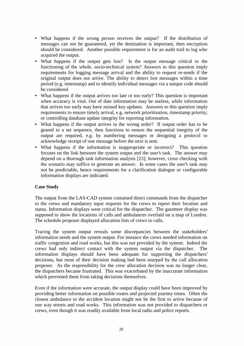
• What happens if the wrong person receives the output? If the distribution ofmessages can not be guaranteed, yet the destination is important, then encryptionshould be considered. Another possible requirement is for an audit trail to log whoacquired the output.
• What happens if the output gets lost? Is the output message critical to thefunctioning of the whole, socio-technical system? Answers to this question implyrequirements for logging message arrival and the ability to request re-sends if theoriginal output does not arrive. The ability to detect lost messages within a timeperiod (e.g. timestamp) and to identify individual messages via a unique code shouldbe considered.
• What happens if the output arrives too late or too early? This question is importantwhen accuracy is vital. Out of date information may be useless, while informationthat arrives too early may have missed key updates. Answers to this question implyrequirements to ensure timely arrival, e.g. network prioritisation, timestamp priority;or controlling database update integrity for reporting information.
• What happens if the output arrives in the wrong order? If output order has to begeared to a set sequence, then functions to ensure the sequential integrity of theoutput are required, e.g. by numbering messages or designing a protocol toacknowledge receipt of one message before the next is sent.
• What happens if the information is inappropriate or incorrect? This questionfocuses on the link between the system output and the user’s task. The answer maydepend on a thorough task information analysis [23]; however, cross checking withthe scenario may suffice to generate an answer. In some cases the user’s task maynot be predictable, hence requirements for a clarification dialogue or configurableinformation displays are indicated.
Case Study
The output from the LAS-CAD system contained direct commands from the dispatcherto the crews and mandatory input requests for the crews to report their location andstatus. Information displays were critical for the dispatcher. The gazetteer display wassupposed to show the locations of calls and ambulances overlaid on a map of London.The schedule proposer displayed allocation lists of crews to calls.
Tracing the system output reveals some discrepancies between the stakeholders’information needs and the system output. For instance the crews needed information ontraffic congestion and road works, but this was not provided by the system. Indeed thecrews had only indirect contact with the system output via the dispatcher. Theinformation displays should have been adequate for supporting the dispatchers’decisions, but most of their decision making had been usurped by the call allocationproposer. As the responsibility for the crew allocation decision was no longer clear,the dispatchers became frustrated. This was exacerbated by the inaccurate informationwhich prevented them from taking decisions themselves.
Even if the information were accurate, the output display could have been improved byproviding better information on possible routes and projected journey times. Often theclosest ambulance to the accident location might not be the first to arrive because ofone way streets and road works. This information was not provided to dispatchers orcrews, even though it was readily available from local radio and police reports.

21
Applying the outbound event heuristics points to potential problems in tracking systemoutput to the appropriate agents. Instructions from dispatchers might be received by theincorrect crew, so a crew identification check is necessary. This existed in the manualsystem. More seriously, instructions to crews can be overheard by the general publicand this can lead to undesirable consequences, such as voyeurs causing congestion atmajor accidents. Secure communications should be considered. As messages can getlost or arrive in the wrong order, a message recording log is needed to help dispatcherstrace call progress and diagnose miscommunication problems. Furthermore, messagescould be replayed from the log to avoid composing then again.
The effect of incorrect output for the dispatchers was one of the prime causes of systemfailure. Because accurate information is vital and the possibility of late or lostreporting events can not be ruled out, a requirement for cross checking accuracy needsshould have been investigated. This could be implemented by a simple instruction thatdispatchers make their understanding of the crew’s location explicit in the callallocation instructions. Any deviation should be detected by the crew and corrected.Error tolerances for inaccurate information and incorrect events should be studied toestablish their impact of performance of the user tasks. If the dispatcher can tolerate,say 1% inaccurate events without a performance degradation then correction protocolsmay not be necessary.
3.5 Social impact analysis
It should be stated at the outset that this is a difficult task to achieve as success dependson three unknowns:
(a) accurate social theories that predict human behaviour in response to computersystems.
(b) sufficient knowledge of a particular social system to make predictions using (a).
(c) a stable system environment so that predictions made by (a) using (b) remain validwhile the system is being constructed and implemented.
Given that the above three sources of knowledge are not complete, and some wouldcontend can not be complete, judgement of impact in the social domain must betentative. Nevertheless, some guidance can be given which may uncover a fewpotential problems.
Investigation begins by assessing the coupling between the social and technicalsystems. The system output commands, both direct or indirect, are counted. The morecommands there are, the closer the coupling between the social and technical systemswill be. Close coupling increases dependencies and makes the whole socio-technicalsystem prone to failure. General design advice is to divide the system into autonomoussub-systems to reduce coupling. Closely coupled human computer systems should bereviewed to either change the design for more automation (computer autonomy) orincrease human control and design the computer system for an advisory rather than acontrolling role

22
The style of coupling in socio-technical systems has implications for the organisationalculture. In hierarchical organisations, lines of authority are clear and powerrelationships defined by the structure. Close coupling may be possible in hierarchicalorganisations, although such systems may be brittle and prone to failure if the socialenvironment changes. Networked organisations have loose coupling, so the technicalsystems in such organisations should reflect this.
The scenario structure model is elaborated to propose different technical systemsolutions and consequently different system boundaries. The implications of people’sreactions to computer systems may vary widely according to where the boundary isdrawn. This involves partitioning tasks/activities between people and computers.Heuristics to guide these judgements have been given by several authors, e.g.[24], [25],[26]. Some impact heuristics to bear in mind at the requirements stage are that:
1. Excessive automation diminishes human responsibility. This may in turn have anadverse impact on motivation.
2. Excessive automation diminishes human awareness of the whole system; thisreduces the user’s capacity to respond to abnormal events. The dangers of this insafety critical systems are pointed out by Leveson [27].
3. Automation which leaves users with menial, undemanding tasks will increaseboredom, lower motivation and lead to more errors.
4. Automation with closely coupled interaction imposes new work practices on people.This may cause them to reject the system as it constrains human activity in anunnatural manner.
5. Coupling between users and automated systems should be sensitive to the users’skills and knowledge. If the users have to take decisions imposed on them by thecomputer system, then they should be given the necessary training.
6. Care should be exercised to ensure that introduction of the computer system doesnot alter responsibilities and power relationships between people. Although newcomputer systems invariably alter responsibilities, these changes should be assessedand ameliorated where possible. Furthermore, the changes should be explained andjustified to the users .
Once the technical system boundary has been established, power and authority relationscan be traced to check whether the system output will fulfil users’ goals, and thatauthority relationships are clear and do not contradict each other (e.g. two agents incharge of one activity, conflict in authority). Information output may have unexpectedconsequences. The effect of providing information for an agent should be assessed tosee if it will alter that person’s role or potential power. For instance providing oneperson with another person’s work schedule gives an opportunity for mischief, e.g. thefirst agent may tell the second to do something in the wrong order. Such problems aredifficult to detect a priori, and a better defence is to have well motivated, well trainedstaff who are unlikely to create misdemeanours. However, in financial applicationswhere security is paramount, asking whether information is likely to be misused by areceiving agent is advisable. Power relations may be implicit in the form of incentivesand monitoring results rather than by direct reporting. The scenario structure model isused to assess the impact of commands by tracing the output event to its destination inthe social system and asking the following questions:

23
• Does system output trigger an activity that a human agent is responsible for? Thisindicates a direct command.
• Is the system output a necessary input for human activity or does it imply the needfor decision making? This suggests an indirect command.
• Is system output a helpful, although not strictly necessary, resource for completionof a human activity? This indicates an indirect dependency.
Once system commands have been identified their impact can be assessed by tracingthe output to the recipient agents and their goals, responsibilities, roles and authority inthe social domain. The following questions point out potential problems and guide theanalyst towards issues that may need to be investigated.
For each system output-command, trace which agents will be involved to assess: if theappropriate person being asked to comply with the command. The answer can befound by:
a) inspecting the agent’s properties to determine whether they have the necessary skillsor knowledge to undertake the task or take the decision. If they do not, then there areimplications for personnel selection or training.
b) inspecting the role and tasks the agent is responsible for. If the command is being
directed to the wrong person then the social system should be changed. c) Can the person respond in time and in an appropriate manner? Investigate the time
demands for decision making or carrying out tasks and checking the user’s trainingand role.
The next step is to establish whether the users are likely to comply with systemcommands. Possible reasons why they may not are lack of motivation, or that they seethe command as an imposition on their responsibilities. Pointers to answers may befound by tracing the responsibility and authority relationships of the agent to ascertain:
a) does the command create a clash in responsibilities, e.g. the system asks an agent totake a decision which exceeds their responsibility?
b) does the command infringe the user’s authority, e.g. the system requires the user totake a decision at the wrong time or takes the decision for them?
c) does the command alter the power relationships between human agents, e.g. thecommand diminishes one person’s authority and increase another’s?
A complete investigation of these questions goes beyond requirements analysis intosocio-technical system design.
3.6 Stakeholder analysis
Finally a stakeholder cost benefit analysis can help to summarise the previousinvestigations and highlight potential reactions of personnel to introduction of the newsystem. This technique assess the impact of system design on different users orstakeholder groups. The analysis can be repeated on alternative system designs to

24
assess trade-offs for various stakeholder. Each stakeholder group is assessed againstthe following questions:
• will the new system de-skill their job? Excessive automation is often the culprit.• could the new system threaten their job security?• will their responsibilities be diminished by the new system? This may be caused by
automating part of a stakeholder’s job or re-distributing responsibilities in the socialsystem.
• will the system adversely effect working practices? This may have several causes,such as excessive coupling which directs human operators and allows no flexibility;removing the ability to take decisions and autonomous action; change in authorityrequiring clearance before action can be taken; and not providing sufficientinformation to complete a task
The potential benefits of enhanced responsibility, more stimulating job descriptions,opportunities for self advancement and promotion should be offset against thesedownsides. If any stakeholder group has a preponderance of downsides then theirmotivation and willingness to co-operate with the new system will be decreased. Thiscan lead to more mistakes, non-compliance with responsibilities and duties andultimately sabotage. The answers may be gathered by interviewing stakeholdersdirectly for their opinions or by judgement of independent experts. Cost benefitanalysis may be conducted at the sub-system or component level if necessary.
Case Study
The LAS-CAD system was closely coupled as a consequence of event-messagesbetween the crews and the dispatchers. System output imposed a large number ofcommands on the crews to report their location and status. The call allocation proposeralso functioned as an indirect command to the dispatcher because the decision makinghad been nearly completely automated.
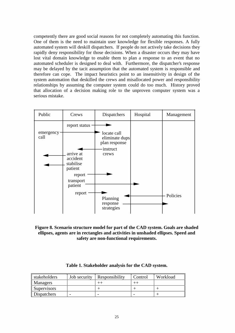
The scenario structure model for part of the CAD system is illustrated in figure 8. Thisshows the relationships between the agents, goals and activities that are traced duringthe impact analysis. As the figure shows the dispatchers role has become complex withmany responsibilities.
When the costs and benefits for each group of stakeholders are analysed it can be seenthat management were the only significant gainers; see table 1. Both the crews anddispatchers suffered from fears of deskilling and possible loss of their jobs as a resultof the system. The system also imposed more demands on the crews than the manualsystem. It is not surprising that the crews did not comply with the reporting proceduresand the dispatchers became demoralised and frustrated.
Inspecting the agents’ roles and tasks suggests that the manual system had anappropriate allocation of tasks to agents. The dispatchers and crews both had extensivedomain knowledge that they used to carry out tasks. This might present a problem fornew personnel, so training had to be thorough. The call allocation proposer infringedthe dispatchers’ decision making authority as it never had accurate information forplanning. Even if the computer system had accurate information to function
25
competently there are good social reasons for not completely automating this function.One of them is the need to maintain user knowledge for flexible responses. A fullyautomated system will deskill dispatchers. If people do not actively take decisions theyrapidly deny responsibility for those decisions. When a disaster occurs they may havelost vital domain knowledge to enable them to plan a response to an event that noautomated scheduler is designed to deal with. Furthermore, the dispatcher’s responsemay be delayed by the tacit assumption that the automated system is responsible andtherefore can cope. The impact heuristics point to an insensitivity in design of thesystem automation that deskilled the crews and misallocated power and responsibilityrelationships by assuming the computer system could do too much. History provedthat allocation of a decision making role to the unproven computer system was aserious mistake.
Public Crews Dispatchers ManagementHospital
report status
emergency call
plan responseinstruct crewsarrive at
accidentstabilise patient
reporttransport patient
reportPolicies
Planning response strategies
locate call eliminate dups
Figure 8. Scenario structure model for part of the CAD system. Goals are shadedellipses, agents are in rectangles and activities in unshaded ellipses. Speed and
safety are non-functional requirements.
Table 1. Stakeholder analysis for the CAD system.
stakeholders Job security Responsibility Control WorkloadManagers ++ ++Supervisors + + +Dispatchers - - - +

26
Ambulancecrew
- - -
4. Discussion
Retrospective case studies inevitably suffer from the benefit of hindsight. It is not clearwhat the relative contribution of the method and its human user were to therecommendations produced by the analysis. The LAS inquest report dwells on failuresin the social domains such as the failure to consult the ambulance crews and theproblems of deskilling the dispatchers; however, we have uncovered a wealth ofproblems that are not mentioned in the report, so we may make some modest claims foreffectiveness of the method. Moreover, we may hypothesise that the method hasuncovered problems which are still inherent in the current system. The inquiry reportblamed management for an inept approach to system development and ascribes themajor causes of failure to hardware and system integration issues, such ascommunications failure between the CAD and AVLS systems, poor software testingand inadequate preparation for system cut-over. We contend that had the developerscorrected all these mistakes, there is still a very good chance of failure because of poorrequirements analysis in the social domain.
Parts of the scenario based method reported in this paper are related to the enterprisemodelling approach of Mylopoulos et al [13] and Chung [14]. They create models ofthe system and its immediate environment using similar semantics. Their strategicdependency and rationale model allow tracing of dependencies between agents, thegoals and tasks with limited reasoning to identify trade offs between functionalrequirements and non-functional requirements (referred to as soft goals). However thei* enterprise modelling method does not give advice about creating enterprise models,nor does it contain detailed event dependency analysis such as we have reported.
Dependencies between systems and their environment have been analysed in detail byJackson and Zave [28] who point out that input events impose obligations on a requiredsystem. They propose a formalism for modelling such dependencies. Formalmodelling is applicable to the class of system they implicitly analyse, e.g. real time andsafety critical applications, but it is less clear how such models can deal with theuncertainties of human behaviour. Models of user’s goals and their operationalisation insystem requirements can be described in the KAOS language [29] which enablesbehavioural requirements and constraints to be formally specified; however, KAOSdoes not use scenarios as test data for requirement validation. We believe our scenariobased approach is more appropriate to deal with uncertainty caused by humanbehaviour as it focuses on eliciting requirements for dialogue and system function torepair problems caused by unreliable human behaviour.
So far the method has not dealt with non functional requirements. Scenarios cancapture the necessary criteria which would have to be expressed in quantifiable terms,for instance by the Goals- Quality-metric approach [30], or in a similar manner byBoehm’s [31] win-win analysis. The dependency checking proposed in the paper lends
27
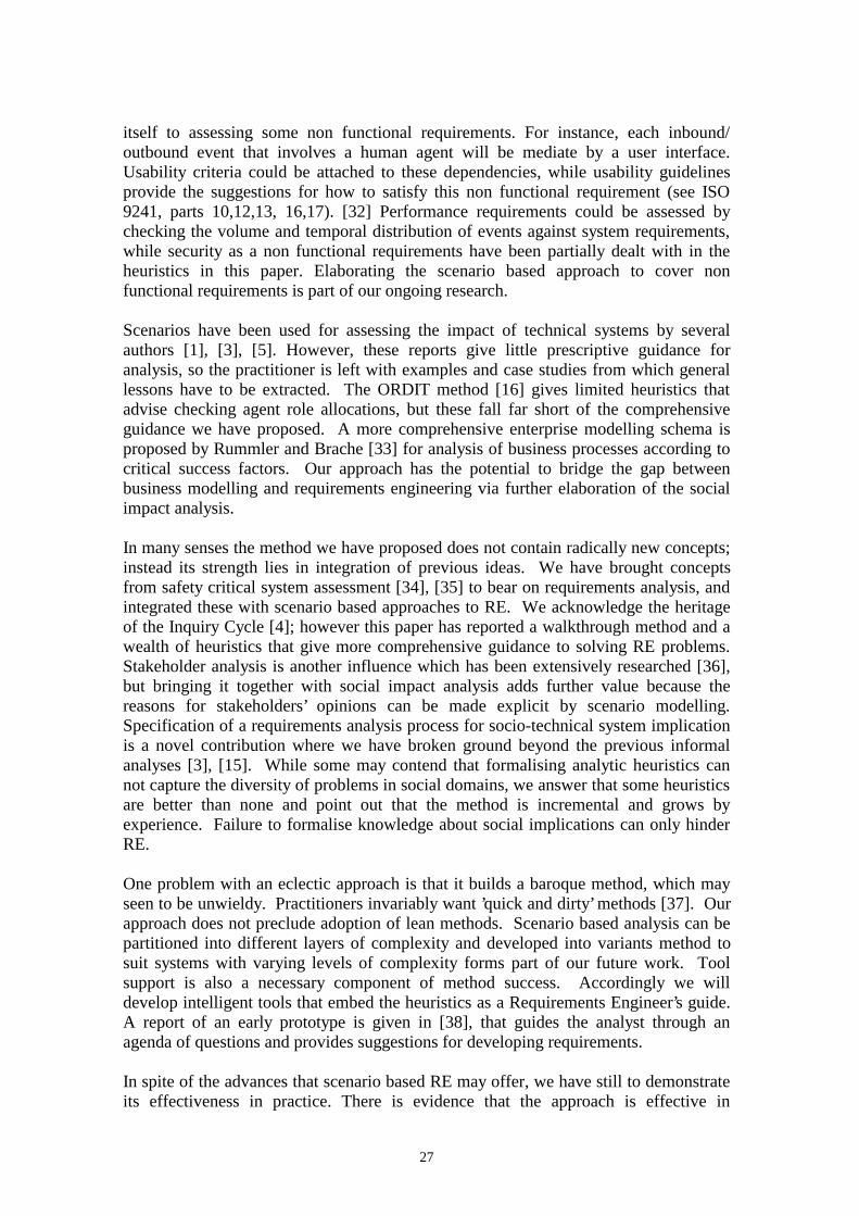
itself to assessing some non functional requirements. For instance, each inbound/outbound event that involves a human agent will be mediate by a user interface.Usability criteria could be attached to these dependencies, while usability guidelinesprovide the suggestions for how to satisfy this non functional requirement (see ISO9241, parts 10,12,13, 16,17). [32] Performance requirements could be assessed bychecking the volume and temporal distribution of events against system requirements,while security as a non functional requirements have been partially dealt with in theheuristics in this paper. Elaborating the scenario based approach to cover nonfunctional requirements is part of our ongoing research.
Scenarios have been used for assessing the impact of technical systems by severalauthors [1], [3], [5]. However, these reports give little prescriptive guidance foranalysis, so the practitioner is left with examples and case studies from which generallessons have to be extracted. The ORDIT method [16] gives limited heuristics thatadvise checking agent role allocations, but these fall far short of the comprehensiveguidance we have proposed. A more comprehensive enterprise modelling schema isproposed by Rummler and Brache [33] for analysis of business processes according tocritical success factors. Our approach has the potential to bridge the gap betweenbusiness modelling and requirements engineering via further elaboration of the socialimpact analysis.
In many senses the method we have proposed does not contain radically new concepts;instead its strength lies in integration of previous ideas. We have brought conceptsfrom safety critical system assessment [34], [35] to bear on requirements analysis, andintegrated these with scenario based approaches to RE. We acknowledge the heritageof the Inquiry Cycle [4]; however this paper has reported a walkthrough method and awealth of heuristics that give more comprehensive guidance to solving RE problems.Stakeholder analysis is another influence which has been extensively researched [36],but bringing it together with social impact analysis adds further value because thereasons for stakeholders’ opinions can be made explicit by scenario modelling.Specification of a requirements analysis process for socio-technical system implicationis a novel contribution where we have broken ground beyond the previous informalanalyses [3], [15]. While some may contend that formalising analytic heuristics cannot capture the diversity of problems in social domains, we answer that some heuristicsare better than none and point out that the method is incremental and grows byexperience. Failure to formalise knowledge about social implications can only hinderRE.
One problem with an eclectic approach is that it builds a baroque method, which mayseen to be unwieldy. Practitioners invariably want ’quick and dirty’ methods [37]. Ourapproach does not preclude adoption of lean methods. Scenario based analysis can bepartitioned into different layers of complexity and developed into variants method tosuit systems with varying levels of complexity forms part of our future work. Toolsupport is also a necessary component of method success. Accordingly we willdevelop intelligent tools that embed the heuristics as a Requirements Engineer’s guide.A report of an early prototype is given in [38], that guides the analyst through anagenda of questions and provides suggestions for developing requirements.
In spite of the advances that scenario based RE may offer, we have still to demonstrateits effectiveness in practice. There is evidence that the approach is effective in
28
empirical studies of earlier versions of the method which did use scenarios but withoutthe heuristics [5]. Further validation with industrial case studies is part of our researchagenda. Also we will improve the social impact analysis where we have only justbegun to address the complexities of understanding what might go wrong whencomputer system are introduced into the social domain.
Acknowledgements
The author would like to thank members of the City CREWS team for comments onearlier drafts of this paper. This research was partially supported by the EU long termresearch project CREWS- Co-operative Requirements Engineering With Scenarios,partners RWTH-Aachen (project co-ordinator), City University, London, University ofParis I, FUNDP, University of Namur.
References
1. Carroll J.M. The scenario perspective on system development. In: J.M. Carroll (ed.)Scenario-based design: envisioning work and technology in system development. J.Wiley, New York, 1995.
2. Jacobson I., Christerson M., Jonsson P., and Overgaard. Object oriented software
engineering: a use case driven approach. Addison Wesley, Reading MA, 1992. 3. Kyng M. Creating contexts for design. In: J.M. Carroll (ed.) Scenario-based design:
envisioning work and technology in system development. J. Wiley, New York,1995. 85-108.
4. Potts C, Takahashi K, Anton A. Inquiry based requirements analysis. IEEE
Software, March 1994, 21-32. 5. Sutcliffe A.G. A technique combination approach to requirements engineering. In
Proceedings of the 3rd International Symposium on Requirements Engineering,Anapolis, January 1997, IEEE Computer Society Press.
6. Potts C, Takahashi K, Smith J, Ora K. An evaluation of inquiry based requirements
analysis for an Internet service. In: Zave P, Harrison MD, (ed.) Proceedings of RE’95: Second International Symposium on Requirements Engineering. IEEEComputer Society Press, 1995, 27-34.
7. Sutcliffe A.G. Requirements rationales: integrating approaches to requirements
analysis. In: Olson GM, Schuon S, (ed.) Proceedings of Designing InteractiveSystems, DIS ’95. ACM Press, New York, 1995, 33-42.
8. Graham I., 1996, ’Task Scripts, Use Cases and Scenarios in Object-Oriented
Analysis’, Object-Oriented Systems 3, 123-142. 9. Cockburn A., 1995, ’Structuring Use Cases with Goals’,
http://members.aol.com/acockburn/papers/usecase.htm
29
10. Mullery, G.P., CORE- a method for controlled requirements expression. INSystems and Software Requirements Engineering, Eds Thayer R.H. and DorfmanM., pp 304-131, IEEE Computer Society Press, Los Alamitos, 1987.
11. E.E.Yourdon. Modern Structured Analysis. Prentice Hall, (1989). 12. Jackson M. Software requirements and specifications. Addison-Wesley, Reading,
MA, 1995. 13. Mylopoulos J, Chung L, Nixon B. Representing and using non-functional
requirements: a process-oriented approach. IEEE Transactions on SoftwareEngineering 1992; 18 (6), 483-497.
14. Chung L. Representing and using non-functional requirements: a process-oriented
approach. Dept of Computer Science, University of Toronto, 1993. 15. Eason, K.D., Harker, S.D. and Olphert, C.W. Representing socio-technical system
options in the development of new forms of work organization, European Journal ofWork and Organizational Psychology, 5(3), 1996, 399-420.
16. Harker S.D., Eason K.D., Dobson JE. The change and evolution of requirements as
a challenge to the practice of software engineering. In: IEEE Symposium onRequirements Engineering, RE ’93, San Diego, CA. IEEE Computer Society Press,1993, 266-27.
17. Rational Corporation. UML: Unified Modelling Language, available from Rational
Corp., Boulder Colorado. 1997. 18. Maiden N.A.M., Sutcliffe A.G., Requirements critiquing using domain abstractions.
In: Proceedings First International Conference on Requirements Engineering, J.Siddiqi (ed.) IEEE Computer Society Press, 1994, 184-193.
19. Allen, J. 1985, A common sense theory of time. In Proceedings of International
Joint Conference on Artificial Intelligence,1985. 20. HMSO. Report of the Inquiry into the London Ambulance Service. HMSO, London
1993. 21. Jackson M.A., System development. Prentice Hall, 1983. 22. Sutcliffe A.G., Jackson system development. Prentice Hall, 1988. 23. Sutcliffe A.G., Task Related Information Analysis, International Journal of Human
Computer Studies, Vol 47, pp 223-257. 1997. 24. Bailey, R.W., Human performance engineering. Prentice Hall, 1982. 25. Shneiderman B., Designing the user system interface. 3rd edition, Morgan
Kaufmann, 1997.

30
26. Sutcliffe, A.G., Human computer interface design. 2nd edition, Macmillan, London,1994.
27. Leveson N., Safeware: system safety and computers. Addison Wesley, Reading
MA, 1995. 28. Jackson M, Zave P. Domain descriptions. In: IEEE Symposium on Requirements
Engineering. IEEE Computer Society Press, 1993, 56-64. 29. van Lamsweerde A., Darimont, R and Massonet Ph., Goal directed elaboration of
requirements for a meeting scheduler: problems and lessons learnt. In proceedingsof RE-95, IEEE International Symposium on Requirements Engineering, (York,UK), Eds Harrison M.D and Zave P, pp 194-203, IEEE Computer Society Press,1995.
30. Basili, V.R. and Rombach, H. D. "The TAME project: Towards improvement-
oriented software environments’, IEEE Transactions on Software Engineering, vol.14, no. 6, pp. 758-773, 1988.
31. Boehm, B. and Hoh In, "Identifying Quality-Requirement Conflicts", IEEE
Software, pp. 25-35, March 1996. 32. ISO 9241 (1997), Ergonomic requirements for office systems Visual display
terminals. Parts 10, 11,16 International standards, parts 1-9, 12-15, 17, draftstandards; International standards organisation, Switzerland, available from nationalstandards organisations.
33. Rummler G.A. and Brache A.P., Improving Performance: How to manage the white
space on the organization chart. Jossey-Bass, San Francisco, 1995 34. Hollnagel E. Human reliability analysis: context and control, Academic Press,
London, 1993. 35. Reason J.T. Human error. Cambridge University Press, 1990. 36. Macaulay L. Requirements Engineering. Springer Verlag, Berlin, 1996. 37. Sommerville, I. and Sawyer, P. "Requirements Engineering: A Good Practice
Guide", John Wiley & Sons, 1997. 38. Minocha S., Maiden N., Ryan M. and Manning K. A cooperative scenario-based
approach to acquisition and validation of system requirements: how exceptions canhelp. In: Proceedings of the Glasgow Safety Critical System Engineering Workshop.1997.