SCALANCE XB-200 · devices of the SCALANCE XB-200 product group named above in the section on...
60
SCALANCE XB-200 ___________________ ___________________ ___________________ ___________________ ___________________ ___________________ ___________________ ___________________ ___________________ SIMATIC NET Industrial Ethernet switches SCALANCE XB-200 Operating Instructions 02/2015 C79000-G8976-C359-01 Introduction Safety notices 1 Description of the device 2 Installation 3 Connecting up 4 Upkeep and maintenance 5 Technical specifications 6 Dimension drawings 7 Approvals A
Transcript of SCALANCE XB-200 · devices of the SCALANCE XB-200 product group named above in the section on...

SCALANCE XB-200
___________________
___________________
___________________
___________________
___________________
___________________
___________________
___________________
___________________
SIMATIC NET
Industrial Ethernet switches SCALANCE XB-200
Operating Instructions
02/2015 C79000-G8976-C359-01
Introduction
Safety notices 1
Description of the device 2
Installation 3
Connecting up 4
Upkeep and maintenance 5
Technical specifications 6
Dimension drawings 7
Approvals A
Siemens AG Division Process Industries and Drives Postfach 48 48 90026 NÜRNBERG GERMANY
C79000-G8976-C359-01 Ⓟ 11/2014 Subject to change
Copyright © Siemens AG 2015. All rights reserved
Legal information Warning notice system
This manual contains notices you have to observe in order to ensure your personal safety, as well as to prevent damage to property. The notices referring to your personal safety are highlighted in the manual by a safety alert symbol, notices referring only to property damage have no safety alert symbol. These notices shown below are graded according to the degree of danger.
DANGER indicates that death or severe personal injury will result if proper precautions are not taken.
WARNING indicates that death or severe personal injury may result if proper precautions are not taken.
CAUTION indicates that minor personal injury can result if proper precautions are not taken.
NOTICE indicates that property damage can result if proper precautions are not taken.
If more than one degree of danger is present, the warning notice representing the highest degree of danger will be used. A notice warning of injury to persons with a safety alert symbol may also include a warning relating to property damage.
Qualified Personnel The product/system described in this documentation may be operated only by personnel qualified for the specific task in accordance with the relevant documentation, in particular its warning notices and safety instructions. Qualified personnel are those who, based on their training and experience, are capable of identifying risks and avoiding potential hazards when working with these products/systems.
Proper use of Siemens products Note the following:
WARNING Siemens products may only be used for the applications described in the catalog and in the relevant technical documentation. If products and components from other manufacturers are used, these must be recommended or approved by Siemens. Proper transport, storage, installation, assembly, commissioning, operation and maintenance are required to ensure that the products operate safely and without any problems. The permissible ambient conditions must be complied with. The information in the relevant documentation must be observed.
Trademarks All names identified by ® are registered trademarks of Siemens AG. The remaining trademarks in this publication may be trademarks whose use by third parties for their own purposes could violate the rights of the owner.
Disclaimer of Liability We have reviewed the contents of this publication to ensure consistency with the hardware and software described. Since variance cannot be precluded entirely, we cannot guarantee full consistency. However, the information in this publication is reviewed regularly and any necessary corrections are included in subsequent editions.
SCALANCE XB-200 Operating Instructions, 02/2015, C79000-G8976-C359-01 3
Introduction
Purpose of the Operating Instructions These operating instructions support you when installing and connecting up devices of the SCALANCE XB-200 product group.
The configuration and the integration of the devices in a network are not described in these operating instructions.
Validity of the Operating Instructions These operating instructions apply to the following devices:
● SCALANCE XB208
● SCALANCE XB205-3 (SC)
● SCALANCE XB205-3LD (SC)
● SCALANCE XB205-3
● SCALANCE XB216
● SCALANCE XB213-3 (SC)
● SCALANCE XB213-3LD (SC)
● SCALANCE XB213-3
Unless mentioned otherwise, the descriptions in these operating instructions refer to all devices of the SCALANCE XB-200 product group named above in the section on validity.
Designations used Classification Description Terms used Product line The product line includes all devices and variants of all product groups.
If information applies to all product groups within the product line, the term SCALANCE X-200 is used.
SCALANCE X-200
Product group If information applies to all devices and variants of a product group, the term SCALANCE XB-200 is used.
SCALANCE XB-200
Device If information relates to a specific device, the device name is used. e.g. SCALANCE XB205-3
Introduction
SCALANCE XB-200 4 Operating Instructions, 02/2015, C79000-G8976-C359-01
Documentation on configuration You will find detailed information on configuring the devices in the following configuration manuals:
● SCALANCE XB-200 Web Based Management
● SCALANCE XB-200 Command Line Interface
You will find the configuration manuals here:
● on the data medium that ships with some products:
– Product CD / product DVD
– SIMATIC NET Manual Collection
● On the Internet pages of Siemens Industry Online Support.
Further documentation In the system manuals "Industrial Ethernet / PROFINET Industrial Ethernet" and "Industrial Ethernet / PROFINET passive network components", you will find information on other SIMATIC NET products that you can operate along with the devices of this product line in an Industrial Ethernet network.
There, you will find among other things optical performance data of the communications partner that you require for the installation.
You will find the system manuals here:
● On the data medium that ships with some products:
– Product CD / product DVD
– SIMATIC NET Manual Collection
● On the Internet pages of Siemens Industry Online Support under the following entry IDs:
– 27069465 (http://support.automation.siemens.com/WW/view/en/27069465) Industrial Ethernet / PROFINET Industrial Ethernet System Manual
– 84922825 (http://support.automation.siemens.com/WW/view/en/84922825) Industrial Ethernet / PROFINET - Passive network components System Manual
Introduction
SCALANCE XB-200 Operating Instructions, 02/2015, C79000-G8976-C359-01 5
SIMATIC NET manuals You will find SIMATIC NET manuals on the Internet pages of Siemens Industry Online Support:
● using the search function:
Link to Siemens Industry Online Support (http://support.automation.siemens.com/WW/llisapi.dll?func=cslib.csinfo2&aktprim=99&lang=en)
Enter the entry ID of the relevant manual as the search item.
● In the navigation panel on the left hand side in the area "Industrial Communication":
Link to the area "Industrial Communication" (http://support.automation.siemens.com/WW/llisapi.dll?func=cslib.csinfo&lang=de&siteid=csius&aktprim=0&extranet=standard&viewreg=WW&objid=10805878&treeLang=en)
Go to the required product group and make the following settings: tab "Entry list", Entry type "Manuals"
You will find the documentation for the SIMATIC NET products relevant here on the data medium that ships with some products:
● Product CD / product DVD
● SIMATIC NET Manual Collection
SIMATIC NET glossary Explanations of many of the specialist terms used in this documentation can be found in the SIMATIC NET glossary.
You will find the SIMATIC NET glossary here:
● SIMATIC NET Manual Collection or product DVD
The DVD ships with certain SIMATIC NET products.
● On the Internet under the following entry ID:
50305045 (http://support.automation.siemens.com/WW/view/en/50305045)
Catalogs You will find the order numbers for the Siemens products of relevance here in the following catalogs:
● SIMATIC NET Industrial Communication / Industrial Identification, catalog IK PI
● SIMATIC Products for Totally Integrated Automation and Micro Automation, catalog ST 70
● Industry Mall - catalog and ordering system for automation and drive technology, Online catalog (https://eb.automation.siemens.com/goos/WelcomePage.aspx?regionUrl=/en&language=en)
You can request the catalogs and additional information from your Siemens representative.

Introduction
SCALANCE XB-200 6 Operating Instructions, 02/2015, C79000-G8976-C359-01
Unpacking and checking
WARNING
Do not use any parts that show evidence of damage
If you use damaged parts, there is no guarantee that the device will function according to the specification.
If you use damaged parts, this can lead to the following problems: • Injury to persons • Loss of the approvals • Violation of the EMC regulations • Damage to the device and other components
Use only undamaged parts.
1. Make sure that the package is complete.
2. Check all the parts for transport damage.
Security information Siemens provides products and solutions with industrial security functions that support the secure operation of plants, solutions, machines, equipment and/or networks. They are important components in a holistic industrial security concept. With this in mind, Siemens’ products and solutions undergo continuous development. Siemens recommends strongly that you regularly check for product updates.
For the secure operation of Siemens products and solutions, it is necessary to take suitable preventive action (e.g. cell protection concept) and integrate each component into a holistic, state-of-the-art industrial security concept. Third-party products that may be in use should also be considered. For more information about industrial security, visit http://www.siemens.com/industrialsecurity.
To stay informed about product updates as they occur, sign up for a product-specific newsletter. For more information, visit http://support.automation.siemens.com.
Trademarks The following and possibly other names not identified by the registered trademark sign ® are registered trademarks of Siemens AG:
SIMATIC NET, SCALANCE, C-PLUG, OLM
SCALANCE XB-200 Operating Instructions, 02/2015, C79000-G8976-C359-01 7
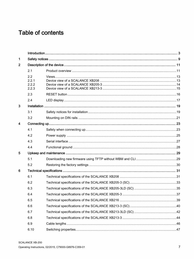
Table of contents
Introduction ............................................................................................................................................. 3
1 Safety notices ......................................................................................................................................... 9
2 Description of the device ....................................................................................................................... 11
2.1 Product overview .................................................................................................................... 11
2.2 Views....................................................................................................................................... 13 2.2.1 Device view of a SCALANCE XB208 ..................................................................................... 13 2.2.2 Device view of a SCALANCE XB205-3 .................................................................................. 14 2.2.3 Device view of a SCALANCE XB213-3 .................................................................................. 15
2.3 RESET button ......................................................................................................................... 16
2.4 LED display ............................................................................................................................. 17
3 Installation ............................................................................................................................................ 19
3.1 Safety notices for installation .................................................................................................. 19
3.2 Mounting on DIN rails ............................................................................................................. 21
4 Connecting up ....................................................................................................................................... 23
4.1 Safety when connecting up ..................................................................................................... 23
4.2 Power supply .......................................................................................................................... 25
4.3 Serial interface ........................................................................................................................ 27
4.4 Functional ground ................................................................................................................... 28
5 Upkeep and maintenance ..................................................................................................................... 29
5.1 Downloading new firmware using TFTP without WBM and CLI ............................................. 29
5.2 Restoring the factory settings ................................................................................................. 30
6 Technical specifications ........................................................................................................................ 31
6.1 Technical specifications of the SCALANCE XB208 ............................................................... 31
6.2 Technical specifications of the SCALANCE XB205-3 (SC) .................................................... 33
6.3 Technical specifications of the SCALANCE XB205-3LD (SC) ............................................... 35
6.4 Technical specifications of the SCALANCE XB205-3 ............................................................ 37
6.5 Technical specifications of the SCALANCE XB216 ............................................................... 39
6.6 Technical specifications of the SCALANCE XB213-3 (SC) .................................................... 40
6.7 Technical specifications of the SCALANCE XB213-3LD (SC) ............................................... 42
6.8 Technical specifications of the SCALANCE XB213-3 ............................................................ 44
6.9 Cable lengths .......................................................................................................................... 46
6.10 Switching properties ................................................................................................................ 47
Table of contents
SCALANCE XB-200 8 Operating Instructions, 02/2015, C79000-G8976-C359-01
7 Dimension drawings .............................................................................................................................. 49
A Approvals ............................................................................................................................................. 53
Index .................................................................................................................................................... 59
SCALANCE XB-200 Operating Instructions, 02/2015, C79000-G8976-C359-01 9
Safety notices 1
Read the safety notices Note the following safety notices. These relate to the entire working life of the device.
You should also read the safety notices relating to handling in the individual sections, particularly in the sections "Installation" and "Connecting up".
Safety notices on use in hazardous areas
General safety notices relating to protection against explosion
WARNING
EXPLOSION HAZARD
DO NOT OPEN WHEN ENERGIZED.
Safety notices when using the device according to Hazardous Locations (HazLoc)
If you use the device under HazLoc conditions you must also keep to the following safety notices in addition to the general safety notices for protection against explosion:
This equipment is suitable for use in Class I, Division 2, Groups A, B, C and D or non-hazardous locations only.
This equipment is suitable for use in Class I, Zone 2, Group IIC or non-hazardous locations only.
Safety notices
SCALANCE XB-200 10 Operating Instructions, 02/2015, C79000-G8976-C359-01

SCALANCE XB-200 Operating Instructions, 02/2015, C79000-G8976-C359-01 11
Description of the device 2 2.1 Product overview
Article numbers Device Description Article number
(Ethernet/IP) SCALANCE XB208 8 x 10/100 Mbps RJ-45 ports 6GK5 208-0BA00-2TB2 SCALANCE XB205-3 (SC) 5 x 10/100 Mbps RJ-45 ports, 3 x 10/100 Mbps SC ports,
multimode fiber-optic cable 6GK5 205-3BD00-2TB2
SCALANCE XB205-3LD (SC) 5 x 10/100 Mbps RJ-45 ports, 3 x 10/100 Mbps SC ports, single mode fiber-optic cable
6GK5 205-3BF00-2TB2
SCALANCE XB205-3 5 x 10/100 Mbps RJ-45 ports, 3 x 10/100 Mbps ST ports, multimode fiber-optic cable
6GK5 205-3BB00-2TB2
SCALANCE XB216 16 x 10/100 Mbps RJ-45 ports 6GK5 216-0BA00-2TB2 SCALANCE XB213-3 (SC) 13 x 10/100 Mbps RJ-45 ports, 3 x 10/100 Mbps SC ports,
multimode fiber-optic cable 6GK5 213-3BD00-2TB2
SCALANCE XB213-3LD (SC) 13 x 10/100 Mbps RJ-45 ports, 3 x 10/100 Mbps SC ports, single mode fiber-optic cable
6GK5 213-3BF00-2TB2
SCALANCE XB213-3 13 x 10/100 Mbps RJ-45 ports, 3 x 10/100 Mbps ST ports, multimode fiber-optic cable
6GK5 213-3BB00-2TB2
Type designation The type designation of a SCALANCE XB-200 is made up of several parts that have the following meaning:
Interfaces of devices with optical connectors: Interface Property (SC) 10/100 Mbps SC port, multimode fiber-optic cable, up to 5 km LD (SC) 10/100 Mbps SC port, single mode fiber-optic cable, up to 26 km [-] 10/100 Mbps ST port, multimode fiber-optic cable, up to 5 km
Description of the device 2.1 Product overview
SCALANCE XB-200 12 Operating Instructions, 02/2015, C79000-G8976-C359-01
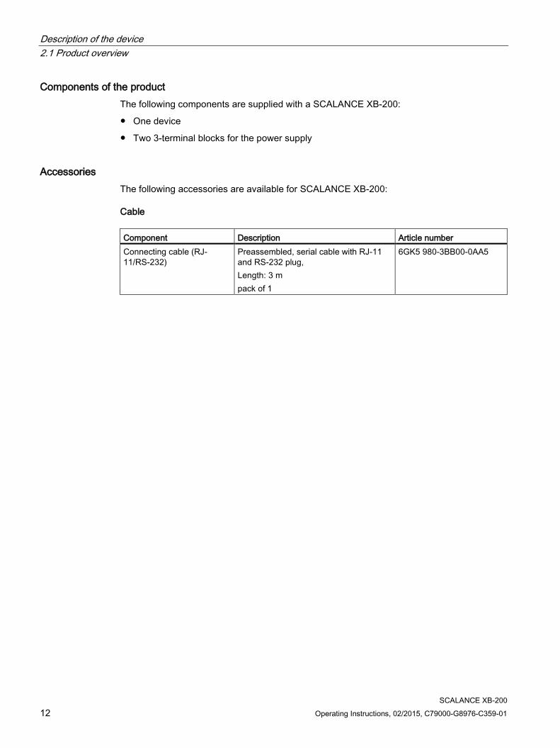
Components of the product The following components are supplied with a SCALANCE XB-200:
● One device
● Two 3-terminal blocks for the power supply
Accessories The following accessories are available for SCALANCE XB-200:
Cable Component Description Article number Connecting cable (RJ-11/RS-232)
Preassembled, serial cable with RJ-11 and RS-232 plug, Length: 3 m pack of 1
6GK5 980-3BB00-0AA5

Description of the device 2.2 Views
SCALANCE XB-200 Operating Instructions, 02/2015, C79000-G8976-C359-01 13
2.2 Views
2.2.1 Device view of a SCALANCE XB208 The following figure shows an overview of the components of the SCALANCE XB208.
① Electrical ports with port LEDs ② Power supply with connector for grounding ③ Serial interface ④ "RESET" button (rear) ⑤ Fault LED
Description of the device 2.2 Views
SCALANCE XB-200 14 Operating Instructions, 02/2015, C79000-G8976-C359-01
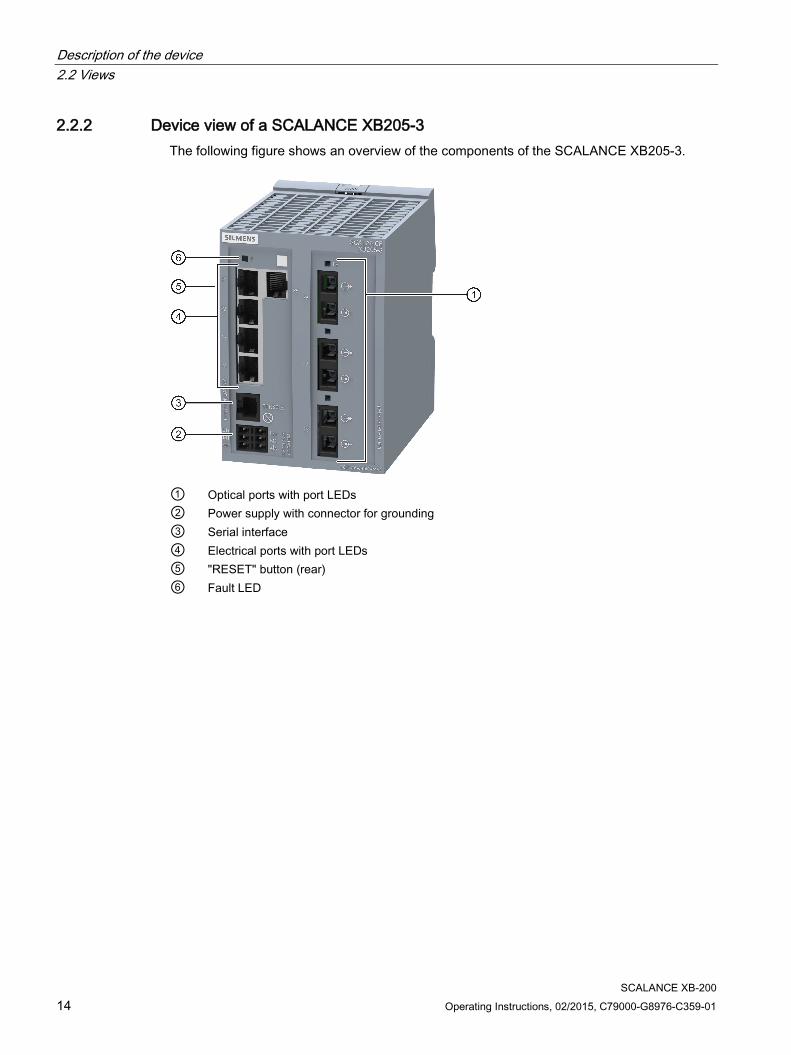
2.2.2 Device view of a SCALANCE XB205-3 The following figure shows an overview of the components of the SCALANCE XB205-3.
① Optical ports with port LEDs ② Power supply with connector for grounding ③ Serial interface ④ Electrical ports with port LEDs ⑤ "RESET" button (rear) ⑥ Fault LED

Description of the device 2.2 Views
SCALANCE XB-200 Operating Instructions, 02/2015, C79000-G8976-C359-01 15
2.2.3 Device view of a SCALANCE XB213-3 The following figure shows an overview of the components of the SCALANCE XB213-3.
① Optical ports with port LEDs ② Power supply with connector for grounding ③ Serial interface ④ Electrical ports with port LEDs ⑤ "RESET" button (rear) ⑥ Fault LED

Description of the device 2.3 RESET button
SCALANCE XB-200 16 Operating Instructions, 02/2015, C79000-G8976-C359-01
2.3 RESET button
Position The "RESET" button is located on the rear of the SCALANCE XB-200.
Figure 2-1 Position of the "RESET" button, for example on the SCALANCE XB213-3
Resetting the device to factory defaults
Note
If you reset, all the changes you have made will be overwritten by factory defaults.
To reset the device to the factory defaults, follow the steps below:
1. Press the "RESET" button, for example with a screwdriver and keep it pressed for approximately 12 seconds.
After 9 seconds, the fault LED "F" flashes for 3 seconds.
If you release the button after approximately 12 seconds, the device is restarted and the factory settings are restored.
If you release the button before the 12 seconds have elapsed, the reset is canceled.
Enabling and disabling the button Using the WBM and CLI, you can enable or disable the button function.

Description of the device 2.4 LED display
SCALANCE XB-200 Operating Instructions, 02/2015, C79000-G8976-C359-01 17
2.4 LED display
Fault LED "F" The fault LED "F" indicates the incorrect functioning of the device. LED color LED status Meaning - Off The device is a turned off. Green Lit The device has not detected a problem. Red Lit The device has detected a problem.
The connected power supply is too low. Using the WBM and CLI, you can set when the device signals an error and which errors should be signaled.
Port LEDs "P" The port LEDs indicate the status of the ports.
RJ-45 ports
Each RJ-45 port has 2 integrated LEDs.
The upper green LED shows the status of the link. LED color LED status Meaning Green Lit link exists - Off No link exists
The lower yellow LED shows the status of data reception. LED color LED status Meaning Yellow Flashing Receiving data at port - Off Not receiving data at port
SC/ST ports
There is an LED for each SC/ST port. LED color LED status Meaning Green Lit Link exists, data reception at port - Off No link exists
Description of the device 2.4 LED display
SCALANCE XB-200 18 Operating Instructions, 02/2015, C79000-G8976-C359-01

SCALANCE XB-200 Operating Instructions, 02/2015, C79000-G8976-C359-01 19
Installation 3 3.1 Safety notices for installation
Safety notices When installing the device, keep to the safety notices listed below.
WARNING
If a device is operated in an ambient temperature of more than 50 °C, the temperature of the device housing may be higher than 70 °C. The device must therefore be installed so that it is only accessible to service personnel or users that are aware of the reason for restricted access and the required safety measures at an ambient temperature higher than 50 °C.
Safety notices on use in hazardous areas
General safety notices relating to protection against explosion
WARNING
EXPLOSION HAZARD
SUBSTITUTION OF COMPONENTS MAY IMPAIR SUITABILITY FOR CLASS I, DIVISION 2 OR ZONE 2.
WARNING
When used in hazardous environments corresponding to Class I, Division 2 or Class I, Zone 2, the device must be installed in a cabinet or a suitable enclosure.

Installation 3.1 Safety notices for installation
SCALANCE XB-200 20 Operating Instructions, 02/2015, C79000-G8976-C359-01
Safety notices when using the device according to ATEX and IECEx
If you use the device under ATEX or IECEx conditions you must also keep to the following safety notices in addition to the general safety notices for protection against explosion:
WARNING
To comply with EC Directive 94/9 (ATEX95) or the conditions of IECEx, this enclosure or cabinet must meet the requirements of at least IP54 in compliance with EN 60529.
WARNING
If the cable or conduit entry point exceeds 70 °C or the branching point of conductors exceeds 80 °C, special precautions must be taken. If the equipment is operated in an air ambient in excess of 60 ℃, only use cables with admitted maximum operating temperature of at least 80 ℃.
Further notes
CAUTION
Use only approved components
If you use components and accessories that are not approved for SIMATIC NET devices or their target systems, this may violate the requirements and regulations for safety and electromagnetic compatibility. Only use components approved for the SIMATIC NET devices.
NOTICE
Warming and premature aging of the IE switch due to direct sunlight
Direct sunlight can heat up the device and can lead to premature aging of the IE switch and its cabling.
Provide suitable shade to protect the IE switch against direct sunlight.
Note
During installation and operation, keep to the installation guidelines and safety notices described in this document and in the system manuals "Industrial Ethernet / PROFINET Industrial Ethernet" and "Industrial Ethernet / PROFINET passive network components".
You will find information on the system manuals in the section "Introduction (Page 3)", in "Further documentation".
Installation 3.2 Mounting on DIN rails
SCALANCE XB-200 Operating Instructions, 02/2015, C79000-G8976-C359-01 21
3.2 Mounting on DIN rails
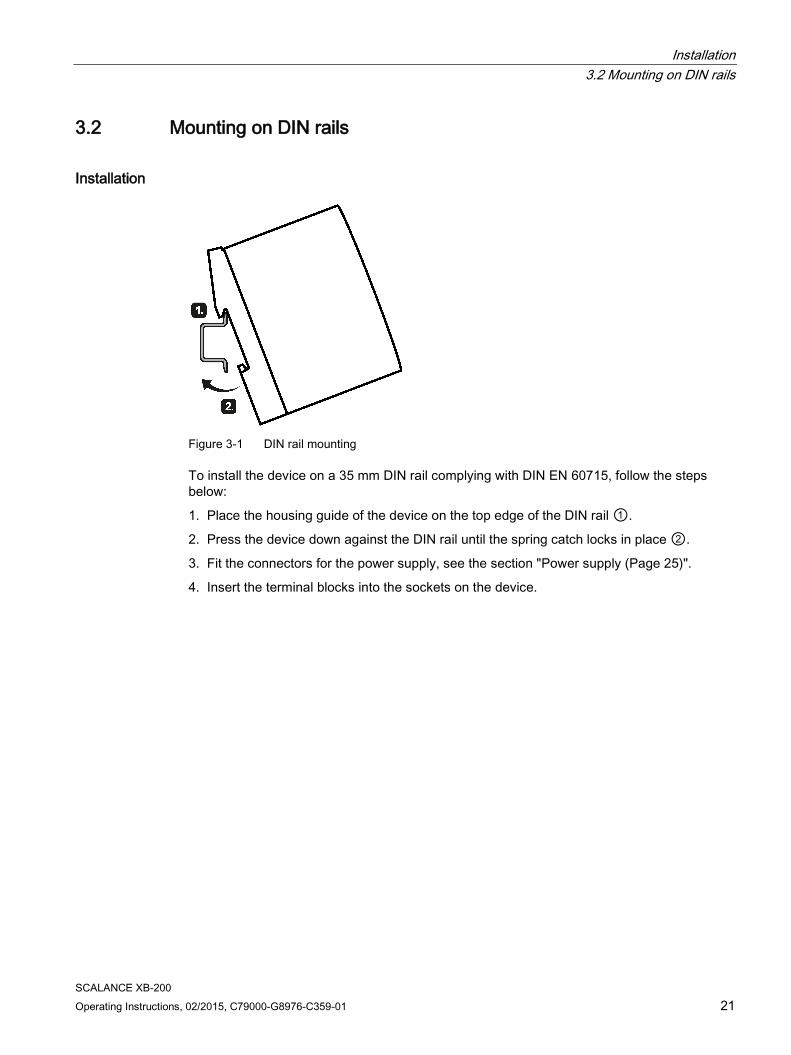
Installation
Figure 3-1 DIN rail mounting
To install the device on a 35 mm DIN rail complying with DIN EN 60715, follow the steps below:
1. Place the housing guide of the device on the top edge of the DIN rail ①.
2. Press the device down against the DIN rail until the spring catch locks in place ②.
3. Fit the connectors for the power supply, see the section "Power supply (Page 25)".
4. Insert the terminal blocks into the sockets on the device.

Installation 3.2 Mounting on DIN rails
SCALANCE XB-200 22 Operating Instructions, 02/2015, C79000-G8976-C359-01
Removal
Figure 3-2 Removing from a DIN rail
To remove the device from a DIN rail, follow the steps below:
1. Disconnect all connected cables.
2. Release the DIN rail locking mechanism by pressing down on the release button ①.
3. Pull the lower part of the device away from the DIN rail ②.
SCALANCE XB-200 Operating Instructions, 02/2015, C79000-G8976-C359-01 23
Connecting up 4 4.1 Safety when connecting up
Safety notices When connecting up the device, keep to the safety notices listed below.
WARNING
The equipment is designed for operation with Safety Extra-Low Voltage (SELV) by a Limited Power Source (LPS).
This means that only SELV / LPS complying with IEC 60950-1 / EN 60950-1 / VDE 0805-1 must be connected to the power supply terminals. The power supply unit for the equipment power supply must comply with NEC Class 2, as described by the National Electrical Code (r) (ANSI / NFPA 70).
If the equipment is connected to a redundant power supply (two separate power supplies), both must meet these requirements.
Safety notices on use in hazardous areas
General safety notices relating to protection against explosion
WARNING
EXPLOSION HAZARD
DO NOT CONNECT OR DISCONNECT EQUIPMENT WHEN A FLAMMABLE OR COMBUSTIBLE ATMOSPHERE IS PRESENT.
Safety notices when using the device according to Hazardous Locations (HazLoc)
If you use the device under HazLoc conditions you must also keep to the following safety notices in addition to the general safety notices for protection against explosion:
WARNING
EXPLOSION HAZARD
DO NOT DISCONNECT WHILE CIRCUIT IS LIVE UNLESS AREA IS KNOWN TO BE NON-HAZARDOUS.

Connecting up 4.1 Safety when connecting up
SCALANCE XB-200 24 Operating Instructions, 02/2015, C79000-G8976-C359-01
Safety notices when using the device according to ATEX and IECEx
If you use the device under ATEX or IECEx conditions you must also keep to the following safety notices in addition to the general safety notices for protection against explosion:
WARNING
Take measures to prevent transient voltage surges of more than 40% of the rated voltage. This is the case if you only operate devices with SELV (safety extra-low voltage).
In areas subject to the NEC or CEC:
WARNING
Safety notice for connectors with LAN (Local Area Network) marking
A LAN or LAN segment, with all its associated interconnected equipment, shall be entirely contained within a single low-voltage power distribution and within a single building. The LAN is considered to be in an "environment A" according to IEEE802.3 or "environment 0" according to IEC TR 62102, respectively. Never connect directly to TNV-circuits (Telephone Network) or WAN (Wide Area Network).
Connecting up 4.2 Power supply
SCALANCE XB-200 Operating Instructions, 02/2015, C79000-G8976-C359-01 25
4.2 Power supply
Notes on the power supply
WARNING
Incorrect power supply
Never operate the device with AC voltage or DC voltage higher than 32 V DC.
CAUTION
Damage to the device due to overvoltage
The connector of the external power supply is not protected against strong electromagnetic pulses that can, for example, result from lightning strikes or switching large loads.
One of the tests used to attest the immunity of devices of the SCALANCE CB-200 IE switches to electromagnetic interference is the "surge immunity test" according to EN61000-4-5. This test requires overvoltage protection for the power supply lines. A suitable device is, for example, the Dehn Blitzductor BVT AVD 24, article number 918 422 or a comparable protective element.
Manufacturer: DEHN+SOEHNE GmbH+Co.KG, Hans-Dehn-Str.1, Postfach 1640, D92306 Neumarkt, Germany
Operate the SCALANCE XB-200 with suitable overvoltage protection.
Information on the power supply ● The power supply is connected using a 3-pin plug-in terminal block (spring-loaded
terminal). The terminal block ships with the device and can also be ordered as a spare part.
● The power supply can be connected redundantly. Both inputs are isolated. There is no distribution of load.
● The power supply is connected over a high resistance with the enclosure to allow an ungrounded set up. The two power inputs are non-floating.
● To wire up the power connector, use a copper cable of category 24-16 AWG or a cable with a cross-section of 0.25 to 1.5 mm².
● To wire up the functional ground, use a copper cable of category 20-16 AWG or a cable with a cross-section of 0.75 to 1.5 mm².
Connecting up 4.2 Power supply
SCALANCE XB-200 26 Operating Instructions, 02/2015, C79000-G8976-C359-01
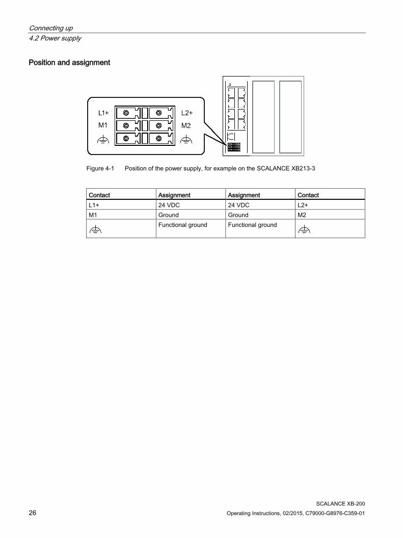
Position and assignment
Figure 4-1 Position of the power supply, for example on the SCALANCE XB213-3
Contact Assignment Assignment Contact L1+ 24 VDC 24 VDC L2+ M1 Ground Ground M2
Functional ground Functional ground
Connecting up 4.3 Serial interface
SCALANCE XB-200 Operating Instructions, 02/2015, C79000-G8976-C359-01 27
4.3 Serial interface
Information on the serial interface ● Via the serial interface (RJ-12 jack), you can access the CLI of the device directly via an
RS-232 connection (115200 8N1) without assigning an IP address.
● Access to the device is also possible independent of the Ethernet ports.
● To connect the serial interface to the PC, you require a cable with an RJ-11 plug and 9-pin D-sub female connector. You can order the connecting cable for the serial interface as an accessory.
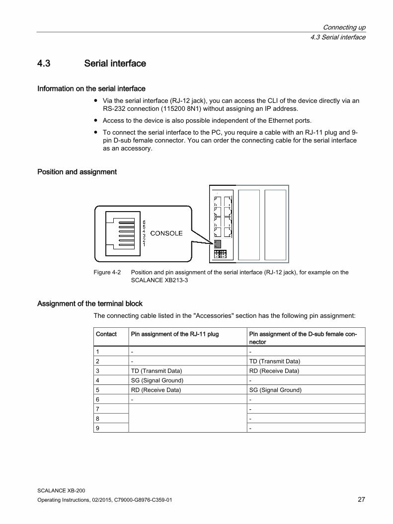
Position and assignment
Figure 4-2 Position and pin assignment of the serial interface (RJ-12 jack), for example on the
SCALANCE XB213-3
Assignment of the terminal block The connecting cable listed in the "Accessories" section has the following pin assignment: Contact Pin assignment of the RJ-11 plug Pin assignment of the D-sub female con-
nector 1 - - 2 - TD (Transmit Data) 3 TD (Transmit Data) RD (Receive Data) 4 SG (Signal Ground) - 5 RD (Receive Data) SG (Signal Ground) 6 - - 7 - 8 - 9 -

Connecting up 4.4 Functional ground
SCALANCE XB-200 28 Operating Instructions, 02/2015, C79000-G8976-C359-01
Note Pin assignment of the RJ-12 jack on the device
The RJ-12 jack on the device has a pinout to match the RJ-11 plug of the connecting cable mentioned above.
4.4 Functional ground EMC disturbances are diverted to ground via the functional ground. This ensures the immunity of the data transmission.
The functional ground must be implemented with low impedance. The connection of the functional ground must be established directly on the mounting plate or the DIN rail terminal.
The SCALANCE XB-200 has a terminal for functional ground, refer to the section "Power supply (Page 25)". Keep to the specified cross-sectional area for the functional ground.
The terminal is identified by the following symbol for the functional ground .
Follow the steps below to connect the functional ground:
1. Connect the terminal of the SCALANCE XB-200 with as short a cable as possible ≤ 150 mm and with the required cross-sectional area to a grounded part of the system (DIN rail).
2. Connect the DIN rail with the ground of the system.
Protective/functional ground The connection of the reference potential surface with the protective ground system is normally in the cabinet close to the power feed-in. This ground conducts fault currents to ground safely and according DIN/VDE 0100 is a protective ground to protect people, animals and property from too high contact voltages.
Apart from the protective ground, there is functional grounding in the cabinet. According to EN60204-1 (DIN/VDE 0113 T1) electrical circuits must be grounded. The chassis (0 V) is grounded at one defined point. Here, once again the grounding is implemented with the lowest leakage resistance to ground in the vicinity of the power feed-in.
With automation components, functional ground also ensures interference-free operation of a controller. Via the functional ground, interference currents coupled in via the connecting cables are discharged to ground.

SCALANCE XB-200 Operating Instructions, 02/2015, C79000-G8976-C359-01 29
Upkeep and maintenance 5 5.1 Downloading new firmware using TFTP without WBM and CLI
Firmware The firmware is signed and encrypted. This ensures that only firmware created by Siemens can be downloaded to the device.
Procedure with Microsoft Windows Using TFTP, you can supply a device with new firmware even when it cannot be reached using WBM or CLI. This section explains the procedure based on the example of Microsoft Windows.
Follow the steps below to load new firmware using TFTP:
1. Turn off the power to the device.
2. Press the "RESET" button for example with a screwdriver and reconnect the power to the device while holding down the button.
3. Hold down the button until the red fault LED "F" starts to flash.
4. Release the button. The bootloader of the device waits in this status for a new firmware file that you can download by TFTP.
5. Connect a PC to any port of the device via an Ethernet cable.
6. Assign an IP address to the device using DHCP or the Primary Setup Tool.
7. Open a Windows command prompt and change to the directory where the file with the new firmware is located and then execute the following command : tftp -i <IP address> put <firmware file>
Note
You can enable TFTP in Microsoft Windows as follows:
"Control Panel" > "Programs and Features" > "Turn Windows features on or off" > "TFTP Client".
8. Once the firmware has been transferred completely to the device and validated, there is an automatic restart on the device. This may take several minutes.
Upkeep and maintenance 5.2 Restoring the factory settings
SCALANCE XB-200 30 Operating Instructions, 02/2015, C79000-G8976-C359-01
5.2 Restoring the factory settings Follow the steps below to reset the device parameters to the factory settings:
Note
When you reset the device parameters, all previously changed settings are lost.
1. Turn off the power to the device.
2. Press the "RESET" button for example with a screwdriver and reconnect the power to the device while holding down the button.
3. Hold down the button until the red fault LED "F" stops flashing after approximately 40 seconds and is permanently lit.
4. Release the button and wait until the fault LED "F" goes off.
The device starts automatically with the factory settings.
SCALANCE XB-200 Operating Instructions, 02/2015, C79000-G8976-C359-01 31
Technical specifications 6 6.1 Technical specifications of the SCALANCE XB208
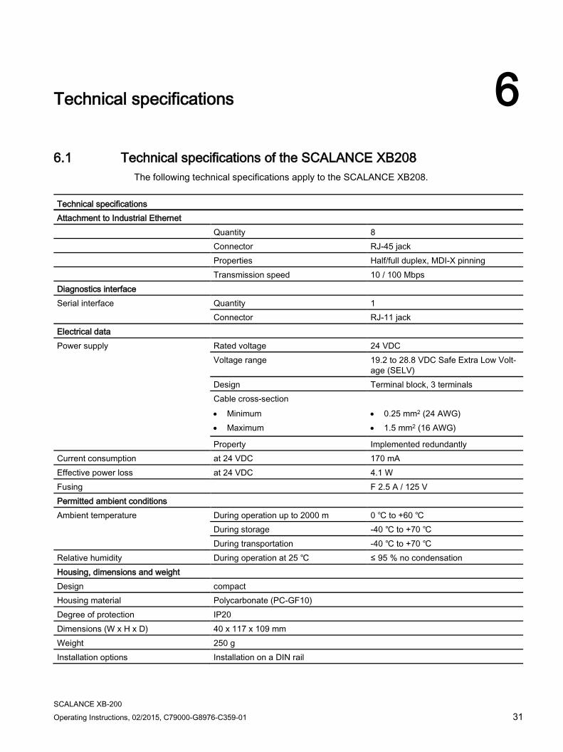
The following technical specifications apply to the SCALANCE XB208.
Technical specifications Attachment to Industrial Ethernet Quantity 8 Connector RJ-45 jack Properties Half/full duplex, MDI-X pinning Transmission speed 10 / 100 Mbps Diagnostics interface Serial interface Quantity 1
Connector RJ-11 jack Electrical data Power supply Rated voltage 24 VDC
Voltage range 19.2 to 28.8 VDC Safe Extra Low Volt-age (SELV)
Design Terminal block, 3 terminals Cable cross-section • Minimum • Maximum
• 0.25 mm2 (24 AWG) • 1.5 mm2 (16 AWG)
Property Implemented redundantly Current consumption at 24 VDC 170 mA Effective power loss at 24 VDC 4.1 W Fusing F 2.5 A / 125 V Permitted ambient conditions Ambient temperature During operation up to 2000 m 0 ℃ to +60 ℃
During storage -40 ℃ to +70 ℃ During transportation -40 ℃ to +70 ℃
Relative humidity During operation at 25 ℃ ≤ 95 % no condensation Housing, dimensions and weight Design compact Housing material Polycarbonate (PC-GF10) Degree of protection IP20 Dimensions (W x H x D) 40 x 117 x 109 mm Weight 250 g Installation options Installation on a DIN rail
Technical specifications 6.1 Technical specifications of the SCALANCE XB208
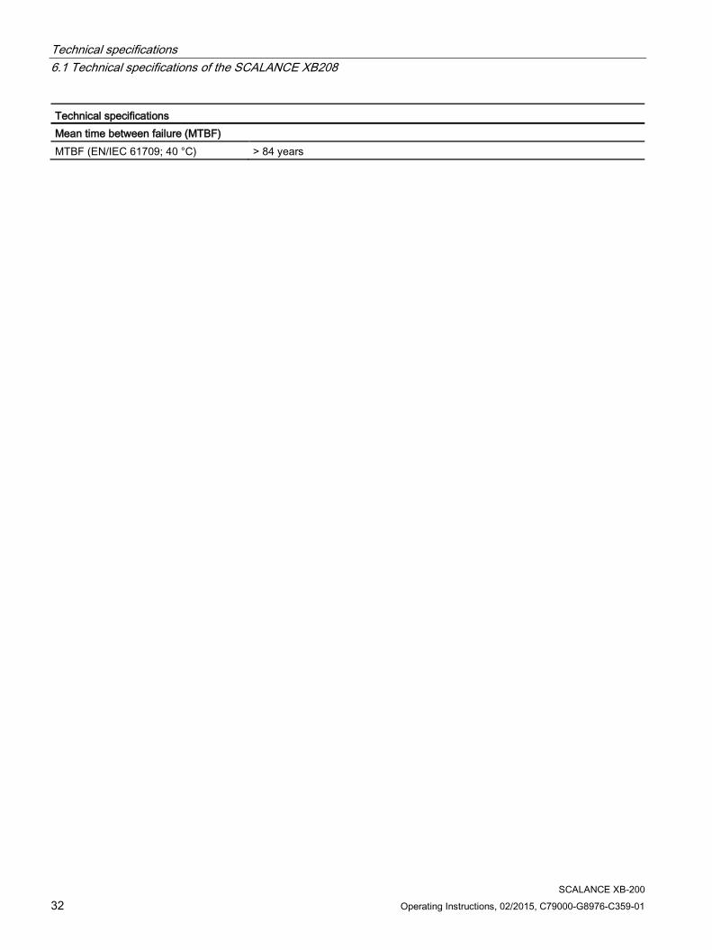
SCALANCE XB-200 32 Operating Instructions, 02/2015, C79000-G8976-C359-01
Technical specifications Mean time between failure (MTBF) MTBF (EN/IEC 61709; 40 °C) > 84 years

Technical specifications 6.2 Technical specifications of the SCALANCE XB205-3 (SC)
SCALANCE XB-200 Operating Instructions, 02/2015, C79000-G8976-C359-01 33
6.2 Technical specifications of the SCALANCE XB205-3 (SC) The following technical specifications apply to the SCALANCE XB205-3 (SC).
Technical specifications Attachment to Industrial Ethernet Electrical connectors Quantity 5
Connector RJ-45 jack Properties Half/full duplex, MDI-X pinning Transmission speed 10 / 100 Mbps
Optical connectors Quantity 3 Connector SC socket Properties Full duplex acc. to 100Base-FX Transmission speed 100 Mbps Cable type Multimode glass FO cable Transmitter output (optical) • Minimum • Maximum
• -19 dBm • -14 dBm
Receiver input • Sensitivity min. • Input power max.
• -34 dBm • -3 dBm
Cable cross-section • 50/125 μm • 62.5/125 μm
Cable length • 0 ... 5 km • 0 ... 5 km
Attenuation • ≤ 1 dB/km at 1310 nm; 1200 MHz * km • ≤ 1 dB/km at 1310 nm; 1200 MHz * km
Diagnostics interface Serial interface Quantity 1
Connector RJ-11 jack Electrical data Power supply Rated voltage 24 VDC
Voltage range 19.2 to 28.8 VDC Safe Extra Low Voltage (SELV)
Design Terminal block, 3 terminals Cable cross-section • Minimum • Maximum
• 0.25 mm2 (24 AWG) • 1.5 mm2 (16 AWG)
Properties Implemented redundantly Current consumption at 24 VDC 300 mA Effective power loss at 24 VDC 7.2 W Fusing F 2.5 A / 125 V

Technical specifications 6.2 Technical specifications of the SCALANCE XB205-3 (SC)
SCALANCE XB-200 34 Operating Instructions, 02/2015, C79000-G8976-C359-01
Technical specifications Permitted ambient conditions Ambient temperature During operation up to 2000 m 0 ℃ to +60 ℃
During storage -40 ℃ to +70 ℃ During transportation -40 ℃ to +70 ℃
Relative humidity During operation at 25 ℃ ≤ 95 % no condensation Housing, dimensions and weight Design compact Housing material Polycarbonate (PC-GF10) Degree of protection IP20 Dimensions (W x H x D) 80 x 117 x 109 mm Weight 350 g Installation options Installation on a DIN rail Mean time between failure (MTBF) MTBF (EN/IEC 61709; 40 °C) > 55 years

Technical specifications 6.3 Technical specifications of the SCALANCE XB205-3LD (SC)
SCALANCE XB-200 Operating Instructions, 02/2015, C79000-G8976-C359-01 35
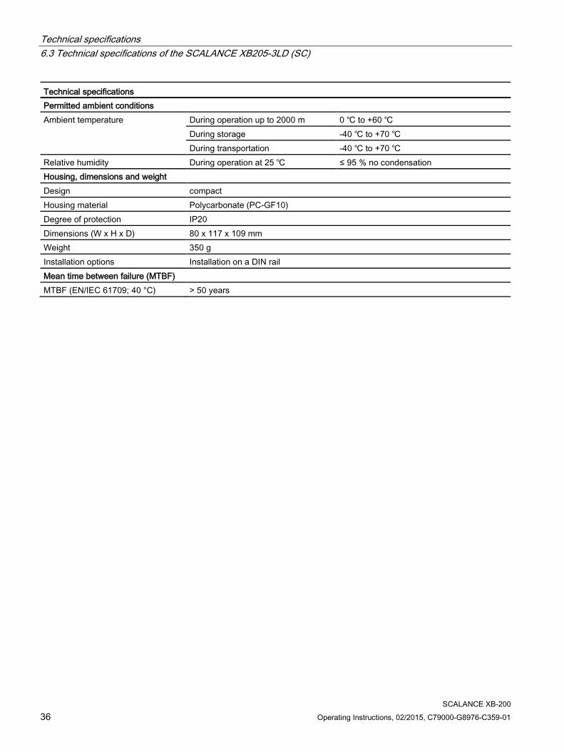
6.3 Technical specifications of the SCALANCE XB205-3LD (SC) The following technical specifications apply to the SCALANCE XB205-3LD (SC).
Technical specifications Attachment to Industrial Ethernet Electrical connectors Quantity 5
Connector RJ-45 jack Properties Half/full duplex, MDI-X pinning Transmission speed 10 / 100 Mbps
Optical connectors Quantity 3 Connector SC socket Properties Full duplex acc. to 100Base-FX Transmission speed 100 Mbps Cable type Single mode glass FO cable Transmitter output (optical) • Minimum • Maximum
• -15 dBm • -8 dBm
Receiver input • Sensitivity min. • Input power max.
• -32 dBm • -3 dBm
Cable cross-section • 9/125 μm
Cable length • 0 to 26 km
Attenuation • ≤ 0.5 dB/km at 1310 nm
Diagnostics interface Serial interface Quantity 1
Connector RJ-11 jack Electrical data Power supply Rated voltage 24 VDC
Voltage range 19.2 to 28.8 VDC Safe Extra Low Voltage (SELV)
Design Terminal block, 3 terminals Cable cross-section • Minimum • Maximum
• 0.25 mm2 (24 AWG) • 1.5 mm2 (16 AWG)
Properties Implemented redundantly Current consumption at 24 VDC 290 mA Effective power loss at 24 VDC 7 W Fusing F 2.5 A / 125 V
Technical specifications 6.3 Technical specifications of the SCALANCE XB205-3LD (SC)
SCALANCE XB-200 36 Operating Instructions, 02/2015, C79000-G8976-C359-01
Technical specifications Permitted ambient conditions Ambient temperature During operation up to 2000 m 0 ℃ to +60 ℃
During storage -40 ℃ to +70 ℃ During transportation -40 ℃ to +70 ℃
Relative humidity During operation at 25 ℃ ≤ 95 % no condensation Housing, dimensions and weight Design compact Housing material Polycarbonate (PC-GF10) Degree of protection IP20 Dimensions (W x H x D) 80 x 117 x 109 mm Weight 350 g Installation options Installation on a DIN rail Mean time between failure (MTBF) MTBF (EN/IEC 61709; 40 °C) > 50 years

Technical specifications 6.4 Technical specifications of the SCALANCE XB205-3
SCALANCE XB-200 Operating Instructions, 02/2015, C79000-G8976-C359-01 37
6.4 Technical specifications of the SCALANCE XB205-3 The following technical specifications apply to the SCALANCE XB205-3.
Technical specifications Attachment to Industrial Ethernet Electrical connectors Quantity 5
Connector RJ-45 jack Properties Half/full duplex, MDI-X pinning Transmission speed 10 / 100 Mbps
Optical connectors Quantity 3 Connector ST(BFOC) socket Properties Full duplex acc. to 100Base-FX Transmission speed 100 Mbps Cable type Multimode glass FO cable Transmitter output (optical) • Minimum • Maximum
• -19 dBm • -14 dBm
Receiver input • Sensitivity min. • Input power max.
• -32 dBm • -3 dBm
Cable cross-section • 50/125 μm • 62.5/125 μm
Cable length • 0 ... 5 km • 0 ... 5 km
Attenuation • ≤ 1 dB/km at 1310 nm; 1200 MHz * km • ≤ 1 dB/km at 1310 nm; 1200 MHz * km
Diagnostics interface Serial interface Quantity 1
Connector RJ-11 jack Electrical data Power supply Rated voltage 24 VDC
Voltage range 19.2 to 28.8 VDC Safe Extra Low Voltage (SELV)
Design Terminal block, 3 terminals Cable cross-section • Minimum • Maximum
• 0.25 mm2 (24 AWG) • 1.5 mm2 (16 AWG)
Properties Implemented redundantly Current consumption at 24 VDC 300 mA Effective power loss at 24 VDC 7.2 W Fusing F 2.5 A / 125 V

Technical specifications 6.4 Technical specifications of the SCALANCE XB205-3
SCALANCE XB-200 38 Operating Instructions, 02/2015, C79000-G8976-C359-01
Technical specifications Permitted ambient conditions Ambient temperature During operation up to 2000 m 0 ℃ to +60 ℃
During storage -40 ℃ to +70 ℃ During transportation -40 ℃ to +70 ℃
Relative humidity During operation at 25 ℃ ≤ 95 % no condensation Housing, dimensions and weight Design compact Housing material Polycarbonate (PC-GF10) Degree of protection IP20 Dimensions (W x H x D) 80 x 117 x 109 mm Weight 350 g Installation options Installation on a DIN rail Mean time between failure (MTBF) MTBF (EN/IEC 61709; 40 °C) > 55 years
Technical specifications 6.5 Technical specifications of the SCALANCE XB216
SCALANCE XB-200 Operating Instructions, 02/2015, C79000-G8976-C359-01 39
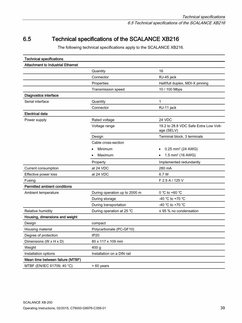
6.5 Technical specifications of the SCALANCE XB216 The following technical specifications apply to the SCALANCE XB216.
Technical specifications Attachment to Industrial Ethernet Quantity 16 Connector RJ-45 jack Properties Half/full duplex, MDI-X pinning Transmission speed 10 / 100 Mbps Diagnostics interface Serial interface Quantity 1
Connector RJ-11 jack Electrical data Power supply Rated voltage 24 VDC
Voltage range 19.2 to 28.8 VDC Safe Extra Low Volt-age (SELV)
Design Terminal block, 3 terminals Cable cross-section • Minimum • Maximum
• 0.25 mm2 (24 AWG) • 1.5 mm2 (16 AWG)
Property Implemented redundantly Current consumption at 24 VDC 280 mA Effective power loss at 24 VDC 6.7 W Fusing F 2.5 A / 125 V Permitted ambient conditions Ambient temperature During operation up to 2000 m 0 ℃ to +60 ℃
During storage -40 ℃ to +70 ℃ During transportation -40 ℃ to +70 ℃
Relative humidity During operation at 25 ℃ ≤ 95 % no condensation Housing, dimensions and weight Design compact Housing material Polycarbonate (PC-GF10) Degree of protection IP20 Dimensions (W x H x D) 80 x 117 x 109 mm Weight 400 g Installation options Installation on a DIN rail Mean time between failure (MTBF) MTBF (EN/IEC 61709; 40 °C) > 60 years

Technical specifications 6.6 Technical specifications of the SCALANCE XB213-3 (SC)
SCALANCE XB-200 40 Operating Instructions, 02/2015, C79000-G8976-C359-01
6.6 Technical specifications of the SCALANCE XB213-3 (SC) The following technical specifications apply to the SCALANCE XB213-3 (SC).
Technical specifications Attachment to Industrial Ethernet Electrical connectors Quantity 13
Connector RJ-45 jack Properties Half/full duplex, MDI-X pinning Transmission speed 10 / 100 Mbps
Optical connectors Quantity 3 Connector SC socket Properties Full duplex acc. to 100Base-FX Transmission speed 100 Mbps Cable type Multimode glass FO cable Transmitter output (optical) • Minimum • Maximum
• -19 dBm • -14 dBm
Receiver input • Sensitivity min. • Input power max.
• -34 dBm • -3 dBm
Cable cross-section • 50/125 μm • 62.5/125 μm
Cable length • 0 ... 5 km • 0 ... 5 km
Attenuation • ≤ 1 dB/km at 1310 nm; 1200 MHz * km • ≤ 1 dB/km at 1310 nm; 1200 MHz * km
Diagnostics interface Serial interface Quantity 1
Connector RJ-11 jack Electrical data Power supply Rated voltage 24 VDC
Voltage range 19.2 to 28.8 VDC Safe Extra Low Voltage (SELV)
Design Terminal block, 3 terminals Cable cross-section • Minimum • Maximum
• 0.25 mm2 (24 AWG) • 1.5 mm2 (16 AWG)
Properties Implemented redundantly Current consumption at 24 VDC 410 mA Effective power loss at 24 VDC 9.8 W Fusing F 2.5 A / 125 V

Technical specifications 6.6 Technical specifications of the SCALANCE XB213-3 (SC)
SCALANCE XB-200 Operating Instructions, 02/2015, C79000-G8976-C359-01 41
Technical specifications Permitted ambient conditions Ambient temperature During operation up to 2000 m 0 ℃ to +60 ℃
During storage -40 ℃ to +70 ℃ During transportation -40 ℃ to +70 ℃
Relative humidity During operation at 25 ℃ ≤ 95 % no condensation Housing, dimensions and weight Design compact Housing material Polycarbonate (PC-GF10) Degree of protection IP20 Dimensions (W x H x D) 120 x 117 x 109 mm Weight 500 g Installation options Installation on a DIN rail Mean time between failure (MTBF) MTBF (EN/IEC 61709; 40 °C) > 45 years
Technical specifications 6.7 Technical specifications of the SCALANCE XB213-3LD (SC)
SCALANCE XB-200 42 Operating Instructions, 02/2015, C79000-G8976-C359-01
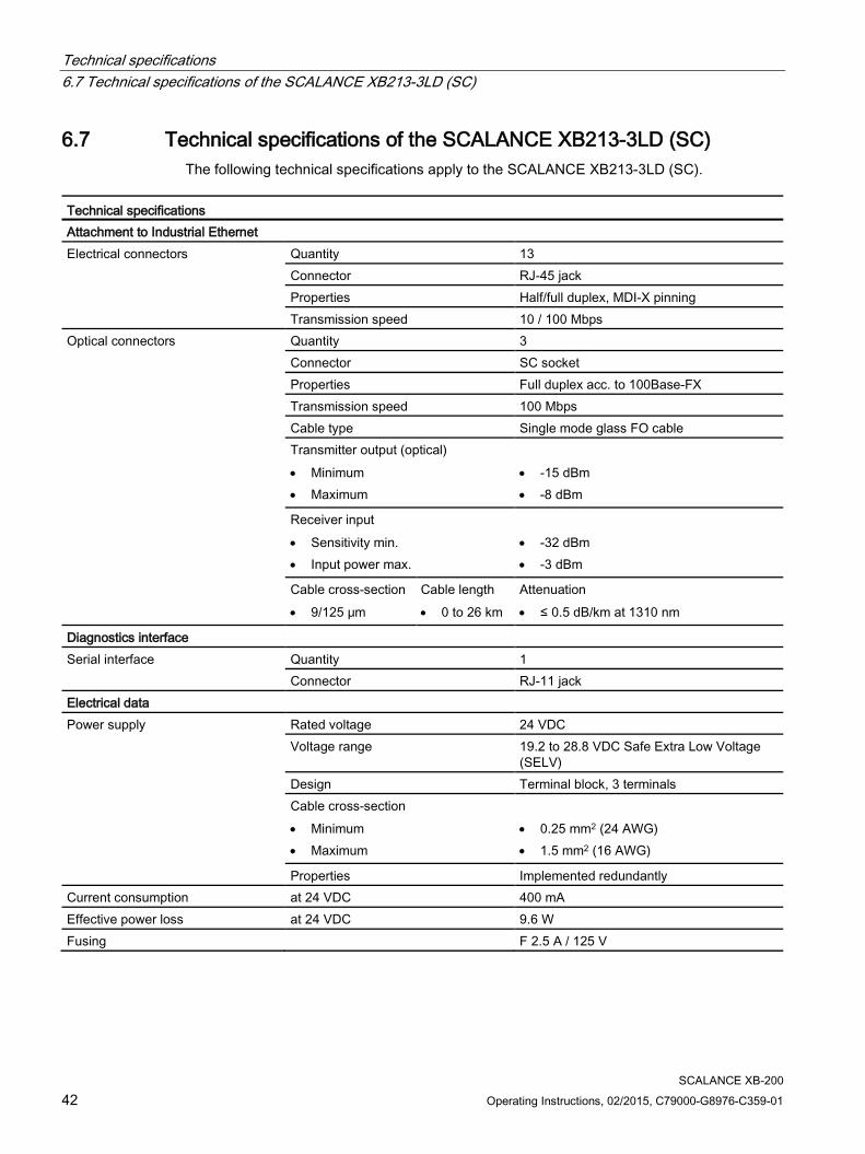
6.7 Technical specifications of the SCALANCE XB213-3LD (SC) The following technical specifications apply to the SCALANCE XB213-3LD (SC).
Technical specifications Attachment to Industrial Ethernet Electrical connectors Quantity 13
Connector RJ-45 jack Properties Half/full duplex, MDI-X pinning Transmission speed 10 / 100 Mbps
Optical connectors Quantity 3 Connector SC socket Properties Full duplex acc. to 100Base-FX Transmission speed 100 Mbps Cable type Single mode glass FO cable Transmitter output (optical) • Minimum • Maximum
• -15 dBm • -8 dBm
Receiver input • Sensitivity min. • Input power max.
• -32 dBm • -3 dBm
Cable cross-section • 9/125 μm
Cable length • 0 to 26 km
Attenuation • ≤ 0.5 dB/km at 1310 nm
Diagnostics interface Serial interface Quantity 1
Connector RJ-11 jack Electrical data Power supply Rated voltage 24 VDC
Voltage range 19.2 to 28.8 VDC Safe Extra Low Voltage (SELV)
Design Terminal block, 3 terminals Cable cross-section • Minimum • Maximum
• 0.25 mm2 (24 AWG) • 1.5 mm2 (16 AWG)
Properties Implemented redundantly Current consumption at 24 VDC 400 mA Effective power loss at 24 VDC 9.6 W Fusing F 2.5 A / 125 V
Technical specifications 6.7 Technical specifications of the SCALANCE XB213-3LD (SC)
SCALANCE XB-200 Operating Instructions, 02/2015, C79000-G8976-C359-01 43
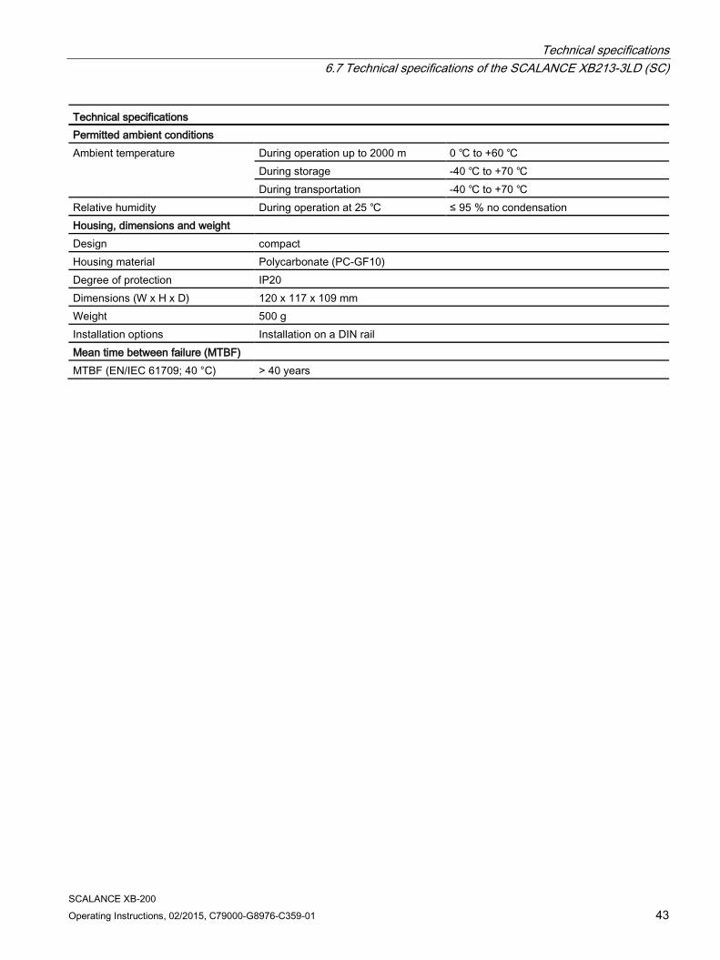
Technical specifications Permitted ambient conditions Ambient temperature During operation up to 2000 m 0 ℃ to +60 ℃
During storage -40 ℃ to +70 ℃ During transportation -40 ℃ to +70 ℃
Relative humidity During operation at 25 ℃ ≤ 95 % no condensation Housing, dimensions and weight Design compact Housing material Polycarbonate (PC-GF10) Degree of protection IP20 Dimensions (W x H x D) 120 x 117 x 109 mm Weight 500 g Installation options Installation on a DIN rail Mean time between failure (MTBF) MTBF (EN/IEC 61709; 40 °C) > 40 years
Technical specifications 6.8 Technical specifications of the SCALANCE XB213-3
SCALANCE XB-200 44 Operating Instructions, 02/2015, C79000-G8976-C359-01
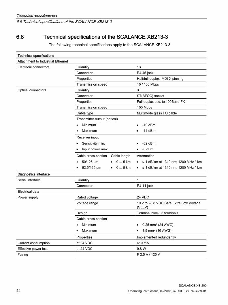
6.8 Technical specifications of the SCALANCE XB213-3 The following technical specifications apply to the SCALANCE XB213-3.
Technical specifications Attachment to Industrial Ethernet Electrical connectors Quantity 13
Connector RJ-45 jack Properties Half/full duplex, MDI-X pinning Transmission speed 10 / 100 Mbps
Optical connectors Quantity 3 Connector ST(BFOC) socket Properties Full duplex acc. to 100Base-FX Transmission speed 100 Mbps Cable type Multimode glass FO cable Transmitter output (optical) • Minimum • Maximum
• -19 dBm • -14 dBm
Receiver input • Sensitivity min. • Input power max.
• -32 dBm • -3 dBm
Cable cross-section • 50/125 μm • 62.5/125 μm
Cable length • 0 ... 5 km • 0 ... 5 km
Attenuation • ≤ 1 dB/km at 1310 nm; 1200 MHz * km • ≤ 1 dB/km at 1310 nm; 1200 MHz * km
Diagnostics interface Serial interface Quantity 1
Connector RJ-11 jack Electrical data Power supply Rated voltage 24 VDC
Voltage range 19.2 to 28.8 VDC Safe Extra Low Voltage (SELV)
Design Terminal block, 3 terminals Cable cross-section • Minimum • Maximum
• 0.25 mm2 (24 AWG) • 1.5 mm2 (16 AWG)
Properties Implemented redundantly Current consumption at 24 VDC 410 mA Effective power loss at 24 VDC 9.8 W Fusing F 2.5 A / 125 V

Technical specifications 6.8 Technical specifications of the SCALANCE XB213-3
SCALANCE XB-200 Operating Instructions, 02/2015, C79000-G8976-C359-01 45
Technical specifications Permitted ambient conditions Ambient temperature During operation up to 2000 m 0 ℃ to +60 ℃
During storage -40 ℃ to +70 ℃ During transportation -40 ℃ to +70 ℃
Relative humidity During operation at 25 ℃ ≤ 95 % no condensation Housing, dimensions and weight Design compact Housing material Polycarbonate (PC-GF10) Degree of protection IP20 Dimensions (W x H x D) 120 x 117 x 109 mm Weight 500 g Installation options Installation on a DIN rail Mean time between failure (MTBF) MTBF (EN/IEC 61709; 40 °C) > 45 years

Technical specifications 6.9 Cable lengths
SCALANCE XB-200 46 Operating Instructions, 02/2015, C79000-G8976-C359-01
6.9 Cable lengths The following technical specifications apply to the following devices:
● SCALANCE XB208
● SCALANCE XB205-3 (SC)
● SCALANCE XB205-3LD (SC)
● SCALANCE XB205-3
● SCALANCE XB216
● SCALANCE XB213-3 (SC)
● SCALANCE XB213-3LD (SC)
● SCALANCE XB213-3
Cable Permitted cable length IE TP torsion cable with IE FC Outlet RJ-45 + 10 m TP cord
0 to 45 m + 10 m TP cord
IE TP torsion cable with IE FC RJ-45 Plug 180
0 to 55 m
IE FC TP Marine / Trailing / Flexible cable with IE FC Outlet RJ-45 + 10 m TP cord
0 to 75 m + 10 m TP cord
IE FC TP Marine / Trailing / Flexible cable with IE FC RJ-45 Plug 180
0 to 85 m
IE FC TP standard cable with IE FC Outlet RJ-45 + 10 m TP cord
0 to 90 m + 10 m TP cord
IE FC TP standard cable with IE FC RJ-45 Plug 180
0 to 100 m

Technical specifications 6.10 Switching properties
SCALANCE XB-200 Operating Instructions, 02/2015, C79000-G8976-C359-01 47
6.10 Switching properties
The following technical specifications apply to the following devices:
● SCALANCE XB208
● SCALANCE XB205-3 (SC)
● SCALANCE XB205-3LD (SC)
● SCALANCE XB205-3
● SCALANCE XB216
● SCALANCE XB213-3 (SC)
● SCALANCE XB213-3LD (SC)
● SCALANCE XB213-3
Switching properties Aging time Can be configured (default value: 40 seconds) Max. number of learnable addresses
8192
Switching technique Store and forward Latency 5 microseconds Full wire speed switching:
Number of frames per second (at 100 Mbps) Frame length 148810 64 bytes 84459 128 bytes 45290 256 bytes 23496 512 bytes 11973 1024 bytes 9615 1280 bytes 8127 1518 bytes
Note
The number of SCALANCE XB-200 modules connected in a line influences the frame delay. When a frame passes through the switch, this is delayed by the store-and-forward function of the SCALANCE XB-200 by 10-130 microseconds (at 100 Mbps).

Technical specifications 6.10 Switching properties
SCALANCE XB-200 48 Operating Instructions, 02/2015, C79000-G8976-C359-01

SCALANCE XB-200 Operating Instructions, 02/2015, C79000-G8976-C359-01 49
Dimension drawings 7
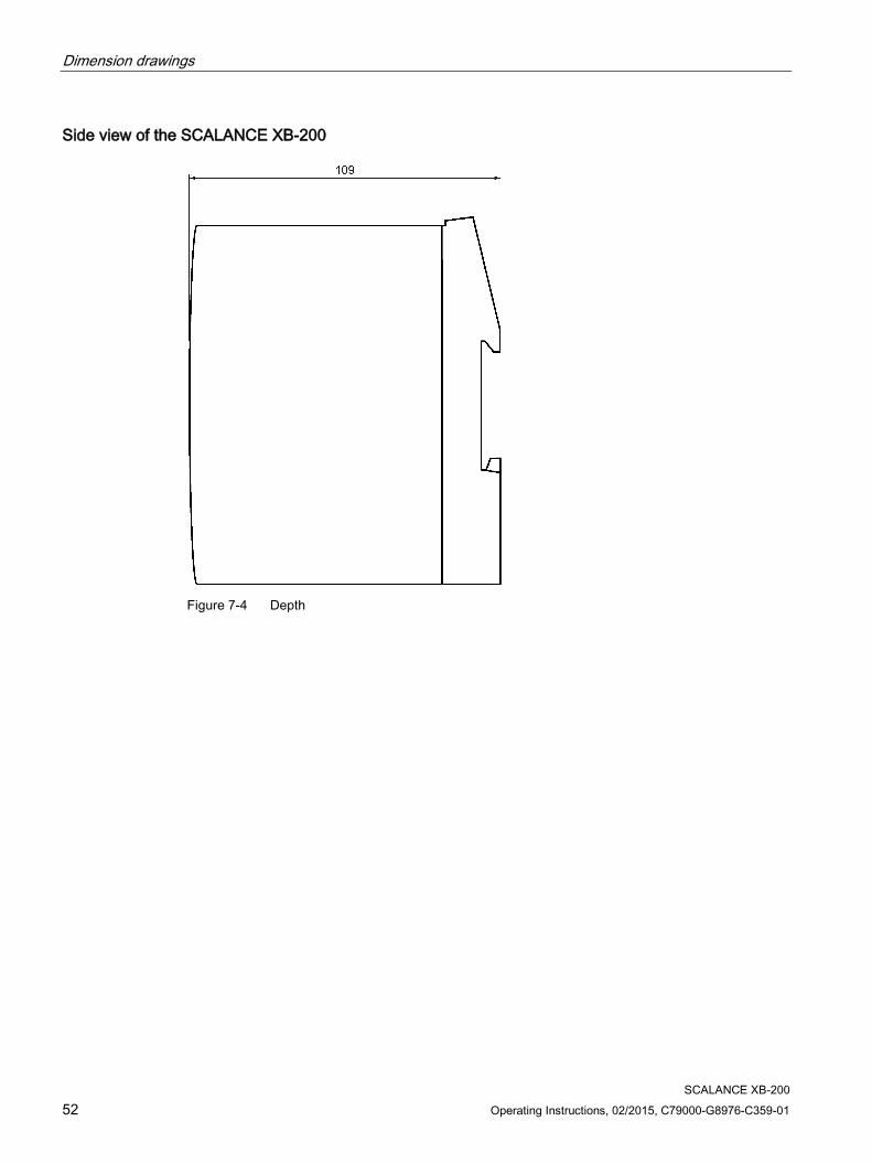
Note
Dimensions are specified in mm.
Front view of the SCALANCE XB208
Figure 7-1 Width and height

Dimension drawings
SCALANCE XB-200 50 Operating Instructions, 02/2015, C79000-G8976-C359-01
Front view of the SCALANCE XB205-3 (SC), XB205-3LD (SC), XB205-3 and XB216
Figure 7-2 Width and height based on the example of the SCALANCE XB205-3
Dimension drawings
SCALANCE XB-200 Operating Instructions, 02/2015, C79000-G8976-C359-01 51
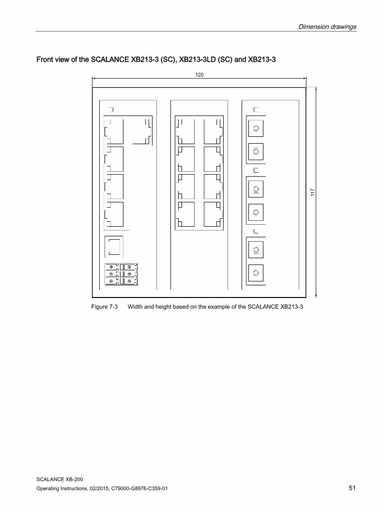
Front view of the SCALANCE XB213-3 (SC), XB213-3LD (SC) and XB213-3
Figure 7-3 Width and height based on the example of the SCALANCE XB213-3
Dimension drawings
SCALANCE XB-200 52 Operating Instructions, 02/2015, C79000-G8976-C359-01
Side view of the SCALANCE XB-200
Figure 7-4 Depth

SCALANCE XB-200 Operating Instructions, 02/2015, C79000-G8976-C359-01 53
Approvals A
The SIMATIC NET products described in these Operating Instructions have the approvals listed below.
Note Issued approvals on the type plate of the device
The specified approvals apply only when the corresponding mark is printed on the product. You can check which of the following approvals have been granted for your product by the markings on the type plate.
Current approvals on the Internet You will also find the current approvals for the product on the Internet pages of Siemens Industry Online Support under the following entry ID:
134200 (http://support.automation.siemens.com/WW/view/en/33118389/134200) → "Entry list" tab, entry type "Certificates"
EC directives SIMATIC NET products meet the requirements and aims of the following EC directives.
EMC directive (electromagnetic compatibility) The SIMATIC NET products described in these operating instructions meet the requirements of EC directive 2004/108/EC "Electromagnetic Compatibility" for the following areas of application: Field of application Requirements
Emission Immunity to interference Industry EN 61000-6-4 : 2007 EN 61000-6-2 : 2005
WARNING
Personal injury and property damage can occur
The installation of expansions that are not approved for SIMATIC NET products or their target systems may violate the requirements and regulations for safety and electromagnetic compatibility.
Only use expansions that are approved for the system.

Approvals
SCALANCE XB-200 54 Operating Instructions, 02/2015, C79000-G8976-C359-01
● Keep to the installation guidelines The devices meet the requirements if you adhere to the installation and safety instructions contained in this documentation and in the following documentation when installing and operating the devices.
● You can always find the latest documentation on the Internet The current descriptions of the currently available products can always be found on the Internet under the specified entry IDs/Internet pages:
– "Industrial Ethernet / PROFINET Industrial Ethernet" System Manual
– "Industrial Ethernet / PROFINET - Passive network components" System Manual
You will find information on the system manuals in the section "Introduction (Page 3)", in "Further documentation".
– "EMC Installation Guidelines" configuration manual
60612658 (http://support.automation.siemens.com/WW/view/en/60612658)
● Working on the device To protect the device from electrostatic discharge, personnel must first discharge any electrostatic charge from their body before touching the device.
Note
The test was performed with a device and a connected communications partner that also meets the requirements of the standards listed above.
When operating the device with a communications partner that does not comply with these standards, adherence to the corresponding values cannot be guaranteed.
Safety of electrical equipment In the version put into circulation by Siemens AG, the SIMATIC NET products described in these Operating Instructions conform to the regulations of the following European directive:
● EN 60950-1 Information technology equipment - Safety - Part 1: General requirements

Approvals
SCALANCE XB-200 Operating Instructions, 02/2015, C79000-G8976-C359-01 55
ATEX (explosion protection directive)
WARNING
When using SIMATIC NET products in hazardous area zone 2, make absolutely sure that the associated conditions in the following document are adhered to:
"SIMATIC NET Product Information Use of subasseblies/modules in a Zone 2 Hazardous Area".
You will find this document • on the data medium that ships with some devices. • on the Internet pages of Siemens Industry Online Support
(http://support.automation.siemens.com/WW/view/en).
Enter the document identification number C234 as the search term.
SIMATIC NET products meet the requirements of the EC directive:94/9/EC "Equipment and Protective Devices for Use in Potentially Explosive Atmospheres".
ATEX classification:
II 3 G Ex nA IIC T4 Gc
KEMA 07ATEX0145 X
The products meet the requirements of the following standards:
● EN 60079-15: 2010 (electrical apparatus for potentially explosive atmospheres; Type of protection "n")
● EN 60079-0: 2009 (Explosive atmospheres - Part 0: Equipment - General requirements)
IECEx The SIMATIC NET products meet the requirements of explosion protection according to IECEx.
IECEx classification:
Ex nA IIC T4 Gc
DEK 14.0025X
The products meet the requirements of the following standards:
● IEC 60079-15 : 2010 (Explosive atmospheres - Part 15: Equipment protection by type of protection "n"
● IEC 60079-0 : 2011 (Explosive atmospheres - Part 0: Equipment - General requirements)

Approvals
SCALANCE XB-200 56 Operating Instructions, 02/2015, C79000-G8976-C359-01
FM The product meets the requirements of the standards:
● Factory Mutual Approval Standard Class Number 3611
● FM Hazardous (Classified) Location Electrical Equipment: Non Incendive / Class I / Division 2 / Groups A,B,C,D / T4 and Non Incendive / Class I / Zone 2 / Group IIC / T4
RCM The product meets the requirements of the AS/NZS 2064 standard (Class A).
KC (Korean Standard) The products meet the requirements of the "Korean Standard".
cULus Approval for Information Technology Equipment cULus Listed I. T. E.
Underwriters Laboratories Inc. complying with
● UL 60950-1 (Information Technology Equipment)
● CSA C22.2 No. 60950-1-03
Report no. E115352
cULus Approval Hazardous Location cULus Listed I. T. E. FOR HAZ. LOC.
Underwriters Laboratories Inc. complying with
● UL 60950-1 (Information Technology Equipment)
● ANSI/ISA 12.12.01-2007
● CSA C22.2 No. 213-M1987
Approved for use in Cl. 1, Div. 2, GP A, B, C, D T4 Cl. 1, Zone 2, GP IIC T4
Report no. E240480
EU declaration of conformity You will find EC declaration of conformity for these products on the Internet pages of Siemens Industry Online Support (http://support.automation.siemens.com/WW/view/en/33118389/134200).

Approvals
SCALANCE XB-200 Operating Instructions, 02/2015, C79000-G8976-C359-01 57
FDA and IEC marks The following devices meet the FDA and IEC requirements listed below:
Device CLASS 1 LASER Product CLASS 1 LED Product SCALANCE XB208 - - SCALANCE XB205-3 (SC) - ● SCALANCE XB205-3LD (SC) ● - SCALANCE XB205-3 - ● SCALANCE XB216 - - SCALANCE XB213-3 (SC) - ● SCALANCE XB213-3LD (SC) ● - SCALANCE XB213-3 - ●
Figure A-1 FDA and IEC approvals
Mechanical stability (in operation) Device
IEC 60068-2-27 shock IEC 60068-2-6 vibration
15 g, 11 ms duration 6 shocks per axis
10 - 58 Hz: 0.075 mm 85 - 150 Hz: 1 g 1 octave/min, 20 sweeps
SCALANCE XB208 ● ● SCALANCE XB205-3 (SC) ● ● SCALANCE XB205-3LD (SC) ● ● SCALANCE XB205-3 ● ● SCALANCE XB216 ● ● SCALANCE XB213-3 (SC) ● ● SCALANCE XB213-3LD (SC) ● ● SCALANCE XB213-3 ● ●

Approvals
SCALANCE XB-200 58 Operating Instructions, 02/2015, C79000-G8976-C359-01

SCALANCE XB-200 Operating Instructions, 02/2015, C79000-G8976-C359-01 59
Index
A Accessories, 12 Ambient temperature, 31, 34, 36, 38, 39, 41, 43, 45 Article numbers, 11 Attachment to Industrial Ethernet, 31, 33, 35, 37, 39, 40, 42, 44
C CLI, 27, 29 Command Line Interface, 27, 29 Components of the product, 12 Connecting up
Grounding, 28
D Dimensions, 31, 34, 36, 38, 39, 41, 43, 45
E Electrical data, 31, 33, 35, 37, 39, 40, 42, 44 Environmental conditions, 31, 34, 36, 38, 39, 41, 43, 45
F Factory defaults, 16 Fault LED, 13, 14, 15 Firmware, 29
G Glossary, 5 Grounding, 13, 14, 15, 28
H Housing, 31, 34, 36, 38, 39, 41, 43, 45
I Installation, 31, 34, 36, 38, 39, 41, 43, 45
Installation on a DIN rail, 21 Installation on a DIN rail, 21
L LED displays, 17
Fault LED, 17 Port LEDs, 17
M MTBF, 32, 34, 36, 38, 39, 41, 43, 45
P Permitted ambient conditions, 31, 34, 36, 38, 39, 41, 43, 45 Power supply, 13, 14, 15, 25
R RESET button, 13, 14, 15, 16, 29 Reset device, 16
S Safety notices
for installation, 19 general, 9 Use in hazardous areas, 9, 19, 23 when connecting up, 23
Serial interface, 13, 14, 15, 27 SIMATIC NET glossary, 5 SIMATIC NET manual, 5 Spring-loaded terminal, 25 System manual, 4, 20, 54
W WBM, 29 Web Based Management, 29

Index
SCALANCE XB-200 60 Operating Instructions, 02/2015, C79000-G8976-C359-01
Weight, 31, 34, 36, 38, 39, 41, 43, 45