
Scalable Control System Freelance 2000€¦ · Freelance 800F AC 800F Data Sheet Data Sheet...
24
Freelance 800F AC 800F Data Sheet Data Sheet Description Features Control IT is the evolution of control systems into Industrial IT : Hardware and software components seamlessly integrate process- oriented information into true open applications, improving process control using worldwide-accepted industry standards. Scalable and platform independent products show the evolution path into the IT environment by enhancing your installation. AC 800F opens up the flexibility of Fieldbus technology to the user. The AC 800F collects and processes diagnostic and process data from four Fieldbus lines, which may be of dif- ferent types. It does this in addition to the tasks of a “conventional” process station. The AC 800F is available in two versions: • 4 MB static RAM, 4 MB EPROM • 16 MB synchronous dynamic RAM, 8 MB EPROM Up to 4 (different) fieldbus modules can be plugged into the AC 800F. The communication with other controllers runs via Ethernet. The AC 800F optionally provides several levels of redundancy: • device redundancy with 2 AC 800F • power supply redundancy (24 V DC) • Ethernet communication redundancy (standard) • Cable redundancy for Profibus DP, requires external equipment (RLM01) The data protection is made via battery back-up by Ethernet or battery modules with appropriate functionality. • Process Station with integrated fieldbus capability • 4 high-speed fieldbus lines • Supports different fieldbus types, even simultaneously: PROFIBUS-DP, up to 12 MBd Modbus CAN Foundation Fieldbus H1 (with LD800 HSE) • Easy engineering: fully integrated in Control Builder F • One unified database for field devices shared by the control level and the Human System Interface (HSI) • Module recognition with factory and op- erational parameters • Comprehensive diagnostics for proactive maintenance • Compact, rugged design • Front panel connectors • DIN Rail (C-rail) or wall mounting for easy installation • Ambient temperature 0-60 °C (32-140 °F) with temperature monitoring • EMC certification according to EN50082 • Certification: CE, NAMUR, CSA, UL, EN61000-6-2. June 2006 Gross Automation, 1725 South Johnson Road, New Berlin, WI 53146, www.ssacsales.com, 800-349-5827
Transcript of Scalable Control System Freelance 2000€¦ · Freelance 800F AC 800F Data Sheet Data Sheet...

Freelance 800FAC 800F
Data Sheet
Data Sheet
Description Features
ControlIT is the evolution of control systems into IndustrialIT:
Hardware and software components seamlessly integrate process-oriented information into true open applications, improving process control using worldwide-accepted industry standards. Scalable and platform independent products show the evolution path into the IT environment by enhancing your installation.
AC 800F opens up the flexibility of Fieldbus technology to the user. The AC 800F collects and processes diagnostic and process data from four Fieldbus lines, which may be of dif-ferent types. It does this in addition to the tasks of a “conventional” process station. The AC 800F is available in two versions:
• 4 MB static RAM, 4 MB EPROM
• 16 MB synchronous dynamic RAM, 8 MB EPROM
Up to 4 (different) fieldbus modules can be plugged into the AC 800F. The communication with other controllers runs via Ethernet. The AC 800F optionally provides several levels of redundancy: • device redundancy with 2 AC 800F
• power supply redundancy (24 V DC)
• Ethernet communication redundancy (standard)
• Cable redundancy for Profibus DP, requires external equipment (RLM01)
The data protection is made via battery back-up by Ethernet or battery modules with appropriate functionality.
• Process Station with integrated fieldbus capability
• 4 high-speed fieldbus lines
• Supports different fieldbus types, even simultaneously: PROFIBUS-DP, up to 12 MBd Modbus CAN Foundation Fieldbus H1 (with LD800 HSE)
• Easy engineering: fully integrated in Control Builder F
• One unified database for field devices shared by the control level and the Human System Interface (HSI)
• Module recognition with factory and op-erational parameters
• Comprehensive diagnostics for proactive maintenance
• Compact, rugged design
• Front panel connectors
• DIN Rail (C-rail) or wall mounting for easy installation
• Ambient temperature 0-60 °C (32-140 °F) with temperature monitoring
• EMC certification according to EN50082
• Certification: CE, NAMUR, CSA, UL, EN61000-6-2.
June 2006
Gross Automation, 1725 South Johnson Road, New Berlin, WI 53146, www.ssacsales.com, 800-349-5827

Redundancy conception AC 800F Controller Redundancy
Controller redundancy can be achieved by installing two AC 800F. To ensure quick and smooth takeover by the secon-dary AC 800F in case the primary AC 800F fails, a dedicated redundancy communications link through the second Ethernet module makes sure that both AC 800F are always synchro-nized. All inputs and outputs are designed to support redundant operation.
Profibus Line Redundancy
Using the Redundancy Link Module RLM 01 will do the conver-sion of one simple, non-redundant Profibus line into two recip-rocally redundant lines. You can position the Redundancy Link Module RLM 01 directly after a Profibus module (master), before a bus segment with several slaves or before an individual slave. PROFIBUS sta-tions with redundant couplers can be directly connected to the PROFIBUS set redundant by RLM 01. Stations with only one in-terface can be optionally assigned to the one or other line. For technical description dates of the Redundancy Link Module RLM 01 see document 3BDD011600R0201. An alternative solution to the Profibus line redundancy is to use a Fiber Optic Ring, for example with the OZD Profi 12M module from firm Hirschmann
AC800F Redundancy together with Profibus Line Re-dundancy
You can achieve both; controller redundancy and Profibus line redundancy by using two AC 800F with one RLM01 each. This topology combines the advantages of controller redundancy with the one of line redundancy as described in the above paragraphs.
Page 2 June 2006
Gross Automation, 1725 South Johnson Road, New Berlin, WI 53146, www.ssacsales.com, 800-349-5827
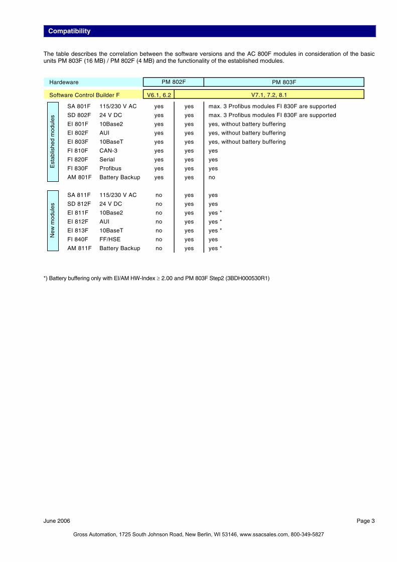
Compatibility The table describes the correlation between the software versions and the AC 800F modules in consideration of the basic units PM 803F (16 MB) / PM 802F (4 MB) and the functionality of the established modules.
Hardeware PM 803F
Software Control Builder F V6.1, 6.2
SA 801F 115/230 V AC yes yes max. 3 Profibus modules FI 830F are supported
SD 802F 24 V DC yes yes max. 3 Profibus modules FI 830F are supported
EI 801F 10Base2 yes yes yes, without battery buffering
EI 802F AUI yes yes yes, without battery buffering
EI 803F 10BaseT yes yes yes, without battery buffering
FI 810F CAN-3 yes yes yes
FI 820F Serial yes yes yes
FI 830F Profibus yes yes yes
AM 801F Battery Backup yes yes no
SA 811F 115/230 V AC no yes yes
SD 812F 24 V DC no yes yes
EI 811F 10Base2 no yes yes *
EI 812F AUI no yes yes *
EI 813F 10BaseT no yes yes *
FI 840F FF/HSE no yes yes
AM 811F Battery Backup no yes yes *
PM 802F
V7.1, 7.2, 8.1
Est
ablis
hed
mod
ules
New
mod
ules
*) Battery buffering only with EI/AM HW-Index ≥ 2.00 and PM 803F Step2 (3BDH000530R1)
June 2006 Page 3
Gross Automation, 1725 South Johnson Road, New Berlin, WI 53146, www.ssacsales.com, 800-349-5827

Basic Unit PM 802F /PM 803F Features
Page 4 June 2006
Super Scalar RISC microprocessor (up to 150 MIPS) 16 K internal CPU cache RAM RAM memory with error detection and correction
PM 802F: 4 MB static PM 803F: 16 MB synchronous dynamic
Flash-EPROM PM 802F: 4 MB, 32-bit words PM 803F: 8 MB, 32- bit words
EEPROM, serial, 16 Kbit Monitoring of the temperature inside the device Watchdog 4 slots for fieldbus modules 2 slots for Ethernet communications modules, 32-bit data
bus, 100 MBytes/s Battery backup incl. battery watchdog
Description The basic unit, PM 802F and respectively PM803F, cyclically scans signals from the fieldbus sensors via the corresponding fieldbus modules, processes these signals according the appli-cation programs installed by the user and sends appropriate signals to the fieldbus actuators via the fieldbus modules. Controller redundancy can be achieved by installing two AC 800F. To ensure quick and smooth takeover by the secon-dary AC 800F in case the primary AC 800F fails, a dedicated redundancy communications link through the second Ethernet module makes sure that both AC 800F are always synchro-nized. All inputs and outputs are designed to support redundant operation. Data communication between AC 800F, process and operator stations runs over the Ethernet system bus on the first Ethernet module. Data exchange with the engineering station is also car-ried via the system bus. Engineering station communications can involve new or updated configuration files being downloaded to the process stations, or information about the connected modules being reported back. When fieldbus mod-ules are installed or exchanged, the required configuration in-formation is automatically updated. Configuration and real-time process data is stored in RAM. To safeguard this data in case of power loss, the RAM power is backed up with batteries located either on the Ethernet modules or on battery modules. The PM 803F has more memory than the PM 802F and is therefor capable to handle larger projects. Due to increased memory size and different technology the buffering times were reduced.
202
239 164152
E1 E2 F1 F3F2 F4Slot P
Technical Data CPU Intel 80960HT25/75
32-bit RISC Super Scalar processor up to 150 MIPS
RAM PM802F:
4 MB static read/write memory battery back up PM 803F 16 Mbytes synchronous dynamic read/write memory, battery back up
I/O scan cycle time Selectable by configuration. Depends on
the capabilities of the fieldbus module Processing time for 1000 instructions < 1.0 ms for binary and 16 bit arithmetic
instructions < 2 ms for fixed point arithmetic instruc-
tions < 1.5 ms for 32 bit arithmetic instructions Power consumption: Basic unit only: PM 802F PM 803F
max. 6.3 W max. 7.8 W depending on CPU usage and cycle time
Power supply PM 802F PM 803F
115 - 230 V AC SA 801F SA 811F 2 x 24 V DC SD 802F SD 812F
Max. power output see power supply modules Weight 1.6 kg
max. 5 kg (fully assembled) Dimensions Width 239 mm, 9.4 inches
Height 202 mm, 8 inches Depth 164 mm, 6.5 inches
Gross Automation, 1725 South Johnson Road, New Berlin, WI 53146, www.ssacsales.com, 800-349-5827
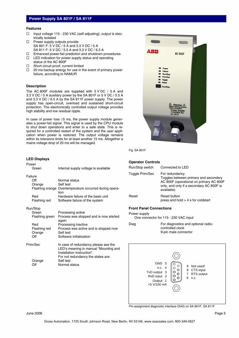
Power Supply SA 801F / SA 811F Features Input voltage 115 - 230 VAC (self adjusting), output is elec-
trically isolated Power supply outputs provide:
SA 801 F: 5 V DC / 5 A and 3.3 V DC / 5 A SA 811 F: 5 V DC / 5.5 A and 3.3 V DC / 6.5 A
Enhanced power-fail prediction and shutdown procedures LED indication for power supply status and operating
status of the AC 800F Short circuit proof, current limited 20 ms backup energy for use in the event of primary power
failure, according to NAMUR Description The AC 800F modules are supplied with 5 V DC / 5 A and 3.3 V DC / 5 A auxiliary power by the SA 801F or 5 V DC / 5.5 A and 3.3 V DC / 6.5 A by the SA 811F power supply. The power supply has open-circuit, overload and sustained short-circuit protection. The electronically controlled output voltage provides high stability and low residual ripple. In case of power loss ≥5 ms, the power supply module gener-ates a power-fail signal. This signal is used by the CPU module to shut down operations and enter to a safe state. This is re-quired for a controlled restart of the system and the user appli-cation when power is restored. The output voltage remains within its tolerance limits for at least another 15 ms. Altogether a mains voltage drop of 20 ms will be managed. LED Displays
Power Green Internal supply voltage is available Failure Off Normal status Orange Self test Flashing orange Overtemperature occurred during opera-
tion Red Hardware failure of the basic unit Flashing red Software failure of the system Run/Stop Green Processing active Flashing green Process was stopped and is now started
again Red Processing inactive Flashing red Process was active and is stopped now Orange Self test Off Software initialization Prim/Sec In case of redundancy please see the
LED’s meaning in manual “Mounting and Installation Instruction”. For not redundancy the states are:
Orange Self test Off Normal status
Operator Controls Run/Stop switch Connected to LED
Toggle Prim/Sec For redundancy. Toggles between primary and secondary AC 800F (operational on primary AC 800F only, and only if a secondary AC 800F is available)
Reset Reset button press and hold > 4 s for coldstart
Front Panel Connections Power supply One connector for 115 - 230 VAC input
Diag For diagnostics and optional radio-controlled clock 9-pin male connector
Fig. SA 801F
Output 1+5 V/100 mA
RxD input 2TxD output 3
n.c. 4GND 5
6 n.c.7 RTS output8 CTS input9 Not used!
Pin-assignment diagnostic interface DIAG on SA 801F, SA 811F
June 2006 Page 5
Gross Automation, 1725 South Johnson Road, New Berlin, WI 53146, www.ssacsales.com, 800-349-5827
Page 6 June 2006
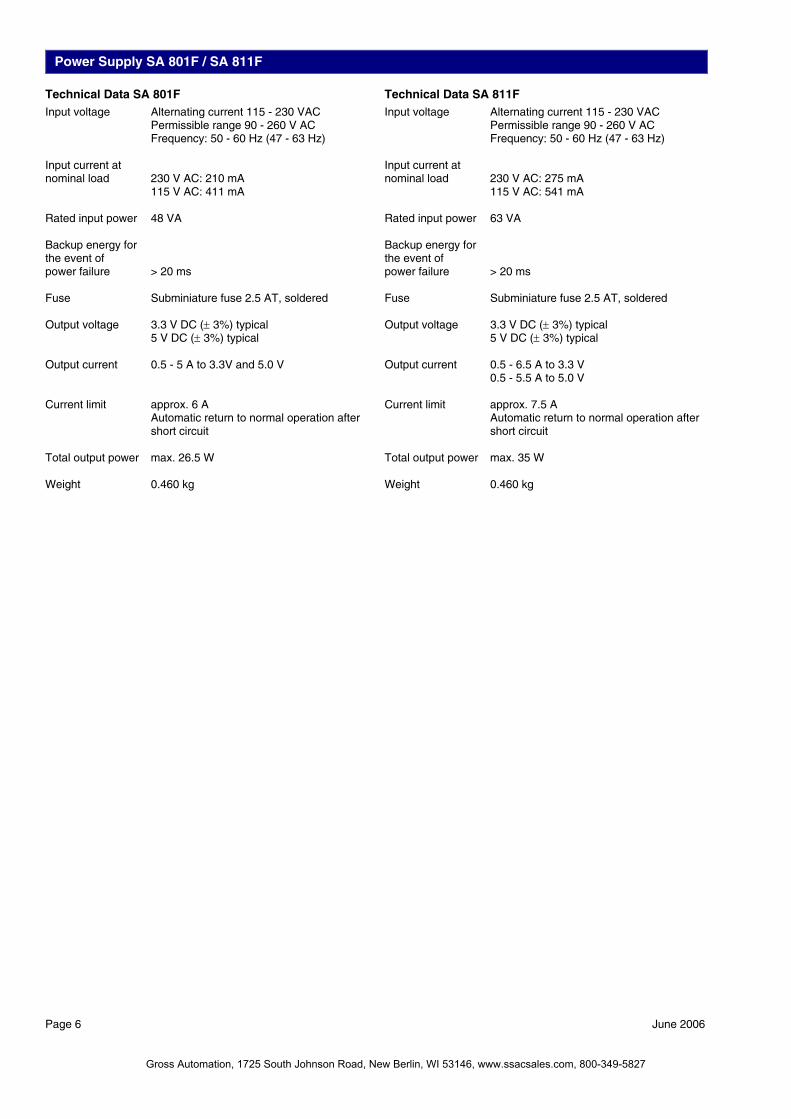
Power Supply SA 801F / SA 811F Technical Data SA 801F Input voltage Alternating current 115 - 230 VAC Permissible range 90 - 260 V AC
Frequency: 50 - 60 Hz (47 - 63 Hz) Input current at nominal load 230 V AC: 210 mA
115 V AC: 411 mA Rated input power 48 VA Backup energy for the event of power failure > 20 ms Fuse Subminiature fuse 2.5 AT, soldered Output voltage 3.3 V DC (± 3%) typical
5 V DC (± 3%) typical Output current 0.5 - 5 A to 3.3V and 5.0 V Current limit approx. 6 A
Automatic return to normal operation after short circuit
Total output power max. 26.5 W Weight 0.460 kg
Technical Data SA 811F Input voltage Alternating current 115 - 230 VAC Permissible range 90 - 260 V AC
Frequency: 50 - 60 Hz (47 - 63 Hz) Input current at nominal load 230 V AC: 275 mA
115 V AC: 541 mA Rated input power 63 VA Backup energy for the event of power failure > 20 ms Fuse Subminiature fuse 2.5 AT, soldered Output voltage 3.3 V DC (± 3%) typical
5 V DC (± 3%) typical Output current 0.5 - 6.5 A to 3.3 V
0.5 - 5.5 A to 5.0 V Current limit approx. 7.5 A
Automatic return to normal operation after short circuit
Total output power max. 35 W Weight 0.460 kg
Gross Automation, 1725 South Johnson Road, New Berlin, WI 53146, www.ssacsales.com, 800-349-5827

Power Supply SD 802F / SD 812F
Features Redundant input voltage 24 V DC, provides operation in
accordance with NAMUR Power supply outputs provide:
SD 802F: 5 V DC / 5 A and 3.3 V DC / 5 A SD 812F: 5 V DC / 5.5 A and 3.3 V DC / 6.5 A
Enhanced power-fail prediction and shutdown procedures LED indication for power supply status and operating
status of the AC 800F Short circuit proof, current limited 20 ms backup energy for use in the event of primary power
failure, according to NAMUR Description The AC 800F modules are supplied with 5 V DC / 5 A and 3.3 V DC / 5 A auxiliary power by the SD 802F power supply module, resp. with 5 V DC / 5.5 A and 3.3 V DC / 6.5 A by the SD 812F. The power supply has open-circuit, overload and sus-tained short-circuit protection. The electronically controlled out-put voltage provides high stability and low residual ripple. In case of power loss ≥ 5 ms, the power supply module gener-ates a power-fail signal. This signal is used by the CPU module to shut down operations and enter to a safe state. This is re-quired for a controlled restart of the system and the user appli-cation when power is restored. The output voltage remains within its tolerance limits for at least another 15 ms. Altogether an input voltage drop of 20 ms will be managed. LED Displays
Power Green Internal supply voltage is available Failure Off Normal status Orange Self test Flashing orange Overtemperature occurred during opera-
tion Red Hardware failure of the basic unit Flashing red Software failure of the system Run/Stop Green Processing active Flashing green Process was stopped and is now started
again Red Processing inactive Flashing red Process was active and is stopped now Orange Self test Off Software initialization Prim/Sec In case of redundancy please see the
LED’s meaning in manual “Mounting and Installation Instruction”. For not redundancy the states are:
Orange Self test Off Normal status
Operator Controls Run/Stop switch Connected to LED
Toggle Prim/Sec For redundancy. Toggles between primary and secondary AC 800F (operational on primary AC 800F only, and only if a secondary AC 800F is available)
Reset Reset button press and hold > 4 s for coldstart
Front Panel Connections Power supply Two connectors for 24 V DC,
automatic input selection when used with single power supply
Diag For diagnostics and optional radio-controlled clock 9-pin male connector
Fig. SD 802F
Output 1+5 V/100 mA
RxD input 2TxD output 3
n.c. 4GND 5
6 n.c.7 RTS output8 CTS input9 Not used!
Pin-assignment diagnostic interface DIAG on SD 802F, SD 812F
June 2006 Page 7
Gross Automation, 1725 South Johnson Road, New Berlin, WI 53146, www.ssacsales.com, 800-349-5827
Page 8 June 2006
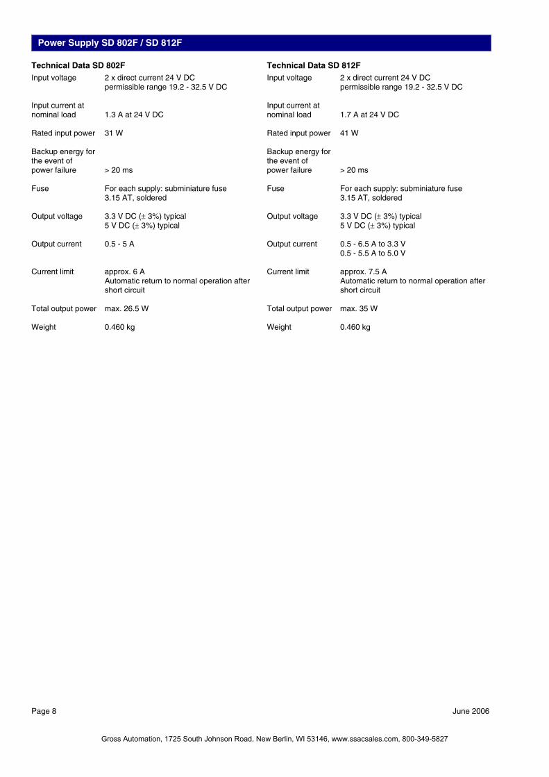
Power Supply SD 802F / SD 812F Technical Data SD 802F Input voltage 2 x direct current 24 V DC
permissible range 19.2 - 32.5 V DC Input current at nominal load 1.3 A at 24 V DC Rated input power 31 W Backup energy for the event of power failure > 20 ms Fuse For each supply: subminiature fuse
3.15 AT, soldered Output voltage 3.3 V DC (± 3%) typical
5 V DC (± 3%) typical Output current 0.5 - 5 A Current limit approx. 6 A
Automatic return to normal operation after short circuit
Total output power max. 26.5 W Weight 0.460 kg
Technical Data SD 812F Input voltage 2 x direct current 24 V DC
permissible range 19.2 - 32.5 V DC Input current at nominal load 1.7 A at 24 V DC Rated input power 41 W Backup energy for the event of power failure > 20 ms Fuse For each supply: subminiature fuse
3.15 AT, soldered Output voltage 3.3 V DC (± 3%) typical
5 V DC (± 3%) typical Output current 0.5 - 6.5 A to 3.3 V
0.5 - 5.5 A to 5.0 V Current limit approx. 7.5 A
Automatic return to normal operation after short circuit
Total output power max. 35 W Weight 0.460 kg
Gross Automation, 1725 South Johnson Road, New Berlin, WI 53146, www.ssacsales.com, 800-349-5827

Ethernet Modules EI 801F Features IEEE802.3 Ethernet standard Provides 10Base2 compliant communication 32-bit data bus Transmission rate 10 MBit/s Direct memory access to main memory, < 4% CPU over-
head for operation Optional battery for redundant battery backup of main
memory Description These communication modules provide Ethernet communica-tions to the system bus compliant with IEEE802.3 standard. Communications module, compliant with 10Base2 (Cheapernet) for thin coax cable installations. LED Displays State Off No supply voltage, module is isolated Green Power supply on, module identified and
ready to operate as configured. Orange Power supply on,
module identified and either: — normal transitory state after module
startup — configuration mode of Boot Loader Orange flashing Power supply on, module identified; mod-
ule not connected to proper bus structure. Red Power supply on and either: — module not yet identified (normal for
short time during module startup) — error occurred during module test Batt. Low Off Sufficient buffer battery voltage. Orange Buffer battery not found or low (insufficient
voltage). Front Panel Connections Coax connector
Technical Data Rated voltage 3.3 V / 5 V, ±3%, from CPU board
Power consumption max. 2.8 W
Thin Ethernet 10Base2
RAM and real-time-clock buffering time
PM 802F PM 803F New battery inserted ≥ 1,5 years without buffering After “Low” warning ≥ 10 days
Battery 3.6 V lithium battery, 950 mAh (not in the delivery)
Weight approx. 0.150 kg (without battery)
June 2006 Page 9
Gross Automation, 1725 South Johnson Road, New Berlin, WI 53146, www.ssacsales.com, 800-349-5827
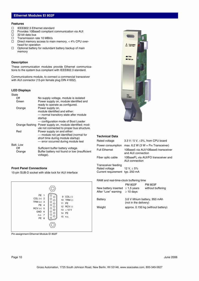
Ethernet Modules EI 802F Features IEEE802.3 Ethernet standard Provides 10Base5 compliant communication via AUI 32-bit data bus Transmission rate 10 MBit/s Direct memory access to main memory, < 4% CPU over-
head for operation Optional battery for redundant battery backup of main
memory Description These communication modules provide Ethernet communica-tions to the system bus compliant with IEEE802.3 standard. Communications module, to connect a commercial transceiver with AUI connector (15-pin female plug DIN 41652). LED Displays State Off No supply voltage, module is isolated Green Power supply on, module identified and
ready to operate as configured. Orange Power supply on,
module identified and either: — normal transitory state after module
startup — configuration mode of Boot Loader Orange flashing Power supply on, module identified; mod-
ule not connected to proper bus structure. Red Power supply on and either:
Page 10 June 2006
— module not yet identified (normal for short time during module startup)
— error occurred during module test Batt. Low Off Sufficient buffer battery voltage. Orange Buffer battery not found or low (insufficient
voltage). Front Panel Connections 15-pin SUB-D socket with slide lock for AUI interface
Technical Data Rated voltage 3.3 V / 5 V, ±3%, from CPU board
Power consumption max. 6.2 W (3 W + PIN Transceiver)
Full Ethernet 10Base5 via AUI/10Base5 transceiver and AUI connection
Fiber optic cable 10BaseFL via AUI/FO transceiver and AUI connection
Transceiver feeding Rated voltage 12 V, ± 5% Current requirement typ. 250 mA
RAM and real-time-clock buffering time
PM 802F PM 803F New battery inserted ≥ 1,5 years without buffering After “Low” warning ≥ 10 days
Battery 3.6 V lithium battery, 950 mAh (not in the delivery)
Weight approx. 0.150 kg (without battery)
PE 8
GND 6n.c. 7
COL (+) 2TRM (+) 3
RCV (+) 5
PE 1
PE 4
13 + 12 V 14 PE
15 n.c.
10 TRM (-) 11 PE
9 COL (-)
12 RCV (-)
Pin-assignment Ethernet Module EI 802F
Gross Automation, 1725 South Johnson Road, New Berlin, WI 53146, www.ssacsales.com, 800-349-5827
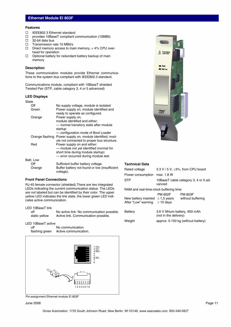
Ethernet Module EI 803F Features IEEE802.3 Ethernet standard provides 10BaseT compliant communication (10MBit) 32-bit data bus Transmission rate 10 MBit/s Direct memory access to main memory, < 4% CPU over-
head for operation Optional battery for redundant battery backup of main
memory Description These communication modules provide Ethernet communica-tions to the system bus compliant with IEEE802.3 standard. Communications module, compliant with 10BaseT shielded Twisted Pair (STP, cable category 3, 4 or 5 advanced) LED Displays State Off No supply voltage, module is isolated Green Power supply on, module identified and
ready to operate as configured. Orange Power supply on,
module identified and either: — normal transitory state after module
startup — configuration mode of Boot Loader Orange flashing Power supply on, module identified; mod-
ule not connected to proper bus structure. Red Power supply on and either: — module not yet identified (normal for
short time during module startup) — error occurred during module test Batt. Low Off Sufficient buffer battery voltage. Orange Buffer battery not found or low (insufficient
voltage). Front Panel Connections RJ-45 female connector (shielded).There are two integrated LEDs indicating the current communication status. The LEDs are not labeled but can be identified by their color. The upper yellow LED indicates the link state, the lower green LED indi-cates active communication. LED 10BaseT link off No active link. No communication possible. static yellow Active link. Communication possible. LED 10BaseT active off No communication.
Technical Data
Rated voltage 3.3 V / 5 V, ±3%, from CPU board
Power consumption max. 1.8 W
STP 10BaseT cable category 3, 4 or 5 ad-vanced
RAM and real-time-clock buffering time
PM 802F PM 803F New battery inserted ≥ 1,5 years without buffering After “Low” warning ≥ 10 days
Battery 3.6 V lithium battery, 950 mAh (not in the delivery)
Weight approx. 0.150 kg (without battery)
flashing green Active communication.
Pin-assignment Ethernet module EI 803F
June 2006 Page 11
Gross Automation, 1725 South Johnson Road, New Berlin, WI 53146, www.ssacsales.com, 800-349-5827
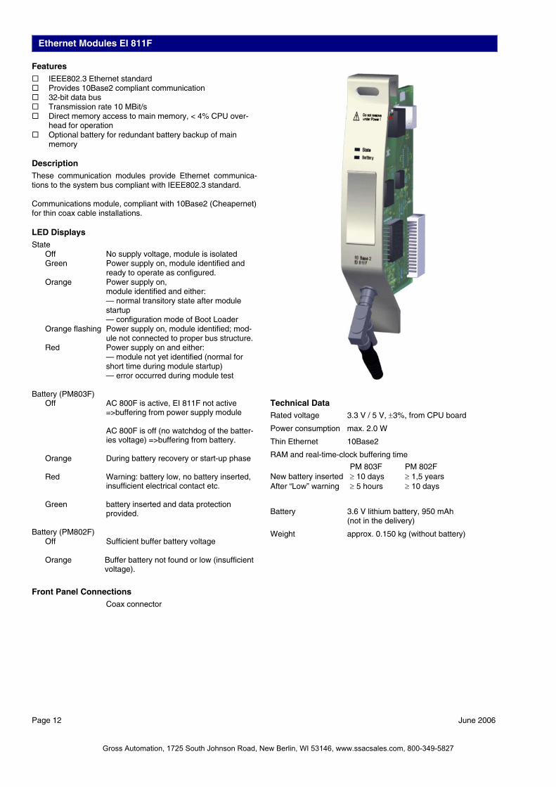
Ethernet Modules EI 811F Features IEEE802.3 Ethernet standard Provides 10Base2 compliant communication 32-bit data bus Transmission rate 10 MBit/s Direct memory access to main memory, < 4% CPU over-
head for operation Optional battery for redundant battery backup of main
memory Description These communication modules provide Ethernet communica-tions to the system bus compliant with IEEE802.3 standard. Communications module, compliant with 10Base2 (Cheapernet) for thin coax cable installations. LED Displays State Off No supply voltage, module is isolated Green Power supply on, module identified and
ready to operate as configured. Orange Power supply on,
module identified and either: — normal transitory state after module
startup — configuration mode of Boot Loader Orange flashing Power supply on, module identified; mod-
ule not connected to proper bus structure. Red Power supply on and either: — module not yet identified (normal for
short time during module startup) — error occurred during module test Battery (PM803F) Off AC 800F is active, EI 811F not active
=>buffering from power supply module
AC 800F is off (no watchdog of the batter-ies voltage) =>buffering from battery.
Orange During battery recovery or start-up phase Red Warning: battery low, no battery inserted,
insufficient electrical contact etc. Green battery inserted and data protection
provided. Battery (PM802F) Off Sufficient buffer battery voltage Orange Buffer battery not found or low (insufficient
Page 12 June 2006
voltage).
Front Panel Connections Coax connector
Technical Data Rated voltage 3.3 V / 5 V, ±3%, from CPU board
Power consumption max. 2.0 W
Thin Ethernet 10Base2
RAM and real-time-clock buffering time
PM 803F PM 802F New battery inserted ≥ 10 days ≥ 1,5 years After “Low” warning ≥ 5 hours ≥ 10 days
Battery 3.6 V lithium battery, 950 mAh (not in the delivery)
Weight approx. 0.150 kg (without battery)
Gross Automation, 1725 South Johnson Road, New Berlin, WI 53146, www.ssacsales.com, 800-349-5827

Ethernet Modules EI 812F Features IEEE802.3 Ethernet standard Provides 10Base5 compliant communication via AUI 32-bit data bus Transmission rate 10 MBit/s Direct memory access to main memory, < 4% CPU over-
head for operation Optional battery for redundant battery backup of main
memory Description These communication modules provide Ethernet communica-tions to the system bus compliant with IEEE802.3 standard. Communications module, to connect a commercial transceiver with AUI connector (15-pin female plug DIN 41652). LED Displays State Off No supply voltage, module is isolated Green Power supply on, module identified and
ready to operate as configured. Orange Power supply on,
module identified and either: — normal transitory state after module
startup — configuration mode of Boot Loader Orange flashing Power supply on, module identified; mod-
ule not connected to proper bus structure. Red Power supply on and either: — module not yet identified (normal for
short time during module startup) — error occurred during module test Battery (PM803F) Off AC 800F is active, EI 812F not active
=>buffering from power supply module
AC 800F is off (no watchdog of the batter-ies voltage) =>buffering from battery.
Orange During battery recovery or start-up phase Red Warning: battery low, no battery inserted,
insufficient electrical contact etc. Green battery inserted and data protection pro-
vided. Battery (PM802F) Off Sufficient buffer battery voltage Orange Buffer battery not found or low (insufficient
voltage).
Front Panel Connections 15-pin SUB-D socket with slide lock for AUI interface
Technical Data Rated voltage 3.3 V / 5 V, ±3%, from CPU board
Power consumption max. 4.9 W (2.3 W + PIN Transceiver)
Full Ethernet 10Base5 via AUI/10Base5 transceiver and AUI connection
Fiber optic cable 10BaseFL via AUI/FO transceiver and AUI connection
Transceiver feeding Rated voltage 12 V, ± 5% Current requirement typ. 250 mA RAM and real-time-clock buffering time
PM 803F PM 802F New battery inserted ≥ 10 days ≥ 1,5 years After “Low” warning ≥ 5 hours ≥ 10 days
Battery 3.6 V lithium battery, 950 mAh (not in the delivery)
Weight approx. 0.150 kg (without battery)
PE 8
PE 6n.c. 7
COL (+) 2TRM (+) 3
RCV (+) 5
PE 1
PE 4
13 + 12 V14 PE
15 n.c.
10 TRM (-)11 PE
9 COL (-)
12 RCV (-)
Pin-assignment Ethernet Module EI 812F June 2006 Page 13
Gross Automation, 1725 South Johnson Road, New Berlin, WI 53146, www.ssacsales.com, 800-349-5827
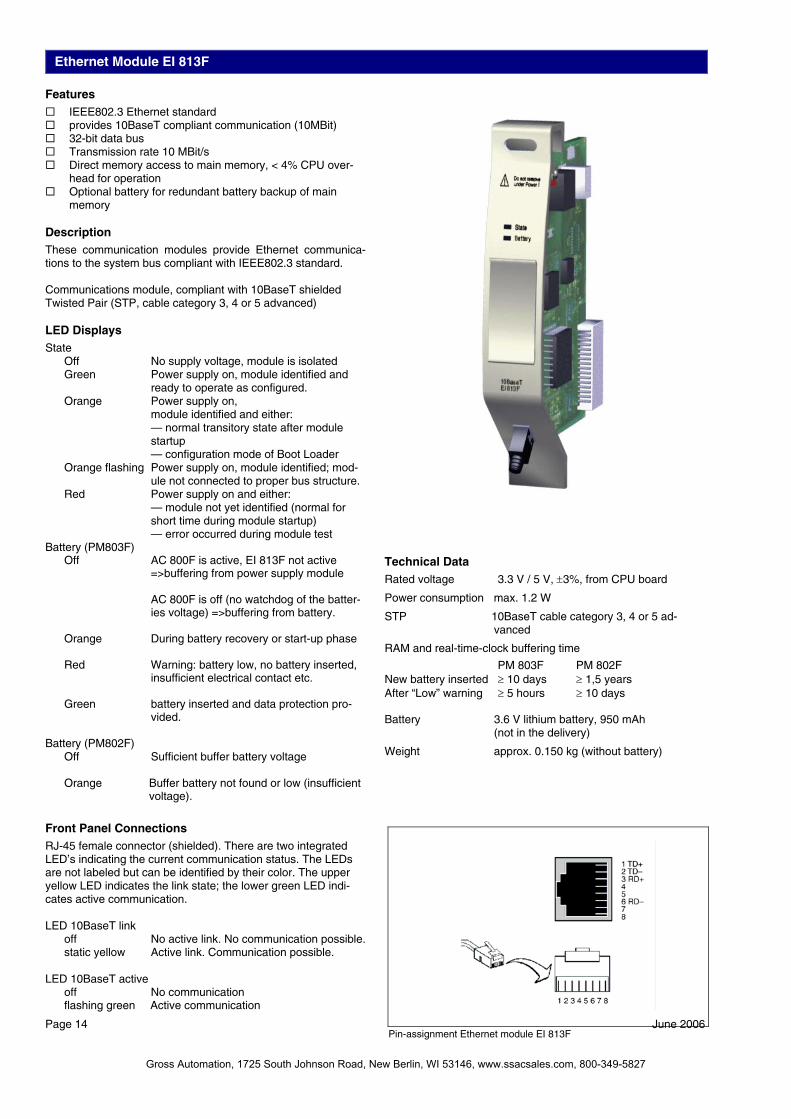
Ethernet Module EI 813F Features IEEE802.3 Ethernet standard provides 10BaseT compliant communication (10MBit) 32-bit data bus Transmission rate 10 MBit/s Direct memory access to main memory, < 4% CPU over-
head for operation Optional battery for redundant battery backup of main
memory Description These communication modules provide Ethernet communica-tions to the system bus compliant with IEEE802.3 standard. Communications module, compliant with 10BaseT shielded Twisted Pair (STP, cable category 3, 4 or 5 advanced) LED Displays State Off No supply voltage, module is isolated Green Power supply on, module identified and
ready to operate as configured. Orange Power supply on,
module identified and either: — normal transitory state after module
startup — configuration mode of Boot Loader Orange flashing Power supply on, module identified; mod-
ule not connected to proper bus structure. Red Power supply on and either: — module not yet identified (normal for
short time during module startup) — error occurred during module test Battery (PM803F) Off AC 800F is active, EI 813F not active
=>buffering from power supply module
AC 800F is off (no watchdog of the batter-ies voltage) =>buffering from battery.
Orange During battery recovery or start-up phase Red Warning: battery low, no battery inserted,
insufficient electrical contact etc. Green battery inserted and data protection pro-
vided. Battery (PM802F) Off Sufficient buffer battery voltage Orange Buffer battery not found or low (insufficient
voltage).
Page 14 June 2006
Front Panel Connections RJ-45 female connector (shielded). There are two integrated LED’s indicating the current communication status. The LEDs are not labeled but can be identified by their color. The upper yellow LED indicates the link state; the lower green LED indi-cates active communication. LED 10BaseT link off No active link. No communication possible. static yellow Active link. Communication possible. LED 10BaseT active off No communication
flashing green Active communication
Technical Data
Rated voltage 3.3 V / 5 V, ±3%, from CPU board
Power consumption max. 1.2 W
STP 10BaseT cable category 3, 4 or 5 ad-vanced
RAM and real-time-clock buffering time
PM 803F PM 802F New battery inserted ≥ 10 days ≥ 1,5 years After “Low” warning ≥ 5 hours ≥ 10 days Battery 3.6 V lithium battery, 950 mAh
(not in the delivery)
Weight approx. 0.150 kg (without battery)
Pin-assignment Ethernet module EI 813F
Gross Automation, 1725 South Johnson Road, New Berlin, WI 53146, www.ssacsales.com, 800-349-5827

CAN-3 Module FI 810F Features 3-channel CAN modules Transmission rate: up to1 MBd Module can be removed or inserted during operation Redundant operation, with redundant AC 800F
Description The FI 810F module provides connectivity to the Free-lance 2000 rack I/O. It provides functionality according CAN 2.0 specification and supports baud rates up 1 MBd. All interfaces are electrically isolated and support redundant operation in con-junction with a second AC 800F. Only one FI 810F module may be connected per AC 800F. The slot of the FI 810F module is preset to F1. LED Displays State Off No supply power, module is isolated Green Module is active and working properly Orange Module has been identified by AC 800F,
but has not yet been activated Red Module powered up, but not yet identified,
or an error has occurred RxD0 Green Receive data on channel 0 TxD0 Green Transmit data on channel 0 RxD1 Green Receive data on channel 1 TxD1 Green Transmit data on channel 1 RxD2 Green Receive data on channel 2 TxD2 Green Transmit data on channel 2 Front Panel Connections CAN 3 9-pin female connector
Technical Data
Rated voltage 5 V, ± 3% from basic unit Power consumption 1.6 W - 2.6 W,
appending from communication Channel supply: Raged voltage 5 V, ± 10% Power consump. 0.15 W, when idling per channel 0.30 W, during communication Weight approx. 0.145 kg
CAN 0 H 2CAN 0 L 3
n.c. 5
n.c. 1
CAN 2 L 4
7 CAN 1 L8 CAN 2 H
6 CAN 1 H
9 n.c.
Pin-assignment CAN connector on FI 810F
June 2006 Page 15
Gross Automation, 1725 South Johnson Road, New Berlin, WI 53146, www.ssacsales.com, 800-349-5827

Serial Module FI 820F Features Provides 2 serial interfaces Transmission rates up to 38.4 KBaud configurable Physical interfaces RS485, RS422, RS232 selectable Electrical isolation Module can be removed or inserted during operation Redundant operation, with redundant AC 800F
Description The FI 820F module provides connectivity to a variety of serial fieldbuses and serial protocols. Standard protocol is MODBUS By using different connection cables the physical interface can easily be selected: RS485 (half duplex), RS422 (full duplex) or RS232. All interfaces are electrically isolated and support re-dundant operation in conjunction with a second AC 800F. LED Displays State Off No supply power, module is isolated Green Module is active and working properly Orange Module has been identified by AC 800F,
but has not yet been activated Red Module powered up, but not yet identified,
or an error has occurred RxD0 Green Receive data on channel 0 TxD0 Green Transmit data on channel 0 RxD1 Green Receive data on channel 1 TxD1 Green Transmit data on channel 1
Page 16 June 2006
Front Panel Connections Serial 26-pin female connector
Technical Data
Rated voltage 5 V, ± 3% from basic unit Power consumption 1.6 - 2.6 W,
appending from communication Channel supply: Raged voltage 5 V, ± 10% Power consump. 0.15 W, when idling per channel 0.30 W, during communication Output voltage for termination (Vcc_Term) Rated voltage 5 V, ± 10% Max. output current 20 mA Weight approx. 0.145 kg
20 GND Ch0
21 n.c.
19 VCC_Term Ch0
22 n.c.
CTS (RS232) Ch1 8
RxD (RS232) Ch1 6
TxD (RS232) Ch1 7
TxD (RS232) Ch0 2
CTS (RS232) Ch0 3
n.c. 5
RxD (RS232) Ch0 1
RTS (RS232) Ch0 4
RTS (RS232) Ch1 9
24 n.c.
25 VCC_Term Ch1
23 n.c.
26 GND Ch117 Tx+ (RS422) Ch1
15 RxTx+ (RS485)/ Rx+ (RS422) Ch1
16 RxTx– (RS485)/ Rx– (RS422) Ch1
11 RxTx– (RS485)/ Rx– (RS422) Ch0
12 Tx+ (RS422) Ch0
14 n.c.
10 RxTx+ (RS485)/ Rx+ (RS422) Ch0
13 Tx– (RS422) Ch0
18 Tx– (RS422) Ch1
Pin assignment serial connector on FI 820F
Gross Automation, 1725 South Johnson Road, New Berlin, WI 53146, www.ssacsales.com, 800-349-5827

Profibus Module FI 830F Features PROFIBUS-DP Module (DIN 19245) Transmission rate up 12 MBd supports up to 126 slaves Physical interface: RS485 Electrical isolation Shared memory (256 KB) onboard, to minimize the use of
basic unit memory. Module can be removed or inserted during operation Redundant operation, with redundant AC 800F
Description The FI 830F module interfaces to the Profibus fieldbus. It pro-vides functionality according to the PROFIBUS-DP V1 standard (DIN 19245 amendment 1) and supports baud rates up 12 MBd. The module is the master on the Profibus line and allows con-necting up to 126 Profibus slaves. Configuration and parame-terization is carried out completely with Control Builder F — no additional external configuration tools are required. Line redundancy can be achieved using an external device (RLM 01) which drives two Profibus lines in parallel. In conjunc-tion with a second AC 800F the module can also operate in a redundant-master mode without limiting any other feature. LED Displays State Off No supply power, module is isolated Green Module is active and working properly Orange Module has been identified by AC 800F,
but has not yet been activated Red Module powered up, but not yet identified,
or an error has occurred Busy Off Module is in passive state on the Profibus. Green Module has token and, thus, is acting as
the master Front Panel Connections Profibus 9-pin female connector (DIN 41652)
Technical Data
Power consumption In the active state, depends on the com-munication cycle time: 2.8 W
Max. output current 20 mA for bus termination/repeater supply
Output voltage 5 V, ± 5% Overvoltage protection +7.5 V / -5 V
either transmission line to GND.
Weight approx. 0.150 kg
n.c. 2RxD+/TxD+ 3
GND 5
Shield 1
RTS 4
7 n.c.8 RxD-/TxD-
6 VP (5 V / 20 mA)
9 n.c.
Pin-assignment Profibus connector on FI 830F
June 2006 Page 17
Gross Automation, 1725 South Johnson Road, New Berlin, WI 53146, www.ssacsales.com, 800-349-5827

FF/HSE Module FI 840F Features ARM-CPU with integrated Ethernet controller, 32-bit data
bus, 32-bit address bus Flash EPROM for module CPU and protocol software. Software/firmware update without EPROM exchange. Separate memory for module CPU. Shared memory for data exchange between main proces-
sor and module CPU. Data protection by parity check. Automatic detection if 10BaseT or 100BaseTX is con-
nected. Electrical isolation for TP interface ESD protector on RJ45 socket Serial interface/Manchester encoder for generating a serial
bit stream EEPROM for configuration data and diagnostic data mem-
ory independent from battery buffering. Isolator for electrical isolation of the bus signals RJ45 connector with two link LEDs.
Description The FI 840F is a high speed ethernet fieldbus module designed for fast data exchange in production engineering with decentral-ized peripherals. The FF/HSE module FI 840F is a Fieldbus-Foundation®-(FF)-Master. Using the Control Builder F it is possible to configure diverse Fieldbus Foundation®-devices. The FF/HSE module FI 840F is designed to connect the AC 800F to a FF/HSE network. It can be mounted on slots F1 ... F4. It is used if high transmission rates are required or shall be made available for future use. FF/HSE wiring is always a point-to-point connection. Therefor a networks with more than two nodes always requires network switches or hubs.
RJ-45 female connector (shielded). There are two integrated LEDs indicating the current communication status. The LEDs are not labeled but can be identified by their color. The upper yellow LED indicates the transmission rate, the lower green LED indicates the communication state.
LED Displays State off No voltage applied, module is separated. green Power on, module is identified and ready
for operation according to the configura-tion
orange Power on, module has been identified by AC 800F,
- intermediate state during start-up
Page 18 June 2006
- configuration mode of the boot loader flashing orange Power on, module has been identified by
AC 800F. Module is not connected to corrected bus physics
red Power on - Module not yet identified (on a short-
term basis during start up) - an error has occurred during module
test
Front Panel Connections
LED FF/HSE Speed off Module has detected 10 MBit/s data con-
nection. static yellow Module has detected 100 MBit/s data con-
nection.
LED FF/HSE Link off No active link, neither 10Mbit nor 100 MBit. No communica-
tion possible. static green Active link. Communication possible. No
data transfer. flashing green Active link. Communication possible.
Pin-assignment FF/HSE module FI 840F
Gross Automation, 1725 South Johnson Road, New Berlin, WI 53146, www.ssacsales.com, 800-349-5827

FF/HSE Module FI 840F Technical Data
Rated voltage 5 V ± 3%, 3.3 V ± 3 % and 2.5 V ± 5 %
Power consumption in active state 1.4 W - 2.1 W depending on communica-
tions load
Module memory 8 MBytes synchronous dynamic RAM
Shared memory 1 MByte synchronous static RAM used for data exchange between CPU board and module.
Firmware memory 2 MByte Flash EPROM, 32-bit word length, capable of programming in the sys-tem and direct programming from AC 800F CPU board
EEPROM Serial 16 kBit EEPROM, write cycles ≥ 107, buffering time ≥ 10 years
Weight approx. 0.150 kg
Static characteristics Power consumption max. 2.1 W
Medium 100BaseTx cable, category 5
Max. segment length 100 m
Max. number of nodes per segment 2
Dynamic characteristics Transmission rate 10 Mbit/s or 100 Mbit/s
June 2006 Page 19
Gross Automation, 1725 South Johnson Road, New Berlin, WI 53146, www.ssacsales.com, 800-349-5827

Battery Module AM 801F Features Provides battery backup for PM802F only Enables redundant battery energy backup on the AC 800F
Description The battery module provides for retention of the AC 800F RAM data when the AC 800F is off or has no Ethernet module. The battery module is used when the AC 800F is used as a stand-alone device, i.e. when it has no Ethernet connection, or when the only existing Ethernet module is to be replaced with-out the AC 800F loosing its configuration data. LED Displays State Off No supply power, module is isolated Green Power supply on, module identified and
ready to operate as configured. Orange Power supply on, module identified and
either: — normal transitory state after module
startup — configuration mode of Boot Loader Red Module power supply is on and either:
— module not yet identified (normal for short time, during module startup)
— error occurred during module test Batt Low Off Sufficient buffer battery voltage. Orange Buffer battery not found or low (insuffi-
cient voltage). Technical Data
Rated voltage 3.3 V / 5 V, ±3%, from CPU board Power consumption approx. 0.25 W
Page 20 June 2006
Battery 3.6 V lithium battery, 950 mAh
(included in delivery) Low battery signaling ≤ 2.4 V
RAM and real-time-clock buffering time New battery inserted ≥ 1,5 years After “Low” warning ≥ 10 days
Weight approx. 0.150 kg without buffer battery approx. 0.170 kg with buffer battery
Gross Automation, 1725 South Johnson Road, New Berlin, WI 53146, www.ssacsales.com, 800-349-5827
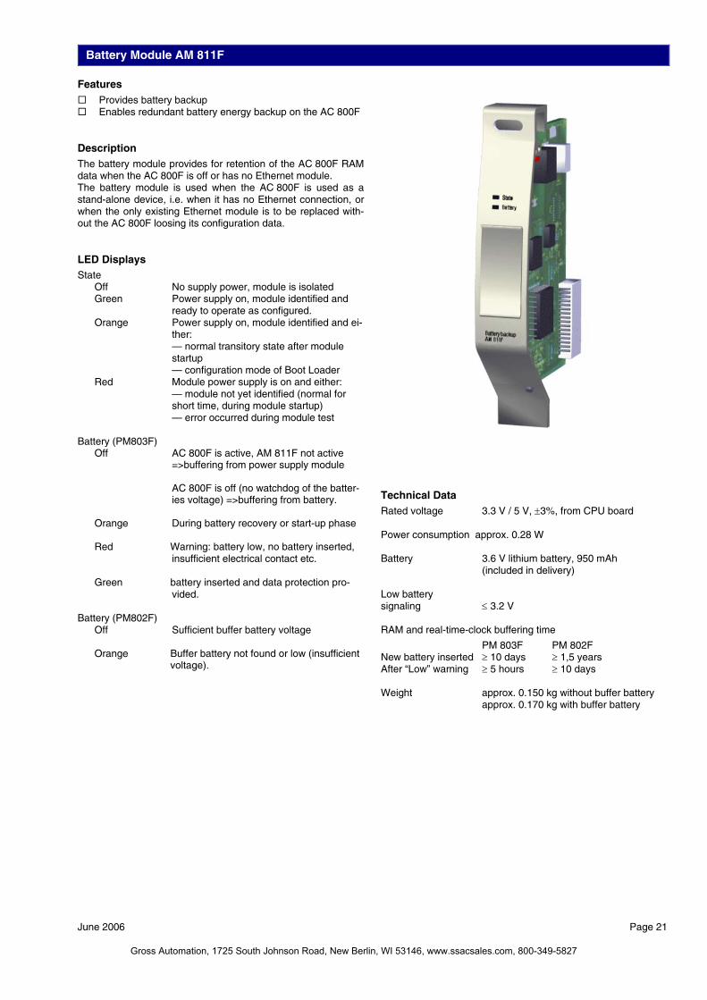
Battery Module AM 811F Features Provides battery backup Enables redundant battery energy backup on the AC 800F
Description The battery module provides for retention of the AC 800F RAM data when the AC 800F is off or has no Ethernet module. The battery module is used when the AC 800F is used as a stand-alone device, i.e. when it has no Ethernet connection, or when the only existing Ethernet module is to be replaced with-out the AC 800F loosing its configuration data. LED Displays State Off No supply power, module is isolated Green Power supply on, module identified and
ready to operate as configured. Orange Power supply on, module identified and ei-
ther: — normal transitory state after module
startup — configuration mode of Boot Loader Red Module power supply is on and either: — module not yet identified (normal for
short time, during module startup) — error occurred during module test Battery (PM803F) Off AC 800F is active, AM 811F not active
=>buffering from power supply module
AC 800F is off (no watchdog of the batter-ies voltage) =>buffering from battery.
Orange During battery recovery or start-up phase Red Warning: battery low, no battery inserted,
insufficient electrical contact etc. Green battery inserted and data protection pro-
vided. Battery (PM802F) Off Sufficient buffer battery voltage Orange Buffer battery not found or low (insufficient
voltage).
Technical Data
Rated voltage 3.3 V / 5 V, ±3%, from CPU board Power consumption approx. 0.28 W Battery 3.6 V lithium battery, 950 mAh
(included in delivery) Low battery signaling ≤ 3.2 V RAM and real-time-clock buffering time
PM 803F PM 802F New battery inserted ≥ 10 days ≥ 1,5 years After “Low” warning ≥ 5 hours ≥ 10 days Weight approx. 0.150 kg without buffer battery
approx. 0.170 kg with buffer battery
June 2006 Page 21
Gross Automation, 1725 South Johnson Road, New Berlin, WI 53146, www.ssacsales.com, 800-349-5827
Page 22 June 2006
Environmental Conditions Permissible ambient temperature 0 °C - 60 °C
Permissible module internal tem-perature
0 °C - 70 °C (temperature monitoring on basic unit)
Temperature gradient In operation: 1 °C/min, according to DIN IEC 68, Part 14/EN 60068-2-14(11.99)
Transport and storage tempera-ture
-25 °C - +85 °C
Permissible relative humidity Non-condensing, ≤ 80 % annual average ≤ 95 % for 30 days per year maximum
Degree of humidity RH-1, according to EN 61131-2: 1994 (IEC 1131-2)
Climatic category KWF according to DIN 40040 (replaced by EN 60721-3-3 and EN 61709) 3K3 according to DIN IEC 721/EN 60721-3-3
Degree of protection For basic unit with module complement: IP20
Electromagnetic Compatibility (EMC) Complies with the protection requirements of EMI directive 89/336/EEC of May 1989 and EMVG of Nov. 1992.
Interference suppression According to EN 55022 / 4.1988 DIN VDE 0878 Part 22 / 11.89, class B
Noise immunity Basic standard: EN 50082, VDE 0839 - Part 82-2, EN 61000-6-2
Tested according to EN61000-4; VDE 0847
• Parts 1 to 6,8,11, Degree 3, are met with shielded communication cables
• The industrial standard to NAMUR 21 / 8.98 is met
Electrical Protection Safety class II
Overvoltage category II for all connectors, pollution degree 2
Designed according to IEC 1010-1 (1990 - 09); EN 61010-1 / 3.94 or DIN/EN 61010 - Part 1 / 3.94 (VDE 0411 - Part 1), CSAC 22.2, No. 1010-1 and No. 213 (Class I, Div 2), SIQ (CB Scheme 97NK2421), CSA/NTRL.
Module supply power Extra low voltage with protective separation from other circuits which may be grounded according to DIN VDE 0100, Part 410-1.97/IEC 60364-4-41/10.92
Power supply SA 801F, SA 811F Safety isolating transformer according to DIN VDE 0551, Part 1 (9.95); EN 60742
Optocoupler for protective separation against electrical shock (German standard VDE 0884 / 8.87)
Power supply SD 802F, SD 812F No elec. separation!
Shock and Vibration Data Tested according to DIN IEC 68, Part 2-6, 2-27/EN 60068-2-6, 2-27 (11.99)
Transport
Shock 30 g/11 ms/ 3 times to each axis Max. values for the individual modules. The values are valid for correct mounted modules.
In operation
Vibration, 3x5 cycles 2 g/0.15 mm/5 - 150 Hz
Gross Automation, 1725 South Johnson Road, New Berlin, WI 53146, www.ssacsales.com, 800-349-5827

Power Dissipation for the Calculation of Cooling System The following table lists the anticipated power dissipation (heat dissipation) of individual AC 800F modules. The data for the modules contain the combined power con-sumption from internal and external supply sources. For de-tailed information see the Mounting and Installation Instruc-tions, AC 800F manual.
Module Max. Power Dissipation
Basic unit PM 802F
with power supply SA 801Fwith power supply SD 802F
20.8 W 10.8 W
Basic unit PM 803F
with power supply SA 811Fwith power supply SD 812F
26.8 W 13.8 W
Ethernet module EI 801F EI 811F
2.8 W 2.0 W
Ethernet module EI 802F
Without transceiver supplyWith transceiver supply
3.0 W 6.2 W
Ethernet module EI 812F
Without transceiver supplyWith transceiver supply
2.3 W 4.9 W
Ethernet module EI 803F EI 813F
1.8 W 1.2 W
CAN-module FI 810F 2.6 W
Serial module FI 820F 2.6 W
PROFIBUS module FI 830F 2.8 W
FF/HSE module FI 840F 2.1 W
Battery module AM 801FAM 811F
0.25 W 0.28 W
June 2006 Page 23
Gross Automation, 1725 South Johnson Road, New Berlin, WI 53146, www.ssacsales.com, 800-349-5827

Gross Automation, 1725 South Johnson Road, New Berlin, WI 53146, www.ssacsales.com, 800-349-5827