SCADA and MODBUS Commands and Telemetry Features€¦ · Contact Raveon sales to have the device...
37
SCADA and MODBUS Commands and Telemetry Features By John Sonnenberg Raveon Technologies Corp Overview Raveon’s M8, M6, and Tech Series of radio modems have many SCADA and Telemetry features such as: A. IO pins. A number of IO pins can be used as digital inputs or digital outputs. B. GPIO interface on the Tech Series enclosures have digital IO, open source switches, Switched DC voltage and other features. C. Internal sensors in the modem are registers that contain additional telemetry data such as a. Switch counters (count digital input pulses and changes) b. State timers (track on and off time) c. Accelerometers (Angle and motion sensors) d. GPS location. (Lat, Lon, Speed, Heading, Altitude, satellite count, UTC time) e. Temperature. (The temperature of the modem) f. Voltages (The input voltage to the modem) The SCADA and Telemetry features in the M8, M6, and Tech Series radio modems can be controlled using a number of mechanisms: A. Local commands. Issue commands using a serial port to read and manage Telemetry parameters. Use WMX feature or RPR command to remotely manage a telemetry feature. B. Over the Air commands. Commands to set or read I/O Telemetry parameters can be sent over the air using WMX built commands or manually in the command mode with the RPR command from a remote radio modem. C. Modbus. Digital I/Os may be managed using MODBUS type commands. This document describes how to do this. MODBUS is a registered trademark of MODICON, Inc. This industry standard protocol has many user applications from many companies to control devices that process Modbus messages like Raveon’s radio modems do. D. MIMIC. Two radio modems can be setup to MIMIC each-others IO pins. In the MIMIC mode, the state of one device’s input pin is automatically transferred to the other device’s output pin. It does that at configurable intervals, and with default settings. MIMIC communications is great for sending switch status to remote devices. Technical Brief AN230 Rev A1
Transcript of SCADA and MODBUS Commands and Telemetry Features€¦ · Contact Raveon sales to have the device...
SCADA and MODBUS Commands and Telemetry Features
By John Sonnenberg Raveon Technologies Corp
Overview
Raveon’s M8, M6, and Tech Series of radio modems have many SCADA and Telemetry features such as:
A. IO pins. A number of IO pins can be used as digital inputs or digital outputs.
B. GPIO interface on the Tech Series enclosures have digital IO, open source switches, Switched DC voltage and other features.
C. Internal sensors in the modem are registers that contain additional telemetry data such as
a. Switch counters (count digital input pulses and changes) b. State timers (track on and off time) c. Accelerometers (Angle and motion sensors) d. GPS location. (Lat, Lon, Speed, Heading, Altitude, satellite count, UTC time) e. Temperature. (The temperature of the modem) f. Voltages (The input voltage to the modem)
The SCADA and Telemetry features in the M8, M6, and Tech Series radio modems can be controlled using a number of mechanisms:
A. Local commands. Issue commands using a serial port to read and manage Telemetry parameters. Use WMX feature or RPR command to remotely manage a telemetry feature.
B. Over the Air commands. Commands to set or read I/O Telemetry parameters can be sent over the air using WMX built commands or manually in the command mode with the RPR command from a remote radio modem.
C. Modbus. Digital I/Os may be managed using MODBUS type commands. This document describes how to do this. MODBUS is a registered trademark of MODICON, Inc. This industry standard protocol has many user applications from many companies to control devices that process Modbus messages like Raveon’s radio modems do.
D. MIMIC. Two radio modems can be setup to MIMIC each-others IO pins. In the MIMIC mode, the state of one device’s input pin is automatically transferred to the other device’s output pin. It does that at configurable intervals, and with default settings. MIMIC communications is great for sending switch status to remote devices.
Technical Brief AN230 Rev A1
E. Auto Report. IO status and registers can be automatically reported at configurable report rates and preset thresholds.
These SCADA features within Raveon’s wireless modems have many features and advantages:
A. Security. Over-the-air data communication can be encrypted with AES. Each radio modem can have encryption enabled, so no 3rd party can access the wireless system.
B. Radio IDs. All Raveon data radio modems have a 16 bit ID code in them and address mask. IDs can be used to ensure which radio talks to which radio, or to setup radios in groups. A listen address is also included in each radio so broadcasts to specific groups is easy.
C. Repeater. All Raveon data radio modems have a store-forward option, that can be configured by ID and groups of IDs so a radio modem can be used to store and forward messages.
D. GPS location. All Raveon data radio modems have a GPS option for location and can be configured to periodically report their location and status.
E. TDMA. All Raveon data radio modems have a GPS option for location and TDMA timing. If fast updates are needed, TDMA slot timing is very efficient and ensure no RF interference.
F. Watchdog. All Raveon product incorporate a hardware watchdog timer, to fully reset the product in case some electrical or firmware problem exists. The makes remote systems very reliable.
GPIO [ G ] General Purpose IO
The Tech Series GPIO version of the RV-M21 and RV-M22 series radio modems is ideal for SCADA and telemetry. Here is a summary of the standard IO features. If you need other IO features or additional IO, please contact Raveon sales personnel.
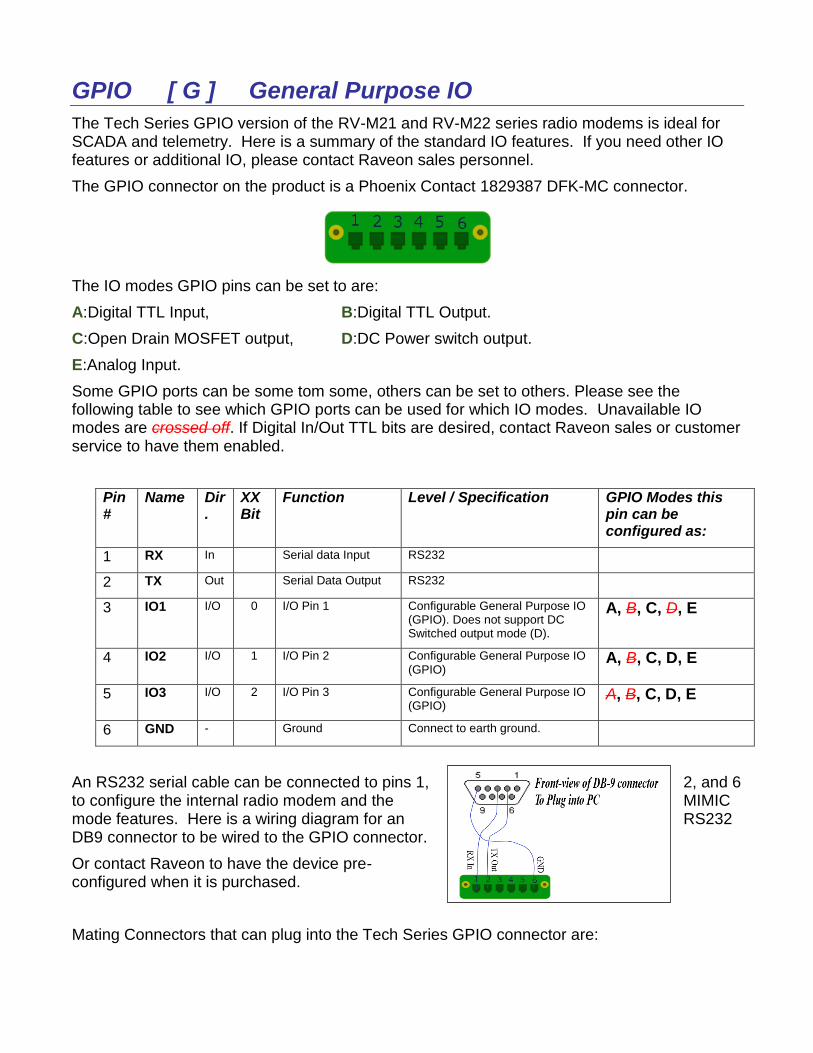
The GPIO connector on the product is a Phoenix Contact 1829387 DFK-MC connector.
The IO modes GPIO pins can be set to are:
A:Digital TTL Input, B:Digital TTL Output.
C:Open Drain MOSFET output, D:DC Power switch output.
E:Analog Input.
Some GPIO ports can be some tom some, others can be set to others. Please see the following table to see which GPIO ports can be used for which IO modes. Unavailable IO modes are crossed off. If Digital In/Out TTL bits are desired, contact Raveon sales or customer service to have them enabled.
Pin #
Name Dir.
XX Bit
Function Level / Specification GPIO Modes this pin can be configured as:
1 RX In Serial data Input RS232
2 TX Out Serial Data Output RS232
3 IO1 I/O 0 I/O Pin 1 Configurable General Purpose IO (GPIO). Does not support DC Switched output mode (D).
A, B, C, D, E
4 IO2 I/O 1 I/O Pin 2 Configurable General Purpose IO (GPIO)
A, B, C, D, E
5 IO3 I/O 2 I/O Pin 3 Configurable General Purpose IO (GPIO)
A, B, C, D, E
6 GND - Ground Connect to earth ground.
An RS232 serial cable can be connected to pins 1, 2, and 6 to configure the internal radio modem and the MIMIC mode features. Here is a wiring diagram for an RS232 DB9 connector to be wired to the GPIO connector.
Or contact Raveon to have the device pre-configured when it is purchased.
Mating Connectors that can plug into the Tech Series GPIO connector are:
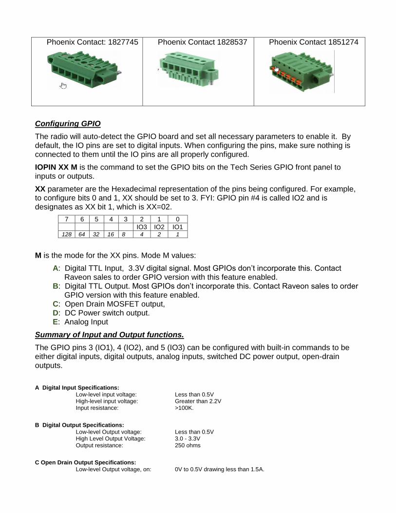
Phoenix Contact: 1827745
Phoenix Contact 1828537
Phoenix Contact 1851274
Configuring GPIO
The radio will auto-detect the GPIO board and set all necessary parameters to enable it. By default, the IO pins are set to digital inputs. When configuring the pins, make sure nothing is connected to them until the IO pins are all properly configured.
IOPIN XX M is the command to set the GPIO bits on the Tech Series GPIO front panel to inputs or outputs.
XX parameter are the Hexadecimal representation of the pins being configured. For example, to configure bits 0 and 1, XX should be set to 3. FYI: GPIO pin #4 is called IO2 and is designates as XX bit 1, which is XX=02.
7 6 5 4 3 2 1 0
IO3 IO2 IO1 128 64 32 16 8 4 2 1
M is the mode for the XX pins. Mode M values:
A: Digital TTL Input, 3.3V digital signal. Most GPIOs don’t incorporate this. Contact Raveon sales to order GPIO version with this feature enabled.
B: Digital TTL Output. Most GPIOs don’t incorporate this. Contact Raveon sales to order GPIO version with this feature enabled.
C: Open Drain MOSFET output, D: DC Power switch output. E: Analog Input
Summary of Input and Output functions.
The GPIO pins 3 (IO1), 4 (IO2), and 5 (IO3) can be configured with built-in commands to be either digital inputs, digital outputs, analog inputs, switched DC power output, open-drain outputs.
A Digital Input Specifications:
Low-level input voltage: Less than 0.5V High-level input voltage: Greater than 2.2V Input resistance: >100K.
B Digital Output Specifications:
Low-level Output voltage: Less than 0.5V High Level Output Voltage: 3.0 - 3.3V Output resistance: 250 ohms
C Open Drain Output Specifications:
Low-level Output voltage, on: 0V to 0.5V drawing less than 1.5A.
Open drain off leakage resistance 500uA, 0-5V, < 3mA 5-10V. High Level Output Voltage, off: 0 - 20V Output resistance, on: <250 milliohms to ground Controlling 0=OFF(Open Circuit). 1=ON (Open drain to ground on) D Switched DC power output: (IO2 and IO3) IO1 does not have this capability.
Output voltage, on: Same as DC input, 90%-100%. Maximum Output Current 2.0 amps On state internal resistance 100-250mOhms. Maximum reverse input voltage when off DC input + 150mV Off output off leakage resistance 5-200uA Maximum voltage into IO pin: Less than or equal to DC input voltage. .
FYI, the DC power connector on the RV-M21 and RV-M22 Tech Series radio modems is a Binder 09 3419 81 03.
SCADA Codes
Over time, Raveon will have a variety of SCADA products. Every SCADA product has a “SCADA Code” within them that can be read with the Modbus commands described in this document.
The RV-M21 Tech Series radio with the GPIO three IO pins on it is SCADA Code 3. Use Modbus command 03 (read Holding Register) to read this code from the product.
FIO [ D ] Flexible IO
The Tech Series FIO Flexible IO version of the RV-M21 and RV-M22 series radio modems is ideal for SCADA and telemetry. Here is a summary of the standard FIO features. If you need other IO features or additional IO, please contact Raveon sales personnel.
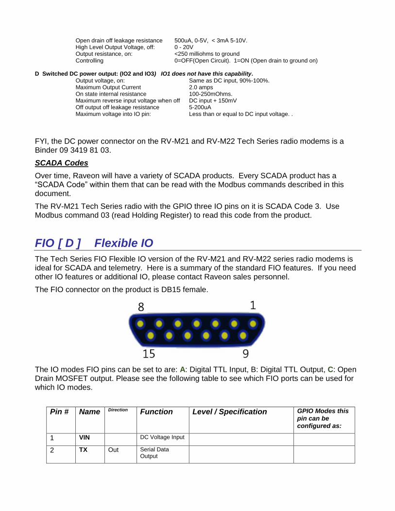
The FIO connector on the product is DB15 female.
The IO modes FIO pins can be set to are: A: Digital TTL Input, B: Digital TTL Output, C: Open Drain MOSFET output. Please see the following table to see which FIO ports can be used for which IO modes.
Pin # Name Direction Function Level / Specification GPIO Modes this pin can be configured as:
1 VIN DC Voltage Input
2 TX Out Serial Data Output
3 OD0 Out Open Drain Out C
4 IO0 I/O I/O Pin 2 Detail IO pin. Input or output. A, B
12 IO1 I/O I/O Pin 2 Detail IO pin. Input or output. A, B
5 IO2 I/O I/O Pin 2 Detail IO pin. Input or output. A, B
13 IO3 I/O I/O Pin 2 Detail IO pin. Input or output. A, B
6 IO4 I/O I/O Pin 2 Detail IO pin. Input or output. A, B
14 IO5 I/O I/O Pin 2 Detail IO pin. Input or output. A, B
7 IO6 I/O I/O Pin 2 Detail IO pin. Input or output. A, B
15 IO7 I/O I/O Pin 2 Detail IO pin. Input or output. A, B
9 RX In Serial data Input RS232
10 VDIG Digital Voltage The internal IO port voltage regulator outputs its voltage on this pin.
A, B, C, D, E
8, 11 GND - Ground
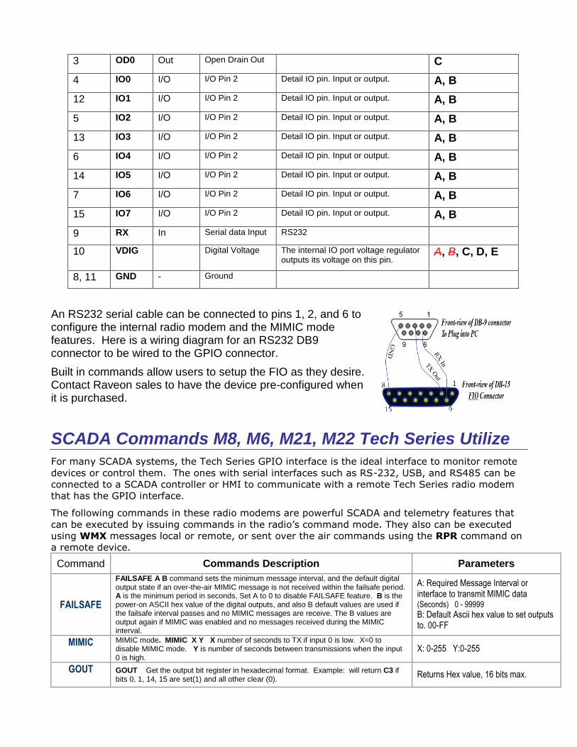
An RS232 serial cable can be connected to pins 1, 2, and 6 to configure the internal radio modem and the MIMIC mode features. Here is a wiring diagram for an RS232 DB9 connector to be wired to the GPIO connector.
Built in commands allow users to setup the FIO as they desire. Contact Raveon sales to have the device pre-configured when it is purchased.
SCADA Commands M8, M6, M21, M22 Tech Series Utilize
For many SCADA systems, the Tech Series GPIO interface is the ideal interface to monitor remote
devices or control them. The ones with serial interfaces such as RS-232, USB, and RS485 can be
connected to a SCADA controller or HMI to communicate with a remote Tech Series radio modem
that has the GPIO interface.
The following commands in these radio modems are powerful SCADA and telemetry features that
can be executed by issuing commands in the radio’s command mode. They also can be executed
using WMX messages local or remote, or sent over the air commands using the RPR command on
a remote device.
Command Commands Description Parameters
FAILSAFE
FAILSAFE A B command sets the minimum message interval, and the default digital output state if an over-the-air MIMIC message is not received within the failsafe period. A is the minimum period in seconds, Set A to 0 to disable FAILSAFE feature. B is the power-on ASCII hex value of the digital outputs, and also B default values are used if the failsafe interval passes and no MIMIC messages are receive. The B values are output again if MIMIC was enabled and no messages received during the MIMIC interval.
A: Required Message Interval or interface to transmit MIMIC data (Seconds) 0 - 99999 B: Default Ascii hex value to set outputs to. 00-FF
MIMIC
MIMIC mode. MIMIC X Y X number of seconds to TX if input 0 is low. X=0 to disable MIMIC mode. Y is number of seconds between transmissions when the input 0 is high.
X: 0-255 Y:0-255
GOUT
GOUT Get the output bit register in hexadecimal format. Example: will return C3 if bits 0, 1, 14, 15 are set(1) and all other clear (0).
Returns Hex value, 16 bits max.
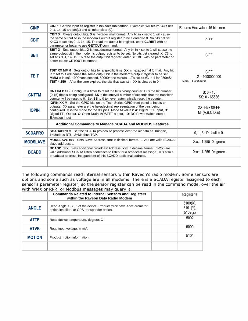
GINP GINP Get the input bit register in hexadecimal format. Example: will return C3 if bits 0, 1, 14, 15 are set(1) and all other clear (0).
Returns Hex value, 16 bits max.
CBIT
CBIT X Clears output bits, X is hexadecimal format. Any bit in x set to 1 will cause the same output bit in the modem’s output register to be cleared to 0. No bits get set. X=C3 to set bits 0, 1, 14, 15. To read the output bit register, enter CLRBIT with no parameter or better to use GETOUT command.
0-FF
SBIT
SBIT X Sets output bits, X is hexadecimal format. Any bit in x set to 1 will cause the same output bit in the modem’s output register to be set. No bits get cleared. X=C3 to set bits 0, 1, 14, 15. To read the output bit register, enter SETBIT with no parameter or better to use GETOUT command.
0-FF
TBIT
TBIT XX MMM Sets output bits for a specific time, XX is hexadecimal format. Any bit in x set to 1 will cause the same output bit in the modem’s output register to be set. MMM is in mS. 1000=one second, 60000=one minute,…To set bit #3 to 1 for 250mS: TBIT 4 250 After the time expires, the bits that was st in XX is cleared to 0.
0-FF 2 – 4000000000
(2mS – 1100hours)
CNTTM CNTTM B SS Configure a timer to reset the bit’s binary counter. B is the bit number (0-15) that is being configured. SS is the interval number of seconds that the transition counter will be reset to 0. Set SS to 0 to never automatically reset the counter.
B: 0 - 15 SS: 0 - 65536
IOPIN
IOPIN XX M Set the GPIO bits on the Tech Series GPIO front panel to inputs or outputs. XX parameter are the hexadecimal representation of the pins being configured. M is the mode for the XX pins. Mode M values: A: Digital TTL Input, B: Digital TTL Output. C: Open Drain MOSFET output, D: DC Power switch output. E:Analog Input
XX=Hex 00-FF
M=(A,B,C,D,E)
Additional Commands to Manage SCADA and MODBUS Features
SCDAPRO SCADAPRO x Set the SCADA protocol to process over-the air data as. 0=none, 1=Modbus RTU, 3=Modbus TCP.
0, 1, 3 Default is 0.
MODSLAVE MODSLAVE xxx Sets Slave Address, xxx in decimal format. 1-255 are valid SCADA slave addresses.
Xxx: 1-255 0=ignore
BCADD BCADD xxx Sets additional broadcast Address, xxx in decimal format. 1-255 are valid additional SCADA listen addresses to listen for a broadcast message. 0 is also a broadcast address, independent of this BCADD additional address.
Xxx: 1-255 0=ignore
The following commands read internal sensors within Raveon’s radio modem. Some sensors are
options and some such as voltage are in all modems. There is a SCADA register assigned to each
sensor’s parameter register, so the sensor register can be read in the command mode, over the air
with WMX or RPR, or Modbus messages may query it.
Commands Related to Internal Sensors and Registers
within the Raveon Data Radio Modem Register #
ANGLE Read Angle X, Y, Z of the device. Product must have Accelerometer option installed, or GPS transponder option.
5100(X), 5101(Y), 5102(Z)
ATTE Read device temperature, degrees C 5002
ATVB Read input voltage, in mV. 5000
MOTION Product motion information. 5104
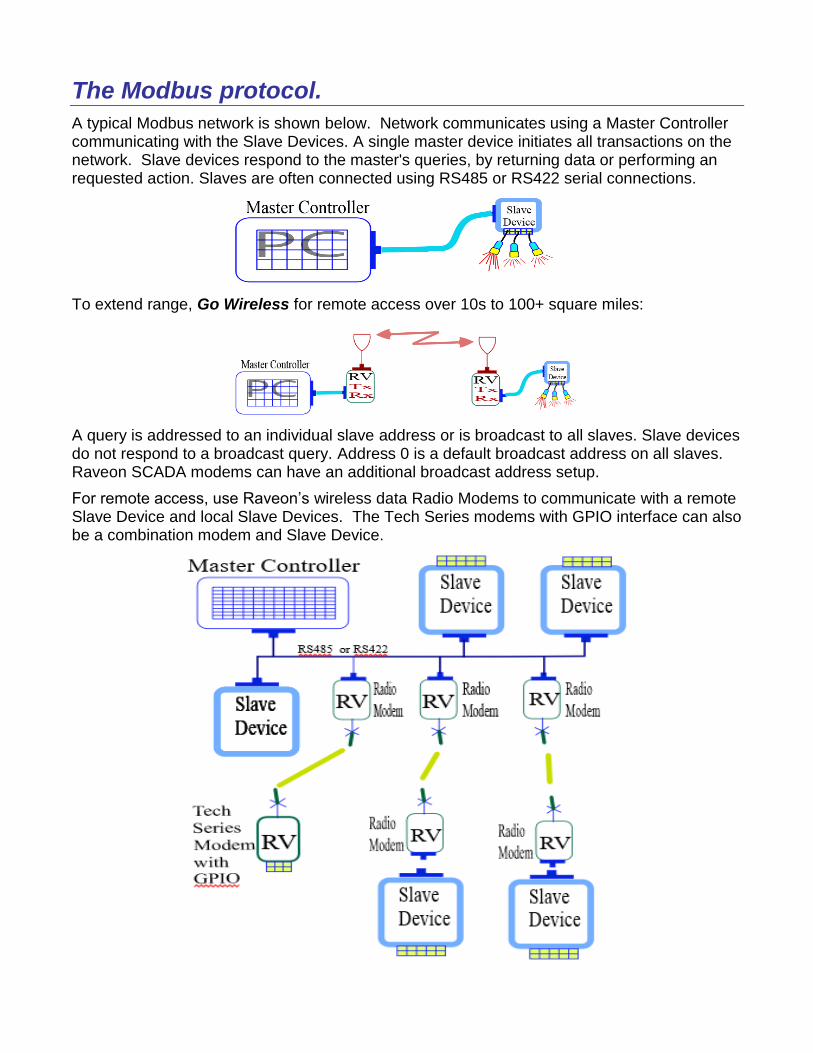
The Modbus protocol.
A typical Modbus network is shown below. Network communicates using a Master Controller communicating with the Slave Devices. A single master device initiates all transactions on the network. Slave devices respond to the master's queries, by returning data or performing an requested action. Slaves are often connected using RS485 or RS422 serial connections.
To extend range, Go Wireless for remote access over 10s to 100+ square miles:
A query is addressed to an individual slave address or is broadcast to all slaves. Slave devices do not respond to a broadcast query. Address 0 is a default broadcast address on all slaves. Raveon SCADA modems can have an additional broadcast address setup.
For remote access, use Raveon’s wireless data Radio Modems to communicate with a remote Slave Device and local Slave Devices. The Tech Series modems with GPIO interface can also be a combination modem and Slave Device.
The MODBUS protocol has 3 standard variants 1)ASCII 2)RTU 3)TCP. Raveon’s radio modems can transfer the MODBUS messages in RTU format and TCP format. The SCADA and telemetry features incorporated into the Raveon radio modems utilize the RTU protocol. When utilizing a radio modem as combination of a slave device and a radio modem the SCADA features of the radio modem must be configured. This document summarizes all SCADA and Telemetry features of the Raveon radio modems.
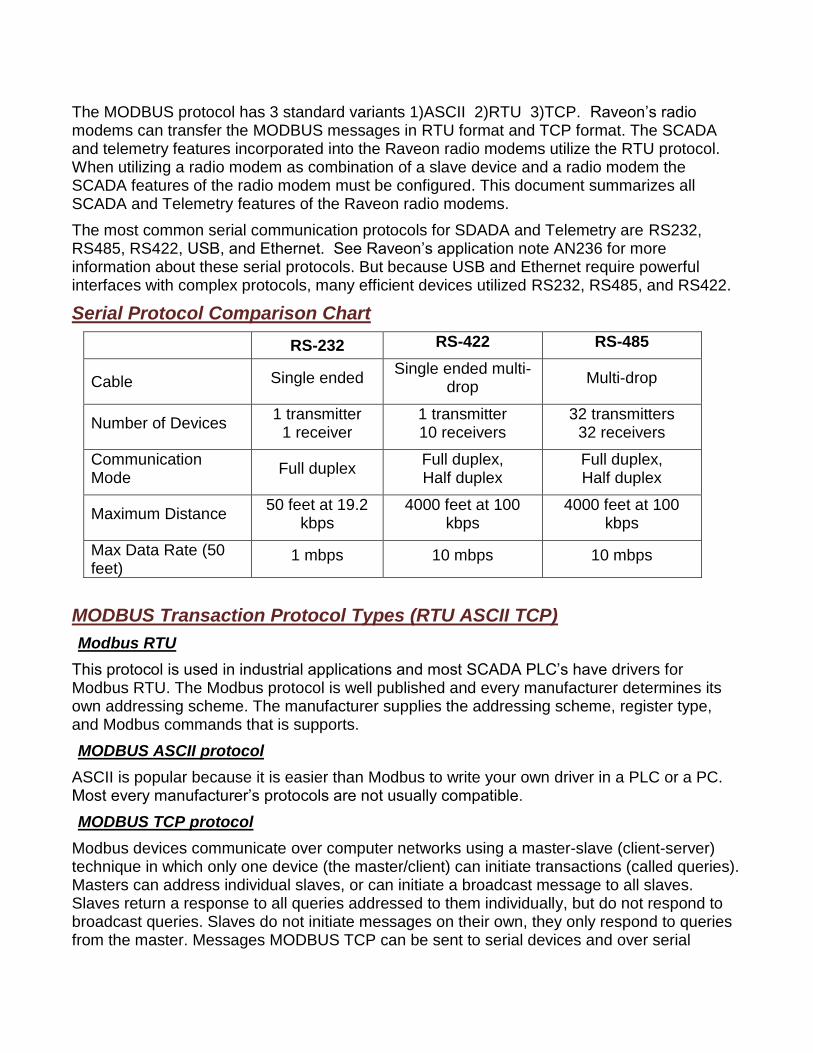
The most common serial communication protocols for SDADA and Telemetry are RS232, RS485, RS422, USB, and Ethernet. See Raveon’s application note AN236 for more information about these serial protocols. But because USB and Ethernet require powerful interfaces with complex protocols, many efficient devices utilized RS232, RS485, and RS422.
Serial Protocol Comparison Chart
RS-232 RS-422 RS-485
Cable Single ended Single ended multi-
drop Multi-drop
Number of Devices 1 transmitter
1 receiver 1 transmitter 10 receivers
32 transmitters 32 receivers
Communication Mode
Full duplex Full duplex, Half duplex
Full duplex, Half duplex
Maximum Distance 50 feet at 19.2
kbps 4000 feet at 100
kbps 4000 feet at 100
kbps
Max Data Rate (50 feet)
1 mbps 10 mbps 10 mbps
MODBUS Transaction Protocol Types (RTU ASCII TCP)
Modbus RTU
This protocol is used in industrial applications and most SCADA PLC’s have drivers for Modbus RTU. The Modbus protocol is well published and every manufacturer determines its own addressing scheme. The manufacturer supplies the addressing scheme, register type, and Modbus commands that is supports.
MODBUS ASCII protocol
ASCII is popular because it is easier than Modbus to write your own driver in a PLC or a PC. Most every manufacturer’s protocols are not usually compatible.
MODBUS TCP protocol
Modbus devices communicate over computer networks using a master-slave (client-server) technique in which only one device (the master/client) can initiate transactions (called queries). Masters can address individual slaves, or can initiate a broadcast message to all slaves. Slaves return a response to all queries addressed to them individually, but do not respond to broadcast queries. Slaves do not initiate messages on their own, they only respond to queries from the master. Messages MODBUS TCP can be sent to serial devices and over serial
modems by using a terminal server to convert the TCP network message to devices with RS232, RS485, or RS422.
Raveon’s Modbus Compatible Devices.
Raveon’s Tech Series radios, model RV-M21, support MODBUS protocol in the version with the General Purpose IO (GPIO) interface and Flexible digital IO (FIO). This feature enables the Tech Series radio to control and read general IO devices without having to purchase a Remote terminal Unit (RTU). The RV-M8 and RV-M6 OEM radio modem modules also can process Modbus messages, so any company desiring to use the Modbus protocol to communicate with wireless devices can utilize Raveon’s OEM modules.
Around the world there are many serial RTU devices that support MODBUS also. It is easy to connect an RTU to a Raveon data radio modem, and issue MODBUS commands over the air to manage the RTU. Save money by using Raveon’s GPIO data radio, but the Tech Series radio modems also have a myriad of IO options that are excellent for connecting to RTUs such as RS232, RS485, and RS422.
Save Cost by Eliminating Slave Devices
Raveon’s Tech Series can operate as radio modems and a Slave Device. In many cases, there is no need for an external slave device to be used instead of just using a Tech Series modem which incorporates many Slave Device features in itself. The General Purpose IO (GPIO) interfaces on Tech Series modems can read and control many remote things.

The message structure of the Modbus RTU function codes is employed in the Tech Series Radios. The data is generally returned in 16 bit integer registers or standard IEEE 32-bit floating point. Data register mapping is unique to devices. This documents contains information about the register mapping of Raveon’s SCADA devices that utilize MODBUS protocol.
MODBUS RTU Commands Modbus is a registered trademark of MODICON, Inc.
Messages sent from devices that utilize SCADA and Telemetry protocols such as MODBUS are often called “Telegrams”.
Big-Endian
Modbus is specified as big-endian, which means the most significant value is at the lowest address. With a read of a 16-bit (single register) value, the 1st byte returned is the MSB (most significant byte) and the 2nd byte returned is the LSB (least significant byte).
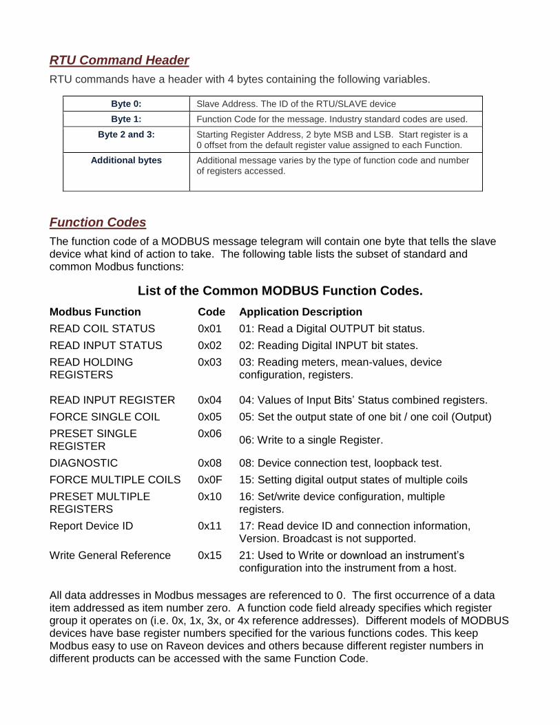
RTU Command Header
RTU commands have a header with 4 bytes containing the following variables.
Byte 0: Slave Address. The ID of the RTU/SLAVE device
Byte 1: Function Code for the message. Industry standard codes are used.
Byte 2 and 3: Starting Register Address, 2 byte MSB and LSB. Start register is a 0 offset from the default register value assigned to each Function.
Additional bytes Additional message varies by the type of function code and number of registers accessed.
Function Codes
The function code of a MODBUS message telegram will contain one byte that tells the slave device what kind of action to take. The following table lists the subset of standard and common Modbus functions:
List of the Common MODBUS Function Codes.
Modbus Function Code Application Description
READ COIL STATUS 0x01 01: Read a Digital OUTPUT bit status.
READ INPUT STATUS 0x02 02: Reading Digital INPUT bit states.
READ HOLDING REGISTERS READ INPUT REGISTER
0x03 0x04
03: Reading meters, mean-values, device configuration, registers. 04: Values of Input Bits’ Status combined registers.
FORCE SINGLE COIL 0x05 05: Set the output state of one bit / one coil (Output)
PRESET SINGLE REGISTER
0x06 06: Write to a single Register.
DIAGNOSTIC 0x08 08: Device connection test, loopback test.
FORCE MULTIPLE COILS 0x0F 15: Setting digital output states of multiple coils
PRESET MULTIPLE REGISTERS
0x10 16: Set/write device configuration, multiple registers.
Report Device ID 0x11 17: Read device ID and connection information, Version. Broadcast is not supported.
Write General Reference 0x15 21: Used to Write or download an instrument’s configuration into the instrument from a host.
All data addresses in Modbus messages are referenced to 0. The first occurrence of a data item addressed as item number zero. A function code field already specifies which register group it operates on (i.e. 0x, 1x, 3x, or 4x reference addresses). Different models of MODBUS devices have base register numbers specified for the various functions codes. This keep Modbus easy to use on Raveon devices and others because different register numbers in different products can be accessed with the same Function Code.
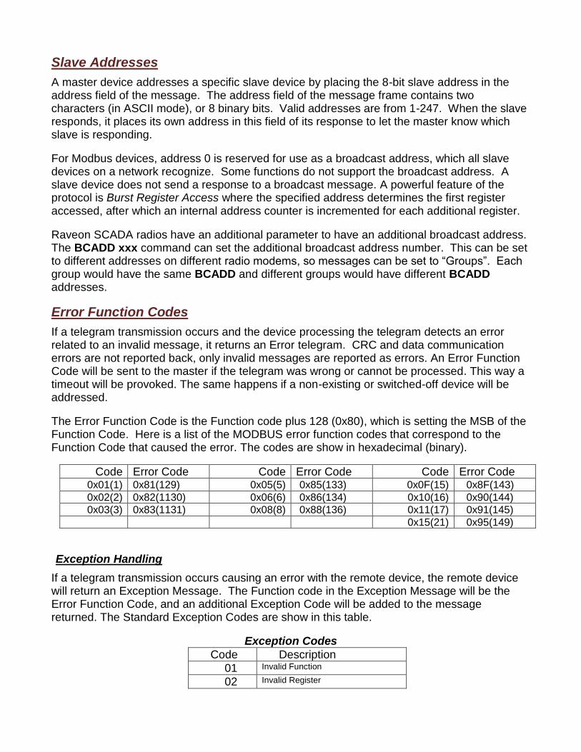
Slave Addresses
A master device addresses a specific slave device by placing the 8-bit slave address in the address field of the message. The address field of the message frame contains two characters (in ASCII mode), or 8 binary bits. Valid addresses are from 1-247. When the slave responds, it places its own address in this field of its response to let the master know which slave is responding.
For Modbus devices, address 0 is reserved for use as a broadcast address, which all slave devices on a network recognize. Some functions do not support the broadcast address. A slave device does not send a response to a broadcast message. A powerful feature of the protocol is Burst Register Access where the specified address determines the first register accessed, after which an internal address counter is incremented for each additional register.
Raveon SCADA radios have an additional parameter to have an additional broadcast address. The BCADD xxx command can set the additional broadcast address number. This can be set to different addresses on different radio modems, so messages can be set to “Groups”. Each group would have the same BCADD and different groups would have different BCADD addresses.
Error Function Codes
If a telegram transmission occurs and the device processing the telegram detects an error related to an invalid message, it returns an Error telegram. CRC and data communication errors are not reported back, only invalid messages are reported as errors. An Error Function Code will be sent to the master if the telegram was wrong or cannot be processed. This way a timeout will be provoked. The same happens if a non-existing or switched-off device will be addressed.
The Error Function Code is the Function code plus 128 (0x80), which is setting the MSB of the Function Code. Here is a list of the MODBUS error function codes that correspond to the Function Code that caused the error. The codes are show in hexadecimal (binary).
Code Error Code Code Error Code Code Error Code 0x01(1) 0x81(129) 0x05(5) 0x85(133) 0x0F(15) 0x8F(143)
0x02(2) 0x82(1130) 0x06(6) 0x86(134) 0x10(16) 0x90(144)
0x03(3) 0x83(1131) 0x08(8) 0x88(136) 0x11(17) 0x91(145)
0x15(21) 0x95(149)
Exception Handling
If a telegram transmission occurs causing an error with the remote device, the remote device will return an Exception Message. The Function code in the Exception Message will be the Error Function Code, and an additional Exception Code will be added to the message returned. The Standard Exception Codes are show in this table.
Exception Codes
Code Description
01 Invalid Function
02 Invalid Register
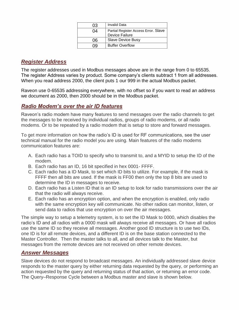
03 Invalid Data
04 Partial Register Access Error. Slave Device Failure
06 Slave Device Busy
09 Buffer Overflow
Register Address
The register addresses used in Modbus messages above are in the range from 0 to 65535. The register Address varies by product. Some company’s clients subtract 1 from all addresses. When you read address 2000, the client puts 1 our 999 in the actual Modbus packet.
Raveon use 0-65535 addressing everywhere, with no offset so if you want to read an address we document as 2000, then 2000 should be in the Modbus packet.
Radio Modem’s over the air ID features
Raveon’s radio modem have many features to send messages over the radio channels to get the messages to be received by individual radios, groups of radio modems, or all radio modems. Or to be repeated by a radio modem that is setup to store and forward messages.
To get more information on how the radio’s ID is used for RF communications, see the user technical manual for the radio model you are using. Main features of the radio modems communication features are:
A. Each radio has a TOID to specify who to transmit to, and a MYID to setup the ID of the modem.
B. Each radio has an ID, 16 bit specified in hex 0001- FFFF. C. Each radio has a ID Mask, to set which ID bits to utilize. For example, if the mask is
FFFF then all bits are used. If the mask is FF00 then only the top 8 bits are used to determine the ID in messages to receive.
D. Each radio has a Listen ID that is an ID setup to look for radio transmissions over the air that the radio will always receive.
E. Each radio has an encryption option, and when the encryption is enabled, only radio with the same encryption key will communicate. No other radios can monitor, listen, or send data to radios that use encryption on over the air messages.
The simple way to setup a telemetry system, is to set the ID Mask to 0000, which disables the radio’s ID and all radios with a 0000 mask will always receive all messages. Or have all radios use the same ID so they receive all messages. Another good ID structure is to use two IDs, one ID is for all remote devices, and a different ID is on the base station connected to the Master Controller. Then the master talks to all, and all devices talk to the Master, but messages from the remote devices are not received on other remote devices.
Answer Messages
Slave devices do not respond to broadcast messages. An individually addressed slave device responds to the master query by either returning data requested by the query, or performing an action requested by the query and returning status of that action, or returning an error code. The Query–Response Cycle between a Modbus master and slave is shown below.
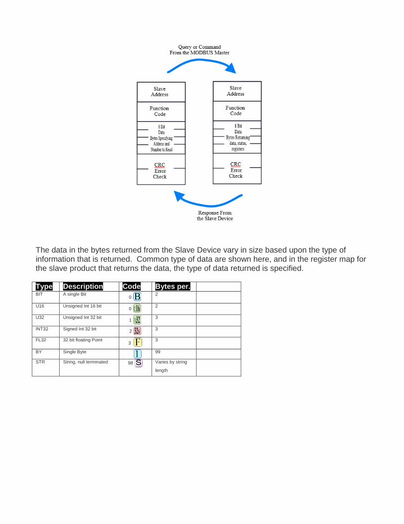
The data in the bytes returned from the Slave Device vary in size based upon the type of information that is returned. Common type of data are shown here, and in the register map for the slave product that returns the data, the type of data returned is specified. Type Description Code Bytes per. BIT A single Bit
0 2
U16 Unsigned Int 16 bit 0
2
U32 Unsigned Int 32 bit 1
3
INT32 Signed Int 32 bit 2
3
FL32 32 bit floating Point 3
3
BY Single Byte
99
STR String, null terminated 98 Varies by string
length
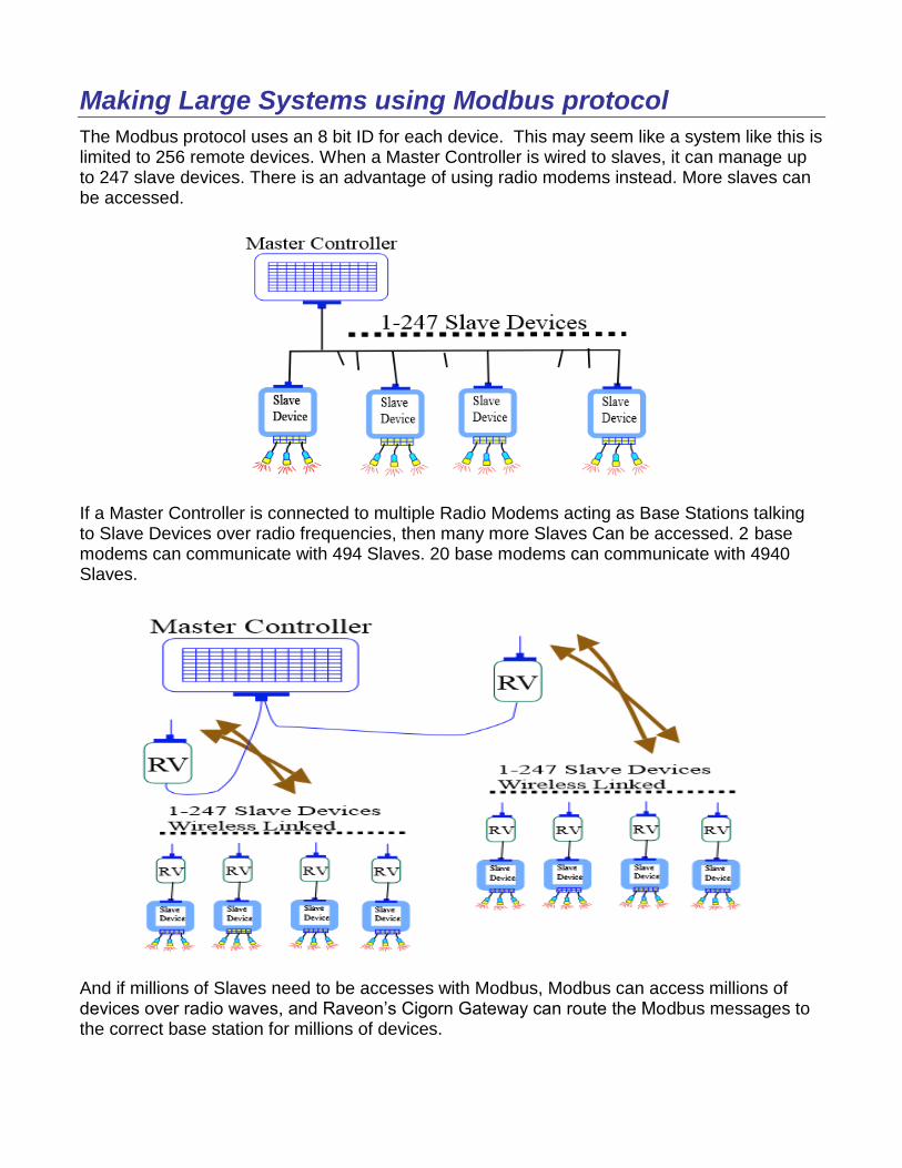
Making Large Systems using Modbus protocol
The Modbus protocol uses an 8 bit ID for each device. This may seem like a system like this is limited to 256 remote devices. When a Master Controller is wired to slaves, it can manage up to 247 slave devices. There is an advantage of using radio modems instead. More slaves can be accessed.
If a Master Controller is connected to multiple Radio Modems acting as Base Stations talking to Slave Devices over radio frequencies, then many more Slaves Can be accessed. 2 base modems can communicate with 494 Slaves. 20 base modems can communicate with 4940 Slaves.
And if millions of Slaves need to be accesses with Modbus, Modbus can access millions of devices over radio waves, and Raveon’s Cigorn Gateway can route the Modbus messages to the correct base station for millions of devices.
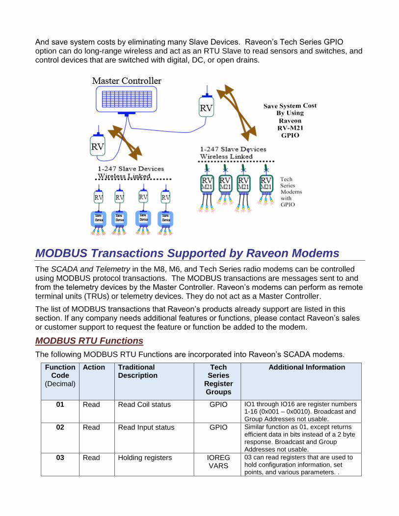
And save system costs by eliminating many Slave Devices. Raveon’s Tech Series GPIO option can do long-range wireless and act as an RTU Slave to read sensors and switches, and control devices that are switched with digital, DC, or open drains.
MODBUS Transactions Supported by Raveon Modems
The SCADA and Telemetry in the M8, M6, and Tech Series radio modems can be controlled using MODBUS protocol transactions. The MODBUS transactions are messages sent to and from the telemetry devices by the Master Controller. Raveon’s modems can perform as remote terminal units (TRUs) or telemetry devices. They do not act as a Master Controller.
The list of MODBUS transactions that Raveon’s products already support are listed in this section. If any company needs additional features or functions, please contact Raveon’s sales or customer support to request the feature or function be added to the modem.
MODBUS RTU Functions
The following MODBUS RTU Functions are incorporated into Raveon’s SCADA modems.
Function Code
(Decimal)
Action Traditional Description
Tech Series
Register Groups
Additional Information
01 Read Read Coil status GPIO IO1 through IO16 are register numbers 1-16 (0x001 – 0x0010). Broadcast and Group Addresses not usable.
02 Read Read Input status GPIO Similar function as 01, except returns efficient data in bits instead of a 2 byte response. Broadcast and Group Addresses not usable.
03 Read Holding registers IOREG VARS
03 can read registers that are used to hold configuration information, set points, and various parameters. .
Broadcast and Group Addresses not usable.
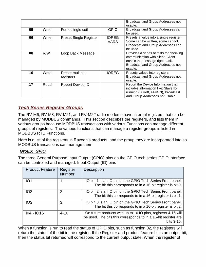
05 Write Force single coil GPIO Broadcast and Group Addresses can be used.
06 Write Preset Single Register IOREG VARS
Presets a value into a single register. Some can be written, some cannot. Broadcast and Group Addresses can be used.
08 R/W Loop Back Message Provides a series of tests for checking communication with client. Client echo’s the message right back. Broadcast and Group Addresses not usable.
16 Write Preset multiple registers
IOREG Presets values into registers. Broadcast and Group Addresses not usable.
17 Read Report Device ID Report the Device Information that includes information like: Slave ID, running (00=off, FF=ON), Broadcast and Group Addresses not usable.
Tech Series Register Groups
The RV-M6, RV-M8, RV-M21, and RV-M22 radio modems have internal registers that can be managed by MODBUS commands. This section describes the registers, and lists them in various groups because MODBUS transactions with various Functions can manage different groups of registers. The various functions that can manage a register groups is listed in MODBUS RTU Functions.
Here is a list of the registers in Raveon’s products, and the group they are incorporated into so MODBUS transactions can manage them.
Group: GPIO
The three General Purpose Input Output (GPIO) pins on the GPIO tech series GPIO interface can be controlled and managed. Input Output (IO) pins
Product Feature Register Number
Description
IO1 1 IO pin 1 is an IO pin on the GPIO Tech Series Front panel. The bit this corresponds to in a 16-bit register is bit 0.
IO2 2 IO pin 2 is an IO pin on the GPIO Tech Series Front panel. The bit this corresponds to in a 16-bit register is bit 1.
IO3 3 IO pin 3 is an IO pin on the GPIO Tech Series Front panel. The bit this corresponds to in a 16-bit register is bit 2.
I04 - IO16 4-16 On future products with up to 16 IO pins, registers 4-16 will be used. The bits this corresponds to in a 16-bit register are
bits 3-15.
When a function is run to read the status of GPIO bits, such as function 02, the registers will return the status of the bit in the register. If the Register and product feature bit is an output bit, then the status bit returned will correspond to the current output state. When the register of
product feature bit is an input bit, the status bit returned will be the current input status of the input put.
Group: IOREG
The GPIO pins on the GPIO tech series GPIO interface have registers in the radio modem that holds their state, and other information related to the IO pins such as timers and counters. The IOREG group are registers that hold and manage the IO pins and their various features. Most registers are 16 bits (2 bytes). Even though GPIO Tech Series interface only has a few IO pins, the registers are designed to manage up to 16 bits per radio modem.
Up Count Register: Counts digital changes to the Input bit. Every time the bit changes from 0 to 1, the Up Count register for the bit ticks up. The first Register Number is for GPIO IO1 input (bit 0). The next 15 registers are for the next 15 input bits. Tech Series GPIO has only 3 input bits, so use registers 2200, 2201, 2202 are used to access them.
Group: VARS (VARIABLES)
The Tech Series radio modems have a variety of variables stored in registers that can be read using MODBUS and some can be modified and reconfigured using MODBUS.
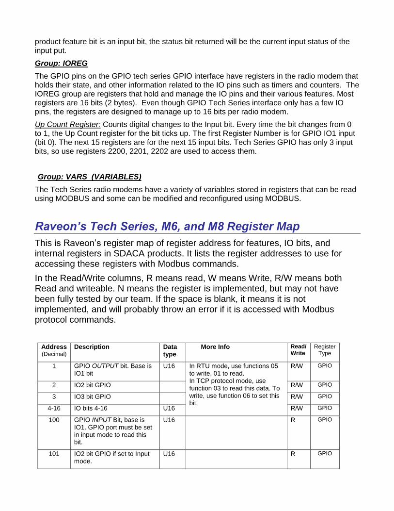
Raveon’s Tech Series, M6, and M8 Register Map
This is Raveon’s register map of register address for features, IO bits, and internal registers in SDACA products. It lists the register addresses to use for accessing these registers with Modbus commands.
In the Read/Write columns, R means read, W means Write, R/W means both Read and writeable. N means the register is implemented, but may not have been fully tested by our team. If the space is blank, it means it is not implemented, and will probably throw an error if it is accessed with Modbus protocol commands.
Address (Decimal)
Description Data type
More Info Read/Write
Register Type
1 GPIO OUTPUT bit. Base is IO1 bit
U16 In RTU mode, use functions 05 to write, 01 to read. In TCP protocol mode, use function 03 to read this data. To write, use function 06 to set this bit.
R/W GPIO
2 IO2 bit GPIO R/W GPIO
3 IO3 bit GPIO R/W GPIO
4-16 IO bits 4-16 U16 R/W GPIO
100 GPIO INPUT Bit, base is IO1. GPIO port must be set in input mode to read this bit.
U16 R GPIO
101 IO2 bit GPIO if set to Input mode.
U16 R GPIO
102 IO3 bit GPIO if set to input mode.
U16 R GPIO
103-115 IO bits 4-16 if set to input mode.
U16 R GPIO
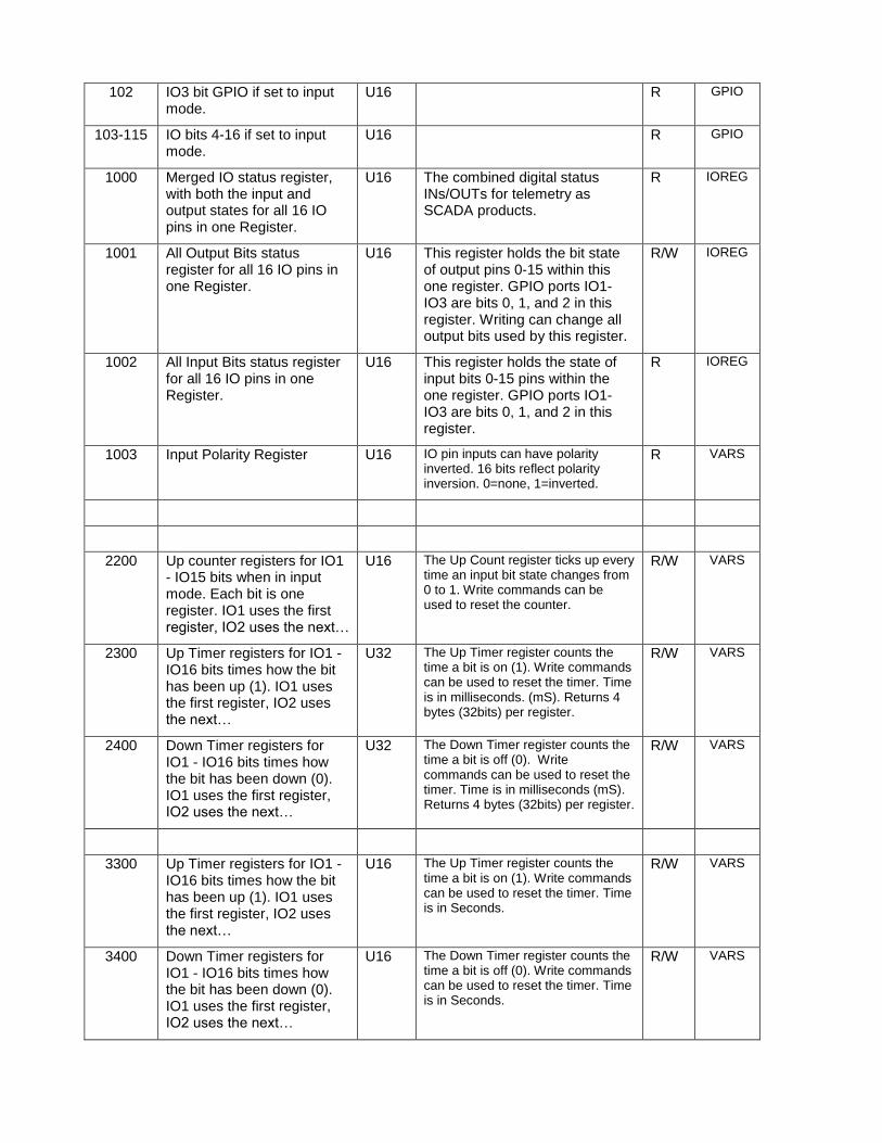
1000 Merged IO status register, with both the input and output states for all 16 IO pins in one Register.
U16 The combined digital status INs/OUTs for telemetry as SCADA products.
R IOREG
1001 All Output Bits status register for all 16 IO pins in one Register.
U16 This register holds the bit state of output pins 0-15 within this one register. GPIO ports IO1-IO3 are bits 0, 1, and 2 in this register. Writing can change all output bits used by this register.
R/W IOREG
1002 All Input Bits status register for all 16 IO pins in one Register.
U16 This register holds the state of input bits 0-15 pins within the one register. GPIO ports IO1-IO3 are bits 0, 1, and 2 in this register.
R IOREG
1003 Input Polarity Register U16 IO pin inputs can have polarity inverted. 16 bits reflect polarity inversion. 0=none, 1=inverted.
R VARS
2200 Up counter registers for IO1 - IO15 bits when in input mode. Each bit is one register. IO1 uses the first register, IO2 uses the next…
U16 The Up Count register ticks up every time an input bit state changes from 0 to 1. Write commands can be used to reset the counter.
R/W VARS
2300 Up Timer registers for IO1 - IO16 bits times how the bit has been up (1). IO1 uses the first register, IO2 uses the next…
U32 The Up Timer register counts the time a bit is on (1). Write commands can be used to reset the timer. Time is in milliseconds. (mS). Returns 4 bytes (32bits) per register.
R/W VARS
2400 Down Timer registers for IO1 - IO16 bits times how the bit has been down (0). IO1 uses the first register, IO2 uses the next…
U32 The Down Timer register counts the time a bit is off (0). Write commands can be used to reset the timer. Time is in milliseconds (mS). Returns 4 bytes (32bits) per register.
R/W VARS
3300 Up Timer registers for IO1 - IO16 bits times how the bit has been up (1). IO1 uses the first register, IO2 uses the next…
U16 The Up Timer register counts the time a bit is on (1). Write commands can be used to reset the timer. Time is in Seconds.
R/W VARS
3400 Down Timer registers for IO1 - IO16 bits times how the bit has been down (0). IO1 uses the first register, IO2 uses the next…
U16 The Down Timer register counts the time a bit is off (0). Write commands can be used to reset the timer. Time is in Seconds.
R/W VARS
R/W
R/W
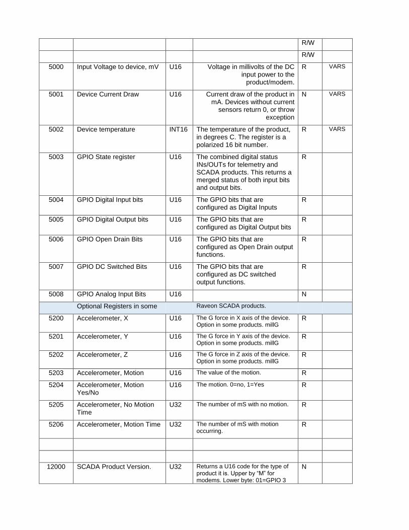
5000 Input Voltage to device, mV U16 Voltage in millivolts of the DC input power to the
product/modem.
R VARS
5001 Device Current Draw U16 Current draw of the product in mA. Devices without current
sensors return 0, or throw exception
N VARS
5002 Device temperature INT16 The temperature of the product, in degrees C. The register is a polarized 16 bit number.
R VARS
5003 GPIO State register U16 The combined digital status INs/OUTs for telemetry and SCADA products. This returns a merged status of both input bits and output bits.
R
5004 GPIO Digital Input bits U16 The GPIO bits that are configured as Digital Inputs
R
5005 GPIO Digital Output bits U16 The GPIO bits that are configured as Digital Output bits
R
5006 GPIO Open Drain Bits U16 The GPIO bits that are configured as Open Drain output functions.
R
5007 GPIO DC Switched Bits U16 The GPIO bits that are configured as DC switched output functions.
R
5008 GPIO Analog Input Bits U16 N
Optional Registers in some Raveon SCADA products.
5200 Accelerometer, X U16 The G force in X axis of the device. Option in some products. millG
R
5201 Accelerometer, Y U16 The G force in Y axis of the device. Option in some products. millG
R
5202 Accelerometer, Z U16 The G force in Z axis of the device. Option in some products. millG
R
5203 Accelerometer, Motion U16 The value of the motion. R
5204 Accelerometer, Motion Yes/No
U16 The motion. 0=no, 1=Yes R
5205 Accelerometer, No Motion Time
U32 The number of mS with no motion. R
5206 Accelerometer, Motion Time U32 The number of mS with motion occurring.
R
12000 SCADA Product Version. U32 Returns a U16 code for the type of product it is. Upper by “M” for modems. Lower byte: 01=GPIO 3
N
bit.
12290 Read Firmware Version information.
U32 Returns 4 bytes N
MODBUS RTU Communication
All MODBUS requests sent via RTU use serial ports. The standard data type is Byte (8-Bit) and Register (16-Bit). Registers are transmitted with the high byte first, followed by the low byte.
The MODEBUS RTU link layer includes the following properties/behaviors:
A. Slave address recognition, B. Start / End of Frame detection, C. CRC-16 generation / checking, D. Transmit / receive message time-out, E. Buffer overflow detection, F. Framing error detection, G. Idle line detection.
Communication errors detected by the link layer in messages received by the slave are ignored and the device automatically restarts by initiating a new receive on the next idle line detection.
Slave Address
MODBUS devices need to be assigned a SLAVE address. The Radio Modems have a command in them ___ that is used to set the modems “Slave Address” The modem will respond to MODBUS telegrams only when the Slave Address in the telegram matches the modem’s Slave Address.
Raveon modem have radio IDs in them. These are for RF communications, but have nothing to do with the MODBUS telegrams.
RTU request and response messages are prefixed by six bytes.
Modbus uses Big Endian byte orientation, where the Most Significant Byte (MSB) is the first byte and Lease Significant Byte (LCB) is the second byte. The last two bytes of the message is the CRC. It is stored in little Endian (LSB first, MSB last)
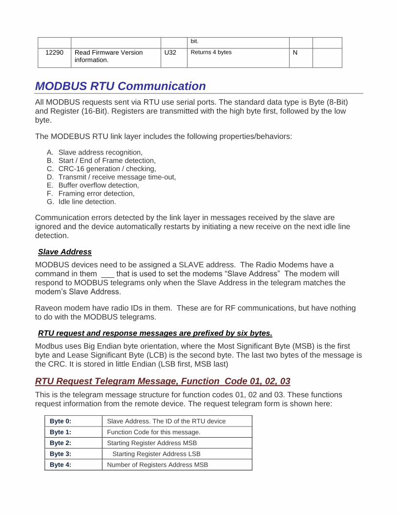
RTU Request Telegram Message, Function Code 01, 02, 03
This is the telegram message structure for function codes 01, 02 and 03. These functions request information from the remote device. The request telegram form is shown here:
Byte 0: Slave Address. The ID of the RTU device
Byte 1: Function Code for this message.
Byte 2: Starting Register Address MSB
Byte 3: Starting Register Address LSB
Byte 4: Number of Registers Address MSB
Byte 5: Number of Registers Address LSB
Byte 6: Error Check Low Byte
Byte 7: Error Check High Byte
RTU Answer Telegram Message from a previous Request 01, 02, 03
When a device answers a telegram of function 01, 02, or 03, the message (telegram) response structure is as follows.
Byte 0: Slave Address. The ID of the RTU device
Byte 1: Function Code for this message.
Byte 2: Number of data bytes (N)
Byte 3: Byte #1
Byte 3+N: Byte #2 (Optional based on data number N)
Byte 3+N: Byte #3 (Optional based on data number N)
Byte 3+N: Byte #4 (Optional based on data number N)
Byte 3+N: Byte #5 (Optional based on data number N)
Byte 4+N: Error Check Low Byte
Byte 5+N: Error Check High Byte
A unique feature of Raveon’s SCADA radios is, some registers are accessible via two different register numbers. One register will always respond when it gets a telegram to manage it. And a second register with the same features and coils is available to manage the same register and the second register will not send a response message so it will save bandwidth. The user may choose which register to communicate with.
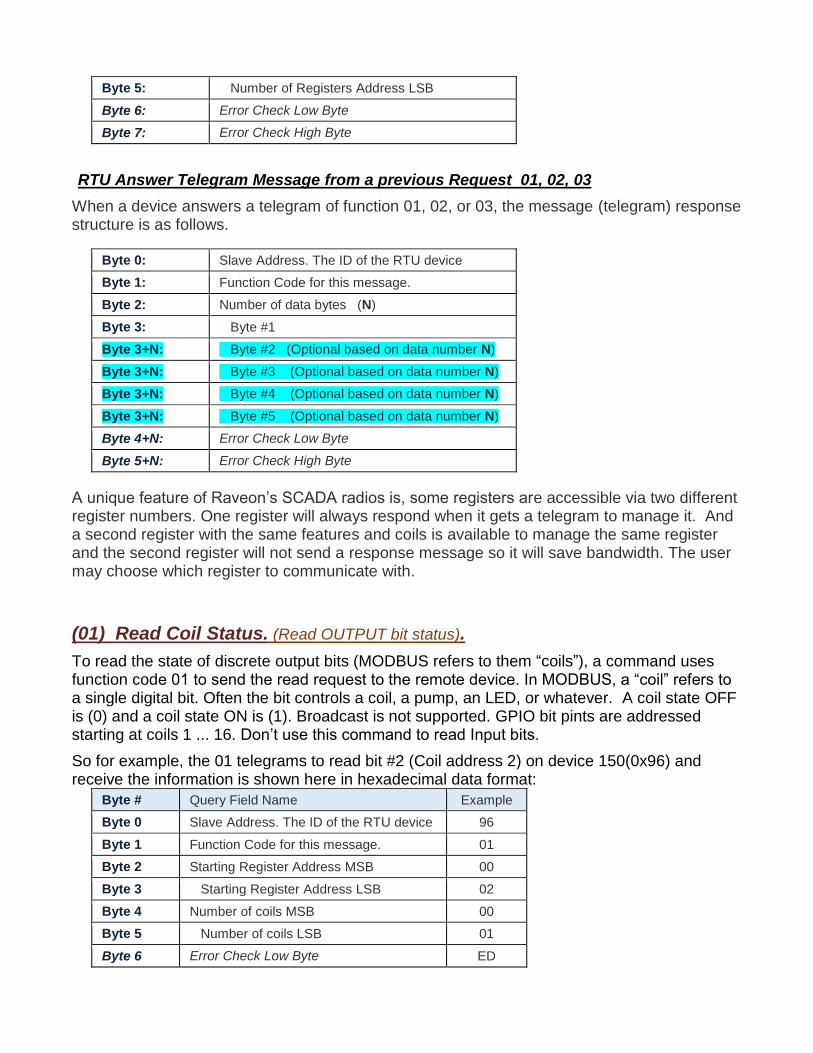
(01) Read Coil Status. (Read OUTPUT bit status).
To read the state of discrete output bits (MODBUS refers to them “coils”), a command uses function code 01 to send the read request to the remote device. In MODBUS, a “coil” refers to a single digital bit. Often the bit controls a coil, a pump, an LED, or whatever. A coil state OFF is (0) and a coil state ON is (1). Broadcast is not supported. GPIO bit pints are addressed starting at coils 1 ... 16. Don’t use this command to read Input bits.
So for example, the 01 telegrams to read bit #2 (Coil address 2) on device 150(0x96) and receive the information is shown here in hexadecimal data format:
Byte # Query Field Name Example
Byte 0 Slave Address. The ID of the RTU device 96
Byte 1 Function Code for this message. 01
Byte 2 Starting Register Address MSB 00
Byte 3 Starting Register Address LSB 02
Byte 4 Number of coils MSB 00
Byte 5 Number of coils LSB 01
Byte 6 Error Check Low Byte ED

Byte 7 Error Check High Byte 40
The coil status in the response message is setup as one coil per bit of the Data Byte field. Status is indicated as: 1 = ON; 0 = OFF. The LSB of the first data byte contains the coil addressed in the query. The other coils follow toward the high order end of this byte, and from low order to high order in subsequent bytes.
Of more than 8 coils are read, additional data bytes are included. The first byte 1, is coils 1-8, the second byte would be coils 9-16 if the product had that many coils and the request was larger than 8.
The structure of the 01 Read Coil Status response is:
Byte # Query Field Name Example
Byte 0 Slave Address. The ID of the RTU device 96
Byte 1 Function Code for this message. 02 01
Byte 2 Byte Count (N) 01
Data Byte 1 The MSB response Data bytes containing the requested output bits status. Bit 0 is
00
2 CRC Bytes Error Check (LSB first) D18D
Request: 96 01 00 02 00 01 40 ED Response: 96 01 01 00 7D FC (it reported that coil 2 is OFF)
Current RV-M21 GPIO utilized up to 3 coils. Future products may incorporate more. Any request to read from 1-16 coils will responded with up to 16 bits. Requests for more than 16 are invalid, and the response will only return 16 bits (2bytes) in the RV-M21.
(02) Read Discrete Inputs (Input Bit status loaded into Bytes).
To read the state of input bits, a command uses function code 02 to send the read request to the remote device.
This function is used to read contiguous status of discrete inputs in a remote device. The request specifies the starting address (the address of the first input specified), and the number of inputs to report. In the PDU Discrete Inputs are addressed starting at zero.
So for example, the 02 function telegrams to read 3 coils IO1-IO3 on device 150(0x96) and receive the information is shown here in hexadecimal data format:
Byte # Query Field Name Example
Byte 0 Slave Address. The ID of the RTU device 96
Byte 1 Function Code for this message. 02
Byte 2 Starting Register Address MSB 00
Byte 3 Starting Register Address LSB 01
Byte 4 Number of coils MSB 00
Byte 5 Number of coils LSB 03
Byte 6 Error Check Low Byte 75
Byte 7 Error Check High Byte 2C
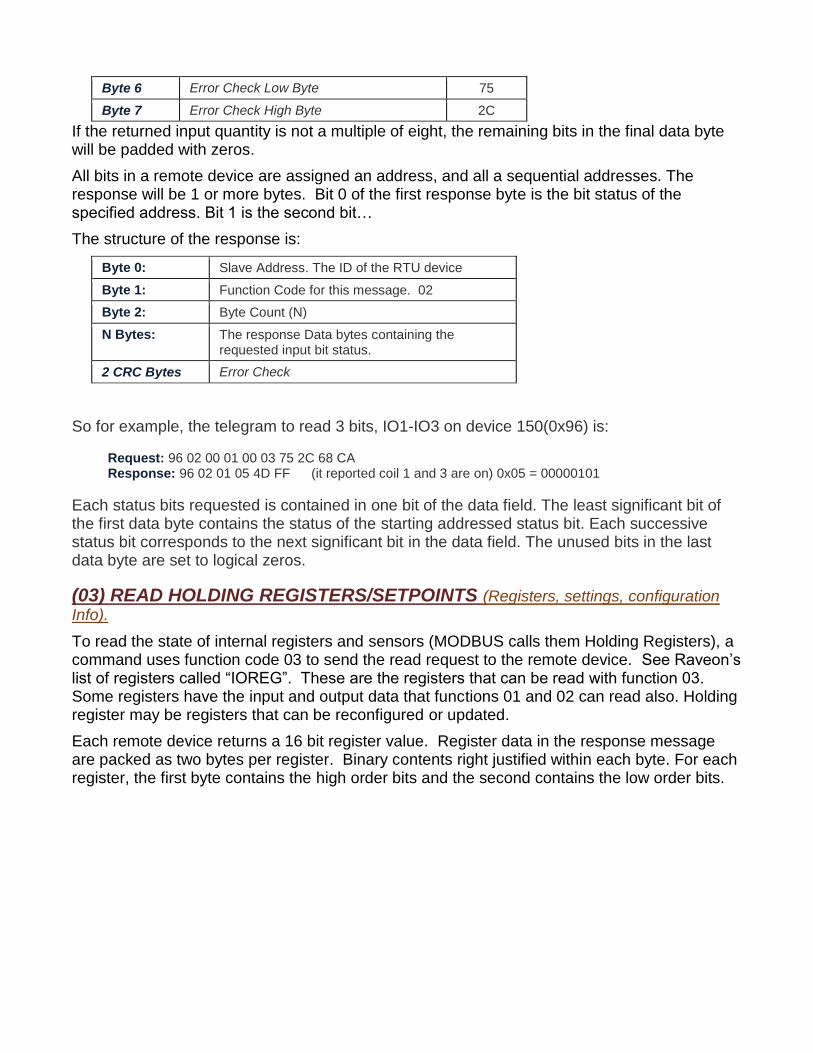
If the returned input quantity is not a multiple of eight, the remaining bits in the final data byte will be padded with zeros.
All bits in a remote device are assigned an address, and all a sequential addresses. The response will be 1 or more bytes. Bit 0 of the first response byte is the bit status of the specified address. Bit 1 is the second bit…
The structure of the response is:
Byte 0: Slave Address. The ID of the RTU device
Byte 1: Function Code for this message. 02
Byte 2: Byte Count (N)
N Bytes: The response Data bytes containing the requested input bit status.
2 CRC Bytes Error Check
So for example, the telegram to read 3 bits, IO1-IO3 on device 150(0x96) is:
Request: 96 02 00 01 00 03 75 2C 68 CA Response: 96 02 01 05 4D FF (it reported coil 1 and 3 are on) 0x05 = 00000101
Each status bits requested is contained in one bit of the data field. The least significant bit of the first data byte contains the status of the starting addressed status bit. Each successive status bit corresponds to the next significant bit in the data field. The unused bits in the last data byte are set to logical zeros.
(03) READ HOLDING REGISTERS/SETPOINTS (Registers, settings, configuration
Info).
To read the state of internal registers and sensors (MODBUS calls them Holding Registers), a command uses function code 03 to send the read request to the remote device. See Raveon’s list of registers called “IOREG”. These are the registers that can be read with function 03. Some registers have the input and output data that functions 01 and 02 can read also. Holding register may be registers that can be reconfigured or updated.
Each remote device returns a 16 bit register value. Register data in the response message are packed as two bytes per register. Binary contents right justified within each byte. For each register, the first byte contains the high order bits and the second contains the low order bits.
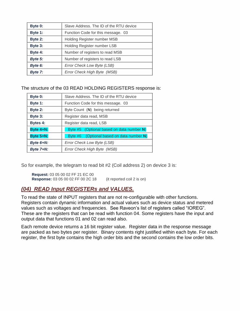
Byte 0: Slave Address. The ID of the RTU device
Byte 1: Function Code for this message. 03
Byte 2: Holding Register number MSB
Byte 3: Holding Register number LSB
Byte 4: Number of registers to read MSB
Byte 5: Number of registers to read LSB
Byte 6: Error Check Low Byte (LSB)
Byte 7: Error Check High Byte (MSB)
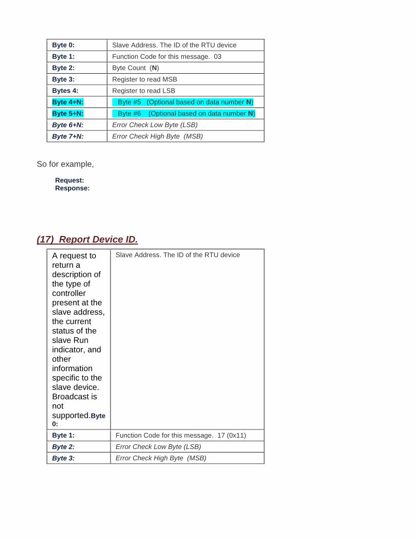
The structure of the 03 READ HOLDING REGISTERS response is:
Byte 0: Slave Address. The ID of the RTU device
Byte 1: Function Code for this message. 03
Byte 2: Byte Count (N) being returned
Byte 3: Register data read, MSB
Bytes 4: Register data read, LSB
Byte 4+N: Byte #5 (Optional based on data number N)
Byte 5+N: Byte #6 (Optional based on data number N)
Byte 6+N: Error Check Low Byte (LSB)
Byte 7+N: Error Check High Byte (MSB)
So for example, the telegram to read bit #2 (Coil address 2) on device 3 is:
Request: 03 05 00 02 FF 21 EC 00 Response: 03 05 00 02 FF 00 2C 18 (it reported coil 2 is on)
(04) READ Input REGISTERs and VALUES.
To read the state of INPUT registers that are not re-configurable with other functions. Registers contain dynamic information and actual values such as device status and metered values such as voltages and frequencies. See Raveon’s list of registers called “IOREG”. These are the registers that can be read with function 04. Some registers have the input and output data that functions 01 and 02 can read also.
Each remote device returns a 16 bit register value. Register data in the response message are packed as two bytes per register. Binary contents right justified within each byte. For each register, the first byte contains the high order bits and the second contains the low order bits.
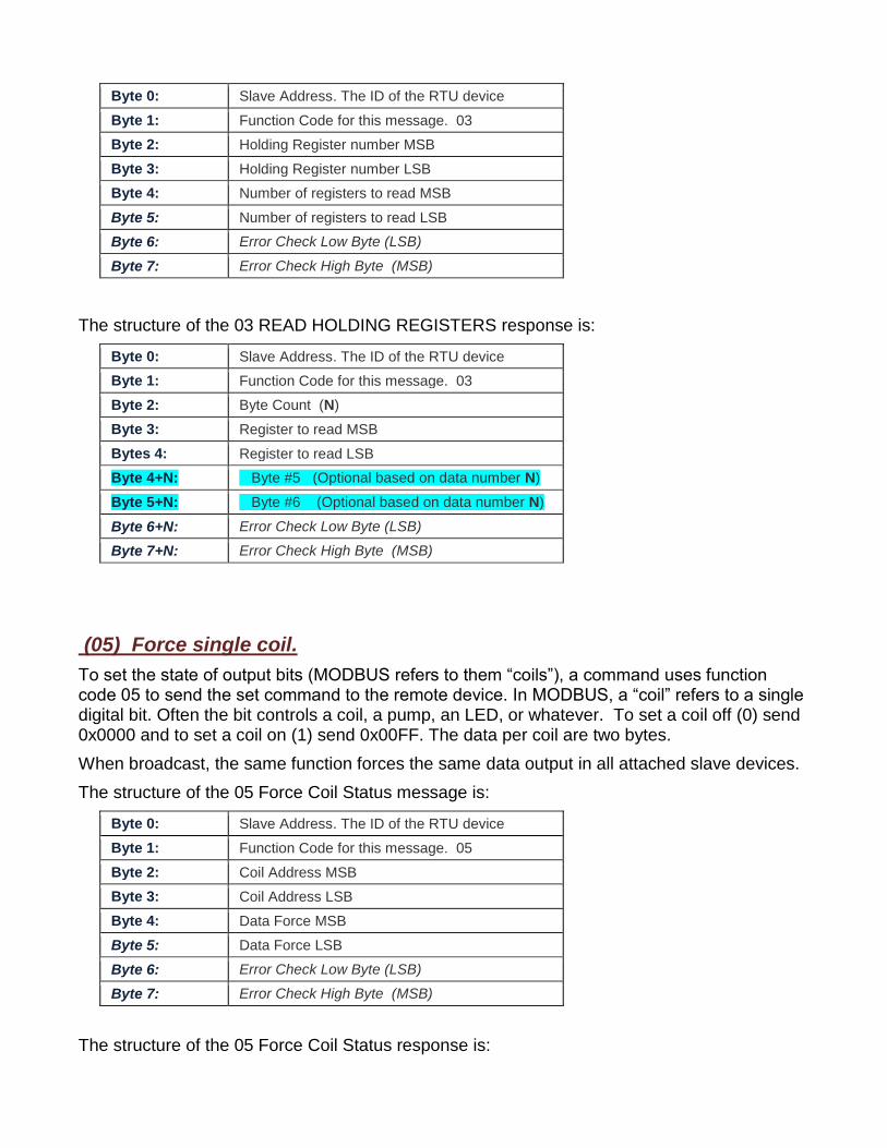
Byte 0: Slave Address. The ID of the RTU device
Byte 1: Function Code for this message. 03
Byte 2: Holding Register number MSB
Byte 3: Holding Register number LSB
Byte 4: Number of registers to read MSB
Byte 5: Number of registers to read LSB
Byte 6: Error Check Low Byte (LSB)
Byte 7: Error Check High Byte (MSB)
The structure of the 03 READ HOLDING REGISTERS response is:
Byte 0: Slave Address. The ID of the RTU device
Byte 1: Function Code for this message. 03
Byte 2: Byte Count (N)
Byte 3: Register to read MSB
Bytes 4: Register to read LSB
Byte 4+N: Byte #5 (Optional based on data number N)
Byte 5+N: Byte #6 (Optional based on data number N)
Byte 6+N: Error Check Low Byte (LSB)
Byte 7+N: Error Check High Byte (MSB)
(05) Force single coil.
To set the state of output bits (MODBUS refers to them “coils”), a command uses function code 05 to send the set command to the remote device. In MODBUS, a “coil” refers to a single digital bit. Often the bit controls a coil, a pump, an LED, or whatever. To set a coil off (0) send 0x0000 and to set a coil on (1) send 0x00FF. The data per coil are two bytes.
When broadcast, the same function forces the same data output in all attached slave devices.
The structure of the 05 Force Coil Status message is:
Byte 0: Slave Address. The ID of the RTU device
Byte 1: Function Code for this message. 05
Byte 2: Coil Address MSB
Byte 3: Coil Address LSB
Byte 4: Data Force MSB
Byte 5: Data Force LSB
Byte 6: Error Check Low Byte (LSB)
Byte 7: Error Check High Byte (MSB)
The structure of the 05 Force Coil Status response is:
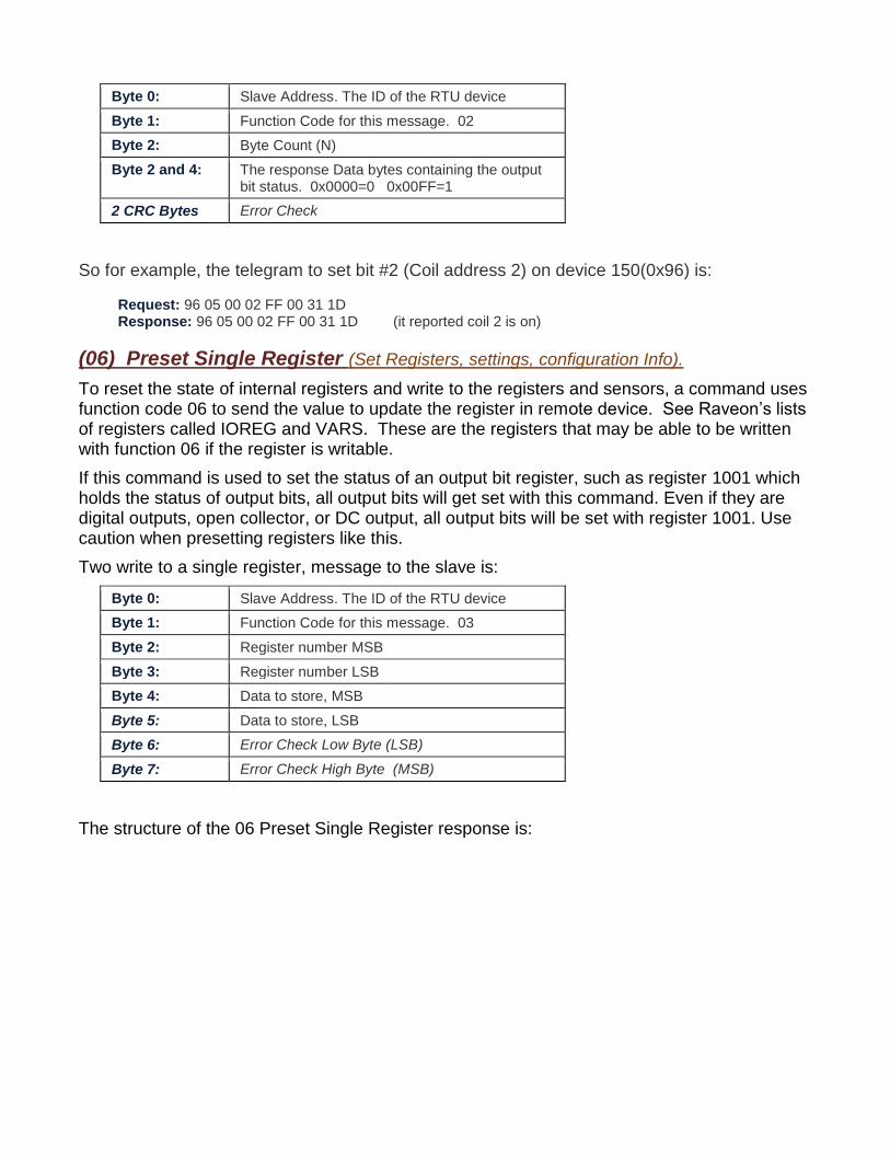
Byte 0: Slave Address. The ID of the RTU device
Byte 1: Function Code for this message. 02
Byte 2: Byte Count (N)
Byte 2 and 4: The response Data bytes containing the output bit status. 0x0000=0 0x00FF=1
2 CRC Bytes Error Check
So for example, the telegram to set bit #2 (Coil address 2) on device 150(0x96) is:
Request: 96 05 00 02 FF 00 31 1D Response: 96 05 00 02 FF 00 31 1D (it reported coil 2 is on)
(06) Preset Single Register (Set Registers, settings, configuration Info).
To reset the state of internal registers and write to the registers and sensors, a command uses function code 06 to send the value to update the register in remote device. See Raveon’s lists of registers called IOREG and VARS. These are the registers that may be able to be written with function 06 if the register is writable.
If this command is used to set the status of an output bit register, such as register 1001 which holds the status of output bits, all output bits will get set with this command. Even if they are digital outputs, open collector, or DC output, all output bits will be set with register 1001. Use caution when presetting registers like this.
Two write to a single register, message to the slave is:
Byte 0: Slave Address. The ID of the RTU device
Byte 1: Function Code for this message. 03
Byte 2: Register number MSB
Byte 3: Register number LSB
Byte 4: Data to store, MSB
Byte 5: Data to store, LSB
Byte 6: Error Check Low Byte (LSB)
Byte 7: Error Check High Byte (MSB)
The structure of the 06 Preset Single Register response is:
Byte 0: Slave Address. The ID of the RTU device
Byte 1: Function Code for this message. 03
Byte 2: Byte Count (N)
Byte 3: Register to read MSB
Bytes 4: Register to read LSB
Byte 4+N: Byte #5 (Optional based on data number N)
Byte 5+N: Byte #6 (Optional based on data number N)
Byte 6+N: Error Check Low Byte (LSB)
Byte 7+N: Error Check High Byte (MSB)
So for example,
Request: Response:
(17) Report Device ID.
A request to return a description of the type of controller present at the slave address, the current status of the slave Run indicator, and other information specific to the slave device. Broadcast is not supported.Byte
0:
Slave Address. The ID of the RTU device
Byte 1: Function Code for this message. 17 (0x11)
Byte 2: Error Check Low Byte (LSB)
Byte 3: Error Check High Byte (MSB)
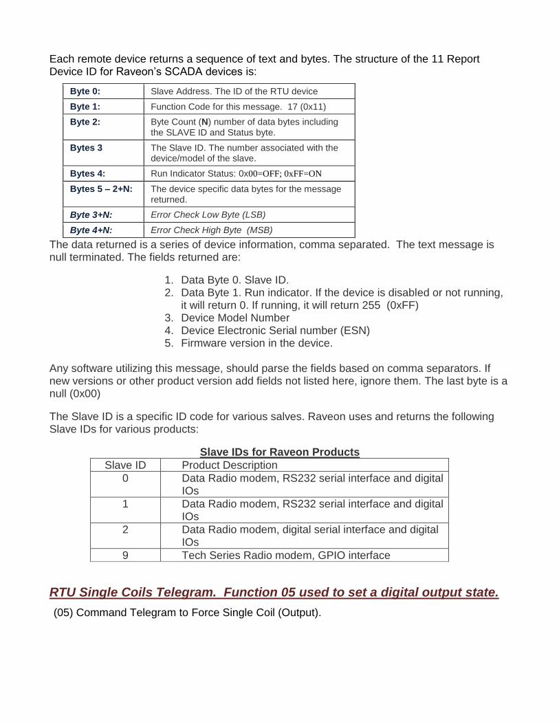
Each remote device returns a sequence of text and bytes. The structure of the 11 Report Device ID for Raveon’s SCADA devices is:
Byte 0: Slave Address. The ID of the RTU device
Byte 1: Function Code for this message. 17 (0x11)
Byte 2: Byte Count (N) number of data bytes including the SLAVE ID and Status byte.
Bytes 3 The Slave ID. The number associated with the device/model of the slave.
Bytes 4: Run Indicator Status: 0x00=OFF; 0xFF=ON
Bytes 5 – 2+N: The device specific data bytes for the message returned.
Byte 3+N: Error Check Low Byte (LSB)
Byte 4+N: Error Check High Byte (MSB)
The data returned is a series of device information, comma separated. The text message is null terminated. The fields returned are:
1. Data Byte 0. Slave ID. 2. Data Byte 1. Run indicator. If the device is disabled or not running,
it will return 0. If running, it will return 255 (0xFF) 3. Device Model Number 4. Device Electronic Serial number (ESN) 5. Firmware version in the device.
Any software utilizing this message, should parse the fields based on comma separators. If new versions or other product version add fields not listed here, ignore them. The last byte is a null (0x00)
The Slave ID is a specific ID code for various salves. Raveon uses and returns the following Slave IDs for various products:
Slave IDs for Raveon Products
Slave ID Product Description
0 Data Radio modem, RS232 serial interface and digital IOs
1 Data Radio modem, RS232 serial interface and digital IOs
2 Data Radio modem, digital serial interface and digital IOs
9 Tech Series Radio modem, GPIO interface
RTU Single Coils Telegram. Function 05 used to set a digital output state.
(05) Command Telegram to Force Single Coil (Output).
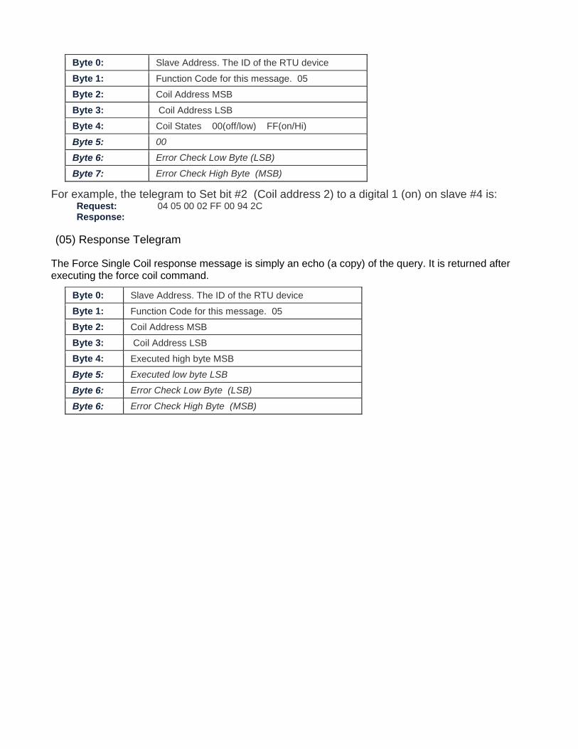
Byte 0: Slave Address. The ID of the RTU device
Byte 1: Function Code for this message. 05
Byte 2: Coil Address MSB
Byte 3: Coil Address LSB
Byte 4: Coil States 00(off/low) FF(on/Hi)
Byte 5: 00
Byte 6: Error Check Low Byte (LSB)
Byte 7: Error Check High Byte (MSB)
For example, the telegram to Set bit #2 (Coil address 2) to a digital 1 (on) on slave #4 is: Request: 04 05 00 02 FF 00 94 2C Response:
(05) Response Telegram
The Force Single Coil response message is simply an echo (a copy) of the query. It is returned after executing the force coil command.
Byte 0: Slave Address. The ID of the RTU device
Byte 1: Function Code for this message. 05
Byte 2: Coil Address MSB
Byte 3: Coil Address LSB
Byte 4: Executed high byte MSB
Byte 5: Executed low byte LSB
Byte 6: Error Check Low Byte (LSB)
Byte 6: Error Check High Byte (MSB)
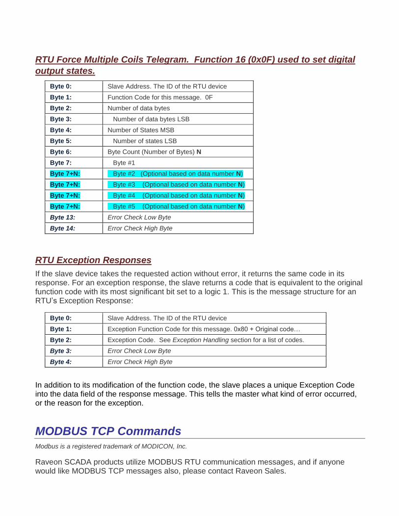
RTU Force Multiple Coils Telegram. Function 16 (0x0F) used to set digital
output states.
Byte 0: Slave Address. The ID of the RTU device
Byte 1: Function Code for this message. 0F
Byte 2: Number of data bytes
Byte 3: Number of data bytes LSB
Byte 4: Number of States MSB
Byte 5: Number of states LSB
Byte 6: Byte Count (Number of Bytes) N
Byte 7: Byte #1
Byte 7+N: Byte #2 (Optional based on data number N)
Byte 7+N: Byte #3 (Optional based on data number N)
Byte 7+N: Byte #4 (Optional based on data number N)
Byte 7+N: Byte #5 (Optional based on data number N)
Byte 13: Error Check Low Byte
Byte 14: Error Check High Byte
RTU Exception Responses
If the slave device takes the requested action without error, it returns the same code in its response. For an exception response, the slave returns a code that is equivalent to the original function code with its most significant bit set to a logic 1. This is the message structure for an RTU’s Exception Response:
Byte 0: Slave Address. The ID of the RTU device
Byte 1: Exception Function Code for this message. 0x80 + Original code…
Byte 2: Exception Code. See Exception Handling section for a list of codes.
Byte 3: Error Check Low Byte
Byte 4: Error Check High Byte
In addition to its modification of the function code, the slave places a unique Exception Code into the data field of the response message. This tells the master what kind of error occurred, or the reason for the exception.
MODBUS TCP Commands Modbus is a registered trademark of MODICON, Inc.
Raveon SCADA products utilize MODBUS RTU communication messages, and if anyone would like MODBUS TCP messages also, please contact Raveon Sales.
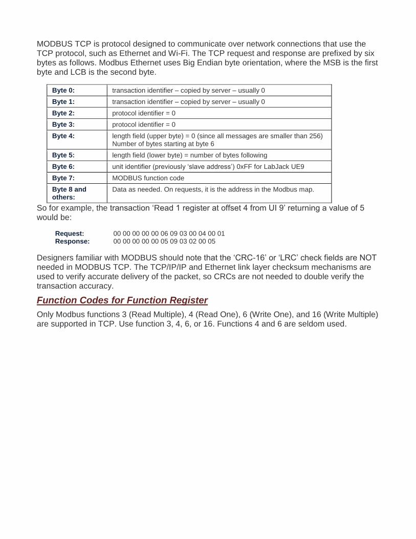
MODBUS TCP is protocol designed to communicate over network connections that use the TCP protocol, such as Ethernet and Wi-Fi. The TCP request and response are prefixed by six bytes as follows. Modbus Ethernet uses Big Endian byte orientation, where the MSB is the first byte and LCB is the second byte.
Byte 0: transaction identifier – copied by server – usually 0
Byte 1: transaction identifier – copied by server – usually 0
Byte 2: protocol identifier = 0
Byte 3: protocol identifier = 0
Byte 4: length field (upper byte) = 0 (since all messages are smaller than 256) Number of bytes starting at byte 6
Byte 5: length field (lower byte) = number of bytes following
Byte 6: unit identifier (previously ‘slave address’) 0xFF for LabJack UE9
Byte 7: MODBUS function code
Byte 8 and others:
Data as needed. On requests, it is the address in the Modbus map.
So for example, the transaction ‘Read 1 register at offset 4 from UI 9’ returning a value of 5 would be:
Request: 00 00 00 00 00 06 09 03 00 04 00 01 Response: 00 00 00 00 00 05 09 03 02 00 05
Designers familiar with MODBUS should note that the ‘CRC-16’ or ‘LRC’ check fields are NOT needed in MODBUS TCP. The TCP/IP/IP and Ethernet link layer checksum mechanisms are used to verify accurate delivery of the packet, so CRCs are not needed to double verify the transaction accuracy.
Function Codes for Function Register
Only Modbus functions 3 (Read Multiple), 4 (Read One), 6 (Write One), and 16 (Write Multiple) are supported in TCP. Use function 3, 4, 6, or 16. Functions 4 and 6 are seldom used.
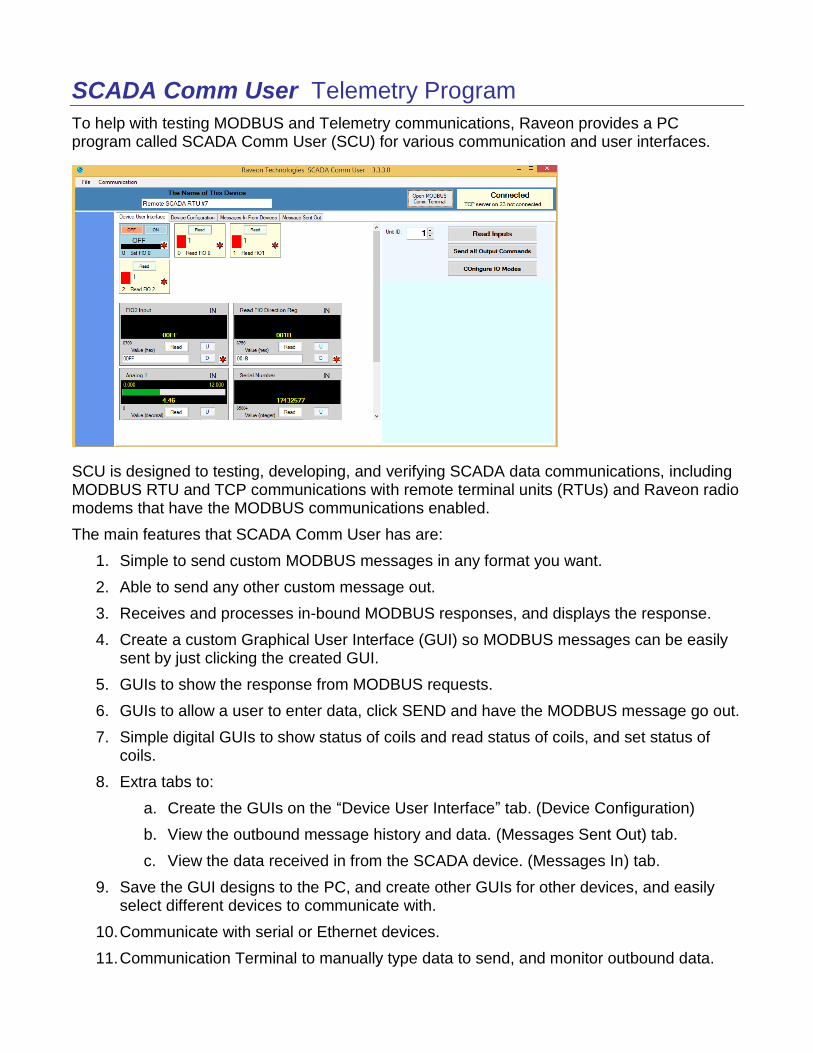
SCADA Comm User Telemetry Program
To help with testing MODBUS and Telemetry communications, Raveon provides a PC program called SCADA Comm User (SCU) for various communication and user interfaces.
SCU is designed to testing, developing, and verifying SCADA data communications, including MODBUS RTU and TCP communications with remote terminal units (RTUs) and Raveon radio modems that have the MODBUS communications enabled.
The main features that SCADA Comm User has are:
1. Simple to send custom MODBUS messages in any format you want.
2. Able to send any other custom message out.
3. Receives and processes in-bound MODBUS responses, and displays the response.
4. Create a custom Graphical User Interface (GUI) so MODBUS messages can be easily sent by just clicking the created GUI.
5. GUIs to show the response from MODBUS requests.
6. GUIs to allow a user to enter data, click SEND and have the MODBUS message go out.
7. Simple digital GUIs to show status of coils and read status of coils, and set status of coils.
8. Extra tabs to:
a. Create the GUIs on the “Device User Interface” tab. (Device Configuration)
b. View the outbound message history and data. (Messages Sent Out) tab.
c. View the data received in from the SCADA device. (Messages In) tab.
9. Save the GUI designs to the PC, and create other GUIs for other devices, and easily select different devices to communicate with.
10. Communicate with serial or Ethernet devices.
11. Communication Terminal to manually type data to send, and monitor outbound data.
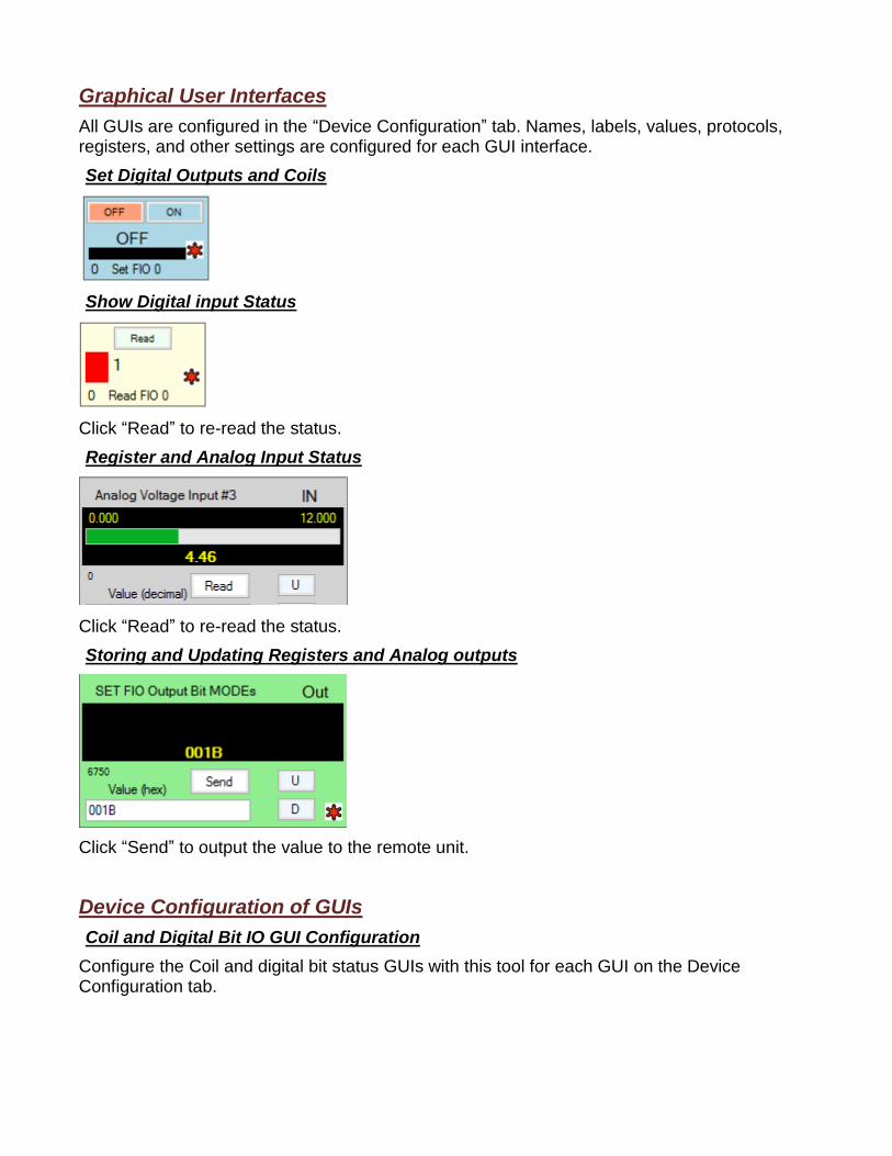
Graphical User Interfaces
All GUIs are configured in the “Device Configuration” tab. Names, labels, values, protocols, registers, and other settings are configured for each GUI interface.
Set Digital Outputs and Coils
Show Digital input Status
Click “Read” to re-read the status.
Register and Analog Input Status
Click “Read” to re-read the status.
Storing and Updating Registers and Analog outputs
Click “Send” to output the value to the remote unit.
Device Configuration of GUIs
Coil and Digital Bit IO GUI Configuration
Configure the Coil and digital bit status GUIs with this tool for each GUI on the Device Configuration tab.
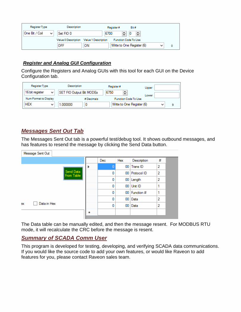
Register and Analog GUI Configuration
Configure the Registers and Analog GUIs with this tool for each GUI on the Device Configuration tab.
Messages Sent Out Tab
The Messages Sent Out tab is a powerful test/debug tool. It shows outbound messages, and has features to resend the message by clicking the Send Data button.
The Data table can be manually edited, and then the message resent. For MODBUS RTU mode, it will recalculate the CRC before the message is resent.
Summary of SCADA Comm User
This program is developed for testing, developing, and verifying SCADA data communications. If you would like the source code to add your own features, or would like Raveon to add features for you, please contact Raveon sales team.

Copyright, Notices, and Trademarks
Modbus is a registered trademark of MODICON, Inc.
Daisy Radio is a registered trademark of Raveon Technologies.
Raveon Technologies Corporation
2320 Cousteau Court
Vista, CA 92081
760-444-5995