
SC932C 9-Pin to RS-232-DCE Interface · 2021. 3. 31. · 7 DCE Device Cable Shield 25-Pin D Pin No....
14
INSTRUCTION MANUAL SC932C 9-Pin to RS-232-DCE Interface Revision: 6/97 Copyright (c) 1997 Campbell Scientific, Inc.
Transcript of SC932C 9-Pin to RS-232-DCE Interface · 2021. 3. 31. · 7 DCE Device Cable Shield 25-Pin D Pin No....

INST
RU
CT
ION
MA
NU
AL
SC932C 9-Pin toRS-232-DCE Interface
Revision: 6/97
C o p y r i g h t ( c ) 1 9 9 7C a m p b e l l S c i e n t i f i c , I n c .

Warranty and AssistanceThe SC932C 9-PIN TO RS232-DCE INTERFACE is warranted byCAMPBELL SCIENTIFIC, INC. to be free from defects in materials andworkmanship under normal use and service for twelve (12) months from date ofshipment unless specified otherwise. Batteries have no warranty. CAMPBELLSCIENTIFIC, INC.'s obligation under this warranty is limited to repairing orreplacing (at CAMPBELL SCIENTIFIC, INC.'s option) defective products.The customer shall assume all costs of removing, reinstalling, and shippingdefective products to CAMPBELL SCIENTIFIC, INC. CAMPBELLSCIENTIFIC, INC. will return such products by surface carrier prepaid. Thiswarranty shall not apply to any CAMPBELL SCIENTIFIC, INC. productswhich have been subjected to modification, misuse, neglect, accidents ofnature, or shipping damage. This warranty is in lieu of all other warranties,expressed or implied, including warranties of merchantability or fitness for aparticular purpose. CAMPBELL SCIENTIFIC, INC. is not liable for special,indirect, incidental, or consequential damages.
Products may not be returned without prior authorization. The followingcontact information is for US and International customers residing in countriesserved by Campbell Scientific, Inc. directly. Affiliate companies handle repairsfor customers within their territories. Please visit www.campbellsci.com todetermine which Campbell Scientific company serves your country. To obtaina Returned Materials Authorization (RMA), contact CAMPBELLSCIENTIFIC, INC., phone (435) 753-2342. After an applications engineerdetermines the nature of the problem, an RMA number will be issued. Pleasewrite this number clearly on the outside of the shipping container.CAMPBELL SCIENTIFIC's shipping address is:
CAMPBELL SCIENTIFIC, INC.RMA#_____815 West 1800 NorthLogan, Utah 84321-1784
CAMPBELL SCIENTIFIC, INC. does not accept collect calls.

i
SC932C 9-Pin to RS232-DCE InterfaceTable of ContentsPDF viewers note: These page numbers refer to the printed version of this document. Usethe Adobe Acrobat® bookmarks tab for links to specific sections.
1. Installation...................................................................1
2. Use with Intelligent Telephone Modems ...................1
3. Other Applications......................................................1
Appendices
A. SC932C to RS232 Device Connection Details ...... A-1A.1 Cable for Connection to a 25-Pin DCE Interface.................................A-1A.2 Cable for Connection to a 9-Pin DCE Interface...................................A-1
B. Technical Details of Special Modes of Operation B-1B.1 Power Modes........................................................................................B-1B.2 Handshaking Lines ...............................................................................B-1B.3 ‘Printer Only’ Output ...........................................................................B-1B.4 Maximum Recall Interval.....................................................................B-2
C. Specifications......................................................... C-1
List of Figures1. SC932C Connected to RAD Short-Haul Modem........................................1A-1. Minimum Connections for SC932C to 25-pin DCE Interface ............A-1A-2. Minimum Connections for SC932C to 9-pin DCE Interface ..............A-1B-1. Connections for Using SC932C in ‘Printer’ Mode .............................B-2
List of TablesC-1. 25-Pin Male Connector Pin-out ..........................................................C-2C-2. 9-Pin Male Connector Pin-out ............................................................C-2

This is a blank page.
1
SC932C 9-PIN TO RS232-DCE INTERFACE
The SC932C is used to interface a Campbell Scientific datalogger to modem devices that are configuredwith an RS232 DCE (Data Communications Equipment) serial port. The most common application is toallow the connection of a RAD short haul modem or third party telephone modem to a datalogger.
The SC932C has the following features:
• Generates true RS232 signal levels to the DCE device, resulting in good noise immunity.
• Powered from the 5V supply of the datalogger, which is also available to provide power to the DCE,if required for line-powered modems.
• Generates the required ring signal to wake up the datalogger, either when characters are receivedor when there is a ring signal from the DCE.
• Allows simultaneous connection of synchronous devices (e.g., Storage Modules) to the datalogger.
• Provides a mechanism for the datalogger to control the line state of intelligent modems via DTRhandshaking control.
• Convenient ‘jumperless’ design.
1. INSTALLATIONUse the SC12 ribbon cable (provided) toconnect the datalogger’s 9-pin CS I/O port tothe 9-pin connector on the SC932C. TheSC932C can usually be connected to theRS232 device by plugging the SC932C directlyinto the serial connector on the RS232 device.No further configuration is normally required.
A typical application with a RAD modem wouldcomprise:
SC932C
FIGURE 1. SC932C Connected to RADShort-Haul Modem
If the RS232 device does not have a suitable25-pin ‘D’ socket, you may need an adaptorcable (see Appendix A).
2. USE WITH INTELLIGENTTELEPHONE MODEMSIf an ‘intelligent’ telephone modem is beingused, configure it to allow the SC932C tocontrol its line status via the DTR line. This can
prevent the modem staying on-lineunnecessarily, which can lead to excessivetelephone charges and also delay reconnectionto the datalogger.
Most phone modems can be configured torespond to the DTR line, although this is notalways the default setting. Although this featureis sometimes controlled by a hardwareconfiguration switch, more often it is a softwaresetting, e.g. AT&D2&W is the command for aHayes-compatible modem to force the modemto follow the DTR status.
3. OTHER APPLICATIONSThe SC932C can be used in more specializedapplications. Appendix B gives installationdetails where even lower power consumptionmay be possible, and also for applicationswhere higher power outputs for the RS232device are required.

This is a blank page.

A-1
APPENDIX A. SC932C TO RS232 DEVICE CONNECTION DETAILS
This Appendix gives details of the cables required for connection of an SC932C to DCE type RS232devices, if the SC932C cannot be directly plugged into the 25-pin DCE, RS232 socket.
A.1 CABLE FOR CONNECTION TO A 25-PIN DCE INTERFACEA standard pin-to-pin cable is suitable. However, if a custom cable is to be made it must make thefollowing minimal connections:
2
3
SC932C 7
20
4*
1
2
3
7 DCE Device
20
4*
Cable Shield
25-Pin DPin No.
25-Pin DPin No.
FIGURE A-1. Minimum Connections for SC932C to 25-pin DCE Interface
NOTE: The link between pins 4 and 4 marked with the * may not be required — see the section onlow power operation in Appendix B.
A.2 CABLE FOR CONNECTION TO A 9-PIN DCE INTERFACESome newer modem-type devices are fitted with 9-pin D connectors designed to plug directly into 9-pinserial ports as found on most ‘AT’ style PCs. Commercial adaptor cables are available. If you use acustom made cable, it should have the following connections:
2
3
SC932C 7
20
4*
1
3
2
5 DCE Device
4
7*
Cable Shield
25-Pin DPin No.
9-Pin DPin No.
FIGURE A-2. Minimum Connections for SC932C to 9-pin DCE Interface
NOTE: The link between pins 4 and 7 marked with the * may not be required — see the section onlow power operation in Appendix B.

This is a blank page.
B-1
APPENDIX B. TECHNICAL DETAILS OF SPECIAL MODES OFOPERATION
The SC932C is designed as a simple plug-in device with no internal jumpers. This Appendix describesalternative modes of operation and also relates these to Campbell Scientific’s original SC932 interface,for those users who are already familiar with that interface.
B.1 POWER MODESB.1.1 NORMAL MODE
In the normal mode of operation for theSC932C, a continuous supply of 4.3V isavailable from the RTS line; this can be used asa source of power by some interfaces, e.g. theRAD modem. The RTS and DTR lines bothswitch to >7V when the SC932C becomesactive. This mode will work for the majority ofapplications. This mode is similar to themedium power setting of the SC932.
B.1.2 HIGH POWER MODE
A ‘high power’ setting can be forced, whereRTS and DTR are held permanently at >7V, byconnecting pin 11 of the 25-pin D connector to avoltage >3.5V DC. To do this, add a linkbetween pins 11 and 4 (RTS) on the SC932C’s25-pin D connector. In this mode the SC932Cconsumes approximately 10-15mAcontinuously. This mode is normally onlynecessary for devices which require fully activeinput lines to provide a source of power to allowthem to receive data and transmit it to theSC932C.
NOTE: In this mode the SC932C will notblock the transmission of synchronous data(e.g. Storage Module data) to the RS232device. This could cause a problem if, forexample, the RS232 device is reconfiguredby the stream of binary data. Synchronousdata is not normally transmitted through theSC932C when in its normal mode ofoperation.
B.1.3 LOW POWER MODE
The lowest power consumption can be achievedwith RS232 devices which do not need tosource power from the SC932C. This is doneby not connecting pin 11 or the RTS line to theRS232 device. This is because a small currentwill flow from the active RTS line into a standardRS232 RTS input on the device (normally
<1.5mA), even when the SC932C is inactive.Leaving RTS disconnected will only work if theRS232 device does not require an active RTSline during communication. Many high speedmodems do have this requirement, by default,but RTS/CTS handshaking can usually beturned off by software reconfiguration (pleaserefer to the modem manual).
B.2 HANDSHAKING LINESIn its normal power mode, and when inactive(i.e., the datalogger ME line is low) the SC932Conly holds the RTS line high to provide a sourceof power to line-powered modems, such as theRAD modem.
The DTR line is controlled by the ME line of thedatalogger. When ME is high the DTR line ispowered high (>7V), but when the ME linereturns to a low state, the DTR line enters ahigh impedance state; as far as the RS232device is concerned, this has the same effect asthe DTR line going low. This transition can beused to force the device to go off-line, if thedevice supports this.
This feature is useful for some telephonemodems as it allows the datalogger to force themodem off-line. The older SC932 only supportsthis type of handshaking when operated in itslow power mode.
NOTE: The SC932C can be modified tosupport a form of RTS handshaking for thesupport of some specialized half-duplexinterfaces. Please contact CampbellScientific for further details.
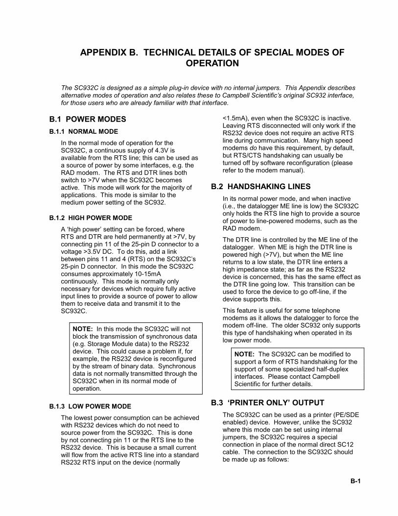
B.3 ‘PRINTER ONLY’ OUTPUTThe SC932C can be used as a printer (PE/SDEenabled) device. However, unlike the SC932where this mode can be set using internaljumpers, the SC932C requires a specialconnection in place of the normal direct SC12cable. The connection to the SC932C shouldbe made up as follows:
APPENDIX B. TECHNICAL DETAILS OF SPECIAL MODES OF OPERATION
B-2
1
2
4
5
6
9
1
2
5
9
DataloggerPin No.
SC932C9-Pin DPin No.
No connection to SC932C
No connection to SC932C
FIGURE B-1. Connections for Using SC932C in ‘Printer’ Mode
(Other wires can be left connected ordisconnected.)
With this connection the SC932C can beconnected in parallel to another CampbellScientific modem-type device. However, aswith the SC932, any data output to synchronousdevices (e.g., a Storage Module) will also betransmitted out through the RS232 connection.
B.4 MAXIMUM RECALL INTERVALFrom the time that the datalogger leavescommunications mode (ME goes low), there isa delay of approximately one second beforeserial or ring line activity from the RS232 devicewill re-awaken the datalogger. This preventsspurious messages from the RS232 device(such as ‘loss of carrier’ messages from amodem) waking up the datalogger. The onlyconsequence of this delay is that specializedsoftware which polls dataloggers at frequentintervals will not be able to wake the samedatalogger again during the delay period.
Campbell Scientific are aware of some modemswhich will re-trigger the ring line, despite thisdelay. The only consequence of this is that thedatalogger will remain in communications modefor an extra 30 seconds after the end of the call;this will waste a small amount of power anddelay any output to a Storage Module.

C-1
APPENDIX C. SPECIFICATIONS
Data rates: up to 38,400 baud (limited bydatalogger)
Size: 63 x 55 x 17mm (L x W x D), excludingmating D connectors
Operating environment: -25°C to +50°C, 0-95% RH (non-condensing)
Connector pin assignments: see Tables C-1and C-2
Power requirements: sources power fromdatalogger 5V supply via 9-pin interface.
TYPICAL CURRENT CONSUMPTION• <100 µA with no RS232 load and pin 11 not
connected
• 2.2 mA with RAD and no communication
• 9.3 mA with RAD, datalogger incommunications mode, but lowcommunications activity
• 10.2 mA with RAD, high communicationsactivity
Current consumption when driving other RS232modems will vary with the number of linesconnected and the input impedance of theinputs. With 3 inputs connected (DTR, RTSand Tx from the SC932C), of the minimum 3kΩinput impedance, and high communicationsactivity the consumption may be up to 16mA.
RS232 OUTPUT LEVELS• RTS 4.2 - 4.5V with 3kΩ load – quiescent
state (ME low)
• RTS full power 7 - 9V with 3kΩ load (MEhigh)
• DTR 7.5 - 9.5V with 3kΩ load (8.8V typicalwith RAD); short circuit current 30mAtypical
• Tx greater than ±5V with 3kΩ load
RS232 INPUT THRESHOLDS RX AND RI• Input low 0.8V minimum
• Input high 2.4V maximum
• Input resistance 5KΩ
PIN 11, POWER CONTROL INPUTTHRESHOLDS• Input low 1.3V maximum (normal power
mode)
• Input high 3.5V maximum (to enable highpower mode)
• Input resistance greater than 10kΩ
• Maximum input voltage 20V
TIME-OUTS• Minimum RING IN pulse width to generate
a ring signal to the datalogger is 20µs
• Minimum delay between ME going low andRING IN enable is 0.5s (1s typical)
EMC SPECIFICATION• Emissions BSEN 55022-1: 1995
• Immunity BSEN 50082-1: 1992

APPENDIX C. SPECIFICATIONS
C-2
CONNECTION DETAILS
TABLE C-1. 25-Pin Male Connector Pin-out
PinNo. I/O Name Description
1 GND Chassis Ground2 out TXD SC932C transmits data on
this line3 in RXD SC932C receives data on
this line4 out RTS Held active by SC932C7 GND Signal Ground11 in PWR If held >3.5V will force
SC932C into highpower mode
20 out DTR Held high if ME is high (seeAppendix B)
TABLE C-2. 9-Pin Male Connector Pin-out
PinNo. I/O Name Description
1 in +5V Regulated 5V supply2 GND Ground3 out RING Ring signal to datalogger4 out RXD SC932C transmits on this
line5 in ME Modem Enable6 in SDE Synchronous Device
Enable/Print Enable9 in TXD SC932C receives on this
line

This is a blank page.

Campbell Scientific Companies
Campbell Scientific, Inc. (CSI)815 West 1800 NorthLogan, Utah 84321UNITED STATES
Campbell Scientific Africa Pty. Ltd. (CSAf)PO Box 2450
Somerset West 7129SOUTH AFRICA
Campbell Scientific Australia Pty. Ltd. (CSA)PO Box 444
Thuringowa CentralQLD 4812 [email protected]
Campbell Scientific do Brazil Ltda. (CSB)Rua Luisa Crapsi Orsi, 15 Butantã
CEP: 005543-000 São Paulo SP BRAZILwww.campbellsci.com.br
Campbell Scientific Canada Corp. (CSC)11564 - 149th Street NW
Edmonton, Alberta T5M 1W7CANADA
Campbell Scientific Ltd. (CSL)Campbell Park
80 Hathern RoadShepshed, Loughborough LE12 9GX
UNITED [email protected]
Campbell Scientific Ltd. (France)Miniparc du Verger - Bat. H
1, rue de Terre Neuve - Les Ulis91967 COURTABOEUF CEDEX
FRANCEwww.campbellsci.fr
Campbell Scientific Spain, S. L.Psg. Font 14, local 8
08013 BarcelonaSPAIN
Please visit www.campbellsci.com to obtain contact information for your local US or International representative.


