SBC-RZN1D - Hardware Manual
15
SBC-RZN1D - Hardware Manual Hardware Manual 7 / 09.06.2020 emtrion GmbH
Transcript of SBC-RZN1D - Hardware Manual

SBC-RZN1D - Hardware Manual
Hardware Manual 7 / 09.06.2020
emtrion GmbH

SBC-RZN1D - Hardware Manual (Rev7) 2/15
© Copyright 2020 emtrion GmbH
All rights reserved. This documentation may not be photocopied or recorded on any electronic
media without written approval. The information contained in this documentation is subject to
change without prior notice. We assume no liability for erroneous information or its consequences.
Trademarks used from other companies refer exclusively to the products of those companies.
Revision: 7 / 09.06.2020
Rev Date/Signature Changes
1 14.03.18/Bue First release 2 07.05.18/Bue In chapters 2 and 3.3 NOR Flash reduced to 16 MB
In chapter 3.5 details of Ethernet interfaces added 3 06.08.18/Bue Mechanical characteristics in chapters 5 and 6 corrected 4 01.10.18/Bue Added mating connectors for J4 and J6 in chapter 4.2 5 01.08.19/Wi, Bue Rebranding changes, COM-RZN1D → SBC-RZN1D,
picture of front page updated 6 30.01.20/Bue In chapters 4.1 and 4.2 names of RJ45 connectors corrected 7 09.06.20/Bue Pinout of connector J4 in chapter 4.2.4 corrected
SBC-RZN1D - Hardware Manual (Rev7) 3/15
Contents
1 Introduction ................................................................................................................................................................ 4
2 Block Diagram ............................................................................................................................................................ 5
3 Functional Description ........................................................................................................................................... 6
3.1 Processor ............................................................................................................................................................. 6
3.2 DDR3 SDRAM ..................................................................................................................................................... 6
3.3 NOR-Flash ........................................................................................................................................................... 6
3.4 eMMC ................................................................................................................................................................... 6
3.5 Ethernet Interfaces .......................................................................................................................................... 6
3.6 Serial Ports .......................................................................................................................................................... 7
3.7 CAN ....................................................................................................................................................................... 7
3.8 RTC ........................................................................................................................................................................ 7
3.9 TPM ....................................................................................................................................................................... 7
3.10 EEPROM ............................................................................................................................................................... 7
3.11 Status LED ........................................................................................................................................................... 8
3.12 USB interface ..................................................................................................................................................... 8
3.13 SPI interface ....................................................................................................................................................... 8
3.14 Power Supply .................................................................................................................................................... 8
4 Connectors .................................................................................................................................................................. 9
4.1 Connector Locations ....................................................................................................................................... 9
4.2 External Connectors ..................................................................................................................................... 10
4.2.1 J6: Power Supply.................................................................................................................................. 10
4.2.2 J8, J9: RJ45 Connector ....................................................................................................................... 10
4.2.3 J1, J2: RJ45 Connector ....................................................................................................................... 10
4.2.4 J4: Serial Ports ....................................................................................................................................... 11
4.3 Internal Connectors ..................................................................................................................................... 12
4.3.1 J3: SPI ....................................................................................................................................................... 12
4.3.2 J5: Console ............................................................................................................................................. 12
4.3.3 J10, JTAG................................................................................................................................................. 12
4.3.4 J11: USB Device .................................................................................................................................... 12
5 Technical Characteristics .................................................................................................................................... 13
5.1 Electrical Specifications .............................................................................................................................. 13
5.2 Environmental Specifications ................................................................................................................... 13
5.3 Mechanical Specifications ......................................................................................................................... 13
6 Dimensional Drawing of PCB ............................................................................................................................ 14
7 References ................................................................................................................................................................ 15

SBC-RZN1D - Hardware Manual (Rev7) 4/15
1 Introduction The SBC-RZN1D module is an industrial communication controller based on the RZ/N1D processor
from Renesas.
The following table lists the features and interfaces of the SBC-RZN1D communication module:
SBC-RZN1D
512 MByte DDR3-1000 RAM 16 MB QSPI NOR Flash
8 GB eMMC NAND Flash 2 x Gb Ethernet
2 x 100 Mb Ethernet 2 x CAN 2.0B interface
2 x RS485 interface 1 x RS232 interface with RTS/CTS
RTC, battery backed 24 VDC power supply
The module is available in commercial temperature range 0°C to 70°C and optionally in extended
temperature range -40°C to 85°C.

SBC-RZN1D - Hardware Manual (Rev7) 5/15
2 Block Diagram The following figure shows the block diagram of the SBC-RZN1D.
RZ/N1D2 x ARM® Cortex®-A7
500 MHzwith NEON and VFPv4
RZ/N1D2 x ARM® Cortex®-A7
500 MHzwith NEON and VFPv4
CacheL1 16/16 KB I/D
L2 256 kB
CacheL1 16/16 KB I/D
L2 256 kB
R-IN Engine ARM® Cortex®-M3
125 MHz
R-IN Engine ARM® Cortex®-M3
125 MHz
ClocksClocks DMACDMAC INTCINTC
2 MB RAM2 MB RAM
EtherCATSlave
EtherCATSlave
16 * 12bit ADC
16 * 12bit ADC
up to 170 * GPIO
up to 170 * GPIO
2 * USB2.02 * USB2.0
2 * I²C2 * I²C
Parallel Bus I/F
Parallel Bus I/F
6 * SPI6 * SPI
2 * GMAC2 * GMAC
8 * UART8 * UART
512 MBDDR3 SDRAM
512 MBDDR3 SDRAM
DDR2/3-SDRAMController
16 Bit, DDR3-1000
DDR2/3-SDRAMController
16 Bit, DDR3-1000
Boot ROMBoot ROM
Advanced 5 Port Ethernet Switch
Advanced 5 Port Ethernet Switch
8 GBeMMC
8 GBeMMC
2 * CAN2 * CAN
2 *SDIO/eMMC
2 *SDIO/eMMC
QSPIQSPI NAND Flash I/F
NAND Flash I/F
JTAG, CoreSight
JTAG, CoreSight
16 MBQSPI NOR Flash
16 MBQSPI NOR Flash
CAN, RS485, RS232Drivers
CAN, RS485, RS232Drivers
SercosIIISlave
SercosIIISlave
LCDController
LCDController
TimerTimer RTCRTC
SecuritySecurity
DC/DCDC/DCSupply Voltages1.15V, 1.5V, 3.3 V
Supply Voltages1.15V, 1.5V, 3.3 V
24 V
CON2x5JTAG
CON2x5JTAG
CON 1x4USB Device
CON 1x4USB Device
CON1x6SPI
CON1x6SPI
Gb ETH PHYKSZ9031RNX
Gb ETH PHYKSZ9031RNX
RGMII2
RGMII1 RJ45with magnetics
RJ45with magnetics
100M ETH PHYKSZ8041NL
100M ETH PHYKSZ8041NL
TPMAT97SC3205T
TPMAT97SC3205T
EEPROM24LC02
EEPROM24LC02
I2C1
CON1x6Console
CON1x6Console
CON 1x172 * CAN
2 * RS4851 * RS232
CON 1x172 * CAN
2 * RS4851 * RS232
CON 1x224 DC in
CON 1x224 DC in
CAN1,CAN2,UART2,UART3,UART4
RGMII5
100M ETH PHYKSZ8041NL
100M ETH PHYKSZ8041NL
RGMII4
Gb ETH PHYKSZ9031RNX
Gb ETH PHYKSZ9031RNX
RJ45with magnetics
RJ45with magnetics
RJ45with magnetics
RJ45with magnetics
RJ45with magnetics
RJ45with magnetics
SPI5
USB1
UART1
JTAG
SDIO2
Blockdiagram COM-RZN1D, v002en, 04.04.18
4 * LED4 * LEDGPIO
BatteryCR1632
BatteryCR1632

SBC-RZN1D - Hardware Manual (Rev7) 6/15
3 Functional Description
3.1 Processor The SBC-RZN1D module is based on the processor RZ/N1D from Renesas [1]. This is a
heterogeneous multi core processor which incorporates a Dual Cortex®-A7 CPU at 500 MHz and an
additional Cortex®-M3 CPU at 125 MHz.
The Cortex®-M3 CPU is part of a R-IN Engine for industrial Ethernet communication which
additionally includes an Advanced 5 Port Switch, an EtherCAT slave controller, a Sercos III slave
controller a HWRTOS GMAC and two GMACs.
Besides the Ethernet interfaces further interfaces are available like CAN 2.0B and UARTs that are
used at SBC-RZN1D.
Further details of the processor can be found in the RZ/N1D Reference Manual [1].
3.2 DDR3 SDRAM The module incorporates a 4-Gbit DDR3(L) SDRAM that which is clocked at 500 MHz ((DDR3-1000
mode).
3.3 NOR-Flash A 16 MByte QSPI NOR Flash is connected to the QSPI interface of the RZ/N1D processor. The
maximum clock rate of the interface is 66 MHz. The NOR flash is used as boot device.
3.4 eMMC To store the operating system and application data, normally an 8 GByte eMMC is used in the SBC-
RZN1D module. It is connected to the SDIO1 interface of the RZ/N1D using 8 data lines.
The storage capacity of the eMMC can be adapted to customer’s needs by soldering different chips.
Please contact emtrion GmbH if another eMMC capacity is required.
3.5 Ethernet Interfaces The RZ/N1D processor incorporates five Ethernet interfaces. Four of them are available for users,
two are realized as Gbit Ethernet interfaces and two as 100 Mbit Ethernet interfaces.
The 100M interfaces use PHYs KSZ8041NL which are both controlled by MDIO interface MDIO2. The
PHY addresses are 4 four RGMII4 and 5 for RGMII5. The PHY of RGMII4 is configured as address 4
and its traffic signal is connected to SWITCH_MII_LINK[4]. The PHY of RGMII5 is configured as
address 5 and its traffic signal is connected to SWITCH_MII_LINK[5].
Both interfaces are accessible by RJ45 jacks the front. By the switch they can be combined to realize
ring or line topologies which are demanded by industrial networks.

SBC-RZN1D - Hardware Manual (Rev7) 7/15
The two Gb interfaces RGMII1 and RGMII2 use PHYs KSZ9031RNX. The PHY at RGMII1 is controlled
by an MDIO interface which is comprised by two GPIO pins. GPIO154 is used as MDC and GPIO155
is used as MDIO. The PHY address is 5. The PHY at RGMII2 is controlled by MDIO interface MDIO1.
The PHY address is 6.
which are both controlled by MDIO interface MDIO2. The PHY addresses are 4 four RGMII4 and 5
for RGMII5. The PHY of RGMII4 is configured as address 4 and its traffic signal is connected to
SWITCH_MII_LINK[4]. The PHY of RGMII5 is configured as address 5 and its traffic signal is
connected to SWITCH_MII_LINK[5].
Both interfaces are accessible by RJ45 jacks from the bottom.
3.6 Serial Ports The RZ/N1D processor incorporates up to eight serial ports. Three of them are available for users.
The UART3 and UART4 are realized as RS485 interfaces and the UART2 is realized as RS232
interface. All interfaces can be accessed by the pin header J4 at the top of the enclosure.
Besides these interfaces the fourth interface UART1 is available as TTL signals at a pin header that
fits to a UART-USB-Cable from FTDI. This interface is used by U-Boot and Linux as console interface.
3.7 CAN The RZ/N1D processor incorporates two CAN controllers, which comply with the ISO11898-1
specification. The CAN protocol specification 2.0B, with standard and extended message frames, is
supported. The maximum baud rate is 1Mbps.
Both interfaces can be accessed by the pin header J4 at the top of the enclosure.
3.8 RTC To enable time keeping while the module is powered off the integrated RTC of the processor
RZ/N1D is buffered by a coin cell CR1632. The battery will keep the RTC running for more than 5
years.
3.9 TPM A TPM AT97SC3205T from Microchip is connected to interface I2C1. The 7-bit address is 0x29.
By driving GPIO93 low the TPM is set in reset.
3.10 EEPROM An EEPROM 24LC02B is connected to interface I2C1. The EEPROM can store up to 256 bytes
configuration data. The 7-bit address of the EEPROM is 0x50.

SBC-RZN1D - Hardware Manual (Rev7) 8/15
3.11 Status LED Four green status LEDs are available at the front.
The LEDs are driven as following:
LED Signal
1 GPIO88 2 GPIO89 3 GPIO90 (CAT_LEDRUN) 4 GPIO91 (CAT_LEDERR)
The LEDs are on while the GPIO is driven high.
3.12 USB interface The interface USB1 is available internally as USB Device for production purposes. It is not available
for customers.
3.13 SPI interface The interface SPI5 is available internally at a 6 pin header. It is provided for future use and normally
not available for customers.
3.14 Power Supply The power consumption of the module is max. 0.2 A at +24V, +/- 50%. The current consumption
depends on the software running.

SBC-RZN1D - Hardware Manual (Rev7) 9/15
4 Connectors
4.1 Connector Locations

SBC-RZN1D - Hardware Manual (Rev7) 10/15
4.2 External Connectors
4.2.1 J6: Power Supply
Type Phoenix Contact MSTBA 2,5/2-G Mating connector: Phoenix Contact: MSTB 2,5/ 2-ST, 1754449
4.2.2 J1, J2: RJ45 TCP/IP Connectors
Type 1G BASE-T
Pin Signal
1 DA+
2 DA-
3 DB+
4 DC+
5 DC-
6 DB-
7 DD+
8 DD-
4.2.3 J8, J9: RJ45 Fieldbus Connectors
Type 10/100 BASE-T
Pin Signal
1 DA+
2 DA-
3 DB+
4 n/c
5 n/c
6 DB-
7 n/c
8 n/c
Pin Signal
1 24 VDC
2 GND

SBC-RZN1D - Hardware Manual (Rev7) 11/15
4.2.4 J4: Serial Ports
Type Phoenix Contact MSTBA 2,5/17-G Mating connector: Phoenix Contact: MSTB 2,5/17-ST, 1754740
Pin Signal
1 RS232_RxD
2 RS232_TxD
3 RS232_CTS
4 RS232_RTS
5 GND
6 RS485-1_B
7 RS485-1_A
8 GND
9 RS485-2_B
10 RS485-2_A
11 GND
12 CAN-1_H
13 CAN-1_L
14 GND
15 CAN-2_H
16 CAN-2_L
17 GND

SBC-RZN1D - Hardware Manual (Rev7) 12/15
4.3 Internal Connectors
4.3.1 J3: SPI
Type Header 1x6, 2.54 mm
4.3.2 J5: Console
Type Header 1x6, 2.54 mm
4.3.3 J10, JTAG
Type Header 2x5, 1.27 mm
Pin Signal Signal Pin
1 3.3V TMS 2 3 GND TCK 4
5 GND TDO 6
7 n/c TDI 8
9 TRST# RESET# 10
4.3.4 J11: USB Device
Type Microlatch
Pin Signal
1 SPI5_SCK
2 SPI5_MOSI
3 SPI5_MISO
4 SPI5_SS#
5 3.3V
6 GND
Pin Signal
1 GND
2 n/c
3 n/c
4 UART1_RxD
5 UART1_TxD
6 PU 10k
Pin Signal
1 VBUS
2 DM1
3 DP1
4 GND

SBC-RZN1D - Hardware Manual(Rev7) 13/15
5 Technical Characteristics
5.1 Electrical Specifications
Supply voltage 24V, +/-50%
Current consumption up to 0.2 A
5.2 Environmental Specifications
Operating temperature
Standard:
Extended:
Storage temperature
0 ... +70°C
-40 ... +85°C
-40 ... +125°C
Relative humidity 0 ... 95 %, non-condensing
5.3 Mechanical Specifications
Weight approx. 80 g
Board Glasepoxi FR-4, UL-listed, 8 layers
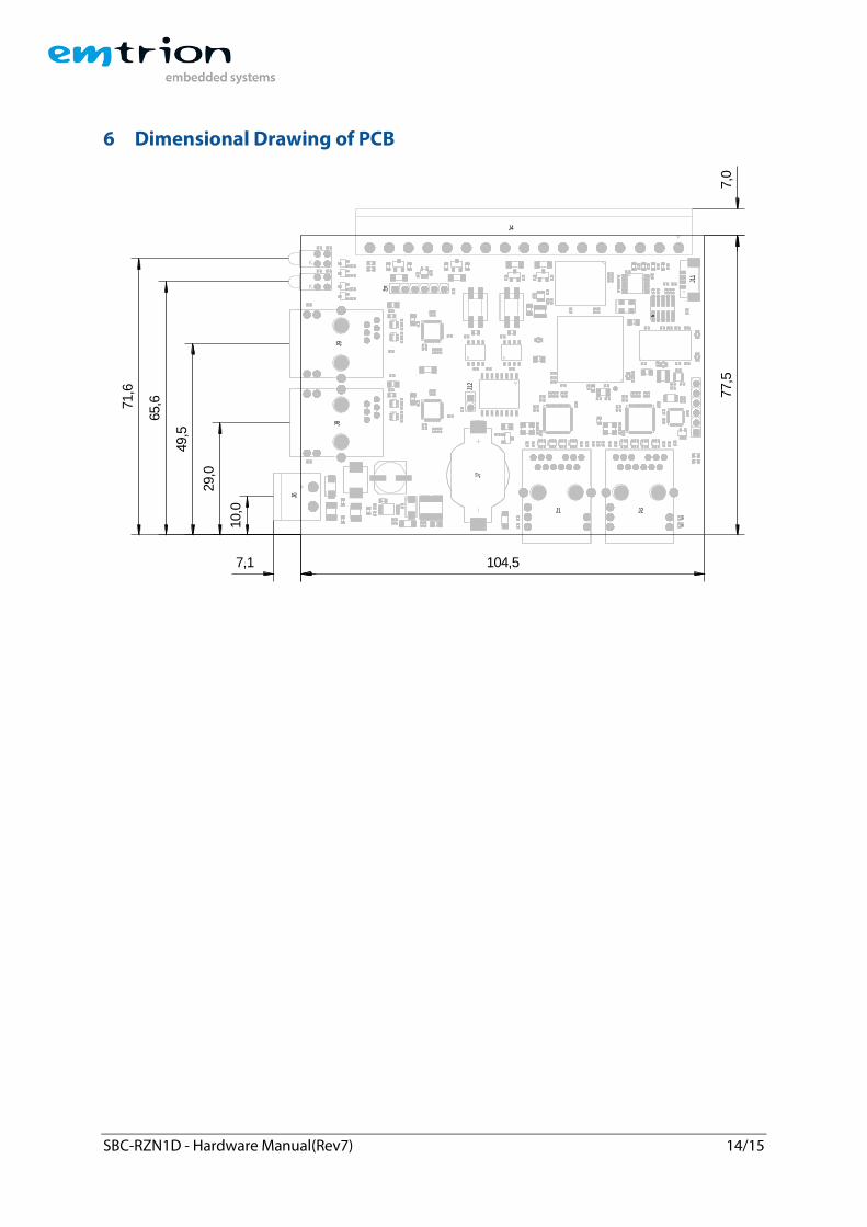
Dimensions 111.6 mm x 84.5 mm x 15.0 mm
SBC-RZN1D - Hardware Manual(Rev7) 14/15
6 Dimensional Drawing of PCB
49,5
7,1 104,5
77,5
7,0
10,0
29,0
65,671,6
J6
J8
J4
R93
J9
J1
R20
J2
J7
J5
J12
J11
SBC-RZN1D - Hardware Manual(Rev7) 15/15
7 References [1] Preliminary Datasheet RZ/N1D Group, RZ/N1S Group, RZ/N1L Group, R18DS0026EJ0050, Rev. 0.50, Mar. 08, 2017