SBC Configuration Examples for Mediant SBC -...
84
Configuration Note AudioCodes Mediant™ Series of Session Border Controllers (SBC) SBC Configuration Examples for Mediant SBC Version 7.2
Transcript of SBC Configuration Examples for Mediant SBC -...
Configuration Note
AudioCodes Mediant™ Series of Session Border Controllers (SBC)
SBC Configuration Examples for Mediant SBC
Version 7.2

Version 7.2 3 Mediant Gateway & SBC Series
Configuration Note Contents
Table of Contents 1 Introduction ......................................................................................................... 7
1.1 Configuration Terminology ...................................................................................... 7 1.2 Enabling the SBC Application ................................................................................. 8
2 Enterprise IP PBX with SIP Trunk and WAN Users .......................................... 9
2.1 Step 1: Assign Ethernet Ports to Ethernet Groups ................................................ 11 2.2 Step 2: Assign VLAN IDs to Ethernet Groups ....................................................... 12 2.3 Step 3: Add Logical IP Network Interfaces for LAN and WAN ............................... 12 2.4 Step 4: Add Media Realms for LAN and WAN ...................................................... 14 2.5 Step 5: Add SIP Interfaces for LAN and WAN ...................................................... 15 2.6 Step 6: Add Proxy Sets for IP PBX and SIP Trunk ............................................... 16 2.7 Step 7: Add IP Groups for IP PBX, SIP Trunk, and WAN Nomadic Users ............ 17 2.8 Step 8: Add Classification for WAN Nomadic Users ............................................. 18 2.9 Step 9: Add IP-to-IP Call Routing Rules ............................................................... 19
3 Alternative Routing upon SIP Trunk Failure ................................................... 21
3.1 SIP Trunk Redundancy ........................................................................................ 21 3.1.1 Step 1: Enable Keep-Alive for Proxy Set of Main SIP Trunk ...................................22 3.1.2 Step 2: Add a Proxy Set for Redundant SIP Trunk .................................................22 3.1.3 Step 3: Add an IP Group for Redundant SIP Trunk ................................................23 3.1.4 Step 4: Add Alternative IP-to-IP Call Routing Rules ................................................23
3.2 PSTN Fallback ..................................................................................................... 25 3.2.1 PSTN Fallback – Optimized Configuration ..............................................................26
3.2.1.1 Step 1: Enable Keep-Alive for SIP Trunk .................................................26 3.2.1.2 Step 2: Add Alternative IP-to-IP Call Routing Rule for PSTN Fallback ....26 3.2.1.3 Step 3: Assign Trunk Group to E1 Trunk .................................................27 3.2.1.4 Step 4: Add an IP-to-Trunk Group Routing Rule .....................................28 3.2.1.5 Step 5: Add a Tel-to-IP Routing Rule .......................................................28
3.2.2 PSTN Fallback through the Gateway Application ...................................................29 3.2.2.1 Step 1: Enable Keep-Alive for SIP Trunk .................................................29 3.2.2.2 Step 2: Add a SIP Interface for PSTN Gateway ......................................30 3.2.2.3 Step 3: Add a Proxy Set for PSTN Gateway ............................................31 3.2.2.4 Step 4: Add an IP Group for PSTN Gateway ...........................................31 3.2.2.5 Step 5: Add IP-to-IP Call Routing Rules for PSTN Fallback ....................32 3.2.2.6 Step 6: Assign a Trunk Group to the E1 Trunk ........................................33 3.2.2.7 Step 7: Add an IP-to-Trunk Group Routing Rule .....................................34 3.2.2.8 Step 8: Add a Tel-to-IP Routing Rule .......................................................34
4 Hosted WAN IP PBX .......................................................................................... 35
4.1 Step 1: Add Logical IP Network Interfaces for LAN and WAN ............................... 37 4.2 Step 2: Add Media Realms for LAN and WAN ...................................................... 37 4.3 Step 3: Add SIP Interfaces for LAN and WAN ...................................................... 38 4.4 Step 4: Configure a NAT Translation Rule ............................................................ 39 4.5 Step 5: Add a Proxy Set for Hosted IP PBX .......................................................... 40 4.6 Step 6: Add IP Groups for LAN Users and Hosted IP PBX ................................... 41 4.7 Step 7: Add a Classification Rule for LAN Users .................................................. 42 4.8 Step 8: Add IP-to-IP Call Routing Rules ............................................................... 43
Configuration Note 4 Document #: LTRT-31626
SBC Configuration Examples
5 Call Survivability for LAN Users upon Hosted IP PBX Failure ...................... 45
5.1 Step 1: Enable Keep-Alive for Hosted IP PBX ...................................................... 45 5.2 Step 2: Add an Alternative IP-to-IP Call Routing Rule ........................................... 46
6 SIP Normalization between SIP Entity Servers ............................................... 47
6.1 Step 1: Add a Logical IP Network Interface for LAN .............................................. 49 6.2 Step 2: Add a SIP Interface for LAN ..................................................................... 49 6.3 Step 3: Add Proxy Sets for SIP Servers ................................................................ 50 6.4 Step 4: Add IP Groups for SIP Servers ................................................................. 51 6.5 Step 5: Add IP-to-IP Call Routing Rules ............................................................... 52 6.6 Voice Transcoding ................................................................................................ 53
6.6.1 Step 1: Add Extension Coder Groups for SIP Entities ............................................53 6.6.2 Step 2: Add Allowed Coders Group for SIP Entity Server #1 ..................................54 6.6.3 Step 3: Add IP Profiles for SIP Entities and Assign their Coder Groups .................55 6.6.4 Step 4: Assign IP Profiles to SIP Entity IP Groups ..................................................56
6.7 Phone Number Manipulation ................................................................................ 57 6.7.1 Step 1: Add Number Manipulation Rules ................................................................57
6.8 SIP Message Manipulation ................................................................................... 60 6.8.1 Step 1: Add a SIP Message Manipulation Rule ......................................................60 6.8.2 Step 2: Assign Manipulation Rule to IP Group of SIP Entity Server #2 ..................61
7 Multi-Tenant Deployment ................................................................................. 63
7.1 Step 1: Add Logical IP Network Interfaces for LAN and WAN ............................... 67 7.2 Step 2: Add SBC Routing Policies ........................................................................ 68 7.3 Step 3: Add SRDs ................................................................................................ 68 7.4 Step 4: Add Media Realms ................................................................................... 69 7.5 Step 5: Add SIP Interfaces ................................................................................... 71 7.6 Step 6: Add Proxy Sets ........................................................................................ 72 7.7 Step 7: Add IP Groups .......................................................................................... 74 7.8 Step 8: Add Classification Rules ........................................................................... 76 7.9 Step 9: Add IP-to-IP Call Routing Rules ............................................................... 78
Version 7.2 5 Mediant Gateway & SBC Series
Configuration Note Notices
Notice This document provides configuration examples for the SBC application of AudioCodes' Mediant Session Border Controllers (SBC). Information contained in this document is believed to be accurate and reliable at the time of printing. However, due to ongoing product improvements and revisions, AudioCodes cannot guarantee accuracy of printed material after the Date Published nor can it accept responsibility for errors or omissions. Before consulting this document, check the corresponding Release Notes regarding feature preconditions and/or specific support in this release. Updates to this document and other documents as well as software files can be downloaded by registered customers at http://www.audiocodes.com/downloads.
© Copyright 2016 AudioCodes Ltd. All rights reserved.
This document is subject to change without notice.
Date Published: June-27-2016
Trademarks AudioCodes, AC, HD VoIP, HD VoIP Sounds Better, IPmedia, Mediant, MediaPack, What’s Inside Matters, OSN, SmartTAP, VMAS, VoIPerfect, VoIPerfectHD, Your Gateway To VoIP, 3GX, VocaNOM and CloudBond 365 are trademarks or registered trademarks of AudioCodes Limited All other products or trademarks are property of their respective owners. Product specifications are subject to change without notice.
WEEE EU Directive Pursuant to the WEEE EU Directive, electronic and electrical waste must not be disposed of with unsorted waste. Please contact your local recycling authority for disposal of this product.
Customer Support Customer technical support and services are provided by AudioCodes or by an authorized AudioCodes Service Partner. For more information on how to buy technical support for AudioCodes products and for contact information, please visit our Web site at www.audiocodes.com/support.
Abbreviations and Terminology Each abbreviation, unless widely used, is spelled out in full when first used. Throughout this document, unless otherwise specified, the term SBC refers to AudioCodes Mediant SBC products.
Configuration Note 6 Document #: LTRT-31626
SBC Configuration Examples
Important Notes
Note: The scope of this document does not fully cover security aspects for deploying the device in your environment. Security measures should be done in accordance with your organization’s security policies. For basic security guidelines, you can refer to AudioCodes Recommended Security Guidelines document.
Note: This document describes typical SBC deployment examples. However, your SBC deployment may require additional configurations specific to your network topology. If you have any questions regarding required configuration, please contact your AudioCodes sales representative.
Document Revision Record
LTRT Description
31626 Initial document release for Version 7.2.
Documentation Feedback AudioCodes continually strives to produce high quality documentation. If you have any comments (suggestions or errors) regarding this document, please fill out the Documentation Feedback form on our Web site at http://www.audiocodes.com/downloads.
Version 7.2 7 Mediant Gateway & SBC Series
Configuration Note 1. Introduction
1 Introduction This document provides a variety of deployment examples and corresponding configuration for AudioCodes' Mediant™ Session Border Controller (SBC) product series, Software Version 7.0. Each example includes a description of the example scenario topology as well as step-by-step procedures on how to configure the SBC. The configuration described in this document is through the SBC's Web-based management tool. The following deployment examples are provided: Enterprise IP PBX with SIP Trunk and WAN Users on page 9 Alternative Routing upon SIP Trunk Failure on page 21 Hosted WAN IP PBX on page 35 Call Survivability for LAN Users upon Hosted IP PBX Failure on page 45 SIP Normalization between SIP Entity Servers on page 47 Multi-Tenant Deployment on page 62
Notes:
• Throughout this document, callout arrows are used in configuration-related figures to indicate the required parameter configuration. Parameters without callout arrows indicate that the default value is used and thus, the parameter can be ignored.
• When you have completed all the configuration steps of an example, you must reset the device with a burn-to-flash memory in order for your settings to take effect. If you don't, your settings will not be maintained if the device is subsequently powered off, reset without a burn-to-flash, or crashes for whatever reason.
• It is recommended to verify that your configuration is correct by checking Syslog messages for any invalid configuration.
• Unlike in previous software releases where configuration entities (e.g., SIP Interface, Proxy Sets, and IP Groups) were associated with each other using table row indices, Version 7.0 uses the string names of the configuration entities. Thus, it is recommended to configure each configuration entity with meaningful names for easy identification.
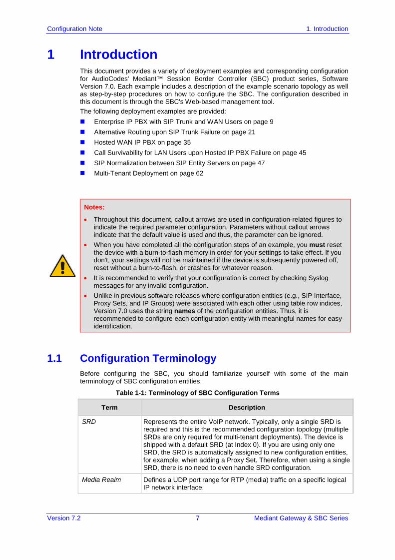
1.1 Configuration Terminology Before configuring the SBC, you should familiarize yourself with some of the main terminology of SBC configuration entities.
Table 1-1: Terminology of SBC Configuration Terms
Term Description
SRD Represents the entire VoIP network. Typically, only a single SRD is required and this is the recommended configuration topology (multiple SRDs are only required for multi-tenant deployments). The device is shipped with a default SRD (at Index 0). If you are using only one SRD, the SRD is automatically assigned to new configuration entities, for example, when adding a Proxy Set. Therefore, when using a single SRD, there is no need to even handle SRD configuration.
Media Realm Defines a UDP port range for RTP (media) traffic on a specific logical IP network interface.
Configuration Note 8 Document #: LTRT-31626
SBC Configuration Examples
Term Description
SIP Interface Represents a Layer-3 network, by defining a listening port for SIP signaling traffic on a specific logical IP network interface. Multiple SIP Interfaces can be associated with a single SRD, and therefore, if your VoIP deployment includes multiple Layer-3 networks (for example, SIP Trunk, LAN IP PBX, remote WAN users), a SIP Interface would be configured for each Layer-3 network and then all assigned to the same SRD.
IP Group Represents a SIP entity with which the SBC receives and sends calls. This can be a server (e.g., IP PBX or ITSP) or it can be a group of users (e.g., LAN IP phones). For servers, the IP Group is typically used to define the address of the entity by associating it with a Proxy Set. IP Groups are used in IP-to-IP routing rules to denote the source and destination of the call.
Proxy Set Defines the destination addresses (IP address or FQDN) of the SIP entity server (server-type IP Group). The Proxy Set is assigned to an IP Group belonging to the relevant SIP entity.
IP Profile Defines a set of call behavior (e.g., required coders, fax transport type, and transcoding method) that can be associated with a specific IP Group.
Classification Process that identifies the SIP entity (IP Group) from where the call is received.
SBC Routing Policy
SBC Routing Policy logically groups routing and manipulation (inbound and outbound) rules to create "separate" manipulation and routing tables. The SBC Routing Policy is assigned to an SRD. The SBC Routing Policy also enables Least Cost Routing (LCR) for routing rules and associates an LDAP server for LDAP-based routing. As multiple SBC Routing Policies are required only for multi-tenant deployments, for most deployments only a single SBC Routing Policy is required. When only a single SBC Routing Policy is required, handling of this configuration entity is not required as a default SBC Routing Policy is provided, which is automatically associated with all relevant configuration entities.
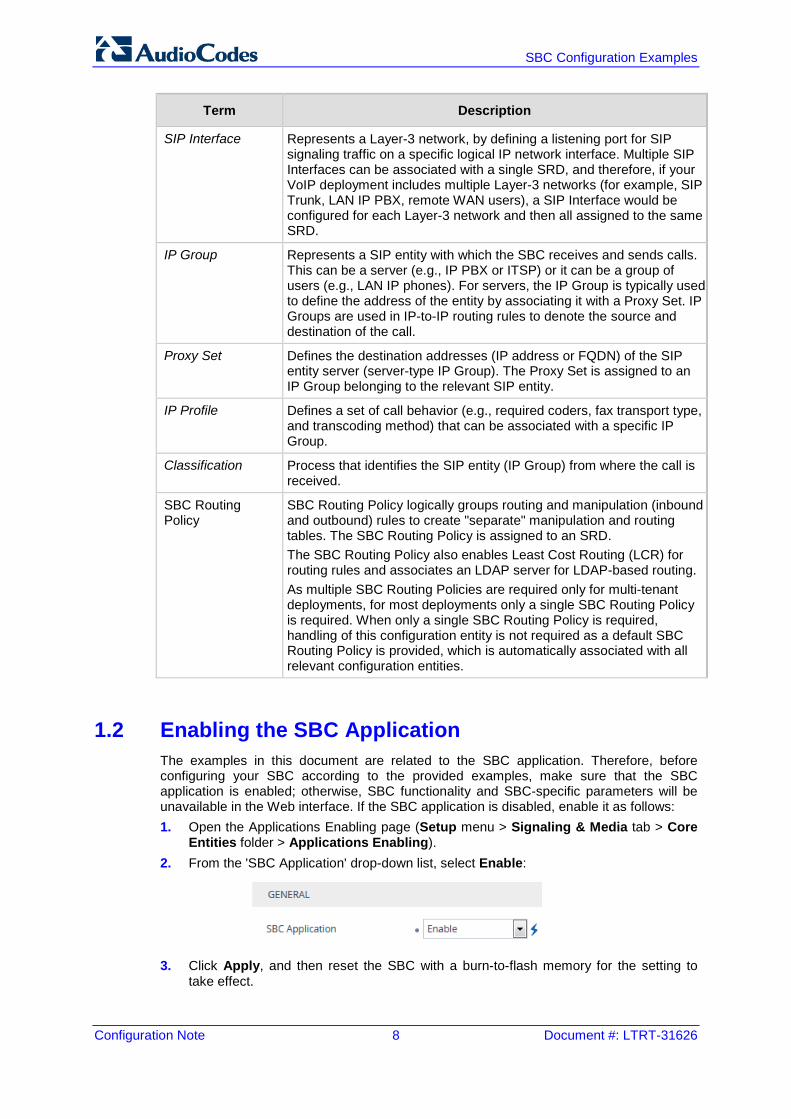
1.2 Enabling the SBC Application The examples in this document are related to the SBC application. Therefore, before configuring your SBC according to the provided examples, make sure that the SBC application is enabled; otherwise, SBC functionality and SBC-specific parameters will be unavailable in the Web interface. If the SBC application is disabled, enable it as follows: 1. Open the Applications Enabling page (Setup menu > Signaling & Media tab > Core
Entities folder > Applications Enabling). 2. From the 'SBC Application' drop-down list, select Enable:
3. Click Apply, and then reset the SBC with a burn-to-flash memory for the setting to
take effect.
Version 7.2 9 Mediant Gateway & SBC Series
Configuration Note 2. Enterprise IP PBX with SIP Trunk and WAN Users
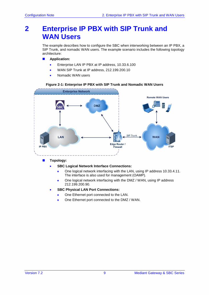
2 Enterprise IP PBX with SIP Trunk and WAN Users The example describes how to configure the SBC when interworking between an IP PBX, a SIP Trunk, and nomadic WAN users. The example scenario includes the following topology architecture: Application:
• Enterprise LAN IP PBX at IP address, 10.33.6.100 • WAN SIP Trunk at IP address, 212.199.200.10 • Nomadic WAN users
Figure 2-1: Enterprise IP PBX with SIP Trunk and Nomadic WAN Users
Topology:
• SBC Logical Network Interface Connections: ♦ One logical network interfacing with the LAN, using IP address 10.33.4.11.
The interface is also used for management (OAMP). ♦ One logical network interfacing with the DMZ / WAN, using IP address
212.199.200.90. • SBC Physical LAN Port Connections:
♦ One Ethernet port connected to the LAN. ♦ One Ethernet port connected to the DMZ / WAN.
Configuration Note 10 Document #: LTRT-31626
SBC Configuration Examples
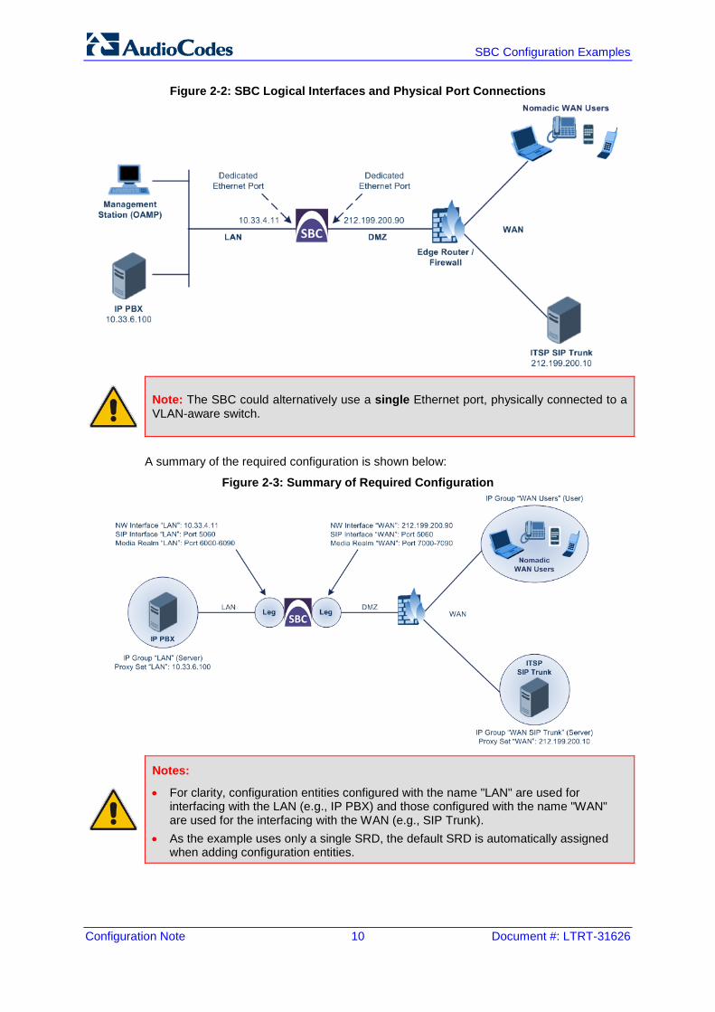
Figure 2-2: SBC Logical Interfaces and Physical Port Connections
Note: The SBC could alternatively use a single Ethernet port, physically connected to a VLAN-aware switch.
A summary of the required configuration is shown below:
Figure 2-3: Summary of Required Configuration
Notes:
• For clarity, configuration entities configured with the name "LAN" are used for interfacing with the LAN (e.g., IP PBX) and those configured with the name "WAN" are used for the interfacing with the WAN (e.g., SIP Trunk).
• As the example uses only a single SRD, the default SRD is automatically assigned when adding configuration entities.
Version 7.2 11 Mediant Gateway & SBC Series
Configuration Note 2. Enterprise IP PBX with SIP Trunk and WAN Users
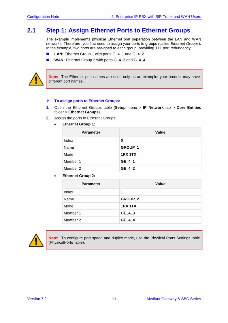
2.1 Step 1: Assign Ethernet Ports to Ethernet Groups The example implements physical Ethernet port separation between the LAN and WAN networks. Therefore, you first need to assign your ports to groups (called Ethernet Groups). In the example, two ports are assigned to each group, providing 1+1 port redundancy: LAN: Ethernet Group 1 with ports G_4_1 and G_4_2 WAN: Ethernet Group 2 with ports G_4_3 and G_4_4
Note: The Ethernet port names are used only as an example; your product may have different port names.
To assign ports to Ethernet Groups:
1. Open the Ethernet Groups table (Setup menu > IP Network tab > Core Entities folder > Ethernet Groups).
2. Assign the ports to Ethernet Groups: • Ethernet Group 1:
Parameter Value
Index 0
Name GROUP_1
Mode 1RX 1TX
Member 1 GE_4_1
Member 2 GE_4_2
• Ethernet Group 2:
Parameter Value
Index 1
Name GROUP_2
Mode 1RX 1TX
Member 1 GE_4_3
Member 2 GE_4_4
Note: To configure port speed and duplex mode, use the Physical Ports Settings table (PhysicalPortsTable).
Configuration Note 12 Document #: LTRT-31626
SBC Configuration Examples
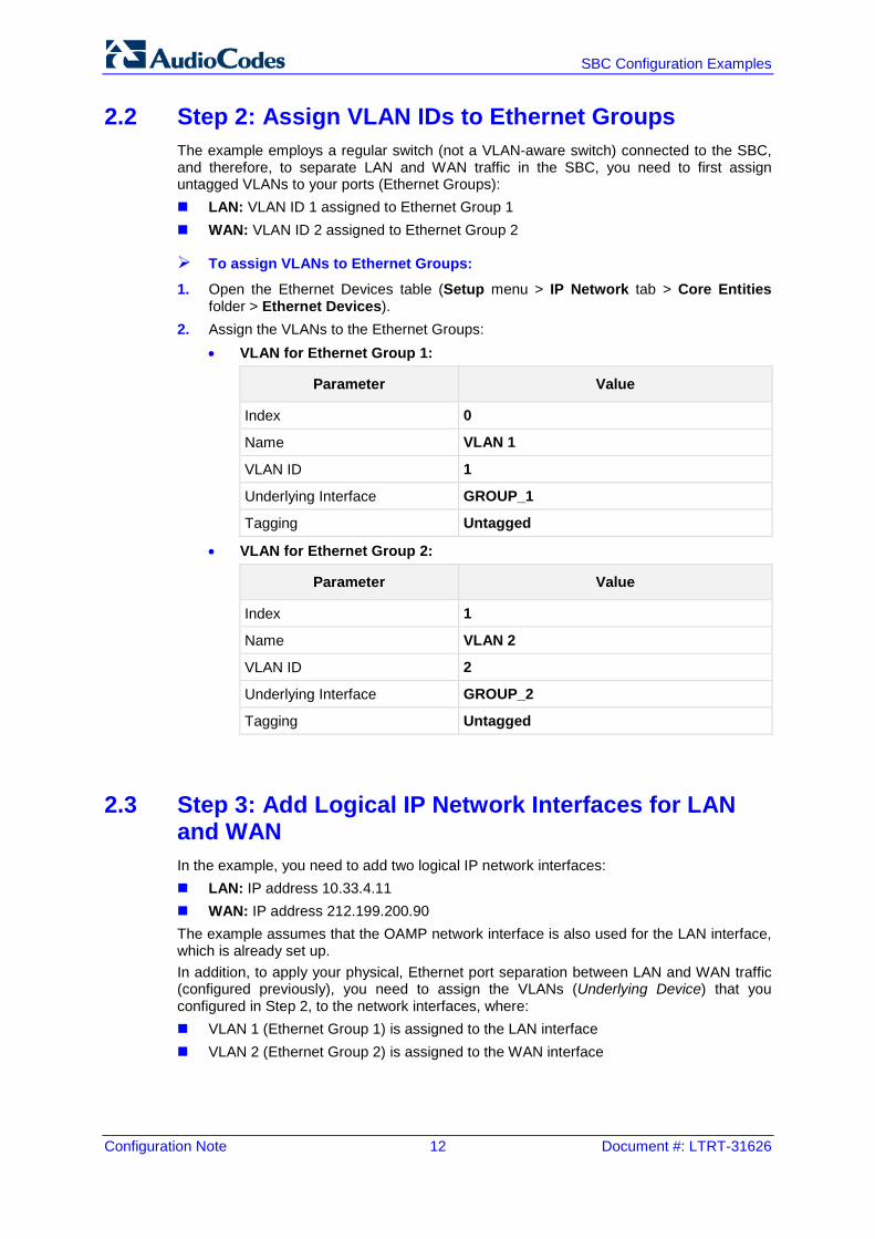
2.2 Step 2: Assign VLAN IDs to Ethernet Groups The example employs a regular switch (not a VLAN-aware switch) connected to the SBC, and therefore, to separate LAN and WAN traffic in the SBC, you need to first assign untagged VLANs to your ports (Ethernet Groups): LAN: VLAN ID 1 assigned to Ethernet Group 1 WAN: VLAN ID 2 assigned to Ethernet Group 2
To assign VLANs to Ethernet Groups:
1. Open the Ethernet Devices table (Setup menu > IP Network tab > Core Entities folder > Ethernet Devices).
2. Assign the VLANs to the Ethernet Groups: • VLAN for Ethernet Group 1:
Parameter Value
Index 0
Name VLAN 1
VLAN ID 1
Underlying Interface GROUP_1
Tagging Untagged
• VLAN for Ethernet Group 2:
Parameter Value
Index 1
Name VLAN 2
VLAN ID 2
Underlying Interface GROUP_2
Tagging Untagged
2.3 Step 3: Add Logical IP Network Interfaces for LAN and WAN In the example, you need to add two logical IP network interfaces: LAN: IP address 10.33.4.11 WAN: IP address 212.199.200.90 The example assumes that the OAMP network interface is also used for the LAN interface, which is already set up. In addition, to apply your physical, Ethernet port separation between LAN and WAN traffic (configured previously), you need to assign the VLANs (Underlying Device) that you configured in Step 2, to the network interfaces, where: VLAN 1 (Ethernet Group 1) is assigned to the LAN interface VLAN 2 (Ethernet Group 2) is assigned to the WAN interface
Version 7.2 13 Mediant Gateway & SBC Series
Configuration Note 2. Enterprise IP PBX with SIP Trunk and WAN Users
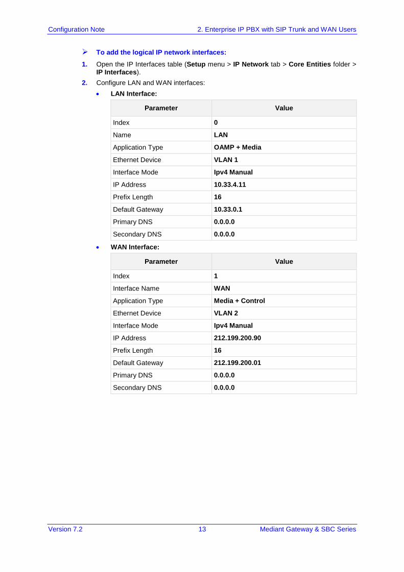
To add the logical IP network interfaces:
1. Open the IP Interfaces table (Setup menu > IP Network tab > Core Entities folder > IP Interfaces).
2. Configure LAN and WAN interfaces: • LAN Interface:
Parameter Value
Index 0
Name LAN
Application Type OAMP + Media
Ethernet Device VLAN 1
Interface Mode Ipv4 Manual
IP Address 10.33.4.11
Prefix Length 16
Default Gateway 10.33.0.1
Primary DNS 0.0.0.0
Secondary DNS 0.0.0.0
• WAN Interface:
Parameter Value
Index 1
Interface Name WAN
Application Type Media + Control
Ethernet Device VLAN 2
Interface Mode Ipv4 Manual
IP Address 212.199.200.90
Prefix Length 16
Default Gateway 212.199.200.01
Primary DNS 0.0.0.0
Secondary DNS 0.0.0.0
Configuration Note 14 Document #: LTRT-31626
SBC Configuration Examples
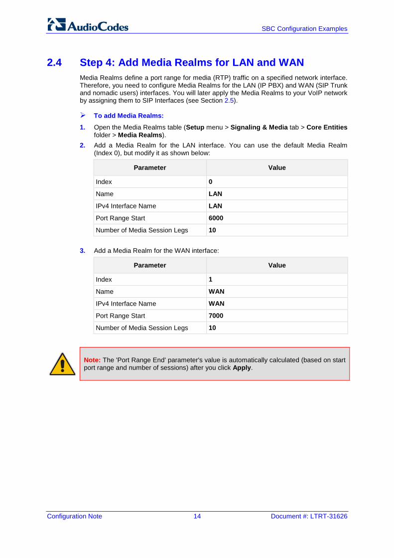
2.4 Step 4: Add Media Realms for LAN and WAN Media Realms define a port range for media (RTP) traffic on a specified network interface. Therefore, you need to configure Media Realms for the LAN (IP PBX) and WAN (SIP Trunk and nomadic users) interfaces. You will later apply the Media Realms to your VoIP network by assigning them to SIP Interfaces (see Section 2.5).
To add Media Realms:
1. Open the Media Realms table (Setup menu > Signaling & Media tab > Core Entities folder > Media Realms).
2. Add a Media Realm for the LAN interface. You can use the default Media Realm (Index 0), but modify it as shown below:
Parameter Value
Index 0
Name LAN
IPv4 Interface Name LAN
Port Range Start 6000
Number of Media Session Legs 10
3. Add a Media Realm for the WAN interface:
Parameter Value
Index 1
Name WAN
IPv4 Interface Name WAN
Port Range Start 7000
Number of Media Session Legs 10
Note: The 'Port Range End' parameter's value is automatically calculated (based on start port range and number of sessions) after you click Apply.

Version 7.2 15 Mediant Gateway & SBC Series
Configuration Note 2. Enterprise IP PBX with SIP Trunk and WAN Users
2.5 Step 5: Add SIP Interfaces for LAN and WAN The SIP Interface represents a Layer-3 network, defining the listening port for SIP signaling traffic on a specific network interface. The SIP Interface also determines the port and network interface for media (Media Realm, configured in Section 2.4). Therefore, you need to add a SIP Interface for the LAN and WAN interfaces.
To add SIP Interfaces:
1. Open the SIP Interfaces table (Setup menu > Signaling & Media tab > Core Entities folder > SIP Interfaces)
2. Add a SIP Interface for the LAN interface. You can use the default SIP Interface (Index 0), but modify it as shown below:
Parameter Value
Index 0
Name LAN
Network Interface LAN
Application Type SBC
UDP Port 5060
TCP Port 5060
TLS Port 5061
Media Realm LAN
3. Add a SIP Interface for the WAN interface:
Parameter Value
Index 1
Name WAN
Network Interface WAN
Application Type SBC
UDP Port 5060
TCP Port 5060
TLS Port 5061
Media Realm WAN
Configuration Note 16 Document #: LTRT-31626
SBC Configuration Examples
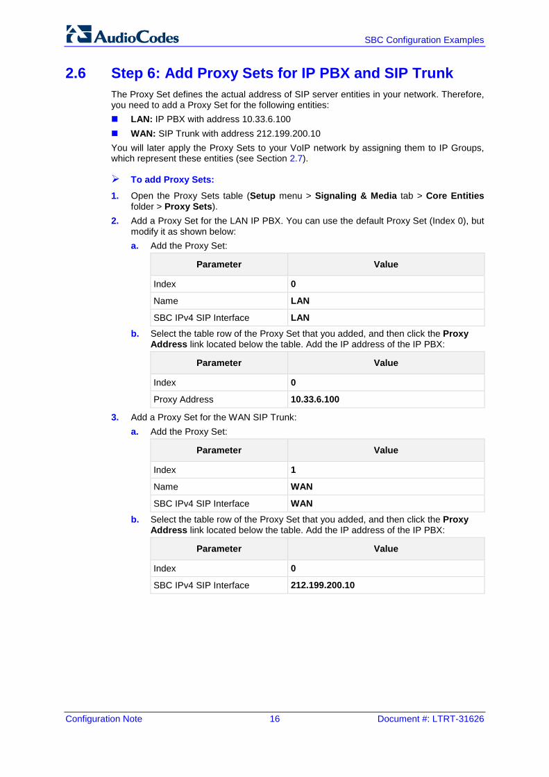
2.6 Step 6: Add Proxy Sets for IP PBX and SIP Trunk The Proxy Set defines the actual address of SIP server entities in your network. Therefore, you need to add a Proxy Set for the following entities: LAN: IP PBX with address 10.33.6.100 WAN: SIP Trunk with address 212.199.200.10 You will later apply the Proxy Sets to your VoIP network by assigning them to IP Groups, which represent these entities (see Section 2.7).
To add Proxy Sets:
1. Open the Proxy Sets table (Setup menu > Signaling & Media tab > Core Entities folder > Proxy Sets).
2. Add a Proxy Set for the LAN IP PBX. You can use the default Proxy Set (Index 0), but modify it as shown below: a. Add the Proxy Set:
Parameter Value
Index 0
Name LAN
SBC IPv4 SIP Interface LAN b. Select the table row of the Proxy Set that you added, and then click the Proxy
Address link located below the table. Add the IP address of the IP PBX:
Parameter Value
Index 0
Proxy Address 10.33.6.100
3. Add a Proxy Set for the WAN SIP Trunk: a. Add the Proxy Set:
Parameter Value
Index 1
Name WAN
SBC IPv4 SIP Interface WAN b. Select the table row of the Proxy Set that you added, and then click the Proxy
Address link located below the table. Add the IP address of the IP PBX:
Parameter Value
Index 0
SBC IPv4 SIP Interface 212.199.200.10
Version 7.2 17 Mediant Gateway & SBC Series
Configuration Note 2. Enterprise IP PBX with SIP Trunk and WAN Users
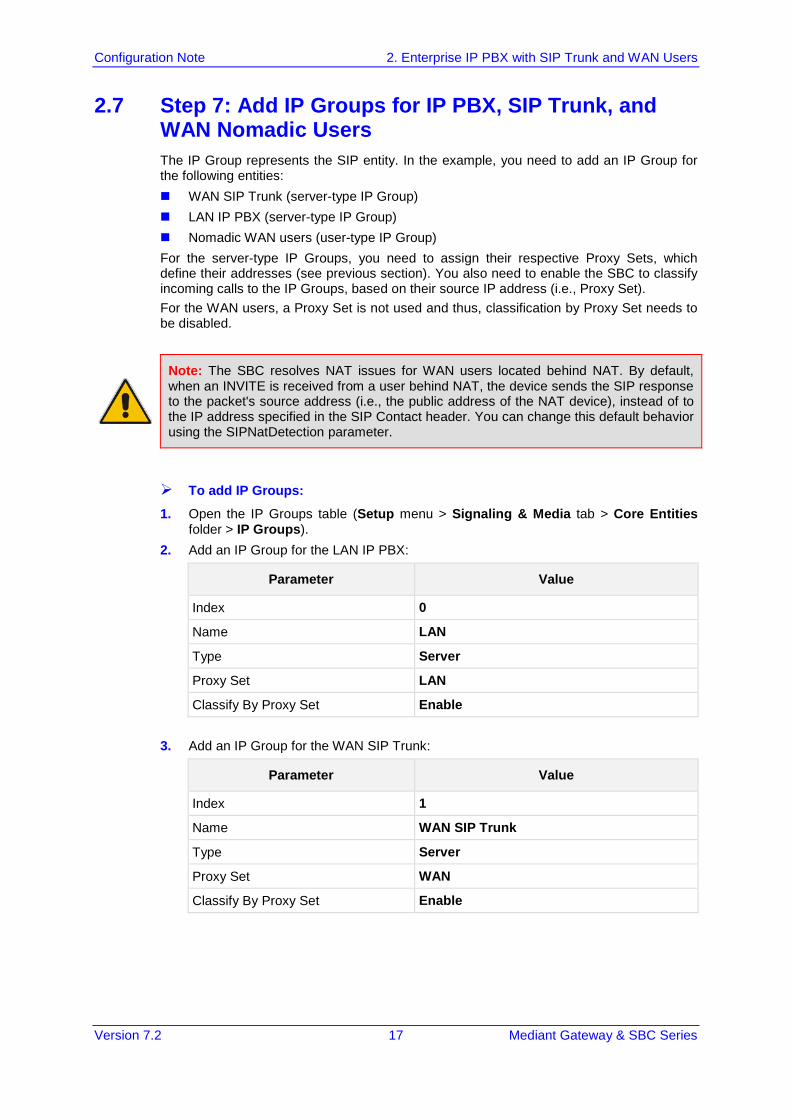
2.7 Step 7: Add IP Groups for IP PBX, SIP Trunk, and WAN Nomadic Users The IP Group represents the SIP entity. In the example, you need to add an IP Group for the following entities: WAN SIP Trunk (server-type IP Group) LAN IP PBX (server-type IP Group) Nomadic WAN users (user-type IP Group) For the server-type IP Groups, you need to assign their respective Proxy Sets, which define their addresses (see previous section). You also need to enable the SBC to classify incoming calls to the IP Groups, based on their source IP address (i.e., Proxy Set). For the WAN users, a Proxy Set is not used and thus, classification by Proxy Set needs to be disabled.
Note: The SBC resolves NAT issues for WAN users located behind NAT. By default, when an INVITE is received from a user behind NAT, the device sends the SIP response to the packet's source address (i.e., the public address of the NAT device), instead of to the IP address specified in the SIP Contact header. You can change this default behavior using the SIPNatDetection parameter.
To add IP Groups:
1. Open the IP Groups table (Setup menu > Signaling & Media tab > Core Entities folder > IP Groups).
2. Add an IP Group for the LAN IP PBX:
Parameter Value
Index 0
Name LAN
Type Server
Proxy Set LAN
Classify By Proxy Set Enable
3. Add an IP Group for the WAN SIP Trunk:
Parameter Value
Index 1
Name WAN SIP Trunk
Type Server
Proxy Set WAN
Classify By Proxy Set Enable
Configuration Note 18 Document #: LTRT-31626
SBC Configuration Examples
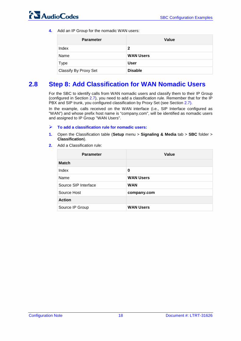
4. Add an IP Group for the nomadic WAN users:
Parameter Value
Index 2
Name WAN Users
Type User
Classify By Proxy Set Disable
2.8 Step 8: Add Classification for WAN Nomadic Users For the SBC to identify calls from WAN nomadic users and classify them to their IP Group (configured in Section 2.7), you need to add a classification rule. Remember that for the IP PBX and SIP trunk, you configured classification by Proxy Set (see Section 2.7). In the example, calls received on the WAN interface (i.e., SIP Interface configured as "WAN") and whose prefix host name is “company.com”, will be identified as nomadic users and assigned to IP Group "WAN Users".
To add a classification rule for nomadic users:
1. Open the Classification table (Setup menu > Signaling & Media tab > SBC folder > Classification).
2. Add a Classification rule:
Parameter Value
Match
Index 0
Name WAN Users
Source SIP Interface WAN
Source Host company.com
Action
Source IP Group WAN Users
Version 7.2 19 Mediant Gateway & SBC Series
Configuration Note 2. Enterprise IP PBX with SIP Trunk and WAN Users
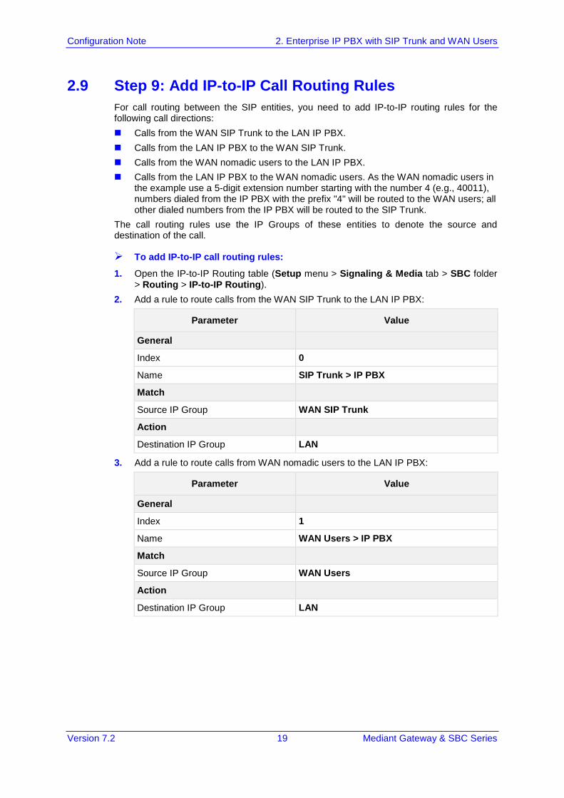
2.9 Step 9: Add IP-to-IP Call Routing Rules For call routing between the SIP entities, you need to add IP-to-IP routing rules for the following call directions: Calls from the WAN SIP Trunk to the LAN IP PBX. Calls from the LAN IP PBX to the WAN SIP Trunk. Calls from the WAN nomadic users to the LAN IP PBX. Calls from the LAN IP PBX to the WAN nomadic users. As the WAN nomadic users in
the example use a 5-digit extension number starting with the number 4 (e.g., 40011), numbers dialed from the IP PBX with the prefix "4" will be routed to the WAN users; all other dialed numbers from the IP PBX will be routed to the SIP Trunk.
The call routing rules use the IP Groups of these entities to denote the source and destination of the call.
To add IP-to-IP call routing rules:
1. Open the IP-to-IP Routing table (Setup menu > Signaling & Media tab > SBC folder > Routing > IP-to-IP Routing).
2. Add a rule to route calls from the WAN SIP Trunk to the LAN IP PBX:
Parameter Value
General
Index 0
Name SIP Trunk > IP PBX
Match
Source IP Group WAN SIP Trunk
Action
Destination IP Group LAN
3. Add a rule to route calls from WAN nomadic users to the LAN IP PBX:
Parameter Value
General
Index 1
Name WAN Users > IP PBX
Match
Source IP Group WAN Users
Action
Destination IP Group LAN
Configuration Note 20 Document #: LTRT-31626
SBC Configuration Examples
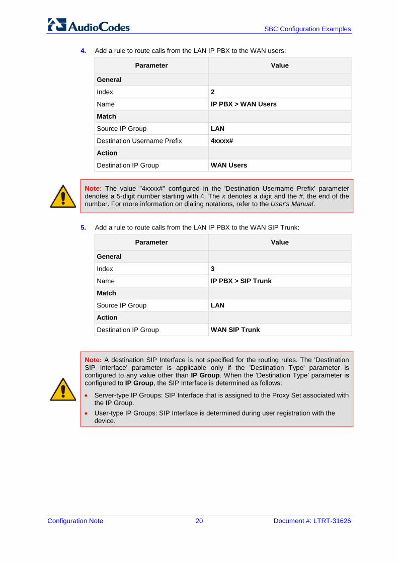
4. Add a rule to route calls from the LAN IP PBX to the WAN users:
Parameter Value
General
Index 2
Name IP PBX > WAN Users
Match
Source IP Group LAN
Destination Username Prefix 4xxxx#
Action
Destination IP Group WAN Users
Note: The value "4xxxx#" configured in the 'Destination Username Prefix' parameter denotes a 5-digit number starting with 4. The x denotes a digit and the #, the end of the number. For more information on dialing notations, refer to the User's Manual.
5. Add a rule to route calls from the LAN IP PBX to the WAN SIP Trunk:
Parameter Value
General
Index 3
Name IP PBX > SIP Trunk
Match
Source IP Group LAN
Action
Destination IP Group WAN SIP Trunk
Note: A destination SIP Interface is not specified for the routing rules. The 'Destination SIP Interface' parameter is applicable only if the 'Destination Type' parameter is configured to any value other than IP Group. When the 'Destination Type' parameter is configured to IP Group, the SIP Interface is determined as follows:
• Server-type IP Groups: SIP Interface that is assigned to the Proxy Set associated with the IP Group.
• User-type IP Groups: SIP Interface is determined during user registration with the device.
Version 7.2 21 Mediant Gateway & SBC Series
Configuration Note 3. Alternative Routing upon SIP Trunk Failure
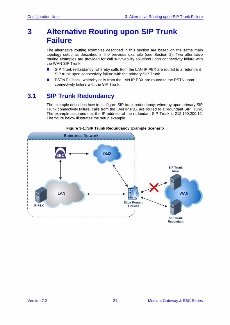
3 Alternative Routing upon SIP Trunk Failure The alternative routing examples described in this section are based on the same main topology setup as described in the previous example (see Section 2). Two alternative routing examples are provided for call survivability solutions upon connectivity failure with the WAN SIP Trunk: SIP Trunk redundancy, whereby calls from the LAN IP PBX are routed to a redundant
SIP trunk upon connectivity failure with the primary SIP Trunk. PSTN Fallback, whereby calls from the LAN IP PBX are routed to the PSTN upon
connectivity failure with the SIP Trunk.
3.1 SIP Trunk Redundancy The example describes how to configure SIP trunk redundancy, whereby upon primary SIP Trunk connectivity failure, calls from the LAN IP PBX are routed to a redundant SIP Trunk. The example assumes that the IP address of the redundant SIP Trunk is 212.199.200.12. The figure below illustrates the setup example.
Figure 3-1: SIP Trunk Redundancy Example Scenario
Configuration Note 22 Document #: LTRT-31626
SBC Configuration Examples
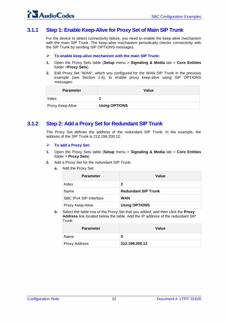
3.1.1 Step 1: Enable Keep-Alive for Proxy Set of Main SIP Trunk For the device to detect connectivity failure, you need to enable the keep-alive mechanism with the main SIP Trunk. The keep-alive mechanism periodically checks connectivity with the SIP Trunk by sending SIP OPTIONS messages.
To enable keep-alive mechanism with the main SIP Trunk:
1. Open the Proxy Sets table (Setup menu > Signaling & Media tab > Core Entities folder >Proxy Sets).
2. Edit Proxy Set "WAN", which you configured for the WAN SIP Trunk in the previous example (see Section 2.6), to enable proxy keep-alive using SIP OPTIONS messages:
Parameter Value
Index 1
Proxy Keep-Alive Using OPTIONS
3.1.2 Step 2: Add a Proxy Set for Redundant SIP Trunk The Proxy Set defines the address of the redundant SIP Trunk. In the example, the address of the SIP Trunk is 212.199.200.12.
To add a Proxy Set:
1. Open the Proxy Sets table (Setup menu > Signaling & Media tab > Core Entities folder > Proxy Sets)
2. Add a Proxy Set for the redundant SIP Trunk: a. Add the Proxy Set:
Parameter Value
Index 2
Name Redundant SIP Trunk
SBC IPv4 SIP Interface WAN
Proxy Keep-Alive Using OPTIONS b. Select the table row of the Proxy Set that you added, and then click the Proxy
Address link located below the table. Add the IP address of the redundant SIP Trunk:
Parameter Value
Name 0
Proxy Address 212.199.200.12
Version 7.2 23 Mediant Gateway & SBC Series
Configuration Note 3. Alternative Routing upon SIP Trunk Failure
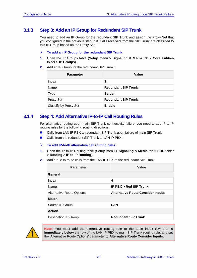
3.1.3 Step 3: Add an IP Group for Redundant SIP Trunk You need to add an IP Group for the redundant SIP Trunk and assign the Proxy Set that you configured in the previous step to it. Calls received from the SIP Trunk are classified to this IP Group based on the Proxy Set.
To add an IP Group for the redundant SIP Trunk:
1. Open the IP Groups table (Setup menu > Signaling & Media tab > Core Entities folder > IP Groups).
2. Add an IP Group for the redundant SIP Trunk:
Parameter Value
Index 3
Name Redundant SIP Trunk
Type Server
Proxy Set Redundant SIP Trunk
Classify by Proxy Set Enable
3.1.4 Step 4: Add Alternative IP-to-IP Call Routing Rules For alternative routing upon main SIP Trunk connectivity failure, you need to add IP-to-IP routing rules for the following routing directions: Calls from LAN IP PBX to redundant SIP Trunk upon failure of main SIP Trunk. Calls from the redundant SIP Trunk to LAN IP PBX.
To add IP-to-IP alternative call routing rules:
1. Open the IP-to-IP Routing table (Setup menu > Signaling & Media tab > SBC folder > Routing > IP-to-IP Routing).
2. Add a rule to route calls from the LAN IP PBX to the redundant SIP Trunk:
Parameter Value
General
Index 4
Name IP PBX > Red SIP Trunk
Alternative Route Options Alternative Route Consider Inputs
Match
Source IP Group LAN
Action
Destination IP Group Redundant SIP Trunk
Note: You must add the alternative routing rule to the table index row that is immediately below the row of the LAN IP PBX to main SIP Trunk routing rule, and set the 'Alternative Route Options' parameter to Alternative Route Consider Inputs.
Configuration Note 24 Document #: LTRT-31626
SBC Configuration Examples
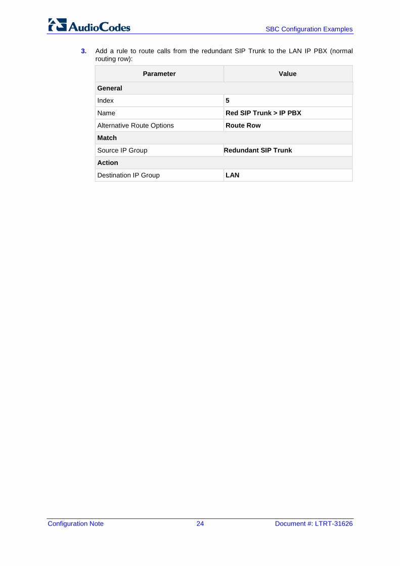
3. Add a rule to route calls from the redundant SIP Trunk to the LAN IP PBX (normal routing row):
Parameter Value
General
Index 5
Name Red SIP Trunk > IP PBX
Alternative Route Options Route Row
Match
Source IP Group Redundant SIP Trunk
Action
Destination IP Group LAN
Version 7.2 25 Mediant Gateway & SBC Series
Configuration Note 3. Alternative Routing upon SIP Trunk Failure
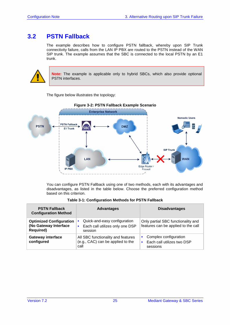
3.2 PSTN Fallback The example describes how to configure PSTN fallback, whereby upon SIP Trunk connectivity failure, calls from the LAN IP PBX are routed to the PSTN instead of the WAN SIP trunk. The example assumes that the SBC is connected to the local PSTN by an E1 trunk.
Note: The example is applicable only to hybrid SBCs, which also provide optional PSTN interfaces.
The figure below illustrates the topology:
Figure 3-2: PSTN Fallback Example Scenario
You can configure PSTN Fallback using one of two methods, each with its advantages and disadvantages, as listed in the table below. Choose the preferred configuration method based on this criterion.
Table 3-1: Configuration Methods for PSTN Fallback
PSTN Fallback Configuration Method
Advantages Disadvantages
Optimized Configuration (No Gateway Interface Required)
Quick-and-easy configuration Each call utilizes only one DSP
session
Only partial SBC functionality and features can be applied to the call
Gateway interface configured
All SBC functionality and features (e.g., CAC) can be applied to the call
Complex configuration Each call utilizes two DSP
sessions
Configuration Note 26 Document #: LTRT-31626
SBC Configuration Examples
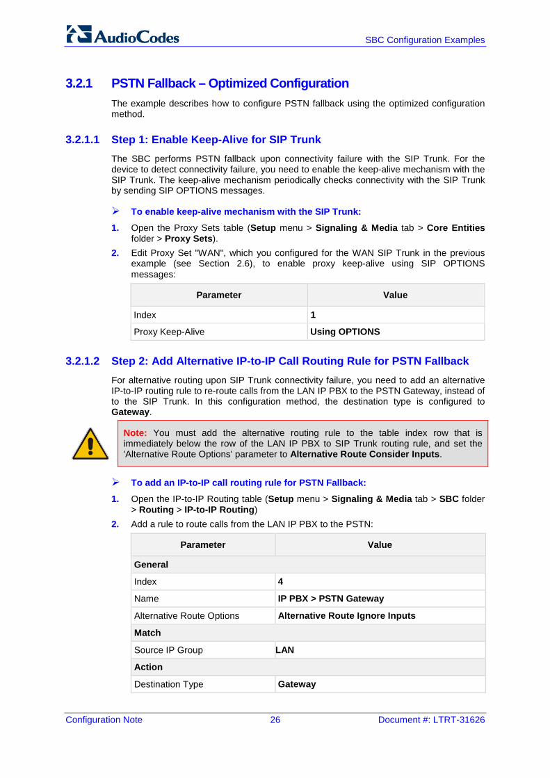
3.2.1 PSTN Fallback – Optimized Configuration The example describes how to configure PSTN fallback using the optimized configuration method.
3.2.1.1 Step 1: Enable Keep-Alive for SIP Trunk The SBC performs PSTN fallback upon connectivity failure with the SIP Trunk. For the device to detect connectivity failure, you need to enable the keep-alive mechanism with the SIP Trunk. The keep-alive mechanism periodically checks connectivity with the SIP Trunk by sending SIP OPTIONS messages.
To enable keep-alive mechanism with the SIP Trunk:
1. Open the Proxy Sets table (Setup menu > Signaling & Media tab > Core Entities folder > Proxy Sets).
2. Edit Proxy Set "WAN", which you configured for the WAN SIP Trunk in the previous example (see Section 2.6), to enable proxy keep-alive using SIP OPTIONS messages:
Parameter Value
Index 1
Proxy Keep-Alive Using OPTIONS
3.2.1.2 Step 2: Add Alternative IP-to-IP Call Routing Rule for PSTN Fallback For alternative routing upon SIP Trunk connectivity failure, you need to add an alternative IP-to-IP routing rule to re-route calls from the LAN IP PBX to the PSTN Gateway, instead of to the SIP Trunk. In this configuration method, the destination type is configured to Gateway.
Note: You must add the alternative routing rule to the table index row that is immediately below the row of the LAN IP PBX to SIP Trunk routing rule, and set the 'Alternative Route Options' parameter to Alternative Route Consider Inputs.
To add an IP-to-IP call routing rule for PSTN Fallback:
1. Open the IP-to-IP Routing table (Setup menu > Signaling & Media tab > SBC folder > Routing > IP-to-IP Routing)
2. Add a rule to route calls from the LAN IP PBX to the PSTN:
Parameter Value
General
Index 4
Name IP PBX > PSTN Gateway
Alternative Route Options Alternative Route Ignore Inputs
Match
Source IP Group LAN
Action
Destination Type Gateway
Version 7.2 27 Mediant Gateway & SBC Series
Configuration Note 3. Alternative Routing upon SIP Trunk Failure
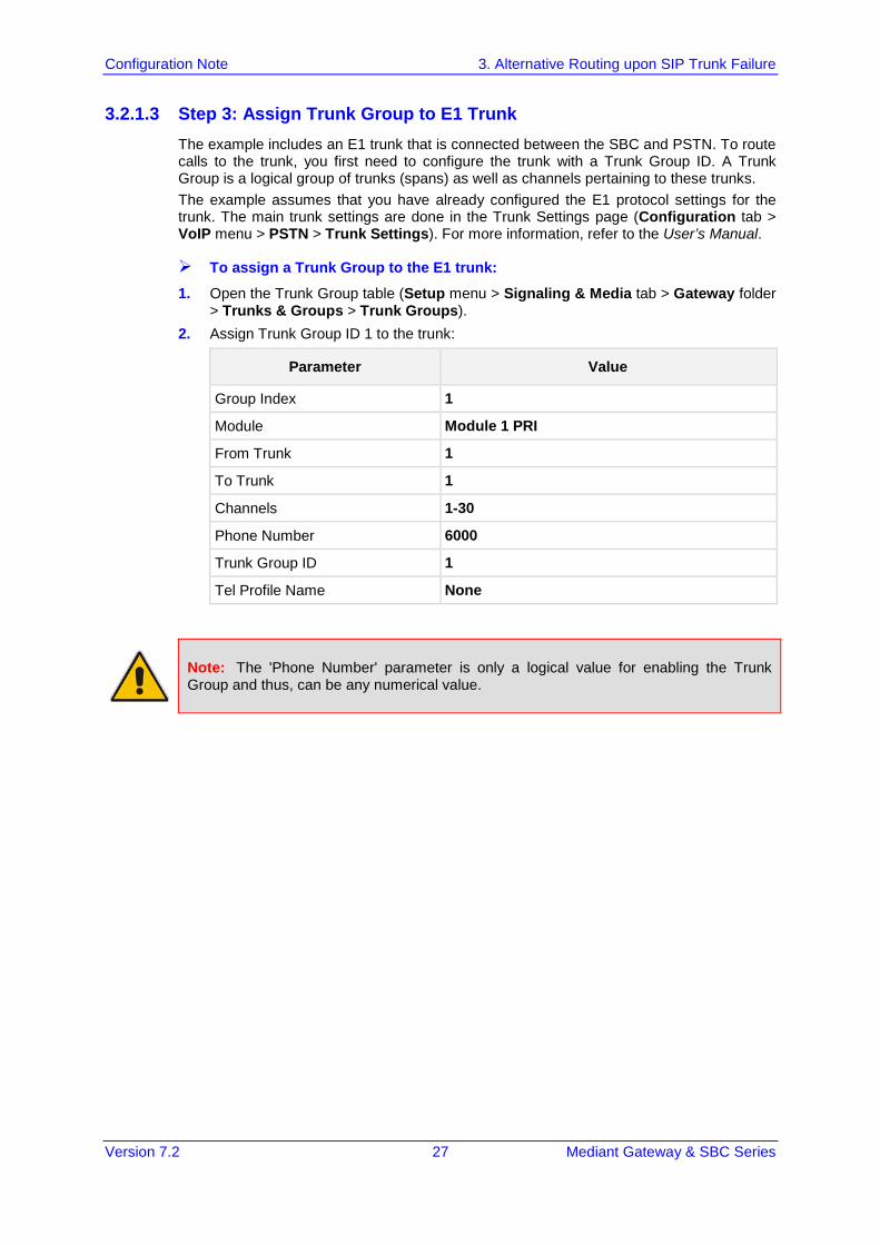
3.2.1.3 Step 3: Assign Trunk Group to E1 Trunk The example includes an E1 trunk that is connected between the SBC and PSTN. To route calls to the trunk, you first need to configure the trunk with a Trunk Group ID. A Trunk Group is a logical group of trunks (spans) as well as channels pertaining to these trunks. The example assumes that you have already configured the E1 protocol settings for the trunk. The main trunk settings are done in the Trunk Settings page (Configuration tab > VoIP menu > PSTN > Trunk Settings). For more information, refer to the User’s Manual.
To assign a Trunk Group to the E1 trunk:
1. Open the Trunk Group table (Setup menu > Signaling & Media tab > Gateway folder > Trunks & Groups > Trunk Groups).
2. Assign Trunk Group ID 1 to the trunk:
Parameter Value
Group Index 1
Module Module 1 PRI
From Trunk 1
To Trunk 1
Channels 1-30
Phone Number 6000
Trunk Group ID 1
Tel Profile Name None
Note: The 'Phone Number' parameter is only a logical value for enabling the Trunk Group and thus, can be any numerical value.
Configuration Note 28 Document #: LTRT-31626
SBC Configuration Examples
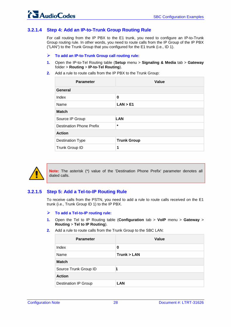
3.2.1.4 Step 4: Add an IP-to-Trunk Group Routing Rule For call routing from the IP PBX to the E1 trunk, you need to configure an IP-to-Trunk Group routing rule. In other words, you need to route calls from the IP Group of the IP PBX ("LAN") to the Trunk Group that you configured for the E1 trunk (i.e., ID 1).
To add an IP-to-Trunk Group call routing rule:
1. Open the IP-to-Tel Routing table (Setup menu > Signaling & Media tab > Gateway folder > Routing > IP-to-Tel Routing).
2. Add a rule to route calls from the IP PBX to the Trunk Group:
Parameter Value
General
Index 0
Name LAN > E1
Match
Source IP Group LAN
Destination Phone Prefix *
Action
Destination Type Trunk Group
Trunk Group ID 1
Note: The asterisk (*) value of the 'Destination Phone Prefix' parameter denotes all dialed calls.
3.2.1.5 Step 5: Add a Tel-to-IP Routing Rule To receive calls from the PSTN, you need to add a rule to route calls received on the E1 trunk (i.e., Trunk Group ID 1) to the IP PBX.
To add a Tel-to-IP routing rule:
1. Open the Tel to IP Routing table (Configuration tab > VoIP menu > Gateway > Routing > Tel to IP Routing).
2. Add a rule to route calls from the Trunk Group to the SBC LAN:
Parameter Value
Index 0
Name Trunk > LAN
Match
Source Trunk Group ID 1
Action
Destination IP Group LAN
Version 7.2 29 Mediant Gateway & SBC Series
Configuration Note 3. Alternative Routing upon SIP Trunk Failure
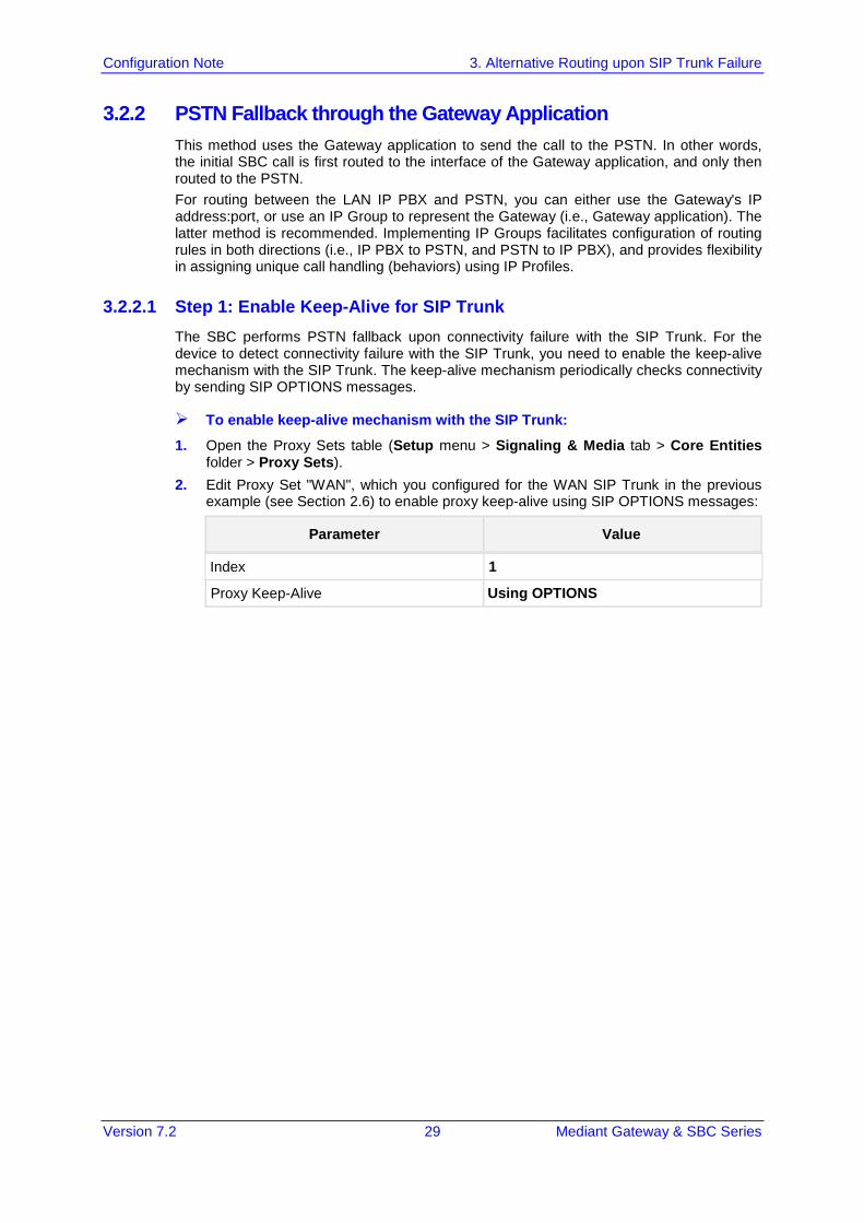
3.2.2 PSTN Fallback through the Gateway Application This method uses the Gateway application to send the call to the PSTN. In other words, the initial SBC call is first routed to the interface of the Gateway application, and only then routed to the PSTN. For routing between the LAN IP PBX and PSTN, you can either use the Gateway's IP address:port, or use an IP Group to represent the Gateway (i.e., Gateway application). The latter method is recommended. Implementing IP Groups facilitates configuration of routing rules in both directions (i.e., IP PBX to PSTN, and PSTN to IP PBX), and provides flexibility in assigning unique call handling (behaviors) using IP Profiles.
3.2.2.1 Step 1: Enable Keep-Alive for SIP Trunk The SBC performs PSTN fallback upon connectivity failure with the SIP Trunk. For the device to detect connectivity failure with the SIP Trunk, you need to enable the keep-alive mechanism with the SIP Trunk. The keep-alive mechanism periodically checks connectivity by sending SIP OPTIONS messages.
To enable keep-alive mechanism with the SIP Trunk:
1. Open the Proxy Sets table (Setup menu > Signaling & Media tab > Core Entities folder > Proxy Sets).
2. Edit Proxy Set "WAN", which you configured for the WAN SIP Trunk in the previous example (see Section 2.6) to enable proxy keep-alive using SIP OPTIONS messages:
Parameter Value
Proxy Keep-Alive Using OPTIONS
Index 1

Configuration Note 30 Document #: LTRT-31626
SBC Configuration Examples
3.2.2.2 Step 2: Add a SIP Interface for PSTN Gateway You need to add a SIP Interface for the Gateway application. The SIP Interface is used for the listening port of SIP messages destined to the Gateway application.
To add a SIP Interface for PSTN Gateway:
1. Open the SIP Interfaces table (Setup menu > Signaling & Media tab > Core Entities folder > SIP Interfaces).
2. Add a SIP Interface for the Gateway application:
Parameter Value
Index 2
Name PSTN Gateway
Network Interface LAN
Application Type GW
UDP Port 5070
TCP Port 5070
TLS Port 5071
Media Realm LAN
Note:
• As the SIP Interface is for the LAN, it is assigned the "LAN" interface. • The 'Application Type' parameter defines that it's for the Gateway application.
Version 7.2 31 Mediant Gateway & SBC Series
Configuration Note 3. Alternative Routing upon SIP Trunk Failure
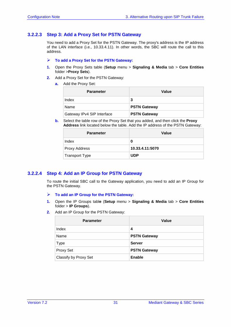
3.2.2.3 Step 3: Add a Proxy Set for PSTN Gateway You need to add a Proxy Set for the PSTN Gateway. The proxy's address is the IP address of the LAN interface (i.e., 10.33.4.11). In other words, the SBC will route the call to this address.
To add a Proxy Set for the PSTN Gateway:
1. Open the Proxy Sets table (Setup menu > Signaling & Media tab > Core Entities folder >Proxy Sets).
2. Add a Proxy Set for the PSTN Gateway: a. Add the Proxy Set:
Parameter Value
Index 3
Name PSTN Gateway
Gateway IPv4 SIP Interface PSTN Gateway b. Select the table row of the Proxy Set that you added, and then click the Proxy
Address link located below the table. Add the IP address of the PSTN Gateway:
Parameter Value
Index 0
Proxy Address 10.33.4.11:5070
Transport Type UDP
3.2.2.4 Step 4: Add an IP Group for PSTN Gateway To route the initial SBC call to the Gateway application, you need to add an IP Group for the PSTN Gateway.
To add an IP Group for the PSTN Gateway:
1. Open the IP Groups table (Setup menu > Signaling & Media tab > Core Entities folder > IP Groups).
2. Add an IP Group for the PSTN Gateway:
Parameter Value
Index 4
Name PSTN Gateway
Type Server
Proxy Set PSTN Gateway
Classify by Proxy Set Enable
Configuration Note 32 Document #: LTRT-31626
SBC Configuration Examples
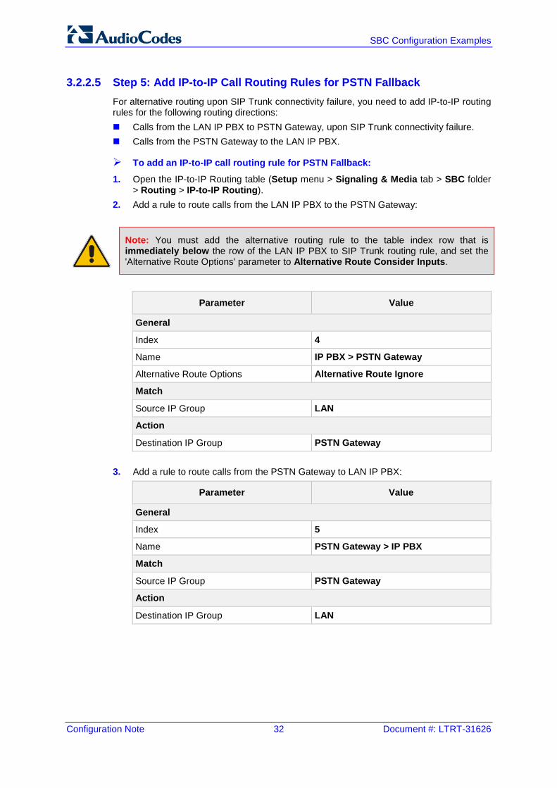
3.2.2.5 Step 5: Add IP-to-IP Call Routing Rules for PSTN Fallback For alternative routing upon SIP Trunk connectivity failure, you need to add IP-to-IP routing rules for the following routing directions: Calls from the LAN IP PBX to PSTN Gateway, upon SIP Trunk connectivity failure. Calls from the PSTN Gateway to the LAN IP PBX.
To add an IP-to-IP call routing rule for PSTN Fallback:
1. Open the IP-to-IP Routing table (Setup menu > Signaling & Media tab > SBC folder > Routing > IP-to-IP Routing).
2. Add a rule to route calls from the LAN IP PBX to the PSTN Gateway:
Note: You must add the alternative routing rule to the table index row that is immediately below the row of the LAN IP PBX to SIP Trunk routing rule, and set the 'Alternative Route Options' parameter to Alternative Route Consider Inputs.
Parameter Value
General
Index 4
Name IP PBX > PSTN Gateway
Alternative Route Options Alternative Route Ignore
Match
Source IP Group LAN
Action
Destination IP Group PSTN Gateway
3. Add a rule to route calls from the PSTN Gateway to LAN IP PBX:
Parameter Value
General
Index 5
Name PSTN Gateway > IP PBX
Match
Source IP Group PSTN Gateway
Action
Destination IP Group LAN
Version 7.2 33 Mediant Gateway & SBC Series
Configuration Note 3. Alternative Routing upon SIP Trunk Failure
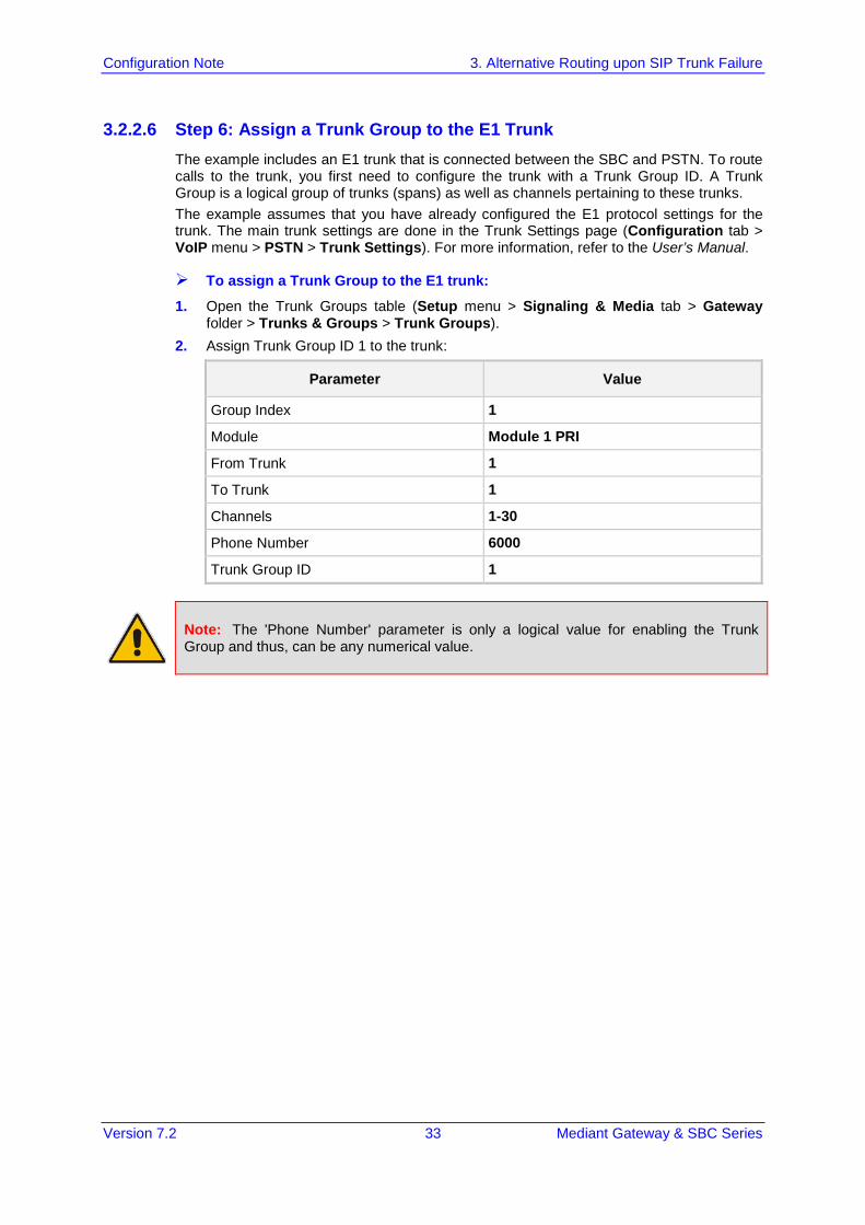
3.2.2.6 Step 6: Assign a Trunk Group to the E1 Trunk The example includes an E1 trunk that is connected between the SBC and PSTN. To route calls to the trunk, you first need to configure the trunk with a Trunk Group ID. A Trunk Group is a logical group of trunks (spans) as well as channels pertaining to these trunks. The example assumes that you have already configured the E1 protocol settings for the trunk. The main trunk settings are done in the Trunk Settings page (Configuration tab > VoIP menu > PSTN > Trunk Settings). For more information, refer to the User’s Manual.
To assign a Trunk Group to the E1 trunk:
1. Open the Trunk Groups table (Setup menu > Signaling & Media tab > Gateway folder > Trunks & Groups > Trunk Groups).
2. Assign Trunk Group ID 1 to the trunk:
Parameter Value
Group Index 1
Module Module 1 PRI
From Trunk 1
To Trunk 1
Channels 1-30
Phone Number 6000
Trunk Group ID 1
Note: The 'Phone Number' parameter is only a logical value for enabling the Trunk Group and thus, can be any numerical value.
Configuration Note 34 Document #: LTRT-31626
SBC Configuration Examples
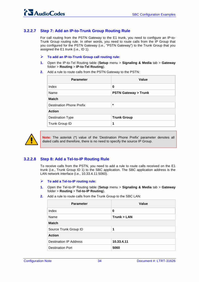
3.2.2.7 Step 7: Add an IP-to-Trunk Group Routing Rule For call routing from the PSTN Gateway to the E1 trunk, you need to configure an IP-to-Trunk Group routing rule. In other words, you need to route calls from the IP Group that you configured for the PSTN Gateway (i.e., "PSTN Gateway") to the Trunk Group that you assigned the E1 trunk (i.e., ID 1).
To add an IP-to-Trunk Group call routing rule:
1. Open the IP-to-Tel Routing table (Setup menu > Signaling & Media tab > Gateway folder > Routing > IP-to-Tel Routing).
2. Add a rule to route calls from the PSTN Gateway to the PSTN:
Parameter Value
Index 0
Name PSTN Gateway > Trunk
Match
Destination Phone Prefix *
Action
Destination Type Trunk Group
Trunk Group ID 1
Note: The asterisk (*) value of the 'Destination Phone Prefix' parameter denotes all dialed calls and therefore, there is no need to specify the source IP Group.
3.2.2.8 Step 8: Add a Tel-to-IP Routing Rule To receive calls from the PSTN, you need to add a rule to route calls received on the E1 trunk (i.e., Trunk Group ID 1) to the SBC application. The SBC application address is the LAN network interface (i.e., 10.33.4.11:5060).
To add a Tel-to-IP routing rule:
1. Open the Tel-to-IP Routing table (Setup menu > Signaling & Media tab > Gateway folder > Routing > Tel-to-IP Routing).
2. Add a rule to route calls from the Trunk Group to the SBC LAN:
Parameter Value
Index 0
Name Trunk > LAN
Match
Source Trunk Group ID 1
Action
Destination IP Address 10.33.4.11
Destination Port 5060
Version 7.2 35 Mediant Gateway & SBC Series
Configuration Note 4. Hosted WAN IP PBX
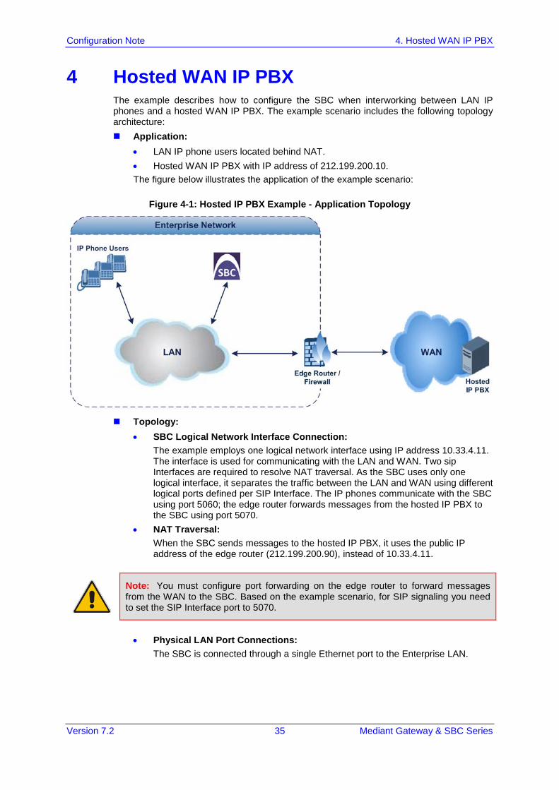
4 Hosted WAN IP PBX The example describes how to configure the SBC when interworking between LAN IP phones and a hosted WAN IP PBX. The example scenario includes the following topology architecture: Application:
• LAN IP phone users located behind NAT. • Hosted WAN IP PBX with IP address of 212.199.200.10. The figure below illustrates the application of the example scenario:
Figure 4-1: Hosted IP PBX Example - Application Topology
Topology:
• SBC Logical Network Interface Connection: The example employs one logical network interface using IP address 10.33.4.11. The interface is used for communicating with the LAN and WAN. Two sip Interfaces are required to resolve NAT traversal. As the SBC uses only one logical interface, it separates the traffic between the LAN and WAN using different logical ports defined per SIP Interface. The IP phones communicate with the SBC using port 5060; the edge router forwards messages from the hosted IP PBX to the SBC using port 5070.
• NAT Traversal: When the SBC sends messages to the hosted IP PBX, it uses the public IP address of the edge router (212.199.200.90), instead of 10.33.4.11.
Note: You must configure port forwarding on the edge router to forward messages from the WAN to the SBC. Based on the example scenario, for SIP signaling you need to set the SIP Interface port to 5070.
• Physical LAN Port Connections:
The SBC is connected through a single Ethernet port to the Enterprise LAN.
Configuration Note 36 Document #: LTRT-31626
SBC Configuration Examples
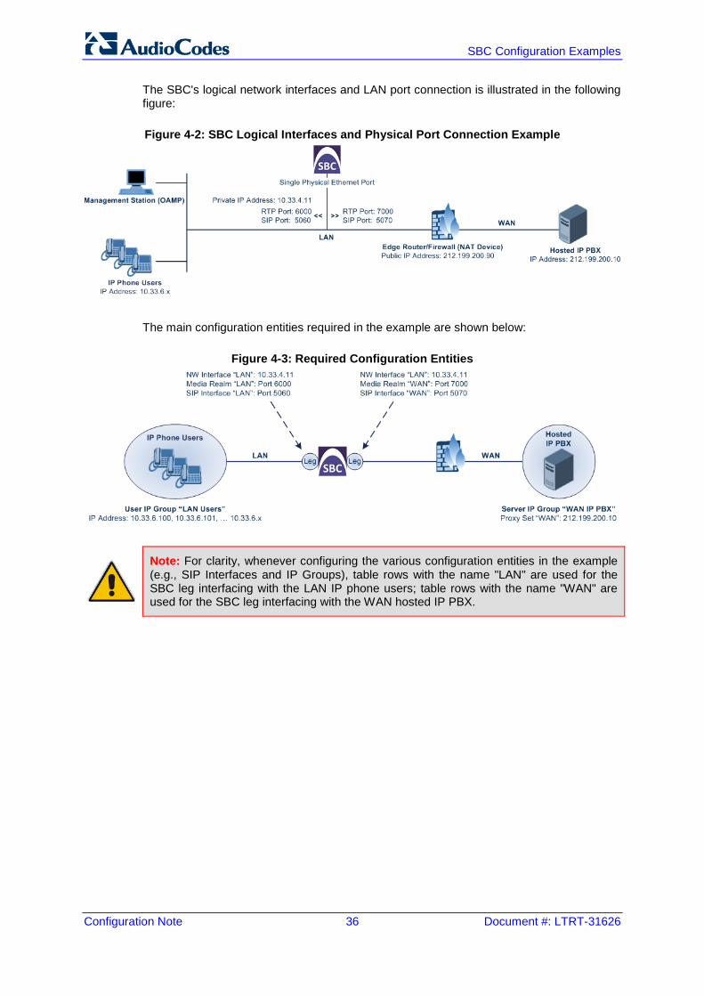
The SBC's logical network interfaces and LAN port connection is illustrated in the following figure:
Figure 4-2: SBC Logical Interfaces and Physical Port Connection Example
The main configuration entities required in the example are shown below:
Figure 4-3: Required Configuration Entities
Note: For clarity, whenever configuring the various configuration entities in the example (e.g., SIP Interfaces and IP Groups), table rows with the name "LAN" are used for the SBC leg interfacing with the LAN IP phone users; table rows with the name "WAN" are used for the SBC leg interfacing with the WAN hosted IP PBX.
Version 7.2 37 Mediant Gateway & SBC Series
Configuration Note 4. Hosted WAN IP PBX
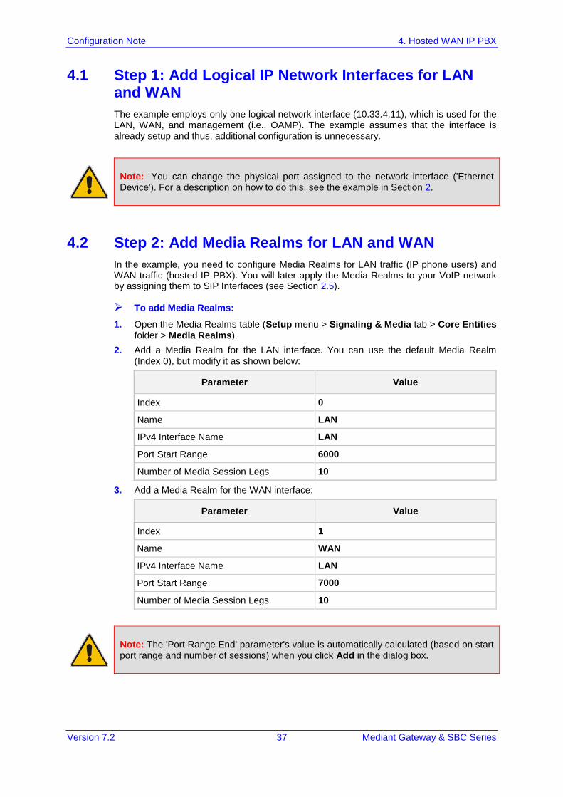
4.1 Step 1: Add Logical IP Network Interfaces for LAN and WAN The example employs only one logical network interface (10.33.4.11), which is used for the LAN, WAN, and management (i.e., OAMP). The example assumes that the interface is already setup and thus, additional configuration is unnecessary.
Note: You can change the physical port assigned to the network interface ('Ethernet Device'). For a description on how to do this, see the example in Section 2.
4.2 Step 2: Add Media Realms for LAN and WAN In the example, you need to configure Media Realms for LAN traffic (IP phone users) and WAN traffic (hosted IP PBX). You will later apply the Media Realms to your VoIP network by assigning them to SIP Interfaces (see Section 2.5).
To add Media Realms:
1. Open the Media Realms table (Setup menu > Signaling & Media tab > Core Entities folder > Media Realms).
2. Add a Media Realm for the LAN interface. You can use the default Media Realm (Index 0), but modify it as shown below:
Parameter Value
Index 0
Name LAN
IPv4 Interface Name LAN
Port Start Range 6000
Number of Media Session Legs 10
3. Add a Media Realm for the WAN interface:
Parameter Value
Index 1
Name WAN
IPv4 Interface Name LAN
Port Start Range 7000
Number of Media Session Legs 10
Note: The 'Port Range End' parameter's value is automatically calculated (based on start port range and number of sessions) when you click Add in the dialog box.
Configuration Note 38 Document #: LTRT-31626
SBC Configuration Examples
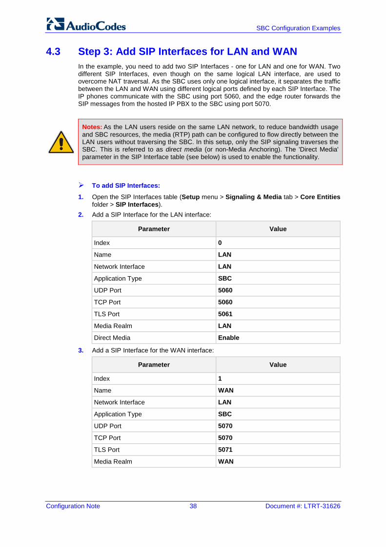
4.3 Step 3: Add SIP Interfaces for LAN and WAN In the example, you need to add two SIP Interfaces - one for LAN and one for WAN. Two different SIP Interfaces, even though on the same logical LAN interface, are used to overcome NAT traversal. As the SBC uses only one logical interface, it separates the traffic between the LAN and WAN using different logical ports defined by each SIP Interface. The IP phones communicate with the SBC using port 5060, and the edge router forwards the SIP messages from the hosted IP PBX to the SBC using port 5070.
Notes: As the LAN users reside on the same LAN network, to reduce bandwidth usage and SBC resources, the media (RTP) path can be configured to flow directly between the LAN users without traversing the SBC. In this setup, only the SIP signaling traverses the SBC. This is referred to as direct media (or non-Media Anchoring). The 'Direct Media' parameter in the SIP Interface table (see below) is used to enable the functionality.
To add SIP Interfaces:
1. Open the SIP Interfaces table (Setup menu > Signaling & Media tab > Core Entities folder > SIP Interfaces).
2. Add a SIP Interface for the LAN interface:
Parameter Value
Index 0
Name LAN
Network Interface LAN
Application Type SBC
UDP Port 5060
TCP Port 5060
TLS Port 5061
Media Realm LAN
Direct Media Enable
3. Add a SIP Interface for the WAN interface:
Parameter Value
Index 1
Name WAN
Network Interface LAN
Application Type SBC
UDP Port 5070
TCP Port 5070
TLS Port 5071
Media Realm WAN
Version 7.2 39 Mediant Gateway & SBC Series
Configuration Note 4. Hosted WAN IP PBX
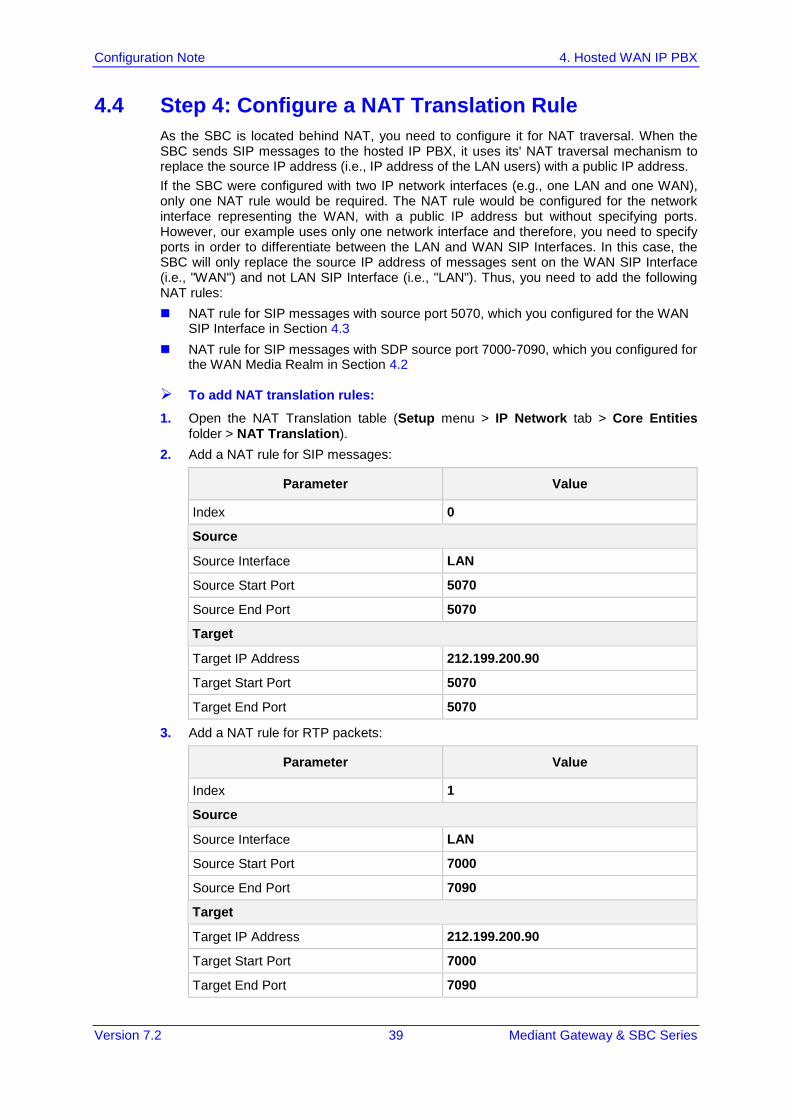
4.4 Step 4: Configure a NAT Translation Rule As the SBC is located behind NAT, you need to configure it for NAT traversal. When the SBC sends SIP messages to the hosted IP PBX, it uses its' NAT traversal mechanism to replace the source IP address (i.e., IP address of the LAN users) with a public IP address. If the SBC were configured with two IP network interfaces (e.g., one LAN and one WAN), only one NAT rule would be required. The NAT rule would be configured for the network interface representing the WAN, with a public IP address but without specifying ports. However, our example uses only one network interface and therefore, you need to specify ports in order to differentiate between the LAN and WAN SIP Interfaces. In this case, the SBC will only replace the source IP address of messages sent on the WAN SIP Interface (i.e., "WAN") and not LAN SIP Interface (i.e., "LAN"). Thus, you need to add the following NAT rules: NAT rule for SIP messages with source port 5070, which you configured for the WAN
SIP Interface in Section 4.3 NAT rule for SIP messages with SDP source port 7000-7090, which you configured for
the WAN Media Realm in Section 4.2
To add NAT translation rules:
1. Open the NAT Translation table (Setup menu > IP Network tab > Core Entities folder > NAT Translation).
2. Add a NAT rule for SIP messages:
Parameter Value
Index 0
Source
Source Interface LAN
Source Start Port 5070
Source End Port 5070
Target
Target IP Address 212.199.200.90
Target Start Port 5070
Target End Port 5070
3. Add a NAT rule for RTP packets:
Parameter Value
Index 1
Source
Source Interface LAN
Source Start Port 7000
Source End Port 7090
Target
Target IP Address 212.199.200.90
Target Start Port 7000
Target End Port 7090
Configuration Note 40 Document #: LTRT-31626
SBC Configuration Examples
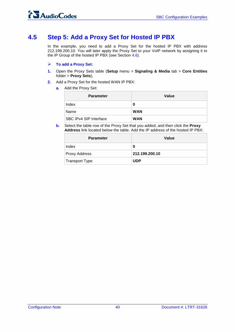
4.5 Step 5: Add a Proxy Set for Hosted IP PBX In the example, you need to add a Proxy Set for the hosted IP PBX with address 212.199.200.10. You will later apply the Proxy Set to your VoIP network by assigning it to the IP Group of the hosted IP PBX (see Section 4.6).
To add a Proxy Set:
1. Open the Proxy Sets table (Setup menu > Signaling & Media tab > Core Entities folder > Proxy Sets).
2. Add a Proxy Set for the hosted WAN IP PBX: a. Add the Proxy Set:
Parameter Value
Index 0
Name WAN
SBC IPv4 SIP Interface WAN b. Select the table row of the Proxy Set that you added, and then click the Proxy
Address link located below the table. Add the IP address of the hosted IP PBX:
Parameter Value
Index 0
Proxy Address 212.199.200.10
Transport Type UDP
Version 7.2 41 Mediant Gateway & SBC Series
Configuration Note 4. Hosted WAN IP PBX
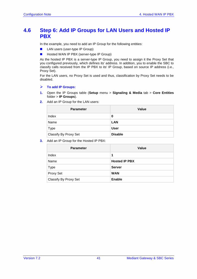
4.6 Step 6: Add IP Groups for LAN Users and Hosted IP PBX In the example, you need to add an IP Group for the following entities: LAN users (user-type IP Group) Hosted WAN IP PBX (server-type IP Group) As the hosted IP PBX is a server-type IP Group, you need to assign it the Proxy Set that you configured previously, which defines its' address. In addition, you to enable the SBC to classify calls received from the IP PBX to its' IP Group, based on source IP address (i.e., Proxy Set). For the LAN users, no Proxy Set is used and thus, classification by Proxy Set needs to be disabled.
To add IP Groups:
1. Open the IP Groups table (Setup menu > Signaling & Media tab > Core Entities folder > IP Groups).
2. Add an IP Group for the LAN users:
Parameter Value
Index 0
Name LAN
Type User
Classify By Proxy Set Disable
3. Add an IP Group for the Hosted IP PBX:
Parameter Value
Index 1
Name Hosted IP PBX
Type Server
Proxy Set WAN
Classify By Proxy Set Enable
Configuration Note 42 Document #: LTRT-31626
SBC Configuration Examples
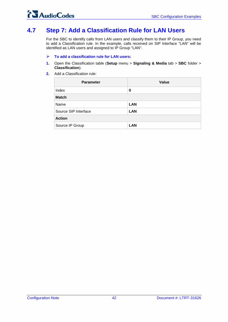
4.7 Step 7: Add a Classification Rule for LAN Users For the SBC to identify calls from LAN users and classify them to their IP Group, you need to add a Classification rule. In the example, calls received on SIP Interface "LAN" will be identified as LAN users and assigned to IP Group "LAN".
To add a classification rule for LAN users:
1. Open the Classification table (Setup menu > Signaling & Media tab > SBC folder > Classification).
2. Add a Classification rule:
Parameter Value
Index 0
Match
Name LAN
Source SIP Interface LAN
Action
Source IP Group LAN
Version 7.2 43 Mediant Gateway & SBC Series
Configuration Note 4. Hosted WAN IP PBX
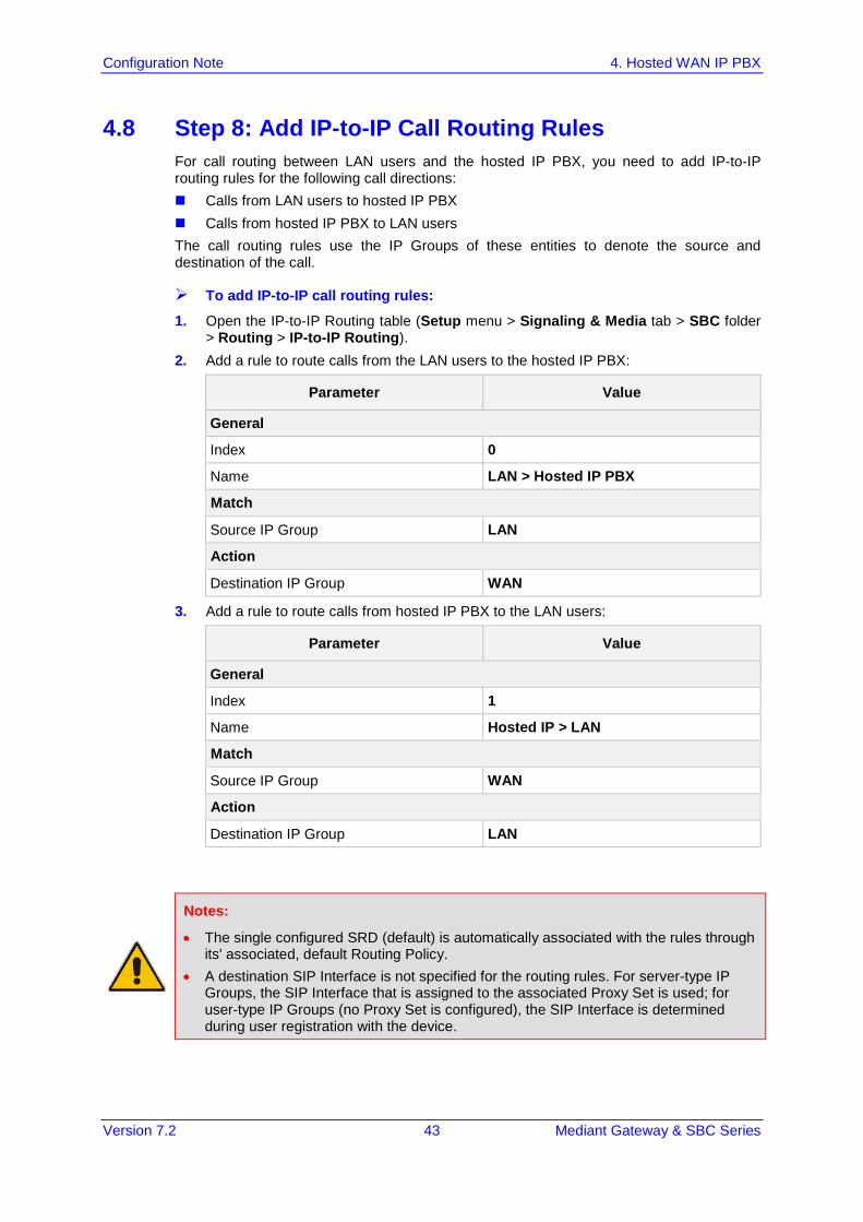
4.8 Step 8: Add IP-to-IP Call Routing Rules For call routing between LAN users and the hosted IP PBX, you need to add IP-to-IP routing rules for the following call directions: Calls from LAN users to hosted IP PBX Calls from hosted IP PBX to LAN users The call routing rules use the IP Groups of these entities to denote the source and destination of the call.
To add IP-to-IP call routing rules:
1. Open the IP-to-IP Routing table (Setup menu > Signaling & Media tab > SBC folder > Routing > IP-to-IP Routing).
2. Add a rule to route calls from the LAN users to the hosted IP PBX:
Parameter Value
General
Index 0
Name LAN > Hosted IP PBX
Match
Source IP Group LAN
Action
Destination IP Group WAN
3. Add a rule to route calls from hosted IP PBX to the LAN users:
Parameter Value
General
Index 1
Name Hosted IP > LAN
Match
Source IP Group WAN
Action
Destination IP Group LAN
Notes:
• The single configured SRD (default) is automatically associated with the rules through its' associated, default Routing Policy.
• A destination SIP Interface is not specified for the routing rules. For server-type IP Groups, the SIP Interface that is assigned to the associated Proxy Set is used; for user-type IP Groups (no Proxy Set is configured), the SIP Interface is determined during user registration with the device.

Configuration Note 44 Document #: LTRT-31626
SBC Configuration Examples
This page is intentionally left blank.
Version 7.2 45 Mediant Gateway & SBC Series
Configuration Note 5. Call Survivability for LAN Users upon Hosted IP PBX Failure
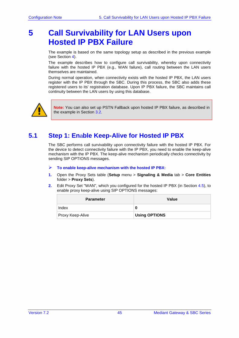
5 Call Survivability for LAN Users upon Hosted IP PBX Failure The example is based on the same topology setup as described in the previous example (see Section 4). The example describes how to configure call survivability, whereby upon connectivity failure with the hosted IP PBX (e.g., WAN failure), call routing between the LAN users themselves are maintained. During normal operation, when connectivity exists with the hosted IP PBX, the LAN users register with the IP PBX through the SBC. During this process, the SBC also adds these registered users to its' registration database. Upon IP PBX failure, the SBC maintains call continuity between the LAN users by using this database.
Note: You can also set up PSTN Fallback upon hosted IP PBX failure, as described in the example in Section 3.2.
5.1 Step 1: Enable Keep-Alive for Hosted IP PBX The SBC performs call survivability upon connectivity failure with the hosted IP PBX. For the device to detect connectivity failure with the IP PBX, you need to enable the keep-alive mechanism with the IP PBX. The keep-alive mechanism periodically checks connectivity by sending SIP OPTIONS messages.
To enable keep-alive mechanism with the hosted IP PBX:
1. Open the Proxy Sets table (Setup menu > Signaling & Media tab > Core Entities folder > Proxy Sets).
2. Edit Proxy Set "WAN", which you configured for the hosted IP PBX (in Section 4.5), to enable proxy keep-alive using SIP OPTIONS messages:
Parameter Value
Index 0
Proxy Keep-Alive Using OPTIONS
Configuration Note 46 Document #: LTRT-31626
SBC Configuration Examples
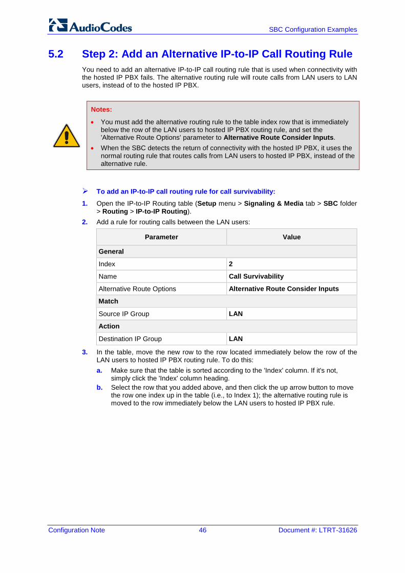
5.2 Step 2: Add an Alternative IP-to-IP Call Routing Rule You need to add an alternative IP-to-IP call routing rule that is used when connectivity with the hosted IP PBX fails. The alternative routing rule will route calls from LAN users to LAN users, instead of to the hosted IP PBX.
Notes:
• You must add the alternative routing rule to the table index row that is immediately below the row of the LAN users to hosted IP PBX routing rule, and set the 'Alternative Route Options' parameter to Alternative Route Consider Inputs.
• When the SBC detects the return of connectivity with the hosted IP PBX, it uses the normal routing rule that routes calls from LAN users to hosted IP PBX, instead of the alternative rule.
To add an IP-to-IP call routing rule for call survivability:
1. Open the IP-to-IP Routing table (Setup menu > Signaling & Media tab > SBC folder > Routing > IP-to-IP Routing).
2. Add a rule for routing calls between the LAN users:
Parameter Value
General
Index 2
Name Call Survivability
Alternative Route Options Alternative Route Consider Inputs
Match
Source IP Group LAN
Action
Destination IP Group LAN
3. In the table, move the new row to the row located immediately below the row of the LAN users to hosted IP PBX routing rule. To do this: a. Make sure that the table is sorted according to the 'Index' column. If it's not,
simply click the 'Index' column heading. b. Select the row that you added above, and then click the up arrow button to move
the row one index up in the table (i.e., to Index 1); the alternative routing rule is moved to the row immediately below the LAN users to hosted IP PBX rule.
Version 7.2 47 Mediant Gateway & SBC Series
Configuration Note 6. SIP Normalization between SIP Entity Servers
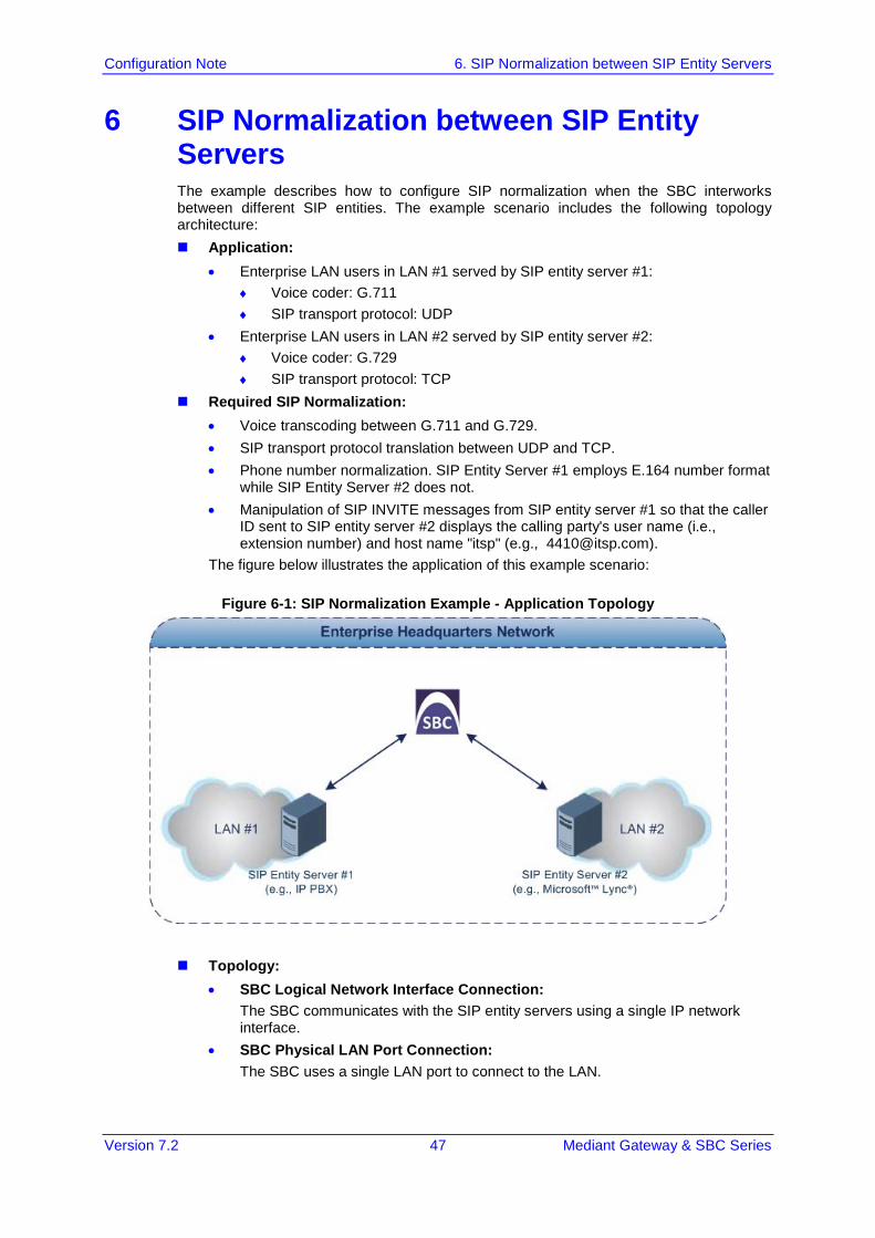
6 SIP Normalization between SIP Entity Servers The example describes how to configure SIP normalization when the SBC interworks between different SIP entities. The example scenario includes the following topology architecture: Application:
• Enterprise LAN users in LAN #1 served by SIP entity server #1: ♦ Voice coder: G.711 ♦ SIP transport protocol: UDP
• Enterprise LAN users in LAN #2 served by SIP entity server #2: ♦ Voice coder: G.729 ♦ SIP transport protocol: TCP
Required SIP Normalization: • Voice transcoding between G.711 and G.729. • SIP transport protocol translation between UDP and TCP. • Phone number normalization. SIP Entity Server #1 employs E.164 number format
while SIP Entity Server #2 does not. • Manipulation of SIP INVITE messages from SIP entity server #1 so that the caller
ID sent to SIP entity server #2 displays the calling party's user name (i.e., extension number) and host name "itsp" (e.g., [email protected]).
The figure below illustrates the application of this example scenario:
Figure 6-1: SIP Normalization Example - Application Topology
Topology: • SBC Logical Network Interface Connection:
The SBC communicates with the SIP entity servers using a single IP network interface.
• SBC Physical LAN Port Connection: The SBC uses a single LAN port to connect to the LAN.
Configuration Note 48 Document #: LTRT-31626
SBC Configuration Examples
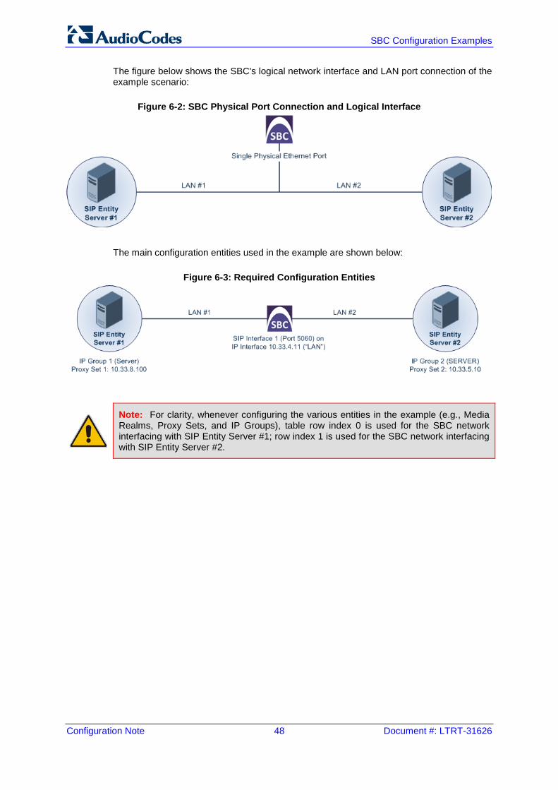
The figure below shows the SBC's logical network interface and LAN port connection of the example scenario:
Figure 6-2: SBC Physical Port Connection and Logical Interface
The main configuration entities used in the example are shown below:
Figure 6-3: Required Configuration Entities
Note: For clarity, whenever configuring the various entities in the example (e.g., Media Realms, Proxy Sets, and IP Groups), table row index 0 is used for the SBC network interfacing with SIP Entity Server #1; row index 1 is used for the SBC network interfacing with SIP Entity Server #2.
Version 7.2 49 Mediant Gateway & SBC Series
Configuration Note 6. SIP Normalization between SIP Entity Servers
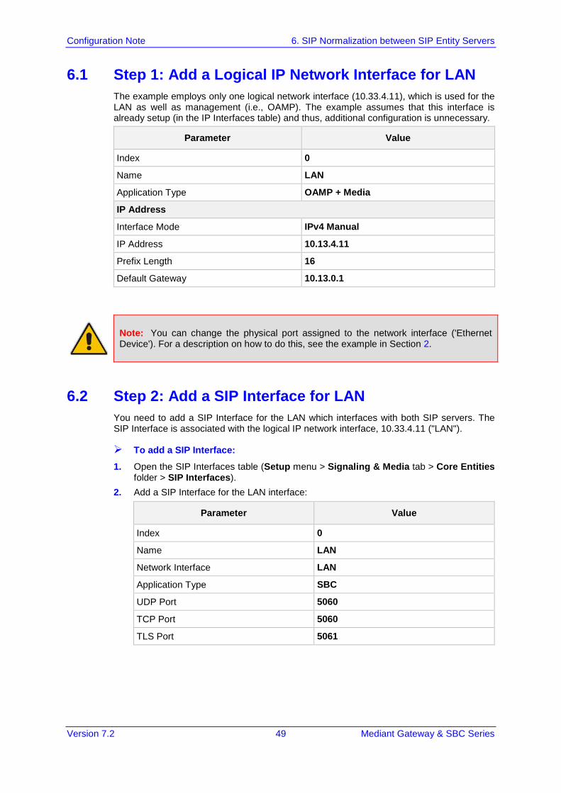
6.1 Step 1: Add a Logical IP Network Interface for LAN The example employs only one logical network interface (10.33.4.11), which is used for the LAN as well as management (i.e., OAMP). The example assumes that this interface is already setup (in the IP Interfaces table) and thus, additional configuration is unnecessary.
Parameter Value
Index 0
Name LAN
Application Type OAMP + Media
IP Address
Interface Mode IPv4 Manual
IP Address 10.13.4.11
Prefix Length 16
Default Gateway 10.13.0.1
Note: You can change the physical port assigned to the network interface ('Ethernet Device'). For a description on how to do this, see the example in Section 2.
6.2 Step 2: Add a SIP Interface for LAN You need to add a SIP Interface for the LAN which interfaces with both SIP servers. The SIP Interface is associated with the logical IP network interface, 10.33.4.11 ("LAN").
To add a SIP Interface:
1. Open the SIP Interfaces table (Setup menu > Signaling & Media tab > Core Entities folder > SIP Interfaces).
2. Add a SIP Interface for the LAN interface:
Parameter Value
Index 0
Name LAN
Network Interface LAN
Application Type SBC
UDP Port 5060
TCP Port 5060
TLS Port 5061
Configuration Note 50 Document #: LTRT-31626
SBC Configuration Examples
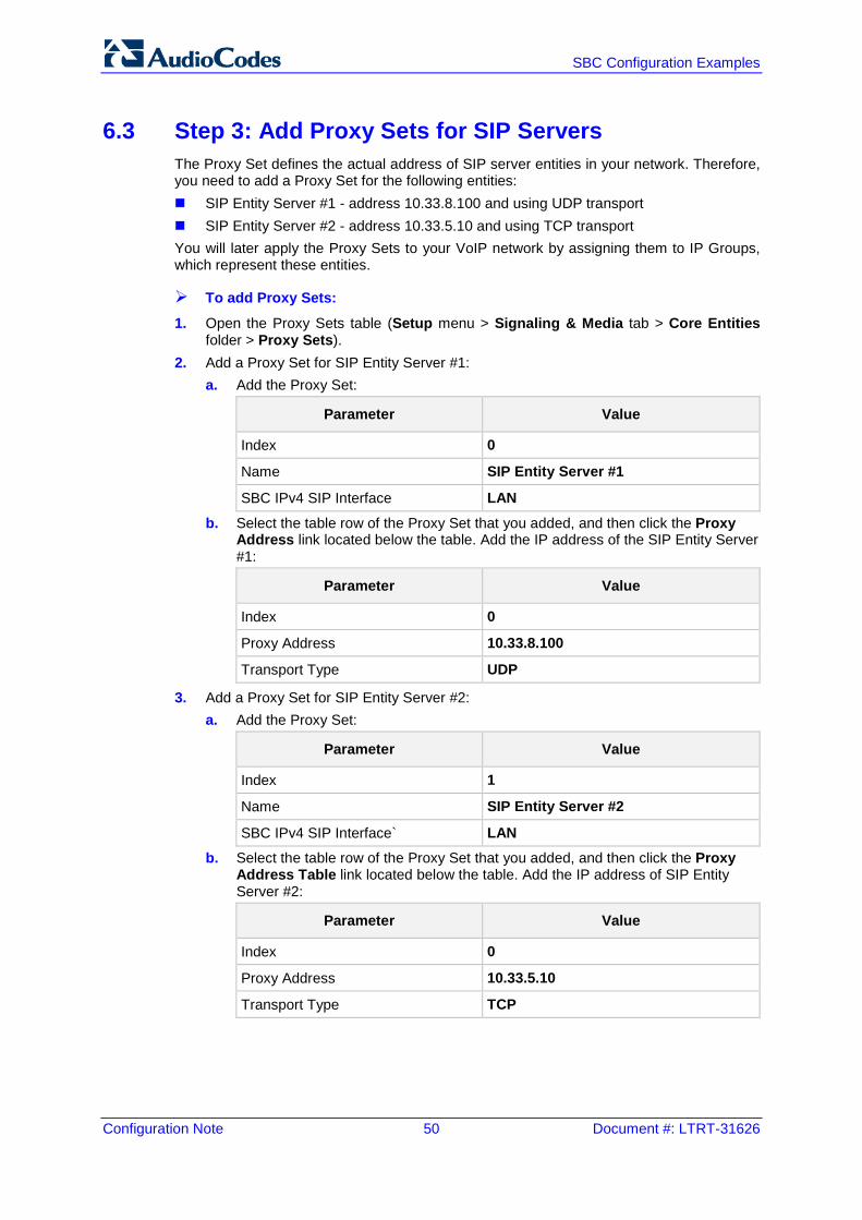
6.3 Step 3: Add Proxy Sets for SIP Servers The Proxy Set defines the actual address of SIP server entities in your network. Therefore, you need to add a Proxy Set for the following entities: SIP Entity Server #1 - address 10.33.8.100 and using UDP transport SIP Entity Server #2 - address 10.33.5.10 and using TCP transport You will later apply the Proxy Sets to your VoIP network by assigning them to IP Groups, which represent these entities.
To add Proxy Sets:
1. Open the Proxy Sets table (Setup menu > Signaling & Media tab > Core Entities folder > Proxy Sets).
2. Add a Proxy Set for SIP Entity Server #1: a. Add the Proxy Set:
Parameter Value
Index 0
Name SIP Entity Server #1
SBC IPv4 SIP Interface LAN
b. Select the table row of the Proxy Set that you added, and then click the Proxy Address link located below the table. Add the IP address of the SIP Entity Server #1:
Parameter Value
Index 0
Proxy Address 10.33.8.100
Transport Type UDP
3. Add a Proxy Set for SIP Entity Server #2: a. Add the Proxy Set:
Parameter Value
Index 1
Name SIP Entity Server #2
SBC IPv4 SIP Interface` LAN b. Select the table row of the Proxy Set that you added, and then click the Proxy
Address Table link located below the table. Add the IP address of SIP Entity Server #2:
Parameter Value
Index 0
Proxy Address 10.33.5.10
Transport Type TCP
Version 7.2 51 Mediant Gateway & SBC Series
Configuration Note 6. SIP Normalization between SIP Entity Servers
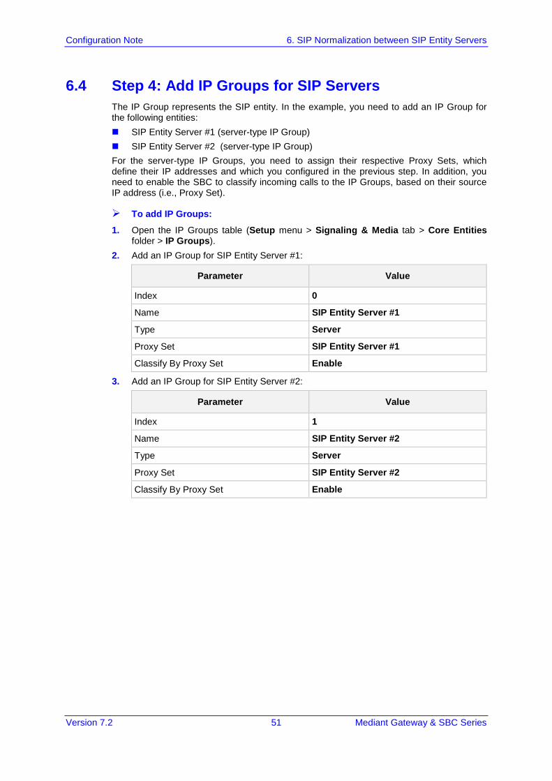
6.4 Step 4: Add IP Groups for SIP Servers The IP Group represents the SIP entity. In the example, you need to add an IP Group for the following entities: SIP Entity Server #1 (server-type IP Group) SIP Entity Server #2 (server-type IP Group) For the server-type IP Groups, you need to assign their respective Proxy Sets, which define their IP addresses and which you configured in the previous step. In addition, you need to enable the SBC to classify incoming calls to the IP Groups, based on their source IP address (i.e., Proxy Set).
To add IP Groups:
1. Open the IP Groups table (Setup menu > Signaling & Media tab > Core Entities folder > IP Groups).
2. Add an IP Group for SIP Entity Server #1:
Parameter Value
Index 0
Name SIP Entity Server #1
Type Server
Proxy Set SIP Entity Server #1
Classify By Proxy Set Enable
3. Add an IP Group for SIP Entity Server #2:
Parameter Value
Index 1
Name SIP Entity Server #2
Type Server
Proxy Set SIP Entity Server #2
Classify By Proxy Set Enable
Configuration Note 52 Document #: LTRT-31626
SBC Configuration Examples
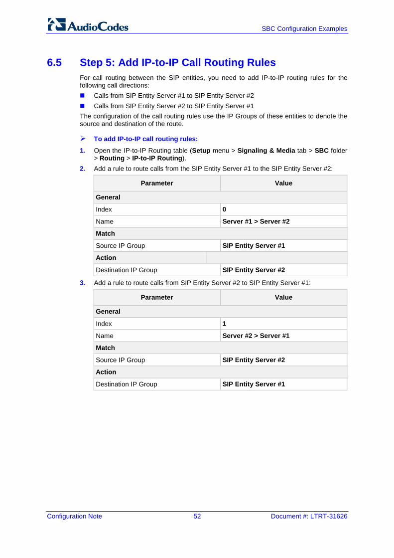
6.5 Step 5: Add IP-to-IP Call Routing Rules For call routing between the SIP entities, you need to add IP-to-IP routing rules for the following call directions: Calls from SIP Entity Server #1 to SIP Entity Server #2 Calls from SIP Entity Server #2 to SIP Entity Server #1 The configuration of the call routing rules use the IP Groups of these entities to denote the source and destination of the route.
To add IP-to-IP call routing rules:
1. Open the IP-to-IP Routing table (Setup menu > Signaling & Media tab > SBC folder > Routing > IP-to-IP Routing).
2. Add a rule to route calls from the SIP Entity Server #1 to the SIP Entity Server #2:
Parameter Value
General
Index 0
Name Server #1 > Server #2
Match
Source IP Group SIP Entity Server #1
Action
Destination IP Group SIP Entity Server #2
3. Add a rule to route calls from SIP Entity Server #2 to SIP Entity Server #1:
Parameter Value
General
Index 1
Name Server #2 > Server #1
Match
Source IP Group SIP Entity Server #2
Action
Destination IP Group SIP Entity Server #1
Version 7.2 53 Mediant Gateway & SBC Series
Configuration Note 6. SIP Normalization between SIP Entity Servers
6.6 Voice Transcoding As the two SIP entity servers use different voice codecs, you need to configure the SBC to perform transcoding between the servers. In the example, the codec support is as follows: SIP Entity Server #1 uses G.711 A-law or G.711 µ-law, and does not allow any other
coder in the SDP offer-exchange coder list SIP Entity Server #2 uses G.729 The configuration for the example uses the following terms related to coders: Extension Coders: Voice codecs supported by the SIP entity. The SBC adds these
coders to the SDP offer sent to the SIP entity. Extension coders are required for transcoding when the two communicating SIP entities support different coders (i.e., supported coders do not appear in the SDP offer).
Allowed Coders: Coders that are permitted to be listed in the SDP offer that the device sends to the SIP entity. This is required for SIP entities that accept only SDPs that include specific coders (for whatever reason). The Allowed coders would include the Extension coder as well as other coders.
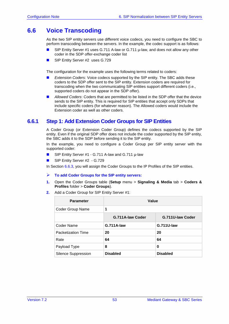
6.6.1 Step 1: Add Extension Coder Groups for SIP Entities A Coder Group (or Extension Coder Group) defines the codecs supported by the SIP entity. Even if the original SDP offer does not include the coder supported by the SIP entity, the SBC adds it to the SDP before sending it to the SIP entity. In the example, you need to configure a Coder Group per SIP entity server with the supported coder: SIP Entity Server #1 - G.711 A-law and G.711 µ-law SIP Entity Server #2 - G.729 In Section 6.6.3, you will assign the Coder Groups to the IP Profiles of the SIP entities.
To add Coder Groups for the SIP entity servers:
1. Open the Coder Groups table (Setup menu > Signaling & Media tab > Coders & Profiles folder > Coder Groups).
2. Add a Coder Group for SIP Entity Server #1:
Parameter Value
Coder Group Name 1
G.711A-law Coder G.711U-law Coder
Coder Name G.711A-law G.711U-law
Packetization Time 20 20
Rate 64 64
Payload Type 8 0
Silence Suppression Disabled Disabled
Configuration Note 54 Document #: LTRT-31626
SBC Configuration Examples
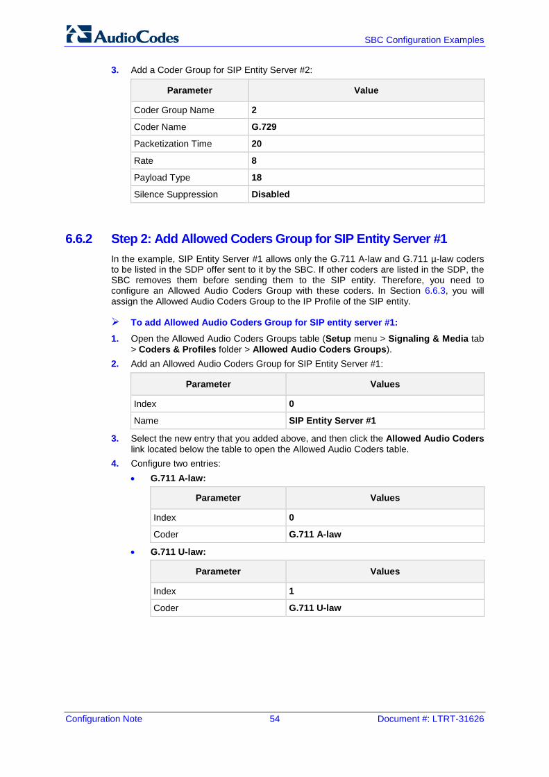
3. Add a Coder Group for SIP Entity Server #2:
Parameter Value
Coder Group Name 2
Coder Name G.729
Packetization Time 20
Rate 8
Payload Type 18
Silence Suppression Disabled
6.6.2 Step 2: Add Allowed Coders Group for SIP Entity Server #1 In the example, SIP Entity Server #1 allows only the G.711 A-law and G.711 µ-law coders to be listed in the SDP offer sent to it by the SBC. If other coders are listed in the SDP, the SBC removes them before sending them to the SIP entity. Therefore, you need to configure an Allowed Audio Coders Group with these coders. In Section 6.6.3, you will assign the Allowed Audio Coders Group to the IP Profile of the SIP entity.
To add Allowed Audio Coders Group for SIP entity server #1:
1. Open the Allowed Audio Coders Groups table (Setup menu > Signaling & Media tab > Coders & Profiles folder > Allowed Audio Coders Groups).
2. Add an Allowed Audio Coders Group for SIP Entity Server #1:
Parameter Values
Index 0
Name SIP Entity Server #1
3. Select the new entry that you added above, and then click the Allowed Audio Coders link located below the table to open the Allowed Audio Coders table.
4. Configure two entries: • G.711 A-law:
Parameter Values
Index 0
Coder G.711 A-law
• G.711 U-law:
Parameter Values
Index 1
Coder G.711 U-law
Version 7.2 55 Mediant Gateway & SBC Series
Configuration Note 6. SIP Normalization between SIP Entity Servers
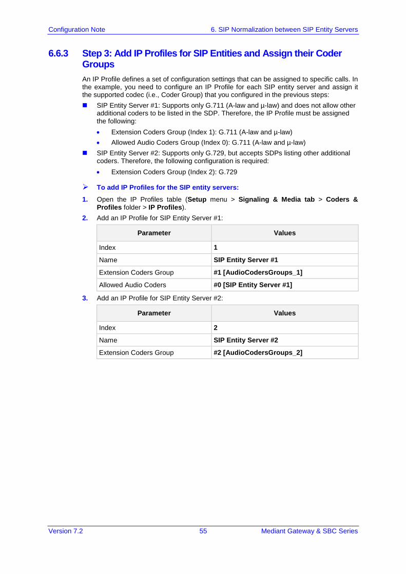
6.6.3 Step 3: Add IP Profiles for SIP Entities and Assign their Coder Groups An IP Profile defines a set of configuration settings that can be assigned to specific calls. In the example, you need to configure an IP Profile for each SIP entity server and assign it the supported codec (i.e., Coder Group) that you configured in the previous steps: SIP Entity Server #1: Supports only G.711 (A-law and µ-law) and does not allow other
additional coders to be listed in the SDP. Therefore, the IP Profile must be assigned the following: • Extension Coders Group (Index 1): G.711 (A-law and µ-law) • Allowed Audio Coders Group (Index 0): G.711 (A-law and µ-law)
SIP Entity Server #2: Supports only G.729, but accepts SDPs listing other additional coders. Therefore, the following configuration is required: • Extension Coders Group (Index 2): G.729
To add IP Profiles for the SIP entity servers:
1. Open the IP Profiles table (Setup menu > Signaling & Media tab > Coders & Profiles folder > IP Profiles).
2. Add an IP Profile for SIP Entity Server #1:
Parameter Values
Index 1
Name SIP Entity Server #1
Extension Coders Group #1 [AudioCodersGroups_1]
Allowed Audio Coders #0 [SIP Entity Server #1]
3. Add an IP Profile for SIP Entity Server #2:
Parameter Values
Index 2
Name SIP Entity Server #2
Extension Coders Group #2 [AudioCodersGroups_2]
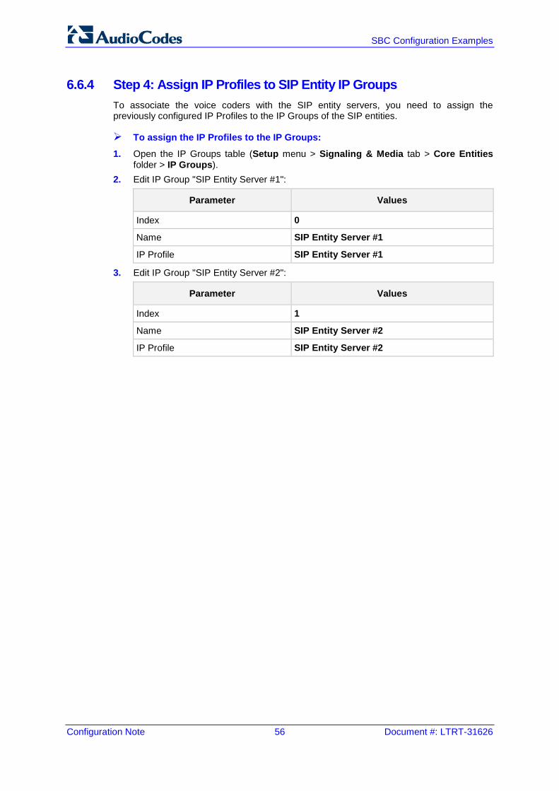
Configuration Note 56 Document #: LTRT-31626
SBC Configuration Examples
6.6.4 Step 4: Assign IP Profiles to SIP Entity IP Groups To associate the voice coders with the SIP entity servers, you need to assign the previously configured IP Profiles to the IP Groups of the SIP entities.
To assign the IP Profiles to the IP Groups:
1. Open the IP Groups table (Setup menu > Signaling & Media tab > Core Entities folder > IP Groups).
2. Edit IP Group "SIP Entity Server #1":
Parameter Values
Index 0
Name SIP Entity Server #1
IP Profile SIP Entity Server #1
3. Edit IP Group "SIP Entity Server #2":
Parameter Values
Index 1
Name SIP Entity Server #2
IP Profile SIP Entity Server #2
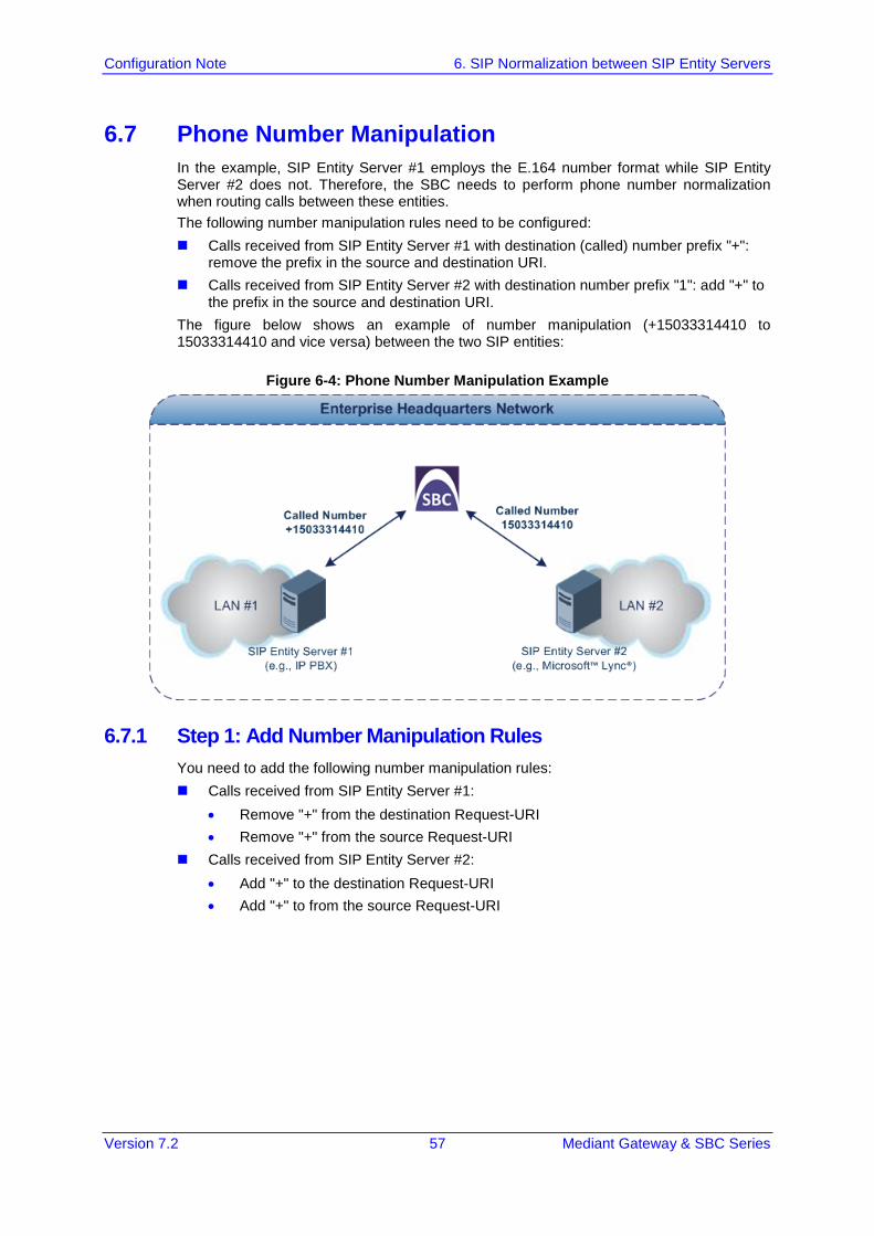
Version 7.2 57 Mediant Gateway & SBC Series
Configuration Note 6. SIP Normalization between SIP Entity Servers
6.7 Phone Number Manipulation In the example, SIP Entity Server #1 employs the E.164 number format while SIP Entity Server #2 does not. Therefore, the SBC needs to perform phone number normalization when routing calls between these entities. The following number manipulation rules need to be configured: Calls received from SIP Entity Server #1 with destination (called) number prefix "+":
remove the prefix in the source and destination URI. Calls received from SIP Entity Server #2 with destination number prefix "1": add "+" to
the prefix in the source and destination URI. The figure below shows an example of number manipulation (+15033314410 to 15033314410 and vice versa) between the two SIP entities:
Figure 6-4: Phone Number Manipulation Example
6.7.1 Step 1: Add Number Manipulation Rules You need to add the following number manipulation rules: Calls received from SIP Entity Server #1:
• Remove "+" from the destination Request-URI • Remove "+" from the source Request-URI
Calls received from SIP Entity Server #2: • Add "+" to the destination Request-URI • Add "+" to from the source Request-URI
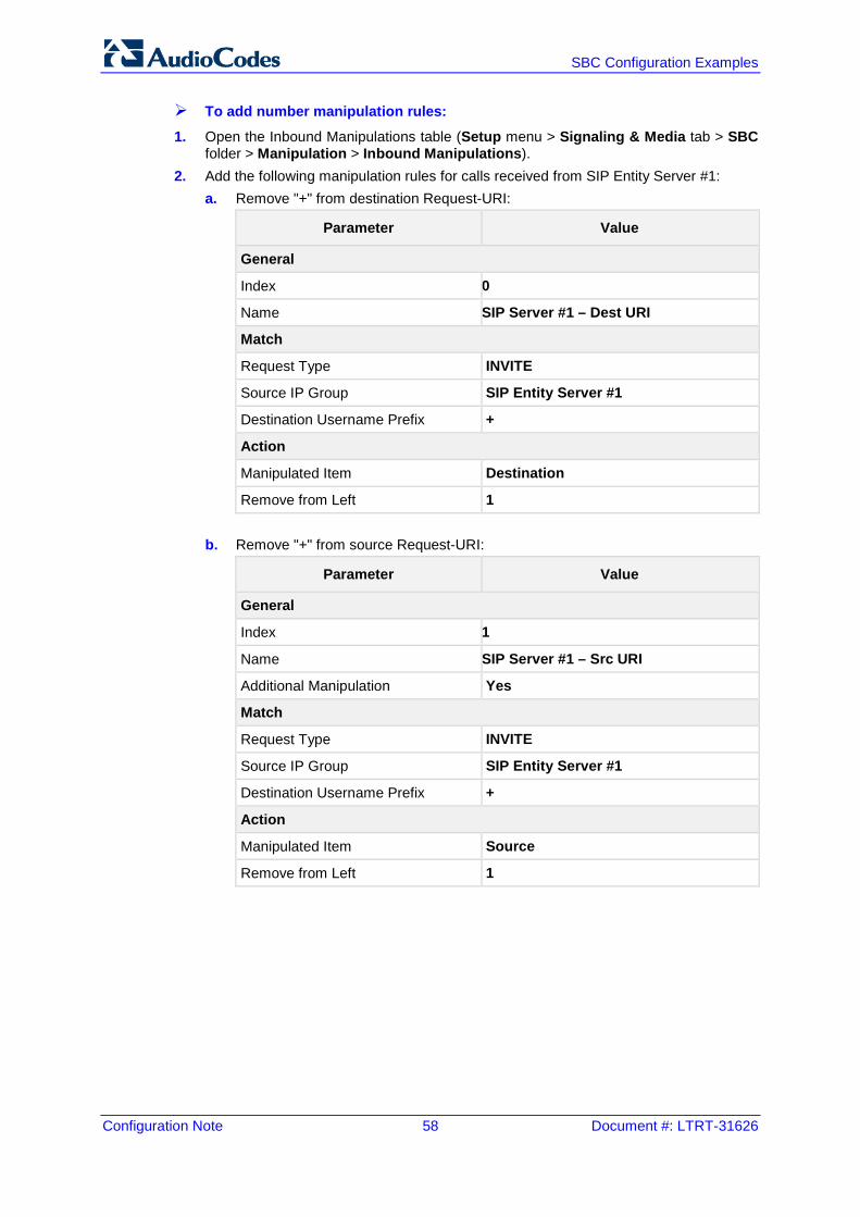
Configuration Note 58 Document #: LTRT-31626
SBC Configuration Examples
To add number manipulation rules:
1. Open the Inbound Manipulations table (Setup menu > Signaling & Media tab > SBC folder > Manipulation > Inbound Manipulations).
2. Add the following manipulation rules for calls received from SIP Entity Server #1: a. Remove "+" from destination Request-URI:
Parameter Value
General
Index 0
Name SIP Server #1 – Dest URI
Match
Request Type INVITE
Source IP Group SIP Entity Server #1
Destination Username Prefix +
Action
Manipulated Item Destination
Remove from Left 1
b. Remove "+" from source Request-URI:
Parameter Value
General
Index 1
Name SIP Server #1 – Src URI
Additional Manipulation Yes
Match
Request Type INVITE
Source IP Group SIP Entity Server #1
Destination Username Prefix +
Action
Manipulated Item Source
Remove from Left 1
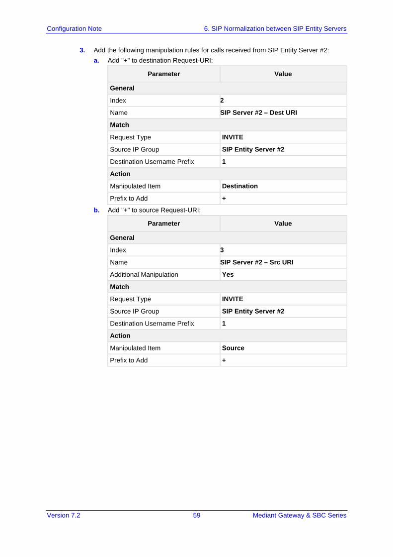
Version 7.2 59 Mediant Gateway & SBC Series
Configuration Note 6. SIP Normalization between SIP Entity Servers
3. Add the following manipulation rules for calls received from SIP Entity Server #2: a. Add "+" to destination Request-URI:
Parameter Value
General
Index 2
Name SIP Server #2 – Dest URI
Match
Request Type INVITE
Source IP Group SIP Entity Server #2
Destination Username Prefix 1
Action
Manipulated Item Destination
Prefix to Add +
b. Add "+" to source Request-URI:
Parameter Value
General
Index 3
Name SIP Server #2 – Src URI
Additional Manipulation Yes
Match
Request Type INVITE
Source IP Group SIP Entity Server #2
Destination Username Prefix 1
Action
Manipulated Item Source
Prefix to Add +
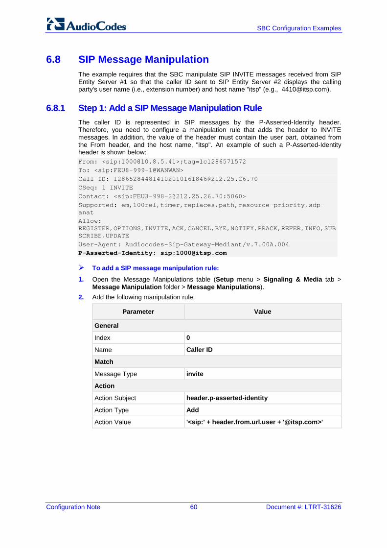
Configuration Note 60 Document #: LTRT-31626
SBC Configuration Examples
6.8 SIP Message Manipulation The example requires that the SBC manipulate SIP INVITE messages received from SIP Entity Server #1 so that the caller ID sent to SIP Entity Server #2 displays the calling party's user name (i.e., extension number) and host name "itsp" (e.g., [email protected]).
6.8.1 Step 1: Add a SIP Message Manipulation Rule The caller ID is represented in SIP messages by the P-Asserted-Identity header. Therefore, you need to configure a manipulation rule that adds the header to INVITE messages. In addition, the value of the header must contain the user part, obtained from the From header, and the host name, "itsp". An example of such a P-Asserted-Identity header is shown below: From: <sip:[email protected]>;tag=1c1286571572 To: <sip:FEU8-999-1@WANWAN> Call-ID: [email protected] CSeq: 1 INVITE Contact: <sip:[email protected]:5060> Supported: em,100rel,timer,replaces,path,resource-priority,sdp-anat Allow: REGISTER,OPTIONS,INVITE,ACK,CANCEL,BYE,NOTIFY,PRACK,REFER,INFO,SUBSCRIBE,UPDATE User-Agent: Audiocodes-Sip-Gateway-Mediant/v.7.00A.004 P-Asserted-Identity: sip:[email protected]
To add a SIP message manipulation rule:
1. Open the Message Manipulations table (Setup menu > Signaling & Media tab > Message Manipulation folder > Message Manipulations).
2. Add the following manipulation rule:
Parameter Value
General
Index 0
Name Caller ID
Match
Message Type invite
Action
Action Subject header.p-asserted-identity
Action Type Add
Action Value '<sip:' + header.from.url.user + '@itsp.com>'
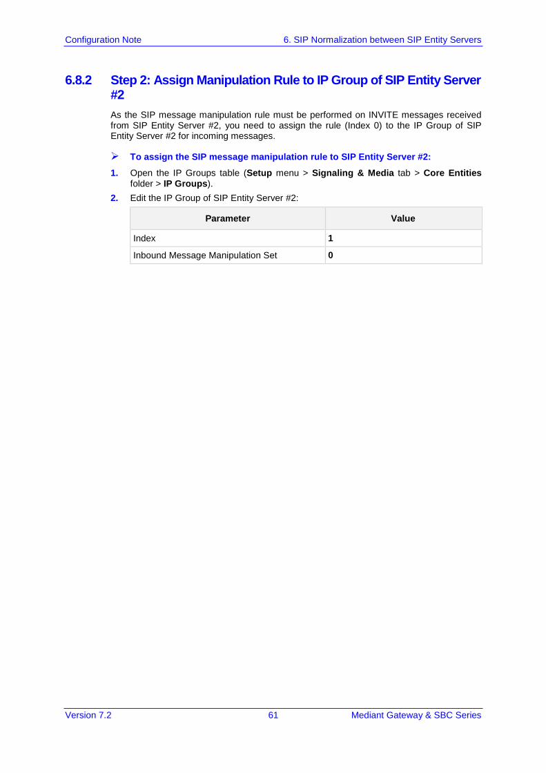
Version 7.2 61 Mediant Gateway & SBC Series
Configuration Note 6. SIP Normalization between SIP Entity Servers
6.8.2 Step 2: Assign Manipulation Rule to IP Group of SIP Entity Server #2 As the SIP message manipulation rule must be performed on INVITE messages received from SIP Entity Server #2, you need to assign the rule (Index 0) to the IP Group of SIP Entity Server #2 for incoming messages.
To assign the SIP message manipulation rule to SIP Entity Server #2:
1. Open the IP Groups table (Setup menu > Signaling & Media tab > Core Entities folder > IP Groups).
2. Edit the IP Group of SIP Entity Server #2:
Parameter Value
Index 1
Inbound Message Manipulation Set 0

Configuration Note 62 Document #: LTRT-31626
SBC Configuration Examples
This page is intentionally left blank.
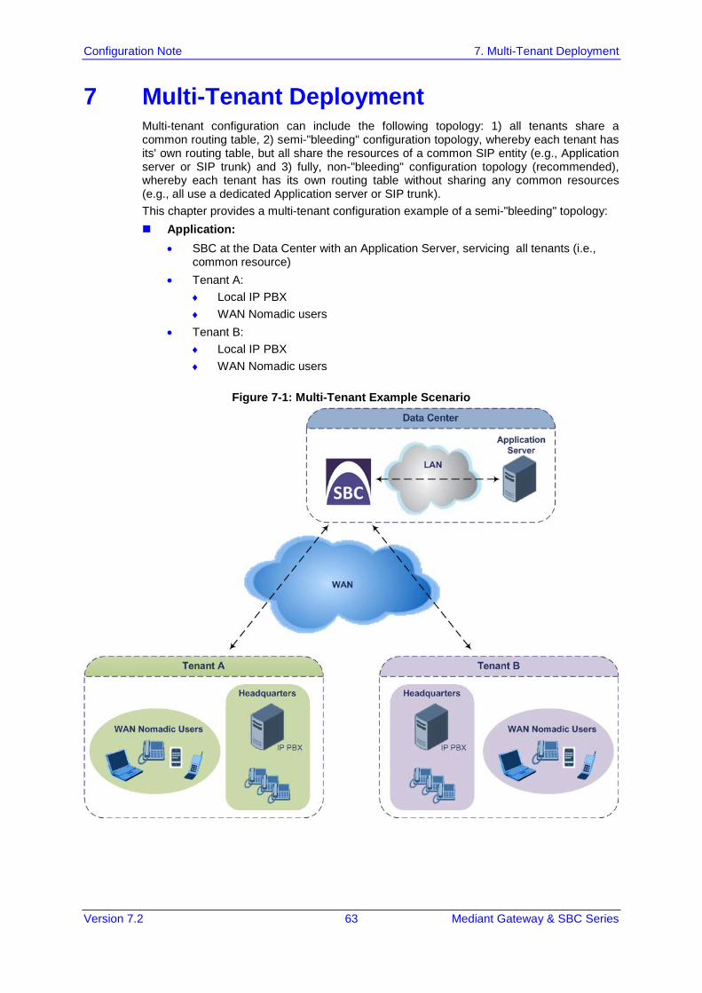
Version 7.2 63 Mediant Gateway & SBC Series
Configuration Note 7. Multi-Tenant Deployment
7 Multi-Tenant Deployment Multi-tenant configuration can include the following topology: 1) all tenants share a common routing table, 2) semi-"bleeding" configuration topology, whereby each tenant has its' own routing table, but all share the resources of a common SIP entity (e.g., Application server or SIP trunk) and 3) fully, non-"bleeding" configuration topology (recommended), whereby each tenant has its own routing table without sharing any common resources (e.g., all use a dedicated Application server or SIP trunk). This chapter provides a multi-tenant configuration example of a semi-"bleeding" topology: Application:
• SBC at the Data Center with an Application Server, servicing all tenants (i.e., common resource)
• Tenant A: ♦ Local IP PBX ♦ WAN Nomadic users
• Tenant B: ♦ Local IP PBX ♦ WAN Nomadic users
Figure 7-1: Multi-Tenant Example Scenario
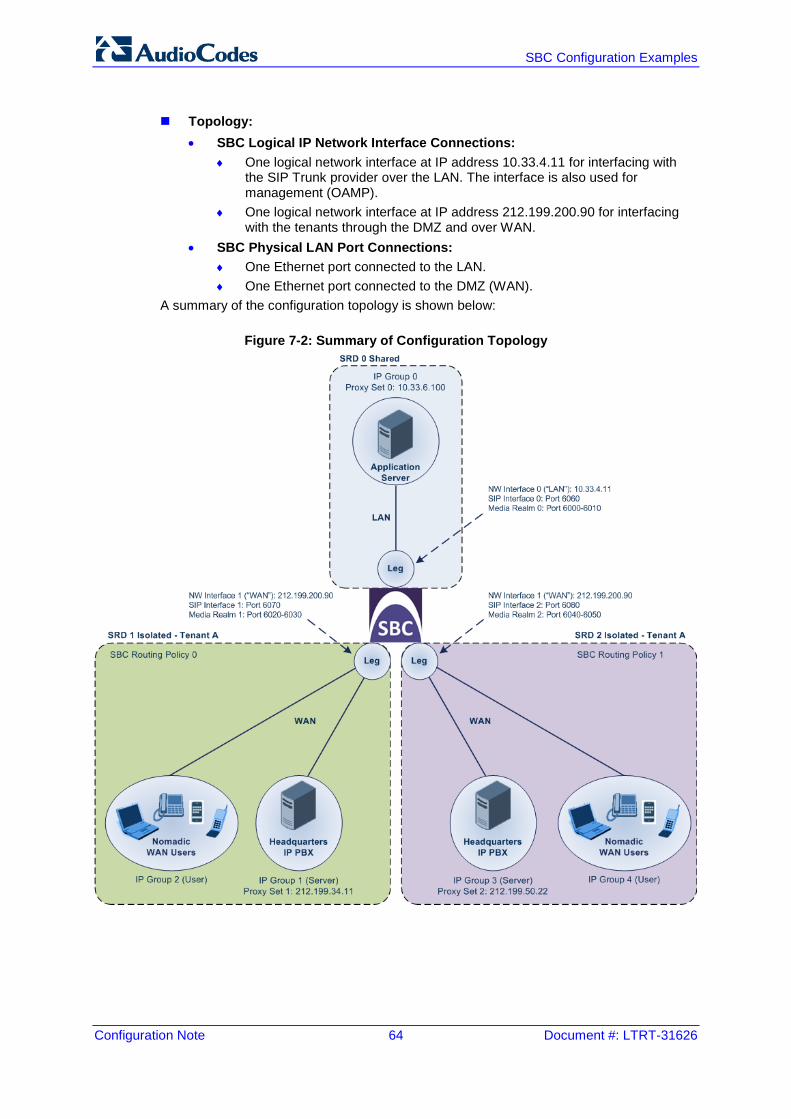
Configuration Note 64 Document #: LTRT-31626
SBC Configuration Examples
Topology:
• SBC Logical IP Network Interface Connections: ♦ One logical network interface at IP address 10.33.4.11 for interfacing with
the SIP Trunk provider over the LAN. The interface is also used for management (OAMP).
♦ One logical network interface at IP address 212.199.200.90 for interfacing with the tenants through the DMZ and over WAN.
• SBC Physical LAN Port Connections: ♦ One Ethernet port connected to the LAN. ♦ One Ethernet port connected to the DMZ (WAN).
A summary of the configuration topology is shown below:
Figure 7-2: Summary of Configuration Topology
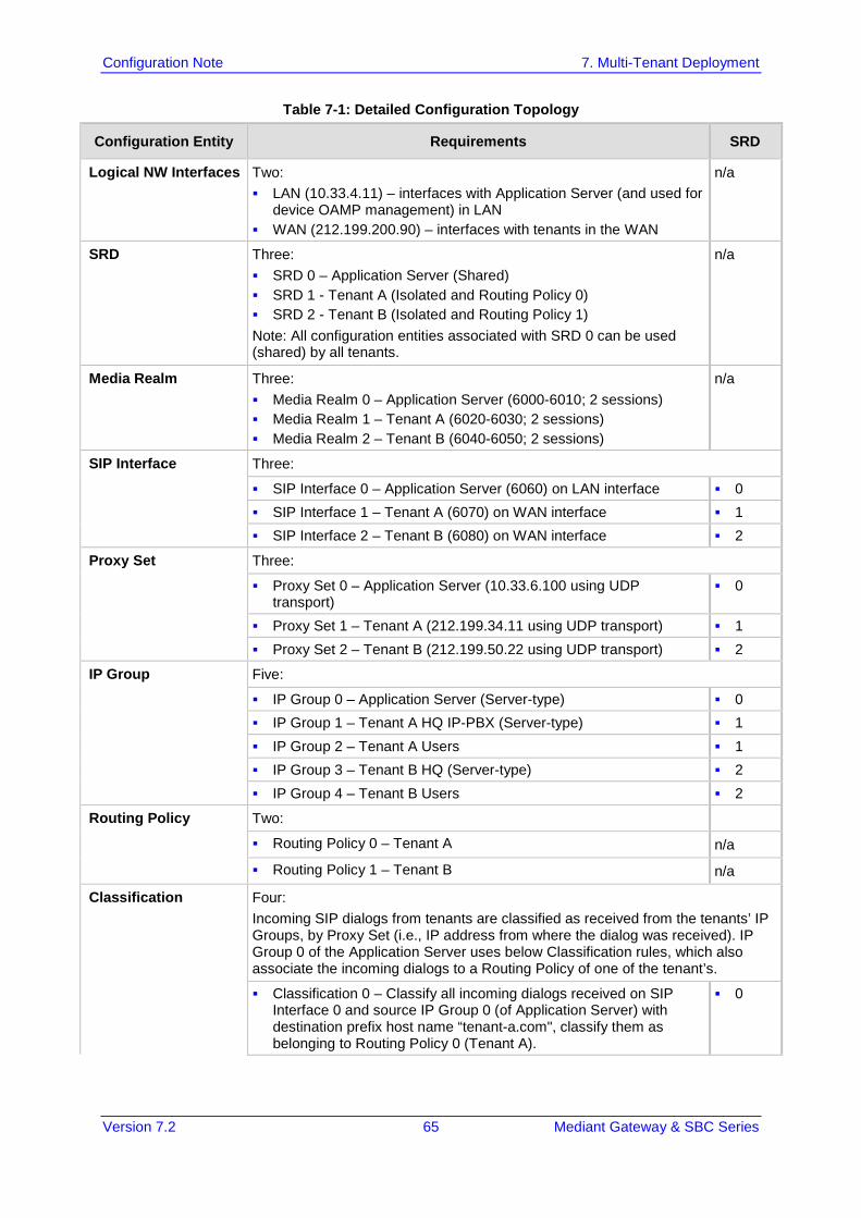
Version 7.2 65 Mediant Gateway & SBC Series
Configuration Note 7. Multi-Tenant Deployment
Table 7-1: Detailed Configuration Topology
Configuration Entity Requirements SRD
Logical NW Interfaces Two: LAN (10.33.4.11) – interfaces with Application Server (and used for
device OAMP management) in LAN WAN (212.199.200.90) – interfaces with tenants in the WAN
n/a
SRD Three: SRD 0 – Application Server (Shared) SRD 1 - Tenant A (Isolated and Routing Policy 0) SRD 2 - Tenant B (Isolated and Routing Policy 1) Note: All configuration entities associated with SRD 0 can be used (shared) by all tenants.
n/a
Media Realm Three: Media Realm 0 – Application Server (6000-6010; 2 sessions) Media Realm 1 – Tenant A (6020-6030; 2 sessions) Media Realm 2 – Tenant B (6040-6050; 2 sessions)
n/a
SIP Interface Three:
SIP Interface 0 – Application Server (6060) on LAN interface 0 SIP Interface 1 – Tenant A (6070) on WAN interface 1 SIP Interface 2 – Tenant B (6080) on WAN interface 2
Proxy Set Three:
Proxy Set 0 – Application Server (10.33.6.100 using UDP transport)
0
Proxy Set 1 – Tenant A (212.199.34.11 using UDP transport) 1 Proxy Set 2 – Tenant B (212.199.50.22 using UDP transport) 2
IP Group Five:
IP Group 0 – Application Server (Server-type) 0 IP Group 1 – Tenant A HQ IP-PBX (Server-type) 1 IP Group 2 – Tenant A Users 1 IP Group 3 – Tenant B HQ (Server-type) 2 IP Group 4 – Tenant B Users 2
Routing Policy Two:
Routing Policy 0 – Tenant A n/a
Routing Policy 1 – Tenant B n/a
Classification Four: Incoming SIP dialogs from tenants are classified as received from the tenants’ IP Groups, by Proxy Set (i.e., IP address from where the dialog was received). IP Group 0 of the Application Server uses below Classification rules, which also associate the incoming dialogs to a Routing Policy of one of the tenant’s.
Classification 0 – Classify all incoming dialogs received on SIP Interface 0 and source IP Group 0 (of Application Server) with destination prefix host name “tenant-a.com", classify them as belonging to Routing Policy 0 (Tenant A).
0
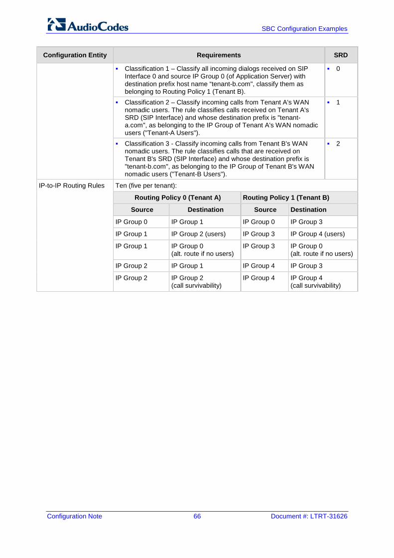
Configuration Note 66 Document #: LTRT-31626
SBC Configuration Examples
Configuration Entity Requirements SRD
Classification 1 – Classify all incoming dialogs received on SIP Interface 0 and source IP Group 0 (of Application Server) with destination prefix host name “tenant-b.com", classify them as belonging to Routing Policy 1 (Tenant B).
0
Classification 2 – Classify incoming calls from Tenant A's WAN nomadic users. The rule classifies calls received on Tenant A's SRD (SIP Interface) and whose destination prefix is "tenant-a.com", as belonging to the IP Group of Tenant A's WAN nomadic users ("Tenant-A Users").
1
Classification 3 - Classify incoming calls from Tenant B's WAN nomadic users. The rule classifies calls that are received on Tenant B's SRD (SIP Interface) and whose destination prefix is "tenant-b.com", as belonging to the IP Group of Tenant B's WAN nomadic users ("Tenant-B Users").
2
IP-to-IP Routing Rules Ten (five per tenant):
Routing Policy 0 (Tenant A) Routing Policy 1 (Tenant B)
Source Destination Source Destination
IP Group 0 IP Group 1 IP Group 0 IP Group 3
IP Group 1 IP Group 2 (users) IP Group 3 IP Group 4 (users)
IP Group 1 IP Group 0 (alt. route if no users)
IP Group 3 IP Group 0 (alt. route if no users)
IP Group 2 IP Group 1 IP Group 4 IP Group 3
IP Group 2 IP Group 2 (call survivability)
IP Group 4 IP Group 4 (call survivability)
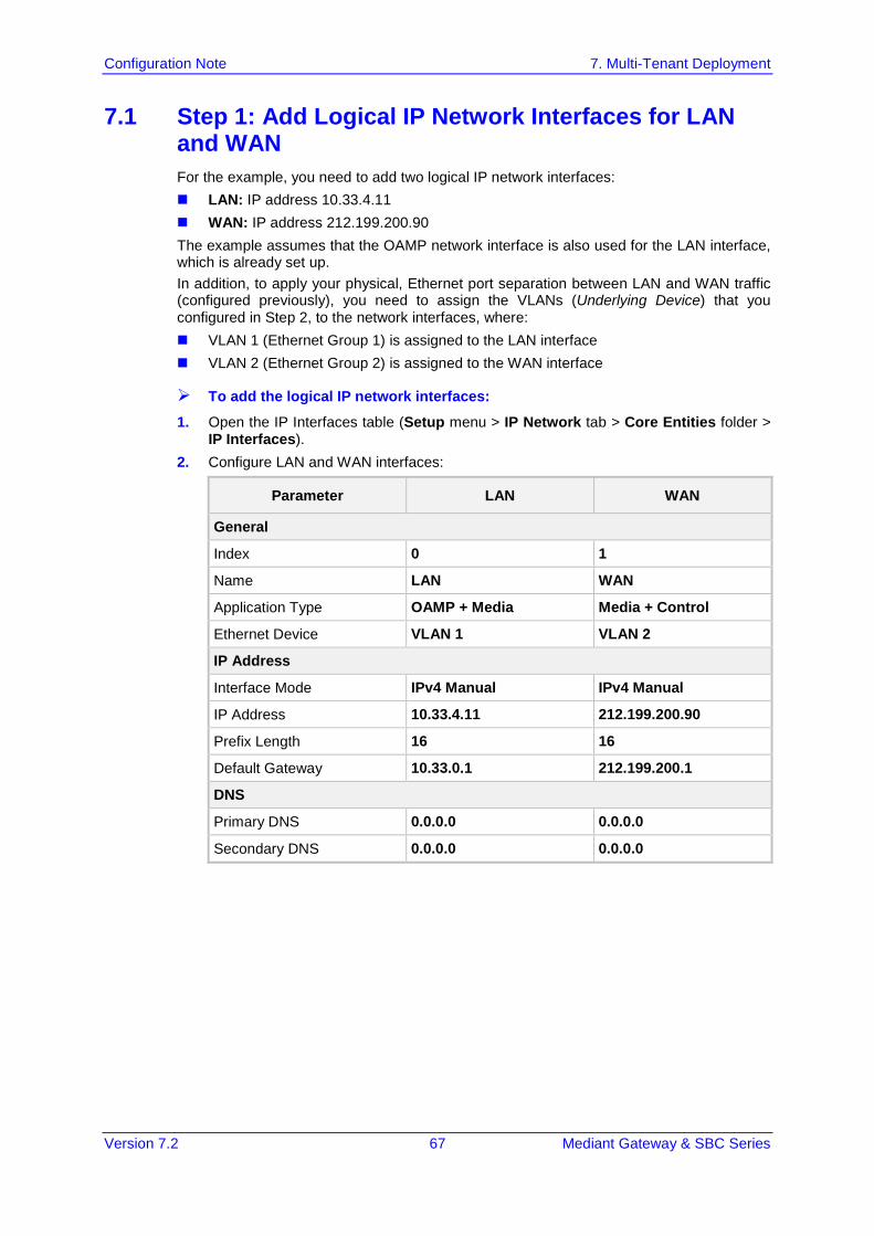
Version 7.2 67 Mediant Gateway & SBC Series
Configuration Note 7. Multi-Tenant Deployment
7.1 Step 1: Add Logical IP Network Interfaces for LAN and WAN For the example, you need to add two logical IP network interfaces: LAN: IP address 10.33.4.11 WAN: IP address 212.199.200.90 The example assumes that the OAMP network interface is also used for the LAN interface, which is already set up. In addition, to apply your physical, Ethernet port separation between LAN and WAN traffic (configured previously), you need to assign the VLANs (Underlying Device) that you configured in Step 2, to the network interfaces, where: VLAN 1 (Ethernet Group 1) is assigned to the LAN interface VLAN 2 (Ethernet Group 2) is assigned to the WAN interface
To add the logical IP network interfaces:
1. Open the IP Interfaces table (Setup menu > IP Network tab > Core Entities folder > IP Interfaces).
2. Configure LAN and WAN interfaces:
Parameter LAN WAN
General
Index 0 1
Name LAN WAN
Application Type OAMP + Media Media + Control
Ethernet Device VLAN 1 VLAN 2
IP Address
Interface Mode IPv4 Manual IPv4 Manual
IP Address 10.33.4.11 212.199.200.90
Prefix Length 16 16
Default Gateway 10.33.0.1 212.199.200.1
DNS
Primary DNS 0.0.0.0 0.0.0.0
Secondary DNS 0.0.0.0 0.0.0.0
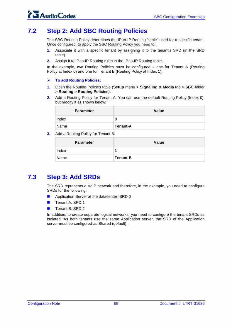
Configuration Note 68 Document #: LTRT-31626
SBC Configuration Examples
7.2 Step 2: Add SBC Routing Policies The SBC Routing Policy determines the IP-to-IP Routing "table" used for a specific tenant. Once configured, to apply the SBC Routing Policy you need to: 1. Associate it with a specific tenant by assigning it to the tenant’s SRD (in the SRD
table). 2. Assign it to IP-to-IP Routing rules in the IP-to-IP Routing table. In the example, two Routing Policies must be configured – one for Tenant A (Routing Policy at Index 0) and one for Tenant B (Routing Policy at Index 1).
To add Routing Policies:
1. Open the Routing Policies table (Setup menu > Signaling & Media tab > SBC folder > Routing > Routing Policies).
2. Add a Routing Policy for Tenant A. You can use the default Routing Policy (Index 0), but modify it as shown below:
Parameter Value
Index 0
Name Tenant-A
3. Add a Routing Policy for Tenant B:
Parameter Value
Index 1
Name Tenant-B
7.3 Step 3: Add SRDs The SRD represents a VoIP network and therefore, in the example, you need to configure SRDs for the following: Application Server at the datacenter: SRD 0 Tenant A: SRD 1 Tenant B: SRD 2 In addition, to create separate logical networks, you need to configure the tenant SRDs as Isolated. As both tenants use the same Application server, the SRD of the Application server must be configured as Shared (default).
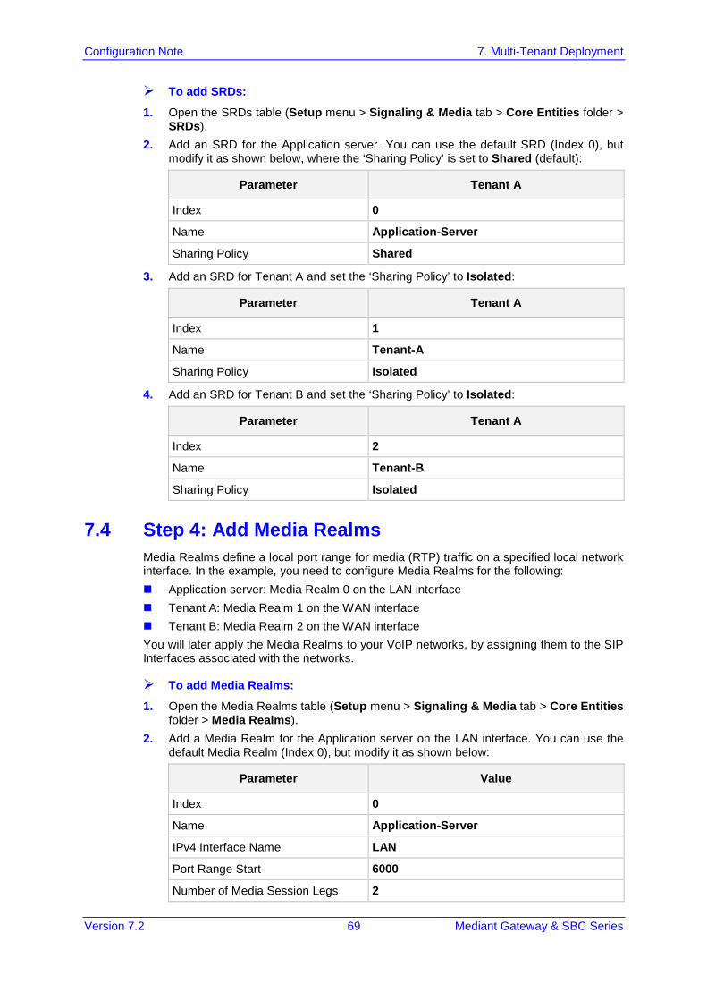
Version 7.2 69 Mediant Gateway & SBC Series
Configuration Note 7. Multi-Tenant Deployment
To add SRDs:
1. Open the SRDs table (Setup menu > Signaling & Media tab > Core Entities folder > SRDs).
2. Add an SRD for the Application server. You can use the default SRD (Index 0), but modify it as shown below, where the ‘Sharing Policy’ is set to Shared (default):
Parameter Tenant A
Index 0
Name Application-Server
Sharing Policy Shared
3. Add an SRD for Tenant A and set the ‘Sharing Policy’ to Isolated:
Parameter Tenant A
Index 1
Name Tenant-A
Sharing Policy Isolated
4. Add an SRD for Tenant B and set the ‘Sharing Policy’ to Isolated:
Parameter Tenant A
Index 2
Name Tenant-B
Sharing Policy Isolated
7.4 Step 4: Add Media Realms Media Realms define a local port range for media (RTP) traffic on a specified local network interface. In the example, you need to configure Media Realms for the following: Application server: Media Realm 0 on the LAN interface Tenant A: Media Realm 1 on the WAN interface Tenant B: Media Realm 2 on the WAN interface You will later apply the Media Realms to your VoIP networks, by assigning them to the SIP Interfaces associated with the networks.
To add Media Realms:
1. Open the Media Realms table (Setup menu > Signaling & Media tab > Core Entities folder > Media Realms).
2. Add a Media Realm for the Application server on the LAN interface. You can use the default Media Realm (Index 0), but modify it as shown below:
Parameter Value
Index 0
Name Application-Server
IPv4 Interface Name LAN
Port Range Start 6000
Number of Media Session Legs 2
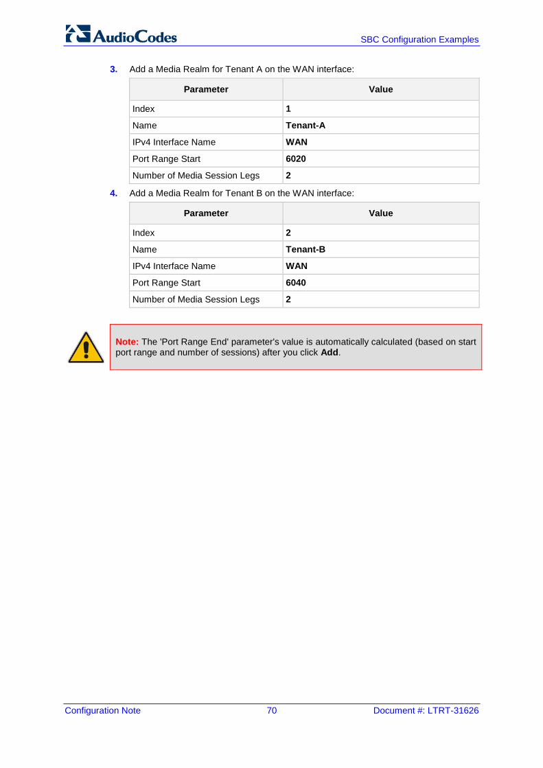
Configuration Note 70 Document #: LTRT-31626
SBC Configuration Examples
3. Add a Media Realm for Tenant A on the WAN interface:
Parameter Value
Index 1
Name Tenant-A
IPv4 Interface Name WAN
Port Range Start 6020
Number of Media Session Legs 2
4. Add a Media Realm for Tenant B on the WAN interface:
Parameter Value
Index 2
Name Tenant-B
IPv4 Interface Name WAN
Port Range Start 6040
Number of Media Session Legs 2
Note: The 'Port Range End' parameter's value is automatically calculated (based on start port range and number of sessions) after you click Add.
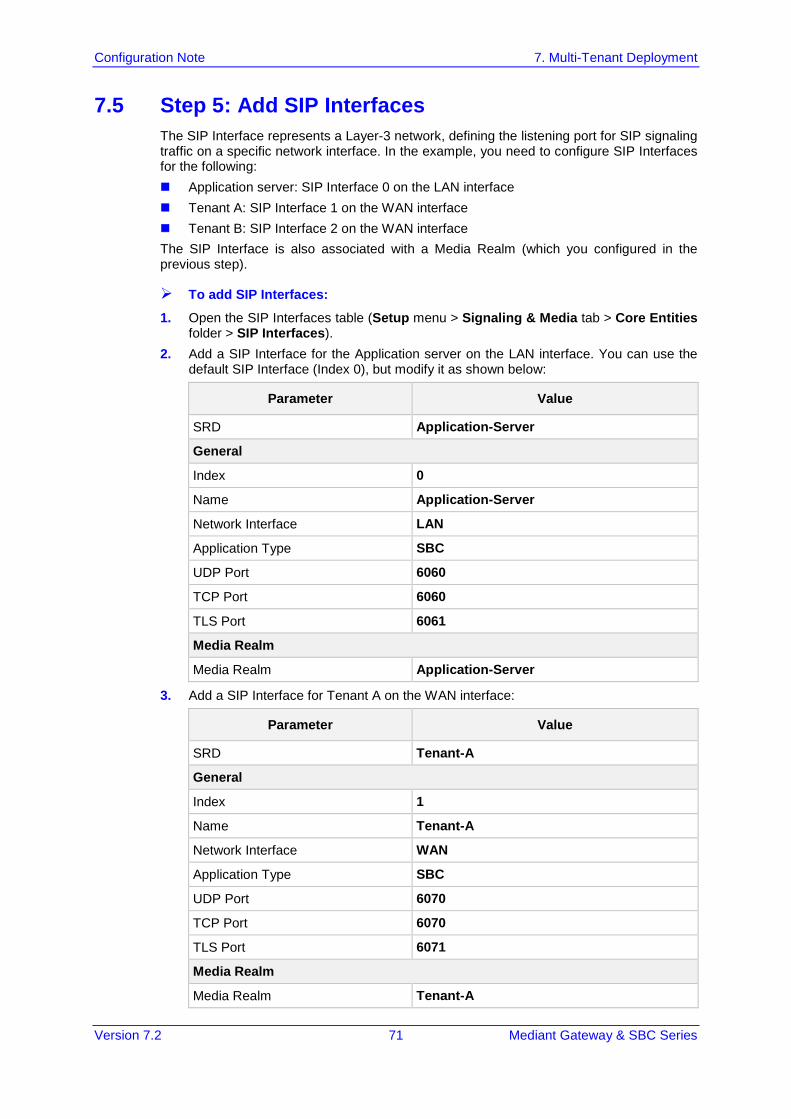
Version 7.2 71 Mediant Gateway & SBC Series
Configuration Note 7. Multi-Tenant Deployment
7.5 Step 5: Add SIP Interfaces The SIP Interface represents a Layer-3 network, defining the listening port for SIP signaling traffic on a specific network interface. In the example, you need to configure SIP Interfaces for the following: Application server: SIP Interface 0 on the LAN interface Tenant A: SIP Interface 1 on the WAN interface Tenant B: SIP Interface 2 on the WAN interface The SIP Interface is also associated with a Media Realm (which you configured in the previous step).
To add SIP Interfaces:
1. Open the SIP Interfaces table (Setup menu > Signaling & Media tab > Core Entities folder > SIP Interfaces).
2. Add a SIP Interface for the Application server on the LAN interface. You can use the default SIP Interface (Index 0), but modify it as shown below:
Parameter Value
SRD Application-Server
General
Index 0
Name Application-Server
Network Interface LAN
Application Type SBC
UDP Port 6060
TCP Port 6060
TLS Port 6061
Media Realm
Media Realm Application-Server
3. Add a SIP Interface for Tenant A on the WAN interface:
Parameter Value
SRD Tenant-A
General
Index 1
Name Tenant-A
Network Interface WAN
Application Type SBC
UDP Port 6070
TCP Port 6070
TLS Port 6071
Media Realm
Media Realm Tenant-A
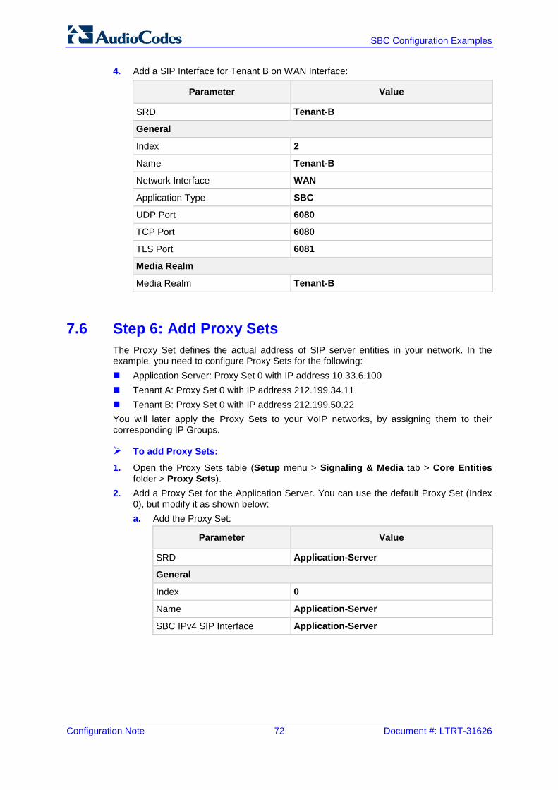
Configuration Note 72 Document #: LTRT-31626
SBC Configuration Examples
4. Add a SIP Interface for Tenant B on WAN Interface:
Parameter Value
SRD Tenant-B
General
Index 2
Name Tenant-B
Network Interface WAN
Application Type SBC
UDP Port 6080
TCP Port 6080
TLS Port 6081
Media Realm
Media Realm Tenant-B
7.6 Step 6: Add Proxy Sets The Proxy Set defines the actual address of SIP server entities in your network. In the example, you need to configure Proxy Sets for the following: Application Server: Proxy Set 0 with IP address 10.33.6.100 Tenant A: Proxy Set 0 with IP address 212.199.34.11 Tenant B: Proxy Set 0 with IP address 212.199.50.22 You will later apply the Proxy Sets to your VoIP networks, by assigning them to their corresponding IP Groups.
To add Proxy Sets:
1. Open the Proxy Sets table (Setup menu > Signaling & Media tab > Core Entities folder > Proxy Sets).
2. Add a Proxy Set for the Application Server. You can use the default Proxy Set (Index 0), but modify it as shown below: a. Add the Proxy Set:
Parameter Value
SRD Application-Server
General
Index 0
Name Application-Server
SBC IPv4 SIP Interface Application-Server
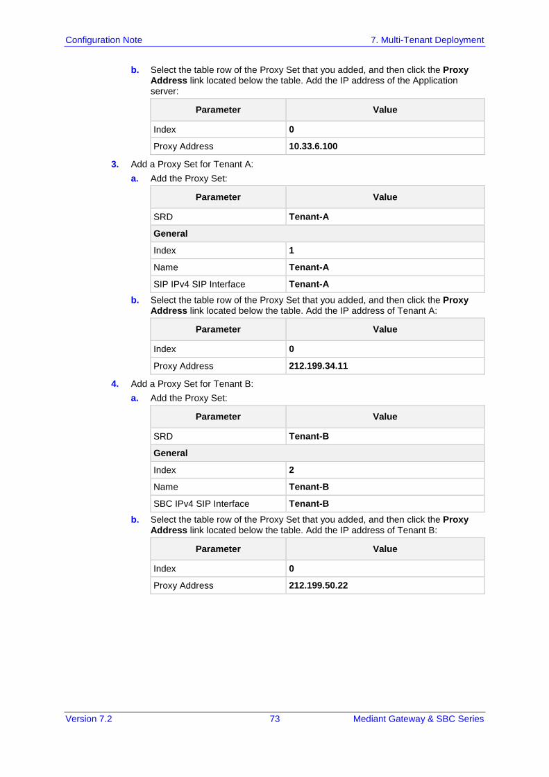
Version 7.2 73 Mediant Gateway & SBC Series
Configuration Note 7. Multi-Tenant Deployment
b. Select the table row of the Proxy Set that you added, and then click the Proxy Address link located below the table. Add the IP address of the Application server:
Parameter Value
Index 0
Proxy Address 10.33.6.100
3. Add a Proxy Set for Tenant A: a. Add the Proxy Set:
Parameter Value
SRD Tenant-A
General
Index 1
Name Tenant-A
SIP IPv4 SIP Interface Tenant-A b. Select the table row of the Proxy Set that you added, and then click the Proxy
Address link located below the table. Add the IP address of Tenant A:
Parameter Value
Index 0
Proxy Address 212.199.34.11
4. Add a Proxy Set for Tenant B: a. Add the Proxy Set:
Parameter Value
SRD Tenant-B
General
Index 2
Name Tenant-B
SBC IPv4 SIP Interface Tenant-B b. Select the table row of the Proxy Set that you added, and then click the Proxy
Address link located below the table. Add the IP address of Tenant B:
Parameter Value
Index 0
Proxy Address 212.199.50.22
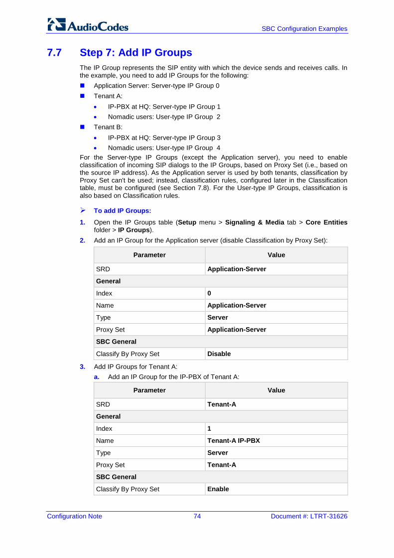
Configuration Note 74 Document #: LTRT-31626
SBC Configuration Examples
7.7 Step 7: Add IP Groups The IP Group represents the SIP entity with which the device sends and receives calls. In the example, you need to add IP Groups for the following: Application Server: Server-type IP Group 0 Tenant A:
• IP-PBX at HQ: Server-type IP Group 1 • Nomadic users: User-type IP Group 2
Tenant B: • IP-PBX at HQ: Server-type IP Group 3 • Nomadic users: User-type IP Group 4
For the Server-type IP Groups (except the Application server), you need to enable classification of incoming SIP dialogs to the IP Groups, based on Proxy Set (i.e., based on the source IP address). As the Application server is used by both tenants, classification by Proxy Set can't be used; instead, classification rules, configured later in the Classification table, must be configured (see Section 7.8). For the User-type IP Groups, classification is also based on Classification rules.
To add IP Groups:
1. Open the IP Groups table (Setup menu > Signaling & Media tab > Core Entities folder > IP Groups).
2. Add an IP Group for the Application server (disable Classification by Proxy Set):
Parameter Value
SRD Application-Server
General
Index 0
Name Application-Server
Type Server
Proxy Set Application-Server
SBC General
Classify By Proxy Set Disable
3. Add IP Groups for Tenant A: a. Add an IP Group for the IP-PBX of Tenant A:
Parameter Value
SRD Tenant-A
General
Index 1
Name Tenant-A IP-PBX
Type Server
Proxy Set Tenant-A
SBC General
Classify By Proxy Set Enable
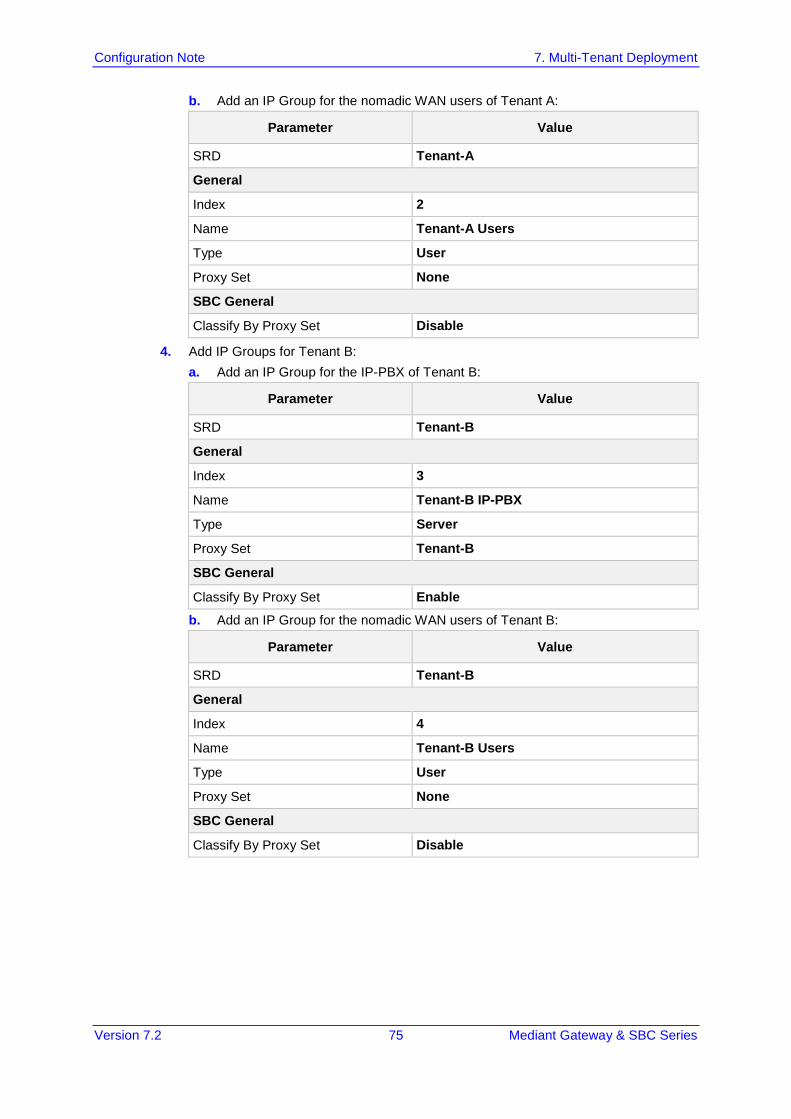
Version 7.2 75 Mediant Gateway & SBC Series
Configuration Note 7. Multi-Tenant Deployment
b. Add an IP Group for the nomadic WAN users of Tenant A:
Parameter Value
SRD Tenant-A
General
Index 2
Name Tenant-A Users
Type User
Proxy Set None
SBC General
Classify By Proxy Set Disable
4. Add IP Groups for Tenant B: a. Add an IP Group for the IP-PBX of Tenant B:
Parameter Value
SRD Tenant-B
General
Index 3
Name Tenant-B IP-PBX
Type Server
Proxy Set Tenant-B
SBC General
Classify By Proxy Set Enable
b. Add an IP Group for the nomadic WAN users of Tenant B:
Parameter Value
SRD Tenant-B
General
Index 4
Name Tenant-B Users
Type User
Proxy Set None
SBC General
Classify By Proxy Set Disable
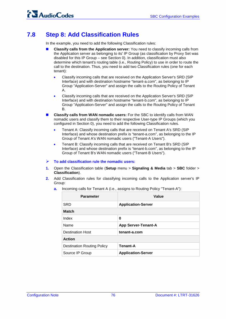
Configuration Note 76 Document #: LTRT-31626
SBC Configuration Examples
7.8 Step 8: Add Classification Rules In the example, you need to add the following Classification rules: Classify calls from the Application server: You need to classify incoming calls from
the Application server as belonging to its' IP Group (as classification by Proxy Set was disabled for this IP Group – see Section 0). In addition, classification must also determine which tenant's routing table (i.e., Routing Policy) to use in order to route the call to the destination. Thus, you need to add two Classification rules (one for each tenant): • Classify incoming calls that are received on the Application Server's SRD (SIP
Interface) and with destination hostname “tenant-a.com", as belonging to IP Group "Application-Server" and assign the calls to the Routing Policy of Tenant A.
• Classify incoming calls that are received on the Application Server's SRD (SIP Interface) and with destination hostname “tenant-b.com", as belonging to IP Group "Application-Server" and assign the calls to the Routing Policy of Tenant B.
Classify calls from WAN nomadic users: For the SBC to identify calls from WAN nomadic users and classify them to their respective User-type IP Groups (which you configured in Section 0), you need to add the following Classification rules. • Tenant A: Classify incoming calls that are received on Tenant A's SRD (SIP
Interface) and whose destination prefix is “tenant-a.com”, as belonging to the IP Group of Tenant A's WAN nomadic users ("Tenant-A Users").
• Tenant B: Classify incoming calls that are received on Tenant B's SRD (SIP Interface) and whose destination prefix is “tenant-b.com”, as belonging to the IP Group of Tenant B's WAN nomadic users ("Tenant-B Users").
To add classification rule the nomadic users:
1. Open the Classification table (Setup menu > Signaling & Media tab > SBC folder > Classification).
2. Add Classification rules for classifying incoming calls to the Application server's IP Group: a. Incoming calls for Tenant A (i.e., assigns to Routing Policy "Tenant-A"):
Parameter Value
SRD Application-Server
Match
Index 0
Name App Server-Tenant-A
Destination Host tenant-a.com
Action
Destination Routing Policy Tenant-A
Source IP Group Application-Server
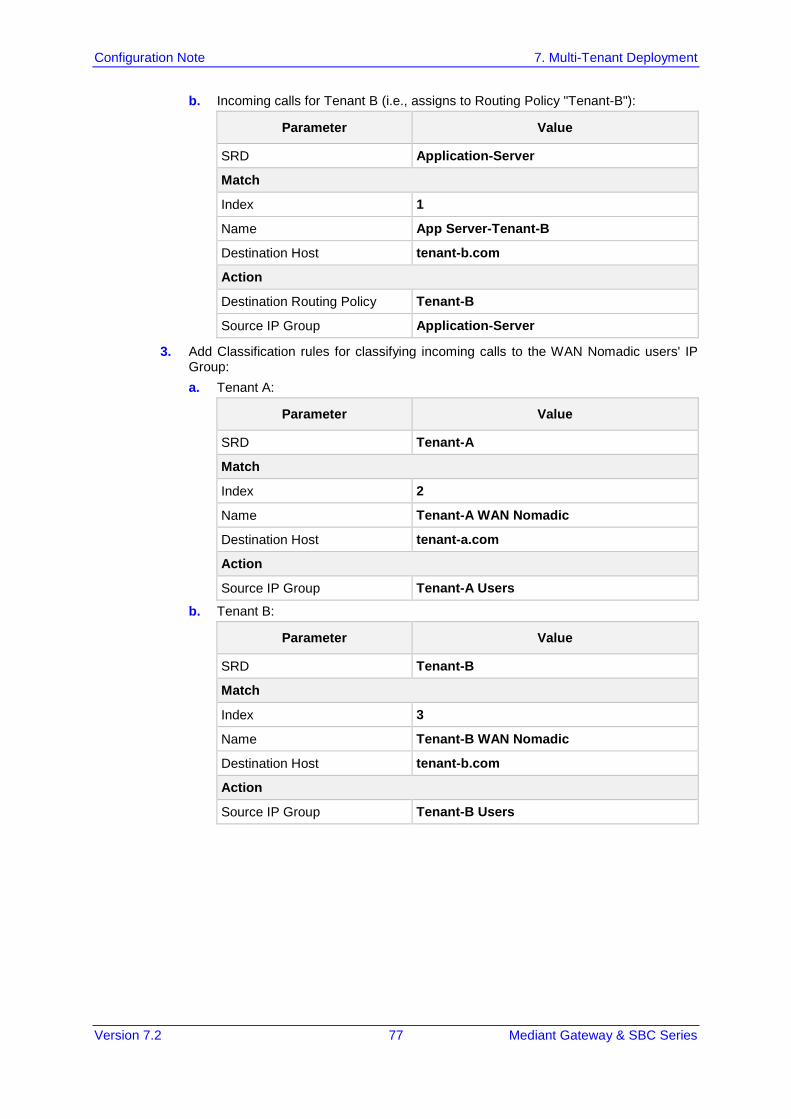
Version 7.2 77 Mediant Gateway & SBC Series
Configuration Note 7. Multi-Tenant Deployment
b. Incoming calls for Tenant B (i.e., assigns to Routing Policy "Tenant-B"):
Parameter Value
SRD Application-Server
Match
Index 1
Name App Server-Tenant-B
Destination Host tenant-b.com
Action
Destination Routing Policy Tenant-B
Source IP Group Application-Server
3. Add Classification rules for classifying incoming calls to the WAN Nomadic users' IP Group: a. Tenant A:
Parameter Value
SRD Tenant-A
Match
Index 2
Name Tenant-A WAN Nomadic
Destination Host tenant-a.com
Action
Source IP Group Tenant-A Users
b. Tenant B:
Parameter Value
SRD Tenant-B
Match
Index 3
Name Tenant-B WAN Nomadic
Destination Host tenant-b.com
Action
Source IP Group Tenant-B Users
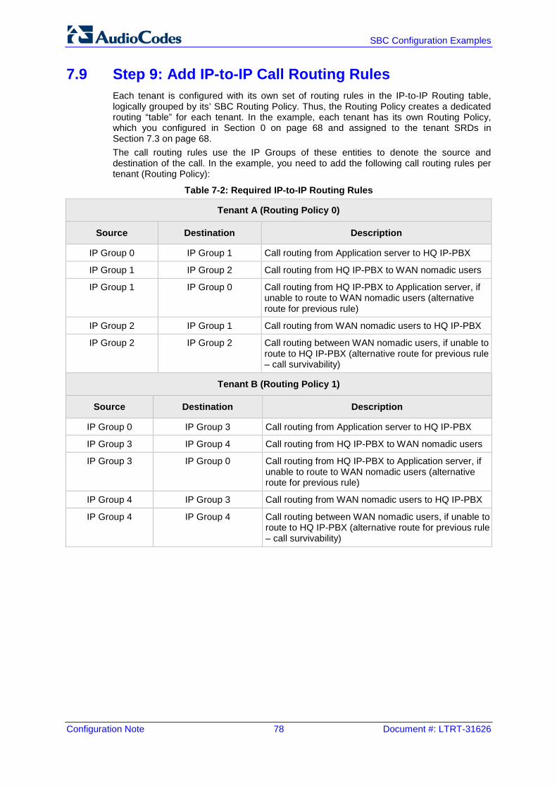
Configuration Note 78 Document #: LTRT-31626
SBC Configuration Examples
7.9 Step 9: Add IP-to-IP Call Routing Rules Each tenant is configured with its own set of routing rules in the IP-to-IP Routing table, logically grouped by its’ SBC Routing Policy. Thus, the Routing Policy creates a dedicated routing “table” for each tenant. In the example, each tenant has its own Routing Policy, which you configured in Section 0 on page 68 and assigned to the tenant SRDs in Section 7.3 on page 68. The call routing rules use the IP Groups of these entities to denote the source and destination of the call. In the example, you need to add the following call routing rules per tenant (Routing Policy):
Table 7-2: Required IP-to-IP Routing Rules
Tenant A (Routing Policy 0)
Source Destination Description
IP Group 0 IP Group 1 Call routing from Application server to HQ IP-PBX
IP Group 1 IP Group 2 Call routing from HQ IP-PBX to WAN nomadic users
IP Group 1 IP Group 0 Call routing from HQ IP-PBX to Application server, if unable to route to WAN nomadic users (alternative route for previous rule)
IP Group 2 IP Group 1 Call routing from WAN nomadic users to HQ IP-PBX
IP Group 2 IP Group 2 Call routing between WAN nomadic users, if unable to route to HQ IP-PBX (alternative route for previous rule – call survivability)
Tenant B (Routing Policy 1)
Source Destination Description
IP Group 0 IP Group 3 Call routing from Application server to HQ IP-PBX
IP Group 3 IP Group 4 Call routing from HQ IP-PBX to WAN nomadic users
IP Group 3 IP Group 0 Call routing from HQ IP-PBX to Application server, if unable to route to WAN nomadic users (alternative route for previous rule)
IP Group 4 IP Group 3 Call routing from WAN nomadic users to HQ IP-PBX
IP Group 4 IP Group 4 Call routing between WAN nomadic users, if unable to route to HQ IP-PBX (alternative route for previous rule – call survivability)
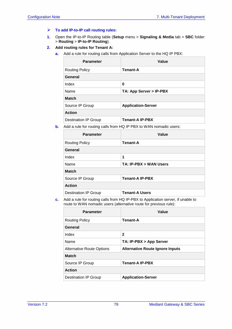
Version 7.2 79 Mediant Gateway & SBC Series
Configuration Note 7. Multi-Tenant Deployment
To add IP-to-IP call routing rules:
1. Open the IP-to-IP Routing table (Setup menu > Signaling & Media tab > SBC folder > Routing > IP-to-IP Routing).
2. Add routing rules for Tenant A: a. Add a rule for routing calls from Application Server to the HQ IP PBX:
Parameter Value
Routing Policy Tenant-A
General
Index 0
Name TA: App Server > IP-PBX
Match
Source IP Group Application-Server
Action
Destination IP Group Tenant-A IP-PBX
b. Add a rule for routing calls from HQ IP PBX to WAN nomadic users:
Parameter Value
Routing Policy Tenant-A
General
Index 1
Name TA: IP-PBX > WAN Users
Match
Source IP Group Tenant-A IP-PBX
Action
Destination IP Group Tenant-A Users
c. Add a rule for routing calls from HQ IP-PBX to Application server, if unable to route to WAN nomadic users (alternative route for previous rule):
Parameter Value
Routing Policy Tenant-A
General
Index 2
Name TA: IP-PBX > App Server
Alternative Route Options Alternative Route Ignore Inputs
Match
Source IP Group Tenant-A IP-PBX
Action
Destination IP Group Application-Server
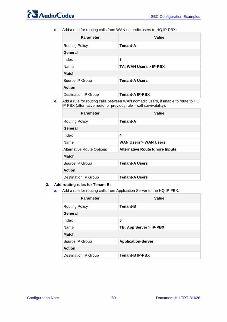
Configuration Note 80 Document #: LTRT-31626
SBC Configuration Examples
d. Add a rule for routing calls from WAN nomadic users to HQ IP-PBX:
Parameter Value
Routing Policy Tenant-A
General
Index 3
Name TA: WAN Users > IP-PBX
Match
Source IP Group Tenant-A Users
Action
Destination IP Group Tenant-A IP-PBX
e. Add a rule for routing calls between WAN nomadic users, if unable to route to HQ IP-PBX (alternative route for previous rule – call survivability):
Parameter Value
Routing Policy Tenant-A
General
Index 4
Name WAN Users > WAN Users
Alternative Route Options Alternative Route Ignore Inputs
Match
Source IP Group Tenant-A Users
Action
Destination IP Group Tenant-A Users
3. Add routing rules for Tenant B: a. Add a rule for routing calls from Application Server to the HQ IP PBX:
Parameter Value
Routing Policy Tenant-B
General
Index 5
Name TB: App Server > IP-PBX
Match
Source IP Group Application-Server
Action
Destination IP Group Tenant-B IP-PBX
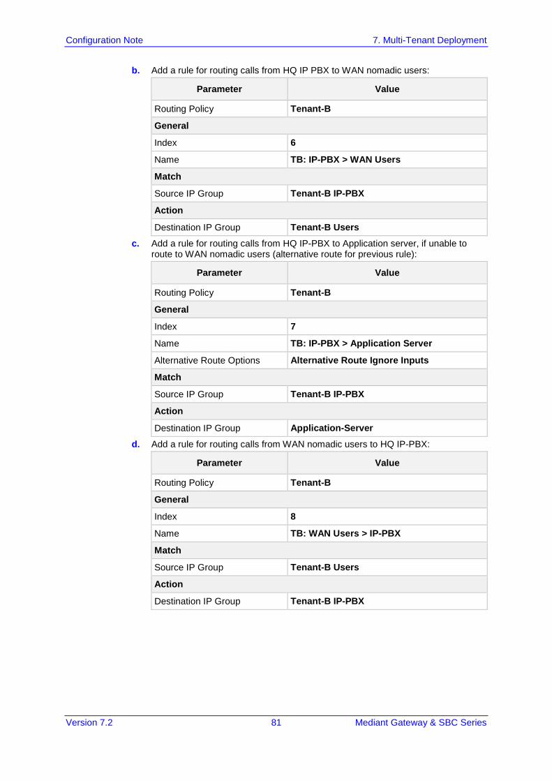
Version 7.2 81 Mediant Gateway & SBC Series
Configuration Note 7. Multi-Tenant Deployment
b. Add a rule for routing calls from HQ IP PBX to WAN nomadic users:
Parameter Value
Routing Policy Tenant-B
General
Index 6
Name TB: IP-PBX > WAN Users
Match
Source IP Group Tenant-B IP-PBX
Action
Destination IP Group Tenant-B Users
c. Add a rule for routing calls from HQ IP-PBX to Application server, if unable to route to WAN nomadic users (alternative route for previous rule):
Parameter Value
Routing Policy Tenant-B
General
Index 7
Name TB: IP-PBX > Application Server
Alternative Route Options Alternative Route Ignore Inputs
Match
Source IP Group Tenant-B IP-PBX
Action
Destination IP Group Application-Server
d. Add a rule for routing calls from WAN nomadic users to HQ IP-PBX:
Parameter Value
Routing Policy Tenant-B
General
Index 8
Name TB: WAN Users > IP-PBX
Match
Source IP Group Tenant-B Users
Action
Destination IP Group Tenant-B IP-PBX
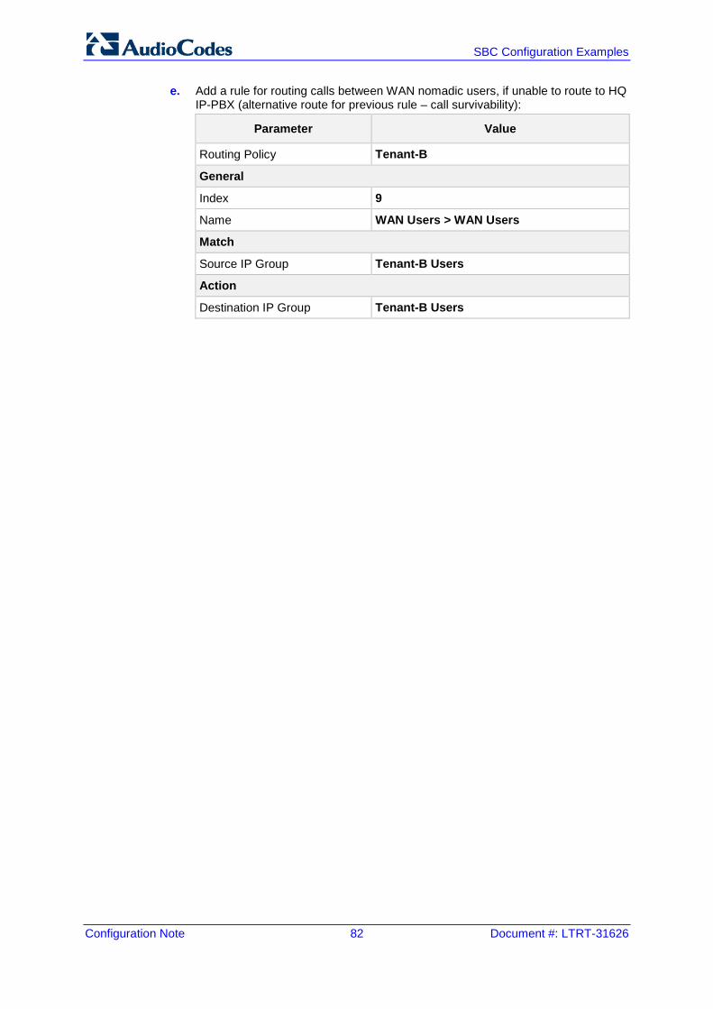
Configuration Note 82 Document #: LTRT-31626
SBC Configuration Examples
e. Add a rule for routing calls between WAN nomadic users, if unable to route to HQ IP-PBX (alternative route for previous rule – call survivability):
Parameter Value
Routing Policy Tenant-B
General
Index 9
Name WAN Users > WAN Users
Match
Source IP Group Tenant-B Users
Action
Destination IP Group Tenant-B Users

Version 7.2 83 Mediant Gateway & SBC Series
Configuration Note 7. Multi-Tenant Deployment
This page is intentionally left blank.
International Headquarters
Contact us: www.audiocodes.com/info Website: www.audiocodes.com
Document #: LTRT-31626