SB-07-018A Linear Bearing Access Panel Installation
22
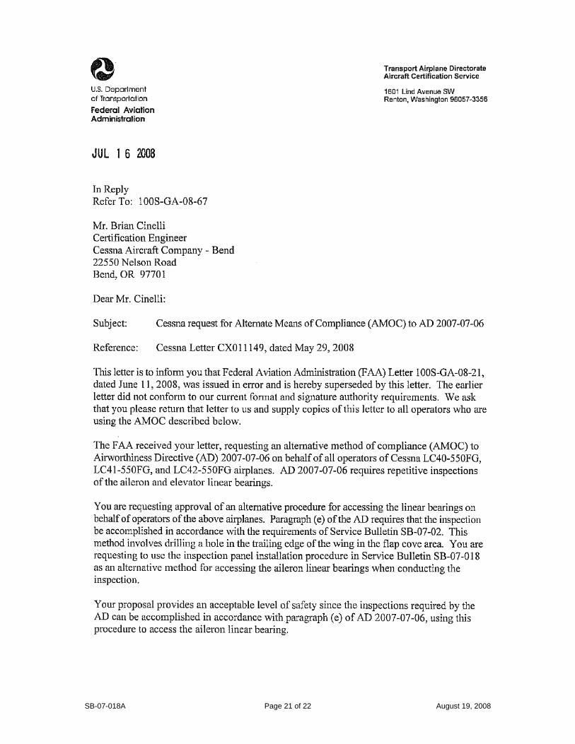
Cessna Aircraft Company, Product Support, P.O. Box 7706, Wichita, Kansas 67277, U.S.A. (316) 517-5800, Facsimile (316) 942-9006 Copyright© 2008 Cessna Aircraft Company cannot be responsible for the quality of work performed by others while fulfilling the requirements of this Service Bulletin. Procedures specified in this Service Bulletin must be accomplished in accordance with the standards and techniques set forth in the approved AMM and all applicable government regulations, standards and advisories. All process and material information referenced within this Service Bulletin is derived from Cessna Aircraft Company FAA approved specifications. Page 1 of 22 SERVICE BULLETIN SB-07-018A Mandatory August 19, 2008 Model 300/350/400 LINEAR BEARING ACCESS PANEL INSTALLATION EFFECTIVITY Model 300/LC40-550FG, airplane serial numbers 40001 through 40079 Model 350/LC42-550FG, airplane serial numbers 42001 through 42568 Model 400/LC41-550FG, airplane serial numbers 41002 through 41786 REVISION HISTORY Rev Description Date - Initial Release 05/30/08 A Added new FAA AMOC letter 100S-GA-08-67, added compliance note regarding accomplishement of initial revision, revised owner advisory. 08/19/08 PURPOSE To provide the parts and procedures necessary to install access panels at wing station WS 86 of the left and right wings. The access panels are designed to help facilitate maintenance/debris removal of the aileron control tube linear bearings for foreign object debris (FOD) as required by Section 5 of the latest revision to the Airplane Maintenance Manual. COMPLIANCE Mandatory, prior to flight if any of the following conditions are found during accomplishment of the aileron linear bearing inspection in accordance with SB-07-002 (any revision) or Section 5 of the Airplane Maintenance Manual: aileron linear bearing damage, attached adhesive, or irretrievable foreign object debris (FOD). Otherwise Optional: may be accomplished if desired. NOTE: If wing access panels have already been installed at wing station WS 86 by another Cessna approved method, compliance with this Service Bulletin is not applicable. NOTE: If the original issue of this Service Bulletin has been previously complied with, then compliance with Revision A or later of this Service Bulletin is not required. The initial release of this Service Bulletin is approved by the FAA Seattle Aircraft Certification Office, by letter 100S-GA-08-67, as an alternative method of compliance with FAA Airworthiness Directive AD 2007-07-06 and a copy of the letter is attached to this Service Bulletin. Compliance with this Service Bulletin is considered as a terminating action for AD 2007-07-06.
Transcript of SB-07-018A Linear Bearing Access Panel Installation

Cessna Aircraft Company, Product Support, P.O. Box 7706, Wichita, Kansas 67277, U.S.A. (316) 517-5800, Facsimile (316) 942-9006 Copyright© 2008
Cessna Aircraft Company cannot be responsible for the quality of work performed by others while fulfilling the requirements of this Service Bulletin. Procedures specified in this Service Bulletin must be accomplished in accordance with the standards and techniques set forth in the approved AMM and all applicable government regulations, standards and advisories. All process and material information referenced within this Service Bulletin is derived from Cessna Aircraft Company FAA approved specifications. Page 1 of 22
SERVICE BULLETIN
SB-07-018A Mandatory August 19, 2008
Model 300/350/400
LINEAR BEARING ACCESS PANEL INSTALLATION
EFFECTIVITY Model 300/LC40-550FG, airplane serial numbers 40001 through 40079 Model 350/LC42-550FG, airplane serial numbers 42001 through 42568 Model 400/LC41-550FG, airplane serial numbers 41002 through 41786 REVISION HISTORY Rev Description Date - Initial Release 05/30/08 A Added new FAA AMOC letter 100S-GA-08-67, added compliance
note regarding accomplishement of initial revision, revised owner advisory.
08/19/08
PURPOSE To provide the parts and procedures necessary to install access panels at wing station WS 86 of the left and right wings. The access panels are designed to help facilitate maintenance/debris removal of the aileron control tube linear bearings for foreign object debris (FOD) as required by Section 5 of the latest revision to the Airplane Maintenance Manual. COMPLIANCE Mandatory, prior to flight if any of the following conditions are found during accomplishment of the aileron linear bearing inspection in accordance with SB-07-002 (any revision) or Section 5 of the Airplane Maintenance Manual: aileron linear bearing damage, attached adhesive, or irretrievable foreign object debris (FOD). Otherwise Optional: may be accomplished if desired. NOTE: If wing access panels have already been installed at wing station WS 86 by another Cessna approved method, compliance with this Service Bulletin is not applicable. NOTE: If the original issue of this Service Bulletin has been previously complied with, then compliance with Revision A or later of this Service Bulletin is not required. The initial release of this Service Bulletin is approved by the FAA Seattle Aircraft Certification Office, by letter 100S-GA-08-67, as an alternative method of compliance with FAA Airworthiness Directive AD 2007-07-06 and a copy of the letter is attached to this Service Bulletin. Compliance with this Service Bulletin is considered as a terminating action for AD 2007-07-06.

SB-07-018A Page 2 of 22 August 19, 2008
APPROVAL FAA approval has been obtained on all technical data in this Service Bulletin that affects type design. RESOURCES 10.8 man-hours per airplane to accomplish this Service Bulletin. Up to 3.0 additional man-hours may be necessary per airplane to paint the access panel joggle assemblies and access panels to match the paint on the lower wing. CREDIT INFORMATION Applicable for airplanes in warranty only as stated below: Credit will be provided only if aileron linear bearing damage, attached adhesive, or irretrievable foreign object debris (FOD) is found as described in the Compliance section of this Service Bulletin. Include a copy of the logbook entries with the Warranty Claim that show compliance with Service Bulletin SB-07-002 (or later revision) and findings of aileron linear bearing damage, attached adhesive, or irretrievable foreign object debris (FOD). Applicable parts credit and a labor allowance credit of 10.8 man-hours per airplane will be provided to accomplish SB-07-018A. If the color of the access panel joggle assemblies and access panels do not match the surrounding color of the lower wing area, up to 3.0 man-hours and a miscellaneous parts credit of $50.00 per airplane will be provided to paint the access panel joggle assemblies and access panels. Freight will be credited at the most economical method unless pre-approved by Cessna. For pre-approval contact Cessna Parts Distribution Warranty Administration at Telephone: 316-831-4296, Fax: 316-206-2746 or E-mail: [email protected]. To receive credit, the work must be completed and a Warranty Claim submitted by a Cessna Single Engine Service Station within 30 calendar days of Service Bulletin compliance before the credit expiration dates shown below.
Domestic . . . . . . . . . . . . . . . . . . . . . . . May 30, 2009 International . . . . . . . . . . . . . . . . . . . . .May 30, 2009
Special Note to Service Stations: When you complete the Warranty Claim, the labor allowance claimed shall be itemized for each above action completed.

SB-07-018A Page 3 of 22 August 19, 2008
OWNER NOTIFICATION A. On June 20, 2008 the following Owner Advisory message was sent to applicable owners of record in SB-07-018 OA. Dear Cessna Owner: This Owner Advisory is to inform you that Cessna Service Bulletin SB-07-018: Linear Bearing Access Panel Installation has been issued. SB-07-018 provides the parts and procedures necessary to install access panels at wing station WS 86 of the left and right wings. The access panels are designed to help facilitate maintenance/debris removal of the aileron control tube linear bearings for foreign object debris (FOD) as required by Section 5 of the latest revision to the Airplane Maintenance Manual. Compliance: Mandatory, prior to flight if any of the following conditions are found during accomplishment of the aileron linear bearing inspection in accordance with SB-07-002 (any revision) or Section 5 of the Airplane Maintenance Manual: aileron linear bearing damage, attached adhesive, or irretrievable foreign object debris (FOD). Otherwise Optional: may be accomplished if desired. NOTE: If wing access panels have already been installed at wing station WS 86 by another Cessna approved method, compliance with this Service Bulletin is not applicable. The initial release of SB-07-018 is approved by the FAA Seattle Aircraft Certification Office, by letter 100S-GA-08-21, as an alternative method of compliance with FAA Airworthiness Directive AD 2007-07-06 and a copy of the letter is attached to Owner Advisory. Compliance with SB-07-018 is considered as a terminating action for AD 2007-07-06. Credit Information: Credit will be applicable for airplanes in warranty only as stated below. Credit will be provided only if aileron linear bearing damage, attached adhesive, or irretrievable foreign object debris (FOD) is found as described in the Compliance section. Include a copy of the logbook entries with the Warranty Claim that show compliance with Service Bulletin SB-07-002 (or later revision) and findings of aileron linear bearing damage, attached adhesive, or irretrievable foreign object debris (FOD). Applicable parts credit and a labor allowance credit of 10.8 man-hours per airplane will be provided to accomplish SB-07-018. If the color of the access panel joggle assemblies and access panels do not match the surrounding color of the lower wing area, up to 3.0 man-hours and a miscellaneous parts credit of $50.00 per airplane will be provided to paint the access panel joggle assemblies and access panels.

SB-07-018A Page 4 of 22 August 19, 2008
To receive credit, the work must be completed and a Warranty Claim submitted by a Cessna Single Engine Service Station within 30 calendar days of Service Bulletin compliance before the credit expiration dates shown below.
Domestic . . . . . . . . . . . . . . . . . . . . . . . May 30, 2009 International . . . . . . . . . . . . . . . . . . . . .May 30, 2009
Please contact a Cessna Single Engine Service Station for detailed information and arrange to have Cessna Service Bulletin SB-07-018 accomplished on your airplane. B. On August 25, 2008 the following Owner Advisory message will be sent to applicable owners of record in SB-07-018A OA1. Dear Cessna Owner: This Owner Advisory is to inform you that Cessna Service Bulletin SB-07-018A: Linear Bearing Access Panel Installation has been issued. SB-07-018 Revision A was issued because the FAA has provided notification that their original letter of June 11, 2008 approving SB-07-018 as an Alternate Method of Compliance (AMOC) with FAA Airworthiness Directive AD 2007-07-06 was issued in error. FAA AMOC letter 100S-GA-08-67 dated July 16, 2008 has been issued and supersedes the original AMOC letter. A copy of the new AMOC letter is attached to this Owner Advisory. All other content aspects of SB-07-018A remain the same as the original issue of SB-07-018. If your airplane is in compliance with the original issue of SB-07-018 then compliance with SB-07-018A is not required. If SB-07-018 has not been accomplished on your airplane, please contact a Cessna Single Engine Service Station for detailed information and arrange to have Cessna Service Bulletin SB-07-018A accomplished on your airplane.
* * * * * * * * * *

SB-07-018A Page 5 of 22 August 19, 2008
MATERIAL INFORMATION The following parts kit is required for compliance with this Service Bulletin. The parts kit is available from Cessna Parts Distribution through an appropriate Cessna Service Station. All other materials should be procured locally (P/L).
ITEM NO. DESCRIPTION P/N OR SPEC. SUPPLIER QUANTITY
Order kit P/N SB-07-018A Linear Bearing Acc which includes the following nine items:
1 Service Bulletin SB-07-018A Cessna 1
2 Jeffco Resin System (includes 1307 Resin and 3102 Hardener) Jeffco Pack 5 Cessna 2
3 Mixed Dry Fillers (includes Micro Filler, Cotton Flock, Cab-O-Sil) Mixed Filler 6.4 Cessna 2
4 Aileron Linear Bearing Joggle Locating Template Set (includes both LH and RH templates)
FA57650015-FL01 Cessna 1
5 Access Panel LA57650015 Rev.- Cessna 2
6 Access Panel Joggle Assembly FA57650015 Rev.- Cessna 2
7 White Silicone Caulk (Mil-A-16146), General Electric RTV-162 Cessna 1 tube
8 6-32 100° countersunk screw MS24693-C29 Cessna 8
9 Anti-chafe tape 1” wide, clear LA57700045 Rev.A Cessna 0.5 feet
In addition to the items above, the following may be procured locally:
1 Isopropyl Alcohol TT-I-735 Grade B or equivalent P/L As required
2 Masking Tape, 1 inch wide 3M Masking Tape or equivalent P/L As required
3 Clear Packing Tape, 2 inch 3M Packing Tape or equivalent P/L As required
4 Plastic Mixing Cup Evercoat “E”-cup or equivalent P/L As required

SB-07-018A Page 6 of 22 August 19, 2008
TOOLS AND EQUIPMENT Refer to the instructions for detailed information.
ITEM NO. DESCRIPTION P/N OR SPEC. SUPPLIER QUANTITY
1 Handheld rotary tool Dremel or equivalent P/L 1
2 Tungsten carbide cutter wheel Dremel 9936 or equivalent P/L 1
3 Sandpaper 80 – 120 grit P/L 1
4 Hot bonder – controller (Preferred Method)
Applied Heat model A150B LB or equivalent
P/L 1
5 Hot bonder – heater (Preferred Method)
Applied Heat model A600 P/L 1
6 Thermocouple (Preferred Method)
Applied Heat “J” type or equivalent P/L 1
7 Cardboard box (Preferred Method)
Approximately 12 inches Wide X 12 inches Long X 10 inches Deep
P/L 1
8 Heat gun (Alternate Method)
Bosch 1942 or equivalent P/L 1
9 Digital thermometer (Alternate Method)
Omega model HH-23 or equivalent P/L 2 minimum
10 Cardboard box (Alternate Method)
Approximately 12 inches Wide X 12 inches Long X 24 inches Deep
P/L 1

SB-07-018A Page 7 of 22 August 19, 2008
INSTRUCTIONS FOR COMPLIANCE
NOTE: Read this Service Bulletin in its entirety prior to performing any steps. 1. Prepare the airplane for maintenance.
A. Make sure that all switches are in the OFF position. B. Disconnect electrical power from the airplane.
(1). Disconnect the airplane battery. (2). Disconnect external electrical power.
C. Attach maintenance warning tags to the battery and external power receptacle that have “DO NOT CONNECT ELECTRICAL POWER – MAINTENANCE IN PROGRESS” written on them.
2. Prior to beginning installation procedures, compare FA57650015 Rev.- Joggle Insert and
LA57650015 Rev.- Access Panel paint color with the airplane wing color. If the paint colors do not adequately match, paint the exterior surfaces ONLY of the FA57650015 Rev.- Joggle Insert and LA57650015 Rev.- Access Panel to match the airplane wing color (refer to Chapter 51 of the applicable Airplane Maintenance Manual). Care should be taken to avoid painting the back side of the FA57650015 Rev.- Joggle Insert as this surface will be bonded to the wing later.
NOTE: Complete the following instructions for one side of the airplane before proceeding to the other. 3. Remove flap. (Refer to Chapter 27 of the applicable Airplane Maintenance Manual).
4. (Figure 1). Use a sharp razor blade to cut and remove the 1” START HOLE from the
FA57650015-FL01 Template.
Figure 1 1” Start Hole peel-off
5. Trim outboard edge of FA57650015-FL01 Template along the INDEX AGAINST
INBOARD EDGE OF WS104.5 FLAP HINGE BASE line.

SB-07-018A Page 8 of 22 August 19, 2008
6. Fold the FA57650015-FL01 Template along both the START OF RADIUS and the END OF RADIUS dashed lines of FA57650015-FL01 Template.
7. Using a tape measure and grease pencil (or equivalent), locate and mark WS 86 on the
aft edge of the lower wing skin.
NOTE: The trailing edge wing flap cove (next to the aileron) is at WS 145. WS 86 can be located by measuring 59-inches inboard of WS 146.
8. (Figure 2 and 3). Locate the FA57650015-FL01 Template on the lower aft edge of the
wing skin by aligning the START OF RADIUS and END OF RADIUS dashed lines against the lower radius of the trailing edge of the flap cove. Line up the outboard edge line INDEX AGAINST INBOARD EDGE OF WS104.5 FLAP HINGE BASE of FA57650015-FL01 Template against the inboard edge of WS104.5 flap hinge base and make sure that the WS 86 line on the FA57650015-FL01 Template lines up with the mark made on the lower wing skin at WS 86.
9. (Figure 2). Temporarily attach the FA57650015-FL01 Template to the lower wing skin
with masking tape.
Figure 2 Template locating features.
Tape down forward edge of template
Line up dashed lines parallel against radiuses of trailing edge of flap cove
Index outboard edge of template against inboard edge of WS104.5 flap hinge base
WS 86 line

SB-07-018A Page 9 of 22 August 19, 2008
Figure 3 Dashed lines against trailing edge of flap cove.
10. (Figure 4) Verify WS 86 line on FA57650015-FL01 Template is 59 inches from the flap
cove at WS145. Adjust the FA57650015-FL01 Template inboard or outboard as necessary while maintaining the START OF RADIUS and the END OF RADIUS dashed lines alignment to the lower radius of the trailing edge flap cove edge. Once verified, mark inboard and outboard edges of FA57650015-FL01 Template on the lower wing skin using a grease pencil (or equivalent).
Figure 4 WS 86 verification
End of Radius
Start of Radius

SB-07-018A Page 10 of 22 August 19, 2008
11. (Figure 5) Using a one inch hole saw (or equivalent), drill a one inch hole in the lower wing skin at the 1” START HOLE location in the FA57650015-FL01 Template.
CAUTION: WING SKIN IS APPROXIMATELY 0.30-INCH THICK AT THIS POINT. DO NOT ALLOW DRILL TO PENETRATE MORE THAN 0.30-INCH PAST THE INNER WING SKIN, OR DAMAGE MAY BE CAUSED TO THE LINEAR BEARING INSIDE THE WING.
Figure 5 One inch hole in lower wing skin
12. (Figure 6). Using a narrow scale through the existing 0.75-inch WS86 trailing edge
inspection hole to the aft spar face, aligning the scale with the wing chord, measure the distance from the leading edge of the circular 1” START HOLE cutout to the aft spar face. This measurement should be between 1.75 – 1.85 inches. If this measurement is not within this range, adjust the FA57650015-FL01 Template forward or aft while maintaining the START OF RADIUS and the END OF RADIUS dashed lines alignment to the lower radius of the trailing edge flap cove edge. Also, maintain FA57650015-FL01 Template within the inboard and outboard marks made on the lower wing skin.
Figure 6 Forward/Aft locating of FA57650015-FL01 Template
13. (Figure 7). Once the 1.75-1.85 inch dimension and the WS86 is verified 59 inches to the
flap cove, flip the FA57650015-FL01 Template over the leading edge masking tape and peel off the backing sheet to expose the adhesive film of FA57650015-FL01 Template.
0.75-inch WS86 trailing edge inspection hole
Measurement from leading edge of 1” hole on template to spar face is 1.75-1.85 inches

SB-07-018A Page 11 of 22 August 19, 2008
Figure 7 Peel off backing sheet of FA57650015-FL01 Template
14. Using a plastic spreader (or equivalent), carefully flip the FA57650015-FL01 Template
over and attach the FA57650015-FL01 Template smoothly against the lower wing skin from the forward taped edge to the trailing edge of the FA57650015-FL01 Template.
15. (Figure 8). Once the FA57650015-FL01 Template is smoothly and securely attached to
the lower wing skin, peel off the protective outer sheet of the FA57650015-FL01 Template.
Figure 8 Peel off protective outer sheet of FA57650015-FL01 Template

SB-07-018A Page 12 of 22 August 19, 2008
16. (Figure 9). Peel off the inner rectangular pattern from the FA57650015-FL01 Template. Cut out the outer face sheet, core, and inner face sheet of the lower skin following the inner rectangular pattern. Take care to avoid cutting into the linear bearing and aileron control rod. Once the cutout is made, insert plastic sheet (or equivalent) inside of the wing to capture debris.
Figure 9 Cut rectangular opening following inner rectangular pattern
17. (Figure 10). Peel off the four circular 3/8 inch patterns labeled “3/8 rivnut clearance
holes”.
Figure 10 Peel off the four 3/8 inch pattern holes
18. (Figures 10 and 11). Drill four 3/8 inch holes through the lower wing skin at the locations
marked on the FA57650015-FL01 Template for the rivnuts. Take care to avoid drilling into the linear bearing and aileron control rod. A drill stop is suggested to avoid damaging existing assemblies beneath the wing skin.

SB-07-018A Page 13 of 22 August 19, 2008
Figure 11 3/8” rivnut clearance holes
19. (Figure 12, 13, and 14). Peel off the outer rectangular pattern and cut and remove the
outer skin sheet and core ONLY. DO NOT CUT THE INNER SKIN. Using a rotary tool with the Dremel Model 9936 Tungsten Carbide Cutter (or equivalent), de-core 1 to 2 cells beyond the outer rectangular pattern between the face sheets.
NOTE: Be careful not to cut through the inner face skin sheet, particularly at the trailing edge where the core starts to bevel.
Figure 12 Removal of outer face sheet and core following outer rectangular pattern
Figure 13 Removal of outer face sheet and core following outer rectangular pattern
Trailing edge core bevel

SB-07-018A Page 14 of 22 August 19, 2008
Figure 14 Removal of outer face sheet and core following outer rectangular pattern
20. Test fit the FA57650015 Rev.- Joggle Insert into the lower wing cutout and trim the inner
skin to allow clearance of rivnut fasteners pre-installed in the FA57650015 Rev.- Joggle Insert.
NOTE: ONLY trim away portions of the inner skin that contact the rivnut and the exterior skin that contacts the joggle outer edge. NOTE: A 0.06 to 0.10 inch gap between FA57650015 Rev.- Joggle Insert and exterior of the lower wing skin will provide the best finished results.
21. Remove the FA57650015-FL01 Template from the lower wing skin and discard. 22. Thoroughly clean interior area of the wing of all loose debris and sanding particles. 23. Prepare surface of FA57650015 Rev.- Joggle Insert and inner wing skin by sanding with
80-120 grit sandpaper. Clean surface with isopropyl alcohol. Surface prep is only valid for two hours.
24. Mix 5 fl oz (per joggle) of Jeffco 1307 Resin and Jeffco 3102 hardener 100:22-28 by
weight (100 parts resin mixed with 22-28 parts hardener). The pot life of the resin is 11-15 minutes and very sensitive to temperature. Care must be taken in preparation to ensure adequate time to complete entire repair before pot life is exceeded. If ambient temperature is above 80°F it is recommended to mix bonding material in separate batches for each wing. Additionally, at elevated temperatures, large quantities of resin left in a mixing cup are susceptible to thermal runaway. If a large quantity of resin with fillers is left after the repair, distribute into several containers and allow to cure.
CAUTION: Do not mix resin or attempt to install the joggles if ambient temperature is above 100°F. Mixing the resin or installing the joggles above 100°F will cause the resin to cure before the joggle can properly be bonded into the wing.

SB-07-018A Page 15 of 22 August 19, 2008
NOTE: When mixing resins, only use clean plastic or glass mixing cups. Use of a waxed paper cup could introduce contaminates into the resin mixture.
25. Once Jeffco resin is mixed, put 1 fl oz into a separate container for priming.
26. Mix one package (6.4 fl oz) of mixed dry fillers with the remaining 4 fl oz of Jeffco resin that was prepared in Step 24 (refer to tolerances in Table 1 below). Higher ambient temperatures will favor less filler to achieve a non-sagging paste while cooler ambient temperatures will favor using all of the material included in the kit.
Table 1: Adhesive Paste Mixture
Material Amount Volume Ratio Resin mixture 4 fluid oz (equal to 4.64 oz in weight) ± 10% 1.0 fl oz
Dry filler mixture 6.4 fluid oz ± 10% 1.6 fl oz 27. Prime the contact surface of the inner skin of the lower wing by wetting with the 1 fl oz of
mixed resin without fillers. 28. Prime the contact surface of the FA57650015 Rev.- Joggle Insert by wetting with the 1 fl
oz mixed resin without fillers.
29. (Figure 15) Apply Jeffco adhesive paste to de-cored region, completely filling the gap between inner and outer wing skin surfaces.
Figure 15 Adhesive paste applied to de-cored region
30. (Figure 16) Apply a .250 – .350 inch layer of adhesive paste to the inner face of the
FA57650015 Rev.- Joggle Insert to bond to the wing skin.

SB-07-018A Page 16 of 22 August 19, 2008
Figure 16 FA57650015 Rev.- Joggle Insert with adhesive paste applied.
31. Position FA57650015 Rev.- Joggle Insert into cutout, and ensure exterior surface of
FA57650015 Rev.- Joggle Insert contour is flush with the surface of the wing. NOTE: Make sure that you do not apply adhesive to the threaded parts of the rivnuts.
32. Gently clean all excess adhesive squeeze out from around FA57650015 Rev.- Joggle Insert using a clean, lint free cloth moist with isopropyl alcohol.
a. Carefully wipe adhesive from the gap between the exterior wing skin and the FA57650015 Rev.- Joggle Insert contour. Create a 0.05 inch depression in the bonding paste at this interface to provide a channel to install the white silicone caulking.
33. Double check surface contour and secure FA57650015 Rev.- Joggle Insert to ensure it
does not move during cure. a. Contour can be maintained by using tongue depressors or paint sticks (covered
in clear packing tape to prevent adhesion) taped over the edge of the FA57650015 Rev.- Joggle Insert and the lower wing skin.
34. Allow Jeffco paste to pre cure for a minimum of 3 hours at 77°F before beginning the final
cure process. 35. Perform the final cure for the left FA57650015 Rev.- Joggle Insert and the right
FA57650015 Rev.- Joggle Insert per either the Preferred Method (Step 35A) or the Alternate Method (Step 35B) below:
A. (Figure 17) Preferred Method:
(1) Create a box enclosure using a Cardboard box approximately 12 inches wide, 12 inches long, and 10 inches deep and tape together as necessary. (2) Cut an inlet hole in the box for the Hot bonder heater. (3) Cut a one-inch vent hole in the side of the box. (4) Secure the Thermocouple lead as close to the center of the FA57650015 Rev.- Joggle Insert as possible with tape on the wing. (5) Seal the interior of the FA57650015 Rev.- Joggle Insert cut out in the lower wing skin with cardboard or similar material to help prevent heat migration

SB-07-018A Page 17 of 22 August 19, 2008
through the rest of the wing interior. (6) Attach the Cardboard box to the lower wing skin over the FA57650015 Rev.- Joggle Insert with tape. Make sure you do not move the Thermocouple lead when attaching the Cardboard box to the wing. (7) Attach the Hot bonder heater duct to the inlet hole created in Step 35A(2) with tape. (8) Connect the Hot bonder controller to the Hot bonder heater per the manufacturer’s instructions and begin the curing process. Use Table 2 as a guide for curing temperatures and times. (9) Go to Step 36.
B. (Figure 18) Alternate Method:
(1) Create a box enclosure using a Cardboard box approximately 12 inches wide, 12 inches long, and 24 inches deep and tape together as necessary. (2) Cut an inlet hole in the box for the Heat gun. (3) Cut a six inch vent hole (creating a flap) in the side of the box. (4) Secure a minimum of two Digital Thermometer leads as close to the center of the FA57650015 Rev.- Joggle Insert as possible with tape on the wing similar to the Thermocouple installation as shown in Figure 17. (5) Seal the interior of the FA57650015 Rev.- Joggle Insert cut out in the lower wing skin with Cardboard or similar material to prevent heat migration through the rest of the wing interior. (6) Attach the Cardboard box to the lower wing skin over the FA57650015 Rev.- Joggle Insert with tape. Make sure you do not move the Digitial Thermometer leads when attaching the cardboard box to the wing. (7) Position the Heat gun so it will blow heat into the inlet hole created in Step 35B(2).
CAUTION: When using the Alternate Method, you must closely monitor the process to not over heat the FA57650015 Rev.- Joggle Insert and wing.
(8) Turn the Heat gun on and begin the curing process. Use Table 2 as a guide for curing temperatures and times. (9) Continually monitor the Digital Thermometers, to make sure that the FA57650015 Rev.- Joggle Insert and wing do not over heat. Cut additional vent holes in the side of the Cardboard box as necessary, to provide a steady temperature that is within the limits per Table 2.
(10) Go to Step 36.

SB-07-018A Page 18 of 22 August 19, 2008
Figure 17 Left: suggested placement of thermocouple, right: hot bonder controller and heater installation with box enclosure.
Figure 18 Left: alternate heat source using heat gun and digital thermometers, right: detail of box enclosure showing vent opening.
Thermocouple placement
Box enclosure Heater Controller
Box enclosure
Box enclosure with vent opening
Heat gun
Digital thermometer
Thermocouple
Two digital thermometers

SB-07-018A Page 19 of 22 August 19, 2008
36. Cure per Table 2 below:
Table 2: Cure Time Cure Temperature (°F) Cure Time (hours)
77 168 87 76 97 40
107 24 117 16 127 11 137 8.0 147 6.1 157 4.8 167 4.0 177 3.3 187 2.8 197 2.4 207 2.1 217 1.9
37. Remove the cardboard box enclosure and material installed in the wing in Step 35. 38. Use 120 grit sandpaper and lightly sand by hand any excess adhesive from the channel
created in Step 32a to provide adequate adhesion for caulking.
39. Clean area thoroughly using isopropyl alcohol and allow to air dry.
40. Fill the 0.05 inch gap between the FA57650015 Rev.- Joggle Insert and wing skin with white silicon caulking (RTV-162). Wipe off the excess so caulking is flush with wing skin.
41. Allow caulking to cure for 4.0 hours at 70°F to 80°F.
Figure 19 Completed joggle contour installation
42. Thoroughly clean wing section of all loose debris and sanding particles.
43. Install access panel using four MS24693-C29 screws.

SB-07-018A Page 20 of 22 August 19, 2008
44. If present, inspect 0.75 inch round inspection hole located in flap cove at WS86. If the clear tape that covers the inspection hole is missing or loose, replace with a new section of LA57700045 Rev.A clear anti-chafe tape.
45. Repeat Steps 3 through 44 for the opposite wing.
46. Re-install flaps. (Refer to Chapter 27 of the applicable Airplane Maintenance Manual).
47. Make a logbook entry stating compliance with this Service Bulletin, SB-07-018A.
SB-07-018A Page 21 of 22 August 19, 2008

SB-07-018A Page 22 of 22 August 19, 2008