SAUTER TVM-N - KERN & SOHN GmbH · TVM-N-BA-e-1616 3 1 Introduction . TVM-N test stand can measure...
15
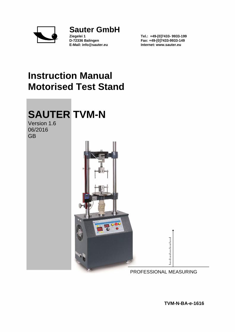
Sauter GmbH Ziegelei 1 D-72336 Balingen E-Mail: [email protected] Tel.: +49-[0]7433- 9933-199 Fax: +49-[0]7433-9933-149 Internet: www.sauter.eu Instruction Manual Motorised Test Stand SAUTER TVM-N Version 1.6 06/2016 GB TVM-N-BA-e-1616 PROFESSIONAL MEASURING
Transcript of SAUTER TVM-N - KERN & SOHN GmbH · TVM-N-BA-e-1616 3 1 Introduction . TVM-N test stand can measure...
Sauter GmbH Ziegelei 1 D-72336 Balingen E-Mail: [email protected]
Tel.: +49-[0]7433- 9933-199 Fax: +49-[0]7433-9933-149 Internet: www.sauter.eu
Instruction Manual Motorised Test Stand
SAUTER TVM-N Version 1.6 06/2016 GB
TVM-N-BA-e-1616
PROFESSIONAL MEASURING
2 TVM-N-BA-e-1616
GB
SAUTER TVM-N Version 1.6 06/2016 Instruction Manual Motorized Test Stand
Thank you for purchasing the SAUTER TVM-N series test stand. We hope you are pleased with your high quality equipment and with its big functional range. With correct use, it will give you many years of accurate and reliable service.If you have any queries, wishes or helpful suggestions, do not hesitate to call our service number or ask your SAUTER distributor for additional information or just visit our website at www.sauter.eu Summary: 1 Introduction .................................................................................................... 3
2 Scope of delivery ........................................................................................... 3
3 Weight and Dimensions ................................................................................ 3
4 Checking before use ...................................................................................... 3
5 Operation Overview ....................................................................................... 3
6 Specifications ................................................................................................ 4
7 Overview ......................................................................................................... 5
8 Control panel .................................................................................................. 5
9 Operation example ......................................................................................... 6 9.1 Examination before test:.......................................................................................................... 6 9.2 Speed adjustment ..................................................................................................................... 7 9.3 How to pre-set Cycles .............................................................................................................. 7 9.4 RS 232 Interface ........................................................................................................................ 7 9.5 Limit Function ........................................................................................................................... 7
10 Warning .......................................................................................................... 8
11 Assembling instruction to a complete measurement system with internal and external force measuring cell ........................................................................... 8
12 Cabling of TVM-N with a SAUTER force gauge and a length measuring device ...................................................................................................................... 13
13 Declaration of Conformity ........................................................................... 15
TVM-N-BA-e-1616 3
1 Introduction TVM-N test stand can measure tension and compression forces very exactly and it is easy to operate. There can be mounted several force gauges from SAUTER to the test stand. It is a motorized test stand which provides you a possibility to move up and down with a constant speed, to make your measuring more accurate and repeatable. SAUTER offers many kinds of accessories optionally, to give you a versatile possibility of application for your measurement system. Please contact us directly or ask your reseller for more information. We also recommend to visit our website www.sauter.eu
2 Scope of delivery
- SAUTER TVM-N - Power cable - Instruction manual
3 Weight and Dimensions Proper weight: 58 kg Dimensions in standard version (TVM 5000N230N): LxBxH: 400x256x1015mm Packing: stable wooden box
4 Checking before use After having received the equipment, please check that no physical damage has occurred to the packaging material, to the wooden box or the test stand itself. If any damage is apparently, please contact SAUTER Company immediately.
5 Operation Overview TVM-N Series Test Stand can be specially applied with nearly all of the SAUTER series Force Gauge for tension and compression tests. lt possesses presetting speed, a wide application range, advantage of non-polar speed adjustment, manual or automatic operation, suitable for application in fields of rubber & plastics, textile, construction, complex material, wires & cables, automobile accessories, engine and scientific research, etc. lt can be connected to a computer, when applied with SAUTER series force gauge, the test stand can be controlled, moving it up or down by our software AFH. Most of the SAUTER series force gauges also can preset the force stop, when the force has arrived the preset one, the test stand will auto-stop.
• Choose the right test stand depend on your request (see Chapter 6). Please do not test over maximum load of the test stand or the mounted force gauge.
4 TVM-N-BA-e-1616
Adapt the force gauge you are going to use to the max. force or just be very carefully in adjusting the travelling distance (the force gauge might be damaged irrevocably!)
• Please do not open, to repair or to modify the equipment. This is not allowed, because you could damage the test stand. Please contact SAUTER GmbH.
• The equipment is not suitable for use in humid surroundings. Please avoid water or any liquids entering the housing, this could damage the mechanical drive.
• Please do not use any sharp-edged tools to operate the buttons of the control panel.
• Use the limit function with the limiting rings to control the travelling distance. An exact adjustment with the help of the limiting rings can avoid damaged of the test stand and the force gauge applied.
• Add a little bit of lubricating grease to the columns of the test stand after a long time of work
• Turn off the equipment when you won’t use it in short time, pull out the power plug when you do not use it for a longer period of time. Do not expose the equipment to humidity and dust.
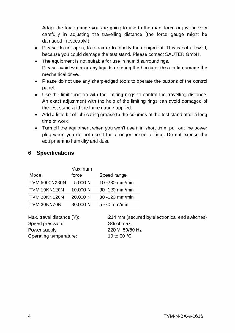
6 Specifications
Model Maximum force Speed range
TVM 5000N230N 5.000 N 10 -230 mm/min TVM 10KN120N 10.000 N 30 -120 mm/min TVM 20KN120N 20.000 N 30 -120 mm/min TVM 30KN70N 30.000 N 5 -70 mm/min
Max. travel distance (Y): 214 mm (secured by electronical end switches) Speed precision: 3% of max. Power supply: 220 V; 50/60 Hz Operating temperature: 10 to 30 °C
TVM-N-BA-e-1616 5
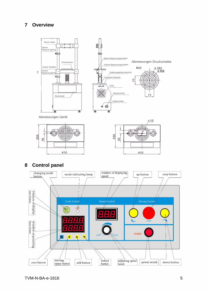
7 Overview
8 Control panel
M12
6 TVM-N-BA-e-1616
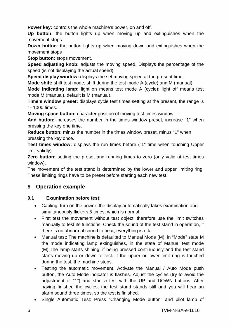
Power key: controls the whole machine's power, on and off. Up button: the button lights up when moving up and extinguishes when the movement stops. Down button: the button lights up when moving down and extinguishes when the movement stops Stop button: stops movement. Speed adjusting knob: adjusts the moving speed. Displays the percentage of the speed (is not displaying the actual speed) Speed display window: displays the set moving speed at the present time. Mode shift: shift test mode, shift during the test mode A (cycle) and M (manual). Mode indicating lamp: light on means test mode A (cycle); light off means test mode M (manual), default is M (manual). Time’s window preset: displays cycle test times setting at the present, the range is 1- 1000 times. Moving space button: character position of moving test times window. Add button: increases the number in the times window preset, increase "1" when pressing the key one time. Reduce button: minus the number in the times window preset, minus "1" when pressing the key once. Test times window: displays the run times before ("1" time when touching Upper limit validly). Zero button: setting the preset and running times to zero (only valid at test times window). The movement of the test stand is determined by the lower and upper limiting ring. These limiting rings have to be preset before starting each new test.
9 Operation example
9.1 Examination before test: • Cabling; turn on the power, the display automatically takes examination and
simultaneously flickers 5 times, which is normal; • First test the movement without test object, therefore use the limit switches
manually to test its functions. Check the sound of the test stand in operation, if there is no abnormal sound to hear, everything is o.k.
• Manual test: The machine is defaulted to Manual Mode (M), in “Mode” state M the mode indicating lamp extinguishes, in the state of Manual test mode (M).The lamp starts shining, if being pressed continuously and the test stand starts moving up or down to test. If the upper or lower limit ring is touched during the test, the machine stops.
• Testing the automatic movement. Activate the Manual / Auto Mode push button, the Auto Mode indicator is flashes. Adjust the cycles (try to avoid the adjustment of “1”) and start a test with the UP and DOWN buttons. After having finished the cycles, the test stand stands still and you will hear an alarm sound three times, so the test is finished.
• Single Automatic Test: Press “Changing Mode button” and pilot lamp of

TVM-N-BA-e-1616 7
“AUTO” is on. A (Auto cycle) mode test is working. Press the UP or DOWN button, the lamp is on and the machine works to test. If “Changing Mode button” is pressed again, “AUTO” is off and you enter Manual test mode. Now the equipment keeps the original moving direction. If during the test the upper or lower limit ring is touched, the test stand stops working and the test is finished.
9.2 Speed adjustment Speed can be adjusted infinitely up to the max. possible speed before or during the test. This is displayed at the “Speed display window” if you adjust the speed with the “Adjusting Speed knob” The adjusted speed can be read on the display.
9.3 How to pre-set Cycles It is possible to preset the number of cycles at the test stand. The pre-set value is shown in the sector below. It can be pre-set by the “add button” and “reduce button” as well as “moving space button”. In the upper sector the number of the run cycles is displayed. It is possible to backspace (clean to zero) the display with the help of “zero button”. Besides, single cycle times are better controlled within 2 hours, which aims to protect the machine and use it properly.
9.4 RS 232 Interface This Test Stand is connected to the outside equipment by the RS-232 interface. The test stand is connected to the computer by RS-232, installing the SAUTER software (optional available, AFH-FAST/FD) from the CD to control movements up and down, to adjust the number of cycles directly at the PC and also the stop function of the test stand. By means of our software you can evaluate all data in relation to force, time or displacement Connecting the port of the test stand to a SAUTER force gauge, the test stand can be piloted and there is the possibility of an overload protection; due to a parameter stop at the gauge; it can also record the force value curve. Due to the inertia of the machine, the force value displayed on the force gauge Will show overload when the test stops automatically. The value of the overload changes from the rigidity of the testing material. You can choose an appropriate low testing speed, or reduce the stop value accordingly.
9.5 Limit Function In M (Manual) test mode, the movement will be stopped after the limit switches are achieved. In A( Automatic) test mode, the movement stops for about 3-5 seconds, reaching the limit switches and then starts again to move in opposite direction. To guarantee an unobstructed working flow for the tests, please take care that the limit switches are positioned as exactly as possible, not to destroy the test equipment or the test object at a too long/short travel distance.
8 TVM-N-BA-e-1616
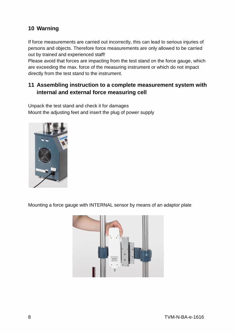
10 Warning If force measurements are carried out incorrectly, this can lead to serious injuries of persons and objects. Therefore force measurements are only allowed to be carried out by trained and experienced staff! Please avoid that forces are impacting from the test stand on the force gauge, which are exceeding the max. force of the measuring instrument or which do not impact directly from the test stand to the instrument.
11 Assembling instruction to a complete measurement system with internal and external force measuring cell
Unpack the test stand and check it for damages Mount the adjusting feet and insert the plug of power supply
Mounting a force gauge with INTERNAL sensor by means of an adaptor plate

TVM-N-BA-e-1616 9
Force gauge with internal force cell mounting, finished:
Mounting of force gauges with EXTERNAL force measuring cell, starting from FH 1KN
Tighten the force gauge with an Allen key M3 at all 4 screws M3x8 (screws are included in delivery of the force gauges)
Removal of the existing adaptor plate for force gauges with internal force measuring cell with an Allen key M6

10 TVM-N-BA-e-1616
The external force measuring cell hast tob e mounted at the fitting bracket AFM 41 with a M12x40 screw (at TVM 5KN and 10KN) and with a M12x80 screw (at
TVM20KN and TVM 30KN), included in delivery.
Fixing the fitting bracket AFM 41 with M6x35 Allen screws steadily with an Allen key
Fitting bracket AFM 41with Allen screws M6 x 35
TVM-N-BA-e-1616 11
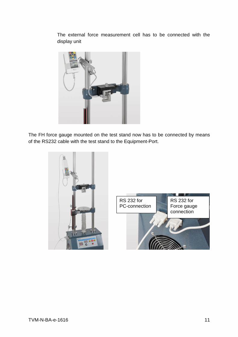
The external force measurement cell has to be connected with the display unit
The FH force gauge mounted on the test stand now has to be connected by means of the RS232 cable with the test stand to the Equipment-Port.
RS 232 for PC-connection
RS 232 for Force gauge connection
12 TVM-N-BA-e-1616
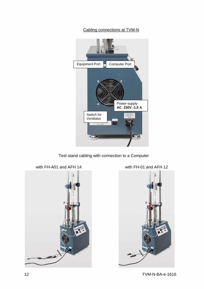
Cabling connections at TVM-N
Test stand cabling with connection to a Computer
with FH-A01 and AFH 14 with FH-01 and AFH 12
Power-supply AC 230V ;1,5 A
Switch for Ventilator
Computer Port
Equipment Port
TVM-N-BA-e-1616 13
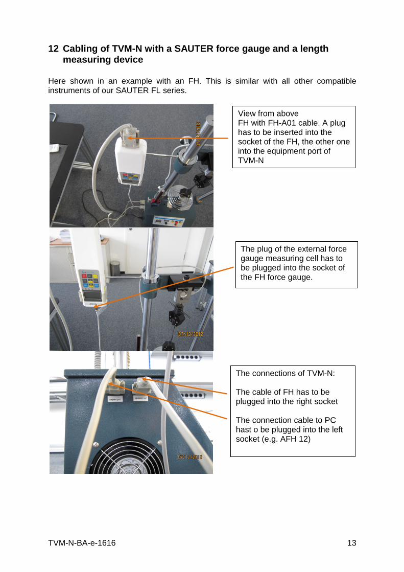
12 Cabling of TVM-N with a SAUTER force gauge and a length measuring device
Here shown in an example with an FH. This is similar with all other compatible instruments of our SAUTER FL series.
View from above FH with FH-A01 cable. A plug has to be inserted into the socket of the FH, the other one into the equipment port of TVM-N
The connections of TVM-N: The cable of FH has to be plugged into the right socket The connection cable to PC hast o be plugged into the left socket (e.g. AFH 12)
The plug of the external force gauge measuring cell has to be plugged into the socket of the FH force gauge.
14 TVM-N-BA-e-1616
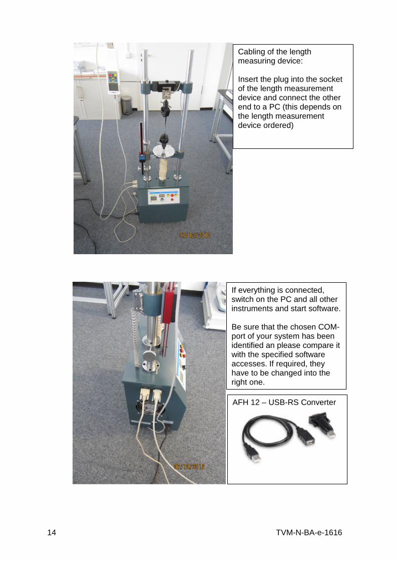
Cabling of the length measuring device: Insert the plug into the socket of the length measurement device and connect the other end to a PC (this depends on the length measurement device ordered)
If everything is connected, switch on the PC and all other instruments and start software. Be sure that the chosen COM-port of your system has been identified an please compare it with the specified software accesses. If required, they have to be changed into the right one.
AFH 12 – USB-RS Converter

TVM-N-BA-e-1616 15
13 Declaration of Conformity
Sauter GmbH Ziegelei 1 D-72336 Balingen E-Mail: [email protected]
Ziegelei 1 D-72336 Balingen E-Mail: [email protected]
Konformitätserklärung Declaration of conformity for apparatus with CE mark
Konformitätserklärung für Geräte mit CE-Zeichen Déclaration de conformité pour appareils portant la marque CE
Declaración de conformidad para aparatos con marca CE Dichiarazione di conformità per apparecchi con la marcatura CE
D Konformitäts-
erklärung Wir erklären hiermit, dass das Produkt, auf das sich diese Erklärung bezieht, mit den nachstehenden Normen übereinstimmt.
GB Declaration of conformity
We hereby declare that the product to which this declaration refers conforms with the following standards.
E Declaración de conformidad
Manifestamos en la presente que el producto al que se refiere esta declaración está de acuerdo con las normas siguientes
F Déclaration de conformité
Nous déclarons avec cela responsabilité que le produit, auquel se rapporte la présente déclaration, est conforme aux normes citées ci-après.
I Dichiarazione di conformità
Dichiariamo con ciò che il prodotto al quale la presente dichiarazione si riferisce è conforme alle norme di seguito citate.
Motorised Test Stand: TVM-N, TVM, TVO EU-Richtlinien Normen
EN 61326:1998+A1:1998+A2:2001
Signatur Signatur
Datum Date
07.04.2014
Ort der Ausstellung Place of issue
72336 Balingen Albert Sauter SAUTER GmbH
Geschäftsführer director
SAUTER GmbH, Ziegelei 1, D-72336 Balingen, Tel.: +49-[0]7433/9933-199
Fax: +49-[0]7433/9933-149, E-Mail: [email protected], Internet: www.sauter.eu