SAULT STE. MARIE, ONTARIO COURSE OUTLINE
26
.. Course Title: Code No.: Program: Semester: Date: Author: . APPROVED: -- 1 - SAULT COLLEGE OF APPLIED ARTS & TECHNOLOGY SAULT STE. MARIE, ONTARIO COURSE OUTLINE MICROWAVE AND RADAR ELN 203-6 ELECTRONIC TECHNOLOGY FIFTH r~a y 26, 1 98 3 NOR~1 BARKER New: Revision: If/'S] - i:: - 2 7 Date
Transcript of SAULT STE. MARIE, ONTARIO COURSE OUTLINE
..
Course Title:
Code No.:
Program:
Semester:
Date:
Author: .
APPROVED:
--
1 -
SAULT COLLEGE OF APPLIED ARTS & TECHNOLOGY
SAULT STE. MARIE, ONTARIO
COURSE OUTLINE
MICROWAVE AND RADAR
ELN 203-6
ELECTRONIC TECHNOLOGY
FIFTH
r~ay 26, 1 98 3
NOR~1 BARKER
New: Revision:
If/'S] -i:: -2 7Date
- - .- -_.---
- 2
Microwave and Radar
Course NameEUJ 20 3 - 6
Course Nunber
PHILOSOPHY/GOALS:
Through a physical rather than mathematical approach,this course will develop in the graduates a thorouahunderstanding of microwave generation and transmission,together ~ith skills in micro~ave systems measurements.In addition the graduate will receive a general background inradar principles.
METHODOF ASSESSMENT(GRADINGMETHOD):
Stud~nt performance will be evaluated by means ofwritten tests, q~izzes, and at least one seminarpresentation with a supporting paper. Microwavemeasurement skills will b~ evaluated through on-going subjective judgement of individual participationin laboratory exercises together with written reports.Grading wi II be as follows:
ABCX
766655Less
100%75%65%than 55%
TEXTBOOK(S):
INTRODUCTION TO MICROWAVE THEORY AND MEASUREMENTS'(A.L. Lance)
- -- -- -
MICROWAVE& RADAR
ElN 203-6
TEXTS: Introduction to Microwave Theory and Measurements (A. L. LANCE)
Technical r~anual - Radar Type 0202 (Decca Radar Ltd.)
Microwave Theory & Measurements(H.P.)
Hewlett Packard Application Notes
REFERENCE TEXTS:
Microwave Theory and Application (Stephen F. Adam)
Principles of Radar (M.I.T. Radar School Staffs)
Microwave Semiconductor Devices and Circuit Applications(H. A. Watson)
Introduction to Radar Systems (Skolnik)
Hewlett-Packard Application Notes
Introduction to Microwaves (Wheeler)
Generation and Transmission of Microwave Energy(U.S. Army, TM11-673)
- - - -- - -- - - - ----

Block 1
Block 2
Block 3 7
TOl>I C
1
2
3
4
5
6
COURSEOUTLINE
PeriodsLec Lab
Topic Description
6 Review Transmission Line Theory
6 WaveguidesPropagation within rectangular
waveguidesFormation of). g wave patternsModes of operationGroup & phase velocitiesMethods of couplingWaveguide HardwareCylindrical Waveguides
Waveguide ComponentsImpedance Matching DevicesTerminationsWaveguide JunctionsDirectional CouplersRadiating ElementsFerrite Devi ces
4 3
1 2 Microwave Dectors
2Cavity ResonatorsFi el d PatternsTuning MethodsApplications
1
6MicrowaveKlystronMagnetronTravellingBackward -
Sources (vacuum tube)6
wave tubewave osci 11ator
1Microwave Semiconductor Devices 5Gunn DiodeYig TuningPin Diode Modulator & source levellingStep Recovery Diode & Harmonic
GenerationImpatt Diode
3
3 20Microwave MeasurementFrequencyPowerAttenuat ionS.W.R.ImpedanceSmith Chart ApplicationsMicrowave Measuring Instruments
- theory of operat ionMicrowave Detectors
--- - --- _ _-L-
Assignment
1
2
3
4
6
7
TOPIC
B1od 4 8
9
Block 5 10
COURSEOUTLINE
PeriodsLec Lab
Topic Description Assignment
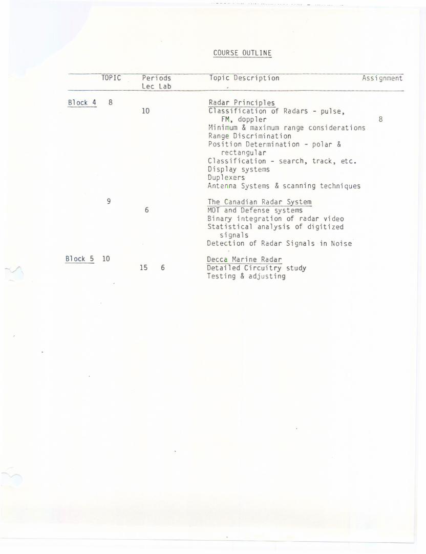
10Radar PrinciplesClassification of Radars - pulse,
FM, dopplerMinimum& maximumrange considerationsRange DiscriminationPosition Determination - polar &
rectangularClassification - search, track, etc.Display systemsDuplexersAntenna Systems & scanning techniques
8
6The Canadian Radar SystemMOTand Defense systemsBinary integration of radar videoStatistical analysis of digitized
signalsDetection of Radar Signals in Noise
15Decca Marine RadarDetailed Circuitry studyTesting & adjusting
6
------
TEACHINGOBJECTIVES
and
LAB EXPERIt~ENTS
M I C ROW A V E AND
ELN 203-5
- -- - - - - -
R A 0 A R _
----
II.L' 'V..,", L.. IU'... ....._.....
Specific Objectives1. Kecall 1.na1. d IIUII-It:::>VIIQln. ..,U"""..""" ,," . '_ _.. .....
transmission line or a line terminated by a resistance equalcharacteristic impedance (Zo) of the line.
-
to the
2. Summarize the conditions that exist on a non-resonant line.
3. Recall that a resonant line is one that is not terminated by R = Zoo
4. Draw diagrams to show standing waves of E and I on an open circuited line andshorted 1 i nee
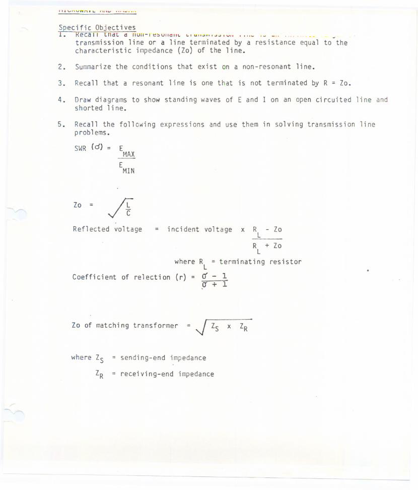
5. Recall the following expressions and use them in solving transmission line
p rob 1 ems.
SWR (d) = Et~AX
EMIN
Zo = fiReflected voltage = incident voltage x RL
RL
= terminating
Zo
+ Zo
resistor.
Coefficient of relection
where RL
(r) = rrcr
1+ I
Zo of matching transformer = ~ Zs x ZR
where Zs = sending-end impedance
ZR = receiving-end impedance
- - - - - - - -- ------
MICROWAVEAND RADAR 4
Specific Objectives
BLOCK1 - Waveguides Topic 2
1. Summarize the advantages and disadvantages of waveguides over coax lines.
2. Recall that energy propogates along a waveguide in the form of electrostaticand magnetic fields.
3. Recall the following conditions necessary for the propogation of energy in awaveguide:
a) Wavefronts are reflected at the interior wall of the waveguide and thatthe reflected angle is equal to the incident angle.
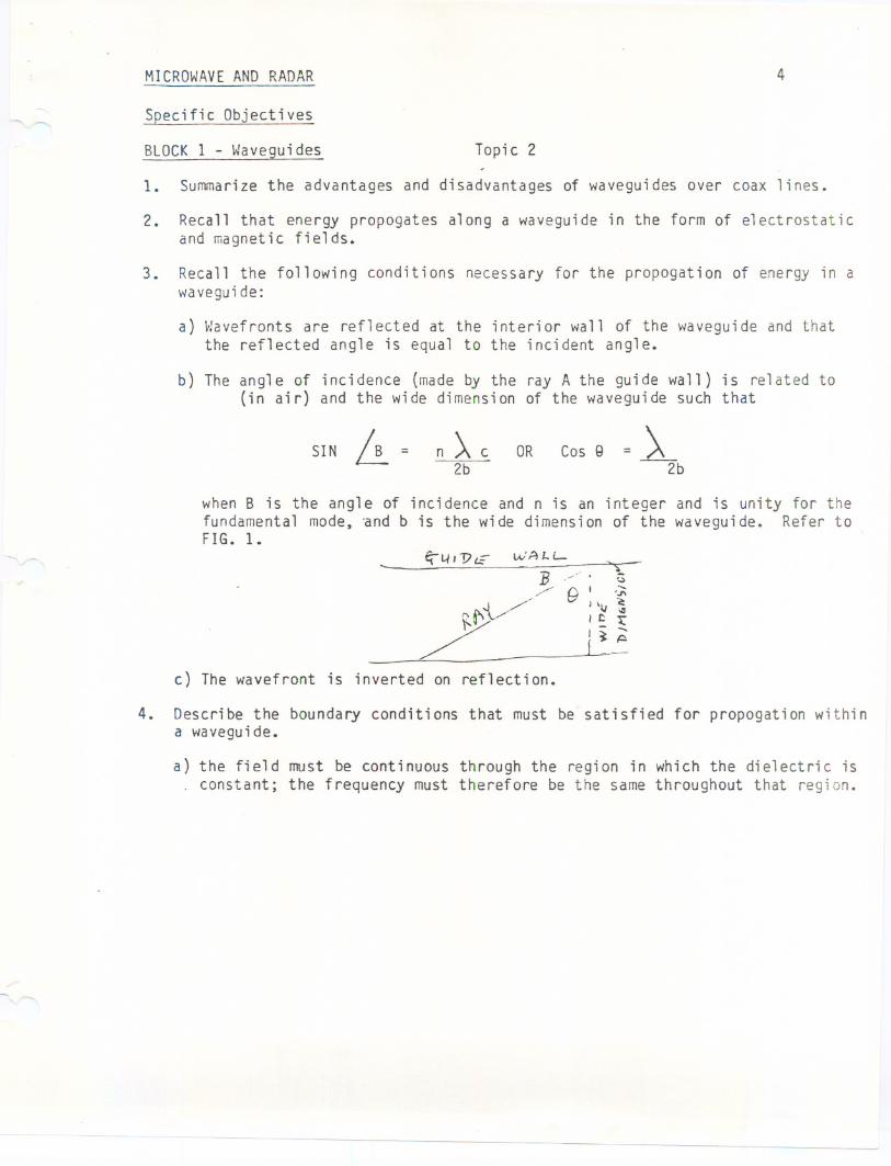
b) The angle of incidence (made by the ray A the guide wall) is related to(in air) and the wide dimension of the waveguide such that
SIN ~ = n ~ c2b
OR Cos Q = ~~b
when B is the angle of incidence and n is an integer and is unity for thefundamental mode, and b is the wide dimension of the waveguide. Refer toFIG. 1. -
c) The wavefront is inverted on reflection.
4. Describe the boundary conditions that must be satisfied for propogation withina waveguide.
a) the field must be continuous through the region in which the dielectric isconstant; the frequency must therefore be the same throughout that region.
---- - - ----
MICROWAVEANDRADAR 5
Specific Objectives
BLOCK1 - Waveguides Topi-c 2 continued
4. b) the electrostatic field is always perpendicular to the surface on which itacts: at the waveguide wall there is no component of the electrostaticfield parallel to the wall.
c) the electrostatic and magnetic fields are perpendicular to each other.
5. Recall that the cut-off frequency ~ c is that frequency for which Sin B isunity, that is when
.A a = 2b
6. Recall that the guide wavelength A g = A c and ~ g is thereforegreater than A a. Cc<s 8
7. calculate)\ g and )\ c when guide dimensions and frequency are known.
8. Recall the system of mode identification for rectangular and circularwaveguides.
9. Reproduce from memory drawings to illustrate the dominant mode in:
a) rectangularb) circular waveguides
10. Describe in qualitative terms, group and phase velocities, and calculatetheir values when given the information to determine ~ B in #3 above. OR
~e11. Describe in qualitative terms, methods of coupling energy into and out of
waveguides [probe, loop, aperture].
12. Reproduce from memory drawings to illustrate methods of achieving impedancematching in waveguides:
StubsPart i t i OI'lSFlared sections
transformertuning slugs
13. Recall the constraints on twists and bends.
- -
MI~ROWAVEANDRADAR 6
Specific Objectives
BLOCK 1 - Waveguides Topic 2 continued
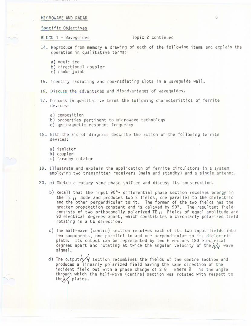
14. Reproduce from memory a drawing of each of the following items and explain theoperation in qualitative terms:
a) ma9i c teeb) directional couplerc) choke joint
15. Identify radiating and non-radiating slots in a waveguide wall.
16. Discuss the advantages and disadvantages of waveguides.
17. Discuss in qualitative terms the following characteristics of ferritedevices:
a) composit ionb) properties pertinent to microwave technologyc) gyromagnetic resonant frequency
18. With the aid of diagrams describe the action of the following ferritedevices:
a) isolatorb) couplerc) faraday rotator
19. Illustrate and explain the application of ferrite circulators in a systememploying two transmitter receivers (main and standby) and a single antenna.
20. a) Sketch a rotary vane phase shifter and discuss its construction.
b) Recall that the input 90°- differential phase section receives energy inthe TE II mod~ and produces two E fi elds, one para 11e1 to the di elect ri cand the other perpendicular to it. The former of the two fields has thegreater propagation constant and is delayed by 90°. The resultant fieldconsists of two orthogonally polarized TE" Fields of equal amplitude and90 e1ectical degrees apart, which constitutes a circularly polarized field
-rotating in a CWdirection.
c) The half-wave (centre) section resolves each of its two input fields intotwo components, one parallel to and one perpendicular to its dielectricplate. Its output can be represented by two E vectors 180 electricald:grees apart and rotating at twice the angular velocity of the~1{ waveslgnal.
d) The outPut~ section recombines the fields of the centre section andproduces a linearly polarized field having the same direction of theincident field but with a phase change of 2 e where 8 is the anglethrough which the half-wave (centre) section was rotated with respect to
the~ plates.
- - -
MICROWAVESOURCES(vacuum tube) 7
Specific Objectives
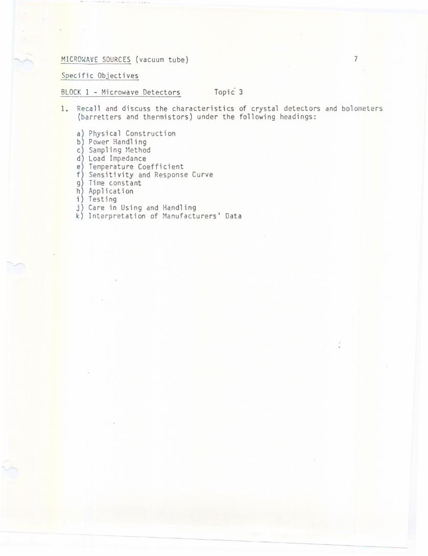
BLOCK1 - Microwave Detectors Topi C 3
1. Recall and discuss the characteristics of crystal detectors and bolometers(barretters and thermistors) under the following headings:
a} Physical Constructionb} Power Handlingc} Sampling Methodd} Load Impedancee} Temperature Coefficientf} Sensitivity and Response Curveg} Time constanth} Applicationi} Testingj} Care in Using and Handlingk} Interpretation of Manufacturers' Data
- --------- --- ----
MICROWAVESOURCES(vacuum tube) 8
Specific Objectives
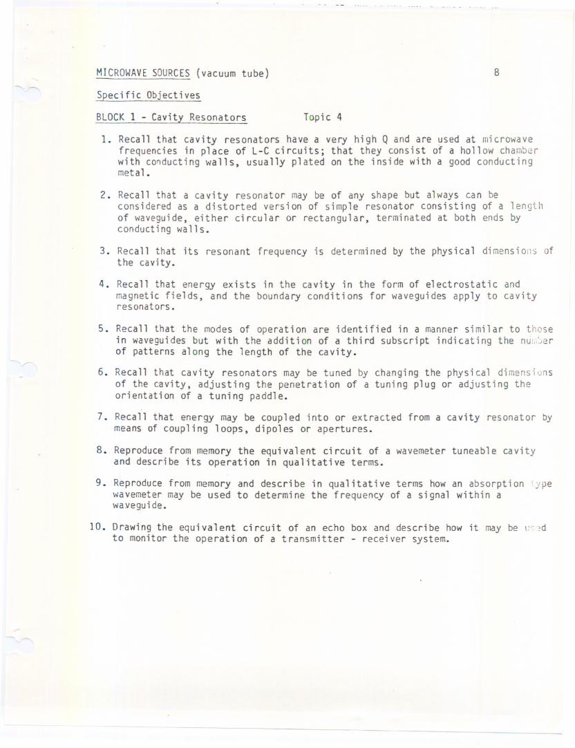
BLOCK1 - Cavity Resonators Topic 4
1. Recall that cavity resonators have a very high Q and are used at microwavefrequencies in place of L-C circuits; that they consist of a hollow chamberwith co~ducting walls, usually plated on the inside with a good conductingmetal.
2. Recall that a cavity resonator may be of any shape but always can beconsidered as a distorted version of simple resonator consisting of aof waveguide, either circular or rectangular, terminated at both endsconducting walls.
lengthby
3. Recall that its resonant frequency is determined by the physical dimensions ofthe cavity.
4. Recall that energy exists in the cavity in the form of electrostatic andmagnetic fields, and the boundary conditions for waveguides apply to cavityresonators.
5. Recall that the modes of operation are identified in a manner similar to thosein waveguides but with the addition of a third subscript indicating the nu:,,:)erof patterns along the length of the cavity.
6. Recall that cavity resonators may be tuned by changing the physical dimensionsof the c~vity, adjusting the penetration of a tuning plug or adjusting theorientation of a tuning paddle.
7. Recall that energy may be coupled into or extracted from a cavity resonator bymeans of coupling loops, dipoles or apertures.
8. Reproduce from memory the equivalent ci rcuit of a wavemeter tuneable cavityand describe its operation in qualitative terms.
9. Reproduce from memory and describe in qualitative terms how an absorption lypewavemeter may be used to determine the frequency of a signal within awayeguide.
10. Drawi ng the equi va 1ent ci rcuit of an echo box and descri be how it may be L'" ~dto monitor the operation of a transmitter - receiver system.
- -- -- -- - - - --- - - ---
MICROWAVESOURCES(vacuum tube) 9
Specific Objectives
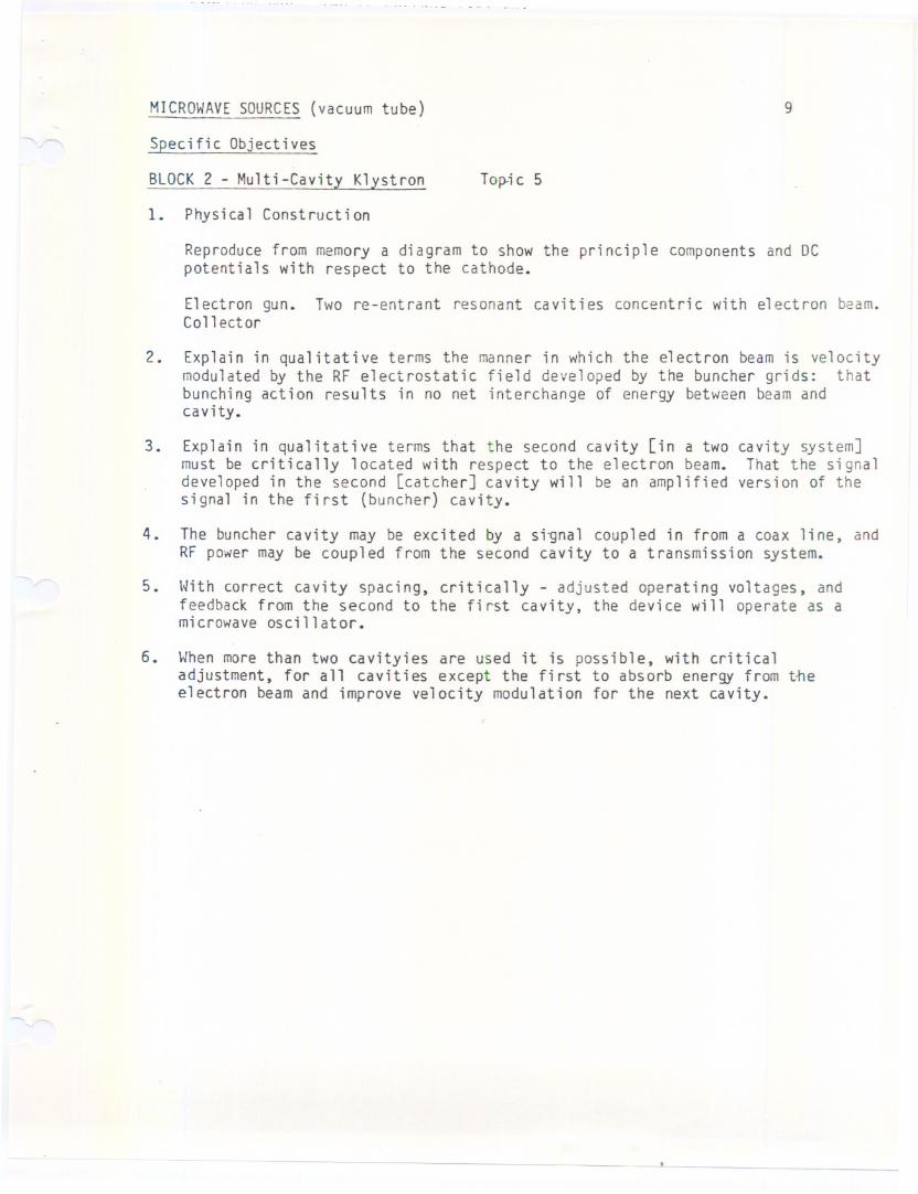
BLOCK2 - Multi-Cavity Klystron Top.ic 5
1. Physical Construction
Reproduce from memory a diagram to show the principle components and DCpotentials with respect to the cathode.
E1ectron gun. Two re-ent rant resonant ca vit i es concentri c with e1ectron beam.Collector
2. Explain in qualitative terms the manner in which the electron beam is velocitymodulated by the RF electrostatic field developed by the buncher grids: thatbunching action results in no net interchange of energy between beam andcavity.
3. Explain in qualitative terms that the second cavity [in a twomust be critically located with respect to the electron beam.developed in the second [catcher] cavity will be an amplifiedsignal in the first (buncher) cavity.
cavity system]That the signa 1
vers i on of the
4. The buncher cavity may be excited by a si~na1 coupled in from a coax line, andRF power may be coupled from the second cavity to a transmission system.
5. With correct cavity spacing, critically - adjusted operating voltages, andfeedback from the second to the first cavity, the device will operate as amicrowave oscillator.
6. When more than two cavityies are used it is possible, with criticaladjustment, for all cavities except the first to absorb energy from t~eelectron beam and improve velocity modulation for the next cavity.
- - - .1 _ - --
MICROWAVESOURCES(vacuum tubes) 10
Specific Objectives
BLOCK2 - Reflex Klystron Topic 5
1. Reproduce from memory, a diagram showing the principle componentsgun, cavity-grid assembly and repeller). Include in this diagramDC voltages and explain why the tube must not be operated withoutpotential on the repeller.
(electronthe re 1at i ve- ve
2. Explain qualitatively the manner in which the electron beam is velocitymodulated.
3. Explain in qualitative terms how magnitude of repeller voltage determineselectron penetration of the drift space and thus adjusts the mode ofoscillation.
4. Describe in qualitative terms the different power and bandwidthcharacteristics of the three modes of opertion which are usually within therange of repeller control.
5. Ability to turn on and adjust the reflex klystron for opimum performance, atthe same time observing precautions for the safety of the klystron and theauxillary equipment. To this extend an ability to read and understand themanufacturer's specifications is essential.
6. Except for the energy that may be coupled in to the first cavity froman external source, all the energy extracted from a klystron is supplied bythe electron beam source.
-------
1. Define Multicavity velocity - modulated system employing a special diode. _ __DnwP[".flll._m_('1J'0t;c.~£iolrt__ .., ,,, "" t"'J _".".J U twIVII VI U
multi cavity electron resonance megnetron.
3. Describe in qualitative terms how the combined electrostatic and magneticfields can be adjusted to produce the spiraling electron paths required foroscillation.
4. Recall that RF energy can be extracted from one of the cavities for couplirto the transmission system; and that the source of this energy is the electbeam supply.
5. Recall that the desired mode is 1800 phase shift between cavities and thatoperation in this mode is ensured by anode block strapping.
6. Recall that electron bombardment causes cathode heating and necessatatesreduction (or removal) of heater current when the magnetron is operating.
7. Understand the REIKE diagram to the extent that:
a) frequency "pulling" is maximumwhen the load is adjusted for maximumPOy
b) the load must be adjusted for minimum VSWR to minimize frequency pullin~
8. Recall that changing the position of the end plates effects the electron pcand is used to effect the resonant frequency of tunable magnetrons. Recallother methods of tuning - plug, vane.
9. Recall that magnetrons may be operated in a CWmode or may be modulated bypulses ranging from 10 KVto 50 KV.
10. With the aid of diagrams, describe the methods used to monitor magneticoperation:
a) cathode current metering
b) filament current metering
c) high voltage metering and control
d) output pOHer and frequency measurement
e) spectrum analysis
11. Recall the symptoms characteristic of arcing and the malfunctions that cancause arcing.
12. Recall the precautions to be observed in installing and seasoning (hardenina new magnetron.
-
MICROWAVESOURCES(vacuum tubes) 13
Specific Objectives
BLOCK 2 - Backward Wave Oscillator (B.W.O.) Topic 5
1. Draw a simple diagram to show the construction of a B.W.O.
2. Recall that the electron beam is a "Hollow Cylinder" passing close to thehelix turns and is focussed by a strong axial magnetic field which allowsmovement only in the direction of the axis of tube.
3. Recall that oscillation begins in the B.W.O. when a random variation in theelectron beam induces a wave in the helix winding, such a wave travellingbackward (towards the electron gun) causes velocity modulation of the electronbeam which results in bunching.
4. a) With the aid of a simple diagram explain how the "electronic fields"between three consecutive turns of the helix produces bunching.
b) Recall that the maximumcoupling between the helix wave and the gun occursmidway between turns and is minimum directly under the helix turns.
c) Recall that the phase relationship between the helix wave and the velocityof the electron beam is such that any specific portion of the beam will beaffected by.an electric field of the same phase as it passes successivegaps along the helix wave.
5. Recall that the average electron velocity of the beam is slightly greater thanthe effective velocity of the helix wave.
6. Recall. that the density of electron bunches increases according to a sinewaverelationship as the beam progresses towards the collector.
7. Recall that the helix wave moves toward the gun and gains amplitude in asinusoidal manner.
8. Recall that as the velocity of the electron beam is varied the phase delay ofeach regenerative (coupling loop between mid-turn points) will be changed.Provided that the beam current is great enough these loops will oscillate at afrequency such that the phase delay of each loop is equal to one cycle.
- - --- -- --- ----
MICROWAVESEMICONDUCTORDEVICES 14
Specific Objectives
BLOCK2 - Gunn Diode Topic 6
1. With the aid of a simple diagram describe the structure of a Gunn Diode.
2. Recall the "Gunneffect" - When the "DCbias across A gallium Arsenid~ sandwichis raised to A threshold value (approximately 3 KVper cm) oscillation in themicrowave region is produced.
3. Draw from memory a curve to show the typical current vs electric fieldcharacteristic of a Gunn Diode.
4. Recall that the curve may be accounted for as follows:
During the positive portion of the curve thecurrent increases as an increasing number ofvalence electrons pass into the normal (lower)conductionband. in this band electrons havelow energy and high velocity. At the thresholdvalue and during the negative resistancepart of the curve some electrons pass toa second conduction band where they havehigh energy and low velocity.
5. Recall that because electrons travel at different speeds in the negatiyeresistance region A bunching effect is produced. The bunching produces liEfield domains" which drift from the negative to the positive domain reachesthe positive terminal. and coincidently A new E domain forms at the cathode.
6. Draw from memory a simple diagram showing a Gunn Diode mounted in a tuneablecavity.
7. Reca11 that:
a) The frequency of the output is principally determined by the physicalthickness of the wufer.
b) There are several techniques which can be used to tune a Gunn DeviceOscillator:-
Bias ControlMechanical tuning of the resonant cavityVariable permeability (ferrite)Varactor tuningYIG spheres
c) Bias control tuning is usually unsatisfactory because the degree offrequenet variation and its sign will vary from one device to another.
d) There will be a considerable variation in output power with frequency.
e) The device most commonly used for electronic tuning is the varactor.
f) Gunn Diodes are available for operation in the S. J and Q bands.
g) Typical operation is from a stable D.C. source between 6 and 12 V at 100 -200 M.A.
- -- --
Specific Objectives
I.--nj IYPlcal power output lies between 2 and 20 MWat specified frequencies.
8. Recall that the extremely fast switching characteristic (ns) allows generati,of extremely short pulses (3 ns) and therefore extremely accurate distancemeasurement.
9. Recall that doppler mode operation of the Gunn Diode permits detection of ve,slight movement, even normal breathing, in an area under surveillance.Doppler measurement to within 0.15 metres an application is the high precisicdocking of Super - Tankers.
- -- -- - - --
MICROWAVEMEASUREMENT 17
Specific Objectives
BLOCK 3 Topic 7
1. Given: the HP microwave laboratory equipment
an SWR meter
and RF power meter
an oscilloscope
assemble a waveguide circuit and perform the following operations:
A. adjust the klystron for optimum operation at a stipulated frequency.
B. measure the VSWR of the system.
C. adjust the system for minimum VSWR.
D. measure the power in the waveguide.
E. determine the attenuation of microwave components.
F. with the aid of a Smith chart determine the impedance of a given load.
2. Draw a functional block diagram of the following test equipment and explainthe purpose of each block.
A. SWR meter
B. Power meter
3. Draw a functional block diagram of the klystron power supply and explain thepurpose and opertion of the protection circuits.
4. Using the equipments listed above investigate the characteristics of a GunnDiode Oscillator.
- --
Specific Objectives - Smith Chart.1. \JIVt::11 Lilt:: 4UOUI OLUIt:: \..VII'f.lVIICIIL;) VI a Ivau allu LIIC l-V VI a .1.1 all::>IIII;);)IVII 1111<:;
determine the normalized impedance of the load.
2. Given the normalized impedance of a load, use the Smith chart to determine:
a) SWRon a transmission line
b) Impedance at some specified point on the transmission line
3. Using the Hewlett-Packard micorwave laborato~ equipment the SWRmeter and th1Smith chart IIdetermine the impedance of a given load" device.
- ----
._-
RADARPRINCIPLES 19
Specific Objectives
BLOCK 4 Topics 8 & 9
1. Recall that there are three methods used for detection by radar:
Continuous wave (CW)Frequency modulation (FM)Pulse modulation (PM)
2. Recall that the CWmethod makes use of the DOPPLEReffect.
3. Explain the Doppler effect in qualitative terms and recall that
Doppler frequency (fd) = 2 ft Vrc
where ft =Vr =c =
transmitter frequencytarget radial velocityspeed of light
4. Recall that the CWmethod is most effective with targets having a high radialvelocity. The difference frequency (ft - fd) is used to determine presenceand speed of a moving target.
5. Recall that in the FMmethod the transmitter frequecny is varied continuouslyand at a preceise rate over Q specified frequency band. The frequency of areceived signal is compared with the instantaneous transmitter frequency. Thedifference between the two frequencies depends on the distance travelled bythe reflected signal and is used as a measure of range.
6. Recall that in the FM method the Doppler effect causes range inaccuracy in thecase of ~oving targets and this method is therefore less effective withtargets whose radial velocity is high.
7. Recall that in the PMmethod energy is transmitted in short pulses; 0.1 - 50micro-secs. and that range is determined on the basis of the travelling timeof. reflected signals.
8. Recall that the speed of radio waves is 6.18 micro-secs. per nautical mile(NM)and the return time of a received signal is therefore 12.36 micro-sees.per NM.
9. Reproduce from memory drawings to illustrate "A", "B", PPI (C) and D typepresentat ions.
- ---
RADARPRINCIPLES 20
Specific Objectives
BLOCK4 Topics 8 & 9 continued
10. Recall that accuracy of range measurement is effected by the sharpness of theleading edge of the pulse together with the ability to time the arrival of theleading edge.
11. Describe in qualitative terms how range resolution (discrimination) andminimum range are effected by the duration of the pulse.
12. Recall that radar maximum range is determined by:
Tx power outputReceiver sensitivityPulse recurrence frequency (PFR)
13. Explain in qualitative terms how the antenna beam width effects the accuracyof determining agimuth end elevation angles and angular resolution(discrimination).
14. a) With the aid of diagrams, explain how the polar co-ordinates (Slant Range,Azimuth and Elevation) may be converted to rectangular co-ordinates.
b) Explain how processing of rectangular co-ordinates permits prediction offuture position of the "Radar Target".
15. With the aid of diagrams, describe the role and characteristics of:
Track i ng radarsSearch radarsHeight finder radarsBeacon (IFF) radars
16. Reproduce from r.€mory a functional block diagram of a pulsed radar and explainthe function of each block.
17. Recall that the relationship between transmitter average power and peak poweris gi~en by:
Average PowerPeak Power
= Pulse widthPulse repetition time
18. Recall that the duty cycle = pulse widthpulse repetition time
- - - --- - - --- - - -
RADARPRINCIPLES 21
Specific Objectives
BLOCK 4 Topics 8 & 9 continued
19. Given the radar equation below qua1itatively. explain each of its terms.
Rr~ax = 127TT 4/ (PtT) x (L-)
Wrr.1in
x
20. With the aid of functional block diagrams. describe the operation of:
A. FM type ra da rB. CWtype rada r
21. Recall the reasons for using a duplexer in a transmission line system.
22. With the aid of simple diagrams. describe the operation of a duplexer in awaveguide system.
23. Recall that an artificial line may be used to accomplish the following tasks:
A. Develop a rectangular pulseB. Effect a time delayC. Store energy
describe the charging of an artificial line
25. With the aid of simple diagrams describe D.C. resonant charging of a pulseforming network and explain the purpose of a "hold-off" diode.
26. A. -Illustrate and describe the technique of binary integration of raaarreceiver signals.
B. ~ith the aid of block diagrams and other illustrations. describe how eachquantized signal (video hit) is stored in the appropriate range bin(usually i mile) of memory. together with other pertinent information suchas azimuth and altitude.
C. Recall that storing hits from several previous sweeps allows processing ofdata covering the width and range of the antenna beam pattern.
D. With the aid of illustrations explain how the sliding window allowsmonitoring of hit history during each range cell period.
24. With the aid of simple drawingsunder the following condition.
A. Zo = Z source
B. Zo Z source
C. Zo Z source
RADARPRINCIPLES 22
Specific Objectives
BLOCK4 Topics 8 & 9 continued
26. E. Recall that when a valid target ~s identified a synthetic signal isproduced for display on a random access plan position indicator (rappi)Itthe appropriate range and azimuth. The symbol indicates which types ofradar identified the target and the system may provide further informationsuch as flight number, altitude, etc. on request.
F. With the aid of illustrations describe the statistical analysis ofquantized radar video under the following headings:
A) Hits per ScanB) Beam Splitting for Azimuth DeterminationC) Probability of False AlarmD) Adjustment of False Alarm RateE) Automatic Clutter Elimination (ACE)
RADAR PRINCIPLES 23
Specific Objectives
BLOCK5 Topic 10
DECCAMARINERADAR0202
1. Draw a block diagram of the 0202 radar; name the blocks and signals, anddescribe the operation at this level.
2. Given the detailed schematic diagrams explain the operation of any section ofthe system illustrating with waveforms as necessary.
3. Perform the tests and adjustments contained in the service manual.
4. Demonstrate the ability to troubleshoot the system and isolate failedcomponents.
5. Conduct performance tests of TH transmitter and transmission system.
MICROWAVE& RADARlABS 24
lab Experiments 1 to 8 -- Refer to Hewlett-Packard Microwave lab Manual
lAB EXPERIMENT#9
1. Determine the impedance of the Horn Antenna
2. Use a Slide-Screw Tuner to achieve min. swr.
3. Determine: Power RadiatedPower Refl ected
4. Develop a system to plot the radiation pattern of the Horn Antenna.
lAB EXPERIMENT#10
Investigate the characteristics of a Gunn Diode.
-- -- - - -