SatBm Operators Manual D
144
Saturn Bm Marine Class 2 Operator’s Manual
-
Upload
karst-van-der-lei -
Category
Documents
-
view
153 -
download
5
Transcript of SatBm Operators Manual D

Saturn Bm MarineClass 2Operator’s Manual

SATURN B – TELEPHONE DISTRESS CALL
DISTRESSSaturn B
ALARMACKNOWLEDGE
DISTRESSBUTTON
ACKNOWLEDGEPUSH BUTTONALARM INDIC ATORALARM BUZZER
Indicator flashes slowly, then quickly after 6 seconds
Reception:
Transmission:
TRANSMISSION1 Lift telephone handset h.2 Lift flap over DISTRESS BUTTON.
Press and hold downDISTRESS BUTTON forat least 6 seconds .
3 Wait for dialling tone.
4 Press ?-key to initiateyour call. You can alsoselect LES: e.g. 4+?
5 When the Rescue Co-ordination Centre (RCC) Operator answers, speak clearly, and give the following message:• MAYDAY MAYDAY MAYDAY• THIS IS (ship’s name and identity) CALLING ON INMARSAT FROM
POSITION (latitude and longitude, or relative to a point of land).• MY INMARSAT MOBILE NUMBER IS (IMN for the Saturn Bm telephone you
are calling from) USING THE (Ocean Region) SATELLITE .• MY COURSE AND SPEED ARE (course and speed).• NATURE OF YOUR DISTRESS, for example:
> Fire/explosion > Listing > Abandoning ship> Flooding > Sinking > Piracy attack> Collision > Disabled > Medical service> Grounding and adrift required
• ASSISTANCE YOU REQUIRE.• OTHER INFORMATION to help rescue units.End your message by saying "OVER", which is the invitation for the RCC to reply.
6 Follow the instructions from the RCC Operator, and when requested, replace thehandset to await further calls.
7 Keep the telephone line clear so that the RCC can call you back when necessary.
RECEPTION• The ALARM BUZZER and ALARM INDICATOR are activated on all installed
Distress Alarms when a distress call is received.• When answering the call, ALARM BUZZERS stop and ALAR M INDICATORS light
steadily on all Distress Alarms.• Pressing the ACKNOWLEDGE PUSH BUTTON where the telephone rings, stops buzzers
on all Distress Alarms. Pressing the button at other sites only stops the buzzer locally.
Doc. No. QLZB911014 Rev. A Infotema 5147 11/95
Note! For further information on:• Detailed operation, see "Distress Alarm ".• Distress Alarm setup, see "Configuring Ports ".• Preferred Distress Land Earth Station, see "Selecting Default Distress LES ".• To check the operation of the Distress Alarm, see "Distress Test ".

1. Getting Started
2. Operation
3. Configuration
4. System
5. Appendices
* F
unct
ions
mar
ked
with
a s
tar
are
only
acc
essi
ble
whe
n S
atur
n B
is s
et in
OP
ER
AT
OR
LE
VE
L. S
ee "
Set
ting
Use
r Le
vel"
in c
hapt
er 2
. Ope
ratio
n.
Chapter 1. Getting StartedIntroduction ................................................................ 1.1Handset w/Display & Keypads ................................... 1.6Starting Up ................................................................. 1.7Call from Display Handset ....................................... 1.10Call from Telephone ................................................. 1.11Service Address Calls .............................................. 1.12Terrestrial Network and Priority Calls ...................... 1.13Using Telefax ........................................................... 1.14Connector Panel ...................................................... 1.15
Chapter 2. OperationUsing the Display Handset ......................................... 2.1Functions ................................................................... 2.5Selecting Ocean Region ............................................ 2.8Short Numbers ........................................................... 2.9Last Number Redialing ............................................ 2.12Active Alarms ........................................................... 2.13Info Log .................................................................... 2.14Clear Cause Log * .................................................... 2.15Terminal Status * ..................................................... 2.16Setting User Level .................................................... 2.17Selecting Default LES .............................................. 2.18System Information * ................................................ 2.19Group Calls * ............................................................ 2.20Geographic Position * .............................................. 2.21Satellite Search * ..................................................... 2.22Heading Input * ........................................................ 2.26Antenna Azimuth Limit ............................................. 2.27Manual Antenna Pointing * ...................................... 2.28Message Indicator .................................................... 2.30Distress Alarm .......................................................... 2.31
Chapter 3. ConfigurationSetting Display Contrast * .......................................... 3.1Setting Ringing Volume * ........................................... 3.2Setting Date and Time * ............................................. 3.3Area Group Calls * ..................................................... 3.4LES Capabilities * ...................................................... 3.5Selecting Stand-alone LES * ...................................... 3.6Selecting Default Distress LES * ................................ 3.7Distress Test * ............................................................ 3.8Compass Type * ........................................................ 3.9Antenna Configuration * ........................................... 3.10Configuring Ports * ................................................... 3.11Incoming Call Route * .............................................. 3.15Various Configurations * .......................................... 3.21Printout of Lists and Settings * ................................. 3.22
Chapter 4. SystemDescription ................................................................. 4.1Communication .......................................................... 4.3Antenna Pointing ........................................................ 4.8Satellite Searching ................................................... 4.10
Chapter 5. Appendices / IndexAppendix A
Satellite Coverage Map ........................... A-1List of Land Earth Stations ...................... A-2Azimuth Map ........................................... A-4Elevation Map ......................................... A-5NAVAREA Codes .................................... A-6
Appendix BTelephone Country Codes ...................... B-1Service Address Codes ........................... B-5
Appendix CCabling Diagram ..................................... C-1
Appendix DList of Alarm Messages ........................... D-1List of Start-up Messages ....................... D-5List of Terminal Status Messages ........... D-6
Appendix EHandset Functions .................................. E-1
Appendix FConfiguration Tables ................................ F-1
Appendix GList of Terms ............................................ G-1
Appendix HMCU Maintenance .................................. H-1
Saturn Bm Marine – Operator’s ManualDoc. No. QLZB911020 Rev. D Copytema 12/97

Saturn Bm – Operator’s Manual
This manual complies with MCU software version no. 5.XX.

Saturn Bm Marine – Operator’s Manual
Contents Chapter 1. Getting Started
Introduction ................................................................................. 1.1Handset w/Display & Keypads ................................................... 1.6Starting Up.................................................................................. 1.7Call from Display Handset ........................................................ 1.10Call from Telephone ................................................................. 1.11Service Address Calls .............................................................. 1.12Terrestrial Network and Priority Calls ....................................... 1.13Using Telefax............................................................................ 1.14Connector Panel ....................................................................... 1.15
GE
TTIN
G S
TAR
TED
Nera SatCom AS reserves the right to change the designand specifications of the equipment without notice.


Saturn Bm – Chapter 1. Getting Started 1.1
Intr
od
uct
ion
Introduction
Chapter 1. Getting Started
GeneralSaturn Bm Marine is an Inmarsat-B terminal providing access to theinternational terrestrial telephone network providing telephone, dataand telefax service.
See chapter 4. System for an overview of satellite communicationsand the Inmarsat-B system.
The figure below shows the basic parts of a Below Deck Equipmentinstallation.
Figure 1.1 Example ofBDE installation.
Display
Handset
Telefax (option)
Main ControlUnit(recommendedmounting)
PowerSupply
DistressAlarm
Telephone
DistressAlarm
MessageIndicator
PC(option)
InterfaceBox
Remote installation(options)
RF
-Cab
le (
to A
nten
na)
Printer(option)
Message Indicator
N
SATURN B
DATA MESSAGE
TELEX MESSAGE
FAX MESSAGE
RESET
DISTRESS INMARSAT B
DISTRESS INMARSAT B
Saturn M

Saturn Bm – Chapter 1. Getting Started1.2
Intr
oduc
tion
Con
t’dIntroduction Cont’d
Below Deck Equipment - BDE
Main Control Unit
The Saturn Bm Main Control Unit (MCU) - which constitutes themajor electronic part - is designed for wall or desktop installation. TheMCU power requirement is 150 W at 11 - 34 VDC.
Display Handset
The Display Handset keypad and built-in display allows dialing andalphanumeric editing for communication and system control.
Distress Alarm
The Distress Alarm provides activation and indication of an alerttransmission.
Power Supply
220 VAC to 28 VDC with battery backup of MCU (including ACU andRF units).
Displayhandset Main Control Unit – MCU
Gyrointerface
7
4
13
6
9
DEL
2
5
8
0
DIAL 00+INTLTEL.NO.+
ONSHIFT
Basic Equipment
Optional Equipment
Telephones(wall or desk)
Distress Alarm Power Supply
PC (Data)MessageIndicator
Message Indicator SATURN B
DATA MESSAGETELEX MESSAGE
FAX MESSAGE
RESET
Power Supply(Battery backup of
MCU,PC and Printer)PC (Telex) Printer
Telefax(replacing atelephone)
DISTRESSSaturn B
ALARMACKNOWLEDGE

Saturn Bm – Chapter 1. Getting Started 1.3
Intr
oduc
tion
Con
t’dIntroduction Cont’d
Above Deck Equipment - ADE
The Saturn Bm Above DeckEquipment consists of:
• Stabilized Antenna withRF Units andAntenna Control Unit, ACU
• Radome
The stabilized antenna ismounted on the Azimuth Post.
The ADE should be separatedas far as possible from the HFantenna, and preferably by atleast 5 m from the antennas ofother communication ornavigation equipment.
Optional Equipment
• DTMF telephones (max 5)
• Telefax (for connection to a telephone port)
• Message Indicator, activated on reception of telex, telefax or datatraffic.
• PC (Telex)
• PC (Data)
• Serial printer
Radome
AntennaDish
RF-Units
AzimuthPost
AccessHatch
AntennaControlUnit
StabilizedAntenna
Saturn Bm – Chapter 1. Getting Started1.4
Intr
oduc
tion
Con
t’d Introduction Cont’d
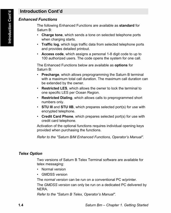
Enhanced Functions
The following Enhanced Functions are available as standard forSaturn B:• Charge tone, which sends a tone on selected telephone ports
when charging starts.• Traffic log, which logs traffic data from selected telephone ports
and provides detailed printout.
• Access code, which assigns a personal 1-8 digit code to up to100 authorized users. The code opens the system for one call.
The Enhanced Functions below are available as options forSaturn B:
• Precharge, which allows preprogramming the Saturn B terminalwith a maximum total call duration. The maximum call duration canbe extended by the owner.
• Restricted LES, which allows the owner to lock the terminal toone specific LES per Ocean Region.
• Restricted Dialing, which allows calls to preprogrammed shortnumbers only.
• STU III and STU IIB, which prepares selected port(s) for use withencrypted telephone.
• Credit Card Phone, which prepares selected port(s) for use withcredit card telephone.
Activation of the optional functions requires individual opening keysprovided when purchasing the functions.
Refer to the "Saturn B/M Enhanced Functions, Operator’s Manual".
Telex Option
Two versions of Saturn B Telex Terminal software are available fortelex messaging:
• Normal version
• GMDSS version
The normal version can be run on a conventional PC w/printer.
The GMDSS version can only be run on a dedicated PC delivered byNERA.
Refer to the "Saturn B Telex, Operator’s Manual".

Saturn Bm – Chapter 1. Getting Started 1.5
Saturn B Data Service
The Asynchronous Data Service (ASD) offers data transmission at9.6 kbps via the built-in modem feature of the Saturn B terminal.Only modem communication software needs to be installed in theassociated PC to allow data transfer.
The Asynchronous Data Service is provided as standard feature.
The optional High Speed Data Service (HSD) service offers a56/64 kbit/s full duplex link with a terrestrial ISDN network:• High speed data transfer, connection to data networks
• Video transfer, compressed store-and-forward transmission
• Video phone with hotline facility
• Multichannel audio transmission
• Multiplexed data, facsimile and voice.
With the optional Datacom Switch Unit (DSU) it is possible to haveHSD and ASD equipment connected at the same time.
Intr
oduc
tion
Con
t’dIntroduction Cont’d

Saturn Bm – Chapter 1. Getting Started1.6
Figure 1.2 Keys and indicatorson Display Handset.
Note!The terms Mobile Earth Station (MES) andLand Earth Station (LES) are sometimesreferred to as Ship Earth Station (SES) andCoast Earth Station (CES) respectively.
Han
dse
t w
/Dis
pla
y&
Key
pad
1 3
4 5 6
7 8 9
0
ABC 2 DEF
DATA
GHI
JKL MNO PQR
STU VWXTAX LIGHT
YZÆ
SPCØÅ.
PLAY
ÄÖÜ
ESC DEL
ON/OFFLIST
LIST
FUNC ALPHA ENTER
SHIFT MORE/HELP
LESPTT
ON
SHIFT BATALPHA
DIAL 00+INTLTEL.NO.+
Handsfreemicrophone
2 x 12 characteralphanumericalLCD display.
Auxiliary keys:Allows entering ofshort numbers,changing OceanRegion, selectingLand Earth Stationetc.
Number keys:Only the number keysare required to callthe end subscriber.Pressing ALPHAselects letter entries.Pressing SHIFTselects secondaryfunctions.
Handsfreeloudspeaker
Displayed when applicable:• at hook OFF• when additional info/help is
available.• when loudspeaker is ON.• when pressing SHIFT to use
secondary functions.• when pressing ALPHA to select
keypad letters.• during data calls.• when in contact with LES or NCS.• when receiving a call. Displayed
steadily during communication.• flashes when receiving important
information/alarms.• when power is turned ON.• 1 - 3 signal quality indicators.
Selects functions and displays HELPpage if any.Selects alphabetic key function
Moves to next choice, or entersselected one. Access to Active Alarmslist (SHIFT function).Selects secondary functions.
Displays additional information/help.
Direct access to Default LESselection, and Ocean Regionselection (SHIFT function).Push-To-Talk (PTT) when loud-speaker is operative.Turns internal loudspeaker ON/OFF.Switches between handsfree w/PTTand normal use.Not in use
Toggles hook switch, or reverts toprevious position
Deletes last character entry, orcomplete entry.
Steps down/up through functionmenu/choices.LIST scrolls through choices(SHIFT function).
FUNC
ALPHA
ENTER
SHIFT
MORE/HELP
LESPTT
ON/OFF
ESC
DEL
LIST
LIST
ON
SHIFT
ALPHA
Handset w/Display & Keypads
The figure below shows all keys and indicators required for full operation andcontrol of Saturn B.

Saturn Bm – Chapter 1. Getting Started 1.7
Starting Up
Switching ON
The POWER Switch on the back panel of the Main Control Unitswitches all basic units of the Saturn Bm terminal on/off:
• the Display Handset
• the Main Control Unit (MCU), and the Antenna Unit
See figure 1.3 for location of the POWER switch and POWER indicator.
For optional equipment, see their Operating Manuals.
The Saturn Bm should normally be switched ON at all times.
Switching ON initiates a self-test and an automatic satellite search(which may take a few minutes), causing the following messages tobe displayed:
The self-test should be ready within approximately one minute. If not,see list of "Startup messages" in Appendix D.
The Saturn Bm retains the gyro, azimuth and elevation data when theterminal is switched OFF. When switching ON, the antenna is auto-matically pointed in the same direction it had before switching OFF.
When switching ON Saturn Bm for the first time, the following must beentered/selected:
• Ship’s heading, see next page.
• Ocean Region, see next page.
• Default Distress LES,see "Selecting Default Distress LES" in chapter 3. Configuration.
• Distress Alarm address,see "Configuring Ports" in chapter 3. Configuration.
• Search for satellite must be initiated, see next page
During initializationand self-test: When ready:
During antennaauto search:
Whenswitching on:
DIAL 00+INTLTEL.NO.+
ON
PLEASE WAIT
ON
SYSTEMINITIALIZING
ON
SEARCHINGSATELLITE
ON
Sta
rtin
g U
p

Saturn Bm – Chapter 1. Getting Started1.8
Note! Entering gyro data and initiating a satellite search require thatthe Saturn Bm User Level is extended to "Operator Level", see "Set-ting User Level" in chapter 2. Operation.
Checking Heading DataCheck the current heading input:
• Select READ/SETfunction (29):
• Check setting:
• and revert to IDLE:
To update gyro input, see "HeadingInput" in chapter 2. Operation.
Ocean RegionCheck current selection:
and revert to IDLE:
To select another region, see"Selecting Ocean Region"in chapter 2. Operation.
Initiate Satellite SearchingStart a hemispheric scan for the selected satellite/Ocean Region:
• Select SEARCH FORSATELLITE function (26):
• Press ENTER as prompted toactivate the search function:
• Press ENTER again to actuallystart the satellite search:
• and revert to IDLE:
Note! The search may take a few minutes.
Starting Up Cont’dS
tart
ing
Up
Co
nt’
d
ENTER
ON
READ/SETCOMPASS29
ON
HEADING:275 DEG
9 LIGHT
YZÆ2 DEFPLAY
ESC3x
FUNC
ON
OCEAN REGIONIOR
3
LESPTTSHIFT
Ocean Region ref. no.
ESC
FUNC 6 PQR2 DEFPLAY
ON
SEARCH FORSATELLITE26
ON
PRESS ENTERTO SEARCH
ON
COMMANDACCEPTED
ENTER
ENTER
ESC2x

Saturn Bm – Chapter 1. Getting Started 1.9
Starting Up Cont’d
Signal Quality Indication
The signal quality indicators aredisplayed during communicationand signal strength readout:
1 - 3 asterisks – increasingquality of communication.No asterisks – call may bepossible, but uncertain.
Observing Signal Strength
Pressing SHIFT + 7 displaysthe signal strength:
Pressing MORE/HELP displaysthe "BER" value:The lower the value thebetter the signal quality.
Revert to IDLE:
Note!The signal strength reading (S/N=Signal/Noise ratio) will vary during acall.
The Bit Error Rate (BER) reading decreases as the quality of thereceived signal improves.
Sta
rtin
g U
p C
on
t’d
ON
DIAL 00+INTLTEL.NO.+
MORE/HELP
– – – –S/N: 254
ON
BER : 48SOUND OFF
SHIFT 7 STU
ON
Signal qualityindication
Not used inSaturn Mm/Bm
ESC

Saturn Bm – Chapter 1. Getting Started1.10
Call through Default LES
• Ready for operation:
To check the default LESin this Ocean Region:(To modify, see "Selecting Default LES"in chapter 2. Operation.)
1 Key in the internationalcall prefix 00:
2 Key in the country code,e.g. 47 (Norway):(See appendix B for list oftelephone country codes)
3 Key in subscribernumber:(within 45 seconds)
4 Initiate the call:Slow beeps are heard during call setup.The square indicator appears when LEShas accepted the call.Ringing tone is heard until answer.
5 Clear the call when finished:For short number and last numberdialing and other functions,see chapter 2. Operation.
Call through Selected LES
6 Enter the LES code:
Continue from step 1.(See appendix A for Satellite Coverage Mapand list of Land Earth Stations.)
Call
from
Dis
play
Han
dset Call from Display Handset
SPC
0 ÄÖÜ
7 STU4 JKL
0 ÄÖÜ
3 GHIDATA
ØÅ.
LESPTT
7 STU 2 DEFPLAY
7 STU
ON
IORLES 4 3
ON
LES 00400
ON
LES 0040047
4 JKL 0 ÄÖÜ0 ÄÖÜ
6 PQR 4 JKL
ON
LES 004004767244700
ON
ESC
ESC
ON
LES 003
DIAL 00+INTLTEL.NO.+
DIAL 00+INTLTEL.NO.+
ON

Saturn Bm – Chapter 1. Getting Started 1.11
General
A telephone is used for basic telephone calls. Control of functions andother facilities must be done from the Display Handset.
Call through Default LES
0 0 4 7 6 7 2 4 4 7 0 0 routes the call viathe default Land Earth Station for the Ocean Region you are operat-ing in.
Call through Selected LES
0 0 4 7 6 7 2 4 4 7 0 04 routes thecall via the Land Earth Station Eik (4) in Norway.
Last Number Redialing
0 retransmits the last number*.
Last Number Redialing through Selected LES
04 retransmits the last number via the selected LES
(Eik=4)*.
Short Number Dialing (Prefix 23)
2 3 1 5 fetches and sends the telephone number stored
under short number 15*.
Short Number Dialing (Prefix 23) through Selected LES
2 3 1 54 fetches and sends the telephone number
stored under short number 15 via the selected LES (Eik=4)*.
*Also applies when dialing from Display Handset.
Cal
l fro
m T
elep
honeCall from Telephone

Saturn Bm – Chapter 1. Getting Started1.12
General
The LESs support special information services accessible with 2-digitService Address Codes. See appendix B.
Example of obtaining assistance from the International Operatorwhere the default LES is situated:
Lift handset and dial: 1 1
Example of obtaining meterological information from a selected LES,e.g. Eik:
Lift handset and dial: 44 1
Note! Not all LESs provide every service listed. For more informationcontact technical assistance on 33 #.
Ser
vice
Add
ress
Cal
ls Service Address Calls

Saturn Bm – Chapter 1. Getting Started 1.13
Terr
estr
ial N
etw
ork
and
Prio
rity
Cal
lsTerrestrial Network
Dialing through terrestrial network is only possible using selectedLES.
The number may be in the range of 0 to 127.
Example of call through selected LES, e.g. Eik, and network 1:
0 0 4 7 6 7 2 4 4 7 0 014
LES NETWORK
Priority Calls
The following call priority levels are recognized by the Inmarsatsystem:
0 – Routine
1 – Safety
2 – Urgent
Saturn B normally transmits calls with priority 0: Routine.
Whether you are using the Display Handset or a telephone, dialing S1 or S 2 ahead of the ordinary call digits gives the call priority 1 or 2respectively.
Assignment of priority level is only possible using selected LES andselected network.
Example of priority 1 call through e.g. Eik:
0 0 4 7 6 7 2 4 4 7 0 011
LES NETWORK PRIORITY
4
Terrestrial Network and Priority Calls

Saturn Bm – Chapter 1. Getting Started1.14
General
Fax calls placed through the Saturn B are telefax only. Any telephonehandset connected to the telefax machine is for dialing purposes only.
To send a fax, use the same dialing sequence as when using atelephone, either through the default LES, or a selected one:see "Call from Telephone".
Telefax transmissions normally take 1.5 minute per standard textpage using standard resolution. Using superfine or halftone resolutionwill double the transmission time. Avoid using a separate cover page.The transmission rate is 9.6 kbps.
If a call failure should occur while sending a multi-page document, re-send only the failed pages.
Limitations
Saturn B is fully compatible with the world’s leading telefax machinesand telefax software standards. However, transmission may not bepossible through some of the telefax machines available on themarket. Please check with your agent before purchasing a telefax foruse with the Saturn B.
Usi
ng
Tel
efax
Using Telefax

Saturn Bm – Chapter 1. Getting Started 1.15
Connector Panel
Figure 1.3 MCU connector panel.
Co
nn
ecto
r P
anel
5 4 3 2 1
9 8 7 6 25 24 23 22 21 20 19 18 17 16 15 14
13 12 11 10 9 8 7 6 5 4 3 2 1
1 2 3 4 5
6 7 8 9
5 4 3 2 1
9 8 7 6
OFF++ [11 - 34 VDC] --
ON
HANDSET
EXT I/O GYRO NMEA-0183 DTE
TEL.1 TEL.2 TEL.3 TEL.4 TEL.5
AUX
PC PRINTER
Auxiliary
Telephone/telefax
Extensions
Telephone display handset
Gyro
Navigator NMEA-183
PC (control/telex)
Printer
PC (data)
Power
Antenna connector
Power ON/OFF
Power indicator
Saturn B
The figure below shows the location of the power ON/OFF switchand power indicator, as well as all connectors accessible on the rearpanel of the Main Control Unit (MCU).
For connections, refer to the Saturn Bm Installation Manual.


Contents
Saturn Bm – Operator’s Manual
OP
ER
AT
ION
Using the Display Handset ......................................................... 2.1Functions .................................................................................... 2.5Selecting Ocean Region ............................................................. 2.8Short Numbers ........................................................................... 2.9Last Number Redialing ............................................................. 2.12Active Alarms............................................................................ 2.13Info Log..................................................................................... 2.14Clear Cause Log * .................................................................... 2.15Terminal Status * ...................................................................... 2.16Setting User Level .................................................................... 2.17Selecting Default LES............................................................... 2.18System Information * ................................................................ 2.19Group Calls * ............................................................................ 2.20Geographic Position * ............................................................... 2.21Satellite Search * ...................................................................... 2.22Heading Input * ......................................................................... 2.26Antenna Azimuth Limit.............................................................. 2.27Manual Antenna Pointing * ....................................................... 2.28Message Indicator .................................................................... 2.30Distress Alarm .......................................................................... 2.31
* Functions marked with a star are only accessible whenSaturn Bm is set in OPERATOR LEVEL.See "Setting User Level".
Chapter 2. Operation
Nera SatCom AS reserves the right to change the designand specifications of the equipment without notice.

Saturn Bm – Chapter 2. Operation 2.1
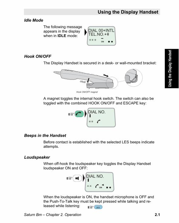
Idle Mode
The following messageappears in the displaywhen in IDLE mode:
Hook ON/OFF
The Display Handset is secured in a desk- or wall-mounted bracket:
A magnet toggles the internal hook switch. The switch can also betoggled with the combined HOOK ON/OFF and ESCAPE key:
Beeps in the Handset
Before contact is established with the selected LES beeps indicateattempts.
Loudspeaker
When off-hook the loudspeaker key toggles the Display Handsetloudspeaker ON and OFF:
When the loudspeaker is ON, the handset microphone is OFF andthe Push-To-Talk key must be kept pressed while talking and re-leased while listening:
Chapter 2. Operation
Using the Display Handset
Usin
g th
e Di
spla
y Ha
ndse
t
ESCDIAL NO.
LESPTT
DIAL NO.
ON
click!
Hook ON/OFF magnet
DIAL 00+INTLTEL.NO.+
ON

Saturn Bm – Chapter 2. Operation2.2
Using the Display Handset Cont’dUs
ing
the
Disp
lay
Hand
set
Volume Control
The received volume in the Display Handset may be adjusted during a call:
• Reducing the volume:
• Increasing the volume:
The volume is reset when clearing the call.
Light in Display and Keys
Illumination of the display and keys is turned on and off as follows:
Indicators on the Display Handset
flashes when receiving important information or an alarm.The indicator stops flashing once an alarm has been read:press SHIFT+ENTER, or see "Active Alarms".
flashes when receiving a call to Saturn B Display Handset.The indicator stops flashing when the call is established andremains displayed until the call is cleared.
displayed steadily as long as Saturn B remains synchronizedwith the Land Earth Station (LES), or Network CoordinatingStation (NCS). The indicator flashes slowly when no one istalking from the remote end during a call.
SHIFT or ALPHA
The functions marked red on the keypad may only be activated whenthe SHIFT indicator is displayed.
The keypad letters may only be activated when the ALPHA indicatoris displayed.
SHIFT and/or ALPHA are automatically deactivated when reverting toIDLE mode.
LIST
LIST
SHIFT 9 LIGHT
YZÆ
DIAL 00+INTLTEL.NO.+
ON
SHIFT ALPHA
SHIFT
ALPHA

Saturn Bm – Chapter 2. Operation 2.3
Using the Display Handset Cont’d
Usin
g th
e Di
spla
y Ha
ndse
t
Moving about in the Display
To scroll up/down throughfunctions or choices:
To move to next choiceor enter the selected one:
To move back to previousposition or display:
Note! Entered changesare lost when pressing ESCAPE.
Keying Letters
The letters on the keys are accessible when having pressed theALPHA key. Each key carries several letters that are entered succes-sively as follows:
• Set keypad inalphanumeric state:
• Press and hold therequired key until thewanted letter appearsin the display:
Deleting an Entry
To delete entry (to theleft of the cursor):
Service Dialing (During Call Only)
The Display Handset can be used for keying in the numbers for e.g.bank services, voice letters etc., using tone signalling (DTMF).
Before keying in the numbers required by the service, press:
Note! Service dialing isnot supported by all LESs.
LIST
LIST
ENTER
ESC
1 ABC
1 ABC
1 ABC
ALPHA
DEL
SHIFT 0 ÄÖÜ

Saturn Bm – Chapter 2. Operation2.4
Using the Display Handset Cont’dUs
ing
the
Disp
lay
Hand
set
Call Duration
The duration of a call as it proceeds can be read in the display, aswell as the accumulated time of all calls.
Ongoing call duration:
(remains until next call)
Accumulated time:
(Reset with DEL key)
Call Clearing Messages
A clearing condition causes a brief message to be displayed alongwith a reference number.
Alarm Messages
An alarm causes the triangleindicator in the display to flash.To read the alarm message:
Scroll through additional alarms, if any:
Revert to IDLE:
Table with comments is provided in appendix D.
ENTER
LIST
LIST
Alarm indicator
SHIFTACU RAMFAILURE7
ON
ESC3x
SHIFT 8 VWXTAX
MORE/HELP
Hours:minutes:seconds ON
ON
THIS CALL0 : 12 : 33
TOTAL CALLS10 : 55 : 44

Saturn Bm – Chapter 2. Operation 2.5
Functions
General
The many functions available are explained throughout this chapter.
See list of functions in table 2.1, and appendix E.
Each menu and function is assigned a specific number.• A function may be selected directly
by its number, for exampleLAST NUMBER LIST (11):
or by searching withthe ARROW keys:
• For extended lines or help:
• For field description:
• To revert:
User Levels
The functions are accessible from the following levels, designated:• USER level, which includes basic functions such as short number
dialing, selecting Ocean Region etc.
• OPERATOR level (marked with stars in table 2.1), which addsmore advanced functions such as date & time setting, configuringports etc.
• RENTER and OWNER levels (password protected):see Operator’s Manual for "Enhanced Functions".
Saturn B is automatically set to USER level when turning on power.For selection of OPERATOR level, see "Setting User Level" in thischapter.
Fu
nct
ion
s
DIAL 00+INTLTEL.NO.+
ON
1 ABCFUNC 1 ABC
FUNC
MORE/HELP
ENTERLIST
FUNC
ESC

Saturn Bm – Chapter 2. Operation2.6
Functions Cont’d
* OPERATOR LEVEL
Table 2.1 List of menus and functions. See also appendix E.
Fu
nct
ion
s C
on
t’d
1 – NUMBER LISTS AND USER LEVEL10 SHORT NUMBER LIST11 LAST NUMBER LIST12 SET USER LEVEL
* 13 SET PASSWORD See description of "Enhanced Functions".
* 14 GROUP ID NUMBERS
2 – REGION AND ANTENNA CTRL20 CURRENT OCEAN REGION
* 21 GEOGRAPHIC POSITION
* 22 NAV AREA
* 23 IMO SAR AREA
* 24 WMO AREA
* 25 ICAO SAR AREA
* 26 SEARCH FOR SATELLITE
* 27 ANT. ABS. POINTING
* 28 ANT. REL. POINTING
* 29 READ/SET COMPASS
3 – ALARMS AND MESSAGES30 ACTIVE ALARMS31 INFO LOG
* 32 CLEAR CAUSE LOG
* 33 TERMINAL STATUS
4 – SYSTEM INFORMATION
* 40 MES ID
* 41 MCU PROGRAM VERSION
* 42 ACU TYPE / ACU/PCU VER.
* 43 DSP PROM VERSION
* 44 BOOT PROM / HANDSET VER.
5 – TERMINAL CONFIGURATION
* 50 DEFAULT LES
* 51 CONTRAST ADJUST
* 52 RING VOLUME ADJUST
* 53 DATE AND TIME
* 54 STAND-ALONE LES
* 55 DISTRESS LES
* 56 DISTRESS TEST
6 – BULLETIN BOARD DATA
* 60 LES CAPABILITIES
7 – INSTALLATION COMMANDS
* 70 CONFIGURE PORTS
* 71 INCOMING CALL ROUTE
* 72 COMMISSION STATUS
* 73 ANTENNA CONFIG.
* 74 COMPASS TYPE
* 77 VARIOUS CONFIG
8 – ENHANCED FUNCTIONS
* 89 ENHANCED SETUPThe "Enhanced Functions" available dependon the configuration of your Saturn Bm terminal.

Saturn Bm – Chapter 2. Operation 2.7
Functions Cont’d
Shortcuts
Some of the functions may be entered directly from IDLE mode:
ALPHA
ENTER
SHIFT
2 DEFPLAY
LESPTT
LIST
LIST
SPC0 ÄÖÜ
LESPTT
SHIFT
• Ocean Region:
• Default LES:
• Alarm message (red indicator lights):
• Last number list:- fetching latest dialed
number only:
- fetching "latest" entry from list:
- fetching "oldest" entry from list:
• Enter short number list alphabetically e.g.:
Fu
nct
ion
s C
on
t’d

Saturn Bm – Chapter 2. Operation2.8
Selecting Ocean Region
General
Some geographic locations allow contact with more than one OceanRegion satellite. It is recommended to choose an Ocean Regionproviding good signal quality and cost-effective communication.
Use the Satellite Coverage Map in appendix A to select the OceanRegion at your location:
Ocean Region Ref. No.
0 Atlantic Ocean Region West: AOR-W
1 Atlantic Ocean Region East: AOR-E
2 Pacific Ocean Region: POR
3 Indian Ocean Region: IOR
Current Region
To display the selectedOcean Region directly:
To Modify
1 Enter EDIT MODE:and scroll up/down torequired region:
2 Enter selected region:
Note !The antenna must be connected when selecting Ocean Region.
The function may also be fetched using the CURRENT OCEAN REGIONfunction no. 20.
ENTER
SHIFT LESPTT
ON
OCEAN REGIONAOR-W 0
ON
ENT = SELECTIOR 3
ON
COMMANDACCEPTED
ENTER
LIST
LIST
ON
SEARCHING
Ocean Region ref. no.
Sele
ctin
g O
cean
Reg
ion

Saturn Bm – Chapter 2. Operation 2.9
General
Saturn B can store up to 99 short-number entries for abbreviateddialing. The short number entry may include as follows:
• LES CODE – as listed in appendix A• FULL NUMBER – maximum 20 digits including the international
call prefix 00.• FULL NAME – maximum 12 charactersFor printout of the short number list, see "Printout of Lists andSettings" in chapter 3. Configuration.
Abbreviated Dialing
or A Fetch short number entry byusing prefix 23 (e.g. no.1):
modify using DEL if wanted,and send the number:
or B Enter list alphabetically:
The search character of the shortname is uppercase, the remainingones lowercase.
if wanted, scroll through list:
pressing MORE/HELP displaysfull name, and remainingdigits (if more than 12):
select:
modify using DEL, if required,and send the number:
Note!The desired number may also be fetched and sent using the SHORTNUMBER LIST function no.10, see next page.
Sh
ort
Nu
mb
ers
ON
ON
UK2*00448168654
NERA LTD7014
ALPHA 5MNO
SPC
ALPHASPC
SPC
ON
LIST
LIST
3 GHI 1 ABC2 DEFPLAY
MORE/HELP
Nera Satcom0047672447001
ON
ON
LES 004004767244700
LES 004004767244700
Short Numbers

Saturn Bm – Chapter 2. Operation2.10
Short Numbers Cont’d
Editing/entering Short Numbers
1 Select SHORTNUMBER LIST function (10):
2a Scroll through list to edit existing entry:
(pressing SPC SPC sends selected number)
2b Key in new short number (up to 99) e.g.:(Short number no.1 is proposed if list is empty)
3 Use the default LES :
(or select another LES, e.g. Eik, no.4) :
4 Key in telephonenumber:
5 Key infull name:
6 Store short number list data:
pressing MORE/HELP displays full name,and remaining digits (if more than 12):
Revert to IDLE:
Sho
rt N
umbe
rs C
ont’d
ON
ON
ON
NERA4*00476724473
1 ABCFUNC
ENTER
LIST
LIST
3 GHI
0 ÄÖÜ
ON
ON
ON
NERA SATCOM003
FULLNAMENERA SATCOM3
ON
ON
4 JKL
ENTER
6 PQRENTER 0 ÄÖÜ0 ÄÖÜ 7 STU4 JKL
7 STU4 JKL 0 ÄÖÜ0 ÄÖÜ4 JKL
ENTER
ENTER 6 PQR 7 STU1 ABC2 DEFPLAY5MNO SPC1 ABC
ENTER
ESC3x
MORE/HELP
7 STU
2 DEFPLAY FULLNUMBER
0047672447003
SHORT NUMBERLIST10
NERA LTD0044816865702
LES?3
3
LES code is added whennot using default station

Saturn Bm – Chapter 2. Operation 2.11
Short Numbers Cont’d
Sho
rt N
umbe
rs C
ont’d
Erasing Short Numbers
1 Select SHORT NUMBERLIST function (10):
2 Scroll through list:
if required, display full nameand remaining digits:
3 Press and hold DELete key:
and respond by pressing "Y":
Revert to IDLE:
1 ABCFUNC
ENTER
LIST
LIST
0 ÄÖÜ
ON
ON
ON
ON
ESC3x
9 LIGHT
YZÆ
DEL
MORE/HELP
3
SHORT NUMBERLIST10
DELETE ?Y = YES3
NERA SATCOM003
ON
NERA4*00476724473

Saturn Bm – Chapter 2. Operation2.12
Last Number Redialing
General
Saturn B may store a total of 10 numbers for redialing from the Dis-play Handset. Each number may comprise up to 20 digits.
The list of last dialed numbers is cleared when turning off the equipment.
The telephone can only redial one number per port.
Direct Redialing
1 Fetch last number dialed andmodify if required, (or calllast number from telephone):
2 Modify using DEL, if required,and send number:
Redialing from Last Number List
1 Fetch the "last" number fromlast number list:
or fetch the "latest" number fromlast number list:("TOP/END" appears when tryingto scroll passed first/last entry)
2 Select the number for dialing:
3 Modify if required, and send number:
Redialing through a Different LES
4 Redial with e.g.LES 002:
Deleting Content of Last Number List
1 Select LASTNUMBER LIST function (11):
2 Delete content:
SPC
ON
FUNC
DEL
0 ÄÖÜ
DATA
ØÅ.
1 ABC
2 DEFPLAY
ON
SPC
SPC
ON
ON
SPCSPC0 ÄÖÜ
1 ABC
SPC
LAST NUMBERLIST11
002*0044816865701
004*004767244700
LES004004767244700
LES002004767244700
LES004004767244700
LIST
LIST
Last
Num
ber
Red
ialin
g

Saturn Bm – Chapter 2. Operation 2.13
Active Alarms
General
The triangle indicator in the display flashes when an alarm conditionoccurs, or when an important message has been received. Theindicator stops flashing once the alarm has been read.
Procedure
1 Read the message:
2 Check when it occurred:
3 Several alarms may have beenactivated. Scroll through the list:(The latest message appears first)
and revert:
Note!Messages may also be read using the ACTIVE ALARM functionno. 30.Non-alarm messages are removed when deactivating the function.
For logs and listing of alarms, see next page.
Comments to the various alarms are given in appendix D.
ON
SHIFT ENTER
ESC
LIST
LIST
ON
MORE/HELP
ON
Message ref. no.
ACU ALARMFAILURE7
1997. 10. 1611 : 41 : 19
STAND ALONELES USED11
Act
ive
Ala
rms

Saturn Bm – Chapter 2. Operation2.14
General
Alarm conditions that have occurred are logged as a list of messagesthat may be read out in the display. The log may also include informa-tion that has not caused the triangle alarm indicator to flash.
The log readout includes a specific reference number of the alarmand when it occurred.
The messages are retained even when turning off power.
See appendix D for list of alarms with comments.
Info Log Readout
1 Select INFOLOG function (31):
2 Press ENTER todisplay current information:
3 Read additional information:
4 Scroll through list if any:
and revert:
Info Log
ON
INFOLOG31
ON
1997. 10. 1611 : 41 : 19
ON
STAND ALONELES USED11
ENTER
ESC
LIST
LIST
FUNC 3 GHI 1 ABC
ON
ACU RAMFAILURE7
MORE/HELP
Message ref. no.
Info
Lo
g

Saturn Bm – Chapter 2. Operation 2.15
General
Abnormal conditions that have caused the call to be cleared arelogged as they occur. The log also includes a specific referencenumber of the clear cause and when it occurred.
The messages are retained even when turning off power.
Clear Cause Log Readout
1 Select CLEARCAUSE LOG function (32):
2 Press ENTER todisplay current information:
3 Read additional information:
4 Scroll through list if any:("TOP/END" appears when tryingto scroll passed first/last entry)
and revert:
Clear Cause Log *
Cle
ar C
ause
Lo
g
ON
CLEAR CAUSELOG32
ON
ANTENNA LINKFAILURE
ON
12B1/21.38069710161555202
ENTER
ESC
LIST
LIST
FUNC 3 GHI
ON
12B1/21.38069710161553022
2 DEFPLAY
3x
MORE/HELP
Message ref. no.

Saturn Bm – Chapter 2. Operation2.16
Terminal Status *
GeneralFunction no. 33 lists system settings (for service purposes).
Readout of Settings
1 Select TERMINALSTATUS function (33):
2 Press ENTER to display list of settings:
3 Scroll through list:
and revert:
ON
TERMINALSTATUS33
ON
TX1 LOCKOFF1
ENTER
ESC
LIST
LIST
FUNC 3 GHI
ON
RX SIGNALON0
3 GHI
Ref. no.Ter
min
al S
tatu
s

Saturn Bm – Chapter 2. Operation 2.17
GeneralThe Saturn B user program is accessible from two different levels:• USER LEVEL (1) – the basic level set automatically at power up.
• OPERATOR LEVEL (2) – the advanced level which providesaccess to all functions.Operator level functions are marked with a star: *
To change e.g. from USER to OPERATOR level:
1 Select SET USERLEVEL function (12):
2 Display the current level:
3 Key in operator level ref. number:
1=USER, 2=OPERATOR
4 Saturn B is now setto OPERATOR LEVEL:
Revert when finished:
To set to USER LEVEL, repeat above stepsnow keying in ref. number 1.
The functions accessible for the two levels are givenin appendix E. See also table 2.1.
Setting User Level
ON
SET USERLEVEL12
ON
LEVEL:OPERATOR
ENTER
FUNC
ON
LEVEL:USER
1 ABC
2 DEFPLAY
ESC3x
ENTER
ON
LEVEL:?
ENTER
2 DEFPLAY
Set
tin
g U
ser
Lev
el

Saturn Bm – Chapter 2. Operation2.18
Selecting Default LES
General
The default Land Earth Station for an Ocean Region is automaticallyused if the user does not select a specific one (see "Call from Dis-play Handset: Call through Selected LES" in chapter 1. GettingStarted).
The default LES for each Ocean Region is selectable. Available LESsand their Code Numbers are listed in appendix A.
Default LES
1 Read out the default Land EarthStation, e.g Indian Ocean Region (3):
(You can also scroll up/downto set the default LES foranother Ocean Region.)
New Default LES
2 Key in LES Code, e.g. no.4 (Eik):
3 Enter e.g. LES 004 as default:
and revert:
Note!Saturn B must be synchronized to the satellite when selecting DefaultLES (circular indicator appears in the display). Default LESs can beprogrammed for all Ocean Regions as long as the indicator is on.If the message ILLEGAL CHOICE appears, the enteredLES does not exist in the specified Ocean Region.
The default LES function may also be fetched using the DEFAULTLES function no. 50. This entry requires that the terminal is set in"Operator’s Level".
ON
IORLES 0123
ENTER
ESC
LESPTT
4 JKL
ON
DEFAULT LES43
ON
IORLES 043
ENTER
Ocean Regiondesignation
Land EarthStation codeOcean Regionref. no.S
elec
ting
Def
ault
LES

Saturn Bm – Chapter 2. Operation 2.19
The following information may be retrieved from your terminal (examples):
MES ID (function no.40)displays the forward transmission identificationdigits (LES-to-MES direction).The ID is specific for each MES.
MCU Program Version (function no.41)displays the title and the revision number of theMain Control Unit (MCU) system program.
ACU TYPE / ACU/PCU VER. (function no.42)displays the type designation of the AntennaControl Unit (ACU), and the ACU program version.
DSP Version (function no.43)displays the program version reference of theDigital Signal Processing software.
BOOT PROM and Handset Ver. (function no.44)displays the boot program version and theDisplay Handset program version.
The above functions are activated as follows:
1 Select function(40, 41, 42, 43 or 44):
2 Press ENTER to read information:
3 Read additional information:
and revert:
System Information *
ON
MCU PROGRAMVERSION41
ESC
FUNC
ON
Rev. 5.00SATURN B
ON
29 Sep 199713:52:58
4 JKL
ENTER
MORE/HELP
0, 1, 2, 3 or 4
Example:MCU Program Version
Sys
tem
Info
rmat
ion
ON
ON
ON
ON
ON
FWD:EO1764
Rev.5.00SATURN B
B2.1 / NO PCU
Rev. 5.30SATURN B
028 /1.40 s2.00

Saturn Bm – Chapter 2. Operation2.20
Group Calls *
GeneralGroup Calls permit broadcasting of messages to a selected group ofMESs, such as a fleet at sea.
The Group Id number function no. 14 displays the Id numbers used toaddress your particular Saturn B MES. The Id number is set by LES/NCS.
For connection of printer, see "Printout of List and Settings" inchapter 3. Configuration.
To Check Id Numbers:
1 Select GROUP IDNUMBERS function (14):
2 Read Id numbers:
3 Revert to IDLE:
Gro
up
Cal
ls
ON
GROUP IDNUMBERS14
ON
ID F701FBFLEET
ON
ID F432FBNATIONAL
ESC
LIST
LIST
FUNC
ON
ID F796EBFLEET
3x
4 JKL1 ABC
Saturn Bm – Chapter 2. Operation 2.21
Geographic Position *
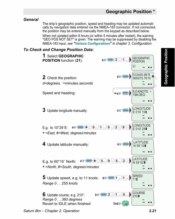
GeneralThe ship’s geographic position, speed and heading may be updated automati-cally by navigation data entered via the NMEA-183 connector. If not connected,the position may be entered manually from the keypad as described below.When not updated within 8 hours (or within 5 minutes after restart), the warning"GEO POS NOT SET" is given. The warning may be suppressed by disabling theNMEA-183 input, see "Various Configurations" in chapter 3. Configuration.
To Check and Change Position Data:
1 Select GEOGRAPHICPOSITION function (21):
2 Check the position:
d=degrees, ´=minutes.seconds
Speed and heading:
3 Update longitude manually:
E.g. to 10°29´E:
* =East, #=West, degrees’minutes
4 Update latitude manually:
E.g. to 60°15´ North:
* =North, #=South, degrees’minutes
5 Update speed, e.g. to 11 knots:
Range 0 . . 255 knots
6 Update course, e.g. 210°:Range 0 . . 360 degreesRevert to IDLE when finished:
FUNC
ON
DATA
ØÅ.
1 ABC 2 DEFPLAY
MORE/HELP
1 ABC
DATA
ØÅ. 9 LIGHT
YZÆ
2 DEFPLAY
1 ABC2 DEFPLAY
0 ÄÖÜ 0 ÄÖÜ
9 LIGHT
YZÆ 5MNO5MNO
1 ABC
1 ABC2 DEFPLAY 0 ÄÖÜ
GEOGRAPHICPOSITION21
ON
012d20.99´E060d15.76´N
ON
LONGITUDEE 010´15
ENTER
ENTER
ESC3x
ENTER
ENTER
ON
6.0 KNOTS198 DEG
ON
LATITUDEN 59´10
ON
LATITUDEN 59´52
ON
SPEED11
ON
LONGITUDEE 010´29
ENTER
ENTER
ON
COURSE210
ENTER
Geo
grap
hic
Pos
ition

Saturn Bm – Chapter 2. Operation2.22
Satellite Search *
Automatic Satellite Searching
The Saturn Bm offers two types of automatically started searches:
Initial Search performed when:• turning on power• restarting the equipment, or• Ocean Region changed by user.
Auto Search performed when:
• synchronization with the satellite has been missing for more than apreset timeout. The factory default time is 10 minutes.For presetting of the timeout period (0 . . 1440 minutes), see"Antenna Configuration" in chapter 3. Configuration.
Search Patterns
Azimuth Search
A 360° rotation of the antenna in azimuth at a fixed elevation angle.
Hemispheric Search
A hemispheric search is made out of azimuthsweeps at elevation angles 10°, 20°, 30°, 40°,50°, 60° and 70°.
The antenna searches on theactive channel frequency (NCSC).
For more information, see"Antenna Pointing" and"Satellite Searching" inchapter 4. System.
When finding the satellitesignal, it completes thehemispheric search andmoves to the position wherethe strongest signal was de-tected.
The antenna then tracks thesatellite automatically.
If no signal is detected, no further automatic action occurs until anAuto Search is activated due to the preset missing synchronizationtimeout, see above.
Sat
ellit
e S
earc
h
HEMISPHERICSE
AR
CH
70°
50°
10°
30°
ELEVATIONA
NG
LES20°
40°
60°80°
360° AZIMUTH SEARCH

Saturn Bm – Chapter 2. Operation 2.23
Satellite Search * Cont’d
Fast TrackingAt the end of a search, Saturn Bm performs a fine-tuning of theantenna position around the strongest detected signal.Fast Tracking increases the accuracy of the antenna pointing towardsthe satellite.
Direct-to-Satellite Search
The direct-to-satellite mode provides the quickest search (levels 6 or7, see below). Saturn Bm estimates the azimuth and elevation anglesof the antenna based on the following inputs:• The geographic position of the vessel supplied by GPS via the
NMEA-183 input.• The heading of the vessel as updated through the gyro interface.• Valid Bulletin Board.
Search LevelsThe search level used during an Initial Search or an Auto Search isselectable, see "Antenna Configuration" in chapter 3. Configura-tion.
The search level options are:
0: NO_SEARCH No search is performed. (Manually InitiatedSearch is possible, see next page.)
1: AZIMUTH_ONLY Search on the active NCSC frequency in thecurrent Ocean Region. One azimuth search atlast known elevation for the region.AZIMUTH_ONLY is the default selection forInitial Search.
2: ACTIVE_FREQ Search on the active NCSC frequency in thecurrent Ocean Region. One hemisphericsearch.
3: REGION_FREQS Search on all NCSC frequencies in the currentOcean Region. Up to 4 hemispheric searches,starting with the active NCSC frequency in thecurrent Ocean Region.
4: ALL_REGIONS Search on the active NCSC frequency in allOcean Regions. Up to 8 hemispheric searches,starting with the active NCSC frequency in thecurrent Ocean Region.
Sate
llite
Sea
rch
Con
t’d
Saturn Bm – Chapter 2. Operation2.24
Satellite Search * Cont’dSa
telli
te S
earc
h C
ont’d
5: FULL_SEARCH Search on all NCSC frequencies in all OceanRegions. Up to 32 hemispheric searches, start-ing with the active NCSC frequency in thecurrent Ocean Region. FULL_SEARCH is thedefault selection for Auto Search.
6: DIRECT_SAT Points the antenna directly at the satellite for thecurrent Ocean Region.
7: DIRECT_BEST Finds the best Ocean Region by searching allsatellites above the horizon.

Saturn Bm – Chapter 2. Operation 2.25
Satellite Search * Cont’d
FUNC 6 PQR2 DEFPLAY
ON
SEARCH FORSATELLITE26
ON
PRESS ENTERTO SEARCH
ON
REQUESTING
ON
COMANDACCEPTED
ENTER
ENTER
ENTER
ESC2x
ON
SEARCHINGSATELLITE
Manually Initiated Search
The Manually Initiated Search is recommended when entering anOcean Region for the first time.
To start a search:
1 Select SEARCH FORSATELLITE function (26):
2 Activate the search function:
3 Activate the search function:
4 Start the search:
The Manually Initiated Searchpattern is fixed and equals searchlevel 3: REGION _FREQS describedon the previous page.
Note! The search is independent of theoptions selected for the Initial Search andAuto Search.
If no satellite is found (search was performed onall NCSC channel frequencies in the current OceanRegion), change Ocean Region or start a new manual search.
(Changing Ocean Region starts an Initial Search, as described previ-ously, see "Automatic Satellite Search").
Sate
llite
Sea
rch
Con
t’d

Saturn Bm – Chapter 2. Operation2.26
Reading Compass Data
1 SelectREAD/SET function (29):
2 Check setting:
Entering Gyro Heading (if installed)
1 Enter current gyro heading:0 . . 360 degrees
2 Verify the setting:
Heading Input *
ON
READ/SETCOMPASS29
ON
HEADING:3 DEG
ENTER
FUNC
ON
HEADING:275 DEG
ENTER
ON
HEADING:3
ENTER
2 DEFPLAY 9 LIGHT
YZÆ
3 GHIHea
din
g In
pu
t

Saturn Bm – Chapter 2. Operation 2.27
Operational AreaThe antenna can rotate a "distance" of maximum 530°. See below.The antenna will normally stay inside the 60° - 470° operational area.
Rewind AreaWhen in IDLE mode moving into one of the 5° - 60° or 470° - 525°Rewind Areas (shaded), the antenna automatically rewinds 360° intothe Operational Area, resuming its steady pointing at the satellite.When a call is in progress and the ship turns so that the antennaenters the Rewind Area, no rewind occurs. When the call is finished,a 360° rewind will take place automatically.
Azimuth Limit AreaIf the antenna moves into the 0° - 5° or 525° - 530° Azimuth LimitAreas, rewind will start automatically despite traffic in progress and acall will be cleared.
Antenna Azimuth Limit
Ant
enna
Azi
mut
h Li
mit
1
2
0°
530°
~5°
~60°
~470°
~525
°
Operational Area
Rewind AreasThe antenna will rewind 360∞if no traffic (from e.g. 1 to 2 ; rewind time approx. 17 sec.)
Azimuth Limit AreasRewind despite traffic inprogress
Antenna searchin degrees
N
Azimuthangle read inthe display:69°
SatelliteShip’sheading:322°(Compass/gyro)

Saturn Bm – Chapter 2. Operation2.28
Relative Pointing
Suitable for manual search of the satellite based on Signal/Noise(S/N) ratio. The stronger the signal the higher S/N value.The antenna is directed manually using the arrow keys.The azimuth movement increases in speed as you hold down the key.
Procedure:
1 Select ANT.RELPOINTING function (28):
2 Check current elevation andazimuth angles:
3 Press and hold the up-key tomove the antenna clockwise (CW):
Press and hold the down-key to movethe antenna counterclockwise (CCW):
The antenna movement acceleratesas you keep holding the key.
4 Use SHIFT to toggle from azimuthto elevation mode (and back):
5 Press and hold the down-key totilt the antenna down:
Press and hold the up-key to movethe antenna up:
The antenna movement acceleratesas you keep holding the key.
6 Enter new position:
and revert:
Manual Antenna Pointing *
ON
ANT. RELPOINTING28
ENTER
FUNC
ENTER
2 DEFPLAY
LIST
LIST
8 VWXTAX
ON
EL: 77/AZ:250S/N 476
LIST
LIST
SHIFT
ON
EL: 77/AZ:276S/N 781
CW
ON
EL: 77/AZ:150S/N 0
CCW
ON
EL: 56/AZ:250S/N 80
DWN
ON
EL: 82/AZ:250S/N 189
UP
ESC3x
Man
ual A
nten
na P
oint
ing

Saturn Bm – Chapter 2. Operation 2.29
Absolute Pointing
The antenna can be directed towards the satellite by entering therequired azimuth and elevation angle data.
Procedure:
1 Select ANT.ABSPOINTING function (27):
2 Check current elevation andazimuth angles:
(the higher signal/noise valuethe better communication)
3 Key in required azimuthangle, e.g. 183°:
0 . . 360 degrees
4 Key in required elevationangle, e.g. 24°:
0 . . 90 degrees
5 Enter the antenna pointing data:
and revert to IDLE:
Manual Antenna Pointing * Cont’d
Man
ual A
nten
na P
oint
ing
ENTER
ENTER
ENTER
Signal/noise ratio
ON
ANT. ABSPOINTING27
ENTER
FUNC 2 DEFPLAY
8 VWXTAX
ON
EL: 77/AZ:250S/N 865
3 GHI
7 STU
4 JKL
1 ABC
2 DEFPLAY
ON
AZIMUTH183
ON
ELEVATION24
ON
COMMANDACCEPTED
ESC3x

Saturn Bm – Chapter 2. Operation2.30
Mes
sag
e In
dic
ato
rMessage Indicator
The Message Indicator is activated on reception of telex, telefax anddata calls. See description below.
DATA MESSAGE
TELEX MESSAGE
FAX MESSAGE
RESET
TELEX MESSAGEINDICATORLights when receivinga telex message(provided the optionalSaturn B Telexfunction is installed).
MESSAGE BUZZERSounds when receivingeither type message.Continues until reset.
RESET BUTTON.Resets buzzer andall indicators.
FAX MESSAGE INDICATORLights when receiving a telefaxmessage.
DATA MESSAGE INDICATORLights when receiving a data message(provided the optional AsynchronousData function and/or High Speed Datafunction are installed.)
For setting of response on the Message Indicator, see "VariousConfigurations" in chapter 3. Configuration.

Saturn Bm – Chapter 2. Operation 2.31
Distress Alarm
The Distress Alarm provides activation and indication of an alerttransmission and reception.
DISTRESSSaturn B
ALARMACKNOWLEDGE
ACKNOWLEDGEBUTTON.When pressed,cancels sound inthe Alarm Buzzer.
RED ALARM INDICATORand ALARM BUZZER.Flashing light and buzzer onall Distress Alarms indicatedistress alert from shore.
When answering the call, thered indicator lights steadilyand the buzzer stops. Theindicator goes off whenterminating the call.
Pressing the AcknowledgePush Button where thetelephone rings, stopsbuzzers on all DistressAlarms. Pressing the buttonat other sites only stops thebuzzer locally.
For incoming telex distressalert, see "Saturn B Telex,Operator’s Manual".
DISTRESS BUTTON.Accessible when liftingthe flap.Must be pressed andheld down for at least6 seconds to activatean alarm.
(Allows checking thealert function when setin test mode.
The Distress Alarmautomatically revertsto normal mode after30 seconds.See "Distress Test" inchapter 3.Configuration.)
RED INDICATOR.Flashes whenactivating adistress alert;slowly for 6seconds – thenquickly.
GREEN INDICATOR.Lights when the Alarmis set in test mode.
See "Distress Test"in chapter 3.Configuration.
All indicators will light ifthe Distress Alarm hasnot been configuredcorrectly.
See "Configuring Ports"in chapter 3.Configuration.)
Dis
tres
s A
larm


Saturn Bm – Operator’s Manual
ContentsContents
CO
NF
IGU
RA
TIO
N
Setting Display Contrast *........................................................... 3.1Setting Ringing Volume *............................................................ 3.2Setting Date and Time * ............................................................. 3.3Area Group Calls *...................................................................... 3.4LES Capabilities * ....................................................................... 3.5Selecting Stand-alone LES * ...................................................... 3.6Selecting Default Distress LES * ................................................ 3.7Distress Test * ............................................................................ 3.8Compass Type * ......................................................................... 3.9Antenna Configuration * ........................................................... 3.10Configuring Ports * ................................................................... 3.11Incoming Call Route * ............................................................... 3.15Various Configurations * ........................................................... 3.21Printout of Lists and Settings * ................................................. 3.22
* Functions marked with a star are only accessible whenSaturn Bm is set in OPERATOR LEVEL.See "Setting User Level" in chapter 2. Operation.
Chapter 3. Configuration
Nera SatCom AS reserves the right to change the designand specifications of the equipment without notice.


Saturn Bm – Chapter 3. Configuration 3.1
General
The contrast in the LCD display may be adjusted using functionno. 51.
Procedure
1 Select CONTRASTADJUST function (51):
2 Press ENTER todisplay the present contrast level:
3 Reduce the contrast:
or
increase the contrast:
4 Observe change in display contrastand press ENTER when suitable:
Revert when finished:
Setti
ng D
ispl
ay C
ontra
st
1 ABC5MNO
LIST
LIST
ESC
FUNC
ON
CONTRASTADJUST51
ON
CONTRAST:
ON
CONTRAST:
ON
CONTRAST:
2x
ENTER
ENTER
Setting Display Contrast *
Chapter 3. Configuration

Saturn Bm – Chapter 3. Configuration3.2
General
The level of the ringing signal in the Display Handset may be adjustedusing function no. 52:
Procedure
1 Select RINGVOLUME ADJUST function (52):
2 Press ENTER todisplay the current sound level:
3 Reduce the volume:
or
increase the volume:
4 Listen to change in ringing volumeand press ENTER when suitable:
Revert when finished:
5MNO
LIST
LIST
ESC
2 DEFPLAY
FUNC
ON
RING VOLUMEADJUST52
ON
RING VOLUME:
ON
RING VOLUME:
ON
RING VOLUME:
2x
ENTER
ENTER
Setti
ng R
ingi
ng V
olum
eSetting Ringing Volume *

Saturn Bm – Chapter 3. Configuration 3.3
Time Reference
The date and time is set to UTC (GMT) at the factory. It is recom-mended to leave this setting if correct.
Warning!The system is automatically restarted at SET TIME.All calls will be disconnected.
Example
1 Select DATEAND TIME function (53):
2 Pressing ENTER displaysthe current date & time setting:
3 Key in new date & time settings:
Year (1901 . . 2099):
Month (= 1 . .12):
Day (= 1 . . 31):
Day of week(= 1 . . 7, 1= Sunday):
Hour (= 0 . . 23):
Minute (= 0 . . 59):
Second (= 0 . . 59):
4 Enter the chosen settings:
The new date & time settings appear:
Set
ting
Dat
e an
d Ti
me
ON
DATEAND TIME53
ON
1997.07.1810:47:08SAT
ON
EDIT MODEENTER
ENTER
ENTER
ENTER
ENTER
ENTER
ENTER
ENTER
3 GHI5MNOFUNC
9 LIGHT
YZÆ 7 STU
1 ABC
ENTER
ON
YEAR1997TUE
9 LIGHT
YZÆ
6 PQR
1 ABC
2 DEFPLAY ON
MONTH10TUE
ON
DAY21TUE
ON
DAY OF WEEK2TUE
ON
HOUR6TUE
ON
MINUTE9
TUE
ON
SECOND38TUE
ON
SET TIME?
ON
1997.10.2106:09:38TUE
1 ABC 0 ÄÖÜ
2 DEFPLAY
9 LIGHT
YZÆ
3 GHI 8 VWXTAX
Setting Date and Time *

Saturn Bm – Chapter 3. Configuration3.4
Area Group Calls *A
rea
Gro
up
Cal
ls
GeneralReception of information/messages may be specified for the followingsystems:
• Navigation Area: NAVAREA function no. 22
• IMO Search and Rescue: IMO SAR function no. 23
• WMO Area: WMO AREA function no. 24
• ICAO Area: ICAO AREA function no. 25
IMO SAR, WMO AREA and ICAO AREA are set in the same way asdescribed in the example below for the NAVAREA function.
Note! Up to 3 areas may be preset for each system, see NAVAREA mapin appendix A.
Navarea Settings:
1 SelectNAVAREA function (22):
2 Check settings:(NAVAREAS 1, 2 and 3 setto 3, 7 and 12 respectively.)
3 E.g., change setting of NAVAREAno.1 automatically according topresent geographic position:Automatic selection: #Area : 0 . . 253All areas : *Change NAVAREA no.2 to 6:
Change NAVAREA no.3 to 9:
4 Verify changes:
and revert to IDLE:
FUNC
ON
2 DEFPLAY2 DEF
PLAY
6 PQR
9 LIGHT
YZÆ
SPC
NAV AREA
22
ON
NAVA AREA: 1AREA: 3
NAVA AREA: 2AREA: 7
ONNAVA AREA: 3AREA: 12
ON
NAVA AREA: 1III
NAVA AREA: 2AREA: 6
ONNAVA AREA: 3AREA: 9
ON
AREA#
ON
AREA6
ON
AREA9
ESC
ENTER
LIST
LIST
ENTER
LIST
LIST
ENTER
ENTER
ESC3x
ENTER ENTER
ENTER ENTER
ESC
ESC

Saturn Bm – Chapter 3. Configuration 3.5
GeneralInformation about the capability of all LESs in all Ocean Regions is auto-matically stored in Saturn B. The information can only be read when syn-chronized with the NCS. The abbreviations signify the following capabilities:
VFD: Voice, fax and/or dataDI: DistressDT: Distress testLD: Low speed dataBU_LES: Backup LESALONE: Stand-alone LES
Example:
1 Select LES CAPABILITIESfunction (60):
2 ENTER list of Ocean Regions:
3 Scroll to wanted Ocean Region:
4 Display LES CODE and ID, e.g. Eik, Norway:For LES Codes, see"List of Land Earth Stations"in appendix A.
5 Check capabilities of selected LES:
6 Scroll down to next LES, e.g.Burum, Netherland, LES Code 012:
7 Check capabilities:
Scroll down to next LES,or revert to IDLE:
FUNC
ENTER
0 ÄÖÜ
ON
ON
ON
MORE/HELP
6 PQR
ENTER
MORE/HELP
LESCAPABILITIES60
VFD, DI, DT
3
Ocean Region thatthe LES operates in.
LES code
Ocean Region ref. no.
LES ID, used byMES/LES communication.
Example: EIK
ENT = SELECTAOR-W 0
ENT = SELECTIOR 3
ON
IOR004 / 9 3
ESC4x ON
VFD, DI, DT
3
IOR012 / 20 3
LIST
LIST
LIST
LIST
ON
ON
LE
S C
apab
iliti
es
LES Capabilities *
Saturn Bm – Chapter 3. Configuration3.6
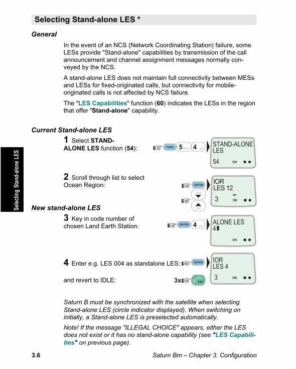
General
In the event of an NCS (Network Coordinating Station) failure, someLESs provide "Stand-alone" capabilities by transmission of the callannouncement and channel assignment messages normally con-veyed by the NCS.
A stand-alone LES does not maintain full connectivity between MESsand LESs for fixed-originated calls, but connectivity for mobile-originated calls is not affected by NCS failure.
The "LES Capabilities" function (60) indicates the LESs in the regionthat offer "Stand-alone" capability.
Current Stand-alone LES
1 Select STAND-ALONE LES function (54):
2 Scroll through list to selectOcean Region:
New stand-alone LES
3 Key in code number ofchosen Land Earth Station:
4 Enter e.g. LES 004 as standalone LES:
and revert to IDLE:
Saturn B must be synchronized with the satellite when selectingStand-alone LES (circle indicator displayed). When switching oninitially, a Stand-alone LES is preselected automatically.
Note! If the message "ILLEGAL CHOICE" appears, either the LESdoes not exist or it has no stand-alone capability (see "LES Capabili-ties" on previous page).
5MNO
4 JKL
4 JKLFUNC
ON
STAND-ALONELES
54
ON
ALONE LES4
ON
IORLES 4
3
LIST
LIST
ON
IORLES 12
3
ESC3x
ENTER
ENTER
ENTER
Sele
ctin
g St
and-
alon
e LE
SSelecting Stand-alone LES *
Saturn Bm – Chapter 3. Configuration 3.7
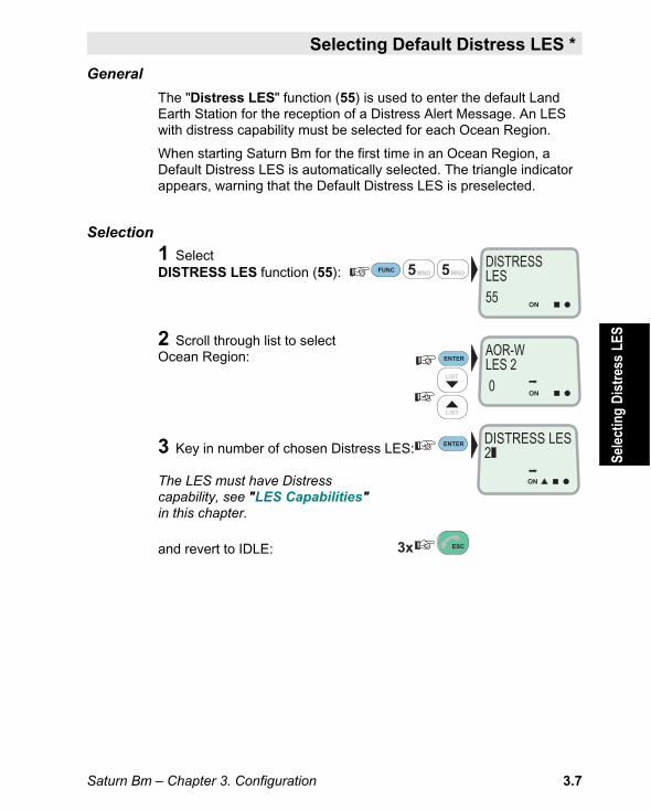
General
The "Distress LES" function (55) is used to enter the default LandEarth Station for the reception of a Distress Alert Message. An LESwith distress capability must be selected for each Ocean Region.
When starting Saturn Bm for the first time in an Ocean Region, aDefault Distress LES is automatically selected. The triangle indicatorappears, warning that the Default Distress LES is preselected.
Selection
1 SelectDISTRESS LES function (55):
2 Scroll through list to selectOcean Region:
3 Key in number of chosen Distress LES:
The LES must have Distresscapability, see "LES Capabilities"in this chapter.
and revert to IDLE:
Selecting Default Distress LES *
Sele
ctin
g D
istr
ess
LES
ON
DISTRESS LES2
LIST
LIST
ESC
ON
DISTRESSLES55
ENTER
FUNC
ON
AOR-WLES 2 0
5MNO5MNO
ENTER
3x

Saturn Bm – Chapter 3. Configuration3.8
General
The "Distress Test" function (56) permits a "distress alert" to be sentto the LES without actually initiating a distress activity.
A Default Distress LES must be entered prior to performing the test,see "Selecting Default Distress LES".
When activating the function the Distress Alarm is set in DISTRESSTEST mode for a period of 30 seconds. The green indicator on theDistress Alarm lights up indicating that a DISTRESS TEST will beinitiated when pressing the DISTRESS BUTTON.
To Set the Distress Alarm in DISTRESS TEST Mode:
1 SelectDISTRESS TEST function (56):
2 The default setting is REAL DISTRESS:
3 Press ENTER to set the Distress AlarmUnit in DISTRESS TEST MODE:
Green indicator is lit on theDistress Alarm.
4 Revert to IDLE mode:
NB! The DistressTest function automaticallyreverts to REAL DISTRESS mode if notpressing the DISTRESS BUTTON on theDistress Alarm within the 30 seconds.
Distress Test *
ON
TESTDISTRESS
ON
DISTRESSTEST56
ENTER
FUNC
ON
REALDISTRESS
5MNO
ENTER
6 PQR
ESC3xDIAL 00+INTLTEL.NO.+
ON
Dis
tres
s T
est
Saturn Bm – Chapter 3. Configuration 3.9
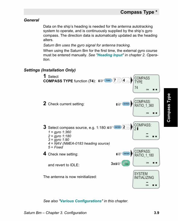
Compass Type *
General
Data on the ship’s heading is needed for the antenna autotrackingsystem to operate, and is continuously supplied by the ship’s gyrocompass. The direction data is automatically updated as the headingalters.
Saturn Bm uses the gyro signal for antenna tracking.
When using the Saturn Bm for the first time, the external gyro coursemust be entered manually. See "Heading Input" in chapter 2. Opera-tion.
Settings (Installation Only)
1 SelectCOMPASS TYPE function (74):
2 Check current setting:
3 Select compass source, e.g. 1:180:1 = gyro 1:3602 = gyro 1:1803 = gyro 1:904 = NAV (NMEA-0183 heading source)5 = Fixed
4 Check new setting:
and revert to IDLE:
The antenna is now reinitialized:
See also "Various Configurations" in this chapter.
Co
mp
ass
Typ
e
ON
COMPASS:2
ON
SYSTEMINITIALIZING
ON
COMPASSTYPE74
ENTER
FUNC 7 STU 4 JKL
2 DEFPLAY
ESC3x
ON
COMPASS:RATIO_1_360
ON
COMPASS:RATIO_1_180
ENTER
ENTER

Saturn Bm – Chapter 3. Configuration3.10
Presettable Operating Parameters:• Automatic satellite tracking on/off.• Disabling/enabling of the antenna High Power Amplifier (HPA).• Timeout limit for Auto Search initiation after missing sync.• Search level for Initial Search.• Search level for Auto Search.
For more information, see "Antenna Pointing" and "SatelliteSearching" in chapter 4. System.
Procedure (w/examples):1 SelectANTENNA CONFIG function (73):
2 Check the current setup:
3 Set the auto tracking option:0 = OFF, 1 = ON
4 Check the status of the HPA transmitter:0 = ENABLE, 1 = DISABLE (for servicepurposes only).
5 Set time to elapse before initiation of an Auto Search after loss of sync:Valid value in minutes: 0 . . 1440.
6 Set the level for the Initial Search:Valid value: 1 . . 7
7 Set the level for the Auto Search:Valid value: 1 . . 7
See "Satellite Search" in chapter 2. Operation.
Antenna Configuration *
FUNC
ON
1 ABC
MORE/HELP
5MNO
1 ABC
0 ÄÖÜ
3 GHI7 STU
3 GHI
ANTENNACONFIG.73
Search level (5)AUTO_SWEEP
ON
ON/ENABLED 30
ON
TRACKING1
ENTER
ENTER
ENTER
ENTER
ON
AZIMUTH_ONLYFULL_SEARCH
ON
TIMEOUT_TIME30
ON
INIT_SWEEP1
ON
AUTO_SWEEP5
ON
HPA_DISABLE0
ENTER
ENTER
Tracking status
Timeout
HPAstatus
Search level (1)INIT_SWEEP
Ant
enna
Con
figur
atio
n
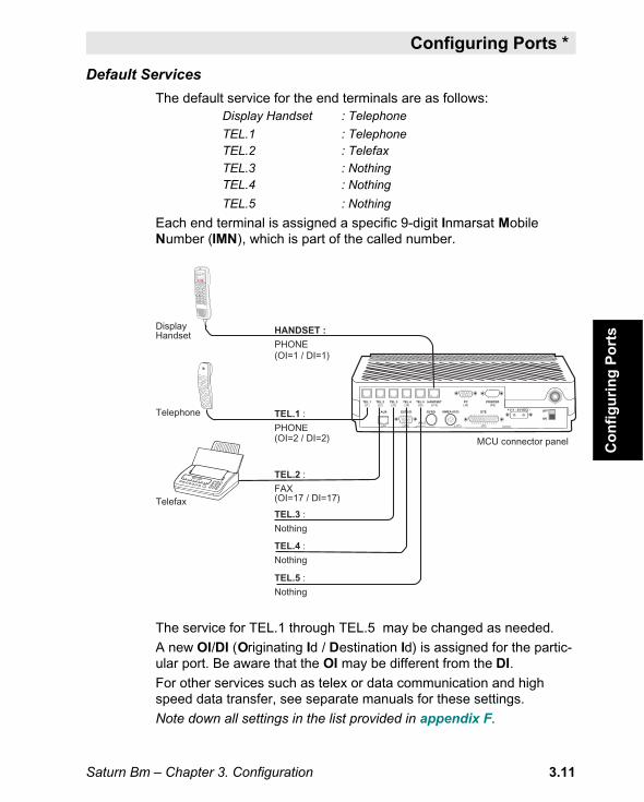
Saturn Bm – Chapter 3. Configuration 3.11
Default Services
The default service for the end terminals are as follows:Display Handset : Telephone
TEL.1 : TelephoneTEL.2 : Telefax
TEL.3 : NothingTEL.4 : Nothing
TEL.5 : Nothing
Each end terminal is assigned a specific 9-digit Inmarsat MobileNumber (IMN), which is part of the called number.
The service for TEL.1 through TEL.5 may be changed as needed.
A new OI/DI (Originating Id / Destination Id) is assigned for the partic-ular port. Be aware that the OI may be different from the DI.
For other services such as telex or data communication and highspeed data transfer, see separate manuals for these settings.
Note down all settings in the list provided in appendix F.
DisplayHandset
Telephone
Telefax
TEL.1 :
PHONE
TEL.2 :
FAX
HANDSET :
PHONE
TEL.3 :
Nothing
TEL.4 :
Nothing
TEL.5 :
Nothing
MCU connector panel
(OI=1 / DI=1)
(OI=2 / DI=2)
(OI=17 / DI=17)
FUNC ALPHA ENTER
SHIFT MORE/HELP
LESPTT
ESC
7 STU
DATA
ØÅ.
4 JKL
1 ABC
LIST
LIST
3 GHI
6 PQR
9 LIGHT
YZÆ
SPC
ON/OFF
DEL
2 DEF
PLAY
5 MNO
8 VWX
TAX
0 ÄÖÜ
ON
SHIFT BATALPHA
DIAL 00+INTLTEL.NO.+
5 4 3 2 1
9 8 7 6 25 24 23 22 21 20 19 18 17 16 15 14
13 12 11 10 9 8 7 6 5 4 3 2 1
1 2 3 4 5
6 7 8 9
(J1) (J2) (J3) (J4) (J5) (J13)
(J10)(J6)(P12)
(J7)(J11)
(J8) (P9)
5 4 3 2 1
9 8 7 6
ON
+ [11 - 34 VDC] - OFF
HANDSET
EXT I/O GYRO NMEA-0183 DTE
TEL.1 TEL.2 TEL.3 TEL.4 TEL.5
AUX
PC PRINTER
Co
nfi
gu
rin
g P
ort
s
Configuring Ports *

Saturn Bm – Chapter 3. Configuration3.12
Hexadecimal DecimalNumber Number
0 . . . . 9 0 . . . . 9
A . . . . F 10 . . . . 15
10 . . . . 19 16 . . . . 25
1A . . . . 1F 26 . . . . 31
Selecting End Terminal Service
1 Select CONFIGUREPORTS function (70):("Operator level function")
2 ENTER the list of connectors, and ifrequired scroll down to the one to bereprogrammed:
Pressing MORE/HELP displays thecurrent Originating Id for each endterminal connector:HANDSET: OI = 1TEL.1: OI = 2TEL.2: OI = 17TEL.3: NothingTEL.4: NothingTEL.5: Nothing
3 To select telephone service for the TEL.3connector e.g., key in end terminal type:1 = telephone (TPH), 2 = telefax (FAX)
4 Key in the Originating Id providedby Inmarsat e.g. 3:
Valid value is 0 . . 99
Note!The Originating Ids (OI) and Destination Ids(DI) provided by Inmarsat are hexadecimalnumbers.OI no.11, e.g., equals the decimalno. 17 in Saturn Bm.The table shows the correspondence:
Programming Distress Alarm
5 Select Distress Alarm address:
Valid value: 0 . . 7 = the addressprogrammed in the Distress Alarm installed closeto the telephone (or telex). See Installation Manual.
Keying in 7 disables the Distress Alarm.
Conf
igur
ing
Ports
Con
t’dConfiguring Ports * Cont’d
1 ABC
FUNC
LIST
LIST
0 ÄÖÜ
ON
7 STU
3 GHI
7 STU
CONFIGUREPORTS70
ON
HANDSETPHONE
ON
TEL. 1PHONE
ON
TEL. 3NOTHING
ON
ORGTERMID3
ON
TERM TYPE1
ON
DISTRESS ID7
ENTER
ENTER
ENTER
ENTER

Saturn Bm – Chapter 3. Configuration 3.13
Configuring Ports * Cont’d
Deleting End Terminal Service
Be aware that all incoming call routes established to a port must bedeleted (function 71) before configuration of a port is permitted.
Procedure:
1 Select CONFIGUREPORTS function (70):( *operator level function)
2 ENTER the list of connectors, and scroll down to wanted port, e.g. TEL.2:
3 To check assigned Originating Id:
4 Press and hold the DEL key:andpress the Y-key to delete existing setup:
If DIs have been routed to the port:remove route (and corresponding DI), see"Incoming Call Route: Deleting Call Route".
When the configuration has been deleted:
Revert to IDLE:
FUNC
LIST
0 ÄÖÜ
ON
7 STU
DEL
MORE/HELP
9 LIGHT
YZÆ
MORE/HELP
MORE/HELP
ESC
CONFIGUREPORTS70
3x
ON
HANDSETPHONE
ON
TEL. 2FAX
ON
OI = 17
ON
PORT EXISTIN ROUTE
ON
DELETE ?Y = YES
ENTER
Originating Id
ON
DELETE ROUTEFIRST
ON
TEL.2NOTHING
ON
OI = 0
Conf
igur
ing
Ports
Con
t’d

Saturn Bm – Chapter 3. Configuration3.14
Configuring Ports * Cont’d
Setup (Example with all Ports Configured)Saturn B is delivered with the Handset, TEL.1, TEL.2 and PC connectorsconfigured with default end terminal Originating & Destination Ids. The TEL.3through TEL.5 connectors must be configured at the installation of the equip-ment. Connectors TEL.1 through 5 may be reconfigured later as required.
DisplayHandset
Telephone
Calls (examples):End terminals:
(Originating Id)
(Destination Id)
Distress Alarm(Address = 0)
(OI =1)(DI = 1) + 873 682420510
(OI = 2)(DI = 2) + 873 682420511
(OI = 17)(DI = 17) + 873 682420520
(OI = 3)(DI = 3) + 873 682420512
(OI = 4)(DI = 4) + 873 682420513
(OI = 18)(DI = 18) + 873 682420521
(IMN)
(Originating Id)(Distress Id)
Configuring ports:
(Oc.Reg.)
7
4
1 3
6
9
DEL
2
5
8
0
DIAL 00+INTLTEL. NO.+
ONSHIFT
HANDSET
EXT I/O
(ORGTERMID=1)(DISTRESS = 0)
TEL.1(ORGTERMID=2)(DISTRESS = 7)
Distress Alarm(Address = 3)
EXT I/O
TEL.3(ORGTERMID=3)(DISTRESS = 3)
TEL.4(ORGTERMID=4)(DISTRESS = 7)
TEL.5(ORGTERMID=18)(DISTRESS = 7)
Telephone
Telephone
Telefax
Telefax
TEL.2
(ORGTERMID=17)
DISTRESSSaturn M
DISTRESSSaturn M
Conf
igur
ing
Ports
Con
t’d

Saturn Bm – Chapter 3. Configuration 3.15
GeneralThe Incoming Call route function no. 71 is used to link a received callto the wanted end terminal connector(s). As a default, the HANDSET,TEL.1, and TEL.2 connectors have been set up with a standard pairof OI/DIs, see previous page. (E.g., an incoming call with an IMNcontaining DI no.17 is routed directly through to connector TEL.2).
Setting Call RouteThe connectors TEL.3 through TEL.5 have no default settings andmust be provided with the appropriate DI. Note that if changing a callroute, you may be prompted to delete the current setting first.
Example:1 Select INCOMINGCALL ROUTE function (71):
2 ENTER list of DIs:
3 Key in new DI, e.g. 3 :
4 Key in service type:1=telephone (TPH), 2=telefax (FAX)4=telex (TLX), 5=high speed data (HSD)
5 Set the routing toe.g. TEL.3 only:H : Handset connector1, 2, 3, 4, 5 : Telephone/telefax connectorsP : Not used in Saturn BSetting=1 : IMN with DI is routed to deviceSetting=* : IMN with DI is not routed to deviceNote! A call can only be routed to a connector with the same service type asthat of the call. For other services such as telex or data communication andhigh speed data transfer, see separate manuals for these settings.Note down all settings in the list provided in appendix F.
6 Check entries:
and revert to IDLE:
Inco
min
g C
all R
oute
Incoming Call Route *
ON
RING H12345PON 1
1 ABC
FUNC
ON
7 STU
3 GHI
1 ABC
DATA
ØÅ.DATA
ØÅ.DATA
ØÅ.
1 ABC
INCOMINGCALL ROUTE71
DI
Service
ON
TELEPHONY
1
ON
0
3
ON
SERVICE13
ENTER
ENTER
ON
TELEPHONY
3
ENTER
ESC3x
ENTER
ENTER
ENTER

Saturn Bm – Chapter 3. Configuration3.16
Deleting Call RouteWhen e.g. changing the service of a connector from telefax to tele-phone, the route established to the particular connector must bedeleted. (Be aware that the OI and DI numbers may be different).Example:
1 Select INCOMINGCALL ROUTE function (71):
2 ENTER list of DIs:
3 Scroll down to DI e.g. no.17:
4 Press and hold the DEL key:andpress the Y-key to delete existing setup:
and revert to IDLE:
Note! Incoming calls with DI=17 (telefax call) will now be rejected.
FUNC
ON
7 STU 1 ABC
LIST
DEL
ESC
9 LIGHT
YZÆ
INCOMINGCALL ROUTE71
3x
ON
TELEPHONY
1
ON
FACSIMILE
17
ENTER
ON
DELETE ?Y = YES
Inco
min
g Ca
ll Ro
ute
Cont
’dIncoming Call Route * Cont’d

Saturn Bm – Chapter 3. Configuration 3.17
Routing Table (Example)
The table below shows examples of routing of incoming calls (withIMNs and Destination Ids provided by Inmarsat) to the end terminals.
As indicated, some of the incoming calls have been extended to alsocall other end terminals. Note that an incoming call can be extendedto maximum three additional telephones.
A blank table is provided in appendix F, allowing the owner to fill inthe routing implemented in his particular installation. If changing therouting later, it is recommended to update the table accordingly.If a printer is connected to the MCU, a "Configuration info" printout willprovide the call route settings, see "Printout of Lists and Settings".
Note!If changing the service for an end terminal from telephone to telefaxor vice versa, all routes to the connectors involved must be deletedfirst, see “ Deleting Call Route” .
Tele
phon
e =
1, T
elef
ax =
2Te
lex
= 4,
HSD
= 5
ROUTING OF INCOMING CALLS
IMN
662420510
662420511
662420520
662420512
662420513
662420521
DI
1
2
17
3
4
18
1
1
1
1
1
1
1
1
1
1
1
Calls to Handset alsorouted to TEL.1, 3&4
Comments
No extendedrouting of calls
Calls to TEL.3 alsorouted to TEL.1
Calls to TEL.4 alsorouted to HANDSET
Telefax calls. No ext.routing allowed.
Telefax calls. No ext.routing allowed.
Connectors on MCUHDST TEL.1 TEL.2 TEL.3 TEL.4 TEL.5
The IMNs(InmarsatMobileNumber) areexamplesonly.
Des
tinat
ion
Iden
tific
atio
n di
gits
Example showing routing of DI no.1
1
1
2
1
1
2
Ser-vice
ON
RING H12345PON 11 11
Incoming Call Route * Cont’d
Inco
min
g Ca
ll Ro
ute
Cont
’d

Saturn Bm – Chapter 3. Configuration3.18
To check the settings in the Routing Table (see preceding page)
1 Select INCOMINGCALL ROUTE function (71):(* operator level function)
2 Read out Display Handsetservice and Destination Id:
and
check setting:
3 Scroll down to DI no.2:
and
check routing to TEL.1:
4 Scroll down to DI no.17:
and
check routing to TEL.2:
5 Scroll down to DI no.3:
and
check routing to TEL.2 and TEL.3:
6 Scroll down to DI no.4:
and
check routing to TEL.4:
7 Scroll down to DI no.18:
and
check routing to TEL.5:
Revert to IDLE mode:
FUNC
ON
7 STU 1 ABC
LIST
LIST
LIST
LIST
LIST
H: Handsetconnector1, 2, 3, 4, 5:TelephoneconnectorsP: Not usedon Saturn B
INCOMINGCALL ROUTE71
DI
Service
ON
TELEPHONY
1RING H12345PON 11
ON
ON
TELEPHONY
2
RING H12345PON 1
ON
ON
FACSIMILE
17
RING H12345PON 1
ON
ON
TELEPHONY
3
RING H12345PON 11
ON
ON
TELEPHONY
4
RING H12345PON 1
ON
ON
FACSIMILE
18RING H12345PON 1
ONESC3x
MORE/HELP
ENTER
MORE/HELP
MORE/HELP
MORE/HELP
MORE/HELP
MORE/HELP
Incoming Call Route * Cont’dIn
com
ing
Call
Rout
e Co
nt’d

Saturn Bm – Chapter 3. Configuration 3.19
Extended Routing of Incoming Calls
To route TEL.1 (DI=2) also to HANDSET (DI=1):
1 Select INCOMINGCALL ROUTE function (71):
2 ENTER list of DIs:
3 Check current setting:
4 Scroll down to DI no.2:
5 Accept service type (or key in):
1=telephone (TPH), 2=telefax (FAX)4=telex (TLX), 5=high speed data (HSD)
6 Enter the routing prompt:
Change settings:
and revert to IDLE:
FUNC
ON
7 STU 1 ABC
LIST
1 ABC1 ABC
H: Handsetconnector1, 2, 3, 4, 5:TelephoneconnectorsP: Not usedon Saturn B
INCOMINGCALL ROUTE71
ON
TELEPHONY
1
ESC3x
ENTER
ON
TELEPHONY
2
MORE/HELP
ENTER
RING H12345PON 11
ON
RING H12345PON 1
ON
ENTER
ENTER
ON
SERVICE1
Incoming Call Route * Cont’d
Inco
min
g Ca
ll Ro
ute
Cont
’d

Saturn Bm – Chapter 3. Configuration3.20
Changing Call Route from FAX to PHONE
To change the routing to TEL.2 from FAX to PHONE,(DI=17 to DI=3):
1 Select INCOMINGCALL ROUTE function (71):
2 ENTER list of DIs:
3 Scroll down to DI no.17:
4 Press and hold the DEL key:andpress the Y-key to delete existing setup:
5 Key the DI assigned by Inmarsat, e.g. 3:
6 Change to TELEPHONE service:
7 Change routing:
If the message "Routed to wrong type" appears,change existing configuration of TEL.2 from FAXto PHONE, see "Configuring Ports:Selecting End Terminal Service".
check entries:
and revert to IDLE:
FUNC
ON
7 STU 1 ABC
LIST
1 ABC
3 GHI
9 LIGHT
YZÆ
DEL
1 ABCDATA
ØÅ.DATA
ØÅ.
INCOMINGCALL ROUTE71
ON
TELEPHONY
1
ESC3x
ENTER
ON
FACSIMILE
17
ON
SERVICE0
ON
DELETE ?Y = YES
ON
0
3
ENTER
RING H12345PON 1
ON
ON
TELEPHONY
3
ENTER
ENTERENTER
Incoming Call Route * Cont’dIn
com
ing
Call
Rout
e Co
nt’d

Saturn Bm – Chapter 3. Configuration 3.21
GeneralThe "Various Config" function (77) is used to select the followingdefault settings:• Routing of printouts to PRINTER or DTE port.• Routing of Service Announcements from LES/NCS.• Setting of response on the remote Message Indicator.• Selection between manual update of geographic position, and
automatic update through the NMEA-0183 port.• Enabling/disabling of low power standby detection level in the 2W telephone ports.
Setting1 Select VARIOUSCONFIG function (77):
2 Check current settings:The example shows as follows:• printouts routed to PRINTER.• service announcements routed to PC.• Message Indicator responds to telefax
and telex.• manual course input, NMEA-183 off.
3 Select routing of printouts:0=no output, 2=to printer,3=to DTE port
4 Select routing ofServices Announcements, e.g. to PC:0=no output, 1=to PC port.2=to printer, 3=to DTE port.
5 Set Message Indicator response:F=telefax, T=telex, D=data(1=indication, *=no indication)(SW version no. 2.03 and above only)
6 Select position input source:0=manual input, 1=NMEA-0183 inputNote! When manual update has been selected,new geographic position must be entered manually.
7 Turn on or off standby:0=disabled (OFF), 1=enabled (ON)
and revert to IDLE:
1 ABC
FUNC
ON
7 STU
DATA
ØÅ.
1 ABC
7 STU
1 ABC
2 DEFPLAY
MORE/HELP
1 ABC
1 ABC
VARIOUSCONFIG77
ON
TO PRINTERTO PC
ON
DEF.PRINTER2
ENTER
ENTER
ESC3x
ENTER
ENTER
ON
MSGIND: 11NO NMEA
ON
FTD (MSGIND)11
ON
POS.SOURCE1
ON
COMBO LOWPWR1
ON
SERV.ANN PRN1
ENTER
ENTER
ENTER
Vario
us C
onfig
urat
ions
Various Configurations *

Saturn Bm – Chapter 3. Configuration3.22
General
With a serial printer connected to the PRINTER port on the Maincontrol Unit, it is possible to print out lists and settings from theSaturn B terminal.
The printer must be set as follows:
• 4800 bps
• No parity
• 8 data bits
• 1 stop bit
See also "Various Configurations" in this chapter.
Printing a full Set of Lists:
1 Select the main menu ALARMSAND MESSAGES (3-):
2 Press SHIFT + PLAYto start printout:
Printing Specific Lists:
Press SHIFT + PLAY when in functions as listed:
Function Heading
(10) SHORT NUMBER LIST "Short number list"
(30) ACTIVE ALARMS "Active alarms"
(31) INFO LOG "Event log"
(32) CLEAR CAUSE LOG "Clear cause log"(33) TERMINAL STATUS "Status"
(4-) SYSTEM INFORMATION "System info"
(70) CONFIGURE PORTS "Configuration info"
(89) ENHANCED SETUP "Enhanced configuration info"
FUNC
ON
SHIFT
3 GHI
2 DEFPLAY
ALARMS ANDMESSAGES3-
Pri
nto
ut
of
Lis
tsan
d S
etti
ng
sPrintout of Lists and Settings *

Saturn Bm Marine – Operator’s Manual
Contents
SY
ST
EM
Description .................................................................................. 4.1Communication........................................................................... 4.3Antenna Pointing ........................................................................ 4.8Satellite Searching.................................................................... 4.10
Chapter 4. System


Saturn Bm – Chapter 4. System 4.1
Inmarsat-B System
Inmarsat-B is a satellite communication system providing highly-reliable telephone, data and facsimile communications to and frommobile subscribers anywhere within the coverage area of the INMAR-SAT system, from 70°S to 70°N.
Des
crip
tio
nFigure 4.1 Overview of the Inmarsat-B system.
LES
NCS
MES
TELEPHONENETWORKS
NCS: Network Coordinating StationLES: Land Earth StationMES: Mobile Earth station
(Saturn B terminal)
MES
DATANETWORKS
TELEXNETWORKS
NCS Network Coordinating Station LES Land Earth Station MES MobileEarth StationChapter 4. System
Description

4.2 Saturn Bm – Chapter 4. System␣ ␣
System Satellites
The positions of the four sys-tem satellites are indicated inFigure 4.2.
The satellites are posi-tioned in a geostation-ary orbit above theequator at approxi-mately 35700 kmaltitude.
In geostationary orbit,each satellite moves atthe same rate as theearth, and so remains inthe same relative positionto the earth.
The satellites cover approximately 1/4 of the earth each, calledOcean Regions:
• Atlantic Ocean East Region
• Pacific Ocean Region
• Indian Ocean Region
• Atlantic Ocean West Region
The four Ocean Regions represent areas within which Saturn B cancommunicate via a selected satellite.
The coverage area of the satellites is shown on the map inappendix A.
Des
crip
tio
n C
on
t’d
EQUATOR
EARTH
12000 km
35700 kmPacific Ocean Region
Indian Ocean Region
54°W 64.5
°E
178°E
15.5°W
Atlantic Ocean Region (West)
Atlantic Ocean Region (East)
Figure 4.2 Satellite positions.
Description Cont’d

Saturn Bm – Chapter 4. System 4.3
Saturn Bm Communication
The Saturn Bm Marine terminal provides direct telephony, telex anddata connection to the international public networks via the INMAR-SAT satellite system.
The digital technology used in the system ensures complete privacyfor the calls.
The Saturn Bm Marine terminal consists of only two units, the AboveDeck Equipment (ADE) and the Below Deck Equipment (BDE), with asingle cable connecting them.
The installation is very simple. The complete installation can normallybe done by one engineer in less than a day.
The basic system consists of the compact Main Control Unit (MCU)w/Display Handset, the antenna radome containing stabilized anten-na, transceiver and tracking system and a Distress Alarm Unit.
All operating functions are conducted through the telephone DisplayHandset.
The Saturn Bm also offers connection of 5 telephones, telefax, Mes-sage Indicator, telex PC, and PC for data transfer via its built-inmodem (option).
Figure 4.3 Communication path.
Saturn BmMarine
Land EarthStation
LESDisplayHandset
Path established bySaturn Bm terminal
via satellite
Telephone(s)Local PABXTelefaxTelexData/modem communication (option)
Saturn B
7
4
13
6
9
DEL
2
5
8
0
DIAL 00+INTLTEL.NO.+
ONSHIFT
PublicDataNetwork
Telefax
PublicTelephoneNetwork
PC/modem
PublicTelexNetwork
Co
mm
un
icat
ion
Communication

4.4 Saturn Bm – Chapter 4. System␣ ␣
Services
• Duplex telephone calls – basic telephony services.
• Simplex telephone calls – LES-to-mobile only.• Duplex telefax – CCITT Group 3 facsimile services, 9.6 kbps.
• Simplex telefax calls – LES-to-mobile only.
• Simplex Group ID addressing – to a selected group of mobiles.
• Duplex data communication – Hayes compatible 9.6 kbps dataservice.
• Duplex telex communication.
• Simplex telex communication.
• Service Announcements.
• Duplex high speed data – 56/64 kbps.
Calls from Mobiles
To initiate a call, the user dials the international call prefix 00 prior tothe telephone number for the required destination. The LES codenumber is also included, either automatically when using the defaultLES, or manually selected from the Display Handset.
The mobile automatically includes information to identify the MES andthe particular end terminal that originates the call. Saturn B has sixvoice connections: the Display Handset and five connectors (oneinternal and four external) that are normally configured for telephoneand a telefax.
The LES uses the end terminal identifying information (OI) for billingpurposes.
The mobile transmits the dialing information on a channel speciallyassigned by the NCS, to the LES, which also has been instructed totune to the same channel.
On receiving the call, LES routes it over the public telecommunica-tions networks to the intended destination. When the called partyresponds, the call proceeds.
See simplified call initiation illustrated on the next page.
Com
mun
icat
ion
Con
t’dCommunication Cont’d

Saturn Bm – Chapter 4. System 4.5
PS
TN
00 4
7 67
24
47 0
0
Cal
ls f
rom
Mo
bile
s
Forw
ard/
retu
rn ID
1234
56/A
BC
DE
F
OI
1
Typ
e
Voi
ce
Com
mis
sion
ed
Yes
67 2
4 47
00
LES
Tra
nsla
tion
Tab
le
12
3
45
6
78
9
0#
PS
Re
ME
S T
rans
latio
n T
able
Whe
n th
e M
ES
orig
inat
es a
cal
l it s
tart
sby
sen
ding
a r
eque
st to
the
LES
.T
his
initi
al r
eque
st fo
r se
rvic
e co
ntai
nsth
e M
ES
Ret
urn
ID a
nd ty
pe o
f ser
vice
.S
atur
n B
m in
corp
orat
es a
con
figur
atio
nta
ble
for
orig
inat
ing
info
rmat
ion,
acce
ssib
le th
roug
h th
e “C
onfig
ure
Por
ts”
func
tion
(70)
. Thi
s ta
ble
cont
ains
one
entr
y fo
r ev
ery
phys
ical
con
nect
or w
ithth
e O
rigin
atin
g Id
and
type
of s
ervi
ce fo
rth
at s
peci
fic c
onne
ctor
.
LE
S
Ret
urn
ID
Typ
e
2 AB
CD
EF
Voi
ce
Acc
ess
Req
uest
Fw
d ID
Rx
ch.
Tx
ch.
1234
56
8192
1200
0
Cha
nnel
ass
ignm
ent
Sat
urn
B
7413 6 9
2 5 8 0ON
DIA
L 00
+IN
TL
TE
L.N
O.+
Co
nn
ecto
rS
ervi
ce/
Ori
gina
ting
Id
Pho
ne/O
I=1
Pho
ne/O
I=2
Fax
/OI=
17
Def
ault=
no O
I
Def
ault=
no O
I
Def
ault=
no O
I
Tel
ex/O
I=49
HA
ND
SE
T
TE
L.1
TE
L.2
TE
L.3
TE
L.4
TE
L.5
PC
LE
S=
2
Re
P
–
7
8
9
4
5
6
1
2
3
SS
0
#
R
Satu
rn B
NE
RA
Com
mun
icat
ion
Con
t’d
Communication Cont’d

4.6 Saturn Bm – Chapter 4. System␣ ␣
Com
mun
icat
ion
Con
t’dCommunication Cont’d
Calls to Mobiles
Calls are made as ordinary international (Satellite) calls where eachOcean Region has an international country code. If an area is cov-ered by more than one satellite, it is necessary that the caller knowswhich satellite (Ocean Region) the mobile is tuned to.
See simplified call illustrated initation on the next page.
The international codes to the four Ocean Regions are as follows:Atlantic Ocean East Region: 871
Pacific Ocean Region: 872
Indian Ocean Region: 873
Atlantic Ocean West Region: 874

Saturn Bm – Chapter 4. System 4.7
Re
P
–
7
8
9
4
5
6
1
2
3
S
0
#
R
DI
1 2 17
Tel
epho
neR
ing
on h
ands
et
Cal
ls t
o M
ob
iles
00 8
71 6
8123
4567
Tel
epho
neR
ing
on T
EL.
1F
acsi
mile
Rin
g on
TE
L.2
Inco
min
gca
ll ro
ute
ME
S T
rans
latio
n T
able
12
3
45
6
78
9
0#
PS
Re
TE
L.3
No
DI
TE
L.4
No
DI
TE
L.5
No
DI
Whe
n re
ques
ted
to c
all a
spe
cific
IMN
, LE
S tr
ansl
ates
the
IMN
to a
For
war
d ID
and
a D
estin
atio
n Id
(D
I).
The
req
uest
is th
en s
ent t
o th
e M
ES
whi
ch tr
ansl
ates
the
For
war
d ID
and
the
DI
to a
phy
sica
l lin
e to
cal
l.
To
"con
nect
" a
Des
tinat
ion
Id to
a p
hysi
cal l
ine,
Sat
urn
Bm
inco
rpor
ates
a tr
ansl
atio
n ta
ble
acce
ssib
leth
roug
h th
e “I
ncom
ing
call
rout
e” fu
nctio
n (7
1). T
his
tabl
eca
n co
ntai
n up
to 1
00 D
I tra
nsla
tions
, and
eac
h D
I in
use
is p
rogr
amm
ed w
ith t
ype
of c
all a
nd d
estin
atio
n.
A c
all i
s no
t allo
wed
to b
e ro
uted
to a
con
nect
or th
at is
conf
igur
ed to
ano
ther
type
than
the
DI s
peci
fies.
A te
leph
one
DI c
an o
nly
be r
oute
d to
a p
hone
type
conn
ecto
r. A
facs
imile
DI c
an o
nly
be r
oute
d to
a fa
xty
pe c
onne
ctor
.
LE
S
Fwd
ID
Typ
e
DI
2 1234
56
Voi
ce
1
Cal
l ann
ounc
emen
t
Sat
urn
B
PC
4
9
LES
Tra
nsla
tion
Tab
le
Forw
ard/
retu
rn ID
1234
56/A
BC
DE
F
1234
56/A
BC
DE
F
1234
56/A
BC
DE
F
1234
56/A
BC
DE
F
DI
01 02 17 49
Typ
e
Voi
ce
Voi
ce
Fax
Tel
ex
IMN
6812
3456
7
6812
3478
9
6812
3489
0
6812
3448
1
7413 6 9
2 5 8 0ON
DIA
L 00
+IN
TL
TE
L.N
O.+
LE
S=
2
LE
S
Ret
urn
ID
Typ
e
2 AB
CD
EF
Voi
ce
Res
pons
e
Satu
rn B
NE
RA
Com
mun
icat
ion
Con
t’d
Communication Cont’d

4.8 Saturn Bm – Chapter 4. System␣ ␣
GeneralThe antenna is highly directive and must be pointed accurately at thesatellite to achieve optimum receiving and transmitting conditions.During normal operation the antenna is kept pointed at the satellite bythe auto-tracking system of Saturn Bm.
However, before the auto-tracking can take over, the antenna mustbe brought within a certain angle of the satellite.
For manual pointing, the following data must be available:
Ship’s Plotted Position
The plotted position isneeded to decide whichsatellite can be used. SeeSatellite Coverage Map inappendix A.
Example: 106° 10' E,9° 40' N
Ship’s Heading
The ship’s heading is needed to givecorrect azimuth reading in the DisplayHandset.
106° 10' E
105° 106° 107° 108°E
11°N
10°
9°
8°
09° 40' N
NShipsheading
322°
Antenna PointingA
nten
na P
oint
ing

Saturn Bm – Chapter 4. System 4.9
Azimuth Angle
The azimuth angle is the angle be-tween north and the horizontal satel-lite direction as seen from the ship.
Example: 259° azimuth
The actual azimuth angle for thesatellites relative to the ship’sposition can be found on theAzimuth Map in appendix A.
Elevation Angle
The elevation angle is the satellite height above the horizon as seenfrom the ship.
Example: 38° elevation
The actual elevation angle for the satellites relative to the ship’sposition can be found on the Elevation Map in appendix A.
Earth surface
Satellite
Horizon
Elevation
38°
Equator
N
Azimuth259°
Satellite
Antenna Pointing Cont’d
Ante
nna
Point
ing C
ont’d

4.10 Saturn Bm – Chapter 4. System␣ ␣
Introduction
The Saturn Bm may find a satellite and obtain synchronization in oneof several ways:
• searching automatically when required.
• the user starts a search from the keypad.
• the user moves the antenna using the keypad.
Automatically Initiated Search
Two different “search types” are used:
Initial Search which starts automatically• at power on/restart, or• when changing Ocean Region
Auto Search which starts automatically• when losing synchronization for a preset time interval.
(For setting the time interval, see "Antenna Configuration" inchapter 3. Configuration.)
Search Patterns
The two search types above can be individually configured to performone of several search algorithms, called “search levels”:
Search Name Descriptionlevel
0 NO_SEARCH No search is performed.Manually Initiated Search is still possible.
1 AZIMUTH_ONLY Search on the active NCSC frequency in the currentOcean Region at last known elevation for the region.One 360 degree search in azimuth.
2 ACTIVE_FREQ Search on the active NCSC frequency in the currentOcean Region.One hemispheric search.
3 REGION_FREQS Search on all NCSCs in current Ocean Region. One ortwo hemispheric searches.
4 ALL_REGIONS Search on active NCSC in all Ocean Regions.One to max eight hemispheric searches
5 FULL_SEARCH Search for all NCSCs in all Ocean Regions.One to max thirty-two hemispheric searches.
6 DIRECT_SAT Points the antenna directly at the satellite for the currentOcean Region.
7 DIRECT_BEST Finds the best Ocean Region by searching all satellitesabove the horizon.
(See chapter 2. Operation for a description of hemispheric search).
Satellite SearchingS
atel
lite
Sea
rchi
ng

Saturn Bm – Chapter 4. System 4.11
The Saturn Bm search algorithms are designed to find a satellite assoon as possible.
The FULL_SEARCH level, covering all NCSC frequencies for each ofthe eight Ocean Regions may cause the antenna to perform up to 32hemispheric (sky) searches.
The REGION_FREQS and ALL_REGIONS search levels may alsorequire several hemispheric searches before a signal is found.
The DIRECT_SEARCH and the REGION_SEARCH search levels arerecommended used when the ship’s heading and position data areaccessible.The DIRECT_SEARCH level points the antenna directly at the satel-lite of the current Ocean Region.The REGION_SEARCH steps the antenna from satellite to satelliteand finally settles on the best one.Choosing between Initial Search and Auto Search permits a limitedsearch to be made with a high possibility of finding a satellite. Whichsearch levels to select is up to the user and should be based onunder what conditions the system is used.
The Initial Search is activated when the system is started or when theuser changes Ocean Region. Saturn Bm remembers the last usedOcean Region, last used NCSC frequency and the antenna position.
Saturn Bm in fact keeps a record of these data for all Ocean Regions.
The Auto Search is activated when synchronization with the satellitehas been lost for a preselected time interval. Loss of synchronizationmay be caused by different situations, e.g. when:• Moving out of the current Ocean Region.
• Moving into a “shadow” where the satellite signal is not seen,(caused by mast, funnel etc. on your own vessel, another vessel, abridge, buildings, geographical obstacles etc.).
• Changing to an Ocean Region not covering your position (startingwith Initial Search and then Auto Search after timeout).
• INMARSAT changes the active NCSC frequency in your OceanRegion.
Satellite Searching Cont’d
Sate
llite
Sear
ching
Con
t’d

4.12 Saturn Bm – Chapter 4. System␣ ␣
Active NCSC Frequency
The active NCSC frequency here is the frequency that Saturn Bmassumes is the active one. Saturn Bm uses the frequency that wasactive the last time the actual Ocean Region was used.
When using an Ocean Region for the first time, the active NCSCfrequency is selected as default, i.e. NCSC (0). That is why a Manu-ally Initiated Search is recommended when using an Ocean Regionfor the first time.
The Search Levels
NO_SEARCH
During Initial Search the system tunes to the last used NCSC fre-quency and positions the antenna directly to the last known position.
If NO_SEARCH is used for Auto Search the antenna maintains itsposition even after loss of synchronization.
NO_SEARCH is recommended when the antenna is located at afixed geographical position. Use the Manually Initiated Search afterinstallation (see below) to find the satellites for the Ocean Regionscovering your position. When restarting or changing Ocean Region,the antenna will be pointed to the satellite directly.
AZIMUTH_ONLY
Default search level for the Initial Search. The system tunes to thelast used NCSC frequency and adjusts the antenna to the last usedelevation angle, before performing a 360-degree azimuth search. Theantenna moves to the position with the best signal strength.
If no signal is detected, the antenna moves back to the last usedposition.
During Auto Search the system performs a 360 degree azimuthsearch.
AZIMUTH_ONLY is recommended for Initial Search when the vesselmoves in directions causing small changes in the elevation angle.
Small changes in elevation can be expected when the vessel’scourse is mainly east or west.
AZIMUTH_ONLY is not recommended for Auto Search unless thevessel always operates within the same Ocean Region.
Satellite Searching Cont’dSa
tellit
e Se
arch
ing C
ont’d

Saturn Bm – Chapter 4. System 4.13
The difference between Initial Search and Auto Search is that AutoSearch makes a 360 degree azimuth search prior to the hemisphericsearch(es):
ACTIVE_FREQ
During Initial Search the system tunes to the last used NCSC fre-quency and makes one hemispheric search. The antenna moves tothe position where the best signal was detected during the search. Ifno signal was detected, the antenna moves back to the last usedposition.
During Auto Search the system starts an AZIMUTH_ONLY search.But if no signal is found, a hemispheric search is performed.
ACTIVE_FREQ is recommended for Initial Search when the vesselmoves in directions that may cause significant changes in the eleva-tion angle.
ACTIVE_FREQ is not recommended for Auto Search unless thevessel always operates within the same Ocean Region.
REGION_FREQS
starts as an ACTIVE_FREQ search. But if no signal is found, hemi-spheric searches are tried on the other NCSC frequency assigned tothe current Ocean Region.
If a signal is found during one of the hemispheric searches, thathemispheric search is completed, and the antenna moves to theposition where the best signal was detected.
Since there are two NCSC frequencies assigned to an Ocean Region,this search level requires one or two hemispheric searches to com-plete.
REGION_FREQS can be used for Initial Search instead of ACTIVE_FREQ.
It is useful if INMARSAT changes the active NCSC frequency for yourOcean Region. (Only one of the four NCSC frequencies assigned toan Ocean Region is active at a time.)
REGION_FREQS is not recommended for Auto Search unless thevessel always operates within the same Ocean Region.
REGION_FREQS search algorithm equals the one used for theManually Initiated Search.
Satellite Searching Cont’d
Sate
llite
Sear
ching
Con
t’d

4.14 Saturn Bm – Chapter 4. System␣ ␣
ALL_REGIONS
An ALL_REGIONS search starts as an ACTIVE_FREQ search. But ifno signal is found, hemispheric searches are tried on the activeNCSC frequencies for the other Ocean Regions.
If a signal is found during one of the hemispheric searches, thathemispheric search is completed, and the antenna moves to theposition where the best signal was detected. If the signal is found inan Ocean Region other than the initial one, the system is automati-cally tuned to the new Ocean Region. Since eight Ocean Regions aredefined, this search level requires from one to eight hemisphericsearches to complete.
ALL_REGIONS is probably to extensive for an Initial Search, but isrecommended for Auto Search, specially if loss of synchronization iscaused by moving out of the current Ocean Region.
FULL_SEARCH
Default search level for Auto Search, starting as an ACTIVE_FREQsearch.
The FULL_SEARCH is performed in the same way as describedabove for the ALL_REGIONS search, but both NCSC frequencies inall Ocean Regions are searched. Since eight Ocean Regions aredefined with four NCSC frequencies each, this search level requiresfrom one to thirty-two hemispheric searches to complete.
DIRECT_SAT
By using the ship’s current heading and position (latitude/longitude)the exact azimuth/elevation may be calculated, allowing theDIRECT_SAT search to point the antenna directly at any satellite ofthe current Ocean Region.
An alarm is given if the attempted satellite is below the horizon.
DIRECT_BEST
The DIRECT_BEST search steps the antenna from satellite to satel-lite, and measures all NCSC frequencies. When all satellites abovethe horizon have been measured, the antenna is pointed at the satel-lite providing the strongest signal. The latter is then established as thenew "current Ocean Region".
Satellite Searching Cont’dSa
tellit
e Se
arch
ing C
ont’d

Saturn Bm – Chapter 4. System 4.15
Satellite Searching Cont’d
Sate
llite
Sear
ching
Con
t’d
When starting Saturn Bm in an Ocean Region for the first time, andsynchronization is not obtained after start-up, check that the OceanRegion setting is correct and start a Manually Initiated Search fromthe keypad:
Starting a Search from the Keypad
The Manually Initiated Search may be useful if an Initial Search orAuto Search fails to obtain synchronization with a satellite, or whenyou enter an Ocean Region for the first time (or when the activeNCSC frequency of your current Ocean Region has been changed byINMARSAT).
It could also be useful if you suspect that a search finds a reflectedsignal rather than the true signal. This may happen in an InitialSearch because the Initial Search starts with an azimuth search in thelast known elevation for the Ocean Region.
It will be successful provided that:
• There are no obstacles between the antenna and the satellite, and
• Saturn Bm is set to an Ocean Region that covers your position.
Having to use Manually Initiated Search often may indicate that theselected search levels for Auto Search and/or Initial Search are notappropriate.
Moving the Antenna Using the Keypad
The antenna can also be moved manually by means of the key pad.See "Manual Antenna Pointing" in chapter 2. Operation.
If all the search types described above fail, or you know the correctazimuth and elevation angle of the satellite, you can use the up- anddown-keys to search for a satellite. Move the antenna until the circu-lar sync indicator appears in the display. Then try to fine-tune theantenna position until the strongest signal level is found.


Saturn Bm – Operator’s Manual
Contents
AP
PE
ND
ICE
S
Chapter 5. Appendices
Appendix ASatellite Coverage Map.....................................A-1List of Land Earth Stations ................................A-2Azimuth Map .....................................................A-4Elevation Map ...................................................A-5NAVAREA Codes ..............................................A-6
Appendix BTelephone Country Codes ................................B-1Service Address Codes ....................................B-5
Appendix CCabling Diagram .............................................. C-1
Appendix DList of Alarm Messages .................................... D-1List of Start-up Messages ................................ D-5List of Terminal Status Messages .................... D-6
Appendix EHandset Functions ............................................E-1
Appendix FConfiguration Tables ......................................... F-1
Appendix GList of Terms .................................................... G-1
Appendix HMCU Maintenance ........................................... H-1


A-1Saturn Bm – Chapter 5. Appendices
Sate
llite
Cov
erag
e M
ap
AO
R-E
15.5
EA
OR
-W54
WP
OR
178
EP
OR
178
EIO
R64
.5 E
5°
Ele
vatio
n 5
° E
leva
tion
5°
Ele
vatio
n 5
° E
leva
tion
5°
Ele
vatio
n
Per
th
Sen
tosa
Yam
aguc
hi
Sou
thbu
ry
Laur
entid
es
San
ta P
aula
UA
E
Goo
nhill
yR
aist
ing
Bur
um
Eik
Aus
sagu
el
Cap
e D
’Agu
ilar
CO
MS
AT
Eur
asia
Kua
ntan
BT
Pac
ific18
0E10
0 E
120
E14
0 E
160
E14
0 W
120
W16
0 W
40 E
60 E
80 E
20 W
020
E80
W60
W40
W10
0 W
180
W
LON
GIT
UD
E
TEL:
872
T
LX: 5
82P
acifi
c O
cean
Reg
ion
PO
R
TEL:
874
T
LX: 5
84A
tlant
ic O
cean
Wes
t Reg
ion
AO
R–W
TEL:
871
T
LX: 5
81A
tlant
ic O
cean
Eas
t Reg
ion
AO
R–E
TEL:
873
T
LX: 5
83In
dian
Oce
an R
egio
nIO
R
LATITUDE60 N
30 N 0
30 S
60 S
LATITUDE
60 N
30 N
0 30 S
60 S
TEL:
872
T
LX: 5
82P
acifi
c O
cean
Reg
ion
PO
R
Appendix A – Satellite Coverage Map
Appendix A Satellite Coverage MapChapter 5. Appendices / Index

A-2 Saturn Bm – Chapter 5. Appendices
LES NAME OPERATOR LES CODE
Atlantic Ocean East Region – (AOR-E)Aussaguel France Telecom 011Aussaguel Singapore Telecom 210Burum KDD (Japan) 003Burum Station 12 (Netherlands) 012Eik Telenor (Norway) 004Fucino Telecom Italy 555Goonhilly BT (UK) 002Laurentides Stratos (USA) 013Laurentides Morsviasputnik (Russia) 015Laurentides Hong Kong Telecom 118Laurentides Telstra (Australia) 222Raisting T-Mobil (Germany) 111Southbury Comsat (USA) 001Southbury OTE (Greece) 005Southbury VSNL (India) 306
Atlantic Ocean West Region – (AOR-W)Aussaguel Singapore Telecom 210Burum KDD (Japan) 003Burum Station 12 (Netherlands) 012Eik Telenor (Norway) 004Fucino Telecom Italy 555Goonhilly BT (UK) 002Laurentides France Telecom 011Laurentides Stratos (USA) 013Laurentides Morsviasputnik (Russia) 015Laurentides T-Mobil (Germany) 111Laurentides Hong Kong Telecom 118Laurentides Telstra (Australia) 222Southbury Comsat (USA) 001Southbury OTE (Greece) 005Southbury VSNL (India) 306
List
of L
and
Earth
Sta
tions
Appendix A – List of Land Earth Stations
List of Land Earth Stations
For services offered by each LES, see "LES Capabilities"in chapter 3. Configuration.

A-3Saturn Bm – Chapter 5. Appendices
List
of L
and
Earth
Sta
tions
Appendix A – List of Land Earth Stations Cont’d
Indian Ocean Region – (IOR)Arvi VSNL (India) 306Aussaguel France Telecom 011Burum Station 12 (Netherlands) 012Cape d’Aguilar Hong Kong Telecom 118Eik BT (UK) 002Eik Telenor (Norway) 004Eurasia Comsat (USA) 001Fucino Telecom Italy 555Jabaton Datastream Technology (Brunei) 888Jatiluhur Indosat (Indonesia) 007Kautan Malaysia Telecom 060Kumsan Korea Telecom 006Nonthaburi CAT (Thailand) 333Perth Stratos (USA) 013Perth Morsviasputnik (Russia) 015Perth Telstra (Australia) 222Raisting T-Mobil (Germany) 111Sentosa Singapore Telecom 210Towi Al Saman Etisalat (UAE) 123Yamaguchi KDD (Japan) 003
Pacific Ocean Region – (POR)Beijing Beijing Marine (China) 868Cape d’Aguilar Hong Kong Telecom 118Jabaton Datastream Technology (Brunei) 888Kumsan Korea Telecom 006Netley BT (UK) 002Netley Telenor (Norway) 004Perth Indosat (Indonesia) 007Perth France Telecom 011Perth Stratos (USA) 013Perth Morsviasputnik (Russia) 015Perth T-Mobil (Germany) 111Perth Telstra (Australia) 222Santa Paula Comsat (USA) 001Santa Paula OTE (Greece) 005Santa Paula VSNL (India) 306Santa Paula Telecom Italy 555Sentosa Singapore Telecom 210Yamaguchi KDD (Japan) 003Yamaguchi Station 12 (Netherlands) 012

A-4 Saturn Bm – Chapter 5. Appendices
Appendix A – Azimuth MapA
zim
uth
Map
Atla
ntic
Oce
an R
egio
n E
ast
AO
R-E
Indi
an O
cean
Reg
ion
IOR
Pac
ific
Oce
an R
egio
nP
OR
Atla
ntic
Oce
an R
egio
n W
est
AO
R-W
180
100
E12
0 E
140
E16
0 E
40 E
60 E
80 E
20 W
020
E80
W60
W40
W10
0 W
LON
GIT
UD
E
140
W12
0 W
160
W20
W0
20 E
80 W
60 W
40 W
100
W
LATITUDE
60 N
30 N
0 30 S
60 S
LATITUDE60 N
30 N 0
30 S
60 S
5°
Ele
vatio
n 5
° E
leva
tion
5°
Ele
vatio
n 5
° E
leva
tion
Exa
mpl
e:A
zim
uth
angl
e fo
r th
e pl
otte
d po
sitio
n 3
24°
for
the
AO
R-E
sat
ellit
e
50°
for
the
IOR
sat
ellit
eB
e ca
refu
l not
to r
ead
the
wro
ng a
ngle
inar
eas
whe
re tw
o sa
telli
tes
over
lap.
180
200 22
0 240 26
028
0
300
320
340
360
160
140
120
100
80 6040
20
180
200 22
0 240 26
028
0
300
320
340
360
160
140
120
100
80 6040
20
180
200 22
0 240 26
028
0
300
320
340
360
160
140
120
100
80 6040
20
180
200 22
0 240 26
028
0
300
320
340
360
160
140
120
100
80 6040
20
Azimuth Map

A-5Saturn Bm – Chapter 5. Appendices
Ele
vati
on
Map
Appendix A – Elevation Map
Exa
mpl
e:E
leva
tion
angl
e fo
r th
e pl
otte
d po
sitio
n
24°
for
the
AO
R-E
sat
ellit
e
17 °
for
the
IOR
sat
ellit
eB
e ca
refu
l not
to r
ead
the
wro
ng a
ngle
inar
eas
whe
re tw
o sa
telli
tes
over
lap.
Atla
ntic
Oce
an R
egio
n E
ast
AO
R-E
Indi
an O
cean
Reg
ion
IOR
Pac
ific
Oce
an R
egio
nP
OR
Atla
ntic
Oce
an R
egio
n W
est
AO
R-W
180
100
E12
0 E
140
E16
0 E
40 E
60 E
80 E
20 W
020
E80
W60
W40
W10
0 W
LON
GIT
UD
E14
0 W
120
W16
0 W
20 W
020
E80
W60
W40
W10
0 W
LATITUDE
60 N
30 N
0 30 S
60 S
LATITUDE60 N
30 N 0
30 S
60 S
5°
Ele
vatio
n 5
° E
leva
tion
5°
Ele
vatio
n 5
° E
leva
tion
15 45 60 75 75 60 45 30 1530
15 45 60 75 75 60 45 30 1530
15 45 60 75 75 60 45 30 1530
15 45 60 75 75 60 45 30 1530
Elevation Map

A-6 Saturn Bm – Chapter 5. Appendices
Appendix A – NAVAREA CodesN
AV
AR
EA
Co
des
100°
60°
30°
0°30
°60
°90
°12
0°15
0°18
0°15
0°12
0°10
0°
60°
30°
0°30°
60°
60°
30°
0°30°
60°10
0°60
°30
°0°
30°
60°
90°
120°
150°
180°
150°
120°
100°
XV
Z
A
Z
A
Z
A
Z
A
Z
A
Z
Z
A
Z A
Z
A
A
Z
A
Z
Z
A
Z
A Z
A A
AH
I
IIIII
IV
IX
VIII
12°
XV
0°
12°
10°
127°
180°
45°
53°
50°
45°
172°
67°
67°
45°
29°
170°
160°
120°
30°
10°,
30’
6°
7°
35°,
50’
20°
3°, 2
5’
67°, 16’
V
VI
X
XI
XII
XIV
35°
55°
80°
95°
63°
6°
3°, 2
5’
VII
18°
XV
I18
°
XV
I
71°
AXIII
Z
48°,2
7’
Area Code
I 01
II 02
III 03
IV 04
V 05
VI 06
VII 07
VIII 08
IX 09
X 10
XI 11
XII 12
XIII 13
XIV 14
XV 15
XVI 16
NAVAREA Codes

B-1Saturn Bm – Chapter 5. Appendices
Explanation with examples:
Tele
phon
e Co
untry
Cod
es
00 47 67243060
XX 871 685421392
3 00 47 672 43060
Mobile - to - fixed subscriber, telephone callthrough default LES:
Automatic call prefix
Telephone country codeSee list of telephone countrycodes in this appendix.
Subscriber number
To send number
Fixed/mobile - to - Mobile telephone call:
International call prefix (normally 00)
Telephone satellite (Ocean Region) code:871 – AOR-E872 – POR873 – IOR874 – AOR-WSee Satellite Coverage Map in appendix A.
9-digit Inmarsat Mobile Number (IMN)
To send number
Mobile - to - fixed subscriber, telephone callthrough selected LES:
Selection of e.g. LES 003See list of Land Earth Stationsin appendix A.
Automatic call prefix
Telephone country codeSee list of telephone countrycodes in this appendix.
Subscriber number
To send number
Appendix B – Telephone Country Codes
Telephone Country CodesAppendix B

B-2 Saturn Bm – Chapter 5. Appendices
Tele
phon
e Co
untry
Cod
es
Afghanistan (Islamic State of) ........................93Albania (Republic of) ....................................855Algeria (People’s Democratic Republic of) .... 21b1)American Samoa ......................................... 684Angola (Republic of) ....................................244Anguilla ............................................................1 a)Antigua and Barbuda ....................................... 2 a)Argentine Republic .........................................54Armenia (Republic of) ...................................... 7 d)Aruba ............................................................297Ascension..................................................... 247Atlantic Ocean East Region (AOR-E) (Inmarsat) ..... 871Atlantic Ocean West Region (AOR-W) (Inmarsat) ... 874Australia .........................................................61Australian External Territories ...................... 672Austria ............................................................43Azerbaijani Republic ....................................994
Bahamas (Commonwealth of the) ................... 1 a)
Bahrain (State of) ......................................... 973Bangladesh (People’s Republic of) .............. 380Barbados .......................................................... 1 a)
Belarus (Republic of) ....................................... 7 d)
Belgium ..........................................................32Belize ........................................................... 501Benin (Republic of) ...................................... 223Bermuda ........................................................... 1 a)
Bhutan (Kingdom of) ....................................975Bolivia (Republic of) ..................................... 591Bosnia and Herzegovina (Republic of) ........ 887Botswana (Republic of) ................................267Brazil (Federative Republic of) ....................... 55British Virgin Islands ........................................1 a)
Brunei Darussalam ...................................... 673Bulgaria (Republic of) .................................. 859Burkina Faso ................................................226Burundi (Republic of) ................................... 257
Cambodia ..................................................... 355Cameroon (Republic of) ............................... 237Canada ............................................................1 a)
Cape Verde (Republic of) ............................238Cayman Islands ............................................... 1 a)
Central African Republic .............................. 236Chad (Republic of) ....................................... 235Chile ............................................................... 56China (People’s Republic of) .........................86 e)
Colombia (Republic of) ..................................57Comoros (Islamic Federal Republic of the) .. 269Congo (Republic of the) ............................... 242Cook Islands ................................................682Costa Rica ....................................................506Croatia (Republic of) ....................................385
Cuba ............................................................... 53Cyprus (Republic of) ....................................357Czech Republic .............................................. 42 c)
Democratic People’s Republic of Korea ...... 850Denmark ......................................................... 45Diego Garda .................................................246Djibouti (Republic of) ....................................253Dominican Republic .........................................1 a)
Ecuador ........................................................593Egypt (Arab Republic of) ................................ 20El Salvador (Republic of) .............................503Equatorial Guinea (Republic of) ................... 240Eritrea ........................................................... 291Estonia (Republic of) ....................................372Ethiopia ........................................................251
Falkland Islands (Malvinas) .........................500Faroe Islands (Denmark) .............................298Fiji (Republic of) ........................................... 679Finland .........................................................358France ............................................................ 33 c)
French Poiynesia ........................................... 68
Gabonese Republic .....................................241Gambia (Republic of the) .............................220Georgia (Republic of) ....................................... 7 d)
Germany (Federal Republic of) ...................... 49Ghana .......................................................... 233Gibraltar ....................................................... 350Greece ........................................................... 30Greenland (Denmark) .................................. 299Grenada ........................................................... 1 a)
Guadeloupe (French Department of) ........... 590Guam ........................................................... 671Guatemala (Republic of) .............................. 502Guiana (French Department of) ................... 594Guinea (Republic of) ....................................224Guinea-Bissau (Republic of) ........................245Guyana .........................................................592
Haiti (Republic of) ........................................509Honduras (Republic of) ................................504Hongkong .....................................................852Hungary (Republic of) .................................... 36
Iceland.......................................................... 354India (Republic of) .......................................... 91Indian Ocean Region (IOR)(Inmarsat) .........873Indonesia (Republic of) .................................. 62Iran (Islamic Republic of) ............................... 98Iraq (Republic of) .........................................964
Appendix B – Telephone Country Codes Cont’d

B-3Saturn Bm – Chapter 5. Appendices
Ireland .......................................................... 353Israel (State of) .............................................972Italy ................................................................. 39Ivory Cost (Republic of) ............................... 225
Jamaica ............................................................1 a)
Japan ............................................................. 81Jordan (Hashemite Kingdom of) .................. 962
Kazakhstan (Republic of) .................................7 d)
Kenya (Republic of) .....................................254Kiribati Republic of) ...................................... 686Kuwait (State of) .......................................... 965Kyrgyzstan (Republic of) .................................. 7 d)
Lao People’s Democratic Republic .............. 856Latvia (Republic of) ...................................... 371Lebanon ....................................................... 961Lesotho (Kingdom of) ................................... 266Liberia (Republic of) .....................................231Libya (Socialist People’s Ubyan Arab Jamahiriya) ... 21b2)
Liechtenstein (Principality of) ......................... 41 c)
Lithuania (Republic of) .................................370Luxembourg .................................................352
Macau .......................................................... 853Macedonia (the former Yugoslav Republic of) .. 389Madagascar (Republic of) ............................261Malawi .......................................................... 265Malaysia ......................................................... 60Maldives (Republic of) .................................960Mali (Republic of) .........................................223Malta ............................................................356Marshall Islands (Republic of the) ....... ........ 692Martinique (French Department of) .............. 596Mauritania (Islamic Republic of) ................... 222Mauritius (Republic of) .................................230Mexico ............................................................ 52Micronesia (Federated States of) .................691Moldova (Republic of) .................................. 373Monaco (See also code 377) ......................... 33 c)
Mongolia ....................................................... 976Montserrat ........................................................1 a)
Morocco (Kingdom of) .................................... 21b3)
Mozambique (Republic of) ........................... 258Myanmar (Union of) ....................................... 95
Namibia (Republic of) .................................. 264Nauru (Republic of) ...................................... 674Nepal ............................................................977Netherlands Antilles .....................................599Netherlands (Kingdom of the) ........................ 31New Caledonia .............................................687
New Zealand .................................................. 64Nicaragua...................................... ...............505Niger (Republic of the) .................................227Nigeria (Federal Republic of) ....................... 234Niue ........................................... ..................683Northern Mariana Islands (Commonwealth of the) .. 670Norway ........................................................... 47
Oman (Sultanate of) .....................................968
Pacific Ocean Region (POR)(Inmarsat) .......872Pakistan (Islamic Republic of) ....................... 92Palau (Republic of) ......................................680Panama (Republic of) ..................................507Papua New Guinea ............................... ......675Paraguay (Republic of) ................................595Peru................................................................51Philippines (Republic of the) .......................... 63Poland (Republic of) ...................................... 48Portugal ........................................................351
Qatar (State of) ............................................974
Reunion (French Department of) .................262Romania ......................................................... 40Russian Federation ..........................................7 d)
Rwandese Republic .....................................250
Saint Vincent and the Grenadines ...................1 a)
Saint Luda ........................................................1 a)
Saint Kitts and Nevis ........................................1 a)
Saint Helena ................................................290Saint Pierre and Miquelon (French Department of) . 508San Marino (Republic of) .............................378Sao Tome and Principe (Democratic Repulic of) 239Saudi Arabia (Kingdom of) ........................... 966Senegal (Republic of) ..................................221Seychelles (Republic of) ..............................248Sierra Leone ................................................232Singapore (Republic of) ................................. 65Slovak Republic ............................................. 42 c)
Slovenia (Republic of) ..................................386Solomon Islands ..........................................677Somali Democratic Republic ........................252South Africa (Republic of) .............................. 27Spain .............................................................. 34Sri Lanka (Democratic Socialist Republic of) . 94Sudan (Republic of the) ............................... 249Suriname (Republic of) ................................597Swaziland (Kingdom of) ............................... 268Sweden .......................................................... 46Switzerland (Confederation of) ...................... 41 c)Syrian Arab Republic ................................... 963 Te
leph
one
Coun
try C
odes
Appendix B – Telephone Country Codes Cont’d

B-4 Saturn Bm – Chapter 5. Appendices
Appendix B – Telephone Country Codes Cont’d
Tajikistan (Republic of) ....................................7 d)
Tanzania (United Republic of) ..................... 255Thailand .........................................................66Togolese Republic ....................................... 228Tokelau ........................................................690Tonga (Kingdom of) ..................................... 676Trinidad and Tobago (Code actually used: +1) .. 296Tunisia ............................................................21b4)
Turkey ............................................................90Turkmenistan ................................................... 7 d)
Turks arid Caicos Islands ................................. 1 a)
Tuvalu .......................................................... 688
Uganda (Republic of) ................................... 256Ukraine ............................................................. 7 d)
United Arab Emirates ................................... 971 h)
United States of America, + Puerto Rico, VirginIslands .............................................................. 1 a)
United Kingdom of Great Britain and NorthernIreland ............................................................44
Uruguay (Eastern Republic of) .....................598Uzbekistan (Republic of) .................................. 7 d)
Vanuatu (Republic of) .................................. 678Vatican City State ........................................379Venezuela (Republic of) ................................. 58Viet Nam (Socialist Republic of) .................... 84
Wallis and Futuna ........................................681Western Samoa (Independent State of) ...... 685
Yemen (Republic of) ....................................967Yugoslavia (Federal Republic of) .................381
Zaire (Republic of) ....................................... 243Zambia (Republic of) ....................................260Zanzibar (Tanzania) .....................................259Zimbabwe (Republic of) ............................... 263
Notesa): Integrated numbering area.b1): Integrated numbering area with subdivisions: 213, 214 and 215 for Algeria.b2): Integrated numbering area with subdivisions: 218 and 219 for Libya.b3): Integrated numbering area with subdivisions: 210, 211, 212 (212 in service) for
Morocco.b4): Integrated numbering area with subdivisions: 216, 217 for Tunisia.c): Integrated numbering plan.d): Will form part of numbering zone 7.e): Code 866 has been allocated to the province of Taiwan.h:) United Arab Emirates (U.A.E.) incl: Abu Dhabi, AJmna, Dubai, Fujeirah, Ras Al,
Khaimah, Sharjah, Umm al Oaiwain.
Tele
phon
e Co
untry
Cod
es

B-5Saturn Bm – Chapter 5. Appendices
Appendix B – Service Address Codes
Abbreviated dialing ........................................ 23Access to maritime packet assembly/disassembly ................................................... 20Administration specialized use .................... 6(X)Automatic ....................................................... 00Automatic line test .......................................... 91
Collect call ...................................................... 35Credit card call ............................................... 36Commissioning tests ...................................... 92
Databases ...................................................... 70
Faxmail ........................................................... 26
International outgoing operator ...................... 11International information service .................... 12
Maritime assistance ....................................... 39Maritime enquiries .......................................... 31Medical advice ............................................... 32Medical assistance......................................... 38Meteorological reports ................................... 41
Navigational hazards and warnings ............... 42National operator ........................................... 13National information service ........................... 14
Person-to-person call ..................................... 34
Ship position reports ...................................... 43
Technical assistance ...................................... 33Telephone call booking .................................. 17Time and duration .......................................... 37Time announcement ...................................... 50
Serv
ice
Add
ress
Cod
es
Service Address Codes


C-1Saturn Bm – Chapter 5. Appendices
Cab
ling
Dia
gra
m
Telephone(option)
TelephoneDisplayHandset
11 - 34 VDC
Above Deck Equipment
Below Deck EquipmentMain Control Unit
MCU
AUAntenna Unit
(reduced scale)
CoaxialCable
Saturn B
DistressAlarm
MessageIndicator(option)
Gyrointerface
Telefax(option)
FUNC ALPHA ENTER
SHIFT MORE/HELP
LESPTT
ESC
7 STU
DATA
ØÅ.
4 JKL
1 ABC
LIST
LIST
3 GHI
6 PQR
9 LIGHT
YZÆ
SPC
ON/OFF
DEL
2 DEF
PLAY
5 MNO
8 VWX
TAX
0 ÄÖÜ
DIAL 00+INTLTEL.NO.+
ON
SHIFT BATALPHA
Message Indicator SATURN B
DATA MESSAGETELEX MESSAGE
FAX MESSAGE
RESET
DISTRESSSaturn B
ALARMACKNOWLEDGE
Appendix C – Cabling Diagram
Appendix C Cabling Diagram


D-1Saturn Bm – Chapter 5. Appendices
List
of A
larm
Mes
sage
s
0 RX LOCK Receiver synthesizer out of lock • Replace MCB board.FAILURE
1 ANTENNA LINK No communication with antenna. • If also ANTENNA INIT FAILURE,FAILURE check FUNC. 33 "RX SIGNAL":
-if "OFF", check antenna cable.-if "ON", replace antenna TX unit.
• Replace antenna ACU.• Replace MCB board.
2 TERMINAL ID ID PROM in Main Control Unit • Replace ID PROM.CRC FAILURE (MCU) defective.
3 TX DETECTOR Illegal initial transmitter output • If also TX MONITOR FAILURE,FAILURE level detected in Antenna Control check FUNC. 33 "RX SIGNAL":
Unit (ACU). if "OFF", replace antenna RX unit.• Replace antenna TX unit.
4 TX MONITOR Illegal initial transmitter input • Replace antenna TX unit.FAILURE level detected in Antenna Control
Unit (ACU).
5 ACU 28 VOLT Antenna Control Unit (ACU) • Check 28 voltage in both endsFAILURE input power too low. of cable: if missing at MCU end
with cable disconnected, replaceMCU power.
6 ACU EPROM Antenna Control Unit (ACU) • Replace antenna ACU PROM.FAILURE EPROM defective. • Replace antenna ACU.
7 ACU RAM Antenna Control Unit (ACU) • Replace antenna ACU.FAILURE RAM defective.
8 DSP COMM. Digital Signal Processor - CPU • Replace DSP software.FAILURE communication failure. • Replace MCB board.
9 ALONE LES Default Standalone LES • Information only. No alarm.PRESELECTED preselected.
10 DISTRESS LES Default Distress LES preselected. • Information only. No alarm.PRESELECTED
11 STAND ALONE Standalone LES operative. • Information only. No alarm.LES USED
12 CALL REPEAT Due to heavy traffic. Minimum • The time between two callTIME LONG time between call requests can attempts too short. No alarm.
be up to 17 minutes.
13 EEPROM CRC EEPROM in Main Control Unit • If the last record in the "INFOFAILURE (MCU) erased or defective, or LOG" (FUNC.31), then
new software loaded. information only. No alarm.• Replace ID PROM.
Ref Display Comments ActionNo. Message
Appendix D – List of Alarm Messages
Appendix D List of Alarm Messages

D-2 Saturn Bm – Chapter 5. Appendices
List
of A
larm
Mes
sage
s
14 NVRAM CRC NVRAM in Main Control Unit • If one of the two last records inFAILURE (MCU) erased or defective. the "INFO LOG" (FUNC.31),
then information only. No alarm.
15 GROUP ID Error occurred when trying to • Information only. No alarm.FAILURE register new group id.
16 DISTRESS UNIT Distress Alarm defective or not • Check distress ID in FUNC.70,FAILURE connected, or wrong address • Check distress ID in Distress
programming. Unit.
17 ANT.RESET No response to antenna reset. • Replace antenna ACU.FAILURE
18 ACU/MCU TYPE Wrong antenna type connected • Replace ACU software.MISMATCH to Main Control Unit (MCU).
19 CALIBRATING Fluxgate compass failure • Replace fluxgate.FAILURE • Too strong magnetic field close
to the antenna.
20 TX POWER OFF Main Control Unit failed to turn • Replace antenna TX unit.FAILURE off transmitter in antenna.
21 MCU CARRIER Main Control Unit carrier not re- • Perform Clear RAM in MCU.MISSING ceived by transmitter in antenna. • Replace antenna TX unit.
• Replace MCB board.
22 HPA CARRIER Carrier not sent by antenna • Replace antenna TX unitNOT SENT transmitter.
23 MCU BURST Main Control Unit carrier not re- • Perform Clear RAM in MCU.MISSING ceived by transmitter in antenna. • Replace antenna TX unit.
• Replace MCB board.
24 HPA BURST Carrier not sent by antenna • Replace antenna TX unitNOT SENT transmitter.
25 PRINTER Printer programmed in Main • Check cable between MCU andNO RESPONSE Control Unit (MCU), but fails to serial printer.
respond. • Disable printer connection toprinter port in various printerprogramming.
27 PC TELEX PC output programmed in Main • Check cable between PC TelexNOT READY Control Unit (MCU), but telex and MCU.
fails to respond. • Start PC Telex program on PCtelex.
• If no PC Telex connected toMCU, set SERV.ANN=0 inFUNC.77.
Ref Display Comments ActionNo. Message
Appendix D – List of Alarm Messages Cont’d

D-3Saturn Bm – Chapter 5. Appendices
List
of A
larm
Mes
sage
s
28 GEO POSITION Geographic Position is not • Enter Geo position in FUNC.21.NOT SET entered in due time. • Connect GPS to NMEA-183
connector and set GEO POSI-TION to AUTO in FUNC.77.
• If no GPS available, setGEOPOSTITON to "MANUAL"(0) in FUNC.77.
29 NEED VERSION Wrong software version loaded • Check that BOOT and MCUXX.XX in Main Control Unit (MCU), or software match.
wrong BOOT PROM version. • Enter opening key provided byNera.
30 FUNCTIONALTY Enhanced function inconsistency • Enter opening key provided byIS LOST Nera.
31 TRAFFIC LOG Traffic log erased. • Information only. No alarmDATA LOST
32 ANTENNA INIT No communication with antenna. • If also ANTENNA LINKFAILURE FAILURE, check FUNC.33
"RX SIGNAL":-if "OFF", check antenna cable.-if "ON", replace antenna TX unit.
• Replace antenna ACU.• Replace MCB board.
33 PEDESTAL CMD Communication failure between • Replace antenna PCU.NOT ACCEPTED Antenna Control Board (ACB) • Replace antenna ACU.
and Pedestal Control Unit (PCU).
34 ANTENNA CMD ACU rejects command. • Replace antenna ACU.NOT ACCEPTED
35 PEDESTAL CTL ACU unable to control PCU. • Replace antenna PCU.FAILURE • Replace antenna ACU.
36 AZ ENCODER Early Saturn Mm models only • Replace AZ EncoderFAILURE (ANT)
37 X-LEV SENSOR OmittedFAILURE (ANT)
38 EL RATESENSR OmittedFAILURE (ANT)
39 AZ RATESENSR OmittedFAILURE (ANT)
Ref Display Comments ActionNo. Message
Appendix D – List of Alarm Messages Cont’d

D-4 Saturn Bm – Chapter 5. Appendices
40 X-LEV. DRIVE Not possible to keep the level • Check operation of all stepFAILURE (ANT) platform assy in level in X-axis motor phases
• Replace PCU• Replace level sensor• Replace X-level rate sensor
41 AZ/EL DRIVE Elevation drive failure. • Check that all phases of theFAILURE (ANT) Not possible to keep the level step motor are operative
platform assy in level in EL-axis • Replace PCU• Replace level sensor• Replace elevation level rate
sensor
42 AZ DRIVE OmittedFAILURE (ANT)
43 PEDESTAL PWR 12V supply from ACU to PCU • Replace ACBFAILURE (ANT) faulty
44 AZ POTMETER Potmeter readout faulty • Replace azimuth potmeterFAILURE (ANT)
45 EL POTMETER Potmeter readout faulty • Replace elevation potmeterFAILURE (ANT)
46 ACU DATA Erroneous values from antenna • Replace ACU PROMOUT OF RANGE • Replace ACU
47 ANTENNA MOVE Move, sweep or rewind failed • Check movement of antenna inFAILURE azimuth direction
• Replace azimuth rate sensor• Replace PCU
48 GYRO VALUE If step-by-step or synchro gyro: • Check connection to Ship’sILLEGAL gyro not connected, wrong gyro Gyro.
cabling, illegal gyro signal voltage • If no gyro connected, checkFLUXGATE programming(Saturn Mm only)
49 SATELLITE The selected Ocean Region is • Select an other Ocean RegionNOT VISIBLE below horizon
50 NMEA GYRO Digital gyro signal not detected • Check connection on NMEANOT RECEIVED plug.
51 RX SIGNAL Failure in the RX path • Check coax cables between RXMISSING unit in the antenna and the MCU
52 HEADING CLRD Warning in case of direct pointing • Key in correct headingNEED UPDATE of antenna according to ship’s gyro
53 PLEASE Warning in case of direct pointing • Key in correct headingSET HEADING of antenna according to ship’s gyroLi
st o
f Ala
rm M
essa
ges
Ref Display Comments ActionNo. Message
Appendix D – List of Alarm Messages Cont’d

D-5Saturn Bm – Chapter 5. Appendices
Appendix D – List of Start-up Messages
Lis
t o
f S
tart
-up
Mes
sag
es
Ref Display CommentsNo. Message
0 PLEASE WAIT Only occurs at power up or when trying to load new software.
1 CPU FLASH ID * Cannot load new system program: problem with hardware.
2 CPU BURN ERR* Failure when loading new system program: hardware error.
3 CPU RAM ERR Cannot start system: hardware error.
4 DSP FLASH ID* Cannot load new DSP program: problem with hardware.
5 DSP BURN ERR* Failure when loading new DSP program: hardware error.
6 VERSION ERR Illegal version of system program loaded, cannot start.
7 FLASH ERROR Incomplete system program, cannot start.
8 BOOT PROM Illegal version of system program loaded, cannot start.TOO OLD
*Only occurs when trying to load new software.
List of Start-up Messages

D-6 Saturn Bm – Chapter 5. Appendices
Appendix D – List of Terminal Status Messages
Ref Display CommentsNo. Message
Lis
t o
f T
erm
inal
Sta
tus
Mes
sag
es
0 RX SIGNAL AGC active
1 TX1 LOCK TX1 synchronized
2 TX2 LOCK TX2 synchronized
3 LO LOCK Local oscillator locked
4 OSC LOCK Oscillator locked
5 TX ENABLE Transmitter on
6 TX INPUT Transmitter output low
7 TX INPUT Transmitter output high
8 NOT IN USE
List of Terminal Status Messages
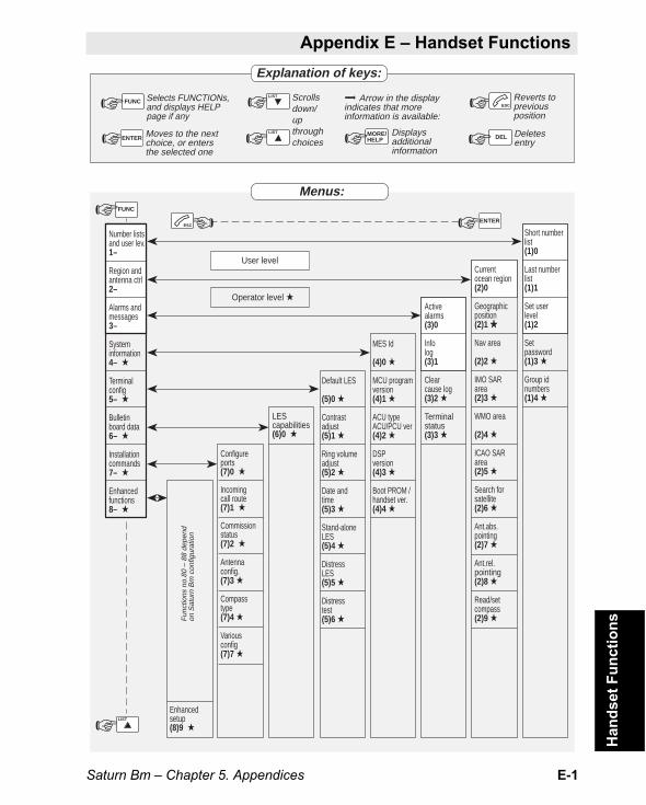
Saturn Bm – Chapter 5. Appendices E-1
Appendix E – Handset Functions
Han
dse
t F
un
ctio
ns
Number listsand user lev.1–
Region andantenna ctrl2–
Alarms andmessages3–
Systeminformation4– ★
Terminalconfig5– ★
Bulletinboard data6– ★
Installationcommands7– ★
Enhancedfunctions8– ★
User level
Operator level ★
MES Id
(4)0 ★
MCU programversion(4)1 ★
ACU typeACU/PCU ver(4)2 ★
DSPversion(4)3 ★
Boot PROM /handset ver.(4)4 ★
Enhancedsetup(8)9 ★
Activealarms(3)0
Infolog(3)1
Clearcause log(3)2 ★
Terminalstatus(3)3 ★
Menus:
Explanation of keys:
Reverts topreviousposition
Deletesentry
Scrollsdown/upthroughchoices
Displaysadditionalinformation
Arrow in the displayindicates that moreinformation is available:
Moves to the nextchoice, or entersthe selected one
Selects FUNCTIONs,and displays HELPpage if any
Currentocean region(2)0
Geographicposition(2)1 ★
Nav area
(2)2 ★
IMO SARarea(2)3 ★
WMO area
(2)4 ★
ICAO SARarea(2)5 ★
Search forsatellite(2)6 ★
Ant.abs.pointing(2)7 ★
Ant.rel.pointing(2)8 ★
Read/setcompass(2)9 ★
Default LES
(5)0 ★
Contrastadjust(5)1 ★
Ring volumeadjust(5)2 ★
Date andtime(5)3 ★
Stand-aloneLES(5)4 ★
DistressLES(5)5 ★
Distresstest(5)6 ★
LEScapabilities(6)0 ★
Configureports(7)0 ★
Incomingcall route(7)1 ★
Commissionstatus(7)2 ★
Antennaconfig.(7)3 ★
Compasstype(7)4 ★
Variousconfig(7)7 ★
Short numberlist(1)0
Last numberlist(1)1
Set userlevel(1)2
Setpassword(1)3 ★
Group idnumbers(1)4 ★
☞
☞
ENTER
ENTER
☞LIST
☞
☞
LIST
LIST MORE/HELP☞ DEL☞
☞ ESCFUNC☞
FUNC
☞ESC
☞
Fun
ctio
ns n
o.80
– 8
8 de
pend
on S
atur
n B
m c
onfig
urat
ion
Appendix E Handset Functions

Saturn Bm – Chapter 5. AppendicesE-2
ON
SHORT NUMBERLIST10
LAST NUMBERLIST11
SET USERLEVEL12
SETPASSWORD13
GROUP IDNUMBERS14
☞ ENTER
☞ ENTER
☞ ENTER SAT4✳00476684471
EIK4✳00470446222
INFO4✳00476684303
SEA210✳006577964
GBC2✳00448168655
NUMBER LISTSAND USER LEV.1–
Procedures:
LES_CODE210
EDIT MODE
SPC
AUX
☞
☞LIST
(Next entry e.g. no. 5)(Fullname+ more digits)
☞
(Fetches selectednumber for dialling.)
(or)
NERA AS00
EIK JORDSTAS50
INFOTEMA60
NERA SIN161
NERA LTD701
FULLNAMENERA LTD
ENTER FULLNAME
SHORTNAMEGBC
ENTER SHORTNAME
FULL NUMBER0044816865701
ENTER FULLNUMBER
NO VALUE =>DEFAULT LES
(or)
(or)
5MNO
ERASE
☞LIST
☞LIST
☞ FUNC
☞LIST ☞
☞
☞
☞
4✳0047668447004✳0047668447004✳0047044622504✳0047668430602✳30044816865701
☞LIST
☞LIST
Described inseparate manual
☞LIST
☞LIST
(Examples)
ID F796EBFLEET
ID F701FBFLEET
ID F432FBNATIONAL
☞ ENTER
☞ ENTER 1=USER2=OPERATOR
LEVEL:2 ❚
LEVEL:USER☞ ENTER LEVEL:
OPERATOR☞ ENTER2DEF
PLAY >
ENTER
ENTER
ENTER
ENTER
ENTER
LIST
LIST
LIST
For helppage
For page 2 To revert☞ FUNC ☞ ESC☞ MORE/HELP
Han
dset
Fun
ctio
ns C
ont’d
Appendix E – Handset Functions Cont’d

Saturn Bm – Chapter 5. Appendices E-3
ON
REGION ANDANTENNA CTRL2–
CURRENTOCEAN REGION20
OCEAN REGIONAOR–E 1
EDIT MODE COMMANDACCEPTED
COMMANDACCEPTED
COMMANDACCEPTED
COMMANDACCEPTED
COMMANDACCEPTED
COMMANDACCEPTED
COMMANDACCEPTED
COMMANDACCEPTED
ENT = SELECTAOR–W 0
ENT = SELECTAOR–E 1
ENT = SELECTPOR 2
ENT = SELECTIOR 3
ENT = SELECTREGION 4 4
ENT = SELECTREGION 5 5
ENT = SELECTREGION 6 6
ENT = SELECTREGION 7 7
☞ ☞ ☞ ☞
☞
☞
☞
☞
☞
☞
☞
For helppage
For page 2 To revert☞ FUNC ☞ ESC☞ MORE/HELP
☞LIST
☞LIST
☞LIST
ENTER ENTER ENTER ENTER
ENTER
ENTER
ENTER
ENTER
ENTER
ENTER
ENTER
EDIT MODEENTER☞
ENTER☞ ENTER☞
ENTER☞
ENTER☞ 6.0 KNOTS198 DEG
012d20.99É060d15.76´N
LONGITUDEE 010´15❚
DEG’ MIN✳=E, #=W
LATITUDEN 59´10❚
SPEED11❚
0 . . 255 KNOTS
HEADING210❚
0 . . 360 DEG
GEOGRAPHICPOSITION21
☞LIST
DEG’MIN✳=N, #=S
EDIT MODEENTER☞ENTER☞ DERIVEDFROM GEO.POS
NAVAREA : 1AREA: ALL
AREA✳❚
AREA=0 . . 253✳=ALL
NAVAREA
22
EDIT MODEENTER☞ENTER☞ DERIVEDFROM GEO.POS
IMO AREA : 1AREA: ALL
IMO SARAREA23
EDIT MODEENTER☞ENTER☞ DERIVEDFROM GEO.POS
WMO AREA : 1AREA: ALL
WMO AREA
24
EDIT MODEENTER☞ENTER☞ DERIVEDFROM GEO.POS
ICAO AREA : 1AREA: ALL
ICAO SARAREA25
AREA✳❚
AREA=0 . . 253✳=ALL
AREA✳❚
AREA=0 . . 253✳=ALL
AREA✳❚
AREA=0 . . 253✳=ALL
☞LIST
Han
dset
Fun
ctio
ns C
ont’d
Appendix E – Handset Functions Cont’d

Saturn Bm – Chapter 5. AppendicesE-4
ON
REGION ANDANTENNA CTRL2–
☞ ENTER
HEADING:322 DEG
For helppage
For page 2 To revert☞ FUNC ☞ ESC☞ MORE/HELP
Continued
☞LIST
☞LIST
HEADING:0 ❚
0 . . 360 DEGENTER☞ EDIT MODEENTER☞ ENTER☞READ/SETCOMPASS29
HEADING:275 DEG
AZIMUTH0 ❚
AZ. ANGLE0 . . 360 DEG
ELEVATION0 ❚
EL. ANGLE0 . . 90 DEG
ENTER☞ EL.ZONE: 0AZ.ZONE: 11
ENTER☞ EDIT MODE
ENTER☞COMMANDACCEPTED
ENTER☞
ENTER☞ ENTER☞ANT.ABSPOINTING27
EL: 77/AZ:250S/N: 86
EDIT MODEENTER☞
LIST
☞LIST
☞
SHIFT☞LIST
☞LIST
☞ ESC☞
EL.ZONE: 0AZ.ZONE: 11
ENTER☞ EL: 77/AZ:250S/N: 86
EL: 77/AZ:276S/N: 86CW
EL: 77/AZ:150S/N: 86CCW
EL: 56/AZ:250S/N: 86DWN
EL: 82/AZ:250S/N: 86UP
ANT.REL.POINTING28
EL: 77/AZ:250S/N: 86
SEARCH FORSATELLITE26
ENTER☞ PRESS ENTERTO SEARCH
ESC TO ABORT COMMANDACCEPTED
REQUESTING*******
ENTER☞
Han
dset
Fun
ctio
ns C
ont’d
Appendix E – Handset Functions Cont’d

Saturn Bm – Chapter 5. Appendices E-5
ON
SYSTEMINFORMATION4–
☞LIST
☞LIST
☞LIST
☞LIST
☞LIST
☞LIST
ENTER☞
MES ID
40
MCU PROGRAMVERSION41
ACU TYPEACU/PCU VER42
DSP PROMVERSION43
BOOT PROM /HANDSET VER.44
ENTER TOREAD
ENTER TOREAD
ENTER TOREAD
ENTER TOREAD
FWDID1❚
Rev.2.03SATURN B
Bm2.0 / NO PCU
Rev. 3.01SATURN B
028 / 1.40s1.8
(Example)
ON
ALARMS ANDMESSAGES3–
ACTIVEALARMS30
INFOLOG31
CLEARCAUSE LOG32
TERMINALSTATUS33
ACU FAILEDON9
ALONE LESOK11
ALONE LESUNSELECTED11
UPDATED LESCAPABILITIES200etc.
12B1/015.029311141417566
12B1/015.029311141405565
12B1/015.029311141405174etc.
RX SIGNALON0
TX1 LOCKON1
TX2 LOCKON2etc.
1993. 10. 1811 : 41 : 199
(Examples)
1993. 10. 1811 : 41 : 1911
1993. 10. 1810 : 31 : 0511
1993. 10. 1809 : 55 : 30200
ANTENNA LINKFAILURE6
ANTENNA LINKFAILURE5
ANTENNA LINKFAILURE4
(Examples)
(Part of terminalstatus list)
DEFAULT LESEX. 001
29 Sep 199513:52:58
1995-06-01
☞ ENTER
☞ ENTER
☞ ENTER☞ ENTER
☞ ENTER
☞ ENTER
☞LIST
☞LIST
☞LIST
ENTER☞
☞LIST
☞LIST
☞LIST
☞ ENTER ☞ ENTER
☞ ENTER
☞ ENTER
☞ ENTER ☞ ENTER
For helppage
For page 2 To revert☞ FUNC ☞ ESC☞ MORE/HELP
FWD: FC8884RTN: 4567
RETURNID2❚
DEFAULT LESEX. 002
Han
dset
Fun
ctio
ns C
ont’d
Appendix E – Handset Functions Cont’d

Saturn Bm – Chapter 5. AppendicesE-6
☞ ENTER
DEFCES_ID1 ❚
DEFAULT LESEX. 001
☞ ENTER
☞ ENTER
☞ ENTER
☞ ENTER
☞ ENTER
☞ ENTER
☞ ENTER
☞ ENTER
☞ ENTER
☞ ENTER
☞ ENTER
☞ ENTER☞ ENTER ☞ ENTER
☞ ENTER
☞ ENTER
☞ ENTER
☞ ENTER
☞ ENTER
☞ ENTER
☞ ENTER
☞ ENTER
☞ ENTER
☞ ENTER
☞ ENTER
CONTRASTADJUST51
RING VOLUMEADJUST52
DATEAND TIME53
CONTRAST:✳✳✳✳✳✳✳✳
RING VOLUME:✳✳✳✳
1994.09.2516:38:28SUN
EDIT MODE YEAR1994 ❚SUN
MONTH9 ❚SUN
DAY28 ❚SUN
DAYOFWEEK5 ❚SUN
HOUR15 ❚SUN
MINUTE46 ❚SUN
SECOND12 ❚SUN
SET TIME? ❚
(Reducescontrast)
(Increasescontrast)
(Reducessound level)
(Increasessound level)
(Setslevel)
(Setslevel)
YEAR=1901 . . 2099
MONTH=1 . . 12
DAY=1 . . 31
DAY OF WEEK=1 . . 7, 1=SUN
HOUR=0 . . 23
MINUTE=0 . . 59
SECOND=0 . . 59
PRESS ENTERTO SET CLOCK
1994:09:2815:46:12
AOR–ELES 21
PORLES 02
IORLES 03
REGION 4LES 04
REGION 5LES 05
REGION 6LES 06
REGION 7LES 07
EDIT MODEDEFAULT LES
50
AOR–WLES 10
EDIT MODE
EDIT MODE
EDIT MODE
EDIT MODE
EDIT MODE
EDIT MODE
EDIT MODE
CLOCK SET= ↔SYSTEM RESTART
Example
AOR–WLES 00
ON
TERMINALCONFIG5–
☞LIST
☞LIST
☞LIST
☞LIST
☞LIST
☞LIST
☞LIST
☞LIST
☞ ESC
☞LIST
For helppage
For page 2 To revert☞ FUNC ☞ ESC☞ MORE/HELP
Appendix E – Handset Functions Cont’dH
ands
et F
unct
ions
Con
t’d

Saturn Bm – Chapter 5. Appendices E-7
Appendix E – Handset Functions Cont’d
Han
dset
Fun
ctio
ns C
ont’d
☞ ENTER ALONE LES0 ❚
STANDALONELES☞ ENTER ☞ ENTER
☞ ENTER
☞ ENTER
☞ ENTER
☞ ENTER
☞ ENTER
☞ ENTER
☞ ENTER
☞ ENTER
EDIT MODE
EDIT MODE
EDIT MODE
EDIT MODE
EDIT MODE
EDIT MODE
EDIT MODE
STAND-ALONELES54
Continued
AOR–ELES 21
PORLES 02
IORLES 03
REGION 4LES 04
REGION 5LES 05
REGION 6LES 06
REGION 7LES 07
EDIT MODE AOR–WLES 00
Example
AOR–WLES 00
ON
TERMINALCONFIG5–
☞LIST
☞LIST
☞ ESC☞ ESC
☞ ESC
EDIT MODE AOR–WLES 00
☞LIST
☞LIST
DISTRESSTEST56
☞ ENTER ☞ ENTER☞ ENTER
REALDISTRESS☞ ENTER ☞ ENTER TEST
DISTRESSENTER FORTEST DIST.
ENTER FORREAL DIST.
DISTRESS LES0 ❚
PREFERREDLES
Example
AOR–WLES 00
AOR–ELES 21
PORLES 02
IORLES 03
REGION 4LES 04
REGION 5LES 05
REGION 6LES 06
REGION 7LES 07
☞LIST
☞LIST
☞ ENTER
☞ ENTER
☞ ENTER
☞ ENTER
☞ ENTER
☞ ENTER
☞ ENTER EDIT MODE
EDIT MODE
EDIT MODE
EDIT MODE
EDIT MODE
EDIT MODE
EDIT MODE
DISTRESSLES55
For helppage
For page 2 To revert☞ FUNC ☞ ESC☞ MORE/HELP

Saturn Bm – Chapter 5. AppendicesE-8
Appendix E – Handset Functions Cont’dH
ands
et F
unct
ions
Con
t’d
☞ ENTER
☞ ENTER
☞ ENTER
☞ ENTER
☞ ENTER
☞ ENTER
☞ ENTER
☞ ENTER☞ ENTER ☞ ENTERVALID VALUEIS 0 . . 7
ON
BULLETINBOARD DATA6–
LESCAPABILITIES60
CONFIGUREPORTS70
HANDSETPHONE
TEL.1PHONE
TEL.2FAX
TEL.3NOTHING
TEL.4NOTHING
TEL.5NOTHING
TELEXINSTALLED
ENTER☞
☞LIST
☞LIST
ENT = SELECTAOR–W 0
ENT = SELECTAOR–E 1
ENT = SELECTPOR 2
ENT = SELECTIOR 3
ENT = SELECTREGION 4 4
ENT = SELECTREGION 5 5
ENT = SELECTREGION 6 6
ENT = SELECTREGION 7 7
☞LIST
☞LIST
☞LIST
☞LIST
☞ ESC
ENTER☞ ENTER☞
ENTER☞
ENTER☞
ENTER☞
ENTER☞
ENTER☞
ENTER☞
ENTER☞
VFD, DI, DT
VFD, DI, DT
VFD, DI, DT,
VFD, DI, DT
IOR001 / 43
IOR003 / 43
IOR004 / 93
IOR011 / 153
For helppage
For page 2 To revert☞ FUNC ☞ ESC☞ MORE/HELP
☞ ENTER
TERMTYPE1 ❚
1=TPH2=FAXEDIT MODE
☞ ENTER
☞LIST
☞LIST
☞LIST
VALID VALUEIS 0 . . 99
ORGTERMID1 ❚
ON
INSTALLATIONCOMMANDS7–
OI = 1DAU ID = 0
OI = 2DAU ID = 1
OI = 17
OI = 0
OI = 0
OI = 0
OI= 49
DISTRESS_ID0 ❚

Saturn Bm – Chapter 5. Appendices E-9
Appendix E – Handset Functions Cont’d
Han
dset
Fun
ctio
ns C
ont’d
☞ ENTER RING H12345PON 1✳✳✳✳✳1
RING H12345PON ✳1✳✳✳✳2
RING H12345PON ✳✳1✳✳✳17
49
☞ ENTER ☞ ENTER
ENTER☞ENTER☞ COMPASS:1 ❚
1=360, 2=1803=90, 4=NAVEDIT MODE ENTER☞ COMPASS:
RATIO_1_360
ENTER☞ DEF. PRINTER3 ❚
0=NO, 2=PRINT3=DTE PORTEDIT MODEMSGIND: 111
NO NMEAENTER☞
ENTER☞ ENTER☞
POS.SOURCE0 ❚
0=MANUAL POS2=NMEA INPUT
COMBO1 ❚
1=DISABLED2=ENABLED
ENTER☞
SERV.ANN.PRN2 ❚
0=NO, 1=TO PC2=PRNT, 3=DTE
FTD (MSGIND)111 ❚
F=FAX, T=TLXD=DATA
ENTER☞
INCOMINGCALL ROUTE71
TELEPHONY
1
TELEPHONY
2
FACSIMILE
17
TELEX
49
ON
INSTALLATIONCOMMANDS7–
EDIT MODEENTER☞
ENTER☞ ENTER☞
ENTER☞ ENTER☞
ENTER☞ AZIMUTH_ONLYREGION_FREQS EDIT MODEENTER☞ON/ENABLED
30ANTENNACONFIG73
TRACKING0 ❚
0=OFF1=ON
HPA_DISABLE0 ❚
0=ENABLE1=DISABLE
TIMEOUT_TIME30 ❚
TIME0 . . 1440
INIT_SWEEP1 ❚
VALID VALUEIS 0 . . 5
AUTO_SWEEP3 ❚
VALID VALUEIS 0 . . 5
TRACKING0 ❚
0=OFF1=ON
☞ ENTER ☞ ENTER ENTER TOPASSIFY
COMMISSIONSTATUS72
COMMISSIONACTIVE
ENTER TOACTIVATE
COMMISSIONNOT ACTIVE☞
LIST
COMPASS:RATIO_1_360
COMPASSTYPE74
VARIOUSCONFIG77
☞LIST
TO PRINTERTO PC
For helppage
For page 2 To revert☞ FUNC ☞ ESC☞ MORE/HELP
Audio ports only
Continued
☞ ENTER
☞ ENTER
☞ ENTER
☞ ENTER
☞LIST
1=RING ON✳=NO RING1
H12345P1✳✳✳✳✳ ❚1
1=TPH, 2=FAX4=TLX, 5=HSD1
SERVICE1 ❚1
☞LIST
EDIT MODE
☞ ENTER

Saturn Bm – Chapter 5. AppendicesE-10
Appendix E – Handset Functions Cont’dH
ands
et F
unct
ions
Con
t’d
☞ ENTER
ENTER☞WHICH LINES14 ❚
0=HANDSET1–5=TEL 1–5
CHARGE TONES LINES 14 ❚
OPER.– –
ENTER☞ENTER☞STATUS OPER.3 ❚
2=OPERATOR3=RENT, 4=OWN
ON
ENHANCEDFUNCTIONS8–
☞LIST
ENHANCEDSETUP89
CHARGE TONEPASSIVE
OPER.– –
ENTER☞ EDIT MODE☞LIST
☞LIST
For helppage
For page 2 To revert☞ FUNC ☞ ESC☞ MORE/HELP
Functions no.80 – 88 dependon Saturn configuration

F-1Saturn Bm – Chapter 5. Appendices
Con
figur
atio
n Ta
bles
IMN DI CommentsConnectors on MCU
InmarsatMobileNumber
Ringing ON: 1 / Ringing OFF:
Ser-vice
ROUTING OF INCOMING CALLS
PORT CONFIGURATION
Connector Service
OriginatingIdentificationdigits
CommentsOI
HANDSET
TEL.1
TEL.2
TEL.3
TEL.4
TEL.5
1=TPH2=FAX4=TLX5=HSD
Des
tinat
ion
Iden
tific
atio
n di
gits
Tele
phon
e =
1, T
elef
ax =
2Te
lex
= 4,
HS
D =
5
HDST TEL.1 TEL.2 TEL.3 TEL.4 TEL.5 PC DTE
PC
DTE
ON
RING H12345PON 11
Appendix F – Configuration Tables
Appendix F Configuration Tables


G-1Saturn Bm – Chapter 5. Appendices
AOR-E Atlantic Ocean Region East.
AOR-W Atlantic Ocean Region West.
AZIMUTH horizontal direction angle between north and, e.g. thedirection to the satellite.
ASCII American Standard Code for Information Interchange, a stand-ard character encoding scheme widely used in computers and com-munications. Defined as a 7-bit code character presentation (same asIA5 by CCITT). An industry version of 8-bit extended ASCII is oftenused.
BER Bit Error Rate
BPSK Binary Phase Shift Keying
Bulletin Board system status information for MES.
C Band band of radio frequencies from about 4.0 GHz to 6.0 GHz,used by the Inmarsat-B links between fixed NCS/LES and the satel-lite.
CCITT The International Telephone and Telegraph ConsultativeCommittee, the organisation within the ITU that sets the standards forterrestrial networks.
Centronics industry standard parallel I/O interface.
Codec speech encoder/decoder
Commissioning process following initial MES registration with Inmar-sat that includes test of MES and certifies it for operation.
Deg degrees
DI/DID Destination Identification Digits, number actually used by thesystem to route incoming calls to the individual Saturn B end termi-nals.
DNIC Data Network Identification Code.
Downlink radio link from the satellite down to stations on Earth.
DTMF Dual-Tone Multifrequency Dialing, pulsing in which each digitis represented by a specific pair of audio frequencies (one tone below1000 Hz and another above 1200 Hz).
Elevation vertical angle to the satellite, e.g. the height of the satelliteabove the horizon.
End terminal physical device connected to one of the MES connec-tors, e.g. telephone or telefax.
FleetNET™ an EGC service for commercial messages to individualusers or groups of users. L
ist
of
Ter
ms
Appendix G – List of Terms
List of TermsAppendix G

G-2 Saturn Bm – Chapter 5. Appendices
Geostationary position of satellite approximately 36,000 km abovethe surface of the Earth at the equator; satellite rotates with Earth andtherefore appears fixed in space.
Group Calls an EGC service that enables many MESs to receivesame message.
HPA High Power Amplifier
ID Identification Digit(s)
IMN Inmarsat Mobile Number, a unique 9-digit number which identi-fies each end terminal of Saturn B.
Inmarsat International Maritime Satellite Organisation
IOR Indian Ocean Region.
ISDN Integrated Services Digital Network, digital national and interna-tional telecommunications network.
ISN Inmarsat Serial Number, individual number assigned to eachSaturn B station.
ITU International Telecommunications Union, international organisa-tion that oversees and compiles standards for telecommunications.
L Band band of radio frequencies from about 1.5 GHz to 1.6 GHz,used by the Inmarsat-B links between MES and the satellite.
Latitude distance north or south of the equator, measured in de-grees.
LED Light-Emitting Diode, semiconductor element that emits light.
LES Land Earth Station, a station that interconnects fixed telecommu-nications networks with the Inmarsat system; may also be called aCES (Coast Earth Station) or a GES (Ground Earth Station).
LESA Land Earth Station Assignment Channel
LESI Land Earth Station Interstation Signalling Channel
LHCP Left Hand Circular Polarization
LONG longitude
LNA Low Noise Amplifier
Longitude distance east or west of Greenwich meridian, measured indegrees.
MCC Mobile Country Code
MCU Main Control Unit, major part of terminal; performs all signalprocessing and message handling functions.
MES Mobile Earth Station, a user terminal for an Inmarsat system;the Saturn M terminal is an MES for the Inmarsat-B system; MESLi
st o
f Ter
ms
Con
t’dAppendix G – List of Terms Cont’d
G-3Saturn Bm – Chapter 5. Appendices
may also be called SES (Ship Earth Station) or, if on aircraft, AES(Aeronautical Earth Station).
MID Maritime Identification Digits
MSI Maritime Safety Information, urgent safety-related messagestransmitted via EGC.
NAVAREA , sea area of the world for Coastal Warnings; total of 16(also called MSI area).
NCS Network Coordination Station, station that supervises all mes-sages and signals sent in the Inmarsat system; one in each OceanRegion.
NCSC time-division multiplex (TDM) channel used in the forwarddirection to carry NCS signalling messages including Call Announce-ments, network Status Information (Bulletin Board) and selectivechannel clearing.
NMEA National Marine Electronics Association, US industrial organi-sation whose activities include stipulating standards for marine navi-gation systems.
OCC Operation Control Centre, Inmarsat centre that monitors entireInmarsat system.
Ocean Region area of coverage of a single Inmarsat satellite, from70°N to 70°S; there are four: Atlantic East, Atlantic West, Pacific,Indian.
OI/OID Originating Identification Digits, number used by the system toidentify the end terminal making outgoing calls (for billing purposes).
O-QPSK Offset Quadrature Phase Shift Keying.
PC Personal Computer
POR Pacific Ocean Region
Prefix service in Inmarsat-B, two-digit prefix to number called, keyedin to stipulate special service, such as credit-card call.
Protocol the internal rules in the system that enable communications.
PSDN Packet Switched Data Network, terrestrial network for packetdata communications.
PSTN Public Switched Telephone Network, terrestrial network fortelephone, telefax and data modem services.
PTT Push-To-Talk
RCC Rescue Coordination Centre
RHCP Right Hand Circular Polarization
List
of T
erm
s C
ont’d
Appendix G – List of Terms Cont’d

G-4 Saturn Bm – Chapter 5. Appendices
ROM Read-Only Memory, microchip memory that stores fixed pro-grams.
Rx Receive.
SAR Search And Rescue, organisations that perform search andrescue at sea; usually have land base that often is interconnected toInmarsat systems.
SCC Satellite Control Centre
SCPC Single Channel per Carrier
SDM (Inmarsat) System Definition Manual
Spot Beam (Inmarsat-B) service that divides each Ocean Region intosub-regions, each “spotlighted” by a beam from the region satellite;permits increasing capacity of system.
SU Signalling Unit, 96-bit data packets used to conduct user-to-usersystem signalling.
TDM Time Division Multiplexing, method of allowing several users toshare the same channel.
TDMA Time Division Multiple Access
Terrestrial Network a fixed telecommunications network, such as atelephone network or a data network, which connects to the Inmarsat-B system at an LES/NCS.
TUP Telephone User Part of CCITT Signalling System No 7.
Tx Transmit
Uplink radio link from a station on Earth up to the satellite.
UTC Coordinated Universal Time, referenced to Greenwich MeanTime (GMT)
UW Unique Word
WMO World Meteorological Organization
X.25 type of data network protocol, known as message switched, asmessages are transferred in packets.
X.400 type of data network protocol, known as message switches asentire messages are compiled and transmitted as units; includesservices such as electronic mail.
List
of T
erm
s C
ont’d
Appendix G – List of Terms Cont’d

H-1Saturn Bm – Chapter 5. Appendices
MC
U M
ain
ten
ance
Appendix H – MCU Maintenance
MCU MaintenanceAppendix H
Saturn B
Air int
ake
The air intake for the Main Control Unit cooling fan must be cleanedfrom time to time to prevent overheating.
Use a vacuum cleaner and cloth.


Saturn Bm – Operator’s Manual
AAbbreviated dialing 2.9Above Deck Equipment 1.3, 4.3Absolute pointing 2.29Access level 2.17Active alarms 2.13ADE 1.3, 4.3Alarm messages
list of D-1, D-2, D-3, D-4ALPHA function 2.2Antenna
absolute pointing 2.29azimuth angle 2.27configuration 2.22, 2.23, 3.10pointing 2.28, 4.8
Antenna Control Unit, ACU 1.3Arrow keys 2.3Auto
search 2.22, 3.10, 4.10tracking 2.22, 3.10
Azimuth G-1angle 4.9limit area 2.27map A-4search 2.22
BBank services 2.3Basic parts 1.1BDE 1.1, 4.3Below Deck Equipment 1.1, 4.3
CCabling diagram C-1Call 1.10Call duration 2.4Call route. See Incoming call routeCapabilities of LES 3.5CCITT G-1Clear causes
log 2.15Commissioning
term G-1Communication
description 4.3path 4.3services 4.4, 4.6
Compass source 3.9Configuration
tables F-1Configuring ports
default services 3.11deleting services 3.13selecting services 3.12
Connector panel 1.15
Contrast 3.1Country codes 4.6
DDate & time
setting on handset 3.3Default LES
selection of 2.18selection of distress LES 3.7
Default services 3.11Destination Id (DI) 3.11, 3.12, G-1Direct-to-Satellite Search 2.23Display Handset 1.2
contrast 3.1light on/off 2.2switches and indicators 1.6
DistressAlarm 1.2, 2.31programming Alarm Unit 3.12selection of LES 3.7test 2.31, 3.8
Duration of a call 2.4
EElevation G-1
angle 4.9End terminal G-1
deleting service of 3.13selecting service of 3.12
Entering short numbers 2.10Escape key 2.1
FFunctions
list of 2.6overview E-1
Functions:Absolute pointing 2.29Active alarms 2.13ACU type / ACU/PCU ver. 2.19Antenna configuration 3.10Antenna relative pointing 2.28Area group calls 3.4BOOT PROM and handset ver. 2.19Clear cause log 2.15Compass type 3.9Configuring ports 3.12, 3.13, 3.14Distress test 3.8DSP version 2.19Geographic position 2.21Group calls 2.20Heading input 2.26Info log 2.14Last number redialing 2.12LES capabilities 3.5MCU program version 2.19MES ID 2.19
Ind
ex
Index

Saturn Bm – Operator’s Manual
Read/set compass 2.26Relative pointing 2.28Satellite search 2.22Selecting default distress LES 3.7Selecting default LES 2.18Selecting Ocean Region 2.8Selecting stand-alone LES 3.6Setting date & time 3.3Setting display contrast 3.1Setting ringing volume 3.2Setting user level 2.17Terminal status 2.16Various configurations 3.21
GGeographic position 2.21Geostationary orbit 4.2Gyro 2.26Gyro input data 1.8
HHandset version 2.19Heading input 2.26Hemispheric search 2.23Hexadecimal numbers 3.12
IIdentification numbers 2.18Idle mode 2.1ILLEGAL CHOICE message 2.18Illumination
of display and keys 2.1, 2.2IMN
Inmarsat Mobile Number G-2Incoming call route
changing 3.20check settings 3.18deleting 3.16extended 3.15extended routing 3.19routing table 3.17, F-1
Indicatorson display handset 1.6
Info log 2.14Initial search 2.22, 4.10
level 3.10Inmarsat G-2
description of 4.1Mobile Number 3.11overview of system 4.1
International codes 4.6ISN G-2
KKey light 2.2Keying letters 2.3Keypad 1.6
LLand Earth Station, LES 4.1
description G-2list of A-2, A-3
Last numberfetching 2.12redialing function 2.12
Latitude G-2LES 4.1
capabilities 3.5default distress 3.7selecting default 2.18selecting stand-alone 3.6
Letters, typing of 2.3Light intensity 2.2, 3.1List of functions 2.6Longitude G-2Loudspeaker 2.1
MMain Control Unit 1.2MCU 1.2
connector panel 1.15Menus
Display Handset 2.6MES 4.1
description G-2Message Indicator 2.30
configuration of 3.21Mobile Earth Station 4.1, G-2Mobile-to-LES Call 4.4
NNCS 4.1NCSC 2.22
frequency 4.12Network Coordinating Station 3.6, 4.1
description G-3NMEA-0183 G-3
input selection 3.21
OOcean Region 4.2, G-3
codes 4.6current 2.8selecting 2.8
OID. See Originating IDOperational Area 2.27Operator level 2.5, 2.17Originating Id (OI) 3.11, 3.12, G-3
PPersonal Computer, PC 1.3Pointing antenna 2.28Ports. See Configuring ports: default services
configuring 3.11
Ind
ex C
on
t’d
Index Cont’d

Saturn Bm – Operator’s Manual
PowerON/OFF switch 1.15supply 1.2
Prefix service G-3Printouts 3.22Program version 2.19Push-To-Talk 2.1
RRadome 1.3Redialing last number 2.12Relative pointing 2.28Rewind area 2.27Ringing volume, setting 3.2Routing Table 3.17
SSatellite
altitude 4.2automatic searching 2.22, 4.10coverage map 2.8, A-1geostationary positions 4.2initiate searching 1.8manually initiated search 2.25NCSC frequency 4.12positions 4.2search 2.22search levels 2.22, 4.12search patterns 4.10
Saturn Bmoverview 1.1
Scrolling 2.3Search
levels 3.10, 4.12patterns 4.10
Self-test 1.7Service
address calls 1.12announcements 3.21
Services 3.11, 3.12, 3.13
Settingdate & time 3.3
Ship’sheading 4.8plotted position 4.8
Short numberserasing 2.11
Shortcuts 2.5Signal
/noise ratio 2.28quality indication 1.9strength 1.9
Spot beamterm G-4
Stand-alone LES 3.6Starting Up 1.7System
description 4.1information menu 2.19
TTelefax 1.3
transmission rate 1.14Telephone 1.2
explanation of codes B-1list of country codes B-2, B-4special services codes B-5
Termslist of G-1
Time and date, setting 3.3
UUser
levels 2.5setting of level 2.17
VVersions 2.19Voice letters 2.3Volume 3.2
Index Cont’d
Ind
ex C
on
t’d


Nera SatCom ASMarine & MobileP.O.Box 91, N-1375 BILLINGSTAD, NorwayPhone: +47 67 24 47 00Telex: 71721 umeb nTelefax: +47 67 24 46 21Website: http://www.nera.satcom.no