SAR/SCBA SS600-AN-MMA-010 Chapter 2 - DCPPE SS600-AN-MMA-010 Chapter 2 Table 2-6. SAR/SCBA Operating...
20
SAR/SCBA SS600-AN-MMA-010 Chapter 2 Table 2-6. SAR/SCBA Operating Procedures - Continued Step Procedure Revision 2 2-21 WARNING WARNING 16. Remove facepiece and doff the SCBA unit when "safe" area is reached. If working in a contaminated atmosphere or if user is exposed to contaminants while in work area, take proper precautions to decontaminate facepiece and head area prior to doffing facepiece. User must determine potential risk and take necessary precautions. Failure to follow this warning could result in serious injury or death. a. Loosen headband harness straps so that all ends are near their respective buckles. b. Depress semiautomatic push button (don/doff) on side of MMR to stop flow of air into facepiece. c. Lift facepiece away from face and remove from head. d. Close the SCBA air cylinder valve, if it was opened for emer- gency escape. e. Unbuckle waist belt and lift shoulder strap over head to remove SCBA unit. f. Remove Navy-approved body harness. g. Clean and sanitize facepiece before storing. See Table 2-7, SAR/SCBA Post-Operational Procedures. SHUT-DOWN PROCEDURES 17. Shut down HP air to PASP. Turn three-way ball valve (AHP-V204) to center (closed) position. 18. Shut down HP air cylinders. Turn HP air cylinder valves ( AHP-V201, AHP-V301 and/or AHP- V302) fully CW until valve(s) seat. 19. Bleed (open) LP manifold bleed valve (ALP- V208). Before bleeding (opening) LP manifold bleed valve (ALP-V208), ensure all personnel stand clear of area to avoid injury from flying debris. Operator shall announce "Bleeding down" to warn nearby personnel. Operator must wear protective eye wear when bleeding system to prevent eye injuries or blindness. a. Turn ALP-V208 CW and hold open until both gauges read zero. b. Release ALP-V208. It will snap shut automatically, moving CCW. c. Both gauges (AHP-G201, ALP-G202) should read zero.
Transcript of SAR/SCBA SS600-AN-MMA-010 Chapter 2 - DCPPE SS600-AN-MMA-010 Chapter 2 Table 2-6. SAR/SCBA Operating...
SAR/SCBA SS600-AN-MMA-010 Chapter 2
Table 2-6. SAR/SCBA Operating Procedures - Continued
Step Procedure
Revision 2 2-21
WARNING
WARNING
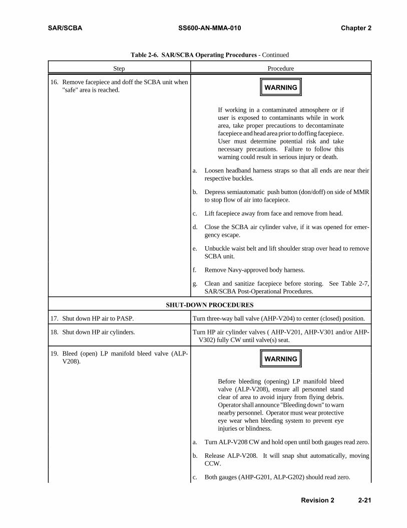
16. Remove facepiece and doff the SCBA unit when"safe" area is reached.
If working in a contaminated atmosphere or ifuser is exposed to contaminants while in workarea, take proper precautions to decontaminatefacepiece and head area prior to doffing facepiece.User must determine potential risk and takenecessary precautions. Failure to follow thiswarning could result in serious injury or death.
a. Loosen headband harness straps so that all ends are near theirrespective buckles.
b. Depress semiautomatic push button (don/doff) on side of MMRto stop flow of air into facepiece.
c. Lift facepiece away from face and remove from head.
d. Close the SCBA air cylinder valve, if it was opened for emer-gency escape.
e. Unbuckle waist belt and lift shoulder strap over head to removeSCBA unit.
f. Remove Navy-approved body harness.
g. Clean and sanitize facepiece before storing. See Table 2-7,SAR/SCBA Post-Operational Procedures.
SHUT-DOWN PROCEDURES
17. Shut down HP air to PASP. Turn three-way ball valve (AHP-V204) to center (closed) position.
18. Shut down HP air cylinders. Turn HP air cylinder valves ( AHP-V201, AHP-V301 and/or AHP-V302) fully CW until valve(s) seat.
19. Bleed (open) LP manifold bleed valve (ALP-V208).
Before bleeding (opening) LP manifold bleedvalve (ALP-V208), ensure all personnel standclear of area to avoid injury from flying debris.Operator shall announce "Bleeding down" to warnnearby personnel. Operator must wear protectiveeye wear when bleeding system to prevent eyeinjuries or blindness.
a. Turn ALP-V208 CW and hold open until both gauges read zero.
b. Release ALP-V208. It will snap shut automatically, movingCCW.
c. Both gauges (AHP-G201, ALP-G202) should read zero.
Chapter 2 SS600-AN-MMA-010 SAR/SCBA
Table 2-6. SAR/SCBA Operating Procedures - Continued
Step Procedure
2-22 Revision 2
WARNING
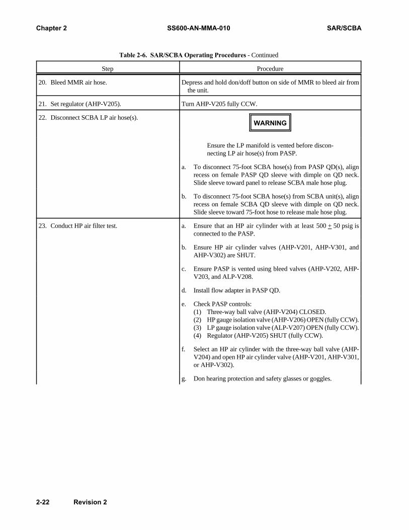
20. Bleed MMR air hose. Depress and hold don/doff button on side of MMR to bleed air fromthe unit.
21. Set regulator (AHP-V205). Turn AHP-V205 fully CCW.
22. Disconnect SCBA LP air hose(s).
Ensure the LP manifold is vented before discon-necting LP air hose(s) from PASP.
a. To disconnect 75-foot SCBA hose(s) from PASP QD(s), alignrecess on female PASP QD sleeve with dimple on QD neck.Slide sleeve toward panel to release SCBA male hose plug.
b. To disconnect 75-foot SCBA hose(s) from SCBA unit(s), alignrecess on female SCBA QD sleeve with dimple on QD neck.Slide sleeve toward 75-foot hose to release male hose plug.
23. Conduct HP air filter test. a. Ensure that an HP air cylinder with at least 500 + 50 psig isconnected to the PASP.
b. Ensure HP air cylinder valves (AHP-V201, AHP-V301, andAHP-V302) are SHUT.
c. Ensure PASP is vented using bleed valves (AHP-V202, AHP-V203, and ALP-V208.
d. Install flow adapter in PASP QD.
e. Check PASP controls:(1) Three-way ball valve (AHP-V204) CLOSED.(2) HP gauge isolation valve (AHP-V206) OPEN (fully CCW).(3) LP gauge isolation valve (ALP-V207) OPEN (fully CCW).(4) Regulator (AHP-V205) SHUT (fully CCW).
f. Select an HP air cylinder with the three-way ball valve (AHP-V204) and open HP air cylinder valve (AHP-V201, AHP-V301,or AHP-V302).
g. Don hearing protection and safety glasses or goggles.
SAR/SCBA SS600-AN-MMA-010 Chapter 2
Table 2-6. SAR/SCBA Operating Procedures - Continued
Step Procedure
Revision 2 2-23
WARNING
WARNING
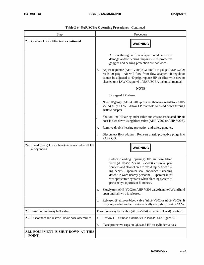
23. Conduct HP air filter test. - continued
Airflow through airflow adapter could cause eyedamage and/or hearing impairment if protectivegoggles and hearing protection are not worn.
h. Adjust regulator (AHP-V205) CW until LP gauge (ALP-G202)reads 40 psig. Air will flow from flow adapter. If regulatorcannot be adjusted to 40 psig, replace HP air filter with new orcleaned unit IAW Chapter 6 of SAR/SCBA technical manual.
NOTE
Disregard LP alarm.
i. Note HP gauge (AHP-G201) pressure, then turn regulator (AHP-V205) fully CCW. Allow LP manifold to bleed down throughairflow adapter.
j. Shut on-line HP air cylinder valve and ensure associated HP airhose is bled down using bleed valve (AHP-V202 or AHP-V203).
k. Remove double hearing protection and safety goggles.
l. Disconnect flow adapter. Reinsert plastic protective plugs intoPASP QD.
24. Bleed (open) HP air hose(s) connected to all HPair cylinders.
Before bleeding (opening) HP air hose bleedvalve (AHP-V202 or AHP-V203), ensure all per-sonnel stand clear of area to avoid injury from fly-ing debris. Operator shall announce "Bleedingdown" to warn nearby personnel. Operator mustwear protective eyewear when bleeding system toprevent eye injuries or blindness.
a. Slowly turn AHP-V202 or AHP-V203 valve handle CW and holdopen until all wire is released.
b. Release HP air hose bleed valve (AHP-V202 or AHP-V203). Itis spring-loaded and will automatically snap shut, turning CCW.
25. Position three-way ball valve. Turn three-way ball valve (AHP-V204) to center (closed) position.
26. Disconnect and restow HP air hose assemblies. a. Restow HP air hose assemblies in PASP. See Figure 8-8.
b. Place protective caps on QDs and HP air cylinder valves.
ALL EQUIPMENT IS SHUT DOWN AT THISPOINT.

Chapter 2 SS600-AN-MMA-010 SAR/SCBA
2-24 Revision 2
CAUTION
Table 2-7. SAR/SCBA Post-Operational Procedures
Step Procedure
1 If exposed to salt air environment or dirt, wipe down all equipment using fresh water.
2 Inspect equipment for damage, such as cracks, dents, punctures, and abrasions.
3 Ensure that exteriors of all hoses are clean and dry.
4 Ensure all equipment is clean and dry prior to storage. Clean and sanitize SCBA facepiece.
5 Refill PASP, RASP, and SCBA air cylinders IAW Tables 2-8 and 2-9.
6 Ensure all post-operational maintenance has been performed IAW PMS requirements. Post operationalmaintenance includes cleaning and inspecting all SAR/SCBA equipment.
Table 2-8. Procedures for Refilling PASP/RASP HP Air Cylinders
Step Procedure
1
Do not recharge an HP air cylinder that requires mainte-nance or if any damage to fiberglass overwrap is evident.
Check expiration date and inspect external surfaces.
2 Orient cylinder in PASP or RASP so that charging connection is easily accessible. Ensure cylinder is stabilized.
3 Remove protective cylinder valve cap. Attach CGA-347 nut on charging hose to cylinder valve connection.
4 Ensure charging hose is connected to a source of Grade D (or higher) HP air (dew point -65EF or lower).
5 Slowly open cylinder valve to pressurize charging hose, then open valve at least two turns.
6 Shut air source charging valve when charging pressure reaches 4,500 psig. Verify air cylinder pressure indicatorreads 4,500 psig.
NOTE
PASP/RASP HP air cylinders may be recharged to 3,000psig in event 4,500 psig air unavailable. The lower airpressure will result in reduced cylinder capacity (see Table3-1).
7 Shut air cylinder valve and bleed charging hose.
8 Remove charging hose from cylinder valve connection and reinstall protective cylinder valve cap.
SAR/SCBA SS600-AN-MMA-010 Chapter 2
Revision 2 2-25
CAUTION
WARNING
WARNING
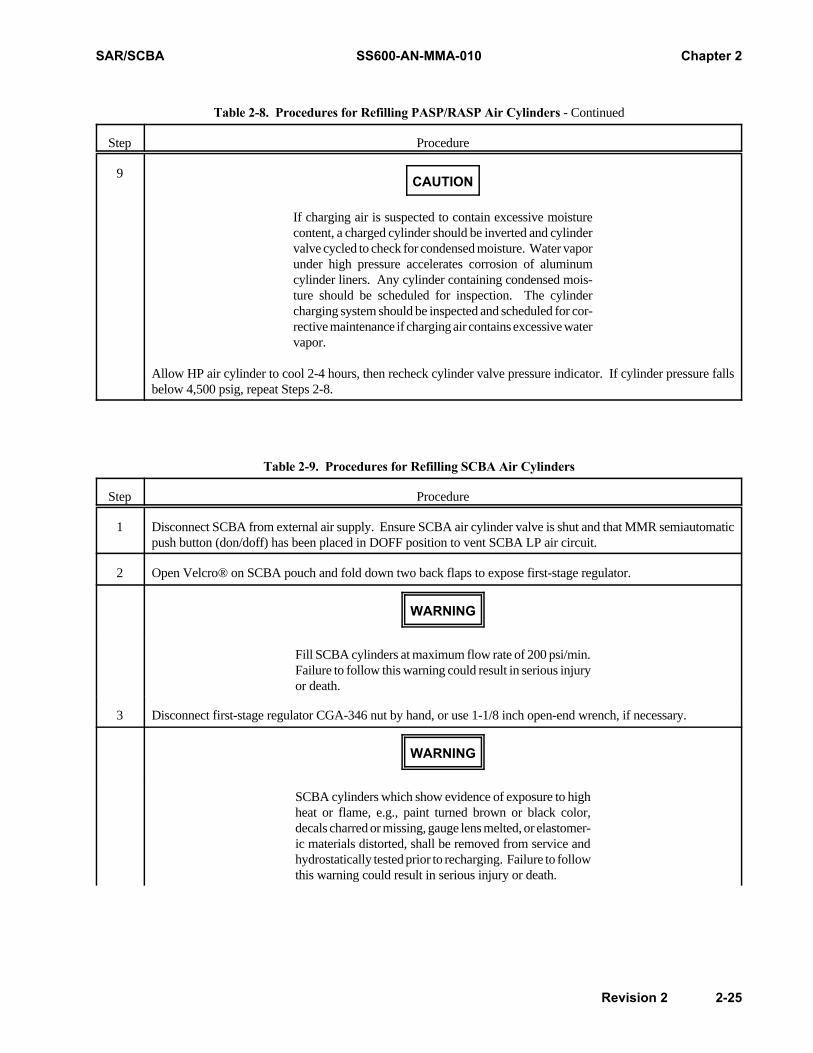
Table 2-8. Procedures for Refilling PASP/RASP Air Cylinders - Continued
Step Procedure
9
If charging air is suspected to contain excessive moisturecontent, a charged cylinder should be inverted and cylindervalve cycled to check for condensed moisture. Water vaporunder high pressure accelerates corrosion of aluminumcylinder liners. Any cylinder containing condensed mois-ture should be scheduled for inspection. The cylindercharging system should be inspected and scheduled for cor-rective maintenance if charging air contains excessive watervapor.
Allow HP air cylinder to cool 2-4 hours, then recheck cylinder valve pressure indicator. If cylinder pressure fallsbelow 4,500 psig, repeat Steps 2-8.
Table 2-9. Procedures for Refilling SCBA Air Cylinders
Step Procedure
1 Disconnect SCBA from external air supply. Ensure SCBA air cylinder valve is shut and that MMR semiautomaticpush button (don/doff) has been placed in DOFF position to vent SCBA LP air circuit.
2 Open Velcro® on SCBA pouch and fold down two back flaps to expose first-stage regulator.
Fill SCBA cylinders at maximum flow rate of 200 psi/min.Failure to follow this warning could result in serious injuryor death.
3 Disconnect first-stage regulator CGA-346 nut by hand, or use 1-1/8 inch open-end wrench, if necessary.
SCBA cylinders which show evidence of exposure to highheat or flame, e.g., paint turned brown or black color,decals charred or missing, gauge lens melted, or elastomer-ic materials distorted, shall be removed from service andhydrostatically tested prior to recharging. Failure to followthis warning could result in serious injury or death.
Chapter 2 SS600-AN-MMA-010 SAR/SCBA
2-26 Revision 2
WARNING
CAUTION
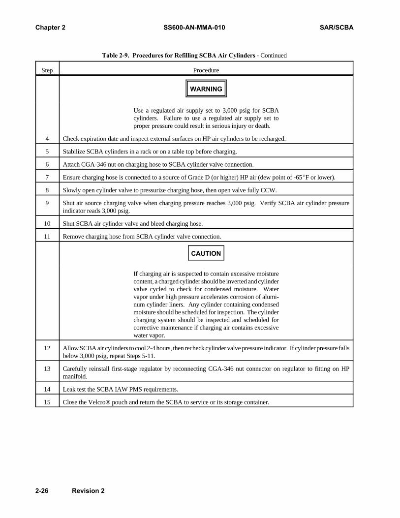
Table 2-9. Procedures for Refilling SCBA Air Cylinders - Continued
Step Procedure
Use a regulated air supply set to 3,000 psig for SCBAcylinders. Failure to use a regulated air supply set toproper pressure could result in serious injury or death.
4 Check expiration date and inspect external surfaces on HP air cylinders to be recharged.
5 Stabilize SCBA cylinders in a rack or on a table top before charging.
6 Attach CGA-346 nut on charging hose to SCBA cylinder valve connection.
7 Ensure charging hose is connected to a source of Grade D (or higher) HP air (dew point of -65EF or lower).
8 Slowly open cylinder valve to pressurize charging hose, then open valve fully CCW.
9 Shut air source charging valve when charging pressure reaches 3,000 psig. Verify SCBA air cylinder pressureindicator reads 3,000 psig.
10 Shut SCBA air cylinder valve and bleed charging hose.
11 Remove charging hose from SCBA cylinder valve connection.
If charging air is suspected to contain excessive moisturecontent, a charged cylinder should be inverted and cylindervalve cycled to check for condensed moisture. Watervapor under high pressure accelerates corrosion of alumi-num cylinder liners. Any cylinder containing condensedmoisture should be scheduled for inspection. The cylindercharging system should be inspected and scheduled forcorrective maintenance if charging air contains excessivewater vapor.
12 Allow SCBA air cylinders to cool 2-4 hours, then recheck cylinder valve pressure indicator. If cylinder pressure fallsbelow 3,000 psig, repeat Steps 5-11.
13 Carefully reinstall first-stage regulator by reconnecting CGA-346 nut connector on regulator to fitting on HPmanifold.
14 Leak test the SCBA IAW PMS requirements.
15 Close the Velcro® pouch and return the SCBA to service or its storage container.

SAR/SCBA SS600-AN-MMA-010 Chapter 2
Revision 2 2-27 / (2-28 Blank)
Table 2-10. Emergency Procedures for the SAR/SCBA
Symptom Effect Corrective Action
Unsteady or diminished air flowthrough hose
Difficulty breathing Straighten air hose, if kinked.
If hose has damaged spot, activate SCBA aircylinder (open cylinder valve) and immedi-ately exit space.
Loss of main air supply Difficulty breathing, dizziness, or dis-tress
Activate SCBA back-up escape air cylinder(open cylinder valve) and immediately exitspace.
Contaminated air enters air supplyor facepiece
Difficulty breathing, dizziness, dis-tress, taste or smell contaminants
Activate SCBA back-up escape air cylinder(open cylinder valve) and immediately exitspace.
SCBA LP alarm (whistle) sounds Loss of SCBA back-up air supplywhile still breathing off main airsupply
Immediately exit work area using main airsupply.

THIS PAGE INTENTIONALLY LEFT BLANK
SAR/SCBA SS600-AN-MMA-010 Chapter 3
Revision 2 3-1
CHAPTER 3FUNCTIONAL DESCRIPTION
3.1 INTRODUCTION.
This chapter defines the functions of the major equipmentgroups for the Supplied Air Respirator (SAR) with the Self-Contained Breathing Apparatus (SCBA). A description ofhow the equipment operates and supporting illustrations arealso included.
3.2 OVERALL FUNCTIONAL DESCRIPTIONS.
The SAR/SCBA is a life-support system that supports Gas-Free Engineer (GFE) operations aboard ships. The majorfunction of the equipment is to allow personnel to safelyenter spaces that may contain hazardous atmospheres. Allof the equipment is portable and can be set up quickly. TheSAR/SCBA is a Type C, pressure-demand system. Thesystem is illustrated in Figure 3-1. Figure 3-2 is a functionalblock diagram of the overall system.
3.2.1 Supplied Air Respirator (SAR). The main compo-nents of the SAR are the Primary Air Supply Pack (PASP)and Reserve Air Supply Pack (RASP). These units serve asthe external air source for the SCBA user(s). Duringoperations, the PASP and RASP are stationed and operatedoutside the potentially hazardous space. PASP/RASPoperators place HP air cylinders on-line and then reduce theair pressure to 60-80 psig. The reduced air travels to theSCBA user(s) from the PASP control panel assembly (CPA)via interconnecting air-supply hoses. As the SCBA user(s)enters the potentially hazardous space, the user remainsconnected to the PASP by use of the interconnecting hoses.Should the airflow from the PASP become inadequate, theuser will activate the SCBA and exit the space.
3.2.2 Self-Contained Breathing Apparatus (SCBA). Themain components of the SCBA are: a full facepiece, tworegulators, air-supply hoses, and two back-up escape aircylinders with a pressure indicator, and an alarm. A full-body harness is worn under the equipment. A speakingdiaphragm inside the facepiece allows SCBA users tocommunicate among themselves inside the work space.Portable air cylinders, used for emergency escape only, canbe activated if the external air source becomes inadequate.Should this occur, the SCBA user will receive up to 15minutes of air and must exit the space. Activating the SCBAis an emergency procedure. When performing the emergencyprocedure, the SCBA user may or may not disconnect the air-supply hose from the PASP. The external air supply may notbe reconnected if disconnected.
3.3 MAJOR FUNCTIONAL DESCRIPTIONS.
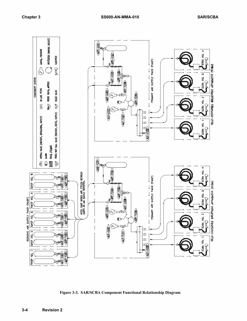
The major functions performed by the PASP, RASP, andSCBA are described in the following paragraphs. A compo-nent functional relationship diagram is provided in Figure 3-3.
3.3.1 Primary Air Supply Pack (PASP). The PASP is alightweight air system with a CPA and one HP air cylinder,both housed within an aluminum case. On top of the CPA,two HP hoses connect the PASP and RASP cylinders to athree-way ball valve.
3.3.1.1 PASP Control Panel Assembly (CPA). ThePASP CPA houses numerous controls and indicators thatactivate and monitor airflow. By turning the three-way ballvalve, the operator selects the cylinder to be on-line. APASP or RASP cylinder is selected by turning the handle inthe appropriate direction. The outlet for the three-way ballvalve is connected to an in-line air filter that traps smallparticles. The filter is located behind the CPA and cannotbe seen on the panel. A regulator is located on the center ofthe panel and reduces the HP air to 60-80 psig (nominal) fordelivery to the air distribution manifold. During an opera-tion, the CPA operator adjusts the regulator to maintain 60-80 psig. An LP gauge monitors the pressure as air travelsthrough the system. The face of the LP gauge displays arange from 0 to 200 psi. An HP gauge displays the airpressure upstream of the regulator. The face of the HPgauge displays a range from 0 to 5,000 psi. Both gauges arethe Bourdon-tube type.
When the supply pressure drops to 500 psig, an LP audiblealarm should sound, and the PASP/RASP operator shouldswitch to a new air cylinder. The alarm is located behind theLP gauge isolation valve and cannot be seen on the panel.Gauge isolation valves are provided for the HP and LPgauges, and allow the operator to isolate the gauges in caseof gauge failure. The distribution manifold area is locatedat the bottom portion of the CPA. Four brass quick discon-nects (QDs) are located on the front of the manifold. SCBAhose(s) connect to the QD(s). A protective dust cap isattached to each QD and covers the opening when the unitis not in service. An LP manifold bleed valve is also locatedin the air distribution manifold area. This bleed valve,which is a spring-loaded valve that snaps shut when not inuse, allows the operator to bleed excess air from the systemafter operations are completed.

Chapter 3 SS600-AN-MMA-010 SAR/SCBA
3-2 Revision 2
Figure 3-1. SAR/SCBA System

SAR/SCBA SS600-AN-MMA-010 Chapter 3
Revision 2 3-3
Figure 3-2. SAR/SCBA Functional Block Diagram
Chapter 3 SS600-AN-MMA-010 SAR/SCBA
3-4 Revision 2
Figure 3-3. SAR/SCBA Component Functional Relationship Diagram

SAR/SCBA SS600-AN-MMA-010 Chapter 3
Revision 2 3-5
Table 3-1. Approximate Air Consumption Rates for PASP/RASP Cylinders
Number ofUsers
Number of Fully Charged Cylinders*
1 2 3 4 5 6
Approximate Air Consumption Rates in Minutes (at 40 liters per minute (lpm)-moderate work rate)
1 55 (34) 105 (65) 165 (103) 219 (136) 274 (171) 329 (205)
2 27 (16) 55 (34) 82 (51) 110 (68) 137 (85) 165 (103)
3 18 (11) 37 (23) 55 (34) 73 (45) 91 (56) 110 (68)
4 14 (8) 27 (16) 41 (25) 55 (34) 69 (43) 82 (51)
*Fully charged to 4,500 psig (3,000 psig) and discharged to 500 psig
3.3.1.2 HP Air Cylinders and Valves (PASP/RASP).The PASP and RASP use the same model HP air cylinder,which is a commercial-off-the-shelf (COTS) item. Eachcylinder holds up to 87 scf of compressed air at a rated ser-vice pressure of 4,500 psig. A full cylinder can supply upto 55 minutes of air, depending on the number of users andrespiration rates. Approximate air consumption ratesaccording to number of users are shown in Table 3-1 above.Each air cylinder contains an aluminum liner and iswrapped with a fiberglass-epoxy composite material. Eachcylinder weighs 18.25 lbs. when unpressurized and must befilled with Grade D air or higher. Each cylinder has anintegral assembly consisting of a handwheel, a cylindervalve pressure indicator, and a rupture disk. The handwheel
opens airflow from the cylinder to the PASP. The airpressure inside the cylinder is monitored by a pressureindicator located on the top portion of the assembly. Theindicator displays air pressure levels from 0 to 4,500 psiin increments of 1,000 psi. If air pressure builds up, theexcess air is released through a rupture disk. Whenconnecting to the PASP, the HP air hoses connect a hand-tight nut (CGA-347) to the outlet on the cylinder valve.
3.3.1.3 HP Hose Assemblies. Each PASP is equippedwith two HP hose assemblies. The HP hose assembly isdisplayed in Figure 3-4. The hoses are made of thermo-plastic and connect the PASP and RASP cylinders to thethree-way ball valve on top of the PASP control panel. The
Figure 3-4. High-Pressure Hose Assembly
Chapter 3 SS600-AN-MMA-010 SAR/SCBA
3-6 Revision 2
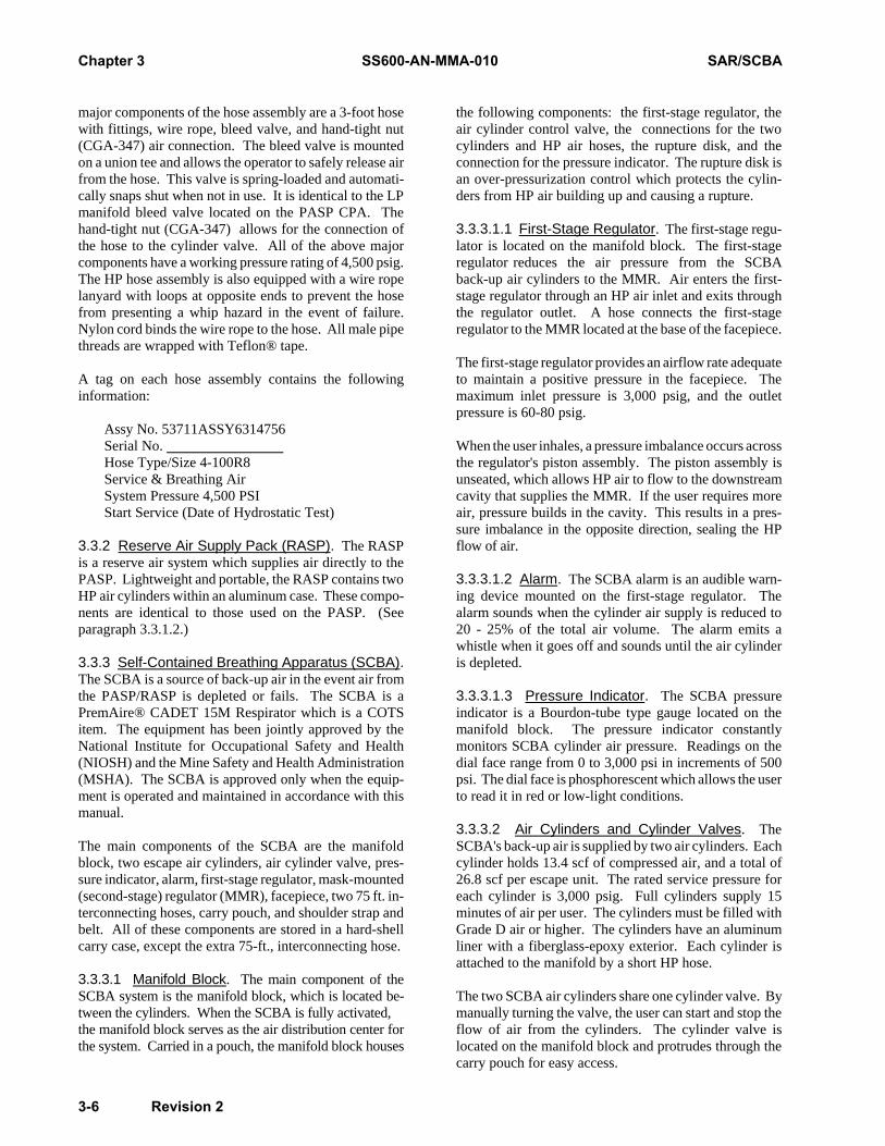
major components of the hose assembly are a 3-foot hosewith fittings, wire rope, bleed valve, and hand-tight nut(CGA-347) air connection. The bleed valve is mountedon a union tee and allows the operator to safely release airfrom the hose. This valve is spring-loaded and automati-cally snaps shut when not in use. It is identical to the LPmanifold bleed valve located on the PASP CPA. Thehand-tight nut (CGA-347) allows for the connection ofthe hose to the cylinder valve. All of the above majorcomponents have a working pressure rating of 4,500 psig.The HP hose assembly is also equipped with a wire ropelanyard with loops at opposite ends to prevent the hosefrom presenting a whip hazard in the event of failure.Nylon cord binds the wire rope to the hose. All male pipethreads are wrapped with Teflon® tape.
A tag on each hose assembly contains the followinginformation:
Assy No. 53711ASSY6314756Serial No. Hose Type/Size 4-100R8Service & Breathing Air System Pressure 4,500 PSIStart Service (Date of Hydrostatic Test)
3.3.2 Reserve Air Supply Pack (RASP). The RASPis a reserve air system which supplies air directly to thePASP. Lightweight and portable, the RASP contains twoHP air cylinders within an aluminum case. These compo-nents are identical to those used on the PASP. (Seeparagraph 3.3.1.2.)
3.3.3 Self-Contained Breathing Apparatus (SCBA).The SCBA is a source of back-up air in the event air fromthe PASP/RASP is depleted or fails. The SCBA is aPremAire® CADET 15M Respirator which is a COTSitem. The equipment has been jointly approved by theNational Institute for Occupational Safety and Health(NIOSH) and the Mine Safety and Health Administration(MSHA). The SCBA is approved only when the equip-ment is operated and maintained in accordance with thismanual.
The main components of the SCBA are the manifoldblock, two escape air cylinders, air cylinder valve, pres-sure indicator, alarm, first-stage regulator, mask-mounted(second-stage) regulator (MMR), facepiece, two 75 ft. in-terconnecting hoses, carry pouch, and shoulder strap andbelt. All of these components are stored in a hard-shellcarry case, except the extra 75-ft., interconnecting hose.
3.3.3.1 Manifold Block. The main component of theSCBA system is the manifold block, which is located be-tween the cylinders. When the SCBA is fully activated,the manifold block serves as the air distribution center forthe system. Carried in a pouch, the manifold block houses
the following components: the first-stage regulator, theair cylinder control valve, the connections for the twocylinders and HP air hoses, the rupture disk, and theconnection for the pressure indicator. The rupture disk isan over-pressurization control which protects the cylin-ders from HP air building up and causing a rupture.
3.3.3.1.1 First-Stage Regulator. The first-stage regu-lator is located on the manifold block. The first-stageregulator reduces the air pressure from the SCBAback-up air cylinders to the MMR. Air enters the first-stage regulator through an HP air inlet and exits throughthe regulator outlet. A hose connects the first-stageregulator to the MMR located at the base of the facepiece.
The first-stage regulator provides an airflow rate adequateto maintain a positive pressure in the facepiece. Themaximum inlet pressure is 3,000 psig, and the outletpressure is 60-80 psig.
When the user inhales, a pressure imbalance occurs acrossthe regulator's piston assembly. The piston assembly isunseated, which allows HP air to flow to the downstreamcavity that supplies the MMR. If the user requires moreair, pressure builds in the cavity. This results in a pres-sure imbalance in the opposite direction, sealing the HPflow of air.
3.3.3.1.2 Alarm. The SCBA alarm is an audible warn-ing device mounted on the first-stage regulator. Thealarm sounds when the cylinder air supply is reduced to20 - 25% of the total air volume. The alarm emits awhistle when it goes off and sounds until the air cylinderis depleted.
3.3.3.1.3 Pressure Indicator. The SCBA pressureindicator is a Bourdon-tube type gauge located on themanifold block. The pressure indicator constantlymonitors SCBA cylinder air pressure. Readings on thedial face range from 0 to 3,000 psi in increments of 500psi. The dial face is phosphorescent which allows the userto read it in red or low-light conditions.
3.3.3.2 Air Cylinders and Cylinder Valves. TheSCBA's back-up air is supplied by two air cylinders. Eachcylinder holds 13.4 scf of compressed air, and a total of26.8 scf per escape unit. The rated service pressure foreach cylinder is 3,000 psig. Full cylinders supply 15minutes of air per user. The cylinders must be filled withGrade D air or higher. The cylinders have an aluminumliner with a fiberglass-epoxy exterior. Each cylinder isattached to the manifold by a short HP hose.
The two SCBA air cylinders share one cylinder valve. Bymanually turning the valve, the user can start and stop theflow of air from the cylinders. The cylinder valve islocated on the manifold block and protrudes through thecarry pouch for easy access.
SAR/SCBA SS600-AN-MMA-010 Chapter 3
Revision 2 3-7
3.3.3.3 Mask-Mounted (Second-Stage) Regulator(MMR). The MMR reduces the air pressure from about70 psig to a breathable level. The regulator maintainsairflow at a maximum rate of 250 lpm. A semiautomaticpush button (don/doff) on the regulator stops the airflowwhen donning and doffing the facepiece. Once thefacepiece is in place, the user inhales to restart the system.As the user inhales, a pilot diaphragm and a power stagediaphragm are activated to respond to the breathingdemands.
When the SCBA is not activated, the user relies upon airsupplied by the PASP/RASP, the external air source. Airtraveling from this external source initially enters theLP manifold of the first-stage pressure regulator, thenflows to the MMR via a short hose.
3.3.3.4 Facepiece. The SCBA is equipped with anUltravue® Facepiece, a full-face mask with five suspen-sion points and adjustable straps. The facepiece has ascratch-proof, polycarbonate lens that provides a widefield of vision. Other features include an inlet checkvalve, an exhalation valve, and a speaking diaphragm forvoice communication.
An exhalation valve in the lower exterior portion of thefacepiece maintains positive pressure. The exhalationvalve is spring-loaded and is shut during normal opera-tions. Whether exhaling or inhaling, a slight positive airpressure is maintained inside the facepiece. The pressureinside the facepiece is above that of the outside atmo-spheric pressure. Maintaining a positive pressure preventscontaminants from entering the facepiece in the event ofan inadequate seal.
3.3.3.5 SCBA Hoses. The SCBA is equipped with fourtypes of hoses: two 75-foot interconnecting air-supplyhoses, an LP air-supply hose, an MMR hose, and two HPair cylinder hoses.
3.3.3.5.1 Interconnecting Air-Supply Hoses. EachSCBA includes two sections of 75-foot interconnectinghoses. The male end of the hose consists of a stainless-steel plug and connects to the PASP QD. The female endof the hose is also a QD and connects to the LP air-supplyhose plug. No more than four sections of interconnectinghose may be linked without voiding the NIOSH/MSHAapproval.
3.3.3.5.2 LP Air-Supply Hose. This hose is 6-incheslong and connects the 75-foot air-supply hose comingfrom the PASP to the first-stage regulator manifold. In anemergency, the LP air-supply hose may be disconnectedfrom the 75-foot air-supply hose. The LP air-supply hoseis equipped with a male plug and a check valve to preventSCBA air from flowing toward the PASP when the SCBAis activated. An external washer near the male plugfacilitates the connection of the two hoses.
3.3.3.5.3 MMR Hose. This hose is 2-feet long andconnects the first-stage regulator to the MMR. At theMMR, the hose is attached to a swivel block.
3.3.3.5.4 HP Air Cylinder Hoses. These two short HPair hoses connect the SCBA air cylinders to the manifold.The hoses are fixed and should remain in place.
3.3.3.6 Carry Pouch, Shoulder Strap, and Belt. TheSCBA carry pouch is worn by the user and contains theSCBA hardware. The pressure indicator, alarm, andcylinder valve protrude through rubber access holes in thepouch.
The carry pouch is constructed of urethane-coated nylonfor durability. The pouch shoulder strap is adjustable andattaches via a snap-in buckle. The adjustable belt isthreaded through two slits at the top of the pouch and canbe removed from the pouch. This configuration allowsthe pouch to slide on the belt for maximum comfort. Tofacilitate donning and doffing, the belt is also equippedwith a snap-in buckle. The belt and strap are 2-incheswide, and the pouch's dimensions are 13 in. × 10.5 in. ×4.6 in.
3.3.3.7 Hard-Shell Carry Case. A hard-shell carrycase is provided with the SCBA. All SCBA components,except one 75-ft. hose, can be stored in the case. Wheninitially provided to the Fleet, the case also contains themanufacturer's operation and maintenance manual, spareparts kit, and filter cartridge.
3.4 SAR/SCBA AIRFLOW PROCESS.
3.4.1 SAR Airflow Process. High-pressure air, GradeD or higher, supplies the SAR/SCBA system. Undernormal operating conditions, PASP/RASP HP air cylin-ders serve as the external source of air for SCBA users.Figure 3-5 illustrates the airflow process. Compressed airflows from the PASP and RASP air cylinders through HPair hoses connected to the PASP CPA. A three-way ballvalve on the PASP CPA allows the operator to select theon-line cylinder. When the three-way ball valve is in theopen position, the airflow process begins. An air filterbelow the three-way ball valve collects particulate matterbefore the air reaches the regulator. The HP and LPgauges monitor airflow pressure to and from the regulator.The LP alarm sounds when the air pressure drops to 500psig. The alarm alerts the PASP/RASP operator to switchto the on-line cylinder.
The regulator reduces the air pressure to approximately60-80 psig. Air travels through the regulator and exits thePASP through QDs on the PASP manifold. The reducedair travels through 75-foot air-supply hose sections toreach the SCBA user in the work space.

Chapter 3 SS600-AN-MMA-010 SAR/SCBA
3-8 Revision 2
3.4.2 SCBA Airflow Process. The PASP/RASP aircylinders supply the external air source to the SCBA.Figure 3-6 illustrates the airflow within the SCBA. TheSCBA is connected to the PASP by hose sections. Eachair-supply hose connects to an LP air-supply hose with acheck valve. From the LP hose, the air flows through thefirst-stage regulator and then air travels to the MMR.The MMR reduces the air pressure from 60-80 psig to abreathable level. Two diaphragms on the MMR sense
and respond to the user's breathing requirements. Exhaledair is expelled through a spring-loaded exhalation valve atthe bottom of the facepiece.
If the external air source is interrupted, depleted, or fails,the SCBA cylinders will be activated as an emergencyprocedure. Once the emergency air reaches the first-stageregulator, it follows the same path as the external air sup-ply. Emergency procedures are outlined in Table 2-10.
Figure 3-5. SAR/SCBA Airflow Diagram

SAR/SCBA SS600-AN-MMA-010 Chapter 3
Revision 2 3-9/(3-10 blank)
Figure 3-6. SCBA Airflow Diagram

THIS PAGE INTENTIONALLY LEFT BLANK
SAR/SCBA SS600-AN-MMA-010 Chapter 4
Revision 2 4-1
WARNING
CHAPTER 4SCHEDULED MAINTENANCE
4.1 INTRODUCTION.
Properly performed scheduled mainte-nance is essential to safe, dependable oper-ation of the Supplied Air Respirator (SAR)with the Self-Contained Breathing Appara-tus (SCBA). Omission or negligent perfor-mance of prescribed maintenance proce-dures could result in equipment failure,injury, or death to personnel.
This chapter provides general information to assist person-nel in reporting problems, and planning and schedulingmaintenance activities for the SAR/SCBA.
4.2 SCOPE.
The scope of this chapter includes general maintenanceinformation and reporting requirements. Maintenanceactivities for the SAR/SCBA are based upon the Navy 3-MPlanned Maintenance System (PMS). This system classifiesmaintenance into two categories: scheduled and unsched-uled.
Scheduled maintenance primarily involves actions requiredto ensure the reliable operation of the SAR/SCBA. Sched-uled maintenance requirements include such actions asinspections, cleaning, leak tests, and operational tests.Scheduled maintenance procedures for the SAR/SCBA areset forth in the Maintenance Index Page (MIP) and Mainte-nance Requirement Cards (MRCs). The initial release MIPand MRCs are effective only until the Semiannual ForceRevisions (SFRs) are issued through regular PMS channels.In the event of conflict between this manual and the PMS,the PMS requirements prevail.
4.2.1 Maintenance Index Pages (MIPs). One MIP,included as part of the PMS, provides an index to all MRCsfor the SAR/SCBA. The MIP contains a cross-reference tothe appropriate MRC for a particular maintenance action.The MIP includes:
! a title that identifies the MRC set! reference publications ! configuration data for the equipment! SYSCOM maintenance requirement card control
number and periodicity code! all maintenance requirements for a given system,
subsystem, or equipment! a designator to indicate the MRCs that include one
or more tests! recommended rates, estimated hours, and a
periodicity code for related maintenance
The alphanumeric periodicity code, as it appears on the MIPfor each maintenance action, is also included on the MRC.This code identifies the frequency of each maintenanceaction.
4.2.2 Maintenance Requirement Cards (MRCs).SAR/SCBA scheduled maintenance is accomplished on ascheduled and periodic basis, or on a situation-dictatedbasis. Maintenance procedures are provided on MRCs.Each MRC includes:
! a brief description of the task! a periodicity code! recommended rates, estimated hours, and a
periodicity code for related maintenance! required safety precautions! required tools, parts, and test materials! detailed procedures
The frequency of individual PMS maintenance actions isdescribed by the periodicity codes shown in Table 4-1. Forexample, M-1R indicates that the action be performed on aquarterly basis or whenever a specific situation occurs, suchas after an operational use.
Unscheduled maintenance includes actions required tolocate equipment faults and correct failures or performancedegradations. Unscheduled maintenance, such as repair andcertain replacement procedures, is normally performed bymaintenance technicians trained in service requirements.Unscheduled maintenance actions are identified in Chapter5, Troubleshooting and in Chapter 6, Corrective Mainte-nance.

Chapter 4 SS600-AN-MMA-010 SAR/SCBA
4-2 Revision 2
WARNING
Table 4-1. Periodicity Codes
Code Periodicity
Calendar
DWMQSA
18M24M
DailyWeeklyMonthlyQuarterlySemiannuallyAnnuallyEach 18 monthsEach 24 months
Non-Calendar
RU
Situation requirementUnscheduledmaintenance
Inactive Equipment Maintenance
LUPMSUOT
Lay-up maintenancePeriodic maintenanceStart-up maintenanceOperational test
4.3 U. S. NAVY 3-M SYSTEM COVERAGE ANDPROBLEM REPORTING.
The provisions of the U. S. Navy 3-M Manual(OPNAVINST 4790.4B) apply to the SAR/SCBA. Accord-ingly, problems and corrective maintenance arising fromPMS should be properly reported using OPNAV Form4790/2K to ensure timely and accurate Maintenance DataSystem (MDS) documentation of SAR/SCBA performancein the Fleet. In addition to Fleet requirements, SAR/SCBAMDS input from Fleet units is used by the In-ServiceEngineering Agent (ISEA) to identify and correct problemswith the system, documentation, and provisioning, includingCoordinated Shipboard Allowance List support.
The ISEA for the SAR/SCBA may be contacted as follows:
Mail: Commanding OfficerCoastal Systems Station, Code A53Panama City, FL 32407-7001
Telephone: 850-234-4653 (Commercial)436-4653 (Defense Switch Network)
Fax: 850-234-4775 (Commercial)436-4775 (Defense Switch Network)
Naval Message Plain Language Address Directory (PLAD):NAVSURFWARCEN COASTSYSTA PANAMA CITY FL(2530)
Units and activities are requested to make the SAR/SCBAISEA an ACTION or INFO addressee, as appropriate, onmessages pertaining to this equipment, particularly CasualtyReports (CASREPs), Operational Reports (OPREPs), SafetyReports, and message work requests that may require ISEAaction.
Discrepancies or problems with this technical manual,should be reported immediately on the NAVSEA/SPAWARTechnical Manual Deficiency/ Evaluation Report (TMDER),NAVSEA 4160/1 (REV 3/2001). The form is located in theback of this manual.
The form should be submitted to:
CommanderNAVSURFWARCENDIVCode 5B31, Bldg. 13884363 Missile WayPort Hueneme, CA 93043-4307
Additionally, OPNAVINST 4790.4B (3-M Manual) requiresthat a PMS feedback report (PMS FBR), OPNAV 4790/7BForm, be submitted for any PMS-related documentation ortechnical problem.
4.4 GENERAL MAINTENANCE INSTRUCTIONS.
Repair or replace worn or damaged partswith authorized replacement parts. Fail-ure of SAR/SCBA during operationsmay result in injury or death to operators.
Do not disassemble components whileSAR/SCBA is pressurized. Before per-forming maintenance, ensure that airsupply has been shut down and all pres-sure has been vented (bled) from thesystem. Accidental exposure to escapingHP air may result in damage to equip-ment, serious injury, or death to person-nel.
4.4.1 Disassembly and Replacement Parts. Disassem-ble the equipment only as necessary for scheduled mainte-nance, cleaning, inspection, and repair. Maintenance