Santa Clara University human powered vehicle 2013-2014
204
Santa Clara University Scholar Commons Mechanical Engineering Senior eses Engineering Senior eses 6-11-2014 Santa Clara University human powered vehicle 2013-2014 Peter Chester Santa Clara University Luis Flores Santa Clara University Ian Jones Santa Clara University Ryan Nakamura Santa Clara University Dylan Porter Santa Clara University See next page for additional authors Follow this and additional works at: hps://scholarcommons.scu.edu/mech_senior Part of the Mechanical Engineering Commons is esis is brought to you for free and open access by the Engineering Senior eses at Scholar Commons. It has been accepted for inclusion in Mechanical Engineering Senior eses by an authorized administrator of Scholar Commons. For more information, please contact [email protected]. Recommended Citation Chester, Peter; Flores, Luis; Jones, Ian; Nakamura, Ryan; Porter, Dylan; and Stephens, Peter, "Santa Clara University human powered vehicle 2013-2014" (2014). Mechanical Engineering Senior eses. 22. hps://scholarcommons.scu.edu/mech_senior/22
Transcript of Santa Clara University human powered vehicle 2013-2014

Santa Clara UniversityScholar Commons
Mechanical Engineering Senior Theses Engineering Senior Theses
6-11-2014
Santa Clara University human powered vehicle2013-2014Peter ChesterSanta Clara University
Luis FloresSanta Clara University
Ian JonesSanta Clara University
Ryan NakamuraSanta Clara University
Dylan PorterSanta Clara University
See next page for additional authors
Follow this and additional works at: https://scholarcommons.scu.edu/mech_senior
Part of the Mechanical Engineering Commons
This Thesis is brought to you for free and open access by the Engineering Senior Theses at Scholar Commons. It has been accepted for inclusion inMechanical Engineering Senior Theses by an authorized administrator of Scholar Commons. For more information, please contact [email protected].
Recommended CitationChester, Peter; Flores, Luis; Jones, Ian; Nakamura, Ryan; Porter, Dylan; and Stephens, Peter, "Santa Clara University human poweredvehicle 2013-2014" (2014). Mechanical Engineering Senior Theses. 22.https://scholarcommons.scu.edu/mech_senior/22

AuthorPeter Chester, Luis Flores, Ian Jones, Ryan Nakamura, Dylan Porter, and Peter Stephens
This thesis is available at Scholar Commons: https://scholarcommons.scu.edu/mech_senior/22


Santa Clara University Human Powered Vehicle 2013-2014
by
Dylan Porter, Peter Chester, Peter Stephens, Luis Flores, Ian Jones, and Ryan Nakamura
SENIOR DESIGN PROJECT REPORT
Submitted in partial fulfillment of the requirements for the degree of
Bachelor of Science in Mechanical Engineering School of Engineering Santa Clara University
Santa Clara, California June 11, 2014

iii
Santa Clara Human Powered Vehicle 2013-2014 Dylan Porter, Peter Chester, Peter Stephens, Luis Flores, Ian Jones, and Ryan Nakamura
Department of Mechanical Engineering Santa Clara University
2014
ABSTRACT
This document discusses the conceptual design for the 2013-2014 Santa Clara University
Human Powered Vehicle. The objective of the Santa Clara University Human Powered Vehicle
team is to design and manufacture a human powered vehicle that is practical, sustainable, and
efficient. Key design features include a partial body fairing, tilt and ackermann steering, and
cargo space. Ultimately we had to block out the tilt steering because its operation conflicted with
the Ackermann steering. This vehicle’s design satisfies the primary needs of a commuter and
ultimately serves as a practical alternative to an automobile. Finally, this design complies with
the requirements set by the American Society of Mechanical Engineers for the 2014 Human
Powered Vehicle Challenge West Competition.

iv
Acknowledgements
The Santa Clara University Human-Powered Vehicle Team would like to extend their
sincere appreciation to Santa Clara University and the Santa Clara University School of
Engineering for their educational guidance and financial support. The team would also like to
acknowledge Dr. Drazen Fabris and Dr. Calvin Tzeng, two of the project advisors, for their
guidance and advice during the design and testing stages of the project. Additionally, our team
would like to thank Dr. Robert Marks, our inspirational professor, Mr. Don MacCubbin, our
shop instructor, and Wesley Rooney, an ASME Human Powered Vehicle Challenge Judge, for
assisting us in addressing and implementing customer needs into our design as well as helping us
understand all of the rules for the HPV competition. We would also like Chavez welding for
their generosity in helping our team greatly in the manufacturing process of our vehicle. Lastly,
our team would like to express the utmost gratitude to our family and friends who have
supported us these last four years at Santa Clara University; without their hard work and
dedication, this endeavor could never be realized.

v
TABLE OF CONTENTS Page
Signature Page ………………………………...……………………………………….....….. i Title Page ………………………………………………………...…………………………... ii Abstract ………………...…………………………………………………………...………... iii Acknowledgments ………………….………………………………………………...…......... iv Variable Definitions…………………………………………………………………………...
x
Chapter 1 Introduction…………………...……………………………….……................ 1 1.1 Background and Motivation.…….…………………………………………….. 1 1.2 Brief Literature Overview……….………………………………………......... 2 1.3 Problem Statement……..…..…………………………………………….…..... 5 1.4 ASME HPV Requirements…..….…………………………………………...... 6
Chapter 2 System Level Considerations……....………………………………................ 9 2.1 System Level Overview…..………………….……...……………….............. 9 2.2 Customer Definitions and Needs..………………………………………......... 10 2.3 Primary Needs……………………………….......……………………………. 11 2.4 Customer Survey………………………………………………….................. 12 2.5 System Requirements……………………………………………………........ 13 2.6 System Level Requirements………………………………………………...... 14 2.6.1 Functional Analysis……………………………………………………………. 14 2.6.2 Considered Design Ideas……..………………………..………………………. 16 2.6.3 Team and Project Management………………………..………………………. 18 2.7 Engineering Standards and Realistic Constraints……………………………... 19 2.7.1 Economic……………………………………………………………............... 19 2.7.2 Sustainability………………………………………………………………...... 20 2.7.3 Manufacturability………………………………………………………........... 23 2.7.4 Ethical………………………………………………………………................. 24 2.7.5 Health and Safety……………………………………………………................ 30 2.7.6 Social...................………………………………………………………........... 31 2.7.7 Aesthetics............…………………………………………………………….... 32
Chapter 3 Detailed Design……………………………………...……………………….... 33 3.1 Frame ………………………………………………………………...……....... 33 3.1.1 Frame Background…………………………………........................................ 33 3.1.2 Frame Design……………………………........……........................................ 34 3.1.3 Frame Analysis…………………….......……………........................................ 36 3.1.4 Frame Mechanical Description......…………………........................................ 47 3.1.5 Frame Test and Verification Data..…………………........................................ 49 3.2 Steering ……………………………………………………………...……....... 51 3.2.1 Steering Background…......…………………………........................................ 51 3.2.2 Steering Design…………………………........…….......................................... 51 3.2.3 Steering Analysis………………….......……………........................................ 59 3.2.4 Steering Mechanical Description......………………........................................ 61 3.2.5 Steering Test and Verification Data..…………………...................................... 62 3.3 Aerodynamics......…………..………………………………………...……....... 64 3.3.1 Aerodynamics Background....………………………........................................ 64

vi
3.3.2 Aerodynamics Design.....….……………........…….......................................... 64 3.3.3 Aerodynamics Analysis………………….......……………............................... 65 3.3.4 Aerodynamics Mechanical Description......………........................................... 67 3.4 Drive Train..........…………..………………………………………...……....... 69 3.4.1 Drive Train Background.........………………………........................................ 69 3.4.2 Drive Train Design.....….…………....…........…….......................................... 69 3.4.3 Drive Train Analysis………………...…........……………............................... 72 3.4.4 Drive Train Mechanical Description..........………............................................ 73 3.4.5 Drive Train Test and Verification Data..…………............................................ 74
Chapter 4 System Integration.....………………..……………...………………………..... 75 4.1 System Integration and Test........………........................................................... 75 4.2 Axel Tab Redesign...........................................................…………………...... 76 4.3 Experimental Protocol and Results…………………........................................ 78 4.4 Race Results......................................................................…………………..... 79
Chapter 5 Cost Analysis...................................................................................................... 80 Chapter 6 Business Plan............………………..……………...………………………..... 81 Chapter 7 Summary and Conclusion.....………..……………...………………………..... 89
Bibliography............................................................................................................................... 98 Appendices................................................................................................................................. 100
Appendix A [Detailed Calculations].............................................................................. 100 Appendix B [Detail And Assembly Drawings].............................................................. 110 Appendix C [Initial Design Aids and Background Material]......................................... 151 Appendix D [Project Management Data]....................................................................... 160 Appendix E [Experimental Data]................................................................................... 163 Appendix F [ASME Competition Results].................................................................... 165 Appendix G [Senior Design Conference Presentation Slides and Summary]................ 166 Appendix H [Relevant Patents]...................................................................................... 180 Appendix I [Customer Research]………..…………………………………................ 181

vii
List of Tables and Figures Figures
Page [Figure 1] Final Design Model................................……………………………….………….. 2 [Figure 2] ASME HPVC Roll Cage Requirements.....……………………………….………. 7 [Figure 3] System Overview...................................……………………………….………….. 9 [Figure 4] Vehicle Model Without Fairing and Storage..…………………………….………. 10 [Figure 5] Functional Decomposition.....................……………………………….………….. 15 [Figure 6] Input-Output Vehicle Diagram……….......……………………………….………. 16 [Figure 7] Project Timeline.....................................……………………………….………….. 19 [Figure 8] Initial Wheel Axle and Ackermann Design..…………………………….………... 23 [Figure 9] Final Wheel Axle and Ackermann Design................................…………………... 24 [Figure 10] Main Vehicle Frame CAD Model…….....……………………………….………. 34 [Figure 11] Simplified Representation of Vehicle Used to Determine Tipping Point………... 36 [Figure 12] Simplified Representation of Vehicle Under Braking Deceleration……………... 38 [Figure 13] Free Body Diagram of Frame.....................……………………………………… 41 [Figure 14] Diagram of Critical Points in the Frame..……………………………….….……. 42 [Figure 15] FEA Results For 1200 lb Top Load and 600 lb Side Loads...............…………… 43 [Figure 16] FEA Results For 600 lb Rider Applying a Force of 300 lb to the Drivetrain……. 45 [Figure 17] Design Changes Made After FEA.....................…………………….………..….. 46 [Figure 18] Reduction in stresses in the RPS due to Design Changes.......…………………… 47 [Figure 19] Finished Frame...................................…………………………….….…………... 48 [Figure 20] Frame Load Testing Setup..…………………………..………………….………. 49 [Figure 21] Angle Iron Front Boom Reinforcement.....................………………...………….. 50 [Figure 22] Turn Radius of Ackermann Steering ……….......……………………….………. 53 [Figure 23] Ackermann Steering Control Arms, the Connecting Rod and the Ball Joint......... 54 [Figure 24] Diagram of Kingpin and Wheel Axles Placement.…………………………….… 55 [Figure 25] Vertical Versus Angled Kingpin Angles.................................…………………... 56 [Figure 26] Tilt Steering design with Gas Springs and Parallelogram Geometry.……............ 57 [Figure 27] Definition of Camber…………………………………………………...………... 58 [Figure 28] FEA Results for 600 lb Load on the Tilt Steering.……………............................. 60 [Figure 29] Ackermann Steering and Kingpin Axle Mechanisms....................………………. 61 [Figure 30] The Steering with the Tilt Blocked Out...……………………………….….……. 62 [Figure 31] Fairing Design Illustrations...............…………………………………………….. 64 [Figure 32] Iteration in CFD of drag of the maximum width Rectangular Fairing…………... 66 [Figure 33] Iteration in CFD of drag of the Teardrop shaped Fairing..............................……. 67 [Figure 34] The Fairing Used for the Competition...……………………………….………… 68 [Figure 35] Chain Tensioner Setup Used for the Competition...........................……………... 70 [Figure 36] The Front Gear Used in the Vehicle.…………………………….………………. 70 [Figure 37] Teflon Chain Guide Used to Protect the Chain.....................……………………. 71 [Figure 38] Chain Idler Used on the Bottom of Trike ……….......…………..……....………. 72 [Figure 39] Redesign of the Drivetrain.....................................………………………………. 74 [Figure 40] PVC Prototype used to Illustrate the Steering and Frame Geometry..…………... 76 [Figure 41] Failure of Axle Tab................................……..…………………………………... 76

viii
[Figure 42] Axle Tab Designs FEA…….....……………………………….…….…………… 77 [Figure 43] Logo that will be used for our Bicycle Company………………………………... 83 [Figure 44] Number of Units Produced………………………………………..……………... 86 [Figure 45] Developmental Costs.....................………………………………………………. 87 [Figure 46] Financial Model Used to Find the Return on Investment..………………………. 88 [Figure A.1] Ackermann Calculations………...…..……………………………….….……… 100 [Figure A.2] Braking Weight Transfer Calculation……………………………….….…….… 101 [Figure A.3] Tipping Point Calculations…...……..……………………………….….…….… 102 [Figure A.4] Free Body Diagram of Frame..……..……………………………….….…….… 103 [Figure A.5] Calculations for the Stresses at the Welds A and B.……………….….…….…. 104 [Figure A.6] Calculations for the Stresses at the Weld C..……………………….….…….…. 105 [Figure A.7] Calculations for the Stresses at the Crux of the Main Tube..……….….…….…. 106 [Figure A.8] Calculations for the Forces on the Drivetrain...…………………….….…….…. 107 [Figure A.9] Data Points Entered into Abaqus………..………………………….….…….…. 108 [Figure C.1] Build Plan for the Vehicle……………….………………………….….…….…. 156 [Figure C.2] Sketch of Main Vehicle Frame…………..………………………….….…….…. 157 [Figure C.3] Concept Sketch of Vehicle………………………………………….….…….…. 158 [Figure C.4] Concept Sketch After Customer Feedback...……………………….….…….…. 158 [Figure C.5] Initial System Level Sketch ….…………………………………….….…….…. 159 [Figure H.1] Patent Tilt Steering……………………………………………………………… 180 Tables [Table 1] Material Property Tradeoff…………………………………………………………. 35 [Table 2] Final Design Measurements ………………...……………………………………... 37 [Table 3] Properties of Aluminum…………………………......……………………………... 40 [Table 4] FEA modeling Methods for Frame..……………………………………………….. 42 [Table 5] FEA Frame Results………………………………………………………………… 43 [Table 6] Modeling Method for Force of a Rider…..………………………………………… 44 [Table 7] The von Mises and Max Principal Stresses for the Frame due to a Rider…………. 45 [Table 8] The von Mises and Max Principal Stresses for the Tilt Steering….….………….… 60 [Table 9] Fairing Dimensions……………………………………………………...….……… 65 [Table 10] Experimental Results….………………………………………………………….. 78 [Table 11] Tabulated Ranking of the SCU HPV 2014 during the HPVC West 2014….……. 79 [Table 12] Extended production expense for our first year of building for Business Plan…… 84 [Table 13] Future Production Cost Summary for Business Plan.…………………………….. 84 [Table 14] Total parts cost for our vehicle for Business Plan.………………………………... 85 [Table 15] Market Data used in Financial Model………………………………….….……… 86 [Table A.1] Drivetrain Gearing Calculations…...………………………………….….……… 109 [Table C.1] Product Design Specifications…......………………………………….….……… 151 [Table C.2] Quality Function Development........………………………………….….……… 152 [Table C.3] HPV Alternatives and Evaluation.....………………………………….….……… 153 [Table C.4] Initial Goals and Benchmarks.…......………………………………….….………
154

ix
[Table D.1] Gantt Chart Deadlines……....…......………………………………….….……… 160 [Table D.2] Preliminary Estimated Expenses......………………………………….….……… 161 [Table D.3] Budget and Funding………….........………………………………….….……… 162 [Table E.1] Turning Radius Calculations…........………………………………….….……… 163 [Table E.2] Top Speed Testing……………........………………………………….….……… 164 [Table F.1] 2014 ASME HPV West Results.......………………………………….….……… 165

x
Variable Definitions:
ab Braking deceleration
ay Centripetal acceleration
CF Cornering stiffness of front wheels
CR Cornering stiffness of rear wheel
Fb Braking force
F Force
Fc Force due to centripetal acceleration
FT Force at which the vehicle tips over
g Acceleration due to gravity
HG Height of center of gravity
LG Distance of center of gravity from front wheels
m Mass
R Radius of turn
T Torque
TR Wheel track (distance between front wheels)
V,v Velocity
W Weight
WB Wheelbase (distance between front and rear wheel axles)
WF, FF Reaction force on front wheels
WR, FR Reaction force on rear wheel
δ Angle that the vehicle needs to turn at to make a given radius of turn
θ Angle
μc Coefficient of friction

1
1 Introduction
1.1 Background and Motivation
The Santa Clara University Human Powered Vehicle (HPV) team is composed of six
senior mechanical engineering students with a desire to build a vehicle that will be a practical
alternative to a motorized vehicle. Currently, gas powered vehicles are the main form of
transportation for Americans; this dependence on vehicles has a negative impact on our global
environment due to the large-scale consumption of fossil fuels and greenhouse gas emissions. In
recent years, the rise in demand for renewable energy power sources has increased tremendously
even as the demand for gasoline continues to grow. HPVs, such as bicycles, are some of the
purest forms of sustainable transportation. Our goal was to design and fabricate a well-
engineered human powered vehicle that would be an aesthetically attractive, practical,
sustainable, and efficient alternative to the modern commuter car. Our design is a tadpole-style
recumbent tricycle with rear-wheel drive and a partial fairing for a single rider. The SCU team
has placed priority on the implementation of a protective roll cage system as well as stable
steering, an efficient drivetrain system and an aerodynamic fairing. Emphasis was also placed on
manufacturing a tricycle that is stable, easy-to-ride, and most importantly safe. The unique
innovation pertaining to our design was the use of both tilt and Ackermann steering. However,
after the vehicle was assembled and testing was conducted, we noticed that the design in its
current state would not function correctly. It was decided to block out the tilt-steering portion of
our vehicle for the American Society of Mechanical Engineers (ASME) West Coast
Competition. The reasoning behind this is explained in more detail in the steering section of this
report. The tricycle was constructed from Aluminum 6061 T6 for its desirable properties such as
lightweight, high-strength, and resistance to corrosion. This vehicle’s design satisfies the primary
needs of a commuter traveling approximately 20 miles round-trip, ultimately serving as a
practical alternative to an automobile. Finally, this design complies with the requirements set
forth by the ASME members for the 2014 Human Powered Vehicle Challenge West
Competition. A rendering of the final vehicle prototype, nicknamed Pegasus, can be seen below
in Figure 1:

2
Figure 1: The final design model used to construct the vehicle.
1.2 Brief Literature Overview
Cerberus: A human powered vehicle
Document Abstract:
“A recumbent trike was designed and built for the ASME Human Powered Vehicle Challenge
held at San Jose State University in April of 2013. The vehicle was designed to be low cost for
use by commuters and as primary transportation in developing countries. The vehicle placed 11th
overall in the competition out of 29 teams, and scored 8th in the innovation event, which was its
best ranking out of the 5 individual events.”
The Cerberus document is the thesis written for the human powered vehicle project at
SCU in 2013.This document covers the design process and specifications of the Cerberus model
HPV entered in last year’s ASME HPV competition. This document has been referenced for

3
benchmark values and a comparison of current design ideas to implemented ones for the
Cerberus. This includes the consideration of what design ideas were successful and implemented
into the design, as well as which design ideas were unsuccessful or disregarded. References to
the competition have been noted as well. Indications as to how the vehicle performed in the
competition provided motivation for design parameters to succeed in the categories of the ASME
competition.
Vehicle Aerodynamics
Text Preface:
“This volume is primarily an assemblage of published papers selected to illustrate current
activity in the field of vehicle aerodynamics. In its broadest sense, vehicle aerodynamics
encompasses many different and interesting aspects of the airflow around and through a vehicle.
Many of these aspects are addressed, including wind tunnel testing, on-road testing,
computational simulations, and selected examples of aerodynamic development in a vehicle’s
design and development process. This collection of papers does not purport to represent either a
comprehensive coverage or a critical assessment of road-vehicle aerodynamic technology. It is
limited by what is available and there are consequent gaps in the technical coverage.
Furthermore, in the highly competitive and commercial auto industry, where proprietary
considerations are important, current publications may not represent state-of-the-art technology.”
As stated above, the vehicle aerodynamics text is an assembly of published papers on the
behavior of airflow over vehicles in testing. Each section of the text discussed the variation of
testing for aerodynamic analysis and the results and observations of each test. These observations
were made on air flow behavior, factors of vehicle design contributing to drag, and more. This
text was referenced for design considerations in the fairing selection of the vehicle. In addition,
the analyses made in the published papers provided insight to successful body stylings of the
vehicle.
Human Powered Vehicles
Text Preface:
“This book reviews the history of human-powered water, land, and air vehicles and concentrates
on the significant developments that have led to spectacular improvements in performance
4
during the past two decades. This is the first comprehensive and up-to-date scientific and
practical overview of all types of human-powered vehicles.”
This book provided valuable insight on innovative mechanisms we wanted to incorporate
in our vehicle. The sections that addressed drive-train design, steering design, and suspension
design were of particular relevance to the scope of the project. Specific engineering analysis was
done in these sections and has been incorporated in our vehicle design. Various figures were
included in the sections to visually depict the engineering principles that were helpful during the
research and design phase. Specific crank rotation angles were discussed and included for the
drive-train design of the vehicle.
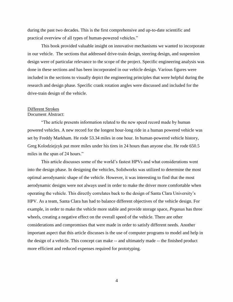
Different Strokes
Document Abstract:
“The article presents information related to the new speed record made by human
powered vehicles. A new record for the longest hour-long ride in a human powered vehicle was
set by Freddy Markham. He rode 53.34 miles in one hour. In human-powered vehicle history,
Greg Kolodziejzyk put more miles under his tires in 24 hours than anyone else. He rode 650.5
miles in the span of 24 hours.”
This article discusses some of the world’s fastest HPVs and what considerations went
into the design phase. In designing the vehicles, Solidworks was utilized to determine the most
optimal aerodynamic shape of the vehicle. However, it was interesting to find that the most
aerodynamic designs were not always used in order to make the driver more comfortable when
operating the vehicle. This directly correlates back to the design of Santa Clara University’s
HPV. As a team, Santa Clara has had to balance different objectives of the vehicle design. For
example, in order to make the vehicle more stable and provide storage space, Pegasus has three
wheels, creating a negative effect on the overall speed of the vehicle. There are other
considerations and compromises that were made in order to satisfy different needs. Another
important aspect that this article discusses is the use of computer programs to model and help in
the design of a vehicle. This concept can make -- and ultimately made -- the finished product
more efficient and reduced expenses required for prototyping.

5
Human-Powered Vehicles-Aerodynamics of Cycling
This article was written by an applied physics professor at Universidad de Salamanca in
Spain. The article analyzed the different types of human powered vehicles spanning from aerial
to water to land. More specifically, the article focuses on the aerodynamics and fluid mechanics
of cycling in the wind. The article demonstrated well thought-out, in-depth calculations of
different aerodynamic drag forces and the effects of wind on cycling speeds. This article was
mainly referenced to analyze data that has already been calculated and to determine the different
aerodynamic effects of wind on bicycles. One sentence that stood out was the following: “The
effect of the position and geometry of the rider (prone or supine) and bicycle is extraordinary,
but the use of high technology full fairings in recumbent bicycles is astonishing.” Due to the fact
that our vehicle has a recumbent design and included a partial, frontal fairing, the recorded data
in this article proved to be extremely advantageous to the scope of the project.
1.3 Problem Statement
As the consumption of fossil fuels and greenhouse gases continue to escalate, the
motivation to develop sustainable, alternative forms of transportation have steadily increased.
According to Commuting Statistics, if 5% of the United States population utilized a HPV,
roughly 3 billion gallons of gasoline would be conserved each year. In addition, most motorized
vehicles have high expenses including the initial purchasing price, cost of fuel, and routine
vehicle maintenance. Currently, there are four primary alternatives for petroleum-powered
vehicles: electric powered vehicles, walking, regional transit, and human-powered vehicles.
Although these alternatives protect the environment, most of these alternatives have significant
issues that make them less viable than petroleum vehicles. For the human-powered vehicle,
several key problems that are commonly encountered include: low speed, portability, minimal
storage space, personal exhaustion, and minimal safety features. We hope that our work will help
to further the ability of human powered vehicles to address these concerns.

6
1.4 ASME HPVC Requirements
In order to gauge our vehicle’s performance, we participated in the 2014 ASME West
Coast Human Powered Vehicle Challenge. The challenge took place from April 25, 2014
through April 27, 2014 and was split up into four specific sections:
The Design Event
Design report detailing design, analysis, and testing submitted in advance of the
competition
Design presentation and safety and static presentation
The Speed Event
Time trials were conducted at the Santa Clara velodrome
A one lap run
The Innovation Event
A presentation to the ASME judges that showcased our unique innovation incorporated
into the design of the vehicle
The Endurance Event
A two and a half-hour race with various obstacles in which we completed as many 1.3km
laps as possible
Mandatory Safety Requirements
All quoted text in this section comes directly from the Rules for the 2014 Human Powered
Vehicle Challenge (https://community.asme.org/hpvc/m/default.aspx).
General
o “The safety of participants, spectators, and the general public will override all
other considerations during the competition.”
Performance Safety Requirements
o Vehicle “can come to a stop from a speed of 25 km/hr in a distance of 6.0 m.”
o Vehicle “can turn within an 8.0 m radius.”
o Vehicle “can demonstrate stability by traveling for 30 m in a straight line at a
speed of 5 to 8 km/hr”

7
Rollover Protection System
Figure 2 : ASME HPVC roll cage requirements for competing vehicles
o “Top Load: A load of 2670 N per driver/stoker shall be applied to the top of the
roll bar(s), directed downward and aft (towards the rear of the vehicle) at an angle
of 12° from the vertical, and the reactant force must be applied to the roll bar
attachment point and not the bottom of the roll bar (unless the bottom is the
attachment point). Note that there may be one roll bar for the driver and another
roll bar for the stoker which will result in each RPS having an applied load of
2670 N, or the driver and stoker can both be protected by a single roll bar which
will result in the RPS having an applied load of 5340 N.”
o “Side Load: A load of 1330 N per driver/stoker shall be applied horizontally to
the side of the roll bar at shoulder height, and the reactant force must be applied to
the roll bar attachment point and not the other side of the roll bar. Note that there
may be one roll bar for the driver and another roll bar for the stoker which will
result in each RPS having an applied load of 1330 N, or the driver and stoker can

8
both be protected by a single roll bar which will result in the RPS having an
applied load of 2670 N.”
Some important dates include the following
Entry/Registration Deadline: March 2, 2014
Design Reports Due: March 24, 2014
Report Update Due: April 25, 2014
On-Site Registration: April 25, 2014
The motivating factor behind the Human Powered Vehicle project yields a multitude of
valuable aspects which pertain to many organizations and goals. The primary objective, as stated
earlier, is to design and manufacture a commuter vehicle that would compete with the car as an
alternative form of transportation. We will also be competing and representing the University at
a National American Society of Mechanical Engineers competition.
The importance of this project is to create a better environment for those who want to use
human powered transportation. The project is aimed towards using alternative methods of
transportation instead of relying on transportation powered by our natural resources. In addition
to improving the environment we live in it will improve health, reduce hydrocarbon pollution
and of course will be less expensive.

9
2 Systems Level Considerations
2.1 System Level Overview
Our team built a vehicle that aims to replace the commuter car; all of the features
included in the vehicle were designed with that idea in mind. Some of these features are
represented in Figure 1. In order to be a viable commuter vehicle the HPV had to make use of
current infrastructure, protect the rider and have space for storage among a variety of other
considerations.
In order to work more efficiently and create a better overall vehicle, it was broken down
into several different subsystems, including: Fairing, Frame, Seating, Steering and
Drivetrain. Figure 3 shows the vehicle and its subsystems.
Figure 3: This is a system overview of the SCU HPV design.

10
Figure 4: The vehicle without the fairing and storage included.
2.2 Customer Definitions and Needs
Design Criteria/PDS
In conjunction with the brainstorming and research and development phases, the team
evaluated various designs that would result in a competitive vehicle. The finalized product
design specifications are available in Appendix C. Many of the specifications established by the
team pertained to the ASME regulations and are denoted by the “Competition” category in the
ASME HPVC requirements. The measurements (top speed, etc.) that our prototype achieved are
also included.
In order to prioritize and establish a correlation between customer and functional
requirements, the team constructed a House of Quality (HoQ) for our human powered vehicle
“The Pegasus” (Lowe). Our design was benchmarked against SCU’s entry from last year
(Cerberus) and the production Catrike 700. The HoQ is located in Appendix C. With the help of
the HoQ, different design alternatives were evaluated for the potential benefits and drawbacks of
each design option based on engineering knowledge, customer feedback, and common sense and
ultimately settled on our current design

11
City/Communities
The primary customers were commuters traveling short distances in urban areas where
bike lanes are available. These primary customers are part of the 51% of the population that
travels 20 miles or less each day as part of their commute (Statistician Brain). Our concept
addressed the needs of an environmentally conscious society, including current automobile
drivers as well as cyclists who might be intrigued by the potential of greater speed and storage
capability.
ASME Judges
Our primary design goal was to meet the needs of the customer. However, we also
designed our vehicle to meet the requirements of the ASME competition judges and the specific
challenges of the competition.
SCU Judges/ Advisors
Our next group of potential customers was the Santa Clara University judges’ panel at the
senior design presentations. This audience was more extensive in the sense that we competed
against different senior design projects rather than different designs of the same project. Thus,
we set out to convince the panel that our idea had future market potential and was well
engineered. The judges who participated in the senior design presentations are experts in the
manufacturing and fabrication fields, so we considered the viability of our design as if it were to
enter the vehicular market.
2.3 Primary Needs
The primary customer for Pegasus is a commuter who averages 20 miles roundtrip or less
on a daily basis. We wanted to design and manufacture our vehicle to be fast enough to be an
appealing alternative to a car, at an economic and reasonable price. Moreover, our final design
was sufficiently light and easy to transport.
From an ethical and safety standpoint, one essential requirement set forth by the team
was to design a safe vehicle that protects the rider under all circumstances. This protection spans
from physical harm to exposure to harsh elemental conditions such as rain and hail. The rider of
our vehicle is secured by a four-point harness to a cushioned seat to simultaneously provide

12
comfort and safety. Pegasus was designed to have minimal chances of flipping over, but we also
designed and installed a rollover protection system (RPS) to protect the rider in the event of a
roll-over.
Our HPV is practical in the sense that it can store cargo for the operator’s convenience
and lifestyle. This storage was motivated by the consumer need for storage in everyday
commutes. This includes room for groceries, supplies for work, or other commute accessories
such as backpacks and laptops. This is a crucial component for making our vehicle a practical
alternative to a car, since a distinguished feature of gasoline powered vehicles is large,
convenient storage space.
2.4 Customer Survey
When creating a product, it is one thing to design something that meets the team’s
requirements; however, it is an entirely different task to create a product that customers are
satisfied with. With this in mind, we interviewed two cycling experts and conducted a survey to
gain a better understanding of our potential customers and what features they would like to have
incorporated in a human-powered vehicle. The first person interviewed was Dr. Robert Marks,
an avid biker who commutes to and from work on his bicycle on a daily basis. The second
individual interviewed was Dainuri Rott, founder and CTO of Good Life Mobility and Lightning
Marine Drives. Mr. Rott is also a bicyclist who designs and manufactures tricycles with electric
pedal assist for the elderly. Dr. Marks offered his insights as a bike enthusiast, whereas Dainuri
Rott lent us his industry and market expertise to compare current recumbent tricycle costs,
materials, features, and manufacturing methods.
Both these expert sources shared unique perspectives on the pedal assist feature that we
presented. Dr. Marks indicated that part of the overall reward from cycling lies in the struggle
and pride one has when biking distances with one’s own power. Dainuri Rott articulated that for
his target audience of elderly riders, exercise is important and thus pedal assist should only be
implemented when the physical activity from cycling begins to stress the rider. Based on their
responses, our team concluded that the pedal assist feature should be something that can be
turned on and off as an option rather than constantly assisting the rider. However, we ultimately
decided to omit the pedal assist feature in our final prototype due to time and budget limitations.

13
In addition to these interviews, our team also conducted a survey on Survey Monkey that
questioned respondents on bicycle use and what features their ideal bike might have. This survey
proved to be an extremely successful resource, generating approximately 110 responses. Of the
110 participants, 81% were between the ages of 18 and 24 and 66% of all respondents utilized
bicycles, skateboards, and other human-powered transportation on a daily basis. Many
respondents mentioned that a pedal assist system option would be desired. There was a
consensus that additional technologies such as electronic device charging or GPS systems would
be admirable features. Feedback suggested that the comfort and ergonomics of our design were
very important for long-term rider contentment. Analysis of the results determined that the
average, feasible commuting distance would range from 0 to 10 miles in radius. Generally, our
feedback showed a desire for vehicle speeds that ranged between 20-30 miles per hour. One of
our surveyors’ most prevalent concerns was for the safety of the vehicle. The responses
regarding safety encompassed a variety of safety methods, such as stability to prevent tipping
over, a mechanism to lock the wheels and vehicle to prevent theft, and turning signals and brake
lights to warn drivers and pedestrians for increased visibility. Respondents articulated that they
would desire a full-body or frontal fairing that could help protect the user from weather and -- in
extreme instances -- crashes. Protection from the elements, as well as storage space for
small/medium packages, would encourage riders to utilize an innovative and efficient HPV.
2.5 System Requirements
The Santa Clara HPV has placed requirements on the vehicle beyond what is required of
the vehicle which can be seen in Appendix C. The requirements that they placed on the vehicle
were derived from talking with customers and determining what was deemed practical to include
in the design.
Max Speed Unassisted:
Greater or equal to 30 mph on level ground
Dimensions:
Maximum size 4’ (width) by 5’ (height) by 6’ (length).
Minimum of 4 cubic feet of storage space
Weight
Less than 30 lbs (without rider)

14
Additional:
3 wheels, recumbent trike
Tilt assist turning
Single Driver
An external full-body fairing
Carbon fiber seat and tail box
2.6 System Level Requirements
2.6.1 Functional Analysis
Our project has been broken into four major components:
· Steering
o We plan to implement tilt steering and Ackermann steering into the vehicle.
· Frame
o The frame will build in a way that the rider is safely secured and the center of
gravity will be as low as possible to minimize risk of tipping.
· Drivetrain
o The drive train will be designed to maximize the speed of the rider.
· Fairing
o The fairing will be will be built to minimize drag and to protect the rider from the
elements.
All of these subsystems are interconnected and cannot be designed independently.

15
Figure 5: The figure depicts a functional decomposition of all four major components of
our project.
Each of the major subsystems can be broken down into smaller subsystems that were
designed individually then brought together in the end. During the research and design phase of
the project, we realized that how a user interacts and controls the vehicle is very important in the
design of each of these subsystems. The four main ways that the user interfaces with the vehicle
are shown in the input-output diagram in Figure 6 below:

16
Figure 6: The figure above illustrates an input and output diagram of all major rider
interfaces that the rider is capable of controlling. These features include braking, shifting,
steering, and pedaling.
The user interacts with the vehicle in a variety of ways. One of the most essential
considerations in our design was the steering of the vehicle. Throughout the design phase, we
placed utmost priority on building a vehicle that is simple to operate and has extremely
responsive handling. The way that the user interfaces with our vehicle influenced the design
ideas we ultimately went forward with.
2.6.2 Considered Design Ideas
Bamboo Frame
o Our primary way to address the sustainable aspect of the design requirements and
our mission statement. We haven’t completely disregarded the idea, but we have
realized that none of us have experience with bamboo and an entire bamboo
frame would be difficult to fabricate. Our new frame design will primarily

17
incorporate recycled aluminum and steel. Time permitting we would like to
include some bamboo into our final frame design.
Flywheel
o The competition calls for some sort of energy storage capability. The group
initially thought to use a flywheel. Energy could be stored while coming to a stop
and used as a pedal assist out of the stop by engaging the flywheel. The idea was
thrown out due to some of the physical effects that a flywheel would have on our
vehicle. The flywheel needs to be large enough to store the energy coming to a
stop. The flywheel would have inertia that that wants to continue forward as our
vehicle is attempting turns. Thus, our vehicle would be much heavier with a
flywheel and it would not fare well during turns.
Spring Energy Storage
o A large spring was a design consideration to store the energy during the
ride. However, the same problem arises with a heavy spring. Currently, there are
no bicycles that effectively harness the spring power as a method of energy
storage. The main challenge here would be the spring stores power in one
direction and in order to utilize the energy the direction would have to be
reversed.
Two Wheel Design
o Other design teams in the competition have fared well with a two wheel
design. A three wheeled design was agreed upon due to our target customers. As
a team, the design of the vehicle is catered toward our overall goal of an
alternative to a car. Stability is the reason why a three wheeled design was
chosen.
Two Person Design
o A passenger or dual operator design was initially considered. A solo rider human
powered vehicle was decided upon due to some of the challenges that a two seater
human powered vehicle would provide. Specifically, differing rates of pedal
speed would be hard to translate into our drivetrain design.

18
2.6.3 Team and Project Management
Some of the most significant challenges that were faced over the course of the project
were meeting deadlines for the project and competition, accessing funds to manufacture the
vehicle, construction of the design, and having the subsystems of the design be fully integrated
with one another for the system as a whole. This required quarterly goals to be set early in the
design process to ensure deadlines for the project were accomplished. In order to obtain the
funds needed for this project, the team applied to every applicable grant offered by the
university, as well as searching for potential sponsors for the project. The budget for the project
is shown in Appendix D. Minor difficulties during the construction and manufacturing of the
vehicle were encountered due to limited access to machining, as well as researching companies
to manufacture parts of the design we could not. A substantial amount of time was allotted for
trial and error of the subsystem design and interaction with the system as a whole because of the
number of subsystems incorporated in the design of the vehicle.
Issues with the budget were seen while obtaining funds for the project, as well as
planning for potential replacement materials and parts for the design when needed. The goal was
to have enough funds to be able to replace the more expensive components of the design if
needed. Another issue encountered for the team was planning for certain deadlines on our project
timeline. This was satisfied by creating a Gantt chart, as well as having weekly deadlines to
satisfy goals set with advisors. The initial design process planned out specifications required for
the final design. Following this, calculations were executed to determine how specifications were
incorporated and defined for the final vehicle.
The team was self-managed by each individual as a leader of the essential subsystems for
the designs. Assigning a leader to each subsystem provided an individual focus and
responsibility on the subsystem. The leader of his respective subsystem also worked cohesively
with the other teammates who were leaders of different subsystems directly to ensure that all
components and features would function properly. This confirmed design constraints from one
subsystem for the design adhered to the constraints of the other subsystems.
An overview of the design process our team followed is referenced in Figure 7 below.
The crucial steps of the design portion are illustrated from the beginning of the design process to
the ASME HPV competition.

19
Figure 7: An overview timeline indicating when the major design steps took place for the
SCU HPV Team 2013-2014
2.7 Engineering Standards and Realistic Constraints
2.7.1 Economic
As engineers, it is imperative to think about what contributes to the functionality of a
product, while maintaining budget considerations. Our design needed to be efficient and usable.
The team also had to focus on the economic effects that the vehicle would potentially have on
the market. The law of supply and demand is directly related to prices in economics. Thus, if the
supply of recumbent tricycles is increased in the market, the market price of recumbent tricycles
would inevitably be reduced because there are more options for consumers and prices fluctuate
to remain competitive. The team strove to design a vehicle that was as cost efficient as possible
to create as big of a positive impact on the market as we can.
Currently, there are various recumbent bicycles available in the market. Our design
focused on the functionality of our product at a less expensive cost to the customer. Due to the

20
fact that our HPV was designed to be purchased by a consumer, we needed to incorporate an
aesthetic design. There is a difference between designing the highest performing bike and
designing a successful bicycle that customers will purchase. Therefore, an efficient and effective
marketing scheme that satisfies the customer was absolutely essential for the scope of this
project.
2.7.2 Sustainability
Not only must engineers design functional products in today’s market, they must also
design sustainable systems. An ingenious and attentive engineer will contemplate designs that
harness energy and resources at a rate that does not compromise the natural environment or
ability of future generations to meet their own societal needs. Through multiple design
iterations, our HPV incorporated sustainable components wherever possible. Healthy ecosystems
and environments are necessary to the survival and preservation of the world, and the design
supporting our HPV is no exception.
In the last few years, the sustainable energy movement has provided a multitude of
solutions to serve as alternatives for gas-powered vehicles. HPVs, such as bicycles or tricycles,
are some of the purest forms of sustainable energy that can be used as an alternative method of
transportation to a car. Based on an experiment conducted by Commute Statistics, studies
showed that 80%-98% of the energy delivered by the rider into bicycle pedals is directly
transmitted to the wheels. In addition, Commuting Statistics revealed that if only 5% of the
United States population utilized a human-powered vehicle, roughly 3 billion gallons of gasoline
would be conserved each year. With nearly 51% of commutes encompassing 20 miles or less
per round trip, the 2014 Santa Clara University HPV team decided to fabricate an innovative,
sustainable HPV that can help achieve a healthier environment for present and future
generations.
Environmental Impact
In order to quantify the impact our project will have on the environment, some
assumptions were made on how human powered vehicles and motorized vehicles are operated:

21
Assumptions:
In order to quantify the impact our project had on the environment, some assumptions were made
on how human powered vehicles and motorized vehicles are operated:
There are 128.3 million commuters in the U.S.
51% of those commutes are eligible for being replaced by bikes.
11% of bicycle trips are for commuting.
12% of trips are already made by bicycles.
CO2 emissions per gallon=19.6 lb CO2/gallon
(http://www.epa.gov/otaq/climate/documents/420f11041.pdf)
A passenger vehicle is defined as a 4-tire vehicle including passenger cars, vans, pickup
trucks, sport/utility vehicles with 2-axles.
Weighted average combined fuel economy of cars and light trucks: 21.4 mpg (FHWA
2013)
Average vehicle miles traveled per year: 11,318 miles (FHWA 2011)
Ratio of carbon dioxide emissions to total greenhouse gas emissions for passenger
vehicles: 0.988 (EPA 2013a)
Based on the above assumptions, 5.33 kg of CO2 would be saved per commuter per 15 mile
commute. Taking into account the number of eligible commuters (those with commutes of 20
miles or less) who could feasibly switch to human powered transportation, this adds up to 340
million kg of CO2 emitted per work day over the entire United States that could be avoided if
people switched to human powered transportation.
Another measure of the effectiveness of the human powered vehicle is the metric tons of
carbon dioxide emissions per motor vehicle per year:
( )
(1)
On top of this is the sheer amount of fuel consumed by motorized vehicles. The U.S. Energy
Information Administration has determined that 134 billion gallons of gas are consumed just by

22
the United States each year (or 365 million gallons each day). American Energy Independence
adds on by stating that 45% of total oil consumption for the United States is for gasoline. To
quantify these values further:
United States uses 6.89 billion barrels of petroleum each year (EIA 2013)
45% of this petroleum is used for gasoline production, which equates to 3.1 billion
barrels (WSG)
1 Barrel (42 gallons) produces 19 gallons of gasoline, yielding 58.9 billion gallons of
gasoline produced by the United States (EIA 2013)
This means the United States only produces 43% of the total gasoline we use (134 billion
gallons of gasoline). This means that imports are needed
Estimate: 600 gallons of gas used each year per car on average based on average gas
mileage for cars
This means if 128 million HPVs replaced cars in the US permanently, then the United
States would only need the gasoline it produces\
With 254 million registered vehicles in the US (US Bureau of 2007), then the switch
from cars to HPV would have to be 50.3% of the total cars that are registered and active
on the road
As can be seen from this approach, human-powered vehicles have a significant impact on the
environment in terms of oil and gasoline usage. If slightly over half of all motor vehicles in the
United States were replaced by HPVs, then there would be no need to foreign import fuel.
Not only are HPVs able make an impact based on reduced emissions, they are also less
resource intensive to build, maintain, and recycle than traditional automobiles. According to a
study by the Argonne National Laboratory, it takes the equivalent of 260 gallons of gasoline to
make a typical 3,000 lb car. (Sierra Club) Further, the production and shipment of a bicycle can
be assumed to be a fraction of that required for a car. This is due to the bicycle’s drastically
smaller use of material (20lbs vs 3,000 lbs) and reduced size allowing for reduced shipping costs.
Also, a simpler design would make the local manufacture of an HPV more feasible than for a
car.
Overall, human-powered vehicles create a much smaller environmental impact than the
automobile.

23
2.7.3 Manufacturability
Manufacturability plays a vital role in the design of the vehicle. When the complexity
and number of parts used in a design increases, the cost and time of manufacturing the vehicle
increases, as does the probability the product will fail.
To reduce complexity and simplify manufacturing, we used off-the-shelf parts where
possible. We discussed our designs and drawings with instructors experienced in manufacturing
and understand the capabilities of Santa Clara’s machine shop. Our goal was to build a vehicle
that met our project goals in the simplest way possible in order to make our finished project
relatively cheap and easy to assemble.
An example of this manufacturing mindset can be seen in the design of the wheel axle
assembly. Figures 8 and 9 detail the changes made over the course of design to make the part
easier to manufacture.
Figure 8: An initial design idea for the wheel axle and Ackermann connection. The red
circles show parts that had complex angles; i.e. parts that had two different angles that
had to be machined onto the same surface.

24
Figure 9: The final design for the wheel axle assembly. The blue circle shows the change
made from the initial design that allowed for the removal of all complex angles from the
design.
By cutting the steering tube at an angle and adding in a rectangular tube, we were able to
get rid of the complex angles in the design and thus greatly reduce manufacturing time and
difficulty. In turn this reduces the likelihood of failure of the part due to the simpler geometry.
2.7.4 Ethical
The current transportation system is unsustainable in the long run due to a growing
population and globalization. We cannot just provide doomsday prophecies without providing a
solution. As engineers, we must come up with sufficiently viable solutions so that humans, out of
their own free will, are willing to switch away from an unsustainable way of life. According to
the Markkula Center, this approach involves “the belief that humans have a dignity based on
their human nature per se or on their ability to choose freely what they do with their lives.” We
as a senior design team do not believe that the bicycle in its current form is capable of causing
such a switch from the automobile. The solution will have to include some of the benefits that
make automobiles so attractive to consumers: storage space, protection from the elements, and
speed to name a few. These thoughts guided many of our design decisions.

25
The question then becomes: Why should we strive to achieve a healthier environment and
a more sustainable way of life? There are two major answers to this question. The first is that the
Earth should be protected and treated with care because it provides us with the raw material we
need to survive. If we continue our unsustainable lifestyles, then a point will arrive when the
Earth is simply incapable of keeping up with our resource-intensive lifestyles. Similar to this
argument is another ethical perspective, titled the “Common Good Approach,” that states that
each individual’s actions concerning resource use will not only have an effect during our lifetime
but on the lives of those for generations to come. Hence, our design needs to consider the longer-
term impact of our choices in material and construction on society and the environment.
The second answer to this question is that the Earth itself is inherently valuable outside of
the value that we ourselves place onto it. The value that we place onto the Earth is due to both
our need for its resources as well as for the beauty that we see in it, such as in a colorful sunset.
However, even if we see the planet as something beautiful outside of its ability to provide us
with resources, we are still assuming that the Earth is valuable because we have placed value
onto it. The idea of intrinsic value means that whether we intelligent beings were around to
appreciate the Earth’s beauty or not, it would still have value. A believer might see this as a thing
having value because it was designed by the hand of God.
It is the job of the engineer to take scientific knowledge and build useful technology that
improves the situation of mankind. As such we as a team hold that the purpose of the engineer is
to use his or her knowledge to improve quality of life. The ASME code of ethics states that
engineers have certain personal responsibilities: they look for the enhancement of human
welfare; are honest, impartial and professional; hold paramount the safety, health and welfare of
the public; do not compete unfairly; and are objective and truthful. As we pursued the design of
our Pegasus vehicle, we put utmost importance on following these principles.
In “The Good Engineer: Giving Virtue Its Due in Engineering Ethics,” Charles Harris
emphasized certain habits that a virtuous engineer ought to have. As a team we have gained
experience in each of these habits:
Techno-social Sensitivity
The first habit is “techno-social sensitivity” which is the idea that technology changes
society while at the same time social forces affect how technology evolves. This idea is readily

26
apparent in the direction that human powered vehicles have taken over the last few decades.
Many rightly view HPVs as contraptions meant to push the limits of speed at which someone can
go under their own power. However, there seems to have been a shift in recent years towards a
vehicle that is not only fast, but also practical for the average commuter. Practicality would
include such criteria as stability, ease of entry and exit, safety, and storage capability. At the
recent ASME HPV competition we noticed that a number of vehicles there were focused on this
practicality aspect, and we know that our design was itself also influenced by this social push.
Respect for Nature
The second is “respect for nature.” The connection of our project to this ethical value is
obvious in our desire to reduce the consumption and impact of fossil fuels. But from a broader
perspective, it is also important for engineers working on any project to have a respect for nature;
not just those working on “environmental” projects. Every project has impact on the
environment, from material choice to energy requirements, and thus every project should be
undertaken with respect for our world. At one point we were committed to building our bicycle
out of bamboo because we believed this to be a “green” material. However, after further
investigation we found that bamboo would be harder to work with than we previously thought.
Further, aluminum was “greener” than we initially thought because it is easily recyclable. This
really highlighted for us that a project doesn’t need to be an environmentally trendy design to be
green, it can just as easily be environmentally responsible through small choices made through
the design process.
Commitment to the Public Good
The third is “commitment to the public good.” This habit is similar to the respect for
nature habit in that many things that are good for nature end up being good for the public in the
long run. Throughout the work on our project we were intent on providing for the public good
not only in general environmental terms but also in terms of safety. We realized that as a
dynamic vehicle containing a rider, Pegasus needed to be safe for both the rider and those around
the vehicle as well. This meant designing a vehicle that not only met the basic safety
requirements of the ASME competition, but that was designed and built to provide a reasonable
assurance of safety. For us, this meant building a strong yet lightweight roll-bar and a predictable

27
and responsive steering system so that the rider might be safe in a crash and in control of the
vehicle at all times. We realized that it was insufficient to follow the letter of the law concerning
safety regulations; we also needed to follow the intent. As a bonus to the commitment to the
public good, cycling is an excellent form of exercise that encourages a healthy lifestyle.
Teamwork
The fourth habit is “teamwork.” We found through the duration of the project that being a
good team member helps the project to run smoothly. Sometimes this means you are willing to
take a larger workload to help out someone, and other times it requires you to step back and let
others do the work. This means it’s important to take initiative on needed tasks for the project. If
one person is stretched too thin handling multiple tasks, then the final quality of the overall
project suffers. The opposite also holds true. If a teammate has taken the lead on a task, then it is
imperative to support his or her efforts, rather than take charge of their task. In all cases,
teamwork requires a sense of generosity, sacrifice, and humility. One has to realize that one’s
own ideas are not always the best. Support is the key to teamwork.
Courage
The final habit discussed by Harris was that of “courage.” We realized as our project got
into full swing that courage is something that every professional engineer needs to develop. We
as a team have come to realize this personally when part of our design failed. Although we still
produced a fully functioning tricycle, a large part of our design was to incorporate both tilt and
Ackermann steering into one package. However, as we began testing, we realized that the design
would not work and that the tilt steering would have to be removed. It took courage to come to
the conclusion that our design would not work, and even more courage to admit that to others,
such as at the senior design presentation, that that part of our design that we spent so long on did
not work. But this kind of courage is required of an engineer because if a faulty design ends up in
the public, lives can be at risk. It is much better to catch the mistakes early and address them.
Similarly, an engineer should know the point at which a project interferes with his or her ethical
concerns and have the courage to walk away from it.

28
The Pegasus project was initially shaped by our ideas of ethics and an engineer’s obligation to
human welfare. However, the project shaped these ideas further and gave us examples of what it
actually means to put engineering ethics into practice.
The Impact of Ethics on Design
There were many engineering ethics challenges specifically related to the construction
and implementation of our Pegasus human powered vehicle.
A main concern of ours heading into the project was the trade-off between vehicle
performance and rider safety. We obviously wanted to produce a vehicle that could accelerate
quickly, have a high top speed, and maneuver agilely. However, we also wanted to keep the rider
not just safe, but able to depend on the vehicle’s long-term reliability. A conceptual model of the
Pegasus was first constructed in Solidworks to provide a rough idea of our final design. To find
that line between performance and safety, we then proceeded to analyze the frame design using
finite element analysis. This analysis allowed us to iteratively change our design until we arrived
at a design we believed would handle any loads the vehicle might encounter with an adequate
factor of safety, while keeping the frame light weight. Our final design had a frame that weighed
8 lbs and could theoretically hold a vertical weight incident on the top roll bar of over 4000 lbs.
When welding of the frame was finished, we wanted to verify our calculations by testing
a load on top of the roll-over protection system, or RPS. The frame was tested by placing a squat
bar on top of the frame that had 610 lbs of weight, and a squat bar on the side of the RPS with a
load of 320 lbs. The frame ended up having no noticeable deflection. Physically testing the frame
was the ethical thing to do because often, in theoretical analysis, it is difficult to predict all of the
different factors that might go into a real-world build. In addition, physical testing gives us and
the customer a greater sense of security knowing that the frame can hold the theoretical weight.
A roll protection system was included on our vehicle as part of the ASME competition
requirements. We took the design of the RPS seriously in our design, knowing that a faulty
design could lead to serious neck injuries to a rider if a high speed crash occurred during a lap
around a velodrome. Velodromes have very steep angles at the turns that make it easy to tip over.
The robust design of our RPS came into play once during the competition, when one of our
riders rolled over during a sprint race. Thankfully our attention to safety allowed the rider to
escape with only a few scratches, and the vehicle itself remained undamaged.

29
Knowing the vehicle was designed with safety as a priority, we wanted operation of the
vehicle to be intrinsic, in the sense that once the rider entered the vehicle, the ergonomics and
interface of the vehicle would not only ensure easy use, but also motivate safe operation for our
design. This included multiple design revisions of the vehicle’s brakes and handle systems.
Throughout the design we encountered multiple issues with the disc brakes of our vehicle
rubbing as well as not generating the necessary braking force required to stop. At this point in the
design, making the brakes function safely became our primary focus. In the end we perfected the
brakes and designed the handle system of our vehicle to grant maximum braking easily for the
rider. This success in the design showed that this design of the brake system guaranteed safe
operation for any inexperienced rider.
Aesthetics is not merely a matter of how an object looks. How an object feels to a user
during operation is also critical. We might build the fastest bicycle in the world, but if the user
does not trust the vehicle, then he or she will not be willing to operate it. Our final design has to
make the customer feel just as safe and secure when they are bombing down a mountain road as
when they are stopped at a stoplight. For this reason, we are placing special concern on the
design of the steering system for our vehicle. The user has to be confident that the vehicle will
respond in a consistently stable and predictable manner. A poorly designed steering geometry
can lead to high amounts of wheel wobble at high speeds and can result in the tipping of the
vehicle on sharp turns. The steering for our vehicle must be light and responsive while being
stable and controllable at all times. This is one reason why we decided to use the three-wheeled
design: the vehicle will be much more stable, especially at low speeds, when compared to the
typical two-wheeled human powered vehicle. For these same reasons, the frame must be rigid to
provide a sense of stability.
It is the Santa Clara Human Powered Vehicle design team’s responsibility to design a
vehicle that protects the rider from harm and that does not endanger others on the road. At a
certain point safety designs would reduce the utility of our vehicle to the point where it becomes
impractical for the customer. Thus, we have to give the responsibility of safe operation to the
user. We cannot control where all of our customers will use our vehicle, nor can we make sure
that every user is practicing safe operation of our vehicle. The customer has an ethical
responsibility to operate our vehicle in a safe manner.

30
2.7.5 Health and Safety
According to the engineering handbook under the health and safety chapter, “Engineering
is the application of the laws of nature and the goods of the world through the development of
products and systems for the betterment of the human condition” (Santa Clara Engineering
Handbook). A human powered vehicle provides the opportunity to physically “better the human
condition,” by providing an opportunity for users to exercise where they cannot in a car. Our
design requirements along with the requirements of the ASME HPV challenge ensured that this
vehicle was safe as well.
Safety in Design
The way the vehicle was designed gave it inherent safety features. Besides the RPS, the
use of a three-wheeled recumbent body increases the stability of the vehicle, especially at low
speeds or when carrying heavy loads (e.g. a week’s worth of groceries). The inclusion of a tilt
steering system also counteracts the tendency of the three-wheeled vehicle to tip during hard
cornering due to the lowering of the center of gravity into the turn (however, as discussed later
our tilt steering system was ultimately removed from the final design for other reasons). In our
design, we kept in mind the distance of the center of gravity from the front wheel axle so that our
vehicle can safely come to a stop in the required distance without experiencing forward weight
transfer. Finally, we included gas springs in the tilt steering system so that any steering wobble
would be dampened and the rider would be assisted by a spring force to right him or herself after
a turn.
Safety in Material Choice
The material chosen for the vehicle was Aluminum 6061 T6 due to its lighter weight and
stiffness than Chromoly 4043 high strength steel. Aluminum 6061 has been successfully used in
many production bicycles and has strength close to that of Chromoly steel while having a lower
density. In choosing this material, we realized that the welding process for aluminum is more
difficult to accomplish correctly than for steel. For this reason, we hired an outside contractor to
weld the frame as well as machine critical parts.

31
Safety in Manufacturing Process
In the manufacturing of our vehicle, it was crucial that we had a solid design before we
began construction. Each part drawing was reviewed by the machine shop manager prior to
construction to ensure that proper design techniques were being followed. For the parts being
manufactured and welded by the outside contractor, we handed them a detailed set of drawings
and remained in contact with them throughout the build process to confirm that the design was
being implemented successfully. For in-house construction, we checked with the shop manager
for proper machining technique and spindle speed before beginning manufacturing of parts. All
construction that produced fumes (painting and epoxy) was done outside for maximum
ventilation and safety.
2.7.6 Social
The benefits of cycling are not only environmental; they can also benefit low-income
communities:
“Simple, sustainable bicycle transportation multiplies an individual’s efficiency.
Compared to walking, bikes improve access to education, healthcare and economic
opportunity. They increase carrying capacity and accessible travel distance while
decreasing the time it takes to commute to schools, clinics and markets.” (World Bicycle
Relief)
The bicycle can drastically change the way that someone in a third-world country is able to
interact with the world. However, it can have an equally large impact in America where a
disproportionately large amount of the world’s resources are used. The bicycle can have a
massive environmental impact for the better; however, its larger scale adoption is hindered by
the fact that bicycle riding is often seen as for workers of lower class. This is a huge social
problem that has to be addressed: for large scale adoption of the bicycle those who pedal to work
must be seen on the same social status as those who drive to work.
Paul K. Simpson, a practicing physician of internal medicine, wrote a paper titled: “The
Bicycle: Vehicle to Health and Social Equality” that explores these ideas of social equality and
transportation. He writes that the “fight or flight” stress response can be constantly activated in

32
people low on the social ladder; these high levels of stress over time can create a multitude of
health problems. In fact, a study of British civil servants shows that health is directly related to
one’s social status, with the healthiest group on top (Simpson). Note that these findings were
made after accounting for factors such as diet, exercise, etc. Currently the transportation system
in America is set up so that the motor vehicle is at the top of the ladder: those who use public
transportation, walk, or bike are seen as inferior. Naturally then people are more inclined to want
to be at the top of the social ladder and use an automobile. (onestreet.org)
The continued improvement of human powered vehicle technology, such as our Pegasus
project, will help to improve the social status of cycling. Combining this with political action can
create a more sustainable transportation system in the future.
2.7.7 Aesthetics
As engineers, we need to think about what contributes to the functionality of our product
while maintaining our budget considerations. Balance and symmetry are important in the design
of our vehicle. We sought to enhance the elegance and simplicity of the design by making the
vehicle intuitive to control. Cut pieces and other extruding parts were sanded down for safety
purposes as well as aesthetic appeal. Our design plans called for a human-powered vehicle that
is fast, agile, and comfortable. The aesthetics of the design needed to reflect these design
considerations. For example, in choosing Aluminum tubes for the frame, one might want to use
circular tubes versus rectangular tubes since these provide a sleeker design, even if the structural
differences are negligible.
We also submitted our frame materials to an outside contractor (Chavez Welding) that
cut, bent, and welded our frame; the professionalism enhanced the aesthetic look of our vehicle.

33
3. Detailed Design
In designing the HPV, the SCU team placed priority on the implementation of a
protective roll cage system, stable steering, an efficient drivetrain system, and an aerodynamic
fairing. The recumbent frame is fabricated from Aluminum 6061 T6; chosen to reduce the
weight of the bicycle when compared to high strength steel. The design featured direct knuckle
steering that was intended to control a combined tilt steering and Ackermann steering
mechanism; however due to unforeseen problems using both steering systems the tilt steering
system was blocked out. The vehicle utilized an 11-speed internal-shifting hub motor for the
rear-wheel drivetrain to reduce chances of chain derailment. Disc brakes were located on each of
the two front wheels. The SCU HPV team used a Lexan polycarbonate fairing to minimize air
drag and optimize vehicle speed. The seat was fabricated from carbon fiber with foam
cushioning, and storage compartments were located on the rear of the frame.
3.1 Frame
3.1.1 Frame Background
In a recumbent-style vehicle, the rider operates the vehicle at a reclined angle which
allows for the center of gravity to migrate closer to the surface of the ground. When progressing
through the brainstorming process for the frame, the team considered two possible designs: the
delta frame and the tadpole frame configuration. The delta tricycle geometry operates with a
single wheel in the front and two wheels in the back. Although the delta design is ideal for
shorter distances due to its upright seating, the geometry lacks stability at high speeds.
Alternatively, the tadpole tricycle configuration utilizes two frontal wheels and a rear wheel.
Incorporating a recumbent, tadpole tricycle arrangement yields many desired features, such as
increased stability, enhanced ergonomics for longer distances, and superior handling at high-
speeds. See the trade-off matrices in the Appendix C for more information. We desired to build a
lightweight (under 10 lb) frame that could hold the weight of a rider plus cargo (~250lbs) while
maintaining sufficient stiffness so that most of the force into the pedals was translated into

34
forward motion. The design of our vehicle, which met all of these requirements, is detailed
below.
3.1.2 Frame Design
The center of gravity was kept low, near the height of the wheel axles, to reduce both
aerodynamic drag and tendency to tip. Reduction of aerodynamic drag is a key element in having
the bike be able to perform at excess of 30 mph. The reclined seat design also improved the
overall ergonomics of the vehicle. When last year’s vehicle (2013 Cerberus) was tested, we
noticed that the steeper seat angle was uncomfortable to ride during long commutes. A lower
angle is not only more comfortable for long commutes, but it also reduces the cross-sectional
area of the vehicle, yielding a small drag coefficient. When sizing the frame of the vehicle, the
physical characteristics of all six members of the team were considered to ensure that each of our
riders could reach the pedals of the vehicle comfortably and to confirm that the roll cage would
cover and protect the head of our tallest rider in the event of a flip.
The frame design has two wheelstays and two framestays extending down from the roll
bar to the rear axle. This creates a triangulated geometry that keeps the rear wheel rigid. When
designing performance vehicles, stiffness of the frame is crucial because sway in the vehicle
arrests forward motion. The roll bar is incorporated into the frame such that the amount of
material used is reduced. A 3D view of the frame is shown in Figure 10 below:
Figure 10: A CAD rendering of the main vehicle frame detailing the construction of the
roll bar.

35
Material Choice
Although the frame geometry plays a vital role in vehicle performance, it is imperative to
select efficient and appropriate materials. During the frame design, we decided that we wanted a
material based on four requirements: weight, manufacturability, cost, and repairability. With
these design constraints in mind, our team researched the material properties of common
materials utilized in bicycle frames, including Carbon Steel, Titanium, Aluminum, and Carbon
Composites.
Chromoly 4130 steel is a low-cost material and is a common choice for bicycle frames. If
optimizing performance and weight is of interest, Titanium is an excellent material to incorporate
into bicycle frames; however, it is difficult to manufacture and is expensive, which outweighs the
benefits of its rigid frame structure. Similar to Titanium, Aluminum is lightweight and is
relatively easy to machine but is difficult to weld. Carbon Composites are typically lightweight
in structure and resist fatigue; however, they are relatively expensive and can shatter under hard
impact.
After further research and collaboration, it was determined that Aluminum 6061 T6 best
met our team’s desired material properties for our frame. Aluminum 6061 T6 is a strong,
lightweight aluminum alloy composed of silicon and magnesium, making it easy for TIG
welding. Table 1 compares the material properties of these materials we considered for design.
Table 1: Material properties for commonly used frame design materials. (sheldonbrown.com)
Material Elastic Modulus (psi) Yield Stress (psi) Density (lb/ft3)
Aluminum 6061 T6 10 to 11 x 106 11 to 59 x 103 168.5
Chromoly 4130 Steel 30 x 106 46 to 162 x 103 490
Titanium 15 to 16.5 x 10⁶ 40 to 120 x 103 280
Although aluminum has the lowest elastic modulus and yield stress, it is also the lightest
material. This allows for the aluminum to be formed into wider, thicker tubes (which increases
stiffness) while still maintaining a lower weight than steel and a lower cost than titanium.

36
3.1.3 Frame Analysis:
Tipping Analysis:
The objective of calculating the tipping point of our vehicle was to ensure that the design
would be safe when cornering at high speeds.
In order to determine the tipping point, the vehicle can be represented as a simple
wireframe model. A representation of the vehicle is shown in Figure 11 below:
Figure 11: A simplified representation of our vehicle, defining the important lengths and
static forces. (Gillespie)
As last year’s entry had a lot of issues with tipping during cornering (Schapp and Smith),
we wanted to focus on preventing this issue. The physics of a turning, three-wheeled vehicle
were derived as shown in Appendix A. By summing the moments due to centripetal acceleration
about an imaginary tilt axis, one can arrive at the equation below to determine at what velocity
and radius of turn the vehicle will tip at (Starr).
(1)
Ideally, this desired value would be made as large as possible. This can be achieved by

37
decreasing the height of the center of gravity in addition to decreasing the horizontal distance of
the center of gravity from the front wheel axle. The allowable cornering force for our vehicle
was found from Equation ###### to be 0.813 g prior to tipping. The vehicle measurements used
in this calculation can be found in Table 2 below:
Table 2: The measurements for our final design. The definitions for each measurement
are detailed in Figure 11 above.
TR (in) WB (in) LG (in) HG (in)
35 46 14 14
Note that these dimensions were calculated without the added reduction in the height of
the center of gravity due to tilt steering. This means that our vehicle should be able to approach
17.9 mph when traveling around the ASME competition required minimum turn radius of 26 ft.
Weight Transfer Analysis:
Another important aspect to consider in dynamic vehicle frame design is the amount of
weight transfer during braking. Too much forward weight transfer can cause the vehicle to flip
over the front axle. A simplified representation of the vehicle under braking deceleration is
shown in Figure 12:

38
Figure 12: A simplified representation of the vehicle under dynamic braking
deceleration. The vehicle is shown from the side view. (Gillespie)
From this sketch the change in weight over the rear wheel can be solved using moments (Starr).
(2)
The derivation for this equation can be found in the Appendix A. By decreasing the
height of the center of gravity and increasing the distance of the center of gravity from the front
axle the weight transfer can be reduced. Notice that increasing the distance from the front axle
improves braking performance but is detrimental to tilting during cornering. The theoretical
maximum allowable braking deceleration of our vehicle is -32.2 ft/s^2 prior to forward tipping.
This value is over twice that of the ASME required braking deceleration of -13.2 ft/s^2 (making
a stop from 15.5 mph in 20 ft).
Steering Response Analysis:
The placement of the center of gravity also affects whether a vehicle handles with
understeer, oversteer, or neutral steer. Ideally a vehicle will have either neutral or understeer.
Neutral steer occurs when a lateral force on the vehicle (such as the friction force on tires during
a turn) causes no shift in the vehicle’s direction. All of the lateral force goes directly into
sideslip. Understeer occurs when a side force on the vehicle causes the vehicle to turn away from
the direction of the force. With understeer, the greater the velocity of the turn, the more the

39
operator will have to move the steering. What the operator does not want is oversteer, which
causes the vehicle to turn more sharply as velocity increases, potentially causing a crash or tip-
over.
Static margin is a term that helps to define the steering response of a vehicle, and is
shown in Equation 5 below (Gillespie):
(3)
This term defines the effect of the distance between the center of gravity and the neutral
steer point (the point at which a side force causes no change in heading). A zero or positive value
of the static margin is desired, which corresponds to understeer. Our vehicle design has a static
margin of 0.029, which gives us the desired understeer result and which provides a predictable
steering response. Another important term in vehicle handling is the understeer gradient, given
by Equation 6 below (Gillespie):
(4)
For understeer one wants a value of zero to positive. This term defines the effect of the
separation of weight between the front and rear wheels on steering stability. Our design has an
understeer gradient of 0.05, again a desirable result.
Finite Element Analysis
Abaqus/CAE was used to perform finite element analysis of the vehicle. A few
assumptions were made to simplify the computations. Simplifying assumptions included:
Elements were assumed to be beam elements
Computations were performed using cubic formulations
Point loads were applied versus loads over a surface area
Mount points, such as holes in the frame, were not included in the analysis
The frame was illustrated using a “connect the dot” method, so interfaces between frame
parts are not ideal but assumed to be accurate.

40
The frame has uniform composition, meaning structural weakness from welds was not
accounted for.
Forces and weights incident on the frame were doubled to account for uncertainties (e.g.
dynamic motion, impact, etc.)
All parts modeled were assumed to be Aluminum 6061 T6.
Table 3 outlines the physical properties for Aluminum 6061 T6 subjected to FEA
analysis. Table 4 displays the modeling methods for Top loading and side loading in the FEA
analysis.
Table 3: The physical properties of Aluminum 6061 T6 used in the FEA analysis:
(asm.matweb.com)
Density 0.0975 lb/in^3
Young’s Modulus 9,993 ksi
Poisson’s Ratio 0.33
Yield Stress 40.03 ksi
The free body diagram of the frame is shown in Figure 13 below. The weight (W)
of the rider was assumed to be incident on the lower crux of the main beam as a point load.

41
Figure 13: A free body diagram of the frame showing the forces on a frame due to the
static weight of a rider. The constrained degrees of freedom are shown in red.
The reaction forces at the wheels were found using the following equation derived from
the free body diagram:
(5)
These reaction forces were used in the hand calculations detailed in Appendix A. The
max stress found at the crux of the main tube due to a rider weight of 200 lbs was found to be
256 ksi by hand calculation.
The expected mode of failure was high stress from bending in some facet of the frame.
The critical points of failure were expected to occur at the major bend at the bottom of the frame,
and at the interface points between different pieces of the frame where welds would need to be
applied. These critical points are shown in Figure 14 below:

42
Figure 14: This is an image of the critical points for expected failure due to excessive
stress.
Static Load Analysis
The ability of the frame to handle the static top and side loads to the RPS as required by
the ASME competition was analyzed through FEA. The constraints listed in Table 4 were used
to model the system:
Table 4: The modeling methods utilized for the top and side loads
Top Load Modeling Side Load Modeling
The top load on the RPS was modeled per the
ASME requirements:
● A 1,200 lb load at an angle of 12
degrees off of the vertical in the
direction of the front wheels.
● Rear constraints: y and z
● Front constraints: x, y, and z
● The full frame was modeled rather than
just the RPS
The side loads on the RPS were modeled per the ASME
requirements:
● Two loads of 600 lbs were modeled on each side of
the frame. They were incident horizontally at the
point where the RPS went from straight to curved
tubing.
● Rear constraints: y and z
● Front constraints: x, y, and z
● The full frame was modeled rather than just the RPS

43
The Abaqus CAE results for the final iteration of the frame design are shown in Figure 15
below:
Figure 15: The FEA results for a 1,200 lb load applied to the top of the roll bar is on the
left and the results for the 600 lb loads on the sides is on the right. The constraints of the
system are detailed in red.
The frame passed the benchmark as the highest stress modeled in the final design was
23% of the yield stress of Aluminum 6061. This means that, for a 600 lb load, the frame
currently has a factor of safety of 8.8, showing that the design is over engineered. However, due
to the multiple assumptions made at the beginning of the analysis we have deemed this factor of
safety acceptable to account for these assumptions. The maximum stresses that were computed
are shown in Table 5 below:
Table 5: The von Mises and maximum principal stresses for the frame due to a top load
of 1200 lb and side loads of 600 lbs are tabulated below.
von Mises
Stress
Max Principal
Stress
Yield Stress of AL
6061 T6
Ultimate Tensile
Strength
Top Load (1,200 lb) 9.06 ksi 7.40 ksi 40.03 ksi 44.96 ksi
Side Load (2 X 600 lb) 7.41 ksi 0.0087 ksi 40.03 ksi 44.96 ksi
Rider Pedal Load Analysis
The frame was also analyzed for performance under the stress that a rider would impart

44
while sitting in the vehicle and placing maximum force onto the pedals.
This case was simplified as a 600 lb weight load on the center of gravity of the vehicle
due to the rider’s weight and a force of 300 lb applied to the pedals. This force on the pedals was
then applied through the rest of the drivetrain due to the tension on the chain. The loads in this
case were set as these magnitudes to ensure maximum confidence in design.
Table 6: The modeling method utilized for the rider generated load.
Rider at Maximum Load Output
The maximum load on the frame was modeled as:
● A 600 lb load at the major bend of the main frame tube with a 300 lb load being
generated at the pedals, translating to various forces along the frame
● Rear constraints: y and z
● Front constraints: x, y, and z
The maximum force that a rider could impart to the vehicle was estimated as the force
that a rider places onto the drivetrain when accelerating from a dead stop. The Abaqus/CAE
results for the rider starting from a dead start are shown in Figure 16 below:

45
Figure 16: The FEA results for a 600 lb rider applying a force of 300 lb to the drivetrain.
The constraints of the system are detailed in red. A factor of safety of 2 was used in the
analysis.
The final iteration of the frame passed the benchmark as the highest stress modeled in the
final design was 18% of the yield stress 6061 T6 Aluminum. This means that for a 300 lb rider
generating 150 lbs of force at the pedals, the vehicle had a factor of safety of 9.3, showing that
the frame is over engineered. However, in this case we have deemed the over-engineering
acceptable due to the assumptions made in the analysis as well as the desire to strengthen the
bottom beam of the RPS. The maximum stresses that were computed are tabled in Table 7
below:
Table 7: The Mises and max principal stresses for the frame due to a top load of 600 lb.
Mises Stress Max Principal Stress Yield Stress of AL 6061 T6
Rider Pedaling (300 lb +150 lb) 7.19 ksi 6.03 ksi 40.03 ksi
We concluded that this frame easily handled the loading cases; therefore, we reduced the
wall thickness of some of the tubes as described in the next section.

46
Design Modifications
Initial FEA analysis indicated that the weakest point on the frame was formed by the
connection of the main frame bar and the horizontal piece of the RPS. The size of the lower RPS
tube was increased from a diameter of 1.5” to 2”. This modification both increased the strength
of the tube and reduced the stress concentration at that point due to a greater weld area. The
attachment of the upper RPS tube to the lower RPS tube was also simplified to reduce the shear
forces on the weld shown in Figure 17 below:
Figure 17: Design changes made after running FEA analysis of the frame. The initial
design is shown on the left and the final design is on the right.
The thickness of the main tube and RPS were decreased from 0.083” to 0.065” to save
weight. Finally, the side support struts were re-designed so that they follow the curve of the seat
in order to better support the rider. These struts were initially designed to help support the
bending moment incident on the bend of the main tube, but the FEA analysis showed that the
main tube was stiff enough to handle the loads on its own. Thus we could redesign the side
supports to increase the ergonomics for the rider without sacrificing other performance criteria.
The FEA results described earlier in this report describe the final design that was produced. A
comparison of the FEA results for the old and new designs are shown in Figure 18 below:

47
Figure 18: The reduction in stresses in the RPS due to the design changes. On the left is
the old design and on the right is the new design. The load modeled was the top load.
The old design had a von Mises stress of 19.6 ksi while the final design had a von Mises
stress of 9.06 ksi for the same top load, a reduction of 47% in the von Mises stress. The new
design is thus both lighter and stronger than the original, and we built this final design as shown
in the section below.
3.1.4 Frame Mechanical Description
The frame was fabricated at Chavez welding and machining using MIG welding This
choice was made since the machine shop at Santa Clara University did not have aluminum
welding capabilities at this time. The cutting and welding of the aluminum tubes was also
beyond the expertise of any of our team members, so for safety concerns we wanted to have the
frame done by a professional. The finished frame can be seen in Figure 19 below:

48
Figure 19: A photo of the finished frame.
The central piece of the frame is the roll protection system. Extending from the RPS is
the front boom, with a single 12 degree bend in the middle. A rectangular attachment for the tilt
steering is located towards the front of the boom, and an attachment for the pedals is at the end.
A connection piece for the seatbelt is also shown on the boom. Two tube stays extend from the
RPS to the front boom at a 90 degree angle; the purpose of these is to stabilize the seat. Four
wheel stays extend from the back of the RPS to the rear wheel.
The seat was constructed with carbon fiber, Styrofoam, and plumber’s tape. This was
done by creating a thin layer of carbon fiber that was then coated with epoxy. The epoxying was
done on a waxed surface so that the carbon fiber did not become stuck. Next the Styrofoam was
placed onto the carbon fiber layer with plumbers tape used to connect the separate seat sections.
A final layer of carbon fiber was then placed onto the Styrofoam and epoxied and the edges were
finished up to complete the seat.

49
3.1.5 Frame Test and Verification Data
The finished frame was weighed on a scale and found to be 8.5 lbs. This is well
below our desired weight of 10 lbs. The rollover protection system was then loaded with weights
to ensure that the system would meet the requirements specified by the competition. The testing
consisted of placing the frame under a squat rack and oriented accordingly with jack stands.
Once the frame was positioned in the squat rack, a squat bar was oriented on the frame to
simulate a point load. Pictures of this process can be seen in Figure 20 below:
Figure 20: On the left is the frame loaded from the top at an angle of 12 degrees. On the
right the frame is loaded from the side
Weights were added to the squat bar until the desired weight was achieved. This process
was done for a 600 lb load on the top of the rollover protection system 12 degrees from the
vertical, and a 300 lb load applied to the side of the rollover protection system. The goal of this
testing was to ensure that the RPS met the requirements of the competition. The testing results
showed that neither load case had any visible deformation or deflection, and would meet the
requirements set by the ASME competition. The frame did experience one roll-over during the

50
ASME competition.
During the testing of the fully assembled vehicle, we noticed that after a few hours of
riding the front boom had begun to bend inwards due to the pull of the chain. After further
consideration we realized that the cause of this problem was due to not representing the tension
in the chain correctly. In our analysis we had the chain tension as incident directly through the
center of the tube rather than offset to the side a few inches as it is in actuality. This offset
created a bending moment, which combined with the high tension in the chain, served to bend
the front boom. The ideal solution would be to redesign the frame with a thicker front boom
based on a corrected finite element model. However, we did not have the budget to build a new
frame and thus we attached a steel angle iron to the front boom on the compressive side of the
bending. This fix solved the issue and the frame had no other problems afterwards. A picture of
our fix to the front boom is shown below in Figure 21 below:
Figure 21: The angle iron that was attached to the front boom to increase stiffness.
Overall, however, the frame performed to our expectations of being light and strong, and
the one problem with the front boom was easily solved.

51
3.2 Steering
3.2.1 Background
The objective of designing the steering system was to provide stable high speed
performance and low speed maneuverability. We found steering stability to be important for both
vehicle safety and performance. A well-designed steering geometry can make the bike fast and
responsive, while a poor design can cause instability and a tendency for the vehicle to tip. The
ASME competition guidelines required that the vehicle be able to make a turn under a 26.25 foot
radius. Given that we designed a performance vehicle, we wanted it to turn within a radius of
under 10 feet. Furthermore, the steering had to be stable in a straight line with no steering
wobble. The vehicle also had to turn smoothly and in control at high speeds, but was also be able
to make tight turns at low speed. We wanted the steering to be intuitive for the driver, and not
interfere with the other subsystems in the design in a negative manner. Finally, the wheels and
steering arms could not bump into the rider or frame during vehicle operation, so sufficient
clearance had to be allowed.
Combined tilt and Ackermann steering is not a new concept. However, the way we implemented
the combination in the design of our vehicle has never been done before. A steering design for
trikes that incorporates the benefits of both Tilt and Ackerman was patented in 2002 by Alan
Maurer (Maurer). For more information on Maurer’s patent see Appendix H. Our design was
different than Maurer’s patent in multiple respects.
3.2.2 Steering Design
In contrast to how Maurer accomplished the system, we were able to combine the two
geometries by using universal joints on the Ackermann control arms. The benefits of using both
systems is that Ackermann steering provides solid performance at low speeds by reducing scrub
friction, while tilt steering performs well at high speeds by placing lateral forces radially through
the tires and by shifting the height of the center of gravity lower into the turn. However, the two
systems ended up conflicting and we had to block out the tilt steering portion, as explained in the
next section.

52
Ackerman Steering Design
The first aspect of our steering design was the incorporation of Ackermann steering. The
importance of Ackermann steering is that for two-wheeled steering, as in the trike design for this
project, the inner wheel on a turn has a smaller turn radius than the outer wheel. Thus, in order to
avoid unnecessarily large amounts of friction during turning, it is necessary to have the inside
wheel turn at a slightly greater angle than the outer wheel. The necessary geometry to achieve
this Ackermann steering principle can be derived from the turn radius equation (Steering
Dynamics):
(6)
The angles that the inner and outer front wheels need to be at for a given turn radius can be
calculated using this equation. A properly sized Ackermann rod can then be sized to create the
desired angles of the wheels at any given radius of turn.
Ackermann geometry includes two control arms, one attached to each front wheel at an initial
angle. These control arms are connected by a rod so that when one wheel turns the other wheel
turns at an angle that is slightly different. An illustration of how the turn radius is a result of the
Ackermann design can be seen in Figure 22 below:

53
Figure 22: An illustration of how the turn radius is formed by Ackermann Steering, with
the inside wheel turning at a greater angle than the outside.
With the help of Ackermann design spreadsheets from Peter Eland’s webpage (Eland), we were
able to design a steering geometry that was only a 3.6% error off of the ideal Ackermann
geometry. The design spreadsheets ultimately led us to use Ackermann control arms of 3.94” in
length with an initial angle of 68 degrees, as shown in the spreadsheet calculations in Appendix
A. A schematic of this design is shown in Figure 23 below:

54
Figure 23: The control arms, the connecting rod, and the ball joint that enables the
Ackermann steering system to be able to tilt.
Kingpin Axle Design
Also important in designing performance steering is the placement of the kingpin axle in
the design. The kingpin axle is the axle about which the wheel pivots in order to make a turn. For
proper steering geometry, it is important to have the kingpin axle angled slightly ahead of the
wheel axle. When a vehicle is turning, centrifugal forces pull the vehicle towards the outside of
the turn. A reaction force counters this centrifugal force, and is the result of friction between the
wheel and the ground. When the kingpin axis is placed in front of the wheel axle, there is a
resulting torque which is the product of the perpendicular distance between the axles and the
reaction force. There are two ways of placing the kingpin axis ahead of the wheel axle: placing
the kingpin horizontally in front of the wheel axle and angling the kingpin away from the axle at
what is known as a caster angle. (www.eng.uah.edu) These geometries are described in Figure 24
below:

55
Figure 24: The diagram on the left represents the placement of the kingpin in front of
the wheel axle and the stabilizing torque created while the wheel turns around a corner.
The diagram on the right demonstrates the positive caster angle. (www.eng.uah.edu)
The importance of this torque is that it pulls the wheel back towards center during
turning. This creates a stable steering setup that gives the user firm control over how much the
vehicle turns. For our design, we ended up using a horizontal displacement of 0.3 inches and a
caster angle of 12 degrees.
Besides the caster angle, the angle of the kingpin axle as viewed from the front of
the vehicle is important in reducing friction. A wheel rotating about a kingpin creates a large
amount of friction (known as scrub) at low speeds. By placing the kingpin such that the distance
the tire must move to make a turn is minimized, this friction can be greatly reduced. (Horwitz)
Angling the kingpin to reduce this low-speed turn friction is shown in Figure 25 below:

56
Figure 25: The figure above shows a diagram of two kingpin angles. The left diagram
shows a vertical angle and the large amount of friction radius that results. The right
diagram shows an angled kingpin and the reduced friction radius.
For our design, we used a kingpin angle that intersects the point where the front tires
touch the ground. This leads to a friction radius of approximately zero (there is still a small
amount of scrub due to the wheel pivoting about the point).
Tilt Steering Design
The idea of our tilt steering system, although it did not pan out, was accomplished by a
collapsible parallelogram with the wheel axles attached to the short sides of the rectangle. Tilting
into a turn can be accomplished by either leaning the body of the rider into the turn, or by
shifting the handlebars to cause the tilt system to rotate. The design of this tilt system can be seen
in Figure 26 below.

57
Figure 26: The Tilt steering design with labeled gas springs and parallelogram geometry.
There are two major benefits to tilt steering. The first is that leaning one’s body into a
turn reduces the height of the center of gravity of the vehicle by a factor of cosine, with being the
tilt angle of the wheels from vertical. The height of the center of gravity is the main factor in
determining at what turning force the vehicle will flip over. The second benefit is that the wheels
are angled in such a way that the resultant force on the wheel from the lateral friction force and
the vertical weight reaction force is placed directly in line through the wheel axle (Starr), as
shown in Figure 27 below:

58
Figure 27: The resultant force vector on a wheel due to centripetal acceleration and
vehicle weight. (Starr) In this case, the vehicle is making a turn to the right.
If the vehicle is making a turn, there will be a friction force that is equal and opposite to
the centripetal force pushing the vehicle outwards. The only time when this is not the case is
when the vehicle experiences a loss of traction due to friction forces being too low to counteract
high velocity turns. There is also a vertical force on the wheel, which is simply the reaction force
to the vehicle’s weight. The resultant of this lateral friction force and vertical weight force can be
calculated, and the angle of this resultant is found as shown in Equation #### below.
($$$$)

59
The resultant angle is dependent on the vehicle’s weight, velocity, and radius of turn. If a
tire is set at this angle, then all of the force will be directed straight through the axis of the wheel.
This improves performance because forces that are perpendicular to the wheel, such as the
friction force in Figure 27 above, cause the wheel to deflect. This reduces the wheel stiffness and
thus the performance of that wheel as well. Thus having the wheels tilt enhances performance by
increasing the stiffness of the tires while also reducing the height of the center of gravity.
3.2.3 Steering Analysis
Steering FEA Analysis
The objective for this analysis was to determine the strength of the tilt steering assembly
while a rider was sitting on the vehicle. A load case for a rider creating a 600 lb weight load was
simplified as two forces split between the two axle supports on the assembly. A rider was
assumed to have a weight of up to 300 lbs, and then this force was doubled to account for
unforeseen circumstances. During the FEA analysis, it was found to be easier to split this weight
load between the two ends of the steering assembly and fix the central column rather than have
the load incident on the central column.
Abaqus/CAE analysis of the assembly was simplified by treating the entire assembly as
one part and varying the geometry of the individual parts using beam profiles. A constraint was
specified along the central bar in the x, y, and z directions, since we knew that the design of this
piece was to be welded to the main frame. The ends of the steering assembly were constrained in
the x direction. The tilt steering bars were defined with Aluminum 6061 T6 properties, and the
fastener rods were defined with stainless steel properties.

60
Results of Tilt Steering Analysis
Figure 28: The FEA results for a 600 lb rider applied on the tilt steering mechanism.
Table 8: The Mises and max principal stresses for the tilt steering due to a rider load of
600 lb.
Mises Stress Max Principal Stress Yield Stress of Stainless Steel
Seated Rider (600 lb) 14.21 ksi 13.49 ksi 31.18 ksi
The results of the analysis concluded that the maximum stresses in the assembly would
occur in the fasteners and bearings that held the tilt steering bars together. This maximum stress
in the fasteners came out to be 45% of the yield stress for stainless steel, showing that in the case
of a 300 lb rider the steering mechanism has a factor of safety of 4.3. This suggests that the tilt
steering mechanism is structurally sound. Our design team concluded that this stress is
acceptable in our design. The only notable stresses in the Aluminum beams occurred in the top
and bottom lateral bars in their mid-sections.

61
Design Modifications
From these results, it was concluded that smaller fasteners could be used in the design.
This helped reduce the weight of the components in the steering assembly.
3.2.4 Steering Mechanical Description
The tilt steer system was built using four rectangular tubes formed into a parallelogram.
A central rectangle was used to connect this parallelogram to the main frame. At each connection
point a pivot was created by running a stainless steel shoulder bolt through press-fit bushings.
Two gas springs were positioned in the parallelogram to keep the assembly stable at low speed.
On each side of this parallelogram the kingpins were attached. The steering columns were
allowed to rotate by the placement of bicycle headsets on the top and bottom of the kingpin outer
shell. The Ackermann steering was accomplished by an aluminum rod linking the two steering
axes. The connection was allowed to rotate due to a high clearance rod end bearing at each end
of the Ackermann rod. The Ackermann steering and kingpin mechanisms are shown in Figure 29
below:
Figure 29: The Ackermann steering and kingpin axle mechanisms

62
3.2.5 Steering Test and Verification
However, as mentioned earlier, the team decided to block out the tilt steering by wedging
wood blocks into the parallelogram during the ASME competition. This decision was ultimately
made because after initial testing we found that the Ackermann steering and tilt steering would
conflict with each other. This is due to the need for wheels to be parallel with each other while
turning for tilt steering but for Ackermann steering the angle of each wheel has to be slightly
different. This difference in angles caused a great deal of scrub friction as the rider attempted to
make a turn. This scrub friction caused the front wheels to “skitter” or temporarily lose traction
making the vehicle hard to control. Besides the scrub friction problem, the riders found it
difficult to control both steering systems; the tilt would occasionally lean in the opposite
direction that the Ackermann steering was pointed. Due to these unforeseen difficulties we had
to immobilize the tilt steering so that our vehicle would still be fully functional for the
competition, as shown in Figure 30 below:
Figure 30: A picture of the tilt steering system, with the tilt blocked out.
Looking ahead there are a few ways that we could improve our design so that it would
function properly. One way would be to create a mechanism that would immobilize one steering
system while the other was in use. This way the user could choose either Ackermann or tilt

63
steering depending on the speed of the turn. A second possibility would be to create a
mechanism that would linearly couple the two mechanisms so that they would be equally
engaged and allow the user greater control. We hope to implement one of these mechanisms in
the future.

64
3.3 Aerodynamic Design
3.3.1 Aerodynamic Background
The fairing for our human-powered vehicle provided both a method to protect the rider
from the elements as well as a way to reduce the vehicle’s aerodynamic drag. During the
research and design phases, it was evident that the fairing design was extremely flexible in
regard to requirements, specifications, and variable geometries.
3.3.2 Aerodynamic Design
For the aerodynamic device requirement of the competition, our team decided to
incorporate a frontal fairing. The concept of using a fairing is to sweep air around the vehicle,
ultimately cutting through the air in the front and reducing the aerodynamic drag. The front
fairing that we chose was an elongated teardrop fairing made of LEXAN polycarbonate. The
fairing has overall dimensions of 17 inches at the widest point by 40 inches long with a depth of
blow of 9 inches. The fairing is held in place with an attachment at the end of the bottom
bracket. The frontal fairing attached to the finalized frame design is depicted in Figure 31
below:
Figure 31: Placement of the fairing on the vehicle. This Solidworks model was used to
perform CFD analysis.

65
Initially, our plan was to use a full body fairing. However, we ultimately decided to go
with solely the frontal fairing due to limited manufacturing processes and budget constraints.
This choice allowed us to take the most important piece of the full body fairing for aerodynamic
purposes while not requiring the full expense, weight, and difficulty of manufacturing for a full
body fairing. Given that we designed our vehicle for a commuter, we believe that our solution is
more practical for entering and exiting the vehicle.
3.3.3 Aerodynamic Analysis
Computational Fluid Dynamic (CFD) analysis was performed on the front fairing,
vehicle, and rider assembly using STAR CCM+ software. The objective of this analysis was to
determine the drag coefficient of the full frame assembly to determine its viability (in terms of
top speed, a criteria we considered important for a commuter vehicle). It was assumed that the
fluid velocity was 30 mph, a good estimate for the top speed of the vehicle. Two different
potential fairing choices from our supplier, Zzipper Road Fairings, were analyzed to compare
their effectiveness in improving the vehicle’s aerodynamics:
Table 9: The dimensions of the two fairings analyzed with CFD
Fairing Type Length (in) Width (in) Depth (in) Images (provided by Zzipper)
Maximum
width
rectangular
44 21 12
Large
Teardrop 40 17 9

66
The resulting solution for the coefficient of drag using STAR CCM+ is shown in Figure
32 below for the 21” by 44” fairing.
Figure 32: Iteration in CFD for the coefficient of drag of the maximum width rectangular
fairing. The drag coefficient was found to be 0.595.
The final coefficient of drag for our vehicle with the maximum width rectangular fairing
was 0.595. This value was obtained over approximately 350 iterations. The program used a
model imported from Solidworks of the vehicle with fairing and rider. From this model, a rough
surface mesh was created to define where the air would move about. A wind velocity of 30 mph
was defined as coming head-on at the vehicle. These assumptions allowed us to arrive at an
approximate drag coefficient for the vehicle.
For comparison, a CFD solution was also obtained for the vehicle with the teardrop
shaped fairing. The result of this analysis is shown below in Figure 33.

67
Figure 33: Iteration in CFD for the coefficient of drag of the teardrop shaped fairing. The
drag coefficient was found to be 0.506.
The final coefficient of drag for our vehicle with the teardrop shaped fairing was 0.506.
Our final vehicle design used the teardrop shaped fairing due to its reduced drag
coefficient when compared to the rectangular fairing. For comparison, the typical upright bicycle
has a coefficient of drag of 1.1 while a typical recumbent tricycle without a fairing has a
coefficient of drag of 0.77 (FloCycling). This shows that the inclusion of a fairing provides a
significant improvement in aerodynamic drag. This frontal fairing helped our team to reach the
top speed of 22.5 mph.
3.3.4 Aerodynamic Mechanical Description
The aerodynamic device used for our vehicle was a teardrop shaped frontal fairing made
of LEXAN polycarbonate. This fairing was attached to the vehicle using Aluminum fixtures at

68
two points: one off of the front of the boom and one off of the top of the boom. These fixtures
were held in place using hose clamps tightened with a screwdriver. The fairing setup is shown in
Figure 34 below:
Figure 34: The aerodynamic device used for the competition

69
3.4 Drivetrain
3.4.1 Drivetrain Background
The drivetrain for our HPV is the system that transfers the human power of the rider into
motion for the vehicle. Most drivetrain systems implement gearing to grant a larger speed range
with minimal effort. During the design phase, the drivetrain was the last subsystem we focused
on for the vehicle due to the time spent on the redesign work for the axle tabs. Initially, we
wanted our drivetrain to grant us a top speed in the range of 25 to 30 mph. The design and
implementation of the drivetrain was functional for the competition; however, this design did not
meet our expectations during competition due to issues with friction and derailment of the
drivetrain. After the competition, these issues were modified and resolved in the final design.
3.4.2 Drivetrain Design
The initial design of our drivetrain included a bike chain, a front gear, a rear internal hub,
Teflon tubes to guide the chain, and an idler to guide the chain at an angle. The bike chain
needed to be long enough to reach from the front gear to the rear internal hub while
simultaneously providing the right amount of tension in the chain. Drivetrains for bikes have a
tendency to stretch over extended use, decreasing the amount of tension in the chain and
increases the chance of derailment. Shifting gears in the internal hub also varies the tension in
the drivetrain. To resolve this issue, a recycled chain tensioner was added to the design at the
rear wheel. Bungee cords were added to the tensioner to add more tension in the chain. This
tensioner created the necessary tension required in the drivetrain as the slack in the chain varied
from shifting gears from the internal hub, as seen in Figure 35 below. However, during the
competition, this recycled chain tensioner added unwanted friction in the drivetrain. As a result,
changes were made post-competition to the drivetrain.

70
Figure 35: Images of how the chain tensioner was set up in the SCU HPV.
The sizing of the front gear of the vehicle is an important consideration for top speed. In
bike design, a larger front gear with more teeth with a smaller rear gear equals higher speeds.
Our team wanted to use a rear internal hub combined with a single front gear. In last year’s bike,
the vehicle used a 34 tooth front gear and achieved a top speed of 21 mph. Knowing that a larger
gear grants a higher top speed, we decided to implement a 52 tooth front gear. If the 52 tooth
gear was incorporated into last year’s design, the gearing ratios would have theoretically granted
a top speed of 26 mph. An image of the front gear can be seen below in Figure 36:
Figure 36: An image of the 52 tooth front gear for the SCU HPV
The rear internal hub is a system on a bike that can shift gears without the need for a
derailleur because all of the gearing and shifting is done internally within the hub. Our team

71
wanted to use an internal hub to avoid potential derailments with a conventional bike derailleur
due to the issues discussed in our drivetrain. Not only did this system address the issues with
derailment, but it was also easy to implement into our design. A conventional bike derailleur
system requires a tensioner, a derailleur, and a rear hub with multiple gears, which would have
made the design difficult and taken more time to implement than an internal hub.
The Teflon tube for our drivetrain was used to guide the chain through the tilt steering
assembly. The Teflon tube prevented the chain from rubbing on the tilt bars when the tilt was
active, meaning the chain would rub against the inside of the Teflon rather than the tilt bars
themselves. However, once it was decided that the tilt steering of our vehicle would be locked,
we realized the Teflon tube was creating unnecessary friction as well as issues with derailment
when the drivetrain went in reverse. An image of the Teflon tube implementation can be seen
below in Figure 37:
Figure 37: An image of the Teflon tube guides through the tilt steering assembly of the
SCU HPV
The idler is a pulley system that helps guide the tension in the drivetrain at an angle while
minimizing friction. An idler was needed at the bend at the base of the frame to guide the chain
from the front crank to the rear internal hub. During the competition, issues were encountered
where the chain made no contact with the idler. This meant that not only was the tension in the
drivetrain loose, but the chain was making undesired contact with other sections in the drivetrain,
creating much more friction than there would be with the chain just in contact with the idler. The
idler used during the competition had the return and drive sides of the idler spin the same

72
direction. This created unnecessary friction and prompted us to buy a different idler with
independently rotating sides. An image of the initial idler set up can be seen in Figure 38 below:
Figure 38: This is an image of the idler used on the SCU HPV.
3.4.3 Drivetrain Analysis
Due to the time spent on the redesign work for the axle tabs, the analysis for the
drivetrain was limited. The first round of analysis consisted of calculating the force of tension
throughout the drivetrain based on a rider applying a 150 lb force on the pedals at 90 rpm. This
analysis concluded that the majority of the losses would occur at the idler due to the normal force
generated by the idler on the chain. Forces in the drivetrain were calculated for a 34 tooth front
gear and a 52 tooth front gear. Some assumptions for this analysis included….. These results
were used to determine the top speed of the vehicle for each front gear size. An image of these
calculations can be seen in Appendix A.
The speed at each gear for the rear internal hub was calculated for both the 34 tooth gear
and a 52 tooth gear. The goal of this was to determine the top speed for each front gear to decide
which front gear to use. For each front gear the assumption was made that the rider was applying
150 lb force at the pedals at a speed of 90 rpm. These assumptions were used to determine the
power generated by the rider at each gear. With these results, we calculated and compiled the
speed based on the gear ratios of the internal hub. Loses due to air drag and wheel friction were

73
incorporated into the calculation. The top speed for the 34 tooth gear was calculated to be 21
mph, which is consistent with last year’s vehicle. The top speed for the 52 tooth gear was
calculated to be 26 mph, verifying that the larger front gear would yield higher top speed. This
calculation also determined the benchmark value for our top speed.
3.4.4 Drivetrain Mechanical Description
As discussed in the design section, the major drivetrain subsystems were the bike chain,
the front gear, the rear internal hub, the Teflon tube, and the idler. The only changes to the design
were the addition of a new idler, the removal of the chain tensioner, and reorientation of the
Teflon tube. All of these redesigns were done to reduce the friction in the drivetrain. Replacing
the old idler with the new idler allowed for the removal of the chain tensioner due to the new
idler’s chain-stay. With this chain-stay, the chain is kept close to the idler and prevents
derailment of the system while reducing the amount of friction. The readjustment of the Teflon
tube reduced the amount of internal rub the chain had with the Teflon, reducing friction as well
as potential derailment in reverse. These final design changes can be seen in Figure 39 below.

74
Figure 39: An image of the redesign work done on the drive train following the
competition. The left images show the idler and chain tensioner set up going into the
competition. The right images show the results of the redesign with the addition of the
new idler with the chain stay.
3.4.5 Drivetrain Test and Verification
The drivetrain test before the redesign showed multiple spots were friction happened in
the chain tensioner, the idler, and the Teflon tube. With these frictional losses the vehicle was
able to achieve a top speed of 21 mph. As discussed earlier, multiple redesigns were made to the
drivetrain to reduce friction. However, due to time constraints a full re-test of the vehicle with re-
designed drivetrain was not able to be completed by the time of this report.

75
4. System Integration
4.1 System Integration and Test Prototype
To test some of the subsystems of our vehicle we decided to create a simple HPV
prototype made out of PVC pipe. The PVC pipe prototype modeled both the steering and the
frame of the vehicle. The prototype included approximate steering sizing of both Ackermann
steering and tilt steering. In this PVC model the tilt steering mechanism that we created was able
to tilt the entire frame of the vehicle which was helpful in illustrating how the steering axles will
respond to changes in tilt. Additionally, the Ackermann steering mechanism was also
implemented to verify its design. To model the Ackerman and tilt steering, 2”x4” wooden planks
were cut to the right dimensions and then screwed together in such a way as to represent what the
final steering geometry will look like. Duct tape was used mainly to make the connections of the
design at the necessary angle, and to allow the dynamics of the Ackermann steering to be
illustrated. Figure 40 shows a couple of different images of our prototype.
Besides testing the steering of the vehicle, the PVC prototype was used to verify the
sizing of the vehicles seat, roll protection system and the distance of the rider to the pedals. The
prototype was a full scale model of our design and was compared against all of the riders to
ensure their comfort and safety.
At this stage of the design it seemed that incorporating both tilt and Ackermann steering
would be possible. We learned later from the final prototype that the two systems could not be
used in the design as intended. This issue was only determined after the weight of the rider was
in the vehicle. The PVC model was able to show how both the tilt and Ackermann steering
moved but because it could not hold a rider the steering design issue could not be
observed. Even with the limited scope of the PVC prototype, it was a good way for our team to
visualize and check the sizing of the vehicle before continuing to manufacturing our final
prototype.

76
Figure 40: HPV PVC prototype illustrating Ackermann/tilt steering and frame geometry.
4.2 Axle tab redesign
One important design feature in the design of our vehicle was the axle tab. The axle tab is
the tab connected to the steering handle assembly that holds the front wheel axle. In the first
round of testing with a rider operating the tilt, these axle tabs began to show signs of yielding by
warping. An image of what the axle tabs design before and after yielding can be seen in Figure
41 below:
Figure 41: This is an image illustrating the failure of the initial axle tab design. The
image on the left shows the axle tab design before failure. The image on the right shows
the axle tab warping from the tilt steering testing of the vehicle.

77
This failure was a result of the unforeseen bending stresses in the axle tab. Further
analysis showed that these bending stresses exceeded the yield strength of the aluminum after
welding. Two redesigns were considered as replacements. The first redesign was a gusset tab
design suggested by our welder. The design was similar to the first; the only difference was the
addition of gussets to the tab’s sides. These gussets act as a wedge between the steering assembly
and the tab, distributing the bending stress from the vehicles tilt throughout the gusset. The
second redesign was a thickened axle tab, which had double the thickness. This design increases
the area moment of inertia, which decreases the bending stress throughout the entire tab. The
analysis of these designs can be seen in Figure 42 below:
Figure 42: This is a figure showing the various designs for the axle tab
At first we went with the gusset tab design since we were short on time and our contract
welder said it could be done in a day. However, testing with this design showed signs of cracking
at the welds even though the tabs did not yield when the part was submitted to the tilt steering
test. After observing this we decided to go with the thickened axle tab and heat treat the whole
assembly, which would strengthen the tab as well as the welds. This final design proved to be
successful.

78
4.3 Experimental Protocol and Results
In Table 10 below lists the tested braking distance, turning radius, top speed, and
endurance of the vehicle are listed.
Table 10: The tested braking distance, turning radius, top speed, and endurance of the
vehicle are listed.
Test Measure
Braking Distance 9.84 ft from 15mph
Turning Radius 7.71 ft
Top Speed 21.5 mph
Endurance 21.7 miles in 2.5 hrs
Braking Distance
The vehicle came to a stop in 10 ft during the ASME competition safety test. This was
done while traveling at 15 mph. For comparison, the required minimum stopping distance was 20
ft.
Turning Radius
The vehicle had a turning radius of 7.71 ft, which was well below the ASME requirement
of 26.25 ft. This was measured by passing a cone then turning around it and measuring off of the
inside wheel of the trike.
Top Speed
The top speed of the vehicle was 21.5 mph, as measured on the velodrome during the
competition. The speed was achieved by taking a half lap on the velodrome to get up to speed
and then measuring the time it took to cover the second half of the lap to get the top speed. A
half lap on the velodrome was approximately 541 ft. Our final men’s speed at the competition
was 21.5 mph and the final women’s speed was 14.3 mph.

79
Endurance
The ability of our vehicle to travel efficiently over long periods of time was tested during
the endurance competition. This portion of the races had various obstacles such as speed bumps
and slaloms along the way. It also required multiple rider change-outs. We ended up traveling
21.7 miles in the allotted 2.5 hours.
4.4 Race Results
The overall results for all teams that entered in the ASME competition can be seen in the
Appendix F. Our team achieved an overall rank of 12th out of 26 teams. The scores in each of
the individual events can be seen in Table 11 below:
Table 11: The rankings for the SCU team in each of the ASME competition categories.
Our top speed on the velodrome of 21.5 mph placed 16th in the men’s speed event and
our top women’s speed of 14.3 mph placed 17th in the women’s speed event. In the endurance
event our team placed 14th with our team doing the best in the design event with a 6th place
finish. Our team is pleased with our placing in the design event as this event was the event we
wanted to do the best. We believe that the scores in the different racing events would have been
greatly improved with some slight changes made to the drivetrain.

80
5. Cost Analysis
For this project, balancing the budget of the design was crucial to its success. It was
essential we maintained detailed records of all expenses for the project to ensure the funding that
was generously given to us was enough. After applying for a series of grants we were able to
obtain $4000 to design our vehicle from the Center of Science, Technology and Society grant as
well as the Undergraduate Engineering grant.
The majority of our expenses were categorized into four main sections: Welding and
Manufacturing, Fairing, Competition Costs, Components and Materials. Our welding, cutting
and tube bending was done at Chavez Welding for $1,468. The reason why we decided to go
with an outside contractor was because we were not able to train our members to weld
Aluminum in time to manufacture and we did not have the shop capabilities to cut and bend
some of the portions of the frame components. We decided to go to an outside contractor
Zzipper for our frontal fairing and mounting system. The cost of these aerodynamic components
came out to be $571. Some of the costs that we incurred were from the attempts to fabricate a
carbon fiber tail box. We were unable to make a carbon fiber tail box that would be light enough
to actually improve the aerodynamics of our vehicle. The competition costs were a team entry
cost, a member entry cost, and the HPVC awards banquet ticket costs for a total of $385. The
rest of the components and materials that we purchased came out to $1,430 this does not include
the cost of components that we recycled from last year. Our total budget came out to be $3,854
which was under our budget of $4,000. The full detailed budget can be seen in Appendix D.

81
6. Business Plan
Introduction
It is one task to design a product that analytically excels on paper; however, it is a
completely different task to engineer a product that thrives in the market for customers. Our team
has already engineered an excellent product with promising potential, but it requires a
systematized business plan to encourage consumers to buy our product. First of all, we must
listen to the needs of the consumer. We accomplished this by sending out a customer survey, as
well as interview a few experts in the field. This gave us a general idea as to what people want in
terms of bicycles and commuter vehicles and how to transform their necessities into a working
product. Through the implementation of our market analysis, we were able to determine that a
GPS system, pedal assist, and vehicle safety were primary concerns and features that our target
audience desire in a human powered vehicle.
Goals
Reach a market share of 1.5% of the 2% market share that recumbent bicycles have in
the total bicycle industry
Reach our calculated Return On Investment of 30%
Reach our calculated Internal Rate of Return of 15.3%
Objectives
Broaden our manufacturing capabilities through purchasing the Capital needed for
large scale manufacturing
Hire a Project Manager with expertise in large scale manufacturing projects
Hire contractors for Analysis and designers to assist the design and redesign of our
vehicle.
Product Description
The product attempts to become a realistic alternative to a car. Thus, it is paramount that
we cut our costs to the consumer while producing a reliable and worthwhile product for the

82
consumer. We can limit our costs through our manufacturing process of smaller quantities and
with less machining. Usually bicycles have to be fitted to a certain sized rider. Our HPV will be
able to accommodate a more broad range of riders and will essentially cut down on the cost of
machining different sized models. Our design team is determined to target multiple customers
by incorporating many features that would be easy to implement, but also specifics that would
make our product more consumer friendly. Through our market analysis we were able to
determine that GPS system, and Safety were all main concerns that our target audience would
have.
The potential markets for our vehicle would be for customers that frequently commute an
average of 20 miles daily. Our company would start at a smaller scale calculated based upon the
manufacturing time and costs for our vehicle this year. We would then like to broaden our
company to reach most of the West coast through purchasing the capital required to start a
manufacturing plant.
Our primary competition would be Catrike and similar three wheeled recumbent tricycle
vehicles. Their company has multiple models for customers to choose from and has distributers
all over the USA, parts of Europe, Australia, Indonesia, Korea and Japan. This company model
is one that our company Pegasus Industries would like to emulate in the future. The Catrike has
won multiple awards for Trike of the year by BentRider Online.
Sales and Marketing Strategies
To amplify publicity for our potential customers, we would have to launch some form of
public relations campaign. If our product is to compete with names such as Schwinn, Trek, and
Mongoose, our business plan must incorporate a recognizable brand name and logo that will
motivate customers to purchase our vehicle design. We have decided to name our company
Pegasus Industries. A rough initial sketch of our logo (which will be displayed on our prototype
vehicle for the competition) can be seen in Figure 43 below:

83
Figure 43: A sketch-up of the logo that will be used for our bicycle company.
We believe that the name Pegasus represents our product, goals, and aspirations well. A
Pegasus is a mythological creature that resembles a horse with wings. Our vehicle resembles the
mythological creature Pegasus in numerous ways. The Pegasus is a majestic, powerful beast
capable of carrying a single rider at high speed. The design of our logo is meant to catch the eye
with its simplicity and symmetry.
Our customers were identified in the earlier sections of this report. Their needs from our
human powered vehicle were taken into account during the design of the vehicle. Pegasus
industries will need to pique the interest of these potential customers through a business model
that would take our product from our manufacturing location straight to the customer. We would
maximize our profits by cutting out the distributer and thus lowering the overall price for the
customer. Through ads and appearances at Human Powered Vehicle Challenges around the
country we will be able to generate a demand for our vehicle by active involvement within the
Biking community.
Manufacturing Plans
Product Cost and Price Summary [Preliminary at Santa Clara University]
Our cost analysis table in Appendix D includes the amount of expenditures for our
vehicle this year. The analysis takes into account some of the parts that were recycled from last
year’s vehicle, but for the purposes of the production costs, we included the costs of all recycled
parts into the total cost of materials. For production, the number of human powered vehicles that
could be produced was calculated based upon the quote from our outside contractor for one
human powered vehicle. It was estimated that 27 HPVs could be fabricated in one year. The
steering pieces would be manufactured in the Machine Shop at Santa Clara University. The

84
initial time frame was based upon how long it took our team to fabricate our steering. The
fairing and mounting was calculated for 27 vehicles and the timeframe for Zzipper to make and
install each fairing would be about two days per fairing. The subsequent calculations were
performed based upon the fabrication time our vehicle took this year.
Table 12: Extended production expense for our first year of building for Machine shop
steering manufacturing, cutting, bending, and welding at Chavez Welding, and fairing
production and installation costs for 27 vehicles.
The decrease in the yearly costs for production is attributed to familiarity with SCU HPV
2014’s design and fabrication process. A reduction in time for our outside contractor, as well as
at SCU, is attributed to faster tooling setups and increased speed of production. This would
lower our expense for the year per vehicle. Additionally, Zzipper, our fairing contractor may be
able to give us a discount due to the size of our order.
Table 13: Future production cost summary. Due to familiarity reductions in time and
costs are projected for the production of 27 SCU human powered vehicles.
A total cost of materials was assumed to remain the same due to the fact that we priced
all of our parts at relatively competitive rates. This is the next area in which our group could
reduce costs if we purchased materials in bulk. Table 14 below displays our calculated costs for
the first year of production, the cost per prototype for the first year, the costs for the third year of
production and the cost per prototype based upon the reduced third year production cost. There

85
is a downward trend in the cost per vehicle due to experience and increased efficiencies. The
trend would continue into the future and would eventually allow our vehicle to be much more
competitive in the market.
Table 14: Total parts cost for our vehicle applied to the first year production cost and to
the future production cost.
Our vehicle is designed to provide the customer with the best experience as possible. The
vehicle will incorporate an adjustable seat in order to reduce the cost of production and
machining of different parts.
Product Cost and Price Summary [Large Scale Manufacturing]
Table 15 and Figures 44 through 46 display the methodology that was utilized in scaling
up our business model from our machine shop at Santa Clara University into a large scale
manufacturing plant.

86
Table 15: The table displays the data utilized to calculate a large scale manufacturing
development costs and a financial model for a company.
Yearly Data
Market Size $6,000 Million
Market Units 18.7 Million Units
Average Price $321 Average Price
Market Share 2%
Number of Units 0.374 Million/Year
Market Share 1.5% Approximation
Net Units 5610 Units/year
Marketing 5%
Warranty 5%
Figure 44: The plot of the number of units produced versus the number of quarters since
product introduction of Pegasus Industry Human Powered Vehicles.
-
0.2
0.4
0.6
0.8
1.0
1.2
1.4
1.6
1 2 3 4 5 6 7 8 9 10 11 12
# o
f U
nit
s in
th
ou
sa
nd
s
# Qtr Since Product Introduction

87
Figure 45: The developmental costs are shown above for establishing a manufacturing
plant.

88
Figure 46: The financial model used to calculate the Pegasus Industries rate of return on investment over a four year period.

89
7. Summary and Conclusion
Future Improvements
-Peter Chester
When looking back over the project our team did many things well. However, there were
areas in hindsight could have done better. When looking forward to next year’s team, some of
the suggestions I have come from both our team’s strengths and weaknesses.
One area in which our team could have done better was in team organization. At the
beginning of the year we split our group into different sub teams. We decided that we did not
need a team leader because of how we organized the team. As time went into the school year
those sub-teams dissolved and our team worked as a cohesive unit. For future teams it would
advisable to have a person who oversaw the sub-teams and kept track of their progress. Having a
team leader would allow the group to work in a more efficient manner.
Throughout the process something that our team did well was document our design
process. In the beginning it may seem cumbersome to save all the different iterations of the
design and keep track of calculations. However, it provides helpful when you need to reference
those iterations or equations in the future.
It is important to allow sufficient time for fine tuning of the vehicle. Our team did have a
timeline that did help us keep on track but when our vehicle had issues with its axle tabs it set
our team back several weeks and really limited the time we had to make our vehicle as efficient
as possible. I would suggest that if at all possible have the vehicle design completed by the end
of fall quarter and allow the frame to be built over winter break or in the first two weeks of
winter quarter. This would allow more time to solve issues that arise (which they will).
-Ian Jones
Senior design has a phenomenal way of revealing all of the material one has retained
while simultaneously exposing work-ethic, determination, and drive within an individual and
team; the Human Powered Vehicle is no exception. An imperative aspect of senior design is the
teammates you collaborate with. It is inevitable that you will spend an immense amount of time
with your team, so creating a team that is not only diverse, but also one that has minimal
conflicts helps the dynamics of the team in so many positive ways. Another improvement I

90
would strongly suggest is to “divide and conquer”; that is, split up major tasks amongst
teammates. Although we had team leads for various components (i.e. Drive Chain, Frame,
Budget, etc.), we had a tendency to all work on the same task together. For example, when we
worked on the frame assembly, we all focused on that single component to execute the task
efficiently and effectively, but other components such as drive train were placed lower on our
priority list. Because we did not have a team-member or two focusing on the drive train whilst
the frame members executed the assembly, it resulted in a drive train that wasn’t very efficient.
Another thing I would stalwartly recommend for next year’s team is to physically visit
the velodrome: the venue in which the sprint event was held. Our team had a general idea as to
what a velodrome looked like and how we would need to operated the vehicle; however, we
were surprised by how steep the incline was on the track which made it difficult for our vehicle
to reach its optimal performance. Had we physically seen the track, I strongly believe that our
team could have implemented a more efficient steering/handling mechanism that would have
allowed us to reach a much faster speed.
Finally, the last piece of advice I would offer is in regard to the timeline of the project. It
is imperative to plan ahead and to allocate enough extra time in case something goes awry. We
encountered some significant problems with our axle tabs because they kept bending and cracks
were propagating through them. Luckily for us, we budgeted two weeks of “buffer time” in case
something was to go wrong. If I could reimplement this senior design project over again, what I
would offer is this: get ALL of the designing completed by the end of Fall Quarter, strive to have
the entire vehicle assembled by the end of Winter Quarter, and use the remaining three/four
weeks before the competition to conduct testing and fine-tune the vehicle. This suggestion is
extremely challenging to stick with, but I can ensure that if this is done, you will save a lot of
stress, money, and time.
-Ryan Nakamura
Participating in the Human Powered Vehicle Challenge helped me to grow tremendously
as an engineer. As part of a group we each learned the inner workings of a full scale engineering
project from the design phase until completion. Our team learned a great deal from working
together throughout this past year and through participating in the competition. For the
remainder of this year our team has decided to improve the drivetrain of our vehicle. To do this

91
we have purchased additional parts such as a new idler and a chain tensioner. Initially, our design
had implemented Teflon tubing to inhibit the chain rubbing on our tilt steering. However, due to
the fact that we decided to lock out our steering, we do not need to implement this
feature. Eliminating some if not all of the Teflon tubing will greatly improve the friction that we
experienced during competition. Due to monetary limitations we were forced to reuse a lot of
last year’s parts. If next year’s team could get additional funds and more corporate sponsorships
that would be ideal.
-Dylan Porter
After going through the senior design process and competition, I learned a lot about what
it means to work on a design project, what is required for the success of a project, as well as what
it means to work on a project with a team. With these learning processes came a great deal of
struggle, which I felt took time and focus away from the project. My hope is my perspective and
experience can hopefully shed light on the success of future projects, not only for the Santa Clara
University Human Powered Vehicle Teams, but the general design process as well.
1. Taking Initiative
During the design process, there was an exceptional amount of work that was needed to
be done for the completion of the design as well as work that needed to be done for the classes
concerning the project. This meant multiple tasks needed to be accomplished in order to satisfy
the design and classes. In order to make this happen, our team eventually got into the rhythm of
taking initiative on certain tasks. This initiative meant taking lead on tasks that we felt interest in,
where our strengths were well suited, or tasks that needed to be done to meet a deadline. This
realization I felt was extremely important for the success of the project overall. For example, one
of our teammates had extended experience and interest in the 3D rendering of our vehicle
through the CAD software, SolidWorks. He took the initiative to lead the design through the
program, which helped immensely. His strengths using the program and interest in the software
helped motivate the design move more smoothly and quickly. With this being said, I feel a major
improvement that can be made to the project is that team members take initiative on tasks that
they feel interest in, experience in, or have the time and focus to put it in. Taking initiative
sooner rather than later will help complete objectives quickly and effectively.
2. Analysis

92
As stated earlier, taking initiative is important for the completion of the project. One of
the leads I took initiative on was the analysis of the human powered vehicles design using Finite
Element Analysis, or FEA. I took this lead because I had an interest in how the software worked,
developing the skill using the software as a future job skill, and I had the time to do the analysis
where some of my teammates did not due to other work that had to be done.
A major improvement for the analysis process of the project is to ask for help. For our
undergraduate education here at Santa Clara, we have no courses directed towards finite element
method or the software that uses it. This meant I had to teach myself how to use the software,
ABAQUS CAE through countless amounts of trial and error. If I had the education and
experience that I had now back when I was learning the software, days would have been saved
for other design objectives. That is why I am willing to offer my help and guidance on using
ABAQUS CAE or SolidWorks FEA for the SCU HPV Team of 2014-2015. Hopefully my input
on the analysis portion of the project will be helpful.
Another thing about the analysis of a project is to do analysis on every design feature you
can. When we did the first round of testing on our design, the axle tab on our kingpin steering
assembly yielded when we tested the tilt of our vehicle. Looking back we realized the axle tab
was a design feature that we did no analysis on, and was based on the prior year’s design which
used steel instead of aluminum. Since the axle tab was based on last years design we felt it was
sound, however when we altered the design and changed the material, we changed the strength
of the tab. We also did not account for the forces that would occur on the tab while our vehicle
was tilting. This lack of analysis resulted in the failure of the tab, and set us back 2 weeks in the
project, which could have been spent on other parts of the design, such as the drivetrain. If we
had done the analysis on the axle tab, we could have redesigned it to handle these unforeseen
stresses. As a future improvement, I would recommend that every design feature have some
analysis done on it. It takes much less time to redesign something, than to see it fail in real life
and fix it.
3. Competition
The ASME Human Powered Competition was something familiar to us, but looking back
we really did not understand how the competition worked. Luckily, one of our teammates took
the lead in communicating with one of the ASME judges for the competition. Since our
teammate was in constant communication with the judge, we were able to do very well in the

93
design portion of the competition since we knew what we needed to report on to earn the
maximum amount of credit. A future improvement on this would be providing this contact to
next years team earlier than we had, as well as offering our input.
A major improvement that can be made for the competition is informing next years team
on how the competition events worked. If we had an awareness of how the speed and endurance
events worked, we would have put a great deal of focus into the design of the vehicle for these
two events. In hindsight it would have been helpful to take the vehicle to the competition areas
and testing the vehicle, or even to see the courses during the designing process for our vehicle to
ensure the design would work well on the courses. The speed event was conducted on a 15
degree angled velodrome track. Our team had no experience with a velodrome until the
competition. While riding on the course, we realized that riders were having an issue with
keeping stability while operating the vehicle on the incline, which affected our top speed. It
would have helped if the design was better fitted for a velodrome, the seat provided better
support for the incline, and if our team members had more experience riding on the course. Our
goal is to inform next year’s team on where and how the competitions work, helping them be
better prepared for the events.
-Peter Stephens
Well I must say I am surprised you read all the way down to this page. This is a really
long thesis. Props to you.
A lot has been said about the good and bad things that we did. I agree with them.
One thing I would suggest is that you will probably have a lot of awesome ideas about
what to build. The thing is you won’t have a lot of time to do all of them; pick one or two of your
favorite and do them well. Also putting time into analysis work such as FEA can really help to
get you a light but strong frame. When you run into problems, as I’m sure you will, don’t let
them get to you too much. Allow yourself a minute to freak out and then sit down and figure out
how to fix it. This is the only reason we had an operational vehicle by the time of the ASME
competition, since the axle tab failed twice and we had to redo it each time.
Build off of the work from this and past theses, and use our references to get you a head
start. A lot of the steering and frame research can be put towards any design.

94
Finally enjoy the project. At times it can be a lot of work and many long nights, but
you’re putting everything you’ve learned the past four years to work designing a real thing that
you will ride. That’s pretty cool. I had fun with the design process and I’m sure as an engineer
you will too.

95
Conclusion
The objective of this project was to design and manufacture a human powered vehicle
that was practical, sustainable, and efficient. The vehicle was designed to compete successfully
in the 2014 Human Powered Vehicle West challenge hosted by the American Society of
Mechanical Engineers in San Jose, CA on April 25th 2014.
Based on preliminary research, our team decided to design a vehicle that implemented both tilt
and Ackermann steering to improve cornering and stability when operating the vehicle under
high speeds. After initial testing however, our team realized that tilt and Ackermann steering
would not be able to function properly the way we had initially designed it to so we decided to
block out the tilt steering during the ASME competition. Our frame was designed as a recumbent
tadpole tricycle; with two wheels in the front and one in the back, this ensures that the
ergonomics and stability meet the rider’s needs. A frontal fairing was also implemented into the
design to enhance the aerodynamics of the vehicle to amplify overall speed while protecting the
rider from natural elements, serving as a safety feature for weather and accidents/crashes.
When fully assembled, the Pegasus trike weighed a total of 55 lbs. The frame was made
of 2" Aluminum 6061 T6 circular tubing that incorporated a roll protection system to protect the
rider in the event of a flip. The RPS successfully underwent a series of tests for strength in
accordance with ASME competition guidelines, it was able to support a 600 lb vertical load
applied 12 degrees from the vertical and a 300 lb side load. Disk brakes were attached to each of
the front wheels and could be activated with a single brake lever to bring the trike to an
unassisted stop in 9.8 ft from a speed of 15 mph. An Ackerman steering system was chosen
because of its ease of manufacturing and because it has the capability to maintain a tight turning
radius. The minimum turning radius of the trike was 7.7 feet. Pegasus operates using a single line
chain drivetrain system linked from a 36 tooth front chain ring and pedal system along the length
of the trike to an 11-speed internal hub that operates the rear wheel. The maximum speed
achieved was 21.5 mph, though this can be improved with additional drivetrain work to reduce
the friction of the system.
At the ASME competition our team placed 12th overall out of 26 schools ranging from
India, Canada, Mexico, and across the United States. To amplify publicity for our potential
customers, our team has implemented a business plan for Pegasus industries, a company that

96
would design and manufacture human powered vehicles that can serve as a practical alternative
to the commuter car. For a price of $3,849 you too can ride a Pegasus trike today.

97

98
Bibliography
A Framework for Thinking Ethically. Markkula Center for Applied Ethics.
http://www.scu.edu/ethics/practicing/decision/framework.html
Abbott, Allan V., and David Gordon Wilson. Human-powered Vehicles. Champaign, IL: Human
Kinetics, 1995. Print.
Abrams, Michael. "Different Strokes." Mechanical Engineering 128.10 (2006): 42-44. OmniFile
Full Text Mega (H.W. Wilson). Web. 18 Oct. 2013.
ASME Code of Ethics
http://rotorlab.tamu.edu/me489/README/ASME%20Policies%2015_7_8_9.pdf
Austin, Colin, Miles Graugnard, Max Hermannsfeldt, Leif Kjos, Dane Kornasiewicz, Terra
Oldham, Schapp, Theodore and Smith, Sean. "Cerberus: A Human Powered Vehicle."
(2013): Web. 17 Oct. 2013.
Beer, Ferdinand P., E. Russell Johnston, Elliot R. Eisenberg, and George H. Staab.Vector
Mechanics for Engineers. Statics. 9th ed. Boston: McGraw-Hill, 2004.
"Commute Statistics." Statistic Brain RSS. N.p., n.d. Web. 02 Nov. 2013.
"Commute Statistics." Statisticbrain.com. N.p., n.d. Web. 15 May 2014.
<http://www.statisticbrain.com/commute-statistics/>.
Eland, Peter. "Peter Eland's Web Pages." www.eland.org. N.p., n.d. Web. 14 Nov. 2013.
EPA (2013a). Inventory of U.S. Greenhouse Gas Emissions and Sinks: 1990-2011. Chapter 3
(Energy), Tables 3-12, 3-13, and 3-14. U.S. Environmental Protection Agency, Washington, DC.
U.S. EPA #430-R-13-001 (PDF) (505 pp, 12.3MB, About PDF)
EPA (2013b). Inventory of U.S. Greenhouse Gas Emissions and Sinks: 1990-2011. Annex 6
(Additional Information), Table A-275. U.S. Environmental Protection Agency, Washington,
DC. U.S. EPA #430-R-13-001 (PDF) (23 pp, 672kb, About PDF)
FHWA (2013). Highway Statistics 2011. Office of Highway Policy Information, Federal
HighwayAdministration. Table VM-1.
"Front Wheel Geometry (Castor, Camber and King Pin Inclination)." www.eng.uah.edu. The
University of Alabama in Huntsville, n.d. Web. 14 Nov. 2013.
<http://www.eng.uah.edu/~wallace/mae364/doc/Labs/Castor_Camber_Kingpin.pdf>.
Gillespie, Thomas D. Fundamentals of Vehicle Dynamics. Warrendale, PA: Society of
Automotive Engineers, n.d. Print.
Greenhouse Gas Emissions from a Typical Passenger Vehicle
http://www.epa.gov/otaq/climate/documents/420f11041.pdf
Horwitz, Rickey M. "The Recumbent Bike Trike Design Primer." Hellbentcycles.com. N.p.,
2010. Web. 6 Dec. 2013.
"Human Powered Vehicle Challenge (HPVC)." Engineering Competitions Human Powered
Vehicle HPVC. N.p., n.d. Web. 02 Dec. 2013.
"Impact." Worldbicyclerelief.org. World Bicycle Relief, n.d. Web. 14 May 2014.
José Ignacio Íñiguez, Ana Íñiguez-de-la-Torre and Ignacio Íñiguez-de-la-Torre (2012). Human-
PoweredVehicles - Aerodynamics of Cycling, Applied Aerodynamics, Dr. Jorge Colman Lerner

99
(Ed.), ISBN: 978-953-51-0611-1, InTech, Available from:
<http://www.intechopen.com/books/applied-aerodynamics/human-poweredvehicles-
aerodynamics-of-cycling>
Lobato, Francisco. Rosas, Theresa. Torres, Noel. Trejo, Juan. Bronco GT: Design and
Manufacture of a Single Rider Recumbent Human Powered Vehicle. 2004. Santa Clara
University.
Maurer, Alan. Recumbent Bicycle With Controlled Wheel and Body Lean. Patent 6,402,174 B1.
11 June 2002. Print.
"Overview of Greenhouse Gases." Www.epa.gov. N.p., n.d. Web. 14 May 2014.
<http://www.epa.gov/climatechange/ghgemissions/gases/co2.html>.
Schildgen, Bob. "Ask Mr. Green: How Much Energy to Make a New Car?" 'The Green Life'
Sierra Club, 28 Oct. 2013. Web. 14 May 2014.
Simpson, Paul K. "The Bicycle: Vehicle to Health and Social Equality." (n.d.): n. pag. Web.
<http://www.onestreet.org/pdf/Bicycle%20_Vehicle_to_Health_Social_Equality.pdf>.
Starr, Patrick J., Prof. "Designing Stable Three Wheeled Vehicles, With Application to Solar
Powered Racing Cars." Americansolarchallenge.org. N.p., 8 Nov. 2006. Web. 2 Dec. 2013.
Sumantran, V., and Gino Sovran. Vehicle Aerodynamics. Warrendale, PA: Society of
Automotive Engineers, 1996. Print.
"Steering Dynamics." N.p., n.d. Web. 6 Dec. 2013.
<http://www.idsc.ethz.ch/Courses/vehicle_dynamics_and_design/11_0_0_Steering_Theroy.pdf>
.
Thomas, Henry. "Ergonomic Recumbent Design." Jetrike.Com. N.p., 17 Oct. 2007. Web. 03
Dec. 2013.The Good Engineer: Giving Virtue its Due in Engineering Ethics
http://site.iugaza.edu.ps/kshaath/files/2010/10/Good-engineer2.pdf
"Who's Walking and Bicycling." Pedestrian & Bicycle Information Center. N.p., n.d. Web. 15
May 2014. <http://www.pedbikeinfo.org/data/factsheet_general.cfm>.

100
Appendix A: Detailed Calculations
Figure A.1: The Figure above shows the Ackerman calculations used to calculate
steering geometry for a human powered vehicle.

101
Figure A.2: The figure shown above displays the braking weight transfer calculations
and equations used in design analysis of a human powered Vehicle.

102
Figure A.3: The figure shown above displays the tipping point calculations and
equations for design analysis.

103
Weld Stress Hand Calculations
Figure A.4: The free body diagram of the frame with corresponding calculations for the
reaction forces at the wheel axles.

104
Figure A.5: Calculations for the stresses at welds A and B due to the reaction force at the
rear axle. The model was determined to be statically indeterminate.

105
Figure A.6: Calculations for the stresses at weld C due to the reaction forces on the front
wheels.

106
Figure A.7: Calculations for the stress at the crux of the main tube (Weld C) for a rider
weighing 200 lbs. The max stress was found to be 256,734 psi.

107
Figure A.8: The calculations to determine the forces incident through the drivetrain due
to a 150 lb force input by the driver at the crankset. These forces were used in the
ABAQUS FEA model.

108
Figure A.9: This is the handwritten information used as reference to enter the necessary
data for Abaqus.

109
Gearing Calculations for Drivetrain
Table A.1: The Gearing calculations for speed of the vehicle with varying rear gear changes.

110
Appendix B: Detail and Assembly Drawings

3
1
2
ITEM NO. PART NUMBER DESCRIPTION QTY.
1 02-033-01 FINAL ASSEMBLY WITHOUT FAIRING 1
2 Z-ZIPER FAIRING ASSEMBLY 1
3 BASKET 2
FINAL ASSEMBLY
DO NOT SCALE DRAWING
02-071-01SHEET 1 OF 1
1/30/14P. CHESTER
UNLESS OTHERWISE SPECIFIED:
SCALE: 1:13 WEIGHT:
REVDWG. NO.
ASIZE
TITLE:
NAME DATE
COMMENTS:
Q.A.
MFG APPR.
ENG APPR.
CHECKED
DRAWN
ALUMINUM-6061 T6FINISH
MATERIAL
INTERPRET GEOMETRICTOLERANCING PER:
DIMENSIONS ARE IN INCHESTOLERANCES:ANGLE 0.5 BEND 0.5TWO PLACE DECIMAL 0.1THREE PLACE DECIMAL 0.005
PROPRIETARY AND CONFIDENTIAL
THE INFORMATION CONTAINED IN THISDRAWING IS THE SOLE PROPERTY OFSCU HPV 2014. ANY REPRODUCTION IN PART OR AS A WHOLEWITHOUT THE WRITTEN PERMISSION OF SCU HPV 2014 IS PROHIBITED.
5 4 3 2 1
REV DESCRIPTION EDITOR
01 ENGINEERING RELEASE PC
SUB-ASSEMBLY:
111

7
3
5
4
2
1
6
ITEM NO. PART NUMBER DESCRIPTION QTY.
1 02-009-02 FRAME ASSEMBLY 12 PEDALS AND CRANKSET 1
3 SHIMANO ALFINE INTERNAL HUB 1
4 02-041-02 FULL STEERING ASSEMBLY 1
5 01-054-01 SEAT BASE 1
6 20 INCH BIKE WHEEL 2
7 26 INCH BIKE WHEEL 1
FINAL ASSEMBLY WITHOUT FAIRING
DO NOT SCALE DRAWING
02-033-01SHEET 1 OF 1
1/30/14P. CHESTER
UNLESS OTHERWISE SPECIFIED:
SCALE: 1:13 WEIGHT:
REVDWG. NO.
ASIZE
TITLE:
NAME DATE
COMMENTS:
Q.A.
MFG APPR.
ENG APPR.
CHECKED
DRAWN
ALUMINUM-6061 T6FINISH
MATERIAL
INTERPRET GEOMETRICTOLERANCING PER:
DIMENSIONS ARE IN INCHESTOLERANCES:ANGLE 0.5 BEND 0.5TWO PLACE DECIMAL 0.1THREE PLACE DECIMAL 0.005
PROPRIETARY AND CONFIDENTIAL
THE INFORMATION CONTAINED IN THISDRAWING IS THE SOLE PROPERTY OFSCU HPV 2014. ANY REPRODUCTION IN PART OR AS A WHOLEWITHOUT THE WRITTEN PERMISSION OF SCU HPV 2014 IS PROHIBITED.
5 4 3 2 1
REV DESCRIPTION EDITOR
01 ENGINEERING RELEASE PC
SUB-ASSEMBLY:
112

140°
144°
160°
10.00 17.72
6.0
0
7.4
8
0.2
0
15.
75
TRUE R5.00 X4
NOTE: MADE FROM CARBON FIBER
SEAT BASE
DO NOT SCALE DRAWING
01-054-01SHEET 1 OF 1
1/30/14P. CHESTER
UNLESS OTHERWISE SPECIFIED:
SCALE: 1:8 WEIGHT:
REVDWG. NO.
ASIZE
TITLE:FINAL ASSEMBLY
NAME DATE
COMMENTS:
Q.A.
MFG APPR.
ENG APPR.
CHECKED
DRAWN
CARBON FIBERFINISH
MATERIAL
INTERPRET GEOMETRICTOLERANCING PER:
DIMENSIONS ARE IN INCHESTOLERANCES:ANGLE 0.5 BEND 0.5TWO PLACE DECIMAL 0.1THREE PLACE DECIMAL 0.005
PROPRIETARY AND CONFIDENTIAL
THE INFORMATION CONTAINED IN THISDRAWING IS THE SOLE PROPERTY OFSCU HPV 2014. ANY REPRODUCTION IN PART OR AS A WHOLEWITHOUT THE WRITTEN PERMISSION OF SCU HPV 2014 IS PROHIBITED.
5 4 3 2 1
REV DESCRIPTION EDITOR
01 ENGINEERING RELEASE PC
SUB-ASSEMBLY:
113

4 1
2 697
35
8
ITEM NO.
PART NUMBER DESCRIPTION QTY.
1 01-027-01 KINGPIN ATTACH, STARBOARD 1
2 01-030-01 KINGPIN AXLE SHELL 2
3 01-031-01 FSA ORBIT HEADSET 4
4 02-040-02 TILT STEER ASSEMBLY 1
5 01-028-01 KINGPIN ATTACH, PORT 1
6 02-048-02 FRONT WHEEL ATTACH ASSEMBLY, STARBOARD 1
7 02-049-02 FRONT WHEEL ATTACH ASSEMBLY, PORT 1
8 6960T61 ROD END BEARINGS 2
9 01-052-02 ACKERMANN ROD 1
TILT STEERING ASSEMBLY
DO NOT SCALE DRAWING
02-041-02SHEET 1 OF 1
1/30/14P. CHESTER
UNLESS OTHERWISE SPECIFIED:
SCALE: 1:6 WEIGHT:
REVDWG. NO.
ASIZE
TITLE:
STEERINGNAME DATE
COMMENTS:
Q.A.
MFG APPR.
ENG APPR.
CHECKED
DRAWN
ALUMINUM-6061 T6FINISH
MATERIAL
INTERPRET GEOMETRICTOLERANCING PER:
DIMENSIONS ARE IN INCHESTOLERANCES:ANGLE 0.5 BEND 0.5TWO PLACE DECIMAL 0.1THREE PLACE DECIMAL 0.005
PROPRIETARY AND CONFIDENTIAL
THE INFORMATION CONTAINED IN THISDRAWING IS THE SOLE PROPERTY OFSCU HPV 2014. ANY REPRODUCTION IN PART OR AS A WHOLEWITHOUT THE WRITTEN PERMISSION OF SCU HPV 2014 IS PROHIBITED.
5 4 3 2 1
REV DESCRIPTION EDITOR
01 ENGINEERING RELEASE PC
SUB-ASSEMBLY:
PCUPDATE02
114

.30
73.00°
1.93
R1.00
R.50 .08
12.00°
THIS ANGLE DESCRIBES THE OFFSET THAT THE FISHMOUTH CUT IS AT FROM THE ANGLED CUT
KingPin Attach, Starboard Side
DO NOT SCALE DRAWING
01-027-01SHEET 1 OF 1
1/30/14R.NAKAMURA
UNLESS OTHERWISE SPECIFIED:
SCALE: 1:2 WEIGHT:
REVDWG. NO.
ASIZE
TITLE:
STEERINGNAME DATE
COMMENTS:
Q.A.
MFG APPR.
ENG APPR.
CHECKED
DRAWN
ALUMINUM-6061 T6FINISH
MATERIAL
INTERPRET GEOMETRICTOLERANCING PER:
DIMENSIONS ARE IN INCHESTOLERANCES:ANGLE 0.5 BEND 0.5TWO PLACE DECIMAL 0.1THREE PLACE DECIMAL 0.005
PROPRIETARY AND CONFIDENTIAL
THE INFORMATION CONTAINED IN THISDRAWING IS THE SOLE PROPERTY OFSCU HPV 2014. ANY REPRODUCTION IN PART OR AS A WHOLEWITHOUT THE WRITTEN PERMISSION OF SCU HPV 2014 IS PROHIBITED.
5 4 3 2 1
REV DESCRIPTION EDITOR
01 ENGINEERING RELEASE RN
SUB-ASSEMBLY:
115

3.00
2.00
.06
Kingpin Axle Shell
DO NOT SCALE DRAWING
01-030-01SHEET 1 OF 1
1/30/14R.NAKAMURA
UNLESS OTHERWISE SPECIFIED:
SCALE: 1:2 WEIGHT:
REVDWG. NO.
ASIZE
TITLE:
STEERINGNAME DATE
COMMENTS:
Q.A.
MFG APPR.
ENG APPR.
CHECKED
DRAWN
ALUMINUM-6061 T6FINISH
MATERIAL
INTERPRET GEOMETRICTOLERANCING PER:
DIMENSIONS ARE IN INCHESTOLERANCES:ANGLE 0.5 BEND 0.5TWO PLACE DECIMAL 0.1THREE PLACE DECIMAL 0.005
PROPRIETARY AND CONFIDENTIAL
THE INFORMATION CONTAINED IN THISDRAWING IS THE SOLE PROPERTY OFSCU HPV 2014. ANY REPRODUCTION IN PART OR AS A WHOLEWITHOUT THE WRITTEN PERMISSION OF SCU HPV 2014 IS PROHIBITED.
5 4 3 2 1
REV DESCRIPTION EDITOR
01 ENGINEERING RELEASE RN
SUB-ASSEMBLY:
116

73.00°
1.93
R1.00
R.50
.08
12.00°
THIS ANGLE DESCRIBES THE OFFSET THAT THE FISHMOUTH CUT IS AT FROM THE ANGLED CUT
KingPin Attach, Port Side
DO NOT SCALE DRAWING
01-028-01SHEET 1 OF 2
1/30/14R. NAKAMURA
UNLESS OTHERWISE SPECIFIED:
SCALE: 1:2 WEIGHT:
REVDWG. NO.
ASIZE
TITLE:
STEERINGNAME DATE
COMMENTS:
Q.A.
MFG APPR.
ENG APPR.
CHECKED
DRAWN
ALUMINUM-6061 T6FINISH
MATERIAL
INTERPRET GEOMETRICTOLERANCING PER:
DIMENSIONS ARE IN INCHESTOLERANCES:ANGLE 0.5 BEND 0.5TWO PLACE DECIMAL 0.1THREE PLACE DECIMAL 0.005
PROPRIETARY AND CONFIDENTIAL
THE INFORMATION CONTAINED IN THISDRAWING IS THE SOLE PROPERTY OFSCU HPV 2014. ANY REPRODUCTION IN PART OR AS A WHOLEWITHOUT THE WRITTEN PERMISSION OF SCU HPV 2014 IS PROHIBITED.
5 4 3 2 1
REV DESCRIPTION EDITOR
01 ENGINEERING RELEASE RN
SUB-ASSEMBLY:
117

END 1
END 2
END 1
END 2
KingPin Attach, Port Side
DO NOT SCALE DRAWING
01-028-01SHEET 2 OF 2
1/30/14P. CHESTER
UNLESS OTHERWISE SPECIFIED:
SCALE: 1:1 WEIGHT:
REVDWG. NO.
ASIZE
TITLE:
STEERINGNAME DATE
COMMENTS:
Q.A.
MFG APPR.
ENG APPR.
CHECKED
DRAWN
ALUMINUM-6061 T6FINISH
MATERIAL
INTERPRET GEOMETRICTOLERANCING PER:
DIMENSIONS ARE IN INCHESTOLERANCES:ANGLE 0.5 BEND 0.5TWO PLACE DECIMAL 0.1THREE PLACE DECIMAL 0.005
PROPRIETARY AND CONFIDENTIAL
THE INFORMATION CONTAINED IN THISDRAWING IS THE SOLE PROPERTY OFSCU HPV 2014. ANY REPRODUCTION IN PART OR AS A WHOLEWITHOUT THE WRITTEN PERMISSION OF SCU HPV 2014 IS PROHIBITED.
5 4 3 2 1
REV DESCRIPTION EDITOR
01 ENGINEERING RELEASE PC
SUB-ASSEMBLY:
118

23.00
0.
25 0.33 1.38
3/8-24 UNF 1.25 X2
ACKERMANN ROD
DO NOT SCALE DRAWING
01-052-02SHEET 1 OF 1
1/30/14P. CHESTER
UNLESS OTHERWISE SPECIFIED:
SCALE: 1:1 WEIGHT:
REVDWG. NO.
ASIZE
TITLE:STEERING
NAME DATE
COMMENTS:
Q.A.
MFG APPR.
ENG APPR.
CHECKED
DRAWN
ALUMINUM-6061 T6FINISH
MATERIAL
INTERPRET GEOMETRICTOLERANCING PER:
DIMENSIONS ARE IN INCHESTOLERANCES:ANGLE 0.5 BEND 0.5TWO PLACE DECIMAL 0.1THREE PLACE DECIMAL 0.005
PROPRIETARY AND CONFIDENTIAL
THE INFORMATION CONTAINED IN THISDRAWING IS THE SOLE PROPERTY OFSCU HPV 2014. ANY REPRODUCTION IN PART OR AS A WHOLEWITHOUT THE WRITTEN PERMISSION OF SCU HPV 2014 IS PROHIBITED.
5 4 3 2 1
REV DESCRIPTION EDITOR
01 ENGINEERING RELEASE PC
SUB-ASSEMBLY:
PCTUBE INNER DIAMETER CHANGE02
119

1 117 2
3
109
8
5
4
6
ITEM NO. PART NUMBER DESCRIPTION QTY.
1 01-016-01 TILT STEER CENTER BOX 12 01-022-02 TILT STEER LONG EDGE 23 McM 91259A723 1/2" SHOULDER SCREW 24 McM 93286A049 1/2" WASHER 105 McM 2938T11 1/2" SLEEVE BEARING 86 McM 90502A031 1/2" NUT 47 01-023-01 TILT STEER SHORT EDGE 28 McM 2938T6 3/8" SLEEVE BEARING 169 McM 93286A045 3/8" WASHERS 2010 McM 91259A634 3/8" SHOULDER SCREW 411 McM 90502A030 3/8" NUT 8
TILT STEER BOX ASSEMBLY
DO NOT SCALE DRAWING
02-040-02SHEET 1 OF 2
1/30/14P. CHESTER
UNLESS OTHERWISE SPECIFIED:
SCALE: 1:3 WEIGHT:
REVDWG. NO.
ASIZE
TITLE:STEERING
NAME DATE
COMMENTS:
Q.A.
MFG APPR.
ENG APPR.
CHECKED
DRAWN
FINISH
MATERIAL
INTERPRET GEOMETRICTOLERANCING PER:
DIMENSIONS ARE IN INCHESTOLERANCES:ANGLE 0.5 BEND 0.5TWO PLACE DECIMAL 0.1THREE PLACE DECIMAL 0.005
PROPRIETARY AND CONFIDENTIAL
THE INFORMATION CONTAINED IN THISDRAWING IS THE SOLE PROPERTY OFSCU HPV 2014. ANY REPRODUCTION IN PART OR AS A WHOLEWITHOUT THE WRITTEN PERMISSION OF SCU HPV 2014 IS PROHIBITED.
5 4 3 2 1
REV DESCRIPTION EDITOR
01 ENGINEERING RELEASE PC
SUB-ASSEMBLY:
PCUPDATED JOINTS02
120

DO NOT SCALE DRAWING
02-040-02SHEET 2 OF 2
1/30/14P. CHESTER
UNLESS OTHERWISE SPECIFIED:
SCALE: 1:5 WEIGHT:
REVDWG. NO.
ASIZE
TITLE:
NAME DATE
COMMENTS:
Q.A.
MFG APPR.
ENG APPR.
CHECKED
DRAWN
FINISH
MATERIAL
INTERPRET GEOMETRICTOLERANCING PER:
DIMENSIONS ARE IN INCHESTOLERANCES:ANGLE 0.5 BEND 0.5TWO PLACE DECIMAL 0.1THREE PLACE DECIMAL 0.005
PROPRIETARY AND CONFIDENTIAL
THE INFORMATION CONTAINED IN THISDRAWING IS THE SOLE PROPERTY OFSCU HPV 2014. ANY REPRODUCTION IN PART OR AS A WHOLEWITHOUT THE WRITTEN PERMISSION OF SCU HPV 2014 IS PROHIBITED.
5 4 3 2 1
REV DESCRIPTION EDITOR
01 ENGINEERING RELEASE PC
SUB-ASSEMBLY:
TILT STEER BOX ASSEMBLY
STEERING
121

2.00
3.7
9
16.19°
7.8
7
1.4
4
6.4
4
1.50
3.00
R0.79 X4
0.63 X2
3.0
0
2.7
5
1.00
0.75
Tilt Steer Center Box
DO NOT SCALE DRAWING
01-016-01SHEET 1 OF 1
1/30/14R.Nakamura
UNLESS OTHERWISE SPECIFIED:
SCALE: 1:2 WEIGHT:
REVDWG. NO.
ASIZE
TITLE:
STEERINGNAME DATE
COMMENTS:
Q.A.
MFG APPR.
ENG APPR.
CHECKED
DRAWN
ALUMINUM-6061 T6FINISH
MATERIAL
INTERPRET GEOMETRICTOLERANCING PER:
DIMENSIONS ARE IN INCHESTOLERANCES:ANGLE 0.5 BEND 0.5TWO PLACE DECIMAL 0.1THREE PLACE DECIMAL 0.005
PROPRIETARY AND CONFIDENTIAL
THE INFORMATION CONTAINED IN THISDRAWING IS THE SOLE PROPERTY OFSCU HPV 2014. ANY REPRODUCTION IN PART OR AS A WHOLEWITHOUT THE WRITTEN PERMISSION OF SCU HPV 2014 IS PROHIBITED.
5 4 3 2 1
REV DESCRIPTION EDITOR
01 ENGINEERING RELEASE RN
SUB-ASSEMBLY:
122

0.50
THRU
R0.79
0.63 THRU
0.50 THRU
23.62
11.81
1.79
21.83
0.32X4 TH
RU
1.50 7.59
12.44 18.53
0.1
3
1.5
0
1.00
0.75X4
.13
TILT STEER LONG EDGE
DO NOT SCALE DRAWING
01-022-02SHEET 1 OF 1
1/31/14IAN JONES
UNLESS OTHERWISE SPECIFIED:
SCALE: 1:5 WEIGHT:
REVDWG. NO.
ASIZE
TITLE:STEERING
NAME DATE
COMMENTS:
Q.A.
MFG APPR.
ENG APPR.
CHECKED
DRAWN
ALUMINUM-6061 T6FINISH
MATERIAL
INTERPRET GEOMETRICTOLERANCING PER:
DIMENSIONS ARE IN INCHESTOLERANCES:ANGLE 0.5 BEND 0.5TWO PLACE DECIMAL 0.1THREE PLACE DECIMAL 0.005
PROPRIETARY AND CONFIDENTIAL
THE INFORMATION CONTAINED IN THISDRAWING IS THE SOLE PROPERTY OFSCU HPV 2014. ANY REPRODUCTION IN PART OR AS A WHOLEWITHOUT THE WRITTEN PERMISSION OF SCU HPV 2014 IS PROHIBITED.
5 4 3 2 1
REV DESCRIPTION EDITOR
01 ENGINEERING RELEASE IJ
SUB-ASSEMBLY:
123

0.85
5.85
0.5
0
0.5
0
R0.79X2
6.69
0.1
3
1.00
1.5
0 TILT STEER SHORT
EDGE
DO NOT SCALE DRAWING
01-023-01SHEET 1 OF 1
1/31/14IAN JONES
UNLESS OTHERWISE SPECIFIED:
SCALE: 1:2 WEIGHT:
REVDWG. NO.
ASIZE
TITLE:
STEERINGNAME DATE
COMMENTS:
Q.A.
MFG APPR.
ENG APPR.
CHECKED
DRAWN
ALUMINUM-6063 T6FINISH
MATERIAL
INTERPRET GEOMETRICTOLERANCING PER:
DIMENSIONS ARE IN INCHESTOLERANCES:ANGLE 0.5 BEND 0.5TWO PLACE DECIMAL 0.1THREE PLACE DECIMAL 0.005
PROPRIETARY AND CONFIDENTIAL
THE INFORMATION CONTAINED IN THISDRAWING IS THE SOLE PROPERTY OFSCU HPV 2014. ANY REPRODUCTION IN PART OR AS A WHOLEWITHOUT THE WRITTEN PERMISSION OF SCU HPV 2014 IS PROHIBITED.
5 4 3 2 1
REV DESCRIPTION EDITOR
01 ENGINEERING RELEASE IJ
SUB-ASSEMBLY:
124

1
6
3
9
4
5
8
2
7
11
10
REMOVAL OF COMPLEX ANGLES02 PC
ITEM NO. PART NUMBER DESCRIPTION QTY.
1 01-032-02 STEER TUBE 12 McM 6960T61 ROD END BEARING 13 01-046-04 CONTROL ARM 14 01-051-02 FRONT AXLE 15 01-065-01 BREAK PAD SUPPORT 16 01-066-02 STEERING RING SUPPORT 17 01-068-01 CAP STEERING ACKERMANN END 18 01-043-04 BRAKE TAB 19 01-067-02 STEERING END CAP 110 01-073-01 BRAKE AXLE BOLT SPACER 111 01-074-01 AXLE BOLT SPACER 1
FRONT WHEEL ATTACH ASSEMBLY,
STARBOARD
DO NOT SCALE DRAWING
02-048-02SHEET 1 OF 1
1/30/14P. CHESTER
UNLESS OTHERWISE SPECIFIED:
SCALE: 1:2 WEIGHT:
REVDWG. NO.
ASIZE
TITLE:
STEERINGNAME DATE
COMMENTS:
Q.A.
MFG APPR.
ENG APPR.
CHECKED
DRAWN
ALUMINUM-6061 T6FINISH
MATERIAL
INTERPRET GEOMETRICTOLERANCING PER:
DIMENSIONS ARE IN INCHESTOLERANCES:ANGLE 0.5 BEND 0.5TWO PLACE DECIMAL 0.1THREE PLACE DECIMAL 0.005
PROPRIETARY AND CONFIDENTIAL
THE INFORMATION CONTAINED IN THISDRAWING IS THE SOLE PROPERTY OFSCU HPV 2014. ANY REPRODUCTION IN PART OR AS A WHOLEWITHOUT THE WRITTEN PERMISSION OF SCU HPV 2014 IS PROHIBITED.
5 4 3 2 1
REV DESCRIPTION EDITOR
01 ENGINEERING RELEASE PC
SUB-ASSEMBLY:
125

1
7
2
9
4
5
10
6
3
11
8ITEM NO. PART NUMBER DESCRIPTION QTY.
1 01-046-04 CONTROL ARM 1
2 McM 6960T61 ROD END BEARING 1
3 01-051-02 FRONT AXLE 1
4 01-065-01 BREAK PAD SUPPORT 1
5 01-066-01 STEERING RING SUPPORT 1
6 01-067-02 STEERING END CAP 1
7 01-068-01 CAP STEERING ACKERMANN END 1
8 01-032-02 STEER TUBE 1
9 01-043-04 BRAKE TAB 1
10 01-073-01 BRAKE AXLE BOLT SPACER 1
11 01-074-01 AXLE BOLT SPACER 1
FRONT WHEEL ATTACH ASSEMBLY,
PORT
DO NOT SCALE DRAWING
02-049-02SHEET 1 OF 1
1/30/14P. CHESTER
UNLESS OTHERWISE SPECIFIED:
SCALE: 1:2 WEIGHT:
REVDWG. NO.
ASIZE
TITLE:
STEERINGNAME DATE
COMMENTS:
Q.A.
MFG APPR.
ENG APPR.
CHECKED
DRAWN
ALUMINUM-6061 T6FINISH
MATERIAL
INTERPRET GEOMETRICTOLERANCING PER:
DIMENSIONS ARE IN INCHESTOLERANCES:ANGLE 0.5 BEND 0.5TWO PLACE DECIMAL 0.1THREE PLACE DECIMAL 0.005
PROPRIETARY AND CONFIDENTIAL
THE INFORMATION CONTAINED IN THISDRAWING IS THE SOLE PROPERTY OFSCU HPV 2014. ANY REPRODUCTION IN PART OR AS A WHOLEWITHOUT THE WRITTEN PERMISSION OF SCU HPV 2014 IS PROHIBITED.
5 4 3 2 1
REV DESCRIPTION EDITOR
01 ENGINEERING RELEASE PC
SUB-ASSEMBLY:
PCREMOVAL OF COMPLEX ANGLES02
126

6.20
16.71° 1.13
.06
STEER TUBE
DO NOT SCALE DRAWING
01-032-02SHEET 1 OF 1
1/30/14P. CHESTER
UNLESS OTHERWISE SPECIFIED:
SCALE: 1:2 WEIGHT:
REVDWG. NO.
ASIZE
TITLE:
STEERINGNAME DATE
COMMENTS:
Q.A.
MFG APPR.
ENG APPR.
CHECKED
DRAWN
ALUMINUM-6061 T6FINISH
MATERIAL
INTERPRET GEOMETRICTOLERANCING PER:
DIMENSIONS ARE IN INCHESTOLERANCES:ANGLE 0.5 BEND 0.5TWO PLACE DECIMAL 0.1THREE PLACE DECIMAL 0.005
PROPRIETARY AND CONFIDENTIAL
THE INFORMATION CONTAINED IN THISDRAWING IS THE SOLE PROPERTY OFSCU HPV 2014. ANY REPRODUCTION IN PART OR AS A WHOLEWITHOUT THE WRITTEN PERMISSION OF SCU HPV 2014 IS PROHIBITED.
5 4 3 2 1
REV DESCRIPTION EDITOR
01 ENGINEERING RELEASE PC
SUB-ASSEMBLY:
PCSIMPLIFIED02
127

5.31
1.38
.875+-.050.000
R.25 X2
1.00
1.13
.38
.82 .38
.50
1.00
1.00 .88
.88
CONTROL ARM
DO NOT SCALE DRAWING
01-046-04SHEET 1 OF 1
1/30/14P. CHESTER
UNLESS OTHERWISE SPECIFIED:
SCALE: 1:2 WEIGHT:
REVDWG. NO.
ASIZE
TITLE:
STEERINGNAME DATE
COMMENTS:
Q.A.
MFG APPR.
ENG APPR.
CHECKED
DRAWN
ALUMINUM-6061 T6FINISH
MATERIAL
INTERPRET GEOMETRICTOLERANCING PER:
DIMENSIONS ARE IN INCHESTOLERANCES:ANGLE 0.5 BEND 0.5TWO PLACE DECIMAL 0.1THREE PLACE DECIMAL 0.005
PROPRIETARY AND CONFIDENTIAL
THE INFORMATION CONTAINED IN THISDRAWING IS THE SOLE PROPERTY OFSCU HPV 2014. ANY REPRODUCTION IN PART OR AS A WHOLEWITHOUT THE WRITTEN PERMISSION OF SCU HPV 2014 IS PROHIBITED.
5 4 3 2 1
REV DESCRIPTION EDITOR
01 ENGINEERING RELEASE PS
SUB-ASSEMBLY:
04 CHANGED TO SQUARE TUBING PC
128

.79 R.60
.60
78.00°
.60
1.70 1.10
1.20
FRONT AXLE
DO NOT SCALE DRAWING
01-051-02SHEET 1 OF 1
1/30/14P. CHESTER
UNLESS OTHERWISE SPECIFIED:
SCALE: 1:1 WEIGHT:
REVDWG. NO.
ASIZE
TITLE:STEERING
NAME DATE
COMMENTS:
Q.A.
MFG APPR.
ENG APPR.
CHECKED
DRAWN
ALUMINUM-6061 T6FINISH
MATERIAL
INTERPRET GEOMETRICTOLERANCING PER:
DIMENSIONS ARE IN INCHESTOLERANCES:ANGLE 0.5 BEND 0.5TWO PLACE DECIMAL 0.1THREE PLACE DECIMAL 0.005
PROPRIETARY AND CONFIDENTIAL
THE INFORMATION CONTAINED IN THISDRAWING IS THE SOLE PROPERTY OFSCU HPV 2014. ANY REPRODUCTION IN PART OR AS A WHOLEWITHOUT THE WRITTEN PERMISSION OF SCU HPV 2014 IS PROHIBITED.
5 4 3 2 1
REV DESCRIPTION EDITOR
01 ENGINEERING RELEASE PC
SUB-ASSEMBLY:
PCTHICKENED02
129

1.50
68.00°
1.00
1.00
.06
BREAK PAD SUPPORT
DO NOT SCALE DRAWING
01-065-01SHEET 1 OF 1
1/30/14P. CHESTER
UNLESS OTHERWISE SPECIFIED:
SCALE: 1:1 WEIGHT:
REVDWG. NO.
ASIZE
TITLE:
STEERINGNAME DATE
COMMENTS:
Q.A.
MFG APPR.
ENG APPR.
CHECKED
DRAWN
ALUMINUM-6061 T6FINISH
MATERIAL
INTERPRET GEOMETRICTOLERANCING PER:
DIMENSIONS ARE IN INCHESTOLERANCES:ANGLE 0.5 BEND 0.5TWO PLACE DECIMAL 0.1THREE PLACE DECIMAL 0.005
PROPRIETARY AND CONFIDENTIAL
THE INFORMATION CONTAINED IN THISDRAWING IS THE SOLE PROPERTY OFSCU HPV 2014. ANY REPRODUCTION IN PART OR AS A WHOLEWITHOUT THE WRITTEN PERMISSION OF SCU HPV 2014 IS PROHIBITED.
5 4 3 2 1
REV DESCRIPTION EDITOR
01 ENGINEERING RELEASE PC
SUB-ASSEMBLY:
130

1.13+-.05.00
1.38
.20
STEERING RING SUPPORT
DO NOT SCALE DRAWING
01-066-01SHEET 1 OF 1
1/30/14P. CHESTER
UNLESS OTHERWISE SPECIFIED:
SCALE: 2:1 WEIGHT:
REVDWG. NO.
ASIZE
TITLE:
STEERINGNAME DATE
COMMENTS:
Q.A.
MFG APPR.
ENG APPR.
CHECKED
DRAWN
ALUMINUM-6061 T6FINISH
MATERIAL
INTERPRET GEOMETRICTOLERANCING PER:
DIMENSIONS ARE IN INCHESTOLERANCES:ANGLE 0.5 BEND 0.5TWO PLACE DECIMAL 0.1THREE PLACE DECIMAL 0.005
PROPRIETARY AND CONFIDENTIAL
THE INFORMATION CONTAINED IN THISDRAWING IS THE SOLE PROPERTY OFSCU HPV 2014. ANY REPRODUCTION IN PART OR AS A WHOLEWITHOUT THE WRITTEN PERMISSION OF SCU HPV 2014 IS PROHIBITED.
5 4 3 2 1
REV DESCRIPTION EDITOR
01 ENGINEERING RELEASE PC
SUB-ASSEMBLY:
131

.50
1.00
.13
CAP STEERING ACKERMANN
END
DO NOT SCALE DRAWING
01-068-01SHEET 1 OF 1
1/30/14P. CHESTER
UNLESS OTHERWISE SPECIFIED:
SCALE: 3:1 WEIGHT:
REVDWG. NO.
ASIZE
TITLE:
STEERINGNAME DATE
COMMENTS:
Q.A.
MFG APPR.
ENG APPR.
CHECKED
DRAWN
ALUMINUM-6061 T6FINISH
MATERIAL
INTERPRET GEOMETRICTOLERANCING PER:
DIMENSIONS ARE IN INCHESTOLERANCES:ANGLE 0.5 BEND 0.5TWO PLACE DECIMAL 0.1THREE PLACE DECIMAL 0.005
PROPRIETARY AND CONFIDENTIAL
THE INFORMATION CONTAINED IN THISDRAWING IS THE SOLE PROPERTY OFSCU HPV 2014. ANY REPRODUCTION IN PART OR AS A WHOLEWITHOUT THE WRITTEN PERMISSION OF SCU HPV 2014 IS PROHIBITED.
5 4 3 2 1
REV DESCRIPTION EDITOR
01 ENGINEERING RELEASE PC
SUB-ASSEMBLY:
132

3.00
2.0
0
0.25
NOTE;BEFORE MANUFACTORING AND WELDING ENSURE THAT THE BRAKES WILL FIT ON THE TABS. THE FIT FOR BOTH SIDES WILL BE DIFFERENT, PAD MAY REQURIRE SLIGHT MODIFICATION.
BRAKE TAB
DO NOT SCALE DRAWING
01-043-04SHEET 1 OF 1
1/30/14P. CHESTER
UNLESS OTHERWISE SPECIFIED:
SCALE: 1:1 WEIGHT:
REVDWG. NO.
ASIZE
TITLE:
STEERINGNAME DATE
COMMENTS:
Q.A.
MFG APPR.
ENG APPR.
CHECKED
DRAWN
ALUMINUM-6061 T6FINISH
MATERIAL
INTERPRET GEOMETRICTOLERANCING PER:
DIMENSIONS ARE IN INCHESTOLERANCES:ANGLE 0.5 BEND 0.5TWO PLACE DECIMAL 0.1THREE PLACE DECIMAL 0.005
PROPRIETARY AND CONFIDENTIAL
THE INFORMATION CONTAINED IN THISDRAWING IS THE SOLE PROPERTY OFSCU HPV 2014. ANY REPRODUCTION IN PART OR AS A WHOLEWITHOUT THE WRITTEN PERMISSION OF SCU HPV 2014 IS PROHIBITED.
5 4 3 2 1
REV DESCRIPTION EDITOR
01 ENGINEERING RELEASE PC
SUB-ASSEMBLY:
PCSIZE CHANGE02
133

0.2
5
0.1
3
1.00
1.0
0
0.88 -0.000.05
0.8
8 -0.
000.
05
STEERING END CAP
DO NOT SCALE DRAWING
01-067-02SHEET 1 OF 1
1/30/14P. CHESTER
UNLESS OTHERWISE SPECIFIED:
SCALE: 2:1 WEIGHT:
REVDWG. NO.
ASIZE
TITLE:
STEERINGNAME DATE
COMMENTS:
Q.A.
MFG APPR.
ENG APPR.
CHECKED
DRAWN
ALUMINUM-6061 T6FINISH
MATERIAL
INTERPRET GEOMETRICTOLERANCING PER:
DIMENSIONS ARE IN INCHESTOLERANCES:ANGLE 0.5 BEND 0.5TWO PLACE DECIMAL 0.1THREE PLACE DECIMAL 0.005
PROPRIETARY AND CONFIDENTIAL
THE INFORMATION CONTAINED IN THISDRAWING IS THE SOLE PROPERTY OFSCU HPV 2014. ANY REPRODUCTION IN PART OR AS A WHOLEWITHOUT THE WRITTEN PERMISSION OF SCU HPV 2014 IS PROHIBITED.
5 4 3 2 1
REV DESCRIPTION EDITOR
01 ENGINEERING RELEASE PC
SUB-ASSEMBLY:
PCWEDGE ADDED02
134

1.00
0.90
0.75
NOTE:LENGTH MAY NEED TO BE MODIFIED TO ENSURE THE BRAKES DON'T RUB.
BRAKE AXLE BOLT SPACER
DO NOT SCALE DRAWING
01-073-01SHEET 1 OF 1
1/30/14P. CHESTER
UNLESS OTHERWISE SPECIFIED:
SCALE: 2:1 WEIGHT:
REVDWG. NO.
ASIZE
TITLE:
STEERINGNAME DATE
COMMENTS:
Q.A.
MFG APPR.
ENG APPR.
CHECKED
DRAWN
ALUMINUM-6061 T6FINISH
MATERIAL
INTERPRET GEOMETRICTOLERANCING PER:
DIMENSIONS ARE IN INCHESTOLERANCES:ANGLE 0.5 BEND 0.5TWO PLACE DECIMAL 0.1THREE PLACE DECIMAL 0.005
PROPRIETARY AND CONFIDENTIAL
THE INFORMATION CONTAINED IN THISDRAWING IS THE SOLE PROPERTY OFSCU HPV 2014. ANY REPRODUCTION IN PART OR AS A WHOLEWITHOUT THE WRITTEN PERMISSION OF SCU HPV 2014 IS PROHIBITED.
5 4 3 2 1
REV DESCRIPTION EDITOR
01 ENGINEERING RELEASE PC
SUB-ASSEMBLY:
135

0.50
1.00
0.90
AXLE BOLT SPACER
DO NOT SCALE DRAWING
01-074-01SHEET 1 OF 1
1/30/14P. CHESTER
UNLESS OTHERWISE SPECIFIED:
SCALE: 2:1 WEIGHT:
REVDWG. NO.
ASIZE
TITLE:STEERING
NAME DATE
COMMENTS:
Q.A.
MFG APPR.
ENG APPR.
CHECKED
DRAWN
ALUMINUM-6061 T6FINISH
MATERIAL
INTERPRET GEOMETRICTOLERANCING PER:
DIMENSIONS ARE IN INCHESTOLERANCES:ANGLE 0.5 BEND 0.5TWO PLACE DECIMAL 0.1THREE PLACE DECIMAL 0.005
PROPRIETARY AND CONFIDENTIAL
THE INFORMATION CONTAINED IN THISDRAWING IS THE SOLE PROPERTY OFSCU HPV 2014. ANY REPRODUCTION IN PART OR AS A WHOLEWITHOUT THE WRITTEN PERMISSION OF SCU HPV 2014 IS PROHIBITED.
5 4 3 2 1
REV DESCRIPTION EDITOR
01 ENGINEERING RELEASE PC
SUB-ASSEMBLY:
136

6 2 5
10
7
43
121
9
8
11
ITEM NO.
PART NUMBER DESCRIPTION QTY.
1 01-007-02 Frame Central Bar 12 01-008-02 Roll Cage Tube 1
3 01-006-02 Roll Cage Center Tube 1
4 01-011-01 Lower Chain Stay 2
5 01-014-02 Port Upper Chain Stay 1
6 01-013-02 Starboard Upper Chain Stay 1
7 01-015-01 Rear Drop-Outs 2
8 01-037-01 Bottom Bracket Shell 19 01-055-02 Lateral Supports 2
10 01-056-01 Roll Cage Seat Support 1
11 01-057-01 Roll Cage End Cap 2
12 01-059-01 Seat Belt Fixture 1
FRAME ASSEMBLY
DO NOT SCALE DRAWING
02-009-02SHEET 1 OF 2
1/30/14P. CHESTER
UNLESS OTHERWISE SPECIFIED:
SCALE: 1:15 WEIGHT:
REVDWG. NO.
ASIZE
TITLE:
FRAMENAME DATE
COMMENTS:
Q.A.
MFG APPR.
ENG APPR.
CHECKED
DRAWN
ALUMINUM-6061 T6FINISH
MATERIAL
INTERPRET GEOMETRICTOLERANCING PER:
DIMENSIONS ARE IN INCHESTOLERANCES:ANGLE 0.5 BEND 0.5TWO PLACE DECIMAL 0.1THREE PLACE DECIMAL 0.005
PROPRIETARY AND CONFIDENTIAL
THE INFORMATION CONTAINED IN THISDRAWING IS THE SOLE PROPERTY OFSCU HPV 2014. ANY REPRODUCTION IN PART OR AS A WHOLEWITHOUT THE WRITTEN PERMISSION OF SCU HPV 2014 IS PROHIBITED.
5 4 3 2 1
REV DESCRIPTION EDITOR
01 ENGINEERING RELEASE PC
SUB-ASSEMBLY:
137

R0.
81
2.0
0
51.47
R1.00
R3.
50
R1.50
39.31
0.50 141.81°
33.29
TUBING UNBENT
TUBING BENT
NOTE: USE ALUMINUM-6061 T6 TUBING WITH 2 INCH O.D.AND 1.87 INCH I.D.
FRAME CENTRAL BAR
DO NOT SCALE DRAWING
01-007-02SHEET 1 OF 1
1/30/14P. CHESTER
UNLESS OTHERWISE SPECIFIED:
SCALE: 1:10 WEIGHT:
REVDWG. NO.
ASIZE
TITLE:
FRAMENAME DATE
COMMENTS:
Q.A.
MFG APPR.
ENG APPR.
CHECKED
DRAWN
ALUMINUM-6061 T6FINISH
MATERIAL
INTERPRET GEOMETRICTOLERANCING PER:
DIMENSIONS ARE IN INCHESTOLERANCES:ANGLE 0.5 BEND 0.5TWO PLACE DECIMAL 0.1THREE PLACE DECIMAL 0.005
PROPRIETARY AND CONFIDENTIAL
THE INFORMATION CONTAINED IN THISDRAWING IS THE SOLE PROPERTY OFSCU HPV 2014. ANY REPRODUCTION IN PART OR AS A WHOLEWITHOUT THE WRITTEN PERMISSION OF SCU HPV 2014 IS PROHIBITED.
5 4 3 2 1
REV DESCRIPTION EDITOR
01 ENGINEERING RELEASE PC
SUB-ASSEMBLY:
02 ADDED HOLE PS
138

1.50
R1.00
R1.00
61.06
14.12
R5.97X2 12.06
24.00
NOTE: USE ALUMINUM-6061 T6 TUBING WITH 1.5 INCH O.D.AND 1.37 INCH I.D.
ROLL CAGE TUBE
DO NOT SCALE DRAWING
01-008-02SHEET 1 OF 1
1/30/14P. CHESTER
UNLESS OTHERWISE SPECIFIED:
SCALE: 1:10 WEIGHT:
REVDWG. NO.
ASIZE
TITLE:
FRAMENAME DATE
COMMENTS:
Q.A.
MFG APPR.
ENG APPR.
CHECKED
DRAWN
ALUMINUM-6061 T6FINISH
MATERIAL
INTERPRET GEOMETRICTOLERANCING PER:
DIMENSIONS ARE IN INCHESTOLERANCES:ANGLE 0.5 BEND 0.5TWO PLACE DECIMAL 0.1THREE PLACE DECIMAL 0.005
PROPRIETARY AND CONFIDENTIAL
THE INFORMATION CONTAINED IN THISDRAWING IS THE SOLE PROPERTY OFSCU HPV 2014. ANY REPRODUCTION IN PART OR AS A WHOLEWITHOUT THE WRITTEN PERMISSION OF SCU HPV 2014 IS PROHIBITED.
5 4 3 2 1
REV DESCRIPTION EDITOR
01 ENGINEERING RELEASE PC
SUB-ASSEMBLY:
02 FISHMOUTH CHANGE PS
139

25.50
1.87
2.00
NOTE: USE ALUMINUM-6061 T6 TUBING WITH 2.0 INCH O.D.AND 1.87 INCH I.D.
ROLL CAGE CENTER TUBE
DO NOT SCALE DRAWING
01-006-02SHEET 1 OF 1
2/12/14P. CHESTER
UNLESS OTHERWISE SPECIFIED:
SCALE: 1:5 WEIGHT:
REVDWG. NO.
ASIZE
TITLE:
FRAMENAME DATE
COMMENTS:
Q.A.
MFG APPR.
ENG APPR.
CHECKED
DRAWN
ALUMINUM-6061 T6FINISH
MATERIAL
INTERPRET GEOMETRICTOLERANCING PER:
DIMENSIONS ARE IN INCHESTOLERANCES:ANGLE 0.5 BEND 0.5TWO PLACE DECIMAL 0.1THREE PLACE DECIMAL 0.005
PROPRIETARY AND CONFIDENTIAL
THE INFORMATION CONTAINED IN THISDRAWING IS THE SOLE PROPERTY OFSCU HPV 2014. ANY REPRODUCTION IN PART OR AS A WHOLEWITHOUT THE WRITTEN PERMISSION OF SCU HPV 2014 IS PROHIBITED.
5 4 3 2 1
REV DESCRIPTION EDITOR
01 ENGINEERING RELEASE PC
SUB-ASSEMBLY:
02 CHANGE WELD INTERFACE PS
140

15.69
13.40 149.57°
0.87
1.00
149.57°
R1.00
NOTE: USE ALUMINUM-6061 T6 TUBING WITH 1 INCH O.D.AND 0.87 INCH I.D.
FISHMOUTH CUT DIAGRAMS
Lower Chain Stay
DO NOT SCALE DRAWING
01-011-01SHEET 1 OF 2
2/3/14R. NAKAMURA
UNLESS OTHERWISE SPECIFIED:
SCALE: 1:5 WEIGHT:
REVDWG. NO.
ASIZE
TITLE:
FRAMENAME DATE
COMMENTS:
Q.A.
MFG APPR.
ENG APPR.
CHECKED
DRAWN
ALUMINUM-6061 T6FINISH
MATERIAL
INTERPRET GEOMETRICTOLERANCING PER:
DIMENSIONS ARE IN INCHESTOLERANCES:ANGLE 0.5 BEND 0.5TWO PLACE DECIMAL 0.1THREE PLACE DECIMAL 0.005
PROPRIETARY AND CONFIDENTIAL
THE INFORMATION CONTAINED IN THISDRAWING IS THE SOLE PROPERTY OFSCU HPV 2014. ANY REPRODUCTION IN PART OR AS A WHOLEWITHOUT THE WRITTEN PERMISSION OF SCU HPV 2014 IS PROHIBITED.
5 4 3 2 1
REV DESCRIPTION EDITOR
01 ENGINEERING RELEASE RN
SUB-ASSEMBLY:
141

END 1
END 2
END 1
END 2
FISHMOUTH TEMPLATE
Lower Chain Stay
DO NOT SCALE DRAWING
01-011-01SHEET 2 OF 2
2/3/14R. NAKAMURA
UNLESS OTHERWISE SPECIFIED:
SCALE: 1:1 WEIGHT:
REVDWG. NO.
ASIZE
TITLE:
FRAMENAME DATE
COMMENTS:
Q.A.
MFG APPR.
ENG APPR.
CHECKED
DRAWN
ALUMINUM-6061 T6FINISH
MATERIAL
INTERPRET GEOMETRICTOLERANCING PER:
DIMENSIONS ARE IN INCHESTOLERANCES:ANGLE 0.5 BEND 0.5TWO PLACE DECIMAL 0.1THREE PLACE DECIMAL 0.005
PROPRIETARY AND CONFIDENTIAL
THE INFORMATION CONTAINED IN THISDRAWING IS THE SOLE PROPERTY OFSCU HPV 2014. ANY REPRODUCTION IN PART OR AS A WHOLEWITHOUT THE WRITTEN PERMISSION OF SCU HPV 2014 IS PROHIBITED.
5 4 3 2 1
REV DESCRIPTION EDITOR
01 ENGINEERING RELEASE PC
SUB-ASSEMBLY:
142

20.06
1.14 .74
112.00°
R.75
1.00
.87
.50
PORTSIDE UPPER CHAIN STAY
DO NOT SCALE DRAWING
01-014-02SHEET 1 OF 1
1/30/14P. CHESTER
UNLESS OTHERWISE SPECIFIED:
SCALE: 1:6 WEIGHT:
REVDWG. NO.
ASIZE
TITLE:
FRAMENAME DATE
COMMENTS:
Q.A.
MFG APPR.
ENG APPR.
CHECKED
DRAWN
ALUMINUM-6061 T6FINISH
MATERIAL
INTERPRET GEOMETRICTOLERANCING PER:
DIMENSIONS ARE IN INCHESTOLERANCES:ANGLE 0.5 BEND 0.5TWO PLACE DECIMAL 0.1THREE PLACE DECIMAL 0.005
PROPRIETARY AND CONFIDENTIAL
THE INFORMATION CONTAINED IN THISDRAWING IS THE SOLE PROPERTY OFSCU HPV 2014. ANY REPRODUCTION IN PART OR AS A WHOLEWITHOUT THE WRITTEN PERMISSION OF SCU HPV 2014 IS PROHIBITED.
5 4 3 2 1
REV DESCRIPTION EDITOR
01 ENGINEERING RELEASE PC
SUB-ASSEMBLY:
02 CHANGED ANGLE PC
143

112.00°
R.75
.74 1.14
20.62
.50
1.00
.87
STARBOARD SIDE UPPER CHAIN STAY
DO NOT SCALE DRAWING
01-013-02SHEET 1 OF 1
1/30/14P. CHESTER
UNLESS OTHERWISE SPECIFIED:
SCALE: 1:6 WEIGHT:
REVDWG. NO.
ASIZE
TITLE:
FRAMENAME DATE
COMMENTS:
Q.A.
MFG APPR.
ENG APPR.
CHECKED
DRAWN
ALUMINUM-6061 T6FINISH
MATERIAL
INTERPRET GEOMETRICTOLERANCING PER:
DIMENSIONS ARE IN INCHESTOLERANCES:ANGLE 0.5 BEND 0.5TWO PLACE DECIMAL 0.1THREE PLACE DECIMAL 0.005
PROPRIETARY AND CONFIDENTIAL
THE INFORMATION CONTAINED IN THISDRAWING IS THE SOLE PROPERTY OFSCU HPV 2014. ANY REPRODUCTION IN PART OR AS A WHOLEWITHOUT THE WRITTEN PERMISSION OF SCU HPV 2014 IS PROHIBITED.
5 4 3 2 1
REV DESCRIPTION EDITOR
01 ENGINEERING RELEASE PC
SUB-ASSEMBLY:
02 MODIFIED ANGLE PC
144

R0.79
R0.20
R0.20 X3 0
0.3
9
0.7
9
3.3
5
0
0.59
2.17
0.25
NOTE: USE ALUMINUM-6061 T6 0.25 INCH PLATE
REAR DROPOUTS
DO NOT SCALE DRAWING
01-015-01SHEET 1 OF 1
1/30/14P. CHESTER
UNLESS OTHERWISE SPECIFIED:
SCALE: 1:1 WEIGHT:
REVDWG. NO.
ASIZE
TITLE:
FRAMENAME DATE
COMMENTS:
Q.A.
MFG APPR.
ENG APPR.
CHECKED
DRAWN
ALUMINUM-6061 T6FINISH
MATERIAL
INTERPRET GEOMETRICTOLERANCING PER:
DIMENSIONS ARE IN INCHESTOLERANCES:ANGLE 0.5 BEND 0.5TWO PLACE DECIMAL 0.1THREE PLACE DECIMAL 0.005
PROPRIETARY AND CONFIDENTIAL
THE INFORMATION CONTAINED IN THISDRAWING IS THE SOLE PROPERTY OFSCU HPV 2014. ANY REPRODUCTION IN PART OR AS A WHOLEWITHOUT THE WRITTEN PERMISSION OF SCU HPV 2014 IS PROHIBITED.
5 4 3 2 1
REV DESCRIPTION EDITOR
01 ENGINEERING RELEASE PC
SUB-ASSEMBLY:
145

1.
61
1.
33
2.72
PURCHASED PART
BOTTOM BRACKET SHELL
DO NOT SCALE DRAWING
01-037-01SHEET 1 OF 1
1/30/14P. CHESTER
UNLESS OTHERWISE SPECIFIED:
SCALE: 1:1 WEIGHT:
REVDWG. NO.
ASIZE
TITLE:
FRAMENAME DATE
COMMENTS:
Q.A.
MFG APPR.
ENG APPR.
CHECKED
DRAWN
ALUMINUM-6061 T6FINISH
MATERIAL
INTERPRET GEOMETRICTOLERANCING PER:
DIMENSIONS ARE IN INCHESTOLERANCES:ANGLE 0.5 BEND 0.5TWO PLACE DECIMAL 0.1THREE PLACE DECIMAL 0.005
PROPRIETARY AND CONFIDENTIAL
THE INFORMATION CONTAINED IN THISDRAWING IS THE SOLE PROPERTY OFSCU HPV 2014. ANY REPRODUCTION IN PART OR AS A WHOLEWITHOUT THE WRITTEN PERMISSION OF SCU HPV 2014 IS PROHIBITED.
5 4 3 2 1
REV DESCRIPTION EDITOR
01 ENGINEERING RELEASE PC
SUB-ASSEMBLY:
146

17.00 R4.25 4
.45
0.
50
27.73 UNBENT
16.
19°
B
R1.00
DETAIL B SCALE 2 : 5
A R1.00
DETAIL A SCALE 2 : 5
NOTE: 0.5 INCH O.D., 0.37 INCH I.D. TUBING
LATERAL SUPPORTS
DO NOT SCALE DRAWING
01-055-02SHEET 1 OF 1
1/30/14P. CHESTER
UNLESS OTHERWISE SPECIFIED:
SCALE: 1:5 WEIGHT:
REVDWG. NO.
ASIZE
TITLE:FRAME
NAME DATE
COMMENTS:
Q.A.
MFG APPR.
ENG APPR.
CHECKED
DRAWN
ALUMINUM-6061 T6FINISH
MATERIAL
INTERPRET GEOMETRICTOLERANCING PER:
DIMENSIONS ARE IN INCHESTOLERANCES:ANGLE 0.5 BEND 0.5TWO PLACE DECIMAL 0.1THREE PLACE DECIMAL 0.005
PROPRIETARY AND CONFIDENTIAL
THE INFORMATION CONTAINED IN THISDRAWING IS THE SOLE PROPERTY OFSCU HPV 2014. ANY REPRODUCTION IN PART OR AS A WHOLEWITHOUT THE WRITTEN PERMISSION OF SCU HPV 2014 IS PROHIBITED.
5 4 3 2 1
REV DESCRIPTION EDITOR
01 ENGINEERING RELEASE PC
SUB-ASSEMBLY:
ADDED TUBE BENT02 PS
147

22.59
R0.75
R0.75
0.50
0.37
ROLL CAGE SEAT SUPPORT
DO NOT SCALE DRAWING
01-056-01SHEET 1 OF 1
2/19/14I. JONES
UNLESS OTHERWISE SPECIFIED:
SCALE: 1:4 WEIGHT:
REVDWG. NO.
ASIZE
TITLE:
FRAMENAME DATE
COMMENTS:
Q.A.
MFG APPR.
ENG APPR.
CHECKED
DRAWN
ALUMINUM-6061 T6FINISH
MATERIAL
INTERPRET GEOMETRICTOLERANCING PER:
DIMENSIONS ARE IN INCHESTOLERANCES:ANGLE 0.5 BEND 0.5TWO PLACE DECIMAL 0.1THREE PLACE DECIMAL 0.005
PROPRIETARY AND CONFIDENTIAL
THE INFORMATION CONTAINED IN THISDRAWING IS THE SOLE PROPERTY OFSCU HPV 2014. ANY REPRODUCTION IN PART OR AS A WHOLEWITHOUT THE WRITTEN PERMISSION OF SCU HPV 2014 IS PROHIBITED.
5 4 3 2 1
REV DESCRIPTION EDITOR
01 ENGINEERING RELEASE IJ
SUB-ASSEMBLY:
148

2.00
0.07
ROLL CAGE END CAP
DO NOT SCALE DRAWING
01-057-01SHEET 1 OF 1
2/19/14I. JONES
UNLESS OTHERWISE SPECIFIED:
SCALE: 2:1 WEIGHT:
REVDWG. NO.
ASIZE
TITLE:
FRAMENAME DATE
COMMENTS:
Q.A.
MFG APPR.
ENG APPR.
CHECKED
DRAWN
ALUMINUM-6061 T6FINISH
MATERIAL
INTERPRET GEOMETRICTOLERANCING PER:
DIMENSIONS ARE IN INCHESTOLERANCES:ANGLE 0.5 BEND 0.5TWO PLACE DECIMAL 0.1THREE PLACE DECIMAL 0.005
PROPRIETARY AND CONFIDENTIAL
THE INFORMATION CONTAINED IN THISDRAWING IS THE SOLE PROPERTY OFSCU HPV 2014. ANY REPRODUCTION IN PART OR AS A WHOLEWITHOUT THE WRITTEN PERMISSION OF SCU HPV 2014 IS PROHIBITED.
5 4 3 2 1
REV DESCRIPTION EDITOR
01 ENGINEERING RELEASE IJ
SUB-ASSEMBLY:
149

4.00
0.
50
0.
37
SEAT BELT FIXTURE
DO NOT SCALE DRAWING
01-059-01SHEET 1 OF 1
2/19/14I. JONES
UNLESS OTHERWISE SPECIFIED:
SCALE: 1:1 WEIGHT:
REVDWG. NO.
ASIZE
TITLE:
FRAMENAME DATE
COMMENTS:
Q.A.
MFG APPR.
ENG APPR.
CHECKED
DRAWN
ALUMINUM-6061 T6FINISH
MATERIAL
INTERPRET GEOMETRICTOLERANCING PER:
DIMENSIONS ARE IN INCHESTOLERANCES:ANGLE 0.5 BEND 0.5TWO PLACE DECIMAL 0.1THREE PLACE DECIMAL 0.005
PROPRIETARY AND CONFIDENTIAL
THE INFORMATION CONTAINED IN THISDRAWING IS THE SOLE PROPERTY OFSCU HPV 2014. ANY REPRODUCTION IN PART OR AS A WHOLEWITHOUT THE WRITTEN PERMISSION OF SCU HPV 2014 IS PROHIBITED.
5 4 3 2 1
REV DESCRIPTION EDITOR
01 ENGINEERING RELEASE IJ
SUB-ASSEMBLY:
150

151
Appendix C: Initial Design Aids and Background Material
Product Design Specification (PDS)
Table C.1: Product Design Specifications for SCU 2014 Pegasus Human Powered
Vehicle

152
Table C.2: Quality Function Deployment (QFD)
Decision Matrix

153
Table C.3: Alternatives and Evaluation for SCU 2014 Pegasus Human Powered Vehicle.

154
Benchmarks
Table C.4: The table below shows the benchmarks that the SCU HPV 2014 team initially
set for their goals.
Characteris
tic/Paramet
er
Design
Criticality
Parameter
Units
Design
Target
Benchmark
1 Range
(Cerberus)
Benchmark
2 Range
(ELF)
Benchmark
3 Range
(Trek 1.1)
Benchmark
4 Range
(Catrike
700)
size
height by
width by
length
4' by 5' by
6'
35" by 25"
by 60"
105" by 48"
by 5'
~ 24" by
12"by 3ft
46" by 82"
by 26.75"
weight 5 lbs 30 66 150 22 33
top speed
unassisted 2
mph 30 22 23 25
top electric
speed
mph 20 n/a 20 n/a n/a
acceleration
ft/s^2 5 4.2
excellent
cost
US Dollar $3,880.00 $2,280.00 $4,995.00 $769.99 $2950
aesthetic 1
sporty,
modern,
natural
3rd world
appeal
chic,
modern
simple,
streamlined
aerodynami
c seating
agility 4
good
cornering
due to tilt
frame
prone to
tipping
excellent
comfort 3
adjustable
seat
length,
lumbar
support
not enough
leg room
lumbar
support,
adjustable
seat length,
four incline
small hard
seat, bent
over posture
comfortable
recumbant
design

155
settings
storage
space
4 cubic
feet
two small
storage bins
2 large
storage
bins,
additional
can be
bought
add-ons
over front or
rear wheels
possible none
turn radius
feet 10' 5'8" 15.5 15 10’
electric
range
miles 15 n/a 20 n/a n/a

156
Build Plan
Figure C.1: The build plan for the vehicle. The order of steps for the construction of the tricycle is detailed.

157
Initial Frame Construction
Figure C.2: A sketch of the main vehicle frame detailing the construction of the roll bar.
From the roll bar two pieces extend to the central boom that runs up through the steering and pedal cranks.

158
Figure C.3: This is the sketch of our concept idea used in the PDR.
Figure C.4: This is the sketch of our design after looking at customer feedback on what they would like in a Human Powered Vehicle

159
Figure C.5: An initial system level sketch of the vehicle which shows it interacting with its environment

160
Appendix D: Project Management Data
Gantt Chart
Table D.1: The table below displays the Gantt chart used for our senior design team.

161
Prototype Cost Summary
Table D.2: SCU HPV 2014 expenses estimated, pending, as well as recycled parts from SCU HPV 2013, our outside contractor expense, and our total prototype cost.

162
Table D.3: SCU HPV 2014 funding received.
Grant Amount of Funding
SCU Engineering Undergraduate Funds $3,000
Center for Science, Technology and Society
Grant
$1,000
Mechanical Engineering additional funding $800
Total Spent/Recieved $3,765/$4800

163
Appendix E: Experimental Data
Turning Radius
Table E.1: A table of the successive trials for the turning radius and the resulting average
and standard deviation.

164
Top Speed
Table E.2: A table of the successive trials for the top speed of the vehicle in the parking
garage. Note that these trials are separate from the top speed reported from the
competition.

165
Appendix F: ASME Competition Results
Table F.1: The results of the ASME HPVC 2014 West Competition

166
Appendix G: Senior Design Conference Presentation Slides and Summary

167

168

169

170

171

172

173

174

175
Judges’ Summaries

176

177

178

179

180
Appendix H: Relevant Patents
Patent US 6402174 B1 by Alan Maurer
While searching the internet to find designs that incorporated Tilt and Ackermann
steering, we discovered the U.S. patent submitted by Alan Maurer in 2002 that was mentioned
in the previous section. The system that was designed by Maurer was a steering system for three
wheel recumbent tricycles that incorporated tilt steering and a steering system similar to
Ackermann steering. The system that Maurer designed emphasizes similar results compared to
our steering system; however, the system that he designed is more complicated than the design of
the Pegasus vehicle.
Maurer’s Tilt steering system has individual leaning tie rods connecting the wheels to the
frame, as depicted in Figure 3. This design slightly reduces the weight of the vehicle but
requires more time and accuracy in manufacturing and assembly. Overall, the design that
Maurer patented is lighter than that of Pegasus but it is more complex. The increased number of
parts of Maurer’s design would make the manufacturing and assembly cost more money and
require more precision than that of the Pegasus.
Figure H.1: The figure above displays the Leaning Tie Rods from Maurer’s Tilt system
on the left (Maurer) and the single beam Tilt steering used on the Pegasus on the right.

181
Appendix I: Customer Research
Personal Interview Questionnaire:
1) What do you currently like about your bike?
2) What don’t you like about your bike?
3) What bothers you the most when commuting?
4) Do you use a speed suit when riding a bike?
5) What features do you like most about your bike?
6) If you could design your “dream bike”, what features would it have and how would it look?
7) Do you ride your bike on sidewalks or on the road?
8) What makes you feel safe on the road?
9) How far do you commute on average on a daily basis?
10) Do you drive to work. If not, why don't you drive to work?
11) What do you like and dislike about Cars?
12) What is the distance (miles) at which you decide to drive your car instead of riding your
bike?
13) What are the things that annoy/bother you about drivers around you?
14) Do you know any other people/organizations with biking experience that we can
meet/interview?
15) What are the advantages/disadvantages of a carbon fiber and/or steel frame?
Survey Monkey Questionnaire Posted on Facebook:
1. What is your age?
0 to 18
18 to 24
25 to 34
35 to 44
45 to 54
55 to 64

182
65 to 74
75 or older
2. Are you currently enrolled as a student?
Yes, full time in graduate school
Yes, part time in graduate school
Yes, full time at a four year undergraduate
college/university
Yes, part time at a four year undergraduate
college/university
Yes, full time at a two year undergraduate
college/university
Yes, part time at a two year undergraduate
college/university
Yes, at a high school or equivalent
No, I am not currently enrolled as a student
3. Do you live on campus?
Yes
No
4. What do you use to commute?
Longboard/Skateboar
d
Walk
Bike
Drive
Train

183
Bus
5. How far do you commute on average (One Way)?
0 - 5 miles
5 - 10 miles
10 - 15
miles
15 - 20
miles
20 - 25
miles
25+ miles
6. What is the longest distance you are willing to commute by bicycle?
0 - 5 miles
5 - 10 miles
10 - 15
miles
15 - 20
miles
20 - 25
miles
25+ miles
7. If you could design your dream bicycle (human powered vehicle), what features would
you want (i.e. GPS system, pedal assist, cargo space, etc)?
8. What do you dislike about your bicycle (or bicycles in general if you do not have one)?

184
Listings of Raw Customer Feedback
Personal Interview Questionnaire Answers from Dainuri Rott:
1) What do you currently like about your bike?
It is simple, easy gear shifts, and I am not worried about it getting stolen.
2) What don’t you like about your bike?
Mountain bike design switch for commute bigger seat as opposed to now.
3) What bothers you the most when commuting?
I feel safer in a car. If there were more bike lanes I would feel safer. This is an important political
issue.
4) Do you use a speed suit when riding a bike?
No.
5) What features do you like most about your bike?
It is easy to use, simple, and effective.
6) If you could design your “dream bike”, what features would it have and how would it look?
Stability / storage / hybrid for longer ranges/ choice about amount of exercise integrating
smartphones and trikes sending medical information/how many calories burning etc.
7) Do you ride your bike on sidewalks or on the road?
Both - when the bike lane isn’t good I use the sidewalk.
8) What makes you feel safe on the road?
Good lights and flags for good visibility.
9) How far do you commute on average on a daily basis?
I commute three blocks. I used to commute nine miles and would drive my car instead of my
bike because it allowed me to commute faster.
10) Do you drive to work. If not, why don't you drive to work?
I live three blocks away from home so I ride my bike instead
11) What do you like and dislike about Cars?
Cars are a pain to park
Cars use a lot of gas(expensive)

185
Wars are fought to keep gas lines open for America
I bought a hybrid as soon as it came out
12) What is the distance (miles) at which you decide to drive your car instead of riding your
bike?
Now this distance is half a mile because I can commute faster on a car.
13) What are the things that annoy/bother you about drivers around you?
There are a lot of people that text and use their phones while driving. This is very dangerous for
other drivers on the road.
Personal Interview Questionnaire Answers from Dr. Robert Marks:
1) What do you currently like about your bike?
-Long distance (within reason)
-Could do 100 miles in a day
-Doesn’t like Gps Voice
-Drive = bike ability → bikes are easier
2) What don’t you like about your bike?
-Maintaining the bike is a hassle (continuously keeping it clean)
-Flat tires
3) What bothers you the most when commuting?
-left turns
4) Do you use a speed suit when riding a bike?
-comfortable
-chafing is non-existent
5) What features do you like most about your bike?
-triple crank
-features inherent to a road bike
-steel frames are more comfortable
-carbon fiber is nice but too expensive
6) If you could design your “dream bike”, what features would it have and how would it look?
-Our HPV
-weight

186
-recumbent appealed to him
-research showed it was faster -->age was a factor
-wide array of gearing
-high on the performance
7) Do you ride your bike on sidewalks or on the road?
-prefers biking over driving
-good exercise
-bike lanes not on curb a wide
8) What makes you feel safe on the road?
-not riding with inexperienced cyclists
-research has said cycling is safer than driving
9) How far do you commute on average on a daily basis?
-25 miles on average
10) What do you like about Cars?
-good against the weather
-security
- freeway accessibility
11) What is the distance (miles) at which you decide to drive your car instead of riding your
bike?
-40 mile commutes (3 days out of the week)
12) Do you know any other people/organizations with biking experience that we can
meet/interview?
-recreational bike club

187
Organized Feedback, Tabulated and/or in Diagrams

188

189

190

191

192