
PDA TR02 Validation of Aseptic Filling for Solution Drug Products
Upload
nguyenthuanCategory
view
218download
0
Sangam: A Transformation Modeling Framework
Kajal T. Claypool† and Elke A. Rundensteiner‡
(†)Department of Computer Science (‡) Department of Computer Science
University of Massachusetts Worcester Polytechnic Institute
Lowell, MA 01854 Worcester, MA 01609-2280
[email protected] [email protected]
Abstract
Integration of multiple heterogeneous data sources continues to be a critical problem for many
application domains and a challenge for researchers world-wide. One aspect of integration is the
translation of schema and data across data model boundaries. Researchers in the past have looked
at both customized algorithmic approaches as well as generic meta-modeling approaches as viable
solutions. We now take the meta-modeling approach the next step forward. In this paper, we propose
a flexible, extensible and re-usable transformation modeling framework which allows users to (1)
model their transformations; (2) to choose from a set of possible execution strategies to translate the
underlying schema and data; and (3) to access and re-use a library of transformation generators. In
this paper, we present the core of our modeling framework - a set of cross algebra operators that
covers the class of linear transformations, and two different techniques of composing these operators
into larger transformation expressions. We also present an evaluation strategy to execute the modeled
transformation, and thereby transform the input schema and data into the target schema and data
assuming that data model wrappers are provided for each data model. To show re-usability in our
framework, we also present one transformation generator and show how the generator can produce
a transformation model for any given input schema and data. The proposed framework has been
implemented, and we give an overview of this prototype system.
Keywords: Cross Model Mapping Algebra, Heterogeneous System Integration, Schema Transformation
1 Introduction
Integration of multiple heterogeneous data sources continues to be a critical problem for many application
domains and a challenge for researchers world-wide [BR00]. Each database brings with it its own con-
cepts, semantics, data formats, and access methods. Currently, the burden falls on the human to manually
resolve conflicts, integrate the data, and interpret the results. More often than not, this barrier proves too
difficult or too time-consuming to overcome and data hence often is under-exploited.
Data integration as a research field looks at automating as many of the tasks related to the above
process, and hence aims to provide better and painless access to data no matter what data source or
format it is stored in. One aspect of data integration is schema matching. Schema matching is the task
of finding semantic correspondences between elements of two schemas [DR02]. Many researchers have
addressed the schema matching problem either for a specific domain [BHP94, BCVB01, BM01] or in a
generic domain-independent way [HMN+99a, MBR01, DR02, BR00, AT96, GL98, MR83, PR95]. These
techniques exploit various types of schema information, element names, data types, structural properties,
ontologies, domain knowledge as well as characteristics of data instances. Typically, two schemas are
provided as input, and matches between the schemas are produced as output by the integration tool.
Another aspect of the integration problem with respect to the heterogeneity of information, i.e., the
different data models, is the translation of schema (and data) from one data model to another. Solutions
for this include customized algorithmic approaches [ZLMR01, FK99, SHT+99, CFLM00, SYU99] and
meta-modeling approaches [AT96, GL98, PR95, BR00, MR83]. A customized algorithmic approach
provides fixed translation algorithms that convert schema and data between a given pair of data models.
The meta-modeling approach provides a more general technique that goes beyond translations for a given
pair of data models. The translations themselves are generally expressed either via rules [MR83, AT96]
or via fragments of code [BR00, GL98].
In our work we focus on the meta-modeling approach for the translation of schemas across data model
boundaries. In particular, we focus on the explicit modeling and the subsequent execution of the transfor-
mations themselves, an aspect not addressed by previous research [AT96, GL98, PR95, BR00, MR83].
While models, such as the UML model, for static concepts like schemata or data models have been much
studied, models for the more dynamic aspects such as for transformations have been largely overlooked.
The goal of our work thus is to provide a flexible, extensible and re-usable translation modeling frame-
work wherein users can (1) explicitly model the translations between schemas; (2) choose automated
execution strategies to execute the modeled translations that would transform the source schema and data
to the desired target schema and data; and (3) choose and compose transformations from an existing li-
brary of translations. Such a framework offers many advantages over previous translation approaches. In
particular it allows for (1) optimized execution strategies as each modeled transformation can be reasoned
2

over to determine the optimal execution plan similar to the algebraic query optimization; (2) development
of a generic tool set for facilitating activities such as maintenance; and (3) query merging and translation
in a multi-tier environment.
To enable this translation modeling framework, we identify (1) the fundamental operations required
to express and model the translation process; and (2) the flexible techniques necessary for composing
these core operations into larger meaningful translations. In this paper we present the set of fundamental
operations, our building blocks. These operators, termed cross algebra operators, are the primitive set
of transformation operators that cover the class of linear graph transformations [GY98]. Our cross alge-
bra operators include graph operations such as the adding of a node or an edge (cross and connect
nodes), combining two edges (smooth) and splitting an edge (subdivide). We also identify the two
main techniques necessary for composing the cross algebra operators to express complex structural trans-
formations between two schemas. The two composition techniques are nested composition and ordered
sequential composition. The nested composition enables nesting of the operators wherein the output of
one or more operators becomes the input of another operator. The ordered sequential composition en-
ables several algebra operators to collaborate and jointly operate on disparate sub-graphs to produce one
combined graph.
Another goal for our transformation modeling framework is to provide some re-usability. We do so
by providing a library of transformation generators. Each generator encodes an algorithm to generate a
transformation model based on a specific input graph. We currently can generate transformation models
based on many of the translation algorithms found in the literature [ZLMR01, FK99, SHT+99, CFLM00,
SYU99]. In this paper, we present one such generator, the basic-inlining generator, based on the basic
inlining technique proposed by Shanmugasundram [SHT+99].
These modeled transformations, either generated or modeled by the user, can now be executed using
any one of many possible execution strategies. These execution strategies would transform the source
schema and data into the target schema and data based on the modeled translation. These execution
strategies range from the mapping of the cross algebra expressions to full-fledged query languages such
as SQL [ANS92] and XQuery [FFM+01] to having customized execution algorithms. In this paper, we
briefly sketch out a customized algorithm for executing the cross algebra expressions to illustrate the
simplicity of this task.
3

Road-map. Section 2 defines the common data model used in our framework. Sections 3 and 4 intro-
duce the building blocks of our approach - the algebra operators and the two composition techniques. In
Section 5 we give an example of a map generator based on the basic inlining technique [STZ+99]. Sec-
tion 6 presents one execution strategy that can be employed to execute the modeled transformation, while
Section 7 briefly describes the architecture of our prototype system and summarizes the experimental
results. Section 8 presents related literature. We conclude in Section 9.
2 Background
We assume, as in previous modeling approaches [AT96, GL98, PR95, BR00, MR83], that schemas from
different data models are first represented in one common data model. For this purpose, typically simple
importer and exporter can be developed [Cla02]. In this section, we now briefly describe the common
data model for our framework. The data model, called the Sangam graph model (SGM), is based on the
XML model and can represent schemas from the XML, relational and object models.
2.1 Sangam Graph Model
The Sangam Graph Model M = (N , E) defines N a set of node types and E a set of edge types. We
categorize the node types N of SGM as either complex (
) or atomic (©); and the edge types E as either
containment (→) or property (99K). A containment edge is an edge between two complex nodes, while
a property edge exists between a complex node and an atomic node. We use the terms node and edge to
imply complex nodes and containment edges unless otherwise noted.
Sangam graph. An instance of the Sangam graph model is called a Sangam graph. A Sangam graph
G = (N , E , λ) is a directed graph of nodes N and edges E , and a set of labels λ. Each node n ∈ N is
either complex or atomic, i.e., τ : n −→N . A complex node n ∈ N represents a user-defined type, while
each atomic node represents a literal type such as a String or an integer. Each node n is assigned a label
l ∈ λ, i.e., τ”:n−→ λ. Any node with only outgoing property edges is termed a leaf. All nodes reachable
via a direct outgoing edge from a node n are called the children of the node n. Each edge e ∈ E is either
a containment or a property edge, i.e., τ ’:e −→ E .
4

Extent of Sangam graph. Each node n has associated with it a set of objects, its extent denoted as I
(n). Each object o ∈ I (n) is a pair <id, v> where id is a globally unique identifier and v is its data
value. Each edge e:<n1, n2> also has associated with it a set of objects, termed its extent R (e). Each
object oe ∈ R is a triple <id,o1,o2> where id is a system-generated identifier, object o1 ∈ I (n1) and
object o2 ∈ I (n2). There may be zero to multiple edges between the same two nodes.
Constraints. Each edge e is annotated with a set of properties ζ , possibly empty. This set of properties
includes a local order, denoted by ρ. This gives the relative local ordering for all outgoing edges from
a given node n in the Sangam graph. For example, given nodes n1, n2, n3, and n4, if e1:<n1, n2>,
e2:<n1, n3>, e3:<n2, n4> are three edges, then local order defines the position of the edge e1 with
respect to all other children of node n1. In this example, ρ(e1) = 1 and ρ(e2)= 2. The local order of an
edge e is specified as an integer, and the local order of sibling edges is monotonically increasing.
The quantifier annotation, denoted by Ω, associated with an edge e:<n1, n2> specifies the subjec-
tivity and injectivity of the binary relationship e between the nodes n1 and n2. A quantifier is given as
a pair of integers [min:max], with 0 ≤ min ≤ max < ∞ where min specifies the minimum and max
the maximum occurrences of objects of a node n2 for a given object o of node n1 associated via the
relationship (edge) e.
Definition 1 (Valid Sangam graph ) A Sangam graph G =(N, E, λ) is valid if for all nodes n ∈ N, τ (n)
∈ N , and for all edges e ∈ E , τ ’ (e) ∈ E , and the constraints (represented by the set of annotations ζ on
an edge e) hold true for the extent of the edge e, R(e).
2.2 Running Example: Representing XML Schema as a Sangam Graph
Figure 2 shows the Sangam graph for the XMark benchmark schema of Figure 1. Here each element
and attribute is represented by a Sangam graph node. The edge e1 between the node labeled item and
location represents a relationship between the item element and its sub-element location. The
edge e1 has an order annotation of 1. The quantifier annotation [1:1] on edge e1 denotes a functional
edge, i.e., that there must be exactly one object of location that can participate in a binary relationship
with one object of item. Similarly, the edge e2 between the nodes with labels item and id represents
the relationship between the XML element item and its attribute id. The order annotation for this edge
is 4. The order for attributes is not part of the XML model but is assigned as part of the Sangam graph.
5

<!ELEMENT item (location,mailbox, name)>
<!ATTLIST item id ID #REQUIREDfeatured CDATA #IMPLIED>
<!ELEMENT location (#PCDATA)><!ELEMENT mailbox (mail∗)><!ATTLIST mailbox id CDATA>
<!ELEMENT mail (from, to, date)><!ATTLIST mail text CDATA>
<!ELEMENT from (#PCDATA)><!ELEMENT to (#PCDATA)><!ELEMENT date (#PCDATA)><!ELEMENT name (firstName,
lastName)><!ELEMENT firstName (#PCDATA)><!ELEMENT lastName (#PCDATA)>
Figure 1: A Fragment of the XMark Bench-mark DTD.
Figure 2: A Fragment of the XMark BenchmarkDTD as shown in Figure 1 depicted as a SangamGraph.
The information is discarded when converting the Sangam graph to an XML DTD or to another data
model that does not keep track of order. The quantifier annotation [1:1] specifies a functional edge, i.e.,
there can only be one attribute id value per element item value. As every XML element can potentially
be a root of the document, we represent each sub element as a child node as well as a root node. The root
node gives the actual definition of the sub element in this case.
3 The Bricks: Cross Algebra Operators
The key factors that influence the achievement of a flexible and extensible translation framework are the
building blocks that would enable users to model different translations in order to transform a schema. To
enable the modeling of such translations we provide two main building blocks: (1) the bricks: the cross
algebra operators which allow the user to express a variety of linear transformations; and (2) the mortar:
different techniques that allow users to compose the operators together to represent larger translation
units. In this section we present the first building blocks, i.e., the cross algebra operators.
In our work we have identified four basic transformation operators. These operators, termed the cross
algebra operators, represent the primitive set of operations in the class of linear graph transformations
[GY98] on the basis of which larger more complex linear transformations can be defined. The four basic
algebra operators are the cross operator denoted by ⊗ for the addition of a node to the output Sangam
6

graph; the connect operator denoted by for the addition of a binary relationship between two nodes
(an edge) in the output Sangam graph; the subdivide denoted by for splitting a binary relationship
(an edge) in the input Sangam graph to a pair of binary relations (two edges) in the output Sangam graph;
and the smooth operator denoted by , for converting two binary relations (two edges) in the input
Sangam graph to one binary relation in the output Sangam graph. Translations involving the deletion of
nodes or edges can simply be accomplished by not mapping the node or the edge in the input Sangam
graph to the output Sangam graph. In this section we briefly describe the semantics of these operators.
For more details refer to [Cla02].
3.1 Cross Operator
The cross algebra operator ⊗ takes as input a node n in G and produces as output a node n’ in G’. The
cross operator is a total mapping, i.e., the objects in the extent of n given by I (n) are mapped one-to-one
to the objects in the extent of n’ given by I (n’) in the output Sangam graph . Figure 3 (a) depicts the
cross operator.
Figure 3: (a) Example of Cross Algebra Operator; (b) Example of Connect Algebra Operator.
3.2 Connect Operator
A connect algebra operator () corresponds to an edge creation in G’. It takes as input an edge e
between two nodes n1 and n2 in G and produces an edge e’ between two nodes n1’ and n2’ in G’. All
objects o ∈ I (e) are also copied as part of this process. The connect operation succeeds if and only
if nodes n1 and n2 have already been mapped to the nodes n1’ and n2’ respectively using two cross
operators. The connect operator preserves the annotations of the edge e, i.e., the output edge e’ will
have the same quantifier and local ordering annotation as the input edge e. Figure 3 (b) gives an example
of the connect operator.
7

3.3 Smooth Operator
A smooth operator ( ) models the combination of two relationships in G to form one relationship in G’.
Let G be a Sangam graph with three nodes n1, n2, and n3, and two relationships represented by edges
e1:< n1, n2 > and e2:< n2, n3 >. The smooth ( ) operator replaces the relationships represented by
edges e1 and e2 in G with a new relationship represented by edge e’:< n′1, n′3 > in G’. The smooth
operator can only be applied when ⊗(n1) = n1’ and ⊗(n3) = n3’. The local order annotation on the
edge e’ is set to the local order annotation of the edge e1. However, the edge e’ has a larger information
capacity as it is a result of combining the capacities of relations represented by edges e1 and e2. Hence,
the quantifier annotation of the edge e’ is given as: ρ(e’) = ρ(e1) ∗ ρ(e2). Figure 4 gives an example
of the smooth operator.
Figure 4: Example of Smooth Operator. Figure 5: Example of Subdivide Operator.
3.4 Subdivide Operator
A subdivide operator intuitively performs the inverse operation of the smooth operator, i.e., it
splits a given relationship into two relationships connected via a node. Let G have two nodes n1 and n3
and edge e:< n1, n3 >. The subdivide operator introduces a new node n2’ in G’ such that the edge e
in G is replaced by two edges e1’:<n1’, n2’> and e2’:<n2’, n3’> in G’. The subdivide operator
is only valid if ⊗(n1) = n1’ and ⊗(n3) = n3’. The local order annotation for the edge e1’:< n′1, n′2 >
is the same as the local order annotation of the edge e as ⊗(n1) = n1’. The edge e2’ is the only edge
added for the node n2’ and thus has a local order annotation of 1. To preserve the extent I (e), the edges
e1’ and e2’ are assigned quantifier annotations as follows. If min(ρ(e)) = 0, then the quantifier range
for e1’ is given as [0 : 1], else it is always set to [1 : 1]. The quantifier of edge e2’ is set equal to the
quantifier of edge e.
8

3.5 Notation
We use the notation given in Table 1 to indicate the cross algebra operators. In general, opout(in) repre-
sents an algebra operator that operates on input in, where in is either a node or an edge (or two edges
for the smooth operator) in a Sangam graph, and produces the output out which again is either a node or
an edge (or a node and two edges for the sub-divide operator) in a Sangam graph.
Notation Description
⊗n′ (n) Cross operator with input n and output n’e′ (e) Connect operator maps edge e:<n1, n2> to edge e’:<n1’, n2’>
e′(e1, e2) Smooth node maps edges e1:<n1,n2> and e2:<n2,n3> to edge
e’:<n1’,n3’> in the output
e1′,e2′,n2′ (e) Subdivide node maps edge e:<n1,n3> to e1’:<n1’,n2’> ande2’:<n2’,n3’> in the output
Table 1: Notation Used for Cross Algebra Operators.
4 The Mortar: Composition Techniques
Cross algebra operators can be composed into larger transformations using two techniques: (1) context
dependency; and (2) derivation. For each technique we give the main intuition, the formal definition, as
well as the algebra expression.
4.1 Context Dependency Composition
The first composition technique, called the context dependency composition, enables several algebra op-
erators to collaborate and jointly operate on sub-graphs to produce one combined output graph. Figure 7
denotes such a context dependency composition CT of three cross algebra operators. Here, the algebra
operators op1A′(A) and op2B′(B) are cross operators that map the nodes A and B in G to nodes A’ and
B’ respectively in the output Sangam graph G’. The algebra operator op3e′(e), a operator is the root
of CT and maps the edge e:<A, B> between the nodes A and B in the input Sangam graph G to the edge
e’:<A’, B’> between the nodes A’ and B’ in the output Sangam graph G’. Here the outputs of all
operators op1, op2, and op3 together produce G’.
Definition 2 Given an input Sangam graph G, a context dependency expression CTo is specified as:
9

Figure 6: Derivation Composition.Figure 7: Context Dependency Composition Ex-ample.
CTo(outo)(ino) =
opi(outi)(ini) for a single operation opi ∈ ⊗, , , , and outo = outi
opi(outi)(ini),(CTk(outk)(ink)) [(CTl(outl)(inl))]+)
where opi is the parent operator ofCTk and CTl denoting that opi mustbe executed after CTk and CTl. opi
uses outputs, inputs and mapping ofCTk and CTl and outo = outj
⋃
outk⋃
outl. The symbol []+ is part of thegrammar syntax and is defined be-low.
operates on nodes ni and edges ei ∈ G, and produces as output a Sangam graph G’ such that all nodesni’ and/or edges ei’ produced as output by any of the individual operators opi ∈ CT are in G’. Here thesymbol “+” is part of the BNF grammar syntax to indicate that the expression contained in “[ ]” mayoccur one or more times.
Here ino denotes the input of the context dependency composition CTo, that is Sangam graph nodes
or edges of graph G. The expression outo denotes the final output of CTo. The output outo is the union
of the outputs of all operators that compose CTo. Thus, in Definition 2, outo = outi⋃
outk⋃
outl,
to denote that the final output is the output of the operator opi and the context dependency compositions
CTk and CTl.
As an example, the expression for the context dependency composition in Figure 7 is given as:
CTout(in) = op3e′(e), (op1A′(A) op2B′(B)). (1)
10

Here the operator op3 is the root of the composition, and op1 and op2 are the children operators.
Here e:<A, B> and e’:<A’, B’>. The final output out= e’⋃
A’⋃
B’ corresponds to the final
output G’.
The context dependency expression CTo is evaluated from right to left and from inside out. That is all
children operators are evaluated prior to the evaluation of their parent operator. The order of evaluation
between the sibling operations is immaterial. Beyond the order of evaluation, the context dependency
relation between two operators op3→op1 (Figure 7) implies that the operator op3 uses the following
three pieces of information in its calculation: (1) the input of op1; (2) the output of op1; and (3) the
mapping φ of op1 as established by the type ⊗, , and of op1.
4.2 Derivation Composition Technique
The second composition technique is the derivation composition. This technique enables the nesting of
several algebra operators wherein output of one or more operators becomes the input of another operator.
Figure 6 gives an example of the modeling of a derivation composition that transforms the path in the
Sangam graph G shown in Figure 6 (a) to the edge in the Sangam graph G’ given in Figure 6 (c) by
applying three smooth nodes . Let e1:<A,B>, e2:<B, C>, e3:<C, D> and e4:<D, E> be edges in
G. Operators op1e1′(e1, e2) and op2e2′(e3, e4) are applied to the input edges e1 and e2, and e3 and
e4 respectively to first produce the intermediate edges e1’:<A’, C’> and e2’<C’, E’> as shown
in Figure 6 (b)1. The operator op3e3′′(e1’, e2’) operates on these intermediate edges e1’ and e2’ and
produces the desired output edge e3’’:<A’’,E’’> as shown in Figure 6 (c). One approach to achieving
this is to first produce the intermediate edges and then the final output edge e3”. Equivalently we can
express this by nesting. Thus, the output of the algebra expression op3e3′′(op1e1′(e1, e2),op2e2′(e3,
e4)) is the output edge e3”. The output of the operator op3 is said to be derived from the outputs of
operators op1 and op2, or put differently, the output of operators op1 and op2 are the inputs of operator
op3 and are consumed by op3.
Definition 3 Given an input Sangam graph G, a derivation expression DTo is given as:
1We do not include here the context dependency composition that would be needed to map the nodes of the graph.
11

DTo(outo)(ino) =
opi(outi)(ini) for a single operation opi ∈ ⊗, , , with opi semantics
opi(outi)
(DTj(outj)(inj)) where opi ∈ ⊗,, and DTj a deriva-tion tree and ini = outj
opi(outi)
((DTk(outk)(ink)),
(DTl(outl)(inl))) where opi ∈ , and DTk and DTl arederivation trees and ini = outk, outl
produces as output outo node and edge elements for an output Sangam graph G’, such that outo isthe output of the root operator opi and thus also of the complete derivation tree DTo. Here, “(” and “)”pairs denote nesting and the symbol “,” separates input arguments of an operator opi.
Here outo denotes the output of the derivation tree DTo, that is Sangam graph nodes or edges gen-
erated by DTo; and ino denotes the input Sangam graph nodes and/or edges the derivation tree operates
on. The output of the derivation tree DTo is equal to the output outi, i.e., the output produced by the
top-most algebra operator opi of the derivation tree. When DTo is a derivation tree with more than one
algebra operator, then the output of the outermost opi is calculated by using as input the outputs gener-
ated by its respective inner nested derivation trees DTj or (DTk and DTl). Here the nested derivation trees
generate the inputs of the operator opi.
4.3 Cross Algebra Graphs (CAG):
Combining Context Dependency and Derivation Compositions
Derivation and context dependency compositions can be combined in one cross algebra graph (CAG) to
model a complex transformation of a Sangam graph G into into a graph G’. See for example Figure 8.
Here let e1:<A, B>, e2:<B, C>, e3:<C, D> and e4:<D, E> represent edges in G, and let e’:<A’,
E’> represent an edge in G’. The expression for Figure 8 is CAT = CAT3.
The output of CAT3 is the final output of CAT. The expression for CAT3 is given as follows:
CAT3 = DT1, (op1A′(A) op3E′(E)) (2)
The output of CAT3 is produced by the evaluation of its expression, namely, by the evaluation of the
12
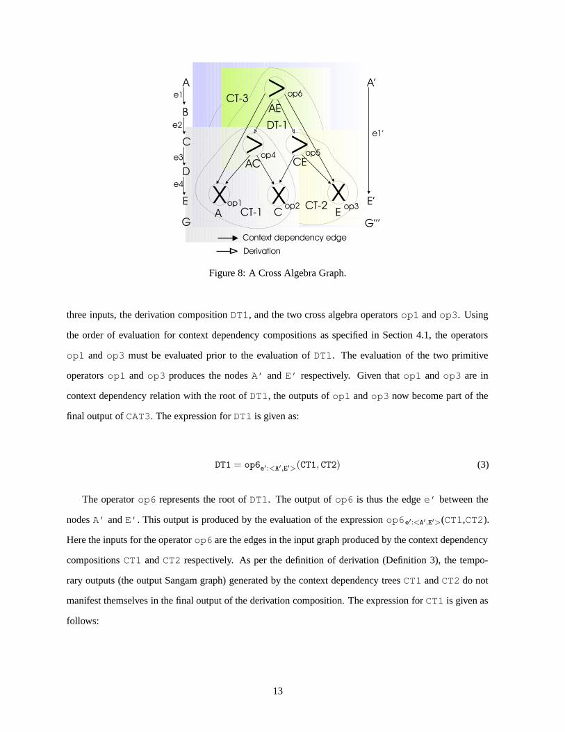
Figure 8: A Cross Algebra Graph.
three inputs, the derivation composition DT1, and the two cross algebra operators op1 and op3. Using
the order of evaluation for context dependency compositions as specified in Section 4.1, the operators
op1 and op3 must be evaluated prior to the evaluation of DT1. The evaluation of the two primitive
operators op1 and op3 produces the nodes A’ and E’ respectively. Given that op1 and op3 are in
context dependency relation with the root of DT1, the outputs of op1 and op3 now become part of the
final output of CAT3. The expression for DT1 is given as:
DT1 = op6e′:<A′,E′>(CT1, CT2) (3)
The operator op6 represents the root of DT1. The output of op6 is thus the edge e’ between the
nodes A’ and E’. This output is produced by the evaluation of the expression op6e′:<A′,E′>(CT1,CT2).
Here the inputs for the operator op6 are the edges in the input graph produced by the context dependency
compositions CT1 and CT2 respectively. As per the definition of derivation (Definition 3), the tempo-
rary outputs (the output Sangam graph) generated by the context dependency trees CT1 and CT2 do not
manifest themselves in the final output of the derivation composition. The expression for CT1 is given as
follows:
13

CT1 = op4eTemp1:<A′,C′>(e1 :< A, B >, e2 :< B, C >), (op1A′(A) op2C′(C)) (4)
Operator op6 consumes the edge eTemp1 produced by the context dependency composition CT1 as
well as the edge eTemp2, the output produced by CT2. The Sangam graph G’ is an intermediate Sangam
graph and is discarded, i.e, G’ and the edge eTemp1:<A’, C’> do not appear in the final output of op6.
Similar to CT1, the expression for CT2 is given as:
CT2 = op5eTemp2:<C′,E′>(e3 :< C, D >, e4 :< D, E >), (op2C′(C) op3E′(E)) (5)
To summarize the above example (Figure 8), the context dependency compositions CT1 and CT2
produce two intermediate Sangam graphs G’ and G’’ that smooth the edges e1 and e2 to produce edge
eTemp1 and smooth edges e3 and e4 to produce edge eTemp2 respectively. The operator op6 then gets
its inputs from CT1 and CT2 and produces the edge e’:<A’, E’>. The operator op6 also participates
in the composition CAT3, the output of which is the final Sangam graph G’’’ with nodes A’, E’ and
the edge e’:<A’, E’>. Thus, the CAT in Figure 8 operates on the input Sangam graph G and produces
as output the Sangam graph G’’’.
As shown by the example above, operators may participate in more than one context dependency
or derivation composition, i.e., they may appear multiple times in the CAT algebra expression. These
shared operators are evaluated only once during the evaluation of the complete CAT expression, and hence
contribute output once (versus multiple times) in the evaluation of the CAT. We say that two operators are
the same if they observe the following conditions.
Definition 4 (Same Operators) Two operators opi and opj are identified as being the same in one CAT,
if they have the (1) same mapping type (cross, smooth, etc.); (2) same input node or edge (from the same
input Sangam graph G) as identified by its label and identifier; and (3) produce as output the same node
or edge in the Sangam graph G’ based on its label and identifier.
Definition 5 (Evaluation Semantics of Shared Operators) If two operators opi and opj are the same
as per Definition 4, then they are termed shared operators. Each shared operator is evaluated once, and
14

contributes directly2 at most once to the final output graph G’ produced by the CAT.
Definition 6 (CAT) A CAT is an expression that operates on one or more input Sangam graphs G andproduces one or more output Sangam graph G’ such that:
CATo(outo)(ino) =
DTi(outi)(ini) where DTi is as per Definition 3CTi(outi)(ini) where CTi is as per Definition 2
(CATj(outj)(inj )) ,((CATk(outk)(ink))) where CATj is parent of CATk
such that CATk must be evalu-ated prior to the evaluation ofCATj and outo = outj
⋃
out†k .opj(outj )
(CATk(outk)(ink)) where opj derives its input inj
from the output outk producedby CATk, and outo = out‡j .
opj(outj )((CATk(outk)(ink)),(CATl(outl)(inl))) where opj derives its input inj
from the outputs outk and outlproduced by CATk and CATl
respectively, and outo = outγj .
† = A context dependency edge is added from the root opj of CATj to the root opk of CATk.‡ = A derivation edge is added from opj to opk, the root of CATk.γ = A derivation edge is added from opj to opk and opl, the roots of CATk and CATl respectively.
Based on the definition of a CAT (Definition 6), we now define a cross algebra graph (CAG). Intu-
itively, a CAG is a collection of cross algebra trees that may operate on possibly disjoint input graphs to
produce possibly disjoint output graphs.
Definition 7 (CAG) A cross algebra graph (CAG) is an expression that operates on one or more inputSangam graphs G and produces one or more output Sangam graph G’ such that:
CAGo(outo)(ino) =(CATj(outj)(inj )) [ (CATk(outk)(ink))]
+ where CATj and CATk are sib-ling CATs such that outo = outj⋃
outk
2Some other operator opk may derive from it. The output of operator opk may appear in the final output.
15
4.4 Summary
To summarize, in this section we have introduced two techniques for composing the cross algebra oper-
ators, namely the context dependency composition and the derivation composition. The context depen-
dency composition enables several algebra operators to collaborate and jointly operate on sub-graphs to
produce one combined output graph. The derivation composition enables the nesting of several algebra
operators wherein output of one or more operators becomes the input of another operator. Derivation and
context dependency can in turn be combined together to produce larger, more complex transformations.
In this section, we have presented rules governing their combination.
5 Transformation Model Generators
We recognize two important aspects of any modeling framework: (1) modeling of transformations is not
always an easy task and may possibly be labor-intensive; and (2) there exists possibly a set of commonly
used transformations. To encourage re-usability we propose a library of transformation generators. Each
generator in the library encodes an algorithm for generating a transformation model of a given “style” for
any given input graph. That is, the input graph is provided as a parameter to the generator. In this section,
we now present one such generator, the basic-inlining generator, based on the basic inlining technique
proposed by Shanmugasundram et al. [SHT+99]. The basic inlining technique translates an XML DTD
and associated document into a relational schema and data. It essentially inlines as many descendants of
an element as possible into a single relation. As an XML document can be rooted at any element, this
technique is applied for all elements in a DTD and hence creates relations for every element.
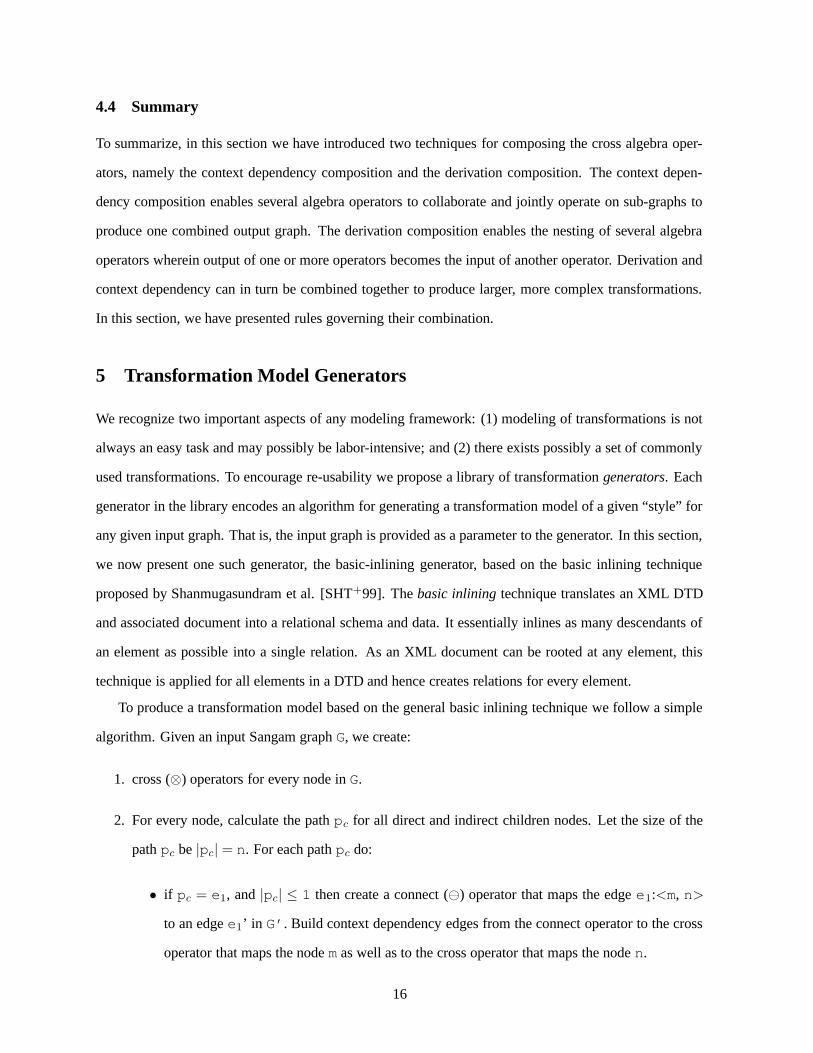
To produce a transformation model based on the general basic inlining technique we follow a simple
algorithm. Given an input Sangam graph G, we create:
1. cross (⊗) operators for every node in G.
2. For every node, calculate the path pc for all direct and indirect children nodes. Let the size of the
path pc be |pc| = n. For each path pc do:
• if pc = e1, and |pc| ≤ 1 then create a connect () operator that maps the edge e1:<m, n>
to an edge e1’ in G’. Build context dependency edges from the connect operator to the cross
operator that maps the node m as well as to the cross operator that maps the node n.
16

ITEM(id VARCHAR(10) NOTNULL, featured VARCHAR(100), item.location VARCHAR(200),item.mailbox.id VARCHAR(10), item.name.lastName VARCHAR(200), item.name.firstName VAR-CHAR(200))
ITEM.MAILBOX.MAIL(text VARCHAR(800), item.mailbox.mail.from VARCHAR(50),item.mailbox.mail.to VARCHAR(50), item.mailbox.mail.date VARCHAR(8), parentId INTEGER)
LOCATION(location VARCHAR(200), parentId INTEGER)
MAILBOX(id VARCHAR(10), parentId INTEGER)
MAIL(text VARCHAR(800), from VARCHAR(50), to VARCHAR(50), date VARCHAR(8), parentIdINTEGER)
FROM(from VARCHAR(200), parentId INTEGER)
TO(to VARCHAR(200), parentId INTEGER)
DATE(date VARCHAR(200), parentId INTEGER)
NAME(firstName VARCHAR(200), lastName VARCHAR(200), parentId INTEGER)
FIRSTNAME(firstName VARCHAR(200), parentId INTEGER)
LASTNAME(lastName VARCHAR(200), parentId INTEGER)
Figure 9: Fragment of Relational Schema Generated by Mapping the XMark Benchmark Schema ofFigure 1 using the Basic Inlining Technique [STZ+99]. All field sizes are set during the mapping ofatomic nodes which are not shown here.
• if p= e1.e2, and |p| = 2, then create a smooth operator that takes as input the two edges
e1 and e2, and produces one edge e’ in G’. Build context dependency edges from the
operator to the ⊗ operators that map the end-points (nodes) of the path.
• if p = e1.e2.. . ..en, and |p| > 2, then to inline the edges and produce one edge e’:<m’,
n’> where m’ and n’ are the mapped end-points of the path p, build derivation trees of
smooth and connect operators in the manner detailed below.
– Break the input path p into paths p1, p2 . . . pm of size 2 each. Create a operator
for every such pair of edges. For paths of odd size, create a connect operator for the
singleton path pm with |pm| = 1 that is left over. Create context dependency edges
between the operators as described in step 3. An intermediate G’’ is created such that
the size of the path p’ in G’’ is |p’| = n/2 if |p| was even and |p’| = n/2 + 1 if |p|
17
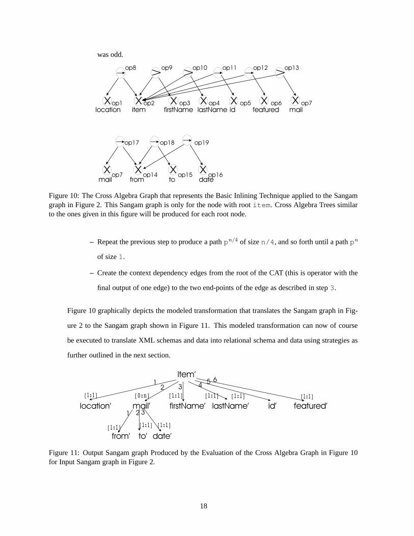
was odd.
Figure 10: The Cross Algebra Graph that represents the Basic Inlining Technique applied to the Sangamgraph in Figure 2. This Sangam graph is only for the node with root item. Cross Algebra Trees similarto the ones given in this figure will be produced for each root node.
– Repeat the previous step to produce a path pn/4 of size n/4, and so forth until a path pn
of size 1.
– Create the context dependency edges from the root of the CAT (this is operator with the
final output of one edge) to the two end-points of the edge as described in step 3.
Figure 10 graphically depicts the modeled transformation that translates the Sangam graph in Fig-
ure 2 to the Sangam graph shown in Figure 11. This modeled transformation can now of course
be executed to translate XML schemas and data into relational schema and data using strategies as
further outlined in the next section.
Figure 11: Output Sangam graph Produced by the Evaluation of the Cross Algebra Graph in Figure 10for Input Sangam graph in Figure 2.
18

Item’(id’ VARCHAR(10) NOTNULL, featured’ VARCHAR(100) NOTNULL, location’ VARCHAR(200)NOTNULL, firstName’ VARCHAR(200), lastName’ VARCHAR(200))
Item.mail’(from’ VARCHAR(50), to’ VARCHAR(50), date’ VARCHAR(8), CONSTRAINT fk id FOR-EIGN KEY (id’) REFERENCES Item’(id’))
Figure 12: The Relational Schema Produced by the Translation of the Sangam graph in Figure 11.
6 Execution Strategies for Modeled Transformations
In Sections 3 and 4 we have introduced the bricks and the mortar of our translation modeling framework,
and shown how large complex transformations can be modeled in the same. In this section, we briefly
describe how the cross algebra expressions representing the modeled transformations can be executed.
The execution of the cross algebra expression here implies the transformation of the source schema and
data as per the modeled transformation to produce the target schema and data. As stated in Section 1 there
are many possible strategies for executing these modeled transformations. These strategies range from
mapping the modeled transformation into query languages such as SQL [ANS92] or XQuery [FFM+01]
to applying execution algorithms directly using the transformation model. To keep the discussion sim-
ple we now sketch out a customized algorithm for executing the cross algebra expressions as shown in
Figure 13.
A cross algebra graph (CAG) can be viewed as a forest of nested context dependency and derivation
compositions. Each composition CATi of the CAG can be evaluated independently of any other compo-
sition CATj of the CAG. To evaluate each individual CAT, we use post-order evaluation, i.e., all children
operators opj of an operator opk are evaluated prior to the evaluation of opk.
Figure 13 gives the algorithm for evaluating the cross algebra graph. Here, to facilitate evaluation of
shared operators, each operator opj is marked “visited” the first time it is evaluated, and its local output
is cached. If the operator opj is re-visited, no further evaluation of opj is done, instead its cached output
is returned to the invoking parent operator opi. Evaluation of the tree terminates with the evaluation of
the root operator3 .
3Proof of termination can be found in [Cla02].
19

function EvaluateCAG (input: CAG cag, input: Sangam graph G,output: Sangam graph G’)
List roots← cag.getRoots()while (roots ! = null)
operator op← roots.getNext()EvaluateCAT (op, G, G’)
function EvaluateCAT (input: Operator op, input: Sangam graph G,output: Sangam graph G’)
if (!op.hasChildren())
Sangam graph G’← op.evaluate(G, G’)op.markDone()Sangam graph out← G’ // cache the local outputreturn localG’
while (op.hasChildren()) operator opC← op.getNextChild()if (e:<op, opC> = derivation)
SAG Glocal ← EvaluateCAT (opC, G, G’)SAG G’← op.evaluate(Glocal, G’)op.markDone()SAG out← G’ // local cached outputreturn G’
elseif (e:<op, opC> = context dependency)SAG Glocal ← EvaluateCAT (opC, G, G’)SAG G’local ← op.evaluate(G, G’)SAG G’← Glocal
⋃
G’local
op.markDone()SAG out← G’local // local cached outputreturn G’
Figure 13: The Evaluation Algorithm for a Cross Algebra Graph.
7 Sangam - The Prototype System
7.1 Architectural Overview of Sangam
The Sangam system incorporating all the techniques discussed in the paper has been developed using
Java technology and a variety of tools such as the JAXP [Sys01] for parsing XML documents and the
DTD-Parser [Wut01] for parsing the DTDs. Figure 14 gives an architectural overview of the system.
Here SAG-Loader translates XML and relational schema and data into Sangam graphs ; CAG-Builder
20

houses the library of transformations and builds transformation models based on the chosen generators for
the given input Sangam graph ; the CAG-Evaluator evaluates the CAG; and lastly the CAG-Generator
is able to translate the given output Sangam graph into a relational or XML schema and data.
Figure 14: Architecture of Sangam
7.2 Experimental Validation of Sangam
We have conducted several experiments to measure: (1) the practicality of the Sangam graph model and
the cross algebra graph as presented in Sections 2 and 3 respectively; and (2) the costs for the different
modules. However, due to space constraints we report only a summary of our results, while a full set of
experiments can be found in [Cla02].
All experiments were conducted on a Pentium IV, 933MHz, 256Mb RAM system running Debian
Linux, kernel version 2.2.19, using the Sangam prototype system described in Section 7.1. The Sangam
system itself was built using the Java JDK, version 1.3.1. To store relational data we used Oracle 9i
running on Debian Linux, kernel version 2.2.19.
For each input Sangam graph, we built the Cross Algebra Graphs (CAGs) that represent either (1) an
identical transformation, in which case the input Sangam graph is identical to the output Sangam graph;
(2) a basic inline transformation; or (3) a shared inline transformation4 . Figure 15 depicts the evaluation
time for the ident and the inline CAGs. In general, we found that the ident performed better than the inline.
This can be attributed to the fact that an inline CAG contains smooth operators which are more expensive
than the connect and cross operators contained in the ident CAG. Figure 16 depicts the experimental
results for a larger Sangam graph.
4We found the loading time of the basic and shared inlining to be almost identical. We thus report only the results of thebasic inlining.
21

0
200000
400000
600000
800000
1e+06
1.2e+06
0 2000 4000 6000 8000 10000 12000 14000 16000
Tim
e in
Mill
isec
onds
Input Extent: Number of Objects
Evaluation Time vs. Input Extent
inlineident
Figure 15: The Time Taken to Evaluate Identand Inline CAGs as the Extent Size of the InputSangam Graph Loaded from the personal.dtdis Varied.
0
20000
40000
60000
80000
100000
120000
140000
1 1.5 2 2.5 3 3.5 4 4.5 5
Tim
e in
Mill
isec
onds
XML Size in MegaBytes
Evaluation Time vs. XML Size
Inline CAG Evaluation TimeIdent CAG Evaluation Time
Figure 16: The Time Taken to Evaluate Identand Inline CAGs as the Extent Size of the InputSangam Graph Loaded from the auction.dtd isVaried.
Based on our experimental results (detailed elsewhere) [Cla02], we can draw the following conclu-
sions: (1) the evaluation times for the cross and connect operators increase linearly with a linear
increase in input extent size; (2) the evaluation time for the smooth and subdivide operators in-
creases polynomially with a linear increase in input extent size; and (3) the evaluation time for a CAG, in
general, is a polynomial function of the operator types and the size of the CAG.
8 Related Work
Schema Integration and Data Transformation. There is extensive literature under the umbrella of
schema transformation and integration [HMN+99b, MZ98, FK99, MIR93, CJR98, RR87]. However, this
work is typically specific to either an application domain or to a particular data model and does not deal
with meta-modeling [AT96, BR00, PR95, RR87]. Recent work related to ours are Clio [HMN+99b] a
research project at IBM’s Almaden Research Center and work by Milo and Zohar [MZ98]. Clio, a tool
for creating mappings between two data representations semi-automatically with user inputs, focuses on
supporting querying of data in either the source or the target representation and on just in time cleansing
and transformation of data. Milo et al. [MZ98] have looked at the problem of data translations based
on schema-matching. They follow an approach similar to Atzeni et al.[AT96] and Papazoglou et al.
[PR95], but not at the meta-level, in that they define a set of translation logic rules to enable discovery
of relationships between two application schemas. Bernstein et al. [BR00] have also proposed a meta-
22
modeling framework to represent schemas in a common data model to facilitate a host of tools such as the
match operator which produces a set of matches between two given schemas. While we share this vision,
our focus is more on the representation and the execution of transformations that may be produced either
by such matches or by a user via a GUI. In fact, based on the discussion with the authors of [BR00], their
meta-model can be extended with a makemap meta-operator to capture the semantics of our work.
We can directly make use of translation algorithms from the literature, such as the algorithms for
translating between an XML-DTD and relational schema [FK99] or mapping rules [MZ98] or output
from match operators [BR00]. That is, we can develop generators that capture such specific algorithms,
and then generate separate transformation models that can be executed. Work on equivalence of the trans-
lations between models [MIR93] is of particular importance as such properties could also be established
for the cross algebra.
Mapping XML Models to Other Data Models. Currently there are numerous projects that deal with
the persistent storage of XML documents [ZLMR01, FK99, SHT+99, CFLM00]. Shanmugasundram et
al. [SHT+99] presented the storage of XML documents with DTD in a relational system and cataloged
the limitations of relational systems in doing so. We utilize their translation algorithms basic inlining and
shared inlining as examples in our work. In the same vein, Florescu et al. [FK99] present a comparative
evaluation of eight mapping schemes for storing XML documents in relational databases. Zhang et al.
[ZLMR01] present one fixed mapping for storing XML documents (with DTD) in relational systems.
Catania et al. [CFLM00] present the use of object databases to efficiently store XML documents with
DTDs.
9 Conclusions
In this paper, we have presented our flexible, extensible and re-usable transformation modeling frame-
work. This framework has the advantage of allowing users to model complex translations using the basic
building blocks that we have presented in this paper, and then with a click of a button generating and
executing code that would perform the data translation. Concretely, we make the following contributions:
• The Building Blocks:
– Cross Algebra Operators: These operators represent the set of primitive operations for the
23

class of linear graph transformations.
– Composition Techniques: To allow users to model larger and more complex transformations,
we have defined in this paper two composition techniques, context dependency and derivation
compositions, to allow for ordered and nested compositions respectively.
• Transformation generators: To increase the re-usability of our framework, we have introduced the
concept of a library of transformation generators. Each generator captures specific logic to produce
transformation models for a given input graph.
• Execution Strategy: A modeled transformation can be evaluated using many different techniques,
ranging from mapping to query languages to customized algorithms. In this paper we present
a Sangam native algorithm for evaluating the modeled transformation to translate the underlying
data, which has been implemented in our system.
• Implementation: A prototype of this framework has been built and several aspects of its perfor-
mance evaluated. The framework has been built in Java, JDK 1.4, and various other Java tools.
More details can be found in [Cla02].
While in this paper, we make substantial contributions towards providing a transformation framework,
we believe this is just the tip of the iceberg. Some of the possible extensions to this work include extending
the framework to handle a larger class of transformations beyond the linear transformations, investigating
optimization strategies for the evaluation of the modeled transformations, and the development of a tool
set to increase the utility of such a framework.
References[ANS92] ANSI Standard. The SQL 92 Standard. http://www.ansi.org/, 1992.[AT96] P. Atzeni and R. Torlone. Management of Multiple Models in an Extensible Database Design Tool. In
Peter M. G. Apers and et al., editors, Advances in Database Technology - EDBT’96, Avignon, France,March 25-29, LNCS. Springer, 1996.
[BCVB01] S. Bergamaschi, S. Castano, M. Vincini, and D. Beneventano. Semantic integration of heterogeneousinformation sources. Data and Knowledge Engineering, 36(3):215–249, 2001.
[BHP94] M.W. Bright, A.R. Hurson, and S. H. Pakzad. Automated Resolution of Semantic Heterogeneity inMultidatabases. TODS, 19(2):212–253, 1994.
[BM01] J. Berlin and A. Motro. AutoPlex: Automated Discovery of Content for Virtual Databases. In CoopIS,pages 108–122, 2001.
[BR00] P. A. Bernstein and E. Rahm. Data Warehouse Scenarios for Model Management. In InternationalConference on Conceptual Modeling, 2000.
[CFLM00] B. Catania, E. Ferrari, A. Levy, and A. Meldelzon. XML and Object Technology. In ECOOPWorkshop on XML and Object Technology, LNCS 1964, pages 191–202, 2000.
24
[CJR98] K.T. Claypool, J. Jin, and E.A. Rundensteiner. SERF: Schema Evolution through an Extensible, Re-usable and Flexible Framework. In Int. Conf. on Information and Knowledge Management, pages314–321, November 1998.
[Cla02] K.T. Claypool. Managing Change in Databases. PhD thesis, Worcester Polytechnic Institute, May2002.
[DR02] Hong Hai Do and E. Rahm. COMA - A System for Flexible Combination of Schema MatchingApproaches. In vldb, 2002.
[FFM+01] P. Fankhauser, M. Fernandez, A. Malhotra, M. a Rys, J. Simeon, and P. Wadler. XQuery 1.0 FormalSemantics. http://www.w3c.org/TR/2001/query-semantics, June 2001.
[FK99] D. Florescu and D. Kossmann. Storing and Querying XML Data Using an RDBMS. In Bulletin ofthe Technical Committee on Data Engineering, pages 27–34, Sept. 1999.
[GL98] S. Gobel and K. Lutze. Development of Meta Databases for Geospatial Data in the WWW. InACM-GIS, pages 94–99, 1998.
[GY98] J. Gross and J. Yellen. Graph Theory and it Applications. CRC Press, 1998.[HMN+99a] L.M. Haas, R.J. Miller, B. Niswonger, M.T. Roth, P. Schwarz, and E.L. Wimmers. Transforming Het-
erogeneous Data with Database Middleware: Beyond Integration. IEEE Data Engineering Bulletin,22(1):31–36, 1999.
[HMN+99b] L.M. Haas, R.J. Miller, B. Niswonger, M.T. Roth, P. Schwarz, and E.L. Wimmers. Transforming Het-erogeneous Data with Database Middleware: Beyond Integration. IEEE Data Engineering Bulletin,22(1):31–36, 1999.
[MBR01] J. Madhavan, P. Bernstein, and E. Rahm. Generic Schema Matching with Cupid. In vldb, pages49–58, 2001.
[MIR93] R. J. Miller, Y. E. Ioannidis, and R. Ramakrishnan. The Use of Information Capacity in SchemaIntegration and Translation. In Int. Conference on Very Large Data Bases, pages 120–133, 1993.
[MR83] L. Mark and N. Roussopoulos. Integration of Data, Schema and Meta-Schema in the Context ofSelf-Documenting Data Models. In Carl G. Davis, Sushil Jajodia, Peter A. Ng, and Raymond T. Yeh,editors, Proceedings of the 3rd Int. Conf. on Entity-Relationship Approach (ER’83), pages 585–602.North Holland, 1983.
[MZ98] T. Milo and S. Zohar. Using Schema Matching to Simplify Heterogeneous Data Translation. InAshish Gupta, Oded Shmueli, and Jennifer Widom, editors, VLDB’98, Proceedings of 24rd Interna-tional Conference on Very Large Data Bases, August 24-27, 1998, New York City, New York, USA,pages 122–133. Morgan Kaufmann, 1998.
[PR95] M.P. Papazoglou and N. Russell. A Semantic Meta-Modeling Approach to Schema Transformation.In CIKM ’95, pages 113–121. ACM, 1995.
[RR87] A. Rosenthal and D. Reiner. Theoretically Sound Transformations for Practical Database Design.In Salvatore T. March, editor, Entity-Relationship Approach, Proceedings of the Sixth InternationalConference on Entity-Relationship Approach, New York, USA, November 9-11, 1987, pages 115–131,1987.
[SHT+99] J. Shanmugasundaram, G. He, K. Tufte, C. Zhang, D. DeWitt, and J. Naughton. Relational Databasesfor Querying XML Documents: Limitations and Opportunities. In Proceedings of 25th InternationalConference on Very Large Data Bases (VLDB’99), pages 302–314, 1999.
[STZ+99] J. Shanmugasundaram, K. Tufte, C. Zhang, G. He, D. DeWitt, and J.F. Naughton. RelationalDatabases for Querying XML Documents: Limitations and Opportunities. In Malcolm P. Atkinsonand Maria E. Orlowska and Patrick Valduriez and Stanley B. Zdonik and Michael L. Brodie, editor,VLDB’99, Proceedings of 25th International Conference on Very Large Data Bases, September 7-10,1999, Edinburgh, Scotland, UK, pages 302–314. Morgan Kaufmann, 1999.
[Sys01] Java Systems. The jaxp 1.1.1parser. http://java.sun.com, November 2001.[SYU99] T. Shimura, M. Yoshikawa, and S. Uemura. Storage and Retrieval of XML Documents using Object-
Relational Databases. In Int. Conference and Workshop on Database and Expert Systems Applica-tions, pages 206–217. Springer-Verlag, 1999.
[Wut01] M. Wutka. The dtd parser. http://www.wutka.com, March 2001.[ZLMR01] X. Zhang, W-C. Lee, G. Mitchell, and E. A. Rundensteiner. Clock: Synchronizing Internal Relational
Storage with External XML Documents. In ICDE-RIDE 2001, 2001.
25


![Sagar [ Sangam Electronic ]](https://static.fdocuments.net/doc/165x107/55cf9291550346f57b97825d/sagar-sangam-electronic-.jpg)