Sandvik Idler
60
Engineering user reference and guidelines book HA200 Idlers design manual
-
Upload
rajeevkumarrajeev -
Category
Documents
-
view
184 -
download
2
description
Sandvik Idler
Transcript of Sandvik Idler

Engineering user reference and guidelines book
HA200 Idlers design manual


Sandvik conveyor idlersTransportation systems depend on the consistant functioning of conveyor components. Sandvik’s complete conveyor offering includes components with an emphasis on performance and reliability, for light, medium and heavy-duty applications. Through innovation in design and manufacturing techniques, we provide operations and maintenance personnel with products that support modern mining practices, both asoriginal components or as replacements in existing systems.
HEAVY DUTY TRANSPORTATION
Highly demanding conditions for rollers, frames or complete idlers (rollers and frames) are often encountered in stripping and handling of overburden material and in processing and transportation of coal, iron ore, and other mined materials. Individual conveyors often transport 20,000 tonnes per hour and overland conveyors can have up to 30,000 rollers in a single system. Sandvik’s component business has grown up in this environment; we understand the importance of reliability and the cost of failures.
Thanks to our global strength, and close-to-customers manufacturing on several continents, our rollers and idlers are delivered to suit a range of differing standards and specifications including European, Australian, Asian, African and American standards and dimensions.
Specialised Solutions
Sandvik has developed a wide range of specialised products and services for modern materials handling applications. As a market leader Sandvik has worked with our key customers to provide products that are targeted to meet the demands of a varied industry base.
Reduced Noise
The requirement to reduce total noise emission levels has necessitated the development of a range of conveyor idlers that reduce the noise generated from a conveyor system. Sandvik excels at providing low noise rollers that meet this requirement and is able to provide products that can provide a 75% reduction in the noise output of conveyor idlers.
Reduced Weight
Innovative designs and the use of alternative materials have provided Sandvik with a leading edge in the conveyor industry. As the world continues to work towards improving the safety of its workforce, Sandvik is able to provide rollers that have up to a 50% reduction in unit mass. Therefore the risk associated with installing and replacing conveyor rollers has been minimised.
Reduced Downtime
Sandvik has manufactured conveyor components for in excess of 50 years. We have refined our products to the point that they are the market leaders in product performance reliability.
Install a Sandvik idler with the confidence it will provide years of trouble free performance - often in excess of 15 years service in the most demanding of applications.
1
ContentsThe range of Sandvik idlers 2
HA200 moulded end cap rollers 4
Idler terminology and types 6
Sandvik HA200 identification system 9
Electronic tag roller identification 11
The design concept 12
The HA200 design features 13
The engineering concept 14
The HA200 manufacturing concept 16
Quality in action 17
HA200 standards and tolerances 18
Recommended location Head & Tail Pulleys 20
Belt tracking notes 23
HA200 idler selection procedure 24
HA200 idler selection guide 25
Consideration of additional loads 27
Consideration of base member size 29
Notes on impact idler selection 30
CEMA standards 31
Sample HA200 idler selection 32
Design data sheet 33
HA200 Idler load charts 34
Research & development 42
Low noise roll development 43
Jackdown frames 44
Useful data 45
Material characteristics 47
Cross-sectional area 52
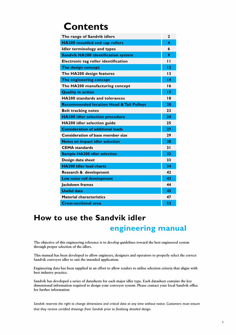
How to use the Sandvik idler engineering manual
The objective of this engineering reference is to develop guidelines toward the best engineered system through proper selection of the idlers.
This manual has been developed to allow engineers, designers and operators to properly select the correct Sandvik conveyor idler to suit the intended application.
Engineering data has been supplied in an effort to allow readers to utilise selection criteria that aligns with best industry practice.
Sandvik has developed a series of datasheets for each major idler type. Each datasheet contains the key dimensional information required to design your conveyor system. Please contact your local Sandvik office for further information
Sandvik reserves the right to change dimensions and critical data at any time without notice. Customers must ensure
that they receive certified drawings from Sandvik prior to finalising detailed design.
2
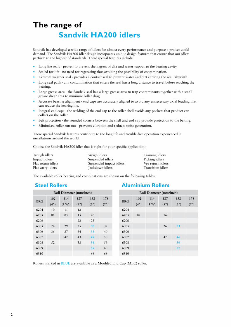
The range of Sandvik HA200 idlers
Sandvik has developed a wide range of idlers for almost every performance and purpose a project could demand. The Sandvik HA200 idler design incorpoates unique design features that ensure that our idlers perform to the highest of standards. These special features include:
• Long life seals - proven to prevent the ingress of dirt and water vapour to the bearing cavity.
• Sealed for life - no need for regreasing thus avoiding the possibility of contamination.
• External weather seal - provides a contact seal to prevent water and dirt entering the seal labyrinth.
• Long seal path - any contamination that enters the seal has a long distance to travel before reaching the bearing.
• Large grease area - the Sandvik seal has a large grease area to trap contaminants together with a small grease shear area to minimise roller drag.
• Accurate bearing alignment - end caps are accurately aligned to avoid any unnecessary axial loading that can reduce the bearing life.
• Integral end caps - the welding of the end cap to the roller shell avoids any pockets that product can collect on the roller.
• Belt protection - the rounded corners between the shell and end cap provide protection to the belting.
• Minimised roller run out - prevents vibration and reduces noise generation.
These special Sandvik features contribute to the long life and trouble-free operation experienced in installations around the world.
Choose the Sandvik HA200 idler that is right for your specific application:
Trough idlers Weigh idlers Training idlers Impact idlers Suspended idlers Picking idlersFlat return idlers Suspended impact idlers Vee return idlersFlat carry idlers Jackdown idlers Transition idlers
The available roller bearing and combinations are shown on the following tables.
Roll Diameter (mm/inch) Roll Diameter (mm/inch)
BRg102 114 127 152 178
BRg102 114 127 152 178
(4”) (4 1/2”) (5”) (6”) (7”) (4”) (4 1/2”) (5”) (6”) (7”)
6204 10 11 12 6204
6205 01 05 15 20 6205 02 16
6206 22 23 6206
6305 24 29 25 30 32 6305 26 33
6306 36 37 34 35 40 6306
6307 42 43 45 50 6307 47 46
6308 52 53 54 59 6308 56
6309 55 60 6309 57
6310 68 69 6310
Rollers marked in BLUE are available as a Moulded End Cap (MEC) roller.
Steel Rollers Aluminium Rollers
3
Roll Diameter (mm/inch) Roll Diameter (mm/inch)
BRg133 159 178
BRg127 152 178
(5 1/4”) (6 1/4”) (7”) (5”) (6”) (7”)
6204 6204
6205 15 6205 15 61
6206 6206
6305 6305 30
6306 6306
6307 30/45 50 6307 45 50
6308 59 6308
6309 6309
6310 6310
The Sandvik HA200 roller series defines the Roll Diameter and Bearing size. The tables show the respective Sandvik roller series that are available for each roller type. For example a 127mm (5”) diameter steel roller with a 6305 bearing is a Sandvik series 25 roller.
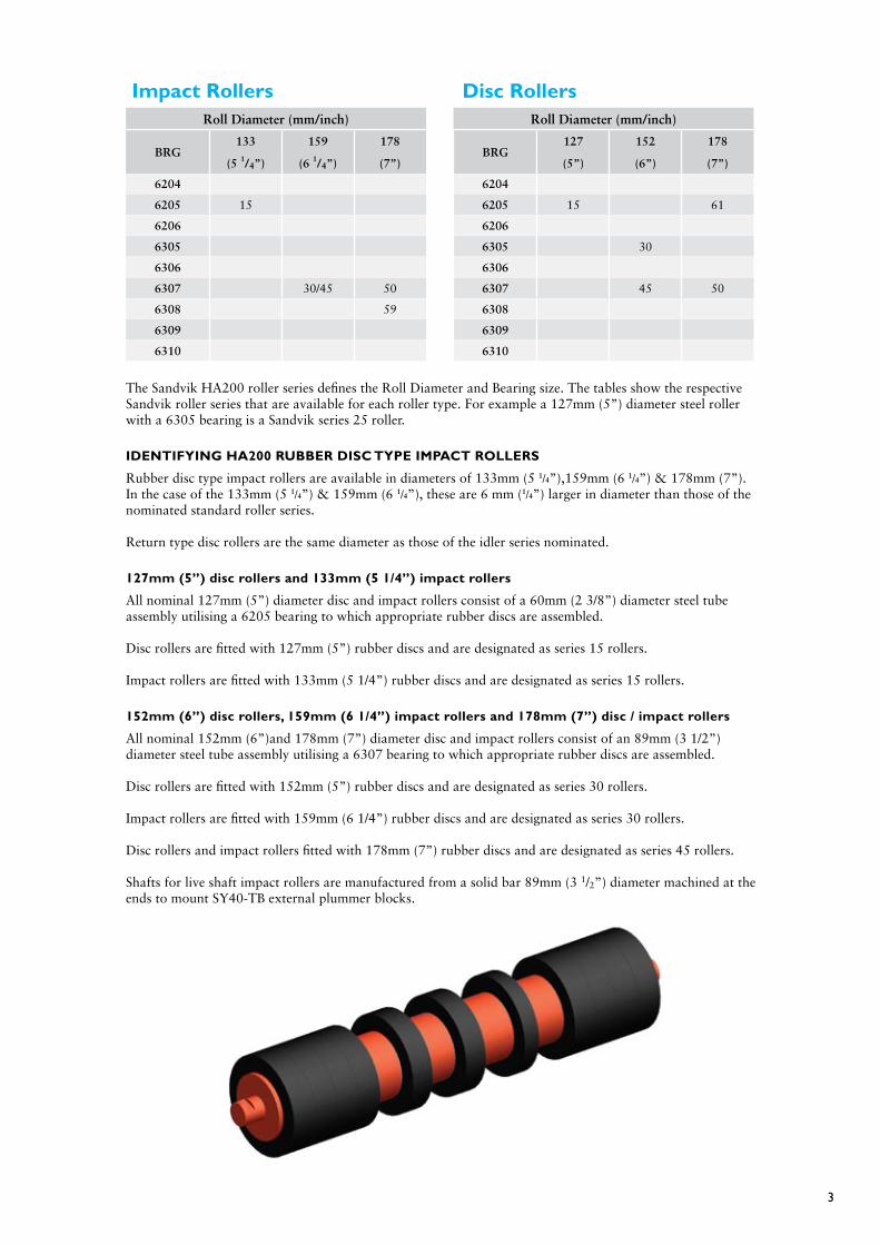
IDENTIfYINg HA200 RUBBER DISC TYPE IMPACT ROLLERS
Rubber disc type impact rollers are available in diameters of 133mm (5 1/4”),159mm (6 1/4”) & 178mm (7”). In the case of the 133mm (5 1/4”) & 159mm (6 1/4”), these are 6 mm (1/4”) larger in diameter than those of the nominated standard roller series.
Return type disc rollers are the same diameter as those of the idler series nominated.
127mm (5”) disc rollers and 133mm (5 1/4”) impact rollers
All nominal 127mm (5”) diameter disc and impact rollers consist of a 60mm (2 3/8”) diameter steel tube assembly utilising a 6205 bearing to which appropriate rubber discs are assembled.
Disc rollers are fitted with 127mm (5”) rubber discs and are designated as series 15 rollers.
Impact rollers are fitted with 133mm (5 1/4”) rubber discs and are designated as series 15 rollers.
152mm (6”) disc rollers, 159mm (6 1/4”) impact rollers and 178mm (7”) disc / impact rollers
All nominal 152mm (6”)and 178mm (7”) diameter disc and impact rollers consist of an 89mm (3 1/2”) diameter steel tube assembly utilising a 6307 bearing to which appropriate rubber discs are assembled.
Disc rollers are fitted with 152mm (5”) rubber discs and are designated as series 30 rollers.
Impact rollers are fitted with 159mm (6 1/4”) rubber discs and are designated as series 30 rollers. Disc rollers and impact rollers fitted with 178mm (7”) rubber discs and are designated as series 45 rollers.
Shafts for live shaft impact rollers are manufactured from a solid bar 89mm (3 1/2”) diameter machined at the ends to mount SY40-TB external plummer blocks.
Impact Rollers Disc Rollers

4
HA200 moulded end cap rollers
The Sandvik MEC roller is the result of
extensive research and development by the
Sandvik conveyor component R&D team. The
roller construction and manufacture contains
several unique features that produce significant
improvements over traditional rollers.
The MEC roller is ideally suited for applications
requiring a corrosion resistant roller that has low
noise characteristics. Typical applications include
ports, coal handling prep plants and installations
that are located close to populated areas or
operate in corrosive environments.
features and benefits
• The MEC delivers a roller that is low noise
with reduced vibration.
• The roller tube is mechanically located and
fixed to the end cap – the risk of separation
of the end cap from the tube is eliminated.
• Efficient Sandvik sealing provides years of
trouble free operation with a low roller drag.
• Non metallic end cap is resistant to corrosion
and weathering.
• When fitted with aluminium tubing the risks
associated with manual handling are reduced.
• Dimensionally identical to standard rollers of
the same diameter / bearing combination.
• The shell to end cap transition provides
additional protection for the belting.
Low Noise
The majority of conveyor roller noise is
generated by the interaction of the conveyor
belt and the surface of the roller. Sandvik has
already developed a machined and balanced
low noise roller that provides excellent levels
of noise reduction over standard rollers. This
precision roller has proven to be very successful
in reducing total conveyor noise. While this
solution has proven to be very sucessful in
reducing noise output, Sandvik has continued
to develop alternative designs with the aim of
delivering noise reductions without the need
for extensive machining processes. The MEC
roller is a result of this research.
The MEC roller, with its unique design and
manufacturing process, provides an excellent low
noise roller without the need for machining or
dynamically balancing.
This is complemented by the use of Sandvik’s
high quality conveyor tube that has
exacting levels dimensional accuracy, especially
in the areas of wall thickness,
roundness (TIR) and straightness.
In addition the non metallic end cap provides
some dampening of vibration which
further reduces the roller noise.
Lightweight and corrosion resistant rollers.
The MEC roller with a steel shell can provide
weight reductions of up to 9% when compared
to a standard steel roller.
Utilising an aluminium shell to a MEC roller can
further reduce the total roller mass as well as the
rotating mass. This will provide a unit
weight reduction of approximately 37% when
compared to a conventional steel roller.
This is especially relevant for rollers installed on
stackers, reclaimers, shiploaders or any other self
supported structure.

5
Corrosion and premature wear can significantly reduce the service life of a conveyor roller. This is
particularly relevant in applications such as ports, coal handling prep plants and conveyors handling
corrosive materials, ie salt etc.
To meet these demanding applications, the Sandvik MEC roller can be fitted with an aluminium shell.
The aluminium shell provides corrosion resistance and the additional advantage of reduced weight.
fitted for life
Sandvik’s unique method of positively locating and fixing the roller shell to the end cap eliminates any
risk of separation of the end cap and shell during operation.
Manufactured tough
The MEC roller is designed to withstand the most arduous of applications. Extensive FEA has ensured
that the finished roller is able to withstand all of the loads and stresses that are experienced with
traditional welded steel rollers. The end cap is manufactured from a material that has exceptional
mechanical and fatigue life characteristics. It is also UV and ozone resistant to withstand years of
service in the harshest of environments.
The Sandvik MEC roller is designed to last.
DESIgN CONSIDERATIONS
The design calculations for selection and specifying MEC rollers is identical to those used for standard
rollers.
The bearing life, shaft deflection, shell wear and roller drag are all identical to a standard Sandvik
HA100 roller.

6
Idler terminology and types
WHAT IS AN IDLER
The industry accepted nomenclature for conveyor idlers is that a conveyor Idler = Frame + Rollers
This distinction is often overlooked and as a result care must be taken when purchasing replacement components that an idler is not specified when only a replacement roller is required.
+ =
COMMON ROLLER/IDLER TYPES
The three common types of conveyor rollers are as follows:
Plain - this roller can be supplied with a steel, aluminium or plastic shell. It is the most common roller type used for general applications.
Impact - these rollers are used where there is heavy impact from lumps of material. Rubber impact disks cushion the roller and conveyor from this impact.
Disc - disc rollers are used on the return side of the conveyor. Rubber or polyurethane discs break up the contact between the belt and the roller and encourage any product that is adheared to the belt to break off and fall away.
IDENTIfICATION PARAMETERS
Sandvik is able to provide replacement rollers for all of our equipment as well as replacement rollers for equipment supplied by others. In order to correctly identify a roller we need to be supplied with the Sandvik part number to allow the roller to be identified.
In the event that the Sandvik part number is not known we will need the following dimensional information to be supplied. If it is not possible to determine the diameter of the shaft in the middle of the roller (diameter E), we will need to be supplied with the operating data to allow a full design check to be carried out.
F ROLL FACE
ØA
G BETWEEN FLATS
H SHAFT LENGTH
ØE
D
ØB
Brg
Out
side
Dia
met
er
Plain Impact Disc
Roller Frame Idler

7
Suspended Return Disc Return
Trough Impact
Retractable (Impact & Plain) Jackdown
Suspended Trainer
Picking Underground Mine Structure
Vee Return Flat Return
TROUgH AND CARRY IDLER TYPES
RETURN IDLER TYPES

8
IDLER MOUNTINg CENTRES
To generally conform with accepted practices, the mounting hole centres listed in the dimensional tables are based on:
Belt Width + 250mm For belts up to and including 1200mm
Belt Width + 300mm For belts over 1200 mm up to and including 1500mm
Belt Width + 400mm For belts 1600mm and above.
INLINE VS OffSET IDLERS
Offset
Offset idlers have slightly overlapping rollers for light duty belts that are susceptible to pinching. They also have self training properties which means they must be installed in the correct orientation.
The moving belt must contact the centre roller first
Inline
Inline idlers are generally used on long conveyors and where thick belts are used.
Direction Of BeltDirection Of Belt
Direction Of BeltDirection Of Belt
9
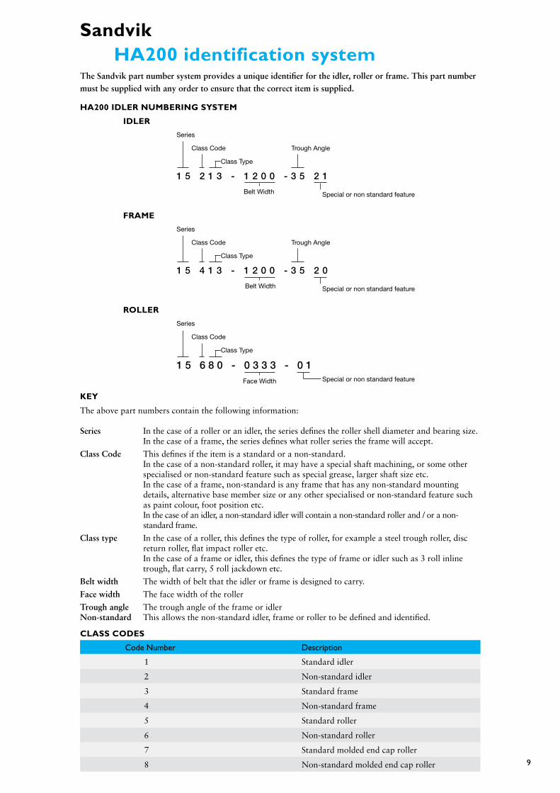
Sandvik HA200 identification systemThe Sandvik part number system provides a unique identifier for the idler, roller or frame. This part number must be supplied with any order to ensure that the correct item is supplied.
KEY
The above part numbers contain the following information:
Series In the case of a roller or an idler, the series defines the roller shell diameter and bearing size. In the case of a frame, the series defines what roller series the frame will accept.
Class Code This defines if the item is a standard or a non-standard. In the case of a non-standard roller, it may have a special shaft machining, or some other specialised or non-standard feature such as special grease, larger shaft size etc. In the case of a frame, non-standard is any frame that has any non-standard mounting details, alternative base member size or any other specialised or non-standard feature such as paint colour, foot position etc. In the case of an idler, a non-standard idler will contain a non-standard roller and / or a non- standard frame.
Class type In the case of a roller, this defines the type of roller, for example a steel trough roller, disc return roller, flat impact roller etc. In the case of a frame or idler, this defines the type of frame or idler such as 3 roll inline trough, flat carry, 5 roll jackdown etc.
Belt width The width of belt that the idler or frame is designed to carry.
Face width The face width of the roller
Trough angle The trough angle of the frame or idlerNon-standard This allows the non-standard idler, frame or roller to be defined and identified.
CLASS CODES
Code Number Description
1 Standard idler
2 Non-standard idler
3 Standard frame
4 Non-standard frame
5 Standard roller
6 Non-standard roller
7 Standard molded end cap roller
8 Non-standard molded end cap roller
HA200 IDLER NUMBERINg SYSTEM
IDLER
Series
Class Code Trough Angle
Class Type
1 5 2 1 3 - 1 2 0 0 - 3 5 2 1
Belt Width Special or non standard feature
fRAME
Series
Class Code Trough Angle
Class Type
1 5 4 1 3 - 1 2 0 0 - 3 5 2 0
Belt Width Special or non standard feature
ROLLER
Series
Class Code
Class Type
1 5 6 8 0 - 0 3 3 3 - 0 1Face Width Special or non standard feature

10
CLASS TYPES
Type description
01 2 roll trough
02 2 roll trough impact
03 2 roll trough transition
04 2 roll trough trainer
05 3 roll trough offset
06 3 roll trough offset impact
07 3 roll trough offset transition
08 3 roll trough offset trainer
09 3 roll trough offset weigh
10 3 roll picking offset
11 3 roll picking offset impact
12 3 roll picking offset trainer
13 3 roll trough inline
14 3 roll trough inline impact
15 3 roll trough inline transition
16 3 roll trough inline trainer
17 3 roll trough inline weigh
18 3 roll trough retractable (angle on angle)
19 3 roll trough retractable impact (angle on angle)
20 3 roll trough retractable (angle on channel)
21 3 roll trough retractable impact (angle on channel)
22 3 roll trough rigid suspended
23 3 roll trough rigid suspended impact
24 3 roll picking inline
25 3 roll picking inline impact
26 3 roll picking inline trainer
27 4 roll trough
28 4 roll trough impact
29 4 roll trough transition
30 4 roll trough trainer
31 4 roll trough weigh
32 4 roll trough retractable (angle on angle)
33 4 roll trough retractable impact (angle on angle)
34 4 roll trough retractable (angle on channel)
35 4 roll trough retractable impact (angle on channel)
36 4 roll trough rigid suspended
37 4 roll trough rigid suspended impact
38 4 roll picking
39 4 roll picking impact
40 4 roll picking trainer
41 5 roll trough
42 5 roll trough impact
43 5 roll trough transition
44 5 roll trough trainer
45 5 roll trough weigh
46 5 roll trough retractable (angle on angle)
47 5 roll trough retractable impact (angle on angle)
48 5 roll trough retractable (angle on channel)
Type description
49 5 roll trough retractable impact (angle on channel)
50 5 roll trough rigid suspended
51 5 roll trough rigid suspended impact
52 5 roll picking
53 5 roll picking impact
54 5 roll picking trainer
55 single roll flat carry
56 single roll flat impact
57 single roll flat carry trainer
58 2 roll flat carry
59 2 roll flat impact
60 2 roll flat carry trainer
61 single roll return
62 single roll disc return
63 single roll return trainer
64 single roll disc return trainer
65 2 roll return
66 2 roll disc return
67 2 roll return trainer
68 2 roll disc return trainer
69 2 roll vee return
70 2 roll disc vee return
71 2 roll vee return trainer
72 2 roll disc vee return trainer
73 2 roll inverted vee
74 3 roll suspended trough
75 3 roll suspended trough impact
76 5 roll suspended trough
77 5 roll suspended trough impact
78 2 roll suspended return
79 2 roll suspended disc return
80 trough roller - steel & aluminium
81 trough roller - c.r.s.
82 trough impact roller
83 return roller - steel & aluminium
84 return roller - c.r.s.
85 vee return roller - steel & aluminium
86 vee return roller - c.r.s.
87 disc return roller
88 disc vee return roller
89 flat carry roller
90 flat impact roller
91 return roller - spiral
92 suspended trough roller - steel & aluminium
93 suspended trough roller - c.r.s.
94 suspended trough impact roller
95 suspended vee return roller - steel & aluminium
96 suspended vee return roller - c.r.s.
97 suspended disc vee return roller

11
Electronic tag roller identification
Identification of conveyor rollers and frames is an ongoing issue for everyone involved with conveyor components.
Often the only way that we can accurately identify a roller or frame is to measure all of the key dimensions which in some cased requires the roller to be cut open to allow the shaft diameter to be measured.
Sandvik has developed a method of electronically “tagging” our rollers (and frames) as they are manufactured. This tag can then be read with a hand held scanner and logged to a computer.
The standard information that can be loaded onto a Sandvik tag is:
• Unique ID number• Sandvik Part Number• Customer Stock Code• Month / year of manufacture
This information is written to the tag before it is attached to the shaft of the roller.
The data can then be recorded by hand or downloaded to a laptop computer.
Sandvik supply hand held readers and the tags are installed in the roller at the point of manufacture as an optional extra. These tags can be fitted at either one end or both ends of the shaft. Please contact your local Sandvik office for more information.

12
The design concept
Sandvik’s design concept for HA200 conveyor rollers ensures optimum performance based on sound engineering principles.
• Static loads – material, belt mass and deviation loads are taken into consideration.• Dynamic effects – large lumps and material surges are adequately dealt with.• Load distribution – roller configuration and material cross section are allowed for.
DESIgN OPTIONS
Besides the standard HA200 Sandvik roll configuration, there are many options available that provide the perfect solution to your materials handling needs. By modifying the design, construction or manufacturing techniques, it is possible to provide additional benefits such as reduced weight, reduced cost, reduced noise, extended bearing life, etc.
Some examples are as follows:
Shafts
Besides the standard steel fat shaft design, alternatives are available such as -
• Hollow shafts – these reduce the overall mass of the conveyor roller for use either where there are OH&S implications for heavier rolls or design weight limits apply.• Through shafts – the standard Sandvik design is to use a fat shaft where the diameter is larger in the middle of the roller than at the bearings. It is possible to install a straight through shaft to reduce shaft machining and therefore lower the cost; however as the shaft size is smaller, it is not as strong and therefore shaft deflection will be increased which may reduce the bearing life.
Base member section
Besides the standard angle sections offered within this catalogue, there are a number of alternative sections that Sandvik can offer that will cater to larger loads and or specific requirements such as bent pipe frames, parallel flanged channel, square, circular or rectangular hollow section etc. Alternative base member sizes can be selected to reduce weight and provide increased strength or rigidity.
Low noise rollers
It is possible to provide most rollers in a low noise configuration. In application where noise is an issue we can supply idlers that can reduce noise levels by up to 18 db(A). This applies to steel, galvanised steel or aluminium rollers.
Low weight rollers
Rollers with reduced weights are available for a wide range of applications. Rollers can either be manufactured from lightweight materials such as aluminium or they can employ alternative designs such as hollow shafts. Contact your local Sandvik representative for further information.
Roller Shell
Besides the standard steel tube, alternatives are available such as -
• Aluminum – these are used where there are OH&S implications for heavier rolls, where design weight limits apply or corrosion considerations must be taken into account.• Alternative materials such as aluminium and composite nonmetallic tubes are being developed by Sandvik. Please contact your local office for more information.
Key design parameters
To determine the optimum conveyor roller for your application, Sandvik will calculate the operating loads using the following two design parameters:
Bearing life
Using only premium quality bearings the life is accurately calculated based on the idler loadings. Options are available for different brands and dynamic loads.
Shaft deflection
Sandvik uses the fat shaft design in our rolls. Using this method enables Sandvik to utilise non-standard shaft sizes and in some cases offer higher load carrying capacity than is shown in the tables within this catalogue.
h = RPM60 x V
p D
B10 = 3
Hours106 P
h x 60 W[ ]
A°
S
B°
l
DW W
a a
l
0
d
13
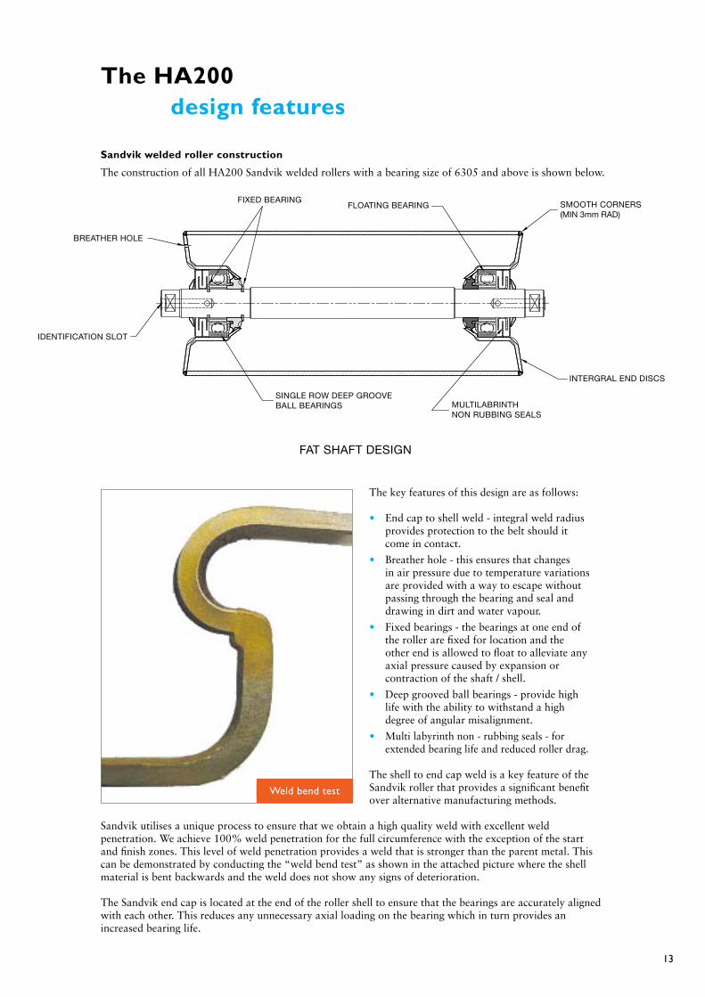
The HA200 design features
Sandvik welded roller construction
The construction of all HA200 Sandvik welded rollers with a bearing size of 6305 and above is shown below.
The key features of this design are as follows:
• End cap to shell weld - integral weld radius provides protection to the belt should it come in contact.
• Breather hole - this ensures that changes in air pressure due to temperature variations are provided with a way to escape without passing through the bearing and seal and drawing in dirt and water vapour.
• Fixed bearings - the bearings at one end of the roller are fixed for location and the other end is allowed to float to alleviate any axial pressure caused by expansion or contraction of the shaft / shell.
• Deep grooved ball bearings - provide high life with the ability to withstand a high degree of angular misalignment.
• Multi labyrinth non - rubbing seals - for extended bearing life and reduced roller drag.
The shell to end cap weld is a key feature of the Sandvik roller that provides a significant benefit over alternative manufacturing methods.
Sandvik utilises a unique process to ensure that we obtain a high quality weld with excellent weld penetration. We achieve 100% weld penetration for the full circumference with the exception of the start and finish zones. This level of weld penetration provides a weld that is stronger than the parent metal. This can be demonstrated by conducting the “weld bend test” as shown in the attached picture where the shell material is bent backwards and the weld does not show any signs of deterioration.
The Sandvik end cap is located at the end of the roller shell to ensure that the bearings are accurately aligned with each other. This reduces any unnecessary axial loading on the bearing which in turn provides an increased bearing life.
FIXED BEARINGFLOATING BEARING
BREATHER HOLE
IDENTIFICATION SLOT
SMOOTH CORNERS(MIN 3mm RAD)
INTERGRAL END DISCS
MULTILABRINTHNON RUBBING SEALS
SINGLE ROW DEEP GROOVEBALL BEARINGS
FAT SHAFT DESIGN
Weld bend test

14
Parallel roller bearing
The engineering concept
Any conveyor idler roller requires a bearing and shaft assembly to operate under deflection conditions. The relatively thin shaft is supported only at its extremities. It must accept the load from the shell through the bearings located 40 mm to 75 mm in from each end. This results in shaft bending and angular deflection at the bearings.
Sandvik rollers are engineered to satisfy this simple requirement. Bearings must accept angular deflection within specified limits and shafts must be sized so limits are not exceeded.
There is a wide bearing selection to choose from: parallel roller bearings, taper roller bearings or single row deep groove precision ball bearings. Parallel and taper roller bearings will tolerate 2 to 5 minutes of angular deflection, while single row deep groove precision ball bearings with C3 C4 clearances allow 12 to 16 minutes. All roller bearings have a grease pumping action which throws lubricant away from the roller track where it is required while ball bearings churn the grease, but retain it within the ball track area.
Sandvik chose single row deep groove precision ball bearings because they:
• Satisfy deflection criteria without unreasonable increases in shaft diameters between the bearings.• Adequately accept the axial thrust component of the load generated by conveyor belt movement across the roller face or where rollers are inclined in wing positions.• Permit practical shaft diameters which satisfy bearing deflection criteria and allow manufacturers normal dynamic capacity ratings to assess B10 bearing life.• Retain grease at the bearing faces permitting an extended period of operation without relubrication.• Have much lower friction or “drag” resistance, thus minimizing the power required to drive the rollers.• If the angular deflection limits are exceeded, the effect on ball bearings is less critical than for roller bearings.• Are readily available in commercial quantities at a competitive cost.
EDGE CONTACT
EDGE CONTACT
EDGE CONTACT
EDGE CONTACT
NORMAL CONTACTEDGE CONTACT
EDGE CONTACT
EDGE CONTACT
EDGE CONTACT
NORMAL CONTACT
EDGE CONTACT
EDGE CONTACT
EDGE CONTACT
EDGE CONTACT
NORMAL CONTACT
Ball bearing
Taper roller bearing

15
BEARINg PROTECTION— THE SANDVIK ULTIMATE SEAL
The greatest cause of idler bearing failure is lubricant contamination by grit and moisture. Pressure variations within normal idler rollers cause gritty and moist air to flow through the seal assemblies and into the bearings. This results in contamination, oxidation and emulsification of the bearing lubricant.
To overcome these problems, Sandvik HA200 idlers are designed with the following features:
• A breather hole to prevent cyclic pumping of air through the bearing and seal assembly (6305 bearings and above).
• Bearings are sealed by a grease filled, multi-labyrinth, seal assembly providing a long life seal. This arrangement minimizes the area where grit can enter and provides a long life seal.
• The inner side of each bearing is protected by an additional labyrinth seal assembly.
• An additional external neoprene seal provides protection at the entry point to the outer seal. The Sandvik HA200 Ultimate Seal Assembly has been tried and proven under the most stringent conditions for more than 40 years.
LubricationFor minimum rolling resistance, all fully assembled HA200 rollers are checked for rub-free shaft rotation. Even in the smallest rollers, the seal design provides an adequate grease reserve at the bearing for the life of the roller. Rollers are test run at an equivalent belt speed of 9 m/sec. to relieve grease pressure and identify any serious “out of balance” or run out. After test running, grease ways are plugged off, and no field regreasing is necessary.
Rotation ResistanceSandvik bearing and shaft selection and proven seal assembly ensure there are no rubbing parts within the roller. The only contact between shell and shaft is through the balls in the bearing. A high level of quality control is applied to all manufacturing processes so that bearing misalignment does not exceed 2 minutes, leaving 10 minutes for full load conditions. This is well within the bearing supplier’s specified deflection limits thereby ensuring that the only resistance factor is the very small torque necessary to shear the grease and ovecome bearing friction. This is important on any conveyor, but particularly in long, high-speed systems where power to rotate the rollers is significant.
Sandvik idlers are designed on sound engineering principles with particular attention to high balance, low vibration, long life, minimal maintenance and low resistance to rotation. The high performance of Sandvik idlers has been a benefit to field operations around the world.
16
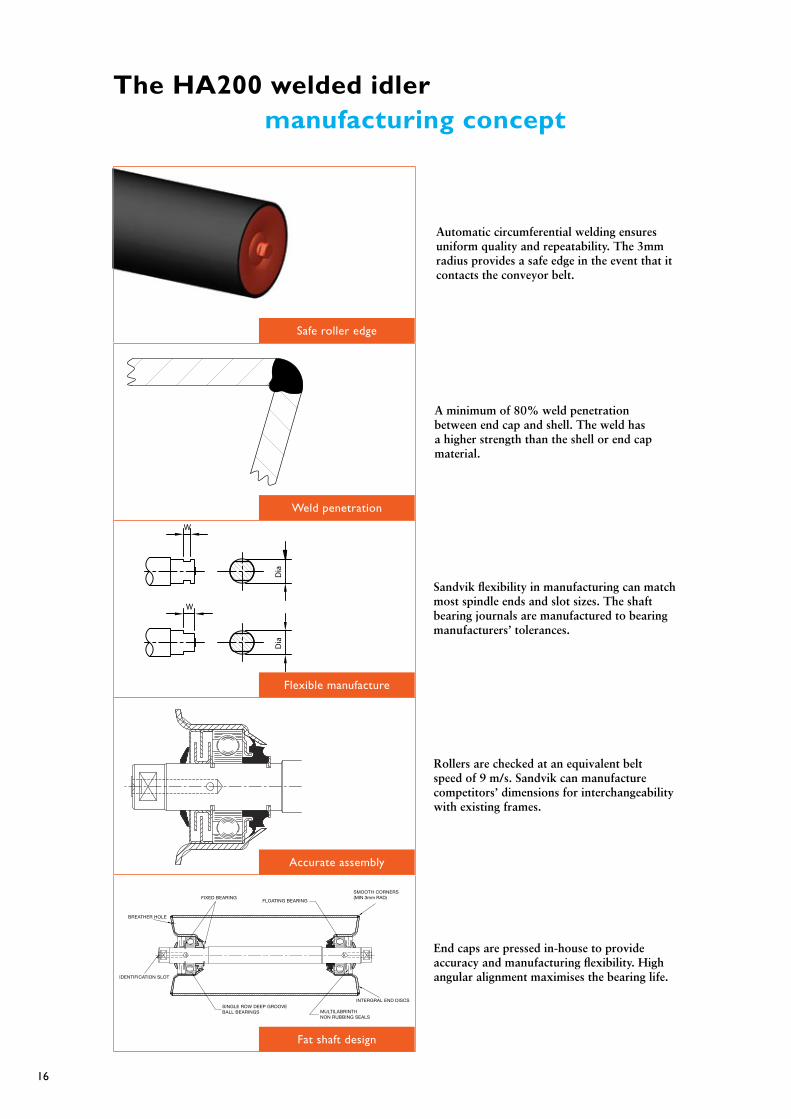
The HA200 welded idler manufacturing concept
FIXED BEARINGFLOATING BEARING
BREATHER HOLE
IDENTIFICATION SLOT
SMOOTH CORNERS(MIN 3mm RAD)
INTERGRAL END DISCS
MULTILABRINTHNON RUBBING SEALS
SINGLE ROW DEEP GROOVEBALL BEARINGS
Dia
Dia
W
W
Automatic circumferential welding ensures uniform quality and repeatability. The 3mm radius provides a safe edge in the event that it contacts the conveyor belt.
Sandvik flexibility in manufacturing can match most spindle ends and slot sizes. The shaft bearing journals are manufactured to bearing manufacturers’ tolerances.
A minimum of 80% weld penetration between end cap and shell. The weld has a higher strength than the shell or end cap material.
Rollers are checked at an equivalent belt speed of 9 m/s. Sandvik can manufacture competitors’ dimensions for interchangeability with existing frames.
End caps are pressed in-house to provide accuracy and manufacturing flexibility. High angular alignment maximises the bearing life.
Safe roller edge
Weld penetration
Flexible manufacture
Accurate assembly
Fat shaft design

17
Quality in action
Sandvik are renowned for manufacturing quality products that meet the most demanding of applications.
Quality is achieved by ensuring all stages of the design and manufacturing process are suitably measured and controlled.
Sandvik has ISO9002 accreditation for the manufacture of all HA200 conveyor idlers. This quality control captures all elements required to manufacture a quality product including:
• Component Design• Raw material procurement.• Manufacturing processes• Product testing and control
When you purchase an HA200 idler you are assured of the highest quality product that will perform to the highest of expectations.
Sandvik are the market leaders in the manufacture of conveyor components. Our manufacturing process and associated inspections and checks ensures that every Sandvik conveyor idler will provide years of trouble free service in the most demanding of applications.
Project specific Inspection and Test plans and Quality plans can be provided on request.

18
HA200 standards and tolerances
Unless otherwise agreed upon, Sandvik HA200 idlers will be supplied to Sandvik standard PS02.
These standards have been developed over 50 years of research and experience with conveyor design. The resulting product is technically and commercially sound, and is designed to virtually eliminate the need for maintenance.
LubricationAll bearing and seal chambers are completely shop filled with lithium based grease, specially formulated to minimize roller drag and give maximum resistance to water washout, etc. This grease is ideally suited for operating temperatures in the range of -10°C to +65°C.
For low temperature our rollers can be fitted with alternative greases; please contact Sandvik for further details.
Shop greasing is carried out which ensures that the bearings and all labyrinths are completely grease filled at initial greasing. Rollers manufactured by Sandvik are test run at an equivalent belt speed of 9 m/sec. for an average of two minutes in order to relieve grease pressure and check for obvious defects.
Breather HoleAll HA200 steel shell idler rollers,with a bearing of 6305 or above, will incorporate the Sandvik breather hole.
SURfACE TREATMENT
Conveyor RollersAfter assembly, each roller is cleaned to remove excess grease, etc., roller ends are spray painted with one coat of high gloss anti-corrosive enamel. Colour is Sandvik Orange.
Roller BasesAfter welding, roller bases are either –
a) grit blast cleaned prior to the application of one coat of high gloss anti-corrosive enamel.b) grit blast cleaned prior to hot dip galvanizing.
DIMENSIONAL TOLERANCES
1. Clearance between shaft and outer seal member: 0.15 to 0.20mm
2. Roller corner radius: 3mm minimum
3. Corner weld penetration: 80% minimum
4. Total Indicator Reading (T.I.R.) Run out max. Over steel shell:
Up to 750mm long 0.65mm
750-2200mm long .000867 x length mm
For all weigh rollers: 0.25mm
Low noise rollers: up to 950mm face 0.10mm

19
5. general Fabrication Tolerances a. Nominal O.D. of roller — steel shell: ±0.3mm
— rubber disc: ±0.8mm
b. Thickness of steel shell: ±0.5mm
c. Roller face length: ±1.5mm
d. Center roller height above base line: ±2.0mm
e. Transverse hole centers: ±2.0mm
f. Longitudinal hole centers: ±2.0mm
g. Return bracket drop height: ±2.0mm
h. Trough angle: NOTE: In addition to the ±1° fabrication tolerance a further +/- 1° ±1° must be allowed for standardised components
i. Weigher idler profile: Within 0.5mm of template
The elimination of any concept or feature could render the balance of the design invalid. Alterations and changes to these standards may involve additional costs or delays in supply.
Packaging Conveyor Rollers:
All conveyor rollers are packed on timber pallets and securely banded together to minimize shipping damage. These pallets simplify road, rail, and sea transport.
Roller Bases:
Bases are separately packed on timber pallets and securely strapped.
Assembly
Assembly of rollers into the bases is carried out by simply hand pressing the roller shaft ends into the base receiving slot.

20
Recommended location Head & Tail Pulleys
It is critical that the transition lengths between the pulley and the fully troughed idlers are of sufficient length to prevent damage to the conveyor belt or components.
If the transition length is too short then this will result in excess tensions in the conveyor belt edges which can cause the following problems:
• Splice failure – at belt edges.• Premature roller failure due to high deviation loads on the wing rollers.• Excessive and accelerated pulley lagging wear.
The level of stress induced at the belt edges is dependent on a number of factors being:
• The transition length.• The vertical distance the belt edges raises or lowers in the transition.• The idler trough angle.• The elastic modulus of the belt at the edges under tension.• The induced belt edge stress in the transition.
The location of the belt line in relation with the top of the pulley therefore has a significant effect on the transition length required.
It is common practice to locate the head or discharge pulleys at ½ of the trough depth to minimise the stresses induced in the belt and on the wing rollers. In the case of tail pulleys the full trough depth is often used to avoid an unloaded belt from being lifted up into the skirts which can result in mechanical damage.
Transition length Transition length
H
Head or high tension pulley Tail or low tension pulley

21
The following tables detail the distance from the belt line to the top of the pulley (H) to achieve a ½ trough depth.
Values of H for 1/2 Trough Depth (mm)
3 Roll Trough 5 Roll Trough
Trough Angle 30° 35° 45° 45° 55°
Belt Width
350 29 33 41
400 33 38 47
450 38 43 53
500 42 48 59
600 50 57 71
650 54 62 77
750 63 72 88
800 67 76 94
900 75 86 106
1000 83 96 118
1050 88 100 124
1200 100 115 141 131 154
1350 113 129 159 147 173
1400 117 134 165 153 179
1500 125 143 177 163 192
1600 133 153 189 174 205
1800 150 172 212 196 231
2000 167 191 236 218 256
2200 183 210 259 240 282
2500 208 239 295 272 320
3000 250 287 354 327 384
3500 292 335 412 381 448
H
Top face of head pulley
------------ -- --------- -- ----------
H
Top face of head pulley
------------ -- --------- -- ----------

22
It is recommended that transition lengths are obtained directly from the belt manufacture or from an appropriate standard such as IOS5293 Conveyor Belts – Determination of minimum transition distance on three idler rollers.
Alternatively the following tables can be used as a guide.
Half Trough depth - recommended minimum transition distances
Recommended Transition Distance
Distance = Factor x Belt Width
Idler Trough Angle % Rated Belt Tension Fabric Belts Steel Cord Belts
> 90% 1.4 3.2
30 60% to 90% 1.1 2.4
< 60% 0.8 1.6
> 90% 1.6 3.4
35 60% to 90% 1.3 2.6
< 60% 1.0 1.8
> 90% 2.0 4.0
45 60% to 90% 1.6 3.2
< 60% 1.3 2.3
full Trough depth - recommended minimum transition distances
Recommended Transition Distance
Distance = Factor x Belt Width
Idler Trough Angle % Rated Belt Tension Fabric Belts Steel Cord Belts
> 90% 3.0 6.6
30 60% to 90% 2.2 5.0
< 60% 1.6 3.4
> 90% 3.2 6.8
35 60% to 90% 2.4 5.2
< 60% 1.8 3.6
> 90% 4.0 8.0
45 60% to 90% 3.2 6.4
< 60% 2.4 4.4
Recommended Idler arrangement at Tail Loading Locations
Transition idlers should have plain or rubber covered wing rollers to minimise damage to the belt edge.
Transition Length
Transition LengthClose Spaced Standard Idlers Impact Zone
Normal Spaced Idlers
Transition Idler
Transition LengthH

23
(1) Misplaced or twisted components in the conveyor structure.(2) Driving and idler pulleys not normal to the conveyor centreline and not parallel with each other.(3) Carrying and return idlers not set normal to the conveyor belt centreline. (This point is very important for reversible belt conveyors).(4) Out-of-round or ‘stiff’ idler rollers giving belt contact forces asymmetrical to the belt centreline.(5) Poor belt splicing giving a transverse bent to the belt centreline at the splice.(6) Poor belt with excessive ‘weave’ of the belt centreline of asymmetrically tensioned cords/ fabric introduced during manufacture or due to incorrect storage.(7) Asymmetrical loading of burden.(8) Pulley diameters not symmetrical about centreline of belt.(9) Build-up of material on pulleys, idlers, and/or belt.(10) Side winds.(11) Transverse forces applied to belt by such items as angled belt scrapers.(12) Excessive tensioning of belt which is precluding all idlers from assisting in belt ‘steering’.(13) Under-tensioning of belt which precludes pulleys from controlling drift.(14) One side of the conveyor belt is operating wet, giving frictional resistance asymmetrically about the belt centreline. (Especially a problem if idlers have“lead”.)(15) Belt take-ups not taking up slack effectively during running and acceleration.(16) Belt take-ups not travelling in line with the belt centreline.
(17) Belt take-ups giving different forces on opposite sides of the belt. This can occur during take-up motion and is prevalent with hydraulic take-ups.(18) The belt is hotter on one side than the other, giving a variation in length between sides. This may be caused by situations such as the belt being shaded from the sun on one side or running near a furnace on one side.(19) Jammed idlers or extraneous jammed articles along the conveyor.(20) Too stiff a belt carcass or too steep a trough angle causes the belt to ride on the edges, thus avoiding steering influences of the idlers. Similar effects can be experienced by a deformed cross section of the belt carcass occurring after some use.(21) Structural/mechanical vibration emanating from any source, producing transverse loads on belt.(22) Excessive transverse clearance for take-up carriages.(23) Pulley faces worn concave.
The above list may be causing the following:
(1) Belt runs to one side along the conveyor.(2) Belts runs-off at head and tail pulley.(3) One section of belt runs to one side of the conveyor.(4) Belt runs to one side throughout its entire length at a specific location.(5) Belt flaps or makes excessive noise.
Once the conveyor has been checked and everything has been installed correctly and the system is square, if there is still a problem occurring please contact Sandvik for further advice.
The use of trough and return training idlers can overcome some of these problems listed above.
Belt tracking notes
When belt conveyors are installed within accepted conventional alignment limits with idlers and pulleys parallel, belt spliced square and true, and material loaded centrally, the belt will track correctly without the need for special training or tracking devices.
In practice, these ideal conditions are seldom achieved and corrective devices and accessories are required to maintain satisfactory training.
Sandvik has developed a range of training idlers, side guide rollers and an alignment instrument to overcome these tracking difficulties.
Side guide rollers may sometimes be used to restrain a belt from transverse displacement. They are normally employed in unusual circumstances as continuous roller contact with the edge of the belt may cause damage to the belt and seriously reduce its life.
The Sandvik Conveyliner Conveyor Alignment instrument overcomes many of the difficulties in setting idlers and pulleys normal to the belt line and may be used for re-alignment with the belt in position, should this be necessary. Please contact your local Sandvik representative for further details.
A number of the more common causes of poor belt tracking are set out below. Corrective action necessary for each of these is readily ascertained when the particular cause (or causes) is identified. Should further information be required on any of the Sandvik corrective devices, please contact your nearest Sandvik office.
24
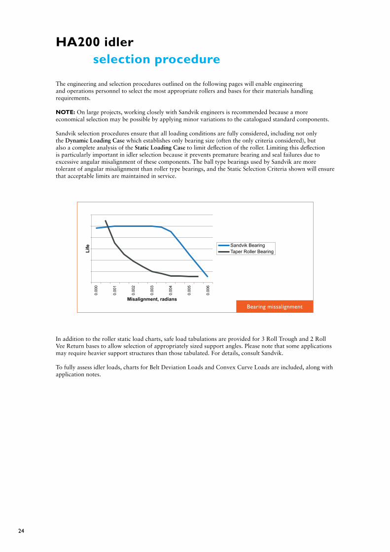
HA200 idler selection procedure
The engineering and selection procedures outlined on the following pages will enable engineering and operations personnel to select the most appropriate rollers and bases for their materials handling requirements.
NOTE: On large projects, working closely with Sandvik engineers is recommended because a more economical selection may be possible by applying minor variations to the catalogued standard components.
Sandvik selection procedures ensure that all loading conditions are fully considered, including not only the Dynamic Loading Case which establishes only bearing size (often the only criteria considered), but also a complete analysis of the Static Loading Case to limit deflection of the roller. Limiting this deflection is particularly important in idler selection because it prevents premature bearing and seal failures due to excessive angular misalignment of these components. The ball type bearings used by Sandvik are more tolerant of angular misalignment than roller type bearings, and the Static Selection Criteria shown will ensure that acceptable limits are maintained in service.
In addition to the roller static load charts, safe load tabulations are provided for 3 Roll Trough and 2 Roll Vee Return bases to allow selection of appropriately sized support angles. Please note that some applications may require heavier support structures than those tabulated. For details, consult Sandvik.
To fully assess idler loads, charts for Belt Deviation Loads and Convex Curve Loads are included, along with application notes.
Bearing missalignment
25
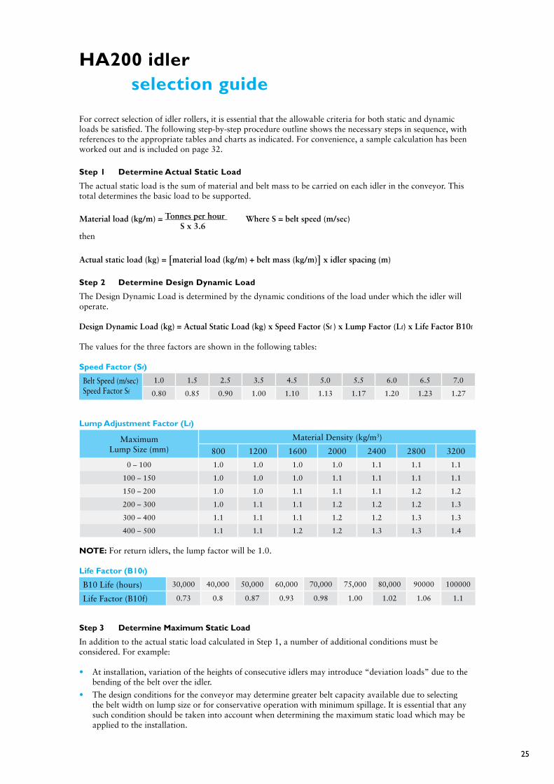
HA200 idler selection guide
For correct selection of idler rollers, it is essential that the allowable criteria for both static and dynamic loads be satisfied. The following step-by-step procedure outline shows the necessary steps in sequence, with references to the appropriate tables and charts as indicated. For convenience, a sample calculation has been worked out and is included on page 32.
Step 1 Determine Actual Static Load
The actual static load is the sum of material and belt mass to be carried on each idler in the conveyor. This total determines the basic load to be supported.
Material load (kg/m) = Tonnes per hour Where S = belt speed (m/sec) S x 3.6then
Actual static load (kg) = [material load (kg/m) + belt mass (kg/m)] x idler spacing (m)
Step 2 Determine Design Dynamic Load
The Design Dynamic Load is determined by the dynamic conditions of the load under which the idler will operate.
Design Dynamic Load (kg) = Actual Static Load (kg) x Speed Factor (Sf ) x Lump Factor (Lf) x Life Factor B10f
The values for the three factors are shown in the following tables:
Speed factor (Sf)
Belt Speed (m/sec) Speed Factor Sf
1.0 1.5 2.5 3.5 4.5 5.0 5.5 6.0 6.5 7.0
0.80 0.85 0.90 1.00 1.10 1.13 1.17 1.20 1.23 1.27
Lump Adjustment factor (Lf)
MaximumLump Size (mm)
Material Density (kg/m3)
800 1200 1600 2000 2400 2800 3200
0 – 100 1.0 1.0 1.0 1.0 1.1 1.1 1.1
100 – 150 1.0 1.0 1.0 1.1 1.1 1.1 1.1
150 – 200 1.0 1.0 1.1 1.1 1.1 1.2 1.2
200 – 300 1.0 1.1 1.1 1.2 1.2 1.2 1.3
300 – 400 1.1 1.1 1.1 1.2 1.2 1.3 1.3
400 – 500 1.1 1.1 1.2 1.2 1.3 1.3 1.4
NOTE: For return idlers, the lump factor will be 1.0.
Life factor (B10f)
B10 Life (hours) 30,000 40,000 50,000 60,000 70,000 75,000 80,000 90000 100000
Life Factor (B10f) 0.73 0.8 0.87 0.93 0.98 1.00 1.02 1.06 1.1
Step 3 Determine Maximum Static Load
In addition to the actual static load calculated in Step 1, a number of additional conditions must be considered. For example:
• At installation, variation of the heights of consecutive idlers may introduce “deviation loads” due to the bending of the belt over the idler.
• The design conditions for the conveyor may determine greater belt capacity available due to selecting the belt width on lump size or for conservative operation with minimum spillage. It is essential that any such condition should be taken into account when determining the maximum static load which may be applied to the installation.

26
• For deviation loads — which are more significant in longer, higher tension conveyors — procedure is on page 27. From these, you can calculate your additional load.
To determine a normal “full belt” condition which may exceed the design load, the following procedure should be followed:
Idler full belt load (kg) = [cross sectional area (m3) x material density (kg/m2) + belt mass (kg/m)] x idler spacing (m)
Tables for material density are shown on pages 47 to 50. These tables show the “surcharge angle”— the tangential angle formed by the material at the point of contact with the conveyor belt. Utilizing the correct surcharge angle for the material, the cross-sectional area of the belt for the trough idlers at 20, 30, 35 or 45 degrees trough angle can be readily determined from the tables on pages 52 to 56. The maximum static load condition may include one or both of the above, and should be evaluated as the sum of the loads applicable as follows:
Maximum Static Load (kg) = Full Belt Load + Deviation Load
Step 4 Selecting Roller Series
• Using the dynamic load assessed in Step 2 and the appropriate relative “roller set” Dynamic Load Charts located on pages 35 to 40, project the belt width required from the left-hand column across to the roller series column selected above. Select the roller series above this point of intersection.• Using the relative “roller set” Static Load Charts on pages 34 to 43, project the belt width required from the left-hand column across to the roller series column selected above. Using the actual static load as calculated in Step 1 above and the maximum static load as calculated in Step 3 above proceed as follows: 1. If the tabulated load exceeds both calculated static loads, selection is valid. 2. If the tabulated load exceeds the actual static load, but is less than the maximum static load, determine the cause.
a. If it is due to deviation loads, reconsider the out-of-level component. If this cannot be reviewed, select a heavier series roller to satisfy the requirement. b. If it is due to the maximum “full belt” load condition, consider the possibility (and frequency) of this condition ever occurring. If it appears possible, then select a heavier series roller from the static load chart to satisfy the requirement.
In the event that the idler type is not shown or the load exceeds the tables please contact Sandvik as a special design may be appropriate
Step 5 Select Base Angle Size
Using the maximum static load calculated in Step 1 above, and the appropriate static load chart for the base type concerned, that are located on pages 40 to 45, it is possible to determine the correct base member size. The column heading for this load indicates the support angle size required. All loads tabulated for the base angle members nominated are safe working loads. For details of momentary loadings which can be tolerated, consult Sandvik.
In the event that the idler type is not shown or the load exceeds the tables please contact Sandvik as a special design may be appropriate
Step 6 Considering Idlers under additional load conditions
Convex CurveFor idlers in a convex curve position, additional loading must be considered. On page 27 you will find a procedure to calculate the dynamic and static load conditions which can be related to the idler series selected in Step 3 and Step 4. Adjustment in spacing or use of a heavier series idler in this area can be readily evaluated.
Pick-up IdlersFor the “pick-up” idler used on a belt pick-up station, e.g., tripper assembly, the load on the idler can be readily calculated (see page 28). In this situation it is common practice to require a much heavier series idler.
NOTE:In some cases the loads determined above may exceed the normal idler ratings indicated in this catalogue. In these cases consult Sandvik for alternative heavy-duty designs.
27
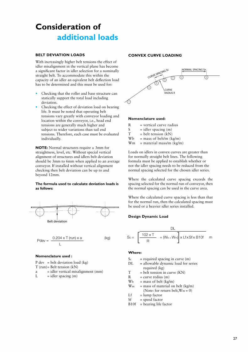
Consideration of additional loads
BELT DEVIATION LOADS
With increasingly higher belt tensions the effect of idler misalignment in the vertical plane has become a significant factor in idler selection for a nominally straight belt. To accommodate this within the capacity of an idler an eqivalent belt deflection load has to be determined and this must be used for:
• Checking that the roller and base structure can statically support the total load including deviation.• Checking the effect of deviation load on bearing life. It must be noted that operating belt tensions vary greatly with conveyor loading and location within the conveyor, i.e., head end tensions are generally much higher and subject to wider variations than tail end tensions. Therefore, each case must be evaluated individually.
NOTE: Normal structures require ± 3mm for straightness, level, etc. Without special vertical alignment of structures and idlers belt deviation should be 3mm to 6mm when applied to an average conveyor. If installed without vertical alignment checking then belt deviation can be up to and beyond 12mm.
The formula used to calculate deviation loads is as follows:
Nomenclature used :
P dev = belt deviation load (kg)T (run) = Belt tension (kN)a = idler vertical misalignment (mm)L = idler spacing (m)
CONVEx CURVE LOADINg
Nomenclature used:
R = vertical curve radiusS = idler spacing (m)T = belt tension (kN)Wb = mass of belt/m (kg/m)Wm = material mass/m (kg/m)
Loads on idlers in convex curves are greater than for normally straight belt lines. The following formula must be applied to establish whether or not the idler spacing needs to be reduced from the normal spacing selected for the chosen idler series.
Where the calculated curve spacing exceeds the spacing selected for the normal run of conveyor, then the normal spacing can be used in the curve area.
Where the calculated curve spacing is less than that for the normal run, then the calculated spacing must be used or a heavier idler series installed.
Design Dynamic Load
Where:
Sc = required spacing in curve (m)DL = allowable dynamic load for series required (kg)T = belt tension in curve (KN)R = curve redius (m)Wb = mass of belt (kg/m)Wm = mass of material on belt (kg/m) (Note: for return belt,Wm = 0) Lf = lump factorSf = speed factorB10f = bearing life factor
Pdev =0.204 x T (run) x a (kg)
L
Belt deviation
Sc =
DL
m102 x T
+ (Wb + Wm) x Lf x Sf x B10fR[ ]
CURVE SPACING Sc NORMAL SPACING Sn
CURVERADIUS R

28
Design Static LoadOnce the spacing has been finalized, it is advisable to check that the roller and base structure is capable of carrying the static load.
The actual static load is given by:
The maximum static load is given by:
These values must be less than those given in the relevant tables.
BELT PICK UP STATION LOADINg
The load on an idler used in a pick-up station is a special case of a belt deviation load and should be calculated as follows:
Actual Static Load is given by:
Where: Si2,Si1 = idler spacing (m) W = Wb + Wm (Mass of belt + Mass of material)(kg/m) T = belt tension (KN) Hp = pick-up hight (m)
Dynamic Load is given by:
Where: Sf = Speed factor Lf = Lump factor B10f = Bearing Life factor
Maximum Static Load is given by:
Where Wmax is the mass of belt and material per metre under “full belt” conditions, and Tmax is the maximum operation tension.
F8 = W (kg) [ ( ) ]Si2
+Si1
2
+T x Hp
2 2 4.9xW
Fd = W x Sf x L1 x B10f(kg) [ ( ) ]Si2
+Si1
2
+T x Hp
2 2 4.9xW
[ ( ) ]Fs max = W max (kg)
Si2+
Si12
+Tmax x Hp
2 2 4.9xWmax
LOAD ON IDLER USED IN A BELT PICKUP STATION
THIS IDLER SUPPORTSLARGER THAN NORMAL LOAD IMPACT/OR PICKUP TABLE
TOP OF MAIN CONVEYOR IDLERS
Si2
Hp
Si1
T
T
P = Sc X kg[ ]102 x T+ ( Wb + Wm )
R
Pmax = Sc X kg[ ]102 x T
+ ( Wb + Wm max)R
29
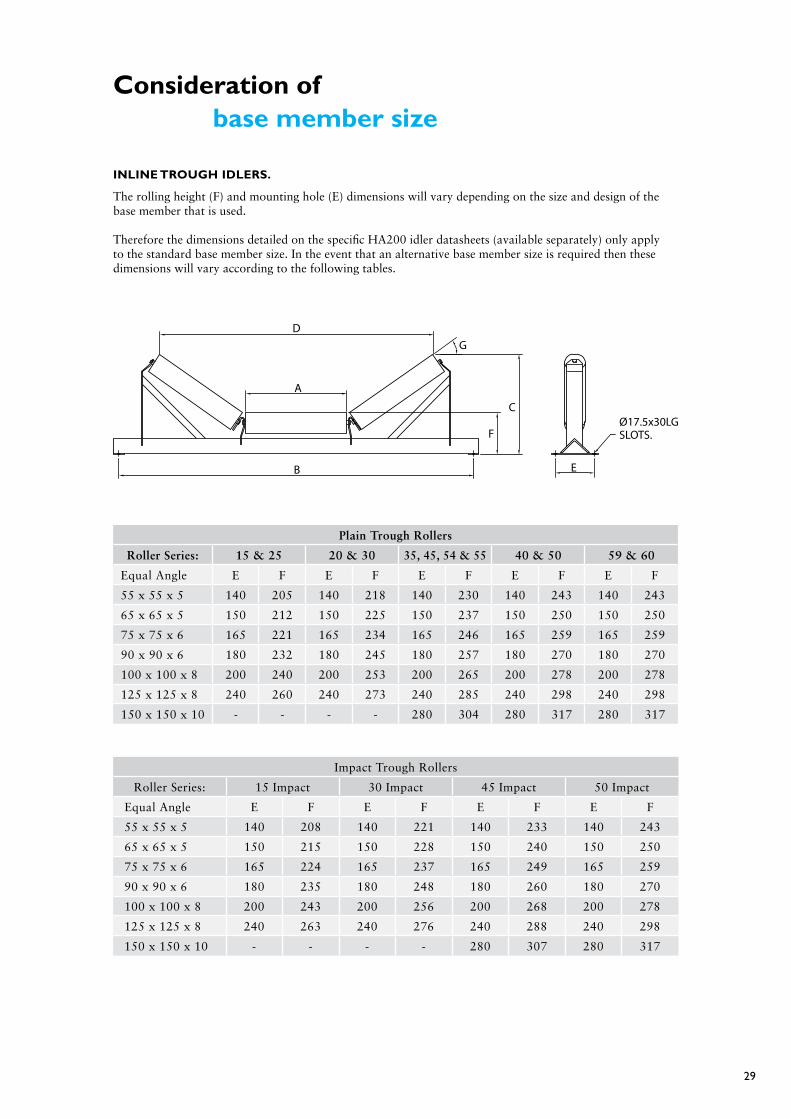
Consideration of base member size
INLINE TROUgH IDLERS.
The rolling height (F) and mounting hole (E) dimensions will vary depending on the size and design of the base member that is used.
Therefore the dimensions detailed on the specific HA200 idler datasheets (available separately) only apply to the standard base member size. In the event that an alternative base member size is required then these dimensions will vary according to the following tables.
Plain Trough Rollers
Roller Series: 15 & 25 20 & 30 35, 45, 54 & 55 40 & 50 59 & 60
Equal Angle E F E F E F E F E F
55 x 55 x 5 140 205 140 218 140 230 140 243 140 243
65 x 65 x 5 150 212 150 225 150 237 150 250 150 250
75 x 75 x 6 165 221 165 234 165 246 165 259 165 259
90 x 90 x 6 180 232 180 245 180 257 180 270 180 270
100 x 100 x 8 200 240 200 253 200 265 200 278 200 278
125 x 125 x 8 240 260 240 273 240 285 240 298 240 298
150 x 150 x 10 - - - - 280 304 280 317 280 317
Impact Trough Rollers
Roller Series: 15 Impact 30 Impact 45 Impact 50 Impact
Equal Angle E F E F E F E F
55 x 55 x 5 140 208 140 221 140 233 140 243
65 x 65 x 5 150 215 150 228 150 240 150 250
75 x 75 x 6 165 224 165 237 165 249 165 259
90 x 90 x 6 180 235 180 248 180 260 180 270
100 x 100 x 8 200 243 200 256 200 268 200 278
125 x 125 x 8 240 263 240 276 240 288 240 298
150 x 150 x 10 - - - - 280 307 280 317
B
A
D
E
SLOTS.Ø17.5x30LG
G
C
F

30
Notes on impact idler selection
The selection of impact idlers requires very careful consideration based on considerable experience, and the following points mustalways be taken into account:
The Lump Size
Particularly important in establishing lump size is the breaking characteristic of the run-of-mine or crushing properties of the material in question. Slabby material can produce long lumps with the longest dimension three to five times the stated lump size or larger. Most screens or grills allow lumps to pass through a rectangular opening, but the long dimension of the lump is unrestricted.
Material Density
The material density has a direct effect on the mass of any lump that impacts the idler.
Impact force
The impact force is a function of the square of the lump velocity at the point of impact, directly related to the vertical fall height.
Percentage of Lumps in Streams
If the amount of fines in a load stream is decreased—that is, the percentage of lumps is increased— the effect of lump mass and velocity is amplified. To illustrate this effect, consider a single lump arriving at the belt in the middle of a flow of fines. The surrounding fines form a bed underneath and around the lump, which dissipates energy by particle frictions, crushing, etc. Hence, the impact energy to be absorbed by the impact idler is reduced. A single lump which at times might constitute 100% of a load stream at a particular instant has no opportunity for its energy at impact to be dissipated.
Spacing of Idlers
The reason for using closely spaced idlers at a loading point is to maintain the belt position and shape to minimize spillage. The impact per idler is not necessarily reduced significantly with a greater number of idlers in the bed because the absorption of energy by belt deflection is minimized and loads are directly applied into the idler without this benefit.
Rigid Base or Suspended Idlers
To reduce impact forces a large movement is required at the point of application of the impact. Under certain conditions for heavy impacts the rigid base idler has to be so stiff that the base and roller reactions become unsatisfactorily high. The suspended idler, because of its flexibility, causes energy to be dissipated by means of link friction, belt friction, and reduces idler reactions significantly through the greater movement of the idler during impact.
Sandvik, using detailed in house software, has a procedure for assessing and selecting impact idlers as outlined on this page. We recommend that you consult Sandvik for a more detailed total assessment and recommendation for each impact idler situation. To enable full assessment it is necessary to know details of lump size, percentage lumps in material, fall height, transfer details, tonnes per hour and material density.
31
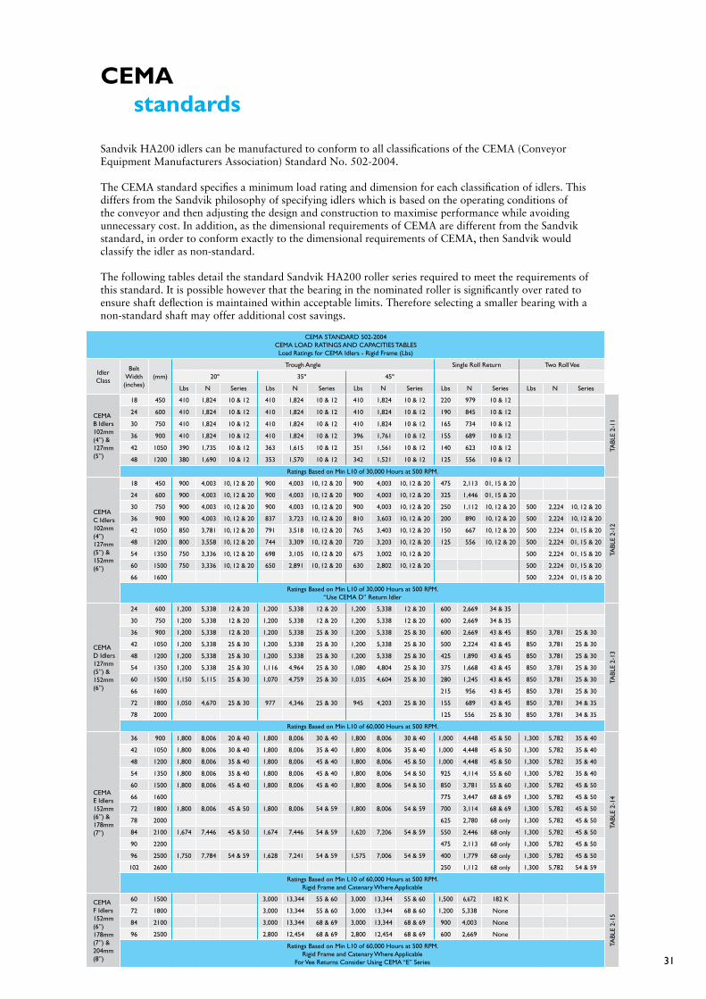
CEMA standards
Sandvik HA200 idlers can be manufactured to conform to all classifications of the CEMA (Conveyor Equipment Manufacturers Association) Standard No. 502-2004.
The CEMA standard specifies a minimum load rating and dimension for each classification of idlers. This differs from the Sandvik philosophy of specifying idlers which is based on the operating conditions of the conveyor and then adjusting the design and construction to maximise performance while avoiding unnecessary cost. In addition, as the dimensional requirements of CEMA are different from the Sandvik standard, in order to conform exactly to the dimensional requirements of CEMA, then Sandvik would classify the idler as non-standard.
The following tables detail the standard Sandvik HA200 roller series required to meet the requirements of this standard. It is possible however that the bearing in the nominated roller is significantly over rated to ensure shaft deflection is maintained within acceptable limits. Therefore selecting a smaller bearing with a non-standard shaft may offer additional cost savings.
CEMA STANDARD 502-2004CEMA LOAD RATINGS AND CAPACITIES TABLESLoad Ratings for CEMA Idlers - Rigid Frame (Lbs)
Idler Class
Belt Width
(inches)(mm)
Trough Angle Single Roll Return Two Roll Vee
20º 35º 45º
Lbs N Series Lbs N Series Lbs N Series Lbs N Series Lbs N Series
CEMA B Idlers 102mm (4”) & 127mm (5”)
18 450 410 1,824 10 & 12 410 1,824 10 & 12 410 1,824 10 & 12 220 979 10 & 12
TABL
E 2-
11
24 600 410 1,824 10 & 12 410 1,824 10 & 12 410 1,824 10 & 12 190 845 10 & 12
30 750 410 1,824 10 & 12 410 1,824 10 & 12 410 1,824 10 & 12 165 734 10 & 12
36 900 410 1,824 10 & 12 410 1,824 10 & 12 396 1,761 10 & 12 155 689 10 & 12
42 1050 390 1,735 10 & 12 363 1,615 10 & 12 351 1,561 10 & 12 140 623 10 & 12
48 1200 380 1,690 10 & 12 353 1,570 10 & 12 342 1,521 10 & 12 125 556 10 & 12
Ratings Based on Min L10 of 30,000 Hours at 500 RPM.
CEMA C Idlers 102mm (4”) 127mm (5”) & 152mm (6”)
18 450 900 4,003 10, 12 & 20 900 4,003 10, 12 & 20 900 4,003 10, 12 & 20 475 2,113 01, 15 & 20
TABL
E 2-
12
24 600 900 4,003 10, 12 & 20 900 4,003 10, 12 & 20 900 4,003 10, 12 & 20 325 1,446 01, 15 & 20
30 750 900 4,003 10, 12 & 20 900 4,003 10, 12 & 20 900 4,003 10, 12 & 20 250 1,112 10, 12 & 20 500 2,224 10, 12 & 20
36 900 900 4,003 10, 12 & 20 837 3,723 10, 12 & 20 810 3,603 10, 12 & 20 200 890 10, 12 & 20 500 2,224 10, 12 & 20
42 1050 850 3,781 10, 12 & 20 791 3,518 10, 12 & 20 765 3,403 10, 12 & 20 150 667 10, 12 & 20 500 2,224 01, 15 & 20
48 1200 800 3,558 10, 12 & 20 744 3,309 10, 12 & 20 720 3,203 10, 12 & 20 125 556 10, 12 & 20 500 2,224 01, 15 & 20
54 1350 750 3,336 10, 12 & 20 698 3,105 10, 12 & 20 675 3,002 10, 12 & 20 500 2,224 01, 15 & 20
60 1500 750 3,336 10, 12 & 20 650 2,891 10, 12 & 20 630 2,802 10, 12 & 20 500 2,224 01, 15 & 20
66 1600 500 2,224 01, 15 & 20
Ratings Based on Min L10 of 30,000 Hours at 500 RPM.“Use CEMA D” Return Idler
CEMA D Idlers 127mm (5”) & 152mm (6”)
24 600 1,200 5,338 12 & 20 1,200 5,338 12 & 20 1,200 5,338 12 & 20 600 2,669 34 & 35TA
BLE
2-13
30 750 1,200 5,338 12 & 20 1,200 5,338 12 & 20 1,200 5,338 12 & 20 600 2,669 34 & 35
36 900 1,200 5,338 12 & 20 1,200 5,338 25 & 30 1,200 5,338 25 & 30 600 2,669 43 & 45 850 3,781 25 & 30
42 1050 1,200 5,338 25 & 30 1,200 5,338 25 & 30 1,200 5,338 25 & 30 500 2,224 43 & 45 850 3,781 25 & 30
48 1200 1,200 5,338 25 & 30 1,200 5,338 25 & 30 1,200 5,338 25 & 30 425 1,890 43 & 45 850 3,781 25 & 30
54 1350 1,200 5,338 25 & 30 1,116 4,964 25 & 30 1,080 4,804 25 & 30 375 1,668 43 & 45 850 3,781 25 & 30
60 1500 1,150 5,115 25 & 30 1,070 4,759 25 & 30 1,035 4,604 25 & 30 280 1,245 43 & 45 850 3,781 25 & 30
66 1600 215 956 43 & 45 850 3,781 25 & 30
72 1800 1,050 4,670 25 & 30 977 4,346 25 & 30 945 4,203 25 & 30 155 689 43 & 45 850 3,781 34 & 35
78 2000 125 556 25 & 30 850 3,781 34 & 35
Ratings Based on Min L10 of 60,000 Hours at 500 RPM.
CEMA E Idlers 152mm (6”) & 178mm (7”)
36 900 1,800 8,006 20 & 40 1,800 8,006 30 & 40 1,800 8,006 30 & 40 1,000 4,448 45 & 50 1,300 5,782 35 & 40
TABL
E 2-
14
42 1050 1,800 8,006 30 & 40 1,800 8,006 35 & 40 1,800 8,006 35 & 40 1,000 4,448 45 & 50 1,300 5,782 35 & 40
48 1200 1,800 8,006 35 & 40 1,800 8,006 45 & 40 1,800 8,006 45 & 50 1,000 4,448 45 & 50 1,300 5,782 35 & 40
54 1350 1,800 8,006 35 & 40 1,800 8,006 45 & 40 1,800 8,006 54 & 50 925 4,114 55 & 60 1,300 5,782 35 & 40
60 1500 1,800 8,006 45 & 40 1,800 8,006 45 & 40 1,800 8,006 54 & 50 850 3,781 55 & 60 1,300 5,782 45 & 50
66 1600 775 3,447 68 & 69 1,300 5,782 45 & 50
72 1800 1,800 8,006 45 & 50 1,800 8,006 54 & 59 1,800 8,006 54 & 59 700 3,114 68 & 69 1,300 5,782 45 & 50
78 2000 625 2,780 68 only 1,300 5,782 45 & 50
84 2100 1,674 7,446 45 & 50 1,674 7,446 54 & 59 1,620 7,206 54 & 59 550 2,446 68 only 1,300 5,782 45 & 50
90 2200 475 2,113 68 only 1,300 5,782 45 & 50
96 2500 1,750 7,784 54 & 59 1,628 7,241 54 & 59 1,575 7,006 54 & 59 400 1,779 68 only 1,300 5,782 45 & 50
102 2600 250 1,112 68 only 1,300 5,782 54 & 59
Ratings Based on Min L10 of 60,000 Hours at 500 RPM.Rigid Frame and Catenary Where Applicable
CEMA F Idlers 152mm (6”) 178mm (7”) & 204mm (8”)
60 1500 3,000 13,344 55 & 60 3,000 13,344 55 & 60 1,500 6,672 182 K
TABL
E 2-
15
72 1800 3,000 13,344 55 & 60 3,000 13,344 68 & 60 1,200 5,338 None
84 2100 3,000 13,344 68 & 69 3,000 13,344 68 & 69 900 4,003 None
96 2500 2,800 12,454 68 & 69 2,800 12,454 68 & 69 600 2,669 None
Ratings Based on Min L10 of 60,000 Hours at 500 RPM.Rigid Frame and Catenary Where Applicable
For Vee Returns Consider Using CEMA “E” Series
32
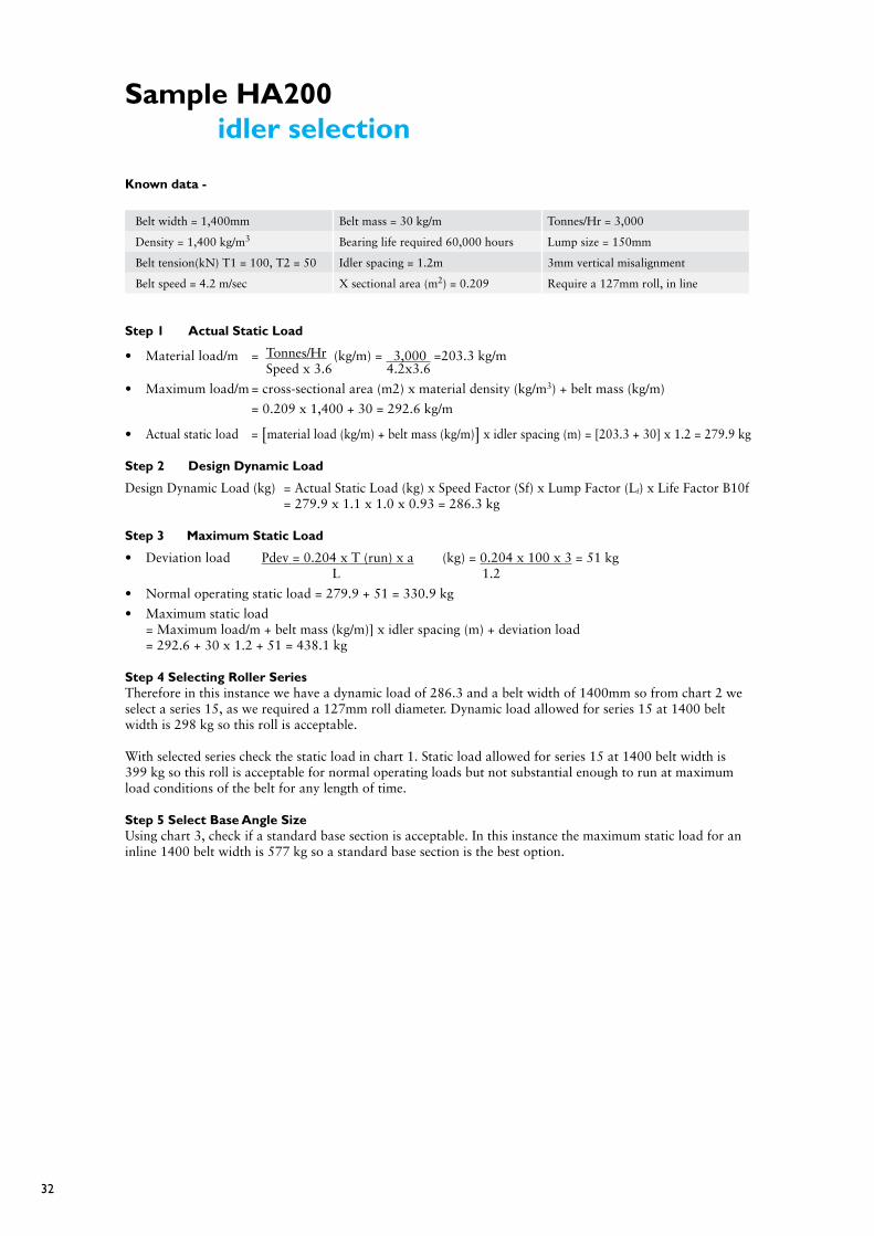
Sample HA200 idler selection
Known data -
Belt width = 1,400mm Belt mass = 30 kg/m Tonnes/Hr = 3,000
Density = 1,400 kg/m3 Bearing life required 60,000 hours Lump size = 150mm
Belt tension(kN) T1 = 100, T2 = 50 Idler spacing = 1.2m 3mm vertical misalignment
Belt speed = 4.2 m/sec X sectional area (m2) = 0.209 Require a 127mm roll, in line
Step 1 Actual Static Load
• Materialload/m = Tonnes/Hr (kg/m) = 3,000 =203.3 kg/m Speed x 3.6 4.2x3.6
• Maximumload/m=cross-sectionalarea(m2)xmaterialdensity(kg/m3) + belt mass (kg/m)
= 0.209 x 1,400 + 30 = 292.6 kg/m
• Actual static load = [material load (kg/m) + belt mass (kg/m)] x idler spacing (m) = [203.3 + 30] x 1.2 = 279.9 kg
Step 2 Design Dynamic Load
Design Dynamic Load (kg) = Actual Static Load (kg) x Speed Factor (Sf) x Lump Factor (Lf) x Life Factor B10f = 279.9 x 1.1 x 1.0 x 0.93 = 286.3 kg
Step 3 Maximum Static Load
• Deviationload Pdev = 0.204 x T (run) x a (kg) = 0.204 x 100 x 3 = 51 kg L 1.2
• Normaloperatingstaticload=279.9+51=330.9kg
• Maximumstaticload = Maximum load/m + belt mass (kg/m)] x idler spacing (m) + deviation load = 292.6 + 30 x 1.2 + 51 = 438.1 kg
Step 4 Selecting Roller SeriesTherefore in this instance we have a dynamic load of 286.3 and a belt width of 1400mm so from chart 2 we select a series 15, as we required a 127mm roll diameter. Dynamic load allowed for series 15 at 1400 belt width is 298 kg so this roll is acceptable.
With selected series check the static load in chart 1. Static load allowed for series 15 at 1400 belt width is 399 kg so this roll is acceptable for normal operating loads but not substantial enough to run at maximum load conditions of the belt for any length of time.
Step 5 Select Base Angle SizeUsing chart 3, check if a standard base section is acceptable. In this instance the maximum static load for an inline 1400 belt width is 577 kg so a standard base section is the best option.
dsaucm
Text Box
With selected series check the maximum static load in chart 1. Maximum static load allowed for series 15 at 1400 belt width is 399 kg so this roll is not acceptable for normal operating loads. It is therefore necessary to select a series 25 roller for this application.
dsaucm
Text Box
322.6 kg/m
dsaucm
Text Box
= Maximum load/m x idler spacing (m) + deviation load = 292.6 x 1.2 + 51 = 438.1 kg
33
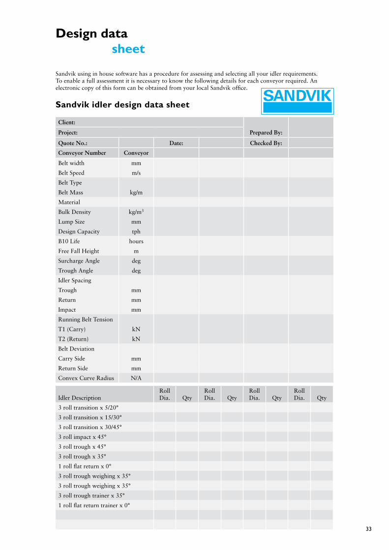
Design data sheet
Sandvik using in house software has a procedure for assessing and selecting all your idler requirements. To enable a full assessment it is necessary to know the following details for each conveyor required. An electronic copy of this form can be obtained from your local Sandvik office.
Sandvik idler design data sheet
Client:
Project: Prepared By:
Quote No.: Date: Checked By:
Conveyor Number Conveyor
Belt width mm
Belt Speed m/s
Belt Type
Belt Mass kg/m
Material
Bulk Density kg/m3
Lump Size mm
Design Capacity tph
B10 Life hours
Free Fall Height m
Surcharge Angle deg
Trough Angle deg
Idler Spacing
Trough mm
Return mm
Impact mm
Running Belt Tension
T1 (Carry) kN
T2 (Return) kN
Belt Deviation
Carry Side mm
Return Side mm
Convex Curve Radius N/A
Idler DescriptionRoll Dia. Qty
Roll Dia. Qty
Roll Dia. Qty
Roll Dia. Qty
3 roll transition x 5/20°
3 roll transition x 15/30°
3 roll transition x 30/45°
3 roll impact x 45°
3 roll trough x 45°
3 roll trough x 35°
1 roll flat return x 0°
3 roll trough weighing x 35°
3 roll trough weighing x 35°
3 roll trough trainer x 35°
1 roll flat return trainer x 0°

34
HA200 Idler load charts
Chart 1 3 Roll - 35° trough idlers Static Load Selection
3 Roll trough set (kg) (rollers Only) Select base from chart 3 on page 36.)
Beltwidth(mm)
Roller Series
01 05 10 11 12 15 20 25 30 35 45 50 54 55 59 60
350 250 248
400 266 264
450 281 279
500 295 374 293 373 387 387
600 321 407 320 406 421 421
650 335 424 334 423 425 439
750 358 453 356 360 359 468 745
800 368 466 336 335 335 482 752
900 390 494 290 289 411 511 648
1000 406 514 375 374 373 531 588 531 844 847
1050 420 531 345 344 343 545 541 549 776 876
1200 448 466 294 293 292 465 460 586 661 860 931 1678 933
1350 253 405 400 579 574 747 984 1460 986
1400 249 399 394 570 566 735 990 1438 992
1500 222 356 351 652 749 940 1036 1286 1038
1600 211 340 335 664 716 898 1054 1229 1056 1056 1644 2064
1800 632 626 785 1085 1075 1114 1114 1440 2150
2000 680 943 932 1178 1178 1666 1866
2200 592 824 811 1106 1242 1460 1630
2400 1290 1327 1481
2500 1308 1692
2600 1332 1219 1614
2800 1389 1090 1445
3000 1340 995 1323

35
Chart 2 3 Roll - 35° trough idlers Dynamic Load Selection
3 Roll trough set (kg) (Rollers Only) Select base from chart 3 on page 36.)
Beltwidth(mm)
Roller Series
01 05 10 11 12 15 20 25 30 35 45 50 54 55 59 60
350 282 256
400 282 256
450 282 256
500 282 292 256 265 274 302
600 282 292 255 264 274 302
650 281 291 255 264 273 302
750 281 291 255 264 273 301 317
800 281 291 255 264 273 301 317
900 281 290 254 263 272 301 316
1000 280 290 254 263 272 300 315 485 513 642
1050 280 290 254 263 272 300 315 485 512 642
1200 280 289 253 262 271 299 314 484 511 640 759 793 939
1350 253 299 313 484 510 639 757 791 937
1400 249 298 313 484 510 639 757 791 937
1500 222 298 312 483 509 638 756 789 936
1600 211 298 311 483 508 638 756 788 936 1207 978 1264
1800 482 507 637 755 786 935 1206 976 1261
2000 635 753 783 933 1204 973 1258
2200 592 751 780 931 1202 970 1256
2400 1201 968 1253
2500 1201 1252
2600 1200 966 1251
2800 1198 963 1248
3000 1197 960 1246

36
Chart 3 3 Roll-35° trough bases frame selection (kg)
3 roll 35° Offset base angle size (mm)
55*55*5< 65*65*5< 75*75*6< 90*90*6< 100*8< 125*8< 150*10< 200*13<
Bel
t W
idth
(m
m)
500 271
600 209
650 191 257
750 154 207
800 138 186 397
900 117 158 338
1000 133 283 434
1050 122 263 403
1200 209 324 794
1350 163 251 615
1400 153 235 577 733
1500 209 512 652
1600 406 516 1233
1800 339 431 1034
2000 362 872 1539
2200 313 752 1325
2400 642 1148
2500 603 1069
3 roll 35° Inline base angle size (mm)
55*55*5< 65*65*5< 75*75*6< 90*90*6< 100*8< 125*8< 150*10< 200*13<
Bel
t W
idth
(m
m)
500 271
600 209
650 191 257
750 154 207
800 138 186 397
900 117 158 338
1000 133 283 434
1050 122 263 403
1200 209 324 794
1350 163 251 615
1400 153 235 577 733
1500 209 512 652
1600 406 516 1233
1800 339 431 1034
2000 362 872 1539
2200 313 752 1325
2400 642 1148
2500 603 1069
Standard Non standard
For belt widths 2600 mm and greater, Sandvik recommends alternate base members to suit the application. Refer to Sandvik for details.

37
Chart 4 Single roll flat carry and return rollers Static Load Selection
flat return idlers (kg)
Beltwidth(mm)
Roller series
01 05 10 11 12 15 20 25 30 35 45 50 54 55 59 60
350 316 140
400 281 122
450 250 108
500 223 222 96 138 137 221
600 182 181 112 111 110 180
650 166 164 101 100 99 163
750 138 136 141 140 138 135 130
800 126 124 129 127 126 123 117
900 105 103 107 105 104 101 95
1000 86 84 89 86 85 82 134 201 194 251 667 1027
1050 78 130 80 78 76 128 121 185 178 232 827 965
1200 55 117 56 100 98 95 88 143 136 181 267 253 690 1326
1350 59 57 48 158 149 124 194 270 655 1069
1400 50 48 39 143 135 111 265 248 618 1012
1500 32 30 62 116 106 86 225 207 547 908
1600 28 17 64 53 154 152 131 683 341 1012 321
1800 59 48 85 152 129 529 244 805 408
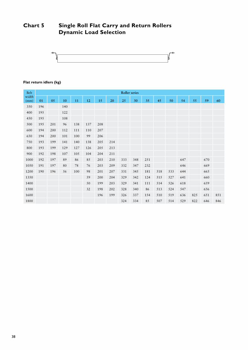
38
Chart 5 Single Roll flat Carry and Return Rollers Dynamic Load Selection
flat return idlers (kg)
Beltwidth(mm)
Roller series
01 05 10 11 12 15 20 25 30 35 45 50 54 55 59 60
350 196 140
400 195 122
450 195 108
500 195 201 96 138 137 208
600 194 200 112 111 110 207
650 194 200 101 100 99 206
750 193 199 141 140 138 205 214
800 193 199 129 127 126 205 213
900 192 198 107 105 104 204 211
1000 192 197 89 86 85 203 210 333 348 251 647 670
1050 191 197 80 78 76 203 209 332 347 232 646 669
1200 190 196 56 100 98 201 207 331 345 181 518 533 644 665
1350 59 200 204 329 342 124 515 527 641 660
1400 50 199 203 329 341 111 514 526 618 659
1500 32 198 202 328 340 86 513 524 547 656
1600 196 199 326 337 154 510 519 636 825 651 851
1800 324 334 85 507 514 529 822 646 846

39
Chart 6 2 Roll - 10° Vee Return Idlers Static Load Selection
2 Roll Vee return idler (kg) (Rollers Only) Select base from chart 8 below.
Beltwidth(mm)
Roller series
05 10 11 12 15 20 25 30 35 45 50 54 55 59
600 701 390 389 388 725
650 723 361 360 359 748
750 688 304 302 301 686 681
800 651 287 285 284 650 644
900 567 249 247 245 566 559
1000 499 217 215 213 498 491
1050 477 207 205 203 475 468
1200 398 248 246 244 396 388 569 561
1350 207 340 331 492 483
1400 200 329 320 476 468
1500 306 298 289 434 425
1600 279 272 261 397 388 511 1044 1025 1405 1804 1386
1800 336 504 640 900 879 1217 1816 1196
2000 543 772 748 1050 1576 1027
2200 465 668 642 917 1386 891
2400 397 803 1227 1070
2500 535 739 1138 987
2600 504 700 1084 937
2800 430 607 957 817
3000 360 520 840 979

40
Chart 7 2 Roll - 10° Vee return Rollers Dynamic Load Selection
2 Roll Vee return idler (kg) (Rollers Only) Select base from chart 8 below.
Beltwidth(mm)
Roller series
05 10 11 12 15 20 25 30 35 45 50 54 55 59
600 406 356 368 381 420
650 406 355 360 359 420
750 405 304 302 301 419 439
800 405 287 285 284 418 439
900 404 249 247 245 417 437
1000 403 217 215 213 417 436
1050 403 207 205 203 416 435
1200 401 248 246 244 415 433 674 708
1350 207 413 431 672 706
1400 200 413 430 672 706
1500 306 412 429 671 704
1600 279 411 427 670 703 511 1049 1088 1301 1680 1353
1800 668 700 640 1046 1083 1217 1677 1196
2000 543 1043 1078 1050 1674 1027
2200 465 1040 1073 917 1671 891
2400 397 803 1668 1070
2500 535 739 1666 987
2600 504 700 1665 937
2800 430 607 1662 817
3000 360 520 1659 979

41
Chart 8 2 Roll - 10° Vee Return Idlers frame Selection (kg)
2 roll 10’ V return rolls - base angle size (mm)
65*65*5< 75*75*6< 90*90*6< 100*8< 125*8< 150*10<
BE
LT W
IDT
H
600 311
650 297
750 268
800 255
900 215
1000 183
1050 170 362
1200 139 296
1350 115 245 376
1400 107 231 355 754
1500 204 316 703
1600 183 275 673 826
1800 224 571 724
2000 469 601 1275
2200 398 510 1213
2400 347 438 1060
2500 408 979
Standard Non standard

42
Research & development
Sandvik is committed to investing in research and development activities. As a global company we commit in excess of 4% of sales revenue into research and development activities. As a result of this commitment we have in excess of 2,200 people employed within R&D and have over 4,500 registered patents.
In the field of conveyor technology we have centers of excellence located in Australia, Finland, Germany, Austria, South Africa, Brazil and India. These facilities are committed to expanding our knowledge of conveyor systems in both the design and operation conditions. We are therefore striving to enhance our existing products as well as offer leading edge solutions to the market.
The industry is constantly seeking materials handling performance that can transport higher tonnages, at a lower total cost with more reliability. They also need to have a small carbon footprint, be environmentally responsible and offer the highest level of operator safety.
We have developed new material constructions and designs to allow rollers to run faster and with more load while reducing the noise levels and extending the service life.
Condition monitoring and other processes that are aimed at reducing the cost of ownership are continually being developed and introduced to the market.
Jackdown FEA
Minimised stress zones

43
Low noise roll development
Sandvik’s research and development team worked closely with a number of our key clients to develop a product that provides significant reductions in conveyor noise. These developments have delivered reductions in noise output of 18 dB(A) for the low noise roller. The attached chart demonstrates the significant reduction that this represents.
Change in Sound Levels (dB(A) Change in apparent loudness to the human ear
1 dB imperceptible (except for tones)
3 dB just barely perceptible
6 dB clearly noticeable
10 dB half as loud
20 dB one fourth as loud
It has been identified that the roller surface profile has a direct effect on the noise generation for most conveyors. There are a number of measurements that can be taken with respect to surface profile and the most popular is the Total Indicator Reading (TIR). However the Maximum Indicator Slope (MIS) measurement has a more direct effect on noise generation and in the process of achieving a good MIS the resultant TIR value is also improved.
As a result of comprehensive testing, it has been identified that the rate of change over the diameter has an influence on the roll noise. If the change in TIR all occurs within a short distance on the surface of the roller then this can have a negative effect on noise reduction. All Sandvik low noise rollers are therefore checked to ensure that both the MIS and TIR are within specified limits.
Dynamic BalanceConveyor rollers can operate at relatively high rotational speed. If you consider that in the case of a 152mm conveyor roller, that is operating at a belt speed of 6.5 m/s, has a rotational speed in excess of 800 rpm. As with a standard car tire, if it is not correctly balanced and it operates at high speed, then there will be excessive vibration which in turn will produce increased sound levels. Sandvik low noise rolls are balanced to class G16 of ISO 1940
Surface profile testingDynamic balance machine
Machined and balanced low noise rolls

44
Jackdown idler operation
UP
DO
WN
CLEARANCE TO REMOVE ROLLER
Jackdown frames
This type of frame consists of a pinned frame that, when the pins are removed and the main part of the frame is lowered onto the support legs, enables rollers to be removed and installed without any need for unbolting and removing frame sections.
These frames are ideally suited for hard-to-reach applications or areas where frequent roller change outs occur. With the continual increases in workers compensation premiums these “jack down” idler frames are a cost effective solution to both reducing OH & S costs as well as increasing conveyor availability through faster roller change outs. Contact your local Sandvik materials handling office for more details on costs, range and availability.
To remove the rollers, i.e., the centre roll and the wing roll in a 3 or 6 roll type frame, the jacking system of the frame must be utilised as follows:
(1) Insert the jack inside the leg of the frame.
(2) Gently pump the jack up to alleviate the load on the retaining pin.
(3) Remove the retaining clip in the pin.
(4) Tap the pin out using a brass hammer.
(5) Once the pin has been removed the jack can be let down slowly.
(6) Remove the jack and proceed to the other side of the frame and repeat items (1) to (5).
(7) Once the frame is in its lowered position the rollers can be removed.

45
Table 1.0 Table 2.0
Maximum Lump size (mm) Typical Belt Speeds (m/s)
Belt Width(mm)
If Uniform Lumps
If Mixed with App 80% Fines
Belt Width (mm)
grain or Free Flow Material
Run of Mine Coal Crushed
and EarthHard Ores and
Stone
350 50 100 350 2.0
400 75 125 400 2.0 1.5
450 100 150 450 2.0 3.0 2.0
500 100 175 500 2.5 3.5 2.5
600 125 200 600 3.0 3.5 3.0
650 125 250 650 3.0 3.5 3.0
750 150 300 750 3.0 3.5 3.0
800 150 300 800 3.5 3.5 3.0
900 175 325 900 4.0 4.0 3.5
1,000 200 375 1,000 4.0 4.0 3.5
1,050 200 375 1,050 4.0 4.5 4.0
1,200 300 450 1,200 4.0 4.5 4.0
1,350 300 500 1,350 4.5 4.5 4.0
1,400 300 600 1,400 4.5 4.5 4.0
1,500 350 600 1,500 4.5 4.5 4.0
1,600 375 600 1,600 4.5 4.0
1,800 450 600 1,800 5.0 4.5
2,000 450 600 2,000 5.0 4.5
2,200 2,200 5.0 4.5
2,400 2,400 5.0 5.0
2,500 2,500 5.0 5.0
Table 3.0
Suggested Idler Spacing (m), Trough Idler
Belt Width(mm)
Material Bulk Density (Kg/m3)
Return Idler500 800 1200 1600 2400 3200
350 1.7 1.5 1.5 1.5 1.4 1.4 3.0
400 1.7 1.5 1.5 1.5 1.4 1.4 3.0
450 1.7 1.5 1.5 1.5 1.4 1.4 3.0
500 1.7 1.5 1.4 1.4 1.2 1.2 3.0
600 1.5 1.4 1.4 1.4 1.2 1.2 3.0
650 1.5 1.4 1.4 1.4 1.2 1.2 3.0
750 1.5 1.4 1.4 1.2 1.2 1.2 3.0
800 1.5 1.4 1.4 1.2 1.2 1.2 3.0
900 1.5 1.4 1.2 1.2 1.0 1.0 3.0
1,000 1.4 1.4 1.2 1.0 1.0 1.0 3.0
1,050 1.4 1.4 1.2 1.0 1.0 1.0 3.0
1,200 1.4 1.2 1.2 1.0 1.0 0.9 3.0
1,350 1.4 1.2 1.2 1.0 0.9 0.9 3.0
1,400 1.4 1.2 1.0 1.0 0.9 0.9 3.0
1,500 1.2 1.2 1.0 0.9 0.9 0.9 3.0
1,600 1.2 1.2 1.0 0.9 0.9 0.8 3.0
1,800 1.2 1.0 1.0 0.9 0.9 0.8 3.0
2,000 1.2 1.0 1.0 0.9 0.9 0.8 3.0
2,200 1.0 1.0 1.0 0.8 0.8 0.6 3.0
2,400 1.0 1.0 0.9 0.8 0.8 0.6 3.0
2,500 1.0 1.0 0.9 0.6 0.6 0.6 3.0
Useful data

46
Table 4.0
Estimated average Belt Weights (Kg/m)
Belt Width (mm) general Belt Type
Material Bulk Density (Kg/m3)
500 - 1200 1200 - 2000 2000 - 3200
350 Fabric 3.63 3.6 5.1
400 Fabric 4.1 4.1 5.9
450 Fabric 4.6 4.6 6.6
500 Fabric 5.3 7.4 8.4
600 Fabric 8.9 10.0 12.4
650 Fabric 9.6 10.9 13.4
750 Fabric 11.1 12.5 15.5
800 Fabric 11.9 13.4 16.5
900 Fabric 15.0 18.6 18.6
100 Fabric 16.7 20.6 22.0
1,050 Fabric 17.5 21.6 23.7
1,200 Fabric 20.0 23.7 27.1
1,350 Fabric 27.9 30.5 30.5
1,400 Fabric 28.9 31.6 33.0
1,500 Fabric 31.0 33.9 35.4
1,600 Fabric 33.0 36.1 37.7
1,800 Steel Cord 37.1 40.6 42.4
2,000 Steel Cord 53.0 59.0 66.8
2,200 Steel Cord 58.3 64.9 73.5
2,400 Steel Cord 63.6 80.2 96.7
2,500 Steel Cord 66.3 83.5 100.8
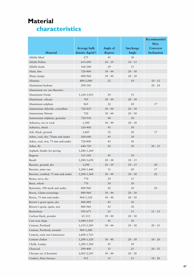
47
Material characteristics
Material
Average bulk
density (kg/m³)
Angle of
Repose
Surcharge
Angle
Recommended
Max.
Conveyor
Inclination
Alfalfa Meal 275 45 30
Alfalfa Pellets 655-690 20 - 29 10 - 15
Alfalfa Seeds 160-240 29 15
Alum, fine 720-800 30 - 44 20 - 30
Alum, lumpy 800-960 30 - 44 20 - 30
Alumina 800-1,040 22 10 10 - 12
Aluminium hydrate 290-545 20 - 24
Aluminium ore (see Bauxite)
Aluminium Oxide 1,120-1,925 29 15
Aluminium silicate 785 30 - 44 20 - 30
Aluminium sulphate 865 32 20 17
Ammonium chloride, crystalline 720-835 30 - 44 20 - 30
Ammonium Nitrate 720 30 - 44 20 - 30
Ammonium sulphate, granular 720-930 44 30
Asbestos, ore or rock 1,300 30 - 44 20 - 30
Asbestos, shred 320-400 45 30
Ash, black, ground 1,685 32 20 17
Ashes, coal, dry, 75mm and under 560-640 45 30
Ashes, coal, wet, 75 mm and under 720-800 45 30
Ashes, fly 640-720 42 30 20 - 25
Asphalt, binder for paving 1,280-1,360
Bagasse 115-160 45 30
Basalt 1,280-1,650 20 - 28 10 - 15
Bauxite, ground, dry 1,090 20 - 29 10 - 15 20
Bauxite, mine run 1,280-1,440 31 20 17
Bauxite, crushed, 75 mm and under 1,200-1,360 30 - 44 20 - 30 20
Beans, navy, dry 770 29 15
Beets, whole 770 50 30
Bentonite, 100 mesh and under 800-960 42 30 20
Borax, 12mm screenings 880-960 30 - 44 20 - 30
Borax, 75 mm and under 960-1,120 30 - 44 20 - 30
Brewer's grain spent, dry 400-480 45 30
Brewer's grain, spent, wet 880-960 45 30
Buckwheat 595-675 25 15 11 - 13
Carbon black, powder 65-115 30 - 44 20 - 30
Cast iron chips 1,440-1,925 45 30
Cement, Portland 1,155-1,585 30 - 44 20 - 30 20 - 23
Cement, Portland, aerated 960-1,200
Cement, rock (see Limestone) 1,600-1,765
Cement clinker 1,200-1,520 30 - 40 20 - 30 18 - 20
Chalk, Lumpy 1,200-1,360 45 30
Charcoal 290-400 35 25 20 - 25
Chrome ore (Chromite) 2,005-2,245 30 - 44 20 - 30
Cinders, blast furnace 915 35 25 18 - 20

48
Material
Average bulk
density (kg/m³)
Angle of
Repose
Surcharge
Angle
Recommended
Max.
Conveyor
Inclination
Cinder, coal 640 35 25 20
Clay (see also bentonite,
diatomaceous earth, fullers earth,
kaolin, and Marl
Clay calcined 1,280-1,600
Clay, ceramic, dry, fines 960-1,280 30 - 44 20 - 30 30 - 44
Clay, dry, fines 1,600-1,925 35 25 20 - 22
Clay, dry, lumpy 960-1,200 35 25 18 - 20
Clinker, cement (see cement clinker)
Coal, anthracite, river or culm,
10mm and under 960 35 25 18
Coal, antracite, sized 880-960 27 15 16
Coal, bituminous, mines 50 mesh
and under 800-865 45 30 24
Coal, bituminous, mined and sized 720-880 35 25 16
Coal, bituminous, mined, run of mine 720-880 38 25 18
*Coal, bitminous, mined, slack,12mm
and under 690-800 40 30 22
Coal, bituminous, stripping, not cleaned 800-960
Coal, lignite 640-880 38 25 22
Cocoa beans 480-720 30 - 44 20 - 30
Coffee, grean bean 515-720 30 - 44 20 - 30 10 - 15
Coffee, ground 400 23 10 10
Coke, loose 370-560 30 - 44 20 - 30 18
Coke, petroleum calcined 560-720 30 - 44 20 - 30 20
Coke breeze, 6mm and under 400-560 30 - 44 20 - 30 20 - 22
Compost 480-800
Concrete, cinder 1,440-1,600 12 - 30
Copper ore 1,925-2,405 30 - 44 20 - 30 20
Copper suphate 1,200-1,360 31 20 17
Corn, ear 900
Cottonseed, dry, de-linted 355-640 29 15 16
Cottonseed, dry, not de-linted 290-400 35 25 19
Cottonseed cake, crushed 720-720 30 - 44 20 - 30
Cottonseed cake, lumpy 640-720 30 - 44 20 - 30
Cryolite, dust 1,200-1,440 30 - 44 20 - 30
Cryolite, lumpy 1,440-1,600 30 - 44 20 - 30
Diatomaceous earth 175-225 30 - 44 20 - 30
Dicalcium phophate 640-800 45 30
Disodium phosphate 400-495 30 - 44 20 - 30
Dolomite, lumpy 1,280-1,600 30 - 44 20 - 30 22
Dolomite, pulverized 720 41 30
Earth, as excavated - dry 1,120-1,280 35 25 20
Earth, wet, containing clay 1,600-1,765 45 30 23
Emery 3,685 20 - 29 10 - 15
Feldspar, 12 mm screenings 1,120-1,360 38 25 18
Feldspar, 40mm to 75mm lumps 1,440-1,765 34 20 17
Feldspar, 200 mesh 1,600 30 - 44 20 - 30
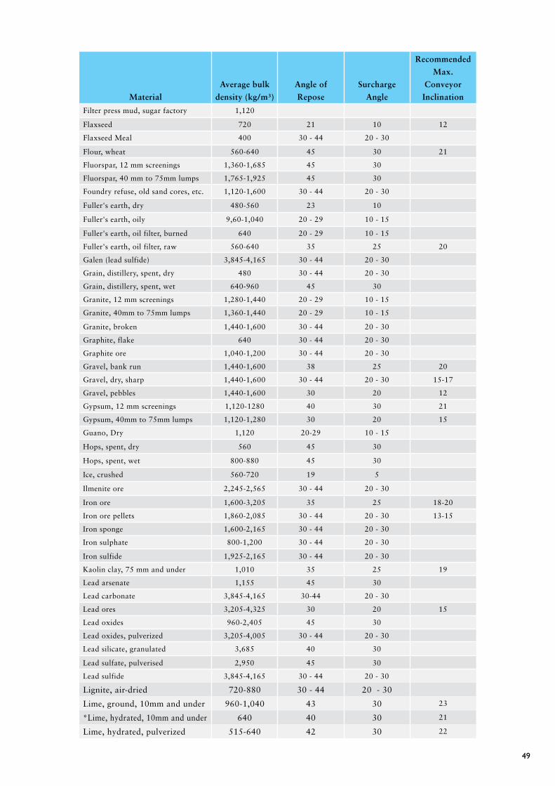
49
Material
Average bulk
density (kg/m³)
Angle of
Repose
Surcharge
Angle
Recommended
Max.
Conveyor
Inclination
Filter press mud, sugar factory 1,120
Flaxseed 720 21 10 12
Flaxseed Meal 400 30 - 44 20 - 30
Flour, wheat 560-640 45 30 21
Fluorspar, 12 mm screenings 1,360-1,685 45 30
Fluorspar, 40 mm to 75mm lumps 1,765-1,925 45 30
Foundry refuse, old sand cores, etc. 1,120-1,600 30 - 44 20 - 30
Fuller's earth, dry 480-560 23 10
Fuller's earth, oily 9,60-1,040 20 - 29 10 - 15
Fuller's earth, oil filter, burned 640 20 - 29 10 - 15
Fuller's earth, oil filter, raw 560-640 35 25 20
Galen (lead sulfide) 3,845-4,165 30 - 44 20 - 30
Grain, distillery, spent, dry 480 30 - 44 20 - 30
Grain, distillery, spent, wet 640-960 45 30
Granite, 12 mm screenings 1,280-1,440 20 - 29 10 - 15
Granite, 40mm to 75mm lumps 1,360-1,440 20 - 29 10 - 15
Granite, broken 1,440-1,600 30 - 44 20 - 30
Graphite, flake 640 30 - 44 20 - 30
Graphite ore 1,040-1,200 30 - 44 20 - 30
Gravel, bank run 1,440-1,600 38 25 20
Gravel, dry, sharp 1,440-1,600 30 - 44 20 - 30 15-17
Gravel, pebbles 1,440-1,600 30 20 12
Gypsum, 12 mm screenings 1,120-1280 40 30 21
Gypsum, 40mm to 75mm lumps 1,120-1,280 30 20 15
Guano, Dry 1,120 20-29 10 - 15
Hops, spent, dry 560 45 30
Hops, spent, wet 800-880 45 30
Ice, crushed 560-720 19 5
Ilmenite ore 2,245-2,565 30 - 44 20 - 30
Iron ore 1,600-3,205 35 25 18-20
Iron ore pellets 1,860-2,085 30 - 44 20 - 30 13-15
Iron sponge 1,600-2,165 30 - 44 20 - 30
Iron sulphate 800-1,200 30 - 44 20 - 30
Iron sulfide 1,925-2,165 30 - 44 20 - 30
Kaolin clay, 75 mm and under 1,010 35 25 19
Lead arsenate 1,155 45 30
Lead carbonate 3,845-4,165 30-44 20 - 30
Lead ores 3,205-4,325 30 20 15
Lead oxides 960-2,405 45 30
Lead oxides, pulverized 3,205-4,005 30 - 44 20 - 30
Lead silicate, granulated 3,685 40 30
Lead sulfate, pulverised 2,950 45 30
Lead sulfide 3,845-4,165 30 - 44 20 - 30
Lignite, air-dried 720-880 30 - 44 20 - 30
Lime, ground, 10mm and under 960-1,040 43 30 23
*Lime, hydrated, 10mm and under 640 40 30 21
Lime, hydrated, pulverized 515-640 42 30 22
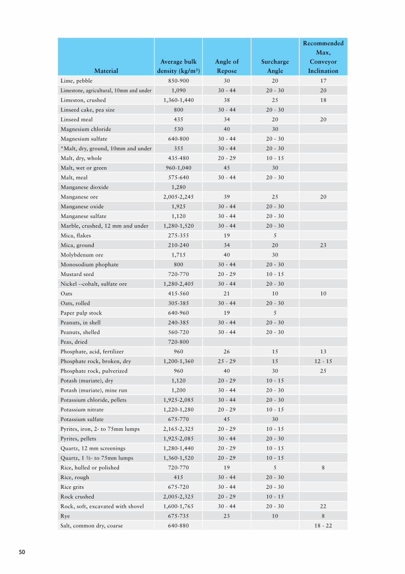
50
Material
Average bulk
density (kg/m³)
Angle of
Repose
Surcharge
Angle
Recommended
Max,
Conveyor
Inclination
Lime, pebble 850-900 30 20 17
Limestone, agricultural, 10mm and under 1,090 30 - 44 20 - 30 20
Limeston, crushed 1,360-1,440 38 25 18
Linseed cake, pea size 800 30 - 44 20 - 30
Linseed meal 435 34 20 20
Magnesium chloride 530 40 30
Magnesium sulfate 640-800 30 - 44 20 - 30
*Malt, dry, ground, 10mm and under 355 30 - 44 20 - 30
Malt, dry, whole 435-480 20 - 29 10 - 15
Malt, wet or green 960-1,040 45 30
Malt, meal 575-640 30 - 44 20 - 30
Manganese dioxide 1,280
Manganese ore 2,005-2,245 39 25 20
Manganese oxide 1,925 30 - 44 20 - 30
Manganese sulfate 1,120 30 - 44 20 - 30
Marble, crushed, 12 mm and under 1,280-1,520 30 - 44 20 - 30
Mica, flakes 275-355 19 5
Mica, ground 210-240 34 20 23
Molybdenum ore 1,715 40 30
Monosodium phophate 800 30 - 44 20 - 30
Mustard seed 720-770 20 - 29 10 - 15
Nickel --cobalt, sulfate ore 1,280-2,405 30 - 44 20 - 30
Oats 415-560 21 10 10
Oats, rolled 305-385 30 - 44 20 - 30
Paper pulp stock 640-960 19 5
Peanuts, in shell 240-385 30 - 44 20 - 30
Peanuts, shelled 560-720 30 - 44 20 - 30
Peas, dried 720-800
Phosphate, acid, fertilizer 960 26 15 13
Phosphate rock, broken, dry 1,200-1,360 25 - 29 15 12 - 15
Phosphate rock, pulverized 960 40 30 25
Potash (muriate), dry 1,120 20 - 29 10 - 15
Potash (muriate), mine run 1,200 30 - 44 20 - 30
Potassium chloride, pellets 1,925-2,085 30 - 44 20 - 30
Potassium nitrate 1,220-1,280 20 - 29 10 - 15
Potassium sulfate 675-770 45 30
Pyrites, iron, 2- to 75mm lumps 2,165-2,325 20 - 29 10 - 15
Pyrites, pellets 1,925-2,085 30 - 44 20 - 30
Quartz, 12 mm screenings 1,280-1,440 20 - 29 10 - 15
Quartz, 1 ½- to 75mm lumps 1,360-1,520 20 - 29 10 - 15
Rice, hulled or polished 720-770 19 5 8
Rice, rough 415 30 - 44 20 - 30
Rice grits 675-720 30 - 44 20 - 30
Rock crushed 2,005-2,325 20 - 29 10 - 15
Rock, soft, excavated with shovel 1,600-1,765 30 - 44 20 - 30 22
Rye 675-735 23 10 8
Salt, common dry, coarse 640-880 18 - 22
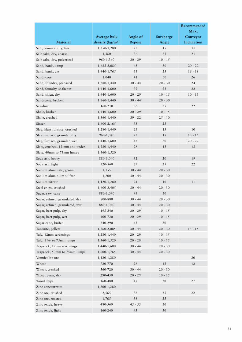
51
Material
Average bulk
density (kg/m³)
Angle of
Repose
Surcharge
Angle
Recommended
Max,
Conveyor
Inclination
Salt, common dry, fine 1,250-1,280 25 15 11
Salt cake, dry, coarse 1,360 36 25 21
Salt cake, dry, pulverized 960-1,360 20 - 29 10 - 15
Sand, bank, damp 1,685-2,085 45 30 20 - 22
Sand, bank, dry 1,440-1,765 35 25 16 - 18
Sand, core 1,040 41 30 26
Sand, foundry, prepared 1,280-1,440 30 - 44 20 - 30 24
Sand, foundry, shakeout 1,440-1,600 39 25 22
Sand, silica, dry 1,440-1,600 20 - 29 10 - 15 10 - 15
Sandstone, broken 1,360-1,440 30 - 44 20 - 30
Sawdust 160-210 36 25 22
Shale, broken 1,440-1,600 20 - 29 10 - 15
Shale, crushed 1,360-1,440 39 - 22 25 - 10
Sinter 1,600-2,165 35 25
Slag, blast furnace, crushed 1,280-1,440 25 15 10
Slag, furnace, granular, dry 960-1,040 25 15 13 - 16
Slag, furnace, granular, wet 1,440-1,600 45 30 20 - 22
Slate, crushed, 12 mm and under 1,280-1,440 28 15 15
Slate, 40mm to 75mm lumps 1,360-1,520
Soda ash, heavy 880-1,040 32 20 19
Soda ash, light 320-560 37 25 22
Sodium aluminate, ground 1,155 30 - 44 20 - 30
Sodium aluminium sulfate 1,200 30 - 44 20 - 30
Sodium nitrate 1,120-1,280 24 10 11
Steel chips, crushed 1,600-2,405 30 - 44 20 - 30
Sugar, raw, cane 880-1,040 45 30
Sugar, refined, granulated, dry 800-880 30 - 44 20 - 30
Sugar, refined, granulated, wet 880-1,040 30 - 44 20 - 30
Sugar, beet pulp, dry 195-240 20 - 29 10 - 15
Sugar, beet pulp, wet 400-720 20 - 29 10 - 15
Sugar cane, knifed 240-290 45 30
Taconite, pellets 1,860-2,085 30 - 44 20 - 30 13 - 15
Talc, 12mm screenings 1,280-1,440 20 - 29 10 - 15
Talc, 1 ½- to 75mm lumps 1,360-1,520 20 - 29 10 - 15
Traprock, 12mm screenings 1,440-1,600 30 - 44 20 - 30
Traprock, 50mm to 75mm lumps 1,600-1,765 30 - 44 20 - 30
Vermiculite ore 1,120-1,280 20
Wheat 720-770 28 15 12
Wheat, cracked 560-720 30 - 44 20 - 30
Wheat germ, dry 290-450 20 - 29 10 - 15
Wood chips 160-480 45 30 27
Zinc concentrates 1,200-1,280
Zinc ore, crushed 2,565 38 25 22
Zinc ore, roasted 1,765 38 25
Zinc oxide, heavy 480-560 45 - 55 30
Zinc oxide, light 160-240 45 30

52
Cross-sectional area
Actual cross sectional area will vary depending on the roller face width, belt thickness etc. please refer
to separate datasheets for specific roller face width information if required.
3 Roll Trough and Suspended Idler
20˚ Degree Trough
Belt Width
Surcharge angle (A)
0˚ 5˚ 10˚ 15˚ 20˚ 25˚
350 0.005 0.006 0.007 0.008 0.009 0.010
400 0.006 0.008 0.009 0.011 0.012 0.013
450 0.008 0.010 0.012 0.014 0.016 0.018
500 0.011 0.013 0.015 0.017 0.020 0.022
600 0.016 0.019 0.023 0.026 0.030 0.033
650 0.019 0.023 0.027 0.031 0.035 0.039
750 0.026 0.032 0.037 0.042 0.048 0.054
800 0.030 0.036 0.042 0.049 0.055 0.062
900 0.039 0.047 0.055 0.063 0.071 0.079
1,000 0.048 0.058 0.068 0.078 0.088 0.099
1,050 0.054 0.066 0.076 0.087 0.098 0.110
1,200 0.071 0.086 0.100 0.115 0.130 0.145
1,350 0.091 0.110 0.128 0.147 0.166 0.185
1,400 0.098 0.118 0.138 0.158 0.179 0.200
1,500 0.114 0.136 0.159 0.182 0.206 0.230
1,600 0.130 0.156 0.182 0.209 0.236 0.263
1,800 0.166 0.199 0.232 0.266 0.300 0.336
2,000 0.206 0.247 0.288 0.330 0.373 0.417
2,200 0.251 0.301 0.351 0.402 0.453 0.507
2,400 0.300 0.359 0.419 0.480 0.542 0.605
2,500 0.326 0.390 0.456 0.522 0.589 0.658
2,600 0.353 0.423 0.494 0.565 0.638 0.712
2,800 0.411 0.492 0.574 0.657 0.742 0.829
3,000 0.473 0.566 0.661 0.756 0.854 0.954
CROSS SECTIONAL AREA ( m2 ) TABLES
S = standard edge margin = 0.055W + 20mm
where W = belt width (mm)
A°
S
B°
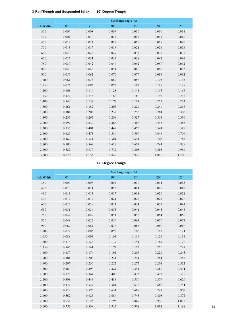
53
3 Roll Trough and Suspended Idler 30˚ Degree Trough
Belt Width
Surcharge angle (A)
0˚ 5˚ 10˚ 15˚ 20˚ 25˚
350 0.007 0.008 0.009 0.010 0.010 0.011
400 0.009 0.010 0.012 0.013 0.014 0.016
450 0.012 0.014 0.015 0.017 0.019 0.020
500 0.015 0.017 0.019 0.021 0.024 0.026
600 0.023 0.026 0.029 0.032 0.035 0.038
650 0.027 0.031 0.035 0.038 0.042 0.046
750 0.037 0.042 0.047 0.052 0.057 0.062
800 0.043 0.048 0.054 0.060 0.066 0.072
900 0.055 0.062 0.070 0.077 0.084 0.092
1,000 0.069 0.078 0.087 0.096 0.105 0.115
1,050 0.076 0.086 0.096 0.106 0.117 0.127
1,200 0.101 0.114 0.128 0.141 0.155 0.169
1,350 0.129 0.146 0.163 0.180 0.198 0.215
1,400 0.140 0.158 0.176 0.194 0.213 0.232
1,500 0.161 0.182 0.203 0.224 0.246 0.268
1,600 0.184 0.208 0.232 0.256 0.281 0.306
1,800 0.235 0.265 0.296 0.327 0.358 0.390
2,000 0.292 0.330 0.368 0.406 0.445 0.485
2,200 0.355 0.401 0.447 0.493 0.541 0.589
2,400 0.425 0.479 0.534 0.590 0.646 0.704
2,500 0.462 0.521 0.581 0.641 0.702 0.765
2,600 0.500 0.564 0.629 0.694 0.761 0.829
2,800 0.582 0.657 0.732 0.808 0.885 0.964
3,000 0.670 0.756 0.842 0.929 1.018 1.100
35˚ Degree Trough
Belt Width
Surcharge angle (A)
0˚ 5˚ 10˚ 15˚ 20˚ 25˚
350 0.007 0.008 0.009 0.010 0.011 0.012
400 0.010 0.011 0.013 0.014 0.015 0.016
450 0.013 0.015 0.017 0.018 0.020 0.021
500 0.017 0.019 0.021 0.023 0.025 0.027
600 0.026 0.029 0.031 0.034 0.037 0.041
650 0.031 0.034 0.038 0.041 0.045 0.048
750 0.042 0.047 0.051 0.056 0.061 0.066
800 0.048 0.053 0.059 0.064 0.070 0.075
900 0.062 0.069 0.076 0.083 0.090 0.097
1,000 0.077 0.086 0.095 0.103 0.112 0.121
1,050 0.086 0.095 0.105 0.114 0.124 0.134
1,200 0.114 0.126 0.139 0.151 0.164 0.177
1,350 0.145 0.161 0.177 0.193 0.210 0.227
1,400 0.157 0.174 0.191 0.209 0.226 0.245
1,500 0.181 0.200 0.221 0.241 0.261 0.282
1,600 0.207 0.230 0.252 0.275 0.298 0.322
1,800 0.264 0.293 0.322 0.351 0.380 0.411
2,000 0.328 0.364 0.400 0.436 0.472 0.510
2,200 0.399 0.443 0.486 0.530 0.574 0.620
2,400 0.477 0.529 0.581 0.633 0.686 0.741
2,500 0.519 0.575 0.631 0.688 0.746 0.805
2,600 0.562 0.623 0.684 0.745 0.808 0.872
2,800 0.654 0.725 0.795 0.867 0.940 1.015
3,000 0.753 0.834 0.915 0.998 1.082 1.168

54
3 Roll Trough and Suspended Idler 45˚ Degree Trough
Belt Width
Surcharge angle (A)
0˚ 5˚ 10˚ 15˚ 20˚ 25˚
350 0.009 0.010 0.010 0.011 0.012 0.013
400 0.012 0.013 0.014 0.015 0.016 0.017
450 0.016 0.017 0.019 0.020 0.021 0.023
500 0.020 0.022 0.024 0.025 0.027 0.029
600 0.030 0.033 0.035 0.038 0.041 0.043
650 0.036 0.039 0.042 0.045 0.048 0.051
750 0.049 0.053 0.057 0.061 0.066 0.070
800 0.057 0.061 0.066 0.071 0.075 0.080
900 0.073 0.079 0.085 0.091 0.097 0.103
1,000 0.091 0.098 0.106 0.113 0.121 0.129
1,050 0.101 0.109 0.117 0.126 0.134 0.143
1,200 0.134 0.144 0.155 0.166 0.177 0.189
1,350 0.171 0.185 0.198 0.212 0.227 0.241
1,400 0.184 0.199 0.214 0.229 0.244 0.260
1,500 0.213 0.230 0.247 0.264 0.282 0.300
1,600 0.243 0.263 0.282 0.302 0.322 0.343
1,800 0.310 0.335 0.360 0.385 0.410 0.437
2,000 0.385 0.416 0.447 0.478 0.510 0.542
2,200 0.469 0.506 0.543 0.581 0.620 0.659
2,400 0.560 0.604 0.649 0.694 0.740 0.787
2,500 0.609 0.657 0.705 0.754 0.804 0.856
2,60O 0.660 0.712 0.764 0.817 0.871 0.927
2,800 0.767 0.828 0.889 0.951 1.013 1.078
3,000 0.883 0.953 1.023 1.094 1.166 1.240
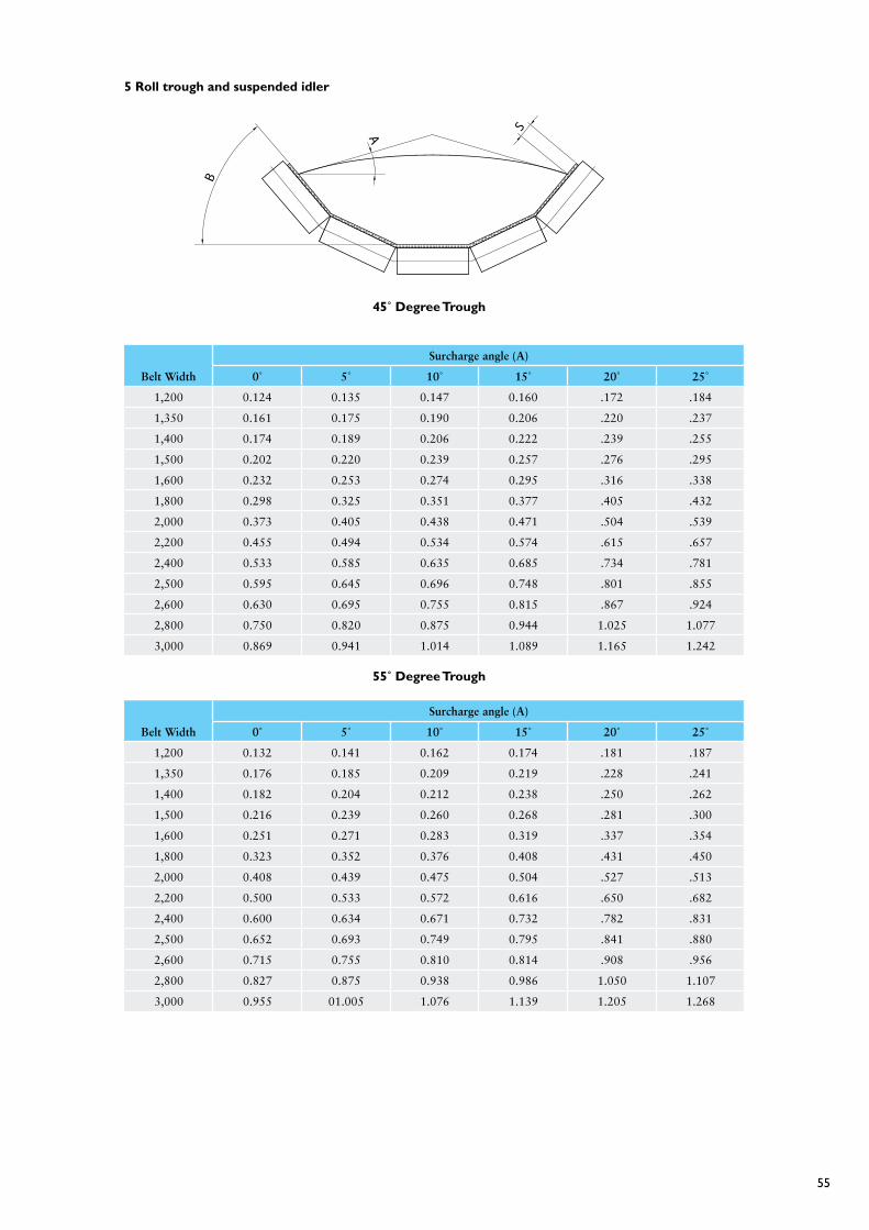
55
5 Roll trough and suspended idler
45˚ Degree Trough
Belt Width
Surcharge angle (A)
0˚ 5˚ 10˚ 15˚ 20˚ 25˚
1,200 0.124 0.135 0.147 0.160 .172 .184
1,350 0.161 0.175 0.190 0.206 .220 .237
1,400 0.174 0.189 0.206 0.222 .239 .255
1,500 0.202 0.220 0.239 0.257 .276 .295
1,600 0.232 0.253 0.274 0.295 .316 .338
1,800 0.298 0.325 0.351 0.377 .405 .432
2,000 0.373 0.405 0.438 0.471 .504 .539
2,200 0.455 0.494 0.534 0.574 .615 .657
2,400 0.533 0.585 0.635 0.685 .734 .781
2,500 0.595 0.645 0.696 0.748 .801 .855
2,600 0.630 0.695 0.755 0.815 .867 .924
2,800 0.750 0.820 0.875 0.944 1.025 1.077
3,000 0.869 0.941 1.014 1.089 1.165 1.242
55˚ Degree Trough
Belt Width
Surcharge angle (A)
0˚ 5˚ 10˚ 15˚ 20˚ 25˚
1,200 0.132 0.141 0.162 0.174 .181 .187
1,350 0.176 0.185 0.209 0.219 .228 .241
1,400 0.182 0.204 0.212 0.238 .250 .262
1,500 0.216 0.239 0.260 0.268 .281 .300
1,600 0.251 0.271 0.283 0.319 .337 .354
1,800 0.323 0.352 0.376 0.408 .431 .450
2,000 0.408 0.439 0.475 0.504 .527 .513
2,200 0.500 0.533 0.572 0.616 .650 .682
2,400 0.600 0.634 0.671 0.732 .782 .831
2,500 0.652 0.693 0.749 0.795 .841 .880
2,600 0.715 0.755 0.810 0.814 .908 .956
2,800 0.827 0.875 0.938 0.986 1.050 1.107
3,000 0.955 01.005 1.076 1.139 1.205 1.268
SA
B

56
60˚ Degree Trough
Belt Width
Surcharge angle (A)
0˚ 5˚ 10˚ 15˚ 20˚ 25˚
1,200 0.149 0.157 0.167 0.176 0.185 0.195
1,350 0.191 0.202 0.213 0.226 0.238 0.250
1,400 0.207 0.219 0.231 0.243 0.256 0.270
1,500 0.239 0.253 0.267 0.282 0.296 0.311
1,600 0.274 0.289 0.306 0.322 0.339 0.355
1,800 0.350 0.370 0.391 0.411 0.432 0.453
2,000 0.436 0.461 0.485 0.510 0.537 0.563
2,200 0.531 0.561 0.591 0.622 0.653 0.685
2,400 0.631 0.669 0.710 0.739 0.775 0.829
2,500 0.692 0.729 0.769 0.809 0.848 0.889
2,600 0.750 0.788 0.825 0.870 0.916 0.965
2,800 0.863 0.920 0.968 1.016 1.068 1.129
3,000 1.005 1.060 1.117 1.174 1.231 1.290

57
Sandvik is a registered trademark of the Sandvik Group © 2008 Sandvik
HA
200
Idle
r D
esig
n -
Rev
1
Sandvik is a high-technology engineering group with world-leading positions in selected areas-tools for metal working, advanced materials technology, and mining and construction. We employ more than 40,000 people and are represented in 30 countries.
Sandvik Mining and Construction represents one third of the overall Sandvik Group and serves a broad range of customers in construction, mineral exploration, mining and bulk materials handling. Our construction expertise covers quarrying, tunneling, demolition, recycling and other civil engineering applications. Our mining products and services support customers on the surface and underground including coal, iron, copper and gold mining.