Sandvik Cone Crusher Manual
188
qh330 Operator’s manual serial number Original Instructions
-
Upload
leon-mills -
Category
Documents
-
view
2.568 -
download
224
description
Sandvik Cone Crusher Manual
Transcript of Sandvik Cone Crusher Manual

qh33
0 Operator’s manual
serial number
Original Instructions

QH330 © Copyright Sandvik.All rights reserved. No parts of this document may be reproduced orcopied in any form or by any means without written permission from Sandvik.All data and information in this manual may be changed without further notice. Reservations for misprints.
For further information, please contact:
Sandvik Mining and ConstructionTullyvannon, BallygawleyCo. TyroneN. IrelandBT70 2HWTelephone: (+44) 028 8556 7799Facsimile: (+44) 028 8556 7007e-mail: [email protected]

Mobile Screener’s and Crusher’sTullyvannon, Ballygawley, Co. Tyrone, N. Ireland, BT70 2HW Tel: (+44) 028 855 67799 Fac: (+44) 028 855 67007
MANUFACTURERS E.C. “DECLARATION OF CONFORMITY”
QH330
Serial No: ________________
Manufacturer’s DeclarationWe hereby declare, under sole responsibility, that the above machinery complies with theprovisions of following EC Directives.
European Machinery Directive 98/37/EC.Electromagnetic Compatibility Directive 89/336/EEC, amended by 92/31/EEC and 93/68/EEC on the approximation of the laws of the Member States relating toelectromagnetic compatibility.Low Voltage Directive 73/23/EEC amended by 93/68/EEC on the harmonisation of thelaws of the Member States relating to electrical equipment designed for use within certainvoltage limits.
CE mark affixed, Date: _________________
Basis on which conformity is declaredThe above machinery satisfies the relevant essential health and safety requirements of theEuropean Machinery Directive where appropriate.
The above machinery complies with the protection requirements of the EMC Directive and the principal elements of the safety objectives of the Low Voltage Directive.
Signed on behalf of the manufacturer: Date:
____________ Operations Director

This Page is intentionally left blank

Copyright © Sandvik Mobile Screener’s & Crusher’s
ID:QJ330.en.ver1
Contents1.0 Safety Section 9Safety Essentials. . . . . . . . . . . . . . . . . . . . . . . . . . . . . . . . . . . . . . . . . . . . . . . . . . . . . . . . . . . . . . . . . . . . . . . 10Safety Signs and Labels . . . . . . . . . . . . . . . . . . . . . . . . . . . . . . . . . . . . . . . . . . . . . . . . . . . . . . . . . . . . . . . . . 11Safety Hazards Pertaining to the Equipment . . . . . . . . . . . . . . . . . . . . . . . . . . . . . . . . . . . . . . . . . . . . . . . . . 11
Symbols for Mandatory Actions . . . . . . . . . . . . . . . . . . . . . . . . . . . . . . . . . . . . . . . . . . . . . . . . . . . . . . . . . 12Symbols for Prohibited Actions . . . . . . . . . . . . . . . . . . . . . . . . . . . . . . . . . . . . . . . . . . . . . . . . . . . . . . . . . 13Hazard Symbols. . . . . . . . . . . . . . . . . . . . . . . . . . . . . . . . . . . . . . . . . . . . . . . . . . . . . . . . . . . . . . . . . . . . . 13Machine Legend Plate . . . . . . . . . . . . . . . . . . . . . . . . . . . . . . . . . . . . . . . . . . . . . . . . . . . . . . . . . . . . . . . . 14
Component Safety Features . . . . . . . . . . . . . . . . . . . . . . . . . . . . . . . . . . . . . . . . . . . . . . . . . . . . . . . . . . . . . . 15Features for Operator Safety . . . . . . . . . . . . . . . . . . . . . . . . . . . . . . . . . . . . . . . . . . . . . . . . . . . . . . . . . . . . . 15Environmental Safety . . . . . . . . . . . . . . . . . . . . . . . . . . . . . . . . . . . . . . . . . . . . . . . . . . . . . . . . . . . . . . . . . . . 15
Hazardous Materials . . . . . . . . . . . . . . . . . . . . . . . . . . . . . . . . . . . . . . . . . . . . . . . . . . . . . . . . . . . . . . . . . 16Machine Disposal. . . . . . . . . . . . . . . . . . . . . . . . . . . . . . . . . . . . . . . . . . . . . . . . . . . . . . . . . . . . . . . . . . . . 16
Personal Protective Equipment (PPE) . . . . . . . . . . . . . . . . . . . . . . . . . . . . . . . . . . . . . . . . . . . . . . . . . . . . . . 17Entanglement Hazards . . . . . . . . . . . . . . . . . . . . . . . . . . . . . . . . . . . . . . . . . . . . . . . . . . . . . . . . . . . . . . . 17Required Personal Protective Equipment . . . . . . . . . . . . . . . . . . . . . . . . . . . . . . . . . . . . . . . . . . . . . . . . . 17
Measure Noise Level . . . . . . . . . . . . . . . . . . . . . . . . . . . . . . . . . . . . . . . . . . . . . . . . . . . . . . . . . . . . . . . . . . . 19Vibration Levels. . . . . . . . . . . . . . . . . . . . . . . . . . . . . . . . . . . . . . . . . . . . . . . . . . . . . . . . . . . . . . . . . . . . . . . . 19Organisational Safety Measures . . . . . . . . . . . . . . . . . . . . . . . . . . . . . . . . . . . . . . . . . . . . . . . . . . . . . . . . . . . 20Personnel Qualifications, Requirements and Responsiblities. . . . . . . . . . . . . . . . . . . . . . . . . . . . . . . . . . . . . 20Safety Advice Regarding Specific Operational Phases . . . . . . . . . . . . . . . . . . . . . . . . . . . . . . . . . . . . . . . . . 21
Standard Operation . . . . . . . . . . . . . . . . . . . . . . . . . . . . . . . . . . . . . . . . . . . . . . . . . . . . . . . . . . . . . . . . . . 21Blockage or Malfunction. . . . . . . . . . . . . . . . . . . . . . . . . . . . . . . . . . . . . . . . . . . . . . . . . . . . . . . . . . . . . . . 21Unguarded Areas. . . . . . . . . . . . . . . . . . . . . . . . . . . . . . . . . . . . . . . . . . . . . . . . . . . . . . . . . . . . . . . . . . . . 21
Special Work, Including Equipment Maintenance and Repairs During Operation, Disposal of Parts, and Haz-ardous Materials . . . . . . . . . . . . . . . . . . . . . . . . . . . . . . . . . . . . . . . . . . . . . . . . . . . . . . . . . . . . . . . . . . . . . . . 22
Securing the Equipment Before Performing Maintenance. . . . . . . . . . . . . . . . . . . . . . . . . . . . . . . . . . . . . 22Maintenance Site Conditions . . . . . . . . . . . . . . . . . . . . . . . . . . . . . . . . . . . . . . . . . . . . . . . . . . . . . . . . . . . 22 Replacement & Removal of Components. . . . . . . . . . . . . . . . . . . . . . . . . . . . . . . . . . . . . . . . . . . . . . . . . 22 Climbing, Falling . . . . . . . . . . . . . . . . . . . . . . . . . . . . . . . . . . . . . . . . . . . . . . . . . . . . . . . . . . . . . . . . . . . . 23Safety Considerations During Maintenance. . . . . . . . . . . . . . . . . . . . . . . . . . . . . . . . . . . . . . . . . . . . . . . . 24Safety Considerations During Cleaning . . . . . . . . . . . . . . . . . . . . . . . . . . . . . . . . . . . . . . . . . . . . . . . . . . . 24Removal of Safety Devices and Guards . . . . . . . . . . . . . . . . . . . . . . . . . . . . . . . . . . . . . . . . . . . . . . . . . . 24Surrounding Structures . . . . . . . . . . . . . . . . . . . . . . . . . . . . . . . . . . . . . . . . . . . . . . . . . . . . . . . . . . . . . . . 25Safety When Refueling . . . . . . . . . . . . . . . . . . . . . . . . . . . . . . . . . . . . . . . . . . . . . . . . . . . . . . . . . . . . . . . 25
Specific Hazards . . . . . . . . . . . . . . . . . . . . . . . . . . . . . . . . . . . . . . . . . . . . . . . . . . . . . . . . . . . . . . . . . . . . . . . 26Electrical Energy . . . . . . . . . . . . . . . . . . . . . . . . . . . . . . . . . . . . . . . . . . . . . . . . . . . . . . . . . . . . . . . . . . . . 26Battery . . . . . . . . . . . . . . . . . . . . . . . . . . . . . . . . . . . . . . . . . . . . . . . . . . . . . . . . . . . . . . . . . . . . . . . . . . . . 27Gas, Dust, Steam, Smoke and Noise . . . . . . . . . . . . . . . . . . . . . . . . . . . . . . . . . . . . . . . . . . . . . . . . . . . . 27Welding or Naked Flames . . . . . . . . . . . . . . . . . . . . . . . . . . . . . . . . . . . . . . . . . . . . . . . . . . . . . . . . . . . . . 28Hydraulic Equipment . . . . . . . . . . . . . . . . . . . . . . . . . . . . . . . . . . . . . . . . . . . . . . . . . . . . . . . . . . . . . . . . . 28Hazardous Substances . . . . . . . . . . . . . . . . . . . . . . . . . . . . . . . . . . . . . . . . . . . . . . . . . . . . . . . . . . . . . . . 29
Safety Concerns . . . . . . . . . . . . . . . . . . . . . . . . . . . . . . . . . . . . . . . . . . . . . . . . . . . . . . . . . . . . . . . . . . . . . . . 30Systems Immobilization Procedure . . . . . . . . . . . . . . . . . . . . . . . . . . . . . . . . . . . . . . . . . . . . . . . . . . . . . . 31Fundmental Safety Instructions And Product Application . . . . . . . . . . . . . . . . . . . . . . . . . . . . . . . . . . . . . 31Operational Safety Considerations . . . . . . . . . . . . . . . . . . . . . . . . . . . . . . . . . . . . . . . . . . . . . . . . . . . . . . 32Operator Selection And Qualification. . . . . . . . . . . . . . . . . . . . . . . . . . . . . . . . . . . . . . . . . . . . . . . . . . . . . 33Safety During Maintenance And Repair. . . . . . . . . . . . . . . . . . . . . . . . . . . . . . . . . . . . . . . . . . . . . . . . . . . 33Special Considerations For Maintenance And Repair Of Electrical System . . . . . . . . . . . . . . . . . . . . . . . 35Special Considerations For Maintenance Or Repair with Welding . . . . . . . . . . . . . . . . . . . . . . . . . . . . . . 36Special Considerations For Maintenance Or Repair Of Hydraulic System . . . . . . . . . . . . . . . . . . . . . . . . 36Handling And Disposal Of Hazardous Components And Materials . . . . . . . . . . . . . . . . . . . . . . . . . . . . . . 37Warning Concerning Crystalline Silica And Similar Particulates.. . . . . . . . . . . . . . . . . . . . . . . . . . . . . . . . 37Special Considerations Concerning Dust Disposal.. . . . . . . . . . . . . . . . . . . . . . . . . . . . . . . . . . . . . . . . . . 37

ContentsSpecial Considerations For Transport Of The QH330 . . . . . . . . . . . . . . . . . . . . . . . . . . . . . . . . . . . . . . . . 38Special Considerations For Maintenance Or Repair To The QH330’s Tires . . . . . . . . . . . . . . . . . . . . . . . 38Location Of Emergency Stops On QH330 . . . . . . . . . . . . . . . . . . . . . . . . . . . . . . . . . . . . . . . . . . . . . . . . . 38
2.0 Technical and Transport 39Technical Information . . . . . . . . . . . . . . . . . . . . . . . . . . . . . . . . . . . . . . . . . . . . . . . . . . . . . . . . . . . . . . . . . . . 40
Standard Features . . . . . . . . . . . . . . . . . . . . . . . . . . . . . . . . . . . . . . . . . . . . . . . . . . . . . . . . . . . . . . . . . . . 40Options. . . . . . . . . . . . . . . . . . . . . . . . . . . . . . . . . . . . . . . . . . . . . . . . . . . . . . . . . . . . . . . . . . . . . . . . . . . . 40Transport and Working Dimensions. . . . . . . . . . . . . . . . . . . . . . . . . . . . . . . . . . . . . . . . . . . . . . . . . . . . . . 41
Indentification of Main Units . . . . . . . . . . . . . . . . . . . . . . . . . . . . . . . . . . . . . . . . . . . . . . . . . . . . . . . . . . . . . . 43Specification of Main Units . . . . . . . . . . . . . . . . . . . . . . . . . . . . . . . . . . . . . . . . . . . . . . . . . . . . . . . . . . . . . . . 43
Feeder Hopper. . . . . . . . . . . . . . . . . . . . . . . . . . . . . . . . . . . . . . . . . . . . . . . . . . . . . . . . . . . . . . . . . . . . . . 43Feed Conveyor . . . . . . . . . . . . . . . . . . . . . . . . . . . . . . . . . . . . . . . . . . . . . . . . . . . . . . . . . . . . . . . . . . . . . 44Crusher . . . . . . . . . . . . . . . . . . . . . . . . . . . . . . . . . . . . . . . . . . . . . . . . . . . . . . . . . . . . . . . . . . . . . . . . . . . 44 Main Conveyor . . . . . . . . . . . . . . . . . . . . . . . . . . . . . . . . . . . . . . . . . . . . . . . . . . . . . . . . . . . . . . . . . . . . . 44Tracks . . . . . . . . . . . . . . . . . . . . . . . . . . . . . . . . . . . . . . . . . . . . . . . . . . . . . . . . . . . . . . . . . . . . . . . . . . . . 44Powerunit . . . . . . . . . . . . . . . . . . . . . . . . . . . . . . . . . . . . . . . . . . . . . . . . . . . . . . . . . . . . . . . . . . . . . . . . . . 44
3.0 Product Overview 45Product Overview . . . . . . . . . . . . . . . . . . . . . . . . . . . . . . . . . . . . . . . . . . . . . . . . . . . . . . . . . . . . . . . . . . . . . . 46
Major Components. . . . . . . . . . . . . . . . . . . . . . . . . . . . . . . . . . . . . . . . . . . . . . . . . . . . . . . . . . . . . . . . . . . 46Identification and Operation of the QH330 Controls . . . . . . . . . . . . . . . . . . . . . . . . . . . . . . . . . . . . . . . . . 47Main Control Panel . . . . . . . . . . . . . . . . . . . . . . . . . . . . . . . . . . . . . . . . . . . . . . . . . . . . . . . . . . . . . . . . . . 48Main Operations Menu. . . . . . . . . . . . . . . . . . . . . . . . . . . . . . . . . . . . . . . . . . . . . . . . . . . . . . . . . . . . . . . . 49Hydraulic Controls . . . . . . . . . . . . . . . . . . . . . . . . . . . . . . . . . . . . . . . . . . . . . . . . . . . . . . . . . . . . . . . . . . . 51Remote Control Unit . . . . . . . . . . . . . . . . . . . . . . . . . . . . . . . . . . . . . . . . . . . . . . . . . . . . . . . . . . . . . . . . . 52Hydraulics . . . . . . . . . . . . . . . . . . . . . . . . . . . . . . . . . . . . . . . . . . . . . . . . . . . . . . . . . . . . . . . . . . . . . . . . . 53Lubrication System . . . . . . . . . . . . . . . . . . . . . . . . . . . . . . . . . . . . . . . . . . . . . . . . . . . . . . . . . . . . . . . . . . 54Hydroset System . . . . . . . . . . . . . . . . . . . . . . . . . . . . . . . . . . . . . . . . . . . . . . . . . . . . . . . . . . . . . . . . . . . . 55
4.0 Commissioning and Shut Down 57Commissioning & Shutdown Safety . . . . . . . . . . . . . . . . . . . . . . . . . . . . . . . . . . . . . . . . . . . . . . . . . . . . . . . . 58
What Are The Hazards And Dangers? . . . . . . . . . . . . . . . . . . . . . . . . . . . . . . . . . . . . . . . . . . . . . . . . . . . 58Who is at Risk . . . . . . . . . . . . . . . . . . . . . . . . . . . . . . . . . . . . . . . . . . . . . . . . . . . . . . . . . . . . . . . . . . . . . . 58Are Precautions Adequate? . . . . . . . . . . . . . . . . . . . . . . . . . . . . . . . . . . . . . . . . . . . . . . . . . . . . . . . . . . . . 58When carrying out maintenace or adjustment . . . . . . . . . . . . . . . . . . . . . . . . . . . . . . . . . . . . . . . . . . . . . . 58
Commissioning . . . . . . . . . . . . . . . . . . . . . . . . . . . . . . . . . . . . . . . . . . . . . . . . . . . . . . . . . . . . . . . . . . . . . . . . 59Preparation for Machine STARTUP. . . . . . . . . . . . . . . . . . . . . . . . . . . . . . . . . . . . . . . . . . . . . . . . . . . . . . 59Start-up Sequence For Tracking Machine . . . . . . . . . . . . . . . . . . . . . . . . . . . . . . . . . . . . . . . . . . . . . . . . . 60Machine Set-Up . . . . . . . . . . . . . . . . . . . . . . . . . . . . . . . . . . . . . . . . . . . . . . . . . . . . . . . . . . . . . . . . . . . . . 62
Operating the QH330 . . . . . . . . . . . . . . . . . . . . . . . . . . . . . . . . . . . . . . . . . . . . . . . . . . . . . . . . . . . . . . . . . . . 64Start-up Sequence For Running the Crusher . . . . . . . . . . . . . . . . . . . . . . . . . . . . . . . . . . . . . . . . . . . . . . 64
Auto Run Mode . . . . . . . . . . . . . . . . . . . . . . . . . . . . . . . . . . . . . . . . . . . . . . . . . . . . . . . . . . . . . . . . . . . . . . . . 65CSS Adjustment. . . . . . . . . . . . . . . . . . . . . . . . . . . . . . . . . . . . . . . . . . . . . . . . . . . . . . . . . . . . . . . . . . . . . 66Calibratio . . . . . . . . . . . . . . . . . . . . . . . . . . . . . . . . . . . . . . . . . . . . . . . . . . . . . . . . . . . . . . . . . . . . . . . . . . 66Auto Start Up Sequence . . . . . . . . . . . . . . . . . . . . . . . . . . . . . . . . . . . . . . . . . . . . . . . . . . . . . . . . . . . . . . 67Auto Stop Sequence . . . . . . . . . . . . . . . . . . . . . . . . . . . . . . . . . . . . . . . . . . . . . . . . . . . . . . . . . . . . . . . . . 68Manual Run Mode . . . . . . . . . . . . . . . . . . . . . . . . . . . . . . . . . . . . . . . . . . . . . . . . . . . . . . . . . . . . . . . . . . . 69Manual Start Up . . . . . . . . . . . . . . . . . . . . . . . . . . . . . . . . . . . . . . . . . . . . . . . . . . . . . . . . . . . . . . . . . . . . . 70Feed Conveyor Adjustment . . . . . . . . . . . . . . . . . . . . . . . . . . . . . . . . . . . . . . . . . . . . . . . . . . . . . . . . . . . . 70Manual Stop Sequence . . . . . . . . . . . . . . . . . . . . . . . . . . . . . . . . . . . . . . . . . . . . . . . . . . . . . . . . . . . . . . . 71Machine Shut Down. . . . . . . . . . . . . . . . . . . . . . . . . . . . . . . . . . . . . . . . . . . . . . . . . . . . . . . . . . . . . . . . . . 71Emergency Stop . . . . . . . . . . . . . . . . . . . . . . . . . . . . . . . . . . . . . . . . . . . . . . . . . . . . . . . . . . . . . . . . . . . . 73

Copyright © Sandvik Mobile Screener’s & Crusher’s
ID:QJ330.en.ver1
Contents5.0 Operation 75Section under construction . . . . . . . . . . . . . . . . . . . . . . . . . . . . . . . . . . . . . . . . . . . . . . . . . . . . . . . . . . . . . . . 76
6.0 Maintenance 77Maintenance Safety . . . . . . . . . . . . . . . . . . . . . . . . . . . . . . . . . . . . . . . . . . . . . . . . . . . . . . . . . . . . . . . . . . . . 78
What Are The Hazards And Dangers? . . . . . . . . . . . . . . . . . . . . . . . . . . . . . . . . . . . . . . . . . . . . . . . . . . . 78Who is at Risk . . . . . . . . . . . . . . . . . . . . . . . . . . . . . . . . . . . . . . . . . . . . . . . . . . . . . . . . . . . . . . . . . . . . . . 78Are Precautions Adequate? . . . . . . . . . . . . . . . . . . . . . . . . . . . . . . . . . . . . . . . . . . . . . . . . . . . . . . . . . . . . 78When carrying out maintenace or adjustment . . . . . . . . . . . . . . . . . . . . . . . . . . . . . . . . . . . . . . . . . . . . . . 78
Maintenance Schedule . . . . . . . . . . . . . . . . . . . . . . . . . . . . . . . . . . . . . . . . . . . . . . . . . . . . . . . . . . . . . . . . . . 79Powerunit Engine and Hydraulic . . . . . . . . . . . . . . . . . . . . . . . . . . . . . . . . . . . . . . . . . . . . . . . . . . . . . . . . 79Crusher, Feeder, Conveyors and General . . . . . . . . . . . . . . . . . . . . . . . . . . . . . . . . . . . . . . . . . . . . . . . . . 80V-Belt Tension . . . . . . . . . . . . . . . . . . . . . . . . . . . . . . . . . . . . . . . . . . . . . . . . . . . . . . . . . . . . . . . . . . . . . . 82Engine Maintenace . . . . . . . . . . . . . . . . . . . . . . . . . . . . . . . . . . . . . . . . . . . . . . . . . . . . . . . . . . . . . . . . . . 83Air Cleaner Maintenance . . . . . . . . . . . . . . . . . . . . . . . . . . . . . . . . . . . . . . . . . . . . . . . . . . . . . . . . . . . . . . 83Check / Adding Fuel. . . . . . . . . . . . . . . . . . . . . . . . . . . . . . . . . . . . . . . . . . . . . . . . . . . . . . . . . . . . . . . . . . 83Battery Maintenace . . . . . . . . . . . . . . . . . . . . . . . . . . . . . . . . . . . . . . . . . . . . . . . . . . . . . . . . . . . . . . . . . . 84Special Considerations For Maintenance Or Repair with Welding . . . . . . . . . . . . . . . . . . . . . . . . . . . . . . 84
Hydraulic System . . . . . . . . . . . . . . . . . . . . . . . . . . . . . . . . . . . . . . . . . . . . . . . . . . . . . . . . . . . . . . . . . . . . . . 85Changing the Hydraulic Oil . . . . . . . . . . . . . . . . . . . . . . . . . . . . . . . . . . . . . . . . . . . . . . . . . . . . . . . . . . . . 86Changing The Return Line Fliter . . . . . . . . . . . . . . . . . . . . . . . . . . . . . . . . . . . . . . . . . . . . . . . . . . . . . . . . 87
Lubrication System . . . . . . . . . . . . . . . . . . . . . . . . . . . . . . . . . . . . . . . . . . . . . . . . . . . . . . . . . . . . . . . . . . . . . 88Lubrication Oil . . . . . . . . . . . . . . . . . . . . . . . . . . . . . . . . . . . . . . . . . . . . . . . . . . . . . . . . . . . . . . . . . . . . . . 88Changing the Lubrication Oil:. . . . . . . . . . . . . . . . . . . . . . . . . . . . . . . . . . . . . . . . . . . . . . . . . . . . . . . . . . . 89Hydroset System . . . . . . . . . . . . . . . . . . . . . . . . . . . . . . . . . . . . . . . . . . . . . . . . . . . . . . . . . . . . . . . . . . . . 90Changing the Hydroset Oil: . . . . . . . . . . . . . . . . . . . . . . . . . . . . . . . . . . . . . . . . . . . . . . . . . . . . . . . . . . . . 91Track Maintenance . . . . . . . . . . . . . . . . . . . . . . . . . . . . . . . . . . . . . . . . . . . . . . . . . . . . . . . . . . . . . . . . . . 92Checking the Track Tension . . . . . . . . . . . . . . . . . . . . . . . . . . . . . . . . . . . . . . . . . . . . . . . . . . . . . . . . . . . 92Tighten the Tracks . . . . . . . . . . . . . . . . . . . . . . . . . . . . . . . . . . . . . . . . . . . . . . . . . . . . . . . . . . . . . . . . . . . 93Loosen the Tracks . . . . . . . . . . . . . . . . . . . . . . . . . . . . . . . . . . . . . . . . . . . . . . . . . . . . . . . . . . . . . . . . . . . 93Track Drive Units . . . . . . . . . . . . . . . . . . . . . . . . . . . . . . . . . . . . . . . . . . . . . . . . . . . . . . . . . . . . . . . . . . . . 94
Conveyor Belt Maintenance . . . . . . . . . . . . . . . . . . . . . . . . . . . . . . . . . . . . . . . . . . . . . . . . . . . . . . . . . . . . . . 95Tensioning the Feed Conveyor Belt. . . . . . . . . . . . . . . . . . . . . . . . . . . . . . . . . . . . . . . . . . . . . . . . . . . . . . 95Tensioning The Main Conveyor belt . . . . . . . . . . . . . . . . . . . . . . . . . . . . . . . . . . . . . . . . . . . . . . . . . . . . . 96Tracking the Belts . . . . . . . . . . . . . . . . . . . . . . . . . . . . . . . . . . . . . . . . . . . . . . . . . . . . . . . . . . . . . . . . . . . 97Emptying the Fuel Filter Water Trap . . . . . . . . . . . . . . . . . . . . . . . . . . . . . . . . . . . . . . . . . . . . . . . . . . . . . 98Maintenance Data . . . . . . . . . . . . . . . . . . . . . . . . . . . . . . . . . . . . . . . . . . . . . . . . . . . . . . . . . . . . . . . . . . . 99Hydraulic Oil Requirements for QH330 Machines . . . . . . . . . . . . . . . . . . . . . . . . . . . . . . . . . . . . . . . . . . . 99
Lubricants and Fluids . . . . . . . . . . . . . . . . . . . . . . . . . . . . . . . . . . . . . . . . . . . . . . . . . . . . . . . . . . . . . . . . . . 101Greasing Schedule . . . . . . . . . . . . . . . . . . . . . . . . . . . . . . . . . . . . . . . . . . . . . . . . . . . . . . . . . . . . . . . . . 102Care of chrome . . . . . . . . . . . . . . . . . . . . . . . . . . . . . . . . . . . . . . . . . . . . . . . . . . . . . . . . . . . . . . . . . . . . 103
7.0 Trouble Shooting and Warranty 105Trouble Shootting . . . . . . . . . . . . . . . . . . . . . . . . . . . . . . . . . . . . . . . . . . . . . . . . . . . . . . . . . . . . . . . . . . . . . 106
Setting the date/time . . . . . . . . . . . . . . . . . . . . . . . . . . . . . . . . . . . . . . . . . . . . . . . . . . . . . . . . . . . . . . . . 106Diagnostic Screen . . . . . . . . . . . . . . . . . . . . . . . . . . . . . . . . . . . . . . . . . . . . . . . . . . . . . . . . . . . . . . . . . . 107Engine Status. . . . . . . . . . . . . . . . . . . . . . . . . . . . . . . . . . . . . . . . . . . . . . . . . . . . . . . . . . . . . . . . . . . . . . 108
Service Log and Faults . . . . . . . . . . . . . . . . . . . . . . . . . . . . . . . . . . . . . . . . . . . . . . . . . . . . . . . . . . . . . . . . . 109Service Logging Screen. . . . . . . . . . . . . . . . . . . . . . . . . . . . . . . . . . . . . . . . . . . . . . . . . . . . . . . . . . . . . . 110Faults Events Screen. . . . . . . . . . . . . . . . . . . . . . . . . . . . . . . . . . . . . . . . . . . . . . . . . . . . . . . . . . . . . . . . 110Filter Fault History Screen . . . . . . . . . . . . . . . . . . . . . . . . . . . . . . . . . . . . . . . . . . . . . . . . . . . . . . . . . . . . 110
Machine Shutdown Faults. . . . . . . . . . . . . . . . . . . . . . . . . . . . . . . . . . . . . . . . . . . . . . . . . . . . . . . . . . . . . . . 111Cat C13 Diagnostic Codes. . . . . . . . . . . . . . . . . . . . . . . . . . . . . . . . . . . . . . . . . . . . . . . . . . . . . . . . . . . . 112
Warranty . . . . . . . . . . . . . . . . . . . . . . . . . . . . . . . . . . . . . . . . . . . . . . . . . . . . . . . . . . . . . . . . . . . . . . . . . . . . 114

ContentsStandard Terms and Conditions . . . . . . . . . . . . . . . . . . . . . . . . . . . . . . . . . . . . . . . . . . . . . . . . . . . . . . . 114Commissioning and Warranty Registration . . . . . . . . . . . . . . . . . . . . . . . . . . . . . . . . . . . . . . . . . . . . . . . 118
CAT Register Instructions . . . . . . . . . . . . . . . . . . . . . . . . . . . . . . . . . . . . . . . . . . . . . . . . . . . . . . . . . . . . . . . 119CAT C Series Warranty Statement . . . . . . . . . . . . . . . . . . . . . . . . . . . . . . . . . . . . . . . . . . . . . . . . . . . . . 120Maintenance Log . . . . . . . . . . . . . . . . . . . . . . . . . . . . . . . . . . . . . . . . . . . . . . . . . . . . . . . . . . . . . . . . . . . 122
8.0 Spare Parts 127Spare Parts . . . . . . . . . . . . . . . . . . . . . . . . . . . . . . . . . . . . . . . . . . . . . . . . . . . . . . . . . . . . . . . . . . . . . . . . . . 128
Spare Parts illustrations . . . . . . . . . . . . . . . . . . . . . . . . . . . . . . . . . . . . . . . . . . . . . . . . . . . . . . . . . . . . . . 128Ordering Procedure: . . . . . . . . . . . . . . . . . . . . . . . . . . . . . . . . . . . . . . . . . . . . . . . . . . . . . . . . . . . . . . . . 128
Machine Assemblies . . . . . . . . . . . . . . . . . . . . . . . . . . . . . . . . . . . . . . . . . . . . . . . . . . . . . . . . . . . . . . . . . . . 128Top Level . . . . . . . . . . . . . . . . . . . . . . . . . . . . . . . . . . . . . . . . . . . . . . . . . . . . . . . . . . . . . . . . . . . . . . . . . 129QH330 Chassis assembly . . . . . . . . . . . . . . . . . . . . . . . . . . . . . . . . . . . . . . . . . . . . . . . . . . . . . . . . . . . . 130Hydraulic Tank . . . . . . . . . . . . . . . . . . . . . . . . . . . . . . . . . . . . . . . . . . . . . . . . . . . . . . . . . . . . . . . . . . . . . 132Diesel Tank . . . . . . . . . . . . . . . . . . . . . . . . . . . . . . . . . . . . . . . . . . . . . . . . . . . . . . . . . . . . . . . . . . . . . . . 133Feed Conveyor . . . . . . . . . . . . . . . . . . . . . . . . . . . . . . . . . . . . . . . . . . . . . . . . . . . . . . . . . . . . . . . . . . . . 134Feeder Support Framet . . . . . . . . . . . . . . . . . . . . . . . . . . . . . . . . . . . . . . . . . . . . . . . . . . . . . . . . . . . . . . 137Main Conveyor. . . . . . . . . . . . . . . . . . . . . . . . . . . . . . . . . . . . . . . . . . . . . . . . . . . . . . . . . . . . . . . . . . . . . 138Main Conveyor lower section. . . . . . . . . . . . . . . . . . . . . . . . . . . . . . . . . . . . . . . . . . . . . . . . . . . . . . . . . . 140Cone Crusher Assembly . . . . . . . . . . . . . . . . . . . . . . . . . . . . . . . . . . . . . . . . . . . . . . . . . . . . . . . . . . . . . 142Cone discharge Chute . . . . . . . . . . . . . . . . . . . . . . . . . . . . . . . . . . . . . . . . . . . . . . . . . . . . . . . . . . . . . . . 144Cone Access Frame . . . . . . . . . . . . . . . . . . . . . . . . . . . . . . . . . . . . . . . . . . . . . . . . . . . . . . . . . . . . . . . . 146Control Box . . . . . . . . . . . . . . . . . . . . . . . . . . . . . . . . . . . . . . . . . . . . . . . . . . . . . . . . . . . . . . . . . . . . . . . 147Cone Lubrication Pump Kit . . . . . . . . . . . . . . . . . . . . . . . . . . . . . . . . . . . . . . . . . . . . . . . . . . . . . . . . . . . 148Hydroset Pump Kit . . . . . . . . . . . . . . . . . . . . . . . . . . . . . . . . . . . . . . . . . . . . . . . . . . . . . . . . . . . . . . . . . 149Lubrication Tank . . . . . . . . . . . . . . . . . . . . . . . . . . . . . . . . . . . . . . . . . . . . . . . . . . . . . . . . . . . . . . . . . . . 150Hydroset tank. . . . . . . . . . . . . . . . . . . . . . . . . . . . . . . . . . . . . . . . . . . . . . . . . . . . . . . . . . . . . . . . . . . . . . 151Powerunit . . . . . . . . . . . . . . . . . . . . . . . . . . . . . . . . . . . . . . . . . . . . . . . . . . . . . . . . . . . . . . . . . . . . . . . . . 152Recommended Spare Parts - 2000 Hours. . . . . . . . . . . . . . . . . . . . . . . . . . . . . . . . . . . . . . . . . . . . . . . . 154Rubber Kit . . . . . . . . . . . . . . . . . . . . . . . . . . . . . . . . . . . . . . . . . . . . . . . . . . . . . . . . . . . . . . . . . . . . . . . . 156CAT Engine Spare Parts . . . . . . . . . . . . . . . . . . . . . . . . . . . . . . . . . . . . . . . . . . . . . . . . . . . . . . . . . . . . . 156
9.0 Electrical and Hydraulic 157Electrical Schematics . . . . . . . . . . . . . . . . . . . . . . . . . . . . . . . . . . . . . . . . . . . . . . . . . . . . . . . . . . . . . . . . . . 158Hydraulic . . . . . . . . . . . . . . . . . . . . . . . . . . . . . . . . . . . . . . . . . . . . . . . . . . . . . . . . . . . . . . . . . . . . . . . . . . . . 174
Hydarulic circuit . . . . . . . . . . . . . . . . . . . . . . . . . . . . . . . . . . . . . . . . . . . . . . . . . . . . . . . . . . . . . . . . . . . . 174Hydraulic Components. . . . . . . . . . . . . . . . . . . . . . . . . . . . . . . . . . . . . . . . . . . . . . . . . . . . . . . . . . . . . . . 180Hydraulics Fittings . . . . . . . . . . . . . . . . . . . . . . . . . . . . . . . . . . . . . . . . . . . . . . . . . . . . . . . . . . . . . . . . . . 181Hydraulic hose kits. . . . . . . . . . . . . . . . . . . . . . . . . . . . . . . . . . . . . . . . . . . . . . . . . . . . . . . . . . . . . . . . . . 183
10.0 OEM Section 187OEM Appendicies . . . . . . . . . . . . . . . . . . . . . . . . . . . . . . . . . . . . . . . . . . . . . . . . . . . . . . . . . . . . . . . . . . . . . 188
CH430 CONE Crusher Operation . . . . . . . . . . . . . . . . . . . . . . . . . . . . . . . . . . . . . . . . . . . . . . . . . . . . . . 188CH430 CONE Crusher Maintenace Manual . . . . . . . . . . . . . . . . . . . . . . . . . . . . . . . . . . . . . . . . . . . . . . 188CH430 CONE Crusher Spare Partsl . . . . . . . . . . . . . . . . . . . . . . . . . . . . . . . . . . . . . . . . . . . . . . . . . . . . 188CH430 CONE Crusher Wear Parts . . . . . . . . . . . . . . . . . . . . . . . . . . . . . . . . . . . . . . . . . . . . . . . . . . . . . 188Crawler Tracks Operation Manual . . . . . . . . . . . . . . . . . . . . . . . . . . . . . . . . . . . . . . . . . . . . . . . . . . . . . . 188M-PROS Control System Spare Parts . . . . . . . . . . . . . . . . . . . . . . . . . . . . . . . . . . . . . . . . . . . . . . . . . . . 188Optional Extra’s . . . . . . . . . . . . . . . . . . . . . . . . . . . . . . . . . . . . . . . . . . . . . . . . . . . . . . . . . . . . . . . . . . . . 188

QH330
Copyright © Sandvik Mobile Screener’s & Crusher’s 9ID:QH330.en.ver1
1.0 Safety Section
Safety QH330
Copyright © Sandvik Mobile Screener’s & Crusher’s 10ID:QH330.en.ver1
1.1 Safety Essentials
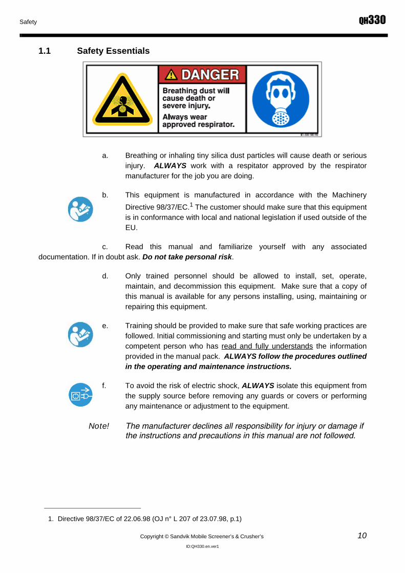
a. Breathing or inhaling tiny silica dust particles will cause death or seriousinjury. ALWAYS work with a respitator approved by the respiratormanufacturer for the job you are doing.
b. This equipment is manufactured in accordance with the MachineryDirective 98/37/EC.1 The customer should make sure that this equipmentis in conformance with local and national legislation if used outside of theEU.
c. Read this manual and familiarize yourself with any associateddocumentation. If in doubt ask. Do not take personal risk.
d. Only trained personnel should be allowed to install, set, operate,maintain, and decommission this equipment. Make sure that a copy ofthis manual is available for any persons installing, using, maintaining orrepairing this equipment.
e. Training should be provided to make sure that safe working practices arefollowed. Initial commissioning and starting must only be undertaken by acompetent person who has read and fully understands the informationprovided in the manual pack. ALWAYS follow the procedures outlinedin the operating and maintenance instructions.
f. To avoid the risk of electric shock, ALWAYS isolate this equipment fromthe supply source before removing any guards or covers or performingany maintenance or adjustment to the equipment.
Note! The manufacturer declines all responsibility for injury or damage if the instructions and precautions in this manual are not followed.
1. Directive 98/37/EC of 22.06.98 (OJ n° L 207 of 23.07.98, p.1)

QH330 Safety
11 Copyright © Sandvik Mobile Screener’s & Crusher’s
ID:QH330.en.ver1
1.2 Safety Signs and Labels
a. The term "DANGER" indicates a hazardous situation which, if notavoided, will result in death or serious injury.
b. The term "WARNING" indicates a hazardous situation which, if notavoided, could result in death or serious injury.
c. All electrical control boxes are labeled. Make sure that these labelsremain in place and are clearly visible at all times.
d. Other hazards identified within this manual may also be marked on theequipment with safety labels. Make sure that these safety labels remainin place and are clearly visible at all times.
1.3 Safety Hazards Pertaining to the Equipment
The following safety symbols may be posted on the equipment or contained in the manuals. You MUST observe all safety symbols, labels, and instructions.
a. MAKE SURE that safety instructions and safety labels attached to theequipment are ALWAYS complete and perfectly legible.
b. Keep safety instructions and safety labels clean and visible at all times.
c. Replace any illegible or missing safety instructions and safety labels withnew ones before operating the equipment.
d. Make sure replacement parts include safety instructions and labels.

Safety QH330
Copyright © Sandvik Mobile Screener’s & Crusher’s 12ID:QH330.en.ver1
1.3.1 Symbols for Mandatory Actions
Wear Safety Gloves Wear Eye Protection Wear Safety Helmet
Wear Safety Harness Wear Ear Protection Wear Safety Boots
Wear Close Fitting Overalls Wear Dust Mask Wear High Visibility Vest
Wear Respirator Disconnect Power Source From Supply
Switch Off and Lockout Equipment
Read the Manual

QH330 Safety
13 Copyright © Sandvik Mobile Screener’s & Crusher’s
ID:QH330.en.ver1
1.3.2 Symbols for Prohibited Actions
1.3.3 Hazard Symbols
No Climbing No Smoking Do Not Touch
No Open Flames Limited or Restricted Access Do Not Weld
Do Not Remove Safety Guard
Crushing Hazard - Hands Crushing Hazard - Feet Chemical Burn Hazard
Electrical Hazard Electrical Shock/Electrocution Hazard Emtanglement Hazard

Safety QH330
Copyright © Sandvik Mobile Screener’s & Crusher’s 14ID:QH330.en.ver1
1.3.4 Machine Legend Plate
Entanglement Hazard Falling Hazard Falling Load Hazard
Flammable Hazard Flying Material Hazard Hazardous or Poisonous Material Hazard
Lifiting Hazard Skin Injection Hazard Silica or Other Dust Hazard
Trip Hazard Magnet Hazard

QH330 Safety
15 Copyright © Sandvik Mobile Screener’s & Crusher’s
ID:QH330.en.ver1
1.4 Component Safety Features
a. DO NOT use this equipment if any safety guards or devices have beenremoved or are installed improperly.
b. Operating this equipment with any safety guards or devices which have
been removed or installed improperly could result in death or seriousinjury.
1.5 Features for Operator Safety
a. Safety features associated with this equipment have been assessed inaccordance with BS EN 954-1 to Category 3.
b. Emergency Stop buttons have been installed to prevent death or seriousinjury. Make sure that the Emergency Stop buttons are visible and arenot obstructed in any way.
c. The Emergency Stop circuit is a 24 V DC series circuit and hard wired toremove power from the ECU Engine management system and stop theengine. To avoid electric shock or cutting injury, you MUST wait atleast ten full seconds after activating the Emergency Stop to allowthe system to release its electrical charge.
d. You MUST study the detailed Safety Circuit diagram which is within thedrawing pack as an appendix to this manual.
e. Safety guards have been installed to prevent death or serious injury. DONOT remove, modify, or alter any safety guard. Make sure that all safetyguards are bolted down.
f. Steps, handrails, tread plates, and fixed guards are provided wherepersonnel are required to climb on the machine.
g. If for any reason other areas of the machine need to be accessed, risksMUST be assessed and appropriate safety measures taken.
1.6 Environmental Safety
To avoid unnecessary engine emissions, you MUST regularly service the machine as specified in the machine maintenance sections contained in this manual.

Safety QH330
Copyright © Sandvik Mobile Screener’s & Crusher’s 16ID:QH330.en.ver1
1.6.1 Hazardous Materials
a. Diesel spillages MUST be cleaned up immediately due to fire hazard.
b. ONLY use the lubricating oils recommended in the maintenanceschedule.
c. OBSERVE the COSHH information contained in the appendix to thismanual.
d. Local & National regulations MUST be observed when disposing ofwaste.
e. Improperly disposing of waste CAN THREATEN the environment andecology and is illegal.
f. MAKE SURE that all hazardous and replaced parts are disposed ofsafely and with minimum environmental impact.
1.6.2 Machine DisposalThis euipment MUST ONLY be disposed at a specialist machine breaker
• Potentially harmful waste used on this equipment includes items such as oil, fuel, coolant, filters, batteries, etc.
• DO NOT store harmful waste in food or beverage containers that may mislead someone into drinking from them, which could cause death or serious injury
• Use leak proof containers when draining fluids
• DO NOT pour waste onto the ground, down a drain or into any water source

QH330 Safety
17 Copyright © Sandvik Mobile Screener’s & Crusher’s
ID:QH330.en.ver1
1.7 Personal Protective Equipment (PPE)
1.7.1 Entanglement Hazards
1.7.2 Required Personal Protective EquipmentThis includes:
• Hard Hat
• Safety Glasses/Goggles
• Hearing Protection
• Dusk Mask
• Close Fitting Overalls
• Loose clothing, tools, jewelry, long hair, or body parts can get caught in running machinery, which will result in death or serious injury.
• ALWAYS wear correctly fitting (CE approved) personal protective equipment. Garments must be close fitting and no jewelry such as rings may be worn.
• DO NOT work close to machinery unless it is stopped

Safety QH330
Copyright © Sandvik Mobile Screener’s & Crusher’s 18ID:QH330.en.ver1
• Safety Boots
• Industrial Gloves
• High Visibility Vest or Jacket
• Respirator

QH330 Safety
19 Copyright © Sandvik Mobile Screener’s & Crusher’s
ID:QH330.en.ver1
1.8 Measure Noise Level
Ear protection must be worn if you are within 10 meters (approximately 33 feet) of the machine when the engine and other parts of the machine are running
The above diagram indicates the measured noise levels at a measured distance; i.e. 3 m (approximately 12 feet) - 96 dB indicates that at 3 meters the sound measured was 96 decibels. The readings were measured using a Castle GA101/701 meter with a calibration date of 20/06/06 and with all systems running situated on the factory assembly line. The product and local conditions will affect the noise levels.Vibration Levels
There are NO circumstances where an operator needs to be on or touching the machine when it is running
1.9 Vibration Levels
There are NO circumstances where an operator needs to be on or touching the machine when it is running.
96dB
90dB
86dB
94dB
1 Metre (3'3") Radius
2 Metre (6'6") Radius
112dB
99dB
3 Metre (9'9") Radius 96dB
88dB
92dB

Safety QH330
Copyright © Sandvik Mobile Screener’s & Crusher’s 20ID:QH330.en.ver1
1.10 Organisational Safety Measures
The following safety measures MUST be observed at all times:
• Understand the service procedure before doing work. Keep area clean and dry.
• NEVER lubricate, clean, service, or adjust machinery while it is moving.
• Allow the machinery to cool before performing any maintenance or adjustments.
• MAKE SURE that all parts are properly installed and are in good condition. Replace worn and broken parts IMMEDIATELY.
• Remove any build up of grease, oil and debris from equipment.
• Disconnect battery ground cable before making adjustments on electrical systems or welding on the equipment.
• During maintenance ONLY use the correct tool for the job.
• NEVER make any modifications, additions, or conversions which might affect safety without the manufacturer's approval.
• If clothing, tools, or any body parts become entangled in machinery, IMMEDIATELY disengage all power and operate controls to relieve pressure. Stop the engine and implement lockout procedures.
• If the equipment exhibits any unusual movement or sound, stop the equipment, lock out IMMEDIATELY, and report the malfunction to a competent authority or personnel.
1.11 Personnel Qualifications, Requirements and Responsiblities
a. All work involving the equipment MUST ONLY be performed by trained,reliable and authorized personnel only. Statutory minimum age limitsmust be observed.
b. Work on electrical system and its equipment MUST ONLY be carried outby a skilled electrician or by instructed persons under the supervision andguidance of a skilled electrician and in accordance with electricalengineering rules and regulations.
c. Work on the hydraulic system MUST ONLY be carried out by personnelwith special knowledge and experience of hydraulic equipment.

QH330 Safety
21 Copyright © Sandvik Mobile Screener’s & Crusher’s
ID:QH330.en.ver1
1.12 Safety Advice Regarding Specific Operational Phases
1.12.1 Standard Operation
a. Take the necessary steps to make sure that the equipment is used ONLYwhen it is in a safe and reliable state.
b. Operate the equipment ONLY for its designed purpose, and only if allguarding, protective, and safety devices, emergency shut-off equipment,sound proofing elements and exhausts, are in place and fully functional.
c. MAKE SURE that any local barriers are erected to stop unauthorizedentry to the equipment.
d. BEFORE starting the engine make sure that it is safe to do so.
1.12.2 Blockage or MalfunctionIn the event of material blockage, any malfunction or operational difficulty, stop the equipment and lockout immediately. Repair any defects or hazardous conditions immediately.
1.12.3 Unguarded Areas
a. Limit access to the equipment and its surrounds by erecting barrierguards to reduce the risk of other mechanical hazards, falling loads andejected materials.
b. Switch off and lockout the equipment before removing any safety devicesor guarding
• To avoid death or serious injury, ALWAYS keep your hands and other body parts away from pinch points on the machine.
• DO NOT reach into unguarded machinery.

Safety QH330
Copyright © Sandvik Mobile Screener’s & Crusher’s 22ID:QH330.en.ver1
1.13 Special Work, Including Equipment Maintenance and Repairs During Operation, Disposal of Parts, and Hazardous Materials
a. Observe the adjusting, maintenance, and service intervals set out in theoperating instructions, except where:
• Warning horns, lights, gauges, or indicators call for immediate action; OR
• Adverse conditions require more frequent servicing.
b. ALWAYS only use Original Equipment Manufacturer's ("OEM")recommended replacement parts and equipment.
c. Make sure that only properly trained personnel undertake these tasks.
1.13.1 Securing the Equipment Before Performing Maintenance
When undertaking maintenance and repair work, the equipment must first be made safe.
a. Switch off the engine using the ignition key. Switch off at isolation pointand remove the ignition key.
b. Implement lockout procedures.
c. Attach a hazard sign(s) to the equipment in appropriate positions to alertall personnel of potential hazards.
1.13.2 Maintenance Site ConditionsPrior to starting any maintenance work, MAKE SURE the equipment is positioned on stable and level ground and has been secured against inadvertent movement and buckling.
1.13.3 Replacement & Removal of Components
a. ALWAYS observe handling instructions itemized in this manual, theOriginal Equipment Manufacturer's manuals, or the spare parts suppliers'instructions.
b. NEVER allow untrained staff to attempt to remove or replace any part ofthe equipment.

QH330 Safety
23 Copyright © Sandvik Mobile Screener’s & Crusher’s
ID:QH330.en.ver1
c. The removal of large or heavy components without adequate liftingequipment is PROHIBITED.
d. To avoid the risk of accidents, individual parts and large assembliesbeing moved for replacement purposes should be carefully attached tolifting tackle and secured. ONLY use suitable and technically adequatelifting gear supplied or approved by Original Equipment Manufacturer.
e. NEVER work or stand under suspended loads.
f. KEEP AWAY from the feeder hopper and product conveyor discharge,where there is risk of serious injury or death from contact with ejecteddebris.
g. LIMIT ACCESS to the equipment and its surrounds by erecting barrierguards to reduce the risk of residual mechanical hazards, falling liftedloads, and ejected materials.
1.13.4 Climbing, Falling
a. Falling from and/or onto this equipment could result in death or seriousinjury.
b. NEVER climb on the equipment while it is in operation or use equipmentparts as a climbing aid.
c. ALWAYS keep the area around the equipment clear of debris and triphazards.
d. Beware of moving haulage and loading equipment in the vicinity of theequipment.
e. For carrying out overhead assembly work, ALWAYS use speciallydesigned or otherwise safety-oriented ladders and working platforms.
f. ONLY use walkways/platforms provided on the equipment. ALWAYSperform work from an approved, safe and secure platform.
g. When reaching any points 2m (approximately 6 feet) or more above theground level, ALWAYS use CE certified safety harness.
h. Keep all handles, steps, handrails, platforms, landing areas, and laddersfree from dirt, oil, snow and ice.

Safety QH330
Copyright © Sandvik Mobile Screener’s & Crusher’s 24ID:QH330.en.ver1
1.13.5 Safety Considerations During Maintenance
It is essential that you take the following steps to MAKE SURE you and others are safe.
a. During maintenance, RESTRICT ACCESS to essential staff only. Whereappropriate, erect barrier guards and post warnings.
b. The fastening of loads and instructing or guiding of crane operatorsshould be entrusted to qualified persons only.
c. The marshal providing instructions must be within sight or sound of theoperator and positioned to have an all around view of the operation.
d. ALWAYS make sure that any safety device such as locking wedges,securing chains, bars, or struts are utilized as indicated in these operatinginstructions.
e. Make sure that any part of the equipment raised for any reason isprevented from falling by securing it in a safe reliable manner.
f. NEVER work under unsupported equipment.
g. NEVER work alone.
1.13.6 Safety Considerations During Cleaning
a. This equipment MUST be isolated prior to cleaning.
b. DO NOT direct power washers near or into control boxes and devices.
c. After cleaning, examine all fuel, lubricant, and hydraulic fluid lines forleaks, loose connections, chafe marks and damage. Any defects foundMUST be repaired immediately.
1.13.7 Removal of Safety Devices and Guards
a. Prior to operation, all safety devices (control devices or guards)temporarily removed for set-up, maintenance or repair purposes MUSTbe refitted and checked immediately upon completion of the maintenanceand repair work.
b. To avoid serious personal injury or death, NEVER operate the equipmentwith safety devices or guards removed or unsecured.
c. ALWAYS report any defects regarding guards, safety devices or controldevices.

QH330 Safety
25 Copyright © Sandvik Mobile Screener’s & Crusher’s
ID:QH330.en.ver1
1.13.8 Surrounding Structures
a. This equipment MUST ONLY be operated in a position away frombuildings, permanent structures or high ground to eliminate the risk ofpersons falling onto the equipment or its surrounds.
b. Any temporary structures erected around the equipment MUST beremoved prior to operation.
1.13.9 Safety When Refueling
• Diesel fuel is flammable and creates a potential hazard which could result in death or serious injury.
• To avoid spillages use drip trays.
• ONLY refuel with diesel from approved storage and supply equipment.
• NEVER remove the filler cap or refuel with the engine running.
• NEVER add gasoline or any other fuels mixed to diesel due to increased fire or explosion risks and damage to the engine.
• Smoking is PROHIBITED when refueling or handling diesel fuel.
• DO NOT carry out maintenance on the fuel system near naked lights or sources of sparks, such as welding equipment.
• IMMEDIATELY clean up spilt fuel and dispose of correctly to minimize any environmental impact.

Safety QH330
Copyright © Sandvik Mobile Screener’s & Crusher’s 26ID:QH330.en.ver1
1.14 Specific Hazards
1.14.1 Electrical Energy
A. External Considerations and Hazards
When working with the equipment, maintain a safe distance from overhead electric lines. If overhead cables are in the vicinity, a risk assessment MUST be completed prior to operating the equipment
B. Machine - Electrical
1. Work on the electrical system or equipment MUST ONLY be carried outby a skilled and qualified electrician or by specially instructed personnelunder the control and supervision of such an electrician and inaccordance with applicable electrical engineering rules.
2. Before starting any maintenance or repair work, the power supply to theequipment MUST be isolated. Check the de-energized parts to makesure they do not have any power. In addition to insulating any adjacentparts or elements, ground or short circuit them to avoid the risk ofelectrical shock.
3. The electrical equipment is to be inspected and checked at regularintervals. Defects such as loose connections or scorched or otherwisedamaged cables MUST be fixed immediately.
4. Use ONLY original fuses with the specified current rating. Switch off theequipment IMMEDIATELY if trouble occurs in the electrical system.
5. This equipment is wired on a negative earth. ALWAYS observe correctpolarity.
Contact with overhead electric lines will cause death or serious injury.
If your equipment comes into contact with a live wire, you MUST:
• Vacate the area;
• Warn others against approaching and touching the equipment;
• Report the incident and have the live wire shut off.

QH330 Safety
27 Copyright © Sandvik Mobile Screener’s & Crusher’s
ID:QH330.en.ver1
1.14.2 Battery
a. ALWAYS disconnect battery leads before carrying out any maintenanceto the electrical system.
b. Recharge the battery in a well ventilated area.
c. The battery contains sulphuric acid, an electrolyte which can causesevere burns and produce explosive gases.
d. AVOID contact with the skin, eyes or clothing.
e. Smoking is PROHIBITED when maintaining the battery.
f. ALWAYS wear appropriate personal protective equipment.
1.14.3 Gas, Dust, Steam, Smoke and Noise
a. ALWAYS operate internal combustion engines outside or in a wellventilated area.
b. If, during maintenance, the equipment must be operated in an enclosedarea, MAKE SURE that there is sufficient ventilation or provide forcedventilation.
c. Observe the regulations in force at the respective site.
d. Dust found on the equipment or produced during work on the equipmentMUST NOT be removed by blowing with compressed air.
e. Dust waste MUST ONLY be handled by authorized persons. Whendisposing of dust waste, the material must be dampened, placed in asealed container and marked to ensure proper disposal.
f. Breathing or inhaling tiny silica dust particles will cause death or seriousinjury. ALWAYS work with a respitator approved by the respiratormanufacturer for the job you are doing.

Safety QH330
Copyright © Sandvik Mobile Screener’s & Crusher’s 28ID:QH330.en.ver1
1.14.4 Welding or Naked Flames
1.14.5 Hydraulic Equipment
a. Work on hydraulic equipment must be carried out by persons havingspecial knowledge and experience of hydraulic systems.
b. ALWAYS relieve pressure from the hydraulic system before carrying outany kind of maintenance or adjustment.
c. BEFORE carrying out any repair work, depressurize all system sectionsand pressure pipes (i.e. hydraulic system, compressed air system, etc.)requiring removal, in accordance with the specific instructions for the unitconcerned.
d. Hydraulic and compressed air lines MUST be laid and fitted properly.Make sure that no connections are interchanged. The fittings, lengthsand quality of the hoses MUST comply with the technical requirements.
e. ONLY fit replacement components of a type recommended by themanufacturer.
• Welding or naked flames on or around the equipment creates the risk of an explosion or fire, which could result in death or serious injury.
• AVOID all naked flames in the vicinity of this equipment.
• Welding, flame cutting and grinding work on the equipment MUST ONLY be carried out if this has been expressly authorized, as there may be a risk of explosion and fire.
• Before carrying out welding, flame cutting and grinding operations, clean the equipment and its surroundings from dust and other flammable substances and make sure the premises are adequately ventilated, as there may be a risk of explosion
• The battery MUST BE isolated.
• Splashed oil creates the risk of a fire, which could result in death or serious injury.
• Check all lines, hoses and screwed connections regularly for leaks or other damage.
• Repair damaged lines, hoses, or screwed connections IMMEDIATELY

QH330 Safety
29 Copyright © Sandvik Mobile Screener’s & Crusher’s
ID:QH330.en.ver1
f. ALWAYS practice extreme cleanliness when servicing hydrauliccomponents
1.14.6 Hazardous Substances
a. MAKE SURE that correct procedures are formulated to safely handlehazardous materials in strict accordance with the manufacturer'sinstructions and all applicable regulations by correctly identifying,labeling, storing, using and disposing of the materials.
b. A full list of Hazardous Substances associated with this equipment canbe found in the appendix of this document.
• Hydraulic fluid under pressure can penetrate the skin, which will result in death or serious injury.
• If fluid is injected under the skin, it must be surgically removed or gangrene will result. GET MEDICAL HELP IMMEDIATELY.
• ALWAYS use a piece of cardboard to check for leaks. DO NOT USE YOUR HAND

Safety QH330
Copyright © Sandvik Mobile Screener’s & Crusher’s 30ID:QH330.en.ver1
1.15 Safety Concerns
• TRIPPING or FALLING onto, into or near machine
• Crush, nip or PINCH injuries from moving parts
• Flying stones, rocks, projectiles or other injurious objects in vicinity of machine
• Contact with oil, hydraulic fluids or heated or caustic machine components
• Injuries arising from transporting, moving, dismantling, installation or repair of machine
This list is not exhaustive, and anyone in the vicinity of the QH330 should always be aware of the possibility of dangerous conditions that may exist, and of the potential for serious injuries resulting from such conditions.Anyone in the vicinity of the QH330 must ALWAYS:
• Comply with all safety recommendations set forth in the operations manual
• · Use appropriate safety equipment and appliances, including high visibility clothing, helmets, steel-toed shoes or boots with non-slip soles, gloves, protective eyewear, hearing protection
• · Switch off engine and remove ignition key when performing maintenance or adjustments. If alternate power is utilized to operate the machine, the System Immobilization Procedure set forth on the next page must be utilized.
This list is not exhaustive, and anyone in the vicinity of the QH330 should always utilize procedures and equipment that are appropriate to diminish or eliminate the risk of injuries.Anyone in the vicinity of the QH330 must NEVER:
• Wear loose or baggy clothing, neckties, scarves, untucked shirts or any other article that could become caught in moving parts of the machine.
• Climb on the machine – access points for the QH330 are marked, and other appropriate lifting equipment should be utilized as necessary. At no time should anyone climb on or around the QH330, as serious injuries or death may result.
This list is not exhaustive, and anyone in the vicinity of the QH330 should NEVER engage in any be-havior that compromises safety, renders the machine hazardous to persons, or otherwise increasesthe risk of injuries. Recommended safety procedures MUST ALWAYS be implemented and followed.
Anyone in the vicinity of the QH330 must be alert for potential dangers, including

QH330 Safety
31 Copyright © Sandvik Mobile Screener’s & Crusher’s
ID:QH330.en.ver1
1.15.1 Systems Immobilization ProcedureUtilize the procedure below whenever the QH330 is being operated under alternate power, or under any condition in which shutting off the engine and removing the ignition key does not completely cut power to the machine. Under such circumstances, to properly immobilize the QH330:
• Position all hydraulic controls in the neutral position
• Ensure that all supports and slide stops are securely fixed in position
• Switch off machine ignition and remove ignition key
• Lock power unit door panel with a padlock
• User must retain padlock key on his/her person during system immobilization
The above procedure MUST be utilized to safely immobilize the QH330 when it is under alternate power. Failure to utilize the above procedure may result in damage to the QH330, serious personal injuries or death.
1.15.2 Fundmental Safety Instructions And Product ApplicationThe QH330 has been specifically designed exclusively for separating and sizing products including quarry aggregates, topsoil and demolition aggregates. It is not designed for any other application, and should not be used for other applications. The QH330 may not be modified for use in non-aggregate sorting applications. Unauthorized modification of the machine, or use of the QH330 in applications other than indicated applications, will void all warranties provided by the manufacturer. The manufacturer assumes no responsibility for damage to the QH330, or for personal injuries, resulting from use of the QH330 in unauthorized applications. Risks associated with misuse of the QH330 rest exclusively with the end user.
The QH330 has been built to exacting manufacturing standards, and constructed in compliance with all applicable safety regulations and specifications. Used and maintained properly, the QH330 will provide end users with years of faithful service with minimal operational interruptions. Care must be exercised not to abuse the machine, or hinder its normal performance in any way. Failure properly to maintain and use the QH330 may result in damage to property including the machine itself, and may result in serious personal injuries or death.
ALL PERSONS OPERATING THE QH330 MUST REVIEW AND UNDERSTAND ALL INSTRUCTIONS AND SAFETY PROCEDURES SET FORTH IN THE OPERATIONS MANUAL, AND MUST FOLLOW ALL APPLICABLE PRECAUTIONS. Exclusive responsibility for proper training, operation and maintenance of the QH330 rests with the end user.
THE QH330 INCLUDES MOVING PARTS, WHICH MAY CREATE NIP OR PINCH POINTS ON OR AROUND THE MACHINE. NEVER PERMIT EXTREMITIES (ARMS,

Safety QH330
Copyright © Sandvik Mobile Screener’s & Crusher’s 32ID:QH330.en.ver1
1.15.3 Operational Safety Considerations
• Ensure that a copy of all operating instructions, including the Engine Operations Manual, is kept current and maintained with the QH330 at all times.
• Ensure that all operators comply with all applicable safety, health, environmental and workplace regulations.
• Operators MUST read and understand all operating instructions, and must always work utilizing indicated safety precautions and procedures.
• Operators must be subject to regular review and inspection, to ensure that all applicable safety, health, environmental and workplace regulations and instructions are observed during machine operation.
• Ensure that no loose clothing or accessories are worn on or near the machine. Long hair must be tied back or secured. Jewelry should never be worn in the vicinity of the QH330. Loose clothing, hair, jewelry and the like can become entangled in the moving parts of the QH330 and cause serious personal injuries or death.
• Operators and anyone in the vicinity of the QH330 must ALWAYS use appropriate protective equipment, including but not limited to hard hats, work gloves, eye protection, hearing protection, and safety vests.
• Operators MUST be familiar with and understand all warnings and labels affixed to the QH330. These warnings and labels should be observed scrupulously. Failure to do so may result in serious personal injuries or death. If warnings or labels are damaged or illegible, operators must notify management immediately.
• The QH330 includes many moving parts, and requires regular maintenance in order to operate efficiently, properly and safely. If any component of the machine, including any component related to safety (emergency stops, service brakes, etc.) begins to malfunction or exhibit irregular or unpredictable operation, notify management and your maintenance department immediately. Failure to correct a machine malfunction could result in serious personal injures or death.
• NEVER modify any part of the QH330 without express written authorization from the manufacturer. Unauthorized modification will void all warranties provided by the manufacturer, and the manufacturer assumes no responsibility for proper or safe operation of the QH330 following any unauthorized modification. Modification of the machine can result in serious personal injuries or death.
• ALWAYS ensure that the QH330 is maintained in accordance with the maintenance schedules set forth elsewhere in this manual.
• NEVER operate the QH330 if you have any concern that a safety feature of the machine is not or may not be operating properly.

QH330 Safety
33 Copyright © Sandvik Mobile Screener’s & Crusher’s
ID:QH330.en.ver1
• ALWAYS ensure, prior to operation of the QH330, that all safety devices and components, including but not limited to emergency stops, soundproofing elements and exhausts and fire suppression equipment, are in place and operational.
• Inspect the machine at least once per shift for damaged or defective components. If any damage is observed, or if the machine exhibits any malfunction or other unexpected operation, notify management and your maintenance department immediately. If necessary, down the machine and implement the Systems Immobilization Procedure set forth in this manual until repairs are completed. Special care should be taken regularly to inspect the machine’s return roller guards. Gaps between guards and rollers should not exceed 6mm, and conveyor belts and related parts should be maintained in strict compliance with the conveyor belt maintenance portion of this manual.
• If in doubt concerning the efficient, proper or safe operation of the QH330, contact a manufacturer’s representative.
1.15.4 Operator Selection And Qualification
• The QH330 should never be operated by persons without proper and complete training.
• Operators must read and understand the operations manual and all safety concerns prior to operation.
• Operators must be qualified legally to operate heavy equipment, i.e., be of age in the jurisdiction in which the QH330 is to be used, carry any required endorsements to licenses, etc.
• Training on the QH330 must only be carried out by qualified instructors, familiar with all operational and safety considerations. Do not attempt to operate the QH330 without having first completed appropriate training. Operation of the machine without first receiving adequate training may result in serious personal injuries or death.
• Maintain a list of individuals authorized to operate the QH330, and ensure that only those individuals operate the machine. NEVER entrust operation of the QH330 to any unauthorized persons.
• Components of the QH330 requiring specialized training to repair or maintain (electrical systems, hydraulics, etc.) should be repaired or maintained only by individuals with appropriate specialized training and qualifications.
1.15.5 Safety During Maintenance And Repair
• ALWAYS maintain the QH330 in accordance with the maintenance schedules set forth in this manual, unless conditions (e.g., illuminated warning lights, gauge or other indicator) mandate immediate or more frequent maintenance.

Safety QH330
Copyright © Sandvik Mobile Screener’s & Crusher’s 34ID:QH330.en.ver1
• Maintenance and repairs MUST be carried out by qualified personnel only. Work performed on the machine by unqualified persons may result in damage to the QH330, and may void warranties provided by the manufacturer. If in doubt concerning the methods or qualifications necessary to complete repairs or maintenance, contact the manufacturer.
• NEVER perform maintenance or repairs without first ensuring that the QH330 cannot be started. The Systems Immobilization Procedure outlined in this manual should always be utilized for this purpose. Inadvertent starting of the machine during the performance of maintenance or repairs can result in serious personal injuries or death.
• Maintenance and repairs should be performed in a secure area, and precautions MUST be taken to ensure that persons not involved in performance maintenance or repairs do not approach the machine. If maintenance or repairs in the field are necessary, the area around the QH330 should be secured and posted to minimize the risk of personnel approaching the vicinity of the machine.
• Dispose of all waste fluids, etc. properly and in accordance with applicable statutes and environmental regulations
• NEVER use the QH330 as a climbing aid. Maintenance and repairs should not be attempted or performed by climbing onto the machine. ALWAYS utilize safety platforms or lifts, and ALWAYS utilize appropriate safety harnesses and other safety equipment and appliances. Climbing onto or around the QH330 may result in serious personal injuries or death.
• When maintenance or repairs are completed, inspect all safety components of the machine, and ensure that all removable safety appliances are operational and/or replaced before the QH330 is returned to service.
• ALWAYS assure that the QH330 is positioned on stable and level ground, and has been secured against inadvertent movement, before beginning any maintenance or repairs.
• Heavy parts or assemblies should be moved into position for maintenance, repair or installation using only adequate and otherwise suitable lifting equipment. Loads should be carefully secured. NEVER work or stand under suspended loads.
• NEVER stand or work near the QH330’S grid, screenbox or discharge conveyors. Material unloaded, discharged or removed from these areas of the machine may cause serious personal injuries or death.
• NEVER weld or heat tire or wheel assemblies unless the tires have been de-pressurized. Inflated tires may explode if heated or contacted by welding equipment, resulting in serious personal injuries or death.

QH330 Safety
35 Copyright © Sandvik Mobile Screener’s & Crusher’s
ID:QH330.en.ver1
1.15.6 Special Considerations For Maintenance And Repair Of Electrical System
• Maintenance and repairs to the QH330’s electrical system must ALWAYS be performed by a qualified electrician or a skilled individual working under the supervision of a qualified electrician. Attempts to perform maintenance or repairs to the machine’s electrical system, without proper qualifications and/or supervision, may result in serious personal injuries or death.
• The Systems Immobilization Procedure set forth in this manual should be utilized during any maintenance or repair to the QH330’s electrical system.
• ALWAYS seal off the area where maintenance or repairs to the machine’s electrical system will be performed, including a posted warning of the dangers of electrocution. No unqualified persons should approach the vicinity of the QH330 during electrical system maintenance or repair.
• Before beginning maintenance or repair to the machine’s electrical system, ensure that the QH330 is properly immobilized and that there is no source of auxiliary or other power to the machine. ALWAYS disconnect the battery before beginning maintenance or repair work on the electrical system.
• ALWAYS use insulated tools. Failure to do so may result in serious personal injuries or death.
• The QH330 is grounded negatively. Procedures intended to ground positively-wired equipment may not render the machine safe for maintenance or repair work. When grounding is necessary, ALWAYS ground the feeder cable and short-circuit capacitors using a grounding rod before performing maintenance or repairs to the QH330’S electrical system.
• Use only approved manufacturer-supplied fuses and electrical components.
• ALWAYS maintain a safe distance between the QH330 and energized power lines. Do not attempt to operate the QH330, or perform maintenance or repairs, if the machine is in the proximity of energized power lines. Failure to keep the QH330 from energized power lines may result in serious personal injuries or death.
• ALWAYS assure that persons performing maintenance or repairs to the QH330’s electrical system have ready access to emergency shutoff switches, and can de-energize the machine immediately in the event that the QH330 becomes energized for any reason during maintenance or repairs.
• the QH330’s electrical system utilizes sufficient energy to seriously injure or kill persons coming into contact with energized electrical components. always ensure that the machine is completely de-energized before attempting maintenance or repairs.

Safety QH330
Copyright © Sandvik Mobile Screener’s & Crusher’s 36ID:QH330.en.ver1
1.15.7 Special Considerations For Maintenance Or Repair with Welding
Before welding;
• Disconnect LCD plug from the back of the Main Control Panel (See Photo below)
• Turn off Isolator Switch (See Photo Below)
• Disconnect Crusher Probe
1.15.8 Special Considerations For Maintenance Or Repair Of Hydraulic System
• Maintenance and repairs to the QH330’s hydraulic system must ALWAYS be performed by an experienced hydraulics technician or similarly-qualified individual. Attempts to perform maintenance or repairs to the machine’s hydraulic system, without proper qualifications and/or supervision, may result in serious personal injuries or death.
• The Systems Immobilization Procedure set forth in this manual should be utilized during any maintenance or repair to the QH330’s hydraulic system. ALWAYS ensure that the QH330’S hydraulic lifting components are properly supported during maintenance or repairs.
• Inspect all hoses, lines and screwed connections for leaks or other damage. Repair any leaking or damages hoses, lines or connections immediately.
• ALWAYS bleed and de-pressurize the QH330’s hydraulic lines before attempting maintenance or repairs to the machine. Failure to de-pressurize the hydraulic lines may result in serious personal injuries or death.
• The Hydraulic System Of The QH330 Utilizes Hydraulic Fluids, Oils And Other Caustic Substances, And Extreme Caution Should Be Exercised During The Performance Of Maintenance Or Repairs. Do Not Allow Hydraulic Or Other Fluids To Contact Unprotected Skin Or Eyes. Always Utilize Appropriate Safety Equipment And Appliances, Including Gloves And Eye Protection, When Performing
LCD
ISOLATOR

QH330 Safety
37 Copyright © Sandvik Mobile Screener’s & Crusher’s
ID:QH330.en.ver1
Maintenance Or Repairs To The QH330’s Hydraulic System. Failure To Observe Precautions May Result In Serious Injury Or Death.
1.15.9 Handling And Disposal Of Hazardous Components And Materials
• The QH330’S battery contains sulfuric acid, which can cause severe burns, and produces explosive gases. Inspect the machine’s battery regularly, and assure that it is properly connected and maintained. NEVER allow battery parts to come into contact with unprotected skin, eyes or clothing. NEVER attempt maintenance or repair to the QH330’S battery while the battery is connected.
• The QH330 includes an internal combustion engine, which produces exhaust fumes containing potentially harmful gases and particulates. Avoid starting the engine or operating for prolonged periods indoors. NEVER operate the machine’s engine in an area lacking adequate ventilation, whether indoors or outside.
• Prior to welding, cutting, or grinding, ALWAYS assure that dust and other flammable substances are removed from the work site. ALWAYS assure that the area where welding, cutting or grinding is conducted is properly ventilated. Failure to observe these precautions may increase the risk of explosion or fire, and may result in serious personal injuries or death.
• Keep flammable materials, chemicals, etc. away from the QH330 whenever screening or conveying flammable or hazardous products, such as coal etc. Maintaining flammable materials, chemicals, etc. in the presence of hazardous products may increase the risk of explosion or fire, and may result in serious personal injuries or death.
1.15.10 Warning Concerning Crystalline Silica And Similar Particulates. The QH330’S operation may produce dust containing crystalline silica or other potentially harmful particulates. ALWAYS utilize appropriate and properly-fitted safety equipment and appliances (e.g., respirators). DO NOT linger in areas where dust is produced, blown or otherwise found. NEVER inhale dust produced by the operation of the QH330.
Inhalation of crystalline silica dust is potentially harmful to human health, and may result in serious pulmonary disease or other deleterious chronic lung obstruction, serious personal injuries or death.
1.15.11 Special Considerations Concerning Dust Disposal. Always dispose of dust produced by the operation of the QH330 by applying water, placing dampened dust in a marked, sealed container, and removing it from the work site. NEVER disperse dust by blowing it; doing so may exacerbate dusty conditions in the proximity of the QH330, and may also cause dust to enter areas where unprotected persons may be working, creating an increased risk of injury or death. ALWAYS assure that dust is removed from clothing, boots, etc., before leaving the work site.

Safety QH330
Copyright © Sandvik Mobile Screener’s & Crusher’s 38ID:QH330.en.ver1
1.15.12 Special Considerations For Transport Of The QH330
• Do not attempt to transport the QH330 utilizing a vehicle not specified for hauling at least the listed gross weight of the machine. Failure to use transportation with sufficient hauling capacity may result in damage to the QH330 and the hauling vehicle, and may result in serious personal injuries or death.
• ALWAYS observe applicable local and national regulations concerning the transportation of heavy equipment. Ensure that all appropriate permits, licenses and endorsements are obtained and maintained before transporting the QH330.
1.15.13 Special Considerations For Maintenance Or Repair To The QH330’s Tires
• Only experienced and suitably qualified personnel should attempt to change or repair the machine’s tires.
• Tires should be inflated using a device that permits inflation at distance from the tire, to decrease the risk of injury in the event of a tire rupture or explosion.
1.15.14 Location Of Emergency Stops On QH330There are four E-Stops on the QH330 and one on the remote control.

QH330
Copyright © Sandvik Mobile Screener’s & Crusher’s 39ID:QH330.en.ver1
2.0 Technical and Transport

Technical and Transport QH330
Copyright © Sandvik Mobile Screener’s & Crusher’s 40ID:QH330.en.ver1
2.1 Technical Information
Machine: Mobile Cone Crushing UnitType: QH330 Total Weight: 37,500Kg (82,700lbs approx) (without options)Transport Width: 2.80mTransport Length: 14.5mTransport Height: 3.4m
2.1.1 Standard Features
Secondary Sandvik CH430 Cone Crusher with Hydraulic CSS Adjustment using Hydroset SystemAll in Direct Feed which Produces High Quality Final AggregatesTotal Access for Cone Maintenance from above due to Hydraulic Folding Feed ConveyorMicro Control SystemHydrostatic Crusher DriveTramp Metal Relief SystemLevel Monitoring fitted in Crusher to Control Feed Rate and to Insure Core is Choke FedDust SuppressionMetal Detector
2.1.2 Options
Radio Controlled Tracks Remote Diesel PumpDust Suppression Water PumpBelt ScaleA Choice of Crushing Chambers to Suit Application

QH330 Technical and Transport
41 Copyright © Sandvik Mobile Screener’s & Crusher’s
ID:QH330.en.ver1
2.1.3 Transport and Working Dimensions

Technical and Transport QH330
Copyright © Sandvik Mobile Screener’s & Crusher’s 42ID:QH330.en.ver1

QH330 Technical and Transport
43 Copyright © Sandvik Mobile Screener’s & Crusher’s
ID:QH330.en.ver1
2.2 Indentification of Main Units
A Main ConveyorB Power UnitC Cone CrusherD Feed ConveyorE Feed HopperF Hydroset TankG Cone Control BoxH Lubrication TankI TracksJ Diesel TankK Main Control Box
L Hydraulic Tank
2.3 Specification of Main Units
2.3.1 Feeder HopperWidth 2500 mm (8ft 2’’)Length 2450 mm (8ft)Capacity 5m3(6.5 cubic yards)
A
B
CD
E
LHS
FRONTFGH
L
REAR
RHS
K
J
I
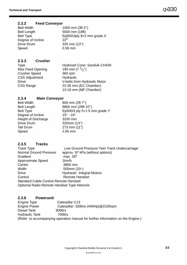
Technical and Transport QH330
Copyright © Sandvik Mobile Screener’s & Crusher’s 44ID:QH330.en.ver1
2.3.2 Feed ConveyorBelt Width 1000 mm (3ft 3’’)Belt Length 5500 mm (18ft)Belt Type Ep500/3ply 8+2 mm grade X Degree of Incline 220
Drive Drum 320 mm (13’’)Speed 0.58 m/s
2.3.3 CrusherType Hydroset Cone: Sandvik CH430Max Feed Opening 190 mm (7 1/2’’)Crusher Speed 360 rpmCSS Adjustment HydraulicDrive V-belts from Hydraulic MotorCSS Range 22-35 mm (EC Chamber)
13-19 mm (MF Chamber)
2.3.4 Main ConveyorBelt Width 800 mm (2ft 7’’)Belt Length 8800 mm (28ft 10’’)Belt Type Ep500/3 ply 5+1.5 mm grade Y Degree of Incline 15° - 24°Height of Discharge 3200 mmDrive Drum 320mm (13’’)Tail Drum 273 mm (11”)Speed 2.65 m/s
2.3.5 TracksTrack Type Low Ground Pressure Twin Track UndercarriageNormal Ground Pressure approx. 97 kPa (without options)Gradient max. 28o
Approximate Speed 1km/hCentre 3850 mmWidth 500mm (20,,)Drive Hydraulic Integral MotorsControl Remote HandsetStandard Cable Control Remote HandsetOptional Radio Remote Handset Type Hetronic
2.3.6 PowerunitEngine Type Caterpillar C13Engine Power Caterpillar- 328Kw (440Hp)@2100rpmDiesel Tank 900ltrsHydraulic Tank 700ltrs(Refer to accompanying operation manual for further information on the Engine.)

QH330
Copyright © Sandvik Mobile Screener’s & Crusher’s 45ID:QH330.en.ver1
3.0 Product Overview

Product Overview QH330
Copyright © Sandvik Mobile Screener’s & Crusher’s 46ID:QH330.en.ver1
3.1 Product Overview
This section has been designed to familiarise the user with the various controls and functions of theindividual components that make up the QH330.
Please ensure you read this section carefully.
The sections dealing with the various components of the machine will be cross-referred to in othersections of this Operations and Spares Manual.
3.1.1 Major Components
a. ower unit - the power unit is fully detachable and lockable. it is the source of all the hydraulic andelectrical power used to power all functions of the machine.
b. main control box - the engine control panel is located here.
c. feed hopper - the raw material is initially fed into this hopper.
d. FEED Conveyor - the raw material is initially fed into this hopper.
e. CONE Crusher - the raw material from the feeder conveyor is crushed in the cone crusher.
f. Cone Control Box - This controls the functions of the cone crusher itself including the lubrication andhydroset tanks.
g. Hydroset Tank - This tank stores 40L hydroset oil.
h. Lubrication Tank - This tank stores 150L lubrication oil.
i. Main Conveyor - The main conveyor carries the processed material away from the cone crusher.
j. Diesel Tank - This tank stores 900L diesel.
k. Hydraulic Tank - This tank stores 700L hydraulic oil.
l. Tracks - For machine manoeuvrability.
I
A
ED
C
LHS
FRONTGFH
K
REAR
RHS
B
J
L

QH330 Product Overview
47 Copyright © Sandvik Mobile Screener’s & Crusher’s
ID:QH330.en.ver1
3.1.2 Identification and Operation of the QH330 Controls
There are three sets of controls on the QH330:
1. The main control panel which is located on the right hand side of themachine in the lockable control box.
2. The double hydraulic control bank at the front right hand side of themachine.
3. The remote control which can be found in the control box upon delivery ofthe machine.
Main Control Panel
Remote Control
Double HydraulicControl Bank

Product Overview QH330
Copyright © Sandvik Mobile Screener’s & Crusher’s 48ID:QH330.en.ver1
3.1.3 Main Control Panel
The main control panel, as shown consists of the following;
• Ignition - This control is used to start and stop the machine.
• Emergency Stop - When pressed, the engine will stop
• Display Panel- This panel is used to operate and observe the functions of the machine.
All settings and procedures are accessed via the numbered buttons on this display panel. To enter
any command or access a new sub-menu screen, simply press the relevant button.
To exit a particular sub-menu and go back one level, press the ESC button or a return button whichwill be highlighted.
Active programs/options are identified to the user by a green symbol.
EmergencyStop
Ignition

QH330 Product Overview
49 Copyright © Sandvik Mobile Screener’s & Crusher’s
ID:QH330.en.ver1
3.1.4 Main Operations Menu

Product Overview QH330
Copyright © Sandvik Mobile Screener’s & Crusher’s 50ID:QH330.en.ver1
1. Auto/Manual Run Mode Selection
Auto - software utilises pre-determined settings to start the machine and functionality to commenceoperation.
Manual - this mode allows the operator to select particular functions and start each operation inturn.
2. Tracking Mode Operation
Tracking operation can vary between manual tracking and radio remote operation.
3. Service Log & Fault Log
Logging and viewing service history, viewing fault log.
4. No Action
5. Engine Status
Displays engine information e.g. running hours, engine speed, etc.
6. Maintenance
This screen can only be accessed via a password and is used to run machine features individuallyand set up machine run parameters.
7. Fuelling Lift Pump (optional)
Switches engine refuelling transfer pump on/off
8. Work Lamps (optional)
Switches work lamps on/off

QH330 Product Overview
51 Copyright © Sandvik Mobile Screener’s & Crusher’s
ID:QH330.en.ver1
3.1.5 Hydraulic Controls
The Double Hydraulic Control Bank
This hydraulic control bank, is located at the fron of the machine on the right hand side.
The controls have the following functions;
Main Conveyor Lift (HC A) -
Pull this lever up to raise the main conveyor tail section.
Push it down to lower the main conveyor tail section.
Feed Conveyor Lift (HC B) -
Pull this lever up to raise the feed conveyor.
Push it down to lower the feed conveyor.
NEUTRAL
UP
DOWN
A B

Product Overview QH330
Copyright © Sandvik Mobile Screener’s & Crusher’s 52ID:QH330.en.ver1
3.1.6 Remote Control Unit
The remote control has two functions:
1. to track the machine
2. to start/stop the feeder
There are several controls on the remote unit:
• A joystick for each track (LH/RH) used to drive the tracks either forward or back. The diagram below shows the direction of forward travel. The track joysticks control the track speed proprtionally.
• An E-stop button that, if pressed will shut off the engine.
• A On/Off toggle switch for the feeder for operator convenience.
• An on-off key switch (A) that is used to turn the remote unit on or off.
• A green push button (B) that must be pressed to activate the remote.
FORWARD
BACK
FRONT
LEFT
RIGHT

QH330 Product Overview
53 Copyright © Sandvik Mobile Screener’s & Crusher’s
ID:QH330.en.ver1
3.1.7 Hydraulics
The hydraulic systems are used to transmit power through all hydraulic motors and cylinders.
For long life under adverse operating conditions hydraulic systems are used extensively on the ma-chine. In the interests of continuous production it is essential that all of these systems are regularlymaintained with meticulous care and attention in order to avoid contamination. Contamination willhave an adverse impact on the operation of the machine.
The individual components of the HYDRAULIC TANK
HT 1 Temperature SensorHT 2 Hydraulic Oil Level SensorHT 3 Hydraulic Oil Level IndicatorHT 4 Breather FilterHT 5 Tank Access PanelHT 6 Return Line FiltersHT 7 Suction FiltersHT 8 Drain Bung
4 5 6
78
1
2
3

Product Overview QH330
Copyright © Sandvik Mobile Screener’s & Crusher’s 54ID:QH330.en.ver1
3.1.8 Lubrication System
The lubrication system in the QH330 is used to lubricate the bearings in the cone crusher itself.
In the interests of continuous production it is essential that the lubrication system is regularly main-tained with meticulous care and attention in order to avoid contamination. Contamination will havean adverse impact on the operation of the QH330.
The individual components of the LUBRICATION TANK (as shown in the diagram above)
LT 1 Anti-loose FastenerLT 2 Lubrication Oil Level Indicator & Level SensorLT 3 Suction FilterLT 4 Drain BungLT 5 Filter TrayLT 6 Tank Access Panel
34
6
2
1
5

QH330 Product Overview
55 Copyright © Sandvik Mobile Screener’s & Crusher’s
ID:QH330.en.ver1
3.1.9 Hydroset System
The hydroset system in the QH330 is used to change the cone crusher settings.
In the interests of continuous production it is essential that the hydroset system is regularly main-tained with meticulous care and attention in order to avoid contamination. Contamination will havean adverse impact on the operation of the QH330.The individual components of the HYDROSETTANK (as shown in the diagram above)
HT 1 Filler CapHT 2 Tank Access PanelHT 3 Suction FilterHT 4 Drain BungHT 5 Hydroset Oil Level Indicator & Level Sensor
1 2
34
5

Product Overview QH330
Copyright © Sandvik Mobile Screener’s & Crusher’s 56ID:QH330.en.ver1
This Page is intentionally left blank

QH330
Copyright © Sandvik Mobile Screener’s & Crusher’s 57ID:QH330.en.ver1
4.0 Commissioning and Shut Down

Commissioning & Shut Down QH330
Copyright © Sandvik Mobile Screener’s & Crusher’s 58ID:QH330.en.ver1
4.1 Commissioning & Shutdown Safety
! THINK SAFETY !
Please refer to the Safety Section of this manual for additional information on safe operation, main-tenance and repair of the machine. To ensure maximum safety, ALWAYS read this section carefullyBEFORE carrying out any work on the equipment or making any adjustments. Do not attempt op-eration, maintenance or repair without first consulting all pertinent safety information.
4.1.1 What Are The Hazards And Dangers?
• Trips and Falls - falls from Height• Nip or Crush Injuries - Part of or Whole Bodies• Being Struck by Falling Objects• Striking against fixed objects• Hydraulic Systems – High Pressure Oil Will Penetrate the Body• Injury from Contact With Moving Parts or Machinery• Manual Handling Injury – Lifting and Moving Parts or Components
4.1.2 Who is at Risk
• Operators, Maintenance Personnel,• Subcontractors and Anybody Else in the Vicinity of the Machine
4.1.3 Are Precautions Adequate?
• Always refer to the Safety Section in the Operation Manual• Use the Correct Personal Protection Equipment:
High Visibilty ClothingSafety HelmetSafety FootwearGlovesSafety GlassesEar Protection
• Do not wear loose or baggy clothing which could become caught in the moving parts of the machine
• Do not Climb on The Machine – Always use the Access Points and Platforms or Other Access Equipment as Required
4.1.4 When carrying out maintenace or adjustmenta. Either Switch off enginer and remove ignition key
OR Implement the Sytem Immobilisation Procedure if other power supply is used.
b. Always Relieve Pressure from the hydraulic system

QH330 Commissioning & Shut Down
59 Copyright © Sandvik Mobile Screener’s & Crusher’s
ID:QH330.en.ver1
4.2 Commissioning
Read And Follow All Instructions Concerning Set Up Of Your QH330. Failure To Do So May ResultIn Damage To The Machine, May Result In Serious Injury Or Death, And May Void Manufacturer’sWarranties.
The Following Instructions Assume Transport Of The QH330 From A Low Loader-type Vehicle InClose Proximity To The Job Site; If The Machine Is Transported In A Different Manner, Contact TheManufacturer For Additional Set Up Instructions.
IT IS RECOMMENDED THAT SET UP OF THE QH330 BE CARRIED OUT BY A REPRESENTA-TIVE OF SANDVIK MOBILE SCREENING & CRUSHING LTD, OR BY A QUALIFIED REPRESENT-ATIVE OF THE DEALER.
4.2.1 Preparation for Machine STARTUP
• SURFACE PREPARATION: The QH330 is designed for operation on a solid, level surface. It is important that the machine isplaced on solid ground that must be capable of carrying the weight of the machine and that the ma-chine is placed on level ground. The machine should be level to within 2 degrees from left to right.An appropriate site must be identified prior to delivery and unloading of the machine.
• VISUAL INSPECTION: Before powering up the engine a visual inspection of the QH330 should be performed. Any damagenot noted prior to startup remains the responsibility of the end user. Inspection should ensure that(1) all safety equipment is installed and functioning properly; and (2) any loose items delivered withthe QH330 have been secured or removed from the machine.

Commissioning & Shut Down QH330
Copyright © Sandvik Mobile Screener’s & Crusher’s 60ID:QH330.en.ver1
4.2.2 Start-up Sequence For Tracking Machine a. Observe all safety warnings.
b. Ensure all Emergency Stops are released and that the switch on the remote control is alsoturned off.
c. Turn on the ignition switch (but do not start the engine) and check the following screens areshown respectively (Fig. 4.1). It should take a few seconds. If there is a problem it will be shownon the screen.
d. Now start the machine, turn the ignition switch fully clockwise. The siren will sound & beacon willflash for 7 seconds before the engine will start. (If engine turns and does not start, turn off theignition and wait for a few seconds, then try and start again.)
e. Switch on the tracking mode by pushing button 2 as shown above (Fig. 4.1). The screen asshown below (Fig. 4.2) will appear.
Track Mode Activate( Fig.4.1 )
( Fig. 4.2 )
Engine RPM
Raise and Lower
Radio Receiver Activate

QH330 Commissioning & Shut Down
61 Copyright © Sandvik Mobile Screener’s & Crusher’s
ID:QH330.en.ver1
f. Turn the transmitter to the On ‘I’ and wait for the green light to flash consistently after a fewseconds as shown below (Fig. 4.3 & 4.4)
g. Switch on the radio receiver by pushing button 1 as shown on the screen (Fig. 4.2). This willhighlight the aeriel symbol.
h. Activate the radio transmitter by pushing the green button as shown below (Fig. 4.5). The sirenwill sound & beacon flash. It will take 7 seconds before the radio transmitter is ready to use.
i. The machine will track using the two joysticks.
j. Engine RPM can be adjusted up and down to aid tracking using the buttons as shown in(Fig. 4.2).
For full explanation and location of controls refer to Product Overview Section
RemoteControl
( Fig. 4.3 )
Wait forGreen lightto flash
( Fig. 4.4 )
on ‘I’
Activate Remote
( Fig. 4.5 )
Warning
BEFORE MOVING THE MACHINE VISUALLY CHECK THE AREA AROUND THE MACHINE TO ENSURE THERE IS
NO ONE STANDING IN A DANGEROUS POSITION

Commissioning & Shut Down QH330
Copyright © Sandvik Mobile Screener’s & Crusher’s 62ID:QH330.en.ver1
4.2.3 Machine Set-Up
a. Remove transport pins from the crusher assembly (See photo below).
b. Remove the pins from the transport position on the feed conveyor supports on both sides (Seephoto below).
c. With the engine running and the tracking mode screen still activated press button 3 to activatethe auxiliary controls as shown below
WarningBEFORE ATTEMPTING TO SET-UP THE MACHINE
ENSURE THAT THE OPERATOR HAS READ AND FULLY UNDERSTOOD THIS AND ALL THE PRECEEDING SEC-
TIONS IN THE MANUAL.
ActivateAuxiliaryControls

QH330 Commissioning & Shut Down
63 Copyright © Sandvik Mobile Screener’s & Crusher’s
ID:QH330.en.ver1
d. Raise the feed conveyor by pulling up HC B on the double hydraulic control bank (See photobelow)..
Re-insert the pins into the new position on the feed conveyor supports on both sides (See photobelow

Commissioning & Shut Down QH330
Copyright © Sandvik Mobile Screener’s & Crusher’s 64ID:QH330.en.ver1
4.3 Operating the QH330
Before Commencing general operation it is recommended that the following checks are carried out.
• ENGINE OIL LEVEL• HYDRAULIC OIL LEVEL• DIESEL LEVEL• VISUAL INSPECTION: ensure that there are no loose bolts and no loose guards and
all safety devices such as EMERGENCY SHUT OFFS are fully functional
4.3.1 Start-up Sequence For Running the Crushera. Observe all safety warnings
b. Ensure all Emergency Stops are released and that the switch on the remote control is also turnedoff.
c. Turn on the ignition switch (but do not start the engine) and check the following screens areshown respectively (Fig. 4.7). It should take a few seconds. If there is a problem it will be shownon the screen.
d. Select Auto/Manual Run by pressing button 1 as shown above (Fig. 4.7)
WarningBEFORE ATTEMPTING TO SET-UP THE MACHINE ENSURETHAT THE OPERATOR HAS READ AND FULLY UNDERSTOODTHIS AND ALL THE PRECEEDING SECTIONS IN THE MANUAL.
AUTO MANUALRUN SELECTION
(FIG. 4.7)

QH330 Commissioning & Shut Down
65 Copyright © Sandvik Mobile Screener’s & Crusher’s
ID:QH330.en.ver1
4.4 Auto Run Mode
Select Auto Run by pressing button 1 on the Run Menu Screen as shown below (Fig. 4.8). Selectingthis option allows the software to utilise pre-determined settings to operate the machine. The autorun screen will appear as shown in (Fig. 4.9).
AutoRun Screen
(Fig. 4.8)
Auto runSelection
Engine CSS Position
CrusherDrive Pressure
Crusher speed
HydrosetPressure
Lubricatin OilTemperature
Speed

Commissioning & Shut Down QH330
Copyright © Sandvik Mobile Screener’s & Crusher’s 66ID:QH330.en.ver1
The Functions availble for selection on the AutoRun screen are as follows
4.4.1 CSS Adjustment
The adjustment to the CSS can be made at any stage when in the auto screen mode by pressingbutton 1 as shown in (Fig. 4.11)
The CSS adjustment feedback will illuminate when CSS is opening or closing as shown in (Fig. 4.12).
4.4.2 Calibratio
Button 1
ON/OffCSS adjustment
CSS AdjustmentOPEN
CSS AdjustmentCLOSE
(Fig. 4.11)
CSS Adjustmentfeedback
(Fig. 4.12)
Button 2Auto Calibration
to recalibrate the crusher “0mm”position press button 2.

QH330 Commissioning & Shut Down
67 Copyright © Sandvik Mobile Screener’s & Crusher’s
ID:QH330.en.ver1
4.4.3 Auto Start Up Sequence
The machine will begin the Auto Start Up Sequence when button 5 is pressed as shown in (Fig. 4.14).
If no machine faults have been detected the crusher lubricating oil pump switches on. (See Mainte-nance section for details on fault warnings)
If the lubrication oil is not at operating temperature the lubrication heater will be switched on and willbe indicated by the symbol in (Fig. 4.14).
As the lubrication oil temperature increases the engine speed will increase in set stages. The engineramps up to 1400rpm.
When the lubricating oil reaches its preset temperature (20oC) the siren will sound for 7 seconds andthen the main conveyor will start.
The crusher will start to ramp up to its set speed and the engine will go to full speed.
After the crusher reaches its set speed and CSS position the feeder will start.
The Machine Feedback (see (Fig. 4.14)) indicates when each component is switched on by changingfrom red to green.
ESC - When all the buttons are in the off position press ESC to backup to previous screen.
THE CRUSHER IS NOW FULLY OPERATIONAL AND READY TO RECEIVE MATERIAL. ITSHOULD BE NOTED THAT ONLY SUITABLY SIZED MATERIAL SHOULD BE LOADED INTO THEFEEDER TO AVOID BLOCKAGE.
IN THE EVENT OF AN ACCIDENT OR ANY SERIOUS PROBLEM WITH THE MACHINE YOUSHOULD PRESS THE NEAREST EMERGENCY STOP BUTTON
PLEASE REFER TO SAFETY SECTION FOR LOCATION OF EMERGENCY STOPS
Button 5Auto Start
Lubrication Heater
( fig. 4.14)

Commissioning & Shut Down QH330
Copyright © Sandvik Mobile Screener’s & Crusher’s 68ID:QH330.en.ver1
4.4.4 Auto Stop Sequence
Before shutting down the machine it is important that the QH330 is empty. Run the QH330 for ap-proximately 5 minutes with no load to ensure it is completely empty.
The Auto Stop Sequence begins when button 6 is pressed as shown in (Fig. 4.15).
The feeder shuts down.
When the crusher drive pressure falls below a set pressure the crusher will stop within a set time.
WarningKEEP AWAY FROM THE FEEDER AREA, WHERE THERE IS RISKOF SERIOUS INJURY OR DEATH DUE TO REJECTED MATERIALAND DANGER FROM OTHER HEAVY MACHINERY WORKING IN
THE AREA. ONLY FULLY TRAINED OPERATORS ENGAGED IN LOADING THE MACHINESHOULD BE IN THIS AREA..
WarningKEEP AWAY FROM THE CONVEYOR BELTS, WHERE THERE ISRISK OF SERIOUS INJURY OR DEATH DUE TO REJECTED MA-TERIAL AND AGAIN DANGER FROM OTHER HEAVY MACHINE-
RY WORKING IN THE AREA. ONLY FULLY TRAINED OPERATORS ENGAGED INCOLLECTING PROCESSED MATERIAL FROM THE STOCKPILES SHOULD BE IN THISAREA.
Button 6Auto Stop

QH330 Commissioning & Shut Down
69 Copyright © Sandvik Mobile Screener’s & Crusher’s
ID:QH330.en.ver1
4.4.5 Manual Run Mode
Select Manual Run by pressing button 2 on the Run Menu Screen as shown in Fig 4.16. Slecting thisoption allows the operator to slect particular functions and start each operation in turn. The manualRun screen will appear as shown in Fig 4.17
Press Button 1 to enter Manual start Up
Button 2Manual Run Selection
(fig. 4.17)
Button 1Manual Run start up
(fig. 4.17)
selection

Commissioning & Shut Down QH330
Copyright © Sandvik Mobile Screener’s & Crusher’s 70ID:QH330.en.ver1
4.4.6 Manual Start Up
The Manual Start Up Screen appears as shown in (Fig. 4.18)
The following functions can be actioned to start up the machine;
Button 2Main Conveyor - Press to start main conveyor. There is a 7 second delay before the main conveyorstarts.
Button 3Crusher - Press to start crusher sequence. Crusher will not start until main conveyor is running andlubricating oil is at the correct level and temperature.
Button 6Feed Conveyor - Press to start and select feed conveyor speed. See next page for more details onfeed conveyor adjustment.
Arrow Left Button - To increase engine speed. If crusher has been selected and lubrication oil isnot above 20oC engine speed will only rise in set stages.
Arrow Right Button - To decrease engine speed.
4.4.7 Feed Conveyor Adjustment
When the feed conveyor option (button 6 on the manual start up screen (Fig. 4.18)) is pressed thefeed adjust buttons are displayed as shown in (Fig. 4.19). Buttons 7 & 8 are used to increase/de-crease the speed respectively. The hopper level control sensor is disabled in the manual mode.
Note! Note:The operator cannot escape from this screen until all the buttons are in the off position and the engine is at idle speed.
Button
Button
Button
Arrow Right ButtonArrow Left Button
Button 7 Increase Speed
Button 8 Decrease Speed

QH330 Commissioning & Shut Down
71 Copyright © Sandvik Mobile Screener’s & Crusher’s
ID:QH330.en.ver1
4.4.8 Manual Stop Sequence
Before shutting down the machine it is important that the QH330 is empty. Run the QH330 for ap-proximately 5 minutes with no load to ensure it is completely empty.
To manually shut down the QH330 follow this sequence referring to (Fig 4.18);
Stop the feed conveyor by selecting button 6.
Stop the crusher by selecting button 3. The engine will ramp down to idle speed.
Stop the main conveyor by selecting button 2
4.4.9 Machine Shut Down
Before shutting down the machine it is important that the QH330 is empty. Run the QH330 for ap-proximately 5 minutes with no load to ensure it is completely empty.
a. Stop the machine functions accordingly as described for Auto Stop ( page 71) or Manual Stop (page 74).
b. Use ESC button to return to Main Menu Screen.
c. Remove the pins from the working position on the feed conveyor supports on both sides (Seephoto below).
d. Select button 3 on the Tracking Mode Screen to activate the auxiliary controls as shown in (Fig.4.20)
Fig 4.20
Activate Auxiliary Controls

Commissioning & Shut Down QH330
Copyright © Sandvik Mobile Screener’s & Crusher’s 72ID:QH330.en.ver1
e. Lower the feed conveyor by pulling down HC B on the double hydraulic control bank (See photobelow).
f. Re-insert the pins into the transport position on the feed conveyor supports on both sides (Seephoto below)
g. Insert transport pins into the crusher assembly (See photo below).
h. Switch the ignition off

QH330 Commissioning & Shut Down
73 Copyright © Sandvik Mobile Screener’s & Crusher’s
ID:QH330.en.ver1
4.4.10 Emergency Stop
IN THE EVENT OF AN ACCIDENT OR ANY SERIOUS PROBLEM WITH THE MACHINE YOUSHOULD PRESS THE NEAREST EMERGENCY STOP BUTTON
PLEASE REFER TO SAFETY SECTION FOR LOCATION OF EMERGENCY STOPS
EMERGENCY STOP
• Engage the nearest emergency stop, the location of which can be found in the safety section.
• Switch off the engine and remove the ignition key.
• Implement the lockout procedure.
• Only when the machine is fully switched off, should an attempt be made to solve the problem.
RESTART AFTER EMERGENCY STOP
• Ensure that the problem has been solved
• Ensure that all personnel are clear of the machine.
• Ensure that all safety devices are correctly fitted and fully functional.
• Release all emergency stops.
• Re-start the engine in accordance with the correct procedure.

Commissioning & Shut Down QH330
Copyright © Sandvik Mobile Screener’s & Crusher’s 74ID:QH330.en.ver1
This Page is intentionally left blank

5.0 Operation

Operation QH330
Copyright © Sandvik Mobile Screener’s & Crusher’s 76ID:QH330.en.ver1
5.1 Section under construction

QH330
Copyright © Sandvik Mobile Screener’s & Crusher’s 77ID:QH330.en.ver1
6.0 Maintenance

Maintenance QH330
Copyright © Sandvik Mobile Screener’s & Crusher’s 78ID:QH330.en.ver1
6.2 Maintenance Safety
! THINK SAFETY !
Please refer to the Safety Section of this manual for additional information on safe operation, maintenance and repair of the machine. To ensure maximum safety, ALWAYS read this section carefully BEFORE carrying out any work on the equipment or making any adjustments. Do not attempt operation, maintenance or repair with out first consulting all pertinent safety information.
6.2.1 What Are The Hazards And Dangers?
• Trips and Falls - falls from Height• Nip or Crush Injuries - Part of or Whole Bodies• Being Struck by Falling Objects• Striking against fixed objects• Hydraulic Systems – High Pressure Oil Will Penetrate the Body• Injury from Contact With Moving Parts or Machinery• Manual Handling Injury – Lifting and Moving Parts or Components
6.2.2 Who is at Risk
• Operators, Maintenance Personnel,• Subcontractors and Anybody Else in the Vicinity of the Machine
6.2.3 Are Precautions Adequate?
• Always refer to the Safety Section in the Operation Manual• Use the Correct Personal Protection Equipment:
High Visibilty ClothingSafety HelmetSafety FootwearGlovesSafety GlassesEar Protection
• Do not wear loose or baggy clothing which could become caught in the moving parts of the machine
• Do not Climb on The Machine – Always use the Access Points and Platforms or Other Access Equipment as Required
6.2.4 When carrying out maintenace or adjustmenta. Either
Switch off enginer and remove ignition key OR
Implement the Sytem Immobilisation Procedure if other power supply is used.
b. Always Relieve Pressure from the hydraulic system

QH330 Maintenance
79 Copyright © Sandvik Mobile Screener’s & Crusher’s
ID:QH330.en.ver1
6.3 Maintenance Schedule
6.3.1 Powerunit Engine and Hydraulic

Maintenance QH330
Copyright © Sandvik Mobile Screener’s & Crusher’s 80ID:QH330.en.ver1
6.3.2 Crusher, Feeder, Conveyors and General
Refer to Sandvik Cone Crusher manual for any work carried out on the CH430 cone

QH330 Maintenance
81 Copyright © Sandvik Mobile Screener’s & Crusher’s
ID:QH330.en.ver1
Refer to Sandvik Cone Crusher manual for any work carried out on the CH430 cone

Maintenance QH330
Copyright © Sandvik Mobile Screener’s & Crusher’s 82ID:QH330.en.ver1
6.3.3 V-Belt Tension
For QH330 V - Belts: F= 60-90N Force = 6 - 9 Kg Mass = 13-20 lB Mass
X=1.0M
Therefore:D= 16mm Deflection

QH330 Maintenance
83 Copyright © Sandvik Mobile Screener’s & Crusher’s
ID:QH330.en.ver1
6.3.4 Engine Maintenace
When you purchased your QH330 you will have been provided with an accompanying OperationManual for the engine. If for any reason you were not supplied with an engine manual or if you havelost it please contact your local dealer to arrange replacement.
Please refer to the Engine Maintenance Manual in order to carry out the following important areasof Engine Maintenance.
• Changing The Fuel Filter• Checking Engine Oil Level• Changing Engine Oil• Changing Engine Oil Filter• Cleaning/Replacing The Air Cleaner• Cleaning/Replacing The Air Cleaner Elements
6.3.5 Air Cleaner Maintenance
Check indicator (identified above) daily and follow the instuctions on the indicator.
6.3.6 Check / Adding Fuel
The fuel level of the machine can be checked by viewing the indicator “I” as shown above. It is recommended that the tank should be filled at the end of every working day. The tank is filled by removing the filler cap, funnelling in the fuel until the indicator is at its highestlevel and replacing the filler cap. It is recommended to keep the area around the filler cap clean and ensure that any spilled fuel is cleaned up immediately.
WarningNo Engine Maintenance should be attemped before fully reading and understanding the accompanying engine Maintenance Manual !
I

Maintenance QH330
Copyright © Sandvik Mobile Screener’s & Crusher’s 84ID:QH330.en.ver1
6.3.7 Battery Maintenace
It is recommended that the battery should be inspected on a weekly basis.t
a. Maintain Water Level. If your battery has removable vent caps, youshould regularly check the water level and add water when it is low.Always use distilled water to fill the battery in order to prevent chemicalsfrom contaminating the battery. Be careful not to overfill the vent wells.The fluid should cover the lead plates in the battery.
b. Keep Terminals Clean. If dirty or corroded, clean the connections with ascraper and wire brush.
c. Keep Case Clean. Keep the top of the battery clean of heavy dirt and oil.
6.3.8 Special Considerations For Maintenance Or Repair with Welding
Before welding;
• Disconnect LCD plug from the back of the Main Control Panel (See Photo below)
• Turn off Isolator Switch (See Photo Below)
• Disconnect Crusher Probe
Warning Before carrying out any maintenance on the battery, stop the Engine, disconnect the Ground Cable (-), then disconnect the Positive Cable (+).
LCD
ISOLATOR

QH330 Maintenance
85 Copyright © Sandvik Mobile Screener’s & Crusher’s
ID:QH330.en.ver1
6.4 Hydraulic System
It is essential that the Hydraulic System is regularly serviced in accordance with the MaintenanceSchedule. When Maintenance is being carried out on the hydraulics it is essential that extreme careregarding cleanliness is practiced. Contamination of the Hydraulic System will reduce working lifeof hydraulic components and will increase the chances of Hydraulic Motor/Pump Failure.
Hydraulic OilThe hydraulic oil level must be checked on a daily basis. This is done by checking the indicator (HT 2) (see diagram below)If HT 2 is below the Lower Black Line, hydraulic oil must be added.Hydraulic oil is added as follows:A All cylinders that can be retracted should be retracted. Ensure that the machine is on level ground. B Ensure that the SYSTEMS IMMOBILISATION PROCEDURE (see Safety section) is in
place.C Ensure that the Return Filters (HT 5) and the area around them are clean. If there is dust or
dirt, use a clean cloth to remove.D Open the Return Filter Cover.
E With the filter elements still in place, fill the tank to midway between the Lower and upperblack markings on HT 2. Ensure that the correct grade of Hydraulic Oil has been selected (see Maintenance section ).
Warning To Avoid Risk To Limb, Read, Understand And Implement The Safety Section In This OperationalManual
1
2
3
4 5 6
78

Maintenance QH330
Copyright © Sandvik Mobile Screener’s & Crusher’s 86ID:QH330.en.ver1
6.4.1 Changing the Hydraulic Oil
Important NoticeIn the event of Hydraulic Pump or Hydraulic Motor Failure, Hydraulic Oil and All Hydraulic Filtersmust be renewed in order to avoid Contamination of the Hydraulic System
a. All cylinders that can be retracted should be retracted.
b. Implement the SYSTEMS IMOBILISATION PROCEDURE.(The Hydraulic system will drain more efficiently when the Hydraulic Oil is at a normal operating temperature. It is therefore recommended that the Hydraulic Oil is changed following a period of operation.)
c. Drain the oil into a suitable container by removing the Drain Bung (HT7).
d. Remove the Return Line Filters (HT 5).
e. Remove the Access Panel (HT 4).
f. Unscrew and remove the Suction Filters (HT 6)
It is recommended that the Hydraulic Tank be flushed out with clean Hydraulic Oil to rid the tank ofall contaminants.
g. Fit new Suction Filters (HT 6)
h. Replace the Access Panel (HT 4) with a new gasket.
i. Change Return Line Filter.
j. Refill the tank with clean Hydraulic Oil to midway between the upper andlower black lines on HT 2.
k. Replace Return Line Filter Covers.
l. Start the machine and after a short period of operation re-check thehydraulic oil level. .
Warning To Avoid Risk To Limb, Read, Understand And Implement The Safety Section In This Operational Manual

QH330 Maintenance
87 Copyright © Sandvik Mobile Screener’s & Crusher’s
ID:QH330.en.ver1
6.4.2 Changing The Return Line Fliter
a. Implement the SYSTEMS IMOBILISATION PROCEDURE
b. Clean the Return Line Filter Cover and surrounding area.
c. Slowly unscrew the Hydraulic Breather Cap (HT 3) to release any buildup of pressure in the tank.
d. Unscrew the filter cover bolts and remove the cover.
e. Lift out the filter element using the lifting handles.
f. Wash out the filter cover and dry with an air hose.
g. Re-fit the new filter.
h. Replace cover and tighten bolts.
Combined Screw-Washer
Removal Handle
Filter Element
Cover
Warning To Avoid Risk To Limb, Read, Understand And Implement The Safety Section In This Operational Manual

Maintenance QH330
Copyright © Sandvik Mobile Screener’s & Crusher’s 88ID:QH330.en.ver1
6.5 Lubrication System
Important NoticeIt is essential that the Lubrication System is regularly serviced in accordance with the MaintenanceSchedule. When Maintenance is being carried out on the Lubrication System it is essential thatextreme care regarding cleanliness is practiced. Contamination of the Lubrication System willreduce working life of crusher components and will increase the chances of failure.
6.5.1 Lubrication OilThe lubrication oil level must be checked on a daily basis. This is done by checking the Indicator (LT 2) (see diagram below)If LT 2 is below the Lower Black Line, lubrication oil must be added.
Lubrication oil is added as follows:
a. Ensure that the machine is on level ground.
b. Ensure that the SYSTEMS IMMOBILISATION PROCEDURE (see Safetysection) is in place.
c. Remove the 4 Fasteners (LT 1) and lift the cover off the tank.
d. Ensure that the area around the Tank Access Panel (LT 6) is clean. Ifthere is dust or dirt, use a clean cloth to remove.
e. Open the Tank Access Panel (LT 6).
f. CHECK FOR CONTAMINANTS IN AND/OR DAMAGE TO THE FILTERTRAY (LT5). IF NECESSARY CLEAN/REPLACE.
g. Fill the tank to midway between the Lower and Upper black markings onLT2. Ensure that the correct grade of Lubrication Oil has been selected(see Maintenance section page 110)
4 3
1
25
6

QH330 Maintenance
89 Copyright © Sandvik Mobile Screener’s & Crusher’s
ID:QH330.en.ver1
6.5.2 Changing the Lubrication Oil:Important Notice
In the event of Lubrication Pump or Lubrication Motor Failure, Lubrication Oil and All Lubrication Filters must be renewed in order to avoid Contamination of the Lubrication System
a. Implement the SYSTEMS IMMOBILISATION PROCEDURE.
(The Lubrication System will drain more efficiently when the Lubrication Oil is at a normal operating temperature. It is therefore recommended that the Lubrication Oil is changed following a period of operation.)
b. Drain the oil into a suitable container by removing the Drain Bung (LT 4).
c. Remove the 4 Fasteners (LT 1) and lift the cover off the tank.
d. Open the Tank Access Panel (LT 6).
e. Unscrew and remove the Suction Filter (LT 3)
It is recommended that the Lubrication Tank be flushed out with clean Lubrication Oil to rid the tankof all contaminants.
f. Fit a new Suction Filter (LT 3)
g. Change/clean the Filter Tray (LT 5) if contaminated/damaged.
h. Refill the tank through the Filter Tray (LT 5) with clean Lubrication Oil. Fillto midway between the Upper and Lower black lines on LT 2.
i. Replace the Tank Access Panel (LT 6) and replace and secure the coverwith the Fasteners (LT 1).
j. Start the machine and after a short period of operation re-check thelubrication oil level.

Maintenance QH330
Copyright © Sandvik Mobile Screener’s & Crusher’s 90ID:QH330.en.ver1
6.5.3 Hydroset SystemImportant Notice
It is essential that the Hydroset System is regularly serviced in accordance with the MaintenanceSchedule. When Maintenance is being carried out on the Hydroset System it is essential thatextreme care regarding cleanliness is practiced. Contamination of the Hydroset System will reduceworking life of crusher components and will increase the chances of failure.
Hydroset OilThe hydroset oil level must be checked on a daily basis. This is done by checking the indicator (HT 5) (see diagram below)If HT 5 is below the Lower Black Line, hydroset oil must be added.
Hydroset oil is added as follows:
a. Ensure that the machine is on level ground. Lower the mainshaft andhydroset piston to relieve the pressure in the system.
b. Ensure that the SYSTEMS IMMOBILISATION PROCEDURE (see Safetysection) is in place.
c. Ensure that the area around the Filler Cap (HT 1) is clean. If there is dustor dirt, use a clean cloth to remove.
d. Open the Filler Cap (HT 1)
e. Funnel in the Hydroset Oil and fill the tank to midway between the Lowerand Upper black markings on HT 5. Ensure that the correct grade ofHydroset Oil has been selected (see Maintenance section page 110)
1 2
5
4 3

QH330 Maintenance
91 Copyright © Sandvik Mobile Screener’s & Crusher’s
ID:QH330.en.ver1
6.5.4 Changing the Hydroset Oil:Important Notice
In the event of Hydroset Pump or Hydroset Motor Failure, Hydroset Oil and All HydrosetFilters must be renewed in order to avoid Contamination of the Hydroset System
a. Lower the mainshaft and hydroset piston to relieve the pressure in thesystem.
b. Implement the SYSTEMS IMMOBILISATION PROCEDURE.(The Hydroset System will drain more efficiently when the Hydroset Oil is at a normal operatingtemperature. It is therefore recommended that the Hydroset Oil is changed following a period of operation.)
c. Drain the oil into a suitable container by removing the Drain Bung (HT4).
d. Remove the Tank Access Panel (HT 2).
e. Unscrew and remove the Suction Filter (HT 3)
It is recommended that the Hydroset Tank be flushed out with clean Hydroset Oil to rid the tank of allcontaminants.
f. Fit a new Suction Filter (HT 3)
g. Replace the Tank Access Panel (HT 2) with a new gasket.
h. Refill the tank with clean Hydroset Oil to midway between the Upper andLower black lines on HT 2.
i. Replace the Tank Access Panel (HT 2)
j. Start the machine and after a short period of operation re-check thehydroset oil level.

Maintenance QH330
Copyright © Sandvik Mobile Screener’s & Crusher’s 92ID:QH330.en.ver1
6.5.5 Track Maintenance
ALWAYS• Park the machine on flat, level ground. If it is necessary to park the machine on a gradient, the
tracks should be solidly blocked.• Ensure the terrain the machine is working on is firm enough to adequately support the machine.• Make certain the machine is tracked at least 10m in either direction on a daily basis to minimise
risk of track chain seizure.• Ensure the track systems are free from debris before moving the machine.• Make certain the tracks are not frozen to the ground before moving the machine.
NEVER• Attempt to track the machine if there is any build up of material around the tracks and drive
sprockets.• Attempt to track the machine if the tracks are frozen to the ground.• Push or tow the machine when unable to free itself.
Working ConditionsIf your machine will be working in materials which cause corrosion to carbon steel you must replacestandard tracks with lubricated tracks to avoid seizure of the track joints. Lubricated tracks are available as an optional extra from new or as a retrofit for customers entering adverse working conditions.
6.5.6 Checking the Track Tension
a. Track the QH330 a minimum of 2 metres in a forward direction on levelground.
b. Measure the sag on the top part of the track on the longest section ofunsupported track as shown.
The sag should be between 5mm and 15mm.IF the measured track sag is above 15mm the tracks need tightened; and if the track sag is below5mm the tracks need loosened.
Track Sag
Track Cover Plate

QH330 Maintenance
93 Copyright © Sandvik Mobile Screener’s & Crusher’s
ID:QH330.en.ver1
6.5.7 Tighten the Tracks
a. Loosen the two screws and remove the aperture cover from the side ofthe track frame.
b. Ensure the grease fitting and grease gun adaptor are clean; ingress ofdirt into the grease fitting can result in failure. Connect a grease gun tothe grease fitting and add grease until the track tension is within thespecified values given in the previous section.
c. Drive 50 metres forward and 50 metres backwards and repeat the aboveprocedure if the track slackens.
d. Replace the aperture cover.
6.5.8 Loosen the Tracks
a. Loosen the two screws and remove the aperture cover from the side ofthe track frame.
b. Loosen the grease fitting, by turning in an anti-clockwise direction, usinggradual increments until the grease begins to be expelled. Care must betaken not to loosen the grease fitting too quickly.
c. When the correct track tension has been obtained, tighten the greasefitting by turning in a clockwise direction and clean away all traces ofextruded grease. Be sure not to overtighten the grease fitting.
d. Replace the aperture cover.
Warning To Avoid Risk To Limb, Read, Understand And Implement The Safety Section In This Operational Manual
Warning To Avoid Risk To Limb, Read, Understand And Implement The Safety Section In This Operational Manual
If tracks fail to loosen after the grease fitting hashas been loosened: DO NOT attempt toremove the tracks or disassemble the
track tensioner. It is possible that runningthe tracks a short distance in both directions
with the grease fitting loosened may help to expel the grease !

Maintenance QH330
Copyright © Sandvik Mobile Screener’s & Crusher’s 94ID:QH330.en.ver1
6.5.9 Track Drive Units
The first oil replacement for the gearbox is to be carried out after 100 hrs. Thereafter replace the oilevery 1000 hrs or at least once a year. The oil level should be checked every 250 hrs or every month– whichever comes first.
a. Oil Filling
To fill, track the machine until the gearbox casing is level with a plug positioned at 12 o’clock asshown below. Unscrew the 2 plugs and fill from the upper plug until oil reaches the level of the lower hole.
b. Oil Draining
To drain, track the machine until a plug is at 6 o’clock position as shown below. Unscrew both plugsand allow all oil to discharge into a suitable container. Dispose of waste oil in a safe approved way.
Warning To Avoid Risk To Limb, Read, Understand And Implement The Safety Section In This Operational Manual

QH330 Maintenance
95 Copyright © Sandvik Mobile Screener’s & Crusher’s
ID:QH330.en.ver1
6.6 Conveyor Belt Maintenance
6.6.1 Tensioning the Feed Conveyor Belt
Before tensioning the belts ensure that they are free from obstructions and that any excess materialis washed away. If any rips/tears are discovered do not operate the machine until the belt has beenrepaired.
1. Remove the appropriate guards.
2. Loosen bearing bolts on both bearings of the idler drum just enough toallow movement for adjustment.
3. Replace and secure guards.
4. Start the engine and start the conveyor (please refer to operationsection).
5. Tighten both belt adjusters evenly until slippage stop.
6. Implement the SYSTEMS IMMOBILISATION PROCEDURE.
7. Remove appropriate guard and re-tighten the bearing bolts.
8. Replace guards and correctly secure in position.
WARNING
Conveyor belt tensioning must be carried out with the machine running. Adjustment of conveyor belt tension should only be attempted by persons having the requisite experience and skillin the procedure. If you have any concerns regarding training onthe procedure, or the performance of the adjustments themselves, contact your distributor or the manufacturer. DO NOT attempt to adjust conveyor belt tension without first undertakingproper instruction and/or obtaining adequate supervision.
Adjusters
Guards

Maintenance QH330
Copyright © Sandvik Mobile Screener’s & Crusher’s 96ID:QH330.en.ver1
6.6.2 Tensioning The Main Conveyor belt
1. Start the engine and start the conveyor. (Refer to Set Up section)
2. Loosen locknut ‘b’.
3. Tighten the belt by adjusting both belt adjusters ‘a’(1 off Lh/Rh)evenly until slippage stops.
4. Re-Tighten locknut ‘b’.
WARNING
Conveyor belt tensioning must be carried out with the machine running. Adjustment of conveyor belt tension should only be attempted by persons having the requisite experience and skillin the procedure. If you have any concerns regarding training onthe procedure, or the performance of the adjustments themselves, contact your distributor or the manufacturer. DO NOT attempt to adjust conveyor belt tension without first undertakingproper instruction and/or obtaining adequate supervision.
BA
Warning To Avoid Risk To Limb, Read, Understand And Implement The Safety Section In This Operational Manual

QH330 Maintenance
97 Copyright © Sandvik Mobile Screener’s & Crusher’s
ID:QH330.en.ver1
6.6.3 Tracking the Belts
There are several factors that can have an effect on the tracking of the conveyor belts:• ·Misalignment of trough roller sets,• ·Misalignment of return rollers• ·AND / OR incorrectly adjusted Drum Bearings.
Important Notice
If a conveyor belt is tracking off to the left or right the situation should be remediedimmediately. If action isn’t taken the belt life will be shortened and through put wontbe as efficient due to spillage
Required Action;1. Implement the SYSTEMS IMMOBILISATION PROCEDURE
2. Check alignment of the trough sets and return rollers insuring thatthey are mounted at 90 Degrees to the conveyor frame about thecentral axis.
3. Run appropriate conveyor and observe the way the belt is tracking.
IF THE BELT IS TRACKING TO THE LEFT ADJUST THE LEFT ADJUSTER. IF THE BELT ISTRACKING TO THE RIGHT ADJUST THE RIGHT ADJUSTER.
Conveyor Plan Conveyor Section
WARNINGConveyor belt tensioning must be carried out with the machine running. Adjustment of conveyor belt tension should only be attempted by persons having the requisite experience and skill in the procedure. If you have any concerns regarding training on the procedure, or the performance of the adjustments themselves, contact your distributor or the manufacturer.
DO NOT attempt to adjust conveyor belt tension without first undertaking proper instruction and/or obtaining adequate supervision.

Maintenance QH330
Copyright © Sandvik Mobile Screener’s & Crusher’s 98ID:QH330.en.ver1
4. Implement the SYSTEMS IMMOBILISATION PROCEDURE.
5. Remove the appropriate conveyor guards.
6. Loosen the appropriate bearing bolts.
7. Re- fit and secure the guard.
8. Restart the machine and run the conveyor.
9. Adjust the idler drum adjuster gradually until the belt is running inalignment.
10. Implement the SYSTEMS IMMOBILISATION PROCEDURE
11. Remove the guard and re-tighten the bearing bolts.
12. Re- fit and secure the guard.
6.6.4 Emptying the Fuel Filter Water Trap
a. Unscrew the drain bung at the bottom of the water trap and allow thewater to drain out.Ensure that the water in drained into a suitablecontainer.
b. Tighten the drain bung when pure diesel starts to come out.
Warning To Avoid Risk To Limb, Read, Understand And Implement The Safety Section In This Operational Manual

QH330 Maintenance
99 Copyright © Sandvik Mobile Screener’s & Crusher’s
ID:QH330.en.ver1
6.6.5 Maintenance Data
a. Adjustment Data
Engine Speed 800rpm (idle)/2100rpm (run)Crusher Speed 360rpm (approx)
b. Fluid Capacities
Engine Coolant Caterpillar-58.0ltr.Engine Oil including Filter Caterpillar-40.0ltrHydraulic Tank 700ltr. (154 gal)Fuel Tank 900ltr (198 gal)Lubrication Tank 150ltrHydroset Tank 40ltrFeeder Gears 0.8ltrTrack Gearbox (each) 5ltr
c. Pressures
Crusher Drive Charge Pressure 22bar (320 psi)Crusher Drive Max Pressure 350bar (5075 psi)Track Drive Pressure (max) 300bar (4350 psi)General Pressure (max) 210bar (3050 psi)
6.6.6 Hydraulic Oil Requirements for QH330 Machines
a. Basic Requirements for the Hydraulic Oil Quality• viscosity recommended operating range – 12-60 cSt.• min. viscosity 12 cSt at operating temperature.• max. viscosity 1000 cSt at starting temperature (Intermittent).• Cleanliness level - ISO 4406 Class 22/18/13
Unless otherwise mentioned, the factory fill oil is a special hydraulic oil of ISO VG 46 class. The max.allowable operating temperature with this oil type is about +80°C (175°F) and min. allowable startingtemperature is about -20°C(-5°F), which makes it suitable for use all year round in most operating conditions. Below are some examples of oil brands meeting these requirements:• Maxol Multivis 46• BP Energol SHF 46• Esso Univis N 46• Shell Tellus Oil T 46• Mobil DTE 15
b.Winter Conditions.In cold climate conditions, when the operating temperature of the oil stays below +60°C (140°F), theuse of a special hydraulic oil of ISO VG 32 class is recommended the max.allowable operating temperature with this oil type is about +65°C (150°F) and min. allowable starting temperature isabout -30°C (-20°F). Below are some examples of oil brands meeting these requirements:• Maxol Multivis 32• BP Energol SHF 32• Esso Univis N 32• Mobil DTE 13• Shell Tellus Oil T 32

Maintenance QH330
Copyright © Sandvik Mobile Screener’s & Crusher’s 100ID:QH330.en.ver1
c.Summer Conditions.In hot climate conditions, when the ambient temperature exceeds + 35°C (95°F), the use of a specialhydrauli c oil of ISO VG 68 class is recommended. The max. allowable operating temperature withthis oil type is about +90°C (195°F) and min. allowable starting temperature is about -10°C (14°F).Below are some examples of oil brands meeting these requirements:• Maxol Multivis 68• BP Energol SHF 68• Mobil DTE 16
d. Hydroset Oil Requirements for QH330.
ISO VG 68 Gear OilTank Capacity - 40LBelow are some examples of oil brands meeting these requirements:
• BP Energol GR-XP 68• Molub-Alloy Tribol 1100/68• ESSO Spartan EP 68• Shell Omala 68• Kluber Kluberoil GEM 1-68•• Statoil LoadWay EP 68• Mobil Mobilgear 626• Texaco Meropa 68
e. Lubrication Oil Requirements For QH330
Tank Capacity - 150LFor operation under normal conditions where the maximum temperature is +32°C (90°F) ISO VG150 oil is used. Below are some examples of oil brands meeting these requirements:• BP Energol GR-XP 150 • Molub-Alloy Tribol 1100/150• ESSO Spartan EP 150 • Shell Omala 150• Kluber Kluberoil GEM 1-150 • Statoil LoadWay EP 150• Mobil Mobilgear 629 • Texaco Meropa 150
Winter Conditions.In cold climate conditions, where the temperature is below 0°C (32°F), ISO VG 100 oil isrecommended. Below are some examples of oil brands meeting these requirements:• BP Energol GR-XP 100 • Molub-Alloy Tribol 1100/100• ESSO Spartan EP 100 • Shell Omala 100• Kluber Kluberoil GEM 1-100 • Statoil LoadWay EP 100• Mobil Mobilgear 627 • Texaco Meropa 100Summer Conditions.In hot climate conditions, where the maximum temperature is +40°C (104°F) ISO VG 220 oil isrecommended. Below are some examples of oil brands meeting these requirements:• BP Energol GR-XP 220 • Molub-Alloy Tribol 1100/220• ESSO Spartan EP 220 • Shell Omala 220• Kluber Kluberoil GEM 1-220 •Statoil LoadWay EP 220

QH330 Maintenance
101 Copyright © Sandvik Mobile Screener’s & Crusher’s
ID:QH330.en.ver1
6.7 Lubricants and Fluids
Component International Specification Sample Quantity
Hydraulic Oil See Page 29 For Details See Previous For Details 700L
Hydroset Oil ISO VG 68 See Previous For Details 40L
Lubrication Oil See Page 31 For Details See Previous For Details 150L
Engine Coolant See CAT Engine O & M Manual
See CAT Engine O & M Manual
58L
Engine Oil CAT CH4 15W40 CAT CH4 DEO 40L
Fuel Diesel N/A 900L
Feeder Gear Oil SAE 80W-90 (GLS) Shell 80W/90 0.8L
Track Gearbox Oil
SAE 80W-90 (GLS) Shell 80W/90 5L
General Grease Lithium EP2 Shell Alvania EP2 N/A
CAT Anti-Freeze CAT EC-1 CAT ELC N/A
Spider Cap Grease
EP 00 Maxol Semi Fluid 00 and 000EP
4-6Kg

Maintenance QH330
Copyright © Sandvik Mobile Screener’s & Crusher’s 102ID:QH330.en.ver1
6.7.1 Greasing Schedule
Main Conveyor ( 1,2)
Crusher Drive (5)
Feed conveyor ( 3,4)

QH330 Maintenance
103 Copyright © Sandvik Mobile Screener’s & Crusher’s
ID:QH330.en.ver1
Although the bearings can be re-lubricated, grease re-lubrication is not regularly required accordingto operating conditions.t
As these bearings have sufficient high-grade grease sealed in at the time of manufacture, the amountof grease necessary for lubrication is, in general, very small.
The performance of a bearing is greatly influenced by the quality and condition of the grease. In orderto avoid overgreasing (which causes seal damage), always grease while the bearings are warm andrunning, where safe to do so.
Visually inspect all bearings daily.
6.7.2 Care of chrome
The following information should be used in order to maximise the life of the Chrome Rods. All hydraulic rods must be greased to protect against corrosion.A full protective coverage of the chromeis required.
The grease must be applied at the following stages:• Assembly• Before Storage and Transportation• After Initial Setup• Every 100 Hours thereafter ( the responsibility of the customer )
The greases below are recomended by the manufacturer: 1. Cazar K Adhesive Water Rersistant Grease
2. Shell Alvania Grease Wk2
Cleaning
Nitric Solvent (without Chlorate) is recomended in necessary cleaning of Chrome. The use of anything else may harm or reduce the protection of the chrome.
*Only clean the chrome if contaminated*

Maintenance QH330
Copyright © Sandvik Mobile Screener’s & Crusher’s 104ID:QH330.en.ver1
This Page is intentionally left blank

QH330
Copyright © Sandvik Mobile Screener’s & Crusher’s 105ID:QH330.en.ver1
7.0 Trouble Shooting and Warranty

Trouble Shooting and Warranty QH330
Copyright © Sandvik Mobile Screener’s & Crusher’s 106ID:QH330.en.ver1
7.1 Trouble Shootting
7.1.1 Setting the date/timeFollow the following steps:From the Main Menu page, press Esc and hold for three seconds.When the date/time fields appear, press and hold button 4 for three seconds, then press the right arrow button.
The “years” field will be highlighted first and begin to flash.To increase the years press the Up arrow button.To decrease the years press the Down arrow button.Press and hold button 4 to move to the “months” field.
The “months” field will begin to flash.To increase the months press the Up arrow button.To decrease the months press the Down arrow button.Press and hold button 4 to move to the “days” field.
The “days” field will begin to flash.To increase the days press the Up arrow button.To decrease the days press the Down arrow button.Press and hold button 4 to adjust the “hours” field.
The “hours” field will begin to flash.To increase the hours press the Up arrow button.To decrease the hours press the Down arrow button.Press and hold button 4 to adjust the “minutes” field.
The “minutes” field will begin to flash.To increase the minutes press the Up arrow button.To decrease the minutes press the Down arrow button.Press and hold button 4 to adjust the “seconds” field.
The “seconds” field will begin to flash.To increase the seconds press the Up arrow button.To decrease the seconds press the Down arrow button.Finally press and hold button 4 for three seconds to store the new date/time.
The highlight will disappear from the date/time fields.

QH330 Trouble Shooting and Warranty
107 Copyright © Sandvik Mobile Screener’s & Crusher’s
ID:QH330.en.ver1
7.1.2 Diagnostic Screen
Press & hold OK button for 3 seconds to view diagnostic screen as shown in (Fig. 5.1)
Note! The diagnostic screen may only be accessed during Auto Run, Manual Run or in Tracking Mode
The Purpose:
Each feedback circuit provides details of voltage or current which relates to the normal operating con-dition of the particular circuit.
From here it is possible to determine whether or not, for example, a function is actually on or off, orif there is a short circuit in the overall system, etc.
To exit the diagnostic screen the operator must press and hold the OK button for 3 seconds.
Note! By pressing the arrow right button you can access the feedback on the machine inputs, pressing arrow left button will return to the outputs
(Fig 5.1)

Trouble Shooting and Warranty QH330
Copyright © Sandvik Mobile Screener’s & Crusher’s 108ID:QH330.en.ver1
7.1.3 Engine Status
Press button 5 on the main menu to select engine status mode as shown in (Fig.5.8). The enginestatus screen will be shown as below (Fig. 5.9).
The engine status mode displays engine diagnostic information. Temperature and pressurelevels are indicated in both graphic and text formats.

QH330 Trouble Shooting and Warranty
109 Copyright © Sandvik Mobile Screener’s & Crusher’s
ID:QH330.en.ver1
7.2 Service Log and Faults
Press button 3 on the main menu to select service & fault log mode as shown in (Fig.5.10).
The service & fault log screen will be shown as below (Fig. 5.11).
Button 3Select this button to access & edit the Service Logging Screen. This is only available with a passcode.
Button 6Select this button to view the fault events.
Button 7Select this button to view the service history.
Button 8Select this button to view oil filter & oil level faults history.
Service Log& Fault Log
Button6
Button7
Button8
Button3

Trouble Shooting and Warranty QH330
Copyright © Sandvik Mobile Screener’s & Crusher’s 110ID:QH330.en.ver1
7.2.1 Service Logging Screen
The service logging screen appears as below (Fig. 5.12)
Button 4 Press & hold this button for 5 seconds to clear the filter warning pop up.Press Arrow Left to backup to previous screen.
7.2.2 Faults Events Screen
This screen displays and logs up to 50 events. Use the UP/DOWN buttons to scroll through the list.Press Arrow Left to backup to previous screen.
7.2.3 Filter Fault History Screen
Press Arrow Left to backup to previous screen.Use the UP/DOWN arrows to scroll through the pages.
Button 4Clear Warning
( Fig. 5.12 )
( Fig. 5.13 )
( Fig 5.14)

QH330 Trouble Shooting and Warranty
111 Copyright © Sandvik Mobile Screener’s & Crusher’s
ID:QH330.en.ver1
7.3 Machine Shutdown Faults
FC 101 Emergency Stop AlarmEmergency stop pressed in one of the locations around the machine. ReleaseEmergency stop button and press the OK button to clear from screen.
FC 107 High Hydraulic Oil TemperatureThis condition will shut down the engine. Only when the oil has cooled can the screenbe reset by pressing OK button.
FC 102 Low Hydraulic Oil LevelThis condition will shut down the engine. When the oil level has been restored the faultcan be reset by pressing the OK button.
Remote Emergency StopThis condition will shut down the engine. To reset the screen press the OK button.
Metal DetectorMetal has been detected in the feed conveyor. This condition will shut down the feeder.To reset press the reset button on the metal detector control panel.
Lubrication Oil Level Start Switch FaultLubrication start level low on starting the crusher. This condition will shut down allmachine crushing functions. To reset the screen press the OK button.
Main Conveyor Speed LowThis condition will shut down all machine crushing functions. Reset by pressing the OKbutton.
FC 103 Low Lubrication Oil LevelThis condition will shut down all machine crushing functions. Only when the oillevel has been topped up can the fault be reset by pressing the OK button.
FC 104 High Lubrication Oil TemperatureThis condition will start with shutting down the feeder and if the temperature still remainshigh after a 5 minute period then the rest of the machine crushing functions will shutdown. Only when the oil has cooled can the screen be reset by pressing the OK button.
FC 105 Low Hydroset Oil Level
This condition will shut down all machine crushing functions. Only when the oillevel has been topped up can the fault be reset by pressing the OK button.

Trouble Shooting and Warranty QH330
Copyright © Sandvik Mobile Screener’s & Crusher’s 112ID:QH330.en.ver1
7.3.1 Cat C13 Diagnostic Codes

QH330 Trouble Shooting and Warranty
113 Copyright © Sandvik Mobile Screener’s & Crusher’s
ID:QH330.en.ver1

Trouble Shooting and Warranty QH330
Copyright © Sandvik Mobile Screener’s & Crusher’s 114ID:QH330.en.ver1
7.4 Warranty
7.4.1 Standard Terms and Conditions
GENERAL
1.1) In these conditions (unless the context otherwise requires) the expression “Company” meansSandvik Crushing & Screening Ltd, and the expression “Customer” means the person, firm or com-pany to whom the tender/quotation is addressed or whose order the Company accepts.
1.2) These conditions shall be deemed to be incorporated into all contracts made by the Companyand all work undertaken by the Company shall be deemed to be carried out pursuant to a contractincorporating these conditions not withstanding anything to the contrary in the Customer’s order.
1.3) No representative or agent of the Company has any authority to vary or add to these conditions.Any variation or alteration shall only be valid if authorised in writing signed by the director of the com-pany.
1.4) The Customer shall be liable to the Company as a principal for all costs, charges and expensesthat shall be due to the Company in respect of work carried out by the Company subject to these con-ditions whether or not such customer purports to contract as an agent. A customer may not assignthe benefit or burden of any contract with the Company.
1.5) Any tender or quotation by the Company shall be deemed to be withdrawn unless accepted with-in 30 days of the date thereof. No order shall bind the Company unless and until the Customer hasreceived written conformation from the Company.
1.6) Any information from the Customer necessary to enable the Company to proceed with any ordermust be furnished within a reasonable time otherwise the Company may, at its option, cancel the or-der or charge the Customer an additional price for the delay.
1.7) The singular in all cases shall include the plural and vice versa.
PRICES
2.1) All published prices are subject to V.A.T. where applicable and are subject to revision withoutnotice.
2.2) Orders are only accepted on condition that they are executed at the price agreed between thecustomer and the Company.
CONDITIONS AND WARRANTIES
3.1) Whilst the Company shall make every endeavour to use the best materials available no liabilityis accepted by the Company for loss, damage or injury to property or person arising directly from anyfailure or defect in the machinery or equipment supplied.
3.2) The Company at its discretion undertakes to replace or repair free of cost any part or parts sup-plied by it direct to the Customer of which it will receive written notice and which shall be proved to

QH330 Trouble Shooting and Warranty
115 Copyright © Sandvik Mobile Screener’s & Crusher’s
ID:QH330.en.ver1
the satisfaction of the Company to be defective in either workmanship or materials within a period of12 months from dispatch or 2000 hours whichever is the shorter.
(a) That written notice of complaint is given to the Company within seven days of the discovery of thedefect.
(b) That the part is returned carriage paid to the Company.
(c) That the part, if replaced, shall become the property of the Company.
(d) That the Company shall not be liable for the cost of removal of the defective part or the cost offitting a new part, except otherwise at the discretion of the company.
(e) No unauthorised alteration or modification has been made to the plant or machine or componentsubject to claim.
3.3) The new part will be delivered by the Company to the Customer’s works in the United King-dom or port of exportation.
3.4) In the case of parts or components not manufactured by the company the customer shall be en-titled to the benefits in so far as they may be transmitted to the customer of any guarantees given bythe manufacturer in respect thereof and the company’s liability in respect of such parts or compo-nents is limited to make the benefits of the manufacturer’s guarantees available as aforesaid.
3.5) In so far as permitted by statute or otherwise the guarantee which is contained in paragraph 3.2above is in lieu of and excludes any other conditions guarantees or warranties expressed or impliedstatutory or otherwise and in no event shall the Company be liable (except to the extent (if any) of itsundertaking or by statute as aforesaid) for any loss, in jury or damage howsoever caused or arising.
DRAWING, CAPACITIES, ETC
4.1) Dimensions, details and statements as to the suitability of machinery for any particular purposeor as to the capacity, type or power specified or contained in any drawings, quotations, catalogues,shipping or other specifications etc. and any illustrations or photographs referred to, though carefullygiven, are not intended as and must not be treated as the contractual description.
4.2) The company undertakes no responsibility for sites or foundations or for any framework or sup-port for machinery or for compliance with any local by-law or statutory regulations, or for the fulfilmentof any special requirements that the Customer may be bound to observe or fulfil. The Customer shallbe responsible for the proper adoption of any designs to his own circumstances.
DELIVERY
5.1) The company shall not be liable for delays caused by any of the following:
(a)Industrial disputes (b) Strikes (c) Lock-outs (d) Fire (e) Accident (f) Non Delivery
or late delivery of materials or parts by other manufacturers (g)Works breakdown

Trouble Shooting and Warranty QH330
Copyright © Sandvik Mobile Screener’s & Crusher’s 116ID:QH330.en.ver1
(h) Any other cause beyond the Company’s control;
5.2) Times and dates for delivery or performance are estimates only and not contractual obligationsof the Company.
5.3) The Company will make every endeavour to deliver by the time or date given, but accepts noliability for any loss, consequential or otherwise, caused by delay howsoever caused
5.4) If the customer shall be unable or unwilling to take delivery when the goods or any part thereofare ready for despatch, then the Customer shall pay to the Company a reasonable charge for storageuntil such time as he is able and willing to take delivery of such goods or part thereof. Any paymentsdue but delayed because the Customer is unable or unwilling to take delivery shall, if not already due,fall immediately due.8.3The customer shall indemnify the Company against any claims, damages,costs and expenses in respect of any accident, injury or loss sustained by personnel recruited by theCustomer and arising of and in the personnel effect the necessary employer’s liability insurance inrespect of them.
TRANSIT
6.1) Not withstanding anything in the tenders, quotations, order or contract, as to the place of delivery,or payment of carriage the Customer agrees that any goods in transit shall be at his own risk, andaccordingly all consignments shall be deemed to be in the Customer’s possession (whether the prop-erty therein shall have passed or not) after collection from the Company’s premises.
6.2) All shipping delays, demurrage charges and shipping charges of any description, after the com-pany has fulfilled its obligation (if appropriate) to deliver to United Kingdom docks, shall be at the cus-tomers’ expense.
6.3) All unloading shall be at the risk of and expense of the Customer.
6.4) The Customer shall keep the goods fully insured and shall, if appropriate, indemnify the Com-pany against any loss or damage.
PACKING
7.2) All machinery shall be freighted open with small component parts crafted specifically requestedon the order “to be crated”. Packing cases on all exports will be charged to the customer at cost.
COMMISSIONING
8.1) Where the Company’s sale includes commissioning the company accepts no contractual obliga-tion in respect of provision of work or materials for the preparation of a proper site with suitable andsufficient access thereto. Unless otherwise expressly agreed in writing the Customer shall be respon-sible for and bound to provide at his own expense:
(a) A properly prepared site, with suitable foundations and adequate access;

QH330 Trouble Shooting and Warranty
117 Copyright © Sandvik Mobile Screener’s & Crusher’s
ID:QH330.en.ver1
(b) All necessary lifting tackle, fuel, water, oil and other stores, and;
(c) Also sufficient labour and assistance to enable the Company to proceed properlywith and
complete the erection of and the starting and setting to work of the machinery.
8.2) If the customer shall require training for his personnel he shall provide operators of acceptablecalibre and physical capability to the Company who shall provide suitable training at the Customer’sexpense. If necessary an interpreter shall be made available at the customer’s expense.
8.3) The customer shall indemnify the Company against any claims, damages, costs and expensesin respect of any accident, injury or loss sustained by personnel recruited by the Customer and aris-ing of and in the personnel effect the necessary employer’s liability insurance in respect of them.
8.4) The Company’s workmen are supplied with time sheets, which shall be submitted by such work-men to the Customer who shall check or cause the same to be checked and signed. These timesheets shall be deemed to be the correct record of all matters therein set out.
8.5) Prices quoted for erection and/or services are based on the Company’s normal order and ac-ceptance terms and overseas travel of the Company’s employees, board and keep shall be the re-sponsibility of the Customer unless specific alternative arrangements are agreed in writing betweenthe Customer and the Company.
PATENT RIGHTS
9.1) The Customer shall indemnify and keep indemnified the Company against all claims, damages,costs and expenses to which it may become liable through executing an order in accordance with theCustomer’s specification which constitutes an infringement of any patent or registered design.
PAYMENT
10.1) Payment shall be made net to the Company’s head office or its appointed bank upon notice ofthe goods being ready for collection or despatch. Cheques, money orders or other negotiable docu-ments must be made payable to the Company and only the Customer’s official receipt shall be valid.For export orders, payments shall be in sterling or in a currency specified by the Company againstdocuments at the United Kingdom, unless expressly stated otherwise by the Company.
10.2) The contract price will be payable by the customer in strict accordance with the contract terms,not withstanding any delay in delivery of performance on the contract or any adjustment or correctionof minor defects which may be required to the plant, machinery or work. The Company may suspendperformance on any contractual obligation to the customer so long as any account of the Customeris overdue.
10.3) Interest at 1½% above minimum bank lending rate with a minimum of 9% per annum will becharged at the Company’s discretion on all overdue accounts. The term “minimum bank lending rate”in this context shall mean the minimum-lending rate from time to time fixed by the Bank of England.
10.4) Legal Title remains with the Company until payment by the Customer has been made in full. Incase of default by the Customer after delivery of any goods and before goods have become the Cus-

Trouble Shooting and Warranty QH330
Copyright © Sandvik Mobile Screener’s & Crusher’s 118ID:QH330.en.ver1
tomer’s property, the Company may give notice to the Customer terminating the Customer’s right topossession whereupon the customer shall be bound, at it’s expense, to redeliver the goods to theCompany. In all such cases the Company may (whether with or without previous notice) itself retakepossession of the goods and the Company is in such circumstances irrevocably authorised by theCustomer to enter the premises on which the goods are situated and to dismantle and remove fromthe same at the Customer’s expense. The Customer will not sell deal with or otherwise dispose ofthe goods until such time as they have been paid for in full or collected by the Company.
SAFETY
11.1) To the best of the Company’s knowledge the machinery and plant manufactured by the Com-pany complies with the requirements imposed on a manufacturer under regulations enforced in theUnited Kingdom or any part thereof. Should special or additional guards be required to meet the par-ticular local requirements of the Customer they will be charged as additional items.
JURISDICTION
This contract is governed in all respects by the law of Northern Ireland within the United Kingdom andthe Customer submits to the jurisdiction of the Courts of Northern Ireland.
7.4.2 Commissioning and Warranty Registration

QH330 Trouble Shooting and Warranty
119 Copyright © Sandvik Mobile Screener’s & Crusher’s
ID:QH330.en.ver1
7.5 CAT Register Instructions

Trouble Shooting and Warranty QH330
Copyright © Sandvik Mobile Screener’s & Crusher’s 120ID:QH330.en.ver1
7.5.1 CAT C Series Warranty Statement

QH330 Trouble Shooting and Warranty
121 Copyright © Sandvik Mobile Screener’s & Crusher’s
ID:QH330.en.ver1

Trouble Shooting and Warranty QH330
Copyright © Sandvik Mobile Screener’s & Crusher’s 122ID:QH330.en.ver1
7.5.2 Maintenance Log

QH330 Trouble Shooting and Warranty
123 Copyright © Sandvik Mobile Screener’s & Crusher’s
ID:QH330.en.ver1

Trouble Shooting and Warranty QH330
Copyright © Sandvik Mobile Screener’s & Crusher’s 124ID:QH330.en.ver1

QH330 Trouble Shooting and Warranty
125 Copyright © Sandvik Mobile Screener’s & Crusher’s
ID:QH330.en.ver1

Trouble Shooting and Warranty QH330
Copyright © Sandvik Mobile Screener’s & Crusher’s 126ID:QH330.en.ver1

QH330
Copyright © Sandvik Mobile Screener’s & Crusher’s 127ID:QH330.en.ver1
8.0 Spare Parts

Spare Parts QH330
Copyright © Sandvik Mobile Screener’s & Crusher’s 128ID:QH330.en.ver1
8.1 Spare Parts
8.1.1 Spare Parts illustrations
This manual sets out details of available spares for the QH330 Crushing Machine. The parts list takestheform of a number of ‘exploded’ illustrations of the various machine assemblies. Components illustrated havereference numbers, which can be cross-referenced with the corresponding Parts list.
This list includes:
a. Illustration Reference Number
b. Actual Part Number
c. Part Description
d. Quantity of Parts per Unit Assembly
8.1.2 Ordering Procedure:
To ensure correct delivery of your replacement part when ordering please quote:
a. Machine, Model and Serial Number
b. Year of Manufacture
c. Actual Part Number
d. Part Description
e. Illustration Reference Number and Page Number
f. Quantity Required
This information will enable us to supply the part with a minimum of delay.
8.2 Machine Assemblies

QH330 Spare Parts
129 Copyright © Sandvik Mobile Screener’s & Crusher’s
ID:QH330.en.ver1
8.2.1 Top Level

Spare Parts QH330
Copyright © Sandvik Mobile Screener’s & Crusher’s 130ID:QH330.en.ver1
8.2.2 QH330 Chassis assembly

QH330 Spare Parts
131 Copyright © Sandvik Mobile Screener’s & Crusher’s
ID:QH330.en.ver1
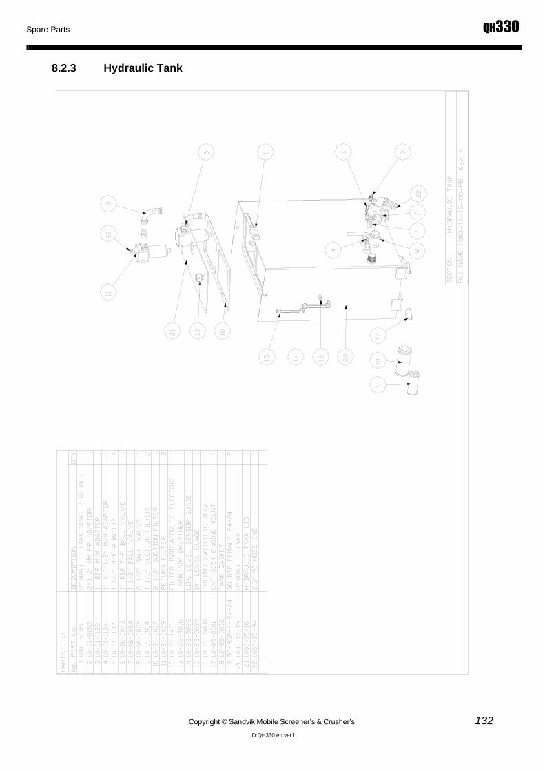
Spare Parts QH330
Copyright © Sandvik Mobile Screener’s & Crusher’s 132ID:QH330.en.ver1
8.2.3 Hydraulic Tank

QH330 Spare Parts
133 Copyright © Sandvik Mobile Screener’s & Crusher’s
ID:QH330.en.ver1
8.2.4 Diesel Tank

Spare Parts QH330
Copyright © Sandvik Mobile Screener’s & Crusher’s 134ID:QH330.en.ver1
8.2.5 Feed Conveyor

QH330 Spare Parts
135 Copyright © Sandvik Mobile Screener’s & Crusher’s
ID:QH330.en.ver1

Spare Parts QH330
Copyright © Sandvik Mobile Screener’s & Crusher’s 136ID:QH330.en.ver1

QH330 Spare Parts
137 Copyright © Sandvik Mobile Screener’s & Crusher’s
ID:QH330.en.ver1
8.2.6 Feeder Support Framet

Spare Parts QH330
Copyright © Sandvik Mobile Screener’s & Crusher’s 138ID:QH330.en.ver1
8.2.7 Main Conveyor

QH330 Spare Parts
139 Copyright © Sandvik Mobile Screener’s & Crusher’s
ID:QH330.en.ver1

Spare Parts QH330
Copyright © Sandvik Mobile Screener’s & Crusher’s 140ID:QH330.en.ver1
8.2.8 Main Conveyor lower section

QH330 Spare Parts
141 Copyright © Sandvik Mobile Screener’s & Crusher’s
ID:QH330.en.ver1

Spare Parts QH330
Copyright © Sandvik Mobile Screener’s & Crusher’s 142ID:QH330.en.ver1
8.2.9 Cone Crusher Assembly

QH330 Spare Parts
143 Copyright © Sandvik Mobile Screener’s & Crusher’s
ID:QH330.en.ver1

Spare Parts QH330
Copyright © Sandvik Mobile Screener’s & Crusher’s 144ID:QH330.en.ver1
8.2.10 Cone discharge Chute

QH330 Spare Parts
145 Copyright © Sandvik Mobile Screener’s & Crusher’s
ID:QH330.en.ver1

Spare Parts QH330
Copyright © Sandvik Mobile Screener’s & Crusher’s 146ID:QH330.en.ver1
8.2.11 Cone Access Frame

QH330 Spare Parts
147 Copyright © Sandvik Mobile Screener’s & Crusher’s
ID:QH330.en.ver1
8.2.12 Control Box

Spare Parts QH330
Copyright © Sandvik Mobile Screener’s & Crusher’s 148ID:QH330.en.ver1
8.2.13 Cone Lubrication Pump Kit

QH330 Spare Parts
149 Copyright © Sandvik Mobile Screener’s & Crusher’s
ID:QH330.en.ver1
8.2.14 Hydroset Pump Kit

Spare Parts QH330
Copyright © Sandvik Mobile Screener’s & Crusher’s 150ID:QH330.en.ver1
8.2.15 Lubrication Tank

QH330 Spare Parts
151 Copyright © Sandvik Mobile Screener’s & Crusher’s
ID:QH330.en.ver1
8.2.16 Hydroset tank

Spare Parts QH330
Copyright © Sandvik Mobile Screener’s & Crusher’s 152ID:QH330.en.ver1
8.2.17 Powerunit

QH330 Spare Parts
153 Copyright © Sandvik Mobile Screener’s & Crusher’s
ID:QH330.en.ver1

Spare Parts QH330
Copyright © Sandvik Mobile Screener’s & Crusher’s 154ID:QH330.en.ver1
8.2.18 Recommended Spare Parts - 2000 Hours

QH330 Spare Parts
155 Copyright © Sandvik Mobile Screener’s & Crusher’s
ID:QH330.en.ver1

Spare Parts QH330
Copyright © Sandvik Mobile Screener’s & Crusher’s 156ID:QH330.en.ver1
8.2.19 Rubber Kit
8.2.20 CAT Engine Spare PartsPart No qty per Description
Engine
15-30-0196 1 Primary air filter 6I-2509 (C11 & 13)15-22-0193 1 Secondary air filter 6I-2510 (C11 & 13)15-30-0194 1 Engine Oil Filter 1R-1808 (C11 & 13)15-30-0192 1 Water Trap 1R-0771 (C9 III & C11 & C13)15-30-0191 1 Secondary fuel filter 1R-0762 (C11 & 13)
15-30-0340 1 Priming Pump (Hand) 105-2508 (C9,11 & 13)15-30-0341 1 Regulator (Temperature) 247-7133 (C9,11 & 13)15-30-0342 1 Coolant Level Sensor 165-6634 (C9,11 & 13)15-30-0343 1 Start Motor 207-1556 (C9,11 & 13)15-30-0344 1 Alternator 80amp 177-9953 (C9,11 & 13)15-30-0346 1 Vee Belt Set 7M-4705 (C11 & 13)

QH330
Copyright © Sandvik Mobile Screener’s & Crusher’s 157ID:QH330.en.ver1
9.0 Electrical and Hydraulic

ELECTRICAL & HYDRAULICS QH330
Copyright © Sandvik Mobile Screener’s & Crusher’s 158ID:QH330.en.ver1
9.1 Electrical Schematics

QH330 ELECTRICAL & HYDRAULICS
159 Copyright © Sandvik Mobile Screener’s & Crusher’s
ID:QH330.en.ver1

ELECTRICAL & HYDRAULICS QH330
Copyright © Sandvik Mobile Screener’s & Crusher’s 160ID:QH330.en.ver1

QH330 ELECTRICAL & HYDRAULICS
161 Copyright © Sandvik Mobile Screener’s & Crusher’s
ID:QH330.en.ver1

ELECTRICAL & HYDRAULICS QH330
Copyright © Sandvik Mobile Screener’s & Crusher’s 162ID:QH330.en.ver1

QH330 ELECTRICAL & HYDRAULICS
163 Copyright © Sandvik Mobile Screener’s & Crusher’s
ID:QH330.en.ver1

ELECTRICAL & HYDRAULICS QH330
Copyright © Sandvik Mobile Screener’s & Crusher’s 164ID:QH330.en.ver1

QH330 ELECTRICAL & HYDRAULICS
165 Copyright © Sandvik Mobile Screener’s & Crusher’s
ID:QH330.en.ver1

ELECTRICAL & HYDRAULICS QH330
Copyright © Sandvik Mobile Screener’s & Crusher’s 166ID:QH330.en.ver1

QH330 ELECTRICAL & HYDRAULICS
167 Copyright © Sandvik Mobile Screener’s & Crusher’s
ID:QH330.en.ver1

ELECTRICAL & HYDRAULICS QH330
Copyright © Sandvik Mobile Screener’s & Crusher’s 168ID:QH330.en.ver1

QH330 ELECTRICAL & HYDRAULICS
169 Copyright © Sandvik Mobile Screener’s & Crusher’s
ID:QH330.en.ver1

ELECTRICAL & HYDRAULICS QH330
Copyright © Sandvik Mobile Screener’s & Crusher’s 170ID:QH330.en.ver1

QH330 ELECTRICAL & HYDRAULICS
171 Copyright © Sandvik Mobile Screener’s & Crusher’s
ID:QH330.en.ver1
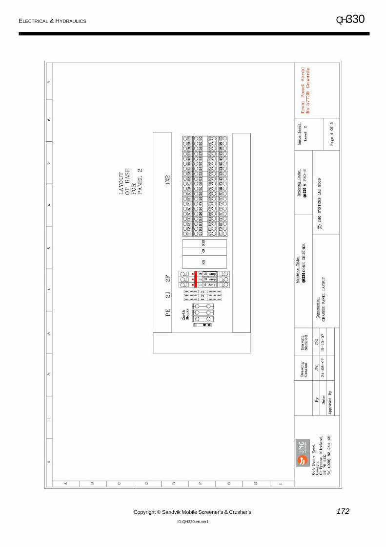
ELECTRICAL & HYDRAULICS QH330
Copyright © Sandvik Mobile Screener’s & Crusher’s 172ID:QH330.en.ver1

QH330 ELECTRICAL & HYDRAULICS
173 Copyright © Sandvik Mobile Screener’s & Crusher’s
ID:QH330.en.ver1

ELECTRICAL & HYDRAULICS QH330
Copyright © Sandvik Mobile Screener’s & Crusher’s 174ID:QH330.en.ver1
9.2 Hydraulic
9.2.1 Hydarulic circuit

QH330 ELECTRICAL & HYDRAULICS
175 Copyright © Sandvik Mobile Screener’s & Crusher’s
ID:QH330.en.ver1
Pipe
78
(see
Coo
ler
Cir
cuit)
Manifold(X)
Oil
Coo
ler
See
Hyd
rase
tC
ircu
it
AB
Feed
er M
otor
130c
c
Eng
ine
Tra
ck L
.H.S
T
rack
R.H
.S
Mai
n C
onve
yor
Main Lift Ram
Feed Conveyor Fold
Main Lift Ram
To
X
See
Cru
sher
Dri
veC
lose
d L
oop
Cir
cuit
Mai
n C
ontr
ol C
ircu
it
Y
To
X
To
X
To
XT
o X
To
X
To
X
To
Y
To
X

ELECTRICAL & HYDRAULICS QH330
Copyright © Sandvik Mobile Screener’s & Crusher’s 176ID:QH330.en.ver1
Hyd
raul
icO
il C
oole
r.
Lub
rica
tion
Oil
Coo
ler.

QH330 ELECTRICAL & HYDRAULICS
177 Copyright © Sandvik Mobile Screener’s & Crusher’s
ID:QH330.en.ver1
Eng
ine
250c
c
See
Mai
nC
ontr
ol C
ircu
it
250c
c
Clo
sed
Loo
p C
ircu
it

ELECTRICAL & HYDRAULICS QH330
Copyright © Sandvik Mobile Screener’s & Crusher’s 178ID:QH330.en.ver1
A
See
Mai
nC
ircu
it RCB
T
HY
DR
ASE
T T
AN
K
Hyd
rose
t Cir
cuit

QH330 ELECTRICAL & HYDRAULICS
179 Copyright © Sandvik Mobile Screener’s & Crusher’s
ID:QH330.en.ver1
Lub
rica
tion
Cir
cuit
Oil
Coo
ler
See
Coo
ler
Cir
cuit
LU
B T
AN
K

ELECTRICAL & HYDRAULICS QH330
Copyright © Sandvik Mobile Screener’s & Crusher’s 180ID:QH330.en.ver1
9.2.2 Hydraulic Components

QH330 ELECTRICAL & HYDRAULICS
181 Copyright © Sandvik Mobile Screener’s & Crusher’s
ID:QH330.en.ver1
9.2.3 Hydraulics Fittings

ELECTRICAL & HYDRAULICS QH330
Copyright © Sandvik Mobile Screener’s & Crusher’s 182ID:QH330.en.ver1

QH330 ELECTRICAL & HYDRAULICS
183 Copyright © Sandvik Mobile Screener’s & Crusher’s
ID:QH330.en.ver1
9.2.4 Hydraulic hose kits
Descriptio QH330 Chassis Hose kit 1T(bar) 2T(bar)1/4” 225 4003/8” 180 3301/2” 160 275
Part no. 10-29-1081 3/4” 105 215Rev-36 1” 90 175
1 1/4” 65 1401 1/2” 50 100
Page 1 of 14 2” 40 90Ref No. Description Part No. Length Coupling Orient. Type Qty Spiral Wrap
C003 LS Control Sensor to C/Valve 10-29-8003 10200 90-90 12-12 R2-06 1C011 Main Conveyor Return from BHD to Manifold 10-29-8011 5300 90-90 12-3 R1-12 1C012 Main Conveyor Pressure from BHD to C/V 10-29-8012 7700 90-90 12-6 R2-12 1C013 Track Bleed From BHD to Manifold 10-29-8013 5100 90-90 12-12 R1-06 2C028 Return from Main C/V to Manifold 10-29-8028 4000 90-ST R1-20 1
C029 P from Filter to Main C/V 10-29-8029 560
90°BSP-90°BSP
(6000psi) 12-6 R13-20 1
C030 P from BHD to Main C/V Filter 10-29-8030 690090°BSP-ST
BSP (6000psi) R13-20 1C056 Chassis BH to Heat Exchanger bottom 10-29-8056 700 90-ST R1-16 1C059 P/From Aux Pump to Control box 10-29-8059 7500 90-ST 12-9 R2-08 1C060 Heat Exchanger top to Chassis BH 10-29-8060 1200 90-ST R1-16 1C067 C/Valve to BH Raise/Lower Cone 10-29-8067 2300 90-90 12-6 R1-06 2C070 P/Unit Cooler to BH C/Box 10-29-8070 8500 90-ST R2-08 1C123 Cone Air Blower Hose 10-29-8123 5500 90-ST R1-12 1C124 C/Box BH to Chassis BH 10-29-8124 7400 ST-ST R1-16 1C125 Chassis B/H to Oil Cooler 10-29-8125 6900 90-ST R1-16 1C140 From BH to oil cooler motor drive 10-29-8140 8500 90-ST R2-08 1C142 From BH to return oil manifold 10-29-8142 1100 90-ST R2-08 1C021 Feeder Drive C/V to BHD 10-29-8021 6100 90-ST R2-12 1 700C022 Feeder Return BHD to Manifold 10-29-8022 2900 90-ST R1-12 1 700C024 Feeder Bleed BHD to Manifold 10-29-8024 2800 90-ST R1-06 1 700
Descriptio QH330 Powerunit Hose kit 1T(bar) 2T(bar)1/4” 225 4003/8” 180 3301/2” 160 275
Part no. 10-29-1082 3/4” 105 215Rev-36 1” 90 175
1 1/4” 65 1401 1/2” 50 100
Page 2 of 14 2” 40 90Ref No. Description Part No. Length Coupling Orient. Type Qty Spiral Wrap
C002 Diesel Suction From Tank to Water Trap 10-29-8002 2200 ST-Banjo R1-08 1C025 Diesel Suction from Pump to Water Trap 10-29-8025 1600 90-ST R1-08 1C038 Return from Pump Filter to Pump 10-29-8038 800 90-90 12-3 R1AT-12 1C039 Pressure from Pump to Filter 10-29-8039 800 90-90 12-11 R1AT-12 1C040 Heat Ex to Top Fitting 10-29-8040 320 90-ST R1AT-16 1C041 Heat Ex to Bottom Fitting 10-29-8041 550 90-90 12-12 R1AT-16 1C042 Manifold to Hyd Tank Return 10-29-8042 1200 90-ST R1AT-24 2C047 Diesel Tank to W/T 10-29-8047 1200 Banjo-ST R1AT-08 1C053 Suction From Tank To Large Pump 10-29-8053 1600 90-45 12-6 R1-24 1
C061 Pump to BH P/Unit 1 Flange 10-29-8061 210090° I'Lock
Flange+ ST BSP 6000psi R13-20 1
C093 Radiator to Engine 10-29-8093 650 90-ST R1-06 1C095 Suction From Tank To Small Pump 10-29-8095 600 ST-ST R1-16 1C098 Suction pipe from Hyd Tank to Pump 10-29-8098 1550 Do not swag SAE 100 R4 2 ½” 1
C121 Pump to C/M Top 10-29-8121 1610
1 1/4” ST I'Lock Flange+ 1 ½” 45°
I'Lock Flange 6000psi
Rock15-20 1 Spring guard (full length)
C122 Pump to C/M Bottom 10-29-8122 1520
1 ¼” ST I'Lock Flange+ 1 ½” 45°
I'Lock Flange 6000psi Rock15-20 1 Spring guard (full length)
C108 Air Filter to BHD 10-29-8108 700 90-ST R703- 3/16 1
Descriptio QH330 Main Conveyor Hose kit 1T(bar) 2T(bar)1/4” 225 4003/8” 180 3301/2” 160 275
Part no. 10-29-1083 3/4” 105 215Rev-36 1” 90 175
1 1/4” 65 1401 1/2” 50 100
Page 3 of 14 2” 40 90Ref No. Description Part No. Length Coupling Orient. Type Qty Spiral Wrap
C004 Main Conveyor P BHD to Lower BHD 10-29-8004 4800 90-ST R2-12 1C005 Main Conveyor R BHD to Lower BHD 10-29-8005 4800 90-ST R1-12 1C006 Main Conveyor P from BHD to Motor 10-29-8006 1300 90-90 12-1 R2-12 1C007 Main Conveyor R from BHD to Motor 10-29-8007 1350 90-90 12-1 R1-12 1
Working Pressures
Tullyvannon,Ballygawley,Co. Tyrone N. Ireland
Tel: 028 85567799Fax: 028 85567007
Working Pressures
Tullyvannon,Ballygawley,Co. Tyrone N. Ireland
Tel: 028 85567799Fax: 028 85567007
Working Pressures
Tullyvannon,Ballygawley,Co. Tyrone N. Ireland
Tel: 028 85567799Fax: 028 85567007

ELECTRICAL & HYDRAULICS QH330
Copyright © Sandvik Mobile Screener’s & Crusher’s 184ID:QH330.en.ver1
Descriptio QH330 Track Hose kit 1T(bar) 2T(bar)1/4” 225 4003/8” 180 3301/2” 160 275
Part no. 10-29-1084 3/4” 105 215Rev-36 1” 90 175
1 1/4” 65 1401 1/2” 50 100
Page 4 of 14 2” 40 90Ref No. Description Part No. Length Coupling Orient. Type Qty Spiral Wrap
C008 Track Drive from BHD to C/V 10-29-8008 7300 90-90 12-11 R2-12 4C009 Track Drive from BHD to Motor 10-29-8009 800 45-ST R2-12 4C010 Track Bleed from BHD to Motor 10-29-8010 1300 90-ST R1-06 2
Descriptio QH330 Auxilary Hose kit 1T(bar) 2T(bar)1/4” 225 4003/8” 180 3301/2” 160 275
Part no. 10-29-1085 3/4” 105 215Rev-36 1” 90 175
1 1/4” 65 1401 1/2” 50 100
Page 5 of 14 2” 40 90Ref No. Description Part No. Length Coupling Orient. Type Qty Spiral Wrap
C014 Main Conveyor Tee to Lower 10-29-8014 1850 90-ST R2-06 2 1450C015 Main Conveyor Tee to Raise 10-29-8015 1400 90-ST R2-06 2 1000C018 Aux C/V P from C/V 10-29-8018 3700 90-90 12-3 R2-08 1C019 Aux C/V T from Manifold 10-29-8019 1000 90-90 12-12 R1-08 1C020 Aux C/V to Tee on M/C Raise/Lower 10-29-8020 2200 90-90 12-3 R2-06 2C026 Raise Feeder C/V to Ram 10-29-8026 1150 90-ST R2-06 1C027 Lower Feeder C/V to Ram 10-29-8027 1700 90-ST R2-06 1
Descriptio QH330 Feeder Hose kit 1T(bar) 2T(bar)1/4” 225 4003/8” 180 3301/2” 160 275
Part no. 10-29-1086 3/4” 105 215Rev-36 1” 90 175
1 1/4” 65 1401 1/2” 50 100
Page 6 of 14 2” 40 90Ref No. Description Part No. Length Coupling Orient. Type Qty Spiral Wrap
C016 Feeder P from Motor to BHD 10-29-8016 800 ST-ST R2-12 1C017 Feeder R from Motor to BHD 10-29-8017 840 ST-ST R1-12 1C023 Feeder Bleed to BHD 10-29-8023 1200 90-ST R1-06 1
Descriptio QH330 Cone Hose kit 1T(bar) 2T(bar)1/4” 225 4003/8” 180 3301/2” 160 275
Part no. 10-29-1087 3/4” 105 215Rev-36 1” 90 175
1 1/4” 65 1401 1/2” 50 100
Page 7 of 14 2” 40 90Ref No. Description Part No. Length Coupling Orient. Type Qty Spiral Wrap
C001 Cone to BHD 10-29-8001 540 90-ST R1-16 1
C036 BHD to Cone Accumulator 10-29-8036 127090°BSP-ST
BSP (6000psi) HR9R-32 1C099 Lubrication Drain pipe Long (10 Bar) 10-29-8099 1150 3" Suction 1C100 Lubrication Drain Pipe Short (10 bar) 10-29-8100 300 3" Suction 1C043 Bleed from C/M to Pump 10-29-8043 1720 45-ST R1AT-06 1C044 Case Drain from C/M to Pump 10-29-8044 2400 90-90 12-9 R1AT-16 1
Working Pressures
Tullyvannon,Ballygawley,Co. Tyrone N. Ireland
Tel: 028 85567799Fax: 028 85567007
Working Pressures
Tullyvannon,Ballygawley,Co. Tyrone N. Ireland
Tel: 028 85567799Fax: 028 85567007
Working Pressures
Tullyvannon,Ballygawley,Co. Tyrone N. Ireland
Tel: 028 85567799Fax: 028 85567007
Working Pressures
Tullyvannon,Ballygawley,Co. Tyrone N. Ireland
Tel: 028 85567799Fax: 028 85567007

QH330 ELECTRICAL & HYDRAULICS
185 Copyright © Sandvik Mobile Screener’s & Crusher’s
ID:QH330.en.ver1
Descriptio QH330 Lubrication Oil Cooler Hose kit 1T(bar) 2T(bar)1/4” 225 4003/8” 180 3301/2” 160 275
Part no. 10-29-1088 3/4” 105 215Rev-36 1” 90 175
1 1/4” 65 1401 1/2” 50 100
Page 8 of 14 2” 40 90Ref No. Description Part No. Length Coupling Orient. Type Qty Spiral Wrap
C055 Lub BH Cone to Oil Cooler 10-29-8055 2500 90-ST R1-16 1C062 Lub Oil Cooler to M/F 10-29-8062 2000 90-ST R1-08 1C066 E/Bay BH to Oil Cooler 10-29-8066 3400 90-ST R2-08 1C082 Oil Cooler Loop 10-29-8082 500 ST-ST R2-08 1C096 Lub Oil Cooler Bleed 10-29-8096 350 90-90 12-1 R1-08 1
Descriptio QH330 Hydraulic Oil Cooler Hose kit 1T(bar) 2T(bar)1/4” 225 4003/8” 180 3301/2” 160 275
Part no. 10-29-1089 3/4” 105 215Rev-36 1” 90 175
1 1/4” 65 1401 1/2” 50 100
Page 9 of 14 2” 40 90Ref No. Description Part No. Length Coupling Orient. Type Qty Spiral Wrap
C032 Manifold to Oil Cooler Top 10-29-8032 8400 90-ST R1-20 1C033 Oil Cooler Motor to Manifold P/Unit 10-29-8033 3400 90-ST R1-08 1C082 Oil Cooler Loop 10-29-8082 500 ST-ST R2-08 1C097 Top Oil Cooler to M/F 10-29-8097 3100 90-ST R1-20 1C057 Main Pump Case Drain to Tank 10-29-8057 4300 90-Banjo R1-16 1C058 Small Pump Case Drain to Tank 10-29-8058 4600 90-Banjo R1-16 1
Descriptio QH330 Control Box Hose kit 1T(bar) 2T(bar)1/4” 225 4003/8” 180 3301/2” 160 275
Part no. 10-29-1090 3/4” 105 215Rev-36 1” 90 175
1 1/4” 65 1401 1/2” 50 100
Page 10 of 14 2” 40 90Ref No. Description Part No. Length Coupling Orient. Type Qty Spiral Wrap
C064 Lub Tank to Motor 10-29-8064 1380 90-ST R1-24 1C065 Lub Motor to Filter 10-29-8065 270 90-90 12-3 R1-16 1C068 B/H to Pump Top Raise/Lower Cone 10-29-8068 1600 90-90 12-6 R2-06 1C069 B/H to Pump Top Raise/Lower Cone 10-29-8069 1600 90-90 12-3 R2-06 1C071 BH Control Box to Accum 10-29-8071 2100 90-ST R2-08 1C072 Hydro Set Tank Bh to Block 10-29-8072 850 90-ST R1-12 1C073 BTM Pump to Hydroset Block 10-29-8073 900 90-90 12-7 R1-12 1C074 BTM Pump to Hydroset Block 10-29-8074 900 90-ST R1-12 1C075 Hydroset Block to Filter 10-29-8075 450 90-90 12+3 R1-08 1C076 Hydroset Block to BH Accum 10-29-8076 450 ST-ST R1-08 1C077 BH to Tank Hydroset 10-29-8077 210 90-90 12-12 R1-08 1C078 Top Lub Pump Bleed to BH 10-29-8078 900 ST-ST R1-06 1C079 Hydroset Pump to Bleed to BH 10-29-8079 230 90-ST R1-06 1C080 Hydroset Motor Bleed to Filter Tee 10-29-8080 650 90-ST R1-06 1C081 Motor Bleed BH to M/F 10-29-8081 1150 90-ST R1-06 1C083 Hydroset Tank to B/H 10-29-8083 380 90-90 12-6 R1-12 1C084 Lub Filter to BH 10-29-8084 550 90-ST R1-16 1C085 Oil Cooler Sol to BH 10-29-8085 320 90-ST R1-08 1C086 Oil Cooler Sol BH to M/F 10-29-8086 1000 90-ST R1-08 1C087 Oil Cooler Sol to Motor BH 10-29-8087 230 90-ST R2-08 1C088 Lub Sol to Oil Cooler Sol 10-29-8088 400 90-ST R2-08 1C089 PRV to BH return to manifold 10-29-8089 700 90-ST R2-08 1C090 Lub Sol to Pump 10-29-8090 500 90-90 12-12 R2-08 1C091 Lub Pump to Lub sol 10-29-8091 500 90-ST R2-08 1C094 Hydroset Filter to BH 10-29-8094 350 ST-ST R1-08 1C138 Lube valve port 2 to pressure reliefe valve 10-29-8138 560 90-ST R2-08 1C139 From oil cooler return BH to oil cooler valve port 10-29-8139 560 90-ST R2-08 1C141 From Pressure relief valve to BH 10-29-8141 500 90-ST R2-08 1
Working Pressures
Tullyvannon,Ballygawley,Co. Tyrone N. Ireland
Tel: 028 85567799Fax: 028 85567007
Working Pressures
Tullyvannon,Ballygawley,Co. Tyrone N. Ireland
Tel: 028 85567799Fax: 028 85567007
Working Pressures
Tullyvannon,Ballygawley,Co. Tyrone N. Ireland
Tel: 028 85567799Fax: 028 85567007

ELECTRICAL & HYDRAULICS QH330
Copyright © Sandvik Mobile Screener’s & Crusher’s 186ID:QH330.en.ver1
Descriptio QH330 Grease Pipes 1T(bar) 2T(bar)1/4” 225 4003/8” 180 3301/2” 160 275
Part no. 10-29-1091 3/4” 105 215Rev-36 1” 90 175
1 1/4” 65 1401 1/2” 50 100
Page 11 of 14 2” 40 90Ref No. Description Part No. Length Coupling Orient. Type Qty Spiral Wrap
C101 Main Conveyor RH Tail Bearing to BHD 10-29-8101 3200 90-90 12-6 R703- 3/16 1C102 Main Conveyor LH Tail Bearing to BHD 10-29-8102 4100 90-90 12-12 R703- 3/16 1C103 Main Conveyor RH Head Bearing to BHD 10-29-8103 5360 90-90 12-6 R703- 3/16 1C104 Main Conveyor LH Head Bearing to BHD 10-29-8104 6200 90-90 12-12 R703- 3/16 1C105 Feeder LH Head Bearing to BHD 10-29-8105 6100 90-90 12-12 R703- 3/16 1C106 Feeder Conveyor RH Tail Bearing to BHD 10-29-8106 2050 90-ST R703- 3/16 1C107 Feeder Conveyor LH Tail Bearing to BHD 10-29-8107 950 90-ST R703- 3/16 1
Descriptio QH330 Refuelling kit 1T(bar) 2T(bar)1/4” 225 4003/8” 180 3301/2” 160 275
Part no. 10-29-1092 3/4” 105 215Rev-36 1” 90 175
1 1/4” 65 1401 1/2” 50 100
Page 12 of 14 2” 40 90Ref No. Description Part No. Length Coupling Orient. Type Qty Spiral WrapC126 Diesel pump to Diesel reservoir 10-29-8126 4000 90+ST R1AT-12 1C127 Diesel pump to Diesel tank 10-29-8127 2200 90+90 12-6 R1AT-12 1
Descriptio QH330 -30 degree kit 1T(bar) 2T(bar)1/4” 225 4003/8” 180 3301/2” 160 275
Part no. 10-29-1093 3/4” 105 2151” 90 175
1 1/4” 65 1401 1/2” 50 100
Page 13 of 14 2” 40 90Ref No. Description Part No. Length Coupling Orient. Type Qty Spiral WrapC128 Heater out - engine top 10-29-8128 2500 90-90 R1AT-20 1C129 engine bottom - lub tank 10-29-8129 8700 ST-ST R1AT-20 1C130 lub tank - hydraset tank 10-29-8130 3550 90-ST R1AT-20 1C131 hydraset tank - hydraulic tank 10-29-8131 13200 90-90 12-6 R1AT-20 1C132 hydraset tank - heater in 10-29-8132 3050 90-ST R1AT-20 1
Descriptio QH330 Additional Oil Cooler Kit 1T(bar) 2T(bar)1/4” 225 4003/8” 180 3301/2” 160 275
Part no. 10-29-1094 3/4” 105 2151” 90 175
1 1/4” 65 1401 1/2” 50 100
Page 14 of 14 2” 40 90Ref No. Description Part No. Length Coupling Orient. Type Qty Spiral WrapC133 10-29-8133 3700 90+90 12-12 R2AT-08 1C134 10-29-8134 4000 90-ST R1AT-20 1C135 10-29-8135 3100 90-ST R1AT-20 1C136 Oil Cooler Motor Return Extension 10-29-8136 1000 90-ST R1AT-08 1C082 Oil Cooler Loop 10-29-8082 500 ST-ST R2AT-08 1C137 Case Drain 10-29-8137 3710 90-ST R1AT-08 1
Working Pressures
Tullyvannon,Ballygawley,Co. Tyrone N. Ireland
Tel: 028 85567799Fax: 028 85567007
Working Pressures
Tullyvannon,Ballygawley,Co. Tyrone N. Ireland
Tel: 028 85567799Fax: 028 85567007
Working Pressures
Tullyvannon,Ballygawley,Co. Tyrone N. Ireland
Tel: 028 85567799Fax: 028 85567007
Working Pressures
Tullyvannon,Ballygawley,Co. Tyrone N. Ireland
Tel: 028 85567799Fax: 028 85567007

QH330
Copyright © Sandvik Mobile Screener’s & Crusher’s 187ID:QH330.en.ver1
10.0 OEM Section

OEM Manuals QH330
Copyright © Sandvik Mobile Screener’s & Crusher’s 188ID:QH330.en.ver1
10.1 OEM Appendicies
Please ensure you read this section carefully. It contains Manuals produced by OEM manufactures, thereforeSandvik has resevations for misprints. The OEM Manuals will be placed in the following order
10.1.1 CH430 CONE Crusher Operation
10.1.2 CH430 CONE Crusher Maintenace Manual
10.1.3 CH430 CONE Crusher Spare Partsl
10.1.4 CH430 CONE Crusher Wear Parts
10.1.5 Crawler Tracks Operation Manual
10.1.6 M-PROS Control System Spare Parts
10.1.7 Optional Extra’s