
SAMSON Catalog - s Industriales
116
Products Catalog
Transcript of SAMSON Catalog - s Industriales
Products
Catalog
2011
-06
WS
· K 2
0 EN
SAM
SON
Prod
ucts
SAMSON AG · MESS- UND REGELTECHNIK Weismüllerstraße 3 · 60314 Frankfurt am Main · GermanyPhone: +49 69 4009-0 · Fax: +49 69 4009-1507 E-mail: [email protected] · Internet: www.samson.de · www.samsongroup.de

OverviewCatalog 2011
Products
Appendix
Pipeline Fittings
Pilot-operated Universal Regulators
Self-operated Flow and Differential Pressure Regulators
Self-operated Pressure Regulators
Self-operated Temperature Regulators
Electronic Controllers and Sensors
Pressure Regulators for Cryogenics
Media Series
Electronic Process Controllers
Converters
Valve Accessories
Software
Positioners
Actuators
Control Valves
93
90
89
81
74
65
55
53
51
48
46
43
42
39
35
7
1

Control Valves
Globe valve · Type 3241 7
Three-way valve · Type 3244 9
Micro-flow valve · Type 3510 High-pressure valve · Type 3252 10
Globe valve · Type 3251 Angle valve · Type 3256 11
Three-way valve · Type 3253 Globe valve · Type 3254 12
Steam-converting valves Type 3281, Type 3286 and Type 3284 13
Low-noise and low-wear components Flow dividers · AC-trim · Perforated plug Type 3381 Silencer 14
Diaphragm valve · Type 3345 On-off valve · Type 3351 15
Pneumatic Control Valves for Hygienic and Aseptic Services Angle valves · Type 3347 and Type 3249 16
Cryogenic valves · Type 3248 17 Type 3246 with long extension bonnet and circulation inhibitor 18
Butterfly valves · Type 3331, Type 3335 and Type 3237 19 Butterfly valves · Pfeiffer Type BR 10a, BR 10e and BR 14b/31a High-pressure butterfly valve · LEUSCH Type LTR 43 20
PTFE- or PFA-lined Control Valves Globe valves · Pfeiffer Type BR 1a, BR 1b and BR 6a Angle valve · Pfeiffer Type BR 8a 21
Ball Valves and Pigging Valves Lined ball valves · Pfeiffer Type BR 20a and BR 20b Stainless steel ball valves · Pfeiffer Type BR 22a and BR 26 22 Pigging valves · Pfeiffer Type BR 28 and BR 29 Sampling valve · Pfeiffer Type BR 27 23
Rotary plug valves · VETEC Type 72.x/AT and Type 72.x/R 24
Rotary plug valves · VETEC Type 82.7/R and Type 82.7/AT 25
High-pressure Valve Series Rotary plug valves · VETEC Type 73.x/R and Type 73.x/M 26
VETEC Type 72.x/AT DVGW and Type 72.x/MN DVGW Control and quick-acting shut-off valves for gases 27
Segmented ball valve · Type 3310/BR 31a 28
Control Valves for HVAC and Industrial Applications V2001 Valve Series Globe valve · Type 3321 Three-way valve · Type 3323 29
Valve Series V2001 Globe valve for heat transfer oil · Type 3531 Three-way valve for heat transfer oil · Type 3535 30
Globe valves · Type 3213 and Type 3214 Globe valve/three-way valve · Type 3260 31
Globe valve · Type 3222 Three-way valve · Type 3226 32
Control Valves/Controllers with Electric Actuators Type 3213 Globe Valve with Types 5757, 5724, 5757-7, 5725 Controllers with Electric Actuators Type 3214 Globe Valve with Types 5724, 5725 Controllers with Electric Actuators Type 3260 Three-way Valve with Types 5757, 5724, 5725, 5757-7 Controllers with Electric Actuators 33 Type 3222 Globe Valve with Types 5757, 5724, 5725, 5757-7 Controllers with Electric Actuators Type 3222 N Globe Valve with Types 5757, 5757-7 Controllers with Electric Actuators Type 3226 Three-way Valve with Types 5757, 5724, 5725, 5757-7 Controllers with Electric Actuators 34
Actuators
Pneumatic actuators · Type 3277 and Type 3271 35
Pneumatic rotary actuators Type 3278 and Pfeiffer Type BR 31a (AT) 36
Electric actuators Types 5824, 5825, 5857 and Type 3374 Electrohydraulic actuator · Type 3274 37
Controllers with Electric Actuators Type 5724 · Type 5725 with fail-safe action · Type 5757 Type 5757-7 38
Positioners
Pneumatic and Electropneumatic Positioners Positioners · Type 3760, Types 4765/4763 and Types 3766/3767 EEx d positioner with Type 6116 i/p Converter 39
Contents
3
Electronic and Digital Positioners Electropneumatic positioners · Types 3730-0, 3730-1, 3730-2 HART® communication · Types 3730-3, 3731-3 40 PROFIBUS-PA · Type 3730-4 FOUNDATIONTM fieldbus · Types 3730-5, 3731-5 EXPERT valve diagnostics · Type 3770 Field Barrier 41
Software
TROVIS-VIEW 6661 SAMSON Valve Sizing 42
Valve Accessories
Limit switches · Type 4746, Type 3776, Type 4744 EEx d Electronic limit switch · Type 3738-20 Inductive limit switch · Type 3768 43 Position transmitter · Type 4748 Solenoid valves · Type 3701 and Type 3963 Pneumatic lock-up valve · Type 3709 44 Supply pressure regulator · Type 4708 Reversing amplifier · Type 3710 Pneumatic volume booster · Type 3755 45
Converters
i/p converters · Type 6111, Type 6116, Type 6126 and Type 6127 46 p/i converters · Type 6132 and Type 6134 47
Electronic Process Controllers
Compact controller · TROVIS 6493 Industrial controller · TROVIS 6495-2 48
Media Series
Differential pressure, flow rate and liquid level meters Media 5 · Media 05 51
Indicating digital transmitters for differential pressure Media 6 · Media 6 Z 52
Pressure Regulators for Cryogenics
Pressure Regulators for Cryogenics Pressure build-up regulator · Type 2357-3 53 Pressure reducing valves · Type 2357-1 and Type 2357-6 Excess pressure valves · Type 2357-2 and Type 2357-7 54
Electronic Controllers and Sensors
Heating and district heating controllers TROVIS 5610 · TROVIS 5573 · TROVIS 5575 TROVIS 5576 · TROVIS 5579 55 Programmable logic controller · TROVIS 5571 56 Meter bus gateway · TROVIS 5488 Web module · TROVIS 5590 57 Modbus I/O module for TROVIS 5571 Converter or repeater CoRe01 · DataMod 11 Meter bus/Modbus gateway · Modbus/TCP gateway 58
Solar controllers ZPR · ZPR-D · SOL3-1 · SOL3-7 · SOL71 59 Heat pump controllers WPR3 · WPR71 60
TROVIS MODULON Automation System CPU module · TROVIS 6503 A module · TROVIS 6506 B module · TROVIS 6507 AI module · TROVIS 6516 AO module · TROVIS 6517 Operating terminal · TROVIS 6515 62
TROVIS 6600 Automation System CPU module · TROVIS 6610 I/O module · TROVIS 6620 Input module · TROVIS 6625 Web terminal · TROVIS 6615 63
Temperature Sensors Resistors with Pt 100 · Pt 1000 64
Self-operated Temperature Regulators
Temperature regulators with Globe valve · Type 1/4 · Type 1u/4u Three-way valve · Type 8/9 65
Typetested safety equipment Safety temperature limiter (STL) · Type 2212 68
Typetested safety equipment Safety temperature monitor (STM) · Type 2213 69
Temperature regulators · Type 43-1 to Type 43-7 70
Temperature regulators with hydraulic controllers Type 43-8 · Type 43-8 N 71
Contents
4

Typetested safety equipment Safety temperature limiter with safety thermostat · Type 2439 K 72
Typetested safety equipment Safety temperature monitor with safety thermostat · Type 2403 K 73
Self-operated Pressure Regulators
Pressure reducing valve · Type 41-23 Excess pressure valve · Type 41-73 74
Pressure reducing valves · Type 2405 and Type 2407 Excess pressure valves · Type 2406 and Type 2408 76
Pressure regulators with pilot valve Pressure reducing valve · Type 2333 Excess pressure valve · Type 2335 77
Pressure reducing valves · Type 44-0 B and Type 44-1 B Excess pressure valve · Type 44-6 B 78
Pressure reducing valve · Type 44-2 Safety shut-off valve (SSV) · Type 44-3 Excess pressure valve · Type 44-7 Safety excess pressure valve (SEV) · Type 44-8 79
Self-operated pressure regulators for food processing and pharmaceutical industries Pressure reducing valve · Type 2371-11 Excess pressure valves · Type 2371-00 and Type 2371-01 80
Self-operated Flow and Differential Pressure Regulators
Check Valve (Backflow Prevention) · Type 42-10 RS 81
Differential pressure regulator with balanced valve Type 2422 82
Flow regulator · Type 42-36 83
Flow and differential pressure regulator · Type 42-37 Flow and differential pressure or pressure regulator Type 42-39 84
Differential pressure regulators with closing actuator Type 45-1 to Type 45-4 Flow regulator · Type 45-9 85
Flow and differential pressure regulators for return flow pipe · Type 46-7 and Type 47-5 for flow pipe · Type 47-1 and Type 47-4 86
Combined regulator with an additional electric actuator Flow regulators · Type 42-36 E 87
Combined regulators with an additional electric actuator Flow regulators · Type 2488/58... and Type 2489/58... 88
Pilot-operated Universal Regulators
Type 2334 89
Pipeline Fittings
Steam trap · Type 13 E 90
Air vent for water-operated systems, drain for air-operated systems · Type 6 Air vent for steam-operated systems · Type 3 91
Strainers, Y-shaped · Type 1N · Type 1NI · Type 1FN Type 2N · Type 2NI 92
Appendix
SAMSON Product Range 93
Valve sizing · Calculation of the KV coefficient 95
Data sheet for DIN control valves 97
Valve sizing · Calculation of the CV coefficient 99
Data sheet for ANSI control valves 101
SAMSON Subsidiaries, Agencies and Service Facilities Worldwide 103
Index 109
Contents
5

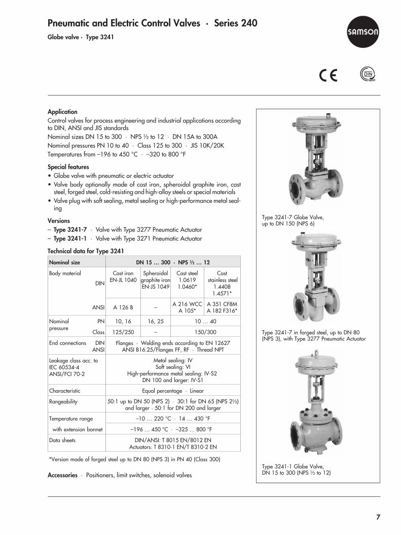
Pneumatic and Electric Control Valves · Series 240Globe valve · Type 3241
ApplicationControl valves for process engineering and industrial applications accordingto DIN, ANSI and JIS standardsNominal sizes DN 15 to 300 · NPS ½ to 12 · DN 15A to 300ANominal pressures PN 10 to 40 · Class 125 to 300 · JIS 10K/20KTemperatures from –196 to 450 °C · –320 to 800 °F
Special features• Globe valve with pneumatic or electric actuator• Valve body optionally made of cast iron, spheroidal graphite iron, cast
steel, forged steel, cold-resisting and high-alloy steels or special materials• Valve plug with soft sealing, metal sealing or high-performance metal seal-
ing
Versions– Type 3241-7 · Valve with Type 3277 Pneumatic Actuator– Type 3241-1 · Valve with Type 3271 Pneumatic Actuator
Technical data for Type 3241
Nominal size DN 15 … 300 · NPS ½ … 12
Body material
DIN
Cast ironEN-JL 1040
Spheroidalgraphite ironEN-JS 1049
Cast steel1.06191.0460*
Caststainless steel
1.44081.4571*
ANSI A 126 B – A 216 WCCA 105*
A 351 CF8MA 182 F316*
Nominalpressure
PN 10, 16 16, 25 10 … 40
Class 125/250 – 150/300
End connections DINANSI
Flanges · Welding ends according to EN 12627ANSI B16.25/Flanges FF, RF · Thread NPT
Leakage class acc. toIEC 60534-4ANSI/FCI 70-2
Metal sealing: IVSoft sealing: VI
High-performance metal sealing: IV-S2DN 100 and larger: IV-S1
Characteristic Equal percentage · Linear
Rangeability 50:1 up to DN 50 (NPS 2) · 30:1 for DN 65 (NPS 2½)and larger · 50:1 for DN 200 and larger
Temperature range –10 … 220 °C · 14 … 430 °F
ith extension bonnet –196 … 450 °C · –325 … 800 °F
Data sheets DIN/ANSI: T 8015 EN/8012 ENActuators: T 8310-1 EN/T 8310-2 EN
*Version made of forged steel up to DN 80 (NPS 3) in PN 40 (Class 300)
Accessories · Positioners, limit switches, solenoid valves
Type 3241-7 Globe Valve,up to DN 150 (NPS 6)
Type 3241-7 in forged steel, up to DN 80(NPS 3), with Type 3277 Pneumatic Actuator
Type 3241-1 Globe Valve,DN 15 to 300 (NPS ½ to 12)
w
7
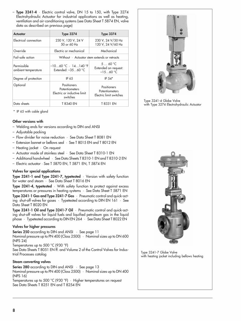
– Type 3241-4 · Electric control valve, DN 15 to 150, with Type 3274Electrohydraulic Actuator for industrial applications as well as heating,ventilation and air-conditioning systems (see Data Sheet T 5874 EN, valvedata as described on previous page)
Actuator Type 3274 Type 3374
Electrical connection 230 V, 120 V, 24 V50 or 60 Hz
230 V, 24 V/50 Hz120 V, 24 V/60 Hz
Override Electric or mechanical Mechanical
Fail-safe action Without · Actuator stem extends or retracts
Permissibleambient temperature
–10…60 °C · 14…140 °FExtended: –35…60 °C
5 … 60 °CExtended on request:
–15…60 °C
Degree of protection IP 65 IP 54*
Optional PositionersPotentiometers
Electric or inductive limitswitches
PositionersPotentiometers
Electric limit switches
Data sheets T 8340 EN T 8331 EN
* IP 65 with cable gland
Other versions with– Welding ends for versions according to DIN and ANSI– Adjustable packing– Flow divider for noise reduction · See Data Sheet T 8081 EN– Extension bonnet or bellows seal · See T 8015 EN and T 8012 EN– Heating jacket · On request– Actuator made of stainless steel · See Data Sheet T 8310-1 EN– Additional handwheel · See Data Sheets T 8310-1 EN and T 8310-2 EN– Electric actuator · See T 5870 EN, T 5871 EN, T 5874 EN
Valves for special applicationsType 3241-1 and Type 3241-7, typetested · Version with safety functionfor water and steam · See Data Sheet T 8016 ENType 3241-4, typetested · With safety function to protect against excesstemperatures or pressures in heating systems · See Data Sheet T 5871 ENType 3241-1 Gas and Type 3241-7 Gas · Pneumatic control and quick-act-ing shut-off valves for gases · Typetested according to DIN EN 161 · SeeData Sheet T 8020 ENType 3241-1 Oil and Type 3241-7 Oil · Pneumatic control and quick-act-ing shut-off valves for liquid fuels and liquified petroleum gas in the liquidphase · Typetested according to DIN EN 264 · See Data Sheet T 8022 EN
Valves for higher pressuresSeries 250 according to DIN and ANSI · See page 11Nominal pressure up to PN 400 (Class 2500) · Nominal sizes up to DN 600(NPS 24)Temperatures up to 500 °C (930 °F)See Data Sheets T 8051 EN ff. and Volume 2 of the Control Valves for Indus-trial Processes catalog
Steam converting valvesSeries 280 according to DIN and ANSI · See page 13Nominal pressure up to PN 400 (Class 2500) · Nominal sizes up to DN 400(NPS 16)Temperatures up to 500 °C (930 °F) · Higher temperatures on requestSee Data Sheets T 8251 EN and T 8254 EN
Type 3241-4 Globe Valvewith Type 3274 Electrohydraulic Actuator
Type 3241-7 Globe Valvewith heating jacket including bellows heating
8
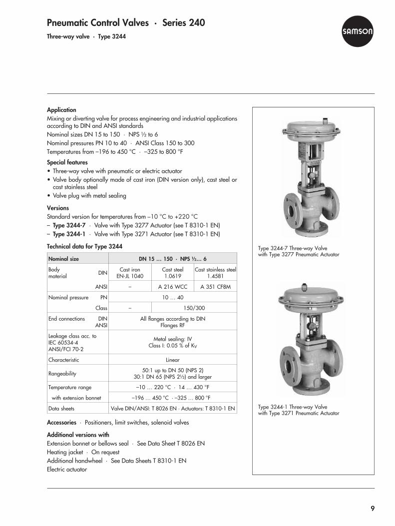
Pneumatic Control Valves · Series 240Three-way valve · Type 3244
ApplicationMixing or diverting valve for process engineering and industrial applicationsaccording to DIN and ANSI standardsNominal sizes DN 15 to 150 · NPS ½ to 6Nominal pressures PN 10 to 40 · ANSI Class 150 to 300Temperatures from –196 to 450 °C · –325 to 800 °F
Special features• Three-way valve with pneumatic or electric actuator• Valve body optionally made of cast iron (DIN version only), cast steel or
cast stainless steel• Valve plug with metal sealing
VersionsStandard version for temperatures from –10 °C to +220 °C– Type 3244-7 · Valve with Type 3277 Actuator (see T 8310-1 EN)– Type 3244-1 · Valve with Type 3271 Actuator (see T 8310-1 EN)
Technical data for Type 3244
Nominal size DN 15 … 150 · NPS ½… 6
Bodymaterial DIN Cast iron
EN-JL 1040Cast steel1.0619
Cast stainless steel1.4581
ANSI – A 216 WCC A 351 CF8M
Nominal pressure PN 10 … 40
Class – 150/300
End connections DINANSI
All flanges according to DINFlanges RF
Leakage class acc. toIEC 60534-4ANSI/FCI 70-2
Metal sealing: IVClass I: 0.05 % of KV
Characteristic Linear
Rangeability 50:1 up to DN 50 (NPS 2)30:1 DN 65 (NPS 2½) and larger
Temperature range –10 … 220 °C · 14 … 430 °F
ith extension bonnet –196 … 450 °C · –325 … 800 °F
Data sheets Valve DIN/ANSI: T 8026 EN · Actuators: T 8310-1 EN
Accessories · Positioners, limit switches, solenoid valves
Additional versions withExtension bonnet or bellows seal · See Data Sheet T 8026 ENHeating jacket · On requestAdditional handwheel · See Data Sheets T 8310-1 ENElectric actuator
Type 3244-7 Three-way Valvewith Type 3277 Pneumatic Actuator
Type 3244-1 Three-way Valvewith Type 3271 Pneumatic Actuator
w
9
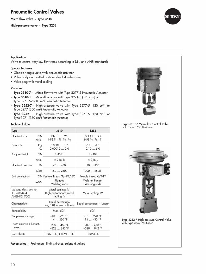
Pneumatic Control ValvesMicro-flow valve · Type 3510
High-pressure valve · Type 3252
ApplicationValve to control very low flow rates according to DIN and ANSI standards
Special features• Globe or angle valve with pneumatic actuator• Valve body and wetted parts made of stainless steel• Valve plug with metal sealing
Versions– Type 3510-7 · Micro-flow valve with Type 3277-5 Pneumatic Actuator– Type 3510-1 · Micro-flow valve with Type 3271-5 (120 cm²) or
Type 3271-52 (60 cm²) Pneumatic Actuator– Type 3252-7 · High-pressure valve with Type 3277-5 (120 cm²) or
Type 3277 (350 cm²) Pneumatic Actuator– Type 3252-1 · High-pressure valve with Type 3271-5 (120 cm²) or
Type 3271 (350 cm²) Pneumatic Actuator
Technical data
Type 3510 3252
Nominal size DINANSI
DN 10 … 25NPS ¼ · 3
8 · ½ · ¾DN 15 … 25NPS ½ · ¾ · 1
Flow rate KVSCv
0.0001 … 1.60.00012 … 2.0
0.1 … 4.00.12 … 5.0
Body material DIN 1.4571 1.4404
ANSI A 316 Ti A 316 L
Nominal pressure PN 40 … 400 40 … 400
Class 150 … 2500 300 … 2500
End connections DIN
ANSI
Female thread G/NPT/ISOFlanges
Welding ends
Female thread G/NPTWeld-on flangesWelding ends
Leakage class acc. toIEC 60534-4ANSI/FCI 70-2
Metal sealing: IVHigh-performance metal
sealing: VMetal sealing: IV
Characteristic Equal percentageKVS 0.01 onwards linear Equal percentage · Linear
Rangeability Max. 50:1 50:1
Temperature range
with extension bonnet,max.
–10 … 220 °C14 … 430 °F
–10 … 220 °C14 … 430 °F
–200 … 450 °C–328 … 842 °F
–200 … 450 °C–328 … 842 °F
Data sheets T 8091 EN, T 8091-1 EN T 8053 EN
Accessories · Positioners, limit switches, solenoid valves
Type 3510-7 Micro-flow Control Valvewith Type 3760 Positioner
Type 3252-7 High-pressure Control Valvewith Type 3767 Positioner
10
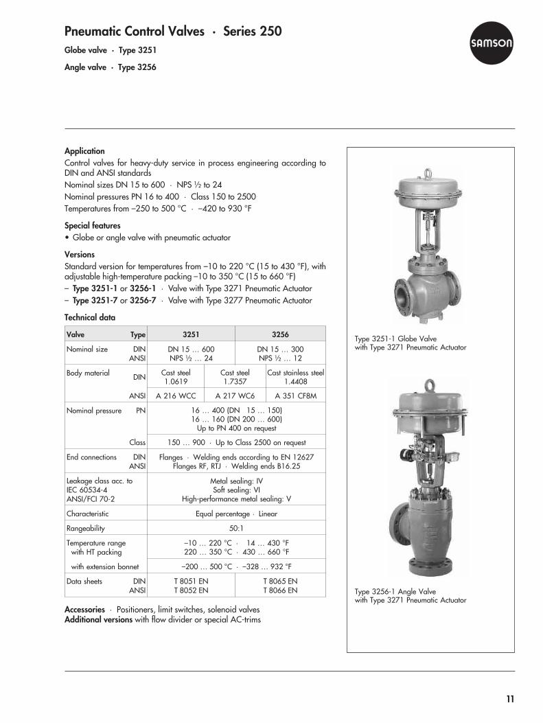
Pneumatic Control Valves · Series 250Globe valve · Type 3251
Angle valve · Type 3256
ApplicationControl valves for heavy-duty service in process engineering according toDIN and ANSI standardsNominal sizes DN 15 to 600 · NPS ½ to 24Nominal pressures PN 16 to 400 · Class 150 to 2500Temperatures from –250 to 500 °C · –420 to 930 °F
Special features• Globe or angle valve with pneumatic actuator
VersionsStandard version for temperatures from –10 to 220 °C (15 to 430 °F), withadjustable high-temperature packing –10 to 350 °C (15 to 660 °F)– Type 3251-1 or 3256-1 · Valve with Type 3271 Pneumatic Actuator– Type 3251-7 or 3256-7 · Valve with Type 3277 Pneumatic Actuator
Technical data
Valve Type 3251 3256
Nominal size DINANSI
DN 15 … 600NPS ½ … 24
DN 15 … 300NPS ½ … 12
Body material DIN Cast steel1.0619
Cast steel1.7357
Cast stainless steel1.4408
ANSI A 216 WCC A 217 WC6 A 351 CF8M
Nominal pressure PN 16 … 400 (DN 15 … 150)16 … 160 (DN 200 … 600)
Up to PN 400 on request
Class 150 … 900 · Up to Class 2500 on request
End connections DINANSI
Flanges · Welding ends according to EN 12627Flanges RF, RTJ · Welding ends B16.25
Leakage class acc. toIEC 60534-4ANSI/FCI 70-2
Metal sealing: IVSoft sealing: VI
High-performance metal sealing: V
Characteristic Equal percentage · Linear
Rangeability 50:1
Temperature rangewith HT packing
–10 … 220 °C · 14 … 430 °F220 … 350 °C · 430 … 660 °F
with extension bonnet –200 … 500 °C · –328 … 932 °F
Data sheets DINANSI
T 8051 ENT 8052 EN
T 8065 ENT 8066 EN
Accessories · Positioners, limit switches, solenoid valvesAdditional versions with flow divider or special AC-trims
Type 3251-1 Globe Valvewith Type 3271 Pneumatic Actuator
Type 3256-1 Angle Valvewith Type 3271 Pneumatic Actuator
11

Pneumatic Control Valves · Series 250Three-way valve · Type 3253
Globe valve · Type 3254
ApplicationControl valves for heavy-duty service in process engineering according toDIN and ANSI standards
Type 3253 · Pneumatic three-way valve
Valve Type 3253
Nominal size DN 15 … 400 · NPS ½ ...12
Body material DIN
ANSI
Cast ironEN-JL 1040
–
Cast steel1.0619
A 216 WCC
Cast stainlesssteel 1.4408A 351 CF8M
Nominal pressure PN 10 … 160* · Class 150 … 900*
End connections Flanges Acc. to DIN EN · Raised face, ring joint
Leakage class acc. toIEC 60534-4ANSI/FCI 70-2
Metal sealingClass I
Characteristic Linear
Rangeability 50:1
Temperature rangewith HT packingwith extension bonnet
–10 … 220 °C · 14 … 428 °F220 … 350 °C · 428 … 660 °F
–200 … 500 °C · –328 … 932 °F
Data sheets DIN: T 8055 EN · ANSI: T 8056 EN
* Higher pressures on request
Type 3254 · Pneumatic globe valve
Valve Type 3254
Nominal size DN 80 … 500 · NPS 3 … 20
Body material DIN
ANSI
Cast steel1.0619
A 216 WCC
Cast steel1.7357
A 217 WC6
Cast stainlesssteel
1.4408A 351 CF8M
Nominal pressure PN 16 … 400 · Class 150 … 2500
End connections Flanges · Welding ends acc. to EN 12627Flanges RF, RTJ · Welding ends ANSI B16.25
Leakage class acc. toIEC 60534-4ANSI/FCI 70-2
Metal sealing: IVSoft sealing: VI
High-performance metal sealing: V
Characteristic Equal percentage · Linear
Rangeability 50:1
Temperature rangewith HT packingwith extension bonnet
–10 … 220 °C · 14 … 430 °F220 … 350 °C · 428 … 660 °F
–200 … 500 °C · –328 … 932 °F
Data sheets DIN: T 8060 EN · ANSI: T 8061 EN
Type 3253-1 Three-way Valvewith Type 3271 Pneumatic Actuator
Type 3254-1 Globe Valvewith Type 3271 Pneumatic Actuator
12

Pneumatic Steam-converting Valves · Series 280Steam-converting valves · Type 3281, Type 3286 and Type 3284
ApplicationSteam-converting valves with globe-style and angle-style bodies for powerstations and thermal plants
Types 3281, 3286 and Type 3284 · Pneumatic steam-converting valves
Steam-converting valve Type 3281Globe Valve
Type 3286Angle Valve
Type 3284Globe Valve
Nominal size DN 50 … 200 50 … 300 100 … 400
NPS 2 … 8 2 … 12 4 … 16
Body material DIN Cast steel 1.0619 Cast steel 1.7357
ANSI A 216 WCC A 217 WC6
Nominal pressure PN 16 … 160 · Class 150 … 900
End connections Flanges · Welding ends
Leakage class acc. toIEC 60534-4ANSI/FCI 70-2
Metal sealing: IVHigh-performance metal sealing: V
Pressure-balanced: III
Characteristic Equal percentage · Linear
Rangeability 50:1
Temperature rangewith HT packing
Up to 220 °CUp to 350 °C
with extension bonnet Up to 400 °C Up to 500 °C
Data sheets T 8251 EN T 8254 EN
Type 3281-1 Steam-converting Valvewith Type 3271 Pneumatic Actuator
Type 3284-1 Steam-converting Valvewith Type 3271 Pneumatic Actuator
13
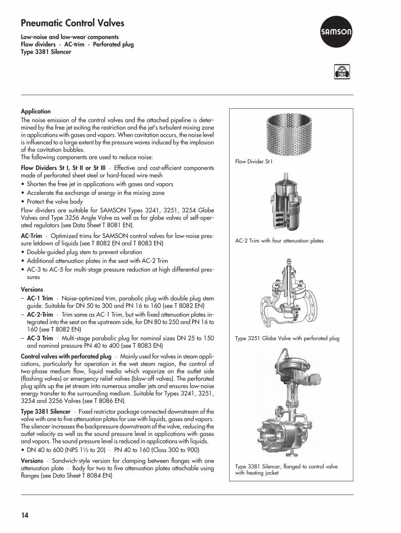
Pneumatic Control ValvesLow-noise and low-wear componentsFlow dividers · AC-trim · Perforated plugType 3381 Silencer
ApplicationThe noise emission of the control valves and the attached pipeline is deter-mined by the free jet exiting the restriction and the jet's turbulent mixing zonein applications with gases and vapors. When cavitation occurs, the noise levelis influenced to a large extent by the pressure waves induced by the implosionof the cavitation bubbles.The following components are used to reduce noise:
Flow Dividers St I, St II or St III · Effective and cost-efficient componentsmade of perforated sheet steel or hard-faced wire mesh• Shorten the free jet in applications with gases and vapors• Accelerate the exchange of energy in the mixing zone• Protect the valve bodyFlow dividers are suitable for SAMSON Types 3241, 3251, 3254 GlobeValves and Type 3256 Angle Valve as well as for globe valves of self-oper-ated regulators (see Data Sheet T 8081 EN).
AC-Trim · Optimized trims for SAMSON control valves for low-noise pres-sure letdown of liquids (see T 8082 EN and T 8083 EN)• Double-guided plug stem to prevent vibration• Additional attenuation plates in the seat with AC-2 Trim• AC-3 to AC-5 for multi-stage pressure reduction at high differential pres-
sures
Versions– AC-1 Trim · Noise-optimized trim, parabolic plug with double plug stem
guide. Suitable for DN 50 to 300 and PN 16 to 160 (see T 8082 EN)– AC-2-Trim · Trim same as AC-1 Trim, but with fixed attenuation plates in-
tegrated into the seat on the upstream side, for DN 80 to 250 and PN 16 to160 (see T 8082 EN)
– AC-3 Trim · Multi-stage parabolic plug for nominal sizes DN 25 to 150and nominal pressure PN 40 to 400 (see T 8083 EN)
Control valves with perforated plug · Mainly used for valves in steam appli-cations, particularly for operation in the wet steam region, the control oftwo-phase medium flow, liquid media which vaporize on the outlet side(flashing valves) or emergency relief valves (blow-off valves). The perforatedplug splits up the jet stream into numerous smaller jets and ensures low-noiseenergy transfer to the surrounding medium. Suitable for Types 3241, 3251,3254 and 3256 Valves (see T 8086 EN).
Type 3381 Silencer · Fixed restrictor package connected downstream of thevalve with one to five attenuation plates for use with liquids, gases and vapors.The silencer increases the backpressure downstream of the valve, reducing theoutlet velocity as well as the sound pressure level in applications with gasesand vapors. The sound pressure level is reduced in applications with liquids.• DN 40 to 600 (NPS 1½ to 20) · PN 40 to 160 (Class 300 to 900)
Versions · Sandwich-style version for clamping between flanges with oneattenuation plate · Body for two to five attenuation plates attachable usingflanges (see Data Sheet T 8084 EN)
Type 3381 Silencer, flanged to control valvewith heating jacket
Type 3251 Globe Valve with perforated plug
AC-2 Trim with four attenuation plates
Flow Divider St I
14

Pneumatic Control Valves · Series 240Diaphragm valve · Type 3345
On-off valve · Type 3351
Type 3345 Diaphragm ValveControl valve for viscous, corrosive and abrasive fluids according to• DIN, BS or ANSI standards• FDA-compliant version
Technical data for Type 3345
Version DIN ANSI
Nominal size DN 15 … 150 NPS ½ … 6
Body material EN-JL 1040 · EN-JS 10251.4408 · 1.4435
A 126 B · A 395A 351 CF8M · A 351 L
Maximum pressure 16 bar 230 psi
End connections Flanges · Threaded ends · Clamps · Welding ends
Diaphragm sealing/leakage class acc. toIEC 60534-4ANSI/FCI 70-2
Butyl · PTFE/EPM · EPDMClass VI
Characteristic Linear
Rangeability 30:1
Temperature range –30 … 160 °C –22 … 320 °F
Data sheet T 8031 EN
Type 3351 On-off ValveControl valve, optionally with bellows seal or extension bonnet, with tightshutoff for• Liquids, non-flammable gases and steam• DIN and ANSI standards
Technical data for Type 3351
Nominal size DN 15 … 100 · NPS ½ … 4
Body materialDIN Cast iron
EN-JL 1040Cast steel1.0619
Cast stainlesssteel
1.4408
ANSI – A 216 WCC A 351 CF8M
Nominal pressure PN 16 16 · 40
Class – 150 · 300
End connection DINANSI
Flanges Form B1 acc. to EN 1092Flanges RF
Leakage class acc. toIEC 60534-4ANSI/FCI 70-2
With both metal and soft sealingClass VI
Medium temperatures –50 … 250 °C · –20 … 482 °F
Data sheet DIN/ANSI: T 8039 EN
Type 3345-1Diaphragm Valve
Type 3345-1 Diaphragm Valve, DN 50Version for food processing industry
Type 3351-1 with extensionbonnet
Type 3351-1 On/off Valve
15
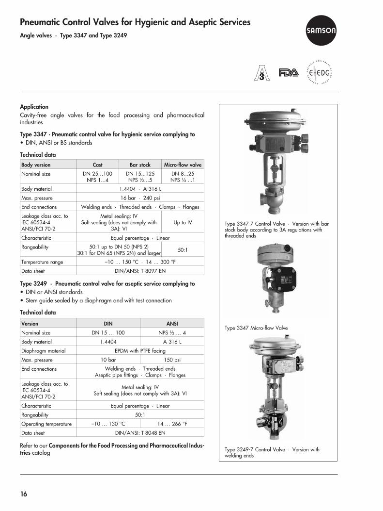
Pneumatic Control Valves for Hygienic and Aseptic ServicesAngle valves · Type 3347 and Type 3249
ApplicationCavity-free angle valves for the food processing and pharmaceuticalindustries
Type 3347 · Pneumatic control valve for hygienic service complying to• DIN, ANSI or BS standards
Technical data
Body version Cast Bar stock Micro-flow valve
Nominal size DN 25…100NPS 1...4
DN 15...125NPS ½…5
DN 8...25NPS ¼ ...1
Body material 1.4404 · A 316 L
Max. pressure 16 bar · 240 psi
End connections Welding ends · Threaded ends · Clamps · Flanges
Leakage class acc. toIEC 60534-4ANSI/FCI 70-2
Metal sealing: IVSoft sealing (does not comply with
3A): VIUp to IV
Characteristic Equal percentage · Linear
Rangeability 50:1 up to DN 50 (NPS 2)30:1 for DN 65 (NPS 2½) and larger 50:1
Temperature range –10 … 150 °C · 14 … 300 °F
Data sheet DIN/ANSI: T 8097 EN
Type 3249 · Pneumatic control valve for aseptic service complying to• DIN or ANSI standards• Stem guide sealed by a diaphragm and with test connection
Technical data
Version DIN ANSI
Nominal size DN 15 … 100 NPS ½ … 4
Body material 1.4404 A 316 L
Diaphragm material EPDM with PTFE facing
Max. pressure 10 bar 150 psi
End connections Welding ends · Threaded endsAseptic pipe fittings · Clamps · Flanges
Leakage class acc. toIEC 60534-4ANSI/FCI 70-2
Metal sealing: IVSoft sealing (does not comply with 3A): VI
Characteristic Equal percentage · Linear
Rangeability 50:1
Operating temperature –10 … 130 °C 14 … 266 °F
Data sheet DIN/ANSI: T 8048 EN
Refer to our Components for the Food Processing and Pharmaceutical Indus-tries catalog
Type 3347-7 Control Valve · Version with barstock body according to 3A regulations withthreaded ends
Type 3249-7 Control Valve · Version withwelding ends
Type 3347 Micro-flow Valve
16
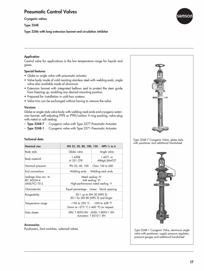
Pneumatic Control ValvesCryogenic valves
Type 3248
Type 3246 with long extension bonnet and circulation inhibitor
ApplicationControl valve for applications in the low temperature range for liquids andgases
Special features• Globe or angle valve with pneumatic actuator• Valve body made of cold-resisting stainless steel with welding ends, angle
valve also available made of aluminum• Extension bonnet with integrated bellows seal to protect the stem guide
from freezing up, enabling any desired mounting position• Prepared for installation in cold-box systems• Valve trim can be exchanged without having to remove the valve
VersionsGlobe or angle-style valve body with welding-neck ends and cryogenic exten-sion bonnet, self-adjusting PTFE or PTFE/carbon V-ring packing, valve plugwith metal or soft sealing– Type 3248-7 · Cryogenic valve with Type 3277 Pneumatic Actuator– Type 3248-1 · Cryogenic valve with Type 3271 Pneumatic Actuator
Technical data
Nominal size DN 25, 50, 80, 100, 150 · NPS ½ to 6
Body style Globe valve Angle valve
Body material 1.4308A 351 CF8
1.4571 orAlMg4,5MnF27
Nominal pressure PN 25, 40, 100 · Class 150 to 600
End connections Welding ends · Welding-neck ends
Leakage class acc. toIEC 60534-4ANSI/FCI 70-2
Metal sealing: IVSoft sealing: VI
High-performance metal sealing: V
Characteristic Equal percentage · Linear · Quick opening
Rangeability 50:1 up to DN 50 (NPS 2)30:1 for DN 80 (NPS 3) and larger
Temperature range –196 to 220 °C · –320 to 428 °FDown to –273 °C (–460 °F) on request
Data sheets DIN: T 8093 EN · ANSI: T 8093-1 ENActuators: T 8310-1 EN
AccessoriesPositioners, limit switches, solenoid valves
Type 3248-7 Cryogenic Valve, globe style,with positioner and additional handwheel
Type 3248-1 Cryogenic Valve, aluminum anglevalve with positioner, supply pressure regulator,pressure gauges and additional handwheel
17
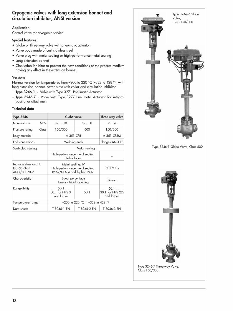
Cryogenic valves with long extension bonnet andcirculation inhibitor, ANSI version
ApplicationControl valve for cryogenic service
Special features• Globe or three-way valve with pneumatic actuator• Valve body made of cast stainless steel• Valve plug with metal sealing or high-performance metal sealing• Long extension bonnet• Circulation inhibitor to prevent the flow conditions of the process medium
having any effect in the extension bonnet
VersionsNormal version for temperatures from –200 to 220 °C (–328 to 428 °F) withlong extension bonnet, cover plate with collar and circulation inhibitor– Type 3246-1 · Valve with Type 3271 Pneumatic Actuator– Type 3246-7 · Valve with Type 3277 Pneumatic Actuator for integral
positioner attachment
Technical data
Type 3246 Globe valve Three-way valve
Nominal size NPS ½ … 10 ½ … 8 ½ ...6
Pressure rating Class 150/300 600 150/300
Body material A 351 CF8 A 351 CF8M
End connections Welding ends Flanges ANSI RF
Seat/plug sealing Metal sealing
High-performance metal sealingStellite facing –
Leakage class acc. toIEC 60534-4ANSI/FCI 70-2
Metal sealing: IVHigh-performance metal sealing:IV-S2/NPS 4 and higher: IV-S1
0.05 % CV
Characteristic Equal percentageLinear · Quick-opening Linear
Rangeability 50:130:1 for NPS 3
and larger50:1
50:130:1 for NPS 2½
and larger
Temperature range –200 to 220 °C · –328 to 428 °F
Data sheets T 8046-1 EN T 8046-2 EN T 8046-3 EN
Type 3246-1 Globe Valve, Class 600
Type 3246-7 GlobeValve,Class 150/300
Type 3246-7 Three-way Valve,Class 150/300
18

Pneumatic Butterfly ValvesButterfly valves · Type 3331, Type 3335 and Type 3237
Butterfly valves · Pfeiffer Type BR 10a, BR 10e and BR 14b/31a
High-pressure butterfly valve · LEUSCH Type LTR 43
ApplicationControl valves for process engineering and industrial applications
Versions– Type 3331 · Swing-through or angle-seated disc for liquids, vapors and
gases with Type BR 31a Pneumatic Actuator– Type 3335 · Shut-off valve, Type BR 31a Pneumatic Actuator, with EPDM
or PTFE seat ring, optionally with PFA-lined disc– Type 3237 · Swing-through or step-seated butterfly valve with Type 3271
or Type 3277 Pneumatic Actuator
Technical data
Type 3331 3335 3237
Nominalsize
DNNPS
50 … 4002 … 16
50 … 3002 … 12
500 … 100020 … 40
Bodymaterial
DINCast steel1.06191.4408
Cast ironEN-JL 1040
Sph. graphite ironEN-GLS-400-18-LT
1.06191.04251.45811.4571
ANSI A 216 WCCA351 CF8M –
Nominalpressure
PN 10 … 40ISO 20, 50 10 · 16 6 … 16
Class 150 · 300 –
Body style Sandwich Sandwich · Lug-type
DiscMaterial Stainless steel Sph. graphite iron
Stainless steelCast steel
Stainless steel
Sealing Metal Soft Metal
Leakage � 1 % A acc. toDIN EN 12266-1
� 0.5� 0.05
Opening angle 90° · 70° 90° 70°
Throttlingservice up to 70° Partly for
25 … 60° 70°
Rangeability 50:1 Quick opening 50:1
Temperaturerange
–10 … 400 °C –10 … 150 °C –10 … 220 °C
14 … 752 °F 14 … 302 °F 14 … 428 °F
Actuator Type BR 31a BR 31a 3271/3277
Data sheets T 8227 EN T 8220 EN T 8225 EN
Accessories · Positioners, limit switches, solenoid valves
Type 3331/BR 31a Pneumatic Butterfly Valve
Type 3335/BR 31a Pneumatic Shut-off Valve
Type 3237/3271 Swing-through or Step-seatedButterfly Valve
19
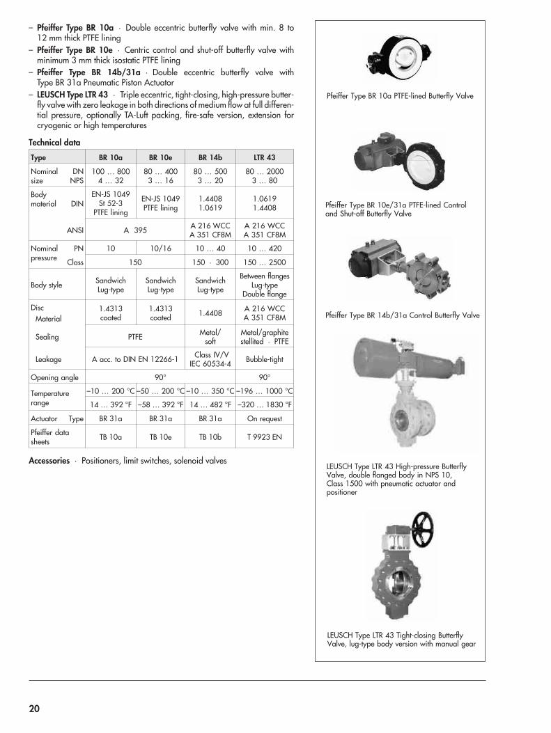
– Pfeiffer Type BR 10a · Double eccentric butterfly valve with min. 8 to12 mm thick PTFE lining
– Pfeiffer Type BR 10e · Centric control and shut-off butterfly valve withminimum 3 mm thick isostatic PTFE lining
– Pfeiffer Type BR 14b/31a · Double eccentric butterfly valve withType BR 31a Pneumatic Piston Actuator
– LEUSCH Type LTR 43 · Triple eccentric, tight-closing, high-pressure butter-fly valve with zero leakage in both directions of medium flow at full differen-tial pressure, optionally TA-Luft packing, fire-safe version, extension forcryogenic or high temperatures
Technical data
Type BR 10a BR 10e BR 14b LTR 43
Nominalsize
DNNPS
100 … 8004 … 32
80 … 4003 … 16
80 … 5003 … 20
80 … 20003 … 80
Bodymaterial DIN
EN-JS 1049St 52-3
PTFE lining
EN-JS 1049PTFE lining
1.44081.0619
1.06191.4408
ANSI A 395 A 216 WCCA 351 CF8M
A 216 WCCA 351 CF8M
Nominalpressure
PN 10 10/16 10 … 40 10 … 420
Class 150 150 · 300 150 … 2500
Body style SandwichLug-type
SandwichLug-type
SandwichLug-type
Between flangesLug-type
Double flange
DiscMaterial
1.4313coated
1.4313coated 1.4408 A 216 WCC
A 351 CF8M
Sealing PTFE Metal/soft
Metal/graphitestellited · PTFE
Leakage A acc. to DIN EN 12266-1 Class IV/VIEC 60534-4 Bubble-tight
Opening angle 90° 90°
Temperaturerange
–10 … 200 °C –50 … 200 °C –10 … 350 °C –196 … 1000 °C
14 … 392 °F –58 … 392 °F 14 … 482 °F –320 … 1830 °F
Actuator Type BR 31a BR 31a BR 31a On request
Pfeiffer datasheets TB 10a TB 10e TB 10b T 9923 EN
Accessories · Positioners, limit switches, solenoid valves
Pfeiffer Type BR 10a PTFE-lined Butterfly Valve
Pfeiffer Type BR 10e/31a PTFE-lined Controland Shut-off Butterfly Valve
Pfeiffer Type BR 14b/31a Control Butterfly Valve
LEUSCH Type LTR 43 High-pressure ButterflyValve, double flanged body in NPS 10,Class 1500 with pneumatic actuator andpositioner
LEUSCH Type LTR 43 Tight-closing ButterflyValve, lug-type body version with manual gear
20
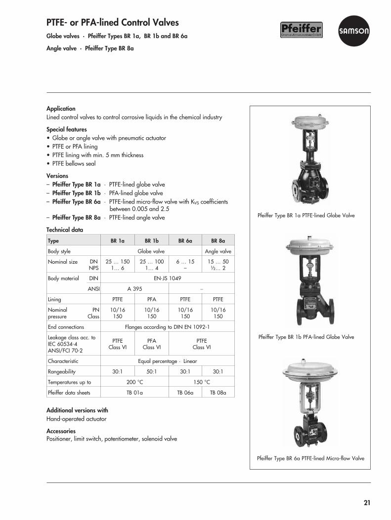
PTFE- or PFA-lined Control ValvesGlobe valves · Pfeiffer Types BR 1a, BR 1b and BR 6a
Angle valve · Pfeiffer Type BR 8a
ApplicationLined control valves to control corrosive liquids in the chemical industry
Special features• Globe or angle valve with pneumatic actuator• PTFE or PFA lining• PTFE lining with min. 5 mm thickness• PTFE bellows seal
Versions– Pfeiffer Type BR 1a · PTFE-lined globe valve– Pfeiffer Type BR 1b · PFA-lined globe valve– Pfeiffer Type BR 6a · PTFE-lined micro-flow valve with KVS coefficients
between 0.005 and 2.5– Pfeiffer Type BR 8a · PTFE-lined angle valve
Technical data
Type BR 1a BR 1b BR 6a BR 8a
Body style Globe valve Angle valve
Nominal size DNNPS
25 … 1501… 6
25 … 1001… 4
6 … 15–
15 … 50½… 2
Body material DIN EN-JS 1049
ANSI A 395 �
Lining PTFE PFA PTFE PTFE
Nominalpressure
PNClass
10/16150
10/16150
10/16150
10/16150
End connections Flanges according to DIN EN 1092-1
Leakage class acc. toIEC 60534-4ANSI/FCI 70-2
PTFEClass VI
PFAClass VI
PTFEClass VI
Characteristic Equal percentage · Linear
Rangeability 30:1 50:1 30:1 30:1
Temperatures up to 200 °C 150 °C
Pfeiffer data sheets TB 01a TB 06a TB 08a
Additional versions withHand-operated actuator
AccessoriesPositioner, limit switch, potentiometer, solenoid valve
Pfeiffer Type BR 1a PTFE-lined Globe Valve
Pfeiffer Type BR 1b PFA-lined Globe Valve
Pfeiffer Type BR 6a PTFE-lined Micro-flow Valve
21

Ball Valves and Pigging ValvesLined ball valves · Pfeiffer Types BR 20a and BR 20b
Stainless steel ball valves · Pfeiffer Types BR 22a and BR 26
Pigging valves · Pfeiffer Types BR 28 and BR 29
Sampling valve · Pfeiffer Type BR 27
ApplicationTight-closing lined valves for process engineering and industrial applications,especially for use with corrosive media– Pfeiffer Type BR 20a · PTFE-lined ball valve– Pfeiffer Type BR 20b · PFA-lined ball valve
Type BR 20a BR 20b
Style/end connections Flanges Flanges
Nominal size DN 25 … 150 25 … 100
Body material EN-JS 1049 EN-JS 1049
Lining PTFE white PFA
Nominal pressure PN 16 16
Disc PTFE-coated PFA-coated
Leakage rate A acc. to DIN EN 12266-1
Temperatures –10 … 200 °C –10 … 200 °C
Pfeiffer data sheets TB 20a TB 20b
ApplicationTight-closing ball valves for process engineering and industrial applications,especially for use with corrosive media– Pfeiffer Type BR 22a · Stainless steel tank bottom valve– Pfeiffer Type BR 26 · Stainless steel ball valve
Type BR 22a BR 26
Nominal size DN 50 … 150 15 … 150
NPS 2 … 6 ½ … 4
Body material DIN 1.4408 · 1.4571 · 1.4581 1.4408 · 1.4571
ANSI F 316 Ti A 315 CF8M
Nominalpressure
PN 16 … 40 16 … 40
Class 150/300 150/300
Connecting flanges Acc. to EN 1092 Acc. to EN 1092
Ball sealing 1.4571 with PTFE TFM
Leakage rate A acc. to DIN EN 12266-1
Temperatures –10 … 200 °C –10 … 200 °C
Pfeiffer data sheets TB 22a TB 26
Additional versions withHand-operated actuator
AccessoriesPositioner, limit switches, potentiometer, solenoid valve
Pfeiffer Type BR 20a PTFE-lined Ball Valve
Pfeiffer Type BR 22a Stainless Steel Tank BottomValve
Pfeiffer Type BR 26/31a Stainless SteelBall Valve
22
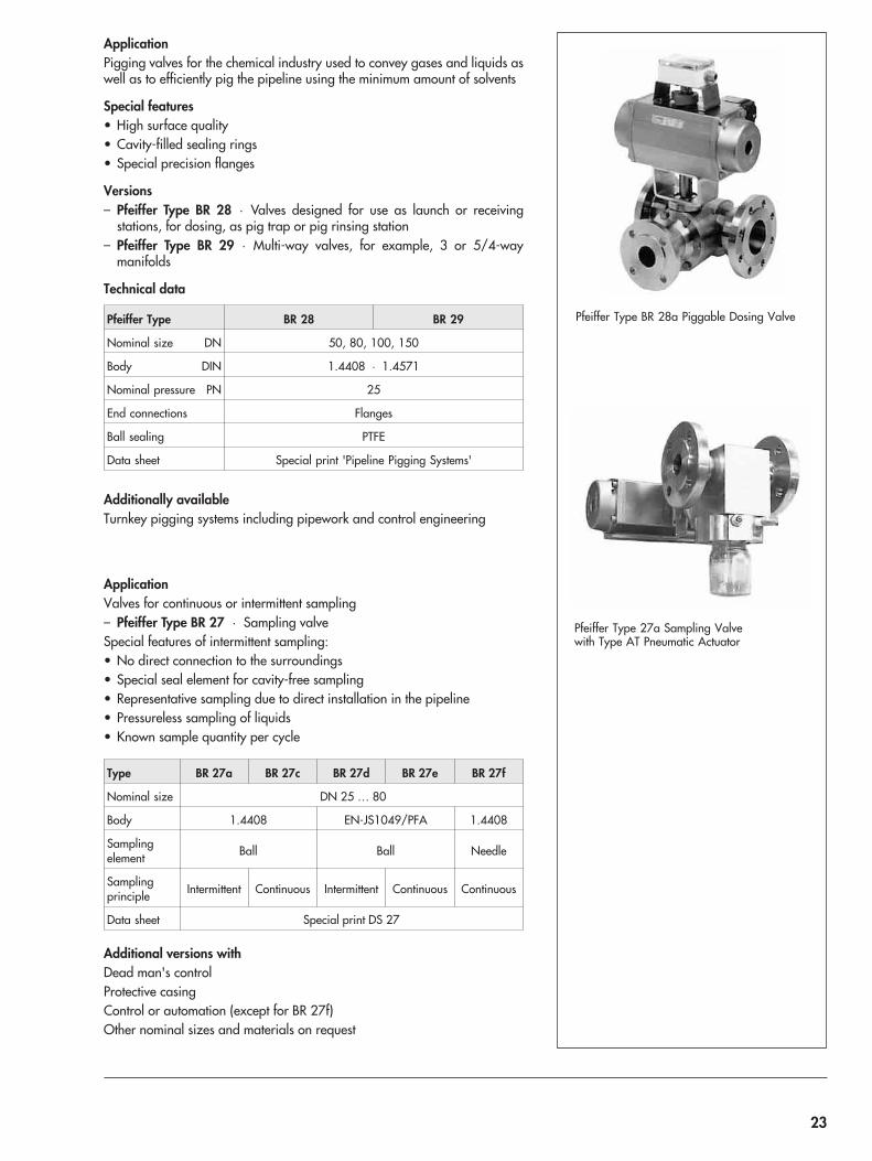
ApplicationPigging valves for the chemical industry used to convey gases and liquids aswell as to efficiently pig the pipeline using the minimum amount of solvents
Special features• High surface quality• Cavity-filled sealing rings• Special precision flanges
Versions– Pfeiffer Type BR 28 · Valves designed for use as launch or receiving
stations, for dosing, as pig trap or pig rinsing station– Pfeiffer Type BR 29 · Multi-way valves, for example, 3 or 5/4-way
manifolds
Technical data
Pfeiffer Type BR 28 BR 29
Nominal size DN 50, 80, 100, 150
Body DIN 1.4408 · 1.4571
Nominal pressure PN 25
End connections Flanges
Ball sealing PTFE
Data sheet Special print 'Pipeline Pigging Systems'
Additionally availableTurnkey pigging systems including pipework and control engineering
ApplicationValves for continuous or intermittent sampling– Pfeiffer Type BR 27 · Sampling valveSpecial features of intermittent sampling:• No direct connection to the surroundings• Special seal element for cavity-free sampling• Representative sampling due to direct installation in the pipeline• Pressureless sampling of liquids• Known sample quantity per cycle
Type BR 27a BR 27c BR 27d BR 27e BR 27f
Nominal size DN 25 … 80
Body 1.4408 EN-JS1049/PFA 1.4408
Samplingelement Ball Ball Needle
Samplingprinciple Intermittent Continuous Intermittent Continuous Continuous
Data sheet Special print DS 27
Additional versions withDead man's controlProtective casingControl or automation (except for BR 27f)Other nominal sizes and materials on request
Pfeiffer Type BR 28a Piggable Dosing Valve
Pfeiffer Type 27a Sampling Valvewith Type AT Pneumatic Actuator
23
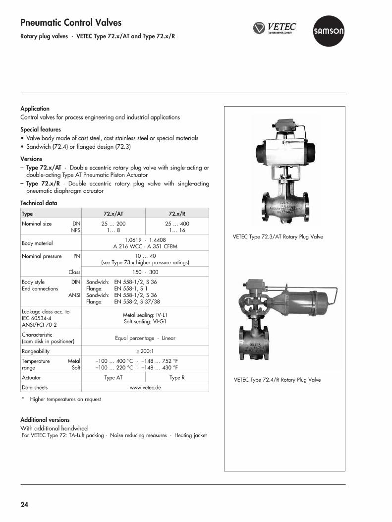
Pneumatic Control ValvesRotary plug valves · VETEC Type 72.x/AT and Type 72.x/R
ApplicationControl valves for process engineering and industrial applications
Special features• Valve body made of cast steel, cast stainless steel or special materials• Sandwich (72.4) or flanged design (72.3)
Versions– Type 72.x/AT · Double eccentric rotary plug valve with single-acting or
double-acting Type AT Pneumatic Piston Actuator– Type 72.x/R · Double eccentric rotary plug valve with single-acting
pneumatic diaphragm actuator
Technical data
Type 72.x/AT 72.x/R
Nominal size DNNPS
25 … 2001… 8
25 … 4001… 16
Body material 1.0619 · 1.4408A 216 WCC · A 351 CF8M
Nominal pressure PN 10 … 40(see Type 73.x higher pressure ratings)
Class 150 · 300
Body styleEnd connections
DIN
ANSI
Sandwich: EN 558-1/2, S 36Flange: EN 558-1, S 1Sandwich: EN 558-1/2, S 36Flange: EN 558-2, S 37/38
Leakage class acc. toIEC 60534-4ANSI/FCI 70-2
Metal sealing: IV-L1Soft sealing: VI-G1
Characteristic(cam disk in positioner) Equal percentage · Linear
Rangeability � 200:1
Temperaturerange
MetalSoft
–100 … 400 °C · –148 … 752 °F–100 … 220 °C · –148 … 430 °F
Actuator Type AT Type R
Data sheets www.vetec.de
* Higher temperatures on request
Additional versionsWith additional handwheelFor VETEC Type 72: TA-Luft packing · Noise reducing measures · Heating jacket
VETEC Type 72.3/AT Rotary Plug Valve
VETEC Type 72.4/R Rotary Plug Valve
24
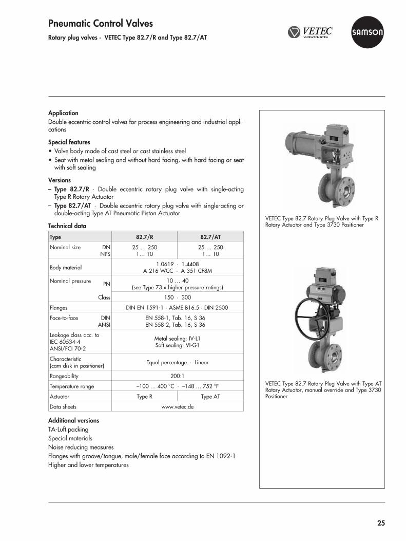
Pneumatic Control ValvesRotary plug valves · VETEC Type 82.7/R and Type 82.7/AT
ApplicationDouble eccentric control valves for process engineering and industrial appli-cations
Special features• Valve body made of cast steel or cast stainless steel• Seat with metal sealing and without hard facing, with hard facing or seat
with soft sealing
Versions– Type 82.7/R · Double eccentric rotary plug valve with single-acting
Type R Rotary Actuator– Type 82.7/AT · Double eccentric rotary plug valve with single-acting or
double-acting Type AT Pneumatic Piston Actuator
Technical data
Type 82.7/R 82.7/AT
Nominal size DNNPS
25 … 2501… 10
25 … 2501… 10
Body material 1.0619 · 1.4408A 216 WCC · A 351 CF8M
Nominal pressure PN 10 … 40(see Type 73.x higher pressure ratings)
Class 150 · 300
Flanges DIN EN 1591-1 · ASME B16.5 · DIN 2500
Face-to-face DINANSI
EN 558-1, Tab. 16, S 36EN 558-2, Tab. 16, S 36
Leakage class acc. toIEC 60534-4ANSI/FCI 70-2
Metal sealing: IV-L1Soft sealing: VI-G1
Characteristic(cam disk in positioner) Equal percentage · Linear
Rangeability 200:1
Temperature range –100 … 400 °C · –148 … 752 °F
Actuator Type R Type AT
Data sheets www.vetec.de
Additional versionsTA-Luft packingSpecial materialsNoise reducing measuresFlanges with groove/tongue, male/female face according to EN 1092-1Higher and lower temperatures
VETEC Type 82.7 Rotary Plug Valve with Type RRotary Actuator and Type 3730 Positioner
VETEC Type 82.7 Rotary Plug Valve with Type ATRotary Actuator, manual override and Type 3730Positioner
25
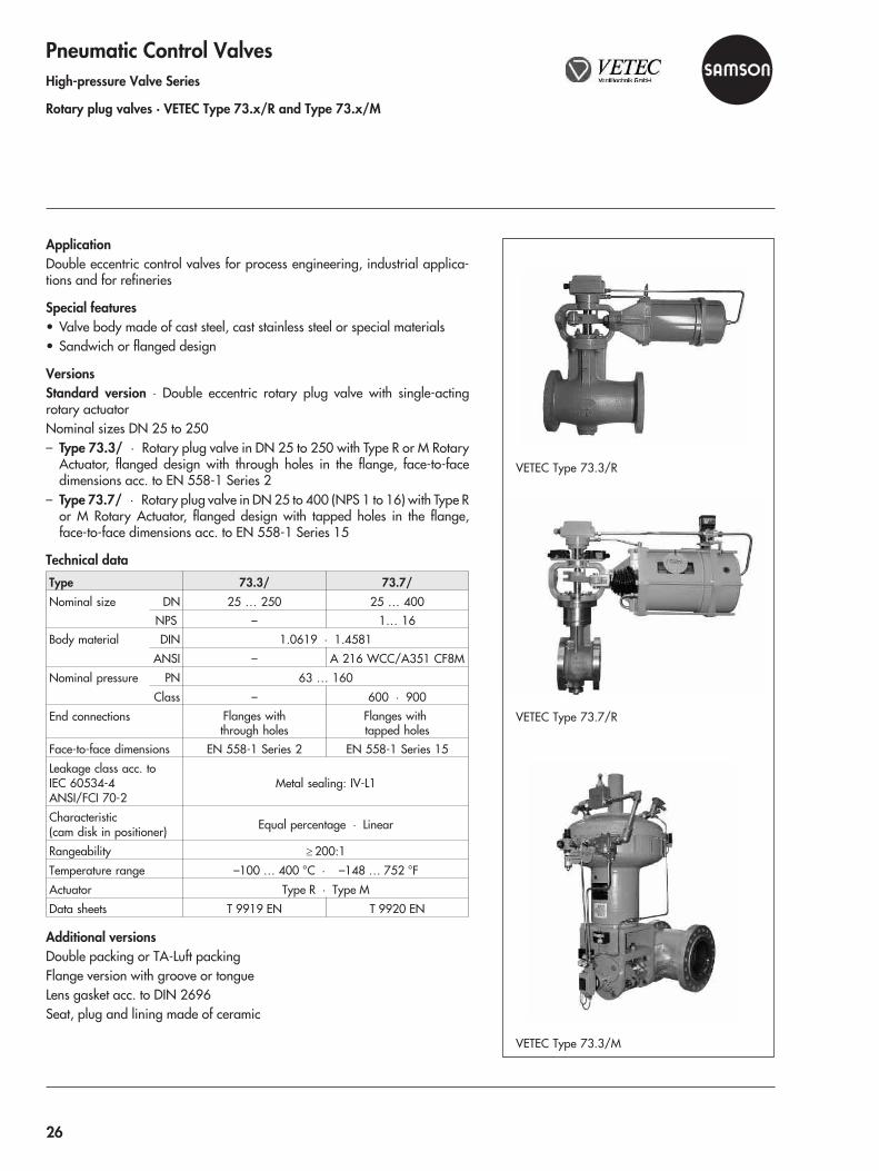
Pneumatic Control ValvesHigh-pressure Valve Series
Rotary plug valves · VETEC Type 73.x/R and Type 73.x/M
ApplicationDouble eccentric control valves for process engineering, industrial applica-tions and for refineries
Special features• Valve body made of cast steel, cast stainless steel or special materials• Sandwich or flanged design
VersionsStandard version · Double eccentric rotary plug valve with single-actingrotary actuatorNominal sizes DN 25 to 250– Type 73.3/ · Rotary plug valve in DN 25 to 250 with Type R or M Rotary
Actuator, flanged design with through holes in the flange, face-to-facedimensions acc. to EN 558-1 Series 2
– Type 73.7/ · Rotary plug valve in DN 25 to 400 (NPS 1 to 16) with Type Ror M Rotary Actuator, flanged design with tapped holes in the flange,face-to-face dimensions acc. to EN 558-1 Series 15
Technical data
Type 73.3/ 73.7/Nominal size DN 25 … 250 25 … 400
NPS – 1… 16Body material DIN 1.0619 · 1.4581
ANSI – A 216 WCC/A351 CF8M
Nominal pressure PN 63 … 160
Class – 600 · 900
End connections Flanges withthrough holes
Flanges withtapped holes
Face-to-face dimensions EN 558-1 Series 2 EN 558-1 Series 15
Leakage class acc. toIEC 60534-4ANSI/FCI 70-2
Metal sealing: IV-L1
Characteristic(cam disk in positioner) Equal percentage · Linear
Rangeability � 200:1
Temperature range –100 … 400 °C · –148 … 752 °F
Actuator Type R · Type M
Data sheets T 9919 EN T 9920 EN
Additional versionsDouble packing or TA-Luft packingFlange version with groove or tongueLens gasket acc. to DIN 2696Seat, plug and lining made of ceramic
VETEC Type 73.3/R
VETEC Type 73.7/R
VETEC Type 73.3/M
26

Pneumatic Control ValvesVETEC Type 72.x/AT DVGW and Type 72.x/MN DVGW
Control and quick-acting shut-off valves for gases
ApplicationControl valves for control equipment subject to special safety requirementsapplicable to gas supply.For neutral gases according to the working paper G 260/1 issued by DVGW(German Technical and Scientific Association on Gas and Water)
Special features• Type 72.3 Control and Quick-acting Shut-off Valve in flanged design or
Type 72.4 in sandwich design• Single-acting pneumatic actuator Type AT or Type MN• Mounted pilot valve (3/2-way solenoid valve) and fast venting• TA-Luft packing• DVGW typetesting according to DIN EN 161
Versions– Type 72.x/AT DVGW · Double eccentric rotary plug valve with
single-acting or double-acting Type AT Pneumatic Piston Actuator– Type 72.x/MN DVGW · Double eccentric rotary plug valve with
single-acting pneumatic diaphragm actuator
Technical data
Type 72.x/AT 72.x/MN
Nominal size DNNPS
25 … 2001… 8
25 … 2001… 8
Body material 1.0619 · 1.4581A 216 WCC · A 351 CF8M
Nominal pressure PN 10 … 40
Class 150 · 300
Body styleEnd connections
DIN
ANSI
Flange: EN 558-1, Tab. 12, S 1Sandwich: EN 558-1, Tab. 16, S 36Flange: EN 558-2, Tab. 12, S 37/38Sandwich: EN 558-2, Tab. 16, S 36
Leakage class acc. toIEC 60534-4ANSI/FCI 70-2
Metal sealing: IV-L1Soft sealing: VI-G1
Characteristic(cam disk in positioner) Equal percentage · Linear
Rangeability � 200:1
Temperaturerange
Medium –20 … 150 °C · –148 … 752 °FAmbient –20 … 60 °C · –148 … 430 °F
Actuator Type AT Type R
Data sheets www.vetec.de
Additional versionsNoise reducing measures · Special materials · Flange with groove accord-ing to EN 1092-1/RTJ · Strainer installed upstream of the valve
VETEC Type 72.3/MN DVGW Rotary PlugValve in sandwich design
VETEC Type 72.3/AT DVGW Rotary Plug Valvein flanged design
27

Pneumatic Control ValvesSegmented ball valve · Type 3310/BR 31a
ApplicationControl valves for process engineering and industrial applications
Special features• Valve body in flanged design made of cast stainless steel or special alloys• Segmented ball with soft or metal sealing
Versions– Type 3310/AT (BR 31a) · Segmented ball valve with single-acting or dou-
ble-acting Type BR 31a Pneumatic Piston Actuator– Type 3310/3278 · Segmented ball valve with single-acting Type 3278
Rotary Actuator
Technical data
Type 3310 DIN ANSI
Nominal size DN 25 … 300 NPS 1 … 12
Body material A 216 WCC · A 351 CF8M
Nominal pressure PN PN 40 Class 300
End connections Flanges Flanges according toANSI B16.5
Leakage class acc. toIEC 60534-4ANSI/FCI 70-2
Soft sealing: VI · Metal sealing: IV
Characteristic Equal percentage · Linear
Rangeability � 100:1
Temperature ranges
Standard version –29 … 220 °C –20 … 430 °F
With extension bonnet –29 … 427 °C –20 … 800 °F
With extension bonnet(cast st. steel version) –46 … 220 °C –51 … 430 °F
Actuator Type BR 31a · Type 3278
Data sheets T 8222 EN · T 9929 EN · T 8321 EN
Additional versionsDouble packing with or without leak monitoringExtension bonnet for medium temperatures from –29 to 427 °C (–20 to800 °F)Reduced KVS coefficients by installing upstream or downstream reducersManual override or with additional manual overrideHeating jacket
Type 3310/BR 31a Segmented Ball Valve
Cutaway model of Type 3310 with Type BR 31aPneumatic Rotary Actuator and positioner
28
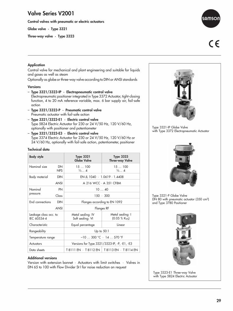
Valve Series V2001Control valves with pneumatic or electric actuators
Globe valve · Type 3321
Three-way valve · Type 3323
ApplicationControl valve for mechanical and plant engineering and suitable for liquidsand gases as well as steamOptionally as globe or three-way valve according to DIN or ANSI standards
Versions– Type 3321/3323-IP · Electropneumatic control valve
Electropneumatic positioner integrated in Type 3372 Actuator, tight-closingfunction, 4 to 20 mA reference variable, max. 6 bar supply air, fail-safeaction
– Type 3321/3323-P · Pneumatic control valvePneumatic actuator with fail-safe action
– Type 3321/3323-E1 · Electric control valveType 5824 Electric Actuator for 230 or 24 V/50 Hz, 120 V/60 Hz,optionally with positioner and potentiometer
– Type 3321/3323-E3 · Electric control valveType 3374 Electric Actuator for 230 or 24 V/50 Hz, 120 V/60 Hz or24 V/60 Hz, optionally with fail-safe action, potentiometer, positioner
Technical data
Body style Type 3321Globe Valve
Type 3323Three-way Valve
Nominal size DNNPS
15 … 100½… 4
15 … 100½… 4
Body material DIN EN-JL 1040 · 1.0619 · 1.4408
ANSI A 216 WCC · A 351 CF8M
Nominalpressure
PN 10 … 40
Class 150 · 300
End connections DIN Flanges according to EN 1092
ANSI Flanges RF
Leakage class acc. toIEC 60534-4
Metal sealing: IVSoft sealing: VI
Metal sealing: I(0.05 % KVS)
Characteristic Equal percentage Linear
Rangeability Up to 50:1
Temperature range –10 … 300 °C · 14 … 570 °F
Actuators Versions for Type 3321/3323-IP, -P, -E1, -E3
Data sheets T 8111 EN · T 8112 EN T 8113 EN · T 8114 EN
Additional versionsVersion with extension bonnet · Actuators with limit switches · Valves inDN 65 to 100 with Flow Divider St I for noise reduction on request
Type 3321-IP Globe Valvewith Type 3372 Electropneumatic Actuator
Type 3321-P Globe ValveDN 80 with pneumatic actuator (350 cm²)and Type 3780 Positioner
Type 3323-E1 Three-way Valvewith Type 5824 Electric Actuator
29

Valve Series V2001Control valves with pneumatic or electric actuators
Globe valve for heat transfer oil · Type 3531
Three-way valve for heat transfer oil · Type 3535
ApplicationControl valves designed for heat transfer systems with organic heat transfermedia according to DIN 4754Optionally as globe or three-way valve according to DIN or ANSI standards
Versions– Type 3531/3535-IP · Electropneumatic control valve for heat transfer
oilElectropneumatic positioner integrated in Type 3372 Actuator, tight-closingfunction, 4 to 20 mA reference variable, max. 6 bar supply air, fail-safeaction
– Type 3531/3535-P · Pneumatic control valve for heat transfer oilPneumatic actuator with fail-safe action
– Type 3531/3535-E1 · Electric control valve for heat transfer oilType 5824 Electric Actuator for 230 or 24 V/50 Hz, 120 V/60 Hz, option-ally with positioner and potentiometer
– Type 3531/3535-E3 · Electric control valve for heat transfer oilType 3374 Electric Actuator for 230 or 24 V/50 Hz, 120 V/60 Hz or 24V/60 Hz, optionally with fail-safe action, potentiometer, positioner
Technical data
Body style Type 3531Globe Valve
Type 3535Three-way Valve
Nominal size DNNPS
15 … 80½… 3
Body material DINANSI
EN-JS 1049 · 1.4408A 216 WCC · A 351 CF8M
Nominalpressure
PNClass
16 · 25150
End connections DIN Flanges acc. to EN 1092
ANSI Flanges RF
Leakage class acc. toIEC 60534-4 Metal sealing: IV
Metal sealing: I(0.05 % KVS)
Characteristic Equal percentage Linear
Rangeability 50:1 Up to 50:1
Temperature range –10 … 350 °C · –20 … 660 °FDown to –70 °C (–95 °F) on request
Recommended actuators Versions for Type 3531/3535 -IP, -P, -E1, -E3
Data sheets T 8131 EN · T 8132 EN T 8135 EN · T 8136 EN
Additional versionsActuators with a maximum of two limit switches
Type 3531-P Globe Valve for Heat Transfer Oilwith pneumatic actuator andType 4744-2 Electric Limit Switch
Type 3535-E3 Three-way Valve for Heat TransferOil with Type 3374 Electric Actuator
30
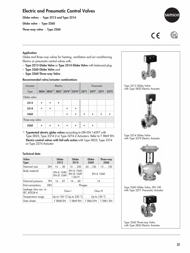
Electric and Pneumatic Control ValvesGlobe valves · Type 3213 and Type 3214
Globe valve · Type 3260
Three-way valve · Type 3260
ApplicationGlobe and three-way valves for heating, ventilation and air-conditioningElectric or pneumatic control valves with:– Type 3213 Globe Valve or Type 3214 Globe Valve with balanced plug– Type 3260 Globe Valve and– Type 3260 Three-way Valve
Recommended valve/actuator combinations
Actuator Electric Pneumatic
Type 5824 58251) 5857 33741) 32741) 3271 3277 3371 3372
Globe valve
3213 • • •
3214 • • • •
3260 • • • • • •
Three-way valve
3260 • • • • • • •
1) Typetested electric globe valves according to DIN EN 145 7 withType 5825, Type 3374-2 or Type 3274-2 Actuators. Refer to T 5869 ENElectric control valves with fail-safe action with Type 5825, Type 3374or Type 3274 Actuator
Technical data
ValveType
Globe3213
Globe3214
Globe3260
Three-way3260
Nominal size DN 15 … 50 15 … 250 65 ...150 15 … 150
Body material EN-JL 1040EN-JS 1049
EN-JL 1040EN-JS 1049
1.0619EN-JL 1040
Nominal pressure PN 16 · 25 16 … 40 16
End connections DIN Flanges
Leakage class acc. toIEC 60534-4 Class I Class IV
Temperature range Up to 150 °C Up to 220 °C Up to 150 °C
Data sheets T 5868 EN · T 5869 EN T 5862 EN T 5861 EN
Type 3213 Globe Valvewith Type 5825 Electric Actuator
Type 3214 Globe Valvewith Type 3374 Electric Actuator
Type 3260 Globe Valve, DN 100with Type 3271 Pneumatic Actuator
Type 3260 Three-way Valvewith Type 5824 Electric Actuator
9
31
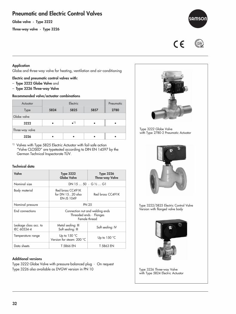
Pneumatic and Electric Control ValvesGlobe valve · Type 3222
Three-way valve · Type 3226
ApplicationGlobe and three-way valve for heating, ventilation and air-conditioning
Electric and pneumatic control valves with:– Type 3222 Globe Valve and– Type 3226 Three-way Valve
Recommended valve/actuator combinations
Actuator Electric Pneumatic
Type 5824 5825 5857 2780
Globe valve
3222 • •1) • •
Three-way valve
3226 • • • •
1) Valves with Type 5825 Electric Actuator with fail-safe action“Valve CLOSED” are typetested according to DIN EN 14597 by theGerman Technical Inspectorate TÜV.
Technical data
Valve Type 3222Globe Valve
Type 3226Three-way Valve
Nominal size DN 15 … 50 · G ½ … G1
Body material Red brass CC491Kfor DN 15...20 also
EN-JS 1049Red brass CC491K
Nominal pressure PN 25
End connections Connection nut and welding endsThreaded ends · Flanges
Female thread
Leakage class acc. toIEC 60534-4
Metal sealing: IIISoft sealing: III Soft sealing: IV
Temperature range Up to 150 °CVersion for steam: 200 °C Up to 150 °C
Data sheets T 5866 EN T 5863 EN
Additional versionsType 3222 Globe Valve with pressure-balanced plug · On requestType 3226 also available as DVGW version in PN 10
Type 3222 Globe Valvewith Type 2780-2 Pneumatic Actuator
Type 3222/5825 Electric Control ValveVersion with flanged valve body
Type 3226 Three-way Valvewith Type 5824 Electric Actuator
32
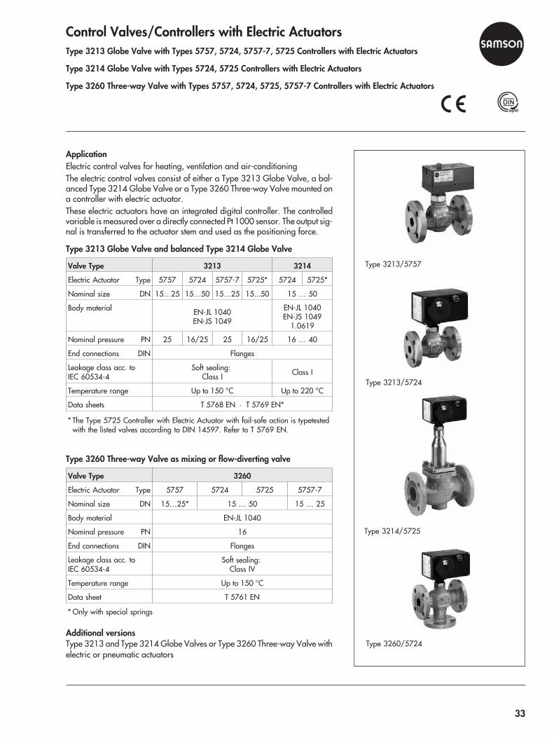
Control Valves/Controllers with Electric ActuatorsType 3213 Globe Valve with Types 5757, 5724, 5757-7, 5725 Controllers with Electric Actuators
Type 3214 Globe Valve with Types 5724, 5725 Controllers with Electric Actuators
Type 3260 Three-way Valve with Types 5757, 5724, 5725, 5757-7 Controllers with Electric Actuators
ApplicationElectric control valves for heating, ventilation and air-conditioningThe electric control valves consist of either a Type 3213 Globe Valve, a bal-anced Type 3214 Globe Valve or a Type 3260 Three-way Valve mounted ona controller with electric actuator.These electric actuators have an integrated digital controller. The controlledvariable is measured over a directly connected Pt 1000 sensor. The output sig-nal is transferred to the actuator stem and used as the positioning force.
Type 3213 Globe Valve and balanced Type 3214 Globe Valve
Valve Type 3213 3214
Electric Actuator Type 5757 5724 5757-7 5725* 5724 5725*
Nominal size DN 15…25 15…50 15…25 15...50 15 … 50
Body material EN-JL 1040EN-JS 1049
EN-JL 1040EN-JS 1049
1.0619
Nominal pressure PN 25 16/25 25 16/25 16 … 40
End connections DIN Flanges
Leakage class acc. toIEC 60534-4
Soft sealing:Class I Class I
Temperature range Up to 150 °C Up to 220 °C
Data sheets T 5768 EN · T 5769 EN*
* The Type 5725 Controller with Electric Actuator with fail-safe action is typetestedwith the listed valves according to DIN 14597. Refer to T 5769 EN.
Type 3260 Three-way Valve as mixing or flow-diverting valve
Valve Type 3260
Electric Actuator Type 5757 5724 5725 5757-7
Nominal size DN 15…25* 15 … 50 15 … 25
Body material EN-JL 1040
Nominal pressure PN 16
End connections DIN Flanges
Leakage class acc. toIEC 60534-4
Soft sealing:Class IV
Temperature range Up to 150 °C
Data sheet T 5761 EN
* Only with special springs
Additional versionsType 3213 and Type 3214 Globe Valves or Type 3260 Three-way Valve withelectric or pneumatic actuators
Type 3213/5757
Type 3213/5724
Type 3214/5725
Type 3260/5724
33

Type 3222 Globe Valve with Types 5757, 5724, 5725, 5757-7 Controllerswith Electric Actuators
Type 3222 N Globe Valve with Types 5757, 5757-7 Controllers with ElectricActuators
Type 3226 Three-way Valve with Types Typ 5757, 5724, 5725, 5757-7Controllers with Electric Actuators
ApplicationElectric control valves for heating, ventilation and air-conditioning
Type 3222 and Type 3222 N Globe Valves
Valve Type 3222 3222 N
Electric Actuator Type 5757 5724 5725* 5757-7 5757 5757-7
Nominal size DN 15…25 15…50 15...25 15
G G ½ … 1 G ½
Body material Red brass CC491KFlanged valve body in EN-JS 1049
BrassCW602N
Nominal pressure PN 25 16
End connections DINWelding ends, threaded ends
female thread, flanges
ISO 228/1-G ¾Bwelding ends,threaded ends,soldering ends
Seat/plug sealing Metal or soft sealing
Leakage class acc. toIEC 60534-4 Class I
Temperature range For water and oil up to 150 °Cfor water and steam up to 200 °C Up to 120 °C
Data sheets T 5766 EN T 5767 EN
* The Type 5725 Controller with Electric Actuator for fail-safe action “Actuatorstem extends” is typetested according to DIN 14597 with Type 3222 Valve.
Type 3266 Three-way Valve as mixing or flow-diverting valve
Valve Type 3226
Electric Actuator Type 5757 5724 5725 5757-7
Nominal size DN 15…25* 15…50 15 … 25*
G G ½ … 1
Body material Red brass CC491K
Nominal pressure PN 25 · DVGW version: PN 10
End connections DIN Welding ends, threaded ends, screw-on flanges
Leakage class acc. toIEC 60534-4 Class IV
Temperature range 5 … 150 °C · DVGW version: 5 … 90 °C
Data sheet T 5763 EN
* Only with special springs
Additional versionsType 3222 and Type 3222 N Globe Valves or Type 3226 Three-way Valvewith electric or pneumatic actuators
Type 3222/5757 with welding ends
Type 3222/5725 with flanged valve body
Type 3222 N/5757
Type 3226/5757 with female thread
Type 3226/5724 with female thread
34
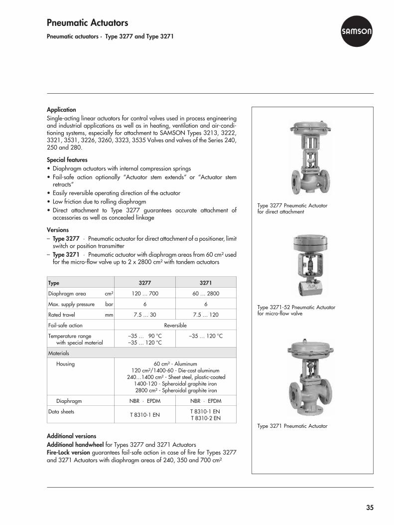
Pneumatic ActuatorsPneumatic actuators · Type 3277 and Type 3271
ApplicationSingle-acting linear actuators for control valves used in process engineeringand industrial applications as well as in heating, ventilation and air-condi-tioning systems, especially for attachment to SAMSON Types 3213, 3222,3321, 3531, 3226, 3260, 3323, 3535 Valves and valves of the Series 240,250 and 280.
Special features• Diaphragm actuators with internal compression springs• Fail-safe action optionally “Actuator stem extends“ or “Actuator stem
retracts“• Easily reversible operating direction of the actuator• Low friction due to rolling diaphragm• Direct attachment to Type 3277 guarantees accurate attachment of
accessories as well as concealed linkage
Versions– Type 3277 · Pneumatic actuator for direct attachment of a positioner, limit
switch or position transmitter– Type 3271 · Pneumatic actuator with diaphragm areas from 60 cm² used
for the micro-flow valve up to 2 x 2800 cm² with tandem actuators
Type 3277 3271
Diaphragm area cm² 120 … 700 60 … 2800
Max. supply pressure bar 6 6
Rated travel mm 7.5 … 30 7.5 … 120
Fail-safe action Reversible
Temperature rangewith special material
–35 … 90 °C–35 … 120 °C
–35 … 120 °C
Materials
Housing 60 cm² - Aluminum120 cm²/1400-60 - Die-cast aluminum
240…1400 cm² - Sheet steel, plastic-coated1400-120 - Spheroidal graphite iron2800 cm² - Spheroidal graphite iron
Diaphragm NBR · EPDM NBR · EPDM
Data sheets T 8310-1 EN T 8310-1 ENT 8310-2 EN
Additional versionsAdditional handwheel for Types 3277 and 3271 ActuatorsFire-Lock version guarantees fail-safe action in case of fire for Types 3277and 3271 Actuators with diaphragm areas of 240, 350 and 700 cm²
Type 3277 Pneumatic Actuatorfor direct attachment
Type 3271-52 Pneumatic Actuatorfor micro-flow valve
Type 3271 Pneumatic Actuator
35
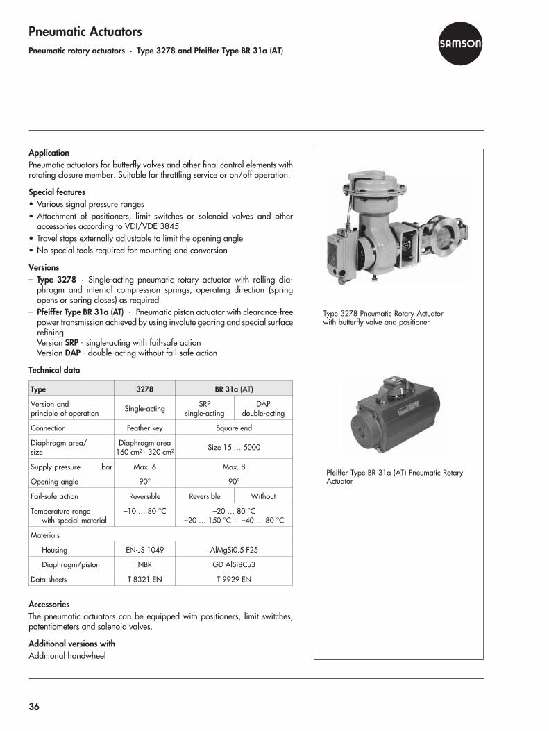
Pneumatic ActuatorsPneumatic rotary actuators · Type 3278 and Pfeiffer Type BR 31a (AT)
ApplicationPneumatic actuators for butterfly valves and other final control elements withrotating closure member. Suitable for throttling service or on/off operation.
Special features• Various signal pressure ranges• Attachment of positioners, limit switches or solenoid valves and other
accessories according to VDI/VDE 3845• Travel stops externally adjustable to limit the opening angle• No special tools required for mounting and conversion
Versions– Type 3278 · Single-acting pneumatic rotary actuator with rolling dia-
phragm and internal compression springs, operating direction (springopens or spring closes) as required
– Pfeiffer Type BR 31a (AT) · Pneumatic piston actuator with clearance-freepower transmission achieved by using involute gearing and special surfacerefiningVersion SRP - single-acting with fail-safe actionVersion DAP - double-acting without fail-safe action
Technical data
Type 3278 BR 31a (AT)
Version andprinciple of operation Single-acting SRP
single-actingDAP
double-acting
Connection Feather key Square end
Diaphragm area/size
Diaphragm area160 cm² · 320 cm² Size 15 … 5000
Supply pressure bar Max. 6 Max. 8
Opening angle 90° 90°
Fail-safe action Reversible Reversible Without
Temperature rangewith special material
–10 … 80 °C –20 … 80 °C–20 … 150 °C · –40 … 80 °C
Materials
Housing EN-JS 1049 AlMgSi0.5 F25
Diaphragm/piston NBR GD AlSi8Cu3
Data sheets T 8321 EN T 9929 EN
AccessoriesThe pneumatic actuators can be equipped with positioners, limit switches,potentiometers and solenoid valves.
Additional versions withAdditional handwheel
Type 3278 Pneumatic Rotary Actuatorwith butterfly valve and positioner
Pfeiffer Type BR 31a (AT) Pneumatic RotaryActuator
36

Electric ActuatorsElectric actuators · Types 5824, 5825, 5857 and 3374
Electrohydraulic actuator · Type 3274
ApplicationElectric actuators for control valves used in heating, ventilation and air-condi-tioning systems as well as in process engineering and industrial energy trans-fer networks
Versions– Type 5824 · Electric actuator with additional handwheel– Type 5825 · Electric actuator with fail-safe action “Actuator stem ex-
tends“ or “Actuator stem retracts“– Type 5857 · Electric Actuator– Type 3374 · Electric actuator optionally with fail-safe action, integrated
yoke or centrally attached using a coupling nut– Type 3274 · Electrohydraulic actuator, version with electric override op-
tionally with fail-safe action
Technical data
Type 5824 5825 5857 3374 3274
Rated travel mm 6 · 12 · 15 6 15 · 30 15 · 30
Actuator force,max. N 700 280/
500 300 2500 7700
Fail-safe action – • – • •
Override • – • • •
Power supply 230, 24 V/50 Hz120 V/60 Hz
230 V,24 V/50 Hz
230, 24 V/50 Hz,120,
24 V/60 Hz
230, 110,24 V
50/60 Hz
Permissible ambienttemperature 0 … 50 °C 5…
60 °C–10…60 °C
Additional electrical equipment
Electric positioner Digital Digital Digital Analog
Operation withTROVIS-VIEW • • • –
Limit switch 2 – 2 Max. 3
Potentiometer 1 – 2 Max. 2
Data sheets T 5824 EN T 5857 EN T 8331 EN T 8340 EN
Additional versionsType 5825, Type 3274 and Type 3374 with fail-safe action “Actuator stemextends“ used in combination with different SAMSON valves are typetestedaccording to DIN 14597 by the German Technical Inspectorate TÜV.
Type 5824/5825 Electric Actuator
Type 5857 Electric Actuator
Type 3374 Electrohydraulic Actuator
Type 3274 Electrohydraulic Actuator
37
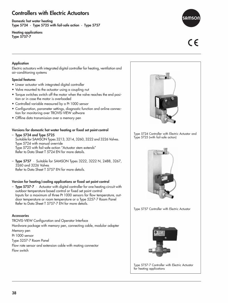
Controllers with Electric ActuatorsDomestic hot water heatingType 5724 · Type 5725 with fail-safe action · Type 5757
Heating applicationsType 5757-7
ApplicationElectric actuators with integrated digital controller for heating, ventilation andair-conditioning systems
Special features• Linear actuator with integrated digital controller• Valve mounted to the actuator using a coupling nut• Torque switches switch off the motor when the valve reaches the end posi-
tion or in case the motor is overloaded• Controlled variable measured by a Pt 1000 sensor• Configuration, parameter settings, diagnostic function and online connec-
tion for monitoring over TROVIS-VIEW software• Offline data transmission over a memory pen
Versions for domestic hot water heating or fixed set point control– Type 5724 and Type 5725
Suitable for SAMSON Types 3213, 3214, 3260, 3222 and 3226 Valves.Type 5724 with manual overrideType 5725 with fail-safe action “Actuator stem extends”Refer to Data Sheet T 5724 EN for more details.
– Type 5757 · Suitable for SAMSON Types 3222, 3222 N, 2488, 3267,3260 and 3226 ValvesRefer to Data Sheet T 5757 EN for more details.
Version for heating/cooling applications or fixed set point control– Type 5757-7 · Actuator with digital controller for one heating circuit with
outdoor-temperature-based control or fixed set point controlInputs for a maximum of three Pt 1000 sensors for flow temperature, out-door temperature or room temperature or a Type 5257-7 Room PanelRefer to Data Sheet T 5757-7 EN for more details.
AccessoriesTROVIS-VIEW Configuration and Operator InterfaceHardware package with memory pen, connecting cable, modular adapterMemory penPt 1000 sensorType 5257-7 Room PanelFlow rate sensor and extension cable with mating connectorFlow switch
Type 5724 Controller with Electric Actuator andType 5725 (with fail-safe action)
Type 5757 Controller with Electric Actuator
Type 5757-7 Controller with Electric Actuatorfor heating applications
38

Pneumatic and Electropneumatic PositionersPositioners · Type 3760, Types 4765/4763 and Types 3766/3767
EEx d positioner with Type 6116 i/p Converter
ApplicationPositioners for attachment to pneumatic control valves
Versions– Type 3760 · Positioner for direct attachment to Type 3277 Actuator– Type 4765/4763 · Positioner for attachment according to IEC 60534– Type 3766/3767 · Single- or double-acting positioners for direct attach-
ment to Type 3277 Actuators as well as for attachment according toIEC 60534 or for attachment to rotary actuators according toVDI/VDE 3845
Technical data
Type 3760 4765 4763 3766 3767
Rated travel mm 5 … 15 7.5 … 90 7.5 … 120
Opening angle – – Up to 90°
Reference variable
0.2 … 1 bar • • – • –
4(0) … 20 mA • – • – •
1 … 5 mA • – • – •
Supply air Supply pressure 1.4 … 6 bar (20 … 90 psi)
Output Max Signal pressure 0 … 6 bar (0 … 90 psi)
Characteristic Linear
Permissibleambienttemperature
–20 …70 °C
–35 …80 °C
–20 …70 °C –20...80 °C
Extended temperature range down to –40 °C on request
Degree of protection IP 54 · IP 65 as special version
Explosion protection
EEx ia IIC T6 • – • • •
FM/CSA • – • • •
EEx d* • • – • –
Additional electrical equipment
Limit switch 1 inductive – – 2 inductive
Solenoid valve – – – •
Position transmitter – – – •
Data sheets T 8385 EN T 8359 EN T 8355 EN
*EEx d · Used in combination with a Type 6116 i/p Converter, the pneu-matic positioners are flameproof i/p positioners.
JIS
Type 3760 Pneumatic or ElectropneumaticPositioner
Type 4763 Electropneumatic Positioner
Type 3766 Ex d Positioner with Type 6116 i/pConverter
39
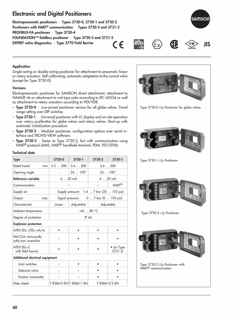
Electronic and Digital PositionersElectropneumatic positioners · Types 3730-0, 3730-1 and 3730-2Positioners with HART® communication · Types 3730-3 and 3731-3PROFIBUS-PA positioner · Type 3730-4FOUNDATION™ fieldbus positioner · Type 3730-5 and 3731-5EXPERT valve diagnostics · Type 3770 Field Barrier
ApplicationSingle-acting or double-acting positioner for attachment to pneumatic linearor rotary actuators. Self-calibrating, automatic adaptation to the control valve(except for Type 3730-0).
VersionsElectropneumatic positioner for SAMSON direct attachment, attachment toNAMUR rib or attachment to rod-type yoke according to IEC 60534 as wellas attachment to rotary actuators according to VDI/VDE.– Type 3730-0 · Low-priced positioner version for all globe valves. Travel
range setting over DIP switches– Type 3730-1 · Universal positioner with LC display and on-site operation
over rotary pushbutton for globe valves and rotary valves. Start-up withautomatic initialization procedure
– Type 3730-2 · Modular positioner, configuration options over serial in-terface and TROVIS-VIEW software
– Type 3730-3 · Same as Type 3730-2, but with communication usingHART® protocol (AMS, HART® handheld terminal, PDM, FDT/DTM)
Technical data
Type 3730-0 3730-1 3730-2 3730-3
Rated travel mm 5.3 … 200 3.6 … 200 3.6 … 200
Opening angle � 24 … 100° 24 … 100°
Reference variable 4 … 20 mA 4 … 20 mA
Communication – – HART®
Supply air Supply pressure 1.4 … 7 bar (20 … 105 psi)
Output max. Signal pressure 0 … 7 bar (0 … 105 psi)
Characteristic Linear Adjustable Adjustable
Ambient temperature –45 … 80 °C
Degree of protection IP 66
Explosion protection
ATEX EEx i/EEx nA/nL • • • •
FM/CSA intrinsicallysafe/non incendive – • • •
ATEX EEx dwith field barrier • • • • (or Type
3731-3)
Additional electrical equipment
Limit switches – • • •
Solenoid valve – – • •
Position transmitter – – • •
Data sheets T 8384-0 EN T 8384-1 EN T 8384-2/3 EN
JIS
Type 3730-0 i/p Positioner for globe valves
Type 3730-1 i/p Positioner
Type 3730-2 i/p Positioner
Type 3730-3 i/p Positioner withHART® communication
40
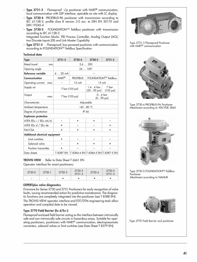
– Type 3731-3 · Flameproof i/p positioner with HART® communication,local communication with SSP interface, operable on site with LC display
– Type 3730-4 · PROFIBUS-PA positioner with transmission according toIEC 61158-2, profile class B version 3.0 acc. to DIN EN 50170 andDIN 19245-4
– Type 3730-5 · FOUNDATION™ fieldbus positioner with transmissionaccording to IEC 61158-2.Integrated function blocks: PID Process Controller, Analog Output (AO),two Discrete Inputs (DI) and Link Master Capability
– Type 3731-5 · Flameproof, bus-powered positioner with communicationaccording to FOUNDATIONTM fieldbus Specification
Technical data
Type 3731-3 3730-4 3730-5 3731-5
Rated travel mm 3,6 … 200
Opening angle 24 … 100°
Reference variable 4 … 20 mA –
Communication HART® PROFIBUS FOUNDATIONTM fieldbus
Operating current max. – 15 mA 15 mA
Supply air 7 bar (105 psi) 1.4…6 bar(20…90 psi)
7 bar(105 psi)
Output max. 7 bar (105 psi) 0…6 bar(0…90 psi)
Characteristic Adjustable
Ambient temperature –45…80 °C
Degree of protection IP 66
Explosion protection
ATEX EEx i / EEx nA/nL – • • –
ATEX EEx d / EEx de • – – •
FM/CSA • • • •
Additional electrical equipment
Limit switches • – – –
Solenoid valve – • • •
Position transmitter • – – –
Data sheets T 8387 EN T 8384-4 EN T 8384-5 EN T 8387-5 EN
TROVIS-VIEW · Refer to Data Sheet T 6661 ENOperator interface for smart positioners:
3730-0 3730-1 3730-2 3730-33731-3 3730-4 3730-5
3731-5
– – • • • •
EXPERTplus valve diagnosticsFirmware for Series 3730 and 3731 Positioners for early recognition of valvefaults, issuing recommended action for predictive maintenance. The diagnos-tic functions are completely integrated into the positioner (see T 8388 EN).The TROVIS-VIEW operator interface and FDT/DTM engineering tools allowoperation and compiled data to be viewed.
Type 3770 Field Barrier (Ex d/Ex i)Flameproof enclosed field barrier acting as the interface between intrinsicallysafe and non-intrinsically safe circuits in hazardous areas. Suitable for oper-ating positioners, positioners with HART® communication, electropneumaticconverters, solenoid valves or limit switches (see Data Sheet T 8379 EN).
Type 3731-3 Flameproof Positionerwith HART® communication
Type 3730-4 PROFIBUS-PA PositionerAttachment according to VDI/VDE 3845
Type 3730-5 FOUNDATIONTM fieldbusPositionerAttachment according to NAMUR
Type 3770 Field Barrier and positioner
41
SoftwareTROVIS-VIEW 6661
SAMSON Valve Sizing
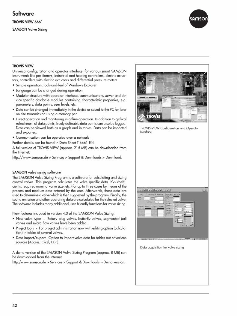
TROVIS-VIEWUniversal configuration and operator interface for various smart SAMSONinstruments like positioners, industrial and heating controllers, electric actua-tors, controllers with electric actuators and differential pressure meters.• Simple operation, look-and-feel of Windows Explorer• Language can be changed during operation• Modular structure with operator interface, communications server and de-
vice-specific database modules containing characteristic properties, e.g.parameters, data points, user levels, etc.
• Data can be changed immediately in the device or saved to the PC for lateron-site transmission using a memory pen
• Direct operation and monitoring in online operation. In addition to cyclicalrefreshment of data points, freely definable data points can also be logged.Data can be viewed both as a graph and in tables. Data can be importedand exported.
• Communication can be operated over a networkFurther details can be found in Data Sheet T 6661 EN.A full version of TROVIS-VIEW (approx. 215 MB) can be downloaded fromthe Internet:http://www.samson.de > Services > Support & Downloads > Download.
SAMSON valve sizing softwareThe SAMSON Valve Sizing Program is a software for calculating and sizingcontrol valves. This program calculates the valve-specific data (Kvs coeffi-cients, required nominal valve size, etc.) for up to three cases by means of theprocess and medium data entered by the user. Afterwards, these data areused to determine a valve which is then suggested by the program. Finally, thesound emission and other operating data are calculated for the selected valve.The software includes many additional user-friendly functions for valve sizing.
New features included in version 4.0 of the SAMSON Valve Sizing:• New valve types · Rotary plug valves, butterfly valves, segmented ball
valves and micro-flow valves have been added.• Project tools · For project administration now with editing option (calcula-
tion) in tables of several valves.• Data import/export · Option to import valve data for tables out of various
sources (Access, Excel, DBF).
A demo version of the SAMSON Valve Sizing Program (approx. 8 MB) canbe downloaded from the Internet:http:/www.samson.de > Services > Support & Downloads > Demo version.
TROVIS-VIEW Configuration and OperatorInterface
Data acquisition for valve sizing
42

Valve AccessoriesLimit switches · Type 4746, Type 3776, Type 4744 EEx d, Type 3738-20, Type 3768Position transmitter · Type 4748Solenoid valves · Type 3701 and Type 3963Pneumatic lock-up valve · Type 3709Supply pressure regulator · Type 4708Reversing amplifier · Type 3710Pneumatic volume booster · Type 3755
Limit switchesLimit switches issue an electric or pneumatic signal when an adjusted limitvalue is exceeded or not reached.
Versions– Type 4746-x2 · Inductive limit switch
Type 4746-x3 · Electric limit switchType 4746-x4 · Pneumatic limit switch
– Type 3776-0 · Inductive or electric limit switchType 3776-1 · Explosion-protected limit switch
– Type 4744/-2 · Electric limit switch EEx ed/EEx d– Type 3738-20 · Electronic limit switch for on/off rotary actuators
– Type 3768 · Inductive limit switch
Type 4746 3776 4744 3738 3768
Version -x2 -x3 -x4 -0 -1 – -2 -20 –
Travelrange
mm 7.5…150 7.5 …210 7.5...150 15 – 7.5
...120
Opening angle – max.0 … 180° – 0…
170° –
Switching element
Inductive • – – • – – – •
Electric – • • • • – –
Pneumatic – – • – – – – – –
Electronic – – – – – – – • –
Explosion protection
II 2 G EEx iaIIC T6
• • – – • EEx ed EEx d • •
FM/CSA • • – – – – – – •
Perm. ambienttemperature in °C
–20...70
–20...85
–20...60 –45...80 –55
...70–20...75
–40...80
–45...80
Data sheets T 8365 EN T 8368 EN T 8367 EN 8390 8356
EEx d · Combined with a Type 3770 Field Barrier, Type 3776 is aflameproof limit switch.
JIS
Type 4746 Limit Switch
Type 3776 Limit Switch
Type 4744 Limit Switch EEx ed (without cover)
Type 3738-20 Electronic Limit Switch
Type 3768 Inductive Limit Switch
43
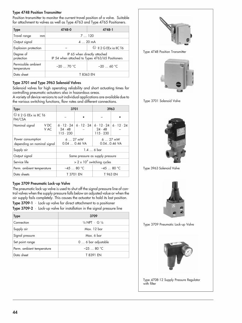
Type 4748 Position TransmitterPosition transmitter to monitor the current travel position of a valve. Suitablefor attachment to valves as well as Type 4763 and Type 4765 Positioners.
Type 4748-0 4748-1
Travel range mm 7 … 120
Output signal 4 … 20 mA
Explosion protection – II 2 G EEx ia IIC T6
Degree ofprotection
IP 65 when directly attachedIP 54 when attached to Types 4763/65 Positioners
Permissible ambienttemperature –20 … 70 °C –20 … 60 °C
Data sheet T 8363 EN
Type 3701 and Type 3963 Solenoid ValvesSolenoid valves for high operating reliability and short actuating times forcontrolling pneumatic actuators also in hazardous areas.A variety of device versions to suit individual applications are available due tothe various switching functions, flow rates and different connections.
Type 3701 3963
II 2 G EEx ia IIC T6FM/CSA
– • – •
Nominal signal V DCV AC
6 · 12 · 2424 · 48
115 · 230
6 · 12 · 24�
6 · 12 · 2424 · 48
115 · 230
6 · 12 · 24–
Power consumptiondepending on nominal signal
6 … 27 mW0.04 … 0.46 VA
6 … 27 mW0.04...0.46 VA
Supply air 1.4 … 6 bar
Output signal Same pressure as supply pressure
Service life > 2 x 10⁷ switching cycles
Perm. ambient temperature –45 … 80 °C –45 … 80 °C
Data sheets T 3701 EN T 963 EN
Type 3709 Pneumatic Lock-up ValveThe pneumatic lock-up valve is used to shut off the signal pressure line of con-trol valves when the supply pressure falls below an adjusted value or when theair supply fails completely. This causes the actuator to hold its last position.Type 3709-1 · Lock-up valve for direct attachment to a positionerType 3709-2 · Lock-up valve for installation in the signal pressure line
Type 3709
Connection ¼ NPT · G ¼
Supply air Max. 12 bar
Signal pressure Max. 6 bar
Set point range 0 … 6 bar adjustable
Perm. ambient temperature –25 … 80 °C
Data sheet T 8391 EN
Type 3963 Solenoid Valve
Type 3709 Pneumatic Lock-up Valve
Type 4708-12 Supply Pressure Regulatorwith filter
Type 3701 Solenoid Valve
Type 4748 Position Transmitter
44
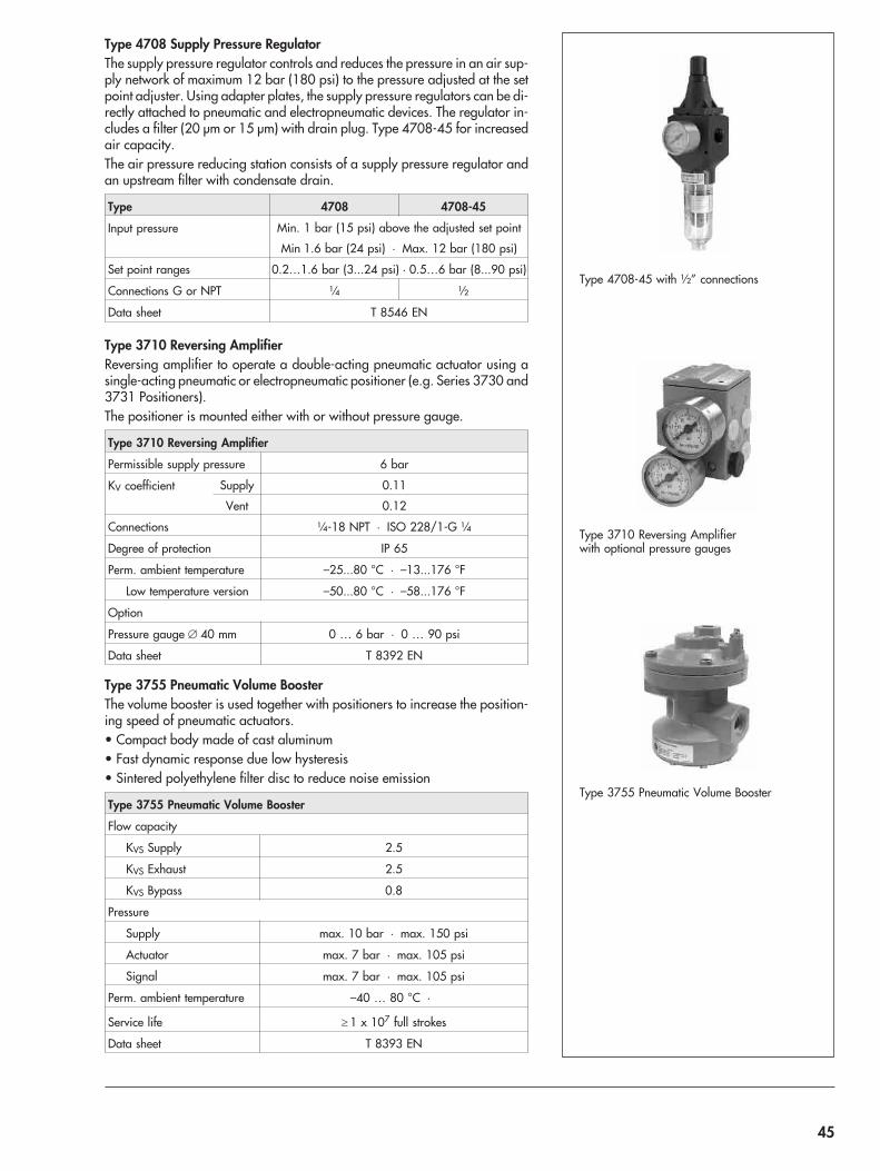
Type 4708 Supply Pressure RegulatorThe supply pressure regulator controls and reduces the pressure in an air sup-ply network of maximum 12 bar (180 psi) to the pressure adjusted at the setpoint adjuster. Using adapter plates, the supply pressure regulators can be di-rectly attached to pneumatic and electropneumatic devices. The regulator in-cludes a filter (20 µm or 15 µm) with drain plug. Type 4708-45 for increasedair capacity.The air pressure reducing station consists of a supply pressure regulator andan upstream filter with condensate drain.
Type 4708 4708-45
Input pressure Min. 1 bar (15 psi) above the adjusted set point
Min 1.6 bar (24 psi) · Max. 12 bar (180 psi)
Set point ranges 0.2…1.6 bar (3...24 psi) · 0.5…6 bar (8...90 psi)
Connections G or NPT ¼ ½
Data sheet T 8546 EN
Type 3710 Reversing AmplifierReversing amplifier to operate a double-acting pneumatic actuator using asingle-acting pneumatic or electropneumatic positioner (e.g. Series 3730 and3731 Positioners).The positioner is mounted either with or without pressure gauge.
Type 3710 Reversing Amplifier
Permissible supply pressure 6 bar
KV coefficient Supply 0.11
Vent 0.12
Connections ¼-18 NPT · ISO 228/1-G ¼
Degree of protection IP 65
Perm. ambient temperature –25...80 °C · –13...176 °F
Low temperature version –50...80 °C · –58...176 °F
Option
Pressure gauge � 40 mm 0 … 6 bar · 0 … 90 psi
Data sheet T 8392 EN
Type 3755 Pneumatic Volume BoosterThe volume booster is used together with positioners to increase the position-ing speed of pneumatic actuators.• Compact body made of cast aluminum• Fast dynamic response due low hysteresis• Sintered polyethylene filter disc to reduce noise emission
Type 3755 Pneumatic Volume Booster
Flow capacity
KVS Supply 2.5
KVS Exhaust 2.5
KVS Bypass 0.8
Pressure
Supply max. 10 bar · max. 150 psi
Actuator max. 7 bar · max. 105 psi
Signal max. 7 bar · max. 105 psi
Perm. ambient temperature –40 … 80 °C ·
Service life � 1 x 10⁷ full strokes
Data sheet T 8393 EN
Type 3710 Reversing Amplifierwith optional pressure gauges
Type 3755 Pneumatic Volume Booster
Type 4708-45 with ½” connections
45
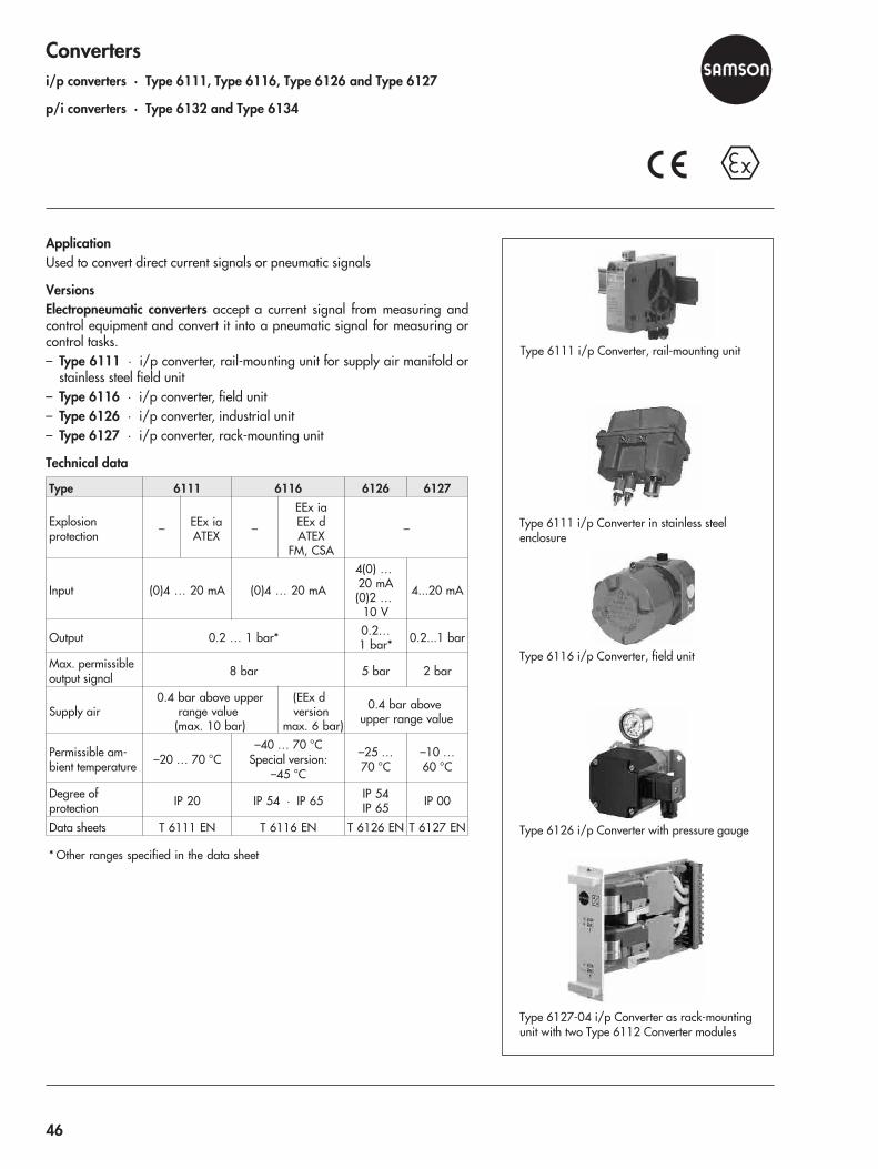
Convertersi/p converters · Type 6111, Type 6116, Type 6126 and Type 6127
p/i converters · Type 6132 and Type 6134
ApplicationUsed to convert direct current signals or pneumatic signals
VersionsElectropneumatic converters accept a current signal from measuring andcontrol equipment and convert it into a pneumatic signal for measuring orcontrol tasks.– Type 6111 · i/p converter, rail-mounting unit for supply air manifold or
stainless steel field unit– Type 6116 · i/p converter, field unit– Type 6126 · i/p converter, industrial unit– Type 6127 · i/p converter, rack-mounting unit
Technical data
Type 6111 6116 6126 6127
Explosionprotection – EEx ia
ATEX –
EEx iaEEx dATEX
FM, CSA
–
Input (0)4 … 20 mA (0)4 … 20 mA
4(0) …20 mA(0)2 …
10 V
4...20 mA
Output 0.2 … 1 bar* 0.2…1 bar* 0.2...1 bar
Max. permissibleoutput signal 8 bar 5 bar 2 bar
Supply air0.4 bar above upper
range value(max. 10 bar)
(EEx dversion
max. 6 bar)
0.4 bar aboveupper range value
Permissible am-bient temperature –20 … 70 °C
–40 … 70 °CSpecial version:
–45 °C
–25 …70 °C
–10 …60 °C
Degree ofprotection IP 20 IP 54 · IP 65 IP 54
IP 65 IP 00
Data sheets T 6111 EN T 6116 EN T 6126 EN T 6127 EN
* Other ranges specified in the data sheet
Type 6111 i/p Converter, rail-mounting unit
Type 6111 i/p Converter in stainless steelenclosure
Type 6116 i/p Converter, field unit
Type 6126 i/p Converter with pressure gauge
Type 6127-04 i/p Converter as rack-mountingunit with two Type 6112 Converter modules
46

p/i converters accept a pneumatic signal from measuring and control equip-ment and convert it into a standardized electric signal.– Type 6132 · p/i converters for four-wire connection, available as
rail-mounting unit– Type 6134 · p/i converters for two-wire connection, available as either a
rail-mounting or field unit
Technical data
Type 6132 (4-wire) 6134 (2-wire)
Explosion protection – Ex ia/Ex d –
Input 0.2 … 1 bar*
Output 4(0) ... 20 mA0(2) ... 10 V 4 … 20 mA
Auxiliary power 230, 115, 24 V AC24 V DC 24 V DC
Permissible ambienttemperature –20 … 65 °C –20 … 65 °C
Degree of protection IP 00 · IP 20 IP 54 · IP 65
Data sheets T 6132 EN T 6134 EN
* Other ranges on request
Type 6132-04 p/i Converter, rail-mounting unit
Type 6134-03 p/i Converter, field unit
Type 6134-04 p/i Converter, rail-mounting unit
47
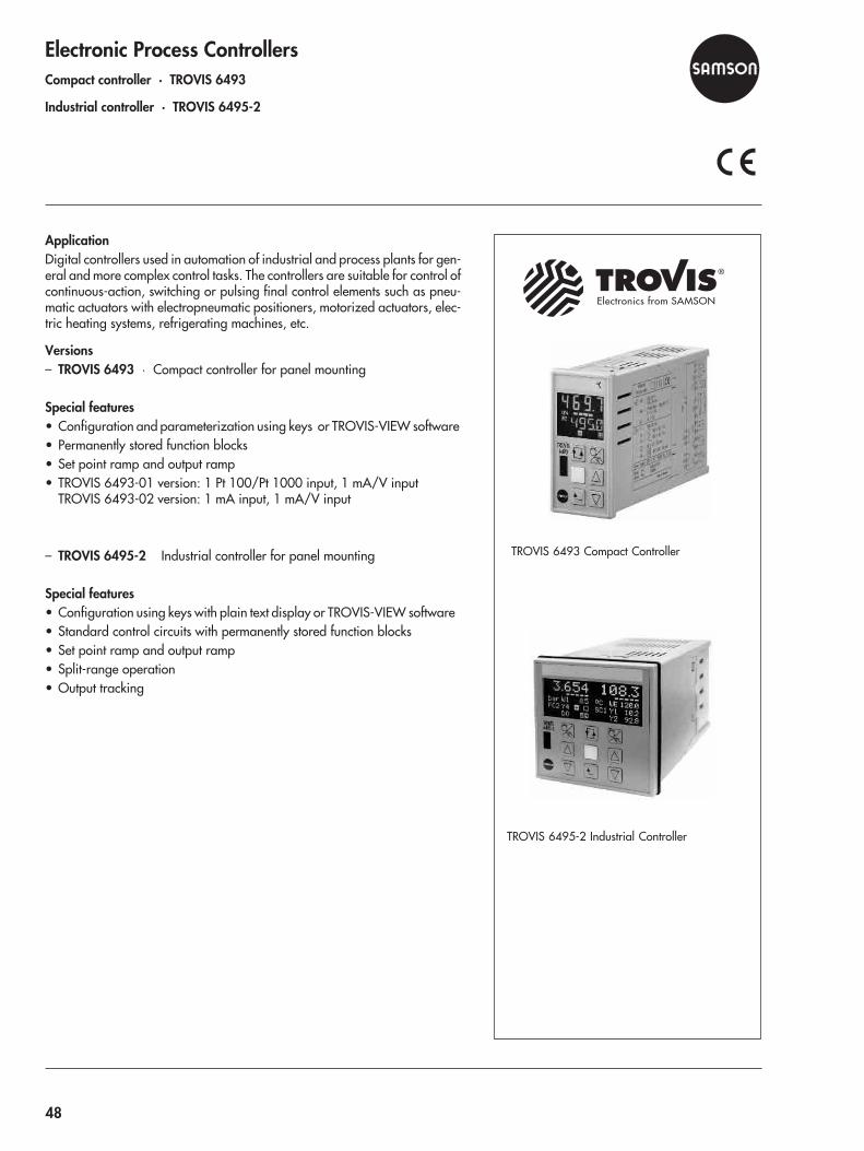
Electronic Process ControllersCompact controller · TROVIS 6493
Industrial controller · TROVIS 6495-2
ApplicationDigital controllers used in automation of industrial and process plants for gen-eral and more complex control tasks. The controllers are suitable for control ofcontinuous-action, switching or pulsing final control elements such as pneu-matic actuators with electropneumatic positioners, motorized actuators, elec-tric heating systems, refrigerating machines, etc.
Versions– TROVIS 6493 · Compact controller for panel mounting
Special features• Configuration and parameterization using keys or TROVIS-VIEW software• Permanently stored function blocks• Set point ramp and output ramp• TROVIS 6493-01 version: 1 Pt 100/Pt 1000 input, 1 mA/V input
TROVIS 6493-02 version: 1 mA input, 1 mA/V input
– TROVIS 6495-2 Industrial controller for panel mounting
Special features• Configuration using keys with plain text display or TROVIS-VIEW software• Standard control circuits with permanently stored function blocks• Set point ramp and output ramp• Split-range operation• Output tracking
®
Electronics from SAMSON
TROVIS 6495-2 Industrial Controller
TROVIS 6493 Compact Controller
48
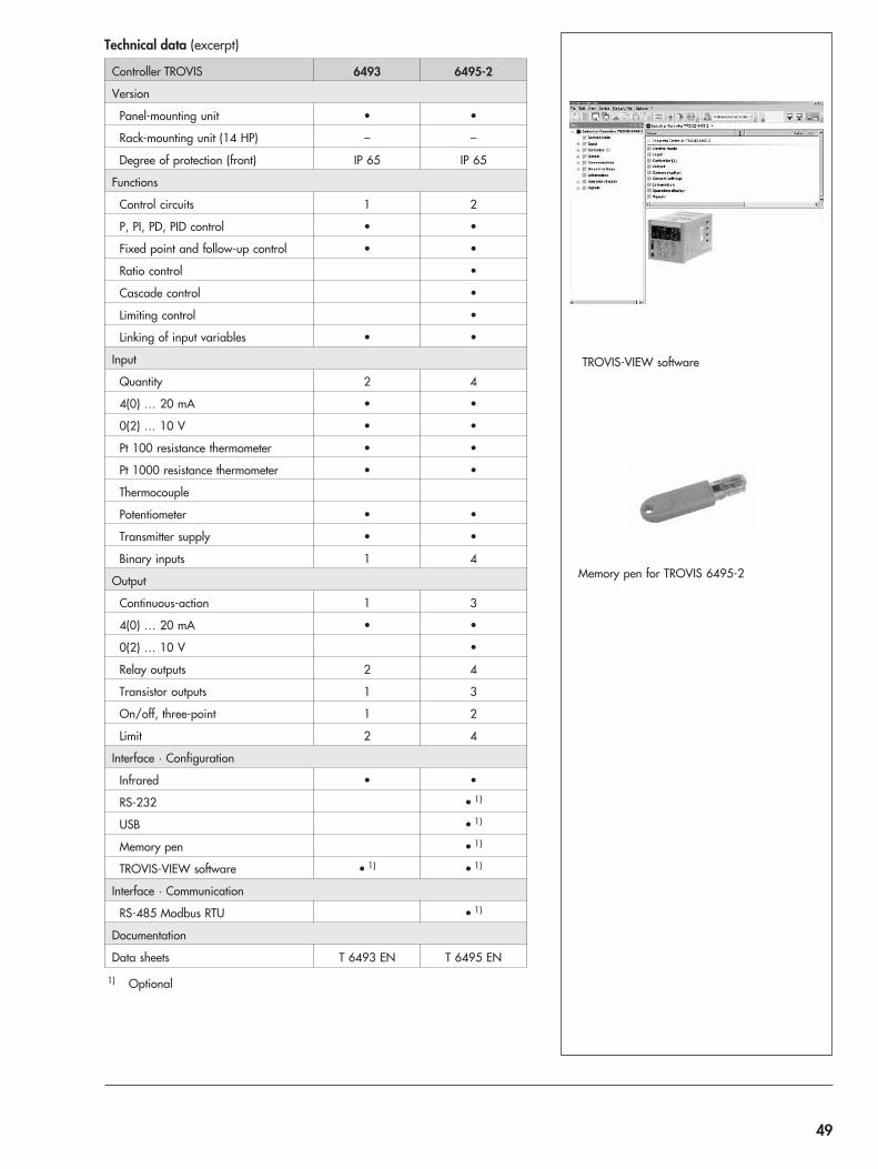
Technical data (excerpt)
Controller TROVIS 6493 6495-2
Version
Panel-mounting unit • •
Rack-mounting unit (14 HP) – –
Degree of protection (front) IP 65 IP 65
Functions
Control circuits 1 2
P, PI, PD, PID control • •
Fixed point and follow-up control • •
Ratio control •
Cascade control •
Limiting control •
Linking of input variables • •
Input
Quantity 2 4
4(0) … 20 mA • •
0(2) … 10 V • •
Pt 100 resistance thermometer • •
Pt 1000 resistance thermometer • •
Thermocouple
Potentiometer • •
Transmitter supply • •
Binary inputs 1 4
Output
Continuous-action 1 3
4(0) … 20 mA • •
0(2) … 10 V •
Relay outputs 2 4
Transistor outputs 1 3
On/off, three-point 1 2
Limit 2 4
Interface · Configuration
Infrared • •
RS-232 • 1)
USB • 1)
Memory pen • 1)
TROVIS-VIEW software • 1) • 1)
Interface · Communication
RS-485 Modbus RTU • 1)
Documentation
Data sheets T 6493 EN T 6495 EN
1) Optional
TROVIS-VIEW software
Memory pen for TROVIS 6495-2
49

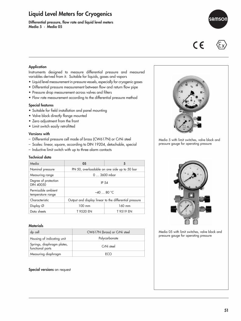
Liquid Level Meters for CryogenicsDifferential pressure, flow rate and liquid level metersMedia 5 · Media 05
ApplicationInstruments designed to measure differential pressure and measuredvariables derived from it. Suitable for liquids, gases and vapors• Liquid level measurement in pressure vessels, especially for cryogenic gases• Differential pressure measurement between flow and return flow pipe• Pressure drop measurement across valves and filters• Flow rate measurement according to the differential pressure method
Special features• Suitable for field installation and panel mounting• Valve block directly flange mounted• Zero adjustment from the front• Limit switch easily retrofitted
Versions with– Differential pressure cell made of brass (CW617N) or CrNi steel– Scales: linear, square, according to DIN 19204, detachable, special– Inductive limit switch with up to three alarm contacts
Technical data
Media 05 5
Nominal pressure PN 50, overloadable on one side up to 50 bar
Measuring range 0 … 3600 mbar
Degree of protectionDIN 40050 IP 54
Permissible ambienttemperature range –40 … 80 °C
Characteristic Output and display linear to the differential pressure
Display Ø 100 mm 160 mm
Data sheets T 9520 EN T 9519 EN
Materials
dp cell CW617N (brass) or CrNi steel
Housing of indicating unit Polycarbonate
Springs, diaphragm plates,functional parts CrNi steel
Measuring diaphragm ECO
Special versions on request
Media 5 with limit switches, valve block andpressure gauge for operating pressure
Media 05 with limit switches, valve block andpressure gauge for operating pressure
51
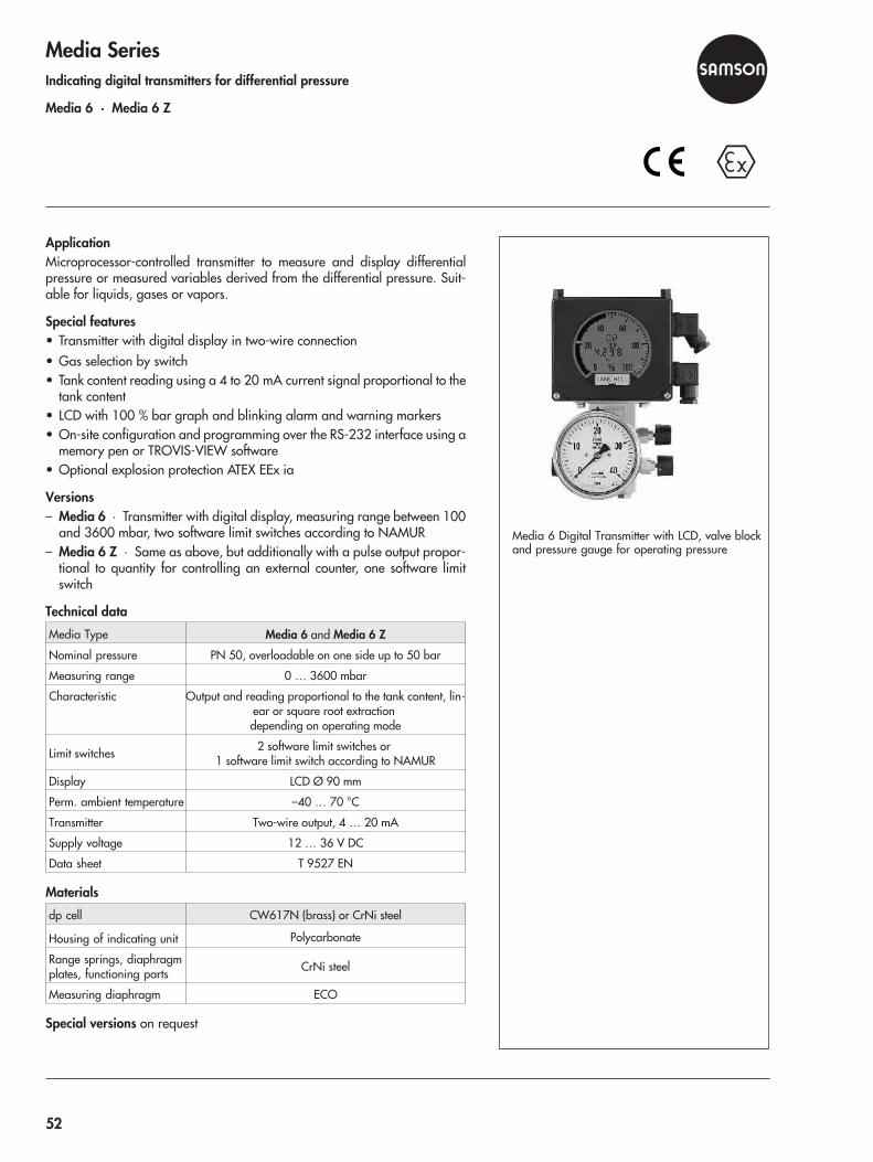
Media SeriesIndicating digital transmitters for differential pressure
Media 6 · Media 6 Z
ApplicationMicroprocessor-controlled transmitter to measure and display differentialpressure or measured variables derived from the differential pressure. Suit-able for liquids, gases or vapors.
Special features• Transmitter with digital display in two-wire connection• Gas selection by switch• Tank content reading using a 4 to 20 mA current signal proportional to the
tank content• LCD with 100 % bar graph and blinking alarm and warning markers• On-site configuration and programming over the RS-232 interface using a
memory pen or TROVIS-VIEW software• Optional explosion protection ATEX EEx ia
Versions– Media 6 · Transmitter with digital display, measuring range between 100
and 3600 mbar, two software limit switches according to NAMUR– Media 6 Z · Same as above, but additionally with a pulse output propor-
tional to quantity for controlling an external counter, one software limitswitch
Technical data
Media Type Media 6 and Media 6 Z
Nominal pressure PN 50, overloadable on one side up to 50 bar
Measuring range 0 … 3600 mbar
Characteristic Output and reading proportional to the tank content, lin-ear or square root extractiondepending on operating mode
Limit switches 2 software limit switches or1 software limit switch according to NAMUR
Display LCD Ø 90 mm
Perm. ambient temperature –40 … 70 °C
Transmitter Two-wire output, 4 … 20 mA
Supply voltage 12 … 36 V DC
Data sheet T 9527 EN
Materials
dp cell CW617N (brass) or CrNi steel
Housing of indicating unit Polycarbonate
Range springs, diaphragmplates, functioning parts CrNi steel
Measuring diaphragm ECO
Special versions on request
Media 6 Digital Transmitter with LCD, valve blockand pressure gauge for operating pressure
52
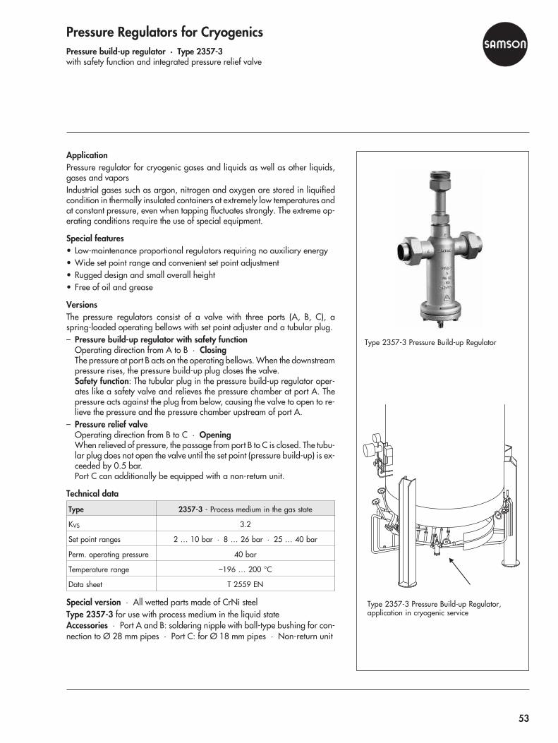
Pressure Regulators for CryogenicsPressure build-up regulator · Type 2357-3with safety function and integrated pressure relief valve
ApplicationPressure regulator for cryogenic gases and liquids as well as other liquids,gases and vaporsIndustrial gases such as argon, nitrogen and oxygen are stored in liquifiedcondition in thermally insulated containers at extremely low temperatures andat constant pressure, even when tapping fluctuates strongly. The extreme op-erating conditions require the use of special equipment.
Special features• Low-maintenance proportional regulators requiring no auxiliary energy• Wide set point range and convenient set point adjustment• Rugged design and small overall height• Free of oil and grease
VersionsThe pressure regulators consist of a valve with three ports (A, B, C), aspring-loaded operating bellows with set point adjuster and a tubular plug.– Pressure build-up regulator with safety function
Operating direction from A to B · ClosingThe pressure at port B acts on the operating bellows. When the downstreampressure rises, the pressure build-up plug closes the valve.Safety function: The tubular plug in the pressure build-up regulator oper-ates like a safety valve and relieves the pressure chamber at port A. Thepressure acts against the plug from below, causing the valve to open to re-lieve the pressure and the pressure chamber upstream of port A.
– Pressure relief valveOperating direction from B to C · OpeningWhen relieved of pressure, the passage from port B to C is closed. The tubu-lar plug does not open the valve until the set point (pressure build-up) is ex-ceeded by 0.5 bar.Port C can additionally be equipped with a non-return unit.
Technical data
Type 2357-3 - Process medium in the gas state
KVS 3.2
Set point ranges 2 … 10 bar · 8 … 26 bar · 25 … 40 bar
Perm. operating pressure 40 bar
Temperature range –196 … 200 °C
Data sheet T 2559 EN
Special version · All wetted parts made of CrNi steelType 2357-3 for use with process medium in the liquid stateAccessories · Port A and B: soldering nipple with ball-type bushing for con-nection to Ø 28 mm pipes · Port C: for Ø 18 mm pipes · Non-return unit
Type 2357-3 Pressure Build-up Regulator
Type 2357-3 Pressure Build-up Regulator,application in cryogenic service
53
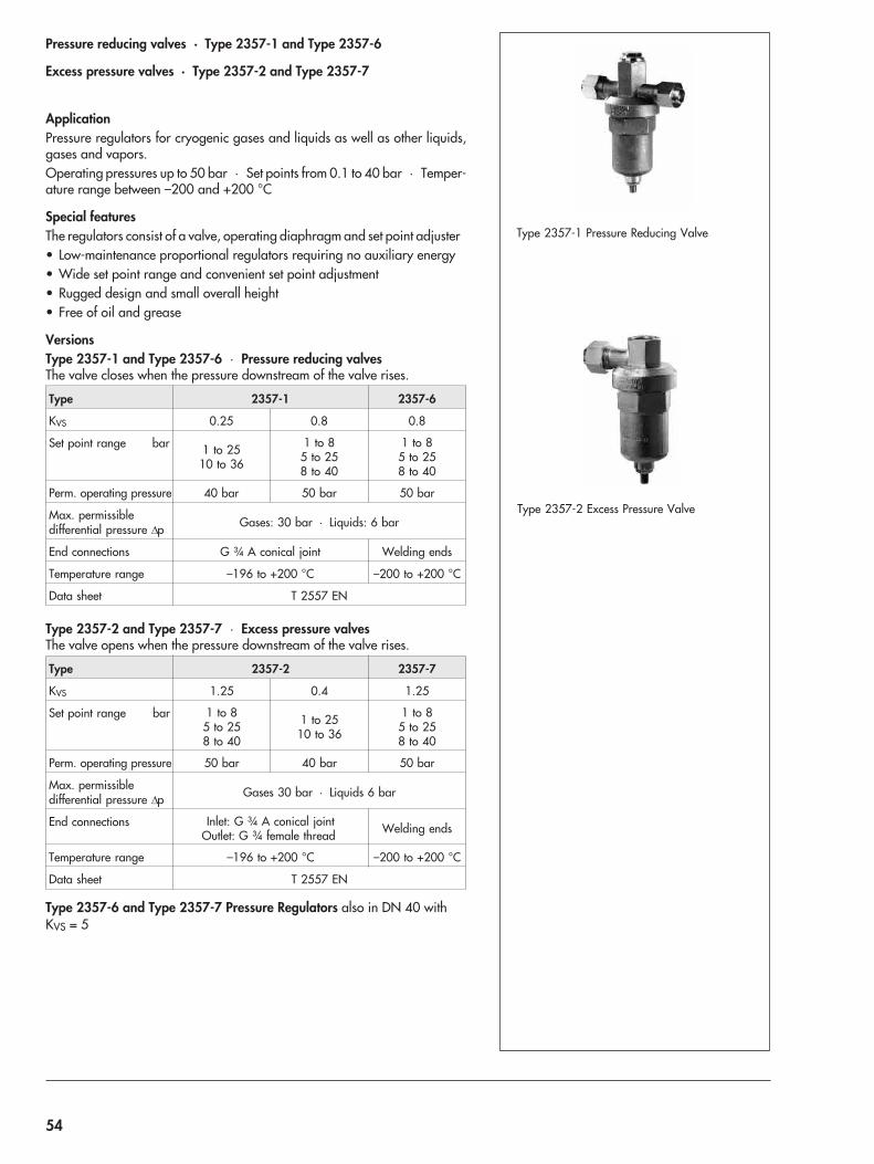
Pressure reducing valves · Type 2357-1 and Type 2357-6
Excess pressure valves · Type 2357-2 and Type 2357-7
ApplicationPressure regulators for cryogenic gases and liquids as well as other liquids,gases and vapors.Operating pressures up to 50 bar · Set points from 0.1 to 40 bar · Temper-ature range between –200 and +200 °C
Special featuresThe regulators consist of a valve, operating diaphragm and set point adjuster• Low-maintenance proportional regulators requiring no auxiliary energy• Wide set point range and convenient set point adjustment• Rugged design and small overall height• Free of oil and grease
VersionsType 2357-1 and Type 2357-6 · Pressure reducing valvesThe valve closes when the pressure downstream of the valve rises.
Type 2357-1 2357-6
KVS 0.25 0.8 0.8
Set point range bar 1 to 2510 to 36
1 to 85 to 258 to 40
1 to 85 to 258 to 40
Perm. operating pressure 40 bar 50 bar 50 bar
Max. permissibledifferential pressure �p Gases: 30 bar · Liquids: 6 bar
End connections G ¾ A conical joint Welding ends
Temperature range –196 to +200 °C –200 to +200 °C
Data sheet T 2557 EN
Type 2357-2 and Type 2357-7 · Excess pressure valvesThe valve opens when the pressure downstream of the valve rises.
Type 2357-2 2357-7
KVS 1.25 0.4 1.25
Set point range bar 1 to 85 to 258 to 40
1 to 2510 to 36
1 to 85 to 258 to 40
Perm. operating pressure 50 bar 40 bar 50 bar
Max. permissibledifferential pressure �p Gases 30 bar · Liquids 6 bar
End connections Inlet: G ¾ A conical jointOutlet: G ¾ female thread Welding ends
Temperature range –196 to +200 °C –200 to +200 °C
Data sheet T 2557 EN
Type 2357-6 and Type 2357-7 Pressure Regulators also in DN 40 withKVS = 5
Type 2357-1 Pressure Reducing Valve
Type 2357-2 Excess Pressure Valve
54
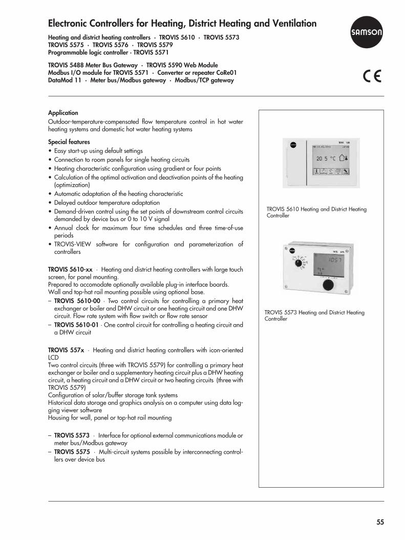
Electronic Controllers for Heating, District Heating and VentilationHeating and district heating controllers · TROVIS 5610 · TROVIS 5573TROVIS 5575 · TROVIS 5576 · TROVIS 5579Programmable logic controller · TROVIS 5571
TROVIS 5488 Meter Bus Gateway · TROVIS 5590 Web ModuleModbus I/O module for TROVIS 5571 · Converter or repeater CoRe01DataMod 11 · Meter bus/Modbus gateway · Modbus/TCP gateway
ApplicationOutdoor-temperature-compensated flow temperature control in hot waterheating systems and domestic hot water heating systems
Special features• Easy start-up using default settings• Connection to room panels for single heating circuits• Heating characteristic configuration using gradient or four points• Calculation of the optimal activation and deactivation points of the heating
(optimization)• Automatic adaptation of the heating characteristic• Delayed outdoor temperature adaptation• Demand-driven control using the set points of downstream control circuits
demanded by device bus or 0 to 10 V signal• Annual clock for maximum four time schedules and three time-of-use
periods• TROVIS-VIEW software for configuration and parameterization of
controllers
TROVIS 5610-xx · Heating and district heating controllers with large touchscreen, for panel mounting.Prepared to accomodate optionally available plug-in interface boards.Wall and top-hat rail mounting possible using optional base.– TROVIS 5610-00 · Two control circuits for controlling a primary heat
exchanger or boiler and DHW circuit or one heating circuit and one DHWcircuit. Flow rate system with flow switch or flow rate sensor
– TROVIS 5610-01 · One control circuit for controlling a heating circuit anda DHW circuit
TROVIS 557x · Heating and district heating controllers with icon-orientedLCDTwo control circuits (three with TROVIS 5579) for controlling a primary heatexchanger or boiler and a supplementary heating circuit plus a DHW heatingcircuit, a heating circuit and a DHW circuit or two heating circuits (three withTROVIS 5579)Configuration of solar/buffer storage tank systemsHistorical data storage and graphics analysis on a computer using data log-ging viewer softwareHousing for wall, panel or top-hat rail mounting
– TROVIS 5573 · Interface for optional external communications module ormeter bus/Modbus gateway
– TROVIS 5575 · Multi-circuit systems possible by interconnecting control-lers over device bus
TROVIS 5573 Heating and District HeatingController
TROVIS 5610 Heating and District HeatingController
55

– TROVIS 5576 · Multi-circuit systems possible by interconnecting control-lers over device busModbus interface RS-232 for modem operation or for connection to cableconverter RS-232/RS-485 for bus operationAlarm notification via text message (modem required)Prepared for meter bus plug-in module for communication with a maximumof six heat meters
– TROVIS 5579 · Three control circuits for controlling a primary heatexchanger or boiler and two supplementary heating circuits plus DHWheating, two heating circuits and one DHW circuit or three heating circuitsMulti-circuit systems possible by interconnecting controllers over device busModbus interface RS-232 for modem operation or for connection to cableconverter RS-232/RS-485 for bus operationAlarm notification via text message (modem required)Prepared for meter bus plug-in module for communication with a maximumof six heat meters
Programmable logic controller– TROVIS 5571 · Freely programmable HVAC plants and applications.
Modbus and meter bus interface• Freely programmable according to IEC 61131 using IsaGRAF®
• Illuminated display with plain text• Convenient input• 17 universal inputs individually configurable• Modbus communication over Modbus master and slave function• Alarm notification via text message or fax• Other inputs and outputs available by connecting an expansion module• Default applications
- WTF71 · Heat exchanger sequence control- Luft71 · Ventilation- KES71 · Boiler sequence control
Technical data (excerpt)
TROVIS 5575 Heating and District HeatingController
TROVIS 5576 Heating and District HeatingController
TROVIS 5579 Heating and District HeatingController
TROVIS5610
5573 5575 5576 5579 5571-01 -00
Control circuits max. 1 2 2 2 2 3 Free 1)
Heating max. 1 1 2 2 2 3 Free 1)
DHW heating max. 1 1 1 1 1 1 Free 1)
Inputs
Sensors 5 8 8 8 15 17 17
alternativelybinary • • 1 1 14 14 •
alternatively0 … 10 V0(4) … 20 mA
– – – 1 1 and14 x4 …
20 mA
1 and15 x4 …
20 mA
•
additionally binary – – 2 2 – – –
additionally0...10 V – 2 1 – – – –
Useablesensor types Pt 1000 Pt
1000Pt 100/500/1000Ni 1000, PTC, NTC
56
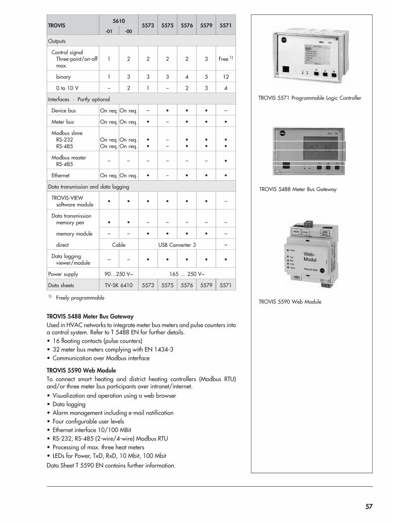
TROVIS 5488 Meter Bus GatewayUsed in HVAC networks to integrate meter bus meters and pulse counters intoa control system. Refer to T 5488 EN for further details.• 16 floating contacts (pulse counters)• 32 meter bus meters complying with EN 1434-3• Communication over Modbus interface
TROVIS 5590 Web ModuleTo connect smart heating and district heating controllers (Modbus RTU)and/or three meter bus participants over intranet/internet.• Visualization and operation using a web browser• Data logging• Alarm management including e-mail notification• Four configurable user levels• Ethernet interface 10/100 MBit• RS-232, RS-485 (2-wire/4-wire) Modbus RTU• Processing of max. three heat meters• LEDs for Power, TxD, RxD, 10 Mbit, 100 Mbit
Data Sheet T 5590 EN contains further information.
TROVIS 5590 Web Module
TROVIS5610
5573 5575 5576 5579 5571-01 -00
Outputs
Control signalThree-point/on-offmax.
1 2 2 2 2 3 Free 1)
binary 1 3 3 3 4 5 12
0 to 10 V – 2 1 – 2 3 4
Interfaces · Partly optional
Device bus On req. On req. – • • • –
Meter bus On req. On req. • – • • •
Modbus slaveRS-232RS-485
On req.On req.
On req.On req.
••
––
••
••
••
Modbus masterRS-485 – – – – – – •
Ethernet On req. On req. • – • • •
Data transmission and data logging
TROVIS-VIEWsoftware module • • • • • • –
Data transmissionmemory pen • • – – – – –
memory module – – • • • • –
direct Cable USB Converter 3 –
Data loggingviewer/module – – • • • • •
Power supply 90…250 V~ 165 … 250 V~
Data sheets TV-SK 6410 5573 5575 5576 5579 5571
1) Freely programmable
TROVIS 5571 Programmable Logic Controller
TROVIS 5488 Meter Bus Gateway
57

Modbus I/O module for TROVIS 5571Expansion of inputs and outputs in the TROVIS 5571 Programmable LogicController• Maximum six inputs can optionally be used as counter input, Pt 1000 or
0 to 1000 � input, 0 to 10 V input• Four binary outputs and a maximum of two 0 to 10 V outputs
CoRe01Converter (RS-232/RS-485) or repeater for RS-485 bus networks(two-wire/four-wire)• RS-485 interfaces optionally connected over RJ11/RJ45 jacks or over
plug-in screw terminals• Slide switches to select the operating mode, transmission rate, termination
and bus bias voltage• LED to monitor communication
TV-SK 6374-1 contains further information.
DataMod 11The multi-function modem is used with Modbus RTU-capable devices of theTROVIS 5500 Automation System.• Data transmission over a long distance using public telephone networks to
a computer with suitable software installed (e.g. 55Viewer)• Error messages can be sent as text messages to a mobile phone• Built-in line splitter for further Modbus-RTU-capable devices
TV-SK 6406 contains further information.
Meter bus/Modbus gatewayGateway for HVAC networks to integrate meter bus meters into a control sys-tem.• Maximum six heat, electricity or water meters according to EN 1434-3• Conversion of input data into Modbus data
TV-SK 6408-1 contains further information.
Modbus/TCP gatewayIntegration of Modbus-capable controllers, such as TROVIS 5573, 5576 and5579 Controllers as well as TROVIS 5571 PLC into Ethernet (LAN) structures• Connection to controller optionally using RS-485, TTL or RS-232 jacks• Simultaneous access of Modbus/TCP masters in LAN possible• Firmware updates of connected controllers
TV-SK 9949-1 contains further information.
Modbus I/O module for TROVIS 5571
Modbus/TCP gateway
Converter/repeater CoRe01
Multi-function modem DataMod 11
Meter bus/Modbus gateway
58
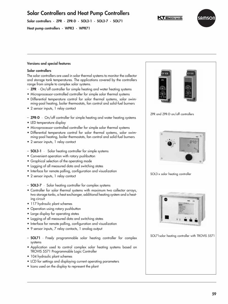
Solar Controllers and Heat Pump ControllersSolar controllers · ZPR · ZPR-D · SOL3-1 · SOL3-7 · SOL71
Heat pump controllers · WPR3 · WPR71
Versions and special features
Solar controllersThe solar controllers are used in solar thermal systems to monitor the collectorand storage tank temperatures. The applications covered by the controllersrange from simple to complex solar systems.– ZPR · On/off controller for simple heating and water heating systems• Microprocessor-controlled controller for simple solar thermal systems• Differential temperature control for solar thermal systems, solar swim-
ming-pool heating, boiler thermostats, fan control and solid-fuel burners• 2 sensor inputs, 1 relay contact
– ZPR-D · On/off controller for simple heating and water heating systems• LED temperature display• Microprocessor-controlled controller for simple solar thermal systems• Differential temperature control for solar thermal systems, solar swim-
ming-pool heating, boiler thermostats, fan control and solid-fuel burners• 2 sensor inputs, 1 relay contact
– SOL3-1 · Solar heating controller for simple systems• Convenient operation with rotary pushbutton• Graphical selection of the operating mode• Logging of all measured data and switching states• Interface for remote polling, configuration and visualization• 2 sensor inputs, 1 relay contact
– SOL3-7 · Solar heating controller for complex systems• Controller for solar thermal systems with maximum two collector arrays,
two storage tanks, a heat exchanger, additional heating system and a heat-ing circuit
• 117 hydraulic plant schemes• Operation using rotary pushbutton• Large display for operating states• Logging of all measured data and switching states• Interface for remote polling, configuration and visualization• 9 sensor inputs, 7 relay contacts, 1 analog output
– SOL71 · Freely programmable solar heating controller for complexsystems
• Application used to control complex solar heating systems based onTROVIS 5571 Programmable Logic Controller
• 104 hydraulic plant schemes• LCD for settings and displaying current operating parameters• Icons used on the display to represent the plant
ZPR and ZPR-D on/off controllers
SOL3-x solar heating controller
SOL71solar heating controller with TROVIS 5571
59

– SOL71 continued• Inputs and outputs extendable for subsequent addition of control tasks• Interfaces for communication with other field devices• 17 universal inputs, 12 binary outputs, 4 analog outputs
Heat pump controllersThe heat pump controllers are used to control heating systems with heatpumps– WPR3 · Controller for complex heat pump systems• 9 hydraulic plant schemes• Operation using rotary pushbutton• Large LCD for plant settings and information• Logging of all measured data and switching states• Interface for remote polling, configuration and visualization• 9 sensor inputs, 7 relay outputs, 1 pulse input for flow rate measurement, 1
input or output 0 to 10 V for pump speed control
– WPR71 · Freely programmable controller for complex heat pump systems• Application to control heat pump systems based on TROVIS 5571 Pro-
grammable Logic Controller• Convenient and simple plain-text operation• Various applications for hydraulic plant schemes• Inputs and outputs extendable for subsequent addition of control tasks• Data logger function and communication interfaces• Freely programmable using IsaGRAF® software• 17 universal inputs, 12 relay outputs, 2 pulse outputs for flow rate measure-
ment, 4 outputs 0 to 10 V for pump speed control
Overview (o = optional)
WPR3 heat pump controller
WPR71 heat pump controller with TROVIS 5571
ZPR
ZPR-
D
SOL3
-1
SOL3
-7
SOL7
1
WPR
3
WPR
71
On/off controller • • – – – – –
Solar heating controller – – • • • – –
Heat pump controller – – – – – • •
Operation
Rotary switch • • – – – – –
Rotary pushbutton,menu-driven – – • • – • –
Freely programmable – – – – • – •
Display
Status LEDs • • – – – – –
Temperature – • – – – – –
Plain text/graphics – – • • • • •
Inputs
Pt 1000 2 2 – 9 – 9 ––
Universal (Pt, Ni, PTC, NTC,mA, V, binary) – – 2 – 17 – 17
Pulse input – – o 1 2 1 2
0 … 10 V – – – 1 4 1 4
60
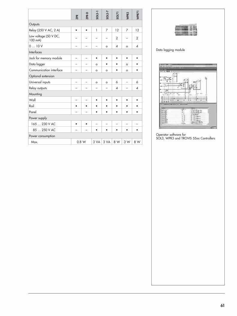
Data logging module
Operator software forSOL3, WPR3 and TROVIS 55xx Controllers
ZPR
ZPR-
D
SOL3
-1
SOL3
-7
SOL7
1
WPR
3
WPR
71
Outputs
Relay (250 V AC, 2 A) • • 1 7 12 7 12
Low voltage (50 V DC,100 mA) – – – – 2 – 2
0 … 10 V – – – o 4 o 4
Interfaces
Jack for memory module – – • • • • •
Data logger – – o • • o •
Communication interface – – o o • o •
Optional extension
Universal inputs – – o o 6 – 6
Relay outputs – – – – 4 – 4
Mounting
Wall – – • • • • •
Rail • • • • • • •
Panel – – • • • • •
Power supply
165 … 230 V AC • • – – – – –
85 … 250 V AC – – • • • • •
Power consumption
Max. 0.8 W 3 VA 3 VA 8 W 3 W 8 W
61
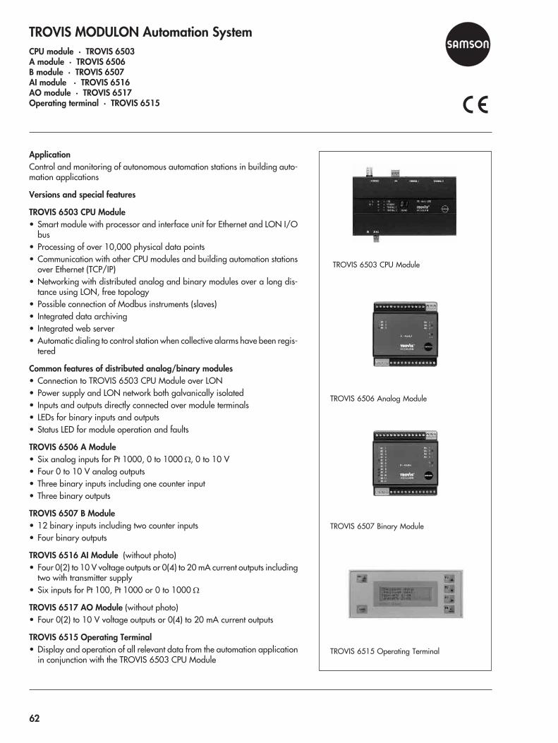
TROVIS MODULON Automation SystemCPU module · TROVIS 6503A module · TROVIS 6506B module · TROVIS 6507AI module · TROVIS 6516AO module · TROVIS 6517Operating terminal · TROVIS 6515
ApplicationControl and monitoring of autonomous automation stations in building auto-mation applications
Versions and special features
TROVIS 6503 CPU Module• Smart module with processor and interface unit for Ethernet and LON I/O
bus• Processing of over 10,000 physical data points• Communication with other CPU modules and building automation stations
over Ethernet (TCP/IP)• Networking with distributed analog and binary modules over a long dis-
tance using LON, free topology• Possible connection of Modbus instruments (slaves)• Integrated data archiving• Integrated web server• Automatic dialing to control station when collective alarms have been regis-
tered
Common features of distributed analog/binary modules• Connection to TROVIS 6503 CPU Module over LON• Power supply and LON network both galvanically isolated• Inputs and outputs directly connected over module terminals• LEDs for binary inputs and outputs• Status LED for module operation and faults
TROVIS 6506 A Module• Six analog inputs for Pt 1000, 0 to 1000 �, 0 to 10 V• Four 0 to 10 V analog outputs• Three binary inputs including one counter input• Three binary outputs
TROVIS 6507 B Module• 12 binary inputs including two counter inputs• Four binary outputs
TROVIS 6516 AI Module (without photo)• Four 0(2) to 10 V voltage outputs or 0(4) to 20 mA current outputs including
two with transmitter supply• Six inputs for Pt 100, Pt 1000 or 0 to 1000 �
TROVIS 6517 AO Module (without photo)• Four 0(2) to 10 V voltage outputs or 0(4) to 20 mA current outputs
TROVIS 6515 Operating Terminal• Display and operation of all relevant data from the automation application
in conjunction with the TROVIS 6503 CPU Module
TROVIS 6503 CPU Module
TROVIS 6506 Analog Module
TROVIS 6507 Binary Module
TROVIS 6515 Operating Terminal
62
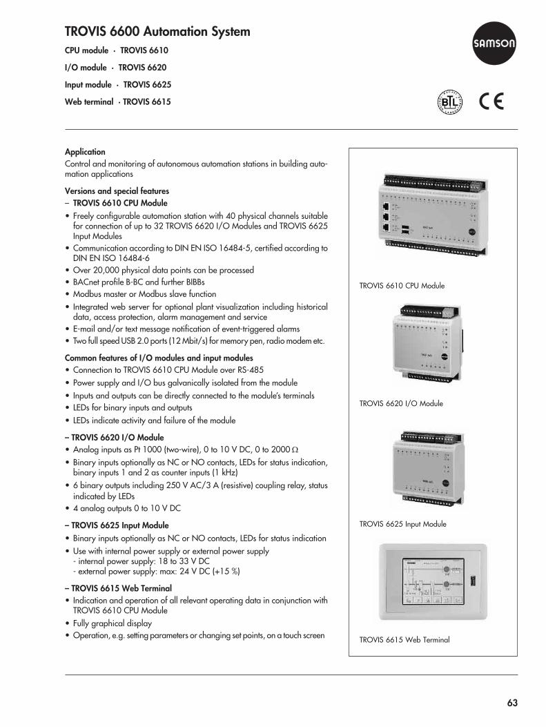
TROVIS 6600 Automation SystemCPU module · TROVIS 6610
I/O module · TROVIS 6620
Input module · TROVIS 6625
Web terminal · TROVIS 6615
ApplicationControl and monitoring of autonomous automation stations in building auto-mation applications
Versions and special features– TROVIS 6610 CPU Module• Freely configurable automation station with 40 physical channels suitable
for connection of up to 32 TROVIS 6620 I/O Modules and TROVIS 6625Input Modules
• Communication according to DIN EN ISO 16484-5, certified according toDIN EN ISO 16484-6
• Over 20,000 physical data points can be processed• BACnet profile B-BC and further BIBBs• Modbus master or Modbus slave function• Integrated web server for optional plant visualization including historical
data, access protection, alarm management and service• E-mail and/or text message notification of event-triggered alarms• Two full speed USB 2.0 ports (12 Mbit/s) for memory pen, radio modem etc.
Common features of I/O modules and input modules• Connection to TROVIS 6610 CPU Module over RS-485• Power supply and I/O bus galvanically isolated from the module• Inputs and outputs can be directly connected to the module’s terminals• LEDs for binary inputs and outputs• LEDs indicate activity and failure of the module
– TROVIS 6620 I/O Module• Analog inputs as Pt 1000 (two-wire), 0 to 10 V DC, 0 to 2000 �
• Binary inputs optionally as NC or NO contacts, LEDs for status indication,binary inputs 1 and 2 as counter inputs (1 kHz)
• 6 binary outputs including 250 V AC/3 A (resistive) coupling relay, statusindicated by LEDs
• 4 analog outputs 0 to 10 V DC
– TROVIS 6625 Input Module• Binary inputs optionally as NC or NO contacts, LEDs for status indication• Use with internal power supply or external power supply
- internal power supply: 18 to 33 V DC- external power supply: max: 24 V DC (+15 %)
– TROVIS 6615 Web Terminal• Indication and operation of all relevant operating data in conjunction with
TROVIS 6610 CPU Module• Fully graphical display• Operation, e.g. setting parameters or changing set points, on a touch screen
TROVIS 6610 CPU Module
TROVIS 6620 I/O Module
TROVIS 6625 Input Module
TROVIS 6615 Web Terminal
63
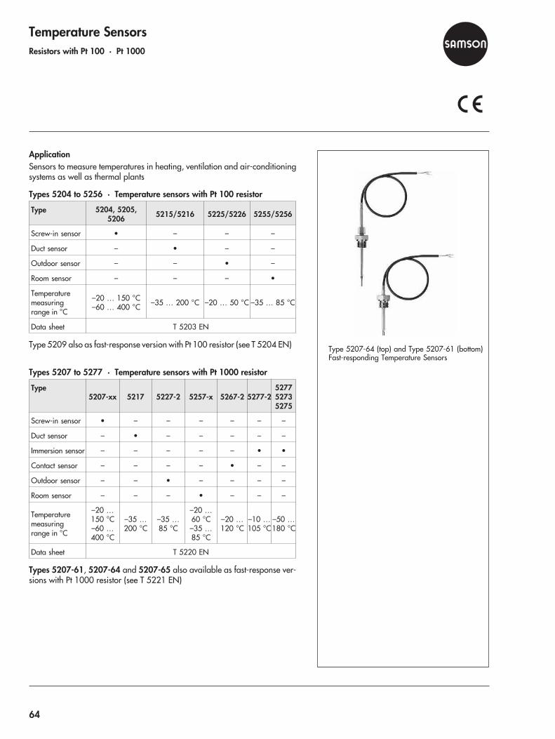
Temperature SensorsResistors with Pt 100 · Pt 1000
ApplicationSensors to measure temperatures in heating, ventilation and air-conditioningsystems as well as thermal plants
Types 5204 to 5256 · Temperature sensors with Pt 100 resistor
Type 5204, 5205,5206 5215/5216 5225/5226 5255/5256
Screw-in sensor • – – –
Duct sensor – • – –
Outdoor sensor – – • –
Room sensor – – – •
Temperaturemeasuringrange in °C
–20 … 150 °C–60 … 400 °C –35 … 200 °C –20 … 50 °C –35 … 85 °C
Data sheet T 5203 EN
Type 5209 also as fast-response version with Pt 100 resistor (see T 5204 EN)
Types 5207 to 5277 · Temperature sensors with Pt 1000 resistor
Type5207-xx 5217 5227-2 5257-x 5267-2 5277-2
527752735275
Screw-in sensor • – – – – – –
Duct sensor – • – – – – –
Immersion sensor – – – – – • •
Contact sensor – – – – • – –
Outdoor sensor – – • – – – –
Room sensor – – – • – – –
Temperaturemeasuringrange in °C
–20 …150 °C–60 …400 °C
–35 …200 °C
–35 …85 °C
–20 …60 °C–35 …85 °C
–20 …120 °C
–10 …105 °C
–50 …180 °C
Data sheet T 5220 EN
Types 5207-61, 5207-64 and 5207-65 also available as fast-response ver-sions with Pt 1000 resistor (see T 5221 EN)
Type 5207-64 (top) and Type 5207-61 (bottom)Fast-responding Temperature Sensors
64
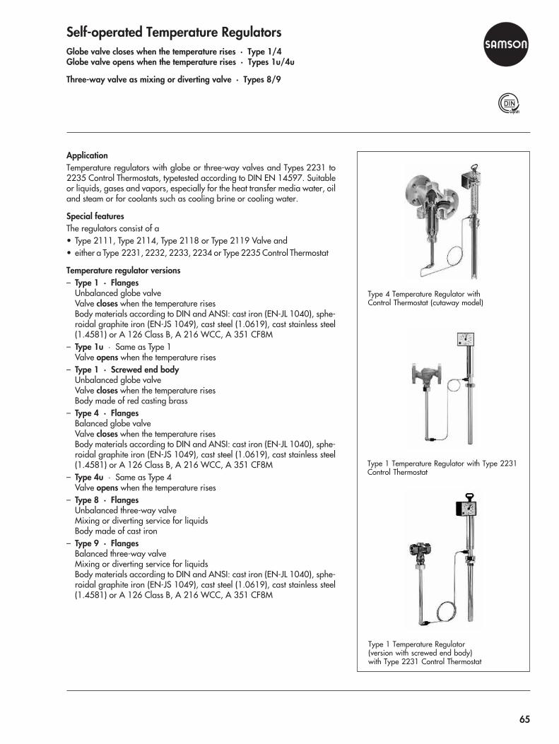
Self-operated Temperature RegulatorsGlobe valve closes when the temperature rises · Type 1/4Globe valve opens when the temperature rises · Types 1u/4u
Three-way valve as mixing or diverting valve · Types 8/9
ApplicationTemperature regulators with globe or three-way valves and Types 2231 to2235 Control Thermostats, typetested according to DIN EN 14597. Suitableor liquids, gases and vapors, especially for the heat transfer media water, oiland steam or for coolants such as cooling brine or cooling water.
Special featuresThe regulators consist of a• Type 2111, Type 2114, Type 2118 or Type 2119 Valve and• either a Type 2231, 2232, 2233, 2234 or Type 2235 Control Thermostat
Temperature regulator versions– Type 1 · Flanges
Unbalanced globe valveValve closes when the temperature risesBody materials according to DIN and ANSI: cast iron (EN-JL 1040), sphe-roidal graphite iron (EN-JS 1049), cast steel (1.0619), cast stainless steel(1.4581) or A 126 Class B, A 216 WCC, A 351 CF8M
– Type 1u · Same as Type 1Valve opens when the temperature rises
– Type 1 · Screwed end bodyUnbalanced globe valveValve closes when the temperature risesBody made of red casting brass
– Type 4 · FlangesBalanced globe valveValve closes when the temperature risesBody materials according to DIN and ANSI: cast iron (EN-JL 1040), sphe-roidal graphite iron (EN-JS 1049), cast steel (1.0619), cast stainless steel(1.4581) or A 126 Class B, A 216 WCC, A 351 CF8M
– Type 4u · Same as Type 4Valve opens when the temperature rises
– Type 8 · FlangesUnbalanced three-way valveMixing or diverting service for liquidsBody made of cast iron
– Type 9 · FlangesBalanced three-way valveMixing or diverting service for liquidsBody materials according to DIN and ANSI: cast iron (EN-JL 1040), sphe-roidal graphite iron (EN-JS 1049), cast steel (1.0619), cast stainless steel(1.4581) or A 126 Class B, A 216 WCC, A 351 CF8M
Type 1 Temperature Regulator(version with screwed end body)with Type 2231 Control Thermostat
Type 4 Temperature Regulator withControl Thermostat (cutaway model)
Type 1 Temperature Regulator with Type 2231Control Thermostat
65

Technical data · Type 2111, Type 2121 and Type 2114 Valves
Valve Type 2111, Type 2121 Type 2114
Plug Unbalanced 1) Balanced
Connection DIN DN 15… 50 G ½...1 DN 15
… 50 G ½ ...1 DN 15 … 250
ANSI NPS ½...2 – 2) NPS ½ ... 2 2) NPS ½ … 10
Nominalpressure
PN 16...40 25 25 16 … 40
Class 125 …300 250 125 … 300 125 … 300
Max. permissibletemperature
350 °C 220 °C 150 °C 350 °C
660 °F – 660 °F 660 °F
Data sheetsT … EN
21112115 2112 2113 2121
2025 2123
1) Type 2121 in DN 32, 40 and 50 as balanced valve available2) Versions with female thread also available with NPT thread
Materials
BodyDIN
EN-JL 10401.0619
Cast stainless steel(1.4581)
CC491KEN-JL 1040
1.0619Cast stainless steel
EN-JL 10401.0619
Cast stainless steel(1.4581)
ANSI A 126 Class BA 216 WCCA 351 CF8M
B 62A 126 Class B
A 216A 351 CF8M
Technical data · Type 2118 and Type 2119 Valves
Valve Type 2118 Type 2119
Plug Unbalanced Balanced for DN 32 and larger
Nominal size DN 15 … 50 DN 15 … 150 · NPS ½ ... 6
Nominalpressure PN 16 PN 16 … 40
Class 150 and 300
Max. perm.temperature 150 °C 350 °C · 660 °F
Data sheets T 2131 EN T 2133 EN · T 2134 EN
Materials
BodyDIN
ANSI
EN-JL 1040EN-JL 1040
1.06191.4581
ANSI versions on request A 216A 351 CF8M
Special versions– Valve entirely made of corrosion-resistant material– Reduced KVS coefficient– Valve with Flow Divider St I to achieve noise reduction for steam and
non-flammable gases– Valve version free of non-ferrous metals
Type 4u Temperature Regulator withType 2231 Control Thermostat
Type 8 Temperature Regulator with Type 2118Valve and Type 2232 Control Thermostat withseparate set point adjustment
Type 9 Temperature Regulator withType 2231 Control Thermostat
66

Types 2231, 2232, 2233, 2234, 2235 Control ThermostatsApplicationTemperature regulation for heating or cooling installations
Special featuresThe control thermostats consist of a temperature sensor, a set point adjusterwith temperature scale and excess temperature safety device, a capillary tubeand an operating element. They regulate the temperature of the medium bycausing the connected valve to open or close.The thermostats operate according to the liquid expansion principle.
Versions– Type 2231 · Set points from –10 °C to 150 °C (15 to 300 °F), set point
adjustment at the sensor · Suitable for liquids and steam · Installation inpipelines, vessels, heating or cooling systems
– Type 2232 · Set points from –10 °C to 250 °C (15 to 480 °F), separateset point adjustment · Application same as Type 2231
– Type 2233 · Set points from –10 °C to 150 °C (15 to 300 °F), set pointadjustment at the sensor · Suitable for liquids, air and other gases, liquidregulation with quick response times · Installation in air ducts, vessels,pipelines and other heating or cooling systems
– Type 2234 · Set points from –10 °C to 250 °C (15 to 480 °F), separateset point adjustment · Suitable for liquids, air and other gases · Applica-tion same as Type 2233
– Type 2235 · Set points from –10 °C to 250 °C (15 to 480 °F), separateset point adjustment · Capillary tube can be installed as required by theuser to measure different temperature layers · For air-heated storeroomsas well as drying, climatic and heating cabinets
Technical data · Types 2231 to 2235 Control Thermostats
Type 2231 2232 2233 2234 2235
Set point span
–10 … 90 °C, 20 … 120 °C or 50 … 150 °CFor Types 2232, 2234, 2235 also 100 … 200 °C,
150 … 250 °C
15 … 195 °F, 70 … 250 °F or 120 … 300 °FFor Types 2232, 2234, 2235 also 210 … 390 °F,
300 … 480 °F
Permissibleambient temperature
–40 … 90 °C · –40 … 175 °Fat the set point adjuster
Permissible temperatureat the sensor 100 K above the adjusted set point
Capillary tube length 3 m · 10 ft
Data sheetsT 2111 EN/T 2115 EN · T 2112 EN · T 2113 EN ·
T 2121 EN/T 2025 EN · T 2123 EN · T 2131 ENT 2133 EN/T 2134 EN
Materials
Sensor Bronze, nickel-plated Copper, nickel-plated Copper
Capillary tube Copper, nickel-plated
Special versionSensor made of CrNiMo steelCapillary tube made of CrNiMo steel or plastic-coated copperCapillary tube length: 5, 10 or 15 m (16, 33 or 50 ft)
Type 2233 Control Thermostat
Type 2232 Control Thermostat
Type 2231 Control Thermostat
67
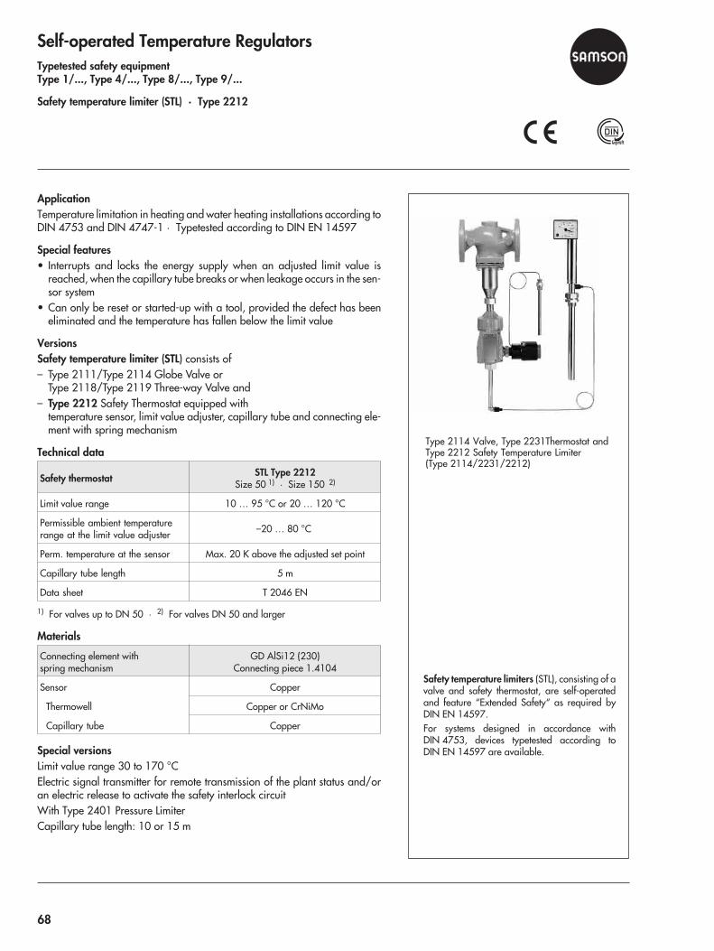
Self-operated Temperature RegulatorsTypetested safety equipmentType 1/..., Type 4/..., Type 8/..., Type 9/...
Safety temperature limiter (STL) · Type 2212
ApplicationTemperature limitation in heating and water heating installations according toDIN 4753 and DIN 4747-1 · Typetested according to DIN EN 14597
Special features• Interrupts and locks the energy supply when an adjusted limit value is
reached, when the capillary tube breaks or when leakage occurs in the sen-sor system
• Can only be reset or started-up with a tool, provided the defect has beeneliminated and the temperature has fallen below the limit value
VersionsSafety temperature limiter (STL) consists of– Type 2111/Type 2114 Globe Valve or
Type 2118/Type 2119 Three-way Valve and– Type 2212 Safety Thermostat equipped with
temperature sensor, limit value adjuster, capillary tube and connecting ele-ment with spring mechanism
Technical data
Safety thermostat STL Type 2212Size 50 1) · Size 150 2)
Limit value range 10 … 95 °C or 20 … 120 °C
Permissible ambient temperaturerange at the limit value adjuster –20 … 80 °C
Perm. temperature at the sensor Max. 20 K above the adjusted set point
Capillary tube length 5 m
Data sheet T 2046 EN
1) For valves up to DN 50 · 2) For valves DN 50 and larger
Materials
Connecting element withspring mechanism
GD AlSi12 (230)Connecting piece 1.4104
Sensor Copper
Thermowell Copper or CrNiMo
Capillary tube Copper
Special versionsLimit value range 30 to 170 °CElectric signal transmitter for remote transmission of the plant status and/oran electric release to activate the safety interlock circuitWith Type 2401 Pressure LimiterCapillary tube length: 10 or 15 m
Safety temperature limiters (STL), consisting of avalve and safety thermostat, are self-operatedand feature “Extended Safety“ as required byDIN EN 14597.For systems designed in accordance withDIN 4753, devices typetested according toDIN EN 14597 are available.
Type 2114 Valve, Type 2231Thermostat andType 2212 Safety Temperature Limiter(Type 2114/2231/2212)
68
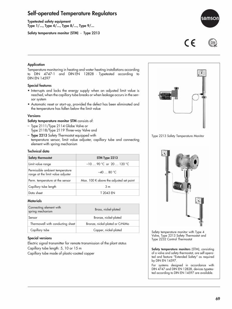
Self-operated Temperature RegulatorsTypetested safety equipmentType 1/..., Type 4/..., Type 8/..., Type 9/...
Safety temperature monitor (STM) · Type 2213
ApplicationTemperature monitoring in heating and water heating installations accordingto DIN 4747-1 and DIN EN 12828 · Typetested according toDIN EN 14597
Special features• Interrupts and locks the energy supply when an adjusted limit value is
reached, when the capillary tube breaks or when leakage occurs in the sen-sor system
• Automatic reset or start-up, provided the defect has been eliminated andthe temperature has fallen below the limit value
VersionsSafety temperature monitor STM consists of:– Type 2111/Type 2114 Globe Valve or
Type 2118/Type 2119 Three-way Valve and– Type 2213 Safety Thermostat equipped with
temperature sensor, limit value adjuster, capillary tube and connectingelement with spring mechanism
Technical data
Safety thermostat STM Type 2213
Limit value range –10 … 90 °C or 20 … 120 °C
Permissible ambient temperaturerange at the limit value adjuster –40 … 80 °C
Perm. temperature at the sensor Max. 100 K above the adjusted set point
Capillary tube length 3 m
Data sheet T 2043 EN
Materials
Connecting element withspring mechanism Brass, nickel-plated
Sensor Bronze, nickel-plated
Thermowell with conducting sheet Bronze, nickel-plated or CrNiMo
Capillary tube Copper, nickel-plated
Special versionsElectric signal transmitter for remote transmission of the plant statusCapillary tube length: 5, 10 or 15 mCapillary tube made of plastic-coated copper
Safety temperature monitors (STM), consistingof a valve and safety thermostat, are self-opera-ted and feature “Extended Safety“ as requiredby DIN EN 14597.For systems designed in accordance withDIN 4747 and DIN EN 12828, devices typetes-ted according to DIN EN 14597 are available.
Type 2213 Safety Temperature Monitor
Safety temperature monitor with Type 4Valve, Type 2213 Safety Thermostat andType 2232 Control Thermostat
69
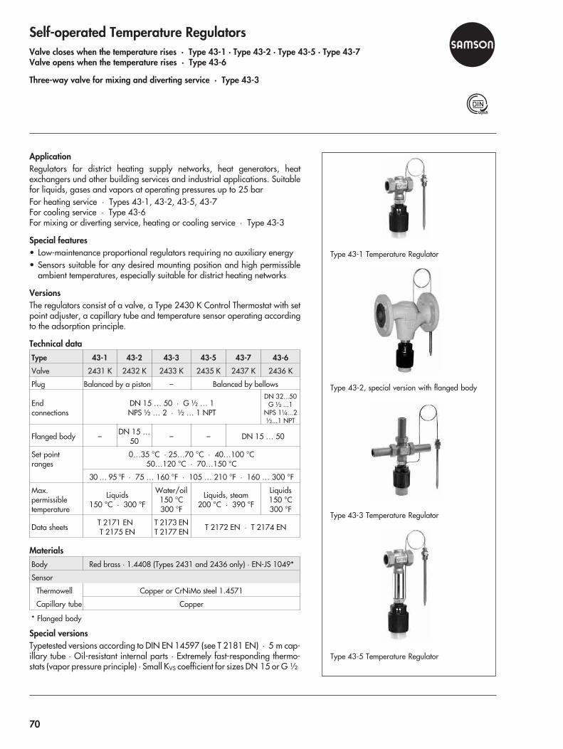
Self-operated Temperature RegulatorsValve closes when the temperature rises · Type 43-1 · Type 43-2 · Type 43-5 · Type 43-7Valve opens when the temperature rises · Type 43-6
Three-way valve for mixing and diverting service · Type 43-3
ApplicationRegulators for district heating supply networks, heat generators, heatexchangers und other building services and industrial applications. Suitablefor liquids, gases and vapors at operating pressures up to 25 barFor heating service · Types 43-1, 43-2, 43-5, 43-7For cooling service · Type 43-6For mixing or diverting service, heating or cooling service · Type 43-3
Special features• Low-maintenance proportional regulators requiring no auxiliary energy• Sensors suitable for any desired mounting position and high permissible
ambient temperatures, especially suitable for district heating networks
VersionsThe regulators consist of a valve, a Type 2430 K Control Thermostat with setpoint adjuster, a capillary tube and temperature sensor operating accordingto the adsorption principle.
Technical dataType 43-1 43-2 43-3 43-5 43-7 43-6
Valve 2431 K 2432 K 2433 K 2435 K 2437 K 2436 K
Plug Balanced by a piston – Balanced by bellows
Endconnections
DN 15 … 50 · G ½ … 1NPS ½ … 2 · ½ … 1 NPT
DN 32...50G ½ ...1
NPS 1¼...2½...1 NPT
Flanged body – DN 15 …50 – – DN 15 … 50
Set pointranges
0…35 °C · 25…70 °C · 40…100 °C50…120 °C · 70…150 °C
30 … 95 °F · 75 … 160 °F · 105 … 210 °F · 160 … 300 °F
Max.permissibletemperature
Liquids150 °C · 300 °F
Water/oil150 °C300 °F
Liquids, steam200 °C · 390 °F
Liquids150 °C300 °F
Data sheets T 2171 ENT 2175 EN
T 2173 ENT 2177 EN T 2172 EN · T 2174 EN
MaterialsBody Red brass · 1.4408 (Types 2431 and 2436 only) · EN-JS 1049*
Sensor
Thermowell Copper or CrNiMo steel 1.4571
Capillary tube Copper
* Flanged body
Special versionsTypetested versions according to DIN EN 14597 (see T 2181 EN) · 5 m cap-illary tube · Oil-resistant internal parts · Extremely fast-responding thermo-stats (vapor pressure principle) · Small KVS coefficient for sizes DN 15 or G ½
Type 43-1 Temperature Regulator
Type 43-2, special version with flanged body
Type 43-3 Temperature Regulator
Type 43-5 Temperature Regulator
70

Self-operated Temperature RegulatorsTemperature regulators with hydraulic controllers · Type 43-8 · Type 43-8 N
ApplicationTemperature regulation of instantaneous water heaters in small district heat-ing units, particularly in single or multiple-family dwellings
Special features• Low-maintenance proportional regulators requiring no auxiliary energy• Typetested according to DIN EN 14597• Regulation of small instantaneous water heaters• Idle temperature regulation• Fast-responding vapor pressure thermostats
VersionsType 43-8 and Type 43-8 N for local heat supply networks with:– Type 2430 K Thermostat with Type 2438 K Hydraulic Controller and– Type 2432 K Valve
Technical data
Valve Type 2432 K
Nominal size DN 15
KVS 2.5
Max. permissible temperature 150 °C
Control thermostat Type 2430 K (vapor pressure)
Set point range 45 … 65 °C
Max. perm. temperature at sensor 30 K above the adjusted set point
Capillary tube length 2 m
Hydraulic controller Type 2438 K
Required differential pressure 0.4 … 0.6 bar
Nominal pressure PN 16
Max. flow rate 26 l/min
Min. tapping rate 2 l/min
Data sheet T 2178 EN
Materials
Body Red brass · CW602N/CC491K/CC499K
Valve seat CW602N/Stainless steel 1.4305
Plug 1.4104 and brass resistant todezincification with EPDM soft sealing
Temperature sensorCapillary tube Copper
Sensor CrNiMo steel
Special versionWith Type 2439 K Safety Temperature Limiter
Type 43-8 Temperature Regulator withHydraulic Controller
71
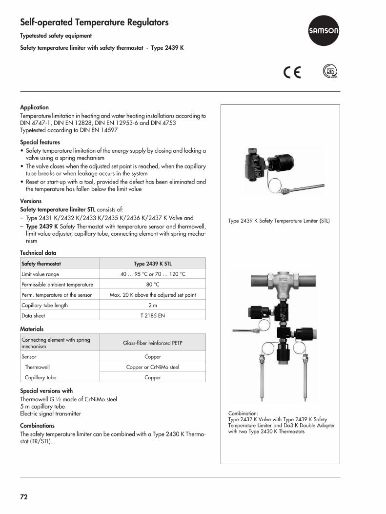
Self-operated Temperature RegulatorsTypetested safety equipment
Safety temperature limiter with safety thermostat · Type 2439 K
ApplicationTemperature limitation in heating and water heating installations according toDIN 4747-1, DIN EN 12828, DIN EN 12953-6 and DIN 4753Typetested according to DIN EN 14597
Special features• Safety temperature limitation of the energy supply by closing and locking a
valve using a spring mechanism• The valve closes when the adjusted set point is reached, when the capillary
tube breaks or when leakage occurs in the system• Reset or start-up with a tool, provided the defect has been eliminated and
the temperature has fallen below the limit value
VersionsSafety temperature limiter STL consists of:– Type 2431 K/2432 K/2433 K/2435 K/2436 K/2437 K Valve and– Type 2439 K Safety Thermostat with temperature sensor and thermowell,
limit value adjuster, capillary tube, connecting element with spring mecha-nism
Technical data
Safety thermostat Type 2439 K STL
Limit value range 40 … 95 °C or 70 … 120 °C
Permissible ambient temperature 80 °C
Perm. temperature at the sensor Max. 20 K above the adjusted set point
Capillary tube length 2 m
Data sheet T 2185 EN
Materials
Connecting element with springmechanism Glass-fiber reinforced PETP
Sensor Copper
Thermowell Copper or CrNiMo steel
Capillary tube Copper
Special versions withThermowell G ½ made of CrNiMo steel5 m capillary tubeElectric signal transmitter
CombinationsThe safety temperature limiter can be combined with a Type 2430 K Thermo-stat (TR/STL).
Type 2439 K Safety Temperature Limiter (STL)
Combination:Type 2432 K Valve with Type 2439 K SafetyTemperature Limiter and Do3 K Double Adapterwith two Type 2430 K Thermostats
72
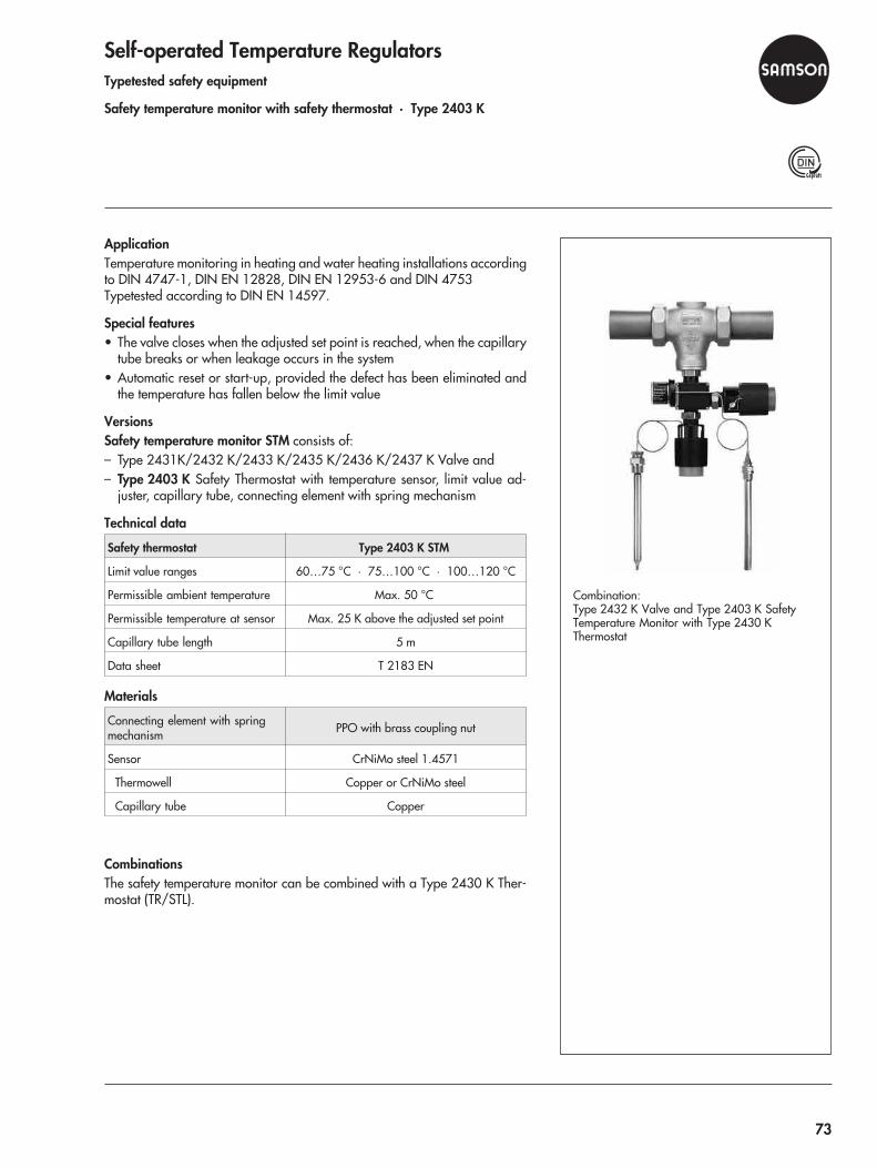
Self-operated Temperature RegulatorsTypetested safety equipment
Safety temperature monitor with safety thermostat · Type 2403 K
ApplicationTemperature monitoring in heating and water heating installations accordingto DIN 4747-1, DIN EN 12828, DIN EN 12953-6 and DIN 4753Typetested according to DIN EN 14597.
Special features• The valve closes when the adjusted set point is reached, when the capillary
tube breaks or when leakage occurs in the system• Automatic reset or start-up, provided the defect has been eliminated and
the temperature has fallen below the limit value
VersionsSafety temperature monitor STM consists of:– Type 2431K/2432 K/2433 K/2435 K/2436 K/2437 K Valve and– Type 2403 K Safety Thermostat with temperature sensor, limit value ad-
juster, capillary tube, connecting element with spring mechanism
Technical data
Safety thermostat Type 2403 K STM
Limit value ranges 60…75 °C · 75…100 °C · 100…120 °C
Permissible ambient temperature Max. 50 °C
Permissible temperature at sensor Max. 25 K above the adjusted set point
Capillary tube length 5 m
Data sheet T 2183 EN
Materials
Connecting element with springmechanism PPO with brass coupling nut
Sensor CrNiMo steel 1.4571
Thermowell Copper or CrNiMo steel
Capillary tube Copper
CombinationsThe safety temperature monitor can be combined with a Type 2430 K Ther-mostat (TR/STL).
Combination:Type 2432 K Valve and Type 2403 K SafetyTemperature Monitor with Type 2430 KThermostat
73

Self-operated Pressure RegulatorsPressure reducing valve · Type 41-23
Excess pressure valve · Type 41-73
ApplicationPressure set points from 25 mbar to 28 bar (0.35 to 405 psi) · Suitablefor liquids, gases and vapors up to 350 °C (600 °F)
Special features• Low-maintenance, medium-controlled proportional regulators requiring no
auxiliary energy• Frictionless plug stem sealed by a stainless steel bellows• Exchangeable actuator and positioning springs• Single-seated valve with upstream and downstream pressure balancing
Versions– Type 41-23 Pressure Reducing Valve · Type 2412 Valve and
Type 2413 Actuator with EPDM rolling diaphragm– Type 41-73 Excess Pressure Valve · Type 2417 Valve and
Type 2413 Actuator with EPDM rolling diaphragm
Technical data
Valve Type 2412 · Type 2417
Nominal DNsize NPS
15 … 50½ … 2
65 … 802½ and 3
1004
Max. �p 25 bar · 360 psi 20 bar · 290 psi 16 bar · 230 psi
Actuator Type 2413
Set pointranges
25 … 50 mbar · 0.05 … 0.25 bar0.1 … 0.6 bar · 0.2 … 1.2 bar · 0.8 … 2.5 bar
2 … 5 bar · 4.5 … 10 bar · 8 … 16 bar
0.35 … 0.75 psi · 0.75 … 3.5 psi1.5 … 8.5 psi · 3 … 17 psi · 10 … 35 psi
30 … 75 psi · 65 … 145 psi · 115 … 230 psi
Max. perm.temperature
Gases 350 °C (660 °F) - at the actuator max. 80 °C (175 °F)Liquids 150 °C (300 °F), with condensation chamber 350 °C (660 °F)
Steam with condensation chamber 350 °C (660 °F)
Data sheets T 2512 EN/T 2513 EN · T 2517 EN/T 2518 EN
Special versionsControl line kit for pressure tapping at the valve body (accessories)FPM rolling diaphragms for oilsFree of oil and grease for oxygen or high-purity applicationsEPDM diaphragms with PTFE facingActuator for remote set point adjustment (autoclave control)Bellows actuator for valves in DN 15 to 100, set point ranges 2 to 6 bar, 5 to10 bar, 10 to 22 bar or 20 to 28 barValve with flow divider for noise reduction with gases and vaporsVersion made entirely of corrosion-resistant materialHard-faced seat and plug · Plug with PTFE soft sealing · Wetted plastic partsFDA-compliant (max. 60 °C)
Type 41-23 Pressure Reducing Valve
Type 41-23, stainless steel version
74

Materials
Valve Type 2412 · Type 2417
Nominal pressurePN 16 PN 25 PN 40 PN 40
Class 125 Class 150 Class 300 Class 300
Max. permissibletemperature
300 °C 350 °C 350 °C 350 °C
570 °F 660 °F 660 °F 660 °F
BodyEN-JL 1040 EN-JS 1049 1.0619 1.4408
A 126 B A 216 WCC A 351 CF8M
Seat/plug CrNi steel CrNiMo steel
Actuator Type 2413
Diaphragm cases Sheet steel St 34-2 1.4301
Diaphragm EPDM with fabric insert - FPM for oilsNBR - EPDM with PTFE facing
Type 41-73 Excess Pressure Valve
75
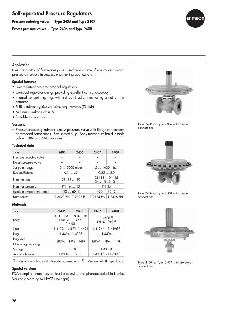
Self-operated Pressure RegulatorsPressure reducing valves · Type 2405 and Type 2407
Excess pressure valves · Type 2406 and Type 2408
ApplicationPressure control of flammable gases used as a source of energy or as com-pressed air supply in process engineering applications
Special features• Low-maintenance proportional regulators• Compact regulator design providing excellent control accuracy• Internal set point springs with set point adjustment using a nut on the
actuator• Fulfills stricter fugitive emission requirements (TA-Luft)• Minimum leakage class IV• Suitable for vacuum
Versions– Pressure reducing valve or excess pressure valve with flange connections
or threaded connections · Soft-seated plug · Body material as listed in tablebelow · DIN and ANSI versions
Technical data
Type 2405 2406 2407 2408Pressure reducing valve • – • –
Excess pressure valve – • – •
Set point range 5 … 5000 mbar 5 … 1000 mbar
KVS coefficients 0.1 … 32 0.25 … 5.0
Nominal size DN 15 … 50 DN 15 · DN 25G ½ · G ¾ · G 1
Nominal pressure PN 16 … 40 PN 25
Medium temperature range –20 … 60 °C –20 … 60 °C
Data sheets T 2520 EN T 2522 EN T 2524 EN T 2528 EN
Materials
Type 2405 2406 2407 2408
BodyEN-JL 1040 · EN-JS 1049
1.0619 · 1.45711.4408
1.4408 1)
EN-JS 1049 2)
Seat 1.4112 · 1.4571· 1.4404 1.4404 1) · 1.4305 2)
Plug 1.4404 · 1.4305 1.4404
Plug sealEPDM · FPM · NBR EPDM · FPM · NBR
Operating diaphragm
Springs 1.4310 1.4310K
Actuator housing 1.0332 · 1.4301 1.4301 1) · 1.0039 2)
1) Version with body with threaded connections 2) Version with flanged body
Special versionsFDA-compliant materials for food processing and pharmaceutical industriesVersion according to NACE (sour gas)
Type 2405 or Type 2406 with flangeconnections
Type 2407 or Type 2408 with flangeconnections
Type 2407 or Type 2408 with threadedconnections
76
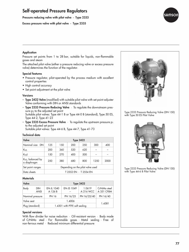
Self-operated Pressure RegulatorsPressure reducing valve with pilot valve · Type 2333
Excess pressure valve with pilot valve · Type 2335
ApplicationPressure set points from 1 to 28 bar, suitable for liquids, non-flammablegases and steamThe attached pilot valve (either a pressure reducing valve or excess pressurevalve) determines the function of the regulator.
Special features• Pressure regulator, pilot-operated by the process medium with excellent
control properties• High control accuracy• Set point adjustment at the pilot valve
Versions– Type 2422 Valve (modified) with suitable pilot valve with set point adjuster
Valve conforming with DIN or ANSI standards– Type 2333 Pressure Reducing Valve · To regulate the downstream pres-
sure p2 to the adjusted set pointSuitable pilot valves: Type 44-1 B or Type 44-0 B (standard), Type 50 ES,Type 44-2, Type 41-23
– Type 2335 Excess Pressure Valve · To regulate the upstream pressure p1
to the adjusted set pointSuitable pilot valves: Type 44-6 B, Type 44-7, Type 41-73
Technical data
Valve Type 2422
Nominal size DN 125 150 200 250 300 400
KVS 200 360 520 620 – –
KVSI 150 270 400 500 – –
KVS, balanced bya diaphragm 250 380 680 800 1250 2000
Set point ranges Depending on the pilot valve used
Data sheets T 2552 EN · T 2554 EN
Materials
Valve Type 2422
Body DINANSI
EN-JL 1040A 126 B
EN-JS 1049–
1.0619A 216 WCC
CrNiMo steelA 351 CF8M
Nominal pressure PN 16 PN 16/25 PN 16/25/40 PN 16/40
Valve seat 1.40061.4581
Plug (standard) 1.4301 with PTFE soft sealing
Special versionsWith flow divider for noise reduction · Oil-resistant version · Body madeof CrNiMo steel · For flammable gases · Metal sealing · Free ofnon-ferrous metal · Reduced minimum differential pressure
Type 2333 Pressure Reducing Valve (DN 150)with Type 50 ES Pilot Valve
Type 2333 Pressure Reducing Valve (DN 150)with Type 44-6 B Pilot Valve
77
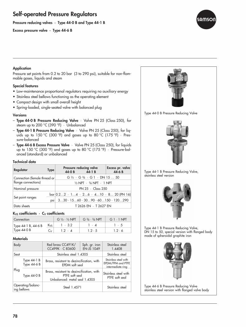
Self-operated Pressure RegulatorsPressure reducing valves · Type 44-0 B and Type 44-1 B
Excess pressure valve · Type 44-6 B
ApplicationPressure set points from 0.2 to 20 bar (3 to 290 psi), suitable for non-flam-mable gases, liquids and steam
Special features• Low-maintenance proportional regulators requiring no auxiliary energy• Stainless steel bellows functioning as the operating element• Compact design with small overall height• Spring-loaded, single-seated valve with balanced plug
Versions– Type 44-0 B Pressure Reducing Valve · Valve PN 25 (Class 250), for
steam up to 200 °C (390 °F) · Unbalanced– Type 44-1 B Pressure Reducing Valve · Valve PN 25 (Class 250), for liq-
uids up to 150 °C (300 °F) and gases up to 80 °C (175 °F) · Pres-sure-balanced
– Type 44-6 B Excess Pressure Valve · Valve PN 25 (Class 250), for liquidsup to 150 °C (300 °F) and gases up to 80 °C (175 °F) · Pressure-bal-anced (standard) or unbalanced
Technical data
Regulator Type Pressure reducing valve44-0 B 44-1 B
Excess pr. valve44-6 B
Connection (female thread orflange connections)
G ½ · G ¾ · G 1 · DN 15 … 50
½ NPT · ¾ NPT · 1 NPT
Nominal pressure PN 25 · Class 250
Set point rangesbar 0.2…2 · 1…4 · 2…6 · 4…10 · 8… 20 (PN 16)
psi 3…30 · 15…60 · 30…90 · 60…150 · 120…290
Data sheets T 2626 EN · T 2627 EN
KVS coefficients · CV coefficientsConnection G ½ · ½ NPT G ¾ · ¾ NPT G 1 · 1 NPT
Type 44-1 B, 44-6 BType 44-0 B
KVS 1 · 3.2 1 · 4 1 · 5
CV 1.2 · 4 1.2 · 5 1.2 · 6
MaterialsBody Red brass CC491K/
CC499K · C 83600Sph. gr. ironEN-JS 1049
Stainless steel1.4408
Seat Stainless steel 1.4305 Stainless steel
Plug
Type 44-1 BType 44-6 B
Brass, resistant to dezincification, withEPDM soft seal
Stainless steel withEPDM/FPM and PTFE
intermediate ring
Type 44-0 BBrass, resistant to dezincification, with
PTFE soft sealUnbalanced: metal seal 1.4305
Stainless steel withPTFE soft seal
Operating/balanc-ing bellows Steel 1.4571 Stainless steel
Type 44-0 B Pressure Reducing Valve
Type 44-1 B Pressure Reducing Valve,stainless steel version
Type 44-1 B Pressure Reducing Valve,DN 15 to 50, special version with flanged bodymade of spheroidal graphite iron
Type 44-6 B Pressure Reducing Valvestainless steel version with flanged valve body
78
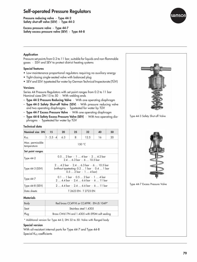
Self-operated Pressure RegulatorsPressure reducing valve · Type 44-2Safety shut-off valve (SSV) · Type 44-3
Excess pressure valve · Type 44-7Safety excess pressure valve (SEV) · Type 44-8
ApplicationPressure set points from 0.2 to 11 bar, suitable for liquids and non-flammablegases · SSV and SEV to protect district heating systems
Special features• Low-maintenance proportional regulators requiring no auxiliary energy• Tight-closing single-seated valve with balanced plug• SEV and SSV: typetested for water by German Technical Inspectorate (TÜV)
VersionsSeries 44 Pressure Regulators with set point ranges from 0.2 to 11 barNominal sizes DN 15 to 50 · With welding ends– Type 44-2 Pressure Reducing Valve · With one operating diaphragm– Type 44-3 Safety Shut-off Valve (SSV) · With pressure reducing valve
and two operating diaphragms · Typetested for water by TÜV– Type 44-7 Excess Pressure Valve · With one operating diaphragm– Type 44-8 Safety Excess Pressure Valve (SEV) · With two operating dia-
phragms · Typetested for water by TÜV
Technical data
Nominal size DN 15 20 25 32 40 50
KVS 1 · 2.5 · 4 6.3 8 12.5 16 20
Max. permissibletemperature 150 °C
Set point ranges
Type 44-2 0.5 … 2 bar · 1 … 4 bar · 2 … 4.2 bar2.4 … 6.3 bar · 6 … 10.5 bar
Type 44-3 (SSV)2 … 4.2 bar · 2.4 … 6.3 bar · 6 … 10.5 bar(without typetesting: 0.2 … 1 bar · 0.4 … 1 bar
0.5 … 2 bar · 1 … 4 bar)
Type 44-7 0.1 … 1 bar · 0.5 … 2 bar · 1 … 4 bar2 … 4.4 bar · 2.4 … 6.6 bar · 6 … 11 bar
Type 44-8 (SEV) 2 … 4.4 bar · 2.4 … 6.6 bar · 6 … 11 bar
Data sheets T 2623 EN · T 2723 EN
Materials
Body Red brass CC491K or CC499K · EN-JS 1049*
Seat Stainless steel 1.4305
Plug Brass CW617N and 1.4305 with EPDM soft sealing
* Additional version for Type 44-3, DN 32 to 50: Valve with flanged body
Special versionWith oil-resistant internal parts for Type 44-7 and Type 44-8Special KVS coefficients
Type 44-3 Safety Shut-off Valve
Type 44-7 Excess Pressure Valve
79
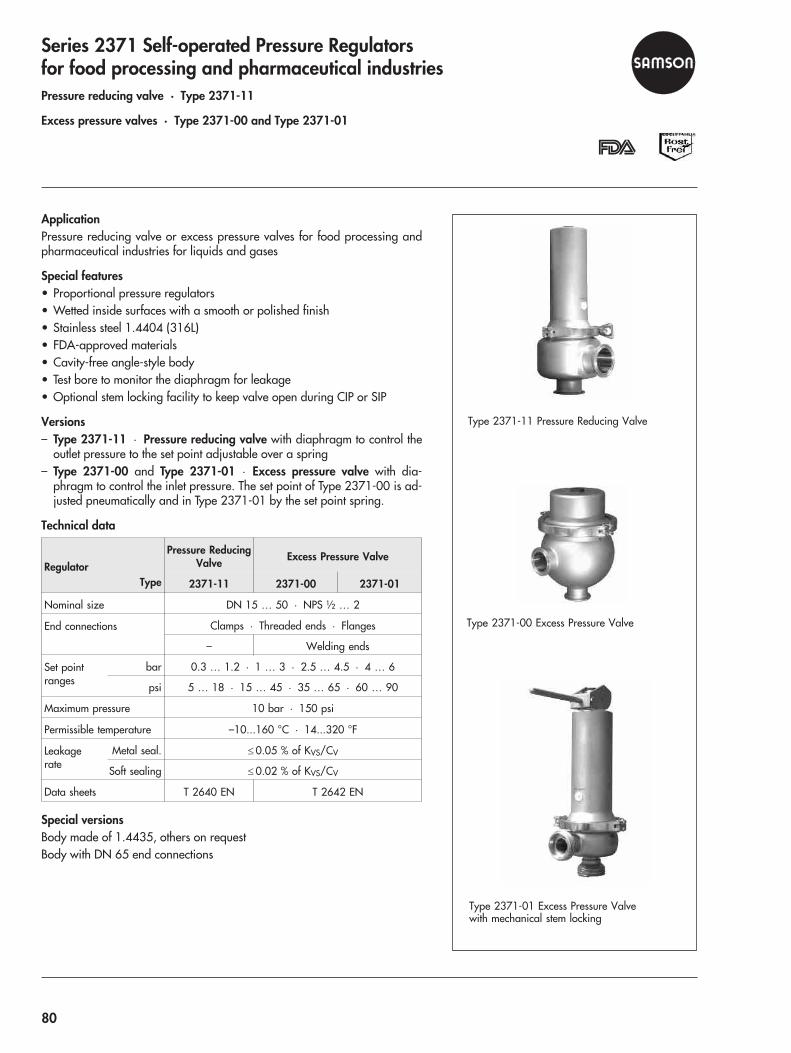
Series 2371 Self-operated Pressure Regulatorsfor food processing and pharmaceutical industriesPressure reducing valve · Type 2371-11
Excess pressure valves · Type 2371-00 and Type 2371-01
ApplicationPressure reducing valve or excess pressure valves for food processing andpharmaceutical industries for liquids and gases
Special features• Proportional pressure regulators• Wetted inside surfaces with a smooth or polished finish• Stainless steel 1.4404 (316L)• FDA-approved materials• Cavity-free angle-style body• Test bore to monitor the diaphragm for leakage• Optional stem locking facility to keep valve open during CIP or SIP
Versions– Type 2371-11 · Pressure reducing valve with diaphragm to control the
outlet pressure to the set point adjustable over a spring– Type 2371-00 and Type 2371-01 · Excess pressure valve with dia-
phragm to control the inlet pressure. The set point of Type 2371-00 is ad-justed pneumatically and in Type 2371-01 by the set point spring.
Technical data
RegulatorType
Pressure ReducingValve Excess Pressure Valve
2371-11 2371-00 2371-01
Nominal size DN 15 … 50 · NPS ½ … 2
End connections Clamps · Threaded ends · Flanges
– Welding ends
Set pointranges
bar 0.3 … 1.2 · 1 … 3 · 2.5 … 4.5 · 4 … 6
psi 5 … 18 · 15 … 45 · 35 … 65 · 60 … 90
Maximum pressure 10 bar · 150 psi
Permissible temperature –10...160 °C · 14...320 °F
Leakagerate
Metal seal. � 0.05 % of KVS/CV
Soft sealing � 0.02 % of KVS/CV
Data sheets T 2640 EN T 2642 EN
Special versionsBody made of 1.4435, others on requestBody with DN 65 end connections
Type 2371-01 Excess Pressure Valvewith mechanical stem locking
Type 2371-11 Pressure Reducing Valve
Type 2371-00 Excess Pressure Valve
80

Self-operated Flow and Differential Pressure RegulatorsCheck Valve (Backflow Prevention) · Type 42-10 RS
ApplicationFor safeguarding nitrogen and compressed air networks against backflowfrom directly connected systems.The regulator is open, provided the upstream pressure is at least 0.2 bargreater than the downstream pressure. It closes automatically when the down-stream pressure rises to or above the value of the upstream pressure.
Special features• Self-operated proportional regulator requiring little maintenance• Fixed set point, external adjustment not possible• Regulators delivered ready-to-install without supplementary devices,
meaning no additional installations or start-ups are necessary• Reliable functioning even in the event of a power failure or when other in-
struments in the control circuit malfunction• Diaphragm rupture indication, in the event of a diaphragm ruptures, the
undamaged operating diaphragm takes over the function of the damageddiaphragm
• Backflow only leads to a minimum amount of leakage due to the soft-seatedplug
• An increasing backpressure supports tight shut-off of the valve• Valve body optionally available in cast steel, cast stainless steel or forged
stainless steel• All wetted parts are free of non-ferrous metal
VersionsCheck valve in supply pipelines– Type 42-10 RS · Type 2421 RS Valve and Type 2420 RS Actuator with
two diaphragms · Fixed set point at 0.2 bar
Additional versions withDiaphragm rupture indication with pressure switchVersion made of stainless steelVersion for steam
Technical data
Type 2421 RS Valve DN 15 … 150
KVS coefficient 4 … 280
Nominal pressure PN 25 or 40
Max. constant operating pressure 25 bar
Max. permissible pressure on oneside 45 bar
Type 2420 RS Actuator
Diaphragm area 320 cm² 640 cm²
� set point, fixed 0.2 bar 0.2 bar
Max. perm. temperature Air and gases up to 80 °C
Data sheet T 3009 EN
Type 42-10 RS Check Valve
81

Self-operated Flow and Differential Pressure RegulatorsDifferential pressure regulator with balanced valve · Type 2422
- with closing actuator · Type 42-24 · Type 42-28- with opening actuator · Type 42-20 · Type 42-25
ApplicationFor district heating networks, large heating systems and industrialplants · For differential pressures from 0.05 to 10 bar (0.75 to145 psi) · Suitable for liquids and vapors as well as air and other non-flam-mable gases
Special features• Proportional regulators for district heating supply networks; single-seated
valve balanced by a stainless steel bellows or a diaphragm; low-noise andlow-maintenance
• Types 42-24 and 42-28 · Valve closes when the differential pressure rises• Types 42-20 and 42-25 · Valve opens when the differential pressure rises
Versions– Type 42-20/Type 42-28 A
Type 2422 Valve, DN 15 to 100 · NPS ½ to 4Type 2420/Type 2428 Actuator with fixed set point
– Type 42-25/Type 42-24 AType 2422 Valve, DN 15 to 250 · NPS ½ to 10Type 2425/Type 2424 Actuator with adjustable set point
– Type 42-24 BType 2422 Valve, DN 15 to 250 · NPS ½ to 10Distance piece and Type 2424 Actuator with adjustable set point
– Type 42-28 BType 2422 Valve, DN 15 to 100 · NPS ½ to 4Distance piece and Type 2428 Actuator with fixed set point
Technical data
Type 42-24 42-25 42-28 42-20
Nominal size DN 15 … 250 · NPS ½… 10 DN 15 … 100 · NPS ½... 4
Set point ranges �p
0.05 … 0.25 bar to4.5 … 10 bar
0.2 · 0.3 · 0.4 · 0.5 barFixed set point
0.75 … 3.5 psi to65 … 145 psi
3 · 4 · 6 · 7 psiFixed set point
Data sheets T 3003 EN/3004 EN · T3007 EN/3008 EN
Materials
Valve Type 2422
Valve body* DIN EN-JL 1040 EN-JS 1049 1.0619 1.4581
ANSI A 126 B – A 216 WCC A 351 CF8M
Nominal pressure PN 16Class 125
PN 25–
PN 25/40Class 150/300
Actuator Type 2420/2424/2425/2428
Diaphragm cases DD 11
Diaphragm EPDM with fabric insert
* Also in corrosion-resistant forged steel 1.4571 for DN 15, 25, 40 and 50
Type 42-24 A Differential Pressure Regulator
Type 42-25 Differential Pressure Regulator
Type 42-28 A Differential Pressure Regulator
82
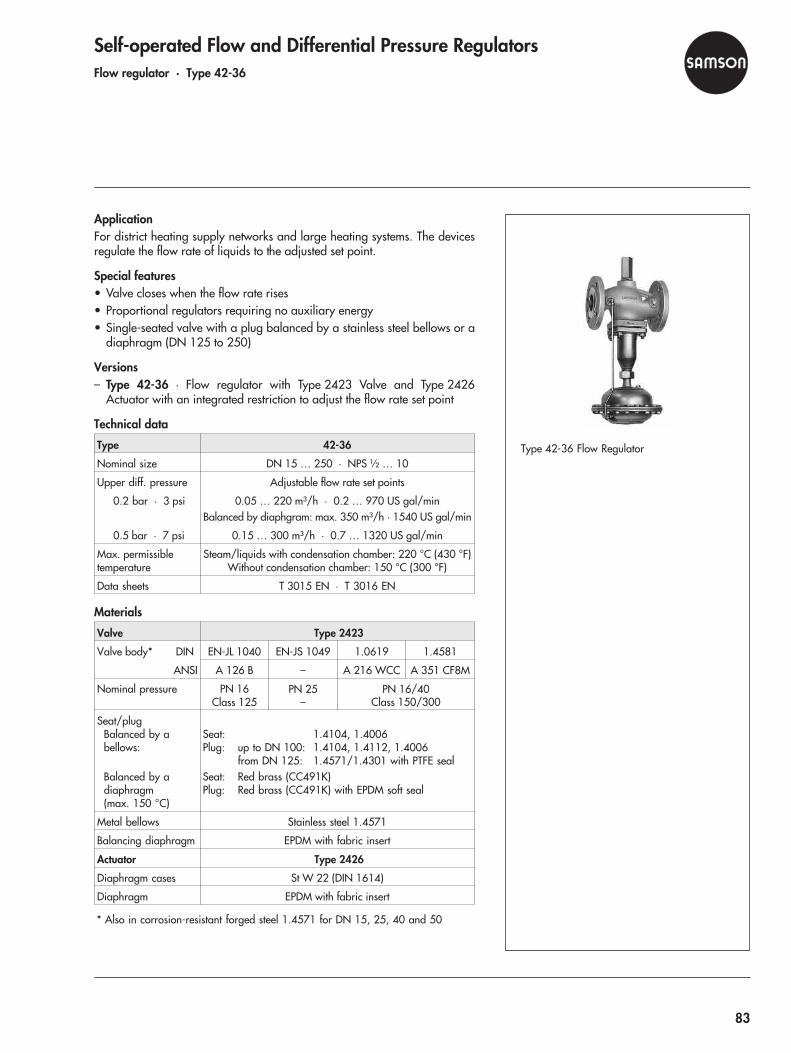
Self-operated Flow and Differential Pressure RegulatorsFlow regulator · Type 42-36
ApplicationFor district heating supply networks and large heating systems. The devicesregulate the flow rate of liquids to the adjusted set point.
Special features• Valve closes when the flow rate rises• Proportional regulators requiring no auxiliary energy• Single-seated valve with a plug balanced by a stainless steel bellows or a
diaphragm (DN 125 to 250)
Versions– Type 42-36 · Flow regulator with Type 2423 Valve and Type 2426
Actuator with an integrated restriction to adjust the flow rate set point
Technical data
Type 42-36
Nominal size DN 15 … 250 · NPS ½ … 10
Upper diff. pressure Adjustable flow rate set points
0.2 bar · 3 psi 0.05 … 220 m³/h · 0.2 … 970 US gal/minBalanced by diaphgram: max. 350 m³/h · 1540 US gal/min
0.5 bar · 7 psi 0.15 … 300 m³/h · 0.7 … 1320 US gal/min
Max. permissibletemperature
Steam/liquids with condensation chamber: 220 °C (430 °F)Without condensation chamber: 150 °C (300 °F)
Data sheets T 3015 EN · T 3016 EN
Materials
Valve Type 2423
Valve body* DIN EN-JL 1040 EN-JS 1049 1.0619 1.4581
ANSI A 126 B – A 216 WCC A 351 CF8M
Nominal pressure PN 16Class 125
PN 25–
PN 16/40Class 150/300
Seat/plugBalanced by abellows:
Balanced by adiaphragm(max. 150 °C)
Seat: 1.4104, 1.4006Plug: up to DN 100: 1.4104, 1.4112, 1.4006
from DN 125: 1.4571/1.4301 with PTFE sealSeat: Red brass (CC491K)Plug: Red brass (CC491K) with EPDM soft seal
Metal bellows Stainless steel 1.4571
Balancing diaphragm EPDM with fabric insert
Actuator Type 2426
Diaphragm cases St W 22 (DIN 1614)
Diaphragm EPDM with fabric insert
* Also in corrosion-resistant forged steel 1.4571 for DN 15, 25, 40 and 50
Type 42-36 Flow Regulator
83
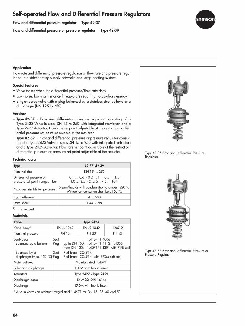
Self-operated Flow and Differential Pressure RegulatorsFlow and differential pressure regulator · Type 42-37
Flow and differential pressure or pressure regulator · Type 42-39
ApplicationFlow rate and differential pressure regulation or flow rate and pressure regu-lation in district heating supply networks and large heating systems
Special features• Valve closes when the differential pressure/flow rate rises• Low-noise, low-maintenance P regulators requiring no auxiliary energy• Single-seated valve with a plug balanced by a stainless steel bellows or a
diaphragm (DN 125 to 250)
Versions– Type 42-37 · Flow and differential pressure regulator consisting of a
Type 2423 Valve in sizes DN 15 to 250 with integrated restriction and aType 2427 Actuator. Flow rate set point adjustable at the restriction; differ-ential pressure set point adjustable at the actuator
– Type 42-39 · Flow and differential pressure or pressure regulator consist-ing of a Type 2423 Valve in sizes DN 15 to 250 with integrated restrictionand a Type 2429 Actuator. Flow rate set point adjustable at the restriction;differential pressure or pressure set point adjustable at the actuator
Technical data
Type 42-37, 42-39
Nominal size DN 15 … 250
Differential pressure orpressure set point ranges bar
0.1 … 0.6 · 0.2 … 1 · 0.5 … 1.51.0 … 2.5 · 2 … 5 · 4.5 … 10 1)
Max. permissible temperature Steam/liquids with condensation chamber: 220 °CWithout condensation chamber: 150 °C
KVS coefficients 4 … 500
Data sheet T 3017 EN1) On request
Materials
Valve Type 2423
Valve body* EN-JL 1040 EN-JS 1049 1.0619
Nominal pressure PN 16 PN 25 PN 40
Seat/plugBalanced by a bellows:
Balanced by adiaphragm (max. 150 °C)
Seat: 1.4104, 1.4006Plug: up to DN 100: 1.4104, 1.4112, 1.4006
from DN 125: 1.4571/1.4301 with PTFE sealSeat: Red brass (CC491K)Plug: Red brass (CC491K) with EPDM soft seal
Metal bellows Stainless steel 1.4571
Balancing diaphragm EPDM with fabric insert
Actuators Type 2427 · Type 2429
Diaphragm cases St W 22 (DIN 1614)
Diaphragm EPDM with fabric insert
* Also in corrosion-resistant forged steel 1.4571 for DN 15, 25, 40 and 50
Type 42-37 Flow and Differential PressureRegulator
Type 42-39 Flow and Differential Pressure orPressure Regulator
84
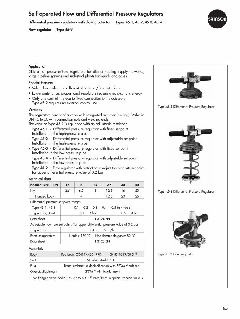
Self-operated Flow and Differential Pressure RegulatorsDifferential pressure regulators with closing actuator · Types 45-1, 45-2, 45-3, 45-4
Flow regulator · Type 45-9
ApplicationDifferential pressure/flow regulators for district heating supply networks,large pipeline systems and industrial plants for liquids and gases
Special features• Valve closes when the differential pressure/flow rate rises• Low-maintenance, proportional regulators requiring no auxiliary energy• Only one control line due to fixed connection to the actuator;
Type 45-9 requires no external control line
VersionsThe regulators consist of a valve with integrated actuator (closing). Valve inDN 15 to 50 with connection nuts and welding ends.The valve of Type 45-9 is equipped with an adjustable restriction.– Type 45-1 · Differential pressure regulator with fixed set point
Installation in the high-pressure pipe– Type 45-2 · Differential pressure regulator with adjustable set point
Installation in the high-pressure pipe– Type 45-3 · Differential pressure regulator with fixed set point
Installation in the low-pressure pipe– Type 45-4 · Differential pressure regulator with adjustable set point
Installation in the low-pressure pipe– Type 45-9 · Flow regulator with restriction to adjust the flow rate set point
for upper differential pressure value of 0.2 bar
Technical dataNominal size DN 15 20 25 32 40 50
KVS 2.5 6.3 8 12.5 16 20
Flanged body – 12.5 20 25
Differential pressure set point ranges
Type 45-1, 45-3 0.1 · 0.2 · 0.3 · 0.4 · 0.5 bar fixed
Type 45-2, 45-4 0.1 … 4 bar 0.2 … 4 bar
Data sheet T 3124 EN
Adjustable flow rate set points (for upper differential pressure value of 0.2 bar)
Type 45-9 0.01 … 15 m³/h
Perm. temperature Liquids: 150 °C · Non-flammable gases: 80 °C
Data sheet T 3128 EN
MaterialsBody Red brass CC491K/CC499K EN-JS 1049/395 1)
Seat Stainless steel 1.4305
Plug Brass, resistant to dezincification with EPDM 2) soft seal
Operat. diaphragm EPDM 2) with fabric insert
1) For flanged valve bodies DN 32 to 50 · 2) FPM/FKM in special version for oils
Type 45-3 Differential Pressure Regulator
Type 45-4 Differential Pressure Regulator
Type 45-9 Flow Regulator
85
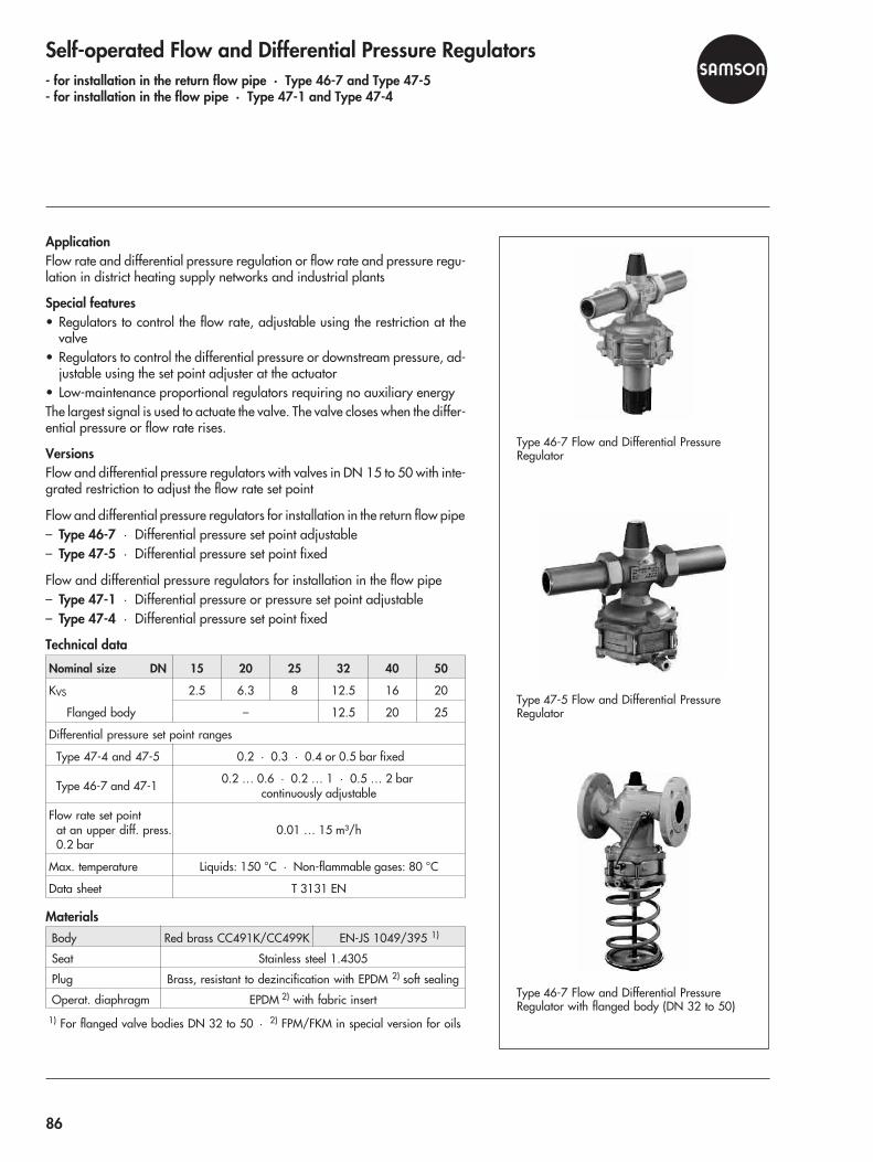
Self-operated Flow and Differential Pressure Regulators- for installation in the return flow pipe · Type 46-7 and Type 47-5- for installation in the flow pipe · Type 47-1 and Type 47-4
ApplicationFlow rate and differential pressure regulation or flow rate and pressure regu-lation in district heating supply networks and industrial plants
Special features• Regulators to control the flow rate, adjustable using the restriction at the
valve• Regulators to control the differential pressure or downstream pressure, ad-
justable using the set point adjuster at the actuator• Low-maintenance proportional regulators requiring no auxiliary energyThe largest signal is used to actuate the valve. The valve closes when the differ-ential pressure or flow rate rises.
VersionsFlow and differential pressure regulators with valves in DN 15 to 50 with inte-grated restriction to adjust the flow rate set point
Flow and differential pressure regulators for installation in the return flow pipe– Type 46-7 · Differential pressure set point adjustable– Type 47-5 · Differential pressure set point fixed
Flow and differential pressure regulators for installation in the flow pipe– Type 47-1 · Differential pressure or pressure set point adjustable– Type 47-4 · Differential pressure set point fixed
Technical data
Nominal size DN 15 20 25 32 40 50
KVS 2.5 6.3 8 12.5 16 20
Flanged body – 12.5 20 25
Differential pressure set point ranges
Type 47-4 and 47-5 0.2 · 0.3 · 0.4 or 0.5 bar fixed
Type 46-7 and 47-1 0.2 … 0.6 · 0.2 … 1 · 0.5 … 2 barcontinuously adjustable
Flow rate set pointat an upper diff. press.0.2 bar
0.01 … 15 m³/h
Max. temperature Liquids: 150 °C · Non-flammable gases: 80 °C
Data sheet T 3131 EN
MaterialsBody Red brass CC491K/CC499K EN-JS 1049/395 1)
Seat Stainless steel 1.4305
Plug Brass, resistant to dezincification with EPDM 2) soft sealing
Operat. diaphragm EPDM 2) with fabric insert
1) For flanged valve bodies DN 32 to 50 · 2) FPM/FKM in special version for oils
Type 46-7 Flow and Differential PressureRegulator
Type 47-5 Flow and Differential PressureRegulator
Type 46-7 Flow and Differential PressureRegulator with flanged body (DN 32 to 50)
86

Combined Self-operated Flow Regulatorswith an additional electric actuatorFlow regulator · Type 42-36 E
ApplicationSelf-operated flow regulator in district heating supply networks or extendedheating networks. Combined with an electric actuator to apply the control sig-nal issued by electric control equipment.
Special featuresThe valve closes when the flow rate rises. In addition, the control signal of elec-tric control equipment can be applied to influence the flow rate over the actua-tor. The largest signal is used to actuate the valve.
The device combinations consist of:• Valve with flanged body• Diaphragm actuator• Adapter to attach the electric actuator and to adjust the flow rate• Control equipment typetested according to DIN EN 14597 available
VersionsValves DN 15 to 250 · Nominal pressure PN 16 to 40 · Suitable for liquidsfrom 5 to 150 °C · Electric actuators with or without fail-safe action to changethe flow rate set point depending on the control signal issued by electric con-trol equipment– Type 42-36 E · Flow regulator with restriction to adjust the flow rate set
point · Installation in the flow or return flow pipe
Technical data
Type 42-36 E
Nominal size DN 15 … 250
Nominal pressure PN 16, 25, 40 (acc. to DIN EN 12516-1)
Flow rateset point ranges
Upper diff. pressure 0.2 bar: 2 to 220 m³/h
Upper diff. pressure 0.5 bar: 3 to 300 m³/h
TemperaturesMax. permissible medium temperature: 150 °C
Max. permissible ambient temperature: 50 °C
KVS coefficients 4 … 800
Data sheet T 3018 EN
Type 42-36 E Flow Regulatorwith Type 5825 Actuator
87
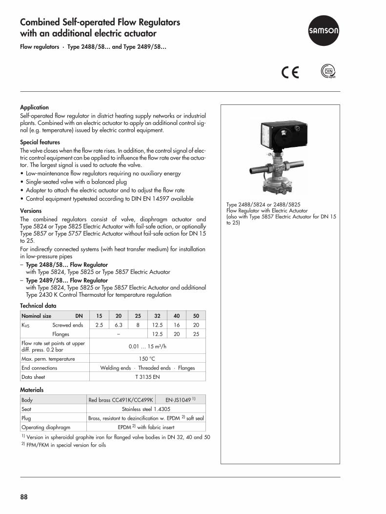
Combined Self-operated Flow Regulatorswith an additional electric actuatorFlow regulators · Type 2488/58… and Type 2489/58…
ApplicationSelf-operated flow regulator in district heating supply networks or industrialplants. Combined with an electric actuator to apply an additional control sig-nal (e.g. temperature) issued by electric control equipment.
Special featuresThe valve closes when the flow rate rises. In addition, the control signal of elec-tric control equipment can be applied to influence the flow rate over the actua-tor. The largest signal is used to actuate the valve.• Low-maintenance flow regulators requiring no auxiliary energy• Single-seated valve with a balanced plug• Adapter to attach the electric actuator and to adjust the flow rate• Control equipment typetested according to DIN EN 14597 available
VersionsThe combined regulators consist of valve, diaphragm actuator andType 5824 or Type 5825 Electric Actuator with fail-safe action, or optionallyType 5857 or Type 5757 Electric Actuator without fail-safe action for DN 15to 25.For indirectly connected systems (with heat transfer medium) for installationin low-pressure pipes– Type 2488/58… Flow Regulator
with Type 5824, Type 5825 or Type 5857 Electric Actuator– Type 2489/58… Flow Regulator
with Type 5824, Type 5825 or Type 5857 Electric Actuator and additionalType 2430 K Control Thermostat for temperature regulation
Technical data
Nominal size DN 15 20 25 32 40 50
KVS Screwed ends 2.5 6.3 8 12.5 16 20
Flanges – 12.5 20 25
Flow rate set points at upperdiff. press. 0.2 bar 0.01 … 15 m³/h
Max. perm. temperature 150 °C
End connections Welding ends · Threaded ends · Flanges
Data sheet T 3135 EN
Materials
Body Red brass CC491K/CC499K EN-JS1049 1)
Seat Stainless steel 1.4305
Plug Brass, resistant to dezincification w. EPDM 2) soft seal
Operating diaphragm EPDM 2) with fabric insert1) Version in spheroidal graphite iron for flanged valve bodies in DN 32, 40 and 502) FPM/FKM in special version for oils
Type 2488/5824 or 2488/5825Flow Regulator with Electric Actuator(also with Type 5857 Electric Actuator for DN 15to 25)
88
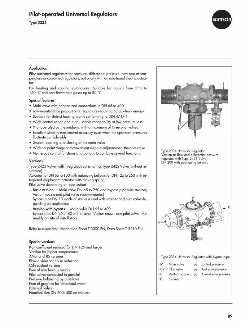
Pilot-operated Universal RegulatorsType 2334
ApplicationPilot-operated regulators for pressure, differential pressure, flow rate or tem-perature or combined regulators, optionally with an additional electric actua-torFor heating and cooling installations · Suitable for liquids from 5 °C to150 °C and non-flammable gases up to 80 °C
Special features• Main valve with flanged end connections in DN 65 to 400• Low-maintenance proportional regulators requiring no auxiliary energy• Suitable for district heating plants conforming to DIN 4747-1• Wide control range and high useable rangeability at low pressure loss• Pilot-operated by the medium, with a maximum of three pilot valves• Excellent stability and control accuracy even when the upstream pressures
fluctuate considerably• Smooth opening and closing of the main valve• Wide set point range and convenient set point adjustment at the pilot valve• Numerous control functions and options to combine several functions
VersionsType 2423 Valve (with integrated restriction) or Type 2422 Valve (without re-striction)Actuator for DN 65 to 100 with balancing bellows for DN 125 to 250 with in-tegrated diaphragm actuator with closing springPilot valve depending on application– Basic version · Main valve DN 65 to 250 and bypass pipe with strainer,
Venturi nozzle and pilot valve ready-mountedBypass pipe DN 10 made of stainless steel with strainer and pilot valve de-pending on application
– Version with bypass · Main valve DN 65 to 400Bypass pipe DN 25 or 40 with strainer, Venturi nozzle and pilot valve · As-sembly on site of installation
Refer to associated Information Sheet T 3000 EN, Data Sheet T 3210 EN
Special versionsKVS coefficient reduced for DN 125 and largerVersion for higher temperaturesANSI and JIS versionsFlow divider for noise reductionOil-resistant versionFree of non-ferrous metalsPilot valves connected in parallelPressure balancing by a bellowsFree of graphite for deionized waterExternal orificeNominal size DN 300/400 on request
Type 2334 Universal RegulatorVersion as flow and differential pressureregulator with Type 2422 Valve,DN 200 with positioning bellows
P1
SFDE
HSV
HV
P2
PS
Type 2334 Universal Regulator with bypass pipe
HV Main valve ps Control pressureHSV Pilot valve p1 Upstream pressureDE Venturi nozzle p2 Downstream pressureSF Strainer
89
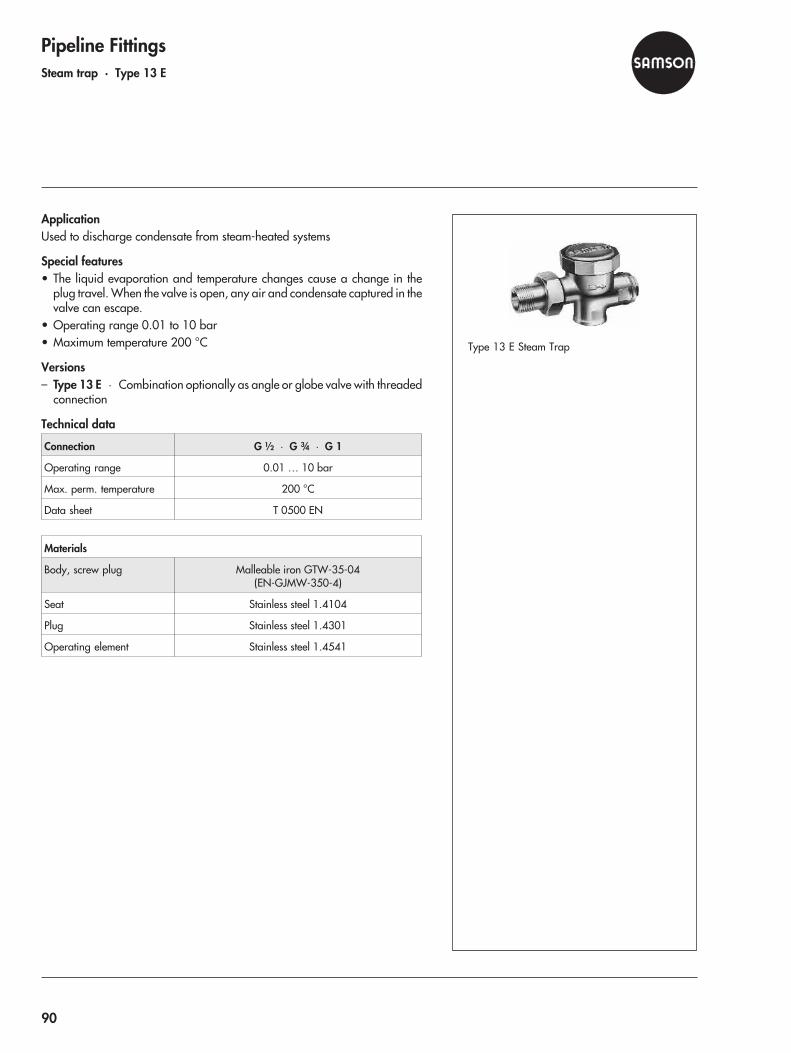
Pipeline FittingsSteam trap · Type 13 E
ApplicationUsed to discharge condensate from steam-heated systems
Special features• The liquid evaporation and temperature changes cause a change in the
plug travel. When the valve is open, any air and condensate captured in thevalve can escape.
• Operating range 0.01 to 10 bar• Maximum temperature 200 °C
Versions– Type 13 E · Combination optionally as angle or globe valve with threaded
connection
Technical data
Connection G ½ · G ¾ · G 1
Operating range 0.01 … 10 bar
Max. perm. temperature 200 °C
Data sheet T 0500 EN
Materials
Body, screw plug Malleable iron GTW-35-04(EN-GJMW-350-4)
Seat Stainless steel 1.4104
Plug Stainless steel 1.4301
Operating element Stainless steel 1.4541
Type 13 E Steam Trap
90
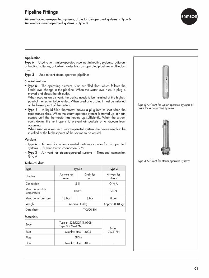
Pipeline FittingsAir vent for water-operated systems, drain for air-operated systems · Type 6Air vent for steam-operated systems · Type 3
ApplicationType 6 · Used to vent water-operated pipelines in heating systems, radiatorsor heating batteries, or to drain water from air-operated pipelines in all indus-triesType 3 · Used to vent steam-operated pipelines
Special features• Type 6 · The operating element is an air-filled float which follows the
liquid level change in the pipeline. When the water level rises, a plug ismoved and closes the air outlet.When used as an air vent, the device needs to be installed at the highestpoint of the section to be vented. When used as a drain, it must be installedat the lowest point of the system.
• Type 3 · A liquid-filled thermostat moves a plug into its seat when thetemperature rises. When the steam-operated system is started up, air canescape until the thermostat has heated up sufficiently. When the systemcools down, the vent opens to prevent air pockets or a vacuum fromoccurring.When used as a vent in a steam-operated system, the device needs to beinstalled at the highest point of the section to be vented.
Versions– Type 6 · Air vent for water-operated systems or drain for air-operated
systems · Female thread connection G ½– Type 3 · Air vent for steam-operated systems · Threaded connection
G ½ A
Technical data
Type Type 6 Type 3
Used as Air vent forwater
Drain forair
Air vent forsteam
Connection G ½ G ½ A
Max. permissibletemperature 180 °C 170 °C
Max. perm. pressure 16 bar 8 bar 8 bar
Weight Approx. 1.3 kg Approx. 0.18 kg
Data sheet T 0500 EN
Materials
Body Type 6: S235G2T (1.0308)Type 3: CW617N
BrassCW617NSeat Stainless steel 1.4006
Plug EPDM
Float Stainless steel 1.4006 –
Type 6 Air Vent for water-operated systems ordrain for air-operated systems
Type 3 Air Vent for steam-operated systems
91
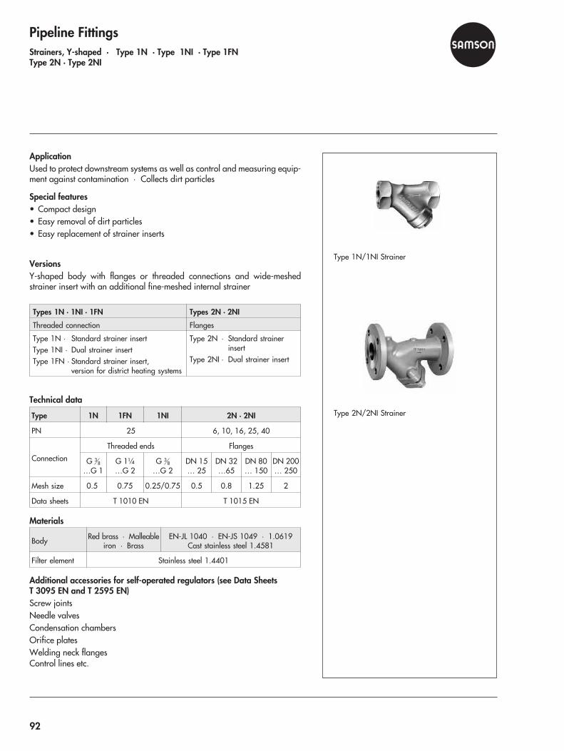
Pipeline FittingsStrainers, Y-shaped · Type 1N · Type 1NI · Type 1FNType 2N · Type 2NI
ApplicationUsed to protect downstream systems as well as control and measuring equip-ment against contamination · Collects dirt particles
Special features• Compact design• Easy removal of dirt particles• Easy replacement of strainer inserts
VersionsY-shaped body with flanges or threaded connections and wide-meshedstrainer insert with an additional fine-meshed internal strainer
Types 1N · 1NI · 1FN Types 2N · 2NI
Threaded connection Flanges
Type 1N · Standard strainer insertType 1NI · Dual strainer insertType 1FN · Standard strainer insert,
version for district heating systems
Type 2N · Standard strainerinsert
Type 2NI · Dual strainer insert
Technical data
Type 1N 1FN 1NI 2N · 2NI
PN 25 6, 10, 16, 25, 40
Connection
Threaded ends Flanges
G 38
…G 1G 1¼…G 2
G 38
…G 2DN 15… 25
DN 32…65
DN 80… 150
DN 200… 250
Mesh size 0.5 0.75 0.25/0.75 0.5 0.8 1.25 2
Data sheets T 1010 EN T 1015 EN
Materials
Body Red brass · Malleableiron · Brass
EN-JL 1040 · EN-JS 1049 · 1.0619Cast stainless steel 1.4581
Filter element Stainless steel 1.4401
Additional accessories for self-operated regulators (see Data SheetsT 3095 EN and T 2595 EN)Screw jointsNeedle valvesCondensation chambersOrifice platesWelding neck flangesControl lines etc.
Type 1N/1NI Strainer
Type 2N/2NI Strainer
92
Control valves for industrial processes
Globe, three-way and angle valves
Butterfly control valves
Steam-converting valves
Actuators
Positioners
Limit switches, solenoid valves, converters, etc.
Self-operated regulators and accessories for piping systems
Temperature regulators
Pressure regulators
Differential pressure and flow regulators
Boiler regulators
Steam traps
Strainers
Air vents
Control valves for heating, ventilation and air-conditioning systems
Electric actuators
Control valves
Control valves with jet pumps
Combined self-operated regulators with electric actuators
Controllers and sensors for heating, ventilation and air-conditioning systems
Electronic controllers
Sensors, converters and controllers
Automation systems TROVIS · Process control systems on Windows
TROVIS MODULON · Distributed automation system with communication via Ethernet and LON
TROVIS 6600 · Automation system with native BACnet
Pneumatic and electric measuring and control equipment for process automation
Series 430 · Pneumatic indicating controllers
Series 420 · Pneumatic control system
Media · Liquid level, differential pressure and flow meters
Sensors
Converters
TROVIS 6400 · Automation system
SAMSOMATIC product range Logic elements and accessories for pneumatic controls
Design and supply of factory-assembled automation packages
SAMSON Product Range
Appendix
93


Valve sizingCalculation of the KV coefficientThe KV coefficient is calculated according to IEC 60534. Thedata sheets contain the required valve-specific data.A preliminary simplified calculation may be made with the helpof the working equations listed below. They do not take into ac-count the influences of the attached fittings and turbulentchoked flow.
Valve selectionAfter calculating the KV coefficient, the KVS coefficient of thevalve type concerned needs to be selected from the data sheet.If real operating data have been used for calculation, the fol-lowing applies:KVmax ≈ 0.7 to 0.8 x KVS
Medium Liquids Gases Steam
Pressure drop m³/h kg/h m³/h kg/h kg/h
p2 >p1
2
KV = Qρ
Δ1000 pKV =
Wp1000 ρ Δ
KV =QG
519ρ
ΔG Tp p
1
2
KV =W519
Tp pG
1
2ρ ΔKV =
W3162.
vp2
ΔΔp <
p1
2
p2 <p1
2KV =
Qp
G
2595 1.ρG T1 KV =
Wp2595 1.
T
G
1
ρKV =
W3162.
21
vp
*
Δp >p1
2
Symbols used:p1 [bar] Absolute pressure pabs
p2 [bar] Absolute pressure pabs
Δp [bar] Differential pressureT1 [K] 273 + t1QG [m³/h] Flow rate of gases at 0 °C and 1013 mbar
ρ [kg/m³] Density of liquidsρG [kg/m³] Density of gases at 0 °C and 1013 mbarv1 [m³/kg] Specific volume (v´ from steam table) for p1 and t1v2 [m³/kg] Specific volume (v´ from steam table) for p2 and t1v* [m³/kg] Specific volume (v´ from steam table) for
p1
2 and t1
p1 Upstream pressurep2 Downstream pressureH TravelQ Volumetric flow rate in m³/hW Mass flow rate in kg/hρ Density in kg/m³
(generally also for liquids)ρ1 Upstream density in kg/m³
(for gases and vapors)t1 Temperature in °C upstream of the valve
95


Data Sheet for Control Valves ⋅according to DIN EN 60 534-7
Data Sheet for Control Valves ( - Minimum details for the selection and the sizing of one valve)
1
Ope
ratin
g da
ta
Site of control2 Measuring and control task7 Pipeline DN ... PN ... Class ...8 Pipe material
12 Process medium13 State at the input - liquid - steam - vapor
15 min. standard max. unit16 Flow rate17 Input pressure p1
18 Output pressure p2
19 Temperature T120 Input density p1 or M21 Steam pressure Pv
22 Critical pressure Pc
23 Kinematic viscosity v31 Calculation of max. flow rate coefficient Kv
32 Calculation of min. flow rate coefficient Kv
33 Selected flow rate coefficient Kvs
34 Calculated sound pressure level ... dB(A) 35
Valv
e bo
dy
Control Valve Type36 Style38 Nominal pressure PN ...39 Nominal size DN ...40 Type of connection - flange - welding end - welded-neck end - DIN / - ANSI43 Bonnet shape - standard - insulating section - bellows seal - heating jacket45 Body/bonnet material47 Characteristic - linear - equal percentage48 Plug/stem material49 Bushing/seat material52 Hard facing - none - partly stellited - purely stellited - hardened54 Leakage class ... % Kvs class ...55 Packing material - standard - type
57
Act
uato
r
Actuator type - pneumatic
60 Effective area ... cm2
62 Supply air pressure min. max.63 Bench range64 Fail-safe action - closed - open - stop66 Other operating mode - electric - electrohydraulic - hand-operated67 Fail-safe action with three-way valve68 Additional manual operation - no - yes
70
Posit
ione
r
Positioner Type71 Input signal - pneumatic - electric72 Control valve opened at ... bar ... mA73 Control valve closed at ... bar ... mA76 Air connection max. ... bar78 Explosion protection - EExi - Exd80
Limit
switc
h
Limit switch Type81 Limit switch - electric - inductive - pneumatic82 Switching position - closed - % travel - open83 Switching function - closing - opening84 Explosion protection - EExi - EExd86
Sole
noid
val
ve
Solenoid valve Type87 Style - 2-way - 3-way88 If power fails, valve should - open - close - stop
91 Electric data ... V ... Hz ... W
97

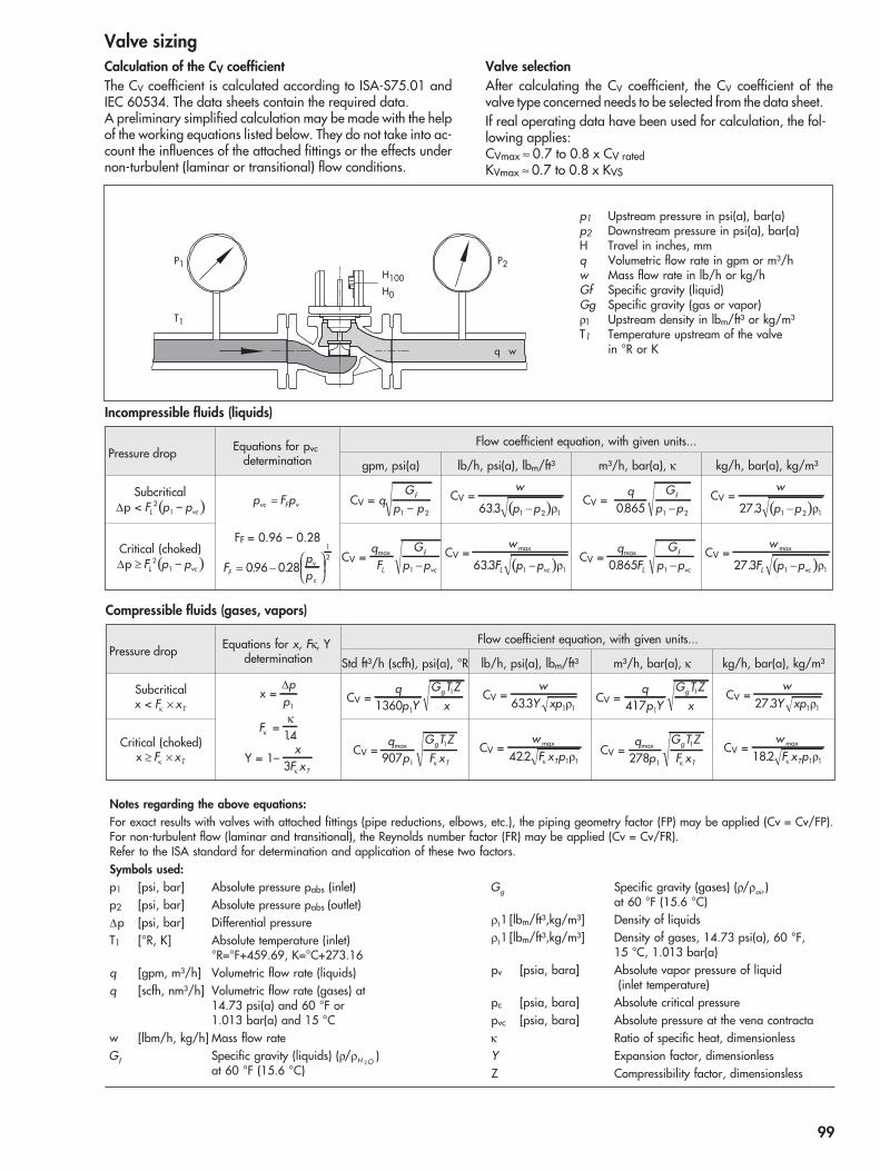
Valve sizingCalculation of the CV coefficientThe CV coefficient is calculated according to ISA-S75.01 andIEC 60534. The data sheets contain the required data.A preliminary simplified calculation may be made with the helpof the working equations listed below. They do not take into ac-count the influences of the attached fittings or the effects undernon-turbulent (laminar or transitional) flow conditions.
Valve selectionAfter calculating the CV coefficient, the CV coefficient of thevalve type concerned needs to be selected from the data sheet.If real operating data have been used for calculation, the fol-lowing applies:CVmax ≈ 0.7 to 0.8 x CV ratedKVmax ≈ 0.7 to 0.8 x KVS
Pressure drop Equations for pvcdetermination
Flow coefficient equation, with given units...
gpm, psi(a) lb/h, psi(a), lbm/ft³ m³/h, bar(a), κ kg/h, bar(a), kg/m³
SubcriticalΔp < ( )F p pL vc
21 – p F pvc F v= CV = q
Gp p
f
1 2–CV =
( )w
p p633 1 2 1. − ρCV =
q Gp p
f
0865 1 2. −CV =
( )w
p p27 3 1 2 1. − ρ
Critical (choked)Δp ( )≥ F p pL vc
21 –
FF = 0.96 – 0.28
FppF
v
c= −
⎛⎝⎜
⎞⎠⎟096 028
12
. .CV =
qF
Gp pL
f
vc
max
1 −CV =
( )w
F p pL vc
max
.633 1 1− ρCV =
qF
Gp pL
f
vc
max
.0865 1 −CV =
( )w
F p pL vc
max
.27 3 1 1− ρ
Incompressible fluids (liquids)
q w
T1
P1 P2H100H0
p1 Upstream pressure in psi(a), bar(a)p2 Downstream pressure in psi(a), bar(a)H Travel in inches, mmq Volumetric flow rate in gpm or m³/hw Mass flow rate in lb/h or kg/hGf Specific gravity (liquid)Gg Specific gravity (gas or vapor)ρ1 Upstream density in lbm/ft³ or kg/m³T1 Temperature upstream of the valve
in °R or K
Notes regarding the above equations:For exact results with valves with attached fittings (pipe reductions, elbows, etc.), the piping geometry factor (FP) may be applied (Cv = Cv/FP).For non-turbulent flow (laminar and transitional), the Reynolds number factor (FR) may be applied (Cv = Cv/FR).Refer to the ISA standard for determination and application of these two factors.Symbols used:p1 [psi, bar] Absolute pressure pabs (inlet)p2 [psi, bar] Absolute pressure pabs (outlet)Δp [psi, bar] Differential pressureT1 [°R, K] Absolute temperature (inlet)
°R=°F+459.69, K=°C+273.16q [gpm, m³/h] Volumetric flow rate (liquids)q [scfh, nm³/h] Volumetric flow rate (gases) at
14.73 psi(a) and 60 °F or1.013 bar(a) and 15 °C
w [lbm/h, kg/h] Mass flow rateGf Specific gravity (liquids) (ρ/ρH O2
)at 60 °F (15.6 °C)
Gg Specific gravity (gases) (ρ/ρair )at 60 °F (15.6 °C)
ρ11 [lbm/ft³,kg/m³] Density of liquidsρ11 [lbm/ft³,kg/m³] Density of gases, 14.73 psi(a), 60 °F,
15 °C, 1.013 bar(a)pv [psia, bara] Absolute vapor pressure of liquid
(inlet temperature)pc [psia, bara] Absolute critical pressurepvc [psia, bara] Absolute pressure at the vena contractaκ Ratio of specific heat, dimensionlessY Expansion factor, dimensionlessZ Compressibility factor, dimensionsless
Pressure drop Equations for x, Fκ, Ydetermination
Flow coefficient equation, with given units...
Std ft³/h (scfh), psi(a), °R lb/h, psi(a), lbm/ft³ m³/h, bar(a), κ kg/h, bar(a), kg/m³
Subcriticalx < F xTκ ×
x =Δpp1
Fκ =κ
14.
Y = 1–x
F xT3 κ
CV =q
p YG T Z
xg
1360 1
1 CV =w
Y xp633 1 1. ρ CV =qp Y
G T Zx
g
417 1
1 CV =w
Y xp27 3 1 1. ρ
Critical (choked)x ≥ ×F xTκ
CV =q
pG T ZF x
g
T
max
907 1
1
κ
CV =wF x pT
max
.422 1 1κ ρ CV =q
pG T ZF x
g
T
max
278 1
1
κ
CV =wF x pT
max
.182 1 1κ ρ
Compressible fluids (gases, vapors)
99


Project Data Sheet ofUnit DateP.O. SpecItem TagContract DwgMfr Serial* Service
1 FluidUnits Min Flow
2 Flow Rate –3 Inlet Pressure4 Outlet Pressure5 Inlet Temperature6 Density/Spec Grav/Mol Wt –7 Viscosity/Spec Heat Ratio –8 Vapor Pressure Pv –9 equired Cv –
10 * Travel %11 Allowable/*Predicted SPL dB(A) –12
13 Pipe Line Size In 53 ype14 & Schedule Out 54 * Mfr & Model15 Pipeline Insulation 55 * Size Eff Area
56 On/Off Modulating16 ype 57 Spring Action Open/Close17 * Size ANSI Class 58 * Max Allowable Pressure18 Max Press/Temp 59 * Min Required Pressure19 * Mfr & Model 6020 * Body/Bonnet Matl 6121 * Liner Matl/ID 62 *22 63 Act Orientation23 64 Handwheel T ype24 65 Air Fails Valve Set at25 End Ext/Matl 6626 * Flow Direction 6727 ype of Bonnet28 Lub & Iso Valve Lube 68 ype29 * Packing Material 69 * Mfr & Model30 * Packing Type 70 *31 71 Gauges Bypass
72 * Cam Characteristic32 7333 * Size Rated Travel34 74 Type Quantity35 * Balanced/Unbalanced 75 * Mfr & Model36 * Rated Cv FL XT 76 Contacts/Rating37 * Plug/Ball/Disk Material 77 Actuation Points38 * Seat Material 783940 * Stem Material 79 fr & Model41 80 * Set Pressure42 81 Filter Gauges
8243 Group Div.44 83 ydrostatic Pressure45 84 ANSI/FCI Leakage Class46 8547 8648 Revision Orig49505152
Date
End InConnection Out
Available Instr. Air MaxSupply Pressure Min
SERV
ICE
CON
DITI
ON
S
ACT
UATO
R
LINE
VALV
EBO
DY/
BON
NET
POSI
TIO
NER
TRIM
SWIT
CHES
Rev
SPEC
IALS
/A
CCES
SORI
ES
TEST
SA
IRSE
T
NEC Class
Norm Flow
On Increasing Signal Output Incr/Decr
Input signal
Crit Press Pc
App
0* R
* T
* T
* Type
* Characteristic
* Cage/Guide Material
* Information supplied by manufacturer unless already specified.
* T
* T
* M
* H
Data Sheet for Control Valves ⋅according to ISA Form S20.50, Rev. 1
Bench Range
Flg Face Finish
Max Flow Shut-Off
101

SAMSON Subsidiaries, Agencies and Service Facilities Worldwide
Argentina VALTROL-SAMSON S.A.California 2082 · Of. 307A, Edificio Central ParkC1289AAP Buenos AiresPhone: +54 11 4360-0421 · Fax: +54 11 4360-0421E-mail: [email protected]: www.valtrolsamson.com.ar
Australia SAMSON CONTROLS PTY LTDUnits 13A, 14A and 15A · Port Botany Industrial Park61-71 Beauchamp Road · Matraville, NSW 2036Phone: +61 2 93167800 · Fax: +61 2 96665963E-mail: [email protected]
Austria SAMSON MESS- UND REGELGERÄTEGESELLSCHAFT M.B.H.Amalienstraße 57 · 1130 WienPhone: +43 1 8772674-0 · Fax: +43 1 8772674-96E-mail: [email protected] · Internet: www.samson.at
Bangladesh COSMOS MARKETING, CONSULTANTS (PVT) LTD.Cosmos Centre · 69/1, New Circular Road, MalibaghP.O. Box G 3066 · Dhaka 1217Phone: +880 2 405152, +880 2 411564,
+880 2 8312024Fax: +880 2 8314602, +880 2 9345540E-mail: [email protected]: www.cosmosgroup.net
Belgium S.A. SAMSON N.V.282/284, Rue St. Denis/St. Denijsstraat1190 Bruxelles/BrusselPhone: +32 2 3474849 · Fax: +32 2 3430033E-mail: [email protected]
Bosnia-Herzegovina
FASEK ENGINEERING AND TRADING D.O.O.Zvonigradska 4310000 Zagreb (Croatia)Phone: +385 1 3695-525, +385 1 3695-546Fax: +385 1 3695-525, +385 1 3695-546E-mail: [email protected] · Internet: www.fasek.com
Brazil SAMSON CONTROL LTDA.Rua Matrix, 159 · Centro Empresarial CapuavaBairro Moinho Velho · 06714-360 Cotia / SPPhone: +55 11 46178181, +55 11 47027867Fax: +55 11 46178187E-mail: [email protected]: www.samsoncontrol.com.br
Bulgaria BJB LTD.25 Hristo Belchev · 1000 SofiaPhone: +359 2 9867289 · Fax: +359 2 9867467E-mail: [email protected] · Internet: www.bjbgroup.com
Canada SAMSON CONTROLS INC.1-105 Riviera Drive · Markham, Ontario L3R 5J7Phone: +1 905 4740354 · Fax: +1 905 4740998E-mail: [email protected]: www.samsoncontrols.com
Chile SAMSON CONTROLS S.A.Lo Boza 107, Módulo B-8, Flex Center · Pudahuel, SantiagoPhone: +56 2 2405100 · Fax: +56 2 9493390E-mail: [email protected] · Internet: www.samson.cl
Colombia STEAMCONTROL S.A.Carrera 27, No. 17-80, PaloquemaoSantafé de Bogotá, D.C.Phone: +57 1 3750033 · Fax: +57 1 3710452E-mail: [email protected]: www.steamcontrol.com
Croatia FASEK ENGINEERING AND TRADING D.O.O.Zvonigradska 43 · 10000 ZagrebPhone: +385 1 3695-525, +385 1 3695-546Fax: +385 1 3695-525, +385 1 3695-546E-mail: [email protected] · Internet: www.fasek.com
CzechRepublic
DLOUHÝ I.T.A. CZ S.R.O.Jinonická 805/57 · 150 00 Praha 5Phone: +420 2 57216955, +420 2 57216956Fax: +420 2 57216957E-mail: [email protected] · Internet: www.samson-cz.cz
Denmark SAMSON REGULERINGSTEKNIK A/SBlokken 55 · 3460 BirkerødPhone: +45 45819301 · Fax: +45 45819530E-mail: [email protected]: www.samson-reg.dk
Ecuador ENERGYPETROL S.A.José Puerta N39-155 y Eloy Alfaro · QuitoPhone: +593 2 2923-064, +593 2 2923-115,
+593 2 2922-187Fax: +593 2 2457-347E-mail: [email protected]: www.energypetrol.net
Egypt Middle East
SAMSON CONTROLS S.A.E.Area No. 128, First Industrial Zone · Badr City, Cairo 11829Phone: +20 2 28643050 · Fax: +20 2 28643051E-mail: [email protected]: www.samsoncontrols.com.eg
Finland OY SAMSON ABKonalantie 9 · 00370 HelsinkiP.O. Box 80 · 00371 HelsinkiPhone: +358 10 4207060 · Fax: +358 9 535556E-mail: [email protected] · Internet: www.samson.fi
France SAMSON REGULATION S.A.1-3, rue Jean Corona · BP 14069512 Vaulx en Velin CédexPhone: +33 4 72047500 · Fax: +33 4 72047575E-mail: [email protected] · Internet: www.samson.fr
Germany SAMSON AKTIENGESELLSCHAFTMESS- UND REGELTECHNIKWeismüllerstraße 3 · 60314 Frankfurt am MainPostfach 10 19 01 · 60019 Frankfurt am MainPhone: +49 69 4009-0 · Fax: +49 69 4009-1507E-mail: [email protected] · Internet: www.samson.de
SAMSOMATIC GMBHWeismüllerstraße 20-22 · 60314 Frankfurt am MainPostfach 10 19 01 · 60019 Frankfurt am MainPhone: +49 69 4009-0 · Fax: +49 69 4009-1644E-mail: [email protected]: www.samsomatic.de
103
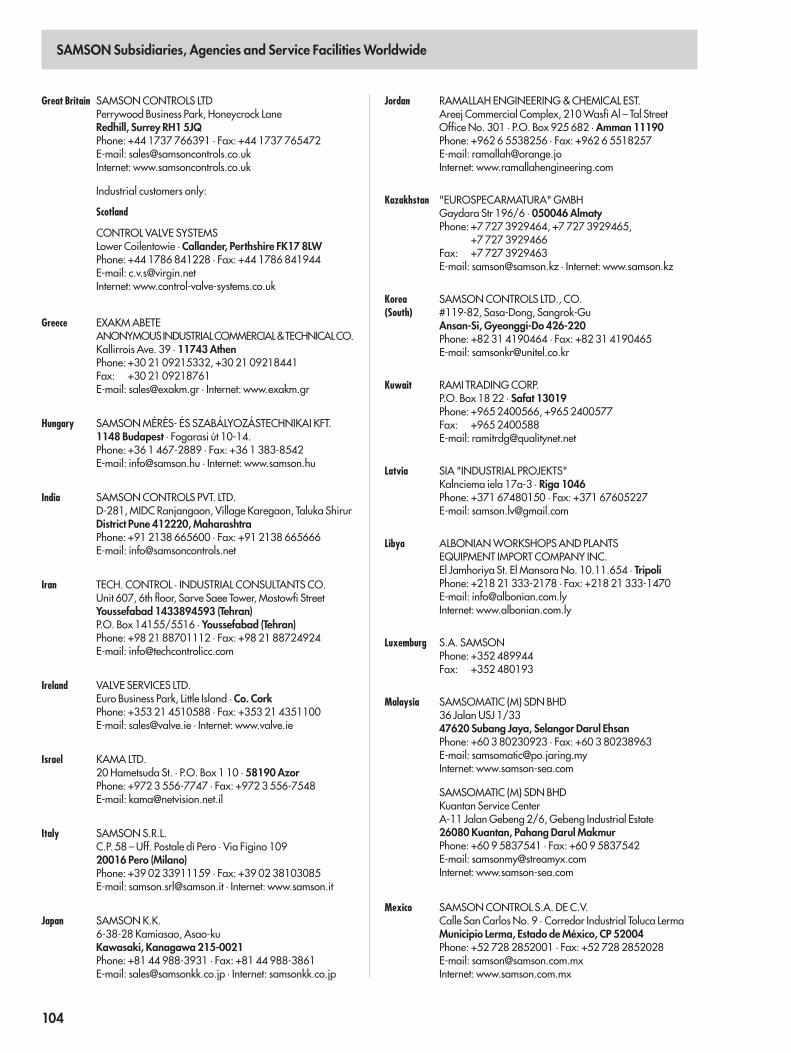
SAMSON Subsidiaries, Agencies and Service Facilities Worldwide
Great Britain SAMSON CONTROLS LTDPerrywood Business Park, Honeycrock LaneRedhill, Surrey RH1 5JQPhone: +44 1737 766391 · Fax: +44 1737 765472E-mail: [email protected]: www.samsoncontrols.co.uk
Industrial customers only:
Scotland
CONTROL VALVE SYSTEMSLower Coilentowie · Callander, Perthshire FK17 8LWPhone: +44 1786 841228 · Fax: +44 1786 841944E-mail: [email protected]: www.control-valve-systems.co.uk
Greece EXAKM ABETEANONYMOUSINDUSTRIALCOMMERCIAL&TECHNICALCO.Kallirrois Ave. 39 · 11743 AthenPhone: +30 21 09215332, +30 21 09218441Fax: +30 21 09218761E-mail: [email protected] · Internet: www.exakm.gr
Hungary SAMSON MÉRÉS- ÉS SZABÁLYOZÁSTECHNIKAI KFT.1148 Budapest · Fogarasi út 10-14.Phone: +36 1 467-2889 · Fax: +36 1 383-8542E-mail: [email protected] · Internet: www.samson.hu
India SAMSON CONTROLS PVT. LTD.D-281, MIDC Ranjangaon, Village Karegaon, Taluka ShirurDistrict Pune 412220, MaharashtraPhone: +91 2138 665600 · Fax: +91 2138 665666E-mail: [email protected]
Iran TECH. CONTROL · INDUSTRIAL CONSULTANTS CO.Unit 607, 6th floor, Sarve Saee Tower, Mostowfi StreetYoussefabad 1433894593 (Tehran)P.O. Box 14155/5516 · Youssefabad (Tehran)Phone: +98 21 88701112 · Fax: +98 21 88724924E-mail: [email protected]
Ireland VALVE SERVICES LTD.Euro Business Park, Little Island · Co. CorkPhone: +353 21 4510588 · Fax: +353 21 4351100E-mail: [email protected] · Internet: www.valve.ie
Israel KAMA LTD.20 Hametsuda St. · P.O. Box 1 10 · 58190 AzorPhone: +972 3 556-7747 · Fax: +972 3 556-7548E-mail: [email protected]
Italy SAMSON S.R.L.C.P. 58 – Uff. Postale di Pero · Via Figino 10920016 Pero (Milano)Phone: +39 02 33911159 · Fax: +39 02 38103085E-mail: [email protected] · Internet: www.samson.it
Japan SAMSON K.K.6-38-28 Kamiasao, Asao-kuKawasaki, Kanagawa 215-0021Phone: +81 44 988-3931 · Fax: +81 44 988-3861E-mail: [email protected] · Internet: samsonkk.co.jp
Jordan RAMALLAH ENGINEERING & CHEMICAL EST.Areej Commercial Complex, 210 Wasfi Al – Tal StreetOffice No. 301 · P.O. Box 925 682 · Amman 11190Phone: +962 6 5538256 · Fax: +962 6 5518257E-mail: [email protected]: www.ramallahengineering.com
Kazakhstan "EUROSPECARMATURA" GMBHGaydara Str 196/6 · 050046 AlmatyPhone: +7 727 3929464, +7 727 3929465,
+7 727 3929466Fax: +7 727 3929463E-mail: [email protected] · Internet: www.samson.kz
Korea(South)
SAMSON CONTROLS LTD., CO.#119-82, Sasa-Dong, Sangrok-GuAnsan-Si, Gyeonggi-Do 426-220Phone: +82 31 4190464 · Fax: +82 31 4190465E-mail: [email protected]
Kuwait RAMI TRADING CORP.P.O. Box 18 22 · Safat 13019Phone: +965 2400566, +965 2400577Fax: +965 2400588E-mail: [email protected]
Latvia SIA "INDUSTRIAL PROJEKTS"Kalnciema iela 17a-3 · Riga 1046Phone: +371 67480150 · Fax: +371 67605227E-mail: [email protected]
Libya ALBONIAN WORKSHOPS AND PLANTSEQUIPMENT IMPORT COMPANY INC.El Jamhoriya St. El Mansora No. 10.11.654 · TripoliPhone: +218 21 333-2178 · Fax: +218 21 333-1470E-mail: [email protected]: www.albonian.com.ly
Luxemburg S.A. SAMSONPhone: +352 489944Fax: +352 480193
Malaysia SAMSOMATIC (M) SDN BHD36 Jalan USJ 1/3347620 Subang Jaya, Selangor Darul EhsanPhone: +60 3 80230923 · Fax: +60 3 80238963E-mail: [email protected]: www.samson-sea.com
SAMSOMATIC (M) SDN BHDKuantan Service CenterA-11 Jalan Gebeng 2/6, Gebeng Industrial Estate26080 Kuantan, Pahang Darul MakmurPhone: +60 9 5837541 · Fax: +60 9 5837542E-mail: [email protected]: www.samson-sea.com
Mexico SAMSON CONTROL S.A. DE C.V.Calle San Carlos No. 9 · Corredor Industrial Toluca LermaMunicipio Lerma, Estado de México, CP 52004Phone: +52 728 2852001 · Fax: +52 728 2852028E-mail: [email protected]: www.samson.com.mx
104
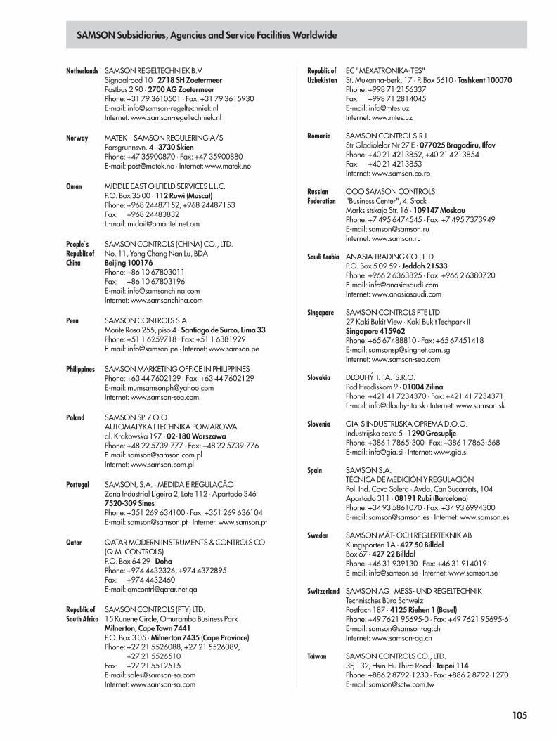
SAMSON Subsidiaries, Agencies and Service Facilities Worldwide
Netherlands SAMSON REGELTECHNIEK B.V.Signaalrood 10 · 2718 SH ZoetermeerPostbus 2 90 · 2700 AG ZoetermeerPhone: +31 79 3610501 · Fax: +31 79 3615930E-mail: [email protected]: www.samson-regeltechniek.nl
Norway MATEK – SAMSON REGULERING A/SPorsgrunnsvn. 4 · 3730 SkienPhone: +47 35900870 · Fax: +47 35900880E-mail: [email protected] · Internet: www.matek.no
Oman MIDDLE EAST OILFIELD SERVICES L.L.C.P.O. Box 35 00 · 112 Ruwi (Muscat)Phone: +968 24487152, +968 24487153Fax: +968 24483832E-mail: [email protected]
People`sRepublic ofChina
SAMSON CONTROLS (CHINA) CO., LTD.No. 11, Yong Chang Nan Lu, BDABeijing 100176Phone: +86 10 67803011Fax: +86 10 67803196E-mail: [email protected]: www.samsonchina.com
Peru SAMSON CONTROLS S.A.Monte Rosa 255, piso 4 · Santiago de Surco, Lima 33Phone: +51 1 6259718 · Fax: +51 1 6381929E-mail: [email protected] · Internet: www.samson.pe
Philippines SAMSON MARKETING OFFICE IN PHILIPPINESPhone: +63 44 7602129 · Fax: +63 44 7602129E-mail: [email protected]: www.samson-sea.com
Poland SAMSON SP. Z O.O.AUTOMATYKA I TECHNIKA POMIAROWAal. Krakowska 197 · 02-180 WarszawaPhone: +48 22 5739-777 · Fax: +48 22 5739-776E-mail: [email protected]: www.samson.com.pl
Portugal SAMSON, S.A. · MEDIDA E REGULAÇÃOZona Industrial Ligeira 2, Lote 112 · Apartado 3467520-309 SinesPhone: +351 269 634100 · Fax: +351 269 636104E-mail: [email protected] · Internet: www.samson.pt
Qatar QATAR MODERN INSTRUMENTS & CONTROLS CO.(Q.M. CONTROLS)P.O. Box 64 29 · DohaPhone: +974 4432326, +974 4372895Fax: +974 4432460E-mail: [email protected]
Republic ofSouth Africa
SAMSON CONTROLS (PTY) LTD.15 Kunene Circle, Omuramba Business ParkMilnerton, Cape Town 7441P.O. Box 3 05 · Milnerton 7435 (Cape Province)Phone: +27 21 5526088, +27 21 5526089,
+27 21 5526510Fax: +27 21 5512515E-mail: [email protected]: www.samson-sa.com
Republic ofUzbekistan
EC "MEXATRONIKA-TES"St. Mukanna-berk, 17 · P. Box 5610 · Tashkent 100070Phone: +998 71 2156337Fax: +998 71 2814045E-mail: [email protected]: www.mtes.uz
Romania SAMSON CONTROL S.R.L.Str Gladiolelor Nr 27 E · 077025 Bragadiru, IlfovPhone: +40 21 4213852, +40 21 4213854Fax: +40 21 4213853Internet: www.samson.co.ro
RussianFederation
OOO SAMSON CONTROLS"Business Center", 4. StockMarksistskaja Str. 16 · 109147 MoskauPhone: +7 495 6474545 · Fax: +7 495 7373949E-mail: [email protected]: www.samson.ru
Saudi Arabia ANASIA TRADING CO., LTD.P.O. Box 5 09 59 · Jeddah 21533Phone: +966 2 6363825 · Fax: +966 2 6380720E-mail: [email protected]: www.anasiasaudi.com
Singapore SAMSON CONTROLS PTE LTD27 Kaki Bukit View · Kaki Bukit Techpark IISingapore 415962Phone: +65 67488810 · Fax: +65 67451418E-mail: [email protected]: www.samson-sea.com
Slovakia DLOUHÝ I.T.A. S.R.O.Pod Hradiskom 9 · 01004 ZilinaPhone: +421 41 7234370 · Fax: +421 41 7234371E-mail: [email protected] · Internet: www.samson.sk
Slovenia GIA-S INDUSTRIJSKA OPREMA D.O.O.Industrijska cesta 5 · 1290 GrosupljePhone: +386 1 7865-300 · Fax: +386 1 7863-568E-mail: [email protected] · Internet: www.gia.si
Spain SAMSON S.A.TÉCNICA DE MEDICIÓN Y REGULACIÓNPol. Ind. Cova Solera · Avda. Can Sucarrats, 104Apartado 311 · 08191 Rubi (Barcelona)Phone: +34 93 5861070 · Fax: +34 93 6994300E-mail: [email protected] · Internet: www.samson.es
Sweden SAMSON MÄT- OCH REGLERTEKNIK ABKungsporten 1A · 427 50 BilldalBox 67 · 427 22 BilldalPhone: +46 31 939130 · Fax: +46 31 914019E-mail: [email protected] · Internet: www.samson.se
Switzerland SAMSON AG · MESS- UND REGELTECHNIKTechnisches Büro SchweizPostfach 187 · 4125 Riehen 1 (Basel)Phone: +49 7621 95695-0 · Fax: +49 7621 95695-6E-mail: [email protected]: www.samson-ag.ch
Taiwan SAMSON CONTROLS CO., LTD.3F, 132, Hsin-Hu Third Road · Taipei 114Phone: +886 2 8792-1230 · Fax: +886 2 8792-1270E-mail: [email protected]
105
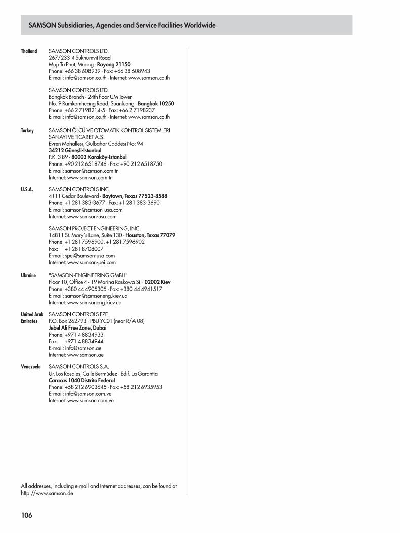
SAMSON Subsidiaries, Agencies and Service Facilities Worldwide
Thailand SAMSON CONTROLS LTD.267/233-4 Sukhumvit RoadMap Ta Phut, Muang · Rayong 21150Phone: +66 38 608939 · Fax: +66 38 608943E-mail: [email protected] · Internet: www.samson.co.th
SAMSON CONTROLS LTD.Bangkok Branch · 24th floor UM TowerNo. 9 Ramkamheang Road, Suanluang · Bangkok 10250Phone: +66 2 7198214-5 · Fax: +66 2 7198237E-mail: [email protected] · Internet: www.samson.co.th
Turkey SAMSON ÖLÇÜ VE OTOMATIK KONTROL SISTEMLERISANAYI VE TICARET A.S
´.
Evren Mahallesi, Gülbahar Caddesi No: 9434212 Günes
´li-Istanbul
P.K. 3 89 · 80003 Karaköy-IstanbulPhone: +90 212 6518746 · Fax: +90 212 6518750E-mail: [email protected]: www.samson.com.tr
U.S.A. SAMSON CONTROLS INC.4111 Cedar Boulevard · Baytown, Texas 77523-8588Phone: +1 281 383-3677 · Fax: +1 281 383-3690E-mail: [email protected]: www.samson-usa.com
SAMSON PROJECT ENGINEERING, INC.14811 St. Mary´s Lane, Suite 130 · Houston, Texas 77079Phone: +1 281 7596900, +1 281 7596902Fax: +1 281 8708007E-mail: [email protected]: www.samson-pei.com
Ukraine "SAMSON-ENGINEERING GMBH"Floor 10, Office 4 · 19 Marina Raskowa St · 02002 KievPhone: +380 44 4905305 · Fax: +380 44 4941517E-mail: [email protected]: www.samsoneng.kiev.ua
United ArabEmirates
SAMSON CONTROLS FZEP.O. Box 262793 · PBU YC01 (near R/A 08)Jebel Ali Free Zone, DubaiPhone: +971 4 8834933Fax: +971 4 8834944E-mail: [email protected]: www.samson.ae
Venezuela SAMSON CONTROLS S.A.Ur. Los Rosales, Calle Bermúdez · Edif. La GarantíaCaracas 1040 Distrito FederalPhone: +58 212 6903645 · Fax: +58 212 6935953E-mail: [email protected]: www.samson.com.ve
All addresses, including e-mail and Internet addresses, can be found athttp://www.samson.de
106

______________________________________________________________________________________________________________________________
______________________________________________________________________________________________________________________________
______________________________________________________________________________________________________________________________
______________________________________________________________________________________________________________________________
______________________________________________________________________________________________________________________________
______________________________________________________________________________________________________________________________
______________________________________________________________________________________________________________________________
______________________________________________________________________________________________________________________________
______________________________________________________________________________________________________________________________
______________________________________________________________________________________________________________________________
______________________________________________________________________________________________________________________________
______________________________________________________________________________________________________________________________
______________________________________________________________________________________________________________________________
______________________________________________________________________________________________________________________________
______________________________________________________________________________________________________________________________
______________________________________________________________________________________________________________________________
______________________________________________________________________________________________________________________________
______________________________________________________________________________________________________________________________
______________________________________________________________________________________________________________________________
______________________________________________________________________________________________________________________________
______________________________________________________________________________________________________________________________
______________________________________________________________________________________________________________________________
______________________________________________________________________________________________________________________________
______________________________________________________________________________________________________________________________
______________________________________________________________________________________________________________________________
______________________________________________________________________________________________________________________________
______________________________________________________________________________________________________________________________
______________________________________________________________________________________________________________________________
______________________________________________________________________________________________________________________________
Notes
107

______________________________________________________________________________________________________________________________
______________________________________________________________________________________________________________________________
______________________________________________________________________________________________________________________________
______________________________________________________________________________________________________________________________
______________________________________________________________________________________________________________________________
______________________________________________________________________________________________________________________________
______________________________________________________________________________________________________________________________
______________________________________________________________________________________________________________________________
______________________________________________________________________________________________________________________________
______________________________________________________________________________________________________________________________
______________________________________________________________________________________________________________________________
______________________________________________________________________________________________________________________________
______________________________________________________________________________________________________________________________
______________________________________________________________________________________________________________________________
______________________________________________________________________________________________________________________________
______________________________________________________________________________________________________________________________
______________________________________________________________________________________________________________________________
______________________________________________________________________________________________________________________________
______________________________________________________________________________________________________________________________
______________________________________________________________________________________________________________________________
______________________________________________________________________________________________________________________________
______________________________________________________________________________________________________________________________
______________________________________________________________________________________________________________________________
______________________________________________________________________________________________________________________________
______________________________________________________________________________________________________________________________
______________________________________________________________________________________________________________________________
______________________________________________________________________________________________________________________________
______________________________________________________________________________________________________________________________
______________________________________________________________________________________________________________________________
Notes
108
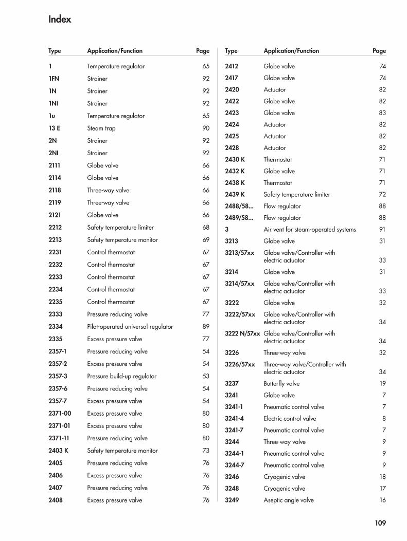
1 Temperature regulator 65
1FN Strainer 92
1N Strainer 92
1NI Strainer 92
1u Temperature regulator 65
13 E Steam trap 90
2N Strainer 92
2NI Strainer 92
2111 Globe valve 66
2114 Globe valve 66
2118 Three-way valve 66
2119 Three-way valve 66
2121 Globe valve 66
2212 Safety temperature limiter 68
2213 Safety temperature monitor 69
2231 Control thermostat 67
2232 Control thermostat 67
2233 Control thermostat 67
2234 Control thermostat 67
2235 Control thermostat 67
2333 Pressure reducing valve 77
2334 Pilot-operated universal regulator 89
2335 Excess pressure valve 77
2357-1 Pressure reducing valve 54
2357-2 Excess pressure valve 54
2357-3 Pressure build-up regulator 53
2357-6 Pressure reducing valve 54
2357-7 Excess pressure valve 54
2371-00 Excess pressure valve 80
2371-01 Excess pressure valve 80
2371-11 Pressure reducing valve 80
2403 K Safety temperature monitor 73
2405 Pressure reducing valve 76
2406 Excess pressure valve 76
2407 Pressure reducing valve 76
2408 Excess pressure valve 76
2412 Globe valve 74
2417 Globe valve 74
2420 Actuator 82
2422 Globe valve 82
2423 Globe valve 83
2424 Actuator 82
2425 Actuator 82
2428 Actuator 82
2430 K Thermostat 71
2432 K Globe valve 71
2438 K Thermostat 71
2439 K Safety temperature limiter 72
2488/58... Flow regulator 88
2489/58... Flow regulator 88
3 Air vent for steam-operated systems 91
3213 Globe valve 31
3213/57xx Globe valve/Controller with electric actuator 33
3214 Globe valve 31
3214/57xx Globe valve/Controller with electric actuator 33
3222 Globe valve 32
3222/57xx Globe valve/Controller with electric actuator 34
3222 N/57xx Globe valve/Controller with electric actuator 34
3226 Three-way valve 32
3226/57xx Three-way valve/Controller with electric actuator 34
3237 Butterfly valve 19
3241 Globe valve 7
3241-1 Pneumatic control valve 7
3241-4 Electric control valve 8
3241-7 Pneumatic control valve 7
3244 Three-way valve 9
3244-1 Pneumatic control valve 9
3244-7 Pneumatic control valve 9
3246 Cryogenic valve 18
3248 Cryogenic valve 17
3249 Aseptic angle valve 16
Type Application/Function Page Type Application/Function Page
Index
109
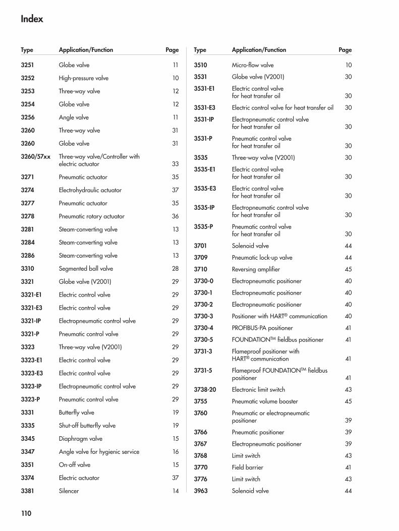
3251 Globe valve 11
3252 High-pressure valve 10
3253 Three-way valve 12
3254 Globe valve 12
3256 Angle valve 11
3260 Three-way valve 31
3260 Globe valve 31
3260/57xx Three-way valve/Controller with electric actuator 33
3271 Pneumatic actuator 35
3274 Electrohydraulic actuator 37
3277 Pneumatic actuator 35
3278 Pneumatic rotary actuator 36
3281 Steam-converting valve 13
3284 Steam-converting valve 13
3286 Steam-converting valve 13
3310 Segmented ball valve 28
3321 Globe valve (V2001) 29
3321-E1 Electric control valve 29
3321-E3 Electric control valve 29
3321-IP Electropneumatic control valve 29
3321-P Pneumatic control valve 29
3323 Three-way valve (V2001) 29
3323-E1 Electric control valve 29
3323-E3 Electric control valve 29
3323-IP Electropneumatic control valve 29
3323-P Pneumatic control valve 29
3331 Butterfly valve 19
3335 Shut-off butterfly valve 19
3345 Diaphragm valve 15
3347 Angle valve for hygienic service 16
3351 On-off valve 15
3374 Electric actuator 37
3381 Silencer 14
3510 Micro-flow valve 10
3531 Globe valve (V2001) 30
3531-E1 Electric control valve for heat transfer oil 30
3531-E3 Electric control valve for heat transfer oil 30
3531-IP Electropneumatic control valve for heat transfer oil 30
3531-P Pneumatic control valve for heat transfer oil 30
3535 Three-way valve (V2001) 30
3535-E1 Electric control valve for heat transfer oil 30
3535-E3 Electric control valve for heat transfer oil 30
3535-IP Electropneumatic control valve for heat transfer oil 30
3535-P Pneumatic control valve for heat transfer oil 30
3701 Solenoid valve 44
3709 Pneumatic lock-up valve 44
3710 Reversing amplifier 45
3730-0 Electropneumatic positioner 40
3730-1 Electropneumatic positioner 40
3730-2 Electropneumatic positioner 40
3730-3 Positioner with HART® communication 40
3730-4 PROFIBUS-PA positioner 41
3730-5 FOUNDATIONTM fieldbus positioner 41
3731-3 Flameproof positioner with HART® communication 41
3731-5 Flameproof FOUNDATIONTM fieldbus positioner 41
3738-20 Electronic limit switch 43
3755 Pneumatic volume booster 45
3760 Pneumatic or electropneumatic positioner 39
3766 Pneumatic positioner 39
3767 Electropneumatic positioner 39
3768 Limit switch 43
3770 Field barrier 41
3776 Limit switch 43
3963 Solenoid valve 44
Type Application/Function Page Type Application/Function Page
Index
110
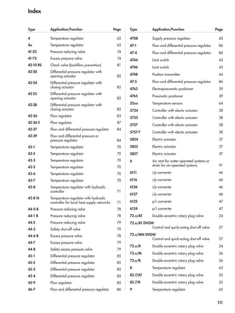
4 Temperature regulator 65
4u Temperature regulator 65
41-23 Pressure reducing valve 74
41-73 Excess pressure valve 74
42-10 RS Check valve (backflow prevention) 81
42-20 Differential pressure regulator with opening actuator 82
42-24 Differential pressure regulator with closing actuator 82
42-25 Differential pressure regulator with opening actuator 82
42-28 Differential pressure regulator with closing actuator 82
42-36 Flow regulator 83
42-36 E Flow regulator 87
42-37 Flow and differential pressure regulator 84
42-39 Flow and differential pressure or pressure regulator 84
43-1 Temperature regulator 70
43-2 Temperature regulator 70
43-3 Temperature regulator 70
43-5 Temperature regulator 70
43-6 Temperature regulator 70
43-7 Temperature regulator 70
43-8 Temperature regulator with hydraulic controller 71
43-8 N Temperature regulator with hydraulic controller for local heat supply networks 71
44-0 B Pressure reducing valve 78
44-1 B Pressure reducing valve 78
44-2 Pressure reducing valve 79
44-3 Safety shut-off valve 79
44-6 B Excess pressure valve 78
44-7 Excess pressure valve 79
44-8 Safety excess pressure valve 79
45-1 Differential pressure regulator 85
45-2 Differential pressure regulator 85
45-3 Differential pressure regulator 85
45-4 Differential pressure regulator 85
45-9 Flow regulator 85
46-7 Flow and differential pressure regulator 86
4708 Supply pressure regulator 45
47-1 Flow and differential pressure regulator 86
47-4 Flow and differential pressure regulator 86
4744 Limit switch 43
4746 Limit switch 43
4748 Position transmitter 44
47-5 Flow and differential pressure regulator 86
4763 Electropneumatic positioner 39
4765 Pneumatic positioner 39
52xx Temperature sensors 64
5724 Controller with electic actuator 38
5725 Controller with electic actuator 38
5757 Controller with electic actuator 38
5757-7 Controller with electic actuator 38
5824 Electric actuator 37
5825 Electric actuator 37
5857 Electric actuator 37
6 Air vent for water-operated systems or drain for air-operated systems 91
6111 i/p converter 46
6116 i/p converter 46
6126 i/p converter 46
6127 i/p converter 46
6132 p/i converter 47
6134 p/i converter 47
72.x/AT Double eccentric rotary plug valve 24
72.x/AT DVGW Control and quick-acting shut-off valve 27
72.x/MN DVGW Control and quick-acting shut-off valve 27
72.x/R Double eccentric rotary plug valve 24
73.x/M Double eccentric rotary plug valve 26
73.x/R Double eccentric rotary plug valve 26
8 Temperature regulator 65
82.7/AT Double eccentric rotary plug valve 25
82.7/R Double eccentric rotary plug valve 25
9 Temperature regulator 65
Type Application/Function Page Type Application/Function Page
Index
111
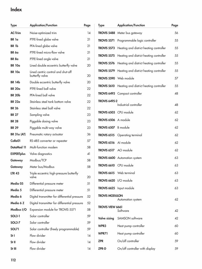
AC-Trim Noise-optimized trim 14
BR 1a PTFE-lined globe valve 21
BR 1b PFA-lined globe valve 21
BR 6a PTFE-lined micro-flow valve 21
BR 8a PTFE-lined angle valve 21
BR 10a Lined double eccentric butterfly valve 20
BR 10e Lined centric control and shut-off butterfly valve 20
BR 14b Double eccentric butterfly valve 20
BR 20a PTFE-lined ball valve 22
BR 20b PFA-lined ball valve 22
BR 22a Stainless steel tank bottom valve 22
BR 26 Stainless steel ball valve 22
BR 27 Sampling valve 23
BR 28 Piggable dosing valve 23
BR 29 Piggable multi-way valve 23
BR 31a (AT) Pneumatic rotary actuator 36
CoRe01 RS-485 converter or repeater 57
DataMod 11 Multi-function modem 58
EXPERTplus Valve diagnostics 41
Gateway Modbus/TCP 58
Gateway Meter bus/Modbus 58
LTR 43 Triple eccentric high-pressure butterfly valve 20
Media 05 Differential pressure meter 51
Media 5 Differential pressure meter 51
Media 6 Digital transmitter for differential pressure 52
Media 6 Z Digital transmitter for differential pressure 52
Modbus I/O Expansion module for TROVIS 5571 58
SOL3-1 Solar controller 59
SOL3-7 Solar controller 59
SOL71 Solar controller (freely programmable) 59
St I Flow divider 14
St II Flow divider 14
St III Flow divider 14
TROVIS 5488 Meter bus gateway 56
TROVIS 5571 Programmable logic controller 55
TROVIS 5573 Heating and district heating controller 55
TROVIS 5575 Heating and district heating controller 55
TROVIS 5576 Heating and district heating controller 55
TROVIS 5579 Heating and district heating controller 55
TROVIS 5590 Web module 57
TROVIS 5610 Heating and district heating controller 55
TROVIS 6493 Compact controller 48
TROVIS 6495-2 Industrial controller 48
TROVIS 6503 CPU module 62
TROVIS 6506 A module 62
TROVIS 6507 B module 62
TROVIS 6515 Operating terminal 62
TROVIS 6516 AI module 62
TROVIS 6517 AO module 62
TROVIS 6600 Automation system 63
TROVIS 6610 CPU module 63
TROVIS 6615 Web terminal 63
TROVIS 6620 I/O module 63
TROVIS 6625 Input module 63
TROVIS MODULON Automation system 62
TROVIS VIEW 6661 Software 42
Valve sizing SAMSON software 42
WPR3 Heat pump controller 60
WPR71 Heat pump controller 60
ZPR On/off controller 59
ZPR-D On/off controller with display 59
Type Application/Function Page Type Application/Function Page
Index
112


Products
Catalog
2011
-06
WS
· K 2
0 EN
SAM
SON
Prod
ucts
SAMSON AG · MESS- UND REGELTECHNIK Weismüllerstraße 3 · 60314 Frankfurt am Main · GermanyPhone: +49 69 4009-0 · Fax: +49 69 4009-1507 E-mail: [email protected] · Internet: www.samson.de · www.samsongroup.de


![Samson. HWV 57 - accueil (data.bnf.fr) · Samson. - Awake the trumpet's lofty sound. - [6] (1995) Samson. - Awake the trumpet's lofty sound. - [6] (1995) Samson. - Awake the trumpet's](https://static.fdocuments.net/doc/165x107/600665197a8f42597414c65e/samson-hwv-57-accueil-databnffr-samson-awake-the-trumpets-lofty-sound.jpg)
