S&S® Cycle
98
S&S® Cycle ProTune II User Manual
Transcript of S&S® Cycle

S&S® Cycle
ProTune II
User Manual


3Contents
3
2014 S&S Cycle® Inc.
Table of Contents
Foreword 0
Installation 7
................................................................................................................................... 71 System Requirements
................................................................................................................................... 72 Installation
................................................................................................................................... 93 Manual USB Device Driver Installation
.......................................................................................................................................................... 10Windows® XP
.......................................................................................................................................................... 11Windows® Vista™, 7 and 8
................................................................................................................................... 124 Removal
Introduction 12
................................................................................................................................... 121 Getting Started
................................................................................................................................... 142 Using Help
................................................................................................................................... 153 Basic and Advanced User Levels
................................................................................................................................... 154 Connecting the ECM
................................................................................................................................... 155 Connecting the PC to Serial ECMs
................................................................................................................................... 166 Connecting the PC to USB ECMs
................................................................................................................................... 177 The Main Window in Basic Mode
................................................................................................................................... 198 The Main Window in Advanced Mode
Menu Functions 21
................................................................................................................................... 211 Using Menus
................................................................................................................................... 212 Tool Bar
................................................................................................................................... 223 File Menu
.......................................................................................................................................................... 22Send All Data to ECM
.......................................................................................................................................................... 24Load All Data to Computer
.......................................................................................................................................................... 24Exit
................................................................................................................................... 254 Edit Menu
.......................................................................................................................................................... 25Undo
.......................................................................................................................................................... 25Copy
.......................................................................................................................................................... 25Paste
.......................................................................................................................................................... 26Blend (Interpolate) Selected Area
.......................................................................................................................................................... 26Average Selected Area
.......................................................................................................................................................... 26Tag / Untag Cells
.......................................................................................................................................................... 27Clear All Markers
.......................................................................................................................................................... 27Cycle Grid/Graph Position
.......................................................................................................................................................... 28Cycle Grid Size
.......................................................................................................................................................... 28Cycle Graph-Line Resolution
.......................................................................................................................................................... 28Switch On/Off Map Cursor Pop-up
.......................................................................................................................................................... 29Live-Tune Mode On/Off
.......................................................................................................................................................... 29Switch On/Off Auto-Tagging in LiveTune
.......................................................................................................................................................... 30Track Live-Tune Cursor
.......................................................................................................................................................... 30Snap To Live-Tune Cursor

S&S Cycle® ProTune 24
2014 S&S Cycle® Inc.
.......................................................................................................................................................... 303D Graph Settings
................................................................................................................................... 315 View Menu
.......................................................................................................................................................... 31ECM Basic Setup
.......................................................................................................................................................... 33Diagnostic Trouble Codes
.......................................................................................................................................................... 34ECM Gauges
.......................................................................................................................................................... 35Fuel Injection Base Table
.......................................................................................................................................................... 35Ignition Timing Base Table
.......................................................................................................................................................... 35Front Cylinder Adjustment Table
.......................................................................................................................................................... 36Rear Cylinder Adjustment Table
.......................................................................................................................................................... 36Acceleration Fuel Settings
.......................................................................................................................................................... 37Closed-Loop Control Settings
.......................................................................................................................................................... 38Knock Control Settings
.......................................................................................................................................................... 38Engine Temperature Ignition Compensation
.......................................................................................................................................................... 39Air Temperature Ignition Compensation
.......................................................................................................................................................... 40Engine Temperature Fuel Compensation
.......................................................................................................................................................... 40Air Temperature Fuel Compensation
.......................................................................................................................................................... 41Engine Temperature Start Map
.......................................................................................................................................................... 42Stepper Motor Orientation Setting
.......................................................................................................................................................... 42Stepper Pre-Start Position Map
.......................................................................................................................................................... 43Stepper Position with Temperature Map
.......................................................................................................................................................... 44Target Idle Speed Setting
.......................................................................................................................................................... 45Stepper Position Fuel Compensation
.......................................................................................................................................................... 45Front Cylinder Adaptive Map
.......................................................................................................................................................... 46Rear Cylinder Adaptive Map
.......................................................................................................................................................... 46Target Closed-Loop Fuel Map
.......................................................................................................................................................... 47Adaptive Ignition Map
.......................................................................................................................................................... 47Current Data Source menu
.......................................................................................................................................................... 48Comment Field
.......................................................................................................................................................... 48ECM Information
......................................................................................................................................................... 50ECM
......................................................................................................................................................... 50Stats Overview
......................................................................................................................................................... 51Engine Use
......................................................................................................................................................... 51Peaks
......................................................................................................................................................... 52Last Trip Peaks
......................................................................................................................................................... 53Rev Limiting
................................................................................................................................... 546 Options Menu
.......................................................................................................................................................... 54Preferences
.......................................................................................................................................................... 54Select User Level
.......................................................................................................................................................... 55Serial Port Settings
.......................................................................................................................................................... 56Download Code to ECM
.......................................................................................................................................................... 57Download Tune-File TO ECM
.......................................................................................................................................................... 58Upload Tune-File FROM ECM
.......................................................................................................................................................... 59Open Table from
.......................................................................................................................................................... 60Save Table
.......................................................................................................................................................... 60Save Table To
.......................................................................................................................................................... 61Copy Calibration File
.......................................................................................................................................................... 61Test Outputs
.......................................................................................................................................................... 63Cylinder Trim Adaptive Map Merge
.......................................................................................................................................................... 63Main Fuel Adaptive Map Merge
.......................................................................................................................................................... 64Reset Adaptive Maps
.......................................................................................................................................................... 64Clear Historic Diagnostic Trouble Codes
................................................................................................................................... 657 Help Menu
.......................................................................................................................................................... 65Help Topics

5Contents
5
2014 S&S Cycle® Inc.
.......................................................................................................................................................... 65About ProTune II
The Fuel and Ignition Systems 65
................................................................................................................................... 651 The Fuel Injection System
................................................................................................................................... 662 The Ignition Timing System
Tuning in Basic Mode 67
................................................................................................................................... 671 Viewing and Tuning Tables
................................................................................................................................... 702 Live-Tune in Basic Mode
Tuning in Advanced Mode 71
................................................................................................................................... 711 Using The Spreadsheet
.......................................................................................................................................................... 71Moving the Cursor Position
.......................................................................................................................................................... 72Selecting an Area of the Table
.......................................................................................................................................................... 72Editing Table Values
.......................................................................................................................................................... 73Using Math Functions to Edit Table Values
.......................................................................................................................................................... 73Tag/Untag Cells
.......................................................................................................................................................... 74Grid Size of the Spreadsheet
................................................................................................................................... 742 Using the 3D Graph
................................................................................................................................... 753 Spreadsheet and Graph Layout
................................................................................................................................... 754 Live-Tune in Advanced Mode
.......................................................................................................................................................... 76Activating Live-Tune Mode
.......................................................................................................................................................... 76Tuning in Live-Tune Mode
.......................................................................................................................................................... 77Deactivating Live-Tune Mode
Gauges and Realtime Data 78
................................................................................................................................... 781 Using the Gauges Window
.......................................................................................................................................................... 79To Add a Dial or Text Gauge
.......................................................................................................................................................... 79To Remove a Gauge
.......................................................................................................................................................... 80Always On Top setting
.......................................................................................................................................................... 80Opening\Saving the Gauges Window Layout
................................................................................................................................... 802 The Engine Data Area
Advanced Calibration Tables 81
................................................................................................................................... 811 Viewing and Editing Advanced Tables
................................................................................................................................... 822 Temperature Compensation Tables
................................................................................................................................... 823 Engine Temperature Start Map
................................................................................................................................... 824 Stepper Motor Tables (Idle Speed Control)
Closed-Loop Fuel Control 83
................................................................................................................................... 831 The Closed-Loop Fuel Control System
................................................................................................................................... 842 Closed-Loop Setup in Basic Mode
................................................................................................................................... 853 Closed-Loop Setup in Advanced Mode
................................................................................................................................... 864 Setting the Target Air-Fuel Mixture
................................................................................................................................... 875 Using the Adaptive Maps
S&S Cycle® ProTune 26
2014 S&S Cycle® Inc.
Knock (Adaptive Ignition) Control 88
................................................................................................................................... 881 The Knock Control System
Diagnostics 88
................................................................................................................................... 881 Frequently Asked Questions
................................................................................................................................... 902 Troubleshooting USB Driver Problems
.......................................................................................................................................................... 90Windows® XP
.......................................................................................................................................................... 91Windows® Vista™, 7 and 8
................................................................................................................................... 913 Check Engine Lamp Diagnostics
................................................................................................................................... 924 Speedometer Diagnostics
................................................................................................................................... 935 Check Engine Lamp - Fault Codes
Glossary 94
Footnote 95
Index 97

Installation 7
2014 S&S Cycle® Inc.
1 Installation
1.1 System Requirements
You must have the following minimum PCspecification to install and run ProTune 2:
· Microsoft® Windows® XP Service Pack 2or later, Microsoft® Windows® Vista™,Microsoft® Windows® 7, Microsoft®Windows® 8 or later operating system.Windows® RT (tablet) is not supported.
· 1.0 Ghz or faster processor. Intel® Core™Duo or faster/equivalent recommended.
· 128Mb System RAM, 256Mb or morerecommended.
· 200Mb of free hard drive space.· A desktop resolution of at least 1024x768
pixels. Higher desktop resolution isrecommended for optimum use.
· A modern graphics system with 3Dacceleration and 64 MB or greater on-board RAM is required.
A 9-Pin serial COM port is required forcommunication with serial based modules(see below).
For USB modules, an available USB port(version 1 or later) is required.
For connection to serial modules:
Your computer's 9-Pin serial port will usuallybe located near the printer port and will looksimilar to the one in this picture:
If your PC does not have a serial port then aUSB-Serial port adapter may be used instead.Before purchasing a USB-Serial adapter, besure it is compatible with your PC's operatingsystem.
For connection to USB modules:
Most PCs have multiple USB ports. Yourcomputer's USB port will look similar to thetwo shown in this picture:
If your PC does not have a USB port then itmay not be sufficiently up-to-date to runProTune 2. Please check the specificationabove. If your PC otherwise matches theminimum specification required for thesoftware, USB add-on cards can bepurchased from computer vendors for bothnotebooks and desktop PCs.
1.2 Installation
To install ProTune 2 for the first time or toupgrade ProTune 2, perform the following:
1. Close all applications, especially any S&S®Cycle programs that are currently running.
2. Insert ProTune 2 installation CD into yourCD or DVD drive. After a few moments thesetup program should appear on yourscreen and you can skip to step 5. If thisdoesn't happen automatically, proceedwith steps 3 and 4.
3. From the Start menu, select Run … orhold the Windows key and press R. Theappearance of your Start menu will varydepending on the version of Windows®that you are using.

S&S Cycle® ProTune 28
2014 S&S Cycle® Inc.
4. In the box marked Open: type D:\setup.exe and press Enter or click OK. MostPCs have the CD-ROM drive letter 'D:'.Replace this with the appropriate letter ifyour CD drive installation is different.
5. The Windows® Installer dialog box willappear and briefly examine your system.
6. The Welcome screen will now appear.Click Next.
7. The Ready To Install screen will nowappear. Click Install.
8. The installer will now install and copy filesto your computer. If a warning messageappears during USB driver installation,click Install/Continue Anyway.

Installation 9
2014 S&S Cycle® Inc.
9. Installation is now complete. Click Finish.
The user files such as calibration files andECM code for this software are located in '[My Documents]\ProTune 2' directory.
When upgrading from a previous version ofProTune 2, calibration files from the previousinstallation of the software will be copied tothe new 'Calibrations\Archive' folder, sothey remain accessible in the new version.
After the installation, the ProTune 2 programicon will appear on your desktop. Double-click this icon to start ProTune 2. You canalso find ProTune 2 in your Programs menuunder the program group 'S&S Cycle'.
1.3 Manual USB Device Driver Installation
Installation of a device driver is requiredwhen you first connect a USB ECM to a PC.This USB driver is installed during theinstallation of ProTune 2. A USB device driveris an item of software which allowsWindows® to communicate with the USBdevice. You do not need a device driver tocommunicate with a serial ECM.
The driver is located on your system whenthe software is installed. If you need toinstall the driver manually, follow theprocedure outlined here.
In order to install the USB device driver,follow the steps below and then follow thesteps appropriate to your version ofWindows. Please be sure to follow theinstructions as closely as possible.
1. Install the ECM using the separateinstallation instructions provided.
2. Close all Windows programs, includingProTune 2.
3. Securely connect a standard USB-A to 5-pin mini-B cable to the mini-USB port onthe case of the ECM.
4. Switch the vehicle ignition key to theignition ON position. Switch the engine killswitch to the RUN position. This will power

S&S Cycle® ProTune 210
2014 S&S Cycle® Inc.
the ECM.
5. Connect the USB cable to an available USBport on your PC.
Now follow the instructions specific to yourversion of Microsoft® Windows:
Windows® XP
Windows® Vista™ & Windows® 7 and 8
1.3.1 Windows® XP
1. A few moments after connecting thepowered ECM, Windows® will detect thepresence of the new device. A smallballoon window in the lower-right cornerof the screen will indicate this. Wait forthe Found New Hardware Wizard toappear.
2. When the Found New HardwareWizard appears, select No, not thistime to skip the Windows Update searchand click Next >.
3. Select Install the softwareautomatically (Recommended) fromthe list of options and click Next >.
4. Windows will now locate the correct driverfile and copy the required files. Wait forthis to complete.
10
11

Installation 11
2014 S&S Cycle® Inc.
5. Depending on your security settings, awarning may appear indicating that thedriver is 'unsigned'. Click ContinueAnyway.
6. The device driver installation is nowcomplete. Click Finish. You can now useProTune 2 to communicate with the USBECM.
1.3.2 Windows® Vista™, 7 and 8
1. A few moments after connecting thepowered ECM, Windows® will detect thepresence of the new device. A smallballoon window in the lower-right cornerof the screen will indicate this. Windows®should automatically install the USB driverand you can skip to step 5. If this doesnot occur, proceed with step 2.
2. Wait for the Found New Hardwaredialog box to appear.
3. When the Found New Hardware dialogbox appears, double-click the Locate andinstall driver software(recommended) option.
4. Depending on your user account settings,a security warning message may appearasking you to confirm the deviceinstallation. Allow the installation tocontinue.
5. Depending on your security settings, themessage shown below may appear. Clickon Install to continue.
6. The device driver installation is nowcomplete. Click Close. You can now useProTune 2 to communicate with the USBECM.

S&S Cycle® ProTune 212
2014 S&S Cycle® Inc.
1.4 Removal
Important Note: When you removeProTune 2, any files that you havemodified or added will be left unalteredon your hard-drive. If you reinstallProTune 2, new files that you havecreated will be left unaltered but filesthat you have modified will beoverwritten with the original copies.
Hint: If you need to copy or backup any datafiles in ProTune 2 version 2.2 or earlier, thesecan be found on your computer in theC:\Program Files\S&S Cycle\ProTune2\Tune-Files folder. If you need to copy orbackup any data files in ProTune 2 version2.3 or later, these can be found on yourcomputer in the [My Documents]\ProTune 2folder. Tune-Files have a .ECC file extensionand Box files have a .BOX file extension.
To remove ProTune 2 from your system, usethe following procedure:
1. Make sure that ProTune 2 is closed.
2. From the Start menu, access theWindows® Control Panel (this may belocated in the Settings menu on someversions of Windows®).
3. For computers earlier than Windows Vista™, select Add/Remove Programs fromthe Control Panel. For Windows Vista™and later, select Uninstall a Programlocated in the Programs section.
4. Highlight ProTune 2 in the list ofprograms displayed. Click Uninstall.
5. ProTune 2 will now uninstall from yoursystem.
2 Introduction
2.1 Getting Started
ProTune 2 is a PC software application thatallows you to setup and tune your S&SCycle® Variable Fuel Injection (VFI) modulefor your performance requirements.Throughout this software and helpdocument, the S&S Cycle® Variable FuelInjection module is referred to as the ECM(Electronic Control Module).
The following terminology is also usedthroughout this software:

Introduction 13
2014 S&S Cycle® Inc.
Calibration (File). This is a complete copy ofall the configuration data inside an ECM,stored as a file on disk. There are two typesof Calibration files, tune-files and BOX files.
BOX File. A type of calibration file thatcontains a complete record of the ECMconfiguration data (a tune-file) paired withan ECM software program file (a .h86 file). S&S Cycle® BOX files have a .box fileextension.
Tune-File. A type of calibration file which onlycontains the ECM configuration data. Use ofTune-Files is for backward compatibility only. S&S Cycle® Tune-Files have a .ecc fileextension.
Demo-Data. ProTune 2 is supplied with ademonstration calibration file which is loadedwhen the software starts. This demonstrationdata allows you to experiment with thesoftware without altering important data.You cannot overwrite information in theDemo Data calibration.
Table. A grid of numbers inside the ECMused to control actuators such as the fuelinjectors and ignition coil.
Tuning. The process of finding the bestvalues to put in a table in order to get theoptimum engine performance for a particularapplication.
ECM Settings. These are data items in theECM used to set global properties of theECM.
For a complete list of terms used in thissoftware, click on the Glossary of Termssection of the Contents.
Below is a description of how to accomplishsome basic tasks with ProTune 2:
WARNING! For serial ECMs, use thesupplied cable to connect the ECM toyour PC. Use of any other cable may
result in damage to the PC.NOTE: You may use a 9-Pin serial extensioncable in conjunction with the supplied cable,but the supplied S&S®cable MUST beconnected to the module.
To view the current trouble-code (fault)status of your ECM:
1. Make sure that your ECM is connected toyour PC. See Connecting the ECM fordetails. WARNING! For serial ECMs,use the supplied cable to connect theECM to your PC. Use of any othercable may result in damage to the PC.
2. Select the DTCs button or DiagnosticTrouble Codes from the View menu.
3. The dialog box will display the current andhistoric trouble-codes for your ECM. See Diagnostic Trouble Codes for moredetails.
To backup the data that is currently inyour ECM, before making modificationsto that data (recommended):
1. Connect your ECM to your PC. See Connecting the ECM for details.WARNING! For serial ECMs, use thesupplied cable to connect the ECM toyour PC. Use of any other cable mayresult in damage to the PC.
2. Go to the File menu and select Load AllData to Computer... Type a newfilename in the File Name dialog box andclick Save. The data will now load fromthe ECM and be stored as a new BOX File.See Load All Data to Computer formore details.
To tune a table from the ECM or aCalibration File:
For a full description on how to tune in BasicMode, familiarize yourself with the The MainWindow in Basic Mode and read theViewing and Tuning Tables section.
15
33
15
24
17
67

S&S Cycle® ProTune 214
2014 S&S Cycle® Inc.
For a full description on how to tune inAdvanced mode, familiarize yourself with the The Main Window in Advanced Mode andread the Using The Spreadsheet section.
1. Connect your ECM to your PC if you wantto tune an ECM table. See Connecting theECM for details. WARNING! Forserial ECMs, use the supplied cable toconnect the ECM to your PC. Use ofany other cable may result in damageto the PC.
2. Select a table by opening the View menuand selecting one of the tables.
3. Select where to load the table from byclicking on the down-arrow in the CurrentData Source box on the top of thescreen. If you just want to experiment,select the Demo Data.
4. Move the cursor around the spreadsheetby using the Up Arrow, Down Arrow, LeftArrow and Right Arrow keys. You can alsoclick on an area of the spreadsheet tomove to that location. Use the scroll barsto view more of the spreadsheet. Hold the Shift-key while using the cursor keys toselect an area of the table.
5. In Advanced mode, enter a new value intothe current cell or selected area by typingthe value and pressing Enter. If the valueis out of range it will be adjusted to thenearest allowed value. In basic mode, usethe tuning and range dials to adjust thevalue of the selected area. You can alsouse the Page Up and Page Down keys toincrement and decrement the values in thetable.
6. Move to another area of the spreadsheetand continue tuning. When you havefinished tuning, select the Save button orOptions menu and select Save TableTo... if you want to save your changes.
2.2 Using Help
This help window is split vertically into twopanes. The right pane displays the currenthelp topic. The left pane is selectablebetween the help document contents, index,search tool, or favorites. By clicking on thevertical bar separating the two panes anddragging it left or right, you can control thesize of the windows.
In the left pane, select the Contents tab toview the sections of this help document.Double-clicking on the 'book' icons will listthe topics in that chapter.
Clicking on the question mark icons in eachchapter will display the corresponding helptopic.
Click on the Index tab for an alphabetical listof the subjects in the help file. Doubleclicking on an item in the index will jump tothe corresponding help topic.
Click on the Search tab and type in a wordor phrase. Then click List Topics to find arelevant area of the help document.
Click on the navigation links at the top of thecurrent help topic if you want to move to the Next or Previous pages. The back-buttonon the tool-bar of the help window can beused to jump back to the previously viewedhelp topic. The Top link takes you back tothe first page of the help system.
Underlined words or phrases shown in blueare called links. Clicking on a link will jump tothe corresponding section of the helpdocument. Once used, a link will be shown inpurple.
19
71
15

Introduction 15
2014 S&S Cycle® Inc.
2.3 Basic and Advanced User Levels
ProTune 2 is a two level software application.When first installed, ProTune 2 will start in'Basic' mode. In this mode you can makechanges to the shapes of the basic ECMtables and change some of the essentialproperties of the ECM.
For some ECMs, warranty requirements willprevent you from editing certain data andperforming functions that would void thewarranty. When a protected ECM isconnected, some of the menu items andfunctions of the software will be unavailableor hidden from view.
Advanced mode gives you total control overthe basic ECM tables and also allows accessto some of the more advanced tables andsettings.
Advanced mode is recommended forexperienced tuners only.
See Select User Level… for switchingbetween basic and advanced modes.
2.4 Connecting the ECM
S&S Cycle® ECMs connect using either aserial connection or a USB connection. Followthe instructions below applicable to yourECM.
Connecting the PC to Serial ECMs
Connecting the PC to USB ECMs
2.5 Connecting the PC to Serial ECMs
WARNING! For serial ECMs, use thesupplied cable to connect the ECM toyour PC. Use of any other cable mayresult in damage to the PC.NOTE: You may use a 9-Pin serial extensioncable in conjunction with the supplied cable,but the supplied S&S®cable MUST beconnected to the module.
To connect your ECM to your PC:
1. Install the ECM using the separateinstallation instructions provided.
2. Connect the Communications Cable fromthe 9-Pin socket on the case of the ECM tothe 9-Pin connector on your computer.
3. Launch ProTune 2. When the ECM is notcommunicating with the PC, thecommunications status box at the bottom-right corner of the screen will flashbetween blue and black and alternatebetween the messages No ECM on COM1:and Checking COM1:
4. Switch the vehicle ignition key to theignition ON position. Switch the engine killswitch to the RUN position. This will power
54
15
16

S&S Cycle® ProTune 216
2014 S&S Cycle® Inc.
the ECM.
5. The communications status box shouldilluminate green to show that an ECM isconnected and communicating with the PCsoftware.
The communications status box shows theECM model number and hardware revision(55-5002, revision B in the example above)and the ECM software version (C302 in theexample above). The box to the left alsoshows the serial number of the ECM(00021074 in the example above). Thisinformation may be required for customersupport.
If you do not have a serial port on yourcomputer, you may use a USB-Serial adapterinstead. They are available from computercomponent vendors. Before purchasing aUSB-Serial adapter, be sure it is compatiblewith your PC's operating system.
If you cannot establish a connectionwith your ECM:
1. Check that the ECM is powered. The ECMmust be supplied with vehicle power inorder to operate. Your vehicle ignition keyand kill switch should be set to the ON andRUN positions. Make sure that the batterylevel is normal. Try cycling the power tothe ECM (switch ignition off for 15 secondsand then switch on).
2. Check that the cable is connected firmly tothe ECM and the PC.
3. Some PCs may have more than one serialport. If this is the case, try connecting tothe other port(s).
4. The external serial port on your PC mightnot be installed as COM1. This is the caseon some notebook computers that useCOM1 for other devices (modems, IR
ports, etc). If so, you will need to changethe serial port that ProTune 2 checks forECMs. See Serial Port Settings… fordetails on how to do this and for details onhow to detect the port setup of yourcomputer. For more detailed informationon the port setup of your PC, go to theWindows® Start menu, find ControlPanel (which may be in the Settingsmenu). Open the System control panel.Click on the Hardware tab. Click DeviceManager. Under the group labeled Portsthe available serial ports should be listed.The serial port names will start with theletters 'COM'. If you are using a USB toserial adapter, verify the USB to serialadapter is plugged in and note its COMnumber in Device Manager.
2.6 Connecting the PC to USB ECMs
1. In order to connect a USB ECM to ProTune2, you must first install the USB devicedriver. See the USB Device DriverInstallation section for furtherinformation on this.
2. Once the USB device driver has beensuccessfully installed, Launch ProTune 2.When there is no ECM communicating withthe PC, the communications status box atthe bottom-right corner of the screen willflash between blue and black andalternate between the messages No ECMon USB and Checking USB.
3. Make sure the vehicle ignition key to theignition ON position. Switch the engine killswitch to the RUN position. This will powerthe ECM. Optionally, you may start andrun the engine.
4. The communications status box shouldilluminate green to show that an ECM isconnected and communicating with the PC
55
9

Introduction 17
2014 S&S Cycle® Inc.
software.
The communications status box shows theECM model number and hardware revision(55-5069, revision B in the example above)and the ECM software version (A766 in theexample above). The box to the left alsoshows the serial number of the ECM(00000000 in the example above). Thisinformation may be required for customersupport.
If you cannot establish a connectionwith your ECM:
1. Check that the ECM is powered. The ECMmust be supplied with vehicle power inorder to operate. Your vehicle ignition keyand kill switch should be set to the ON andRUN positions. Make sure that the batterylevel is normal. Try cycling the power tothe ECM (switch off ignition for 15 secondsand then switch on).
2. Check that the cable is connected firmly tothe ECM and the PC.
3. Try disconnecting and reconnecting theUSB connection to the ECM. This will resetthe ECM connection and allow Windows®to relocate the device.
4. Have you installed the USB drivercorrectly? The first time you connect theECM to a PC, you will need to install thesupplied device driver. Please refer to the USB Device Driver Installation sectionfor more details on this.
5. See Troubleshooting USB Driver Problems for more help.
2.7 The Main Window in Basic Mode
This is the layout of the main ProTune 2window when the software is in 'Basic' mode(see Basic and Advanced User Levels formore details).
The Title-bar displays the name of theprogram. As with most Windows® programs,clicking on the title-bar and dragging it willmove the window around the desktop.Clicking the program icon next to the title willopen a menu that allows you to move, sizeand close the window.
The Menu-bar provides the main method ofcontrolling the software. To access a menu,click on its title. See Using Menus formore details. The Menus section of this helpdocument lists all the menu items of thesoftware and their functions.
The Tool-bar provides a quick method ofaccessing commonly used menu items. Touse the tool-bar, simply click one of thebuttons. See Tool Bar for more details.
The Table Title shows the name of the tablethat is currently being tuned and where itwas loaded from (the current data source).
The Current Data Source Selector allowsyou to load the current table from anotherdata source (ECM or Calibration File). Click
9
90
15
21
21

S&S Cycle® ProTune 218
2014 S&S Cycle® Inc.
on the down-arrow to view the availabledata-sources. From the list, you can choosebetween the ECM (if connected), the DemoData, any Calibrations that you haveaccessed since the software started or selectthe 'Calibration not in this list' option tobrowse for another Calibration.
The Windows Buttons operate the sameway as other Windows applications. You canminimize, maximize, restore and close thewindow using these buttons.
The 3D Graph is an important element – itdisplays the current table data. Enginespeed in Revolutions Per Minute (RPM) isshown along the width, or horizontal (x) axisof the graph. Throttle position is in percentof Open Throttle (0% is closed throttle,100% is wide-open throttle) and is shownalong the depth, or diagonal (z) axis of thegraph (on the right side). The height, orupward (y) axis of the graph depends uponthe current table. See The Fuel InjectionSystem and The Ignition Timing System
in the Viewing and Tuning Tables sectionof the help document for more information.
The Color Key shows the color values usedto shade the 3D graph and how the colorscorrespond to the table values.
The Current Selected Area is shown as awhite box drawn on the graph surface. Thecurrent selected area outlines the area of thegraph that will be affected by adjusting thetuning. See Viewing and Tuning Tablesfor more information.
The Cursor shows you where you arecurrently positioned on the graph. The cursoris at the center of the current selected areaand represents the current tuning position.See Viewing and Tuning Tables for moreinformation.
The Cursor Pop-up Window is an optionalwindow that displays the coordinates of thecursor and the current table value at thecursor position. See Switch On/Off Map
Cursor Pop-up for details on showing andhiding this window. The Cursor Location area of theinformation bar, displays the coordinates ofthe cursor and the table values at the currentcursor position.
The Engine Data area of the informationbar is only shown when the ECM isconnected. This is a user-configurable areawhich displays ECM variables that you select.Clicking on the bright-blue down arrow iconswill allow you to change the selected value inthat cell. See The Engine Data Area formore details.
The Status and Help Bar is located at thebottom of the window. This area will showhints on tool-bar items and key strokes asyou use the software.
The Tuning Knob allows you to tune thecurrently selected area of the table at thecurrent cursor position. Click on the knob anddrag the mouse in a circular motion to adjustthe knob and watch what happens to thegraph. See Viewing and Tuning Tables formore information on how to tune. You canalso use the Tuning Buttons and thekeyboard to tune.
The Tuning Buttons provide an alternativeto the using the tuning knob. Click on the uparrow to increase the value of the currentselected area and click on the down arrow todecrease the value. Click on the buttons Fine,Medium and Coarse to determine the size ofthe value increase/decrease. You can alsouse the keyboard instead of the mouse.Press the Page Up key for a fine (small)increase. Press the Page Down key for a fine(small) decrease. Holding the Shift key whilepressing Page Up or Page Down will result ina medium increase/decrease. Holding theCtrl key while pressing Page Up or PageDown will result in a coarse (large)increase/decrease. See Viewing and TuningTables for more information on how totune.
65
66
67
67
28
80
67
67

Introduction 19
2014 S&S Cycle® Inc.
The Range Knob allows you to control thesize of the selected area. The larger therange, the larger the selected area. Thecurrent selected area is always centered onthe cursor position. See Viewing and TuningTables for more information on tuningfunctions.
The RPM Zone Cursor Position Sliderallows you to move the cursor along thehorizontal (Engine Speed) axis of the table.Click on the slider and move it left or right tochange the cursor position. You can also usethe Left Arrow and Right Arrow keys tochange the cursor position. See Viewing andTuning Tables for more information ontuning functions.
The Throttle Zone Cursor Position Sliderallows you to move the cursor along thedepth (Throttle) axis of the table. Click onthe slider and move it left or right to changethe cursor position. You can also use the UpArrow and Down Arrow keys to change thecursor position. See Viewing and TuningTables for more information on tuningfunctions.
The Serial Number Box will show the serialnumber of your ECM when it is connected.
The Communications Status Box showsthe current status of the communications linkwith the ECM. When the ECM is notcommunicating, it will flash blue-black anddisplay the names of the serial port(s) thatProTune 2 is searching for the ECM. When anECM is connected, it illuminates green anddisplays the model number and softwarelevel of the connected ECM. Ifcommunication with an ECM is lost, it willilluminate red for a couple of seconds andthen return to its search state. See Connecting the ECM for more details.
The Closed-Loop Function Indicatorindicates the closed-loop settings for thecurrent ECM or calibration file (the itemshown in the Current Data Source
Selector). When the LED is lit, it indicatesthat the calibration / ECMis setup to allowclosed-loop information to be written to theadaptive maps. See The Closed-Loop FuelControl System and Closed-Loop Setup inBasic Mode for more details.
The Adaptive Map Function Indicatorindicates the adaptive map settings for thecurrent ECM or calibration file (the itemshown in the Current Data SourceSelector). When this LED is lit, it indicatesthat the calibration / ECM is setup to allowthe values in the adaptive maps to adjust thecurrent fuel output. See The Closed-LoopFuel Control System and Closed-LoopSetup in Basic Mode for more details.
2.8 The Main Window in Advanced Mode
This is the layout of the main ProTune 2window when the software is in 'Advanced'mode (see Basic and Advanced User Levels
for more details).
The Title-bar displays the name of theprogram. As with most Windows® programs,clicking on the title-bar and dragging it willmove the window around the desktop.Clicking the program icon next to the title willopen a menu that allows you to move, size
67
67
67
15
83
84
83
84
15

S&S Cycle® ProTune 220
2014 S&S Cycle® Inc.
and close the window.
The Menu-bar provides the main method ofcontrolling the software. To access a menu,click on its title. See Using Menus formore details. The Menus section of this helpdocument lists all the menu items of thesoftware and their functions.
The Tool-bar provides a quick method ofaccessing commonly used menu items. Touse the tool-bar, simply click one of thebuttons. See Tool Bar for more details.
The Table Title shows the name of the tablethat is currently being tuned and where itwas loaded from (the current data source).
The Current Data Source Selector allowsyou to load the current table from anotherdata source (ECM or Calibration File). Clickon the down-arrow to view the current data-sources. From the list you can choosebetween the ECM (if connected), the DemoData, any calibrations that you haveaccessed since the software started, or selectthe 'Calibration not in this list' option tobrowse for another calibration.
The Windows Buttons operate the sameway as other Windows applications. You canminimize, maximize, restore and close thewindow using these buttons.
The 3D Graph is an important element – itdisplays the current table data. Enginespeed in Revolutions Per Minute (RPM) isshown along the width or horizontal (x) axisof the graph. Throttle position is in percentof open throttle (0% is closed throttle, 100%is wide-open throttle) and is shown along thedepth, or diagonal (z) axis of the graph (onthe right side). The height, or upward (y)axis of the graph depends upon the currenttable. See Using the 3D Graph for moreinformation.
The Color Key shows the color values usedto shade the 3D graph and how those colorscorrespond to the table values.
The current Cursor position is shown as anupside-down pyramid on the graph and ablack rectangle on the spreadsheet. Theseindicators show you where you are currentlypositioned in the table. See Using TheSpreadsheet for more information.
The Cursor Pop-up Window is an optionalwindow that shows you the coordinates ofthe cursor and the current table value at thecursor position. See Switch On/Off MapCursor Pop-up for details on showing andhiding this window.
The Cursor Location area of theinformation bar shows you the coordinates ofthe cursor and the table values at the currentcursor position.
The Engine Data area of the informationbar is only shown when the ECM isconnected. This is a user-configurable areawhich displays ECM variables that you select.Clicking on the bright-blue down arrow iconswill allow you to change the selected value inthat cell. See The Engine Data Area formore details.
The Status and Help Bar is shown at thebottom of the window. This area will showhints on tool-bar items and key strokes asyou use the software.
The Spreadsheet provides the most directmethod of editing tables. It shows you thecurrent table values and allows you to enternew values. As the table is often too big to fitin the spreadsheet area, the scroll-bars areprovided to allow you to scroll thespreadsheet. Click and drag the light-grayscroll bar bubble areas to scroll. See UsingThe Spreadsheet for more information.
The Splitter-bar allows you to change thesize of the 3D graph and spreadsheet relativeto each other. Click on the Splitter-bar anddrag it up and down to change the ratiobetween graph and spreadsheet. See Changing the Spreadsheet and Graph Layout
21
21
74
71
28
80
71

Introduction 21
2014 S&S Cycle® Inc.
for more help on this.
The Serial Number Box will show the serialnumber of your ECM when it is connected.
The Communications Status Box showsthe current status of the communications linkwith the ECM. When the ECM is notcommunicating, it will flash blue-black anddisplay the names of the serial port(s) thatProTune 2 is searching for the ECM. When anECM is connected, it illuminates green anddisplays the model number and softwarelevel of the connected ECM. Ifcommunication with an ECM is lost, it willilluminate red for a couple of seconds andthen return to its search state. See Connecting the ECM for more details.
The Closed-Loop Function Indicatorindicates the closed-loop settings for thecurrent ECM or calibration (the item shown inthe Current Data Source Selector). Whenthe LED is lit, it indicates that the calibration/ ECM is setup to allow closed-loopinformation to be written to the adaptivemaps. See The Closed-Loop Fuel ControlSystem and Closed-Loop Setup inAdvanced Mode for more details.
The Adaptive Map Function Indicatorindicates the adaptive map settings for thecurrent ECM or calibration (the item shown inthe Current Data Source Selector). Whenthis LED is lit, it indicates that the calibration/ ECMis setup to allow the values in theadaptive maps to adjust the current fueloutput. See The Closed-Loop Fuel ControlSystem and Closed-Loop Setup inAdvanced Mode for more details.
3 Menu Functions
3.1 Using Menus
The menu bar is the main method ofcontrolling the software. To use a menu, left-click with the mouse on the title of the menu.This will display the list of items in thatmenu. Select an item by left-clicking on it.You can also access menus using thekeyboard. Holding the Alt key and pressingthe first letter of a menu's title will open thatmenu (for example Alt+F will open the Filemenu). Use the up and down cursor keys tohighlight items in the menu and press the Enter key to select the item.
Menu items may have short-cut keysdisplayed on their right side. For example,the Diagnostic Trouble Codes item in theView menu has the short-cut key Ctrl+2.This means that holding the control (Ctrl)key down and pressing 2 will open theDiagnostic Trouble Codes box directlywithout using the menus.
Some menu items may be unselectable or'grayed-out'. This will happen if that menuitem is not available in the current softwarestate (for example, if the ECM is notconnected).
3.2 Tool Bar
The tool bar provides a quick method ofaccessing commonly used menu items withthe mouse. Clicking on a tool-bar button willaccess that function. Some tool-bar buttonsmay be unselectable or 'grayed-out'. This willhappen if that tool-bar function is notavailable in the current software state (forexample, if the ECM is not connected).
75
15
83
85
83
85

S&S Cycle® ProTune 222
2014 S&S Cycle® Inc.
All of the tool-bar buttons are listed belowtogether with links to the menu itemfunctions that they access.
Send All Data to ECM
Load All Data to Computer
Save Table To…
Diagnostic Trouble Codes
ECM Gauges
Fuel Injection Base Table
Ignition Timing Base Table
ECM Basic Setup
Front Cylinder Adjustment Table
Rear Cylinder Adjustment Table
Acceleration Fuel Settings
Live-Tune Mode On/Off
ECM Information
Undo
3.3 File Menu
3.3.1 Send All Data to ECM
Selecting this function will update the dataand software in your ECM from an ECMUpgrade file (BOX file). This BOX file willeither be generated by using Load All Data toComputer or supplied by your ECMdistributor.
Important: Do not update the ECM whilethe engine is running. The ignition switchmust be in the ON position and the kill switchset to RUN, but do not start the engine. Donot disconnect the communications cable orECM power during the download.
1. First ensure the ECM is connected. See Connecting the ECM for moreinformation.
2. Select Send All Data to ECM...
3. The Open File dialog box will appear.Select a BOX file by clicking on itsfilename. A description of the BOX filescontents appears on the left side when itis selected.
4. Click Open.
5. If the file you have selected is potentially
22
24
60
33
34
35
35
31
35
36
36
29
48
25
24
15

Menu Functions 23
2014 S&S Cycle® Inc.
incompatible with your ECM, a messagebox will appear asking you to confirm yourchoice. If you are certain that you want touse the selected file, click Yes to continue.Otherwise, click No and go back to step 2to select a compatible file. In someinstances, the file load will not be allowed.In this case, you must select a differentfile or contact S&S Cycle® for furtherassistance. The file description in the OpenFile dialog box will provide the informationfor you to decide if you selected anappropriate calibration.
6. For certain software upgrades, you will beasked whether to update parameters inthe ECM tune-file data for compatibilitywith the new ECM software. A messagebox will appear asking whether you wantthis update to proceed. Click Yes tocontinue or click No to cancel thedownload. You will then be asked whetheryou would like to save the current tune-filedata in your ECM as a backup(recommended). If you click Yes, a Savedialog box will appear allowing you tochoose a filename for the backup. Enter afilename and click Save. Additional datatransfer progress bars will appear duringthe update. ProTune 2 is updating certainkey parameters in your ECM in preparationfor running the new software. Allow thesetransfers to complete. Do not disconnector remove power from the ECM.
The calibration data and/or software will nowdownload to the ECM. A progress barindicates the amount of data left to send. Donot disconnect the communications cable orswitch off power to the ECM during thisstage.
If the data download fails to complete, verifythat the ECM still has power (vehicle ignitionon), that the cables are firmly connected,and then retry the download. If thedownload continues to fail, try resetting theECM by cycling the power (vehicle ignition offfor 15 seconds, then switch back on).
If the ECM software download fails tocomplete - incomplete download of ECMsoftware will leave the ECM in boot-modewhich is an inoperative state that will not runthe engine. When you connect an ECM thatis in boot mode, a warning will appear. Thisis a notification that you must retry thedownload in order to use the ECM. Click OKor press Enter and then return to step 3 inorder to recover the ECM.
Important: When the download completessuccessfully, a message box will be shownadvising you to cycle power to the ECM for atleast 15 seconds before continuing. Thisallows the ECM to reset and power-upcleanly, as the BOX file download may haveupdated critical operating parameters. Click OK or press Enter to dismiss the messagebox.
SUMMARY: There are three ways to Send AllData to the ECM…
1) Using the tool bar: Click on the ->ECMbutton:
2) Using the menu bar: Select Send AllData to ECM... from the File menu.

S&S Cycle® ProTune 224
2014 S&S Cycle® Inc.
3) Using the keyboard: Hold Ctrl + press D.
3.3.2 Load All Data to Computer
Selecting this function will copy the data andsoftware inside the ECM and store it on yourcomputer as a BOX File.
1. First ensure the ECM is connected. See Connecting the ECM for moreinformation.
2. Select Load All Data to Computer...
3. The Save File dialog box will appear. Youcan either select an existing file tooverwrite by clicking on its filename, orenter a new filename in the File Name boxto create a new file. To select an existingfile, click on its filename. To create a newfile, enter a filename in the File Name box.A description of the files contents appearson the left side when it is selected.
4. Click Save. The data will now be uploadedfrom the ECM. A progress bar indicates theamount of data left to load. Do notdisconnect the communications cable or
switch off power to the ECM during thisstage.
5. When the 'Transfer Complete' messageappears, click OK or press Enter. If theupload fails to complete, verify the ECMstill has power (vehicle ignition on) andthe cables are firmly connected. Retry theupload. If the upload continues to fail, tryresetting the ECM by cycling the power(vehicle ignition off for 15 seconds, thenswitch back on).
SUMMARY: There are three ways to load thedata from the ECM…
1) Using the tool bar: Click on the ->PCbutton:
2) Using the menu-bar: Select Load AllData to Computer... from the File menu.
3) Using the keyboard: Hold Ctrl + press U.
3.3.3 Exit
This function closes the program. You will beprompted to save any data that may havebeen modified.
You cannot exit the program when Live-Tunemode is active. Attempting to do so will
15

Menu Functions 25
2014 S&S Cycle® Inc.
display a warning message. See Live-TuneMode On/Off for details on toggling Live-Tune mode.
SUMMARY: There are three ways to Exit orClose the software…
1) Using the menu bar: Select Exit from theFile menu.
2) Using the mouse: Click on the close box(X) at the top-right corner of the mainscreen.
3) Using the keyboard: Hold the Alt key +press F4.
3.4 Edit Menu
3.4.1 Undo
Selecting Undo will reverse the last changemade to the current table. Selecting Undorepeatedly will undo each historic changemade to the current table until it returns toits original state.
SUMMARY: There are three ways to use theUndo function…
1) Using the tool bar: Click the Undo button:
2) Using the menu bar: Select Undo fromthe Edit menu.
3) Using the keyboard: Hold Ctrl + press Z.
3.4.2 Copy
Note: This menu function is not available inBasic User Mode. See Basic and AdvancedUser Levels for more information.
Selecting Copy will transfer the selected areaof the spreadsheet to the Windows®clipboard, where it can be pasted into otherareas of the ProTune 2 spreadsheet or intoother applications. Select an area of thespreadsheet, use the Copy function, and thenuse the Paste function of ProTune 2 oranother application to paste the informationto a new location.Also see Paste .
SUMMARY: There are two ways to use theCopy function…
1) Using the menu bar: Select Copy fromthe Edit menu.
2) Using the keyboard: Hold Ctrl + press C.
3.4.3 Paste
Note: This menu function is not available inBasic User Mode. See Basic and AdvancedUser Levels for more information.
Selecting Paste will transfer values from theWindows® clipboard to the current cursorlocation on the spreadsheet. Select an areaof the spreadsheet or select a table of valuesin another application, use that applications Copy function, and then use the Pastefunction of ProTune 2 to paste theinformation to a new location.Also see Copy .
SUMMARY: There are two ways to use the
29
15
25
15
25
S&S Cycle® ProTune 226
2014 S&S Cycle® Inc.
Paste function…
1) Using the menu bar: Select Paste fromthe Edit menu.
2) Using the keyboard: Hold Ctrl + press V.
3.4.4 Blend (Interpolate) Selected Area
Note: This menu function is not available inBasic User Mode. See Basic and AdvancedUser Levels for more information.
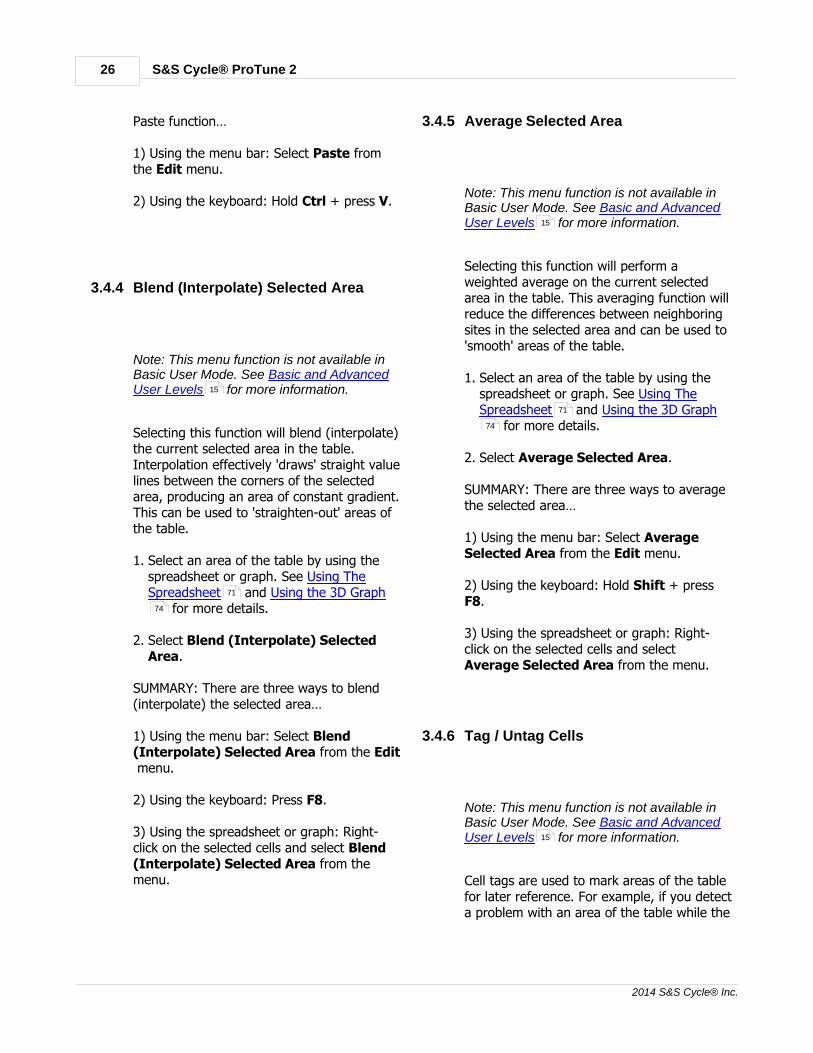
Selecting this function will blend (interpolate)the current selected area in the table.Interpolation effectively 'draws' straight valuelines between the corners of the selectedarea, producing an area of constant gradient.This can be used to 'straighten-out' areas ofthe table.
1. Select an area of the table by using thespreadsheet or graph. See Using TheSpreadsheet and Using the 3D Graph
for more details.
2. Select Blend (Interpolate) SelectedArea.
SUMMARY: There are three ways to blend(interpolate) the selected area…
1) Using the menu bar: Select Blend(Interpolate) Selected Area from the Edit menu.
2) Using the keyboard: Press F8.
3) Using the spreadsheet or graph: Right-click on the selected cells and select Blend(Interpolate) Selected Area from themenu.
3.4.5 Average Selected Area
Note: This menu function is not available inBasic User Mode. See Basic and AdvancedUser Levels for more information.
Selecting this function will perform aweighted average on the current selectedarea in the table. This averaging function willreduce the differences between neighboringsites in the selected area and can be used to'smooth' areas of the table.
1. Select an area of the table by using thespreadsheet or graph. See Using TheSpreadsheet and Using the 3D Graph
for more details.
2. Select Average Selected Area.
SUMMARY: There are three ways to averagethe selected area…
1) Using the menu bar: Select AverageSelected Area from the Edit menu.
2) Using the keyboard: Hold Shift + pressF8.
3) Using the spreadsheet or graph: Right-click on the selected cells and select Average Selected Area from the menu.
3.4.6 Tag / Untag Cells
Note: This menu function is not available inBasic User Mode. See Basic and AdvancedUser Levels for more information.
Cell tags are used to mark areas of the tablefor later reference. For example, if you detecta problem with an area of the table while the
15
71
74
15
71
74
15

Menu Functions 27
2014 S&S Cycle® Inc.
engine is running, you can mark it for laterattention by tagging the location on thetable.When a cell is tagged it appears with adownward black triangle on the graph and apurple flag on the spreadsheet:
To tag or untag a cell or group of cells:
1. Move the cursor to the cell that you wantto tag or select an area of the table byusing the spreadsheet or graph. See UsingThe Spreadsheet and Using the 3DGraph for more details.
2. Tag the cell(s) by selecting Tag / UntagCells.
3. Untag the cell(s) by selecting Tag /Untag Cells.
SUMMARY: There are three ways to tag anduntag cells…
1) Using the menu bar: Select Tag/UntagCells from the Edit menu.
2) Using the keyboard: Press F9.
3) Using the spreadsheet or graph: Right-click on a selected cell or area and select Tag/Untag Cells from the menu.
3.4.7 Clear All Markers
Note: This menu function is not available inBasic User Mode. See Basic and AdvancedUser Levels for more information.
Selecting the Clear All Markers function willclear all tags and markers currently presenton the graph and spreadsheet, including'Live-Tuned' markers and user tags. See Tag/Untag Cells for more details.
SUMMARY: There are three ways to clear allmarkers on the current table…
1) Using the menu bar: Select Clear AllMarkers from the Edit menu.
2) Using the keyboard: Press F3.
3) Using the spreadsheet or graph: Right-click on the spreadsheet or graph and select Clear All Markers from the menu.
3.4.8 Cycle Grid/Graph Position
Note: This menu function is not available inBasic User Mode. See Basic and AdvancedUser Levels for more information.
You can select the display layout of the tableusing this function. The default display layoutis with the 3D Graph at the top of the screenand the spreadsheet at the bottom of thescreen. Select Cycle Grid/Graph Positionrepeatedly to cycle through the availabledisplay layout options.
1. Select Cycle Grid/Graph Position. Thiswill place the spreadsheet at the top of thescreen and the graph at the bottom.
2. Select Cycle Grid/Graph Position again.This will remove the graph and show thetable as a spreadsheet only.
3. Select Cycle Grid/Graph Position again.This will remove the spreadsheet andshow the table as a graph only.
4. Select Cycle Grid/Graph Position again.
71
74
15
73
15

S&S Cycle® ProTune 228
2014 S&S Cycle® Inc.
This will return the display to its defaultmode with the graph at the top of thescreen and the spreadsheet at the bottom.
For more information, see Changing theSpreadsheet and Graph Layout .
SUMMARY: There are two ways to cycle theposition of the grid and graph…
1) Using the menu bar: Select Cycle Grid/Graph Position from the Edit menu.
2) Using the keyboard: Press F6.
3.4.9 Cycle Grid Size
Note: This menu function is not available inBasic User Mode. See Basic and AdvancedUser Levels for more information.
You can change the size of the cells in thespreadsheet by using this function. There arethree modes, small, normal and large. Select Cycle Grid Size repeatedly to cycle throughthe available options.
1. Select Cycle Grid Size. This will set thecell size of the spreadsheet to large.
2. Select Cycle Grid Size again. This will setthe cell size of the spreadsheet to small.
3. Select Cycle Grid Size again. This will setthe cell size of the spreadsheet back tonormal.
SUMMARY: There are two ways to cycle thegrid size of the spreadsheet…
1) Using the menu bar: Select Cycle GridSize from the Edit menu.
2) Using the keyboard: Hold Shift + pressF6.
3.4.10 Cycle Graph-Line Resolution
You can change the number of lines dividingthe 3D graph by using this function. Thereare the following three modes: highresolution (closely spaced), mediumresolution, and low resolution (widelyspaced). Select Cycle Graph-LineResolution repeatedly to cycle through theavailable options.
SUMMARY: There are two ways to cycle thegraph-line resolution of the 3D graph…
1) Using the menu bar: Select Cycle Graph-Line Resolution from the Edit menu.
2) Using the keyboard: Press F5.
3.4.11 Switch On/Off Map Cursor Pop-up
By default, a small pop-up window is shownabove the cursor in a 3D graph. It shows thetable axis values at that location.
Use the Switch On/Off Map Cursor Pop-up function to show or hide the pop-upwindow.
SUMMARY: There are two ways to switch on/off the map cursor pop-up window…
1) Using the menu bar: Select Switch On/Off Map Cursor Pop-up from the Editmenu.
2) Using the keyboard: Hold the Shift +press F7.
75
15

Menu Functions 29
2014 S&S Cycle® Inc.
3.4.12 Live-Tune Mode On/Off
Select this function to activate and deactivateLive-Tune mode. When Live-Tune mode isactivated, tuning adjustments to the currenttable have an immediate effect on the tablerunning inside the ECM.
For details on live-tuning in Basic Mode, see Live-Tune in Basic Mode .For details on live-tuning in Advanced Mode,see Live-Tune in Advanced Mode
To activate Live-Tune mode:
1. First ensure the ECM is connected. See Connecting the ECM for moreinformation.
2. Load the table that you want to Live-Tune.Select the table using the tool-bar or the View menu. Select the ECM as the currentdata source using the Current DataSource Selector at the top of the screenor from the View menu.
3. Select Live-Tune Mode On/Off .
4. ProTune 2 will automatically send newcontrol information to the ECM and Live-Tune mode will become active. Tuning thetable will now directly effect the tuning inthe ECM.
Note that during Live-Tune Mode, many ofthe program functions are disabled. Youmust deactivate Live-Tune Mode in order toreturn to normal mode.
To deactivate Live-Tune mode:
1. Select Live-Tune Mode On/Off .
2. ProTune 2 will automatically send newcontrol information to the ECM and Live-
Tune mode will deactivate.
3. The ECM is now running its original (pre-Live Tune) table. In order to utilize thechanges that you made to the table duringLive-Tune, you must send the modifiedLive-Tune table to the ECM. A messagewill appear when you deactivate Live-Tunemode asking whether you want to do this.Click Yes to send the tuned table to theECM or click No cancel any changes madein Live-Tune.
SUMMARY: There are three ways to activateor deactivate Live-Tune mode…
1) Using the tool-bar: Click the Live-Tunebutton:
2) Using the menu bar: Select Live-TuneMode On/Off from the Edit menu.
3) Using the keyboard: Hold Ctrl + press L.
3.4.13 Switch On/Off Auto-Tagging in LiveTune
Note: This menu function is not available inBasic User Mode. See Basic and AdvancedUser Levels for more information.
The Auto-Tagging feature will tag cells thatthe ECM has visited during live-tuning withblack cell markers on the graph and purplemarkers on the spreadsheet. Auto-taggingallows you to see the speeds and throttlepositions that the engine has been run atduring a Live-Tune session. Selecting SwitchOn/Off Auto-Tagging in LiveTune willtoggle this feature on or off (the default ison).
70
75
15
29
29
15

S&S Cycle® ProTune 230
2014 S&S Cycle® Inc.
If you want to manually tag cells, see Tag/Untag Cells .
SUMMARY: There are two ways to switchauto-tagging in LiveTune on/off…
1) Using the menu bar: Select Switch On/Off Auto-Tagging in LiveTune from theEdit menu.
2) Using the keyboard: Press F7.
3.4.14 Track Live-Tune Cursor
The Track Live-Tune Cursor feature enablesthe table editing cursor (blue) to follow(track) the position of the current engineposition cursor (black). This feature enablesLive-Tune value editing to take place at thecurrent engine speed and throttle position.When disabled, you can move the editingcursor freely with the cursor keys. Selecting Track Live-Tune Cursor/Don't TrackLive-Tune Cursor will toggle this feature onor off (the default is on).
SUMMARY: There are two ways to toggleLive-Tune cursor tracking.
1) Using the menu bar: Select Track Live-Tune Cursor (to enable) or Don't TrackLive-Tune Cursor (to disable) from theEdit menu.
2) Using the keyboard: Press the Space bar.
3.4.15 Snap To Live-Tune Cursor
During Live-Tune mode, you can use thisfunction to move the current editing cursorto the current position of the ECM cursor.This allows you to make adjustments at thecurrent engine speed and throttle position.This function will only function when Live-Tune cursor tracking is disabled (see TrackLive-Tune Cursor ).
SUMMARY: There are two ways to snap tothe Live-Tune cursor.
1) Using the menu bar: Select Snap ToLive-Tune Cursor from the Edit menu.
2) Using the keyboard: Hold the Ctrl key +press . (period key).
3.4.16 3D Graph Settings
You can change the axis range limits of the3D graph by selecting this function. This isuseful if you want to 'zoom-in' on a particularsection of the graph. When you choose newlimits to display a table, they are used everytime that table is loaded unless you set newlimits or restore the default limits.
1. Select 3D Graph Settings…
2. The 3D Graph Settings dialog box willappear. This box allows you to choose amaximum RPM limit for the horizontal orwidth (x) axis, a minimum and maximumlimit for the vertical or height (y) axis anda maximum Throttle % for the diagonal ordepth (z) axis.
73
30
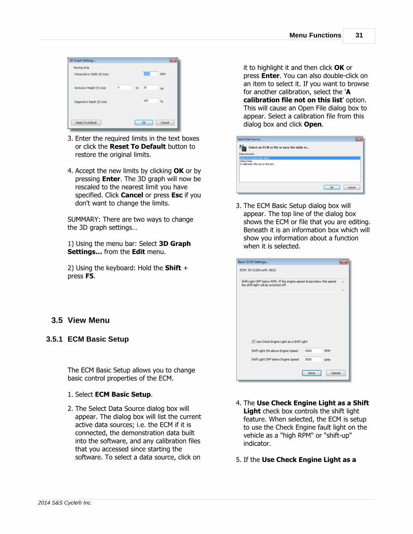
Menu Functions 31
2014 S&S Cycle® Inc.
3. Enter the required limits in the text boxesor click the Reset To Default button torestore the original limits.
4. Accept the new limits by clicking OK or bypressing Enter. The 3D graph will now berescaled to the nearest limit you havespecified. Click Cancel or press Esc if youdon't want to change the limits.
SUMMARY: There are two ways to changethe 3D graph settings…
1) Using the menu bar: Select 3D GraphSettings… from the Edit menu.
2) Using the keyboard: Hold the Shift +press F5.
3.5 View Menu
3.5.1 ECM Basic Setup
The ECM Basic Setup allows you to changebasic control properties of the ECM.
1. Select ECM Basic Setup.
2. The Select Data Source dialog box willappear. The dialog box will list the currentactive data sources; i.e. the ECM if it isconnected, the demonstration data builtinto the software, and any calibration filesthat you accessed since starting thesoftware. To select a data source, click on
it to highlight it and then click OK orpress Enter. You can also double-click onan item to select it. If you want to browsefor another calibration, select the 'Acalibration file not on this list' option.This will cause an Open File dialog box toappear. Select a calibration file from thisdialog box and click Open.
3. The ECM Basic Setup dialog box willappear. The top line of the dialog boxshows the ECM or file that you are editing.Beneath it is an information box which willshow you information about a functionwhen it is selected.
4. The Use Check Engine Light as a ShiftLight check box controls the shift lightfeature. When selected, the ECM is setupto use the Check Engine fault light on thevehicle as a "high RPM" or "shift-up"indicator.
5. If the Use Check Engine Light as a

S&S Cycle® ProTune 232
2014 S&S Cycle® Inc.
Shift Light property is selected, you mayspecify the engine speed at which the shiftlight illuminates, Shift Light ON aboveEngine Speed. You may also specify theengine speed at which the shift light willcancel, Shift Light OFF below EngineSpeed.
6. The Break-In Limiter System Enabled(for 55-5069 USB modules only) checkbox controls the Break-In limiter function. Note: The Break-In Rev Limit Statuscan only be viewed from an ECM. Thebreak-in limiter automatically sets the rev-limit for an initial period of running a newengine, allowing the new engine to beproperly broken-in. Once the Break-Inlimiter function is enabled, it cannot bedisabled until the break-in limiter time haselapsed. The length of this period,together with the current rev-limit, can befound in the ECM Information dialogpage Rev Limiting tab. If the Break-InLimiter System Enabled checkbox ischecked, this means the break-in limiter iscurrently active and will be deactivatedonce the break-in period is complete. Ifthe box is unchecked, you can enable thebreak-in limiting period by checking thebox and clicking Save.
7. The Wheel Speed Gear Factor (for 55-
5069 USB modules only) is a valueused by the ECM to scale the input fromthe wheel speed sensor to drive thespeedometer and mileage counter. Youcan adjust this value by entering apercentage. 100% represents 50000counts per kilometer (50000 pulses fromthe wheel speed sensor equals 1000meters traveled). The calculated numberof counts per kilometer is also shown. Thevalid range for the percentage value is 5%(2500 counts per kilometer) to 165%(82500 counts per kilometer).
When you have finished viewing or editingthe properties, click OK or press Enter tosave the changes to the current data source. Click Cancel or press Esc if you do not wish
to save the changes.
If this software is in Advanced Mode, theECM Basic Setup dialog box will allow you toset the Rev Limiter SOFT Cut. When theengine is above the SOFT Cut threshold, theECM will only fire every other spark to reducepower. When you set the soft-cut limit, the Rev Limiter HARD Cut is automatically set250 RPM above the soft-cut threshold. Whenthe engine is above the hard-cut limit, theECM will not fire any sparks.
SUMMARY: There are three ways to accessthe ECM Basic Setup…
1) Using the tool bar: Click the Setup button
2) Using the menu bar: Select ECM BasicSetup from the View menu.
3) Using the keyboard: Hold Ctrl + press 1.
48
53

Menu Functions 33
2014 S&S Cycle® Inc.
3.5.2 Diagnostic Trouble Codes
The Diagnostic Trouble Codes feature showsyou the current trouble code status andhistoric trouble code status of the connectedS&S® ECM.
1. To view current diagnostic info, ensure theECM is connected. See Connecting theECM for more information. 55-5069ECMs with the appropriate calibration filecan also retrieve freeze-frame diagnosticinformation.
2. Select Diagnostic Trouble Codes.
3. The Select Data Source dialog box willappear. The dialog box will list the currentactive data sources; i.e. the ECM if it isconnected, the demonstration data builtinto the software, and any calibration filesthat you accessed since starting thesoftware. To view live and currentdiagnostic data, you must select the ECMas the data source. To select a datasource, click on it to highlight it and thenclick OK or press Enter. You can alsodouble-click on an item to select it. If youwant to browse for another calibration,select the 'A calibration file not on thislist' option. This will cause an Open Filedialog box to appear. Select a calibrationfile from this dialog box and click Open.
4. The Diagnostic Trouble Codes dialog box
will appear. When viewing diagnosticinformation from calibration files, theCurrent DTC Error message field and listare not applicable and will not be shown.
5. The top section is the Current DTCError box. This displays a scrolling list ofthe current faults detected by the system.If there are no current faults the message'No Current Trouble Codes' will bedisplayed on a green background. If thereare current faults detected, the number ofcurrent faults will be displayed, followedby each fault displayed in turn on a redbackground.
6. The Current Diagnostic Trouble CodeList displays the current faults as a list,together with their P-Codes (standardautomotive codes for vehicle faults).
7. The Historic Diagnostic Trouble CodeList displays all faults logged since thecodes were last reset. For certain ECMswith the appropriate calibration file,freeze-frame data may be available forsome of the items logged in the list.Freeze-frame data logs key engineparameters when the fault occurred. If ahistoric trouble-code has freeze-framedata, 'Yes' will be shown in the 'Freeze-Frame?' column. You can view the databy selecting the fault in the list andclicking Historic Freeze-Frame Data...The parameters logged are EngineMileage, Trip Count, Engine Speed,Throttle Voltage and the Time spent With
15

S&S Cycle® ProTune 234
2014 S&S Cycle® Inc.
Fault active. Click OK or press Enter todismiss this box.
8. Close the Diagnostic Trouble Codes dialogbox by clicking Exit or pressing Enter. Ifyou want to clear the list of historictrouble-codes in the ECM, click ClearHistoric DTCs. The message 'HistoricTrouble-Codes Reset' will appear. Click OK. You will then be returned to the Diagnostic Trouble Codes dialog box. Notethat if there are current faults, historicfaults will always reappear.
SUMMARY: There are three ways to accessthe DTCs dialog box…
1) Using the tool bar: Click the DTCs button:
2) Using the menu bar: Select DiagnosticTrouble Codes from the View menu.
3) Using the keyboard: Hold Ctrl + press 2
3.5.3 ECM Gauges
Selecting the ECM Gauges function will openthe Gauges display, a configurable displaythat allows you to view various ECMparameters in real-time.
1. Ensure the ECM is connected if you wantto view live data. Without the ECMconnected you can only change the layout
of the gauges window. See Connecting theECM for more information.
2. Select ECM Gauges.
3. The ECM Gauges window will appear. Thiscan be moved and resized independentlyof the main window. To close the window,click the close button (X) in the top-rightcorner. For more information on thisinterface, see Using the Gauges Window
.
SUMMARY: There are three ways to view theGauges display …
1) Using the tool bar: Click the Gaugesbutton:
2) Using the menu bar: Select ECM Gaugesfrom the View menu.
3) Using the keyboard: Hold Ctrl + press 3
15
78

Menu Functions 35
2014 S&S Cycle® Inc.
3.5.4 Fuel Injection Base Table
Selecting this option will load the FuelInjection Base Table from the current datasource. This table is used as the base tablefor calculating the current fuel injector pulsewidth. See The Fuel Injection System formore information on this table.
You can change the current data source byeither selecting an option from the CurrentData Source drop-down list at the top of thescreen, or from the Current Data Sourcemenu in the View menu. Alternatively,you can select Open Table from… fromthe Options menu.
SUMMARY: There are three ways to accessthe Fuel Injection Base Table…
1) Using the tool bar: Click the Fuel button:
2) Using the menu bar: Select FuelInjection Base Table from the Viewmenu.
3) Using the keyboard: Hold Ctrl + press 4.
3.5.5 Ignition Timing Base Table
Selecting this option will load the IgnitionTiming Base Table from the current datasource. This table is used as the base tablefor calculating the current ignition advance indegrees before Top Dead Center. See TheIgnition Timing System for moreinformation on this table.
You can change the current data source byeither selecting an option from the CurrentData Source drop-down list at the top of thescreen, or from the Current Data Source
menu in the View menu.Alternatively,you can select Open Table from… fromthe Options menu.
SUMMARY: There are three ways to accessthe Ignition Timing Base Table…
1) Using the tool bar: Click the Ignitionbutton:
2) Using the menu bar: Select IgnitionTiming Base Table from the View menu.
3) Using the keyboard: Hold Ctrl + press 5.
3.5.6 Front Cylinder Adjustment Table
Selecting this option will load the FrontCylinder Adjustment Table from the currentdata source. This table is used to adjust thefuel delivery for each cylinder. See The FuelInjection System for more information onthis table.
You can change the current data source byeither selecting an option from the CurrentData Source drop-down list at the top of thescreen, or from the Current Data Sourcemenu in the View menu. Alternatively,you can select Open Table from… fromthe Options menu.
SUMMARY: There are three ways to accessthe Front Cylinder Adjustment Table…
1) Using the tool bar: Click the Front button:
2) Using the menu bar: Select FrontCylinder Fuel Adjustment Table from theView menu.
3) Using the keyboard: Hold Ctrl + press 6.
65
47
59
66
47
59
65
47
59

S&S Cycle® ProTune 236
2014 S&S Cycle® Inc.
3.5.7 Rear Cylinder Adjustment Table
Selecting this option will load the RearCylinder Adjustment Table from the currentdata source. This table is used to adjust thefuel delivery for each cylinder. See The FuelInjection System for more information onthis table.
You can change the current data source byeither selecting an option from the CurrentData Source drop-down list at the top of thescreen, or from the Current Data Sourcemenu in the View menu. Alternatively,you can select Open Table from… fromthe Options menu.
SUMMARY: There are three ways to accessthe Rear Cylinder Adjustment Table…
1) Using the tool bar: Click the Rear button:
2) Using the menu bar: Select RearCylinder Fuel Adjustment Table from theView menu.
3) Using the keyboard: Hold Ctrl + press 7.
3.5.8 Acceleration Fuel Settings
The Acceleration Fuel Settings function in theECM improves acceleration by adjusting fueldelivery according to throttle movement.When the throttle is opened, additional fuelallows the engine to accelerate quickly.
1. Select Acceleration Fuel Settings.
2. The Select Data Source dialog box willappear. The dialog box will list the currentactive data sources; i.e. the ECM if it isconnected, the demonstration data built
into the software, and any calibration filesthat you accessed since starting thesoftware. To select a data source, click onit to highlight it and then click OK orpress Enter. You can also double-click onan item to select it. If you want to browsefor another calibration, select the 'Acalibration file not on this list' option.This will cause an Open File dialog box toappear. Select a calibration file from thisdialog box and click Open.
3. The Acceleration Fuel Settings dialog boxwill appear. You can select from three Sensitivity settings (Low, Medium andHigh) and three Volume settings(Minimum, Medium and Maximum).
4. The Sensitivity setting sets how responsivethe accel fuel system is to throttlemovement. A low sensitivity means thatlarge throttle movements will be requiredto trigger changes in the fuel delivery. Ahigh sensitivity means that small throttlemovements will trigger changes in the fueldelivery. Select an option by clicking onthe list's down arrow. If the option is setto Default (Retain factory settings) the
65
47
59

Menu Functions 37
2014 S&S Cycle® Inc.
data in the data source that you areediting won't be altered from its currentsetting.
5. The Volume setting sets how large theboost in fuel delivery is when the accel istriggered. A minimum volume means thechange in fuel delivery will be relativelysmall. A maximum volume means thechange in fuel delivery will be relativelylarge. Select an option by clicking on thelist's down arrow. If the option is set to Default (Retain factory settings) the datain the data source that you are editingwon't be altered from its current setting.
6. Click Cancel or press Esc if you do notwant to save the changes to the settings.Click Save or press Enter to store yournew accel setup. The Select Data Sourcedialog box will appear. Select where youwant to save the Accel Fuel settings fromthe dialog box and click OK or press Enterto save to the selected data source. Youcan also click Cancel or press Esc tocancel the change.
SUMMARY: There are three ways to accessthe Acceleration Fuel Settings…
1) Using the tool bar: Click the Accel button:
2) Using the menu bar: Select AccelerationFuel Settings from the View menu.
3) Using the keyboard: Hold Ctrl + press 8.
3.5.9 Closed-Loop Control Settings
This dialog box allows you to set the Closed-Loop fuel control mode in the S&S® ECM orcalibration file. The Closed-Loop system is afeature that allows the ECM to learn fueldelivery based upon comparing thecalibration fuel mixture against the actualfuel mixture measured by the oxygen sensorsin the exhaust system. See the section on The Closed-Loop Fuel Control System formore details.
1. Select Closed-Loop Control Settings.
2. The Select Data Source dialog box willappear. The dialog box will list the currentactive data sources; i.e. the ECM if it isconnected, the demonstration data builtinto the software, and any calibration filesthat you accessed since starting thesoftware. To select a data source, click onit to highlight it and then click OK orpress Enter. You can also double-click onan item to select it. If you want to browsefor another calibration, select the 'Acalibration file not on this list' option.This will cause an Open File dialog box toappear. Select a calibration file from thisdialog box and click Open.
3. The Closed-Loop Control Settings dialogbox will now appear. For details on how touse this dialog box in Basic Mode, see Closed-Loop Setup in Basic Mode . Fordetails on how to use this dialog box inAdvanced Mode, see Closed-Loop Setup inAdvanced Mode .
4. Click Cancel or press Esc if you do not
83
84
85

S&S Cycle® ProTune 238
2014 S&S Cycle® Inc.
want to save the changes that you havemade to the settings. Click Save or pressEnter to store your new Closed-Loopsetup in the data source that you areediting (shown at the top of the dialogbox).
SUMMARY: There are two ways to access theClosed-Loop Control Settings…
1) Using the menu bar: Select Closed-LoopControl Settings from the View menu.
2) Using the keyboard: Hold Ctrl + press 9.
3.5.10 Knock Control Settings
For 55-5069 USB modules only. Thisdialog box allows you to set the KnockControl mode in the S&S® ECM or calibrationfile. The Knock Control system adjustsignition timing to avoid engine knocking. SeeThe Knock (Adaptive Ignition) ControlSystem for more details.
1. Select Knock Control Settings.
2. The Select Data Source dialog box willappear. The dialog box will list the currentactive data sources; i.e. the ECM if it isconnected, the demonstration data builtinto the software, and any calibration filesthat you accessed since starting thesoftware. To select a data source, click onit to highlight it and then click OK orpress Enter. You can also double-click onan item to select it. If you want to browsefor another calibration, select the 'Acalibration file not on this list' option.This will cause an Open File dialog box toappear. Select a calibration file from thisdialog box and click Open.
3. The Knock Control Settings dialog box willnow appear.
4. Select a control mode from the drop-downlist. Please see The Knock (AdaptiveIgnition) Control System for moredetails.
5. To save the new setting, click Save orpress Enter. To exit without saving anychanges, click Cancel or press Esc.
SUMMARY: There are two ways to access theKnock Control Settings…
1) Using the menu bar: Select KnockControl Settings from the View menu.
2) Using the keyboard: Hold Ctrl + press 0.
3.5.11 Engine Temperature Ignition Compensation
Note: This menu function is not available inBasic User Mode. See Basic and AdvancedUser Levels for more information.
88
88
15

Menu Functions 39
2014 S&S Cycle® Inc.
Selecting this option will allow you to viewand edit the Engine Temperature IgnitionCompensation table. This table specifies theadjustments made by the ECM to the ignitiontiming as a function of the temperature ofthe engine. See Temperature CompensationTables for more details on this table.
1. Select Engine Temperature IgnitionCompensation.
2. The Select Data Source dialog box willappear. The dialog box will list the currentactive data sources; i.e. the ECM if it isconnected, the demonstration data builtinto the software, and any calibration filesthat you accessed since starting thesoftware. To select a data source, click onit to highlight it and then click OK orpress Enter. You can also double-click onan item to select it. If you want to browsefor another calibration, select the 'Acalibration file not on this list' option.This will cause an Open File dialog box toappear. Select a calibration file from thisdialog box and click Open.
3. The table will now load. See Viewing andEditing Advanced Tables for moredetails.
SUMMARY: There are two ways to access theEngine Temperature Ignition Compensationtable…
1) Using the menu bar: Select EngineTemperature Ignition Compensationfrom the View menu.
2) Using the keyboard: Hold Ctrl + Shift +
press 1.
3.5.12 Air Temperature Ignition Compensation
Note: This menu function is not available inBasic User Mode. See Basic and AdvancedUser Levels for more information.
Selecting this option will allow you to viewand edit the Air Temperature IgnitionCompensation table. This table specifies theadjustments made by the ECM to the ignitiontiming as a function of the ambient airtemperature. See TemperatureCompensation Tables for more details onthis table.
1. Select Air Temperature IgnitionCompensation.
2. The Select Data Source dialog box willappear. The dialog box will list the currentactive data sources; i.e. the ECM if it isconnected, the demonstration data builtinto the software, and any calibration filesthat you accessed since starting thesoftware. To select a data source, click onit to highlight it and then click OK orpress Enter. You can also double-click onan item to select it. If you want to browsefor another calibration, select the 'Acalibration file not on this list' option.This will cause an Open File dialog box toappear. Select a calibration file from thisdialog box and click Open.
82
81
15
82

S&S Cycle® ProTune 240
2014 S&S Cycle® Inc.
3. The table will now load. See Viewing andEditing Advanced Tables for moredetails.
SUMMARY: There are two ways to access theAir Temperature Ignition Compensationtable…
1) Using the menu bar: Select AirTemperature Ignition Compensationfrom the View menu.
2) Using the keyboard: Hold Ctrl + Shift +press 2.
3.5.13 Engine Temperature Fuel Compensation
Note: This menu function is not available inBasic User Mode. See Basic and AdvancedUser Levels for more information.
Selecting this option will allow you to viewand edit the Engine Temperature FuelCompensation table. This table specifies theadjustments made by the ECM to the fueldelivery as a function of the temperature ofthe engine. See Temperature CompensationTables for more details on this table.
1. Select Engine Temperature FuelCompensation.
2. The Select Data Source dialog box willappear. The dialog box will list the currentactive data sources; i.e. the ECM if it isconnected, the demonstration data builtinto the software, and any calibration filesthat you accessed since starting thesoftware. To select a data source, click onit to highlight it and then click OK orpress Enter. You can also double-click onan item to select it. If you want to browsefor another calibration, select the 'Acalibration file not on this list' option.This will cause an Open File dialog box to
appear. Select a calibration file from thisdialog box and click Open.
3. The table will now load. See Viewing andEditing Advanced Tables for moredetails.
SUMMARY: There are two ways to access theEngine Temperature Fuel Compensationtable…
1) Using the menu bar: Select EngineTemperature Fuel Compensation fromthe View menu.
2) Using the keyboard: Hold Ctrl + Shift +press 3.
3.5.14 Air Temperature Fuel Compensation
Note: This menu function is not available inBasic User Mode. See Basic and AdvancedUser Levels for more information.
Selecting this option will allow you to viewand edit the Air Temperature FuelCompensation table. This table specifies theadjustments made by the ECM to the fueldelivery as a function of the ambient airtemperature. See TemperatureCompensation Tables for more details onthis table.
1. Select Air Temperature FuelCompensation.
81
15
82
81
15
82

Menu Functions 41
2014 S&S Cycle® Inc.
2. The Select Data Source dialog box willappear. The dialog box will list the currentactive data sources; i.e. the ECM if it isconnected, the demonstration data builtinto the software, and any calibration filesthat you accessed since starting thesoftware. To select a data source, click onit to highlight it and then click OK orpress Enter. You can also double-click onan item to select it. If you want to browsefor another calibration, select the 'Acalibration file not on this list' option.This will cause an Open File dialog box toappear. Select a calibration file from thisdialog box and click Open.
3. The table will now load. See Viewing andEditing Advanced Tables for moredetails.
SUMMARY: There are two ways to access theAir Temperature Fuel Compensation table…
1) Using the menu bar: Select AirTemperature Fuel Compensation fromthe View menu.
2) Using the keyboard: Hold Ctrl + Shift +press 4.
3.5.15 Engine Temperature Start Map
Note: This menu function is not available inBasic User Mode. See Basic and AdvancedUser Levels for more information.
Selecting this option will allow you to viewand edit the Engine Temperature Start Maptable. This table specifies the adjustmentsmade by the ECM to the fuel delivery duringengine cranking as a function of thetemperature of the engine. See EngineTemperature Start Map for more detailson this table.
1. Select Engine Temperature Start Map.
2. The Select Data Source dialog box willappear. The dialog box will list the currentactive data sources; i.e. the ECM if it isconnected, the demonstration data builtinto the software, and any calibration filesthat you accessed since starting thesoftware. To select a data source, click onit to highlight it and then click OK orpress Enter. You can also double-click onan item to select it. If you want to browsefor another calibration, select the 'Acalibration file not on this list' option.This will cause an Open File dialog box toappear. Select a calibration file from thisdialog box and click Open.
3. The table will now load. Viewing andEditing Advanced Tables for moredetails.
SUMMARY: There are two ways to access theEngine Temperature Start Map…
1) Using the menu bar: Select EngineTemperature Start Map from the Viewmenu.
2) Using the keyboard: Hold Ctrl + Shift +press 5.
81
15
82
81

S&S Cycle® ProTune 242
2014 S&S Cycle® Inc.
3.5.16 Stepper Motor Orientation Setting
Note: This menu function is not available inBasic User Mode. See Basic and AdvancedUser Levels for more information.
The stepper-motor on your vehicle is used tocontrol the idle speed of the engine byautomatically making small adjustments tothe throttle position.
The Stepper Motor Orientation Setting allowsfor different orientation of stepper motorwiring. The orientation should be left asdefault unless you have reason to alter it.The correct orientation is such that thestepper position increases as engine speedincreases.
1. Select Stepper Motor OrientationSetting.
2. The Select Data Source dialog box willappear. The dialog box will list the currentactive data sources; i.e. the ECM if it isconnected, the demonstration data builtinto the software, and any calibration filesthat you accessed since starting thesoftware. To select a data source, click onit to highlight it and then click OK orpress Enter. You can also double-click onan item to select it. If you want to browsefor another calibration, select the 'Acalibration file not on this list' option.This will cause an Open File dialog box toappear. Select a calibration file from thisdialog box and click Open.
3. The Stepper Motor Orientation Setting
dialog box will appear. Select Normal orReversed from the drop-down list byclicking on the down arrow.
4. Click Save or press Enter to set the newmode, click Cancel or press Esc to cancelany changes.
5. When you have altered the Stepper MotorOrientation Setting in an ECM, a messagebox will appear advising you to cyclepower to the ECM (turn key off for at least15 seconds) before continuing. This willallow the ECM to power-up using the newstepper motor orientation.
SUMMARY: There are two ways to access theStepper Motor Orientation Setting…
1) Using the menu bar: Select StepperMotor Orientation Setting from the Viewmenu.
2) Using the keyboard: Hold Ctrl + Shift +press 6.
3.5.17 Stepper Pre-Start Position Map
Note: This menu function is not available inBasic User Mode. See Basic and AdvancedUser Levels for more information.
The stepper-motor on your vehicle is used tocontrol the idle speed of the engine byautomatically making small adjustments to
15
15

Menu Functions 43
2014 S&S Cycle® Inc.
the throttle position.
The Stepper Pre-Start Position Map allowsyou to set the initial position of the steppermotor during cranking as a function ofengine temperature. See Stepper MotorTables (Idle Speed Control) for moredetails on this map.
1. Select Stepper Pre-Start Position Map.
2. The Select Data Source dialog box willappear. The dialog box will list the currentactive data sources; i.e. the ECM if it isconnected, the demonstration data builtinto the software, and any calibration filesthat you accessed since starting thesoftware. To select a data source, click onit to highlight it and then click OK orpress Enter. You can also double-click onan item to select it. If you want to browsefor another calibration, select the 'Acalibration file not on this list' option.This will cause an Open File dialog box toappear. Select a calibration file from thisdialog box and click Open.
3. The table will now load. See Viewing andEditing Advanced Tables for moredetails.
SUMMARY: There are two ways to access theStepper Pre-Start Position Map…
1) Using the menu bar: Select Stepper Pre-Start Position Map from the View menu.
2) Using the keyboard: Hold Ctrl + Shift +press 7.
3.5.18 Stepper Position with Temperature Map
Note: This menu function is not available inBasic User Mode. See Basic and AdvancedUser Levels for more information.
The stepper-motor on your vehicle is used tocontrol the idle speed of the engine byautomatically making small adjustments tothe throttle position.
The Stepper Position with Temperature Mapallows you to set the initial position of thestepper motor during engine running as afunction of engine temperature. See StepperMotor Tables (Idle Speed Control) formore details on this map.
1. Select Stepper Position withTemperature Map.
2. The Select Data Source dialog box willappear. The dialog box will list the currentactive data sources; i.e. the ECM if it isconnected, the demonstration data builtinto the software, and any calibration filesthat you accessed since starting thesoftware. To select a data source, click onit to highlight it and then click OK orpress Enter. You can also double-click onan item to select it. If you want to browsefor another calibration, select the 'Acalibration file not on this list' option.This will cause an Open File dialog box toappear. Select a calibration file from thisdialog box and click Open.
3. The table will now load. See Viewing and
82
81
15
82

S&S Cycle® ProTune 244
2014 S&S Cycle® Inc.
Editing Advanced Tables for moredetails.
SUMMARY: There are two ways to access theStepper Position with Temperature table…
1) Using the menu bar: Select StepperPosition with Temperature from theView menu.
2) Using the keyboard: Hold Ctrl + Shift +press 8.
3.5.19 Target Idle Speed Setting
Note: This menu function is not available inBasic User Mode. See Basic and AdvancedUser Levels for more information.
This function allows you to set the target idlespeed setting of the ECM. This is the RPMvalue that the ECM will try to attain whenidling.
After the engine is started, the target idlespeed is set to the optimum value for theengine temperature and conditions. As thevehicle engine warms-up the ECM will movethe idle speed towards the value that youspecify. See Stepper Motor Tables (IdleSpeed Control) for more details.
1. Select Target Idle Speed Setting.
2. The Select Data Source dialog box willappear. The dialog box will list the currentactive data sources; i.e. the ECM if it isconnected, the demonstration data builtinto the software, and any calibration filesthat you accessed since starting thesoftware. To select a data source, click onit to highlight it and then click OK orpress Enter. You can also double-click onan item to select it. If you want to browsefor another calibration, select the 'A
calibration file not on this list' option.This will cause an Open File dialog box toappear. Select a calibration file from thisdialog box and click Open.
3. The target idle speed data will now beloaded from the ECM/Tune-File and the Target Idle Speed Setting dialog box willappear.
4. Enter a new target idle speed between900 and 1100 RPM in the edit box.
5. Click Save or press Enter to set the newvalue. Click Cancel or press Esc todiscard any changes.
SUMMARY: There are two ways to access theTarget Idle Speed Setting…
1) Using the menu bar: Select Target IdleSpeed Setting from the View menu.
2) Using the keyboard: Hold Ctrl + Shift +press 9.
81
15
82

Menu Functions 45
2014 S&S Cycle® Inc.
3.5.20 Stepper Position Fuel Compensation
Note: This menu function is not available inBasic User Mode. See Basic and AdvancedUser Levels for more information.
The stepper position fuel compensationfeature adjusts fuel delivery as a function ofthe stepper motor position. The steppermotor controls the throttle valve used for idlespeed control. See Stepper Motor Tables(Idle Speed Control) for more details.When this table is saved to an ECM, it willhave no effect unless the checkbox locatedbelow the spreadsheet is checked.
1. Select Stepper Position FuelCompensation.
2. The Select Data Source dialog box willappear. The dialog box will list the currentactive data sources; i.e. the ECM if it isconnected, the demonstration data builtinto the software, and any calibration filesthat you accessed since starting thesoftware. To select a data source, click onit to highlight it and then click OK orpress Enter. You can also double-click onan item to select it. If you want to browsefor another calibration, select the 'Acalibration file not on this list' option.This will cause an Open File dialog box toappear. Select a calibration file from thisdialog box and click Open.
3. The table will now load. See Viewing andEditing Advanced Tables for moredetails.
SUMMARY: There are two ways to access theStepper Position Fuel Compensation table…
1) Using the menu bar: Select StepperPosition Fuel Compensation from theView menu.
2) Using the keyboard: Hold Ctrl + Shift +press B.
3.5.21 Front Cylinder Adaptive Map
Note: This menu function is not available inBasic User Mode. See Basic and AdvancedUser Levels for more information.
Selecting this function allows you to view theFront cylinder adaptive fuel table from theECM. This table is only accessible if an ECMsupporting Closed-Loop Fuel Control isconnected. The table can only be viewed, itcannot be modified as its values aregenerated internally by the ECM.
The adaptive maps are fuel trim maps thatthe ECM learns based upon the results ofClosed-Loop Fuel Control. For more detailson this subject see The Closed-Loop FuelControl System .
1. Ensure the ECM is connected. See Connecting the ECM for moreinformation.
2. Select Front Cylinder Adaptive Map.The map will now be loaded anddisplayed.
SUMMARY: There are two ways to access theFront Cylinder Adaptive Map…
15
82
81
15
83
15

S&S Cycle® ProTune 246
2014 S&S Cycle® Inc.
1) Using the menu bar: Select FrontCylinder Adaptive Map from the Viewmenu. Note this menu item will only beshown when an ECM supporting Closed-LoopFuel Control is connected.
2) Using the keyboard: Hold Ctrl + Shift +press C.
3.5.22 Rear Cylinder Adaptive Map
Note: This menu function is not available inBasic User Mode. See Basic and AdvancedUser Levels for more information.
Selecting this function allows you to view theRear cylinder adaptive fuel table from theECM. This table is only accessible if an ECMsupporting Closed-Loop Fuel Control isconnected. The table can only be viewed, itcannot be modified as its values aregenerated internally by the ECM.
The adaptive maps are fuel trim maps thatthe ECM learns based upon the results ofClosed-Loop Fuel Control. For more detailson this subject see The Closed-Loop FuelControl System .
1. Ensure the ECM is connected. See Connecting the ECM for moreinformation.
2. Select Rear Cylinder Adaptive Map.The map will now be loaded anddisplayed.
SUMMARY: There are two ways to access theRear Cylinder Adaptive Map…
1) Using the menu bar: Select RearCylinder Adaptive Map from the Viewmenu. Note this menu item will only beshown when an ECM supporting Closed-LoopFuel Control is connected.
2) Using the keyboard: Hold Ctrl + Shift +press D.
3.5.23 Target Closed-Loop Fuel Map
Note: This menu function is not available inBasic User Mode. See Basic and AdvancedUser Levels for more information.
This item allows you to view the TargetClosed-Loop Fuel Map in an S&S® ECM orCalibration File. The Closed-Loop system is afeature that allows the ECM to learn fueldelivery based upon comparing thecalibration fuel mixture against the actualfuel mixture measured by the oxygen sensorsin the exhaust system. See the section on The Closed-Loop Fuel Control System formore details.
1. Select Target Closed-Loop Fuel Map.
2. The Select Data Source dialog box willappear. The dialog box will list the currentactive data sources; i.e. the ECM if it isconnected, the demonstration data builtinto the software, and any calibration filesthat you accessed since starting thesoftware. To select a data source, click onit to highlight it and then click OK orpress Enter. You can also double-click onan item to select it. If you want to browsefor another calibration, select the 'Acalibration file not on this list' option.This will cause an Open File dialog box toappear. Select a calibration file from thisdialog box and click Open.
15
83
15
15
83

Menu Functions 47
2014 S&S Cycle® Inc.
3. The Target Closed-Loop Fuel Map will nowbe loaded and displayed. Please see Setting the Target Air-Fuel Mixture formore details on editing this table.
SUMMARY: There are two ways to access theTarget Closed-Loop Fuel Map…
1) Using the menu bar: Select TargetClosed-Loop Fuel Map from the Viewmenu.
2) Using the keyboard: Hold Ctrl + Shift +press E.
3.5.24 Adaptive Ignition Map
Note: This menu function is not available inBasic User Mode. See Basic and AdvancedUser Levels for more information.
For 55-5069 USB modules only. Selecting this function allows you to view theAdaptive Ignition Map. This map stores thecurrent long-term ignition adjustments theECM learns based upon the feedback of theknock sensor. The table can only be viewed,it cannot be modified as its values aregenerated internally by the ECM. See TheKnock (Adaptive Ignition) Control Systemfor more details.
1. Ensure the ECM is connected. See Connecting the ECM for moreinformation.
2. Select Adaptive Ignition Map. The mapwill now be loaded and displayed.
SUMMARY: There are two ways to access theAdaptive Ignition Map…
1) Using the menu bar: Select AdaptiveIgnition Map from the View menu. Notethis menu item will only be shown when anECM supporting Knock Control is connected.
2) Using the keyboard: Hold Ctrl + Shift +press F.
3.5.25 Current Data Source menu
The Current Data Source menu allowsyou to load the current table from anotherdata source. From the menu you can choosebetween the ECM (if connected), the DemoData, any calibrations that you haveaccessed since the software started, or selectthe 'Calibration not in this list' option tobrowse for another calibrations. Selecting the'Calibration not in this list' option will causethe Open File dialog box to appear. Select afile by clicking on its file name and click Open.
SUMMARY: There are two ways to changethe current data source…
1) Using the tool bar: Select an item fromthe Current Data Source drop down listbox on the tool-bar.
2) Using the menu bar: Access the CurrentData Source menu in the View menu.Select one of the items in the menu.
86
15
88
15

S&S Cycle® ProTune 248
2014 S&S Cycle® Inc.
3.5.26 Comment Field
Every ECM and calibration file has a smallarea of memory reserved for a comment-field. The comment-field allows a tuner todescribe the configuration and contents ofthe ECM/File. Each calibration file supplied byS&S Cycle® contains a comment fielddescribing the particular configuration of thatfile. The comment-field is shown when youselect a calibration file in the Open File orSave File dialog boxes. For some ECMs/filesthe comment field is read-only and cannot bechanged.
To view or edit the comment-field in yourECM or a calibration file, follow these steps:
1. Select Comment Field…
2. The Select Data Source dialog box willappear. The dialog box will list the currentactive data sources; i.e. the ECM if it isconnected, the demonstration data builtinto the software, and any calibration filesthat you accessed since starting thesoftware. To select a data source, click onit to highlight it and then click OK orpress Enter. You can also double-click onan item to select it. If you want to browsefor another calibration, select the 'Acalibration file not on this list' option.This will cause an Open File dialog box toappear. Select a calibration file from thisdialog box and click Open.
3. The View Comment Field dialog box willappear. The data source that you areviewing is displayed at the top of the
dialog box. In the white text box you canview the comment text. The comment fieldtext is limited to a maximum of 512characters.
4. Click Cancel or press Esc if you do notwish to change the comment-field. Click OK or press Enter to store the newcomment in the data source that you areediting (shown at the top of the dialogbox). If the comment-field is read-only,you will not be able to change the text.
SUMMARY: There are two ways to view thecomment field in the ECM or a calibrationfile…
1) Using the menu bar: Select CommentField from the View menu.
2) Using the keyboard: Hold Ctrl + press F.
3.5.27 ECM Information
The ECM Information function allows you toview engine operation statistics in your ECMand calibration files. This includes historicdata on ECM use and engine performance.
To access the ECM Information dialog box:
1. Select ECM Information.
2. The Select Data Source dialog box willappear. The dialog box will list the currentactive data sources; i.e. the ECM if it is

Menu Functions 49
2014 S&S Cycle® Inc.
connected, the demonstration data builtinto the software, and any calibration filesthat you accessed since starting thesoftware. To select a data source, click onit to highlight it and then click OK orpress Enter. You can also double-click onan item to select it. If you want to browsefor another calibration, select the 'Acalibration file not on this list' option.This will cause an Open File dialog box toappear. Select a calibration file from thisdialog box and click Open.
3. The ECM Information dialog box willappear. The dialog box is arranged inpages. Select the tabs at the top of thedialog box to switch between the pages.The ECM page describes generalproperties and identifiers of the ECM andcalibration files that support thisinformation. The Stats Overview pagedetails the overall statistics of the ECM andengine. The Engine Use page displaysa chart of time the engine has spent inranges of engine speed, throttle positionand engine temperature. The Peaks page
shows the highest values of keyparameters and are logged over the life ofthe ECM. The Last Trip Peaks pageshows the highest values of keyparameters logged over the last four trips(a trip is running the vehicle for fiveminutes or more). The Rev Limiting page
shows how often the engine revlimiter has been hit and also describes thecurrent break-in limiter status andschedule (see ECM Basic Setup for moredetails).
4. The ECM Information dialog shows asnapshot of the ECM state. To refresh thisinformation at any time, click Refresh.
5. The contents of all pages of the ECMInformation dialog may be saved to a textfile and viewed in a text editor such asNotepad, Wordpad or Excel®. To do this,click Save. A Save As dialog box willappear. The default folder for ECMInformation is My Documents\ProTune 2\ECM Information Data. Enter a filenameand click Save. The file produced is a .tsv(tab separated value file) which can beviewed in any text editor but is bestviewed in a spreadsheet application likeExcel®.
6. To close the ECM Information dialog box,click Exit or press Esc.
The ECM Information dialog box allows useof the Engine Rebuild function. The EngineRebuild function resets the historic data forthe ECM and is commonly used afterinstallation or reconditioning of an engine.Some key data, such as engine mileage priorto the rebuild is retained but all recent usedata is reset. To perform a rebuild click the Do Rebuild... button. Carefully read thewarning messages that appear and click Yesfor both if you have read and accepted themessages. Warning: Performing anEngine Rebuild will void any remainingwarranty.
50
50
51
51
52
53
31

S&S Cycle® ProTune 250
2014 S&S Cycle® Inc.
SUMMARY: There are three ways to view theECM Information dialog box.
1) Using the tool bar: Click the Info button:
2) Using the menu bar: Select ECMInformation... from the View menu.
3) Using the keyboard: Hold Ctrl + Shiftand press T.
The ECM page shows overall properties andidentifiers of the ECM. Information is alsoshown for calibration files that support thisdata. The information on this page is mainlyfor technical support.
· Model. The model number for this ECM orfile.
· ECM Firmware Version. The ECMsoftware version for the ECM or file.
· Serial Number. The serial number for theECM or file.
· Boot-Block Firmware Version. Fortechnical support use only.
· Supplier or Type. Identifies the originalsupplier of this ECM/file or the warrantystatus of the ECM.
· Vehicle Identification Number. TheVIN for this ECM or file (if any).
The Stats Overview page shows key overallstatistics for the ECM and engine.
· Since ECM was New... Shows datalogged since the ECM was new.
· Total Engine Mileage. Total mileslogged on the engine.
· Number of Engine Rebuilds. Thenumber of times the Engine Rebuildfunction has been used on this ECM.See ECM Information for moredetails. Warning: Performing anEngine Rebuild will void anyremaining warranty.
· Total Engine Runtime. The time inhours:minutes.seconds that the ECMhas run the engine since the ECM wasnew.
· Total Revolutions of Engine. Thetotal number of engine revolutionssince the ECM was new.
· Total Key on/Key off cycles. Thetotal number of times the ignition keyhas been turned on, then off, since theECM was new.
· Since Last Engine Rebuild... Showsdata logged since the last time the EngineRebuild function was used. See ECMInformation for more details.
· Engine Mileage. The engine mileagesince the last rebuild.
· Engine Runtime. The time in hours:minutes.seconds the engine has beenrun since the last rebuild.
48
48

Menu Functions 51
2014 S&S Cycle® Inc.
· Revolutions of Engine. The numberof engine revolutions since the lastrebuild.
· Key on/Key off cycles. The numberof times the ignition key has beenturned on, then off, since the lastrebuild.
· Trips, engine running > 30 secs.The number of times the vehicle hasrun for 30 seconds or more since thelast rebuild.
· Trips, engine running > 5 mins. The number of times the vehicle hasrun for 5 minutes or more since thelast rebuild.
· Before Last Engine Rebuild... Shows alldata logged before the last time theEngine Rebuild function was performed.See ECM Information for more details.
· Engine Runtime. The time in hours:minutes.seconds the engine had beenrun before the last rebuild.
· Revolutions of Engine. The numberof engine revolutions logged beforethe last rebuild.
· Key on/Key off cycles. The numberof times the ignition key had beenturned on, then off, before the lastrebuild.
The Engine Use page displays a chart of timethe engine has spent in ranges of enginespeed, throttle position and enginetemperature.
The Total Use (all table cells) valuedisplays the total engine running time inhours:minutes.seconds.
The Engine Use tables can either bedisplayed in absolute time (hours:minutes.seconds) or as a percentage of the totalengine use. Select this by selecting a formatfrom the Units for displayed values drop-down list.
The Engine Run Time - RPM vs. Throttle% table shows the total amount of enginerun time across the range of engine speedand throttle position. The sum for each RPMcolumn is shown in the final row labeled'Total'.
The Engine Temperature Use - ºF tableshows the total amount of engine run timeacross the range of engine temperature.
The Peaks page shows the highest values ofkey parameters logged during ECMoperation.
48

S&S Cycle® ProTune 252
2014 S&S Cycle® Inc.
· Since Last Engine Rebuild... Showsdata logged since the last Engine Rebuildfunction was performed. See ECMInformation for more details.
· Peak Engine Speed (RPM). Thehighest engine speed recorded sincethe last engine rebuild.
· Peak ECM internal Temperature (ºF). The highest ECM moduletemperature recorded since the lastengine rebuild.
· Peak Engine Temperature (ºF). Thehighest engine temperature recordedsince the last engine rebuild.
· Before Last Engine Rebuild... Showsdata logged before the last Engine Rebuildfunction was performed. See ECMInformation for more details.
· Peak Engine Speed (RPM). Thehighest engine speed recorded beforethe last engine rebuild.
· Peak ECM internal Temperature (ºF). The highest ECM moduletemperature recorded before the lastengine rebuild.
· Peak Engine Temperature (ºF). Thehighest engine temperature recordedbefore the last engine rebuild.
For each peak value, freeze-frame data isalso logged. The freeze-frame data logs thevalue of other key parameters at the pointwhere the peak occurred. To access the
freeze-frame data for a peak event, click onthe blue, underlined link. The freeze-framedialog will appear. The values logged are RevCount, Engine Speed, Engine Temperature,ECM Temperature and Manifold Air Pressure.Click OK or press Enter to close the box.
The Last Trip Peaks page shows the highestvalues of key parameters logged during thelast four vehicle trips (engine operationlasting five or more minutes).
For up-to four of the last trips, the followinginformation is logged:
· Peak Engine Speed (RPM). The highestengine speed recorded on this trip.
· Peak ECM internal Temperature (ºF).The highest temperature for the ECMmodule recorded on this trip.
· Peak Engine Temperature (ºF). Thehighest engine temperature recorded on
48
48

Menu Functions 53
2014 S&S Cycle® Inc.
this trip.
For each peak value, freeze-frame data isalso logged. The freeze-frame data logs thevalue of other key parameters at the pointwhere the peak occurred. To access thefreeze-frame data for a peak event, click onthe blue, underlined link. The freeze-framedialog will appear. The values logged are RevCount, Engine Speed, Engine Temperature,ECM Temperature and Manifold Air Pressure.Click OK or press Enter to close the box.
The Rev Limiting page shows the number ofrev-limiter hits that have occurred duringengine operation. The current status andschedule of the break-in limiter function arealso shown.
· Number of Rev Limiter Hits. Shows thenumber of times the rev-limiter was hitand the total number of revs at the limiterfor the given period. A 'Trip' is engineoperation lasting five or more minutes.
· Since Last Rebuild. Rev limiter hitssince the last engine rebuild wasperformed. See ECM Informationfor more details.
· Before Last Rebuild. Rev limiter hitsbefore the last engine rebuild wasperformed. See ECM Informationfor more details.
· on Last Trip. Rev limiter hits duringthe last trip.
· on Second-to-Last Trip. Rev limiterhits during the second-to-last trip.
· on Third-to-Last Trip. Rev limiterhits during the third-to-last trip.
· on Fourth-to-Last Trip. Rev limiterhits during the fourth-to-last trip.
· Break-In Rev Limiting Schedule. Displays the current status and schedulefor the break-in limiter function. Note:The Break-In Rev Limit Status canonly be viewed from an ECM. Thebreak-in limiter automatically sets the rev-limit for an initial period of running a newengine, allowing the new engine to beproperly broken-in. To enable the break-inlimiter, see ECM Basic Setup . Thebreak-in limiter operates in 3 stages, eachstage allows a progressively higher revlimit until the rev limit is allowed to returnto its full default value.
· Current Rev Limit. The current revlimit being used by the ECM.
· Break-In Total Elapsed Time(snapshot). The total engine run timesince the break-in limiter was enabled.Upon reaching the time shown in the End of Stage 3 cell, the break-inlimiter will be disabled and the defaultrev limit will be used.
· Stage 1 Rev Limit. The rev limit usedfor Stage 1 of the break-in limiting.
· End of Stage 1 (after total elapsedtime). The time at which Stage 1 endsand Stage 2 begins.
· Stage 2 Rev Limit. The rev limit usedfor Stage 2 of the break-in limiting.
· End of Stage 2 (after total elapsed
48
48
31

S&S Cycle® ProTune 254
2014 S&S Cycle® Inc.
time). The time at which Stage 2 endsand Stage 3 begins.
· Stage 3 Rev Limit. The rev limit usedfor Stage 3 of the break-in limiting.
· End of Stage 3 (after total elapsedtime). The time at which break-inlimiting ends.
3.6 Options Menu
3.6.1 Preferences
Note: This menu function is not available inBasic User Mode. See Basic and AdvancedUser Levels for more information.
The preferences function allows you to selectthe preferred units for displaying throttleposition, temperature, pressure and vehicle-speed values.
1. Select Preferences.
2. Choose a preferred throttle unit from thedrop down list by clicking on the downarrow icon. You can choose % of wide-open throttle (default), throttle pot voltage, or throttle site. The throttle site is theindex that the ECM uses to reference
tables that use throttle position as aninput parameter.
3. Choose a preferred temperature unit fromthe drop down list by clicking on the downarrow icon. You can choose Fahrenheit (°F) or Celsius (°C) .
4. Choose a preferred pressure unit from thedrop down list by clicking on the downarrow icon. You can choose Bar (bar),Inches of Mercury (inMg), or Kilopascals(kPa).
5. Choose a preferred vehicle speed unitfrom the drop down list by clicking on thedown arrow icon. You can choose MilesPer Hour (mph) or Kilometers Per Hour(kph).
6. Click OK or press Enter to accept the newunits or click Cancel (or press Esc) tocancel your choice.
SUMMARY: There are two ways to access thepreferences dialog box…
1) Using the menu bar: Select Preferencesfrom the Options menu.
2) Using the keyboard: Hold Ctrl + press P.
3.6.2 Select User Level
Select this function to change the user levelof the software from Basic mode toAdvanced mode and vice-versa.Once you change into Advanced mode themain screen will change and more functionswill be available in the menus. Accessing thehelp file in Basic or Advanced mode willprovide information for tuning in the currentmode.
1. Select Select User Level…
15

Menu Functions 55
2014 S&S Cycle® Inc.
2. The Select User Level dialog box willappear. Choose 'Basic' mode or 'Advanced'mode from the drop-down list.
3. Click OK or press Enter. If you haveselected 'Advanced', the following warningmessage will appear: 'WARNING! TheAdvanced level of ProTune 2 offers a highlevel of adjustability and is recommendedfor experienced tuners only. If you haveread and understood this warning, click Yes. If you want to return to basic mode,click No.
SUMMARY: There are two ways to changethe user level setting of the software…
1) Using the menu bar: Select Select UserLevel… from the Options menu.
2) Using the keyboard: Hold Ctrl + press G.
3.6.3 Serial Port Settings
Most PCs have at least one 9-Pin serial portavailable for ECM connection, labeled inWindows® as COM1: (i.e. CommunicationsPort 1). Some notebook computers and smallform-factor desktops do not have a serialport. If this is the case with your PC, USB-Serial adapters are available from mostcomputer component vendors. Beforepurchasing a USB-Serial adapter, be sure it iscompatible with your PC's operating system.
If your PC has more than one serial port, ordoesn't use COM1 as the label for theavailable serial port, you will have to changethe serial port that ProTune 2 searches forconnected serial ECMs.
To do this:
1. Select Serial Port Settings…
2. The Serial Port Settings dialog box will appear. At the top of the dialog box is alist of serial ports that are currently beingsearched for an ECM.
3. If you would like to remove a serial portfrom the list, select it by clicking on it andthen click Remove.
4. If you would like to add a serial port to thelist, enter the serial port number (i.e. forCOM2 enter 2) into the Add serial portCOM text box and click Add. It will nowappear in the list.
5. Click on the Auto-Detect button if youare unsure of your computer's portsettings. The auto-detect feature willsearch all serial ports from COM1 toCOM12 and inform you of which ports canbe opened and which ports cannot. If anECM is detected on one of the ports, thesettings will be automatically changed touse that port.
6. To cancel the changes that you have made

S&S Cycle® ProTune 256
2014 S&S Cycle® Inc.
to the serial port settings, click Cancel orpress Esc. If you want to accept thechanges, click OK or press Enter.
ProTune 2 will search any specified serialports for connected S&S Cycle® ECMs.Removing unnecessary ports from the list willimprove the search performance.
If you need to check the available serial portson your PC, you can use the Auto-detectfeature described above. If this does notprovide enough information, open the Startmenu and launch Control Panel (which maybe in the Settings menu). Open theSystem dialog box. Click on the Hardwaretab. Click on Device Manager. Find thehardware group called Ports. Listed in thisgroup will be the available ports on your PC.Serial ports begin with the letters 'COM'.
SUMMARY: There are two ways to access theSerial Port Settings window…
1) Using the menu bar: Select Serial PortSettings… from the Options menu.
2) Using the keyboard: Hold Ctrl + press J.
3.6.4 Download Code to ECM
Note: This menu function is not available inBasic User Mode. See Basic and AdvancedUser Levels for more information.
S&S Cycle® may provide a new ECMsoftware program to be loaded into yourECM. This will be in the form of an H86 file(a file with a .H86 file extension).
Important: Do not perform a codedownload while the engine is running. Theignition switch must be in the ON positionand that the kill switch set to RUN, but donot start the engine. Do not disconnect the
communications cable or ECM power duringthe download. Do not download ECM codesupplied from any source other than S&SCycle®.
1. Ensure the ECM is connected. See Connecting the ECM for moreinformation.
2. Select Download Code to ECM…
3. Read the warning message that appears.Click OK (or press Enter) to continue orclick Cancel (or press Esc) to cancel thedownload.
4. The Open File dialog box will appear.Select the ECM code file by clicking on itsfile name. When you select a file,information will appear about the modelnumber and software version of the file.Once you have selected a file, click Openor press Enter.
5. If the code file is incompatible with yourECM model, the message 'The file that youhave selected is for a different model ofECM. Please select a file that matches yourECM model.' will appear. Click OK. Returnto step 2 to select an appropriate file foryour ECM model (shown in theCommunications Status box at the bottom-right corner of the screen when the ECM isconnected).
6. For certain software upgrades, you will be
15
15
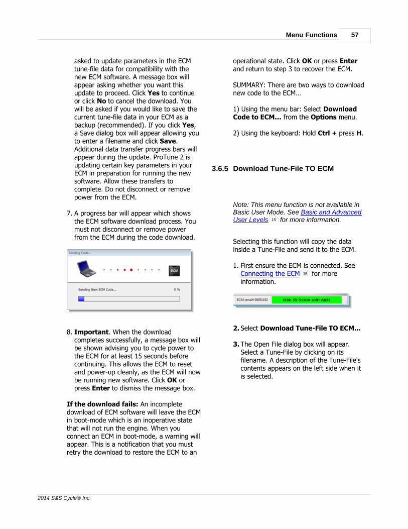
Menu Functions 57
2014 S&S Cycle® Inc.
asked to update parameters in the ECMtune-file data for compatibility with thenew ECM software. A message box willappear asking whether you want thisupdate to proceed. Click Yes to continueor click No to cancel the download. Youwill be asked if you would like to save thecurrent tune-file data in your ECM as abackup (recommended). If you click Yes,a Save dialog box will appear allowing youto enter a filename and click Save.Additional data transfer progress bars willappear during the update. ProTune 2 isupdating certain key parameters in yourECM in preparation for running the newsoftware. Allow these transfers tocomplete. Do not disconnect or removepower from the ECM.
7. A progress bar will appear which showsthe ECM software download process. Youmust not disconnect or remove powerfrom the ECM during the code download.
8. Important. When the downloadcompletes successfully, a message box willbe shown advising you to cycle power tothe ECM for at least 15 seconds beforecontinuing. This allows the ECM to resetand power-up cleanly, as the ECM will nowbe running new software. Click OK orpress Enter to dismiss the message box.
If the download fails: An incompletedownload of ECM software will leave the ECMin boot-mode which is an inoperative statethat will not run the engine. When youconnect an ECM in boot-mode, a warning willappear. This is a notification that you mustretry the download to restore the ECM to an
operational state. Click OK or press Enterand return to step 3 to recover the ECM.
SUMMARY: There are two ways to downloadnew code to the ECM…
1) Using the menu bar: Select DownloadCode to ECM… from the Options menu.
2) Using the keyboard: Hold Ctrl + press H.
3.6.5 Download Tune-File TO ECM
Note: This menu function is not available inBasic User Mode. See Basic and AdvancedUser Levels for more information.
Selecting this function will copy the datainside a Tune-File and send it to the ECM.
1. First ensure the ECM is connected. See Connecting the ECM for moreinformation.
2. Select Download Tune-File TO ECM...
3. The Open File dialog box will appear.Select a Tune-File by clicking on itsfilename. A description of the Tune-File'scontents appears on the left side when itis selected.
15
15

S&S Cycle® ProTune 258
2014 S&S Cycle® Inc.
4. Click Open.
5. If the tune-file you have selected ispotentially incompatible with your ECM, amessage box will appear asking you toconfirm your choice. If you are certain thatyou want to use the selected tune-file,click Yes to continue. Otherwise, click Noand return to step 2 to select a compatibletune-file (the tune-file description in theOpen File dialog box will help you to dothis).
6. For certain combinations of tune-file andECM, ProTune 2 will resolveincompatibilities by adjusting the tune-filedata before it is sent to the ECM. Thetune-file update dialog box will appear.Select the model year of your vehicle fromthe drop-down list options and click OK orpress Enter to continue with thedownload. Click Cancel or press Esc toquit the tune-file download.
7. For tune-file updates, you will be asked ifyou would like to save the current tune-filedata in your ECM as a backup(recommended). If you click Yes, a Savedialog box will appear allowing you toenter a filename and click Save.Additional data transfer progress bars willappear during the update. Allow thesetransfers to complete. Do not disconnector remove power from the ECM.
8. The Tune-File will now download to theECM. A progress bar indicates the amountof data left to send. Do not disconnect thecommunications cable or switch off power
to the ECM during this stage.
9. If the download fails to complete, verifythat the ECM still has power (vehicleignition on) and the cables are firmlyconnected. Retry the download. If thedownload continues to fail, try resettingthe ECM by cycling the power (vehicleignition off for 15 seconds, then switchback on).
10.Important: When the downloadcompletes successfully, a message box willbe shown advising you to cycle power tothe ECM for at least 15 seconds beforecontinuing. This allows the ECM to resetand power-up cleanly, as the Tune-Filedownload may have updated criticaloperating parameters. Click OK or pressEnter to dismiss the message box.
SUMMARY: There are two ways to downloada Tune-File to the ECM…
1) Using the menu bar: Select DownloadTune-File TO ECM… from the Optionsmenu.
2) Using the keyboard: Hold Ctrl + Shiftand press R.
3.6.6 Upload Tune-File FROM ECM
Note: This menu function is not available inBasic User Mode. See Basic and AdvancedUser Levels for more information.15

Menu Functions 59
2014 S&S Cycle® Inc.
Selecting this function will copy the datainside the ECM and store it on your computeras a Tune-File.
1. First ensure the ECM is connected. See Connecting the ECM for moreinformation.
2. Select Upload Tune-File FROM ECM…
3. The Save File dialog box will appear. Youcan either select an existing Tune-File tooverwrite by clicking on its filename orenter a new filename in the File Name boxto create a new Tune-File. A description ofthe Tune-File contents appears on the leftside when it is selected.
4. Click Save. The Tune-File will now beuploaded from the ECM. A progress barindicates the amount of data left to load.Do not disconnect the communicationscable or switch off power to the ECMduring this stage.
5. When the 'Transfer Complete' messageappears, click OK or press Enter. If theupload fails to complete, verify the ECMstill has power (vehicle ignition on) andthe cables are firmly connected. Retry theupload. If the upload continues to fail, tryresetting the ECM by cycling the power(vehicle ignition off for 15 seconds, thenswitch back on).
SUMMARY: There are two ways to upload aTune-File from the ECM…
1) Using the menu-bar: Select UploadTune-File FROM ECM… from the Optionsmenu.
2) Using the keyboard: Hold Ctrl + Shiftand press S.
3.6.7 Open Table from
Note: This menu function is not available inBasic User Mode. See Basic and AdvancedUser Levels for more information.
Select this function to load the current tablefrom a different data source (ECM or file).
1. Select Open Table from…
2. The Select Data Source dialog box willappear. The dialog box will list the currentactive data sources; i.e. the ECM if it isconnected, the demonstration data built
15
15

S&S Cycle® ProTune 260
2014 S&S Cycle® Inc.
into the software, and any calibration filesthat you accessed since starting thesoftware. To select a data source, click onit to highlight it and then click OK orpress Enter. You can also double-click onan item to select it. If you want to browsefor another calibration, select the 'Acalibration file not on this list' option.This will cause an Open File dialog box toappear. Select a calibration file from thisdialog box and click Open.
The current table will now be redisplayedwith the data from the selected data source.If the data source is the ECM, a progress barwill appear and the data may take a fewseconds to load.
SUMMARY: There are two ways to open thecurrent table from a different data source…
1) Using the menu bar: Select Open Tablefrom… from the Options menu.
2) Using the keyboard: Hold Ctrl + press O.
3.6.8 Save Table
Note: This menu function is not available inBasic User Mode. See Basic and AdvancedUser Levels for more information.
Select this function to save the current tableto the current data source. Doing this willoverwrite the table stored in the current data
source. If the current data source is theDemo Data file, a message will appear toinform you that the contents of this filecannot be modified. Click OK or press Enterto dismiss this message.
SUMMARY: There are two ways to save thecurrent table to the current data source…
1) Using the menu bar: Select Save Tablefrom the Options menu.
2) Using the keyboard: Hold Ctrl + press S.
3.6.9 Save Table To
Select this function to save the current tableto a different data source. Doing this willoverwrite the table stored in that datasource.
1. Select Save Table To…
2. The Select Data Source dialog box willappear. The dialog box will list the currentactive data sources; i.e. the ECM if it isconnected, the demonstration data builtinto the software, and any calibration filesthat you accessed since starting thesoftware. To select a data source, click onit to highlight it and then click OK orpress Enter. You can also double-click onan item to select it. If you want to browsefor another calibration, select the 'Acalibration file not on this list' option.This will cause an Open File dialog box toappear. Select a calibration file from thisdialog box and click Open.
15

Menu Functions 61
2014 S&S Cycle® Inc.
3. The current table will now be saved to theselected data source.
SUMMARY: There are three ways to save thecurrent table to a different data-source…
1) Using the tool bar: Click the Save->button:
2) Using the menu bar: Select Save TableTo… from the Options menu.
3) Using the keyboard: Hold Ctrl + press T.
3.6.10 Copy Calibration File
Note: This menu function is not available inBasic User Mode. See Basic and AdvancedUser Levels for more information.
Use this function if you want to makemodifications to a calibration file suppliedwith the software without altering theoriginal.
1. Select Copy Calibration File…
2. The Open File dialog box will appear.Select a file by clicking on its filename. Adescription of the files contents appearson the left side when it is selected.
3. The Save File dialog box will appear. Youcan either select an existing file tooverwrite by clicking on its file name, orenter a new filename in the File Name boxto create a new file. A description of thefiles contents appears on the left sidewhen it is selected.
4. The 'File copied' message will appear.Click OK or press Enter.
SUMMARY: There are two ways to copy anexisting calibration file…
1) Using the menu-bar: Select CopyCalibration File… from the Options menu.
2) Using the keyboard: Hold Ctrl + press I.
3.6.11 Test Outputs
The Test Outputs function allows you to drive
15
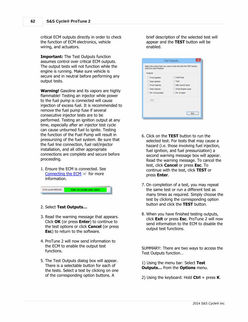
S&S Cycle® ProTune 262
2014 S&S Cycle® Inc.
critical ECM outputs directly in order to checkthe function of ECM electronics, vehiclewiring, and actuators.
Important: The Test Outputs functionassumes control over critical ECM outputs.The output tests will not function while theengine is running. Make sure vehicle issecure and in neutral before performing anyoutput tests.
Warning! Gasoline and its vapors are highlyflammable! Testing an injector while powerto the fuel pump is connected will causeinjection of excess fuel. It is recommended toremove the fuel pump fuse if severalconsecutive injector tests are to beperformed. Testing an ignition output at anytime, especially after an injector test cyclecan cause unburned fuel to ignite. Testingthe function of the Fuel Pump will result inpressurizing of the fuel system. Be sure thatthe fuel line connection, fuel rail/injectorinstallation, and all other appropriateconnections are complete and secure beforeproceeding.
1. Ensure the ECM is connected. See Connecting the ECM for moreinformation.
2. Select Test Outputs…
3. Read the warning message that appears.Click OK (or press Enter) to continue tothe test options or click Cancel (or pressEsc) to return to the software.
4. ProTune 2 will now send information tothe ECM to enable the output testfunctions.
5. The Test Outputs dialog box will appear.There is a selectable button for each ofthe tests. Select a test by clicking on oneof the corresponding option buttons. A
brief description of the selected test willappear and the TEST button will beenabled.
6. Click on the TEST button to run theselected test. For tests that may cause ahazard (i.e. those involving fuel injection,fuel ignition, and fuel pressurization) asecond warning message box will appear.Read the warning message. To cancel thetest, click Cancel or press Esc. Tocontinue with the test, click TEST orpress Enter.
7. On completion of a test, you may repeatthe same test or run a different test asmany times as required. Simply choose thetest by clicking the corresponding optionbutton and click the TEST button.
8. When you have finished testing outputs,click Exit or press Esc. ProTune 2 will nowsend information to the ECM to disable theoutput test functions.
SUMMARY: There are two ways to access theTest Outputs function…
1) Using the menu bar: Select TestOutputs… from the Options menu.
2) Using the keyboard: Hold Ctrl + press K.
15
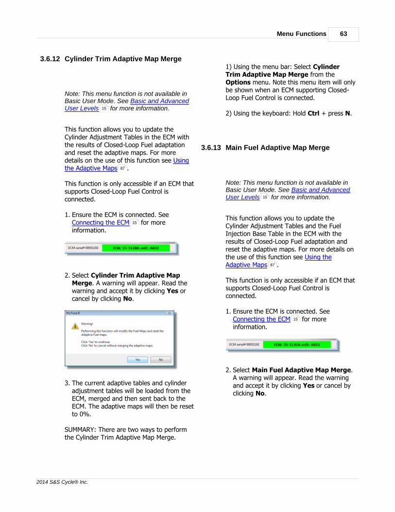
Menu Functions 63
2014 S&S Cycle® Inc.
3.6.12 Cylinder Trim Adaptive Map Merge
Note: This menu function is not available inBasic User Mode. See Basic and AdvancedUser Levels for more information.
This function allows you to update theCylinder Adjustment Tables in the ECM withthe results of Closed-Loop Fuel adaptationand reset the adaptive maps. For moredetails on the use of this function see Usingthe Adaptive Maps .
This function is only accessible if an ECM thatsupports Closed-Loop Fuel Control isconnected.
1. Ensure the ECM is connected. See Connecting the ECM for moreinformation.
2. Select Cylinder Trim Adaptive MapMerge. A warning will appear. Read thewarning and accept it by clicking Yes orcancel by clicking No.
3. The current adaptive tables and cylinderadjustment tables will be loaded from theECM, merged and then sent back to theECM. The adaptive maps will then be resetto 0%.
SUMMARY: There are two ways to performthe Cylinder Trim Adaptive Map Merge.
1) Using the menu bar: Select CylinderTrim Adaptive Map Merge from theOptions menu. Note this menu item will onlybe shown when an ECM supporting Closed-Loop Fuel Control is connected.
2) Using the keyboard: Hold Ctrl + press N.
3.6.13 Main Fuel Adaptive Map Merge
Note: This menu function is not available inBasic User Mode. See Basic and AdvancedUser Levels for more information.
This function allows you to update theCylinder Adjustment Tables and the FuelInjection Base Table in the ECM with theresults of Closed-Loop Fuel adaptation andreset the adaptive maps. For more details onthe use of this function see Using theAdaptive Maps .
This function is only accessible if an ECM thatsupports Closed-Loop Fuel Control isconnected.
1. Ensure the ECM is connected. See Connecting the ECM for moreinformation.
2. Select Main Fuel Adaptive Map Merge.A warning will appear. Read the warningand accept it by clicking Yes or cancel byclicking No.
15
87
15
15
87
15

S&S Cycle® ProTune 264
2014 S&S Cycle® Inc.
3. The current adaptive tables, cylinderadjustment tables and main fuel table willbe loaded from the ECM, merged and thensent back to the ECM. The adaptive mapswill then be reset to 0%.
SUMMARY: There are two ways to performthe Main Fuel Adaptive Map Merge.
1) Using the menu bar: Select Main FuelAdaptive Map Merge from the Optionsmenu. Note this menu item will only beshown when an ECM supporting Closed-LoopFuel Control is connected.
2) Using the keyboard: Hold Ctrl + press M.
3.6.14 Reset Adaptive Maps
Note: This menu function is not available inBasic User Mode. See Basic and AdvancedUser Levels for more information.
This function commands the ECM to reset (to0%) its adaptive fuel maps and the adaptiveignition map. The adaptive fuel trim mapscontain values that the ECM learns basedupon the results of Closed-Loop Fuel Control.The adaptive ignition map contains long termignition timing adjustments due to engineknock control. For more details on thesesubjects see The Closed-Loop Fuel ControlSystem and The Knock (AdaptiveIgnition) Control System .
This function is only accessible if an ECM that
supports Closed-Loop Fuel Control or KnockControl is connected.
1. Ensure the ECM is connected. See Connecting the ECM for moreinformation.
2. Select Reset Adaptive Maps. A warningwill appear. Read the warning and acceptit by clicking Yes or cancel by clicking No.
3. The adaptive maps will now be reset.Click OK (or press Enter) to continue.
SUMMARY: There are two ways to Reset theAdaptive Maps…
1) Using the menu bar: Select ResetAdaptive Maps from the Options menu.Note this menu item will only be shown whenan ECM supporting Closed-Loop Fuel Controlor Knock Control is connected.
2) Using the keyboard: Hold Ctrl + press R.
3.6.15 Clear Historic Diagnostic Trouble Codes
Select this function in order to clear the listof historic diagnostic trouble-codes in yourECM. To view the current and historic ECMdiagnostic trouble codes, use the DiagnosticTrouble Codes function.
1. Ensure the ECM is connected. See
15
83
88
15
33

Menu Functions 65
2014 S&S Cycle® Inc.
Connecting the ECM for moreinformation.
2. Select Clear Historic DiagnosticTrouble Codes.
3. A message will appear telling you that thetrouble-codes have been reset. Click OK orpress Enter.
SUMMARY: There are three ways to clear thehistoric diagnostic trouble-codes in the ECM…
1) Using the menu bar: Select ClearHistoric Diagnostic Trouble Codes fromthe Options menu.
2) Using the keyboard: Hold Ctrl + press E.
3) Using the DTCs dialog box. See DiagnosticTrouble Codes for details.
3.7 Help Menu
3.7.1 Help Topics
Select this function to display this helpdocument.
SUMMARY: There are two ways to accessthis help system…
1) Using the menu bar: Select HelpTopics… from the Help menu.
2) Using the keyboard: Press F1.
3.7.2 About ProTune II
Select this function to show the softwareversion and installation details of your copyof ProTune 2. This information may berequired for customer support. Click OK orpress Enter to dismiss the "About ProTune2" dialog box when finished.
SUMMARY: There are two ways to show the'About' dialog box…
1) Using the menu bar: Select AboutProTune II… from the Help menu.
2) Using the keyboard: Hold the Ctrl + pressB.
4 The Fuel and Ignition Systems
4.1 The Fuel Injection System
The diagram below describes the fuel systemof the S&S Cycle® ECM:
15
33

S&S Cycle® ProTune 266
2014 S&S Cycle® Inc.
The Base Fuel Injection Table provides theinitial fuel injector pulse width value inmilliseconds (ms) as a function of enginespeed and throttle position (with a resolutionof 32 throttle sites). The fuel injector pulsewidth specifies how long the fuel injector isopen per fuel injection event. The longer thepulse width, the more fuel that is injected.
The Engine Temperature Fuel Compensationand Air Temperature Fuel Compensationadjust the fuel delivery as a function oftemperature. They are only accessible inAdvanced Mode (see Basic and AdvancedUser Levels for details of switchingmodes). Each table adds a percentage of theinput fuel injector pulse width as a functionof temperature.
Once other non-adjustable compensationsare included in the calculation, acompensation value is added for eachcylinder. These compensation tables are the Front Cylinder Fuel Adjustment Table andthe Rear Cylinder Fuel Adjustment Table.These compensation tables allow the fueldelivery to be adjusted for each cylinder as afunction of engine speed and throttle position(with a resolution of 16 throttle sites). Theresult of each cylinder compensationproduces the final injection pulse width foreach cylinder.
Examples of compensation factors:
If a compensation value at a particulartemperature is 0% and the input value is4ms, the output of the compensation tablewould be 4ms + (0% of 4ms) = 4ms (nochange).
If the compensation value is +100% and theinput value is 4ms, the output of thecompensation table would be 4ms + (100%of 4ms) = 8ms (double the fuel).
If the compensation value is -100% and theinput value is 4ms, the output of thecompensation table would be 4ms – (100%of 4ms) = 0ms (zero fuel).
4.2 The Ignition Timing System
The diagram below describes the ignitiontiming system of the S&S Cycle® ECM:
The Base Ignition Timing Table provides theinitial ignition timing as a function of enginespeed and throttle position (with a 16throttle site resolution). This timing value isthe Ignition Advance measured in degreesbefore TDC (Top Dead Center position). Apositive number for the ignition advance will
15

The Fuel and Ignition Systems 67
2014 S&S Cycle® Inc.
mean that the spark is fired before the pistonreaches Top Dead Center during thecompression stroke. A zero ignition advancemeans that the spark will be fired at the TopDead Center position. A negative number forthe ignition advance means that the sparkwill fire after the piston has reached TopDead Center.
The Engine Temperature IgnitionCompensation and Air Temperature IgnitionCompensation tables adjust the ignitionadvance as a function of temperature. Theyare only accessible in Advanced Mode (see Basic and Advanced User Levels fordetails of switching modes). Each table addsan amount of ignition advance which varieswith temperature.
After other (non-adjustable) compensationshave been added, the result is the FinalIgnition Advance value which is used to firethe spark.
5 Tuning in Basic Mode
5.1 Viewing and Tuning Tables
The current table is displayed as athree-dimensional graph with Engine Speedin RPM along the horizontal (x) axis, ThrottlePosition in percent of wide open throttlealong the depth (z) axis and table valuealong the upward (y) axis. For an explanationof what each table contains and does, see The Fuel Injection System and TheIgnition Timing System .
The graph is shaded according to the valueat each point in the table. The meaning ofthe shading is illustrated in the color key stripon the right of the graph.
Also shown on the graph are the Cursor(bright blue upside-down pyramid) and the Current Selected Area (white rectangularboundary).
The Cursor shows the center of the zone ofthe table that you are currently editing.Above the Cursor is the Cursor Pop-upWindow (this may be switched off, seeSwitch On/Off Map Cursor Pop-up fordetails). The Cursor Pop-up Windowshows the RPM, throttle percentage andtuned table value at the point of the Cursor.
You can move the cursor around the table tothe next intersection of the graph lines(zone) by doing one of the following:
· Clicking and dragging the RPM orThrottle Sliders at the bottom of thescreen. Dragging the RPM Slider left willmove to a lower Engine Speed position(moves cursor left). Dragging it right willmove to a higher Engine Speed position(moves cursor right). Dragging the Throttle Slider left will move to a lower(closing) throttle position (moves cursordown). Dragging it right will move to ahigher (opening) throttle position (movescursor up).
15
65
66
28

S&S Cycle® ProTune 268
2014 S&S Cycle® Inc.
· When pressing the Arrow keys, the LeftArrow key will move to a lower EngineSpeed position (moves the cursor left) andthe Right Arrow key will move to ahigher engine speed position (moves thecursor right). The Up Arrow key will moveto a higher (opening) throttle position(moves the cursor up) and the DownArrow key will move to a lower (closing)throttle position (moves the cursor down).
· By clicking on an area of the graph. Thiswill move the cursor to the nearest enginespeed and throttle zone (intersection of thegraph lines).
As you move the Cursor the CurrentSelected Area moves with it. The CurrentSelected Area determines how much of thetable is affected when you apply tuning tothat zone of the table.
You can increase and decrease the size ofthe Current Selected Area by doing one ofthe following:
· Moving the Range Knob located in thelower center of the screen. Click on thecircular knob indent and drag the mouseclockwise or counter-clockwise to adjust itsposition. The Range is a number from 1(very small Current Selected Area) to 10(very large Current Selected Area).
· By using the Arrow keys and Shift key.Holding Shift and pressing Left Arrow orDown Arrow will increase the range by 1.Holding Shift and pressing Right Arrowor Up Arrow will decrease the range by1.
Once you have set the Current SelectedArea to the portion of the table that youwant to tune, you can then adjust its values.You can apply tuning to the CurrentSelected Area by doing one of thefollowing:
· Move the Tuning Knob (left of the
Range Knob) at the bottom of thescreen. Click on the circular knob indentand drag the mouse clockwise or
counter-clockwise to adjust its position.
· Use the Page Up and Page Down keys.Pressing Page Up will increase the tuningby 1% and Page Down will decrease thetuning by 1%. Holding the Shift key andpressing Page Up will increase the tuningby 5% and Shift+Page Down willdecrease tuning by 5%. Holding the Ctrlkey and pressing Page Up will increasethe tuning by 25% and pressing Ctrl+Page Down will decrease the tuning by25%.
· Use the Tuning Buttons (left of theTuning Knob) to select the size of thetuning increment by clicking either the Coarse (25%), Medium (5%), or Fine(1%) buttons. Click on the up-arrow to

Tuning in Basic Mode 69
2014 S&S Cycle® Inc.
increase the tuning. Click on thedown-arrow to decrease the tuning.Clicking and holding on one of the arrowswill continuously increase or decrease.
The effect of tuning the Current SelectedArea will be applied fully at the cursorposition and less towards the boundary ofthe selected area. See the following exampleof applying 100% to a flat section of a table:
The 100% tuning is applied fully at thecursor position and curves away towards theboundary of the selected area. This enablesyou to make smooth changes to a tablewithout introducing sudden step changesthat may cause poor engine response .
When tuning is applied to two zones of atable that are next to each other and theselected areas overlap, the tuning effect isblended (additively) between the two zones.See the example below:
In this example, three RPM zones next toeach other are tuned and overlap.
The tuning range is applied differentlydepending on the table you are tuning:
· The Base Fuel Injection Table. A valueis added corresponding to the tuningpercentage of original value. For example,if the cursor is at 8 ms, applying a tuningof 100% will double the fuel at the cursorposition to 16 ms. If the tuning was set to-50% this would halve the fuel at thecursor position to 4 ms.
· The Base Ignition Timing Table. Atuning of +30° corresponds to adding 30degrees of ignition advance (moving theignition point 30 degrees more before TopDead Center). A tuning of -30°corresponds to subtracting 30 degrees ofignition advance (moving the ignition point30 degrees towards or after Top DeadCenter).
· The Front Cylinder Adjustment Tableand Rear Cylinder Adjustment Table.The tuning percentage value is added tothe table's percentage value. For example,if the cursor is at 10% and the tuning knobis set to +10%, the tuned value will be20%. If the cursor is at 10% and thetuning knob is set to -10%, the tunedvalue will be 0%.
This tuning system ensures that you canmake safe and smooth changes to theoriginal table values. To make changes that

S&S Cycle® ProTune 270
2014 S&S Cycle® Inc.
are more detailed to the tables, you mustswitch to Advanced Mode (see Select UserLevel… for more details).
To undo a change that you have made to thetable, select Undo from the Edit menu.
Once you have made the changes yourequire to a table, you can save it byselecting Save Table To… from theOptions menu. Once saved, the tuningapplied to a table is reset so that the tunedvalues now become the original table valuesand can be tuned further.
5.2 Live-Tune in Basic Mode
Live-Tune mode allows you to make a directconnection with the ECM so that any tuningyou apply to the current ECM table takesimmediate effect in the ECM. Live-Tuning canbe very useful as you can run the engine indifferent throttle and RPM zones and seeinstantly how your tuning effects the engineperformance.
Tuning in Live-Tune mode is performed thesame way as tuning in normal mode. Seethe Viewing and Tuning Tables page ofthis section for more information on how totune.
To tune in Live-Tune mode you must edit atable that is loaded from the ECM. To dothis:
1. First ensure the ECM is connected. See Connecting the ECM for moreinformation.
2. Load the table that you want to Live-Tunefrom the ECM. Select the table using thetool-bar or the View menu. Select the
ECM as the current data source using the Current Data Source Selector at thetop of the screen or from the View menu.
3. You now need to activate Live-Tune modeby selecting Live-Tune Mode On/Offfrom the Edit menu or click the Live!button on the toolbar.
4. ProTune 2 will automatically send newcontrol information to the ECM andLive-Tune mode will become active.Tuning the table will now directly effectthe tuning in the ECM.
Note that during Live-Tune, many of theprogram's functions are disabled. You mustdeactivate Live-Tune mode in order to returnto normal mode.
When Live-Tune mode is active, a second(black) cursor will appear on the 3D-graph:
This is the Live Cursor and shows you theposition in the table that the engine iscurrently running. As you increase throttleposition and/or engine speed, the LiveCursor will move across the table. You arefree to move the blue Cursor around thetable so that you can tune any part of thetable. If you tune a part of the table whichcontains the Live Cursor, you will be able todetect this change in your engine's runningbehavior.
In Live-Tune mode, the Cursor Locationsection of the information bar now reflectsthe Live Cursor position and tuning at that
54
25
60
67
15
29
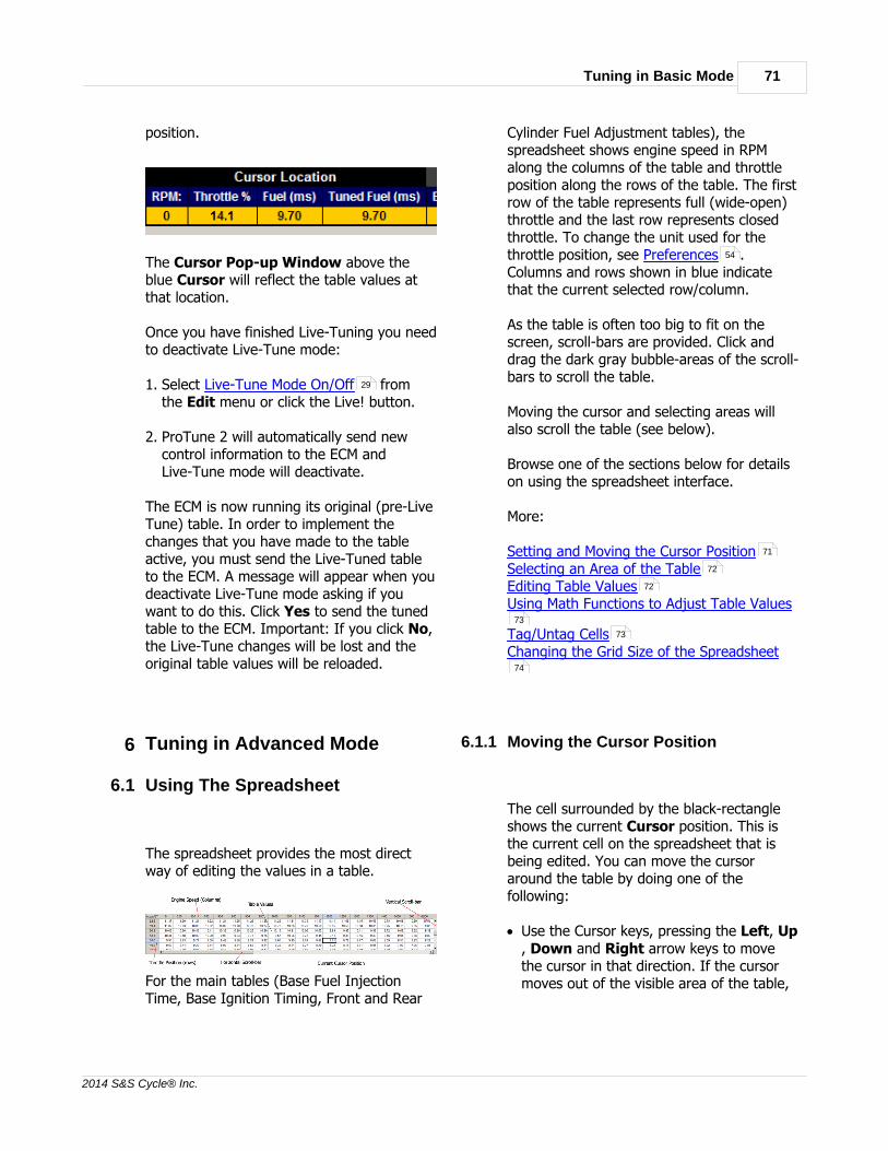
Tuning in Basic Mode 71
2014 S&S Cycle® Inc.
position.
The Cursor Pop-up Window above theblue Cursor will reflect the table values atthat location.
Once you have finished Live-Tuning you needto deactivate Live-Tune mode:
1. Select Live-Tune Mode On/Off fromthe Edit menu or click the Live! button.
2. ProTune 2 will automatically send newcontrol information to the ECM andLive-Tune mode will deactivate.
The ECM is now running its original (pre-LiveTune) table. In order to implement thechanges that you have made to the tableactive, you must send the Live-Tuned tableto the ECM. A message will appear when youdeactivate Live-Tune mode asking if youwant to do this. Click Yes to send the tunedtable to the ECM. Important: If you click No,the Live-Tune changes will be lost and theoriginal table values will be reloaded.
6 Tuning in Advanced Mode
6.1 Using The Spreadsheet
The spreadsheet provides the most directway of editing the values in a table.
For the main tables (Base Fuel InjectionTime, Base Ignition Timing, Front and Rear
Cylinder Fuel Adjustment tables), thespreadsheet shows engine speed in RPMalong the columns of the table and throttleposition along the rows of the table. The firstrow of the table represents full (wide-open)throttle and the last row represents closedthrottle. To change the unit used for thethrottle position, see Preferences .Columns and rows shown in blue indicatethat the current selected row/column.
As the table is often too big to fit on thescreen, scroll-bars are provided. Click anddrag the dark gray bubble-areas of the scroll-bars to scroll the table.
Moving the cursor and selecting areas willalso scroll the table (see below).
Browse one of the sections below for detailson using the spreadsheet interface.
More:
Setting and Moving the Cursor PositionSelecting an Area of the TableEditing Table ValuesUsing Math Functions to Adjust Table Values
Tag/Untag CellsChanging the Grid Size of the Spreadsheet
6.1.1 Moving the Cursor Position
The cell surrounded by the black-rectangleshows the current Cursor position. This isthe current cell on the spreadsheet that isbeing edited. You can move the cursoraround the table by doing one of thefollowing:
· Use the Cursor keys, pressing the Left, Up, Down and Right arrow keys to movethe cursor in that direction. If the cursormoves out of the visible area of the table,
29
54
71
72
72
73
73
74

S&S Cycle® ProTune 272
2014 S&S Cycle® Inc.
the table will scroll automatically to keep itvisible.
· Click on a cell in the spreadsheet, this willmove the cursor to that cell.
· Click on a location in the 3D-graph, thecursor on the spreadsheet will move to thesame location.
6.1.2 Selecting an Area of the Table
You can use the spreadsheet to select anarea of cells in the table. The black bordershows the extent of the selected area.Selected cells, columns, and rows are shownin blue with the cursor position shown inwhite.
You can select an area of the table using oneof the following methods:
· Hold the Shift key and press the Cursorkeys Left, Right, Down, or Up to expandor shrink the selected area in thatdirection. If the cursor moves outside ofthe visible area of the table, the table willscroll to keep it visible.
· Click on a cell and drag the mouse toselect a region. The cell that you click onwill form one corner of the selected areawith the opposite corner being determinedby the mouse position.
· Clicking on a column or row header toselect that column/row. Clicking anddragging across the column or row
headers will select multiple rows/columns.
· Hold the Ctrl key and press A to select theentire table. You can also access thisfunction by right-clicking on a cell in thespreadsheet and selecting Select All fromthe menu.
· You can click and drag the mouse on the3D-graph to select an area of the graph,this will also select the matching area onthe spreadsheet.
To cancel the current selected area, pressthe Esc key, or move the cursor outside ofthe selected area. You can also right-click onthe selected area of the spreadsheet andpick Deselect from the menu.
6.1.3 Editing Table Values
Once you have selected a cell or an area ofcells to edit, you can then adjust the valuesof those cells. To enter a new value for thecurrent cell or current selected area, type inthe new value and press Enter. Pressing anumber key will automatically start editingthe cursor cell, use the number keys andback-space key to edit the value. Press Escto cancel the editing without adjusting thevalue or press Enter to accept the newvalue. You can also edit a cell by doubleclicking on it and end editing by pressing oneof the cursor keys to move to the next cell.
When you enter a new value, that value willbe set in the cursor cell and any selectedarea. If the number is outside of the range ofthe table, it will be set to the nearest valueallowed.
You can also adjust the value in the cursorcell or current selected area by using the Page Up and Page Down keys. Page Upwill add a x1 increment to the selected area(0.01ms for the Fuel table, 0.1 degree of

Tuning in Advanced Mode 73
2014 S&S Cycle® Inc.
advance for the Ignition table, 1 % forcylinder adjustment tables). Page Down willsubtract a x1 decrement from the selectedcells. Holding the Shift key while pressingPage Up or Page Down will increment/decrement the selected cells by a x10amount (0.1 ms for the Fuel table, 1 degreeof advance for the Ignition table). Theincrement/decrement while holding the Shiftkey for the cylinder adjustment tables is +/-5 %. Holding the Ctrl key while pressingPage Up or Page Down will increment/decrement the selected cells by a x100 unitamount (1 ms for the Fuel table, 10 degreesof advance for the Ignition table). Theincrement/decrement while holding the Ctrlkey for the cylinder adjustment tables is +/-25 %. These functions can also be accessedvia the mouse by right clicking on the cursorcell or selected area and selecting one of the Increment or Decrement items from themenu. You can also right-click any part of the3D graph to access this menu.
6.1.4 Using Math Functions to Edit Table Values
ProTune 2 supports the use of basic mathfunctions (add, subtract, multiply and divide)to edit cell values. To apply a math functionto the cursor cell or selected area:
· To add a value to the selected cells, type + followed by the value to add and press
Enter. For example +2 <Enter>.
· To subtract a value from the selected cell,type - followed by the value to subtractand press Enter. For example -2 <Enter>will subtract 2 from the value. To set thevalue as a negative number rather thanperforming a subtraction, type = followedby the negative number. For example =-2<Enter> will set the value as -2.
· To multiply the selected cells by a value,type * followed by the value to multiplyand press Enter. For example *2<enter>.
· To divide the selected cells by a value,type / followed by the value to divide byand press Enter. For example /2<enter>.
6.1.5 Tag/Untag Cells
Cells on the table can be tagged (marked)for later reference. When a cell is tagged, itappears with a flag symbol next to it on thespreadsheet and an upside down trianglemarker on the graph.
Cells can be tagged in three ways:
· Manually tagged at user discretion, thesetags will appear in purple.
· Automatically tagged by ProTune 2 duringLive-Tune to show the cells that the enginehas visited the cell during running. Thesetags will appear in purple.
· Automatically tagged by ProTune 2 during

S&S Cycle® ProTune 274
2014 S&S Cycle® Inc.
Live-Tune to show that a cell value hasbeen adjusted. These tags will appear ingreen.
Cells and areas of cells can be manuallytagged or untagged by moving the cursor tothe required cell (or selecting an area ofcells) and doing one of the following:
· Pressing F9.
· Right-clicking on the selected cells andpicking Tag/Untag Cells from the menu.
· Selecting Tag/Untag Cells from the Editmenu.
The feature that automatically tags cellsduring Live-Tune can be toggled on/off byselecting Switch On/Off Auto-Tagging inLiveTune from the Edit menu or bypressing Shift+F7.
All tags present in the current table can becleared by selecting Clear All Markers fromthe Edit menu or by pressing F3.
6.1.6 Grid Size of the Spreadsheet
You can change the size of the cells and thevalues inside the cells by changing the gridsize of the spreadsheet. There are threemodes: small, normal and large. The defaultmode is 'normal'.
To change the size, select Cycle Grid Sizefrom the Edit menu or hold the Shift keyand press F6. This will move from 'normal'mode to 'large' mode.
Select again to move from 'large' mode to'small' mode. Select once more to move from'small' mode back to 'normal' mode.
6.2 Using the 3D Graph
The 3D graph displays the current table as athree-dimensional surface plot with EngineSpeed in RPM along the horizontal (x) axis,Throttle Position along the depth (z) axis andtable value along the upward (y) axis. Tochange the unit used for the throttle position,see Preferences .
The graph is shaded according to the valueat each point in the table. The meaning ofthe shading is illustrated in the color key strip(right of the graph) by showing how thecolors map onto the table values.
Also shown on the graph is the cursor (brightblue upside-down pyramid). A selected areaof cells is shown on the graph by a whiterectangular boundary.
Above the cursor is the cursor pop-upwindow (this may be switched off, see SwitchOn/Off Map Cursor Pop-up for details).The cursor pop-up window shows the RPM,throttle position and tuned table value at thepoint of the cursor.
54
28
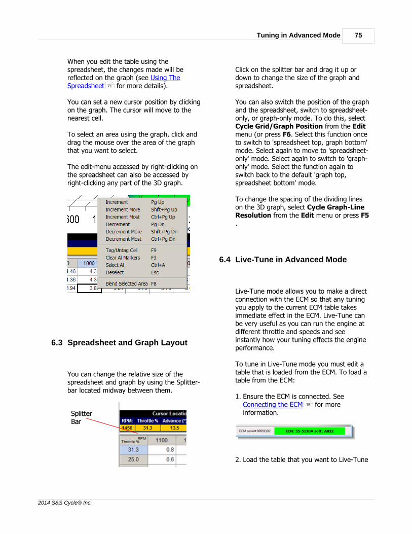
Tuning in Advanced Mode 75
2014 S&S Cycle® Inc.
When you edit the table using thespreadsheet, the changes made will bereflected on the graph (see Using TheSpreadsheet for more details).
You can set a new cursor position by clickingon the graph. The cursor will move to thenearest cell.
To select an area using the graph, click anddrag the mouse over the area of the graphthat you want to select.
The edit-menu accessed by right-clicking onthe spreadsheet can also be accessed byright-clicking any part of the 3D graph.
6.3 Spreadsheet and Graph Layout
You can change the relative size of thespreadsheet and graph by using the Splitter-bar located midway between them.
Click on the splitter bar and drag it up ordown to change the size of the graph andspreadsheet.
You can also switch the position of the graphand the spreadsheet, switch to spreadsheet-only, or graph-only mode. To do this, select Cycle Grid/Graph Position from the Editmenu (or press F6. Select this function onceto switch to 'spreadsheet top, graph bottom'mode. Select again to move to 'spreadsheet-only' mode. Select again to switch to 'graph-only' mode. Select the function again toswitch back to the default 'graph top,spreadsheet bottom' mode.
To change the spacing of the dividing lineson the 3D graph, select Cycle Graph-LineResolution from the Edit menu or press F5.
6.4 Live-Tune in Advanced Mode
Live-Tune mode allows you to make a directconnection with the ECM so that any tuningyou apply to the current ECM table takesimmediate effect in the ECM. Live-Tune canbe very useful as you can run the engine atdifferent throttle and speeds and seeinstantly how your tuning effects the engineperformance.
To tune in Live-Tune mode you must edit atable that is loaded from the ECM. To load atable from the ECM:
1. Ensure the ECM is connected. See Connecting the ECM for moreinformation.
2. Load the table that you want to Live-Tune
71
15

S&S Cycle® ProTune 276
2014 S&S Cycle® Inc.
from the ECM. Select the table using thetool-bar or the View menu. Select theECM as the current data source using theCurrent Data Source Selector at the top ofthe screen or from the View menu.
Browse the following sections for informationon how to Live-Tune.
More:
Activating Live-Tune ModeTuning in Live-Tune ModeDeactivating Live-Tune Mode
6.4.1 Activating Live-Tune Mode
To activate Live-Tune mode:
1. Select Live-Tune Mode On/Off from theEdit menu or click the Live! button on thetoolbar.
2. ProTune 2 will automatically send newcontrol information to the ECM and Live-Tune mode will become active. Tuning thetable will now directly effect the tuning inthe ECM.
Note that during Live-Tune, many of theprogram's functions are disabled. You mustdeactivate Live-Tune mode to return tonormal mode.
6.4.2 Tuning in Live-Tune Mode
When Live-Tune mode is active the TuningKnob will appear to the left of thespreadsheet.
Move the editing cursor around the tableusing the Cursor keys or by clicking onareas of the graph (see Using TheSpreadsheet and Using the 3D Graphfor more details). To tune the cell at thecursor position, click on the indent of the Tuning Knob and drag the mouse clockwiseor counter-clockwise to adjust its position.You can also use the Page Up and PageDown keys to increment (page up) anddecrement (page down) the cell value.Holding the Shift key while pressing PageUp and Page Down results in a largeradjustment. Holding the Ctrl key whilepressing Page Up and Page Down resultsin the largest adjustment.
The tuning adjustment is applied differentlydepending on the table that you are tuning:
· The Base Fuel Injection Table. A value isadded corresponding to the tuningpercentage of original value. For example,if the cursor is at 8 ms, applying a tuningof 100% will double the fuel at the cursorposition to 16 ms. If the tuning was set to-50% this would halve the fuel at thecursor position to 4 ms.
· The Base Ignition Timing Table. A tuningof +30° corresponds to adding 30 degreesof ignition advance (moving the ignitionpoint 30 degrees more before Top DeadCenter). A tuning of -30° corresponds tosubtracting 30 degrees of ignition advance(moving the ignition point 30 degrees
76
76
77
71 74

Tuning in Advanced Mode 77
2014 S&S Cycle® Inc.
towards or past Top Dead Center).
· The Front Cylinder Adjustment Table andRear Cylinder Adjustment Table. Thetuning percentage value is added to thetables percentage value. For example, ifthe cursor is at 10% and the tuning knobis set to +10%, the tuned value will be20%. If the cursor is at 10% and thetuning knob is set to -10%, the tunedvalue will be 0%.
Tuning a cell will result in a green tag markerbeing placed at that cell. This marker showsthe cells that you have adjusted during Live-Tuning.
While Live-Tune mode is active, a second(black) cursor is shown on the 3D-graph:
This is the Live Cursor that shows you theposition in the table that the engine iscurrently running at. As you increase throttleposition and/or engine speed, the LiveCursor will move across the table. You arefree to move the blue Cursor around thetable so that you can tune any part of thetable. If you tune a part of the table whichcontains the Live Cursor, you will be able todetect this change in your engine's runningbehavior.
In Live-Tune mode, the Cursor Locationsection of the information bar now reflectsthe Live Cursor position and tuning at that
position.
The Cursor Pop-up Window above the blueCursor will reflect the table values at thatlocation.
As you Live-Tune, purple tags will be left atthe cells that the engine has visited duringLive-Tuning. To switch off this feature, see Switch On/Off Auto-Tagging in LiveTune .
6.4.3 Deactivating Live-Tune Mode
Once you have finished Live-Tuning you needto manually deactivate Live-Tune mode:
1. Select Live-Tune Mode On/Off fromthe Edit menu or click the Live! button.
2. ProTune 2 will automatically send newcontrol information to the ECM and Live-Tune mode will deactivate.
The ECM is now running its original (pre-LiveTune) table. In order to implement thechanges that you have made to the table,you must send the Live-Tuned table to theECM. A message will appear when youdeactivate Live-Tune mode asking whetheryou want to do this. Click Yes to send thetuned table to the ECM.
29
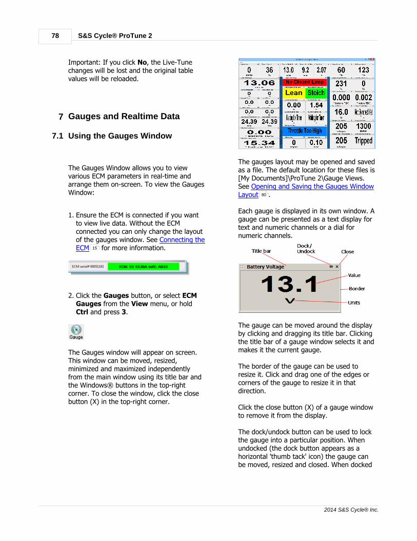
S&S Cycle® ProTune 278
2014 S&S Cycle® Inc.
Important: If you click No, the Live-Tunechanges will be lost and the original tablevalues will be reloaded.
7 Gauges and Realtime Data
7.1 Using the Gauges Window
The Gauges Window allows you to viewvarious ECM parameters in real-time andarrange them on-screen. To view the GaugesWindow:
1. Ensure the ECM is connected if you wantto view live data. Without the ECMconnected you can only change the layoutof the gauges window. See Connecting theECM for more information.
2. Click the Gauges button, or select ECMGauges from the View menu, or holdCtrl and press 3.
The Gauges window will appear on screen.This window can be moved, resized,minimized and maximized independentlyfrom the main window using its title bar andthe Windows® buttons in the top-rightcorner. To close the window, click the closebutton (X) in the top-right corner.
The gauges layout may be opened and savedas a file. The default location for these files is[My Documents]\ProTune 2\Gauge Views.See Opening and Saving the Gauges WindowLayout .
Each gauge is displayed in its own window. Agauge can be presented as a text display fortext and numeric channels or a dial fornumeric channels.
The gauge can be moved around the displayby clicking and dragging its title bar. Clickingthe title bar of a gauge window selects it andmakes it the current gauge.
The border of the gauge can be used toresize it. Click and drag one of the edges orcorners of the gauge to resize it in thatdirection.
Click the close button (X) of a gauge windowto remove it from the display.
The dock/undock button can be used to lockthe gauge into a particular position. Whenundocked (the dock button appears as ahorizontal 'thumb tack' icon) the gauge canbe moved, resized and closed. When docked
15
80

Gauges and Realtime Data 79
2014 S&S Cycle® Inc.
(the dock button appears as a vertical 'thumbtack' icon), the gauge is fixed into positionand the close button and resizing borderdisappear. Docked gauges can make forneater displays as well as preventingaccidental moving, resizing, and closing ofgauges. Click on the button to togglebetween its docked and undocked state.
Some gauges will have shaded backgroundcolors according to their state. The 'TargetClosed-Loop', 'Front Cylinder Closed-Loop'and 'Rear Cylinder Closed-Loop' gauges areshaded to match the options on the 'TargetClosed-Loop Fuel Map'.
Input gauges will flash red when the ECMdetects that the input value is outside of thevalid range. The title of the gauge willappear with an exclamation mark (!). Whenin this state, the gauge may show the defaultvalue that the ECM will use for this input (inthe example shown below, the enginetemperature from the sensor is outside ofvalid range and the ECM is using 100 °F as adefault value for this input).
Hovering the mouse cursor over a gauge willcause a pop-up to appear that gives yousome basic information about the channelbeing displayed. Right-clicking on the gaugewill bring up an information box with moredetailed information.
More:
To Add a Dial or Text Gauge…To Remove a Gauge…Always On Top settingSaving the Gauges Window Layout
7.1.1 To Add a Dial or Text Gauge
Go to the View menu of the GaugesWindow and select Add… The Add Gaugedialog box will be displayed.
Choose a channel from the list by clicking onit. When you select a channel, a descriptionappears in the description box on the rightside. If the channel is numeric (numberbased) the display style drop-down list willallow you to choose between a "Normal"display and a "Dial" display. Text-basedchannels can only be displayed with "Normal"displays.
To add the selected channel, click OK orpress Enter. If you do not wish to add thechannel, click Cancel or press Esc.
If a channel is selected, the new gaugewindow will now appear on screen and canbe repositioned and resized as required.
7.1.2 To Remove a Gauge
To remove an undocked (floating) gaugewindow from the display, either click on itsclose (X) button or select it by clicking on its
79
79
80
80

S&S Cycle® ProTune 280
2014 S&S Cycle® Inc.
title bar and select Remove from the Viewmenu of the Gauges Window.
7.1.3 Always On Top setting
By default, the gauges window is set so thatit will always appear on top of otherwindows. To change this so that the GaugesWindow can be moved to the background,click on the Always on Top menu item inthe View menu of the Gauges Window. Thiswill remove the check mark from this menuitem and you can now move the GaugesWindow to the background. Click on themenu item again to reset the Always onTop property.
7.1.4 Opening\Saving the Gauges Window Layout
To open a layout from file, select OpenLayout from the View menu of the GaugesWindow.
When you have modified the Gauges Displayand attempt to close it, ProTune 2 will askyou whether you want to save your changes.Click Cancel to return to the GaugesDisplays. Click Yes to save the currentdisplay state or click No if you do not wantto save your changes.
To save the display layout manually, select Save Layout from the View menu of theGauges Window.
To save the display layout to a specificfilename, select Save Layout As from the
View menu of the Gauges Window.
7.2 The Engine Data Area
When the ECM is connected, the Engine Datasection of the information bar will bedisplayed in the middle row of the screen.The Engine Data area allows you to select upto 6 ECM parameters to view in real-timewhile tuning a table.
You can choose parameters by clicking onthe bright blue down arrow symbol on theright side of each parameter title. This willdisplay the Add Gauge dialog box.
Choose a parameter channel from the list (byclicking on it) or select –none- if you don'twant to display a channel in that cell. Whenyou select a channel, a description of thatchannel appears in the description box onthe right side.
To set the selected channel, click OK orpress Enter. If you do not wish to changethe channel, click Cancel or press Esc.
If you need a larger or more complex displayof ECM parameters, use the Gauges Window.See Using the Gauges Window for moreinformation.
78
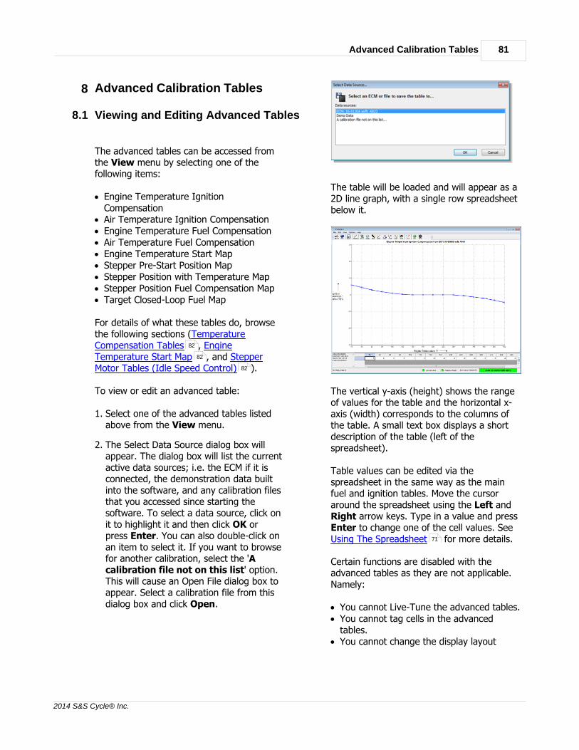
Advanced Calibration Tables 81
2014 S&S Cycle® Inc.
8 Advanced Calibration Tables
8.1 Viewing and Editing Advanced Tables
The advanced tables can be accessed fromthe View menu by selecting one of thefollowing items:
· Engine Temperature IgnitionCompensation
· Air Temperature Ignition Compensation· Engine Temperature Fuel Compensation· Air Temperature Fuel Compensation· Engine Temperature Start Map· Stepper Pre-Start Position Map· Stepper Position with Temperature Map· Stepper Position Fuel Compensation Map· Target Closed-Loop Fuel Map
For details of what these tables do, browsethe following sections (TemperatureCompensation Tables , EngineTemperature Start Map , and StepperMotor Tables (Idle Speed Control) ).
To view or edit an advanced table:
1. Select one of the advanced tables listedabove from the View menu.
2. The Select Data Source dialog box willappear. The dialog box will list the currentactive data sources; i.e. the ECM if it isconnected, the demonstration data builtinto the software, and any calibration filesthat you accessed since starting thesoftware. To select a data source, click onit to highlight it and then click OK orpress Enter. You can also double-click onan item to select it. If you want to browsefor another calibration, select the 'Acalibration file not on this list' option.This will cause an Open File dialog box toappear. Select a calibration file from thisdialog box and click Open.
The table will be loaded and will appear as a2D line graph, with a single row spreadsheetbelow it.
The vertical y-axis (height) shows the rangeof values for the table and the horizontal x-axis (width) corresponds to the columns ofthe table. A small text box displays a shortdescription of the table (left of thespreadsheet).
Table values can be edited via thespreadsheet in the same way as the mainfuel and ignition tables. Move the cursoraround the spreadsheet using the Left andRight arrow keys. Type in a value and pressEnter to change one of the cell values. SeeUsing The Spreadsheet for more details.
Certain functions are disabled with theadvanced tables as they are not applicable.Namely:
· You cannot Live-Tune the advanced tables.· You cannot tag cells in the advanced
tables.· You cannot change the display layout
82
82
82
71

S&S Cycle® ProTune 282
2014 S&S Cycle® Inc.
when viewing advanced tables.
When you have finished editing an advancedtable you can select Save Table… fromthe Options menu to save it to its originaldata source or Save Table To… to save itto a different data-source.
Certain advanced maps will have an enable/disable checkbox located under thespreadsheet. Checking this box will enablethe map in the ECM/Calibration file.Unchecking the box will ensure that the mapis not used in the ECM/Calibration file. Thearrow box located to the right of the check-box contains further information on thecheck-box setting.
When the check-box is unchecked, the mapvalues are 'grayed-out' and cannot be edited.The checkbox setting will be saved when themap is saved.
8.2 Temperature Compensation Tables
The temperature compensation maps adjustfuel and ignition as a function of the currentengine and air temperatures. For a fulldescription of how these compensationtables work, see The Fuel Injection System
and The Ignition Timing System .
8.3 Engine Temperature Start Map
The Engine Temperature Start Map adjuststhe fuel delivery during cranking as afunction of engine temperature. The tableadds a percentage of the input fuel injectorpulse width as a function of the enginetemperature.
For example if the compensation factor fromthe Engine Temperature Start Map is +85%and the input fuel injector pulse width is4ms, the output of the table will be 4 +(85% of 4) = 7.4ms.
See The Fuel Injection System for moredetails on how the fuel system works andhow fuel compensation works.
8.4 Stepper Motor Tables (Idle Speed Control)
The stepper-motor on your vehicle is used tocontrol the idle speed of the engine byautomatically adjusting the throttle valveposition by small amounts.
The stepper motor can drive the throttlevalve open by a small amount to allow moreair to pass and therefore increase enginespeed. It can also close the throttle by asmall amount to decrease engine speed.TheS&S Cycle® ECM has a closed-loopcontrol feature that allows automatic throttleopening and closing to maintain anappropriate and constant idle speed (thespeed of the engine when the throttle isclosed and the vehicle is not moving). It doesthis by trying to achieve the target idle speedtaken from the target idle speed table in theECM.
You can edit the target idle speed of the ECMby changing the Target Idle Speed Setting
. This is the speed that the ECM will try toattain when idling. When the engine isstarted, the target idle speed will be set atthe optimum value for the enginetemperature and conditions. As the enginewarms up and runs, the target idle speed willmove towards the value that you specify.
The initial stepper position when the enginestarts affects both the starting characteristicsof the engine and how quickly the required
60
60
65 66
65
44

Advanced Calibration Tables 83
2014 S&S Cycle® Inc.
idle speed can be attained after engine start.The stepper-motor position during crankingcan be tuned by adjusting the Stepper Pre-Start Position Map . This map can beenabled or disabled by using the checkboxpositioned below the map spreadsheet.When this checkbox is checked, the StepperPre-Start Position Map is enabled in the ECM/Calibration file and the values in this map willbe used to determine the stepper-motor pre-start position.
When the checkbox is unchecked, the Stepper Pre-Start Position Map is disabled inthe ECM/Calibration file and the stepper pre-start position will be set as a function of thelearned idle control value in the ECM.
The initial stepper position after engine startcan be adjusted as a function of initial enginetemperature by tuning the Stepper Positionwith Temperature Map . Both of thesetables have outputs ranging from 0 steps (noadditional throttle) to 205 steps (maximumadditional throttle).
The stepper motor should be wired so thatan increase in stepper number (0-205)corresponds to an increase in throttle. If youhave an application where the stepper-motorrequires different wiring, you can select theorientation mode of the stepper motor in theECM by editing the Stepper Motor OrientationSetting . This setting should be left asdefault unless you have specific reason tochange it.
As the stepper motor opens the throttle, youmay want to compensate for the extraengine speed by adjusting the fuel delivery.This can be done using the Stepper PositionFuel Compensation table. This table addsa percentage fuel compensation dependingon the degree of stepper motor travel. Themap can be enabled or disabled by using thecheckbox positioned below the mapspreadsheet. When this checkbox is checked,the Stepper Position Fuel Compensation table is enabled in the ECM/Calibration file andthe values in this map will be used to adjust
the fuel.
When the checkbox is unchecked, the Stepper Position Fuel Compensation table isdisabled in the ECM/Calibration file and thefuel will not be adjusted by this table.
9 Closed-Loop Fuel Control
9.1 The Closed-Loop Fuel Control System
The S&S® ECM supports the Closed-LoopFuel Control system. When fitted to a vehiclewith oxygen sensors in the exhaust system,this feature allows the ECM to learn (as theengine runs) the optimal fuel deliveryrequired to maintain a specific fuel mixture orAir-Fuel Ratio (AFR). The ECM can then usethat information to automatically adjust thefuelling towards that optimal value andcontinue refining the value to reach thedesired Air-Fuel Ratio.
Below is a diagram that summarizes how thissystem works. Each cylinder (Front and Rear)has its own separate Closed-Loop FuelControl system so the ECM can learn theoptimal fuel values for each cylinderindependently of the other.
The diagram shows that the ECM continuallycalculates how much fuel correction isneeded to adjust the current Air-Fuel Ratio tothe value required by the user. Optionally,
42
43
42
45

S&S Cycle® ProTune 284
2014 S&S Cycle® Inc.
that percentage correction may be stored inthe cylinder's Adaptive Map so that a patternof required fuel correction can be built upover different engine speeds and throttlepositions. The Closed-Loop Control Settings
allows the user to specify that thecurrent percentage correction is applied tothe current fuel output. In other words, theadjusted fuel output will affect the actualmeasured Air-Fuel Ratio, thus completing theloop.
ProTune 2 allows you to specify a generaltarget mixture for different engine speedsand throttle positions by editing the TargetClosed-Loop Fuel Map, see Setting the TargetAir-Fuel Mixture for details. It also allowsyou to decide whether the Adaptive Map is tobe changed and/or whether the currentAdaptive Map value is to be used to adjustthe current fuel output. This enables theoption of running the engine over time tobuild an Adaptive Map and then using it laterto correct the fuel. In addition, you cancontrol when and how the Adaptive Maps arereset.For details of these settings in Basic Mode,see Closed-Loop Setup in Basic Mode . Fordetails of these settings in Advanced Mode,see Closed-Loop Setup in Advanced Mode.
Once a successful Adaptive Map has beenbuilt up over time, you can use one of theProTune 2 merge functions to translate thepercentage corrections in the Adaptive Mapsto the cylinder fuel adjustment tables and/orthe main fuel table. See the section Using theAdaptive Maps for more details.
You can view the current state of the Frontand Rear cylinder Adaptive Maps, byselecting Front Cylinder Adaptive Map andRear Cylinder Adaptive Map from theView menu when a S&S® ECM is connected.The Adaptive Maps can be manually reset tozero percent correction at anytime byaccessing the Reset Adaptive Mapsfunction from the Options menu.
9.2 Closed-Loop Setup in Basic Mode
Select the Closed-Loop Control Settingsitem from the View menu in Basic Mode tospecify the Closed-Loop mode of operation inan ECM or Calibration file.
The Closed-Loop Control Settings dialog boxin Basic Mode has one settings drop-downlist:
Closed-Loop Fuel Control Mode. This setsthe mode of operation for the Closed-LoopControl System. The options are:
· No Closed-Loop or Adaptive. The ECMwill not place new values in the AdaptiveMaps or use the Adaptive Maps to adjustthe current fuel output. When editing thecurrent ECM or calibration file, the statusindicators on the main window will both beoff.
· Full Closed-Loop control. The ECM willupdate the Adaptive Maps with newpercentage correction values and use thevalues in the Adaptive Map to adjust thefuel output. When editing the current ECMor calibration file, the status indicators onthe main window will both be on.
37
86
84
85
87
45
46
64
37
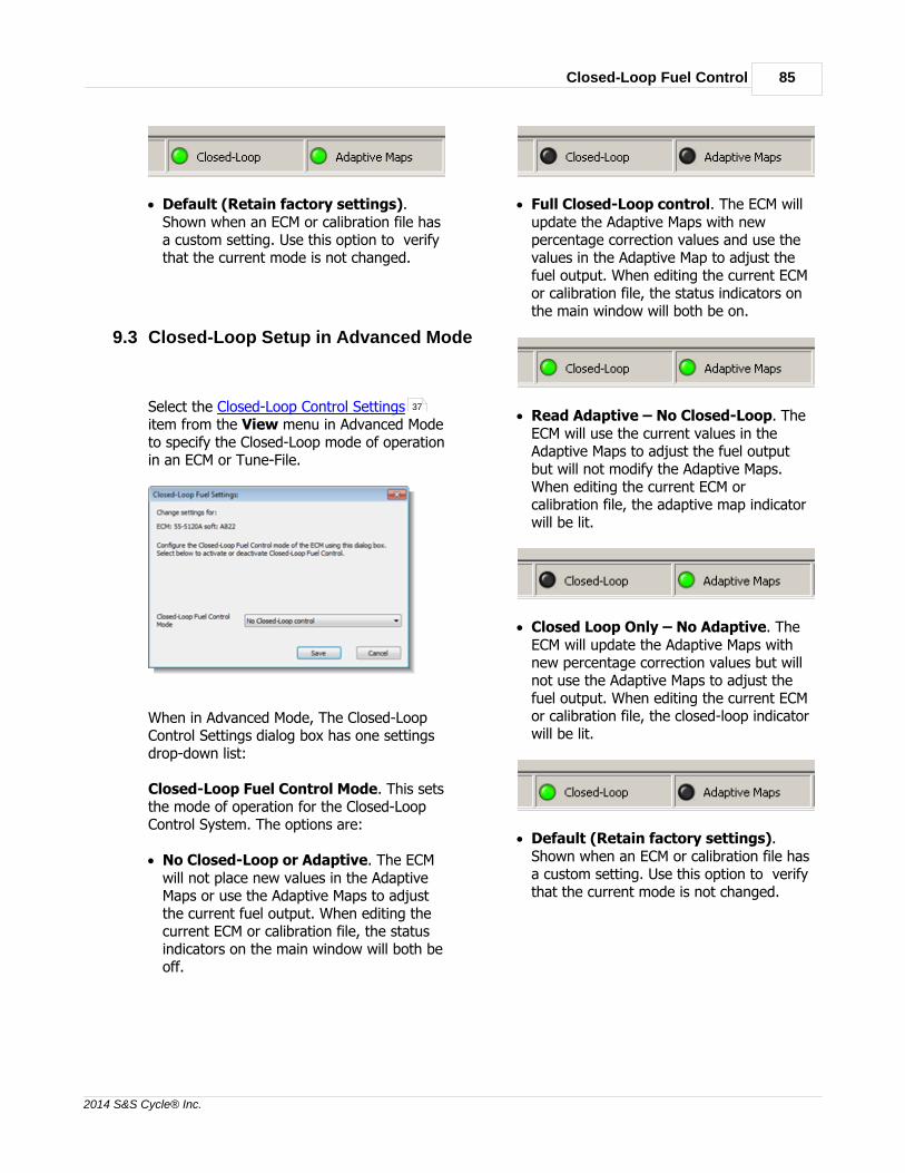
Closed-Loop Fuel Control 85
2014 S&S Cycle® Inc.
· Default (Retain factory settings).Shown when an ECM or calibration file hasa custom setting. Use this option to verifythat the current mode is not changed.
9.3 Closed-Loop Setup in Advanced Mode
Select the Closed-Loop Control Settingsitem from the View menu in Advanced Modeto specify the Closed-Loop mode of operationin an ECM or Tune-File.
When in Advanced Mode, The Closed-LoopControl Settings dialog box has one settingsdrop-down list:
Closed-Loop Fuel Control Mode. This setsthe mode of operation for the Closed-LoopControl System. The options are:
· No Closed-Loop or Adaptive. The ECMwill not place new values in the AdaptiveMaps or use the Adaptive Maps to adjustthe current fuel output. When editing thecurrent ECM or calibration file, the statusindicators on the main window will both beoff.
· Full Closed-Loop control. The ECM willupdate the Adaptive Maps with newpercentage correction values and use thevalues in the Adaptive Map to adjust thefuel output. When editing the current ECMor calibration file, the status indicators onthe main window will both be on.
· Read Adaptive – No Closed-Loop. TheECM will use the current values in theAdaptive Maps to adjust the fuel outputbut will not modify the Adaptive Maps.When editing the current ECM orcalibration file, the adaptive map indicatorwill be lit.
· Closed Loop Only – No Adaptive. TheECM will update the Adaptive Maps withnew percentage correction values but willnot use the Adaptive Maps to adjust thefuel output. When editing the current ECMor calibration file, the closed-loop indicatorwill be lit.
· Default (Retain factory settings).Shown when an ECM or calibration file hasa custom setting. Use this option to verifythat the current mode is not changed.
37

S&S Cycle® ProTune 286
2014 S&S Cycle® Inc.
9.4 Setting the Target Air-Fuel Mixture
You can specify the general target Air-FuelRatio for different engine speeds and throttlepositions by modifying the Target Closed-Loop Map. Select this map from the Viewmenu.
The map appears as a spreadsheet withsixteen Engine Speed columns and sixteenThrottle Position rows. Each cell of thespreadsheet specifies the required Air-Fuelmixture at that Engine Speed and ThrottlePosition. The spreadsheet is used in a similarway to other tables. Use the scroll bars atthe bottom and right corner of thespreadsheet to see all of the data. Thecursor, indicated by the black rectangle, maybe moved around the spreadsheet with the Left, Right, Up and Down arrow keys.Holding Shift while pressing the arrow keyswill enable you to select a rectangular areaof cells. The cursor position can also bechanged by clicking the mouse on therequired cell. Clicking and dragging across arange of cells will select an area of thespreadsheet. Clicking on column or rowheaders will select an entire column or row.Clicking and dragging across column or rowheaders will select multiple columns or rows.
A line indicates a division on the tablebetween Throttle Positions of 75% or moreopen and less than 75% open. You cannot
select the two leanest mixture options at75% throttle or above as a fuel rich mixtureis advised in this area. You cannot select therichest mixture option at less than 75%open.
To edit a cell value, or a selected area of cellvalues, click on the grey down-arrow boxwhich appears in the current cursor cell orpress the Enter key. This will display a drop-down list of options. An option can beselected using the cursor keys and pressing Enter or by clicking on the option with themouse. Press the Esc key if you want tocancel editing the current cell.
Each cell may be set to one of the followingmodes:
· RICHEST. Available only for throttlepositions equal to or greater than 75%open. Specifies a very highly fuel richmixture for this cell.
· RICHER. Specifies a highly fuel richmixture for this cell.
· RICH. Specifies a fuel rich mixture for thiscell.
· STOICH – Available only for throttlepositions less than 75% open. Specifiesthat the mixture should be stoichiometric,i.e. a balanced mixture of fuel and air forcomplete combustion.
· LEAN – Available only for throttle positionsless than 75% open. Specifies that themixture should be oxygen rich, i.e. lessfuel than required for completecombustion.
· NO CL – Specifies that no closed-loopcontrol should be performed at this EngineSpeed and Throttle Position. The AdaptiveMaps will not be updated at this location.
· DEFAULT – Used to indicate that the setupof this cell is custom and not one of thepresets. Leave as default if you want toleave the setup unchanged.
As a guide, the modes equate to thefollowing approximate Air-Fuel Ratios:

Closed-Loop Fuel Control 87
2014 S&S Cycle® Inc.
DescriptionApproximateAir-Fuel Ratio
Lean 14.8
Stoichiometric 14.65
Rich 14.2
Richer 13.6
Richest 13.2
9.5 Using the Adaptive Maps
Once Adaptive Maps are generated thatproduce the desired engine performance, thepercentage fuel correction stored in theAdaptive Maps can be applied to the cylinderfuel adjustment tables and/or main fuel mapin the ECM. The reason for doing this is toreduce the amount of adaptation required forfurther closed-loop running. The AdaptiveMaps are volatile. They may be modified bythe ECM with further closed-loop running andwill be lost if the permanent batteryconnection to the ECM is interrupted. Fordetails of these settings in Basic Mode, see Closed-Loop Setup in Basic Mode . Fordetails of these settings in Advanced Mode,see Closed-Loop Setup in Advanced Mode.
The values in the Adaptive Maps may beapplied to the ECM fuel tables by selectingeither Cylinder Trim Adaptive Map Mergeor Main Fuel Adaptive Map Merge fromthe Options menu. The Cylinder TrimAdaptive Map Merge function will modify theCylinder Fuel Adjustment tables (FrontCylinder Adjustment Table , Rear CylinderAdjustment Table ) with the Adaptive Mapvalues. The Main Fuel Adaptive Map Mergewill distribute the Adaptive Map correctionbetween the cylinder fuel adjustment tables
and the Fuel Injection Base Table . Whichoption you select depends upon whether youwant the base fuel table to be modified bythe process or left in its current state. Usingthe Main Fuel Adaptive Map Merge willreduce the magnitude of the change to thecylinder adjustment tables. Using thisfunction also averages the change across thetwo cylinders, which may be desirable forbalanced engine running. The Cylinder TrimAdaptive Map Merge function calculates eachcylinder separately.
The Cylinder Trim Adaptive Map Mergefunction operates as follows:
1. ProTune 2 loads the Front CylinderAdaptive Map, Rear Cylinder AdaptiveMap, Front Cylinder Fuel AdjustmentTable, Rear Cylinder Fuel AdjustmentTable from the ECM.
2. It adjusts the current value in the CylinderAdjustment Table by an amountproportional to the Adaptive Mappercentage correction, for each cylinder.
3. ProTune 2 then sends the modified theCylinder Adjustment Tables back to theECM.
4. The Adaptive Maps are reset to zero.
The Main Fuel Adaptive Map Mergefunction operates as follows:
1. ProTune 2 loads the Front CylinderAdaptive Map, Rear Cylinder AdaptiveMap, Front Cylinder Fuel AdjustmentTable, Rear Cylinder Fuel AdjustmentTable and the Fuel Injection Base Tablefrom the ECM.
2. Works out the total adjustment for eachcylinder by adding the current value in theFuel Adjustment Table to the percentagecorrection in the Adaptive Map.
3. Averages the two total adjustment valuesfor the two cylinders.
4. Compensates the values in the FuelInjection Base Table by this averageadjustment (for example, if the averagetotal adjustment is +100%, this will resultin a doubling of fuel at that location in the
84
85
63
63
35
36
35

S&S Cycle® ProTune 288
2014 S&S Cycle® Inc.
fuel table).5. Calculates the difference between the
average total adjustment and the totaladjustment for each cylinder. Stores thisdifference in the Cylinder Fuel Adjustmenttables.
6. ProTune 2 then sends all modified tablesback to the ECM.
7. The Adaptive Maps are reset to zero.
You can view the current state of the Frontand Rear cylinder Adaptive Maps, byselecting Front Cylinder Adaptive Map andRear Cylinder Adaptive Map from theView menu when a S&S® ECM is connected.The Adaptive Maps can be manually reset tozero percent correction at anytime byaccessing the Reset Adaptive Mapsfunction from the Options menu.
10 Knock (Adaptive Ignition) Control
10.1 The Knock Control System
The 55-5069 USB ECM supports a KnockControl system. When fitted to a vehicle witha knock sensor, this feature allows the ECMto adjust the ignition timing to avoid engineknocking (also called pinging or detonation).
The Knock control system can operate in oneof three modes. You can select the mode foryour ECM by selecting Knock Control Settings
from the View menu.
· Learned and instantaneousadjustment. The ECM will adjust ignitiontiming to avoid engine knocking.Adjustments are made as knocking occursand long-term adjustments are stored.
· Instantaneous adjustment only (non-learned). The ECM will adjust ignitiontiming to avoid engine knocking as itoccurs. Long term adjustments are notstored.
· Disabled. Knock Control is not enabledand no adjustments to ignition timing aremade due to engine knocking.
You can view the long term adjustmentsmade due to engine knocking by selectingthe Adaptive Ignition Map from the Viewmenu. The Adaptive Ignition Map can bereset by selecting Reset Adaptive Mapsfrom the Options menu.
11 Diagnostics
11.1 Frequently Asked Questions
The 3D graph does not appear orappears as an empty rectangle on myPC.
45
46
64
38
47
64

Diagnostics 89
2014 S&S Cycle® Inc.
This may be cause by the color resolution ofyour PC being set too low for ProTune 2 (forexample, if Windows® is set to 256 or 16color mode). ProTune 2 requires a colorresolution of 16-bit color (thousands ofcolors) or greater. To change your colorresolution, go to the Start menu and launchControl Panel (this may be in the Settings menu). Double-click on the Display icon.Click on the Settings tab. The color settingscan be adjusted by selecting an item fromthe Color Quality drop-down list. Select eitherthe 16-bit, 24-bit or 32-bit color options.Some Windows versions may require thatyou restart your computer for the new colorsettings to take effect. If you do not have 16-bit, 24-bit or 32-bit color options it is likelythat you will need to update your graphicssystem to run ProTune 2 successfully.
The 3D graph is drawn very slowly ordoes not update correctly on my PC.
You may need to update the graphics driveron your PC. A graphics driver is an item ofsoftware that allows Windows to sendinstructions to your video display system. Goto the website of your video systemmanufacturer and search for the latest driverfor your version of Windows. Themanufacturer and model of your videodisplay system can be found by accessingthe Start menu and launching ControlPanel (this may be in the Settings menu).Double-click on the Display icon. Click onthe Settings tab. Click on the Advancedbutton. Click on the Adapter tab. Theproperties of your video display system willbe shown in the dialog box.
ProTune 2 does not communicate withmy serial ECM.
1. Check that the ECM is powered. The ECMmust be supplied with vehicle power inorder to operate. Your vehicle ignition keyand kill switch should be set to the ON andRUN positions. Make sure that the batterylevel is normal. Try cycling the power tothe ECM (switch off ignition for 15 seconds
and then switch on).
2. Check that the cable is connected firmly tothe ECM and the PC.
3. Some PCs may have more than one serialport. If this is the case, try connecting tothe other port(s).
4. The external serial port on your PC mightnot be installed as COM1. This is the caseon some models of notebook computersthat use COM1 for other devices (modems,IR ports, etc). You will need to change theserial port that ProTune 2 checks for ECMson. Try searching on COM2 instead ofCOM1. See Serial Port Settings… fordetails on how to detect the port setup ofyour computer. For detailed information onthe port setup of your PC, go to theWindows Start menu, open the ControlPanel (this may be in the Settingsmenu). Open the System control panel.Click on the Hardware tab. Click DeviceManager. Under the group labeled Portsthe available serial ports should be listed.The serial port names will start with theletters 'COM'.
ProTune 2 does not communicate withmy USB ECM.
1. Check that the ECM is powered. The ECMmust be supplied with vehicle power inorder to operate. Your vehicle ignition keyand kill switch should be set to the ONand RUN positions. Make sure that thebattery level is normal. Try cycling thepower to the ECM (switch off ignition for15 seconds and then switch on).
2. Check that the cable is connected firmly tothe ECM and the PC.
3. Try disconnecting and reconnecting theUSB connection to the ECM. This will resetthe ECM connection and allow Windows torelocate the device.
55

S&S Cycle® ProTune 290
2014 S&S Cycle® Inc.
4. Have you installed the USB drivercorrectly? The first time you connect theECM to a PC, you will need to install thesupplied device driver. Please refer to the USB Device Driver Installation sectionfor more details on this.
5. See Troubleshooting USB Driver Problems for more help.
Windows reports 'locked files' when Iam upgrading or removing ProTune 2.Make sure all applications (especiallyProTune 2 itself) are closed before youattempt to upgrade or remove ProTune 2from your PC. To be sure that all applicationsare closed, you may wish to restart yourcomputer and retry the upgrade/removalprocess.
11.2 Troubleshooting USB Driver Problems
If an error occurs during the installation ofthe USB device driver, or the device does notcommunicate with ProTune 2, it may benecessary to manually check the connectionto the ECM in Windows® and reinstall theUSB driver. To install the USB driver for thefirst time see USB Device Driver Installation
.
To check the device connection and reinstallthe driver, follow these steps:
1. Close all programs, including ProTune 2.
2. Check that the ECM is powered. The ECMmust be supplied with vehicle power inorder to operate. Your vehicle ignition keyand kill switch should be set to the ONand RUN positions. Make sure that thebattery level is normal.
3. Check that the cable is connected firmly tothe ECM and the PC.
Now follow the instructions belowappropriate to your version of Windows.
Windows® XP
Windows® Vista™ & Windows® 7
11.2.1 Windows® XP
1. Go to the Start menu button.
2. Select Control Panel from the menu.
3. Double-click the System icon.
4. Select the Hardware tab.
5. Click the Device Manager button tolaunch the Device Manager window.
6. There should be a group of devicesnamed Automotive Controllers andInterfaces. This group should containone Vehicle Control System orInterface Unit item. If not, the devicehas not been installed correctly. Searchunder the Other devices and UniversalSerial Bus controllers groups for anyECM devices that have a yellowexclamation mark symbol next to them. Ifyou cannot find any related items then theUSB ECM has not been detected by thePC. Check that the ECM is installedcorrectly, powered and the cable issecurely connected and not damaged.Contact customer support if this does notsolve the problem.
7. If you find the device listed with a yellowexclamation mark symbol next to it, rightclick the item and select Uninstall. Thedevice icon should disappear. Now unplugthe USB cable from the PC and reattach it.If the Found New Hardware dialog box
9
90
9
90
91

Diagnostics 91
2014 S&S Cycle® Inc.
appears, follow the steps described in the USB Device Driver Installation section.
8. If the device continues to be listed with ayellow exclamation mark, right click theitem and select Properties. Make a noteof the Device status message. Click theDriver tab. Click Update Driver... andfollow the steps described in the USBDevice Driver Installation section, ormanually select the driver in the ProTune2 directory (C:\Program Files\S&SCycle\ProTune 2). Contact customersupport if this does not solve the problem.
11.2.2 Windows® Vista™, 7 and 8
1. For Windows® Vista™ and Windows® 7,go to the Windows® icon button on thetask-bar. For Windows® 8, in desktopmode, mouse down to the bottom-rightcorner of the screen and click on Settings.
2. Select Control Panel from the menu.
3. Click the System and Maintenance orSystem and Security link.
4. Click the System link.
5. Click the Device Manager link in theTasks pane.
6. Depending on your security settings, amessage may appear asking forpermission to continue. Click Continue.
7. There should be a group of devicesnamed Automotive Controllers andInterfaces. This group should containone Vehicle Control System orInterface item. If not, the device has notbeen installed correctly. Search under the Other devices and Universal SerialBus controllers groups for any ECMdevices that have a yellow exclamation
mark symbol next to them. If you cannotfind any related items then the USB ECMhas not been detected by the PC. Checkthat the ECM is installed correctly,powered and the cable is securelyconnected and not damaged.
8. If you find the device listed with a yellowexclamation mark symbol next to it, rightclick the item and select Uninstall. Thedevice icon should disappear. Now unplugthe USB cable from the PC and reattach it.If the Found New Hardware dialog boxappears, follow the steps described in the USB Device Driver Installation section.
9. If the device continues to be listed with ayellow exclamation mark, right click theitem and select Properties. Make a noteof the Device status message. Click theDriver tab. Click Update Driver... andfollow the steps described in the USBDevice Driver Installation section, ormanually select the driver in the ProTune2 directory (C:\Program Files\S&SCycle\ProTune 2\drivers). Contactcustomer support if this does not solve theproblem.
11.3 Check Engine Lamp Diagnostics
The S&S Cycle® ECM has a feature whichcan report engine faults by flashing a codevia the Check Engine lamp on the vehicle.
Note: if you have set your vehicle to use thecheck engine lamp as a shift-light, thisfunction will be disabled.
The procedures to activate and read thecheck engine lamp are as follows:
1. Turn the ignition switch to the on positionfor three seconds (one second pause afterthe fuel pump stops), and then switchback to the off position for three seconds.
9
9
9
9

S&S Cycle® ProTune 292
2014 S&S Cycle® Inc.
Repeat this procedure one more time andthen turn the ignition to the on positionand wait for eight seconds for the checkengine lamp to start flashing.
2. The transmission of a code is alwayspreceded by a series of rapid flashes(about 3 per second). This "intermission"is followed by a 2 second pause in whichthe lamp is off. The lamp will then flashone or more times to indicate the first digitof the trouble code. The length of time thelamp is illuminated and the length of timein which it is off are each about 1 secondin duration. The number of times the lampflashes indicates the first digit of thetrouble code.
3. Following the transmission of the firstdigit, there is another 2-second pause inwhich the lamp is off. The lamp will thenflash one or more times to indicate thesecond digit of the trouble code. Thenumber of times the lamp flashes indicatesthe second digit of the trouble code.
4. Following the transmission of the seconddigit, there is a third 2-second pause inwhich the lamp is off. After the pausecomes an "intermission", followed bytransmission of the next recorded troublecode. All subsequent codes are sent in thesame manner, each separated from thenext by an "intermission". Once thetrouble codes have been sent the datastring is repeated. See the Check EngineLamp - Fault Flashing Codes for a listof the trouble codes supported.
5. Turn the Ignition Key switch to off. Wait10 seconds for the ECM relay to click.Vehicle can now be started normally.
11.4 Speedometer Diagnostics
The S&S Cycle® 55-5069 USB ECM has a
feature which can report engine faultsthrough the vehicle odometer of the stockspeedometer on a 2004 or newer vehicle. Acomputer cable is not required for thesediagnostics.
The procedures to activate and read thespeedometer diagnostic trouble codes are asfollows:
1. With the Ignition switch Off and the Run/Stop switch set to Run, press and hold theodometer reset button. The odometer willlight up and display the total mileage.
2. While pressing the odometer reset button,turn the Ignition switch to the Ignposition. Then release the odometer resetbutton. The speedometer andtachometer, if equipped, will do full rangesweeps and light all the indicator lights.The odometer will display "diAG".
3. Press and release the odometer resetbutton again. The odometer will display“PSSPt”, with the first P blinking. Theblinking letter indicates which module isselected to send diagnostic information.The first “P” is the Electronic ControlModule (ECM). The first “S” is the TurnSignal Module (TSM). The “SP” is theSpeedometer. The “t” is the Tachometer.
4. Press and release the odometer resetbutton to select the desired module fromthe list above. As you cycle through the P,S, SP, and t, the selected digits will blink.
5. To view the diagnostic fault codes in theselected module, press and hold theodometer reset button for about 4seconds. The odometer will display a 5digit code for any fault codes that arepresent. Record the fault codes. If thereare not any trouble codes set on theselected module, the odometer will display“nonE”.
6. Press and release the odometer resetbutton to toggle through the remaining
93

Diagnostics 93
2014 S&S Cycle® Inc.
fault codes, if any are present. Theodometer will display “End” when all thefault codes present have been displayed. See the Check Engine Lamp - FaultFlashing Codes for a list of the troublecodes supported.
7. To clear the diagnostic fault codes on theselected module, press and hold the resetbutton for about 4 seconds. Theodometer will display “CLEAr” afterclearing the trouble codes.
8. If you do not want to clear the troublecodes, press and release the reset button. The part number of the selected modulewill scroll across the odometer.
9. Press and release the reset button again. The odometer will now be back to step 3. You may now retrieve diagnostic troublecodes from a different module. Turningthe Ignition switch to Off at any point willexit the speedometer diagnosticsprocedure.
11.5 Check Engine Lamp - Fault Codes
The fault-flashing codes correspond to thefollowing fault conditions:
Check EngineLamp Flash
Code
SpeedometerDiagnostic
Code
FaultCondition
11 P0122 ThrottlePositionSensor
Low/ShortCircuit
11 P0123 ThrottlePositionSensor
High/OpenCircuit
12 P0105 BarometricPressureSensor
Malfunction
12 P0108 MAP/BaroSensor
Low/OpenCircuit
14 P0117 EngineTemperature
SensorLow/Short
Circuit
14 P0118 EngineTemperature
SensorHigh/Open
Circuit
15 P0113 Intake AirTemperatureHigh/Open
Circuit
15 P0112 Intake AirTemperatureLow/Short
Circuit
16 P0562 SystemVoltage
(Battery) Low
16 P0563 SystemVoltage
(Battery)High
23 P0261 Front InjectorOpen Circuit
23 P0262 Front InjectorShort Circuit
32 P0264 Rear InjectorOpen/Low
32 P0265 Rear InjectorShort/High
34 P0505 StepperMotor
93

S&S Cycle® ProTune 294
2014 S&S Cycle® Inc.
Malfunction
52 P0604 ECM RAMError
53 P0605 ECM FlashError
54 P0603 ECM EEPROMError
55 P0606 Microprocessor
Malfunction(ECM
Processor)
P0217 OverheatProtectionStage 1
P0217 OverheatProtectionStage 2
P0217 OverheatProtectionStage 3
71 P0327 Knock SensorCircuit Low
Input
72 P0328 Knock SensorCircuit High
Input
P0132 Front O2Sensor High
Voltage
P0134 Front O2Sensor
Open/NotResponding
P0170 FrontAdaptive
Maxed Out
P0152 Rear O2Sensor High
Voltage
P0154 Rear O2Sensor
Open/NotResponding
P0173 Rear Adaptive
Maxed Out
12 Glossary
BOX (file)A complete copy of the state of an ECM,including ECM software and all data. This is afile containing new ECM software and/or datawhich can be used to update and backup thestate of ECMs. A BOX file is a type ofcalibration file, the other being a Tune-File.
Calibration (File)A file that stores a copy of ECM data and/orsoftware. Specifically, a calibration file iseither a BOX file type or a Tune-File type.
CellA single site or value in a table.
ChannelA real-time measurement from the ECM.Either an input value, output value, or ECMcalculation.
Closed-Loop (Fuel Control)A method of continuously adapting theengine fuel delivery to obtain an idealmixture (ratio of fuel to air) for specificengine performance.
Data SourceA source of calibration data, either an ECM,BOX file, or a Tune-File.
DTCDiagnostic Trouble Code. A record of a faultor error condition stored in the ECM memory.
ECC (file)See Tune-File below.
ECMElectronic Control Module. An electronicdevice which controls a vehicles engine andother systems. Also known as a VFI (Variable

Glossary 95
2014 S&S Cycle® Inc.
Fuel Injection) module.
ECM Upgrade FileSee BOX file above.
GaugeA display of real-time information from theECM.
H86 (file)An ECM software program file. If an updateof the ECM program is required, S&S Cycle®can supply a new program in the form of anH86 file.
Idle-ControlA method of continuously adjusting the airflow into the engine in order to obtain asmooth engine idle condition.
Live-Tune (Live-Tuning)A method of tuning where changes made bythe user immediately effect the performanceof the ECM.
MapSee Table below.
Setting (ECM)A value in the configuration data of the ECMwhich globally controls an ECM feature(example - engine rev limiter value).
SiteSee Cell above. Also used as a unit todenote a value with a fixed interval, oftenused as an index into a table. For example,throttle position site is used as an index intotables that reference throttle position.
TableA grid of numbers inside the ECM used tocontrol engine actuators such as fuelinjectors and ignition coils. The output of atable will typically vary as a function ofcurrent engine speed and current throttleposition.
Tune-FileA Tune-File is a copy of the configurationdata, tables, and settings in an ECM which isstored as a file on disk. Tune-Files are usedto backup, restore and exchange ECMconfigurations. A Tune-File is a type ofcalibration file, the other being a BOX file.
TuningThe process of determining table values toproduce the best performance for aparticular application.
13 Footnote
All brand names, trademarks or registeredtrademarks mentioned in this document arethe property of their respective holders andare used in a reference capacity only.


Index 97
2014 S&S Cycle® Inc.
Index- 3 -3D Graph Settings 30
- A -About ProTune II 65
Acceleration Fuel Settings 36
Activating Live-Tune Mode 76
Advanced User Level 15, 19
Air Temperature Fuel Compensation 40
Air Temperature Ignition Compensation 39
Always On Top setting 80
Average Selected Area 26
- B -Basic User Level 15, 17
- C -Changing the Grid Size of the Spreadsheet 74
Changing the Spreadsheet and Graph Layout 75
Check Engine Lamp Diagnostics 91
Clear All Markers 27
Clear Historic Diagnostic Trouble Codes 64
Closed-Loop Control Settings 37
Closed-Loop Setup 84, 85
Comment Field 48
Connecting the ECM 15, 16
Copy 25
Copy Calibration File 61
Current Data Source menu 47
Cycle Graph-Line Resolution 28
Cycle Grid Size 28
Cycle Grid/Graph Position 27
Cylinder Trim Adaptive Map Merge 63
- D -Deactivating Live-Tune Mode 77
Device Driver 9, 90
Diagnostic Trouble Codes 33
Diagnostics 92
Download Code to ECM 56
Download Tune-File TO ECM 22, 57
- E -ECM 83
ECM Basic Setup 31
ECM Gauges 34
Editing Table Values 72
Engine Temperature Fuel Compensation 40
Engine Temperature Ignition Compensation 38
Exit 24
- F -Frequently Asked Questions 88
Fuel Injection Base Table 35
- G -Getting Started 12
- H -Help 14
Help Topics 65
- I -Ignition Timing Base Table 35
Installation 7, 9
Interpolate Selected Area 26
- L -Left Cylinder Adaptive Map 45
Left Cylinder Adjustment Table 35
Live-Tune 29
Live-Tune Mode 75
Live-Tune Mode On/Off 29

S&S Cycle® ProTune 298
2014 S&S Cycle® Inc.
- M -Main Fuel Adaptive Map Merge 63
Main Window 17, 19
Menu Bar 21
Menus - View Menu - Engine Temperature Start Map 82
- O -Open Table from 59
- P -Paste 25
Preferences 54
- R -Removal 12
Reset Adaptive Maps 64
Right Cylinder Adaptive Map 46
Right Cylinder Adjustment Table 36
- S -Save Table 60
Save Table To 60
Saving the Gauges Window Layout 80
Select User Level 54
Selecting an Area of the Table 72
Serial Port Settings 55
Serial Settings 15
Setting and Moving the Cursor Position 71
Setting the Target Air-Fuel Mixture 86
Speedometer Diagnostics 92
Stepper Motor Orientation Setting 42
Stepper Motor Tables (Idle Speed Control) 82
Stepper Position Fuel Compensation 45
Stepper Position with Temperature Map 43
Stepper Pre-Start Position Map 42
Switch On/Off Auto-Tagging in LiveTune 29
Switch On/Off Map Cursor Pop-up 28, 30
System Requirements 7
- T -Tag / Untag Cells 26
Tag/Untag Cells 73
Target Closed-Loop Fuel Map 46
Target Idle Speed Setting 44
Temperature Compensation Tables 82
Test Outputs 61
The Closed-Loop Fuel Control System 83
The Engine Data Area 80
The Fuel Injection System 65
The Ignition Timing System 66
To Add a Dial or Text Gauge 79
To Remove a Gauge 79
Tool Bar 21
Trouble Codes 93
Tune-File 22, 24, 57, 58, 61
Tuning in Live-Tune Mode 76
- U -Undo 25
Upload Tune-File FROM ECM 24, 58
USB 9, 90
USB Settings 16
User Levels 15
Using Math Functions to Adjust Table Values 73
Using the 3D Graph 74
Using the Adaptive Maps 87
Using the Gauges Window 78
Using The Spreadsheet 71
- V -Viewing and Editing Advanced Tables 81