SAMPE BENELUX STUDENT SEMINAR - Vlaams Instituut voor de … · infusion set-up in the workshop. At...
42
SAMPE BENELUX STUDENT SEMINAR Book of Abstracts January 2010 UT-CTW-TM-10/5626
Transcript of SAMPE BENELUX STUDENT SEMINAR - Vlaams Instituut voor de … · infusion set-up in the workshop. At...
SAMPE BENELUX
STUDENT SEMINAR
Book of Abstracts
January 2010
UT-CTW-TM-10/5626

Contents
Program . . . . . . . . . . . . . . . . . . . . . . . . . . . . . . . . . . 5Sponsors . . . . . . . . . . . . . . . . . . . . . . . . . . . . . . . . . . 7Lina Osorio – Microstructural And Mechanical Characterisation Of
Bamboo (Guadua Angustifolia) Fibres . . . . . . . . . . . . . . 17Diederik van Nuffel – An Experimental Study On Repetitive Slam-
ming Wave Impact On Deformable Composite Structures . . . 19Bianca Nellen – Manufacture Of Composite Sub-Structure Repairs
For Aircraft Structures . . . . . . . . . . . . . . . . . . . . . . . 21Bo Cornelissen – Tow Mechanics: Improving The Accuracy Of
Deformation Modelling . . . . . . . . . . . . . . . . . . . . . . . 23Eduardo Trujillo – Bamboo Fibre Thermoplastic Composites For
Structural Applications . . . . . . . . . . . . . . . . . . . . . . . 25Steven Bakker – Using Microtomography And Numerical Predictions
For The Investigation Of Failed Composites . . . . . . . . . . . 27Jeroen van de Zand – Automated Double Cantilever Beam test system
– A two-axis moving camera setup controlled by image analysisfor crack recognition . . . . . . . . . . . . . . . . . . . . . . . . 29
Kameswara Sridhar Vepa – Numerical Investigation And ComparisonOf Slamming Loads On Rigid And Deformable CylindricalStructures . . . . . . . . . . . . . . . . . . . . . . . . . . . . . . 31
Gustavo Guerriero – Self-Reinforcing High performance PolymerCoatings For Aerospace Applications . . . . . . . . . . . . . . . 33
Toon van Vugt – Energy Release Rate Concept Validation OnDelamination Behaviour Of A CFRP Wet Lay-Up Scarf JointRepair . . . . . . . . . . . . . . . . . . . . . . . . . . . . . . . . 35
Route Ermelo – Nijverdal . . . . . . . . . . . . . . . . . . . . . . . . 37Winners . . . . . . . . . . . . . . . . . . . . . . . . . . . . . . . . . . 41
3

4 SAMPE Benelux

Book of Abstracts 5
Program
Tuesday, January 12th
v.a. 12:00 Arrival & Registrationv.a. 12:15 Lunch12:45 Opening/Introduction Sampe Benelux13:00 Introduction Sponsors13:30 Keynote by A. Offringa - Fokker Aerostructures
First Student Session14:00 Lina Osorio14:25 Diederik van Nuffel14:50 Bianca Nellen
15:15 Coffee & Tea Break
Second Student Session15:30 Bo Cornelissen15:55 Eduardo Trujillo16:20 Steven Bakker16:45 Jeroen van de Zand
17:10 Coffee & Tea Break
Third Student Session17:25 Kameswara Sridhar Vepa17:50 Gustavo Guerriero18:15 Toon van Vugt
18:40 Closure of sessions & jury consult19:30 Dinner21:00 Announcement of winners & Evening drink
Wednesday, January 13th
8:00 Breakfast9:00 Departure to Ten Cate Advanced Composites, Nijverdal (NL)10:30 Visit to Ten Cate Advanced Composites, Nijverdal (NL)13:00 Lunch & Closure

6 SAMPE Benelux

Book of Abstracts 7
Sponsors of the 8th SAMPE Benelux Student Event
The student event is sponsored by a number of companies:
• Kok & Van Engelen http://www.kve.nl
• Airborne www.airbornecomposites.com
• Composite Technology Centre (CTC) http://www.ctcgroup.nl
The SAMPE Benelux Board thanks the support of these companies. It wouldnot have been possible to organise this event without their support.
The organisation also acknowledges Ten Cate Advanced Composites forarranging a visit to their facilities in Nijverdal (http://www.tencate.com/) andkeynote speaker Arnt Offringa from Fokker Aerostructures (http://www.fokker.com/aesp).

8 SAMPE Benelux
KVE Composites Group
Composite Structures
Design, development and manufacturing of composite structures and components is the main
pursuit of KVE Composites Group.
Innovation and performance
Our customers are looking for product innovations and enhanced product performance, and in many
cases the use of fiber reinforced components makes this possible. Generally, composites are
applied where structural, thermal, weight, resonance behavior and durability problems are
encountered. The flexible and innovative mindset of KVE ensures that solutions are found for virtually
every design and manufacturing challenge.
Markets
Traditionally, KVE has served the markets where composite structures are extensively used. These
markets are the aerospace industry, medical technology and defense systems. Nowadays, also other
industries like automotive, machine construction and civil engineering are finding their way to KVE
Composites Group.
Design and Development
Extensive knowledge and experience is employed in the design and development of structures,
technical products and systems using composites. All steps in the product realization process, ranging
from conceptual design to series manufacturing, are executed by KVE Composites Group,
whether as advisor or as turnkey project manager.
Manufacturing
Manufacturing of composites structures and components is offered from our well equipped facilities
in The Hague Ypenburg. KVE Composites Group uses the best suited manufacturing process,
ranging from vacuum infusion, resin transfer moulding, compression moulding to
prepregging/autoclaving.
MRO
Employing material knowledge and process experience of composites, KVE Composite Group offers
repair services for composites and metal bonded aircraft components from our EASA Part 145
approved composites repair facilities in Maastricht Aachen Airport.
KVE Induct
Developed at the KVE labs, the induction welding technology for carbon fiber reinforced
thermoplastics is now being used for the manufacturing of aircraft components. It is an example of a
very successful innovation in aerospace assembly technology.
Research
Research and Technology Development supports our engineering and manufacturing services,
keeping KVE Composites Group at the forefront of the composites industry. We also have access
to a large, international network of information from specialized companies, research organizations
and universities, enabling us to integrate the right technology for the right problem.
Employment
KVE Composites Group is continuously looking forward to meet motivated people to further
strengthen our team. Please contact us when you are interested to work in a high tech environment.

10 SAMPE Benelux
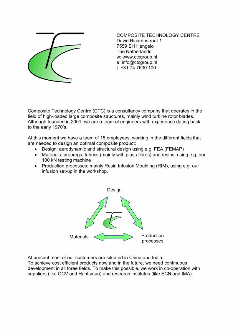
Design
Materials Production processes
COMPOSITE TECHNOLOGY CENTRE David Ricardostraat 1 7559 SH Hengelo The Netherlands w: www.ctcgroup.nl e: [email protected] t: +31 74 7600 100 Composite Technology Centre (CTC) is a consultancy company that operates in the field of high-loaded large composite structures, mainly wind turbine rotor blades. Although founded in 2001, we are a team of engineers with experience dating back to the early 1970’s. At this moment we have a team of 15 employees, working in the different fields that are needed to design an optimal composite product:
• Design: aerodynamic and structural design using e.g. FEA (FEMAP)
• Materials: prepregs, fabrics (mainly with glass fibres) and resins, using e.g. our 100 kN testing machine
• Production processes: mainly Resin Infusion Moulding (RIM), using e.g. our infusion set-up in the workshop.
At present most of our customers are situated in China and India. To achieve cost efficient products now and in the future, we need continuous development in all three fields. To make this possible, we work in co-operation with suppliers (like OCV and Huntsman) and research institutes (like ECN and IMA).

12 SAMPE Benelux
Met beide benen op de
gronden het hoofd in de wolken
Techniek is voor nuchtere mensen, voor vakmensen die met beide benen stevig op de grond staan. Bij Fokker Aerospace Group en de bedrijfsonderdelen Fokker Aerostructures, Stork SP Aerospace, Fokker Services, Fokker Aircraft Services en Fokker Elmo is dat niet anders. Maar nuchterheid gaat daar samen met begeestering. Ruim 3.700 medewerkers ervaren dag in dag uit hoe inspirerend het is om voor de lucht- en ruimtevaartindustrie en de bekendste luchtvaartmaatschappijen ter wereld technische hoogstandjes te verrichten. Die medewerkers zijn op zoek naar collega’s die het hoofd koel houden, maar wel graag warm lopen voor een loopbaan in de luchtvaartindustrie.
www.fokker.com
Met beide benen op de
grondbenen op de
grondbenen op de
10001 SPR ADV Stork Met beide benen op de grond 195x235.indd 1 05-01-10 10:25

14 SAMPE Benelux

AIRBORNE Airborne International Airborne develops and produces advanced composite products, for a variety of markets. It turns innovative know-how into industrialised production, through integrated Design and Build programmes. Airborne operates state-of-the-art engineering and production facilities, and is dedicated to quality, customer satisfaction and cost-efficiency. In the rapidly evolving world of composites, Airborne is committed to develop new game-changing technologies, in materials, processes and product design. Airborne consists of the following business units: Airborne Composites Netherlands Design and Build of advanced composites Airborne Composites Spain Design and Build of advanced composites Airborne Composite Tubulars Thermoplastic composite tubulars for the oil & gas industry Airborne Technology Centre The Airborne Technology Centre is founded to develop the new, differentiating composite technologies for future new business for Airborne. It reflects the ambition of Airborne to be a Technology Leader in composites. The following five Research themes are defined: Thermoplastic composites Thermoplastic tape placement, in-situ consolidation, autoclave/oven consolidation, welding Injection and preform technologies RTM and VARTM, automated preforming techniques, fast curing maerials Smart structures Integration of sensors and/or active materials, nano-composites, self-healing Simulation Composite mechanical behaviour, simulation of process-induced effects Automation Automated Fibre Placement, fiber steering, Continuous Winding process, machining of composites

16 SAMPE Benelux
Book of Abstracts 17
Microstructural And Mechanical Characterisation Of Bamboo(Guadua Angustifolia) Fibres
L. Osorio, E.Trujillo, A.W. Van Vuure, I. VerpoestKatholieke Universiteit Leuven, Department of Metallurgy and MaterialsEngineering, Kasteelpark Arenberg 44 bus 2450, 3001 Heverlee, Belgium
Keywords: Bamboo fibres, Fibre microstructure, Mechanical properties
Thanks to their good mechanical properties and low density, bamboo fibresrepresent one of the best alternatives among the natural fibres. In other words,specific mechanical properties of bamboo fibres are comparable to those of glassfibres.Guadua angustifolia is the most important bamboo specie of South Americaand one of the giant bamboos in the world. Their potential and possibilitiesare being studied in the frame of the project “Development of Bamboo fibrecomposites”.
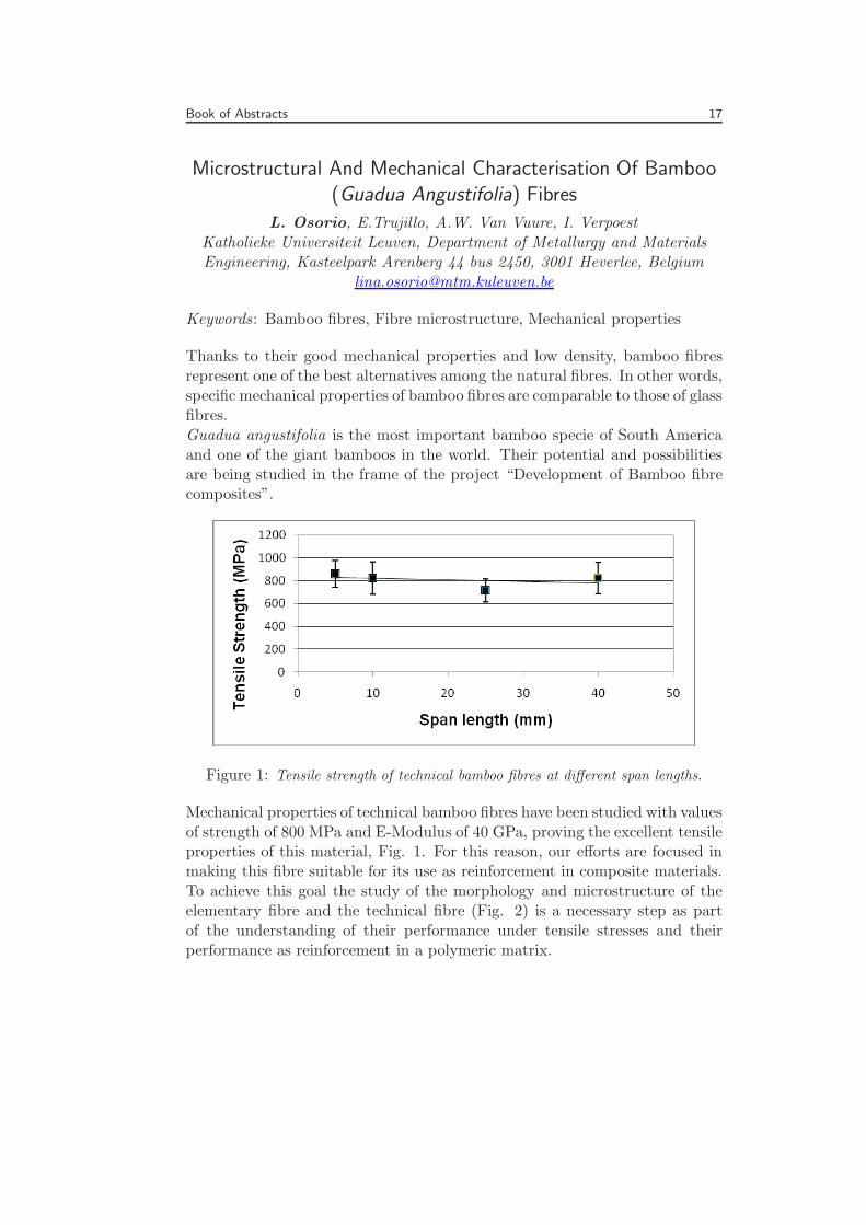
Figure 1: Tensile strength of technical bamboo fibres at different span lengths.
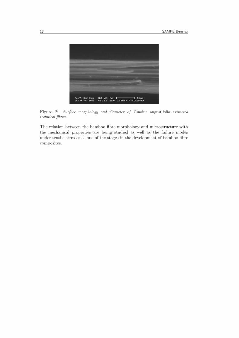
Mechanical properties of technical bamboo fibres have been studied with valuesof strength of 800 MPa and E-Modulus of 40 GPa, proving the excellent tensileproperties of this material, Fig. 1. For this reason, our efforts are focused inmaking this fibre suitable for its use as reinforcement in composite materials.To achieve this goal the study of the morphology and microstructure of theelementary fibre and the technical fibre (Fig. 2) is a necessary step as partof the understanding of their performance under tensile stresses and theirperformance as reinforcement in a polymeric matrix.
18 SAMPE Benelux
Figure 2: Surface morphology and diameter of Guadua angustifolia extractedtechnical fibres.
The relation between the bamboo fibre morphology and microstructure withthe mechanical properties are being studied as well as the failure modesunder tensile stresses as one of the stages in the development of bamboo fibrecomposites.
Book of Abstracts 19
An Experimental Study On Repetitive Slamming Wave ImpactOn Deformable Composite Structures
D. van Nuffel, I. De Baere, W. Van Paepegem, J. DegrieckGhent University, Department of Materials Science & Engineering,
Sint-Pietersnieuwstraat 41, 9000 Ghent, [email protected]
Fibre-reinforced polymers (FRP) are applied more and more in marineconstructions, e.g. sailing yachts, catamarans and high speed crafts. The useof FRP involves important advantages in comparison with more convenientmaterials (e.g. steel) in marine applications. Corrosion resistance, limitedmaintenance, a long life time, low weight and sometimes a lower cost are themain motivations for ship constructors to use FRP.
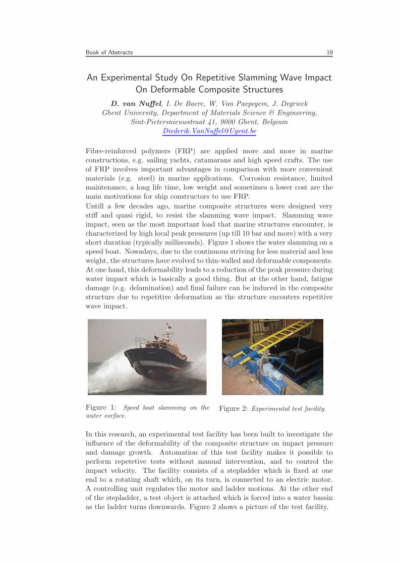
Untill a few decades ago, marine composite structures were designed verystiff and quasi rigid, to resist the slamming wave impact. Slamming waveimpact, seen as the most important load that marine structures encounter, ischaracterized by high local peak pressures (up till 10 bar and more) with a veryshort duration (typically millisconds). Figure 1 shows the water slamming on aspeed boat. Nowadays, due to the continuous striving for less material and lessweight, the structures have evolved to thin-walled and deformable components.At one hand, this deformability leads to a reduction of the peak pressure duringwater impact which is basically a good thing. But at the other hand, fatiguedamage (e.g. delamination) and final failure can be induced in the compositestructure due to repetitive deformation as the structure encouters repetitivewave impact.
Figure 1: Speed boat slamming on thewater surface.
Figure 2: Experimental test facility.
In this research, an experimental test facility has been built to investigate theinfluence of the deformability of the composite structure on impact pressureand damage growth. Automation of this test facility makes it possible toperform repetetive tests without manual intervention, and to control theimpact velocity. The facility consists of a stepladder which is fixed at oneend to a rotating shaft which, on its turn, is connected to an electric motor.A controlling unit regulates the motor and ladder motions. At the other endof the stepladder, a test object is attached which is forced into a water bassinas the ladder turns downwards. Figure 2 shows a picture of the test facility.

20 SAMPE Benelux
To create an initial idea about the influence of the deformability of thecomposite structure on impact pressures, tests with a full rigid cylinder anda hollow deformable cylinder have been performed and compared. In bothcases the pressure signals showed a very high and short pressure peak. Incontradiction with the prospections, the average peak pressure measured forthe deformable cylinder was comparable to the the peak pressure measured forthe rigid cylinder (5.17 bar versus 5.35 bar). However, conclusions can not bemade since there is too much scatter on the results (standard deviation: 2.31bar versus 1.51 bar). Too low sampling rate of the data acquisition system (51kHz) might be the cause for this scatter. New results with higher samplingrate have to be carried out to draw conclusions from the slamming tests.
Book of Abstracts 21
Manufacture Of Composite Sub-Structure Repairs For AircraftStructures
Bianca Nellen1, R.J.C. Creemers2, A. Beukers1, H.G. Jongeleen31 Delft University of Technology, Faculty of Aerospace Engineering,
Kluyverweg 1, 2629 HS Delft, The Netherlands2 National Aerospace Laboratory, Department of Aerospace VehiclesStructures Technology (AVST), P.O. Box 153, 8300AD Emmeloord3 Defence Material Organisation, Maritime and Unmanned AircraftDivision, Frederikkazerne, P.O.Box 90822, 2509 LV The Hague
For the Royal Netherlands Air Force (RNLAF) the F-16 replacement andNH-90 helicopter will be the first all-composite aircraft. When these aircraftbecome operational a Structural Repair Manual (SRM) is the guideline forrepair, which limits itself to small damages at undisturbed surfaces. In-houseknowledge on composite repair needs to be obtained by the RNLAF.The fighter-like F-16 replacement consists of a highly loaded monolithicstructure contrarily to the helicopter which consists of a less high loadedsandwich structure. For the fighter-like structure stealth capability andrepairing a high temperature BMI system make it very difficult to designrepairs without access to all data. The helicopter-like structure does not havestealth capability, does not need to be completely flush, is not made of a BMIsystem and more data is available to base the repair design upon. The lastadvantage leading to the decision to focus on the helicopter is that the NH-90becomes operational within the Netherlands in several months.Looking at a helicopter design this air vehicle roughly consists of twocomponents; a tail and a fuselage. The tail panels are only accessible fromthe outside with limited access from the inside. Fuselage panels are alwaysaccessible from both sides. The most difficult case from repair point of viewwas selected for this thesis, i.e. the generic benchmark panel based uponthe tail structure. This generic benchmark panel consists of two sandwichstructure sections chamfered down at the ends and in the middle to attach anL-shaped rib.
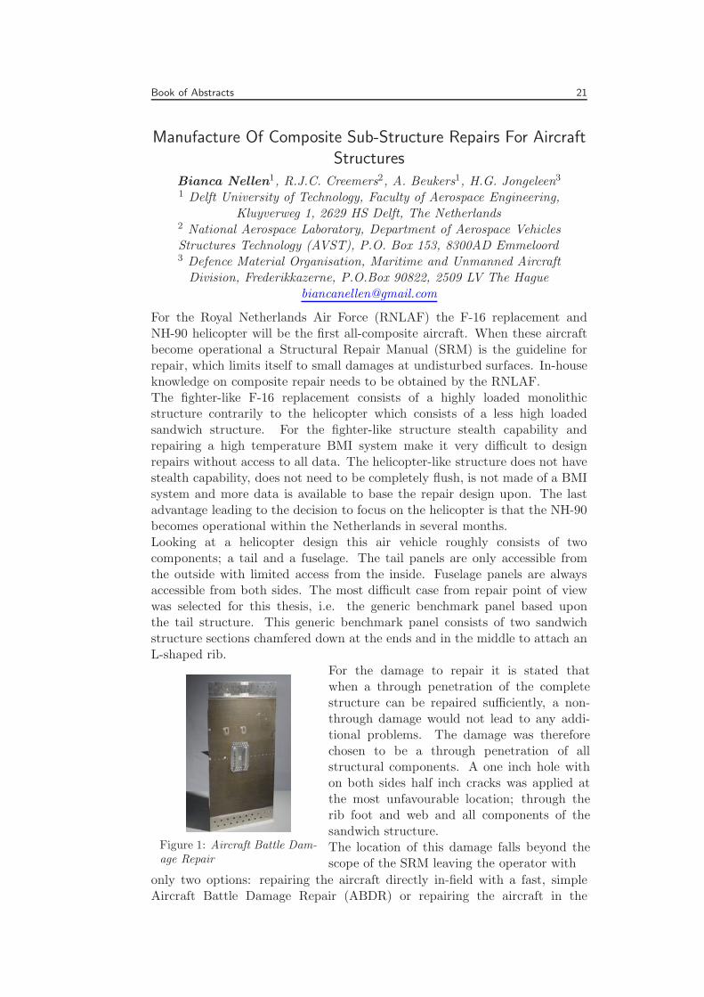
Figure 1: Aircraft Battle Dam-age Repair
For the damage to repair it is stated thatwhen a through penetration of the completestructure can be repaired sufficiently, a non-through damage would not lead to any addi-tional problems. The damage was thereforechosen to be a through penetration of allstructural components. A one inch hole withon both sides half inch cracks was applied atthe most unfavourable location; through therib foot and web and all components of thesandwich structure.The location of this damage falls beyond thescope of the SRM leaving the operator with
only two options: repairing the aircraft directly in-field with a fast, simpleAircraft Battle Damage Repair (ABDR) or repairing the aircraft in the
22 SAMPE Benelux
controlled environment with a sophisticated depot repair. ABDR can beperformed on different levels related to the situation the aircraft is at. Forthis thesis ABDR repair indicates the situation in which the aircraft is in-fieldbut with some time to place a patch.The goal of the ABDR repair is restoring strength in order to bring the aircraftback to an environment in which it can be repaired properly with an expedientor depot repair. For the ABDR repair an aluminium patch is designed andriveted against the damaged area. Again availability of time and severity ofthe situation defines whether improvements (i.e. adhesive film and crack stopholes) are applied. This repair showed first damage propagation during test at230 [kN] which is higher than the first damage occurring in an unrepaired panelwhich was observed at 190 [kN]. For final failure the value for the unrepairedpanel is 225 [kN] and for the ABDR repaired panel no final failure occurredbut it is expected to be close to 300 [kN].
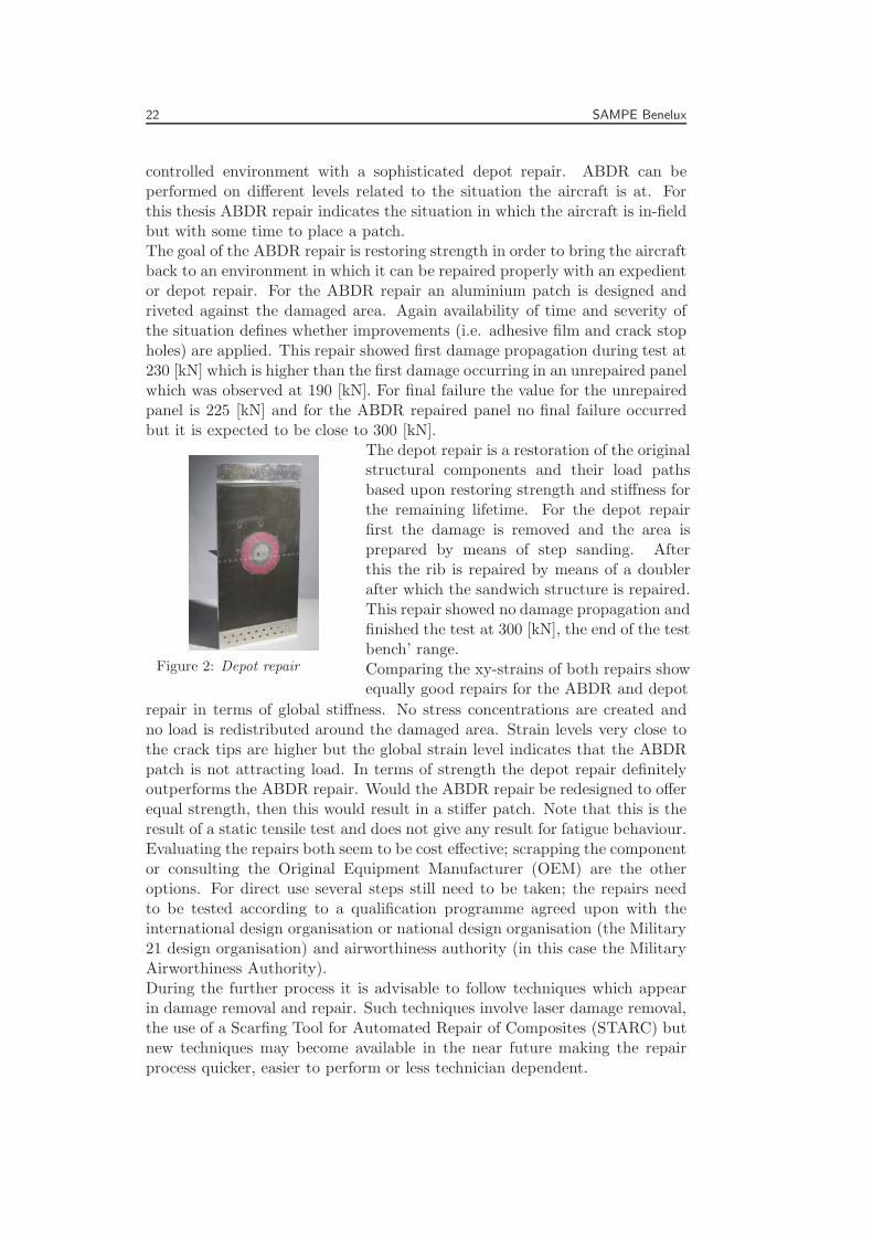
Figure 2: Depot repair
The depot repair is a restoration of the originalstructural components and their load pathsbased upon restoring strength and stiffness forthe remaining lifetime. For the depot repairfirst the damage is removed and the area isprepared by means of step sanding. Afterthis the rib is repaired by means of a doublerafter which the sandwich structure is repaired.This repair showed no damage propagation andfinished the test at 300 [kN], the end of the testbench’ range.Comparing the xy-strains of both repairs showequally good repairs for the ABDR and depot
repair in terms of global stiffness. No stress concentrations are created andno load is redistributed around the damaged area. Strain levels very close tothe crack tips are higher but the global strain level indicates that the ABDRpatch is not attracting load. In terms of strength the depot repair definitelyoutperforms the ABDR repair. Would the ABDR repair be redesigned to offerequal strength, then this would result in a stiffer patch. Note that this is theresult of a static tensile test and does not give any result for fatigue behaviour.Evaluating the repairs both seem to be cost effective; scrapping the componentor consulting the Original Equipment Manufacturer (OEM) are the otheroptions. For direct use several steps still need to be taken; the repairs needto be tested according to a qualification programme agreed upon with theinternational design organisation or national design organisation (the Military21 design organisation) and airworthiness authority (in this case the MilitaryAirworthiness Authority).During the further process it is advisable to follow techniques which appearin damage removal and repair. Such techniques involve laser damage removal,the use of a Scarfing Tool for Automated Repair of Composites (STARC) butnew techniques may become available in the near future making the repairprocess quicker, easier to perform or less technician dependent.
Book of Abstracts 23
Tow Mechanics: Improving The Accuracy Of DeformationModelling
B. Cornelissen, R. AkkermanUniversity of Twente, Faculty of Engineering Technology, Chair of
Production Technology, P.O. Box 217, 7500AE Enschede, The [email protected]
The mechanical properties of a continuous fibre reinforced polymer aredetermined to a large extent during the forming phase. The continuousfibrous tows deform geometrically. Knowledge of the tow orientation andtow deformation behaviour is essential to obtain the desired product qualityin terms of e.g. strength and impact performance. Modelling efforts have sofar been focused primarily on the macro (fabric) and meso (tow) scale [1,2].A physically based model of tow deformation which includes information onthe filament (micro) level can improve the accuracy of existing draping andforming simulation software.A set of five mechanisms is determined to describe the deformation of fibroustows:
1. Tension: A load is applied in axial direction with respect to the localtow or fibre axes.
2. Compaction: A load is applied perpendicular to the longitudinal axesof the tows or fibres.
3. Bending: A moment is induced in a tow or fibre section (the case oftow bending behaviour is described in previous work [3]).
4. Twist: Torsion due to a relative rotation between two locations isapplied along the longitudinal axis on the tows or fibres.
5. Shear: A load is induced by a relative displacement of two parallelplanes, which remain parallel during and after the displacement.
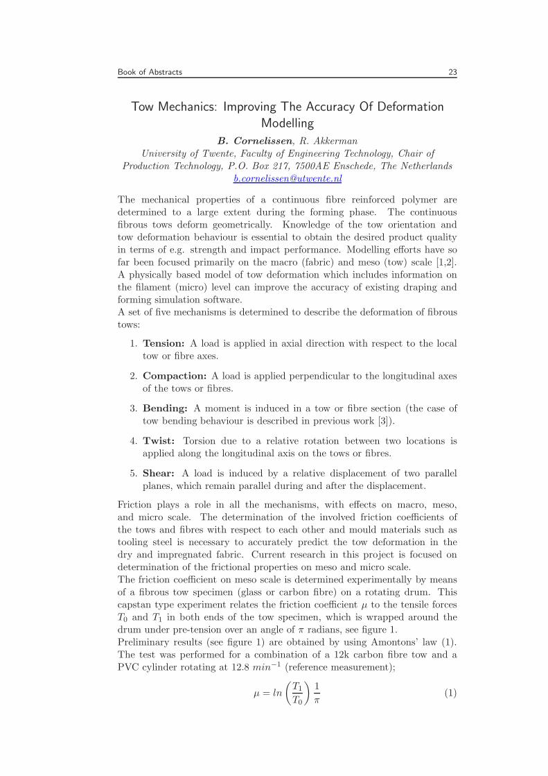
Friction plays a role in all the mechanisms, with effects on macro, meso,and micro scale. The determination of the involved friction coefficients ofthe tows and fibres with respect to each other and mould materials such astooling steel is necessary to accurately predict the tow deformation in thedry and impregnated fabric. Current research in this project is focused ondetermination of the frictional properties on meso and micro scale.The friction coefficient on meso scale is determined experimentally by meansof a fibrous tow specimen (glass or carbon fibre) on a rotating drum. Thiscapstan type experiment relates the friction coefficient μ to the tensile forcesT0 and T1 in both ends of the tow specimen, which is wrapped around thedrum under pre-tension over an angle of π radians, see figure 1.Preliminary results (see figure 1) are obtained by using Amontons’ law (1).The test was performed for a combination of a 12k carbon fibre tow and aPVC cylinder rotating at 12.8 min−1 (reference measurement);
μ = ln
(T1
T0
)1
π(1)
24 SAMPE Benelux
T0
T1
0 500 1000 1500 20000
0.05
0.1
0.15
0.2
0.25
0.3
0.35
Time [s]
�[N
/N]
0 500 1000 1500 20002
4
6
8
10
12
14
16
18
Time [s]
Forc
e[N
]
T0
T1
12k Carbon fibre tow on PVC
Figure 1: Outline of the capstan friction experiment and preliminary results
The dependence of the coefficient of friction on the rotational speed ofthe drum and the applied pre-tension on the tow specimen are subject ofinvestigation. Robins et al. [4] performed Capstan friction tests with singlecarbon fibres (among other materials) and did not find a dependence of thefriction coefficient on the rotational velocity of the drum. Nevertheless, thisindependence has to be verified for tow specimens as well, since the behaviourof those materials is not necessarily the same as that of the individual fibres.The sizing with which the tows are treated for better handling and adhesionto the matrix can play a significant role in the determination of the measuredfriction coefficient. The use of eq.(1), based on Amontons’ law, implies acontact area independent friction behaviour. This assumption will be verifiedfor the fibrous tow friction coefficient.
References
1 P. Boisse, B. Zouari, A. Gasser, Compos. Sci. Technol, 65, 429-436 (2005)
2 S.V. Lomov, I. Verpoest, Compos. Sci. Technol. 66, 919–933 (2006)
3 B. Cornelissen, R. Akkerman, Analysis of yarn bending behaviour, Proceedingsof the 17th International Conference on Composite Materials (ICCM 17),Edinburgh, Scotland, 2009
4 M.M. Robins, R.W. Rennell, R.D. Arnell, J. of Phys. D: Appl. Phys. 17, 1349–1360 (1984)
Book of Abstracts 25
Bamboo Fibre Thermoplastic Composites For StructuralApplications
E. Trujillo, L. Osorio, A.W. Van Vuure, I. VerpoestKatholieke Universiteit Leuven, Department of Metallurgy and MaterialsEngineering (MTM), Kasteelpark Arenberg 44, B-3001 Leuven, Belgium
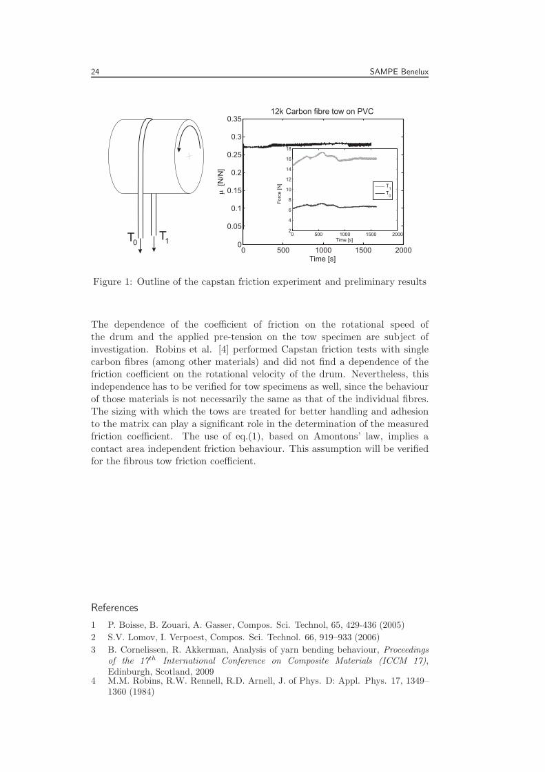
Natural fibres are becoming a real alternative for the transport sector thanksto their green nature, low density, and in some cases better specific mechanicalproperties (normalized to material density) than glass fibres. Thermalconductivity of natural fibres is low; therefore they make a good thermalbarrier. Low cost, inexhaustible supply and good environmental performance,make natural fibres possible substitutes to synthetic reinforcing fibre materials,especially for polymer matrix composites. In spite of these advantages, theirperformance with thermoplastic polymers has not been good enough andmore scientific research is needed to bring natural fibres to the market ofstructural components. Bamboo fibres represent one of the most attractivenatural fibres because of their availability and excellent mechanical properties;in this project, long bamboo (Guadua angustifolia Kunth) fibres are studiedto be used as reinforcement in both continuous thermoset and thermoplasticcomposite materials (Fig.1).
Figure 1: Unidirectional bamboo fibre composite with thermoplastic matrix.
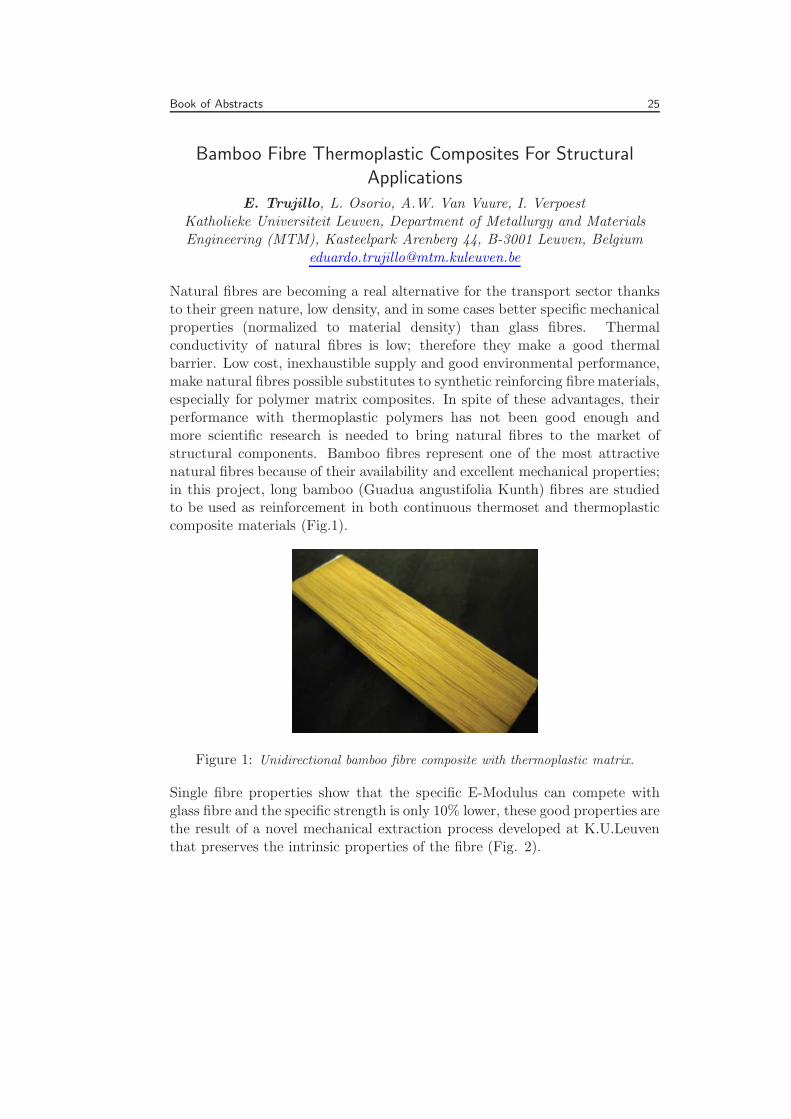
Single fibre properties show that the specific E-Modulus can compete withglass fibre and the specific strength is only 10% lower, these good properties arethe result of a novel mechanical extraction process developed at K.U.Leuventhat preserves the intrinsic properties of the fibre (Fig. 2).
26 SAMPE Benelux
Figure 2: Strength values vs extraction method for single bamboo fibres.
In spite of these properties, it was found that thermal degradation occursat a relatively low temperature. For UD bamboo/thermoplastic composites,several variables such as temperature, time of exposure to the consolidationtemperature, pressure and polymer type and rheological behavior are studiedin order to optimize the composite properties. The partial results show avery promise composite in comparison to other natural fibre thermoplasticcomposites.
Book of Abstracts 27
Using Microtomography And Numerical Predictions For TheInvestigation Of Failed Composites
S. Bakker1, H.E.N. Bersee1, J.P. Charles21 Delft University of Technology, Faculty of Aerospace Engineering,
Kluyverweg 1, 2629 HS Delft, The Netherlands2 Aix-Marseille Universite, Unimeca, 60 rue J. Curie, 13453 Marseille cedex
Materials comprised of two or more different materials with the propertiesof the new material being better than that of the components are calledcomposites. The application of composite materials in the aerospace industryis growing rapidly. The materials are known for having outstanding mechanicalproperties per unit weight, giving possibilities for lighter aircraft, leading tohigher efficiencies.With the presence of composite parts in aircraft the possibility of accidentsinvolving composite failures is created. Unfortunately the knowledge andexperience regarding failure analysis of composite structures is lacking behind.Failure analysis is strongly dependent on techniques originally developed formetals, like fractography, investigating the fracture surface. The problemis that in composites much information at the fracture surface is destroyedduring failure, making the failure analysis more difficult. Especially thediscrimination between static and fatigue failures is difficult.
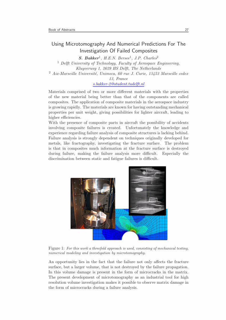
Figure 1: For this work a threefold approach is used, consisting of mechanical testing,numerical modeling and investigation by microtomography.
An opportunity lies in the fact that the failure not only affects the fracturesurface, but a larger volume, that is not destroyed by the failure propagation.In this volume damage is present in the form of microcracks in the matrix.The present development of microtomography as an industrial tool for highresolution volume investigation makes it possible to observe matrix damage inthe form of microcracks during a failure analysis.
28 SAMPE Benelux
The objective of this research is to investigate whether microtomographywith or without finite element modelling is a complementary tool to find thecause of fracture during post-mortem analyses. It is investigated whetherthere is a difference in damage behaviour observable by microtomography forcomposites failed under different loading and environmental conditions andwhether microtomography can be used to validate a finite element model basedon damage. For this research carbon fibre/epoxy and carbon fibre/PEEKunder static and fatigue loading are investigated for their behaviour at roomtemperature and at 100◦C.A difference in damage behaviour between a static-loading and a fatigue-loading history is observed by microtomography for unaged woven carbonfibre/epoxy and carbon fibre/PEEK tested at ambient temperature or at100◦C. Furthermore a difference between an ambient temperature and a 100◦Cloading condition is observed for unaged woven carbon fibre/epoxy tested infatigue. Since damage is observed by microtomography for unaged carbonfibre/epoxy tested under static or fatigue loading at room temperature, carbonfibre/epoxy tested under fatigue loading at 100◦C and carbon fibre/PEEKtested under static or fatigue loading at room temperature or at 100◦C,microtomography can be used to facilitate the validation of a finite elementmodel based on damage for these materials and conditions.Putting it all together it can be stated that microtomography can be useddirectly to distinguish between unaged woven carbon fibre/epoxy and carbonfibre/PEEK loaded statically and loaded in fatigue at ambient temperature orat 100◦C and can be used in combination with a finite element model basedon damage to validate a stress analysis in order to find the cause of fractureduring failure analyses in the cases where cracks can be found.
Book of Abstracts 29
Automated Double Cantilever Beam test system – A two-axismoving camera setup controlled by image analysis for crack
recognition
J. van de Zand, R. AkkermanUniversity of Twente, Faculty of Engineering Technology, Chair of
Production Technology, P.O. Box 217, 7500AE Enschede, The [email protected]
Composite materials are increasingly being used in structural components inindustries where weight and demanding mechanical properties are importantdesign criteria. To meet these high industrial standards the research anddevelopment in composite materials is a significant part of the industry.With the development of new materials and production methods, the needfor mechanical testing will be inevitable to define the mechanical propertiesof the composite material. The most common type of failure in laminatedcomposite materials is the separation of individual layers; delamination orinterlaminar fracture. The experimental determination of the interlaminarfracture toughness is generally done by the Double Cantilever Beam (DCB)test, for laminated composite materials first developed by Wilkins et al. [1].
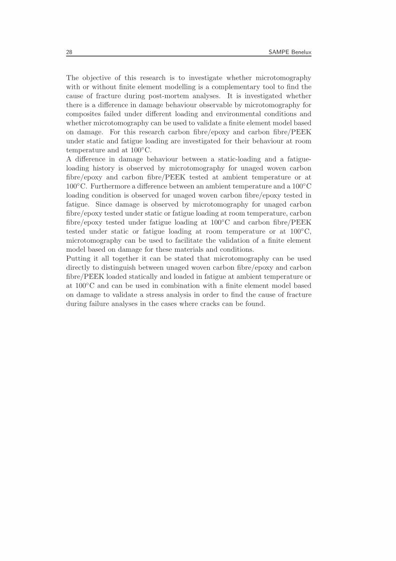
The standard configuration of DCB specimen is shown in fig. 1. Load blocksare bonded onto the surface of the unidirectional laminated specimen, to securethe application of the load in a straight line. The initial delamination isintroduced in the specimen by positioning a thin film at the mid-plane ofthe composite laminate during the production process. On one side edge ofspecimen a white paint is applied to ensure a high optical contrast betweenthe laminate and the growing crack front.
Figure 1: Three dimensional view (a)and schematic diagram (b) of a DCBspecimen.
When executing a DBC test, follow-ing the common standard ISO 15024[2], multiple parameters have to berecorded for the determination of thefracture toughness, GIc. Two datalines for the load and displacementof the specimen are directly extractedfrom the tensile testing machine andare relatively easy to record during theexperiment.
A third parameter is more complex to determine, this is the distance from theload line to the crack tip, the delamination length, x (fig. 1). This research isfocused on the identification and position of the crack tip.
The delamination length is currently determined at a limited number of points(typical 10-15) on the specimen by an observer moving a microscope alongwith the crack tip during the experiment. In the situation where no movingmicroscope is available the delamination length is measured in a post processat multiple pre-marked points on the specimen. Both manual methods havedisadvantages; in the accuracy of the determination of the crack length, requirea skilled observer and are time-consuming. To exclude the manual observationof the delamination length and thereby increase the accuracy and repeatability
30 SAMPE Benelux
of the test an automated test system is designed.
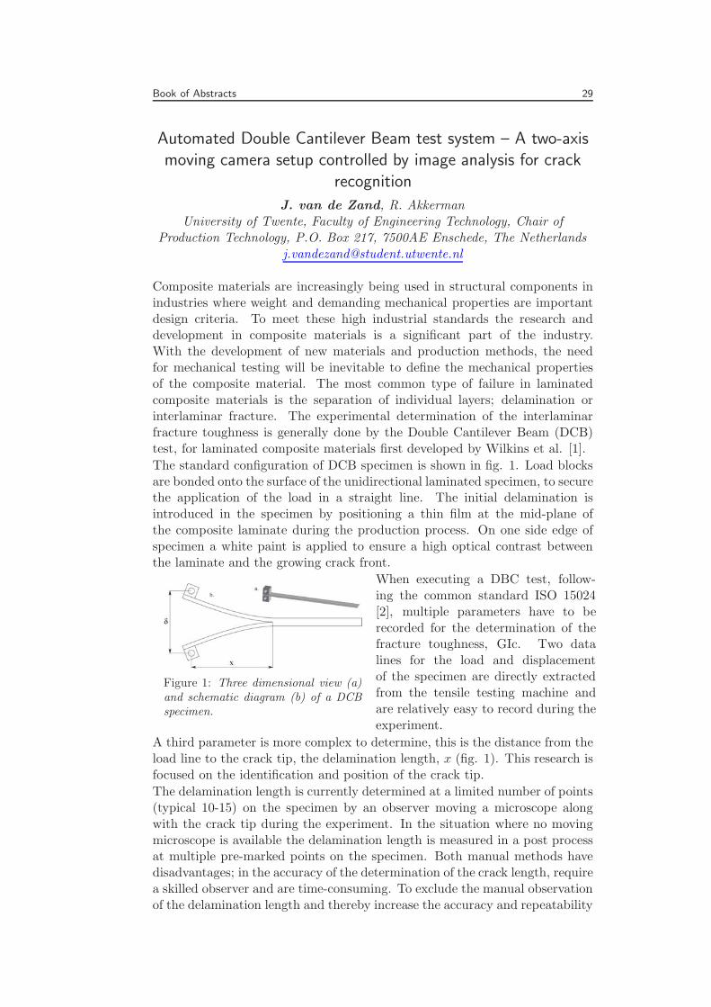
Figure 2: Acquired and processed im-age of a DCB specimen at the cracktip.
The hardware of the system consists ofa CCD camera mounted on a two-axislinear actuator controlled by a steppermotor for each direction. This setup ismounted behind the tensile tester per-pendicular to the mounted specimen.With the macro zoom lens fitted onthe camera a meso-scale image of theside edge of the specimen is acquiredwith an image size of approximatelyfour millimeters in height, see fig. 2for a typical acquired image.
The processing of the acquired images is done real-time in the NI Labviewplatform at a rate of one frame per second. In this cycle the individual imageis converted to a binary image by a threshold operation and a Region OfInterest (ROI) is defined. Within the ROI an object detection is executed,combined with the set boundary conditions for ia. minimal object size andcontrast ratio, multiple dark objects are identified. In fig. 2 the red objectsare numbered within the green ROI square. The object with the largest x-coordinate is selected as the location of the crack initiation. The coordinatesof the crack tip are used to update the camera position every cycle. Thedelamination length is obtained by the current camera position and the cracktip coordinates in the acquired image.Experiments with the operational system have been performed with ther-moplastic composite (CF/PEI) laminates with good results. A significantimprovement is made compared to the manual analysis; the interlaminarfracture toughness is determined at every data point (1Hz) and is not limited toa number of manual observations. The automated system has been comparedto a manual analysis for a single specimen, first automatically tested and post-processed manually. The automated system has a tendency to underestimatethe delamination length, caused by the conversion to a binary image in thefirst step of the process. This is related to the limited number of availablepixels of the used camera compared to the height of the crack opening at thetip. The height of the crack-opening near the crack tip is possibly less thanone pixel and therefore information is lost by the threshold operation.Continuous research will involve performing automated DCB experimentson thermoplastic laminates, the acquired data will be used to improve andquantify the system. The automated DCB test system should contribute tothe reliable and time efficient execution of delamination toughness experimentsin academic and industrial environments.
References
1 D.J. Wilkens, J.R. Eisenmann, R.A. Camin, W.S. Margolis, and R.A. Benson,ASTM STP-775 (1982)
2 ISO 15024, ISO Central, (2001)
Book of Abstracts 31
Numerical Investigation And Comparison Of Slamming LoadsOn Rigid And Deformable Cylindrical Structures
K.S. Vepa1, W. Van Paepegem1, J. Degroote2, J. Vierendeels21 Ghent University, Department of Materials Science and Engineering,
Sint-Pietersnieuwstraat 41, 9000, Ghent, Belgium2 Ghent University, Department of Flow, Heat and Combustion Mechanics,
Sint-Pietersnieuwstraat 41, 9000 Ghent, [email protected]
Keywords: Slamming, rigid cylinder, deformable composite cylinder, fluid-structure interaction, Arbitrary Lagrangian-Eulerian (ALE)
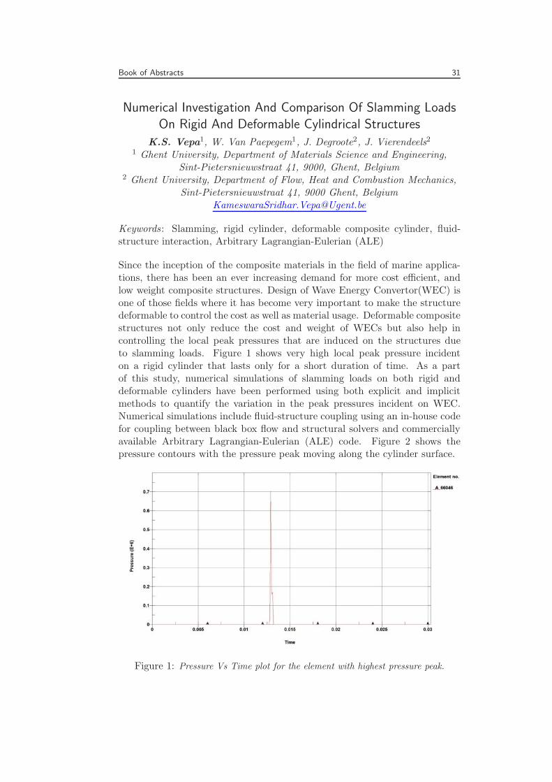
Since the inception of the composite materials in the field of marine applica-tions, there has been an ever increasing demand for more cost efficient, andlow weight composite structures. Design of Wave Energy Convertor(WEC) isone of those fields where it has become very important to make the structuredeformable to control the cost as well as material usage. Deformable compositestructures not only reduce the cost and weight of WECs but also help incontrolling the local peak pressures that are induced on the structures dueto slamming loads. Figure 1 shows very high local peak pressure incidenton a rigid cylinder that lasts only for a short duration of time. As a partof this study, numerical simulations of slamming loads on both rigid anddeformable cylinders have been performed using both explicit and implicitmethods to quantify the variation in the peak pressures incident on WEC.Numerical simulations include fluid-structure coupling using an in-house codefor coupling between black box flow and structural solvers and commerciallyavailable Arbitrary Lagrangian-Eulerian (ALE) code. Figure 2 shows thepressure contours with the pressure peak moving along the cylinder surface.
Figure 1: Pressure Vs Time plot for the element with highest pressure peak.

32 SAMPE Benelux
Figure 2: Pressure contour at a given time step.
Book of Abstracts 33
Self-Reinforcing High performance Polymer Coatings ForAerospace Applications
G.L. Guerriero, C. de Ruijter, R. C. Alderliesten, R. BenedictusDelft University of Technology, Faculty of Aerospace Engineering, StructuralIntegrity and Engineering Mechanics, Kluyverweg 1, 2629 HS Delft, The
Keywords: Liquid crystalline polymers, thermoset, adhesion, chemical resis-tance, thermal spray.
Commercial Liquid crystalline polymers (LCPs) are known for their outstand-ing properties compared to other high performance polymers. These propertiesinclude superior fracture toughness, dimensional stability, chemical resistanceand barrier properties over a wide temperature range [1]. These propertiesare mainly due to the formation of a highly ordered mesomorphic phase;a phenomenon known as self-reinforcement. Commercial LCPs have beenapplied in (for example) bulletproof jackets and high precision injected partsfor electronic devices. As LCPs are chemically inert, the adhesion strengthwhen adhered to a metal layer is usually quite low. Therefore, they have beenunacknowledged as coating materials. VectraTM is one of the most studiedthermoplastic LCPs. Several authors have focused on the enhancement ofits adhesion for applications like packaging or as printed circuit boards [2],with limited results. In addition, they can only be dissolved using hazardousacids, and thus, coatings can not be applied from solution. Therefore, meltprocessing or powder coating techniques need to be considered.
Novel liquid crystalline thermosets (LCT) consist of low molecular weightVectra A type backbones (oligomer) terminated with reactive aryl-ethynylgroups. Like traditional thermoplastics, these LCTs can be melt-processedwithin a wide temperature window. Further heating above the cure onsettemperature induce chain extension and crosslink chemistries compatiblewith the liquid crystalline mesophase, which fix the structure and form atridimensional polymer network [3].
Our objective is to develop a coating process suitable for these new highperformance LCTs, and to study their performance in relation to specificrequirements from aerospace applications. LCT coating layers with a thicknessof 25μm and 80μm were applied on grid-blasted Aluminum by melt pressingthe polymer inside a mold. Thermal, topographic and tribological propertiesof these coatings were investigated. The effect of moisture and aggressiveenvironments on the mechanical and physical properties of the coating was alsostudied and compared to the performance of commercial LCPs. The findingsshow that these LCTs exhibit the chemical resistance of traditional LCPs, butwith high adhesion strengths similar to those of structural adhesives.
In addition, our research also focuses on the application of LCT coatingsby thermal spray, a versatile coating technique compatible with industrialproduction lines.

34 SAMPE Benelux
References
1 C. Noel et. al., Prog. Polym. Sci., 16, 55-110 (1991)
2 Y. Kurihara et. al. , J. App. Polym. Sci., 108, 85-92 (2008)
3 A. Knijnenberg et. al., Macromolecules, 39, 6936-6943 (2006)
Book of Abstracts 35
Energy Release Rate Concept Validation On DelaminationBehaviour Of A CFRP Wet Lay-Up Scarf Joint Repair
T. van Vugt, C.D. Rans, R. AnderliestenDelft University of Technology, Faculty of Aerospace Engineering,
Kluyverweg 1, 2629 HS Delft, The [email protected]
Today, aerospace composite structures seem to be certified according toapproaches similar to safe life, using no growth concepts, which means asignificant drawback in terms of optimal design and structural weight. Tofully explore the potential of these types of materials, similar damage toleranceapproaches as being developed for metallic structures should be developed forcomposite materials. Another driver to obtain knowledge and understandingof fatigue and damage tolerance properties of composite materials should besafety. Without understanding and the ability to predict the damage growthmechanisms of a material, proper safe application will not be possible.Recently, a generic concept has been proposed to predict delamination growthwhich is based on the Energy Release Rate (ERR). The first validationactivities on fibre-metal materials show promising results. The purpose of thisstudy is to show that this generic ERR based concept is also valid for compositeapplications. Hereto a specific composite application has been selected forwhich the validation will be performed.The selected application is a 2 dimensional representation of a CFRP wet lay-up scarf joint repair. That is a joint between a pre-impregnated plain weavecarbon fibre fabric 180oC curing epoxy system and a wet lay-up system ofidentical fabric with a room temperature curing epoxy. Both laminates havelay-up [[±45,90]3]S and the repair plies are applied such that all plies end atthe scarf interface surface.To predict the delamination behaviour of the selected application an analyticalERR based model is proposed which will be validated experimentally. Therelation between delamination growth (dadN) and the effective ERR (ΔGeff )has been determined by experiments with mode I and mode II type specimen.For mode I the standard DCB test has been used. Mode II has been testedusing a tensile type test at which two butt-jointed plates are connected bysymmetrical application of continuous plies at both sides at which the initialdelamination has an H-shape.It will be shown how the proposed approach agrees with the experiments. Withthis approach one should be able to predict delamination behaviour requiringan analytical ERR model and relatively simple mode I/II tests only.

36 SAMPE Benelux
Book of Abstracts 37
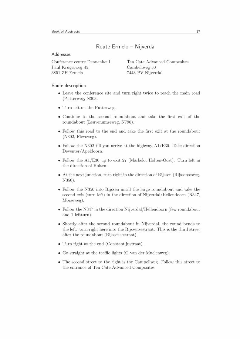
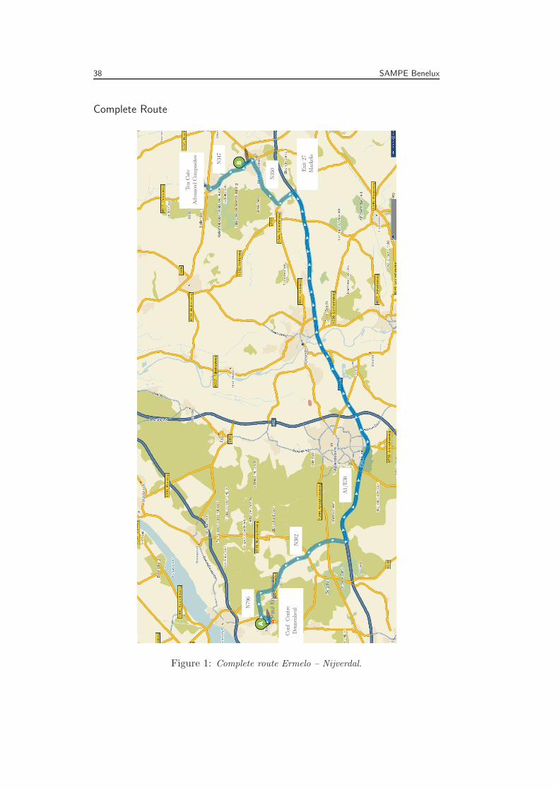
Route Ermelo – Nijverdal
Addresses
Conference centre DennenheulPaul Krugerweg 453851 ZH Ermelo
Ten Cate Advanced CompositesCambellweg 307443 PV Nijverdal
Route description
• Leave the conference site and turn right twice to reach the main road(Putterweg, N303.
• Turn left on the Putterweg.
• Continue to the second roundabout and take the first exit of theroundabout (Leuvenumseweg, N796).
• Follow this road to the end and take the first exit at the roundabout(N302, Flevoweg).
• Follow the N302 till you arrive at the highway A1/E30. Take directionDeventer/Apeldoorn.
• Follow the A1/E30 up to exit 27 (Markelo, Holten-Oost). Turn left inthe direction of Holten.
• At the next junction, turn right in the direction of Rijssen (Rijssenseweg,N350).
• Follow the N350 into Rijssen untill the large roundabout and take thesecond exit (turn left) in the direction of Nijverdal/Hellendoorn (N347,Morseweg).
• Follow the N347 in the direction Nijverdal/Hellendoorn (few roundaboutand 1 leftturn).
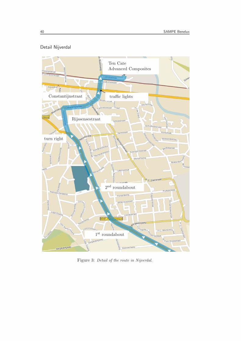
• Shortly after the second roundabout in Nijverdal, the round bends tothe left: turn right here into the Rijssensestraat. This is the third streetafter the roundabout (Rijssensestraat).
• Turn right at the end (Constantijnstraat).
• Go straight at the traffic lights (G van der Muelenweg).
• The second street to the right is the Campellweg. Follow this street tothe entrance of Ten Cate Advanced Composites.
38 SAMPE Benelux
Complete Route
Conf.Centre
DennenheulN796
N302
A1/E30
Exit27
Markelo
N350
N347
Ten
Cate
AdvancedCom
posites
Figure 1: Complete route Ermelo – Nijverdal.

Book of Abstracts 39
Detail Ermelo
Conf.Centre
Dennenheul
Putterweg
N796
Roundabout
N302
Figure 2: Detail of the route in Ermelo.
40 SAMPE Benelux
Detail Nijverdal
1st roundabout
2nd roundabout
turn right
Rijssensestraat
traffic lightsConstantijnstraat
Ten CateAdvanced Composites
Figure 3: Detail of the route in Nijverdal.
Book of Abstracts 41
Winners
The jury of the 8th Sampe Benelux Student Meeting is pleased to announcedthat the prize for the best presentation is awarded to:
Gustavo Guerreiro
Delft University of Technology,Faculty of Aerospace EngineeringStructural Integrity and Engineering Mechanics
He is invited to represent the Benelux at the Sampe Europe Student Confer-ence preceding the 31st Sampe Europe International Technical Conference.His abstract can be found on page 33 of this Book of Abstracts.
Secondly, the jury has decided to propose:
Eduardo Trujillo
Katholieke Universiteit LeuvenDepartment of Metallurgy and Materials Engineering
as a candidate for the JEC award. If granted, he will also participate in theSampe Europe Student Conference. His abstract can be found on page 25of this Book of Abstracts.
The jury congratulates the winners and wishes them good luck at the SampeEurope Student Conference.
Richard Loendersloot
On behalf of the Sampe Benelux Student meeting jury:Adrie KwakernaakAriean KoelewijnJeroen de VriesMarcus KremersPeter JoosseArnt Offringa

42 SAMPE Benelux