SAMIA Italia srl - Tel+39 039/6065920 Fax:+39 … OUTLINE...Samia® Italia Product Catalogue Samia...
54
Samia ® Italia Product Catalogue Samia ® Italia Srl is an independent Organization is NOT being associated to any other entity showing same Brand Name and/or Logo Tel:+39 039/6065920 Fax:+39 039/6064548 [email protected] WWW.SAMIASRL.COM Samia ® Italia Srl Via Bergamo , 39 23807 Merate (LC) - Italy
Transcript of SAMIA Italia srl - Tel+39 039/6065920 Fax:+39 … OUTLINE...Samia® Italia Product Catalogue Samia...
Samia ® Italia Product Catalogue
Samia® Italia Srl is an independent Organization is NOT being associated to any other entity showing same Brand Name and/or Logo
Tel:+39 039/6065920 Fax:+39 039/6064548
[email protected] WWW.SAMIASRL.COM
Samia® Italia SrlVia Bergamo , 39
23807 Merate (LC) - Italy
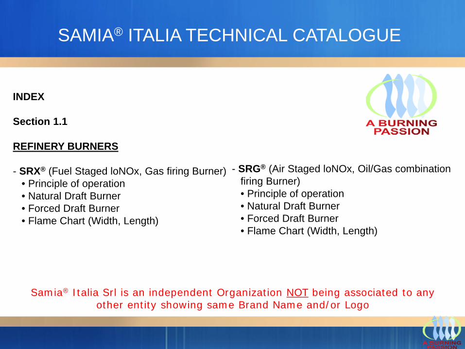
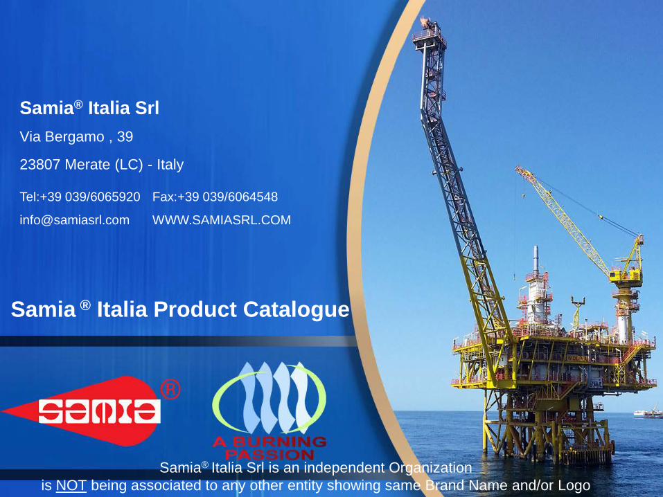
INDEX
Section 1.1
REFINERY BURNERS
- SRX® (Fuel Staged loNOx, Gas firing Burner)• Principle of operation• Natural Draft Burner• Forced Draft Burner • Flame Chart (Width, Length)
- SRG® (Air Staged loNOx, Oil/Gas combinationfiring Burner)• Principle of operation• Natural Draft Burner • Forced Draft Burner • Flame Chart (Width, Length)
Samia® Italia Srl is an independent Organization NOT being associated to any other entity showing same Brand Name and/or Logo
SAMIA® ITALIA TECHNICAL CATALOGUE
INDEX
Section 1.2
REFINERY BURNERS (New Generation)
- Cone-Mod Design (CMD)- Principle of operation- Natural Draft Burner - Forced Draft Burner
- Swirl LoNOx Design (SLD)- Principle of operation- Natural Draft Burner - Forced Draft Burner
- Ultra Low NOx Design (SULND)-Principle of operation-Natural Draft Burner -Forced Draft Burner
SAMIA® ITALIA TECHNICAL CATALOGUE
- REGENERATIVE COMBUSTION
INDEX
Section 1.3
REFINERY BURNERS Services
SAMIA® ITALIA TECHNICAL CATALOGUE
Samia® Italia provides the following services:
Surveys / Modification Feasibility Studies / Retrofitting Installation Supervision Revamping / Repairs / Upgrade Spares / Modification Start up
Section 2
FLARES
- OVERVIEW• Achievable Emission Limits/Reductions• Typical Industrial Applications• Emission Stream Characteristics• Emission Stream Pre-treatment Requirements• Theory of Operation• Steam-Assisted Flare Packages• Air-assisted Flare Packages• Sonic Flare Packages (Single and MULTIARMS Solutions)• Ground Flare System (Multi-Point and Enclosed Ground Flares)• Advantages• Other Considerations
Section 2.1
FLARE ASSEMBLIES
• Self-Supported• Guy-Supported• Derrick-Supported• Off-Shore• Mobile Flares (Non-stationary)• Ground Flare (Enclosed/Open)
Section 2.2
FLARE TIPS
• Barrel Flare Tip• Steam-Assisted Flare Tip• Air-Assisted Flare Tip• Sonic/Multipoint Flare Tips
Section 2.3
FLARE SEALS
• Diode Pinecone Seal (Velocity Seal)• Molecular Seal• Liquid Seal
Section 2.4
FLARE SERVICES
Section 3
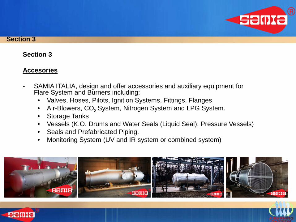
Accesories
- SAMIA ITALIA, design and offer accessories and auxiliary equipment for Flare System and Burners including:
• Valves, Hoses, Pilots, Ignition Systems, Fittings, Flanges• Air-Blowers, CO2 System, Nitrogen System and LPG System.• Storage Tanks • Vessels (K.O. Drums and Water Seals (Liquid Seal), Pressure Vessels)• Seals and Prefabricated Piping.• Monitoring System (UV and IR system or combined system)
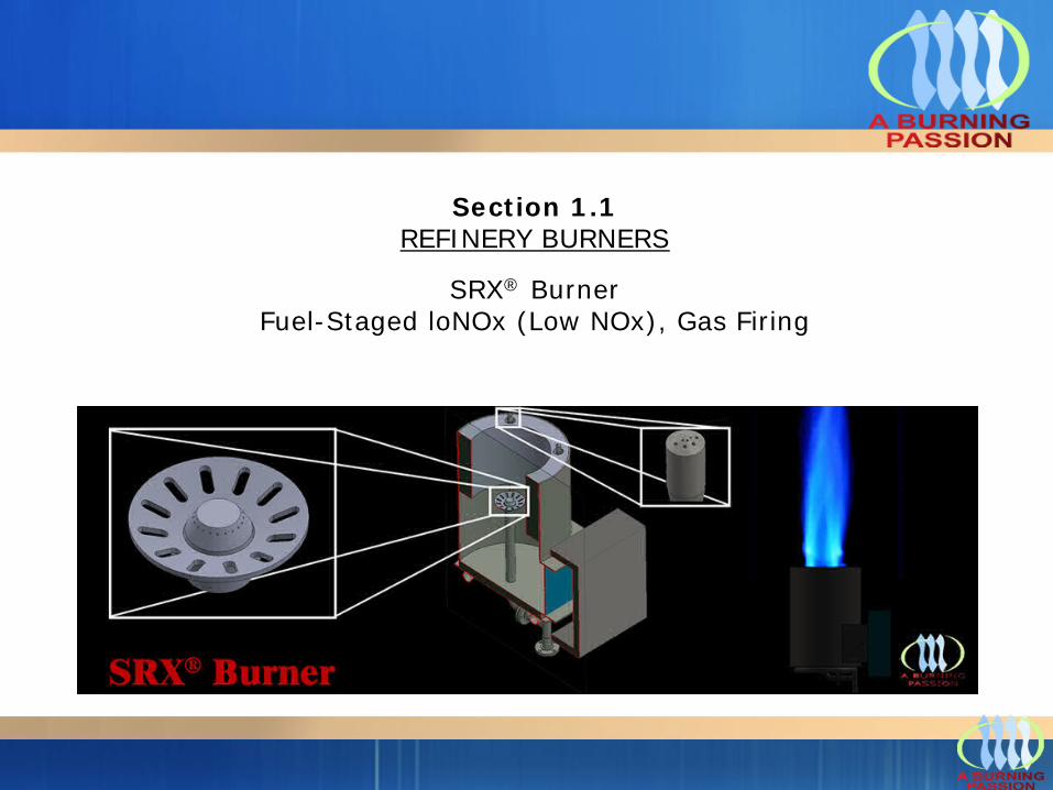
Section 1.1REFINERY BURNERS
SRX® Burner Fuel-Staged loNOx (Low NOx), Gas Firing
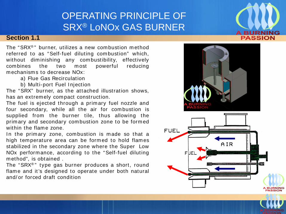
The “SRX®” burner, utilizes a new combustion methodreferred to as “Self-fuel diluting combustion” which,without diminishing any combustibility, effectivelycombines the two most powerful reducingmechanisms to decrease NOx:
a) Flue Gas Recirculationb) Multi-port Fuel Injection
The “SRX” burner, as the attached illustration shows,has an extremely compact construction.The fuel is ejected through a primary fuel nozzle andfour secondary, while all the air for combustion issupplied from the burner tile, thus allowing theprimary and secondary combustion zone to be formedwithin the flame zone.In the primary zone, combustion is made so that ahigh temperature area can be formed to hold flamesstabilized in the secondary zone where the Super LowNOx performance, according to the “Self-fuel dilutingmethod”, is obtained .The “SRX®” type gas burner produces a short, roundflame and it’s designed to operate under both naturaland/or forced draft condition
OPERATING PRINCIPLE OF SRX® LoNOx GAS BURNER
Section 1.1
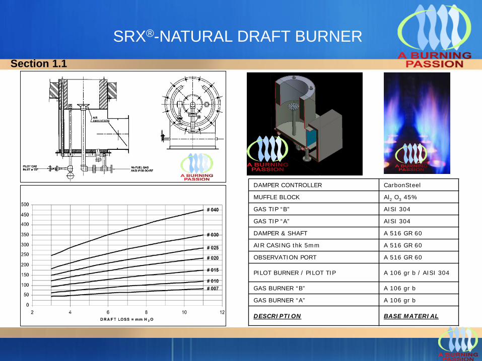
SRX®-NATURAL DRAFT BURNER
DAMPER CONTROLLER CarbonSteel
MUFFLE BLOCK Al2 O3 45%
GAS TIP “B” AISI 304
GAS TIP “A” AISI 304
DAMPER & SHAFT A 516 GR 60
AIR CASING thk 5mm A 516 GR 60
OBSERVATION PORT A 516 GR 60
PILOT BURNER / PILOT TIP A 106 gr b / AISI 304
GAS BURNER “B” A 106 gr b
GAS BURNER “A” A 106 gr b
DESCRIPTION BASE MATERIAL
Section 1.1
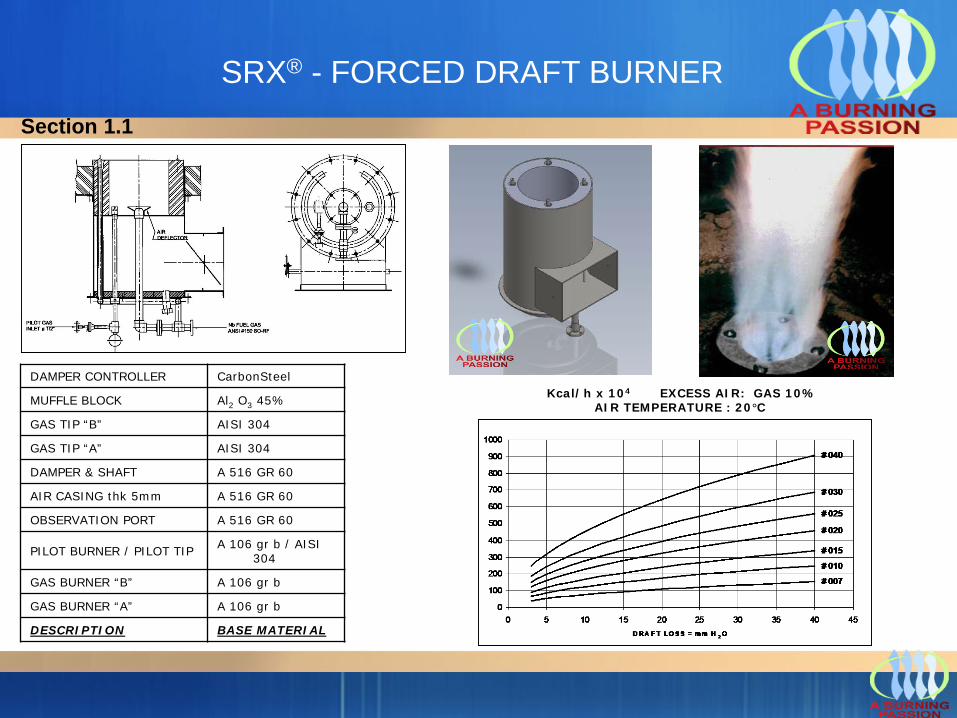
SRX® - FORCED DRAFT BURNER
Kcal/h x 104 EXCESS AIR: GAS 10% AIR TEMPERATURE : 20°C
DAMPER CONTROLLER CarbonSteel
MUFFLE BLOCK Al2 O3 45%
GAS TIP “B” AISI 304
GAS TIP “A” AISI 304
DAMPER & SHAFT A 516 GR 60
AIR CASING thk 5mm A 516 GR 60
OBSERVATION PORT A 516 GR 60
PILOT BURNER / PILOT TIP A 106 gr b / AISI 304
GAS BURNER “B” A 106 gr b
GAS BURNER “A” A 106 gr b
DESCRIPTION BASE MATERIAL
Section 1.1
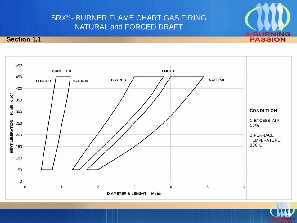
SRX® - BURNER FLAME CHART GAS FIRING NATURAL and FORCED DRAFT
DIAMETER
FORCED
LENGHT
NATURALFORCED NATURAL
0
50
100
150
200
250
300
350
400
450
500
0 1 2 3 4 5 6
DIAMETER & LENGHT = Meter
HEAT
LIB
ERAT
ION
= Kc
al/h
x 1
04
CONDITION
1.EXCESS AIR: 10%
2.FURNACE TEMPERATURE: 800°C
Section 1.1
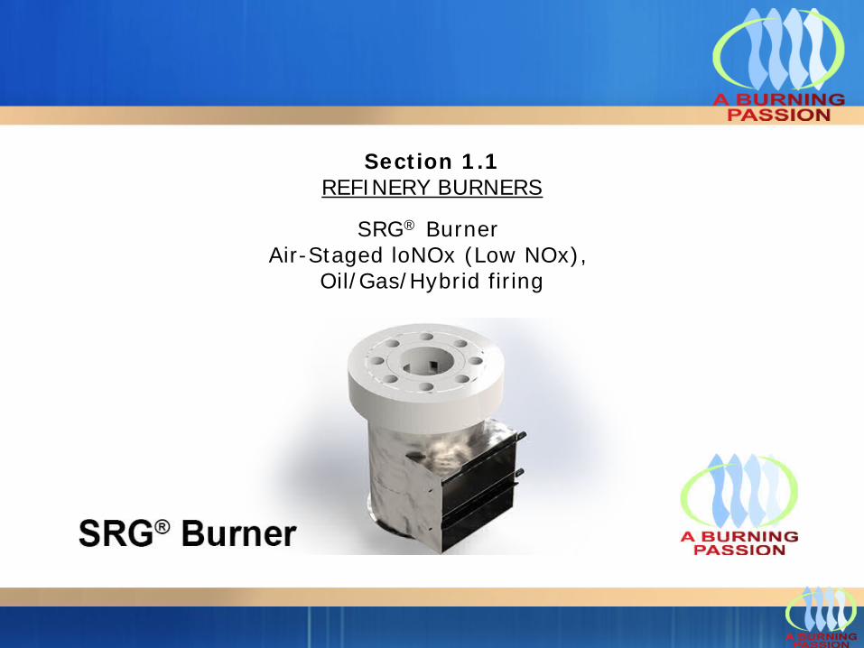
Section 1.1REFINERY BURNERS
SRG® Burner Air-Staged loNOx (Low NOx),
Oil/Gas/Hybrid firing
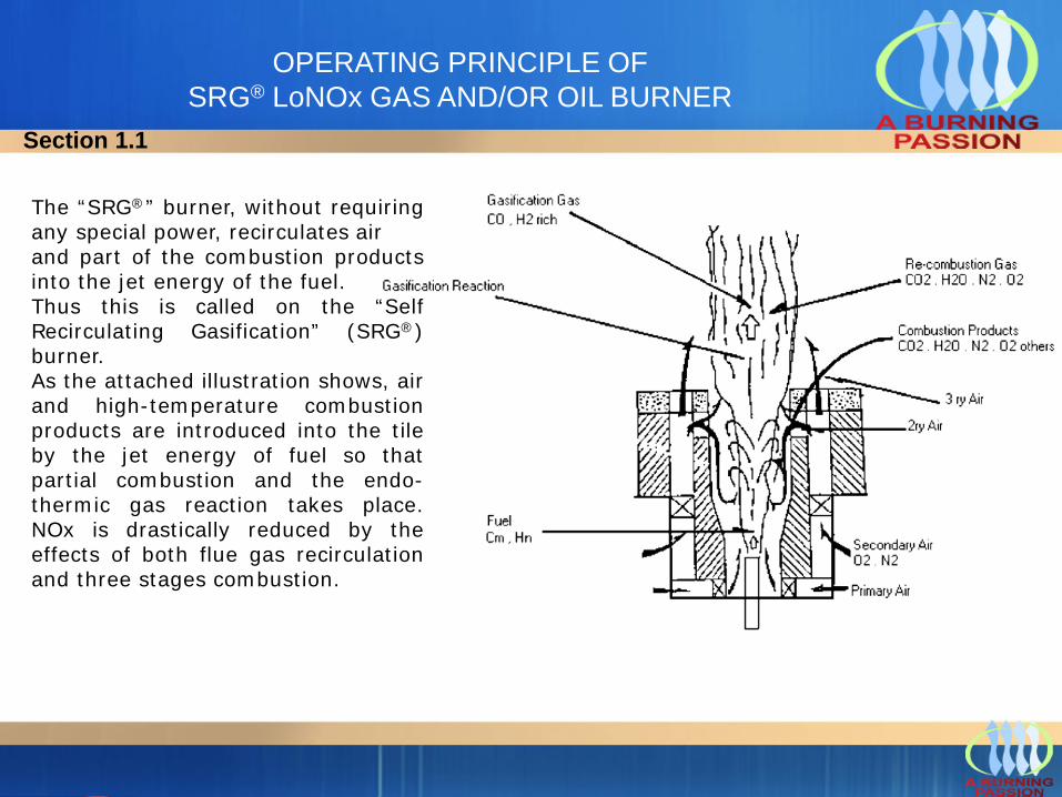
OPERATING PRINCIPLE OF SRG® LoNOx GAS AND/OR OIL BURNER
The “SRG®” burner, without requiringany special power, recirculates airand part of the combustion productsinto the jet energy of the fuel.Thus this is called on the “SelfRecirculating Gasification” (SRG®)burner.As the attached illustration shows, airand high-temperature combustionproducts are introduced into the tileby the jet energy of fuel so thatpartial combustion and the endo-thermic gas reaction takes place.NOx is drastically reduced by theeffects of both flue gas recirculationand three stages combustion.
Section 1.1
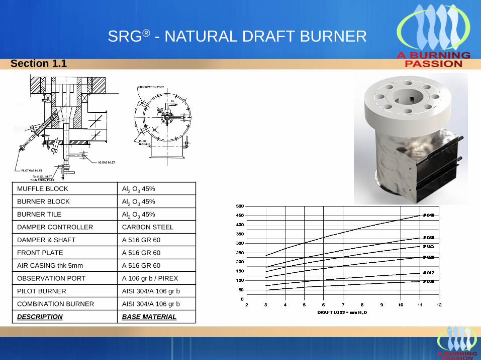
SRG® - NATURAL DRAFT BURNER
MUFFLE BLOCK Al2 O3 45%
BURNER BLOCK Al2 O3 45%
BURNER TILE Al2 O3 45%
DAMPER CONTROLLER CARBON STEEL
DAMPER & SHAFT A 516 GR 60
FRONT PLATE A 516 GR 60
AIR CASING thk 5mm A 516 GR 60
OBSERVATION PORT A 106 gr b / PIREX
PILOT BURNER AISI 304/A 106 gr b
COMBINATION BURNER AISI 304/A 106 gr b
DESCRIPTION BASE MATERIAL
Section 1.1
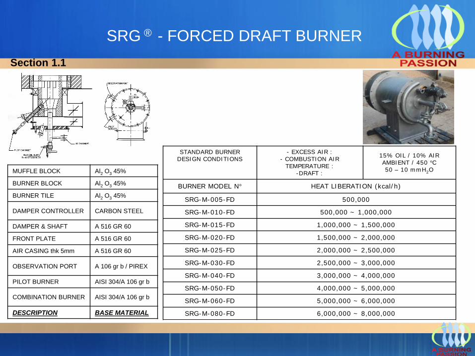
SRG ® - FORCED DRAFT BURNER
STANDARD BURNER DESIGN CONDITIONS
- EXCESS AIR :- COMBUSTION AIR
TEMPERATURE : -DRAFT :
15% OIL / 10% AIRAMBIENT / 450 °C50 – 10 mmH2O
BURNER MODEL N° HEAT LIBERATION (kcal/h)
SRG-M-005-FD 500,000
SRG-M-010-FD 500,000 ~ 1,000,000
SRG-M-015-FD 1,000,000 ~ 1,500,000
SRG-M-020-FD 1,500,000 ~ 2,000,000
SRG-M-025-FD 2,000,000 ~ 2,500,000
SRG-M-030-FD 2,500,000 ~ 3,000,000
SRG-M-040-FD 3,000,000 ~ 4,000,000
SRG-M-050-FD 4,000,000 ~ 5,000,000
SRG-M-060-FD 5,000,000 ~ 6,000,000
SRG-M-080-FD 6,000,000 ~ 8,000,000
MUFFLE BLOCK Al2 O3 45%
BURNER BLOCK Al2 O3 45%
BURNER TILE Al2 O3 45%
DAMPER CONTROLLER CARBON STEEL
DAMPER & SHAFT A 516 GR 60
FRONT PLATE A 516 GR 60
AIR CASING thk 5mm A 516 GR 60
OBSERVATION PORT A 106 gr b / PIREX
PILOT BURNER AISI 304/A 106 gr b
COMBINATION BURNER AISI 304/A 106 gr b
DESCRIPTION BASE MATERIAL
Section 1.1
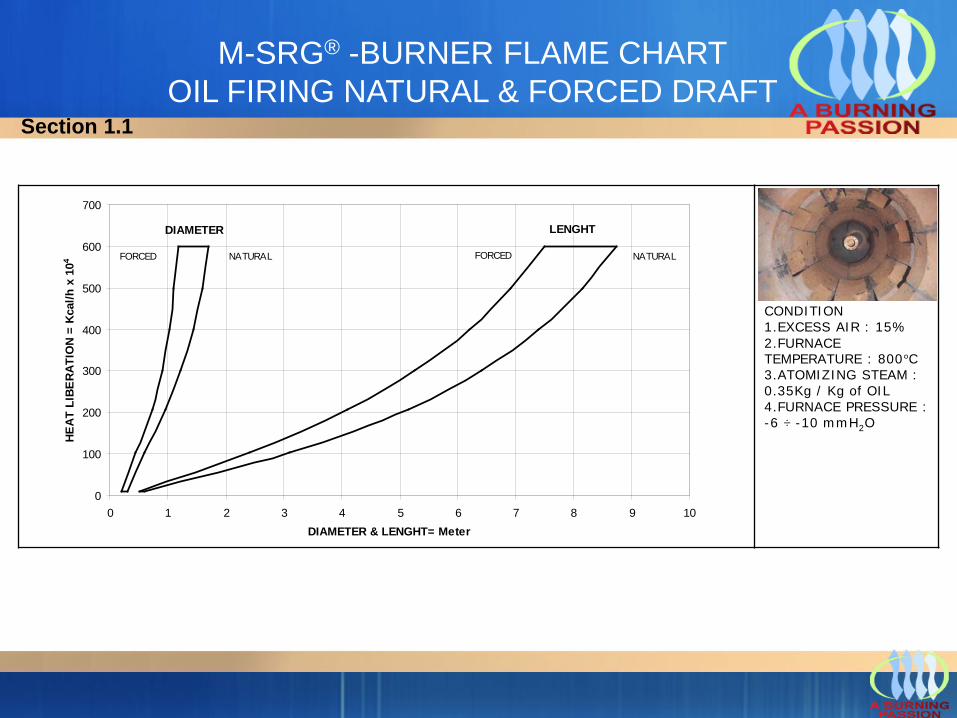
M-SRG® -BURNER FLAME CHART OIL FIRING NATURAL & FORCED DRAFT
DIAMETER LENGHT
NATURALFORCEDNATURALFORCED
0
100
200
300
400
500
600
700
0 1 2 3 4 5 6 7 8 9 10DIAMETER & LENGHT= Meter
HEAT
LIB
ERAT
ION
= Kc
al/h
x 1
04
CONDITION1.EXCESS AIR : 15%2.FURNACE TEMPERATURE : 800°C3.ATOMIZING STEAM : 0.35Kg / Kg of OIL4.FURNACE PRESSURE :-6 ÷ -10 mmH2O
Section 1.1
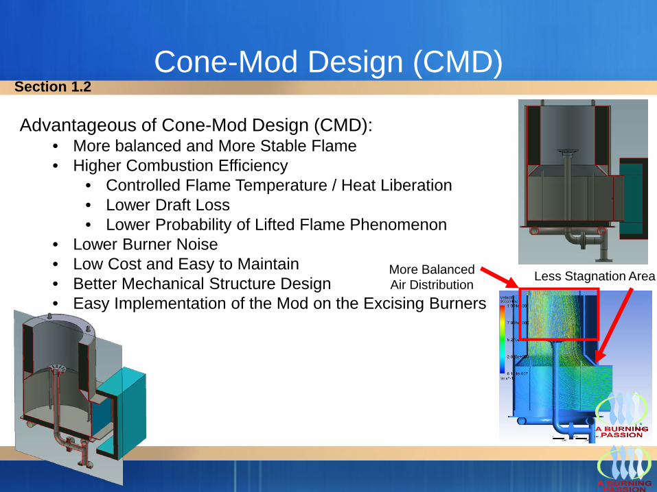
Cone-Mod Design (CMD)
More Balanced Air Distribution Less Stagnation Area
Advantageous of Cone-Mod Design (CMD):• More balanced and More Stable Flame• Higher Combustion Efficiency
• Controlled Flame Temperature / Heat Liberation• Lower Draft Loss• Lower Probability of Lifted Flame Phenomenon
• Lower Burner Noise • Low Cost and Easy to Maintain• Better Mechanical Structure Design• Easy Implementation of the Mod on the Excising Burners
Section 1.2
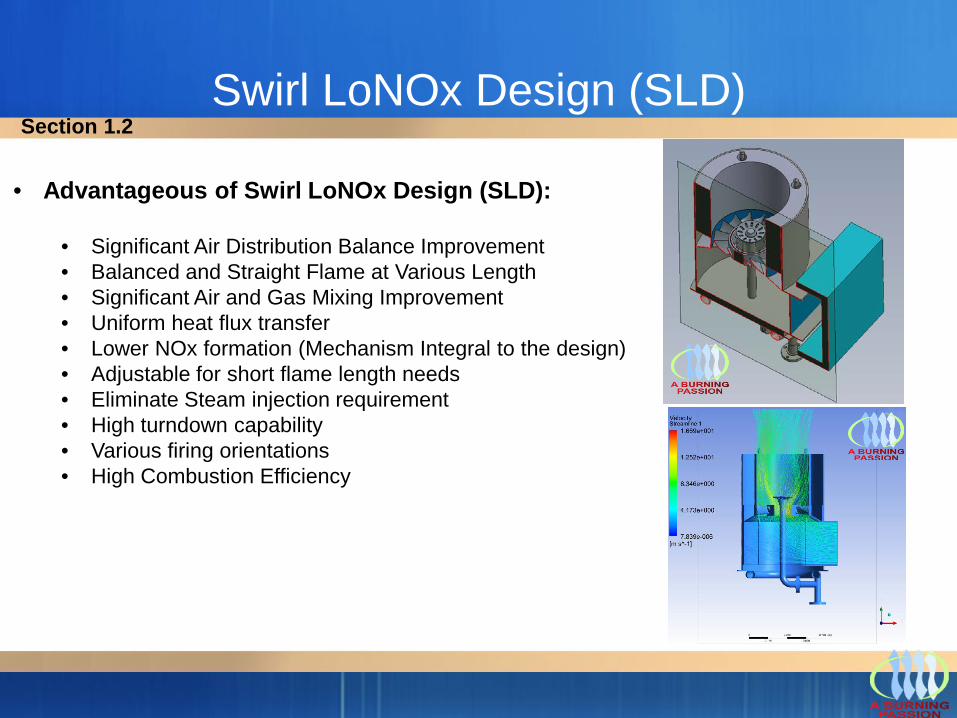
Swirl LoNOx Design (SLD)
• Advantageous of Swirl LoNOx Design (SLD):
• Significant Air Distribution Balance Improvement • Balanced and Straight Flame at Various Length• Significant Air and Gas Mixing Improvement• Uniform heat flux transfer• Lower NOx formation (Mechanism Integral to the design)• Adjustable for short flame length needs• Eliminate Steam injection requirement• High turndown capability• Various firing orientations• High Combustion Efficiency
Section 1.2
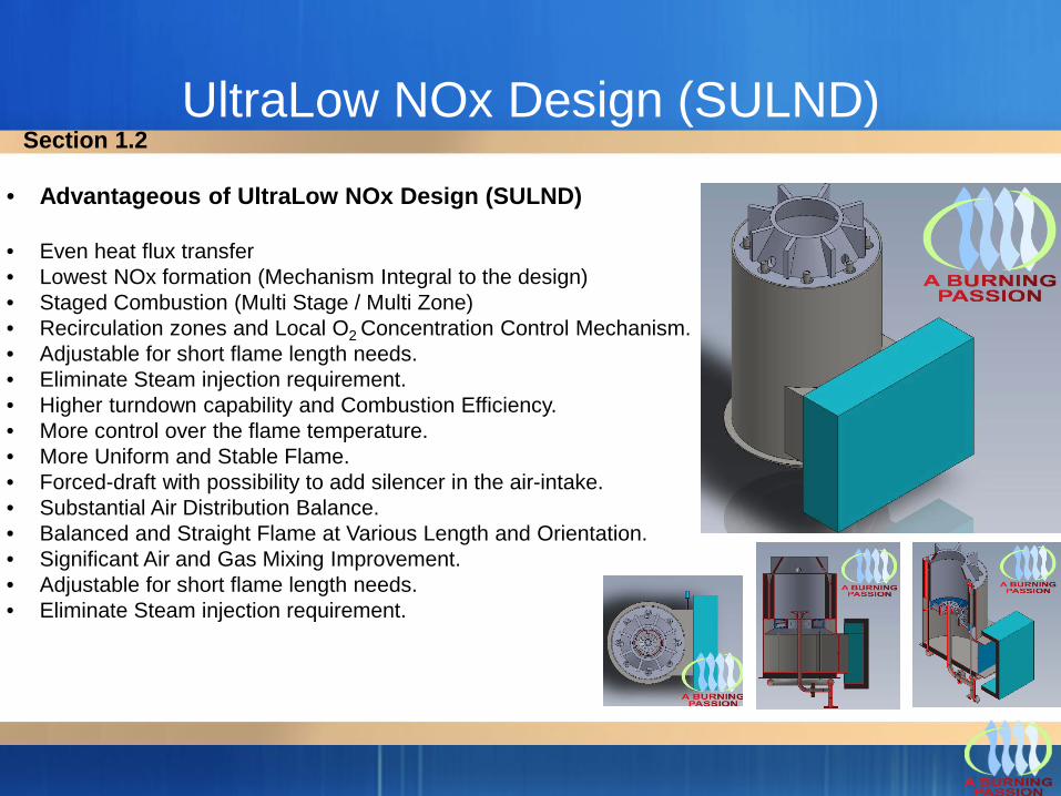
UltraLow NOx Design (SULND)
• Advantageous of UltraLow NOx Design (SULND)
• Even heat flux transfer• Lowest NOx formation (Mechanism Integral to the design)• Staged Combustion (Multi Stage / Multi Zone)• Recirculation zones and Local O2 Concentration Control Mechanism.• Adjustable for short flame length needs.• Eliminate Steam injection requirement.• Higher turndown capability and Combustion Efficiency.• More control over the flame temperature.• More Uniform and Stable Flame.• Forced-draft with possibility to add silencer in the air-intake.• Substantial Air Distribution Balance.• Balanced and Straight Flame at Various Length and Orientation.• Significant Air and Gas Mixing Improvement.• Adjustable for short flame length needs.• Eliminate Steam injection requirement.
Section 1.2
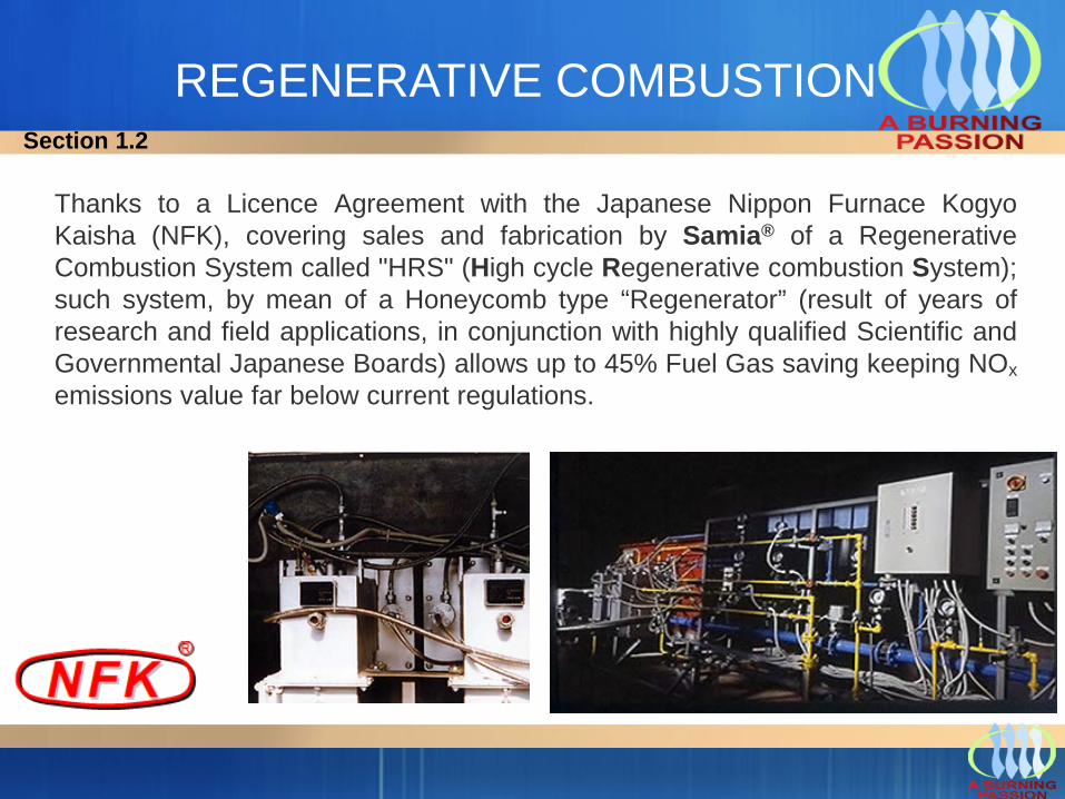
REGENERATIVE COMBUSTION
Thanks to a Licence Agreement with the Japanese Nippon Furnace KogyoKaisha (NFK), covering sales and fabrication by Samia® of a RegenerativeCombustion System called "HRS" (High cycle Regenerative combustion System);such system, by mean of a Honeycomb type “Regenerator” (result of years ofresearch and field applications, in conjunction with highly qualified Scientific andGovernmental Japanese Boards) allows up to 45% Fuel Gas saving keeping NOxemissions value far below current regulations.
Section 1.2
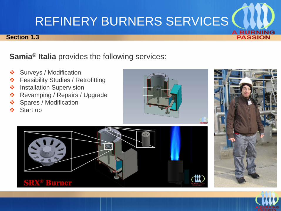
REFINERY BURNERS SERVICES
Samia® Italia provides the following services:
Surveys / Modification Feasibility Studies / Retrofitting Installation Supervision Revamping / Repairs / Upgrade Spares / Modification Start up
Section 1.3
Section 2
FLARESOVERVIEW
Name of Technology: Flare
This includes elevated flares, steam-assisted flares, air-assisted flares, non-assisted flares, sonic flares, enclosed ground flares and Burn Pit Horizontal Flares.
Type of Technology: Destruction by thermal oxidation.
Achievable Emission Limits/Reductions
A properly operated flare can achieve a destruction efficiency of 98 percent or greater when controlling emission streams with heat contents greater than 11 MJ/sm3.
Section 2
Typical Industrial Applications
Flares can be used to control almost any Gas Relief, and can typically handle large fluctuations inconcentration, flow rate, heating value, and inert species content. Flaring is appropriate for continuous, batch,and variable flow vent stream applications, but the primary use is that of a safety device used to control alarge volume of pollutant resulting from upset conditions. Flares find their primary application in thepetroleum and petrochemical industries.The majority of chemical plants and refineries have existing flare systems designed to relieve emergencyprocess upsets that require the release of large volumes of gas.These large diameter flares are designed to handle emergency releases, but can also be used to controlvent streams from various process operations. Gases flared from refineries, petroleum production, andthe chemical industry are composed largely of low molecular weight Gas Relief and have high heating values.Flares used to control waste gases from blast furnaces consist of inert species and carbon monoxide witha low heating value. Gases flared from coke ovens are intermediate in composition to the other twogroups and have a moderate heating value.
Section 2
a. Air Flow: The flow rate through the flare is dependent upon the properties of the waste gas stream andthe configuration of the flare. Steam, air, and pressure-assisted flares add flow to the waste stream in orderto improve flame stability. In cases where the heating value of the waste gas is too low or too high,auxiliary fuel or additional air must be added to the flow, respectively. The maximum flow throughcommercially available flares is about 500 standard cubic meters per second (sm3/sec) and the minimumcan approach zero flow.
b. Temperature: The discharge temperature is typically in the range of 500 to 1100°C (1000 to2000°F), depending upon the composition of the waste gas flow.
c. Pollutant Loading: Depending upon the type of flare configuration (e.g., elevated or ground flares) andthe source of the waste stream, the capacity of flares to treat waste gases can vary up to about 50,000kilograms per hour (kg/hr) of hydrocarbon gases for ground flares and about 1 million kg/hr or more forelevated flares.
Flares are not subject to the safety concern of incinerators having a high concentration of organics in thewaste gas. This is because flaring is an open combustion process and does not have an enclosedcombustion chamber that can create an explosive environment.d. Other Considerations: The waste gas stream must have a heating value of greater than 11 MJ/Sm3(300 Btu/Sf3). If this minimum is not met by the waste gas, auxiliary fuel must be introduced in sufficientquantity to make up the difference.
Emission Stream CharacteristicsSection 2
Emission Stream Pre-treatment Requirements
Liquids that may be in the vent stream gas or that may condense out in the collection header and transfer lines are removed by a knock-out drum. The knock-out is typically either a horizontal or vertical vessel located at or close to the base of the flare. Liquid in the vent stream can extinguish the flame or cause irregular combustion and smoking. In addition, flaring liquids can generate a spray of burning chemicals that could reach ground level and create a safety hazard.
Emission Stream CharacteristicsSection 2
Principle of Operation 1/2
Flaring is a Gas Reliefs combustion control process in which the Gas Reliefs are piped to aremote, usually elevated, location and burned in an open flame in the open air, using aspecially designed burner tip, auxiliary fuel and steam or air to promote mixing for nearlycomplete (> 98%) Gas Relief destruction. Completeness of combustion in a flare is governedby flame temperature, residence time in the combustion zone, turbulent mixing of the gasstream components to complete the oxidation reaction and available oxygen for free radicalformation. Combustion is complete if all Gas Relief are converted to carbon dioxide and water.Incomplete combustion results in some of the Gas Reliefs being unaltered or converted toother organic compounds such as aldehydes or acids.
Section 2
Principle of Operation 2/2
Flares are generally categorized in two ways:
(1) by the height of the flare tip (i.e., ground or elevated),(2) by the method of enhancing mixing at the flare tip (i.e., steam-assisted, air-assisted or non-assisted).
Elevating the flare can prevent potentially dangerous conditions at ground level where the open flame(i.e., an ignition source) is located near a process unit. Elevating the flare also allows the products ofcombustion to be dispersed above working areas to reduce the effects of noise, heat, Smoke, andobjectionable odours.In most flares, combustion occurs by means of a diffusion flame. A diffusion flame is one in which airdiffuses across the boundary of the fuel/combustion product stream toward the centre of the fuel flow,forming the envelope of a combustible gas mixture around a core of fuel gas. This mixture, on ignition,establishes a stable flame zone around the gas core above the burner tip. This inner gas core is heatedby diffusion of hot combustion products from the flame zone.Cracking can occur with the formation of small hot particles of carbon that give the flame its characteristicluminosity. If there is an oxygen deficiency and if the carbon particles are cooled to below their ignitiontemperature, smoking occurs. In large diffusion flames, combustion product vortices can form aroundburning portions of the gas and shut off the supply of oxygen. This localized instability causes flameflickering, which can be accompanied by soot formation. As in all combustion processes, an adequate airsupply and good mixing are required to complete combustion and minimize smoke. The various flaredesigns differ primarily in their accomplishment of mixing.
Section 2
Air-assisted flaresSome flares use forced air to provide the combustion air and the mixing required for smokeless operation. Combustion air is provided by a fan in the bottom of the cylinder. The amount of combustion air can be varied by varying the fan speed.The principal advantage of air-assisted flares is that they can be used where steam is not available.Although air assistance is not usually used on large flares (because it is generally not economical when the gas volume is large) the number of large air-assisted flares being built is increasing.The non-assisted flare consists of a flare tip without any auxiliary provision for enhancing the mixing of air into its flame. Its use is limited to gas streams that have a low heat content and a low carbon/hydrogen ratio that burn readily without producing smoke. These streams require less air for complete combustion, have lower combustion temperatures that minimize cracking reactions, and are more resistant to cracking.
Sonic FlaresSonic flares use the vent stream pressure to promote mixing at the burner tip. Severalvendors now market proprietary, high pressure drop burner tip designs. If sufficient vent stream pressure is available, these flares can be applied to streams previously requiring steam or air assist for smokeless operation. They have multiple burner heads that are staged to operate based on the quantity of gas being released. The size, design, number, and group arrangement of the burner heads depend on the vent gas characteristics.
Steam-assisted flaresSteam-assisted flares are single burner tips, elevated above ground level for safety reasons, that burn the vented gas in a diffusion flame. They reportedly account for the majority of the flares installed and are the predominant flare type found in refineries and chemical plants. To ensure an adequate air supply and good mixing, this type of flare system injects steam into the combustion zone to promote turbulence for mixing and to induce air into the flame.
Section 2
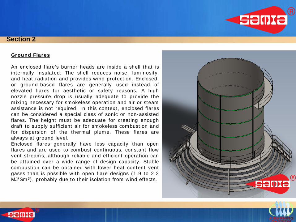
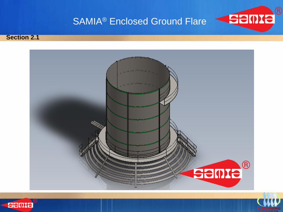
Ground Flares
An enclosed flare's burner heads are inside a shell that isinternally insulated. The shell reduces noise, luminosity,and heat radiation and provides wind protection. Enclosed,or ground-based flares are generally used instead ofelevated flares for aesthetic or safety reasons. A highnozzle pressure drop is usually adequate to provide themixing necessary for smokeless operation and air or steamassistance is not required. In this context, enclosed flarescan be considered a special class of sonic or non-assistedflares. The height must be adequate for creating enoughdraft to supply sufficient air for smokeless combustion andfor dispersion of the thermal plume. These flares arealways at ground level.Enclosed flares generally have less capacity than openflares and are used to combust continuous, constant flowvent streams, although reliable and efficient operation canbe attained over a wide range of design capacity. Stablecombustion can be obtained with lower heat content ventgases than is possible with open flare designs (1.9 to 2.2MJ/Sm3), probably due to their isolation from wind effects.
Section 2
Burn Pit Horizontal Flares
Sometimes erroneously called Ground Flares, this horizontal Flare Tips, are commonly used preferably in low manned areas were large amounts of liquids might be carried over through the Flare Tip itself into a pit adequately sized where these will deposit and, once reached combustible temperature, thank to flame heat of horizontal Flares, will be destroyed by combustion.
AdvantagesAdvantages of flares over other types of Gas Reliefs oxidizers.
1. Can be an economical way to dispose of sudden releases of large amounts of gas;2. In many cases do not require auxiliary fuel to support combustion3. Can be used to control intermittent or fluctuating waste streams.
Other ConsiderationsFlaring is considered as a control option and a safety measure when the heating value of the emission stream cannot be recovered because of uncertain or intermittent flow as in process upsets or emergencies.
Section 2
Section 2.1FLARE ASSEMBLIES
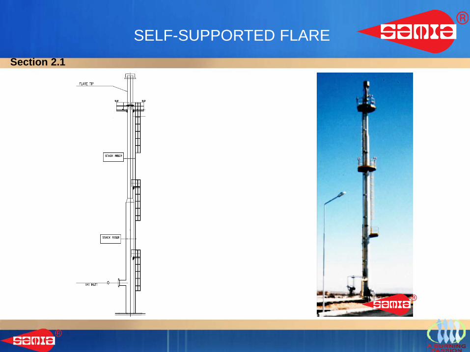
SELF-SUPPORTED FLARESection 2.1
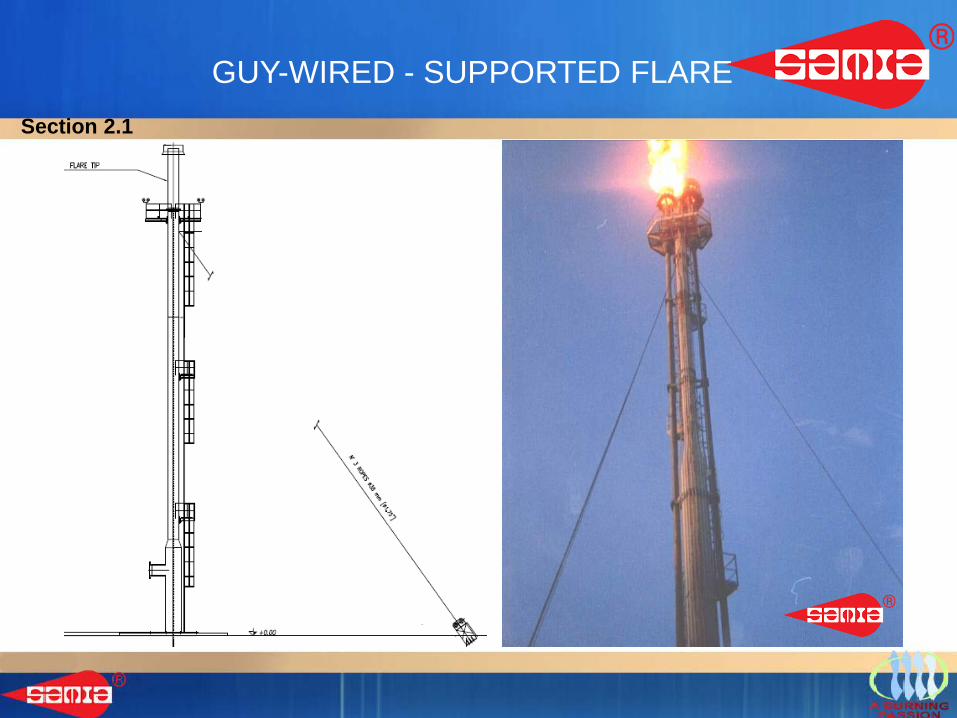
GUY-WIRED - SUPPORTED FLARESection 2.1
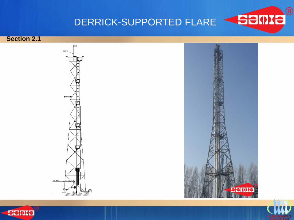
DERRICK-SUPPORTED FLARESection 2.1
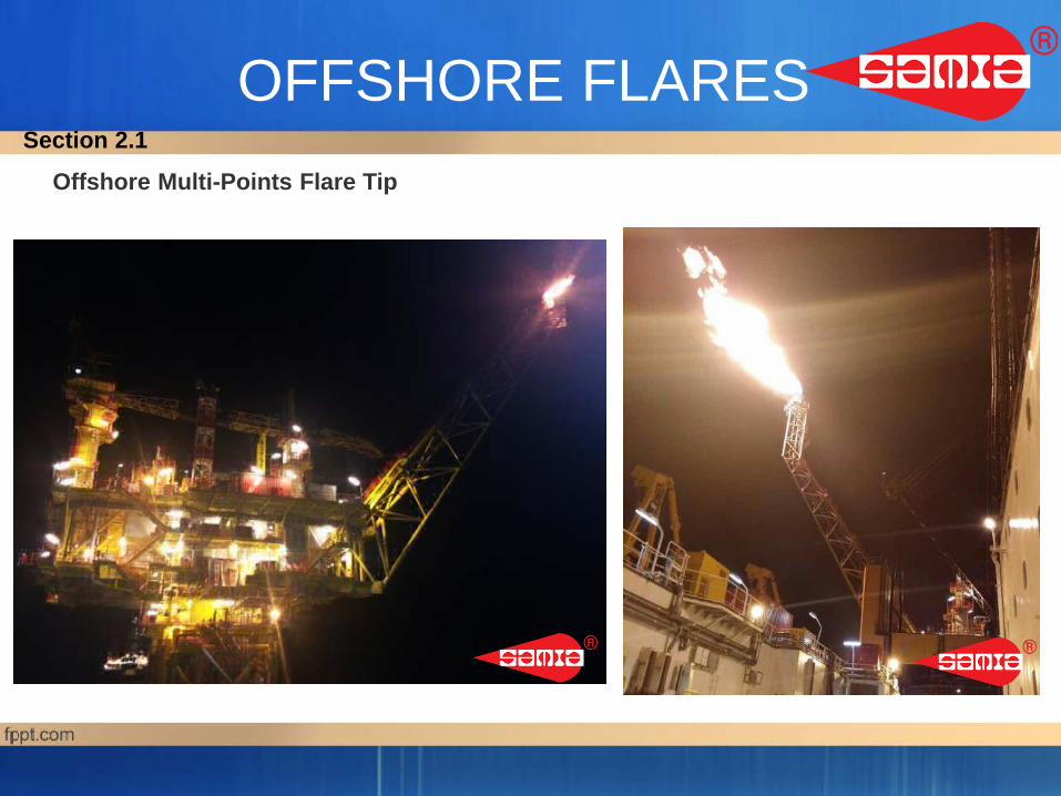
OFFSHORE FLARESOffshore Multi-Points Flare Tip
Section 2.1
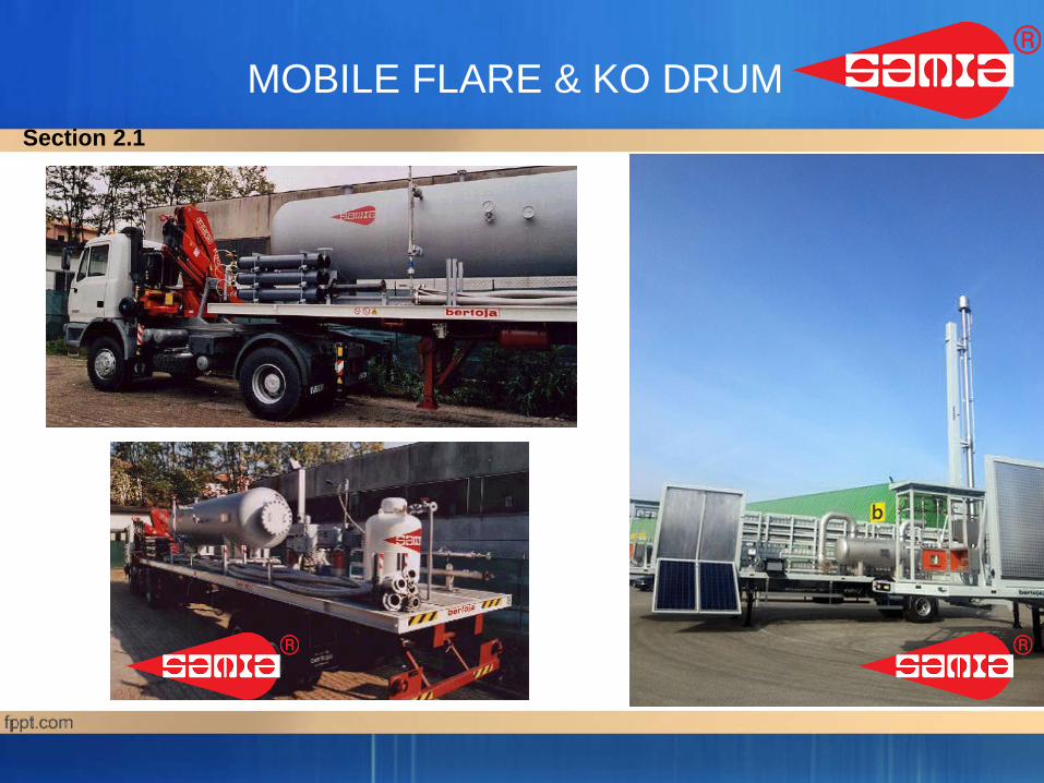
MOBILE FLARE & KO DRUMSection 2.1
SAMIA® Enclosed Ground FlareSection 2.1
Section 2.2FLARE TIPS
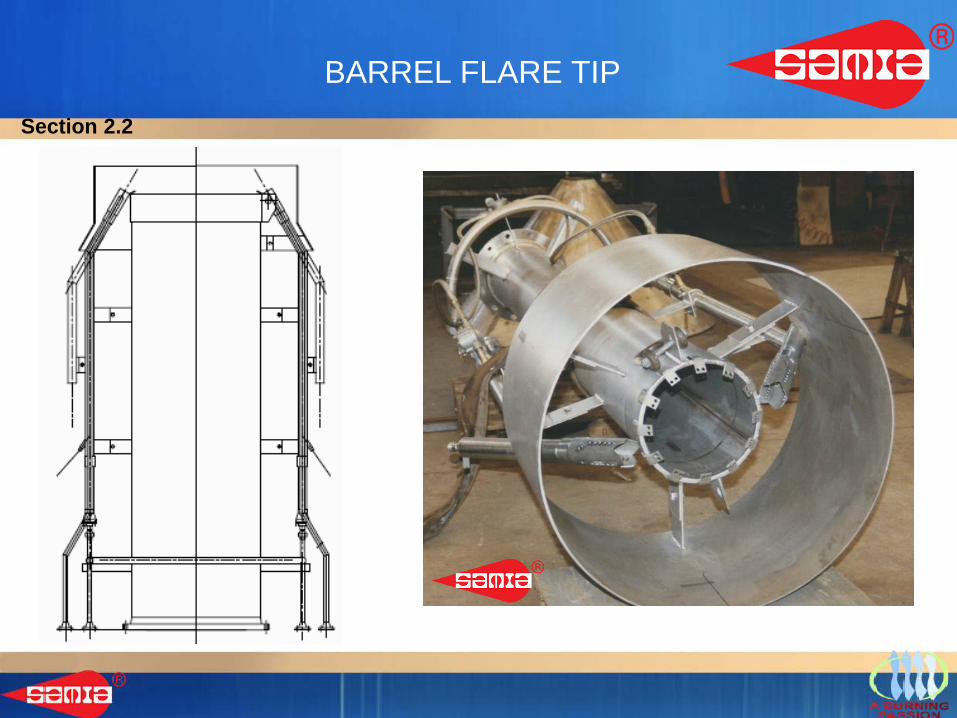
BARREL FLARE TIP Section 2.2
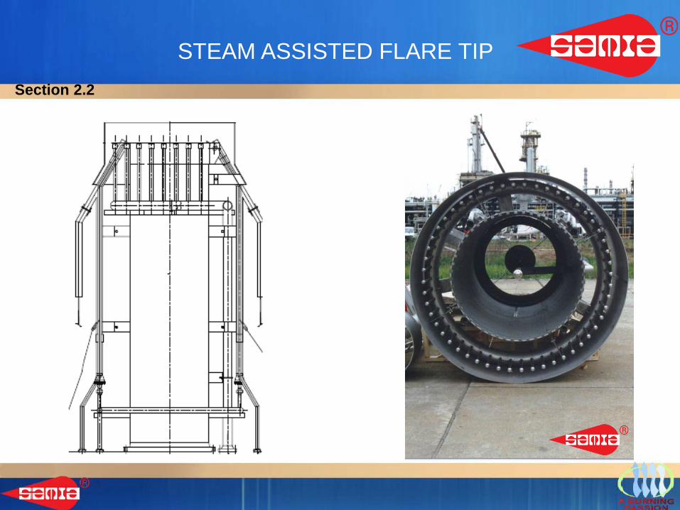
STEAM ASSISTED FLARE TIPSection 2.2
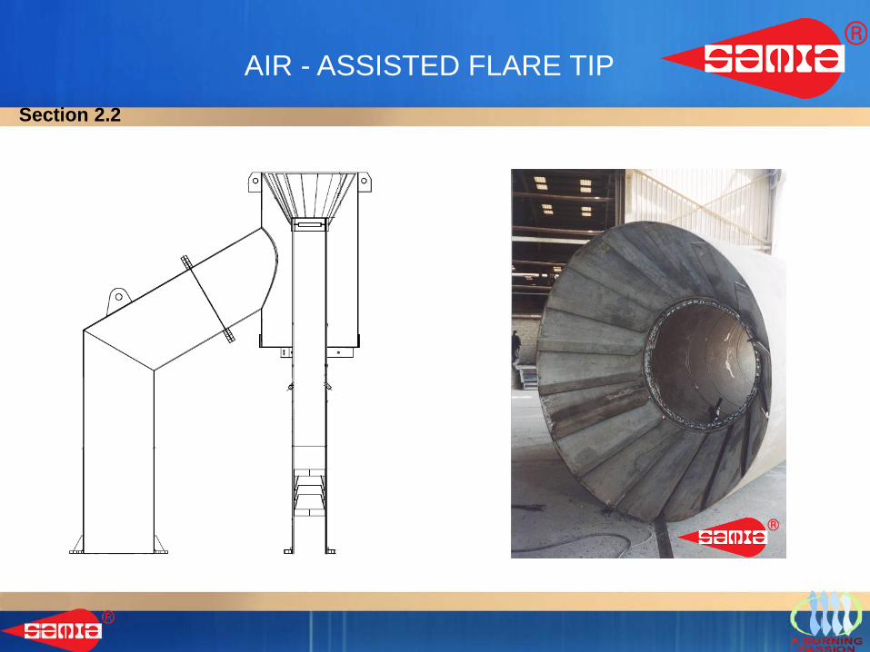
AIR - ASSISTED FLARE TIPSection 2.2
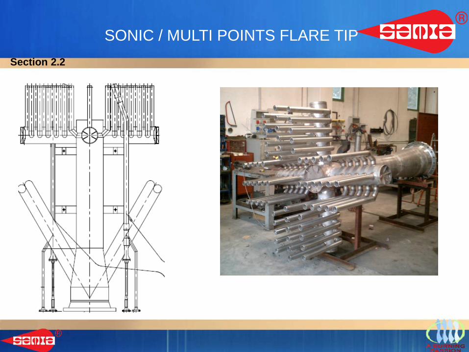
SONIC / MULTI POINTS FLARE TIPSection 2.2
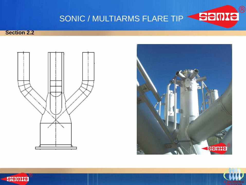
SONIC / MULTIARMS FLARE TIPSection 2.2
Section 2.3FLARE SEALS
SAMIA® DIODE PINECONE
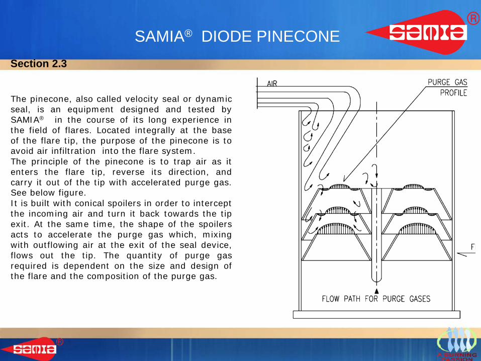
The pinecone, also called velocity seal or dynamicseal, is an equipment designed and tested bySAMIA® in the course of its long experience inthe field of flares. Located integrally at the baseof the flare tip, the purpose of the pinecone is toavoid air infiltration into the flare system.The principle of the pinecone is to trap air as itenters the flare tip, reverse its direction, andcarry it out of the tip with accelerated purge gas.See below figure.It is built with conical spoilers in order to interceptthe incoming air and turn it back towards the tipexit. At the same time, the shape of the spoilersacts to accelerate the purge gas which, mixingwith outflowing air at the exit of the seal device,flows out the tip. The quantity of purge gasrequired is dependent on the size and design ofthe flare and the composition of the purge gas.
Section 2.3
SAMIA® DIODE PINECONE
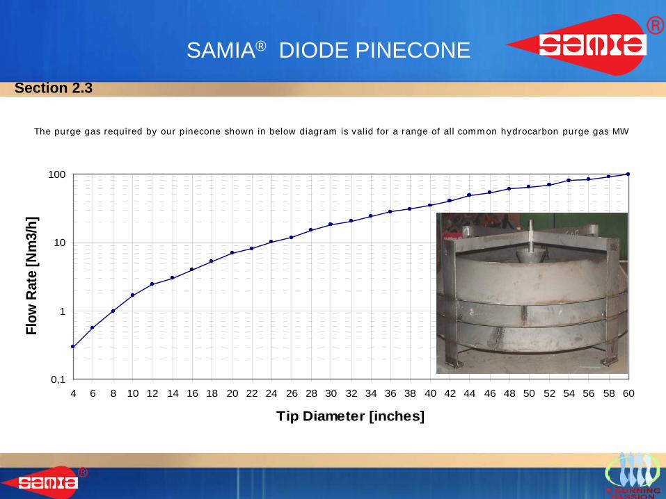
The purge gas required by our pinecone shown in below diagram is valid for a range of all common hydrocarbon purge gas MW
0,1
1
10
100
4 6 8 10 12 14 16 18 20 22 24 26 28 30 32 34 36 38 40 42 44 46 48 50 52 54 56 58 60
Tip Diameter [inches]
Flow
Rat
e [N
m3/
h]
Section 2.3
MOLECULAR SEAL
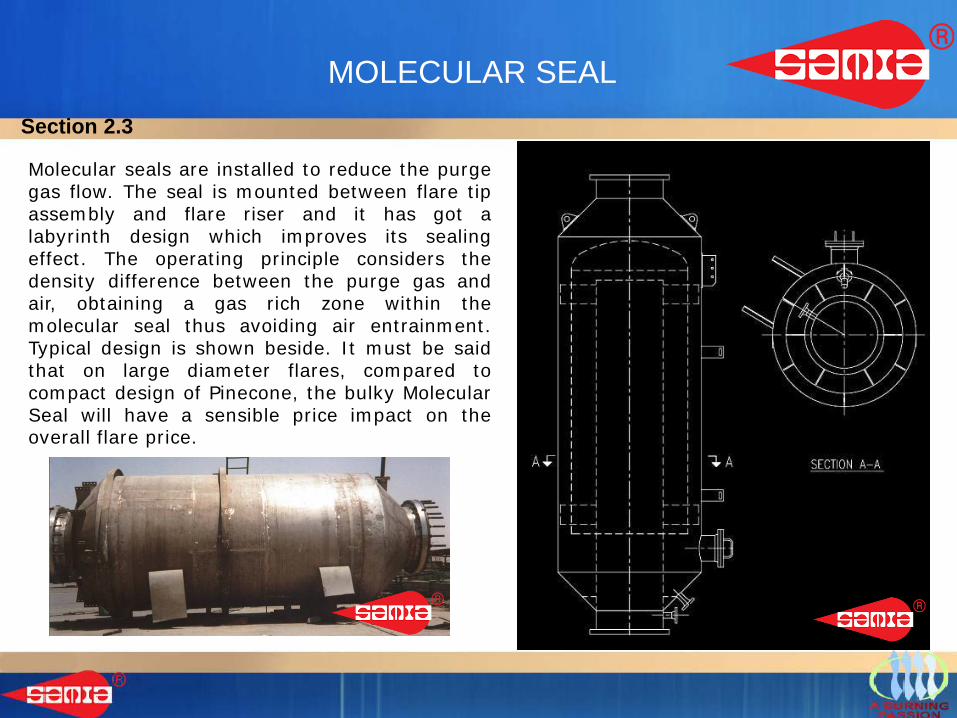
Molecular seals are installed to reduce the purgegas flow. The seal is mounted between flare tipassembly and flare riser and it has got alabyrinth design which improves its sealingeffect. The operating principle considers thedensity difference between the purge gas andair, obtaining a gas rich zone within themolecular seal thus avoiding air entrainment.Typical design is shown beside. It must be saidthat on large diameter flares, compared tocompact design of Pinecone, the bulky MolecularSeal will have a sensible price impact on theoverall flare price.
Section 2.3
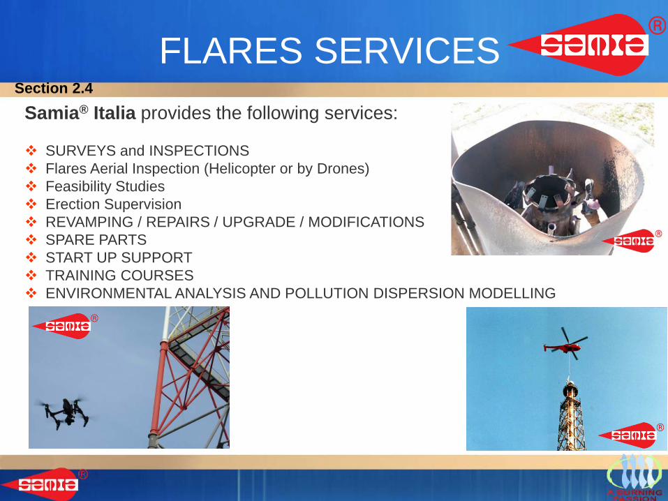
FLARES SERVICESSamia® Italia provides the following services:
SURVEYS and INSPECTIONS Flares Aerial Inspection (Helicopter or by Drones) Feasibility Studies Erection Supervision REVAMPING / REPAIRS / UPGRADE / MODIFICATIONS SPARE PARTS START UP SUPPORT TRAINING COURSES ENVIRONMENTAL ANALYSIS AND POLLUTION DISPERSION MODELLING
Section 2.4
Section 3
Accesories
- SAMIA ITALIA, design and offer accessories and auxiliary equipment for Flare System and Burners including:
• Valves, Hoses, Pilots, Ignition Systems, Fittings, Flanges• Air-Blowers, CO2 System, Nitrogen System and LPG System.• Storage Tanks • Vessels (K.O. Drums and Water Seals (Liquid Seal), Pressure Vessels)• Seals and Prefabricated Piping.• Monitoring System (UV and IR system or combined system)
Section 3
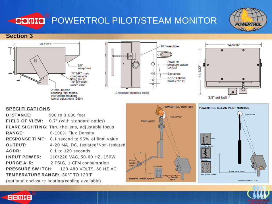
POWERTROL PILOT/STEAM MONITOR
SPECIFICATIONSDISTANCE: 500 to 3,000 feetFIELD OF VIEW: 0.7° (with standard optics)FLARE SIGHTING: Thru the lens, adjustable focusRANGE: 0-100% Flux DensityRESPONSE TIME: 0.1 second to 95% of final valueOUTPUT: 4-20 MA. DC. Isolated/Non-IsolatedAODR: 0.1 to 120 secondsINPUT POWER: 110/220 VAC, 50-60 HZ, 150WPURGE AIR: 2 PSIG, 1 CFM consumptionPRESSURE SWITCH: 120-480 VOLTS, 60 HZ AC.TEMPERATURE RANGE: -30°F TO 120°F(optional enclosure heating/cooling available)
Section 3
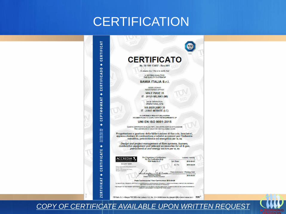
CERTIFICATION
COPY OF CERTIFICATE AVAILABLE UPON WRITTEN REQUEST
Samia® Italia Srl