SALT LAKE CITY SMALL CELL INFRASTRUCTURE DESIGN STANDARDS · • Design Standards or Standards...
40
VERSION SEPT 7, 2018 SALT LAKE CITY SMALL CELL INFRASTRUCTURE DESIGN STANDARDS VERSION SEPT 1, 2018
Transcript of SALT LAKE CITY SMALL CELL INFRASTRUCTURE DESIGN STANDARDS · • Design Standards or Standards...

1VERSION SEPT 7, 2018
SALT LAKE CITY SMALL CELL INFRASTRUCTURE
DESIGN STANDARDS
VERSION SEPT 1, 2018

2VERSION SEPT 7, 2018
SALT LAKE CITY ENGINEERING A Division of Community and Neighborhoods 349 South 200 East, Suite 600Salt lake City, UT 84111 SLC.GOV/engineering

3VERSION SEPT 7, 2018
SALT LAKE CITY SMALL CELL INFRASTRUCTURE
DESIGN STANDARDS

4VERSION SEPT 7, 2018
TABLE OF CONTENTS 1. BACKGROUND AND PURPOSE 1.2 Definitions .................................................... 6
2. GENERAL REQUIREMENTS 2.1 Small Cell Equipment ................................... 7 2.1 New and Replacement Metal Poles ............ 9 2.3 Generally Applicable Requirements ............ 10
3. ATTACHMENTS TO THIRD PARTY UTILITY POLES
3.1 Purpose ........................................................ 13 3.2 Standards ..................................................... 13
4. ATTACHMENTS TO TRAFFIC SIGNAL POLES
4.1 Purpose ........................................................ 14 4.2 Standards ..................................................... 14 4.3 Placement Requirements ............................ 16
5. ATTACHMENTS TO STREET LIGHTS 5.1 Purpose ........................................................ 18 5.2 Standards ..................................................... 18
6. INSTALLATION OF MONOPOLES 6.1 Purpose ........................................................ 22 6.2 Standards ..................................................... 22 6.3 Placement Requirements ............................ 25
7. OTHER ATTACHMENTS (Kiosks, etc.)
7.1 Purpose ....................................................... 30 7.2 Standards ..................................................... 30 7.3 Basis of Design ............................................ 31
8. TECHNICAL SPECIFICATIONS ................................................................................ 32

5VERSION SEPT 7, 2018
BACKGROUND AND PURPOSE
Pursuant to Utah Chapter 54.21, effective September 1, 2018, wireless service providers and wireless infrastructure providers are permitted to locate small wireless facilities in the public right-of-way. This network of low-powered micro antennas provide cellular and data coverage to supplement the provider’s macro-cellular network. New small cell installations will improve the providers’ ability to meet current and future consumer cellular and data needs.
These design standards provide design and aesthetic requirements and specifications that all small wireless facilities installed within the ROW must meet prior to installation within Salt Lake City boundaries. Small cells installed within the ROW are bound to these design standards.
Providers shall consider the aesthetics of the existing street lights and other City infrastructure near proposed small cell locations, with special attention given to the details of neighborhoods with unique street light assemblies. Unique assemblies may include mast arms, decorative pole bases, architectural luminaires, mounting heights, pole colors, etc.
THERE ARE SEVERAL DIFFERENT SMALL CELL INSTALLATIONS ARE PERMITTED WITHIN SALT LAKE CITY:
• Attachments to utility poles and utility lines,
• Attachments to traffic signal poles,
• Attachments to streetlights,
• New freestanding installations (monopoles),
• Other attachments including but not limited to street signs, kiosks, etc.
1
6VERSION SEPT 7, 2018
1.2 DEFINITIONS
• City or Salt Lake City means Salt Lake City Corporation.
• Design Standards or Standards means these design standards adopted by the City.
• FCC means the Federal Communications Commission of the United States.
• Monopole means a new freestanding pole installation for the primary purpose of supporting a small cell. May also be used for lighting or signage as required by the City.
• Provider means a wireless service provider or wireless infrastructure provider.
• Small cell means the wireless facilities and equipment as defined in City Code Chapter 14.56.02, or its successor.
• ROW means the public way as defined in City Code Chapter 14.56.02.
• RMP means Rocky Mountain Power or its successor.
• RF means radio frequency.
• Utility Pole means, for purposes of these design standards, a utility pole owned by a third party utility company, such as RMP or CenturyLink.
SALT LAKE CITY // BACKGROUND AND PURPOSE

7VERSION SEPT 7, 2018
GENERAL STANDARDS TABLE2
2.1 SMALL CELL EQUIPMENTEquipment should match the aesthetics of the pole and surrounding poles.
Equipment shall be installed within an existing pole when technologically feasible and always on a new pole.Any equipment installed within a pole may not protrude from the pole except to the extent reasonably necessary to connect to power or a wireline.
The antenna shall be contained in a cantenna and any other equipment shall be contained in an equipment cabinet, unless the visual impact can otherwise be reduced by its location on the pole.
Requirements per RMP.
May not exceed in width the diameter of the pole by more than 3 inches on either side.
If permitted, may not allow the furthest point of the enclosure to extend more than 18 inches from the pole.
All cables shall be in conduits and shall be flush with the pole unless required to be installed inside the pole.
All hardware attachments should be hidden. Welding onto existing equipment is not permitted.
All equipment should be painted to match pole aesthetics. Paint should be powder coated over zinc paint. If a wood pole, the visible attachments and hardware shall be colored gray.
AESTHETICS
INTERNAL INSTALLS
EXTERNAL SHROUDING
ELECTRICAL SERVICE
WIDTH
SIDEARM (OFF-SET)INSTALLS
CONDUITS
HARDWARE ATTACHMENT
COLOR

8VERSION SEPT 7, 2018
Lockable access door sized to install, maintain, and remove all small cell equipment as needed shall meet provider’s requirements. Utility access shall be perRMP requirements.
All cables should be clearly labeled for future identification.
Cantenna must be mounted directly on top of the pole, unless a side arm installation is required by a pole owner. A tapered transition between the upper pole and cantenna is required.
Cantenna should be maximum of 14 inch diameter.
Any on-pole cabinet and ground mounted utility box should be labeled a (1) RF warning sticker, background to match pole color, no larger than 4 x 6 inches. Facing to the street near the elevation of the antennae, (2) 4-inch by 6-inch (maximum) plate with the provider’s name, location identifying information, and 24-hour emergency telephone number, and (3) No advertising, logos or decals.
There shall be no lights on the equipment unless required by federal law.
Must meet and follow existing City ordinances for ground mounted utility boxes and be attached to a concrete foundation.
The lowest point may not be lower than 8 feet from the grade directly below the equipment enclosure.
As required by RMP and in a location that (1) minimizes its interference with other users of the City’s right-of-way including, but not limited to, pedestrians, motorists, and other entities with equipment in the right-of-way, and (2) minimizes its aesthetic impact.
EQUIPMENT CABINET ACCESS DOORS
CABLES
CANTENNAS
STICKERS
LIGHTS
HEIGHT OF EQUIPMENT ON POLE
GROUND MOUNTED EQUIPMENT BOX
POWER METER
SALT LAKE CITY // GENERAL STANDARDS TABLE

9VERSION SEPT 7, 2018
2.2 NEW AND REPLACEMENT METAL POLESRound. Pole should match aesthetics of surrounding street lights. Pole extension on traffic signal pole should match the rest of the pole.
Attachments to the side of a pole must be placed perpendicular to the street away from the vehicular traffic.
A pole and pole extension shall be galvanized in accordance with AASHTO M 111.
A pole and pole extension shall be painted to match existing street light aesthetics, paint shall be powder coated over zinc paint (Pole shall still be galvanized).
Any pole with a collocated small cell shall not exceed 50 feet including the equipment. Pole shall be measured from the top of the foundation to the top of the cantenna.
All structural components of small cell pole, standard, base, equipment cabinet, couplers, anchor bolts, luminaires, cantenna, and other attachments to be used shall be designed for a minimum of 115 MPH wind velocity, in accordance with AASHTO’s Standard Specifications for Structural Supports for Highway Signs, Luminaires, and Traffic Signals, TIA-222 rev G and ASC 710 with IBC 2012 (or latest standard), plus amendment for snow loading and other local conditions. Any pole not meeting these requirements may not be used for a small cell attachment, or must be replaced.
All cables shall be in conduits and shall be flush with the pole unless required to be installed inside the pole.
On each pole, a (1) RF warning sticker, background to match pole color, no larger than 4 x 6 inches. Facing to the street near the elevation of the antennae, (2) 4-inch by 6-inch (maximum) plate with the provider’s name, location identifying information, and 24-hour emergency telephone number , and (3) No advertising, logos or decals.
POLE STYLE
POLE CONNECTION
COLOR
HEIGHT
DESIGN WIND VELOCITY
CONDUITS
STICKERS
SALT LAKE CITY // GENERAL STANDARDS TABLE

10VERSION SEPT 7, 2018
2.3 GENERALLY APPLICABLE REQUIREMENTSAny small cell is collocated on a pole must comply with the following requirements:
• So as not to significantly create a new obstruction to property sight lines.
• At the intersection of property lines, or along secondary property street facing.
• With appropriate clearance from existing utilities.
• Preferably equidistant from adjacent poles.
• In a single family neighborhood, noise limit to be 5dBA above ambient sound, not to exceed 30 dBA as measured at a property line. Other noise regulations may apply. If the facility does not generate noise, include this information in the submittal so information can be shared with neighborhood.
• Providers shall consider the aesthetics of existing street lights and street furniture in the neighborhood of the proposed small cell locations.
• These aesthetic considerations and accommodations are to be included in the application submittal.
• All equipment located within the public ROW shall be located such that it meets ADA requirements and does not obstruct, impede, or hinder usual pedestrian or vehicular travel or interferes with the operation and maintenance of signal lights, signage, street lights, street furniture, fire hydrants, or business district maintenance.
• Minimize impact to the aesthetics of the excising poles.
• New poles should match aesthetics of adjacent poles.
LOCATION PREFERENCES:
• On-strand attached to a utility pole
• Attachments to utility poles
• Attachment to plain wood or metal street lights
• Installation of monopoles
• Attachment to traffic signal poles
• Attachment to enhanced service area street lights
SALT LAKE CITY // GENERAL STANDARDS TABLE

11VERSION SEPT 7, 2018
• Antenna: Inside a cantenna.
• Monopoles: all equipment inside monopole in base cabinet.
• Utility poles and wood poles: All equipment located on poles if allowed by pole owner, and anything not on the pole to be located in a ground mounted utility box. Fiber in conduits flush with pole.
• Traffic signal poles: All equipment in ground mounted utility box. Fiber inside pole in a conduit (if conduit is not available, pole cannot be used).
• New / replacement metal street light poles: all equipment inside pole in round base cabinet.
• Decorative street lights – replace with equipment inside pole Reusable deviations from these standards shall be approved by Salt Lake City prior to installation.
• Enhanced service area street lights – Replace existing street light with matching street light and all equipment inside pole
• Deviations from this guide may be approved if reasonable on a case-by-case basis by Salt Lake City prior to installation.
• The specifications provided in this chapter are for single carrier with single technology installations within the ROW only. Dual carrier, dual technology installations, or small cell locations not in the public ROW may vary from these guidelines with Salt Lake City approval.
• Placed so as not to interfere with normal operation and maintenance of street light or other street appurtenances.
• Radiation certified to be at safe levels by A non-ionizing radiation electromagnetic radiation report (NIER) shall be submitted to the pole owner and retained on file for equipment type and model.
• The NIER report shall be endorsed by Qualified professional. It shall specify minimum approach distances to the general public as well as electrical and communication workers that are not trained for working in an RF environment (uncontrolled) when accessing the pole by climbing or bucket.
• City workers and contractors to have ability to easily shut off radio signals and power while working on pole. (And we have the right to turn off or disconnect for necessary operations).
SALT LAKE CITY // GENERAL STANDARDS TABLE
SMALL CELL EQUIPMENT SHALL BE MOUNTED ON OR HIDDEN INSIDE THE POLE AS FOLLOWS:

12VERSION SEPT 7, 2018
• Attachments to a pole or any new or replacement pole should have a smooth transition between the small cell and the pole and (except for the top of a cantenna) shall not have any flat surface of more than 1.5 inches to prevent creation of a ledge.
• New small cell facility must be encased in a separate conduit than any City electronics
POWER AND GROUND MOUNTED UTILITY BOXES
• Back up batteries must be in a ground mounted utility box, or underground where possible.
• A separate meter and disconnect is required for both the power and the cell signal that can be accessed and operated by street lighting maintenance personnel.
• Must have metered power.
STANDARDS FOR SMALL CELL FACILITIES WITHIN A LOCAL HISTORIC DISTRICT OR ADJACENT TO A LOCAL LANDMARK SITE. In order to maintain the character of a historic district or conservation district, each as contemplated in Chapter 21A of this code, all wireless facilities and new structures in a historic district or a character conservation district must employ screening, concealment, camouflage, or other stealth techniques to minimize visual impacts. The placement of small wireless facilities on existing structures or new poles shall be subject to the following:
• Installation of small cell facilities within a local historic district or adjacent to a local landmark site shall require a Certificate of Appropriateness subject to the procedures and standards found in 21A.34.020. Such an installation may be considered for an administrative approval as a minor alteration.
• New and replacement structures must be of monopole design; lattice structures and wooden structures will not be permitted.
• Small cell facilities shall not be installed on existing or new poles located in front of a building designated as a local landmark.
• The design of wireless facilities and related new structures must be integrated with existing buildings, structures and landscaping, including considerations of height, color, style, placement, design and shape. Also see Technical Specifications in Section 8.
SALT LAKE CITY // GENERAL STANDARDS TABLE

13VERSION SEPT 7, 2018
3.1 PURPOSE
ATTACHMENTS TO THIRD PARTY UTILITY POLES3
This chapter of the standards for attachment of a small cell facility to a third party pole. A small cell attachment will conform to pole owner’s attachment standards.
Any attachment to a utility pole or utility line must first be approved by the owner of the utility pole. This includes attachment of overhead fiber and on-strand attachments proposed to attach to a utility pole. These standards apply whether attachment is to an existing utility pole, or if the owner requires installation of a replacement pole. A new utility pole installed for the purpose of attaching a small cell is not permitted but would be treated as a monopole.
3.2 STANDARDS

14VERSION SEPT 7, 2018
This chapter of the standards governs attachment of a small cell to the top of an unused traffic signal upright pole. A small cell may not be placed on a traffic signal upright pole where there is a luminaire attached.
4.1 PURPOSE
All provider equipment other than the antenna shall be housed inside a ground mounted utility box or hidden within the cantenna. The antenna may only be attached to the top of the upright pole. No provider equipment shall be strapped to the outside of the signal pole or on a side arm extension.
No physical, electrical, or radio interference by the small cell with the traffic signal:
The provider needs to provide analysis that the proposed small cell shall not cause any interference with City public safety radio system, traffic signal, emergency signal control devices, radio read water meters, “smart” street lights, future “smart city” applications, other city communications components, or any other unforeseen interferences.
4.2 STANDARDS
ATTACHMENTS TO TRAFFIC SIGNAL POLES4

15VERSION SEPT 7, 2018
Figure 4-1: Small Cell Assembly on a Traffic Signal
SALT LAKE CITY // ATTACHMENTS TO TRAFFIC SIGNAL POLES
Traffic Signal Upright Pole
Ground Mounted Utility Box
Signal Pull Box nearest Pole
Spare Street Lighting Conduit
2” Conduit
16VERSION SEPT 7, 2018
• Located on existing traffic signal upright pole
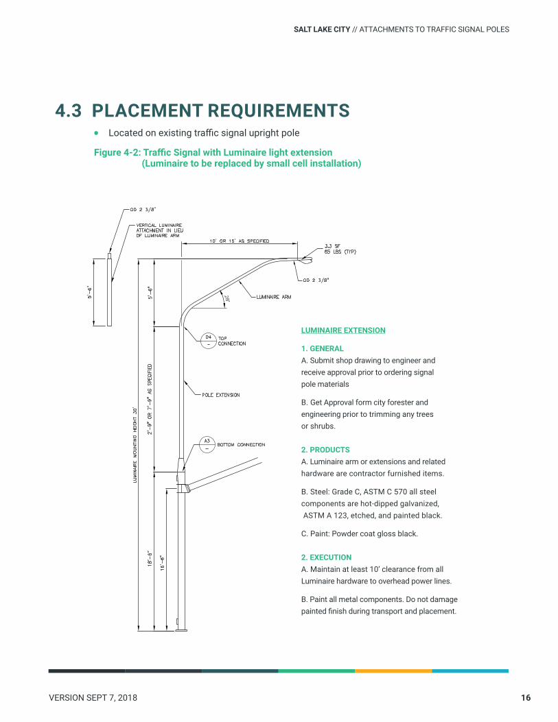
Figure 4-2: Traffic Signal with Luminaire light extension (Luminaire to be replaced by small cell installation)
4.3 PLACEMENT REQUIREMENTS
LUMINAIRE EXTENSION
1. GENERALA. Submit shop drawing to engineer and receive approval prior to ordering signal pole materials
B. Get Approval form city forester and engineering prior to trimming any trees or shrubs.
2. PRODUCTSA. Luminaire arm or extensions and related hardware are contractor furnished items.
B. Steel: Grade C, ASTM C 570 all steel components are hot-dipped galvanized, ASTM A 123, etched, and painted black.
C. Paint: Powder coat gloss black.
2. EXECUTIONA. Maintain at least 10’ clearance from all Luminaire hardware to overhead power lines.
B. Paint all metal components. Do not damage painted finish during transport and placement.
SALT LAKE CITY // ATTACHMENTS TO TRAFFIC SIGNAL POLES

17VERSION SEPT 7, 2018
SALT LAKE CITY // ATTACHMENTS TO TRAFFIC SIGNAL POLES
D

18VERSION SEPT 7, 2018
5.1 PURPOSE
ATTACHMENTS TO STREET LIGHTS5
This chapter governs small cell attachments to a street light. Three different types of small cell installations are permitted on street lights, including:
• Collocating small cell equipment on plain (non-decorative) wood or metal street light poles.
• Replacing an existing or adding a new wood or metal street light pole so that small cell equipment can be attached.
• Collocating on enhanced service area street light poles.
All provider equipment shall be housed internal to the equipment cabinet or hidden behind the cantenna. No provider equipment shall be strapped to the outside of the pole.
On an existing pole, the equipment excluding the antenna shall be shrouded in an equipment cabinet if on the pole, otherwise shielded from view (for example, behind a sign), hidden within the cantenna, or contained in a ground mounted utility box.
On a new street light, the provider may house the equipment inside the pole structure in an equipment cabinet at the base of the upper pole.
5.2 STANDARDS

19VERSION SEPT 7, 2018
A base equipment shall be round with a preferred diameter of a base cabinet 16- inch with a maximum 20- inch diameter.
The meter shall be contained in a ground mounted utility box, unless permitted to be inside an equipment cabinet as approved by RMP.
New street lights or replacement street lights shall comply with the City Street Lighting Master Plan, which provides guidance on luminaire design aesthetics, lighting level criteria, typical street light spacing, and street light details.
• All equipment height shall be above the ground at least 8 feet. If the small cell equipment orients toward the street, the attachment shall be installed no less than 16 feet above the ground.
• Equipment should be oriented away from the street.
• The size of small cells should be minimized as possible to minimize visual impact without interfering with the small cell operation.
• Equipment may not block visibility of street light banners.
An example of an unacceptable small cell installation, and acceptable installation can be found in Figures 5-1 and 5-2.
SALT LAKE CITY // ATTACHMENTS TO STREET LIGHTS
Conduit, mounting bracket, and other hardware must be hidden from view
Cantenna must include a smooth transition between upper pole and cantenna attachment
Upper pole shall be smooth and straight, with 1.5- inch (max.) of flat surface where mounted to the equipment cabinet
Equipment cabinet must be round. 16- inch diameter is preferred, 20-inch diameter max.
Figure 5-1: Unacceptable Figure 5-2: Acceptable

20VERSION SEPT 7, 2018
• Attachments to an enhanced service area light pole cannot change overall character of light or proportion of the luminaires with the placement of a cantenna. The lighting level of service cannot be decreased.
• All new luminaires shall be the same height as adjacent street lights.
• City may require a new street light in lieu of a monopole.
• Wood poles only allowed by approval in areas that are predominately wood or when replacing an existing wood pole.
SALT LAKE CITY // ATTACHMENTS TO STREET LIGHTS
Figure 5-3: Attachment to Wooden Street Light Pole

21VERSION SEPT 7, 2018
Figure 5-4: Combination Street Light Pole with Cantenna and Equipment Shroud
SALT LAKE CITY // ATTACHMENTS TO STREET LIGHTS

22VERSION SEPT 7, 2018
6.1 PURPOSE
INSTALLATION OF MONOPOLES6
This chapter of the Standards is to be used when installing a freestanding small cell installation, referred to as a monopole..
All small cell carrier equipment excluding the antenna shall be housed internal to an equipment cabinet at the base of the pole or hidden behind the cantenna. No provider equipment shall be strapped to the outside of the monopole.
• Monopoles to coordinate with neighborhood pole style and material type.
• New monopoles must be metal (aluminum or steel).
• Ownership of monopoles is to remain with the provider. City reserves the right to attach any sign (such as a no parking sign) on the monopole.
• At least 15% of the pole design structural capacity shall be reserved for future City installations.
• All new poles must have appropriate clearance from existing utilities.
6.2 STANDARDS

23VERSION SEPT 7, 2018
Figure 6-1: Unacceptable MonopoleInstallation
Figure 6-2: Acceptable MonopoleInstallation
SALT LAKE CITY // INSTALLATION OF MONOPOLES

24VERSION SEPT 7, 2018
Figure 6-3: Monopole
Freestanding small cell pole components include the foundation, equipment cabinet, upper pole, cantenna, and all hardware and electrical equipment necessary for a complete assembly, as shown in Figure 6-3
SALT LAKE CITY // INSTALLATION OF MONOPOLES

25VERSION SEPT 7, 2018
All monopoles shall be privately owned and must be permitted by Salt Lake City engineering via the ROW Permit Requirements as outlined in the Master License Agreement.
• Preferred location for new pole is generally on property line to avoid interference with building face, views, business signage, pedestrian flow, etc.
• In a manner that does not impede, obstruct, or hinder pedestrian or vehicular travel.
• So as not to be located along the frontage of a Historic building, deemed historic on a federal, state, or local level.
• So as not to significantly create a new obstruction to property sight lines.
• At the intersection of property lines, or along secondary property street facing.
• Within the street amenity zone whenever possible.
• In alignment with existing trees, utility poles, and street lights.
• Equal distance between trees and other poles when possible, with a minimum of 15 feet separation such that no proposed disturbance shall occur within the critical root zone of any tree.
• With appropriate clearance from existing utilities.
• Outside of the 20-foot equipment clear zone (for base cabinets less than 18-inches in diameter) or 30-foot clear sight triangle (for base cabinets equal to or greater than18-inches in diameter) at intersection corners as shown in Figure 6-7.
• 10 feet away from the triangle extension of an alley way flare.
• Shall not be located within 100 feet of the apron of a fire station or other adjacent emergency service facility.
6.3 PLACEMENT REQUIREMENTS
SALT LAKE CITY // INSTALLATION OF MONOPOLES

26VERSION SEPT 7, 2018
Figure 6-4: Freestanding Small Cell spacing radius
Existing street lights and utility pole locations do not affect into placement requirements
Freestanding poles shall be located a minimum of 250 feet from other freestanding poles
Deployments are exempt from the 250-foot spacing requirement
Figure 6-4 shows freestanding small cells which is preferred to be a minimum of 250 feet apart radially. This radius extends around corners and into alleys. They shall be located in line with trees, existing street lights, utility poles, and other furniture located in the amenity zone, as shown in Figure 6-5.
SALT LAKE CITY // INSTALLATION OF MONOPOLES
STANDARDS FOR MONOPOLES RESIDENTIAL STREETS LESS THAN 60 FEET WIDE:
Residential zones: A wireless provider may not install a new utility pole in a public way adjacent to a residential zone, if the curb to curb measurement of the street is 60 feet wide or less as depicted on the official plat records or other measurement provided with the application, unless the City has given prior written consent based on evidence provided that demonstrates:
• There is insufficient wireless service to meet the demand in the immediate vicinity.
• There are no other feasible options to provide adequate service along the residential street.
• Preferred to be between curb and sidewalk in park strip. If no park strip is available, consider a corner installation before an installation on lawn.

VERSION SEPT 7, 2018 27
Figure 6-5: Freestanding small cell in amenity zone
Freestanding small cells shall be located such that they in no way impede, obstruct, or hinder the usual pedestrian or vehicular travel, affect public safety, obstruct the legal access to or use of the public ROW, violate applicable law, violate or conflict with public ROW design standards, specifications, or design district requirements, violate the Federal Americans with Disabilities Act of 1990, or in any way create a risk to public health, safety, or welfare.
Free standing small cells shall be located within the ROW and off set from the sidewalk as shown in Figure 6-6.
Do not locate small cell in clear sight triangle
SALT LAKE CITY // INSTALLATION OF MONOPOLES

28VERSION SEPT 7, 2018
Freestanding small cells shall be located at intersecting property lines as much as possible. Whenever possible, the freestanding small cell shall be located on the secondary street. Small cells shall also be located a minimum of 15 feet away from trees to prevent disturbance within the critical root zone of any tree, as shown in Figure 6-7.
Figure 6-7: Freestanding small cell location between property and trees
Figure 6-8: Freestanding Small Cell between property lines
Do not locate small cell in the perpendicular extension of the primary street-facing wall plane
Do not locate small cell in front of driveways, entrances, or walkways
The small cells shall not be installed between the perpendicular extension of the primary street-facing wall plane of any single or two-family residence as shown in Figure 6-8.
SALT LAKE CITY // INSTALLATION OF MONOPOLES

29VERSION SEPT 7, 2018
Figure 5-9: Small Cell in Commercial Area
When located adjacent to a commercial establishment, such as a shop or restaurant, care should be taken to locate the small cell such that it does not negatively impact the business. Small cells shall not be located in-front of store front windows, primary walkways, primary entrances or exits, or in such a way that it would impede a delivery to the building. Small cells should be located between properties as much as possible as shown in Figure 5-9.
SALT LAKE CITY // INSTALLATION OF MONOPOLES

30VERSION SEPT 7, 2018
This chapter of the Standards is to be used for small cell installations on other City owned assets located in the public way such as kiosks and signs.
All small cell facilities proposed to be installed on kiosks or signs within the public way shall be approved by Salt Lake City prior to installation.
Salt Lake City owns a small number of kiosks located with the public way. The Kiosks are generally small structures used for advertising local events. Installation of small cell facilities on a kiosk will require all equipment to be installed within the kiosk or the roof structure with a cantenna extending above the roof. The design of the facility must take into account the architectural design of the kiosk and the surrounding development to accomplish the goal of integrating the facility and limiting its visual impact.
Utah Code Chapter 54.21 allows the installation of small cell facilities on signs located within the public way. Most signs in the public way are related to public safety, traffic and parking regulation and provide directional information. Salt Lake City will consider the placement of small cell facilities on pole signs located within the public way only when it can be demonstrated that the small cell facility will not create any hazard for pedestrians cyclists or motor vehicles, visibility of adjacent buildings is not unduly impaired and that the existing structure can adequately handle the structural requirements for such a facility.
7.1 PURPOSE
7.2 STANDARDS
OTHER ATTACHMENTS (KIOSK, ETC.)7

31VERSION SEPT 7, 2018
The small cell facility design and installation shall be compatible with the aesthetics of existing kiosks or signs. The provider shall perform a visual prior to submitting a permitting application to determine existing aesthetics. The small cell components shall be sized to be proportional and limit the potential impact along the streetscape.
DESIGN STANDARDS FOR KIOSKS
• All hardware connections shall be hidden from view.
• Equipment installed on kiosks should be shrouded under the kiosk cap or roof.
• The cantenna may extend a maximum of 5 feet above the kiosk cap or roof.
• The cantenna assembly will be circular with cabling shrouded or enclosed.
• The cantenna shall match the color of the kiosk or utilize another color that best minimizes the visibility of the antenna.
• The small cell facility must meet all appropriate structural standards and wind loading specifications.
• The small cell facility shall be architecturally compatible with the design of the kiosk and create a cohesive aesthetic.
DESIGN STANDARDS FOR SIGNS
• Small cell facilities attached to freestanding Salt Lake City owned pole signs in the public way shall only be allowed on existing signs poles.
• The small cell antenna shall only be installed on top of the sign pole.
• The small cell antenna shall extend a maximum of 5 feet above the height of the existing sign pole and shall be installed above the sign mounted on the pole.
7.3 BASIS OF DESIGN
SALT LAKE CITY //OTHER ATTACHMENTS (KIOSK, ETC.)

32VERSION SEPT 7, 2018
The following sections describe in detail the foundation and electrical specifications. All work completed in the ROW must be in accordance with Salt Lake City Design Standards.
This work consists of furnishing and installing foundations, small cell poles, conduit, junction boxes, cable, wiring, junction boxes, and incidental materials for small cell installation in accordance with these specifications and in conformance with the details, lines, grades, and locations shown on the plans.
MATERIALS
Small Cell facilities’ materials shall conform to Small Cell and Electrical Materials.
A) FOUNDATIONS. Concrete bases and equipment pads shall be pre-cast or cast-in-place concrete per the City standard to meet ACI 318. A complete foundation includes the concrete, reinforcing steel, anchor bolts, leveling nuts, conduit stubs, ground rod and wire, excavation and backfill, restoration, accessories as required to provide a complete unit. Banner arm (if required) wind loading shall be incorporated into light standard structural design.
B) SMALL CELL STANDARD. A complete light standard includes the metal upper pole, mounting bracket, mast arm(s), cantenna, equipment cabinet, base, grounding system, and all hardware. The upper pole shall have a handhole at the top to maintain City fiber and street light electrical service. An optional handhole shall be provided at the bottom of the upper pole if fiber and electrical service cannot be accessed from the equipment cabinet.
Pole and mast arm or arms shall be the type and size shown on the plans.
C) CONDUIT. Conduit includes conduit, trenching, backfill, jacking, augering, fittings, drainage tees, sealing, restoration, and accessories as required to provide a complete installation.
D) ELECTRICAL WARNING TAPE. Detectable electrical warning tape shall consist of pre-manufactured non- adhesive polyethylene material that is unaffected by acids, alkalines, and other soil components. The color of the tape shall be red, and it shall be, at a minimum, 3.5 mils thick and 6 inches wide. Its tensile strength shall be 2,500 psi lengthwise.
The electrical tape shall include the following identification printed in black letters continuously along the length of the tape: “CAUTION BURIED ELECTRIC LINE BELOW”.
The identification note and color of tape shall conform to the requirements of the “American Public Works Association (APWA) Uniform Color Codes (Red) – Electrical Power Lines, Cables, Conduit and Lighting Cables.”
E) CONDUCTORS. Conductor includes control wiring, luminaire wiring, main circuit wiring, ground wiring, service entrance wiring, pulling, splicing, connections, testing, and all other wiring necessary for a complete installation.
TECHNICAL SPECIFICATIONS8

33VERSION SEPT 7, 2018
F) PULL BOXES. Pull box includes pull box, cover with bolts, excavation, gravel base, backfill, sealing, restoration, and accessories as required to provide a complete installation.
G) MATERIALS LIST. At the preconstruction conference the Contractor shall submit to Salt Lake City three copies of a list of all materials and equipment to be incorporated into the work. The Contractor shall include the following items on the list:
• Small cell standards
• Pull Box
• Fuse holders
• Conductors
• Conduit
• Wireless Lighting Control and Monitoring System
• Small cell foundations
• Equipment pads
• All other items required for a complete installation
Salt Lake City will return lists that are incomplete or that include unacceptable materials to the Contractor for correction and re-submission.
The Contractor shall not order materials or equipment until Salt Lake City and the party or agency responsible for maintenance have reviewed and approved the materials and equipment list. Salt Lake City’ approval of the list shall not relieve the Contractor responsibility for the proper functioning of the completed installation.
GENERAL
All work shall conform to these specifications and the National Electrical Code (NEC) when the small cell pole is owned by Salt Lake City or the provider, or the National Electrical Safety Code (NESC) when the small cell pole is owned by Rocky Mountain Power.
The Contractor and/or provider shall keep fully informed of and comply with all Federal, State, and local laws, ordinances, and regulations, and all orders and decrees of bodies or tribunals having any jurisdiction or authority, which may affect those engaged or employed on the work, or affect the conduct of the work. The Contractor and/or provider shall protect and indemnify Salt Lake City and its representatives against any claim or liability arising from or based on the violation of any such law, ordinance, regulation, order or decree, whether by the Contractor and/or provider, the subcontractors, suppliers of materials or services, or their employees
SALT LAKE CITY // TECHNICAL SPECIFICATIONS

34VERSION SEPT 7, 2018
Each system shall be installed as shown on the plans or as designated. The Contractor and/or provider shall furnish and install all incidentals necessary to provide a complete working unit or system.
CONCRETE FOUNDATION PADS AND SMALL CELL STANDARD FOUNDATIONS.
Foundations shall be installed as shown on the plans, complete with grounding. The Contractor and/or provider shall test and report soil conditions to Salt Lake City as necessary to ensure proper installation of foundations. Foundations shall be installed at the final grade.
All anchor bolts shall be positioned by means of steel templates. The center of the template shall coincide with the center of the foundation. Anchor bolt size and 19.5-inch bolt circle shall accommodate a 16-inch equipment cabinet per manufacturer’s requirements. Anchor bolt size and 23.5-inch bolt circle shall accommodate a 20-inch equipment cabinet per manufacturer’s requirements.
All small cell standard foundations shall be as detailed.
Conduits shall be properly positioned and anchored before the concrete is placed.
Coordinate the base setback and orientation with Salt Lake City.
All foundations shall have ground rods conforming to the NEC or NESC. All foundations on structures shall be grounded to the structural steel by a method that is in accordance with the NEC or NESC and which is approved by Salt Lake City.
Concrete shall be Class B.
Anchor bolts shall be designed by the Contractor’s and/or provider’s engineer or as shown on the working drawings. The threaded ends of the anchor bolts, the nuts, and the washers shall be galvanized in accordance with ASTM A153.
ALL POLES AND CANTENNA STANDARDS
Metal small cell standards shall be fabricated of steel unless otherwise approved by Salt Lake City. Whenever Small Cell Standard Metal is specified, the Contractor and/or provider shall furnish galvanized steel. The Contractor and/or provider may furnish aluminum small cell standards if Salt Lake City gives approval. Material type and shape of small standards shall be the same throughout the design district, unless otherwise approved by Salt Lake City.
All standards shall have weatherproof cable-entrance grommets located in conformity with the type of mounting used. Metal surfaces shall be free of imperfections marring the appearance and of burrs or sharp edges that might damage the cable.
All metal poles shall be straight and shall be supplied with polecaps when applicable.
Steel mast arms shall be made of Schedule 40 standard steel pipe conforming to ASTM A 53.
SALT LAKE CITY // TECHNICAL SPECIFICATIONS

35VERSION SEPT 7, 2018
All steel poles, mast arms and base flanges shall be hot-dip galvanized in accordance with ASTM A 123. Units on which the spelter coating has been damaged shall be repaired as provided in AASHTO M 36, or other approved method.
Base flanges for steel poles shall have continuous welds both inside and outside, unless otherwise permitted. Base flanges inserted into the pole and bonded shall meet the requirements for materials and strength stated herein.
Each metal standard shall be wired with a breakaway fused connector of proper capacity rating. The fused connector shall be located in the equipment cabinet. If the light standard has no equipment cabinet, the fused connector shall be located in the pole at the hand hole.
All equipment cabinets or bases shall have vandal resistant, removable access doors.
Hardware used with steel standards shall be either cadmium plated steel, hot dip galvanized steel, or stainless steel.
Materials shall be of a standard line from a name brand manufacturer or as specified in this document. Electrical material shall be listed by the Underwriters’ Laboratories, Inc. (UL), and shall conform to the National Electrical Code (NEC) when the street lights are owned by SLC, or the National Electrical Safety Code (NESC) when the street lights are owned by the Utility. Material shall be the same as, or compatible with, that used and accepted by the agency responsible for maintenance.
Salt Lake City may inspect all lighting material and all electrical materials and all other materials and accept or reject them at the project site. Samples may be taken or manufacturer’s certifications may be accepted in lieu of samples.
Poles, equipment cabinets, and bolts shall be galvanized stainless steel. Galvanizing will be performed in accordance with ASTM 123 and meet the following galvanization and paint requirements.
1. Galvanizing will be SSPC-SP1 Solvent wiped where needed and the Galvanizing will receive a sweep blast to a uniform dull appearance. Any areas of fracture will be repaired. Any excess zinc build up should be blended to no higher than the height of a dime with no thick edges or areas that may cause paint entrapment potentially leading to a premature coating failure.
The first epoxy coat typically should be applied within 120-180 minutes of abrasive blasting. Items shall be cleaned free of blast debris before coating. Compressed air should be used to clean items; items should be free of Oil, residue, and any other contaminates/debris.
• Epoxy Primer Gray- B107989EA80K-A
• Impact Resistance Direct 100 IN/LBS @ 2.0-3.0 Mils (ASTM D2794)
• Impact Resistance Indirect- 100 IN/LBS @ 2.0-3.0 Mils (ASTM D2794)
SALT LAKE CITY // TECHNICAL SPECIFICATIONS

36VERSION SEPT 7, 2018
• Cross- Hatch Adhesion 5B (ASTM D3359)
• Conical Mandrel 1/8” (ASTM D522)
• Pencil Hardness 2H (ASTM D3363)
• Specific Gravity 1.58 +/- 0.05 G/ML
• Theoretical Coverage 121.63 ft2/LB @ 1.0 Mil
• 60 percent gloss 75-85 (ASTM D523)
The Epoxy prime coat shall be applied on poles for an DFT Average of 5.0 Mils for the bottom eight feet, 3.0 Mils DFT above that. Arms have the epoxy prime applied for a 3.0 mil DFT. DFT readings shall be taken in accordance with SSPC-PA2.
Top coat to be applied for an DFT of 3.0 mils average unless noted otherwise.Aerosol touch up should used for coverage on areas that were masked by a hanging device (Hanging hook or chain, etc) or used to repair small scratches or imperfections.
Poles shall be set plumb, and centered, on the small cell standard foundation using leveling nuts when installed.
Defects and scratches on painted, powder-coated, or anodized poles shall be primed and painted with a color-matched paint to match undamaged pole sections. Defects and scratches on galvanized poles shall be re-galvanized in the field.
Stainless steel mounting hardware shall be used to mount luminaires, mast arms, access doors, cantenna, equipment cabinet, and other hardware to the poles. Apply an approved zinc-based anti-seize compound to all mounting hardware prior to assembly.
Banner arms (if required) shall be incorporated into small cell standard structural design.
CONDUIT
All conduit shall be installed within the public Right of Way and shall be at least two-inch (2” minimum) inside diameter unless otherwise designated on the plans. The Contractor and/or provider may use larger conduit than specified. If larger conduit is used, it shall be for the entire run from outlet to outlet. Reducer couplings shall not be used. Larger conduits shall be sized to accommodate the constraints established by the hole in the pole anchor base plate.
Conduit terminating in standards or pedestals shall extend approximately two inches past the foundations and shall slope toward the junction box opening. Conduit entering pull boxes shall terminate two inches inside the box wall and two to five inches above the bottom, and shall slope toward the top of the box to facilitate pulling of conductors. Conduit entering through the bottom of a pull box shall be located near the end walls to leave the major portion of the box clear. At all outlets, conduits shall enter from the direction of the run.
The ends of all conduits, whether shop or field cut, shall be reamed to remove burrs
SALT LAKE CITY // TECHNICAL SPECIFICATIONS

37VERSION SEPT 7, 2018
and rough edges. Cuts shall be made square and true so that the ends will butt or come together for their full circumference.
Unless otherwise specified, conduit shall be rigid non-metallic electrical conduit currently recommended and approved by Underwriters’ Laboratories, Inc. for the proposed use conforming to ASTM-F 441 schedule 40, (Schedule 80 or bored HDPE where installed under roadways).
Fittings shall be the type used outside the conduit and PVC cement welded. Submersible fittings shall connect the conduit in a manner that makes the joints watertight.
All in-grade Pull Boxes shall be polymer concrete, bottomless and tier 22 rated bolted covers. 13 inches by 24 inches and 18 inches deep manufactured by Quazite; Cat. # PG1324BA18, unless otherwise noted on the plans. Covers shall be Cat. # PG1324HH00 with stainless steel bolts and the word “ELECTRIC” molded into the top
Non-metallic conduit shall be cut with a hacksaw or other approved tool. Non-metallic conduit connections shall be the solvent-weld type.
Conduit connections at junction boxes shall be tightly secured and waterproofed. All conduit ends shall be sealed with duct seal after installation of wiring. The duct seal shall be rated for outdoor use.
When specified, conduit shall be installed under existing pavement by boring operations. Where plans show that existing pavement is to be removed, jacking the conduit is not required. Jacking or drilling pits shall maintain a minimum of two feet clear of the edge of pavement. Water shall not be used as an aid in the jacking or drilling operations.
Trenching shall be in conformance with Salt Lake City standards. Backfill shall be per Salt Lake City standards. Detectable red electrical warning tape shall be installed between six inches and 12 inches below finished grade for all underground conduit runs.
Underground conduit shall be buried a minimum of two feet below finished grade. There shall be no sag between boxes. Conduit within the public ROW shall be buried 48 inches (maximum) below finished grade.
Junction Boxes shall be placed at conduit ends, at all locations where conduit bends in a single run would equal 360° or greater per NEC requirements, and at all other locations shown on the plans. The Contractor may install additional pull boxes to facilitate the work.
Excavate minimum 24 inches below base depth of each junction box, backfill and compact with pea rock to permit draining of water.
Placement and setback of the junction boxes shall be coordinated with Salt Lake City.
Unless otherwise shown on the plans or directed by Salt Lake City, junction boxes shall
SALT LAKE CITY // TECHNICAL SPECIFICATIONS

38VERSION SEPT 7, 2018
be installed so that the covers are level with the sidewalk grade. Covers shall be flush with the surrounding finished ground when no grade is established.
Where a conduit stub-out is called for on the plans, a sweeping elbow shall be installed in the direction indicated. All conduit stub outs shall be capped. WIRING
All wiring shall be copper, 600 Volt rated, Type: Conform to the applicable UL and ICEA Standards for the use intended. Copper conductors with 600-volt insulation unless otherwise specified or noted on the drawings. Stranded conductors for No. 8 and larger, with the exception of the ground rod conductor shall be #6 AWG solid, bare, copper.
Aluminum Conductors Prohibited: Aluminum conductors will not be permitted. Insulation: Type THWN/ XHHW for underground installation in conduit, insulation minimum unless otherwise specified or noted on the drawings. Size: No. 12 minimum unless otherwise specified or noted on the drawings. Not less than NEC (NESC if Utility owned) requirements for the system to be installed.
Color Coding: Phase, neutral and ground conductors color-coded in accordance with NEC (NESC if Utility owned). Connect all Conductors of the same color to the same phase conductor as follows:
208Y/120V-3PH-4W Color coding shall be:
1) Phase = Black2) Phase = Red3) Phase = Blue4) Neutral = White5) Ground = Green
120/240V-1PH-3W Color coding shall be:
1) Line 1 = Black2) Line 2 = Red3) Neutral = White4) Ground = Green
Unless otherwise authorized, the multiple system of electrical distribution shall be used. Conductors of the size and material specified shall be installed for control wiring, luminaire wiring, small cell equipment wiring, City IOT wiring, main circuit wiring, ground wiring, service entrance wiring, and all other wiring necessary for a complete installation.
Conductors shall be sized to prevent a voltage drop of more than three percent per feeder run. All conductors shall be installed in conduit.All power and lighting circuits shall include an insulated green grounding conductor.
A complete grounding system shall be installed for the entire lighting installation.Grounding shall consist of ground cables, conduits, grounding rods, wire or strap, and ground fittings, as required by the NEC (or NESC if Utility owned).
SALT LAKE CITY // TECHNICAL SPECIFICATIONS

39VERSION SEPT 7, 2018
Type THWN conductors shall be used for all underground conduit runs. Leave sufficient lengths of branch conductors to allow conductor splices to be extracted from pole base for maintenance. Type XHHW shall be used for the service entrance conductors.
Extend three conductor SOW cable feeder leads to the luminaires from the cables in the pole base.
Install in-the-line fuses on each feeder lead. Leave sufficient lengths of feeder conductors to allow fuses and conductors to be extracted from pole base for maintenance.
Provide a No. 6 AWG solid, bare, copper wire connection to ground rod with ample length to allow connection to light standard, and system ground conductor.
Attach grounding conductor to the energy suppliers neutral at the service point. Terminate grounding conductor with less than 25 ohms ground reference at the service point. If ground resistance is greater than 25 ohms, add additional ground rod(s) or other ground reference bond to bring the resistance to under 25 ohms resistance to earth. Provide ground rods elsewhere as shown on the drawings. Butt splices within the bases are not acceptable.
Butt splices within the bases are not acceptable.
At each pole, provisions shall be made for convenient sectionalizing of the circuits. This shall be done by providing ample length (18 to 24 inches) of branch conductor ends and performing splices using submersible type (Burndy Uni-tap connectors or an approved equal). Wire nuts are not an acceptable method for splicing. Splicing shall only be performed within the pole bases and splice boxes where applicable.
Separation of service shall be provided within the pole by conduit or dividers. Electrical wiring and fiber shall be separated by Owner within.
AS-BUILT DRAWINGS
Contractor shall supply accurate as-built drawings of the project to Salt Lake City. Drawings shall indicate location and setback of conduit, lighting control center, and utility service point, and pole locations along the roadway measured from a reliable location.
FUSES
Each luminaire in the 120-volt system shall be fused with one 6-amp fuses. Fuse connectors shall be installed in the phase wires of their respective circuits at the pull box located adjacent to the light standards or in the pole base. The fuses shall be mounted in inline single-pole molded fuse connector/holders. The fuse holders shall be a DOT-PLUG (Catalog No. Duraline-16998), or approved equal.
SALT LAKE CITY // TECHNICAL SPECIFICATIONS

40VERSION SEPT 7, 2018
Fuses shall be of the breakaway type. The Contractor shall provide sufficient excess conductor length to allow withdrawal of the connected fuse holder. The grounding wires shall not be fused. Fuses and fuse holders shall be “UL” listed and shall be installed in such a manner that the fuse stays with the load side when holder is separated. In addition, the Contractor shall form loops in the leads on each side of the fuse holders and so position the fuse holders so that they may be easily removed or inserted through the opening at top of pull box.
SECONDARY SERVICE PEDESTALS
The service cabinet shall include all equipment necessary to connect to the energy provider’s overhead secondary conductors or transformer.
All-In-One commercial meter/power pedestal and non-metered/power pedestals shall meet or exceed Salt Lake City’s Standards.
SALT LAKE CITY // TECHNICAL SPECIFICATIONS