
SAILOR SYSTEM 5000 MF/HF 150W - peel.dk System 5000 MF-HF, 150W (User manual).pdf · ITU...
44
SAILOR SYSTEM 5000 MF/HF 150W USER MANUAL
Transcript of SAILOR SYSTEM 5000 MF/HF 150W - peel.dk System 5000 MF-HF, 150W (User manual).pdf · ITU...

SAILOR SYSTEM 5000 MF/HF 150W
USER MANUAL


IntroductionCongratulations on your new SAILOR CU5110 MF/HF maritime radio telephone with built-inDSC (Digital Selective Calling) system, fulfilling the highest international standards formarine MF/HF communication and safety procedures. The transceiver is born with a2187,5kHz DSC watch receiver forming an ideal system for MF installations. If connected toa GPS or other maritime navigation system it can automatically include the true UTC timeand your position in its DSC distress messages.
This SAILOR marine equipment is a part of the modular system 5000 which also includes aHF single sideband radiotelephone. SAILOR marine equipment is specially designed for theextremely rugged conditions on bord a ship, based on more than 50 years’ experience withall kinds of boats, from small pleasure crafts, over fishing boats working under all climaticconditions, to the biggest ships.
SAILOR ® is one of the worlds leading manufacturers of maritime radiocommunicationequipment - a position which has been maintained by means of constant and extensiveproduct development. We have a worldwide network of dealers with general agencies inmore than 80 countries. All our dealers are specially trained to service all your SAILOR ®products.
About this manualThis manual is for the daily user of the system. Additionally, it includes a section on theinstallation procedures, and - on page iii - standard distress procedures. We highly recom-mend you to read the manual before you start using the equipment.
Notice: There may be some minor differences in the graphic layout of the manual comparedto the physical device.
DisclaimerAny responsibility or liability for loss or damage in connection with the use of this product andthe accompanying documentation is disclaimed by Thrane & Thrane. The information in thismanual is provided for information purposes only, is subject to change without notice, maycontain errors or inaccuracies, and represents no commitment whatsoever by Thrane &Thrane. This agreement is governed by the laws of Denmark.
Manuals issued by Thrane & Thrane are periodically revised and updated. Anyone relying onthis information should satisfy himself/herself as to the most current version. Providers withaccess to Thrane & Thrane’s Extranet may obtain current copies of manuals at: http://extranet.thrane.com.
Thrane & Thrane is not responsible for the content or accuracy of any translations orreproductions, in whole or in part, of this manual from any other source.
i0750
ii 0750
Abbreviations used in this manualADDR AddressAGC Automatic Gain ControlAM Amplitude ModulationARQ Automatic Repetition reQuestCLRF ClarifyCU Control UnitDSC Digital Selective CallingETSI European Telecommunications Standards InstituteFEC Forward Error CorrectionGA Go AheadGMDSS Global Maritime Distress and Safety SystemGPS Global Positioning SystemHF High FrequencyH3E Single sideband - full carrierIMO International Maritime OrganisationIRS Information Receiving StationISS Information Sending StationITU International Telecommunication UnionJ3E Single sideband - no carrierMF Medium FrequencyMMSI Maritime Mobile Ship IdentificationMOM Just a moment pleaseMSG MessagePTT Push-To-TalkRF-G Receiver Frequency GainRx ReceiveSSB Single Side BandTEL TelephonyTx TransmitUTC Co-ordinated Universal TimeVHF Very High Frequency
Safety instruction
DANGER
WARNING
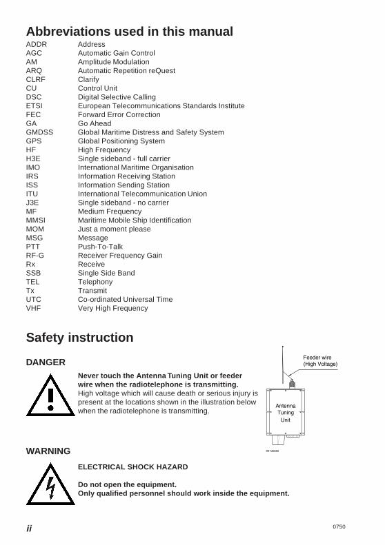
Never touch the Antenna Tuning Unit or feederwire when the radiotelephone is transmitting.High voltage which will cause death or serious injury ispresent at the locations shown in the illustration belowwhen the radiotelephone is transmitting.
ELECTRICAL SHOCK HAZARD
Do not open the equipment.Only qualified personnel should work inside the equipment.
UnitTuning
Antenna
Feeder wire(High Voltage)
99-126550
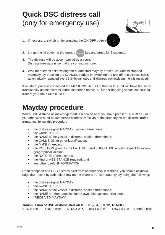
Quick DSC distress call(only for emergency use)
1. If necessary, switch on by pressing the ON/OFF button
2. Lift up the lid covering the orange key and press for 3 seconds.
3. The distress will be accompanied by a sound.Distress message is sent at the continuous tone.
4. Wait for distress acknowledgement and start mayday procedure. Unless stoppedmanually, by pressing the CANCEL softkey or switching the unit off, the distress call isautomatically repeated every 3½-4½ minutes until distress acknowledgement is received.
If an alarm panel is connected the MF/HF DISTRESS button on this unit will have the samefunctionality as the distress button described above. All further handling should continue infront of your main MF/HF DSC.
Mayday procedureWhen DSC distress acknowledgement is received after you have pressed DISTRESS, or ifyou otherwise need to commence distress traffic via radiotelephony on the distress trafficfrequency, follow this procedure:
• the distress signal MAYDAY, spoken three times;• the words THIS IS;• the NAME of the vessel in distress, spoken three times;• the CALL SIGN or other identification;• the MMSI if needed;• the POSITION given as the LATITUDE and LONGITUDE or with respect to known
geographical location,• the NATURE of the distress;• the kind of ASSISTANCE required; and• any other useful INFORMATION
Upon reception of a DSC distress alert from another ship in distress, you should acknowl-edge the receipt by radiotelephony on the distress traffic frequency, by doing the following:
• the distress signal MAYDAY;• the words THIS IS;• the NAME of the vessel in distress, spoken three times;• the NAME or other identification of own ship, spoken three times;• “RECEIVED MAYDAY”.
Transmission of DSC distress alert on MF/HF (2, 4, 6, 8, 12, 16 MHz)2187.5 kHz, 4207.5 kHz, 6312.0 kHz, 8414.5 kHz, 12577.0 kHz, 16804.5 kHz
0750 v

1 2 3 4 5
6 7 8 9 10
The MF/HF at a glance(CU5110)
1. Display.2. Dimming button.3. Mode button used to.
toggle between modes.4. Menu button.
Access to the menu system. 5. Keyboard.6. Loudspeaker.7. DISTRESS button.
Protected by shield. To use,lift the shield and press for 3 seconds.
8. Soft keys. The function of each key is described inits respective field in the display aboveeach key.
9. Adjust/Tune. Multi purpose rotary knob.Controls backlight, frequency and RXtune range.
10. ON/OFF / VOLUME control
vi 0750

10750
ContentsIntroduction ............................................................................................................................. iii
About this manual ................................................................................................................ iiiAbbreviations used in this manual ..................................................................................... ivSafety instruction ................................................................................................................ iv
Quick DSC distress call ........................................................................................................... v
Mayday procedure .................................................................................................................... v
The MF/HF at a glance (CU5110) ........................................................................................... vi
1 MF/HF Fundamental info ................................................................................................... 2
2 Basic functions .................................................................................................................. 32.1 Powering MF/HF ......................................................................................................... 32.2 Speaker volume .......................................................................................................... 32.3 Switches loudspeaker On/Off ..................................................................................... 32.4 Change output power ................................................................................................. 32.5 Squelch On/Off ........................................................................................................... 32.6 Dimming ...................................................................................................................... 42.7 Change mode .............................................................................................................. 42.8 How to operate the menu ........................................................................................... 42.9 How to make a call to a coast station ........................................................................ 52.10 Telephony display functions ....................................................................................... 5
3 Voice call operation ........................................................................................................... 63.1 Operating MF/HF radio communication ..................................................................... 63.2 Listening for calls from a coast station ....................................................................... 63.3 Enter Rx/Tx frequency ................................................................................................ 73.4 Channel entry .............................................................................................................. 83.5 Select a channel from the station table .................................................................... 103.6 Re-tune the Antenna tuner ....................................................................................... 11
4 DSC operation .................................................................................................................. 124.1 DSC main .................................................................................................................. 124.2 DSC setup ................................................................................................................. 134.3 Receiving a Distress Call ......................................................................................... 154.4 Receiving an Individual call ...................................................................................... 164.5 Sending a test call .................................................................................................... 184.6 Calling a coast station .............................................................................................. 204.7 Calling a ship ............................................................................................................ 224.8 Sending an area call ................................................................................................. 244.9 Repeat a call ............................................................................................................. 264.10 Composed DSC calls ............................................................................................... 274.11 DSC call menu .......................................................................................................... 294.12 Geographic Area Computation ................................................................................. 29
5 User setup ......................................................................................................................... 30
6 Data call ............................................................................................................................ 30
7 Scanning ........................................................................................................................... 31
8 Menu tree .......................................................................................................................... 32
9 Installation ........................................................................................................................ 349.1 Compass safe distance ............................................................................................ 34

2
Bas
ic
1 MF/HF Fundamental infoPropagation of MF and HF Radio Waves.MF/HF radiocommunications provide a medium and long range service. The 1.6-4 MHzmarine band is intended primarily for coastal operation beyond normal VHF communicationrange. A reliable range of more than 150 nautical miles can be expected in most areas in thedaytime, more in the nighttime. Propagation of the radio waves in this band is mainly byground waves i.e. the waves from the transmitter aerial follow the earth’s curvature to thereceiver aerial. The high frequency range 4 - 30 MHz can provide communication forhundreds or even thousands of nautical miles. The long range is achieved by sky wavesreflected from the ionosphere. Propagation of the radio waves depends on a number offactors such as frequency, time of day, time of year, and solar activity. The channelsallocated to the maritime mobile service in the HF range are divided into a number of bands:4, 6, 8, 12, 16, 18, 22, 25 MHz to allow a suitable frequency band to be selected for commu-nication dependent on distance and time of day.
RadiotelephonyThe mode of emission used for telephony transmissions in the marine bands is SSB (single-sideband, J3E). On the international distress frequency 2182 kHz compatible AM (amplitudemodulation, H3E) may be used in addition for communication with non-GMDSS ships. AMmode is used also when receiving broadcasting. The frequencies for radiotelephone distressand safety traffic in the HF bands are 4125 kHz, 6215 kHz, 8291 kHz, 12290 kHz, and 16420kHz. Working frequencies for public correspondence with coast stations are arranged in pairsfor duplex/semi-duplex operation. For the HF bands these channels are allocated numbersby ITU on an international basis. In addition a number of simplex frequencies are available ineach band for ship-to-ship communication.
DSCDSC (Digital Selective Calling) is an automatic calling system which allows a specific stationto be contacted and made aware that a station wishes to communicate with it. In addition tocalls to specific stations the system can also be used to call groups of ships and this is ofsignificance for its use for DSC distress alerting. DSC is an alerting signal only and thecommunication which follows the call is made on an appropriate frequency band usingradiotelephony. The frequencies for DSC distress and safety calling are 2187.5 kHz, 4207.5kHz, 6312 kHz, 8414.5 kHz, 12577 kHz, and 16804.5 kHz. Calling frequencies for publiccorrespondence with coast stations are arranged in pairs, both international and nationalfrequencies are assigned. In addition the frequency 2177 kHz may be used for ship-to-shipcalling.
0750

3
Bas
ic
2 Basic functions
2.1 Powering MF/HFThe MF/HF is turned on by a single press on the ON/OFF/Volume button.
The MF/HF is turned off by pressing the ON/OFF/Volume button for 4 seconds.
Always indicated by a count down window in the information display, except if theradio is powered down in distress mode.
Any connected devices (Alarm Panel, Handset, Control Units) will be operationalonly if the MF/HF is powered.
Start-up display is last used mode.
Note: The equipment should always be switched on while at sea in order tomaintain continuous DSC watch.
2.2 Speaker volumeThe volume in the loudspeaker (internal and external) is adjusted by turning theVOLUME control. The volume level is visualized in the display. The volume canbe adjusted to a mute mode by turning the volume control left.
2.3 Switches loudspeaker On/OffSwitches loudspeaker on/off
The loudspeaker symbol in the display will show if the loudspeaker is on or off.
2.4 Change output powerChanges between ‘HIGH POWER’ and ‘LOW POWER’.
DSC and Telex calls are automatically sent in ‘HIGH POWER’.
2.5 Squelch On/OffChanges between squelch on and off, indicated in the telephony display by‘SQUELCH’ and squelch off (no indication). When squelch is on the receiver ismuted in speech pauses.
Squelch is automatically set to off by a change of RX frequency except duringscanning.
0750

4
Bas
icSquelch is automatically set to on when scanning is activated and to off whenscanning is deactivated.
May be switched on and off during scanning.
Always off in AM and SSB Remote mode.
2.6 DimmingTo adjust backlight intensity the dim button is pressed.
2.7 Change modeWith the mode button different operation modes can be selected.
Toggle the button to choose between SSB TELEPHONY, AM BROADCAST,DSC, and SSB REMOTE.
Note: When in AM BROADCAST mode the transceiver cannot be keyed.
2.8 How to operate the menu
Press the Menu button
Main menu:The 4 soft keys at the bottom of the display will havedifferent functionality depending of the menu items.Navigate the menu by using up- and down key.Press OK when the select bar is at the preferred menuitem.Press CANCEL if you want to leave the main menu.
Quick select:In the main menu it is also possible to select a menu itemby pressing the corresponding number key on the keypad.
In a sub menuPress any soft key to choose operation.Press cancel to return to previous menu.
0750

5
Bas
ic
2.9 How to make a call to a coast stationWait until transmission of the traffic list has finished and the channel is free. Call the coaststation on the working frequency on which the traffic list was received or as instructed by thecoast station.
• Hook off the handset.• Press the PTT key on the handset when speaking.
Say:• <Called station’s name (3 times)>• ‘This is’ <Your ship’s name (3 times)>• ‘Over’
• Release the PTT key to listen.• When answered:
Follow the instructions from the coast station. The coast station may ask for furtheridentification, information on position and next port of call, and may suggest anotherworking channel for the traffic to follow. If the coast station is not ready to receive trafficimmediately it may ask you to wait for a specific number of minutes.
PTT only when you are talking. If on a simplex channel (in other words, a channelthat can carry only one transmission at a time), always say “Over” just beforereleasing.
2.10 Telephony display functions
0750

6
Det
ail
3 Voice call operation
3.1 Operating MF/HF radio communicationThe MF/HF is operated by means of a handset.
To bring the MF/HF in transmission mode the handset must be hooked off and the PTTbutton on the handset has to be pressed. Transmission is indicated by the lighted TXindicator.
Receive mode is always reached by releasing the PTT button.
PTT
PTT
Press PTT Release PTThooked offhooked on
HandsetHandset
Transmit and receive is performed on the frequencies or channels shown in the telephonedisplay.
3.2 Listening for calls from a coast stationCoast stations transmit traffic lists consisting of call signs/names of the ships for which theyhave traffic.The traffic lists are sent at specified times and at intervals of typically two hours. They arebroadcasted on the normal working frequencies from the coast station. Ships should, as faras possible, listen to the traffic lists transmitted by relevant coast stations. On hearing theircall sign they should establish communication as soon as they can do so.
1. Select the appropriate station.2. Select the channel on which traffic lists are transmitted.3. Switch loudspeaker on and adjust volume to an appropriate level.
On HF verbal traffic lists are transmitted in more frequency bands simultaneously. Search forthe channel with the best propagation conditions.
0750
7
Bas
ic
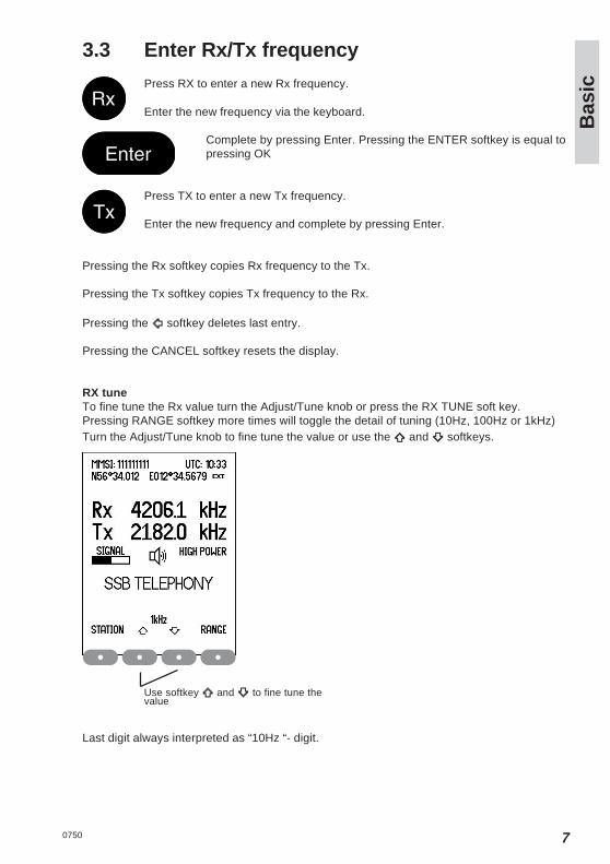
3.3 Enter Rx/Tx frequency
Press RX to enter a new Rx frequency.
Enter the new frequency via the keyboard.
Complete by pressing Enter. Pressing the ENTER softkey is equal topressing OK
Press TX to enter a new Tx frequency.
Enter the new frequency and complete by pressing Enter.
Pressing the Rx softkey copies Rx frequency to the Tx.
Pressing the Tx softkey copies Tx frequency to the Rx.
Pressing the softkey deletes last entry.
Pressing the CANCEL softkey resets the display.
RX tuneTo fine tune the Rx value turn the Adjust/Tune knob or press the RX TUNE soft key.Pressing RANGE softkey more times will toggle the detail of tuning (10Hz, 100Hz or 1kHz)Turn the Adjust/Tune knob to fine tune the value or use the and softkeys.
Last digit always interpreted as “10Hz “- digit.
Use softkey and to fine tune thevalue
0750
8
Bas
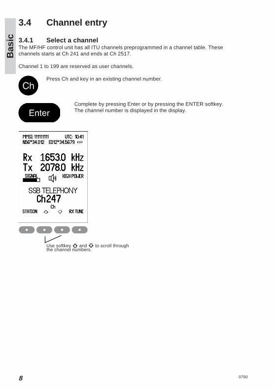
ic3.4 Channel entry
3.4.1 Select a channelThe MF/HF control unit has all ITU channels preprogrammed in a channel table. Thesechannels starts at Ch 241 and ends at Ch 2517.
Channel 1 to 199 are reserved as user channels.
Press Ch and key in an existing channel number.
Complete by pressing Enter or by pressing the ENTER softkey.The channel number is displayed in the display.
Use softkey and to scroll throughthe channel numbers.
0750
9
Bas
ic
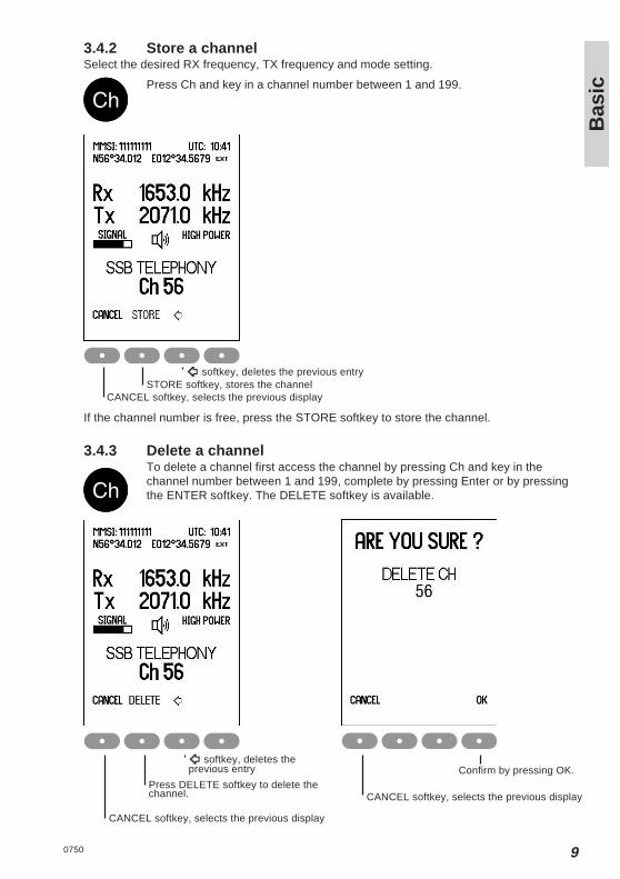
3.4.2 Store a channelSelect the desired RX frequency, TX frequency and mode setting.
Press Ch and key in a channel number between 1 and 199.
softkey, deletes the previous entrySTORE softkey, stores the channel
CANCEL softkey, selects the previous display
If the channel number is free, press the STORE softkey to store the channel.
3.4.3 Delete a channelTo delete a channel first access the channel by pressing Ch and key in thechannel number between 1 and 199, complete by pressing Enter or by pressingthe ENTER softkey. The DELETE softkey is available.
softkey, deletes theprevious entry
Press DELETE softkey to delete thechannel.
CANCEL softkey, selects the previous display
CANCEL softkey, selects the previous display
Confirm by pressing OK.
0750

10
Bas
ic3.4.4 Replace a channelSelect the desired RX frequency, TX frequency and mode setting.
Press Ch and key in a channelnumber between 1 and 199.
Press the REPLACE softkey to store thechannel.
softkey, deletes theprevious entry
REPLACE softkey, to convert to thenew RX and TX frequencies.
CANCEL softkey, selects the previous display
3.5 Select a channel from the station tablePress the STATION softkey in the Telephony display.
Station names are shown
Steps to the previous/next stationin alphabetic order
CANCEL softkey, selects the previous display
Selects the station
Steps to the previous/next stationCANCEL softkey, selects the previous display
Selects the station andreturns to telephony display
Channels allocated the selected station isshown
The radio is ready for use on the selected channel.
0750

11
Bas
ic
3.6 Re-tune the Antenna tunerPress the button ‘0’ for re-tuning the antenna tuner.
Also TX tuning is done automatically the first time the transmitter is keyed on anew frequency and before any DSC transmission.
0750

12
Det
ail
4 DSC operation
4.1 DSC mainPress the Menu button
Using the Down key and press OK when the select bar is at the preferred menu, or use quickselect.
DSC CALL - Alternative press Mode button until DSC mode, and press DSC CALL softkey.
DSC CALLSelect 1. DSC CALL. Opens DSC transmitter menu. From here it is possible to make routinecalls: COAST STATION, SHIP and special calls: AREA, DISTRESS, INDIVIDUAL, GROUPand TEST CALL.
DSC LOGSelect 2. DSC LOG. Opens a menu to the DSC LOG where DSC calls are stored. In thismenu, received distress calls, other received calls and transmitted calls, sorted by time canbe read separately. Received calls are deleted after 48 hours.
COMPOSED DSC CALLSSelect 3. COMPOSED DSC CALLS. Opens the COMPOSED DSC CALLS menu. In themenu complete DSC calls can be composed and stored for later used, or already storedDSC calls can be selected.
0750

13
Det
ail
Use CHANGE softkey - to change setup
Use CANCEL softkey - to return to previous display
Change LAT/LON - to manually enter position if no GPS positionChange TIME - to set real time clock if no GPS time and date
TIME and POSITION TIME disappear when information is updated via the NMEA interface.If not updated via the NMEA interface DATE and TIME must be set manually each time theequipment is switched on.An alarm is given if position data is not received via the NMEA interface for 30 seconds. Inthis case position information must be entered manually. In case of manual input an alarm isgiven when the position information is more than 4 hours old. Any position information isdeleted if not updated for 23½ hours.
4.2 DSC setupPress the Menu button
Select 5. SETUP.Select 1. DSC SETUP.
Steps to the next
0750
14
Det
ail
Set answer back modeAUTO ACKNOWLEDGEMENT = ON:Transmission of acknowledgement is initiated automatically when a direct call, polling orposition request call is received.AUTO ACKNOWLEDGEMENT = OFF:Manuel acknowledgement only. Direct calls initiated by the ship can be carried through;direct calls from coast stations cannot (factory default).
Note: The purpose is to enable the user to prevent automatic transmissions, e.g. when theship is in port.
Set auto position transmitAUTO POSITION RESPONSE = ON:Position information is included in direct calls and position request acknowledgementsAUTO POSITION RESPONSE = OFF:Position information is excluded in direct calls and position request acknowledgements
Set auto channel switchAUTO CHANNEL SWITCH = ON:Possible for automatic procedures to change frequencies for requests received on distressfrequencies .AUTO CHANNEL SWITCH = OFF:Only manual frequency change, except for semi/auto requests.
0750

15
Det
ail
4.3 Receiving a Distress CallThe DSC Watch Receiver keeps continuous watch on the distress and safety frequency2187.5 kHz. Reception of a distress or urgency call is indicated by a specific sound signalwhich continues until a key is pressed. Additional DSC channels can be used if 6-channelscan has been enabled, see chapter “Watch keeping receiver”.
Ships receiving a distress alert from another ship should prepare for receiving the subse-quent distress communication on the telephony distress frequency in the same band in whichthe DSC call was received.
Press to read the call
Select distresscall options
Selects older/newer callReturns to previous telephony display
Returns to previous telephony display
Wait for a short interval in order to give a coast station time to acknowledge the DSC distressalert first. Then, if within range and able to assist, acknowledge the receipt of the distressalert by radiotelephony:
Press the handset key and say:• the distress signal MAYDAY;• the words THIS IS;• the NAME of the vessel in distress, spoken three times;• the NAME or other identification of own ship, spoken three times;• “RECEIVED MAYDAY”.
Press to connect
0750
16
Det
ail
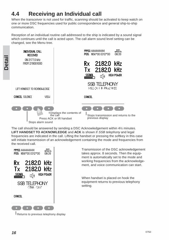
4.4 Receiving an Individual callWhen the transceiver is not used for traffic, scanning should be activated to keep watch onone or more DSC frequencies used for public correspondence and general ship-to-shipcommunication.
Reception of an individual routine call addressed to the ship is indicated by a sound signalwhich continues until the call is acted upon. The call alarm sound level setting can bechanged, see the Menu tree.
Stops alarm sound
Displays the contents ofthe call
Press ACK or lift handset
The call should be answered by sending a DSC Acknowledgement within 4½ minutes.LIFT HANDSET TO ACKNOWLEDGE and ACK is shown if SSB telephony and legalfrequencies are indicated in the call. Lifting the handset or pressing the softkey in this casewill initiate transmission of an acknowledgement containing the mode and frequencies fromthe received call.
Returns to previous telephony display
Stops transmission and returns to theprevious display
Transmission of the DSC acknowledgementtakes approx. 8 seconds. Then the equip-ment is automatically set to the mode andworking frequencies from the acknowledge-ment, and voice communication can start.
When handset is placed on hook theequipment returns to previous telephonysetting.
0750
17
Det
ail
Direct Dial Calls:Some coast stations provide automatic connection from the public switched telephonenetwork allowing a telephone subscriber to call the ship directly without operator interventionat the coast station.
Note: Auto Acknowledgement must be On to allow automatic connection, see DSC StatusDisplay.
An acknowledgement is initiated immediately when a Direct Dial call is received. Thehandset should be lifted off hook within 1 minute which will initiate a DSC call on the workingfrequency. This call is used by the coast station for channel quality evaluation. Whenacknowledgement is received telephone conversation can start.
When the handset is placed on hook after a Direct Dial call a DSC call indicating ‘End of call’is send to terminate the connection. The coast station may respond with a DSC Callindicating the chargeable duration of the connection.
0750

18
Det
ail
4.5 Sending a test callThis call type is intended for test of the DSC system on distress and safety frequencies.
Press the Menu button.
Select OK Select TEST CALLtype
Insert the number in the call
Backspace, deletes last digit
Selects a submenu where a prepro-grammed coast station can be selected
Key in the nine digit MMSI number of the nearest coast station which can accept and reply toDSC test calls.
Navigate the menu by using Up-and Down key
Select OK
0750

19
Det
ail
Select the DSCfrequencies
Start transmission ofthe call
Transmission of a DSC call on MF/HF takes approx. 8 seconds. The coast station shouldanswer the call by sending a DSC Acknowledgement within 4 1/2 minutes. No furthercommunication is intended to take place.
Steps between DSCdistress frequencies
Displays the contents ofthe acknowledgement
0750

20
Det
ail
4.6 Calling a coast station
Press the Menu button andselect 1. DSC CALL
Insert the numberin the call
Some coast stations provide automatic connection with the public switched telephonenetwork. To use this facility select PHONE NO and key in the telephone number. Otherwise:Key in the nine digit MMSI number of the wanted coast station.
Selects a submenu where a pre-programmed coast station can beselected
Select individualroutine call type
Backspace,deletes last figure
Select COAST STATIONcall type
Select mode
Steps between modes
0750
21
Det
ail
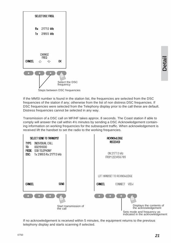
If the MMSI number is found in the station list, the frequencies are selected from the DSCfrequencies of the station if any; otherwise from the list of non distress DSC frequencies. IfDSC frequencies were selected from the Telephony display prior to the call these are default.Distress frequencies cannot be selected in any way.
Transmission of a DSC call on MF/HF takes approx. 8 seconds. The Coast station if able tocomply will answer the call within 4½ minutes by sending a DSC Acknowledgement contain-ing information on working frequencies for the subsequent traffic. When acknowledgement isreceived lift the handset to set the radio to the working frequencies.
Start transmission ofthe call
Displays the contents ofthe acknowledgement
Sets mode and frequency asindicated in the acknowledgement
If no acknowledgement is received within 5 minutes, the equipment returns to the previoustelephony display and starts scanning if selected.
Select the DSCfrequency
Steps between DSC frequencies
0750

22
Det
ail
4.7 Calling a shipPress the Menu button andselect 1. DSC CALL.select 2. SHIP.
Key in the nine digit MMSI number of the wanted ship.
Insert the numberin the call
Backspace, deletes last digit
Direct Dial Calls:If a phone number was included in the call then immediately after reception of the acknowl-edgement the DSC call is repeated on the working frequency. This call may be used by thecoast station for channel quality evaluation. If the channel quality evaluation indicates thatcommunication will be satisfactory, the coast station sends a DSC acknowledgement andstarts dialing the subscriber number. Dialing tones may be heard in the speaker or handset.
When the handset is placed on hook after a Direct Dial call a DSC call indicating ‘End of call’is send to terminate the connection. The coast station may respond with a DSC call indicat-ing the chargeable duration of the connection.
0750

23
Det
ail
Displays the contents ofthe acknowledgement
Sets mode andfrequency as indicated inthe acknowledgement
Normally 2177 kHz is used for intership DSC calls. In addition user programmed DSCfrequencies may be selected. If DSC frequencies were selected from the Telephony displayprior to the call these are default. Distress frequencies cannot be selected in any way.
Transmission of a DSC call on MF/HF takes approx. 8 seconds. The called ship is supposedto answer the call within 4½ minutes by sending a DSC Acknowledgement containinginformation on working frequencies for the subsequent traffic. When acknowledgement isreceived lift the handset to set the radio to the working frequencies.
Starts transmissionof the call
If no acknowledgement is received within 5 minutes, the equipment returns to the previoustelephony display and starts scanning if selected.
Insert the workingfrequencies in the call
Select the DSCfrequency
Steps between DSC frequencies
A working channel shall be proposed when calling another ship.
Selects telephony display forchange of working frequencies
0750

24
Det
ail
4.8 Sending an area callThis call type is used for announcing a vital safety or urgency message.
Press the Menu button andselect 1. DSC CALLselect 3. AREA
Enter area radius(nm)
Select
Steps between SAFETYand URGENCY
Select Select
Steps between S/N Steps between E/W
softkey, delete theprevious entry
0750
25
Det
ail
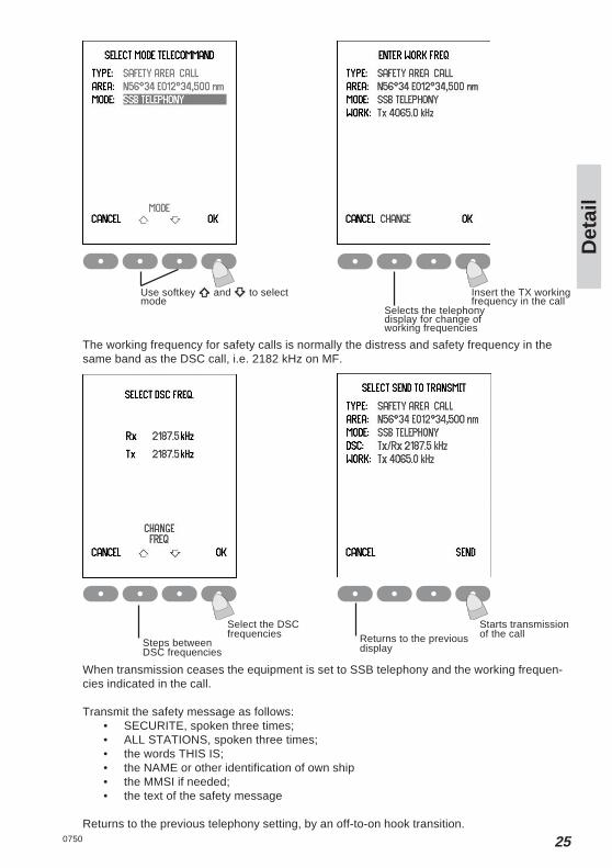
When transmission ceases the equipment is set to SSB telephony and the working frequen-cies indicated in the call.
Transmit the safety message as follows:• SECURITE, spoken three times;• ALL STATIONS, spoken three times;• the words THIS IS;• the NAME or other identification of own ship• the MMSI if needed;• the text of the safety message
Returns to the previous telephony setting, by an off-to-on hook transition.
Starts transmissionof the callReturns to the previous
display
Use softkey and to selectmode
Steps betweenDSC frequencies
Insert the TX workingfrequency in the call
Selects the telephonydisplay for change ofworking frequencies
The working frequency for safety calls is normally the distress and safety frequency in thesame band as the DSC call, i.e. 2182 kHz on MF.
Select the DSCfrequencies
0750

26
Det
ail
4.9 Repeat a callPress the Menu buttonand select 2. DSC LOG
Select TX call logSelects non-distress RX call log
Selects Distress RX call log
Returns to previous display
RE-SEND starttransmission of the call
The TX calls log has capacity for storing 20 transmitted calls. The oldest call is deleted whenthe capacity is exceeded.RE-SEND does not appear for acknowledgement calls and distress format and categorycalls.
0750

27
Det
ail
0750
4.10 Composed DSC callsThe equipment enables the possibility to pre-compose a DSC routine call for later use.
Press the Menu button andselect 3. COMPOSED DSC CALLS
To enter a new pre-composed DSC routine message press the MODIFY soft key followed bypressing the ADD soft key. Note that you will have to scroll down to an empty messagebefore the MODIFY soft key appears.
Select MODIFY
Returns to previous display
Select between a call to coast station, ship or group by using the Up/Down soft keys andselect OK. Alternatively use quick select by pressing either the 1, 2 or 3 button.
Select ADD tomake a new entry
Select OK
Returns toprevious display
Steps up or downbetween types
Returns to previous display

28
Det
ail
0750
The user is now asked for MMSI, Mode, frequency. When all the information is entered theuser is asked to enter a name.
Select OK tomake a new entry
To delete an already stored DSC routine call press the MODIFY soft key followed byDELETE.
Send an already stored DSC routine call by using the Up/Down soft keys and press OK.
Select OK
Select OK tomake a new entry
Steps up or downbetween composed DSC calls

29
Det
ail
0750
4.11 DSC call menuMENU1. DSC CALL 1. COAST STATION 1. WITH PHONE NO MMSI Phone no MODE DSC freq
2. WITHOUT NO MMSI MODE DSC freq2. SHIP MMSI MODE Working freq DSC freq3. AREA POS CATEGORY MODE Working DSC freq
RADIUS f req4. DISTRESS 1. ALERT MODE Nature of POS DSC freq
distress * 2. RELAY 1. COAST STATION MMSI POS
2. SHIP MMSI3. AREA POS
RADIUS5. INDIVIDUAL MMSI CATEGORY MODE FREQUENCY DSC freq
POSITION6. GROUP MMSI MODE Working freq DSC freq7. TEST CALL 1. SHIP TEST CALL MMSI DSC freq
2. COAST STATION MMSI DSC freq TEST CALL
*) Nature of distress:FIRE, EXPLOSION, FLOODING, COLLISION, GROUNDING, DANGER OF CAPSIZING, SINKING, DISABLED AND ADRIFT, UNDESIGNATED (default), ABANDONING SHIP, PIRACY, MAN OVERBOARD, EPIRB EMISSION (Distress Relay only)
Ship in distress
MODE Nature of distress *
4.12 Geographic Area ComputationWhen transmitting a geographical area call, the user is requested to enter the position of theship (x,y) and the radius of interest r. This information is transformed to a square with acorner point and the length of its sides and . Finally the DSC message istransmitted over the air. See the figure below for an illustration of the relation between theuser input (the white circle) and the information transmitted over the air (the grey square).
The center point is the position of the ship measured in degrees and minutes, whereas theradius of interest is given in nautical miles.
The corner point of the square and the length of its sides is given in degrees. Note that thesevalues are rounded to degrees, and due to the requirement that the square shall include theentire circle; this will result in a slightly larger area than defined by the user input.
Also note that special handling is required when close to the poles. If the latitude of thecorner point is transformed to a value greater that 90° then is set to 90° and the length ofthe square is reduced correspondingly. If the length of the square is greater than 90°then is set to 90°.
30
Det
ail
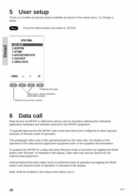
5 User setupThere is a number of special setups available as shown in the setup menu. To change asetup:
Press the Menu button and select 5. SETUP
6 Data callData service via MF/HF is offered by various service providers utilizing their individualapplication hardware and software external to the MF/HF equipment.
To operate data service the MF/HF radio must have been prior configured to allow operatorselection of Remote mode of operation.
This paragraph refers only to the operational part on the radio side. For details on theoperation of the data service application equipment refer to the suppliers documentation.
To prepare the MF/HF for a data call select Remote mode of operation by toggling the Modebutton until “Remote” is indicated in the display. Data calls may now be setup from theexternal data equipment.
Having finalized the data call(s) revert to preferred mode of operation by toggling the Modebutton until required mode of operation is indicated in the display.
Note: Shall be enabled in the setup menu before use !!!
Selects the type
Steps up or down betweenselectable setups
Returns to previous menu
0750

31
Det
ail
0750
7 ScanningTo start scanning the “4” button is pressed.
The last used scanning type is selected and squelch is set to on when scanning is activated.Speaker is set to on if the scanning type is Telephony Watch, Multi Watch or Dual Watch.Scanning is stopped by pressing softkey EDIT or by lifting the handset off hook. For MultiWatch or Telephony Watch scanning stops on the presently scanned telephony channel, forDual Watch and DSC Watch the previous telephony setting is restored. Scanning resumeswhen the handset is placed on hook again.
Scanning types
Telephony watch:Up to 10 telephony channels.Scanning rate is approx. one channel per 2 sec.
Multi watch:A single DSC frequency (normally 2177 kHz) and up to 10 telephony channels.Scanning rate is approx. one channel per 2 s. The DSC frequency is monitored briefly ateach telephony channel shift.
Dual watch:A single DSC frequency (normally 2177 kHz) and the current telephony frequency.The DSC frequency is monitored briefly at approx. each 2 s.
DSC watch:Up to 6 DSC frequencies.Scanning rate is approx. six channels per 2 sec.
Use EDITsoftkey - to edit scanning frequencyUse / softkey - switch to next /previous scanning typeUse CANCELsoftkey - returns to previous telephony setting

32
Det
ail
0750
8 Menu treeMENU1. DSC CALL 1. COAST STATION 1. WITH PHONE NO MMSI Phone no
2. WITHOUT NO MMSI2. SHIP MMSI3. AREA POS CATEGORY MODE
RADIUS4. DISTRESS 1. ALERT MODE Nature of
distress * 2. RELAY 1. COAST STATION MMSI
2. SHIP MMSI3. AREA POS
RADIUS5. INDIVIDUAL MMSI CATEGORY MODE
6. GROUP MMSI MODE Working freq7. TEST CALL 1. SHIP TEST CALL MMSI DSC freq
2. COAST STATION MMSI DSC freq TEST CALL
2. DSC LOG 1. RX DISTRESS2. RX OTHER3. TX CALLS
3. COMPOSED DSC CALLS Select NameModify
4. STATIONS New NAME MODE FREQ.Edit MMSI
CHANNEL5. SETUP 1. DSC SETUP DISTRESS FREQUENCY
AUTO ACKNOWLEDGEMENT ON/OFFAUTO POSITION TRANSMIT ON/OFFAUTO CHANNEL SWITCH ON/OFFTELECOMMAND MEDICAL OFFTELEC. SHIP AND AIRCRAFT OFFLATLONPOSITION TIMEDATETIME
2. RECEPTION 1. EARPIECE Adj. earpiece vol. Level 0-72. RECEIVER TREBLE CUT ON/OFF
SUPPRESSOR ON/OFF3. CALL ALARM Adjust call alarm 0-7
3. OPTIONS Passw ord 1. TX BANDSNew
2. CONFIGURATION EditLSB mode Enable/disableRemote mode Enable/disableBattery Alarm Enable/disable
3. DSC ATU installed YES/NOLanguageRX Test
TX Test
4. FACTORY RESET5. MMSI RESET
4. CONFIG STATUS6 INFO & TEST 1. INFORMATION 1. MMSI
2. VERSIONS 1. SOFTWARE2. HARDWARE
3. ALARMS4. TU SERIAL NUMBER
2. CHECK 1. TX PROTECTION2. INTERFACE 1. SOUND & DISPLAY
2. ALARM PANEL3. NMEA INPUT
3. SELFTEST Manual3. MONITOR 1. POWER TX 2-Tone
2. WR AUDIO

33
Det
ail
0750
MODE DSC freqMODE DSC freqMODE Working freq DSC freqWorking DSC freqfreqPOS DSC freq
POS DSC freq
FREQUENCY DSC freqPOSITIONDSC freq
Serial output enabled/disabledSend dotSend YSend B
Ship in distress
MODE Nature of distress *
34
Inst
alla
tio
n
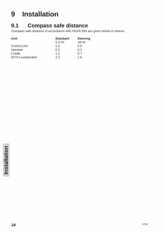
9 Installation
9.1 Compass safe distanceCompass safe distance in accordance with ISO/R 694 are given below in metres.
Unit Standard Steering5.4°/H 18°/H
Control Unit 1.2 0.5Handset 0.3 0.2Cradle 1.1 0.75070 Loudspeaker 2.2 1.6
0750


R&TTE
Doc. no TT99-126011-A
Thrane & Thrane A/SDeclaration of Conformity with R&TTE Directive
The undersigned of this letter declares that the following equipment complies with thespecifications of EC directive 1999/5/EC concerning Radio & Telecommunications TerminalEquipment.
Equipment included in this declarationSAILOR CU5110 Control Unit MF/HF, Black Grey PN = 405110-THRBGSAILOR CU5110 Control Unit MF/HF, T&T Blue PN = 405110-THRBLSAILOR CU5110 Control Unit MF/HF, Green PN = 405110-THRGRSAILOR TU5155 Transceiver Unit MF/HF 150W PN = 405155-THRBKSAILOR ATU5116 Antenna Tuning Unit 150W PN = 405116-THRWH
Equipment ApplicabilitySAILOR SYSTEM 5000 MF/HF 150W is a maritime radio telephone, intended for use in theEØS countries.The system consists of a compact transceiver control unit, a fully remote controlled trans-ceiver unit and an automatic antenna tuning unit.
DeclarationThe requirement with respect to the LVD directive 73/23/EC is met by conforming to the har-monized EU standard EN 60950. The protection requirement with respect to the EMC direc-tive 89/336/EC is met by conforming to the harmonized EU standard EN 60945. Effective useof frequency spectrum is met by conforming to the harmonizied EU standard ETSI EN 300373, EN 300 338, EN 300 067.
ManufacturerThrane & Thrane A/S Lundtoftegårdsvej 93D, DK-2800 Kgs. Lyngby, Denmark
Porsvej 2, DK-9200 Aalborg SV, Denmark
Place and DateAalborg, 06. December 2007
Chief Financial OfficerSvend Åge Lundgaard Jensen
Page 1 of 1
Thrane & Thrane A/S · Lundtoftegårdsvej 93D · DK-2800 Kgs. Lyngby · Denmark
T +45 39 55 88 00 · F +45 39 55 88 88 · [email protected] · www.thrane.com
Bank: Danske Bank · Comp. reg.: 65 72 46 18 · VAT: DK-20 64 64 46