SAI-340A Installation Manual - Sandia Aerospace · specification(s) installation manual, p/n...
30
3700 Osuna Road NE Suite 711 Albuquerque, NM 87109 www.sandia.aero 306502-00 Rev 3 SAI-340A Installation Manual
Transcript of SAI-340A Installation Manual - Sandia Aerospace · specification(s) installation manual, p/n...

3700 Osuna Road NE Suite 711 Albuquerque, NM 87109 www.sandia.aero
306502-00 Rev 3
SAI-340A Installation Manual

1
3700 Osuna Road NE Suite 711 Albuquerque, NM 87109 www.sandia.aero
This document and the information contained herein is the propriety data of SANDIA aerospace Corporation. No part of this document may be transmitted, reproduced, or copied in any form or by
any means without the prior written consent of SANDIA aerospace .
Due to SANDIA aerospace’s continued product and quality improvement programs, information contained in this document is subject to change without prior notice Copyright 2016
SANDIA aerospace Corporation, all right rights reserved.
Printed in USA.
Record of Revision
Revision Date Description Approval 1-ER 12/8/2017 Initial release Brian Gordon 2-ER 12/13/2017 ECN4335 – FAA Feedback on Section 5 Brian Gordon 3-ER 5/25/2018 ECN4372 – Add Panel Type setup page and Gasket Brian Gordon

2
3700 Osuna Road NE Suite 711 Albuquerque, NM 87109 www.sandia.aero
Table of Contents
Section 1 - General Description ..................................................................................................................... 4
1.1 Introduction ................................................................................................................................... 4
1.2 SAI-340A Product Description ....................................................................................................... 4
1.2.1 System Functions ...................................................................................................................... 4
1.2.2 System Interfaces ...................................................................................................................... 5
1.2.3 Unit Outer Dimensions.............................................................................................................. 5 1.3 Specifications ................................................................................................................................. 6
1.3.1 Physical Characteristics ............................................................................................................. 6
1.3.2 Performance Characteristics ...................................................................................................... 6 1.3.3 Certification .............................................................................................................................. 6
1.4 Environmental Qualification Form for the SAI-340A ..................................................................... 7 Section 2 - Installation Considerations ........................................................................................................... 8
2.1 General .......................................................................................................................................... 8
2.2 Handling Considerations ................................................................................................................ 8
2.3 Certification Considerations ........................................................................................................... 8
2.3.1 Installation Approval ................................................................................................................. 8
2.3.2 EFIS Standby Applications ....................................................................................................... 8 2.3.3 Substitution of Rate-Of-Turn Indicator ...................................................................................... 9 2.3.4 Battery Operation ...................................................................................................................... 9
2.3.5 Functional Dependencies .......................................................................................................... 9 2.3.6 Operational Limitations ........................................................................................................... 10
2.3.7 TSO Deviations ...................................................................................................................... 11
2.3.8 Degraded Mode Operation ...................................................................................................... 11 2.4 Pneumatic Source ......................................................................................................................... 12
2.5 Cooling Considerations ................................................................................................................ 12
Section 3 – Installation Procedures .............................................................................................................. 13
3.1 General ........................................................................................................................................ 13
3.2 Equipment Required..................................................................................................................... 13
3.2.1 Supplied .................................................................................................................................. 13
3.2.2 Operational Software .............................................................................................................. 13
3.2.3 Required, But Not Supplied..................................................................................................... 13 3.3 Mounting Hole ............................................................................................................................. 14
3.4 Mounting Bracket Installation ...................................................................................................... 14
3.5 Wiring Installation ....................................................................................................................... 15
3.6 Pneumatic Line Installation .......................................................................................................... 16
3.7 Unit Mounting ............................................................................................................................. 18
3.8 System Configuration ................................................................................................................... 19
3.8.1 Initial Power On ...................................................................................................................... 19
3.8.2 Entry & Exit From Setup Mode ............................................................................................... 19 3.8.3 Default Baro Setting ................................................................................................................ 20
3.8.4 Panel Type .............................................................................................................................. 20

3
3700 Osuna Road NE Suite 711 Albuquerque, NM 87109 www.sandia.aero
3.8.5 Setup Pages ............................................................................................................................. 20
Section 4 - Instructions for Continued Airworthiness ................................................................................... 22
4.1 ICA General ................................................................................................................................. 22
4.2 Airworthiness Limitations ............................................................................................................ 22
4.2.1 Battery Limitations ................................................................................................................. 22
4.2.2 Altimeter Limitations .............................................................................................................. 22
4.3 Battery Maintenance .................................................................................................................... 22
4.3.1 Full-Duration Load Test .......................................................................................................... 22
4.3.2 Battery Replacement Procedure ............................................................................................... 23 4.4 Airspeed and Altimeter Test & Calibration ................................................................................... 25
4.4.1 Altimeter System Test and Inspection ..................................................................................... 25 4.4.2 Airspeed Trim Procedure ........................................................................................................ 25 4.4.3 Altitude Trim Procedure .......................................................................................................... 25
4.5 Troubleshooting ........................................................................................................................... 26
Section 5 - Pilot Operating Handbook .......................................................................................................... 27
List of Illustrations
Figure 1 – Unit Outer Dimensions ................................................................................................................. 5
Figure 2 – Unit Front and Rear Views ......................................................................................................... 13
Figure 3 - Instrument Cutout ........................................................................................................................ 14
Figure 4 – Front & Rear Mounting Bracket .................................................................................................. 15
Figure 5 - Sub-D Back-Shell ........................................................................................................................ 15
Figure 6 - Wiring Diagram .......................................................................................................................... 16
Figure 7 – Supplied Pneumatic Fitting ......................................................................................................... 17
Figure 8 – Thread Depth Limit .................................................................................................................... 17
Figure 9 - Unit Mounting With Tab/Slot Cutaway ....................................................................................... 18
Figure 10 - Power On Screen ....................................................................................................................... 19
Figure 11 – Setup Mode Menu..................................................................................................................... 20
Figure 12 - Li-Poly Battery Pack ................................................................................................................. 23
Figure 13 - Li-Poly Battery Connections ...................................................................................................... 23
Figure 14 - Power On Screen ....................................................................................................................... 29
4
3700 Osuna Road NE Suite 711 Albuquerque, NM 87109 www.sandia.aero
Section 1 - General Description
1.1 Introduction This manual describes the installation of the SANDIA aerospace SAI-340A Attitude Indicator.
It is intended for use by FAA certified repair stations to install the SAI-340A indicator and includes both mechanical and electrical installation information.
System configuration, continued airworthiness and sample POH are included. The installer must ensure that all functions are operating properly according to their intended purpose in their particular installation.
1.2 SAI-340A Product Description The SAI-340A Attitude Indicator is a panel mounted attitude, airspeed, altitude, vertical speed and slip. The instrument is self-contained and directly incorporates all of the sensors required to measure and display the listed flight parameters.
All information is displayed on a color 3.5” diagonal LCD display in traditional aerospace symbology. The unit also contains a rechargeable battery capable of providing continued operation in the event of aircraft electrical failure.
1.2.1 System Functions
The SAI-340A performs the following functions: � Display of Indicated Airspeed (Knots or Mph) � Display of Barometric Altitude (Feet) � Display of Roll & Pitch (Fixed Pointer Format, Degrees) � Display of Slip Indication (Degrees) � Display of Vertical Speed Indication (feet per minute)
� Pilot Entered Baro Correction (mb or inHg, Configurable Default) � Automatic and Manual Backlight Control (%) � Display of Battery Charge Status (% Remaining) � Display of V-Speed Limitations (Colored Bands) � Altitude Bug (Pilot Adjustable)
Various parameters can be configured by the installer (not pilot accessible): � Configuration of Roll & Tilt Offsets � Configuration of Airspeed and Altitude Trim � Configuration of Airspeed Units � Configuration of V-Speeds � Configuration of Baro Units � Configuration of Baro Default Value � Configuration of Battery Type � IVSI Filter Lag � Air Data Calibration

5
3700 Osuna Road NE Suite 711 Albuquerque, NM 87109 www.sandia.aero
Non TSO’d functions have been verified to not interfere with TSO’d functions.
1.2.2 System Interfaces
Airspeed and altitude are derived from internal pressure sensors that are connected to the aircraft’s pitot and static lines. Airspeed is determined by the pressure difference between the pitot and static ports, while altitude is determined by the pressure on the static port. Altitude is barometrically corrected by the pilot entered baro value prior to being displayed.
Attitude is aided by airspeed to provide better pitch performance during takeoffs and in-flight accelerations and decelerations. TSO performance levels are maintained with or without this additional aiding.
Aircraft power is the only electrical interface present. No communication or data interfaces are provided to other avionic systems in the aircraft.
1.2.3 Unit Outer Dimensions
Figure 1 – Unit Outer Dimensions
6
3700 Osuna Road NE Suite 711 Albuquerque, NM 87109 www.sandia.aero
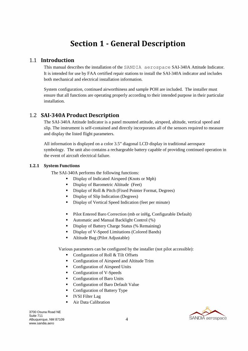
1.3 Specifications
1.3.1 Physical Characteristics
Mounting ...........................................................Standard 3” Round Hole Overall Dimensions ...........................................3.52 x 3.22 x 2.25 in Bezel Dimensions..............................................3.52 x 3.22 x 0.51 in Weight ...............................................................0.8 lbs (Including Battery & Bracket) Pneumatic Fittings .............................................1/16 NPTF (1/8” Barbed Adapters Supplied) Viewing Angle ..................................................60° Left/Right, 45° Up/Down Operating Temp ................................................-20°C to +55°C Power Input .......................................................10-32 VDC Current ..............................................................2 Amp Max
1.3.2 Performance Characteristics
Time to Initialize ...............................................< 3 Minutes Typical Airspeed Range .................................................30 to 400 Knots (30 to 460 Mph) Altitude Range ..................................................-1500 to 35,000 Feet Vertical Speed Range ........................................-5,000 to 5,000 Feet/Min Baro Correction Range (inHg) .........................28.00 to 31.00 inHg Baro Correction Range (mb) .............................948 to 1050 mb Roll/Pitch Accuracy ..........................................1° Static Conditions Roll/Pitch Range ...............................................Unlimited Slip Range .........................................................±7° Displayable Slip Accuracy ....................................................1° Static Conditions Max Roll Rate ...................................................400° / Second Max Sustained G ...............................................6g Roll/Pitch/Slip Resolution .................................Sub-pixel (340 x 240) Battery Type 0 (P/N 306186) ............................Li-Poly, 7.4V, 1300mAh, Heated
Battery Life (-20°C, 100% Brightness) .......0.5 Hours Minimum Battery Life (+23°C, 100% Brightness) ......2.0 Hours Minimum Battery Life (+55°C, 100% Brightness) ......3.0 Hours Minimum Battery Charge Time ...................................4 Hour Typical (From Fully Discharged) Battery Heat Time .......................................15 Minutes Max @ -20°C Cold Soaked
1.3.3 Certification
Airspeed ............................................................TSO-C2d (Type B) Airspeed Limits .................................................Vso, Vs1, Vfe, Vno, Vne, Vyse, Vmc Turn and Slip .....................................................TSO-C3e Bank and Pitch ..................................................TSO-C4c Altimeter ...........................................................TSO-C10b (Type II) Display ..............................................................TSO-C113a AHRS ................................................................TSO-C201 (A5HXT7)
Vertical Speed Indicator ....................................TSO-C8E (Type B) Battery ...............................................................RTCA DO-347 (“Small” Lipo – 4.81Wh) Software Design Assurance ..............................RTCA DO-178C (DAL C) Hardware Design Assurance .............................N/A Environmental ...................................................RTCA DO-160G (See Qual Table) MTBF ................................................................>10,000 hours

7
3700 Osuna Road NE Suite 711 Albuquerque, NM 87109 www.sandia.aero
1.4 Environmental Qualification Form for the SAI-340A NOMENCLATURE SAI-340A Attitude Indicator MODEL/PART NO SAI-340A / 306171-20 TSO NUMBER TSO-C2d (Type B), TSO-C3e, TSO-C4c, TSO-C10b (Type II),
TSO-C113a,TSO-C201 SPECIFICATION(S) INSTALLATION MANUAL, P/N 306502-00 ENVIRONMENTAL QUAL PLAN, P/N 901099-EQTP MANUFACTURER SANDIA AEROSPACE ADDRESS 3700 OSUNA RD NE, SUITE 711, ALBUQUERQUE, NM 87109 DO-160 REVISION REV G (DECEMBER 8, 2010) DATE OF TESTS 2014-2015
CONDITION SECTION DESCRIPTION OF TEST CONDUCTED Temperature
Ground Survival Low Short Term Low Operating Low Ground Survival High Short Term High Operating High In-Flight Loss of Cooling
Altitude Altitude Decompression Overpressure
4.5 4.5.1 4.5.1 4.5.2 4.5.3 4.5.3 4.5.4 4.5.5 4.6 4.6.1 4.6.2 4.6.3
Category A1/C1 -55°C -40°C -20°C +85°C +70°C +55°C Not Applicable 35,000 Feet 8,000 to 35,000 Feet -15,000 Feet
Temperature Variation 5.0 Category C, 2°C / Min
Humidity 6.0 Category A
Shock and Crash Safety 7.0 Category B, AC Type 5, Random
Vibration 8.0 Category S, Zone 2, Curve M
Explosive Atmosphere 9.0 Category X, No Test Performed
Waterproofness 10.0 Category X, No Test Performed
Fluids Susceptibility 11.0 Category X, No Test Performed
Sand and Dust 12.0 Category X, No Test Performed
Fungus 13.0 Category X, No Test Performed
Salt Spray 14.0 Category X, No Test Performed
Magnetic Effect 15.0 Category Z
Power Input 16.0 Category BXX
Voltage Spike 17.0 Category A
Audio Freq Cond Susceptibility 18.0 Category B
Induced Signal Susceptibility 19.0 Category X, No Test Performed Note 1
Radio Freq Susceptibility 20.0 Category WF
Emission of Radio Freq 21.0 Category M
Lighting Induced Transient Susc. 22.0 Category B3K3
Electrostatic Discharge 25.0 Category A Notes:
1) Equipment does not incorporate electrical interfaces to other equipment. Test does not apply.
8
3700 Osuna Road NE Suite 711 Albuquerque, NM 87109 www.sandia.aero
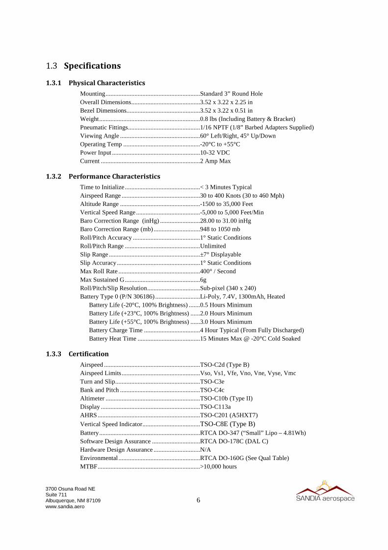
Section 2 - Installation Considerations
2.1 General The SAI-340A provides stand-alone, basic airspeed, altitude, attitude and slip functions. The SAI-340A does not support integration with other avionics systems, nor does it provide complex switching interfaces with other equipment or systems. Installation is limited to power, ground, pitot and static connections.
2.2 Handling Considerations The SAI-340A incorporates sensitive sensor elements that may be damage or degraded by improper handling. Observe the following prior to and during installation:
• Do not apply excessive pressure or vacuum to either the pitot or static pressure ports • Do not insert objects into the pressure ports (other than approved fittings)
• Do not drop, jar or otherwise mechanically shock the unit • Do not scratch or otherwise mar the display or surrounding bezel
• Clean the display only with products approved for LCD screens
• Do not drop, puncture or otherwise tamper with the battery pack
2.3 Certification Considerations
2.3.1 Installation Approval
The conditions and tests for TSO approval of this article are minimum performance standards. Those installing this article, on or in a specific type or class of aircraft, must determine that the aircraft installation conditions are within the TSO standards. TSO articles must have separate approval for installation in an aircraft. The article may be installed only according to 14 CFR Part 43 or the applicable airworthiness requirements.
This article meets the minimum performance and quality control standards required by a technical standard order (TSO). Installation of this article requires separate approval.
2.3.2 EFIS Standby Applications
If installation is being performed on an aircraft with a retro-fit EFIS/PFD installation, the FAA approved installation guidance for that product must be considered when installing the SAI-340A as a backup to those installations. Compatibility with the primary EFIS/PFD must be evaluated and considerations may include:
• Electrical architecture (single / dual bus, multi-engine, etc) • Independent power source requirements
• Electrical load analysis • Mounting location relative to primary instrumentation
• Compatibility of airspeed, altitude, baro setting units relative to the primary instrumentation • Compatibility of roll pointer (fixed pointer vs fixed scale)
9
3700 Osuna Road NE Suite 711 Albuquerque, NM 87109 www.sandia.aero
• Compatibility of environmental qualification levels • Compatibility of software design assurance levels (DAL)
• Compatibility of airspeed limitations (Mmo, variable Vmo/Vne or placarded limits) • Compatibility of HIRF and lightning levels
• Compatibility of Functional Limitations (See section below)
2.3.3 Substitution of Rate-Of-Turn Indicator
The SAI-340A may be eligible to replace the Rate-Of-Turn Indicator in certain applications. Refer to FAA AC 91-75 for additional details.
2.3.4 Battery Operation
The battery sub-system in the SAI-340A is designed to fulfill the needs of an independent power source per 14 CFR 23.1353(h). Considerations are as follows:
• Automatic transition to battery will occur if the externally supplied power drops below approximately 7 VDC.
• A load-test is performed on each power-on cycle - a faulted battery indication will be shown if this test fails.
• Battery operational time is highly dependent on the ambient operating temperature and
backlight intensity settings. See the specifications section in this document for minimum guaranteed operating time under different conditions.
• Reference the SAI-340A Pilots Guide (document number 306503-00) for additional details
on battery operation.
2.3.5 Functional Dependencies
The SAI-340A is not sensitive to external magnetic fields. Altitude indication requires correct static pressure. Airspeed indication requires both correct pitot and correct static pressure. Slip indication has no functional dependencies.
10
3700 Osuna Road NE Suite 711 Albuquerque, NM 87109 www.sandia.aero
2.3.6 Operational Limitations
The following operational limitations apply:
• Geographic limitation: None • Magnetic field sensitivity: None • Lightning direct effects sensitivity: None
• Lightning indirect effects sensitivity: Approved for catastrophic functions • HIRF Susceptibility: Approved for catastrophic functions
• Viewing Angle Limitations: 60° Left / Right, 45° Up / Down
• Displayable Vspeeds: Vne, Vno, Vfe, Vs1, Vso (Vmc, Vyse ME Only) • Maximum displayable airspeed: 400 Knots / 460 Mph
• Minimum displayable airspeed: 30 Knots / 30 Mph • Maximum displayable vertical speed range: -5,000 to 5,000 Feet/Min
• Minimum displayable vertical speed range: -100 to 100 Feet/Min • Maximum displayable altitude: 35,000 Feet • Minimum displayable altitude: -1,500 Feet
• Maximum configurable baro correction: 1050 mb / 31.00 inHg • Minimum configurable baro correction: 948 mb / 28.00 inHg
• Minimum operational duration on battery: 30 Minutes • Maximum roll rate: 400 degrees / second • Maximum operating G force: 6 G
• Battery operation may be inhibited for up to 15 minutes during cold-starts. TSO performance
is met within 10 minutes during cold-starts. • No operational capability on internal battery is possible if the battery is faulted, as shown by a
Red-X over the battery icon. • Battery charging is disabled below approximately 0°C and above 40°C ambient, or when
power input is below approximately 11 volts DC. • If in-Flight alignment is attempted, it must be performed with wings-level non-accelerated
flight conditions.
NOTE: Approximately nine percent of the population has some sort of color vision deficiency (what is commonly called “color blindness”). It should also be noted that the FAA does not test for all potential color deficiencies. (Source TSO-C113a / AS8034)

11
3700 Osuna Road NE Suite 711 Albuquerque, NM 87109 www.sandia.aero
2.3.7 TSO Deviations
TSO deviations are related to environmental test conditions and software certification basis. In both cases, the latest versions of RTCA DO-160 (Revision G) and RTCA DO-178 (Revision C) were utilized in lieu of older guidance.
In certain circumstances, this is a deviation from older TSO and associated MOPS guidance as follows:
TSO’s that reference older versions of DO-160:
• TSO-C2d § c(2)(viii) and corresponding MOPS AS8019 § 5 • TSO-C3e § 6 (g) and corresponding MOPS AS8004 § 5
• TSO-C8E § 6 (g) and corresponding MOPS AS8016A § 5
TSO’s that directly include a list of environmental specifications:
• TSO-C4c § 514.14 and corresponding MOPS AS396B § 3.3, § 3.4, § 3.5, § 4.4, § 7 • TSO-C10B § a(2)(ii) and corresponding MOPS AS392C § 3.3, §7
TSO’s that reference older versions of DO-178:
• TSO-C2d § a(3), §a(3)(i), § c(1)(xi), §c(2)(vii)
• TSO-C3e § 3(e), § 6(h) • TSO-C113a § 3(e), § 6(g)
• TSO-C201 §3(e), § 6(g) and corresponding MOPS DO-334 § 2.1.7.2
• TSO-C8E §3(e), § 6(h)
The above deviations have been FAA approved.
2.3.8 Degraded Mode Operation
Errors will not exceed TSO limit specifications. When a cross check message is present the SAI-340A is considered to be in degraded mode. The TSO tested maneuvers represent typical flight. Degraded mode may occur if a pilot maintains an accelerated frame of reference (i.e. turns) for greater than 3 minutes.
Operation in this Degraded Mode does not imply that attitude availability from the SAI-340A has been lost. During this Degraded Mode, attitude information is always available to the pilot - it is never removed or made un-available unless failure occurs.
When operating in this Degraded Mode, the SAI-340A will show a attitude innacuracies, on the order of ±3.0°. This condition will self-correct once the maneuver is completed.
The limited performance degradation in this mode meets the applicable performance requirements of TSO-C201/DO-334 § 2.2.4.2 (Degraded Mode Accuracy), 2.2.4.2.1 (Degraded Mode Pitch Accuracy), & 2.2.4.2.2 (Degraded Mode Roll Accuracy), for “basic attitude performance”, meaning it is sufficient to maintain positive aircraft control.
12
3700 Osuna Road NE Suite 711 Albuquerque, NM 87109 www.sandia.aero
Therefore, for backup applications where air data is also utilized in the PFD solution, should air data become un-available in a common mode failure scenario, basic attitude performance is maintained by the SAI-340A. This is compliant with 14 CFR 23.1311 § (b) and applicable sections of AC 23-1311.1C.
Degraded Mode operation is defined by TSO-C201/RTCA DO-334 § 2.2.4 as follows:
The intended function of a degraded mode (if provided) is to provide basic attitude performance, despite one or more AHRS failures. A degraded mode is intended to allow a pilot to maintain positive aircraft control while maneuvering under IMC, including IFR en route operations, climbs, descents, holds, fly an instrument approach to minimums, and return the aircraft back to level following an upset.(…)
2.4 Pneumatic Source For operations in IFR conditions, TSO-C16a (or equivalent) pitot and pitot-static tubes must be utilized as the source of pitot and static air pressure.
2.5 Cooling Considerations The SAI-340A does not require any special cooling considerations.
13
3700 Osuna Road NE Suite 711 Albuquerque, NM 87109 www.sandia.aero
Section 3 – Installation Procedures
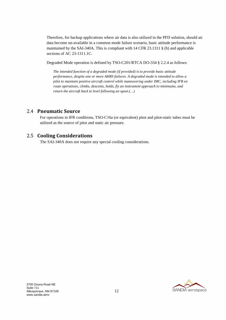
3.1 General Installation consists of securely fastening the mounting bracket to the instrument panel, constructing & connecting the power cable assembly, constructing & connecting the pneumatic lines, and mounting the unit to the bracket. Power-On is then performed, followed by unit configuration and finally unit checkout procedures.
Figure 2 – Unit Front and Rear Views
3.2 Equipment Required
3.2.1 Supplied
SAI-340A (Unit) .......................................... P/N 306171-20 SAI-340A Battery Type 0 ............................. P/N 306186 Kit, Install Electrical SAI-340 ....................... P/N 306188-00 Conn, “D” 9 Pos, Rcpt, Sldr Cup .............. P/N 305214 Clamp, D Conn Size 1 45/180 Deg ........... P/N 305207 Kit, Install Mechanical SAI-340A ................ P/N 306187-00 Bracket, Mounting Front ........................... P/N 306179 Gasket, Vibe .............................................. P/N 306505 Bracket, Mounting Rear ............................ P/N 306185 Screw, Phillips, Flat Undercut SS (X4) ..... 6-32 x 3/8 Nut, Nylon Insert, Std Zinc (X4) ............... 6-32 Hex Wrench, 3/32” L-WR Short ............... P/N 306333
3.2.2 Operational Software
SAI-340A Operation Software ...................... P/N 901099-00-EOC-V[X] (X=Latest FAA Approved Version)
3.2.3 Required, But Not Supplied
Power & Ground Wire (24 AWG, Stranded) Pitot & Static Tubing (As required)

14
3700 Osuna Road NE Suite 711 Albuquerque, NM 87109 www.sandia.aero
Pitot & Static T-Fittings (As Required)
3.3 Mounting Hole The SAI-340A is designed to mount in a standard 3” round mounting hole. The supplied front mounting bracket (P/N 306179) and rear mounting bracket (P/N 306185) must be utilized to mount the instrument. The panel cutout should be as follows:
Figure 3 - Instrument Cutout
Front and rear mounting brackets adapt the unit connection points to the 3” round instrument hole cutout. The front bracket is constructed of stainless steel, and should be inspected prior to installation to insure general flatness. The rear bracket is utilized to fasten the unit to the panel. The supplied screws and nuts must be used to retain the brackets.
3.4 Mounting Bracket Installation
1. Inspect the mounting bracket to ensure general flatness and integrity. 2. Remove any paint from REAR of instrument panel around the nut-to-panel interface points – the
mounting bracket must be fully grounded to the instrument panel. 3. Install the bracket and tighten the four screws & nuts. Ensure that the bracket is level relative to
the aircraft while the nuts are being tightened. 4. Minor roll error can be corrected by slightly rotating the bracket prior to tightening and during the
configuration of the unit.
15
3700 Osuna Road NE Suite 711 Albuquerque, NM 87109 www.sandia.aero
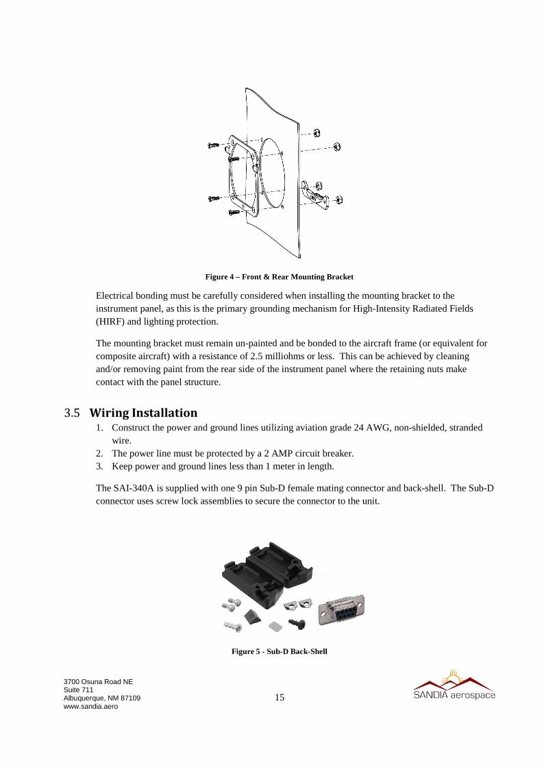
Figure 4 – Front & Rear Mounting Bracket
Electrical bonding must be carefully considered when installing the mounting bracket to the instrument panel, as this is the primary grounding mechanism for High-Intensity Radiated Fields (HIRF) and lighting protection.
The mounting bracket must remain un-painted and be bonded to the aircraft frame (or equivalent for composite aircraft) with a resistance of 2.5 milliohms or less. This can be achieved by cleaning and/or removing paint from the rear side of the instrument panel where the retaining nuts make contact with the panel structure.
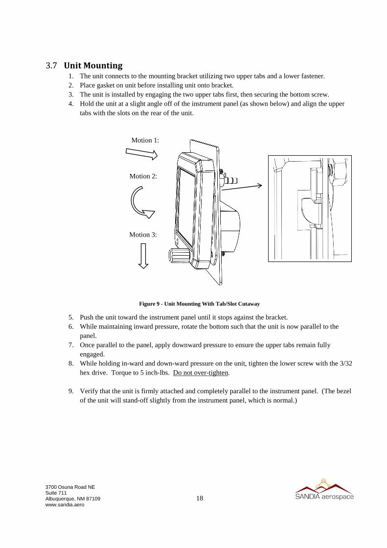
3.5 Wiring Installation 1. Construct the power and ground lines utilizing aviation grade 24 AWG, non-shielded, stranded
wire. 2. The power line must be protected by a 2 AMP circuit breaker. 3. Keep power and ground lines less than 1 meter in length.
The SAI-340A is supplied with one 9 pin Sub-D female mating connector and back-shell. The Sub-D connector uses screw lock assemblies to secure the connector to the unit.
Figure 5 - Sub-D Back-Shell

16
3700 Osuna Road NE Suite 711 Albuquerque, NM 87109 www.sandia.aero
All electrical connections are made on the single rear mounted 9 pin Sub-D. Connections indicated as Reserved - Do Not Connect (DNC) should not be connected in the installation. Power is applied to pins 5 and 9.
PIN # FUNCTION TYPE NOTES 1 Serial 1 RX Input Reserved – DNC 2 Serial 1 TX Output Garmin-G Format ADC 3 Serial 0 RX Input Reserved – DNC 4 Serial 0 TX Output Reserved – DNC 5 Power + Power Main Power Input 6 Select Input Reserved – DNC 7 V Battery Output Reserved – DNC 8 Serial Ground Signal Reserved – DNC 9 Power - Power Main Power Ground
Table 1- Electrical Pin-Out
Figure 6 - Wiring Diagram
3.6 Pneumatic Line Installation 1. Tap into the Pitot and Static lines of the aircraft with appropriate t-fittings (not supplied). 2. Construct the pneumatic lines ensuring that sufficient service loop is accounted for to allow the
unit to be easily removed from the front of the panel and access to the battery can be achieved without disconnecting the pneumatic lines.
3. Connect the Pitot line to the rear of the unit on the fitting labeled “P”. 4. Connect the Static line to the rear of the unit on the fitting labeled “S”.

17
3700 Osuna Road NE Suite 711 Albuquerque, NM 87109 www.sandia.aero
The pitot and static connections are provided by two 1/16 NPTF fittings on the rear of the unit. Also supplied are two 0.17” ID barbed fittings for optional usage.
Alternate adaptors may be required to interface to existing pitot and static lines, of which standard AN fittings should always be used. If application of thread sealant is required, “sensor safe” chemicals must be utilized.
Figure 7 – Supplied Pneumatic Fitting
When selecting alternate fittings, do not allow the threads to penetrate more than 0.3 inches into the unit, otherwise sensor damage will occur. Do not remove the foam filter located in the body of the unit.
Figure 8 – Thread Depth Limit
Foam Filter
(Do Not Remove)
Max 0.3 Inches
Insertion Depth
18
3700 Osuna Road NE Suite 711 Albuquerque, NM 87109 www.sandia.aero
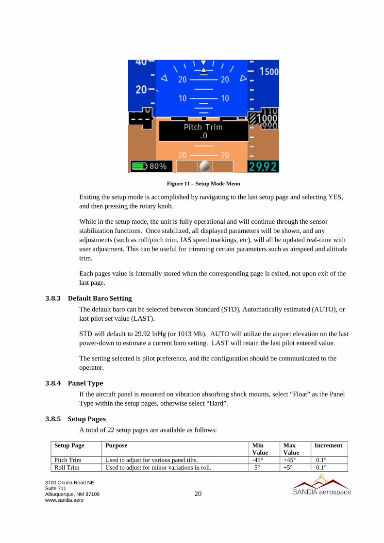
3.7 Unit Mounting 1. The unit connects to the mounting bracket utilizing two upper tabs and a lower fastener. 2. Place gasket on unit before installing unit onto bracket. 3. The unit is installed by engaging the two upper tabs first, then securing the bottom screw. 4. Hold the unit at a slight angle off of the instrument panel (as shown below) and align the upper
tabs with the slots on the rear of the unit.
Figure 9 - Unit Mounting With Tab/Slot Cutaway
5. Push the unit toward the instrument panel until it stops against the bracket. 6. While maintaining inward pressure, rotate the bottom such that the unit is now parallel to the
panel. 7. Once parallel to the panel, apply downward pressure to ensure the upper tabs remain fully
engaged. 8. While holding in-ward and down-ward pressure on the unit, tighten the lower screw with the 3/32
hex drive. Torque to 5 inch-lbs. Do not over-tighten.
9. Verify that the unit is firmly attached and completely parallel to the instrument panel. (The bezel of the unit will stand-off slightly from the instrument panel, which is normal.)
Motion 1:
Motion 3:
Motion 2:

19
3700 Osuna Road NE Suite 711 Albuquerque, NM 87109 www.sandia.aero
3.8 System Configuration The following section provides instructions for initial setup configuration of the SAI-340A. For complete operation guide, including normal and abnormal operation, see the Pilot Guide (document number 306184-00).
3.8.1 Initial Power On
Upon normal power-on, the unit will display the company logo, battery status and software version as follows:
Figure 10 - Power On Screen
If the unit does not power-on, check the following:
• Ensure power and ground connections are correct.
• Verify the breaker is in the on position and applying power to the unit.
• Verify the supply voltage is greater than 10V DC.
• Verify the integrity of all electrical connections.
• Test independent operation by removing the unit and powering from a dedicated cable and bench power source.
After displaying the splash screen for approximately 25 seconds, the unit will enter the main operating mode.
3.8.2 Entry & Exit From Setup Mode
Setup mode is enabled when the unit is powered-on while the rotary knob is being held in the pressed state. After verifying basic power-on, cycle power to the unit and enter the setup mode. Upon successful entry into the setup mode, the startup screen will be bypassed and a series of setup menus will become available. The rotary knob can then be released once the setup mode is indicated.
20
3700 Osuna Road NE Suite 711 Albuquerque, NM 87109 www.sandia.aero
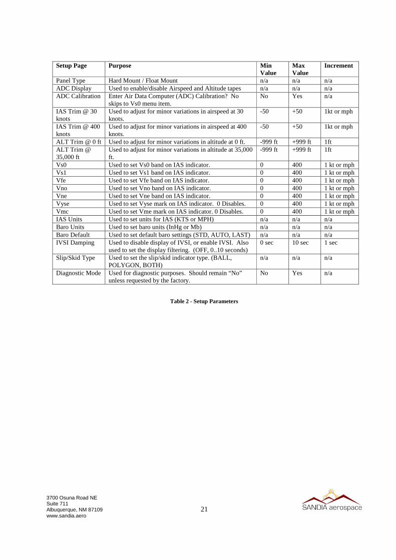
Figure 11 – Setup Mode Menu
Exiting the setup mode is accomplished by navigating to the last setup page and selecting YES, and then pressing the rotary knob.
While in the setup mode, the unit is fully operational and will continue through the sensor stabilization functions. Once stabilized, all displayed parameters will be shown, and any adjustments (such as roll/pitch trim, IAS speed markings, etc), will all be updated real-time with user adjustment. This can be useful for trimming certain parameters such as airspeed and altitude trim.
Each pages value is internally stored when the corresponding page is exited, not upon exit of the last page.
3.8.3 Default Baro Setting
The default baro can be selected between Standard (STD), Automatically estimated (AUTO), or last pilot set value (LAST).
STD will default to 29.92 InHg (or 1013 Mb). AUTO will utilize the airport elevation on the last power-down to estimate a current baro setting. LAST will retain the last pilot entered value.
The setting selected is pilot preference, and the configuration should be communicated to the operator.
3.8.4 Panel Type
If the aircraft panel is mounted on vibration absorbing shock mounts, select “Float” as the Panel Type within the setup pages, otherwise select “Hard”.
3.8.5 Setup Pages
A total of 22 setup pages are available as follows:
Setup Page Purpose Min Value
Max Value
Increment
Pitch Trim Used to adjust for various panel tilts. -45° +45° 0.1° Roll Trim Used to adjust for minor variations in roll. -5° +5° 0.1°
21
3700 Osuna Road NE Suite 711 Albuquerque, NM 87109 www.sandia.aero
Setup Page Purpose Min Value
Max Value
Increment
Panel Type Hard Mount / Float Mount n/a n/a n/a ADC Display Used to enable/disable Airspeed and Altitude tapes n/a n/a n/a ADC Calibration Enter Air Data Computer (ADC) Calibration? No
skips to Vs0 menu item. No Yes n/a
IAS Trim @ 30 knots
Used to adjust for minor variations in airspeed at 30 knots.
-50 +50 1kt or mph
IAS Trim @ 400 knots
Used to adjust for minor variations in airspeed at 400 knots.
-50 +50 1kt or mph
ALT Trim @ 0 ft Used to adjust for minor variations in altitude at 0 ft. -999 ft +999 ft 1ft ALT Trim @ 35,000 ft
Used to adjust for minor variations in altitude at 35,000 ft.
-999 ft +999 ft 1ft
Vs0 Used to set Vs0 band on IAS indicator. 0 400 1 kt or mph Vs1 Used to set Vs1 band on IAS indicator. 0 400 1 kt or mph Vfe Used to set Vfe band on IAS indicator. 0 400 1 kt or mph Vno Used to set Vno band on IAS indicator. 0 400 1 kt or mph Vne Used to set Vne band on IAS indicator. 0 400 1 kt or mph Vyse Used to set Vyse mark on IAS indicator. 0 Disables. 0 400 1 kt or mph Vmc Used to set Vme mark on IAS indicator. 0 Disables. 0 400 1 kt or mph IAS Units Used to set units for IAS (KTS or MPH) n/a n/a n/a Baro Units Used to set baro units (InHg or Mb) n/a n/a n/a Baro Default Used to set default baro settings (STD, AUTO, LAST) n/a n/a n/a IVSI Damping Used to disable display of IVSI, or enable IVSI. Also
used to set the display filtering. (OFF, 0..10 seconds) 0 sec 10 sec 1 sec
Slip/Skid Type Used to set the slip/skid indicator type. (BALL, POLYGON, BOTH)
n/a n/a n/a
Diagnostic Mode Used for diagnostic purposes. Should remain “No” unless requested by the factory.
No Yes n/a
Table 2 - Setup Parameters
22
3700 Osuna Road NE Suite 711 Albuquerque, NM 87109 www.sandia.aero
Section 4 - Instructions for Continued Airworthiness
4.1 ICA General The following Instructions for Continued Airworthiness (ICA) are to be utilized by approved mechanics. The instructions contained here-in are required to ensure proper unit functionality and performance on an on-going basis.
4.2 Airworthiness Limitations The Airworthiness Limitations section is FAA approved and specifies maintenance required under §§ 43.16 and 91.403 of the Federal Aviation Regulations unless an alternative program has been FAA approved.
4.2.1 Battery Limitations
The battery must be replaced when any of the following occurs:
• The battery fails the power-on self-test as indicated by a Red-X over the on-screen battery icon.
• The battery fails to charge during normal operation. • The battery fails the full-duration load test (described below).
• The battery pack is over 5 years old, as measured by the battery pack installation date.
4.2.2 Altimeter Limitations
The altimeter function must be tested and inspected in accordance with 14 CFR 91.411.
4.3 Battery Maintenance The SAI-340A contains a field-replaceable Li-Poly battery pack. This battery requires periodic replacement to ensure sufficient capacity is available to meet performance specifications.
4.3.1 Full-Duration Load Test
This test performs a full-discharge cycle to ensure that proper capacity is available. A degraded or aged battery will be detected by this procedure.
This procedure must be performed every 24 months.
1) This test is to be done at ambient temperature ranging from +50°F (+10°C) to +90°F (+26°C). The unit must be fully thermally stabilized in this range.
2) Ensure battery is fully charged by verifying that a charge of 100% is shown. If not, charge as follows:
a. Place the aircraft on ground-power and turn the unit on.
b. Allow the battery to fully charge to 100% and verify that the battery charging symbol is no longer presented. (Battery charging may continue for a short

23
3700 Osuna Road NE Suite 711 Albuquerque, NM 87109 www.sandia.aero
duration even though 100% is shown).
3) Set the display to full-intensity by pressing the rotary knob and rotating clockwise as needed. Press the knob again to dismiss the brightness menu.
4) Remove power to the unit by pulling the corresponding circuit breaker and cancel the power-down sequence by pressing the knob.
5) Note the current time and allow unit to operate for 2 hours. At the end of the 2 hour period, if the unit has shut-down, or on-screen parameters are Red-X’ed, the battery must be replaced.
4.3.2 Battery Replacement Procedure
The following procedure is to be used to replace the battery pack. The battery pack consists of 4 individual cells with protection and heater circuitry all enclosed in a PVC wrapping. Two sets of leads are present: 1) Heater Leads, and 2) Battery Power Leads.
Figure 12 - Li-Poly Battery Pack
Figure 13 - Li-Poly Battery Connections
Upper Heater
Connection
(Red/Red Wires)
Lower Battery
Connection
(Red/Black Wires)
Heater Leads (Red/Red)
Battery Leads (Red/Black)
! IMPORTANT !
Do not inadvertently
connect the battery to
the heater connector.
Identical connectors are
utilized for each.
Follow the indicated
color coding
DAMAGE TO THE UNIT
MAY OCCUR
Polarization Keys

24
3700 Osuna Road NE Suite 711 Albuquerque, NM 87109 www.sandia.aero
1. Only the approved batteries are to be used. See specification section of this document for the applicable Sandia part number(s).
2. Ensure power is not supplied to the unit by either pulling the applicable circuit breaker, or turning off the master switch. (Ensure the unit is not running on battery)
3. Remove the unit from the aircraft instrument panel - it is not required to disconnect the power cable or pitot/static lines unless in-adequate service loop was provided.
4. Carefully remove and retain the two Phillip’s head screws that retain the battery cover.
5. Extract the battery pack. 6. Grasp the leads in pairs and gently pull the connectors loose from the unit. Do not
pull excessively on just one individual wire. The connector is a high-friction fit connector, but does not utilize a specific un-latching mechanism.
7. Discard the old battery pack per local regulations as related to Li-Poly battery procedures.
8. Position the new battery pack such that with the tip of one finger, the connectors can be firmly pressed into place.
9. Observe the polarity lock on each connector – Note that the same connector is utilized for each function and must not be connected incorrectly.
10. Connect the longer red/red heater connector first into the upper mating connector – ensure the connector fully seats with a click.
11. Connect the shorter red/black power connector secondly into the lower mating connector – ensure the connector fully seats with a click.
12. Loop the excess wire into the cavity co-located with the battery connector. Do not run the excess wire adjacent to, over, or under the battery pack itself.
13. Insert the battery pack into the battery cavity with the label facing the battery cover. 14. Replace the battery cover, tighten the screws firmly into position. Take care to
ensure that the battery wires are fully contained within the battery compartment, and do not get pinched under the battery cover plate.
15. Re-install the unit following the procedures defined in this manual. 16. Note the date of battery replacement in the aircrafts log book. The age of the battery
is determined by the placed-in-service date, not manufacture date. 17. New battery packs will not have full charge. The battery pack should be fully
charged prior to re-entry into service.

25
3700 Osuna Road NE Suite 711 Albuquerque, NM 87109 www.sandia.aero
4.4 Airspeed and Altimeter Test & Calibration Both the airspeed and attitude sensors have the ability to be tested and calibrated in the field. Greater accuracy will be obtained by allowing the unit to fully stabilize in the on-state for a period of approximately 5 - 10 minutes prior to determining any required adjustments.
4.4.1 Altimeter System Test and Inspection
This procedure should only be performed utilizing a calibrated air-data test set. The physical connection (pitot and static) of the air-data test set is identical to that of traditional mechanical instruments. No vibration is required to be applied to the unit during testing or calibration.
The SAI-340A must be calibrated every 24 months per CFR 91.411.
4.4.2 Airspeed Trim Procedure
1. Connect the pitot-static test set to the aircraft static system. The SAI-340A must be connected to the aircraft static line.
2. Apply power to the SAI-340A while holding the pushbutton down in order to enter setup mode and allow the internal encoder to stabilize.
3. Ensure the Baro setting is 29.92 inches of mercury. (This may require disabling the AUTO Baro feature and starting this procedure from the beginning.)
4. Proceed to the “ADC Calibration?” page and choose “Yes”. Then proceed to the “IAS Trim @ 30 kts” page.
5. Configure the pitot-static test set to obtain an airspeed reading of 30 kts. 6. On the SAI-340A, adjust the trim setting until the airspeed tape reads 30 kts, then press the knob
to proceed to the “IAS Trim @ 400 kts” page. 7. Configure the pitot-static test set to obtain an airspeed reading of 400 kts. 8. On the SAI-340A, adjust the trim setting until the altitude tape reads 400 kts, then press the knob
to procede to the next setup page.
4.4.3 Altitude Trim Procedure
1. Connect the pitot-static test set to the aircraft static system. The SAI-340A must be connected to the aircraft static line.
2. Apply power to the SAI-340A while holding the pushbutton down in order to enter setup mode and allow the internal encoder to stabilize.
3. Ensure the Baro setting is 29.92 inches of mercury. (This may require disabling the AUTO Baro feature and starting this procedure from the beginning.)
4. Proceed to the “ADC Calibration?” page and choose “Yes”. Then proceed to the “ALT Trim @ 0 ft” page.
5. Configure the pitot-static test set to obtain an altimeter reading of 0 feet. 6. On the SAI-340A, adjust the trim setting until the altitude tape reads 0 feet, then press the knob to
proceed to the “ALT Trim @ 35,000 ft” page. 7. Configure the pitot-static test set to obtain an altimeter reading of 35,000 feet. 8. On the SAI-340A, adjust the trim setting until the altitude tape reads 35,000 feet, then press the
knob to procede to the next setup page.

26
3700 Osuna Road NE Suite 711 Albuquerque, NM 87109 www.sandia.aero
4.5 Troubleshooting The following information can be utilized to recognize and correct probable malfunctions.
Symptom Possible Solutions
Attitude remains Red-X’ed Ensure proper supply power is available.
Return unit for service.
Airspeed remains Red-X’ed
Ensure proper supply power is available.
Ensure airspeed limit has not been exceeded.
Return unit for service.
Altitude remains Red-X’ed
Ensure proper supply power is available.
Ensure altitude limit has not been exceeded.
Return unit for service.
Battery icon is Red-X’ed
Ensure battery is correctly installed.
Perform battery load test.
Replace battery.
Return unit for service.
Battery icon is Red-X’ed
For deeply discharged batteries, pre-charge as follows: Apply power for 10 minutes, momentarily remove power, then re-apply power. Verify charging cycle starts correctly.
On Ground, Cross-Check remains annunciated
Ensure proper supply power is available.
During power-on, ensure minimal aircraft motion is present.
Return unit for service.
Aligning message remains annunciated
Ensure proper supply power is available.
During power-on, ensure minimal aircraft motion is present.
Return unit for service.
Altitude shows error
Perform altitude trim procedure.
Return unit for service.
Airspeed shows error Perform airspeed trim procedure.
Return unit for service.
Attitude shows error Set panel tilt correctly.
Set roll trim correctly.
Return unit for service.
IVSI shows constant offset
Set panel tilt correctly.
Set roll trim correctly.
Return unit for service.
Memory Error is shown Return unit for service.
Table 3 – Troubleshooting
27
3700 Osuna Road NE Suite 711 Albuquerque, NM 87109 www.sandia.aero
[ This supplement should be reviewed and written to your applicable aircraft. A supplement like this must be inserted into the POH upon delivery ]
Section 5 - Pilot Operating Handbook This section contains an FAA approved sample Supplemental POH (Pilot Operating Handbook) for the SAI-340A. The supplement may be inserted into the POH or supplied to the airplane owner upon delivery of the system.
FAA APPROVED SUPPLEMENTAL PILOT’S OPERATING HANDBOOK
Sandia Aerospace SAI-340A
Aircraft Serial Number: ________________
Aircraft Registration Number: ________________
Aircraft Make/Model/TC Number: _________________
FAA Approved in the normal category based on CFR23. This
document must be carried in the airplane at all times.
Section 1: General This supplement to the POH provides information necessary to safely and efficiently operate the SAI-340A. The SAI-340A provides a stand-alone source of barometric attitude, indicated airspeed, altitude and slip. An integral backup battery provides continued operation if power is lost. Operation under VFR and IFR conditions are approved.
Section 2: Operational Limitations • Airspeed Limitations Markings are provided on the IAS tape. The top of the colored bands
are defined as follows: All Aircraft Over-speed Upper red band Vne Top of yellow band Vno Top of green band Vfe Top of white band Vs1 Bottom of green band Vso Bottom of white band Under-speed Lower red band Multi-Engine Aircraft Vmc Red radial mark Vyse Blue radial mark
• Maximum displayable airspeed is 400 Knots / 460 Mph
• Minimum displayable airspeed is 30 Knots / 30 Mph • Maximum displayable altitude is 35,000 Feet
28
3700 Osuna Road NE Suite 711 Albuquerque, NM 87109 www.sandia.aero
• Minimum displayable altitude is -1,500 Feet • Maximum configurable baro correction is 1067 mb / 31.50 inHg
• Minimum configurable baro correction is 931 mb / 27.50 inHg • Minimum operational duration on battery is 30 Minutes
• Maximum roll rate is 400 Degrees / Second • Maximum operating G force is 6 G
• No operational capability on internal battery is possible if the battery status indicator is faulted, as shown by a red-X over the battery icon.
Section 3: Emergency Procedures • Ensure barometric pressure is set correctly.
• While in flight and power is lost, no pilot action required to switch to internal battery or to activate backlight flight parameters. When on internal battery power, ON BATTERY is annunciated on the display.
• When operating on battery, reduction of the display intensity to lowest safe level will extend operational duration.
• Pilot initiated in-flight alignment must be performed in a wings-level non-accelerated conditions. This alignment takes less than 30 seconds and ALIGNING will be annunciated during the alignment process.
• Power-on in-flight restart must be performed in a wings-level non-accelerated conditions. This alignment takes approximately 3 minutes and ALIGNING will be annunciated during the alignment process. Excessive turbulence will cause the alignment process to take longer.
Section 4: Normal Procedures • See Sandia Aerospace SAI-340A Pilot Guide (document number 306503-00) for full normal
operating procedures. • Ensure barometric pressure is set correctly and maintained.
• Prior to departure or entry into IFR conditions, verify that the battery is not faulted (no red-X over the battery icon), and that a charge level of at least 80% is shown.
• TSO performance of airspeed, attitude, slip and attitude is met within 10 minutes during cold-starts.
• During alignment, the aircraft should not be subjected to taxing or excessive motions. • Prior to departure or entry into IFR conditions, verify that the battery has completed power-
on heating (no BAT HEATING indication shown over the battery icon). Battery operation may be inhibited for up to 15 minutes during cold-starts < 10°C.
• No autopilot, pre-select, path deviation or flight director interfaces are provided by the SAI-340A.
Section 5: Performance • No change to aircraft performance.
Section 6: Weight & Balance
• See aircraft Weight & Balance

29
3700 Osuna Road NE Suite 711 Albuquerque, NM 87109 www.sandia.aero
Section 7: System Description The SAI-340A provides stand-alone, basic airspeed, altitude, attitude and slip functions. The SAI-340A does not support integration with other avionics systems, nor does it provide complex switching interfaces with other equipment or systems. All information is displayed on a color 3.5” diagonal LCD display in traditional aerospace symbology. The unit also contains a rechargeable battery capable of providing continued operation in the event of aircraft electrical failure. While in flight and power is lost, no pilot action required to switch to internal battery or to activate backlight flight parameters. Initial Power On Upon normal power-on, the unit will display the company logo, battery status and software version as follows:
After displaying the splash screen for approximately 25 seconds, the unit will enter the main operating mode. Degraded Mode When an amber CROSS CHECK message is present the SAI-340A is considered to be in degraded mode. Degraded mode may occur if a pilot maintains an accelerated frame of reference (i.e. turns) for greater than 3 minutes. During this Degraded Mode, attitude information is always available to the pilot - it is never removed or made un-available unless failure occurs. When operating in this Degraded Mode, the SAI-340A will show on the order of ±3.0°. This condition will self-correct once the maneuver is completed. For complete operation guide, including normal and abnormal operation, see the SAI-340A Pilot Guide (document number 306503-00 or latest version).
Figure 14 - Power On Screen


![0354-0430, Augustinus, Sermones [4] de Sanctis (Serm. 273-340A), LT](https://static.fdocuments.net/doc/165x107/563db811550346aa9a9043b0/0354-0430-augustinus-sermones-4-de-sanctis-serm-273-340a-lt.jpg)