
Safety System Digital Platform -MELTAC-
355
SAFETY SYSTEM DIGITAL PLATFORM -MELTAC- MUAP-07005-NP(R8) Mitsubishi Heavy Industries, LTD. Safety System Digital Platform -MELTAC- July 2011 C 2011 Mitsubishi Heavy Industries, Ltd. All Rights Reserved Non Proprietary Version
Transcript of Safety System Digital Platform -MELTAC-
SAFETY SYSTEM DIGITAL PLATFORM -MELTAC- MUAP-07005-NP(R8)
Mitsubishi Heavy Industries, LTD.
Safety System Digital Platform -MELTAC-
July 2011
C 2011 Mitsubishi Heavy Industries, Ltd. All Rights Reserved
Non Proprietary Version
SAFETY SYSTEM DIGITAL PLATFORM -MELTAC- MUAP-07005-NP(R8)
Mitsubishi Heavy Industries, LTD.
i
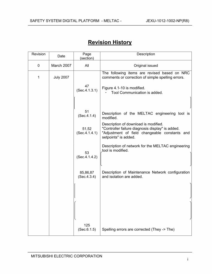
Revision History
Revision Date Page
(Section) Description
0 March 2007 All Original issued
1 July 2007 Refer to Revision History of JEXU-1012-1002-P(R1)
2 August 2008 Refer to Revision History of JEXU-1012-1002-P(R2)
3 December
2008 Refer to Revision History of JEXU-1012-1002-P(R3)
4 September
2009 Refer to Revision History of JEXU-1012-1002-P(R4)
5 April 2010 Refer to Revision History of JEXU-1012-1002-P(R5)
6 October
2010 Refer to Revision History of JEXU-1012-1002-P(R6)
7 April
2011 Refer to Revision History of JEXU-1012-1002-P(R7)
8 July 2011
Refer to Revision History of JEXU-1012-1002-P(R8)
SAFETY SYSTEM DIGITAL PLATFORM -MELTAC- MUAP-07005-NP(R8)
Mitsubishi Heavy Industries, LTD.
ii
© 2011 MITSUBISHI HEAVY INDUSTRIES, LTD.
All Rights Reserved This document has been prepared by Mitsubishi Heavy Industries, Ltd. (“MHI”) in connection with its request to the U.S. Nuclear Regulatory Commission (“NRC”) for a pre-application review of the US-APWR nuclear power plant design. No right to disclose, use or copy any of the information in this document, other than by the NRC and its contractors in support of MHI’s pre-application review of the US-APWR, is authorized without the express written permission of MHI. This document contains technology information and intellectual property relating to the US-APWR and it is delivered to the NRC on the express condition that it not be disclosed, copied or reproduced in whole or in part, or used for the benefit of anyone other than MHI without the express written permission of MHI, except as set forth in the previous paragraph. This document is protected by the laws of Japan, U.S. copyright law, international treaties and conventions, and the applicable laws of any country where it is being used.
Mitsubishi Heavy Industries, Ltd. 16-5, Konan 2-chome, Minato-ku
Tokyo 108-8215 Japan
SAFETY SYSTEM DIGITAL PLATFORM -MELTAC- MUAP-07005-NP(R8)
Mitsubishi Heavy Industries, LTD.
iii
Abstract
This topical report which is attached JEXU-1012-1002-P describes the MELTAC digital platform. MHI seeks NRC approval of this platform for application to the safety systems of the US-APWR and for replacement of current safety systems in operating plants. The MELTAC digital platform was developed by MHI and MELCO for nuclear power plants in Japan. For applications in the US, this report demonstrates conformance of the MELTAC digital platform to all applicable US Codes and Standards. These include:
Code of Federal Regulations Regulatory Guides Branch Technical Positions NUREG-Series Publications IEEE-Standards Other Industry Standards
SAFETY SYSTEM DIGITAL PLATFORM - MELTAC - JEXU-1012-1002-NP(R8)
MITSUBISHI ELECTRIC CORPORATION
Safety System Digital Platform - MELTAC -
July 2011
2011 MITSUBISHI ELECTRIC CORPORATION All Rights Reserved
C
Non-Proprietary Version
SAFETY SYSTEM DIGITAL PLATFORM - MELTAC - JEXU-1012-1002-NP(R8)
MITSUBISHI ELECTRIC CORPORATION
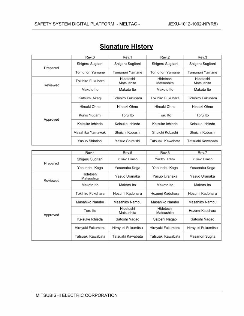
Signature History
Rev.0 Rev.1 Rev.2 Rev.3
Shigeru Sugitani Shigeru Sugitani Shigeru Sugitani Shigeru Sugitani Prepared
Tomonori Yamane Tomonori Yamane Tomonori Yamane Tomonori Yamane
Tokihiro Fukuhara Hidetoshi
Matsushita Hidetoshi
Matsushita Hidetoshi
Matsushita Reviewed
Makoto Ito Makoto Ito Makoto Ito Makoto Ito
Katsumi Akagi Tokihiro Fukuhara Tokihiro Fukuhara Tokihiro Fukuhara
Hiroaki Ohno Hiroaki Ohno Hiroaki Ohno Hiroaki Ohno
Kunio Yugami Toru Ito Toru Ito Toru Ito
Keisuke Ichieda Keisuke Ichieda Keisuke Ichieda Keisuke Ichieda
Masahiko Yamawaki Shuichi Kobashi Shuichi Kobashi Shuichi Kobashi
Approved
Yasuo Shiraishi Yasuo Shiraishi Tatsuaki Kawabata Tatsuaki Kawabata
Rev.4 Rev.5 Rev.6 Rev.7
Shigeru Sugitani Yukiko Hirano Yukiko Hirano Yukiko Hirano Prepared
Yasunobu Koga Yasunobu Koga Yasunobu Koga Yasunobu Koga
Hidetoshi Matsushita
Yasuo Uranaka Yasuo Uranaka Yasuo Uranaka Reviewed
Makoto Ito Makoto Ito Makoto Ito Makoto Ito
Tokihiro Fukuhara Hozumi Kadohara Hozumi Kadohara Hozumi Kadohara
Masahiko Nambu Masahiko Nambu Masahiko Nambu Masahiko Nambu
Toru Ito Hidetoshi
Matsushita Hidetoshi
Matsushita Hozumi Kadohara
Keisuke Ichieda Satoshi Nagao Satoshi Nagao Satoshi Nagao
Hiroyuki Fukumitsu Hiroyuki Fukumitsu Hiroyuki Fukumitsu Hiroyuki Fukumitsu
Approved
Tatsuaki Kawabata Tatsuaki Kawabata Tatsuaki Kawabata Masanori Sugita
SAFETY SYSTEM DIGITAL PLATFORM - MELTAC - JEXU-1012-1002-NP(R8)
MITSUBISHI ELECTRIC CORPORATION i
Revision History
Revision Date
Page (section)
Description
0 March 2007 All Original issued
1 July 2007 The following items are revised based on NRC comments or correction of simple spelling errors.
47
(Sec.4.1.3.1)
Figure 4.1-10 is modified. ・ Tool Communication is added.
51
(Sec.4.1.4)
Description of the MELTAC engineering tool is modified.
51,52
(Sec.4.1.4.1)
Description of download is modified. "Controller failure diagnosis display" is added. "Adjustment of field changeable constants and setpoints" is added.
53
(Sec.4.1.4.2)
Description of network for the MELTAC engineering tool is modified.
85,86,87
(Sec.4.3.4)
Description of Maintenance Network configuration and isolation are added.
125
(Sec.6.1.5)
Spelling errors are corrected (They -> The)
SAFETY SYSTEM DIGITAL PLATFORM - MELTAC - JEXU-1012-1002-NP(R8)
MITSUBISHI ELECTRIC CORPORATION ii
Revision
Date Page
(section) Description
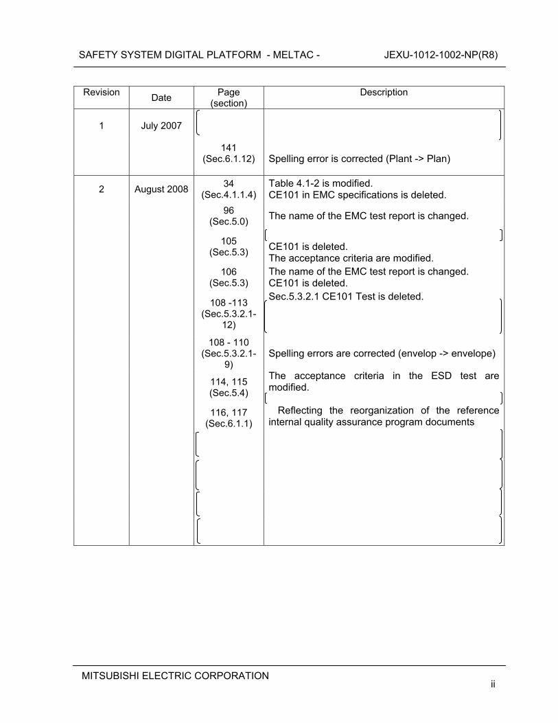
1 July 2007
141
(Sec.6.1.12)
Spelling error is corrected (Plant -> Plan)
2 August 2008 34
(Sec.4.1.1.4)Table 4.1-2 is modified. CE101 in EMC specifications is deleted.
96
(Sec.5.0) The name of the EMC test report is changed.
105
(Sec.5.3)
CE101 is deleted. The acceptance criteria are modified.
106
(Sec.5.3) The name of the EMC test report is changed. CE101 is deleted.
108 -113
(Sec.5.3.2.1-12)
Sec.5.3.2.1 CE101 Test is deleted.
108 - 110
(Sec.5.3.2.1-9)
Spelling errors are corrected (envelop -> envelope)
114, 115 (Sec.5.4)
The acceptance criteria in the ESD test are modified.
116, 117
(Sec.6.1.1) Reflecting the reorganization of the reference
internal quality assurance program documents
SAFETY SYSTEM DIGITAL PLATFORM - MELTAC - JEXU-1012-1002-NP(R8)
MITSUBISHI ELECTRIC CORPORATION iii
Revision
Date Page
(section) Description
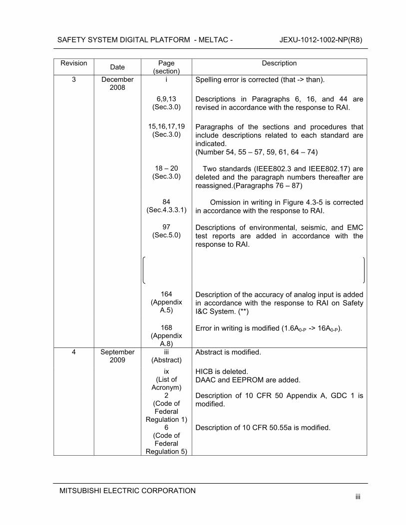
3 December 2008
i Spelling error is corrected (that -> than).
6,9,13 (Sec.3.0)
Descriptions in Paragraphs 6, 16, and 44 are revised in accordance with the response to RAI.
15,16,17,19
(Sec.3.0)
Paragraphs of the sections and procedures that include descriptions related to each standard are indicated. (Number 54, 55 – 57, 59, 61, 64 – 74)
18 – 20
(Sec.3.0)
Two standards (IEEE802.3 and IEEE802.17) are
deleted and the paragraph numbers thereafter are reassigned.(Paragraphs 76 – 87)
84
(Sec.4.3.3.1)
Omission in writing in Figure 4.3-5 is corrected
in accordance with the response to RAI.
97 (Sec.5.0)
Descriptions of environmental, seismic, and EMC test reports are added in accordance with the response to RAI.
164 (Appendix
A.5)
Description of the accuracy of analog input is added in accordance with the response to RAI on Safety I&C System. (**)
168
(Appendix A.8)
Error in writing is modified (1.6A0-P -> 16A0-P).
4 September 2009
iii (Abstract)
Abstract is modified.
ix (List of
Acronym)
HICB is deleted. DAAC and EEPROM are added.
2 (Code of Federal
Regulation 1)
Description of 10 CFR 50 Appendix A, GDC 1 is modified.
6 (Code of Federal
Regulation 5)
Description of 10 CFR 50.55a is modified.
SAFETY SYSTEM DIGITAL PLATFORM - MELTAC - JEXU-1012-1002-NP(R8)
MITSUBISHI ELECTRIC CORPORATION iv
Revision
Date Page
(section) Description
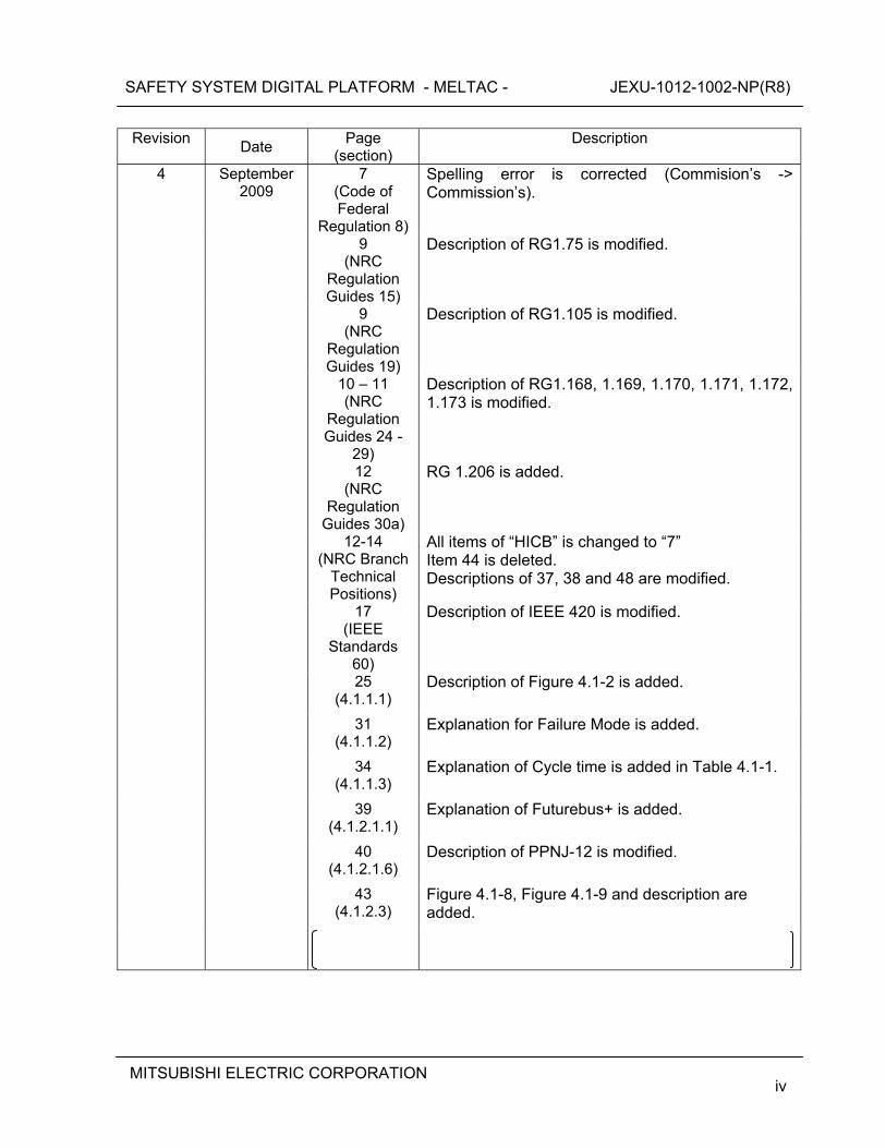
4 September 2009
7 (Code of Federal
Regulation 8)
Spelling error is corrected (Commision’s -> Commission’s).
9 (NRC
Regulation Guides 15)
Description of RG1.75 is modified.
9 (NRC
Regulation Guides 19)
Description of RG1.105 is modified.
10 – 11 (NRC
Regulation Guides 24 -
29)
Description of RG1.168, 1.169, 1.170, 1.171, 1.172, 1.173 is modified.
12 (NRC
Regulation Guides 30a)
RG 1.206 is added.
12-14 (NRC Branch
Technical Positions)
All items of “HICB” is changed to “7” Item 44 is deleted. Descriptions of 37, 38 and 48 are modified.
17 (IEEE
Standards 60)
Description of IEEE 420 is modified.
25 (4.1.1.1)
Description of Figure 4.1-2 is added.
31 (4.1.1.2)
Explanation for Failure Mode is added.
34 (4.1.1.3)
Explanation of Cycle time is added in Table 4.1-1.
39 (4.1.2.1.1)
Explanation of Futurebus+ is added.
40 (4.1.2.1.6)
Description of PPNJ-12 is modified.
43 (4.1.2.3)
Figure 4.1-8, Figure 4.1-9 and description are added.
SAFETY SYSTEM DIGITAL PLATFORM - MELTAC - JEXU-1012-1002-NP(R8)
MITSUBISHI ELECTRIC CORPORATION v
Revision
Date Page
(section) Description
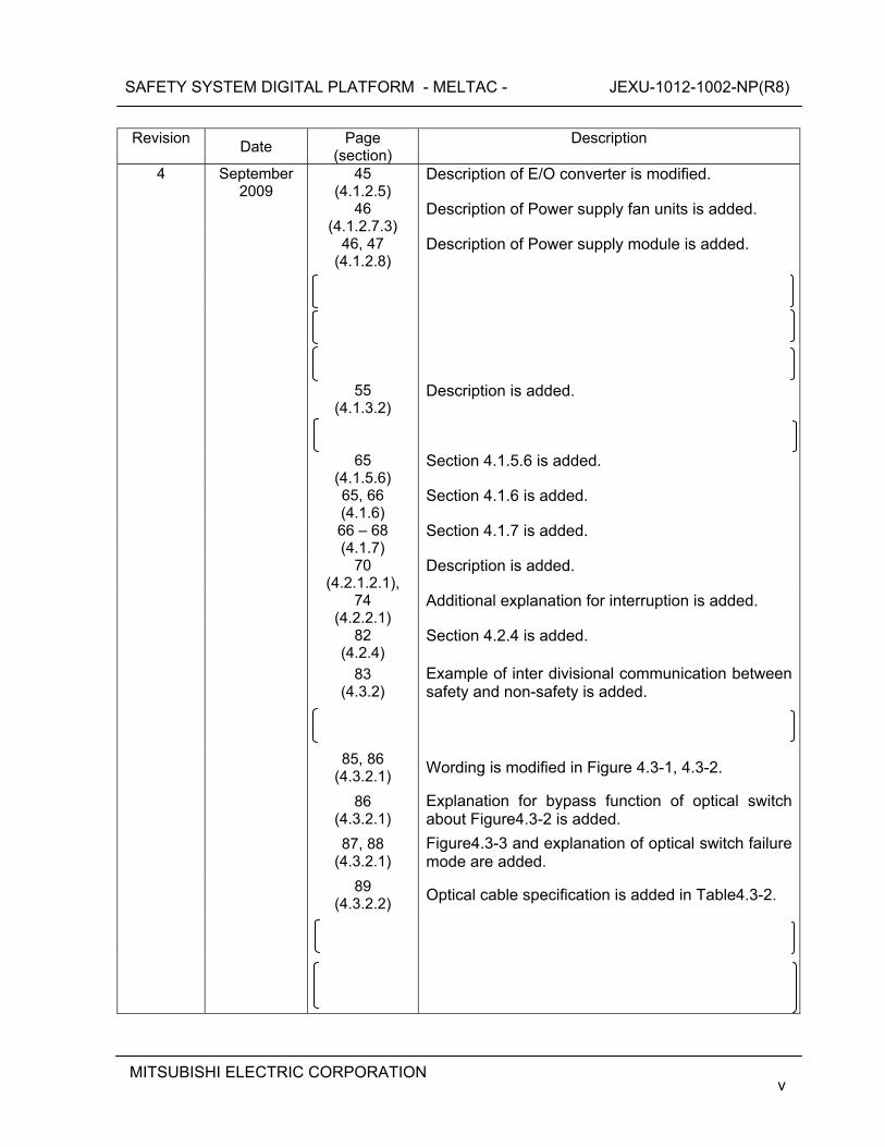
4 September 2009
45 (4.1.2.5)
Description of E/O converter is modified.
46 (4.1.2.7.3)
Description of Power supply fan units is added.
46, 47 (4.1.2.8)
Description of Power supply module is added.
55 (4.1.3.2)
Description is added.
65 (4.1.5.6)
Section 4.1.5.6 is added.
65, 66 (4.1.6)
Section 4.1.6 is added.
66 – 68 (4.1.7)
Section 4.1.7 is added.
70 (4.2.1.2.1),
Description is added.
74 (4.2.2.1)
Additional explanation for interruption is added.
82 (4.2.4)
Section 4.2.4 is added.
83
(4.3.2) Example of inter divisional communication between safety and non-safety is added.
85, 86
(4.3.2.1) Wording is modified in Figure 4.3-1, 4.3-2.
86
(4.3.2.1) Explanation for bypass function of optical switch about Figure4.3-2 is added.
87, 88
(4.3.2.1) Figure4.3-3 and explanation of optical switch failure mode are added.
89
(4.3.2.2) Optical cable specification is added in Table4.3-2.
SAFETY SYSTEM DIGITAL PLATFORM - MELTAC - JEXU-1012-1002-NP(R8)
MITSUBISHI ELECTRIC CORPORATION vi
Revision
Date Page
(section) Description
4 September 2009
102 (4.4)
Additional explanation of self-diagnosis is added.
Wording is modified. (BTP HICB-21 -> BTP 7-21)
110 (5.0)
Isolation qualification is added.
115
(5.2.2.1) Description of the configuration of the Cabinet Seismic Resistance Test specimen is added.
119
(5.2.2.2) Descriptions of the Module Seismic Resistance Test are modified.
Optical Switch and Ethernet Optical Isolation Device are added.
123
(5.3.1) The model name of safety VDU panel is changed.
SAFETY SYSTEM DIGITAL PLATFORM - MELTAC - JEXU-1012-1002-NP(R8)
MITSUBISHI ELECTRIC CORPORATION vii
Revision
Date Page
(section) Description
4 September 2009
SAFETY SYSTEM DIGITAL PLATFORM - MELTAC - JEXU-1012-1002-NP(R8)
MITSUBISHI ELECTRIC CORPORATION viii
Revision
Date Page
(section) Description
4 September 2009
156 (6.1.6.4)
Section title is modified.
SAFETY SYSTEM DIGITAL PLATFORM - MELTAC - JEXU-1012-1002-NP(R8)
MITSUBISHI ELECTRIC CORPORATION ix
Revision
Date Page
(section) Description
4 September 2009
176, 177 (7.1)
Description of “History of Operation” is modified. Table 7.1-1, the summary for history of changes of the MELTAC platform, is added.
189 (7.5)
Description for replacement cycle of Periodic replacement Parts is added.
190 (Appendix
A)
Explanation about the modules is added.
190 (Appendix
A.2)
Description of firmware is added.
191 (Appendix
A.4)
Description of firmware is added.
192, 194, 196(Appendix
A.5)
Descriptions of firmware and current consumption are added.
197 (Appendix
A.6)
Description of current consumption is added.
197 (Appendix
A.7)
Description of current consumption is added. Specification of MEOJ-11 is added.
198 (Appendix
A.8)
Description of current consumption is added.
199 (Appendix
A.10)
Description of current consumption is added.
200 (Appendix
B)
Explanation of the list is added.
SAFETY SYSTEM DIGITAL PLATFORM - MELTAC - JEXU-1012-1002-NP(R8)
MITSUBISHI ELECTRIC CORPORATION x
Revision
Date Page
(section) Description
5 April 2010 ii, 3, 4, 5, 6, 7, 8, 10, 11, 12, 13, 15, 16, 19, 20,
22, 118, 146, 154, 164, 168, 169,
170, 186, 193
Document names are modified. (Design Process Topical Report, Safety System Topical Report -> Technical Report for the US-APWR DCD)
14 (NRC Branch
Technical Positions 46)
Description of conformance to BTP 7-18 is modified.
31,32 (4.1.1.2.1)
Explanation of Mode Management is added. Description of Figure 4.1-5 is modified.
33,34 (4.1.1.2.2)
Explanation of Mode Management is added. Description of Figure 4.1-6 is modified.
59 (4.1.4.2)
Description of Network for the MELTAC engineering tool is modified.
67 (4.1.6)
Error in writing is modified. (64 -> 96)
101 (4.3.4.2)
Section 4.3.4.2, Isolation, is modified.
142 (6.1.1)
Wording is modified.
Add description about hardware procured or manufactured prior to the App. B-based QAP.
150 (6.1.4)
Wording is modified. (V&V -> independent review and test)
SAFETY SYSTEM DIGITAL PLATFORM - MELTAC - JEXU-1012-1002-NP(R8)
MITSUBISHI ELECTRIC CORPORATION xi
Revision
Date Page
(section) Description
5 April 2010
181 (6.5)
Section 6.5, MELTAC Engineering Tool Life Cycle, is added.
205 (Appendix
A.7)
Description of Ethernet Optical Isolation Module is added.
6 October 2010
14 (3.0)
“App. B- Based” is changed to "App.B-based".
22 (4.0)
“Engineering Tool” and “Maintenance Network” are deleted from the items of qualified building blocks.
22 (4.0)
The note of the Maintenance Network is added in Fig4.0-1.
35 (4.1.1.3)
Description of Input/Output in Table 4.1-1 is modified.
57,58 (4.1.4.1)
Descriptions of "b)Download" and “e)Adjustment of field changeable constants and setpoints” are modified.
59 (4.1.4.2)
Descriptions of the permanent or temporary connection of the MELTAC engineering tool and Maintenance Network are added.
86,88
(4.3.2.1) The arrows for "Optical Cable" in Fig4.3-1 and Fig4.3-2 are corrected.
87 (4.3.2.1)
Description of the key technical aspects of the Control Network is added.
101 (4.3.4.1)
Descriptions of the MELTAC engineering tool connected to the Maintenance Network are modified and added.
101 (4.3.4.1)
The note of the Maintenance Network is added in Fig4.3-8.
103 (4.3.4.2)
Figure 4.3-9 is modified.
SAFETY SYSTEM DIGITAL PLATFORM - MELTAC - JEXU-1012-1002-NP(R8)
MITSUBISHI ELECTRIC CORPORATION xii
Revision
Date Page
(section) Description
6 October 2010
104 (4.3.4.2)
Figure 4.1-10 “Dedicated Re-programming Chassis for Writing F-ROM” is added.
105 (4.3.4.2)
Descriptions of the controller connected to the Maintenance Network are modified.
106 (4.3.4.3)
The title of Section 4.3.4.3 is changed from "Design Basis of Permanent Connection" to "Design Basis of Permanent or Temporary Connection".
180 (6.3, 6.3.1)
“B Based” in the titles of Section 6.3 and Section 6.3.1 are changed to “B-based”.
7 April 2011 general All sections are revised to unify the terminology.
general Descriptions of this report are modified. Topical Report -> Technical Report
58
(4.1.4.1) Explanation of Download is added.
SAFETY SYSTEM DIGITAL PLATFORM - MELTAC - JEXU-1012-1002-NP(R8)
MITSUBISHI ELECTRIC CORPORATION xiii
Revision
Date Page
(section) Description
7 April 2011
100-114 (4.3.2.5)
Section 4.3.2.5 is added.
121-131 (4.3.3.5)
Section 4.3.3.5 is added.
132
(4.3.4.1) Description of Maintenance Network configuration is modified.
137 (4.3.4.3)
The title of Section 4.3.4.3 is changed from “Design Basis of Permanent or Temporary Connection” to “Design Basis of Connection to Maintenance Network”.
189, 194 (6.1.6)
The term "cyber security" is changed to "secure development environment ".
SAFETY SYSTEM DIGITAL PLATFORM - MELTAC - JEXU-1012-1002-NP(R8)
MITSUBISHI ELECTRIC CORPORATION xiv
Revision
Date Page
(section) Description
7 April 2011
207
(6.1.12) The terms "software safety plan/analysis" are changed to "software critical function analysis ".
216 (6.4)
The title of Section 6.4 is changed from “BTP 7-14 Assessment” to “Basic Software Program Manual”.
220 (6.5)
Description of MELTAC Engineering Tool life cycle is revised.
257
(Appendix D)Appendix D is added.
260
(Appendix E)Appendix E is added.
298
(Appendix F)Appendix F is added.
8 July 2011 xxx “ECC” is added in List of Acronyms.
1 (section 2.0)
Description on parts obsolescence is added.
10-12, 18-20(Sec.3.0)
Description of Item 22 and 24-29 are modified based on RAI 771-5827(07.01-43). Description of Item 65-67, 69-70 and 72-74 are modified based on RAI 771-5827(07.01-40).
23 (Sec.4.0)
Figure 4.0-1 is modified. Description of permanent connection between the MELTAC engineering tool and the Maintenance Network is deleted based on RAI771-5827(07.01-41).
SAFETY SYSTEM DIGITAL PLATFORM - MELTAC - JEXU-1012-1002-NP(R8)
MITSUBISHI ELECTRIC CORPORATION xv
Revision
Date Page
(section) Description
8
July 2011 39, 41, 42
(Sec. 4.1.2.1)
The name of module type and the description of module specification are changed due to parts obsolescence.
41, 42
(Sec. 4.1.2.1)Wording is modified.
43
(Sec. 4.1.2.2)Description of NIS and RMS is added.
44,46
(Sec. 4.1.2.3)Description of the Isolation Module for the RCP Pulse Input Module is added.
44
(Sec. 4.1.2.3)Figure 4.1-7 is modified with additional description of the RCP Pulse Input Module.
44,46
(Sec. 4.1.2.3)Description of the Distribution Module is added.
55
(Sec. 4.1.3.1)The strained line in the Figure 4.1-15 is corrected.
62
(Sec. 4.1.4.2)
Description of permanent connection between the MELTAC engineering tool and the Maintenance Network is deleted based on RAI771-5827(07.01-41).
65
(Sec. 4.1.5.1)Figure 4.1-17 is modified with changes in the graphic modules due to parts obsolescence.
72
(Sec. 4.1.7.1)Figure 4.1-18 is modified with changes in the graphic modules due to parts obsolescence.
73 (Sec. 4.1.7.1)
Changes in hardware and software due to parts obsolescence are reflected.
75, 77 (Sec. 4.2.1.2)
Changes in the graphic modules due to parts obsolescence are reflected.
75 (Sec. 4.2.1.2)
Description of Fire Zone is deleted.
SAFETY SYSTEM DIGITAL PLATFORM - MELTAC - JEXU-1012-1002-NP(R8)
MITSUBISHI ELECTRIC CORPORATION xvi
Revision
Date Page
(section) Description
8
July 2011 76
(Sec. 4.2.1.2)Figure 4.2-1 is modified with changes in the graphic modules due to parts obsolescence.
79
(Sec. 4.2.2.1)Figure 4.2-3 is modified with changes in the graphic modules due to parts obsolescence.
117
(Sec. 4.3.2.5)Changes in software due to parts obsolescence are reflected.
SAFETY SYSTEM DIGITAL PLATFORM - MELTAC - JEXU-1012-1002-NP(R8)
MITSUBISHI ELECTRIC CORPORATION xvii
Revision
Date Page
(section) Description
8
July 2011
130, 131, 132, 133,
(Sec.4.3.3.5)
Detail description of the CRC checking diagnosis by CPU Module basic software is added.
SAFETY SYSTEM DIGITAL PLATFORM - MELTAC - JEXU-1012-1002-NP(R8)
MITSUBISHI ELECTRIC CORPORATION xviii
Revision
Date Page
(section) Description
8
July 2011 137
(Sec. 4.3.4.1)
Description of permanent connection between the MELTAC engineering tool and the Maintenance Network is deleted based on RAI771-5827 (07.01-41).
142 (Sec. 4.3.4.2)
Description of permanent connection between the MELTAC engineering tool and the Maintenance Network is deleted based on RAI771-5827 (07.01-41).
147
(Sec. 4.4.2) Wording is modified.
SAFETY SYSTEM DIGITAL PLATFORM - MELTAC - JEXU-1012-1002-NP(R8)
MITSUBISHI ELECTRIC CORPORATION xix
Revision
Date Page
(section) Description
8
July 2011
156 (Sec. 5.0)
Description is added in accordance with parts obsolescence.
169
(Sec. 5.3.1) Description is added in accordance with parts obsolescence in Table 5.3-1.
178
(Sec. 5.5) Description is added in accordance with parts obsolescence.
228
(Sec. 7.1) Development in accordance with parts obsolescence is added in Table7.1-1.
229
(Sec. 7.2) Description is added in accordance with parts obsolescence.
239, 240
(Sec. 7.4) (Sec. 7.5)
Description is added in accordance with parts obsolescence.
243-249, 251 - 253
(Appendix A)
Modules specifications are modified in accordance with parts obsolescence.
SAFETY SYSTEM DIGITAL PLATFORM - MELTAC - JEXU-1012-1002-NP(R8)
MITSUBISHI ELECTRIC CORPORATION xx
Revision
Date Page
(section) Description
8
July 2011
245, 246, 248,249,250 (Appendix A)
IO module menu and Distribution Modules are added.
246
(Appendix A)The note of automatic testing is modified.
254-257 (Appendix A)
Appendix A.12 and Appendix A.13 are added.
261, 262 264, 265
(Appendix B)POL menu is added.
258, 259
(Appendix B)Notation of symbols is changed to NEMA format.
260, 264
(Appendix B)Notation of symbols is corrected.
268,269
(Appendix C)Procedures for App.B-based QAP in conformance to BTP-7-14 are updated.
272
(Appendix D)Description of ISG-04 is deleted.
275
(Appendix E)Description is added in accordance with parts obsolescence.
314
(Appendix F)Description of FMU Module is modified in accordance with parts obsolescence.
SAFETY SYSTEM DIGITAL PLATFORM - MELTAC - JEXU-1012-1002-NP(R8)
MITSUBISHI ELECTRIC CORPORATION xxi
© 2011 MITSUBISHI ELECTRIC CORPORATION
All Rights Reserved This document has been prepared by Mitsubishi Electric Corporation (“MELCO”) in connection with Mitsubishi Heavy Industries, LTD. (“MHI”)’s request to the U.S. Nuclear Regulatory Commission (“NRC”) for a pre-application review of the US-APWR nuclear power plant design. No right to disclose, use or copy any of the information in this document, other than by the NRC and its contractors in support of MHI’s pre-application review of the US-APWR, is authorized without the express written permission of MELCO. This document contains technology information and intellectual property relating to the MELCO’s Safety System Digital Platform (MELTAC) and it is delivered to the NRC on the express condition that it not be disclosed, copied or reproduced in whole or in part, or used for the benefit of anyone other than MELCO without the express written permission of MELCO, except as set forth in the previous paragraph. This document is protected by the laws of Japan, U.S. copyright law, international treaties and conventions, and the applicable laws of any country where it is being used.
Mitsubishi Electric Corporation 7-3, Marunouchi 2-chome, Chiyoda-ku
Tokyo 100-8310 Japan
SAFETY SYSTEM DIGITAL PLATFORM - MELTAC - JEXU-1012-1002-NP(R8)
MITSUBISHI ELECTRIC CORPORATION xxii
Abstract This Technical Report describes the design of the Mitsubishi Electric Total Advanced Controller (MELTAC) Platform and its conformance to the U.S. Nuclear Regulatory requirements for nuclear safety systems. The MELTAC platform is the basis of the Mitsubishi Heavy Industries (MHI) safety and non-safety digital I&C systems. The MELTAC platform was developed specifically for nuclear applications. The modular structure, deterministic response time and testability can be applied to solve plant-wide needs for safety and non-safety applications. Moreover the MELTAC platform has been developed using a rigorous safety-related design process that ensures suitable hardware and software quality and reliability for critical applications such as the reactor protection system or engineered safety features actuation system. The MELTAC platform has accumulated many years of positive performance records in various non-safety system applications such as the Plant Control and Monitoring System in nuclear plants operating in Japan. Based on its excellent performance in numerous non-safety applications, the MELTAC platform has now been applied to almost all systems throughout Japanese PWR nuclear plants under construction. These systems were shipped to the site recently.
The goal of this report is to seek approval from the U.S. Nuclear Regulatory Commission (NRC) for the use of the MELTAC platform for nuclear safety systems in new reactors (US-APWR).
For applications in the US, this report demonstrates conformance of the Design and Design Process to all applicable US Codes and Standards. These include: ・ Code of Federal Regulations ・ Regulatory Guides ・ Branch Technical Positions ・ NUREG-Series Publications ・ IEEE-Standards ・ Other Industry Standards The information provided in this report covers the following topics to fully understand the MELTAC platform: ・ The design of the hardware, software, communication network and application
development tools of the MELTAC platform ・ The equipment qualification of the MELTAC platform and its conformance to the
corresponding U.S. standards ・ The life cycle and the Quality Assurance Program of the MELTAC platform conformed to
U.S. regulations ・ The history of operation and the equipment reliabilities of the MELTAC platform
The complete MHI digital I&C design is described in Topical Reports and a Technical Report for the US-APWR DCD: ・ Safety I&C System Description and Design Process (Technical Report for the US-APWR
DCD) ・ Safety System Digital Platform - MELTAC - (this report)
SAFETY SYSTEM DIGITAL PLATFORM - MELTAC - JEXU-1012-1002-NP(R8)
MITSUBISHI ELECTRIC CORPORATION xxiii
・ HSI System Description and HFE (Human Factor Engineering) Process ・ Defense in Depth and Diversity The information in this Digital Platform Technical Reports is expected to be sufficient to allow the NRC to make a final safety determination regarding the suitability of the MELTAC platform for safety-related nuclear applications, on the condition of completing specific application engineering as identified in the other topical reports. Other documentation which has been generated during the MELTAC design process is available for NRC audit, as may be needed to allow the NRC to confirm the MELCO design and design process, as documented in this Technical Report.
SAFETY SYSTEM DIGITAL PLATFORM - MELTAC - JEXU-1012-1002-NP(R8)
MITSUBISHI ELECTRIC CORPORATION xxiv
Table of Contents
List of Tables......................................................................................................................... xxvii List of Figures........................................................................................................................xxviii List of Acronyms...................................................................................................................... xxx 1.0 PURPOSE............................................................................................................................ 1 2.0 SCOPE................................................................................................................................. 1 3.0 APPLICABLE CODE, STANDARDS AND REGULATORY GUIDANCE ............................. 2 4.0 MELTAC PLATFORM DESCRIPTION............................................................................... 23
4.1 Controller ........................................................................................................................ 24 4.1.1 Hardware Configuration ........................................................................................... 24 4.1.2 Hardware Descriptions............................................................................................. 39 4.1.3 Software................................................................................................................... 55 4.1.4 MELTAC Engineering Tool ...................................................................................... 60 4.1.5 Self-Diagnosis.......................................................................................................... 63 4.1.6 Bus inside the controller........................................................................................... 70 4.1.7 Manual test .............................................................................................................. 71
4.2 Safety VDU Panel and Processor................................................................................... 74 4.2.1 Hardware ................................................................................................................. 74 4.2.2 Software .................................................................................................................. 79 4.2.3 Self-Diagnosis.......................................................................................................... 86 4.2.4 Manual test .............................................................................................................. 87
4.3 Communication System.................................................................................................. 88 4.3.1 General Description ................................................................................................. 88 4.3.2 Control Network ....................................................................................................... 88 4.3.3 Data Link................................................................................................................ 119 4.3.4 Maintenance Network ............................................................................................ 137
4.4 Response Time ........................................................................................................... 146 4.4.1 Processing Time of MELTAC Fundamental Cycle................................................. 146 4.4.2 Processing Time of MELTAC Application .............................................................. 147 4.4.3 Examples of Response Time Calculations............................................................. 151
4.5 Control of Access ......................................................................................................... 153 4.5.1 Control of Access for Hardware ............................................................................. 153 4.5.2 Control of Access for Software............................................................................... 153
4.6 Elimination or Relaxation of Surveillance ..................................................................... 154
5.0 ENVIRONMENTAL, SEISMIC, ELECTROMAGNETIC AND ISOLATION QUALIFICATION .... 156
5.1 Environmental Test....................................................................................................... 156 5.1.1 Environmental Specification and Outline of Test ................................................... 156 5.1.2 Contents of Environmental Test............................................................................. 156
5.2 Seismic Test ................................................................................................................ 161 5.2.1 Overview ................................................................................................................ 161 5.2.2 Seismic Resistance Test........................................................................................ 161
5.3 Electromagnetic Compatibility and Radio Frequency Interference............................... 167 5.3.1 Test Configuration.................................................................................................. 168 5.3.2 Description of Tests ............................................................................................... 170
5.4 Electrostatic Discharge Test ......................................................................................... 176
SAFETY SYSTEM DIGITAL PLATFORM - MELTAC - JEXU-1012-1002-NP(R8)
MITSUBISHI ELECTRIC CORPORATION xxv
5.5 Isolation Test ................................................................................................................ 178 6.0 LIFE CYCLE .................................................................................................................... 182
6.1 Life Cycle Process........................................................................................................ 184 6.1.1 Overview of the MELTAC Quality Assurance Program.......................................... 184 6.1.2 Quality Assurance Program Rev 2......................................................................... 187 6.1.3 Management .......................................................................................................... 189 6.1.4 Development .......................................................................................................... 190 6.1.5 Configuration Management.................................................................................... 195 6.1.6 Secure Development Environment Management .................................................. 198 6.1.7 US Conformance Program for Previously Developed Components ...................... 203 6.1.8 Software Installation............................................................................................... 208 6.1.9 Maintenance .......................................................................................................... 211 6.1.10 Training ................................................................................................................ 212 6.1.11 Operations ........................................................................................................... 213 6.1.12 Software Critical Function Analysis...................................................................... 216
6.2 Life Cycle Management ................................................................................................ 218 6.2.1 Quality Records Management................................................................................ 218 6.2.2 Failure and Error Reporting and Corrective Action ................................................ 218 6.2.3 Obsolescence Management .................................................................................. 220 6.2.4 Identification........................................................................................................... 221 6.2.5 Reliability Database ............................................................................................... 222
6.3 Establishment of 10 CFR Part 50 Appendix B-based QA Program, and MELTAC Re-evaluation Program......................................................................................................... 223 6.3.1 Establishment of 10 CFR Part 50 Appendix B-based QA Program ....................... 223 6.3.2 MELTAC Re-evaluation Program........................................................................... 225
6.4 Basic Software Program Manual .................................................................................. 225 6.5 MELTAC Engineering Tool Life Cycle .......................................................................... 226
7.0 EQUIPMENT RELIABILITY.............................................................................................. 227 7.1 History of Operation...................................................................................................... 227 7.2 Mean Time between Failures (MTBF) Analysis............................................................ 229 7.3 Controller Reliability Analysis ....................................................................................... 232
7.3.1 Reliability Model ..................................................................................................... 233 7.3.2 FTA for Spurious Actuation of the Safety Function ................................................ 234 7.3.3 FTA of Failure to Actuate the Safety Function ....................................................... 235 7.3.4 Detailed Controller Reliability Analysis................................................................... 236
7.4 Failure Mode and Effects Analysis (FMEA) .................................................................. 239 7.5 Periodic Replacement Equipment (Parts) to Keep Reliability....................................... 240 7.6 Performance history of self-diagnosis function ............................................................. 241
APPENDIX A HARDWARE SPECIFICATIONS..................................................................... 243 Appendix A.1 CPU Module Specification............................................................................ 243 Appendix A.2 System Management Module Specification ................................................. 243 Appendix A.3 Bus Master Module Specification ................................................................. 244 Appendix A.4 Control Network I/F Module Specification .................................................... 244 Appendix A.5 I/O Module Specification .............................................................................. 245 Appendix A.6 Isolation Module and Distribution Module Specifications ............................. 249 Appendix A.7 E/O Converter Modules Specifications......................................................... 251 Appendix A.8 Power Interface Modules Specifications ...................................................... 252 Appendix A.9 Power Supply Modules Specifications ......................................................... 252 Appendix A.10 Safety VDU Panel Specification................................................................. 253 Appendix A.11 FMU Module Specification ......................................................................... 253 Appendix A.12 NIS ............................................................................................................. 254
SAFETY SYSTEM DIGITAL PLATFORM - MELTAC - JEXU-1012-1002-NP(R8)
MITSUBISHI ELECTRIC CORPORATION xxvi
Appendix A.13 RMS Module Specification ......................................................................... 257 APPENDIX B FUNCTIONAL SYMBOL SOFTWARE SPECIFICATIONS ............................. 258 APPENDIX C CONFORMANCE TO BTP 7-14...................................................................... 267 APPENDIX D CONFORMANCE MAP OF ISG-04 CHAPTER 1............................................ 272 APPENDIX E SOFTWARE CRITICAL FUNCTION ANALYSIS............................................. 275 APPENDIX F DEFINITION..................................................................................................... 313
SAFETY SYSTEM DIGITAL PLATFORM - MELTAC - JEXU-1012-1002-NP(R8)
MITSUBISHI ELECTRIC CORPORATION xxvii
List of Tables Table 4.1-1 Scale and Capacity ............................................................................................... 36 Table 4.1-2 Environmental Specifications ................................................................................ 37 Table 4.1-3 Module in the CPU Chassis .................................................................................. 39 Table 4.1-4 CPU Chassis......................................................................................................... 40 Table 4.1-5 Cabinet of MELTAC Platform Specifications......................................................... 51 Table 4.1-6 Bus inside the controller........................................................................................ 71 Table 4.1-7 I/O bus specification.............................................................................................. 71 Table 4.2-1 Explanation of the Screen..................................................................................... 82 Table 4.2-2 Data Details .......................................................................................................... 84 Table 4.3-1 Configuration of Control Network .......................................................................... 89 Table 4.3-2 The Specification of Control Network.................................................................... 95 Table 4.3-3 Self-Diagnosis Functions of Control Network...................................................... 101 Table 4.3-4 The Specification of Data Link Communication .................................................. 121 Table 4.3-5 The Specification of Maintenance Network Communication............................... 144 Table 4.4-1 Description of Processing in Each Component (maximum/minimum values)..... 149 Table 5.3-1 MELTAC Modules for the EMC Test................................................................... 169 Table 6.1-1 QA Procedures ................................................................................................... 185 Table 6.1-2 Contents of Activity in Each Phase ..................................................................... 192 Table 6.1-3 Contents of Hardware Development Activity in Each Phase .............................. 194 Table 6.1-4 Security Measures of the Software Development/Storage Environment ............ 200 Table 6.1-5 Security Measures in the Software Development Process ................................. 201 Table 6.1-6 Information Provided in the MELTAC Maintenance Manual ............................... 211 Table 6.1-7 Hardware Measurement...................................................................................... 213 Table 6.1-8 Software Upgrades Relation ............................................................................... 215 Table 6.1-9 Possible Hazards ................................................................................................ 217 Table 6.3-1 Relationship Between App.B-based QAP and Previous QAP ............................ 224 Table 7.1-1 The summary for history of changes of the MELTAC platform ........................... 228 Table 7.2-1 Failure rate of modules ....................................................................................... 230 Table 7.5-1 List of Periodic Replacement Parts ..................................................................... 241 Table 7.6-1 Number of failures............................................................................................... 242
SAFETY SYSTEM DIGITAL PLATFORM - MELTAC - JEXU-1012-1002-NP(R8)
MITSUBISHI ELECTRIC CORPORATION xxviii
List of Figures Figure 4.0-1 Typical Configuration of MELTAC Platform ......................................................... 23 Figure 4.1-1 Single Controller Configuration ............................................................................ 25 Figure 4.1-2 Redundant Parallel Controller Configuration ....................................................... 27 Figure 4.1-3 Redundant Standby Controller Configuration ...................................................... 29 Figure 4.1-4 Picture of Modules in a CPU Chassis for a Redundant Standby Controller Configuration............................................................................................................................ 30 Figure 4.1-5 Mode Management of Single Controller and Redundant Parallel........................ 32 Figure 4.1-6 Mode Management of Redundant Standby Controller......................................... 34 Figure 4.1-7 Location of Isolation Modules .............................................................................. 44 Figure 4.1-8 The Internal Configuration Diagram of The Analog Isolation Modules ................ 45 Figure 4.1-9 The Internal Configuration Diagram of The Digital Isolation Module ................... 45 Figure 4.1-10 The Internal Configuration Diagram of The Pulse Input Isolation Module ......... 46 Figure 4.1-11 The Internal Configuration Diagram of The PIF Module .................................... 48 Figure 4.1-12 Cabinet External Dimensions and Rack Up, Typical Sample A......................... 52 Figure 4.1-13 Cabinet External Dimensions and Rack Up, Typical Sample B......................... 53 Figure 4.1-14 Configuration of Power Supply for Controller Cabinet ....................................... 54 Figure 4.1-15 Basic Software Processes and Execution Order ............................................... 55 Figure 4.1-16 Remaining Time Diagnosis ................................................................................ 58 Figure 4.1-17 Coverage of Self-diagnosis function of the controller ........................................ 65 Figure 4.1-18 Manual test for process input and output........................................................... 72 Figure 4.2-1 Configuration of Safety VDU Processor............................................................... 76 Figure 4.2-2 Configuration of Power Supply for Safety VDU ................................................... 78 Figure 4.2-3 Software Structure of Safety VDU Processor ..................................................... 79 Figure 4.2-4 Screen Transition of the Safety VDU Processor.................................................. 81 Figure 4.2-5 A Sample of Operation Switch Pictogram on the Safety VDU Panel................... 83 Figure 4.2-6 Explanation of the Safety VDU Processor Operation .......................................... 85 Figure 4.3-1 Configuration of Control Network ........................................................................ 90 Figure 4.3-2 Explanation of Bypass Operation by the Optical Switch ...................................... 92 Figure 4.3-3 Explanation of Optical Switch Failure .................................................................. 93 Figure 4.3-4 Protocol Stack of Control Network ....................................................................... 95 Figure 4.3-5 Separation in Communication of Control Network ............................................. 100 Figure 4.3-6 Operation signal flow from O-VDU .................................................................... 103 Figure 4.3-7 Process signal flow from RPS to Unit Bus ......................................................... 104 Figure 4.3-8 Detail signal flow in COM (Receiving process) .................................................. 105 Figure 4.3-9 Detail signal flow in RPS (Sending process)...................................................... 106 Figure 4.3-10 Processing by the Control Network I/F Module................................................ 108 Figure 4.3-11 Processing by the CPU Module ...................................................................... 110 Figure 4.3-12 Processing by the CPU Module ....................................................................... 113 Figure 4.3-13 Processing by the Control Network I/F Module................................................ 115 Figure 4.3-14 Example of Connection Configuration of Data Link Configuration................... 119 Figure 4.3-15 Separation in Communication of Data Link...................................................... 124 Figure 4.3-16 Partial Trip signal flow between RPSs ............................................................. 126 Figure 4.3-17 Detail signal flow in RPS (Receiving process) ................................................. 127 Figure 4.3-18 Detail signal flow in RPS (Sending process).................................................... 128 Figure 4.3-19 Processing by the Bus Master Module ............................................................ 129 Figure 4.3-20 Processing by the CPU Module ....................................................................... 130
SAFETY SYSTEM DIGITAL PLATFORM - MELTAC - JEXU-1012-1002-NP(R8)
MITSUBISHI ELECTRIC CORPORATION xxix
Figure 4.3-21 Processing by the CPU Module ....................................................................... 132 Figure 4.3-22 Processing by the Bus Master Module ............................................................ 134 Figure 4.3-23 Maintenance Network Configuration................................................................ 137 Figure 4.3-24 Separation in Communication of Maintenance Network .................................. 140 Figure 4.3-25 Dedicated Re-programming Chassis for Writing F-ROM................................. 141 Figure 4.4-1 The Time Chart of Fundamental Process in Cyclic............................................ 146 Figure 4.4-2 Internal Process Divisions of the MELTAC Platform to Perform Response Time Calculations............................................................................................................................ 148 Figure 5.5-1 Isolation Test Configuration of KILJ-01 for Transverse Mode Faults................. 179 Figure 5.5-2 Isolation Test Configuration of KILJ-01 for Common Mode Faults .................... 179 Figure 5.5-3 Isolation Test Configuration of KIDJ-01 for Transverse Mode Faults ................ 180 Figure 5.5-4 Isolation Test Configuration of KIDJ-01 for Common Mode Faults.................... 180 Figure 6.1-1 Outline of In-house QA Procedures System and Relationship of Various Plans ..187 Figure 6.1-2 Outline of Software Development Plan .............................................................. 191 Figure 6.1-3 Outline of Problem Tracking/Resolution Process .............................................. 193 Figure 6.1-4 Security Measures of the Software Development/Storage Environment ........... 199 Figure 6.1-5 Software Installation........................................................................................... 210 Figure 7.1-1 MELTAC Development and Operating History .................................................. 228 Figure 7.3-1 Reliability Model................................................................................................. 233 Figure 7.3-2 Fault Tree for Output Failure Spurious Actuation .............................................. 234 Figure 7.3-3 Fault Tree for Failure to Actuate ........................................................................ 235 Figure 7.3-4 Reliability Model of Subsystem.......................................................................... 236 Figure 7.3-5 Fault Tree of Subsystem.................................................................................... 236 Figure 7.3-6 Reliability Model of Dedicated I/O...................................................................... 237 Figure 7.3-7 Fault Tree of Dedicated I/O................................................................................ 237 Figure 7.3-8 Input/Output Line .............................................................................................. 238 Figure 7.3-9 Fault Tree of Input/Output Line.......................................................................... 238 Figure 7.5-1 Failure Rate Curve............................................................................................. 240
SAFETY SYSTEM DIGITAL PLATFORM - MELTAC - JEXU-1012-1002-NP(R8)
MITSUBISHI ELECTRIC CORPORATION xxx
List of Acronyms
AI Analog Input ANSI American National Standards Institute AO Analog Output ASME American Society of Mechanical Engineers ATWS Anticipated Transient without Scram BTP Branch Technical Position CEAS MELCO Corporate Electronic Archive System CFR Code of Federal Regulations COTS Commercial Off The Shelf CPU Central Processing Unit CRC Cyclic Redundancy Check CSMA/CD Carrier Sense Multiple Access with Collision Detection DAAC Diverse Automatic Actuation Cabinet DAC Design Acceptance Criteria DAS Diverse Actuation System DBA Design Basis Accident DI Digital Input DO Digital Output DSP Digital Signal Processor ECC Error Correcting Code EEPROM Electronically Erasable Programmable Read Only Memory EMC Electromagnetic Compatibility EMI Electromagnetic Interference ESC Energy Systems Center in Mitsubishi Electric Corporation ESD Electrostatic Discharge ESFAS Engineered Safety Features Actuation System EUT Equipment under Test E/O Electrical / Optical FBD Functional Block Diagram FMEA Failure Mode and Effect Analysis FMU Frame Memory Unit F-ROM Flash Electrically Erasable Programmable Read Only Memory GBD Graphic Block Diagram GDC General Design Criteria GUI Graphic User Interface HSI Human System Interface ID Identification IEC International Electrotechnical Commission IEEE Institute of Electrical and Electronics Engineers IPL Interposing Logic ISO International Standardization Organization IT Information Technology ITAAC Inspection, Test, Analysis, and Acceptance Criteria I/O Input/Output I&C Instrumentation and Control JEC Japanese Electrotechnical Committee
SAFETY SYSTEM DIGITAL PLATFORM - MELTAC - JEXU-1012-1002-NP(R8)
MITSUBISHI ELECTRIC CORPORATION xxxi
JIS Japanese Industrial Standards JEAG Japanese Electric Association Guide JEIDA Japan Electronic Industry Development Association LCO Limiting Conditions for Operation LED Light Emitting Diode MCB Main Control Board MCR Main Control Room MELENS Mitsubishi Electric Total Advanced Controller Engineering Station MELCO Mitsubishi Electric Corporation MELTAC Mitsubishi Electric Total Advanced Controller METI Ministry of Economy, Trade and Industry MHI Mitsubishi Heavy Industries, Ltd. MTBF Mean Time Between Failures MTTR Mean Time To Repair NC Normally Close NO Normally Open NPD Nuclear Power Department in Mitsubishi Electric Corporation NRC Nuclear Regulatory Commission OBE Operational Basis Earthquakes PIF Power Interface QA Quality Assurance QAP Quality Assurance Program QC Quality Control RAM Random Access Memory RFI Radio Frequency Interference RG Regulatory Guide RGB Red/Green/Blue ROM Read Only Memory RPR Resilient Packet Ring RPS Reactor Protection System RTD Resistance Temperature Detector RTM Requirements Traceability Matrix SSE Safe Shutdown Earthquake VDU Visual Display Unit V&V Verification and Validation UCP MELTAC US Conformance Program UDP/IP User Datagram Protocol Internet Protocol UV-ROM Ultra-Violet Erasable Programmable Read Only Memory UTP Unshielded Twist Pair Cable WDT Watchdog Timer
SAFETY SYSTEM DIGITAL PLATFORM - MELTAC - JEXU-1012-1002-NP(R8)
MITSUBISHI ELECTRIC CORPORATION
1
1.0 PURPOSE The purpose of this report is to describe a nuclear safety Platform by Mitsubishi Electric Corporation. One common platform with a modular structure can be applied to solve most utility needs for safety applications, including new systems, component replacements and complete system replacements. The platform is referred to as Mitsubishi Electric Total Advanced Controller Platform; or simply as “MELTAC platform “. The MELTAC platform is applied to the protection and safety monitoring system, which includes the reactor protection system, engineered safety feature actuation system, safety logic system, safety-related HSI system, and any other safety system. In addition, the MELTAC platform is applied to non-safety systems such as the Plant Control and Monitoring System. The MELTAC equipment applied for non-safety applications is the same design as the equipment for safety applications. However, there are differences in Quality Assurance methods for software design and other software life cycle processes. The goal of this report is to seek approval from the U.S. Nuclear Regulatory Commission for the use of the MELTAC platform for nuclear safety systems in new reactors. 2.0 SCOPE The scope of this report includes the hardware and software associated with the MELTAC platform. The MELTAC platform described herein encompasses design, qualification, and reliability. Model numbers in this report represent current numbers at the time of this document revision. Model numbers will change as the product life cycle progresses. New models will retain the minimum functional features, performance specifications and reliability of current models. The MELTAC platform will be used for the safety systems of new plants (US-APWR).
SAFETY SYSTEM DIGITAL PLATFORM - MELTAC - JEXU-1012-1002-NP(R8)
MITSUBISHI ELECTRIC CORPORATION
2
3.0 APPLICABLE CODE, STANDARDS AND REGULATORY GUIDANCE
This section identifies conformance to applicable codes and standards. Unless specifically noted, the latest version issued on the date of this document is applicable. The following terminology is used in this section:
Plant Licensing Documentation – This refers to plant level documentation that is specific to a group of plants or a single plant, such as the Design Certification Document, Combined Operating Licensing Application, Final Safety Analysis Report, or License Amendment Request. Equipment - This refers to the components that are the subject of this Technical Report. “Equipment” includes the MHI safety-related digital I&C systems and the MELCO safety-related digital I&C platform. “Equipment” does not include the MHI non-safety digital I&C or HSI systems nor the MELCO non-safety digital I&C or HSI platforms. It is noted that the MHI non-safety digital I&C systems utilize the MELCO non-safety digital I&C platform which is the same as the MELCO safety-related digital I&C platform. However, some QA aspects of design and manufacturing are not equivalent between safety and non-safety systems/platforms.
Code of Federal Regulations
1. 10 CFR 50 Appendix A: General Design Criteria for Nuclear Power Plants
GDC 1: Quality Standards and Records The MELCO quality program that meets all requirements of 10CFR50 Appendix B is described in Section 6. This is referred to as the App.B-based QAP. This program governs the re-evaluation of MELTAC development activities conducted under previous MELCO quality programs that used the requirements of 10CFR50 Appendix B as a guideline, but were not in full compliance with 10CFR50 Appendix B. The re-evaluation demonstrates that MELTAC has suitable technical characteristics and quality for nuclear safety applications, and is therefore equivalent to a product developed under a 10CFR50 Appendix B quality program.
GDC 2: Design Bases For Protection Against Natural Phenomena This Equipment is seismically qualified. The Equipment is located within building structures that provide protection against other natural phenomena. Specific buildings and Equipment locations are described in Plant Licensing Documentation. GDC 4: Environmental And Dynamic Effects Design Bases This Equipment is located in a mild environment that is not adversely effected by plant accidents. GDC 5: Sharing of Structures, Systems, and Components In general, there is no sharing of this Equipment among nuclear power units. Any sharing is discussed in specific Plant Licensing Documentation.
GDC 12: Suppression Of Reactor Power Oscillations
SAFETY SYSTEM DIGITAL PLATFORM - MELTAC - JEXU-1012-1002-NP(R8)
MITSUBISHI ELECTRIC CORPORATION
3
Specific reactor trip functions implemented within this Equipment are described in Plant Licensing Documentation.
GDC 13: Instrumentation And Control Specific instrumentation and control functions implemented within this Equipment are described in Plant Licensing Documentation.
GDC 17: Electric Power Systems The electric power sources for this Equipment and the plant components controlled by this Equipment are discussed in Plant Licensing Documentation. This document describes the interface requirements for these power sources.
GDC 19: Control Room This Equipment provides safety-related Human System Interfaces (HSI) for the control room. The MHI non-safety digital I&C systems and the MELCO non-safety digital I&C platform provide non-safety HSI for the control room. The Human Factors design aspects of the HSI and the control room design are described in other digital system licensing documentation.
GDC 20: Protection System Functions Specific protection system functions implemented within this Equipment are described in Plant Licensing Documentation.
GDC 21: Protection System Reliability and Testability This Equipment includes automated testing with a high degree of coverage, and additional overlapping manual test features for the areas that are not covered by automated tests. Most manual tests may be conducted with the plant on line, and with the Equipment bypassed or out of service. Equipment that cannot be tested with the plant on line can be tested with the plant shutdown. Depending on the system design for a specific plant, the Equipment is configured with N or N+1 redundancy, where N is the number of divisions needed for single failure compliance and to meet the plant reliability goals. For systems with N+1 redundancy, this GDC is met with one division continuously bypassed or out of service. The redundancy configuration for each plant system is described in other digital system licensing documentation.
GDC 22: Protection System Independence Redundant divisions are physically and electrically isolated to ensure that failures that originate in one division cannot propagate to other divisions. Physical isolation is discussed in the Safety I&C System Description and Design Process Technical Report for the US-APWR DCD and Plant Licensing Documentation. Platform features to accommodate electrical isolation are discussed in this Technical Report. All Equipment is qualified to ensure that the Equipment is unaffected by adverse conditions that may concurrently effect multiple divisions. The qualification limits of this equipment are described in this Technical Report. The Safety I&C System Description and Design Process Technical Report for the US-APWR DCD describes the analysis methods used to demonstrate conformance to those limits
SAFETY SYSTEM DIGITAL PLATFORM - MELTAC - JEXU-1012-1002-NP(R8)
MITSUBISHI ELECTRIC CORPORATION
4
for actual plant conditions. Plant Licensing Documentation describes the specific analysis for each plant. Interlocks between redundant divisions and administrative controls ensure maintenance is performed on one division at a time. Interlocks are described in the Safety I&C System Description and Design Process Technical Report for the US-APWR DCD. Administrative controls are described in Plant Licensing Documentation.
GDC 23: Protection System Failure Modes Signals are generated for all detected failures. These signals can be configured at the application level to generate alarms. Functions can be designed to fail to an actuated trip state on loss of all power, on failures that are not automatically detected, or on failures that are automatically detected and would prevent proper execution of the function. Functions can also be designed to fail to an unactuated state. The unactuated state may be desirable to avoid spurious plant transients. Compliance for reactor trip and ESFAS functions are described in the Safety I&C System Description and Design Process Technical Report for the US-APWR DCD.
GDC 24: Separation of Protection and Control Systems
Redundant divisions of the protection systems are physically and electrically isolated from the non-safety control systems. Where safety sensors are shared between control and protection systems, signal selection logic in the control system prevents erroneous control actions due to single sensor failures. Eliminating these erroneous control actions prevents challenges to the protection system while it is degraded due to the same sensor failure. Where non-safety signals control safety systems or components, logic in the safety systems ensures prioritization of safety functions.
GDC 25: Protection System Requirements For Reactivity Control Malfunctions Specific functions implemented within this Equipment to protect against Reactivity Control Malfunctions are described in Plant Licensing Documentation. Specific features designed into the MHI non-safety control systems to limit the extent of Reactivity Control Malfunctions is described in Plant Licensing Documentation.
GDC 29: Protection Against Anticipated Operation Occurrences The Equipment achieves an extremely high probability of accomplishing its safety functions through components with conservative design margins, redundancy to accommodate random failures, a quality program that minimizes the potential for design or manufacturing errors.
2. 10CFR50.34 (f)(2) Post-TMI Requirements
(iii) Control room
The Human Factors design aspects of the HSI and the control room are described in the HSI Topical Report and other digital system plant licensing documentation.
SAFETY SYSTEM DIGITAL PLATFORM - MELTAC - JEXU-1012-1002-NP(R8)
MITSUBISHI ELECTRIC CORPORATION
5
(iv) Safety Parameter Display
The non-safety HSI systems provide safety parameter displays in the control room. Some data presented on safety parameter displays originates in this Equipment.
(v) Bypassed and inoperable status indication
This indication is provided by this Equipment and by the non-safety HSI system. All bypassed or inoperable signals for safety systems originate in this Equipment.
(xi) Relief and safety valve position Indication
(xii) Auxiliary feedwater system initiation and flow indication
(xiii) Pressurizer heater control
(xiv) Containment isolation systems
(xvii) Accident monitoring instrumentation
(xviii) Inadequate core cooling monitoring
(xix) Instruments for monitoring plant conditions following core damage
(xx) Pressurizer level indication and controls for pressurizer relief and block valves
Specific functions implemented within this Equipment to meet the Post-TMI requirements, items xi thru xx above, are described in Plant Licensing Documentation.
3. 10 CFR 50.36 Technical specifications
1) Safety limits, limiting safety system settings, and limiting control settings.
This Equipment is used in digital safety systems to maintain safety limits. The MELCO non-safety digital I&C platform is used in non-safety control systems to maintain control limits.
2) Limiting conditions for operation. This Equipment can be configured at the application level with N or N+1 redundancy, as discussed above for conformance to GDC 21. The Limiting Conditions for Operation (LCO) related to bypassed or out of service conditions for a single division are dependent upon the extent of redundancy. The Safety I&C System Description and Design Process Technical Report for the US-APWR DCD describes the LCO for this Equipment. 3) Surveillance requirements This Equipment includes extensive self-diagnostic testing, as discussed above for conformance to GDC 21. Provisions are included for periodic surveillances to confirm the operability of the self-diagnostic test features. Provisions can also be included at that application level to manually test features of the system that are not tested automatically. The test interval for all manual tests is based, in part, on
SAFETY SYSTEM DIGITAL PLATFORM - MELTAC - JEXU-1012-1002-NP(R8)
MITSUBISHI ELECTRIC CORPORATION
6
Equipment reliability which is described in Section 7.3 of this report. Specific manual surveillance features are described in the Safety I&C System Description and Design Process Technical Report for the US-APWR DCD.
4. 10 CFR 50.49 Environmental Qualification Of Electric Equipment Important To Safety For Nuclear Power Plants
This Equipment is located in a mild environment. A mild environment is an environment that would at no time be significantly more severe than the environment that would occur during normal plant operation, including anticipated operational occurrences. Therefore this criteria is not applicable. This criteria is applicable to some instrumentation that interfaces to this Equipment. The qualification of this instrumentation is described in Plant Licensing Documentation.
5. 10 CFR 50.55a (a)(1) Quality Standards for Systems Important to Safety This Equipment was originally developed under a Japanese nuclear quality program that encompasses most requirements of 10CFR50 Appendix B. Section 6 describes the App.B-based QAP, which is fully compliant to 10CFR50 Appendix B. The App.B-based QAP governs the re-evaluation of previous MELTAC development, and all new MELTAC development or revisions that may occur after this re-evaluation.
(h) Invokes IEEE Std. 603-1991
See conformance to IEEE 603-1991
6. 10 CFR 50.62 ATWS Rule
The Diverse Actuation System (DAS), which is used to actuate plant systems for ATWS mitigation, is described briefly in the Safety I&C System Description and Design Process Technical Report for the US-APWR DCD, MUAP-07004, and in more depth in the Defense in Depth and Diversity Topical Report, MUAP-07006. The DAS is diverse from this Equipment for all reactor trip functions. The DAS and the safety logic system, described in MUAP-07004, utilize a common output module that interfaces to plant components. This common module is described in all Topical Reports as the Power Interface (PIF) module. To ensure compliance with the ATWS rule, the PIF module is not used for any reactor trip functions. The diversity between MELTAC and the DAS is described in the Defense in Depth and Diversity Topical Report.
7. 10 CFR 52.47
(a)(1)(iv) Resolution of Unresolved and Generic Safety Issues
(a)(1)(vi) ITAAC in Design Certification Applications
(a)(1)(vii) Interface Requirements
Conformance to the requirements in items iv thru vii, above, are described in Plant Licensing Documentation .
(a)(2) Level of Detail
SAFETY SYSTEM DIGITAL PLATFORM - MELTAC - JEXU-1012-1002-NP(R8)
MITSUBISHI ELECTRIC CORPORATION
7
The content of this Technical Report, together with the additional information described in other digital system Topical Reports and Plant Licensing Documentation, is sufficient to allow the NRC staff to reach a final conclusion on all safety questions associated with the design. The information includes performance requirements and design information sufficiently detailed to permit the preparation of acceptance and inspection requirements by the NRC, and procurement specifications and construction and installation specifications by an applicant.
(b)(2)(i) Innovative Means of Accomplishing Safety Functions
In the near term, the Equipment is expected to be applied to conventional I&C safety and non-safety functions typical of new evolutionary plants. In the longer term, the Equipment is expected to be applied to more innovative safety functions as may be typical of new passive plants. All specific plant safety functions are described in Plant Licensing Documentation.
8. 10 CFR 52.79(c) ITAAC in Combined Operating License Applications
The inspections, tests, analyses and acceptance criteria that demonstrate that this Equipment has been constructed and will operate in conformity with the Commission’s final safety conclusion, will be described in the Plant Licensing Documentation.
Staff Requirements Memoranda
9. SRM to SECY 93-087
II.Q Defense Against Common-Mode Failures in Digital I&C Systems Conformance is described in the Defense-in-Depth and Diversity Topical Report.
II.T Control Room Annunciator (Alarm) Reliability This Equipment and the MHI non-safety I&C systems can be configured at the application level to generate alarms. Alarm annunciators are provided by the MHI non-safety HSI system. Conformance to requirements for redundancy, and conformance to separation and independence criteria between safety divisions and between safety and non-safety divisions is described in the Safety I&C System Description and Design Process Technical Report for the US-APWR DCD.
NRC Regulatory Guides
10. RG 1.22 Periodic Testing of Protection System Actuation Functions See GDC 21 conformance. The functions controlled by this Equipment can be configured at the application level to be completely testable through a combination of overlapping automatic and manual tests. The detail is described in the Safety I&C System Description and Design Process Technical Report for the US-APWR DCD.
SAFETY SYSTEM DIGITAL PLATFORM - MELTAC - JEXU-1012-1002-NP(R8)
MITSUBISHI ELECTRIC CORPORATION
8
11. RG 1.29 Revision 03 Seismic Design Classification
The Equipment is designated Seismic Category I.
12. RG 1.47 Bypassed and Inoperable Status Indication for Nuclear Power Plant Safety Systems
See conformance to 10CFR50.34 (f)(2)(v). The Equipment can be configured at the application level so that alarms are provided for all bypassed or inoperable safety functions. The ability to manually actuate bypassed or inoperable alarms can also be configured for conditions that are not automatically detected. The detail is described in the Safety I&C System Description and Design Process Technical Report for the US-APWR DCD.
13. RG 1.53 Application of the Single-Failure Criterion to Nuclear Power Plant Protection Systems
endorses IEEE Std 379-2000
See conformance to GDC 21 and 24. This Equipment can be configured at the application level so that safety functions are designed with N or N+1 divisions. Each safety division can be independent from the other safety divisions and from non-safety divisions. Independence ensures that credible single failures cannot propagate between divisions within the system and therefore can not prevent proper protective action at the system level. Single failures considered in the divisions are described in the Failure Modes and Effects Analyses (FMEA) for each system. The FMEA method for the components of this Equipment is provided in this Technical Report. The FMEA method for specific plant applications is described in the Safety I&C System Description and Design Process Technical Report for the US-APWR DCD. The actual plant specific FMEA is described in Plant Licensing Documentation.
14. RG 1.62 Manual Initiation of Protective Actions The Equipment can be configured at the application level so that all RPS and ESFAS safety functions can be manually initiated at the system level by conventional switches located in the main control room. Additional system level manual initiation switches may also be located at the Remote Shutdown panel, depending on the specific plant design; these are described in Plant Licensing Documentation . The Equipment can be configured at the application level so that manual initiation requires a minimum of Equipment, the Equipment common to manual and automatic initiation paths is kept to a minimum and no credible single failure in the manual, automatic or common portions will prevent initiation of a protective action by manual or automatic means. Manual initiation is described in the Safety I&C System Description and Design Process Technical Report for the US-APWR DCD.
15. RG 1.75 Physical Independence of Electric Systems
endorses IEEE 384-1992
Redundant safety divisions are physically and electrically independent of each other and physically and electrically independent of any non-safety divisions.
SAFETY SYSTEM DIGITAL PLATFORM - MELTAC - JEXU-1012-1002-NP(R8)
MITSUBISHI ELECTRIC CORPORATION
9
Physical independence is maintained either by the required distance or by barriers which prevent propagation of fire or electrical faults. Electrical independence is maintained by fiber optic cable communication interfaces or conventional isolators, such as opto-couplers, relays or transformers. Conventional isolators include fault interrupting devices such as fuses or circuit breakers. Conventional isolators prevent propagation of transverse and common mode faults from the maximum credible energy source. Fiber optic cable communication interfaces are described in Section 4.3.2.3 (Control Network), 4.3.3.2 (Data Link) and 4.3.4.2 (Maintenance Network). Specifications and qualification of conventional isolators are discussed in Section 4.1.2.3 and 5.5 of this Technical Report, respectively.
16. RG 1.89 Qualification for Class 1E Equipment for Nuclear Power Plants
endorses IEEE323-1974 The environmental qualification of this Equipment is by an appropriate combination of type testing and analysis. This Equipment is located in a mild environment that is not adversely effected by plant accidents. Therefore qualification for radiation is by analysis of component specifications. Qualification for temperature and humidity is by type test, and by analysis of room ambient conditions and heat rise calculations for the installed configuration. Seismic qualification and EMI qualification are by type testing. This Equipment has no known aging mechanisms, except as noted in Section 7.5; random failures will be detected through self-diagnostics and periodic surveillance testing. Type testing for conformance to RG 1.89 is described through the aggregate of all qualification reports – Environmental, Seismic and EMC, see section 5.
17. RG 1.97 Instrumentation for Light Water Cooled Nuclear Power Plants to Assess Plant Conditions During and Following an Accident
endorses IEEE Std. 497-2002 This Equipment is used to process and display signals from accident monitoring instrumentation of all variable Types. It meets all the applicable requirements. Signals from some accident monitoring instrumentation are also transmitted from this Equipment to the non-safety HSI system for displays and alarms. Independence is maintained between all divisions. Specific accident monitoring instrumentation is described in Plant Licensing Documentation .
18. RG 1.100 Seismic Qualification of Electric and Mechanical Equipment for Nuclear Power Plants
This Equipment is designated Seismic Category I. It is designed and qualified to withstand the cumulative effects of a minimum of five (5) Operational Basis Earthquakes (OBEs) and one (1) Safe Shutdown Earthquake (SSE) without loss of safety function or physical integrity. The input spectrum is selected to envelope all anticipated applications. Conformance to this envelope for specific applications is discussed in Plant Licensing Documentation .
SAFETY SYSTEM DIGITAL PLATFORM - MELTAC - JEXU-1012-1002-NP(R8)
MITSUBISHI ELECTRIC CORPORATION
10
19. RG 1.105 Setpoints for Safety-Related Instrumentation
endorses ISA-S67.04-1994 and ANS-10.4-1987
The uncertainties associated with the Equipment are described in this Technical Report. Appendix A.5 defines I/O module accuracies. Appendix A.6 defines isolation module accuracies. Appendix A.9 defines accuracy of I/O power supplies. This includes uncertainties for signal conditioning modules, signal splitters, instrument loop power suppliers and analog to digital converters. The uncertainties associated with specific process instrumentation and the resulting safety-related setpoints are described in Plant Licensing Documentation. The methodology used to combine all uncertainties to establish safety-related setpoints is described in the Safety I&C System Description and Design Process Technical Report for the US-APWR DCD. The plant specific uncertainty/setpoint analysis is described in Plant Licensing Documentation.
20. RG 1.118 Periodic Testing of Electric Power and Protection Systems
endorses IEEE 338-1987
See conformance to GDC 21, 10CFR50.36 and RG 1.22. The Equipment can be configured so that all safety functions are tested either automatically or manually, and so that manual tests do not require any system reconfiguration, such as jumpers or fuse removal. The periodic test features are described in the Safety I&C System Description and Design Process Technical Report for the US-APWR DCD.
21. RG 1.151 Instrument Sensing Lines
endorses ISA-S67.02
Compliance is described in Plant Licensing Documentation .
22. RG 1.152 Criteria for Programmable Digital Computers in Safety Systems of Nuclear Power Plants
endorses IEEE 7-4.3.2-2003 The methods used for specifying, designing, verifying, validating and maintaining software for this Equipment conforms to these requirements. The life cycle process for the original MELTAC digital platform software, that was developed in Japan and has been commercially dedicated for safety applications (see Item 46), is described in this Technical Report. The life cycle process for the current MELTAC platform is described in the MELTAC Platform Basic Software Program Manual (JEXU-1012-1132). The life cycle process for the system application software is described in US-APWR Software Program Manual (MUAP-07017). The methods used for ensuring a secure development and operational environment throughout the life cycle are described in these documents.
23. RG 1.153 1996 Criteria for Safety Systems
endorses IEEE Std 603-1991 Compliance with the General Design Criterion identified in this Regulatory Guide is discussed above. Compliance with IEEE 603-1991 is discussed below.
SAFETY SYSTEM DIGITAL PLATFORM - MELTAC - JEXU-1012-1002-NP(R8)
MITSUBISHI ELECTRIC CORPORATION
11
24. RG 1.168 Verification, Validation, Reviews, and Audits for Digital Computer Software Used in Safety Systems of Nuclear Power Plants
endorses IEEE Std 1012-1998 and IEEE Std 1028-1997
This Equipment uses processes for verification, validation, reviews and audits that conform to this Regulatory Guide. The software life cycle design processes for the original MELTAC digital platform, that was developed in Japan and has been commercially dedicated for safety applications (see Item 46), are described in Section 6 of this Technical Report. The software life cycle design processes for the current MELTAC platform is described in the MELTAC Platform Basic Software Program Manual (JEXU-1012-1132). Section 6 of this Technical Report includes references to the corresponding original MELTAC software life cycle procedures. Appendix C of this Technical Report provides a complete list of MELTAC software life cycle procedures with a cross correlation to the guidance of BTP 7-14. The software life cycle design processes for plant systems are described in US-APWR Software Program Manual (MUAP-07017).
25. RG 1.169 Configuration Management Plans for Digital Computer Software Used in Safety Systems of Nuclear Power Plants
endorses IEEE Std 828-1990 and IEEE Std 1042-1987
This Equipment is designed and maintained using a Configuration Management process that conforms to this Regulatory Guide. The Configuration Management process for the original MELTAC digital platform, that was developed in Japan and has been commercially dedicated for safety applications (see Item 46), is described in Section 6.1.5 of this Technical Report. The Configuration Management process for the current MELTAC platform is described in the MELTAC Platform Basic Software Program Manual (JEXU-1012-1132). The Configuration Management process for plant systems is described in US-APWR Software Program Manual (MUAP-07017).
26. RG 1.170 Software Test Documentation for Digital Computer Software Used in Safety Systems of Nuclear Power Plants
endorses IEEE Std 829-1983
The test documentation for this Equipment conforms to this Regulatory Guide. The test process and corresponding documentation for the original MELTAC digital platform, that was developed in Japan and has been commercially dedicated for safety applications (see Item 46), are described in Section 6.1.4 of this Technical Report. The test process and corresponding documentation for the current MELTAC platform are described in the MELTAC Platform Basic Software Program Manual (JEXU-1012-1132). The test documentation for plant systems is described in US-APWR Software Program Manual (MUAP-07017).
27. RG 1.171 Software Unit Testing for Digital Computer Software Used in Safety Systems of Nuclear Power Plants
endorses IEEE Std 1008-1987
Unit testing for this Equipment conforms to this Regulatory Guide. This unit testing for the original MELTAC digital platform, that was developed in Japan and has been commercially dedicated for safety applications(see Item 46), is
SAFETY SYSTEM DIGITAL PLATFORM - MELTAC - JEXU-1012-1002-NP(R8)
MITSUBISHI ELECTRIC CORPORATION
12
described in Section 6.1.4 of this Technical Report. The unit testing for the current MELTAC platform is described in the MELTAC Platform Basic Software Program Manual (JEXU-1012-1132). Unit testing for plant systems is described in US-APWR Software Program Manual (MUAP-07017).
28. RG 1.172 Software Requirements Specifications for Digital Computer Software Used in Safety Systems of Nuclear Power Plants
endorses IEEE Std 830-1993
The Software Requirements Specifications for this Equipment conforms to this Regulatory Guide. The Software Requirements Specifications for the original MELTAC digital platform, that was developed in Japan and has been commercially dedicated for safety applications (see Item 46), are described in Section 6.1.4 of this Technical Report. The Software Requirements Specifications for the current MELTAC platform are described in the MELTAC Platform Basic Software Program Manual (JEXU-1012-1132). The Software Requirements Specifications for plant systems are described in US-APWR Software Program Manual (MUAP-07017).
29. RG 1.173 Developing Software Life Cycle Processes for Digital Computer Software Used in Safety Systems of Nuclear Power Plants
endorses IEEE Std 1074-1995
The Software Life Cycle Process for this Equipment conforms to this Regulatory Guide. The Software Life Cycle Processes for the original MELTAC digital platform, that was developed in Japan and has been commercially dedicated for safety applications (see Item 46), are described in Section 6 of this Technical Report. The Software Life Cycle Processes for the current MELTAC platform are described in the MELTAC Platform Basic Software Program Manual (JEXU-1012-1132). The Software Life Cycle Processes for plant systems is described in US-APWR Software Program Manual (MUAP-07017).
30. RG 1.180 Guidelines for Evaluating Electromagnetic and Radio-Frequency Interference in safety-related Instrumentation and Control Systems
endorses MIL-STD-461E, IEC 61000 Parts 3, 4, and 6, IEEE Std C62.41-1991, IEEE Std C62.45-1992, IEEE Std 1050-1996, EPRI TR-102323
This Equipment conforms to the EMI/RFI requirements of this standard. Qualification testing for the digital platform is described in this Technical Report. Requirements and features of plant systems that ensure conformance to the platform qualification envelope are described in the Safety I&C System Description and Design Process Technical Report for the US-APWR DCD .
30.a RG1.206 Combined License Applications for Nuclear Power Plants (LWR Edition)
The level of detail provided in this report conforms to this Regulatory Guide and is expected to be sufficient for the NRC staff to make a final safety determination regarding the suitability of the MELTAC platform for safety-related applications. This document is intended to supplement the information
SAFETY SYSTEM DIGITAL PLATFORM - MELTAC - JEXU-1012-1002-NP(R8)
MITSUBISHI ELECTRIC CORPORATION
13
provided in COL applications. This document may be referenced directly or indirectly (via reference to a certified design, which references this document). Should the NRC Safety Evaluation Report for this Technical Report identify Application Specific Action Items, those open items will be addressed within an ITAAC for the certified design.
NRC Branch Technical Positions
31. BTP 7-1 Guidance on Isolation of Low-Pressure Systems from the High-Pressure Reactor Coolant System
32. BTP 7-2 Guidance on Requirements of Motor-Operated Valves in the Emergency Core Cooling System Accumulator lines
33. BTP 7-3 Guidance on Protection System Trip Point Changes for Operation with Reactor Coolant Pumps out of Service
34. BTP 7-4 Guidance on Design Criteria for Auxiliary Feedwater Systems
35. BTP 7-5 Guidance on Spurious Withdrawals of Single Control Rods in Pressurized Water Reactors
36. BTP 7-6 Guidance on Design of Instrumentation and Controls Provided to Accomplish Changeover from Injection to Recirculation Mode
Compliance with BTP 7-1 thru 6, above, is described in Plant Licensing Documentation.
37. BTP 7-8 Guidance for Application of Regulatory Guide 1.22
The Equipment includes extensive self-diagnostics which run continuously. The Equipment can be configured at the application level with additional manual test features to test the portions of the system that are not tested automatically. These manual test features can be configured so that all functions of the protection system are testable at power. Self-diagnostics are described in Section 4.1.5 of this Technical Report. Manual test features are described in Section 4.1.7 and 4.2.4 of this Technical Report, and also in the Safety I&C System Description and Design Process Technical Report for the US-APWR DCD.
38. BTP 7-9 Guidance on Requirements for Reactor Protection System Anticipatory Trips
In general there are no non-safety anticipatory trips used in the protection system. Any exception to this will be described in Plant Licensing Documentation. If any non-safety trips are used in the protection system the following requirements are met:
SAFETY SYSTEM DIGITAL PLATFORM - MELTAC - JEXU-1012-1002-NP(R8)
MITSUBISHI ELECTRIC CORPORATION
14
All non-safety equipment can be isolated from the safety system to prevent electrical fault propagation and adverse communication interaction.
Safety functions have priority over all non-safety functions.
Analysis demonstrates that credible non-safety signal failures do not result in plant conditions that are outside the boundary of the safety analysis.
39. BTP 7-10 Guidance on Application of Regulatory Guide 1.97
The Equipment conforms to this BTP for processing all instrumentation signals. However, RG 1.97 Revision 4 has superseded Revisions 2 and 3, for which this BTP was written. Therefore, where there are conflicts, the Equipment meets the requirements of RG 1.97 Revision 4.
40. BTP 7-11 Guidance on Application and Qualifications of Isolation Devices
endorses IEEE Std 472, ANSI Std C62.36, ANSI Std C62.41, ANSI Std C62.45
See conformance to RG 1.75. Isolation devices are qualified in conformance to these standards.
41. BTP 7-12 Guidance on Establishing and Maintaining Instrument Setpoints
See conformance to RG 1.105.
42. BTP 7-13 Guidance on Cross-Calibration of Protection System Resistance Temperature Detectors The methods used for periodically verifying the accuracy and response time of RTDs conforms to this standard. The method is described in Plant Licensing Documentation.
43. BTP 7-14 Guidance on SW Reviews for Digital Computer-Based I&C Systems
endorses IEEE Std 730
See conformance to RG 1.168 thru 1.173.
44. Deleted.
45. BTP 7-17 Guidance on Self-Test and Surveillance Test Provisions See conformance to GDC 21, 10CFR50.36, RG 1.22 and RG 1.118. Surveillance testing taken together with automatic self-testing provides a mechanism for detecting all failures.
46. BTP 7-18 Guidance on Use of Programmable Logic Controllers in Digital Computer-Based I&C Systems
SAFETY SYSTEM DIGITAL PLATFORM - MELTAC - JEXU-1012-1002-NP(R8)
MITSUBISHI ELECTRIC CORPORATION
15
This Equipment is not a commercial-grade computer system; it was designed originally for nuclear safety applications in Japan. Since it has been deployed in numerous non-safety nuclear applications in Japan and will be deployed in nuclear safety applications in Japan in the near future. All of this operating experience in Japan is directly applicable to expected nuclear safety applications in the US. However, since the Japanese QA program to which MELTAC was designed, does not directly comply with 10CFR50 Appendix B, a description of the MELTAC Re-evaluation Program (MRP) is provided in Section 6.3. The MRP demonstrates that the design life cycle activities for MELTAC, including supplemental conformance activities, have resulted in a design that is equivalent to a design resulting from a 10CFR50 Appendix B program. The MRP is a non-recurring activity applicable only to the MELTAC design life cycle, prior to US applications. All future MELTAC life cycle activities, including hardware and software design, manufacturing, testing, operations, maintenance and retirement, will be conducted under MELCO’s App.B-based QAP.
47. BTP 7-19 Guidance on Evaluation of Defense-in-Depth and Diversity in Digital Computer-Based I&C Systems The MHI safety-related digital I&C systems utilize the MELCO safety-related digital I&C platform (ie. this Equipment). The MHI non-safety digital I&C systems utilize the MELCO non-safety digital I&C platform. The two MELCO platforms are essentially the same, however some QA aspects of design and manufacturing are not equivalent between safety and non-safety platforms. The Defense-in-Depth and Diversity Topical Report describes the functional diversity within the safety and non-safety I&C systems. The report also describes the methodology for coping with a common cause failure of all of these systems and provides and example of this methodology for one Design Basis Accident (DBA). Coping for all Design Basis Accidents (DBAs) is described in Plant Licensing Documentation.
48. BTP 7-21 Guidance on Digital Computer Real-Time Performance
The real-time performance for this Equipment conforms to this BTP. The method for determining response time performance for plant systems (including the digital platform) is described in the Safety I&C System Description and Design Process Technical Report for the US-APWR DCD. The response time performance for digital platform components is described in Section 4.4 of this Technical Report. Requirements for system response time for conformance with the plant design basis and the response time of actual plant systems is described in Plant Licensing Documentation.
NUREG-Series Publications (NRC Reports)
49. NUREG-0737, Supplement 1 Clarification of TMI Action Plan Requirements
This Equipment can be configured at the application level for conformance to the following TMI Action Plan Requirements:
SAFETY SYSTEM DIGITAL PLATFORM - MELTAC - JEXU-1012-1002-NP(R8)
MITSUBISHI ELECTRIC CORPORATION
16
Plant Safety Parameter Display – This Equipment can provide safety-related data to the MHI non-safety HSI system which can provide this display for the control room and for emergency support facilities.
Indication and Control for Safety Components (eg. relief valves, pressurizer heaters, containment isolation valves), Inadequate Core Cooling Monitoring and Instrumentation for Accident Monitoring - This Equipment can provide safety-related controls and monitoring for safety-related instruments to generate safety-related displays. Alarms and non-safety displays can be generated by the MHI non-safety HSI system.
These features are described in the Safety I&C System Description and Design Process Technical Report for the US-APWR DCD.
50. NUREG-0800 Chapter 7 of the USNRC Standard Review Plan for the Review of Safety Analysis Reports for Nuclear Power Plants, Rev 4
This Equipment fulfills all safety-related requirements of this NUREG for monitoring safety-related plant instrumentation and controlling safety-related plant components. Descriptions of specific plant systems are described in Plant Licensing Documentation.
51. NUREG/CR-6303 Method for Performing Diversity and Defense-in-Depth Analyses of Reactor Protection Systems
The design of this Equipment is described in this Technical Report. The assessment of diversity within this Equipment and between this Equipment and other I&C systems is described in the Diversity and Defense-in-Depth Topical Report. The Diversity and Defense-in-Depth Topical Report also describes the method of coping with common mode failure vulnerabilities.
52. NUREG/CR-6421 A Proposed Acceptance Process For Commercial-Off-The-Shelf (COTS) Software in Reactor Applications This NUREG is not applicable to this Equipment since there is no COTS software. All software has been designed for nuclear applications.
IEEE Standards
53. IEEE 7-4.3.2 2003 Criteria for Programmable Digital Computer Systems in Safety Systems of Nuclear Power Generating Stations
This Equipment conforms to all requirements of this standard, as augmented by RG 1.152, including key requirements for:
Software quality and life cycle processes
Independent Verification and Validation
Communications independence Conformance is described in Sections 4 through 6.
54. IEEE 323 2003 Qualifying Class 1E Equipment for Nuclear Power Generating Systems
SAFETY SYSTEM DIGITAL PLATFORM - MELTAC - JEXU-1012-1002-NP(R8)
MITSUBISHI ELECTRIC CORPORATION
17
This Equipment is qualified in conformance to this standard, as augmented by RG 1.89. See conformance to RG1.89.
55. IEEE 338 1987 Periodic Surveillance Testing of Nuclear Power Generating Station Safety Systems
The self-diagnostics that are credited for Periodic Surveillance Testing are described throughout this document. As described in RG 1.22 item 10, RG1.22 and IEEE338 test features that are configured at the system level or within the application software are not described in this Technical Report but in ”Safety I&C System Description and Design Process Technical Report for the US-APWR DCD”.
56. IEEE 344 1987 Seismic Qualification of Class 1E Equipment for Nuclear Power Generating Stations
This Equipment conforms to this standard as augmented by RG 1.100. Conformance is described in the Seismic Qualification Report.
57. IEEE 379 2000 Application of the Single-Failure Criterion to Nuclear Power Generating Station Safety Systems As described in RG1.53 item 13, compliance to the Single-Failure Criterion is achieved through the configuration of this Equipment at the system level. The system configuration for nuclear safety applications is provided in MUAP-07004.
58. IEEE 383 1974 Type Test of Class 1E Electric Cables, Field Splices, and Connections for Nuclear Power Generating Stations The cable and electrical connections used within this Equipment and between this Equipment conform to this standard, including requirements for flame retarding qualification requirements. Cables for interfaces to/from this equipment to other I&C systems and components are discussed in Plant Licensing Documentation.
59. IEEE 384 1992 Criteria for Independence of Class 1E Equipment and Circuits
This Equipment conforms to this standard as augmented by RG 1.75. All safety functions are implemented within multiple divisions with physical separation and electrical independence between redundant safety divisions and between safety and non-safety divisions. Electrical independence is accomplished primarily through the use of fiber optic technology. Independence of electrical circuits is accomplished with isolators and physical separation or barriers, such as conduits. MELTAC components credited for physical, electrical, and functional isolations and independences are described in Section 4 (4.3.2.3, 4.3.3.2, 4.3.4.2) of this Technical Report. These components are used for interfaces between safety divisions and between safety and non-safety divisions, as described at the system level in MUAP-07004.
60. IEEE 420 1982 Design and Qualification of Class 1E Control Board, Panels and Racks.
SAFETY SYSTEM DIGITAL PLATFORM - MELTAC - JEXU-1012-1002-NP(R8)
MITSUBISHI ELECTRIC CORPORATION
18
Standard enclosures for this Equipment conform to this standard. These enclosures are described in this Technical Report. Equipment is clearly marked to identify safety-related division designations, as described in Section 6.2.4 Identification of Equipment. Other enclosures, including any deviations from this standard, are described in Plant Licensing Documentation.
61. IEEE 472 IEEE Guide for Surge Withstand Capability (SWC) Tests
Input/Output modules used within this Equipment conform to this standard. Conformance to surge withstand requirements is described in the EMC Qualification Report.
62. IEEE 494 1974 Method for identification of Documents Related to 1E Equipment. The documentation for this Equipment conforms to this standard by having the term “Nuclear Safety Related” applied on the face of each document and drawing that is provided to the licensee. Generic documents and drawings used only for internal use by MELCO do not contain this designation.
63. IEEE 497 2002 Accident Monitoring Instrumentation for Nuclear Power Generating Stations
See conformance for RG 1.97.
64. IEEE 603 1991 Safety Systems for Nuclear Power Generating Stations
1998 version is currently not endorsed by NRC
This Equipment conforms to this standard, as augmented by RG 1.153, including key requirements for:
Single failures
Completion of Protective Action
Quality
Qualification
Independence
Testability
Monitoring and Information
Bypasses
Conformance is described in Sections 4 through 7. MUAP-07004 Appendix A provides a detailed conformance assessment at the system level.
65. IEEE 730 1989 Software Quality Assurance Plans
The Software Quality Assurance Plans are described in Section 6. Common elements that do not depend on individual projects are described in [
] for QAP Rev.1/Rev.2. QAP Rev.1/Rev.2, which applies to the original MELTAC platform that was developed in Japan, has been
SAFETY SYSTEM DIGITAL PLATFORM - MELTAC - JEXU-1012-1002-NP(R8)
MITSUBISHI ELECTRIC CORPORATION
19
commercially dedicated for safety applications (see Item 46). These procedures were replaced by [ ], [ ], [
] and [ ] to meet the requirements of 10 CFR 50 Appendix B. These procedures are part of the App. B-based QAP which will be used specifically for US-APWR plants. Project-dependent individual elements are described in the Project Plan and the Software V&V Plan.
66. IEEE 828 1990 IEEE Standard for Software Configuration Management Plans
The software Configuration Management Plan is described in Section 6.1.5. It is controlled by internal documents [ ] and [ ] for QAP Rev.1/Rev.2. QAP Rev.1/Rev.2, which applies to the original MELTAC platform that was developed in Japan, has been commercially dedicated for safety applications (see Item 46). These procedures were replaced by [ ] to meet the requirements of 10 CFR 50 Appendix B. This procedure is part of the App. B-based QAP which will be used specifically for US-APWR plants.
67. IEEE 829 1983 Software Test Documentation
The software test documentation is described in Section 6.1.4. It is controlled by internal documents [ ] and [
] for QAP Rev.1/Rev.2. QAP Rev.1/Rev.2, which applies to the original MELTAC platform that was developed in Japan, has been commercially dedicated for safety applications (see Item 46). These procedures were replaced by [ ] and [
] to meet the requirements of 10 CFR 50 Appendix B. These procedures are part of the App. B-based QAP which will be used specifically for US-APWR plants.
68. IEEE 830 1993 IEEE Recommended Practice for Software Requirements Specifications
The software requirements are documented in the ”Safety System Digital Platform MELTAC-Nplus System Specification”, which is described in Section 6.1.4.
69. IEEE 1008 1987 IEEE Standard for Software Unit Testing
Software unit testing is described in Section 6.1.4. It is controlled by [ ] and [ ] for
QAP Rev.1/Rev.2. QAP Rev.1/Rev.2, which applies to the original MELTAC platform that was developed in Japan, has been commercially dedicated for safety applications (see Item 46). These procedures were replaced by [
] and [ ] to meet the requirements of 10 CFR 50 Appendix B. These procedures are part of the App. B-based QAP which will be used specifically for US-APWR plants.
70. IEEE 1012 1998 IEEE Standard for Software Verification and Validation Plans (2004 not yet endorsed by NRC)
Software V&V is described in Section 6.1.4. It is controlled by [ ] for QAP Rev.1/Rev.2. QAP Rev.1/Rev.2, which applies to the
original MELTAC platform that was developed in Japan, has been commercially dedicated for safety applications (see Item 46). These procedures were replaced by [ ] and [ ] to meet the
SAFETY SYSTEM DIGITAL PLATFORM - MELTAC - JEXU-1012-1002-NP(R8)
MITSUBISHI ELECTRIC CORPORATION
20
requirements of 10 CFR 50 Appendix B. These procedures are part of the App. B-based QAP which will be used specifically for US-APWR plants.
71. IEEE 1016 1987 IEEE Recommended Practice for Software Design Descriptions
The Software Design Description is documented in the “Safety System Digital Platform MELTAC-Nplus Software Specification”, which is described in Section 6.1.4.
72. IEEE 1028 1997 IEEE Standard for Software Reviews and Audits
Software reviews and audits are described in Section 6.1. Reviews and audits are controlled by [ ], [
], and [ ] for QAP Rev.1/Rev.2. QAP Rev.1/Rev.2, which applies to the original MELTAC platform that was developed in Japan, has been commercially dedicated for safety applications (see Item 46). These procedures were replaced by [
] to meet the requirements of 10 CFR 50 Appendix B. This procedure is part of the App. B-based QAP which will be used specifically for US-APWR plants.
73. IEEE 1042 1987 IEEE Guide To Software Configuration Management
Configuration Management is described in Section 6.1.5. It is controlled by [ ] and [
] for QAP Rev.1/Rev.2. QAP Rev.1/Rev.2, which applies to the original MELTAC platform that was developed in Japan, has been commercially dedicated for safety applications (see Item 46). These procedures were replaced by [ ] to meet the requirements of 10 CFR 50 Appendix B. This procedure is part of the App. B-based QAP which will be used specifically for US-APWR plants.
74. IEEE 1074 1995 IEEE Std for Developing Software Life Cycle Processes
1997 version not yet endorsed by NRC
The software life cycle process is described in Section 6. It is controlled by [ ], [ ], [
], and [ ] for QAP Rev.1/Rev.2. QAP Rev.1/Rev.2, which applies to the original MELTAC platform that was developed in Japan, has been commercially dedicated for safety applications (see Item 46). These procedures were replaced by [ ] and [ ] to meet the requirements of 10 CFR 50 Appendix B. These procedures are part of the App. B-based QAP which will be used specifically for US-APWR plants.
75. IEEE 497 2002 Accident Monitoring Instrumentation for Nuclear Power Generating Stations
See conformance for RG 1.97.
76. IEEE 896 1991 Standard For Futurebus+® - Logical and Physical Layers
The communication between Modules in the same Subsystem of the MELTAC platform conforms to this standard.
SAFETY SYSTEM DIGITAL PLATFORM - MELTAC - JEXU-1012-1002-NP(R8)
MITSUBISHI ELECTRIC CORPORATION
21
Other Industry Standards
77. ANS-10.4 1987 Guidelines for the Verification and Validation of Scientific and Engineering Computer Programs for the Nuclear Industry
The computer programs used to develop setpoints for this Equipment are described in the Safety I&C System Description and Design Process Technical Report for the US-APWR DCD.
78. ANSI C62.41 IEEE Recommended Practice on Surge Voltages in Low-Voltage AC Power Circuits
This Equipment conforms to the sections of this standard endorsed by RG 1.180.
79. ANSI C62.45 IEEE Guide on Surge Testing for Equipment Connected to Low-Voltage AC Power Circuits
This Equipment conforms to the sections of this standard endorsed by RG 1.180.
80. IEC 61000 Electromagnetic compatibility (Basic EMC publication) This Equipment conforms to the following sections of this standard:
IEC 61000-4-2: Testing and measurement techniques - Electrostatic discharge immunity tests. Basic EMC publication
IEC 61000-4-4: Testing and measurement techniques - Electrical fast transient/burst immunity test. Basic EMC publication
IEC 61000-4-5: Testing and measurement techniques - Surge immunity test
IEC 61000-4-12: Testing and measurement techniques - Oscillatory waves immunity test.
81. ISA-S67.04 1994 Setpoints For Nuclear Safety Related Instrumentation Used in Nuclear Power Plants
See conformance to RG 1.105. The methodology used to develop setpoints for this Equipment is described in the Safety I&C System Description and Design Process Technical Report for the US-APWR DCD.
82. MIL-STD-461E Requirements for the Control of Electromagnetic Interference Characteristics of Subsystems and Equipment
This Equipment conforms to this standard as referenced in RG 1.180. This standard replaces MIL-STD-461D and MIL-STD-462D referenced in EPRI TR-102323.
83. ISO9001: 2000 International Organisation for Standardisation Quality Management Systems
SAFETY SYSTEM DIGITAL PLATFORM - MELTAC - JEXU-1012-1002-NP(R8)
MITSUBISHI ELECTRIC CORPORATION
22
MELCO original Quality Assurance program conforms to this standard.
Japanese Domestic Standards
84. JIS-C0704-1995 Insulation Test for Control Gear (in Japanese)
This standard is the defined as the Japanese Industrial Standard. The withstand voltage of this Equipment conforms to this standard.
85. JEC-210-1981 Control Circuit Terminal Test Voltage (in Japanese)
This standard is issued by Japanese Electrotechnical Committee. The Lightning impulse resistance of this Equipment conforms to this standard.
86. JEIDA-63-2000 Guideline for the Environmental Condition for the Industrial Information Processing and Control Equipment (in Japanese)
This standard is issued by Japan Electronics and Information Technology Industries Association. This Equipment conforms to the class B of this standard regarding dust and dirt tolerance.
87. JEAG-4101 Guidelines for Quality Assurance in Nuclear Power Plant (in Japanese)
This standard is the guidelines for the quality assurance in the nuclear power plant in Japan and issued by Japan Electric Association. This Equipment conforms to this standard.
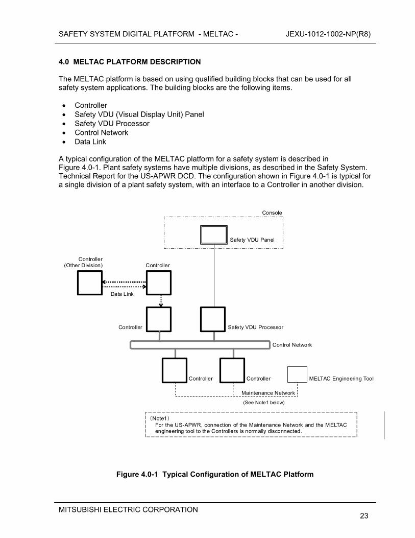
SAFETY SYSTEM DIGITAL PLATFORM - MELTAC - JEXU-1012-1002-NP(R8)
MITSUBISHI ELECTRIC CORPORATION
23
4.0 MELTAC PLATFORM DESCRIPTION The MELTAC platform is based on using qualified building blocks that can be used for all safety system applications. The building blocks are the following items. Controller Safety VDU (Visual Display Unit) Panel Safety VDU Processor Control Network Data Link
A typical configuration of the MELTAC platform for a safety system is described in Figure 4.0-1. Plant safety systems have multiple divisions, as described in the Safety System. Technical Report for the US-APWR DCD. The configuration shown in Figure 4.0-1 is typical for a single division of a plant safety system, with an interface to a Controller in another division.
ControllerController
Safety VDU Processor
Safety VDU Panel
Control Network
MELTAC Engineering Tool
Maintenance Network
Console
Controller (Other Division)
Data Link
Controller
Controller
(Note1) For the US-APWR, connection of the Maintenance Network and the MELTAC engineering tool to the Controllers is normally disconnected.
(See Note1 below)
Figure 4.0-1 Typical Configuration of MELTAC Platform
SAFETY SYSTEM DIGITAL PLATFORM - MELTAC - JEXU-1012-1002-NP(R8)
MITSUBISHI ELECTRIC CORPORATION
24
4.1 Controller 4.1.1 Hardware Configuration The Controller for the MELTAC platform consists of the following parts. a) One CPU Chassis including one or two Subsystems, one Switch Panel and one Fan Unit.
Each Subsystem consists of a Power Supply module, CPU Modules, Control Network I/F Module, System Management Module and two Bus Master Module. Each Subsystem communicates with the Control Network via its own Optical Switch.
b) Multiple Input/Output (I/O) Chassis, each with multiple I/O modules 4.1.1.1 Concept of Configuration The MELTAC platform is capable of taking three different kinds of configuration as shown below: a) Single Controller Configuration
The Controller includes one Subsystem. The Subsystem operates in Control Mode. (Control Mode means the Subsystem controls the outputs to plant components.)
b) Redundant Parallel Controller Configuration The Controller includes two Subsystems. Each Subsystem operates in Control Mode.
c) Redundant Standby Controller Configuration The Controller includes two Subsystems. One Subsystem operates in Control Mode while the other Subsystem operates in Standby Mode. Standby Mode means the Subsystem is closely monitoring the operation of the Subsystem in Control Mode, including memory states, so that if that Subsystem fails, the Subsystem operating in Standby Mode will automatically switch to Control Mode, with no bump in the control outputs.
The configuration to be applied is determined based on the application system requirements. Any of the three configurations may be applied to safety systems. For redundant configuration, the internally redundant Subsystems are only for reliability enhancement. This redundancy is not credited for single failure compliance. Single failure compliance is achieved through multiple controllers located in physically separate and independent safety divisions.
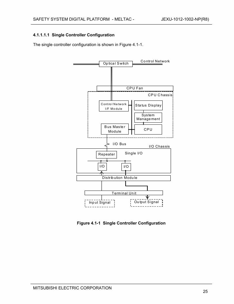
SAFETY SYSTEM DIGITAL PLATFORM - MELTAC - JEXU-1012-1002-NP(R8)
MITSUBISHI ELECTRIC CORPORATION
25
4.1.1.1.1 Single Controller Configuration The single controller configuration is shown in Figure 4.1-1.
Single I/O
I/O
Sys tem Manage ment
CP U B us Mas te r
Module
Repeater
I/O
CP U Fan
Inp ut Signal Ou tput S ignal
C ont ro l N e tw ork
I /F Mo dule S ta tus Display
Op tica l S witch
Dis tr ib ution Modu le
Term inal Un it
CP U C hass is
I/O BusI/O Chassis
Co ntrol Network
Figure 4.1-1 Single Controller Configuration
SAFETY SYSTEM DIGITAL PLATFORM - MELTAC - JEXU-1012-1002-NP(R8)
MITSUBISHI ELECTRIC CORPORATION
26
The Single Controller consists of the following: CPU Chassis The CPU Chassis includes one Subsystem, and a CPU Fan. A Subsystem consists of a CPU Module, System Management Module, Status Display Module, Control Network I/F Module and Bus Master Module. A Subsystem communicates with the Control Network via its own Optical Switch. The Subsystem is capable of taking a number of Control Network I/F Modules and Bus Master Modules depending on the scale of the application. Input/Output (I/O) Chassis The I/O Chassis includes only Single I/O. Single I/O consists of a Repeater Module and multiple I/O modules. Each I/O module communicates with the Bus Master Module in the Subsystem via the Repeater Module and the I/O Bus. The I/O modules receive signals from sensors and send control outputs to components via the Terminal Unit and Distribution Module. For Single I/O, the Distribution Module works as a surge absorber between the I/O modules and the Terminal Unit which connects external cables.
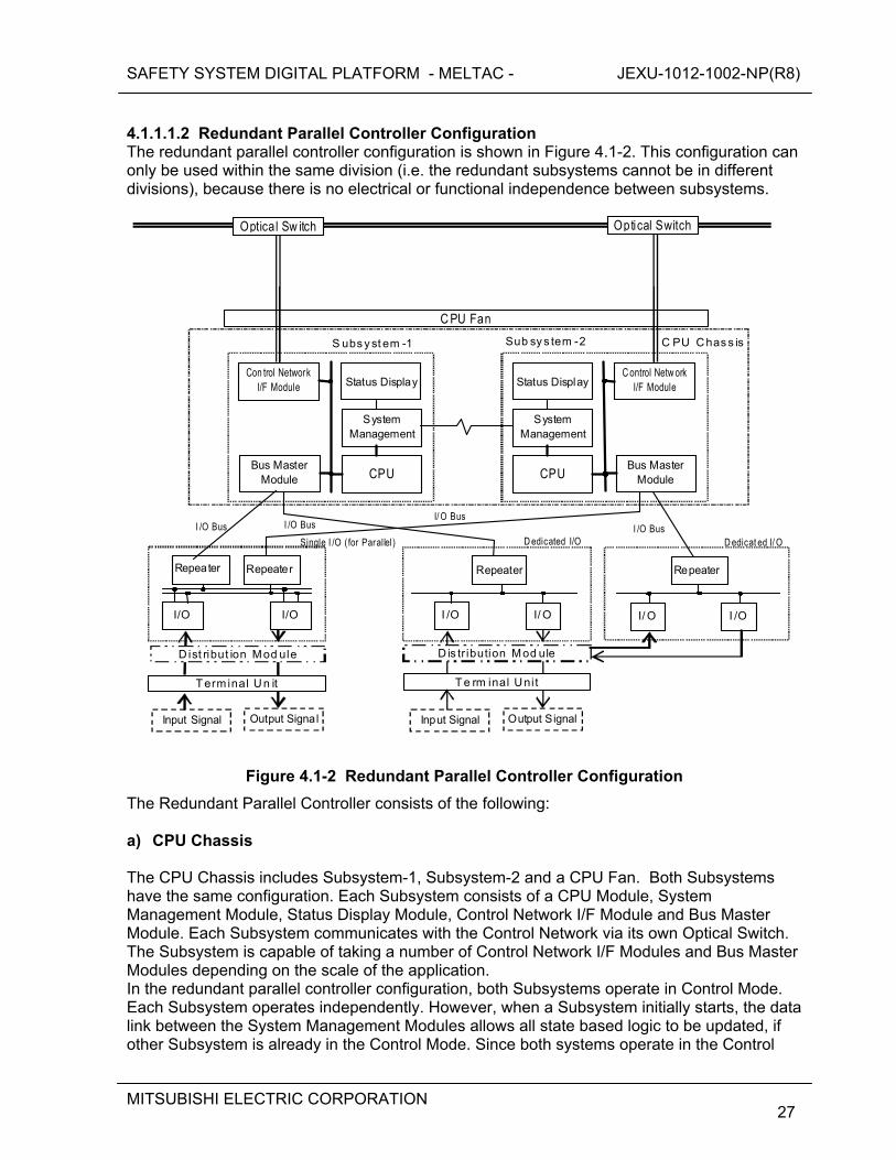
SAFETY SYSTEM DIGITAL PLATFORM - MELTAC - JEXU-1012-1002-NP(R8)
MITSUBISHI ELECTRIC CORPORATION
27
4.1.1.1.2 Redundant Parallel Controller Configuration The redundant parallel controller configuration is shown in Figure 4.1-2. This configuration can only be used within the same division (i.e. the redundant subsystems cannot be in different divisions), because there is no electrical or functional independence between subsystems.
C PU Chas s isSub sy s tem -2S ubs y st em -1
System Management
System Management
CPU CPU Bus Master
Module Bus Master
Module
I /OI/ O
C PU Fan
Con trol Network I/F Module
C ontrol Netw ork I/F Module
Optical Switch Optical Sw itch
Status Display Status Display
D edicat ed I/ O
I/O I/O
Repeater Repeater
Single I /O ( for Parallel)
Input Signal Output Signal
Repeater
I/ OI /O
Input Signal Output Signal
D is tr ibution Mod ule
T e rm inal Uni t
D edicated I/O
Repeater
T erm inal Un it
D ist ribut ion Mod ule
I /O Bus I /O Bus I/ O Bus
I /O Bus
Figure 4.1-2 Redundant Parallel Controller Configuration
The Redundant Parallel Controller consists of the following: a) CPU Chassis The CPU Chassis includes Subsystem-1, Subsystem-2 and a CPU Fan. Both Subsystems have the same configuration. Each Subsystem consists of a CPU Module, System Management Module, Status Display Module, Control Network I/F Module and Bus Master Module. Each Subsystem communicates with the Control Network via its own Optical Switch. The Subsystem is capable of taking a number of Control Network I/F Modules and Bus Master Modules depending on the scale of the application. In the redundant parallel controller configuration, both Subsystems operate in Control Mode. Each Subsystem operates independently. However, when a Subsystem initially starts, the data link between the System Management Modules allows all state based logic to be updated, if other Subsystem is already in the Control Mode. Since both systems operate in the Control
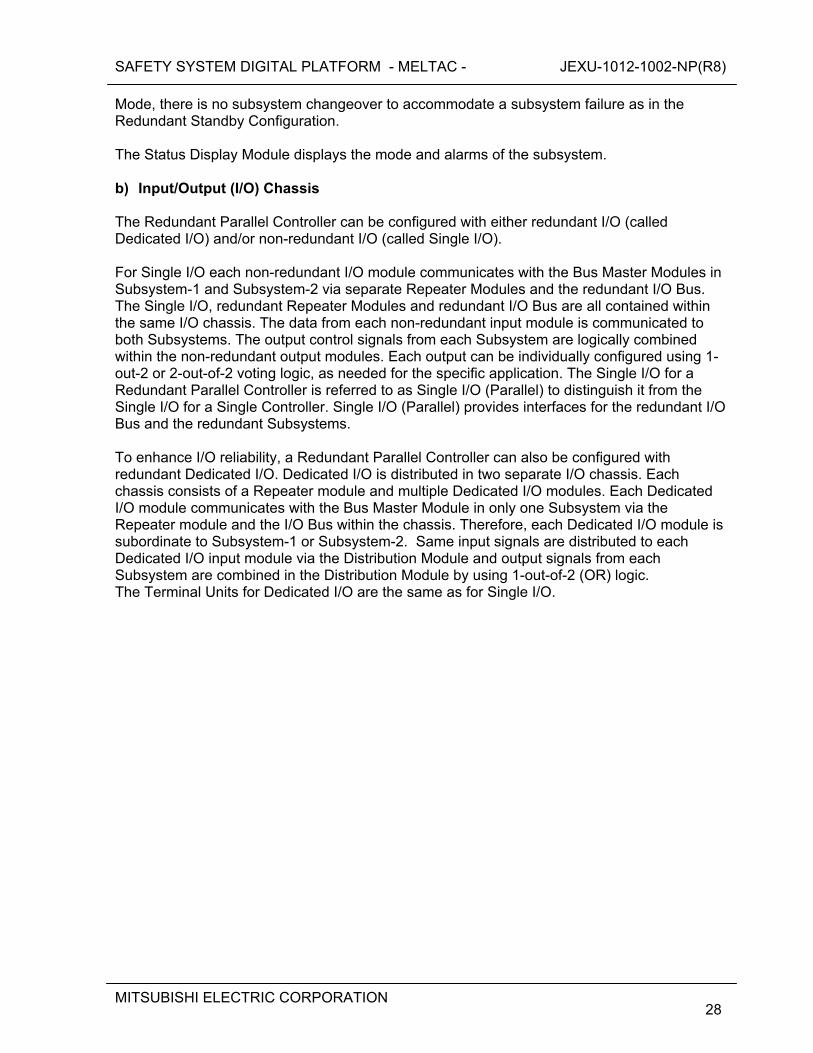
SAFETY SYSTEM DIGITAL PLATFORM - MELTAC - JEXU-1012-1002-NP(R8)
MITSUBISHI ELECTRIC CORPORATION
28
Mode, there is no subsystem changeover to accommodate a subsystem failure as in the Redundant Standby Configuration. The Status Display Module displays the mode and alarms of the subsystem. b) Input/Output (I/O) Chassis The Redundant Parallel Controller can be configured with either redundant I/O (called Dedicated I/O) and/or non-redundant I/O (called Single I/O). For Single I/O each non-redundant I/O module communicates with the Bus Master Modules in Subsystem-1 and Subsystem-2 via separate Repeater Modules and the redundant I/O Bus. The Single I/O, redundant Repeater Modules and redundant I/O Bus are all contained within the same I/O chassis. The data from each non-redundant input module is communicated to both Subsystems. The output control signals from each Subsystem are logically combined within the non-redundant output modules. Each output can be individually configured using 1-out-2 or 2-out-of-2 voting logic, as needed for the specific application. The Single I/O for a Redundant Parallel Controller is referred to as Single I/O (Parallel) to distinguish it from the Single I/O for a Single Controller. Single I/O (Parallel) provides interfaces for the redundant I/O Bus and the redundant Subsystems. To enhance I/O reliability, a Redundant Parallel Controller can also be configured with redundant Dedicated I/O. Dedicated I/O is distributed in two separate I/O chassis. Each chassis consists of a Repeater module and multiple Dedicated I/O modules. Each Dedicated I/O module communicates with the Bus Master Module in only one Subsystem via the Repeater module and the I/O Bus within the chassis. Therefore, each Dedicated I/O module is subordinate to Subsystem-1 or Subsystem-2. Same input signals are distributed to each Dedicated I/O input module via the Distribution Module and output signals from each Subsystem are combined in the Distribution Module by using 1-out-of-2 (OR) logic. The Terminal Units for Dedicated I/O are the same as for Single I/O.
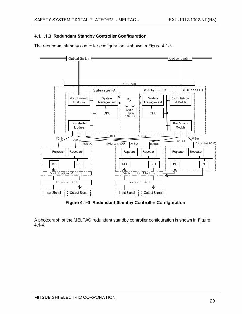
SAFETY SYSTEM DIGITAL PLATFORM - MELTAC - JEXU-1012-1002-NP(R8)
MITSUBISHI ELECTRIC CORPORATION
29
4.1.1.1.3 Redundant Standby Controller Configuration The redundant standby controller configuration is shown in Figure 4.1-3.
CP U c has s isS ub sy s tem -BS ubs y st em -A
I/ O
Repeater
System Management
System Management
Sta tus D isplay
& Sw itchCPU CPU
Repeater
I/O I/OI/O
RepeaterRepeater
I/OI /O
RepeaterRepeater
R edun dant I/O(S)
CPU Fan
Input Signal Output Signal
C ontrol Netw ork I/F Module
Optical Switch Optica l Sw itch
D is t r ib ut io n Mo dule
Term inal Un it
D is tr ibut ion Mo du le
Term in al Uni t
R edun dant I/O(P)Single I/ O
Input Signal Output Signal
Bus Master Module
Con trol Network I/F Module
Bus Master Module
I/O Bus I/O B us
I/O Bu sI/O Bu s
I/O BusI/O Bus
I/O Bus
I /O Bus
Figure 4.1-3 Redundant Standby Controller Configuration
A photograph of the MELTAC redundant standby controller configuration is shown in Figure 4.1-4.
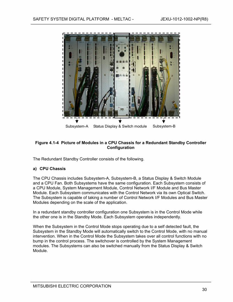
SAFETY SYSTEM DIGITAL PLATFORM - MELTAC - JEXU-1012-1002-NP(R8)
MITSUBISHI ELECTRIC CORPORATION
30
Subsystem-B Subsystem-A Status Display & Switch module
Figure 4.1-4 Picture of Modules in a CPU Chassis for a Redundant Standby Controller Configuration
The Redundant Standby Controller consists of the following. a) CPU Chassis The CPU Chassis includes Subsystem-A, Subsystem-B, a Status Display & Switch Module and a CPU Fan. Both Subsystems have the same configuration. Each Subsystem consists of a CPU Module, System Management Module, Control Network I/F Module and Bus Master Module. Each Subsystem communicates with the Control Network via its own Optical Switch. The Subsystem is capable of taking a number of Control Network I/F Modules and Bus Master Modules depending on the scale of the application. In a redundant standby controller configuration one Subsystem is in the Control Mode while the other one is in the Standby Mode. Each Subsystem operates independently. When the Subsystem in the Control Mode stops operating due to a self detected fault, the Subsystem in the Standby Mode will automatically switch to the Control Mode, with no manual intervention. When in the Control Mode the Subsystem takes over all control functions with no bump in the control process. The switchover is controlled by the System Management modules. The Subsystems can also be switched manually from the Status Display & Switch Module.
SAFETY SYSTEM DIGITAL PLATFORM - MELTAC - JEXU-1012-1002-NP(R8)
MITSUBISHI ELECTRIC CORPORATION
31
b) Input/Output (I/O) Chassis The Redundant Standby Controller includes either Redundant I/O and/or Single I/O. The Single I/O consists of two Repeater modules, a non-redundant I/O Bus and multiple I/O modules. Each I/O module communicates with the Bus Master Module for the Subsystem in the Control Mode. When the Subsystems switch modes, communication with the I/O modules also switches. Process input signals and output signals are connected to Single I/O via the Distribution Module and Terminal Unit. To enhance I/O reliability, a Redundant Standby Controller can also be configured with Redundant I/O. The Redundant I/O consists of Redundant I/O primary (P) and Redundant I/O secondary (S). Two I/O modules (primary and secondary) are utilized to interface with one field signal via the Distribution Module and Terminal Unit. However, like the Subsystems, one I/O module is in the Control Mode and the other is in the Standby Mode. Only the I/O module in the Control Mode generates output signals. The Subsystem in the Control Mode decides which I/O module is in the Control Mode based on communication self-diagnostics. Each I/O module communicates only with the Subsystem in the Control mode via the I/O Bus, Repeater Module and Bus Master Module.
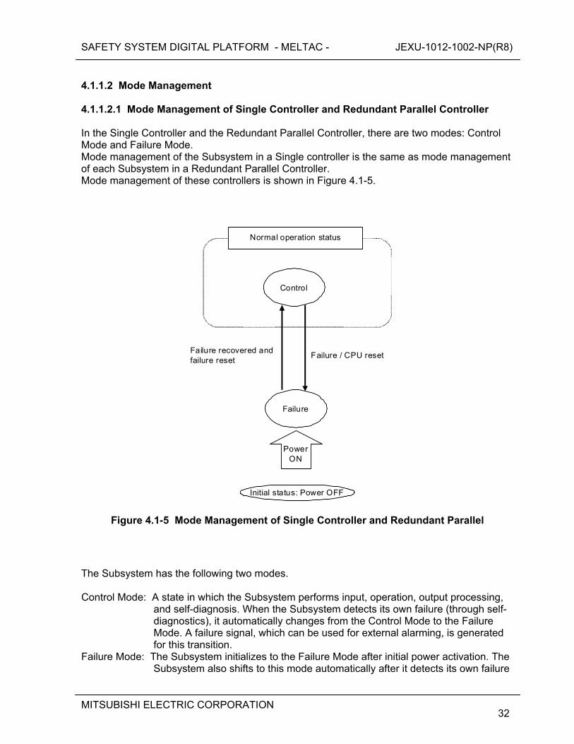
SAFETY SYSTEM DIGITAL PLATFORM - MELTAC - JEXU-1012-1002-NP(R8)
MITSUBISHI ELECTRIC CORPORATION
32
4.1.1.2 Mode Management 4.1.1.2.1 Mode Management of Single Controller and Redundant Parallel Controller In the Single Controller and the Redundant Parallel Controller, there are two modes: Control Mode and Failure Mode. Mode management of the Subsystem in a Single controller is the same as mode management of each Subsystem in a Redundant Parallel Controller. Mode management of these controllers is shown in Figure 4.1-5.
Normal operation status
Control
Power ON
Failure / CPU reset Failure recovered and failure reset
Initial status: Power OFF
Failure
Figure 4.1-5 Mode Management of Single Controller and Redundant Parallel
The Subsystem has the following two modes. Control Mode: A state in which the Subsystem performs input, operation, output processing,
and self-diagnosis. When the Subsystem detects its own failure (through self-diagnostics), it automatically changes from the Control Mode to the Failure Mode. A failure signal, which can be used for external alarming, is generated for this transition.
Failure Mode: The Subsystem initializes to the Failure Mode after initial power activation. The Subsystem also shifts to this mode automatically after it detects its own failure
SAFETY SYSTEM DIGITAL PLATFORM - MELTAC - JEXU-1012-1002-NP(R8)
MITSUBISHI ELECTRIC CORPORATION
33
or there is a loss of power greater than 20msec. A Subsystem shifts from the Failure Mode to the Control Mode only by pushing the reset button on the Status Display module.
In the Parallel Redundant Controller, Subsystem-A and Subsystem-B operate independently with the Mode Management described above, including failure detection, loss of power detection and manual reset. Analog and digital outputs can be held in their preset initial mode, after the Subsystem shifts to the Control Mode, until the Output Start button on the Status Display Module is pushed. After pushing the output start button, output updating by the controller is enabled. For the redundant parallel controller configuration there are separate Output Start buttons for each controller. Pushing either button will enable output updating for the respective controller. The output holding function can be disabled or enabled in the application program configuration. If this function is disabled, the outputs are enabled immediately after the Subsystem shifts to the Control Mode, without pushing the output start button. This function is enabled if it is required to confirm that the status of application software (POL) outputs matches the status of actual output devices before enabling output updating.
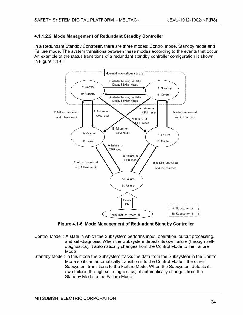
SAFETY SYSTEM DIGITAL PLATFORM - MELTAC - JEXU-1012-1002-NP(R8)
MITSUBISHI ELECTRIC CORPORATION
34
4.1.1.2.2 Mode Management of Redundant Standby Controller In a Redundant Standby Controller, there are three modes: Control mode, Standby mode and Failure mode. The system transitions between these modes according to the events that occur. An example of the status transitions of a redundant standby controller configuration is shown in Figure 4.1-6.
Normal operation status
A: Control
B: Standby
A: Standby
B: Control
A: Control
B: Failure
A: Failure
B: Control
A: Failure
B: Failure
Initial status: Power OFF
Power
ON
A failure or
CPU reset
A failure recovered
and failure reset
B selected by using the Status Display & Switch Module
A selected by using the Status Display & Switch Module
A failure recovered
and failure reset
B failure recovered
and failure reset
B failure recovered
and failure reset
A: Subsystem-A
B: Subsystem-B
A failure or
CPU reset
B failure or
CPU reset
B failure or
CPU reset
A failure or
CPU reset
B failure or
CPU reset
Figure 4.1-6 Mode Management of Redundant Standby Controller
Control Mode : A state in which the Subsystem performs input, operation, output processing,
and self-diagnosis. When the Subsystem detects its own failure (through self-diagnostics), it automatically changes from the Control Mode to the Failure Mode
Standby Mode : In this mode the Subsystem tracks the data from the Subsystem in the Control Mode so it can automatically transition into the Control Mode if the other Subsystem transitions to the Failure Mode. When the Subsystem detects its own failure (through self-diagnostics), it automatically changes from the Standby Mode to the Failure Mode.
SAFETY SYSTEM DIGITAL PLATFORM - MELTAC - JEXU-1012-1002-NP(R8)
MITSUBISHI ELECTRIC CORPORATION
35
Failure Mode : The Subsystem is initialized to the Failure Mode after initial power activation. The Subsystem also shifts to this mode automatically after it detects its own failure. A Subsystem shifts from the Failure Mode to the Control Mode or Standby Mode only by pushing the reset button on the Status Display & Switch Module. If there is no Subsystem in Control Mode, the Subsystem switches to the Control Mode when the reset button is pushed. If a Subsystem is already in the Control Mode, the Subsystem switches to the Standby Mode when the reset button is pushed.
Analog and digital outputs can be held in their preset initial mode, after the Subsystem shifts to the Control Mode, until the Output Start button on the Status Display & Switch Module is pushed. After pushing the Output Start button, output updating by the controller is enabled. For the redundant standby controller configuration there is one common Output Start button. Pushing the button will enable output updating for the Redundant Standby Controller. The output holding function can be disabled or enabled in the application program configuration same as Mode Management of Single Controller and Redundant Parallel Controller described in 4.1.1.2.1.
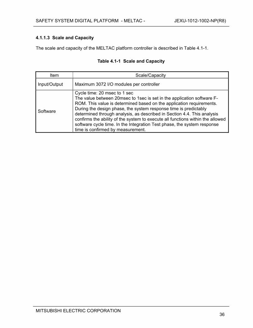
SAFETY SYSTEM DIGITAL PLATFORM - MELTAC - JEXU-1012-1002-NP(R8)
MITSUBISHI ELECTRIC CORPORATION
36
4.1.1.3 Scale and Capacity The scale and capacity of the MELTAC platform controller is described in Table 4.1-1.
Table 4.1-1 Scale and Capacity
Item Scale/Capacity
Input/Output Maximum 3072 I/O modules per controller
Software
Cycle time: 20 msec to 1 sec The value between 20msec to 1sec is set in the application software F-ROM. This value is determined based on the application requirements. During the design phase, the system response time is predictably determined through analysis, as described in Section 4.4. This analysis confirms the ability of the system to execute all functions within the allowed software cycle time. In the Integration Test phase, the system response time is confirmed by measurement.
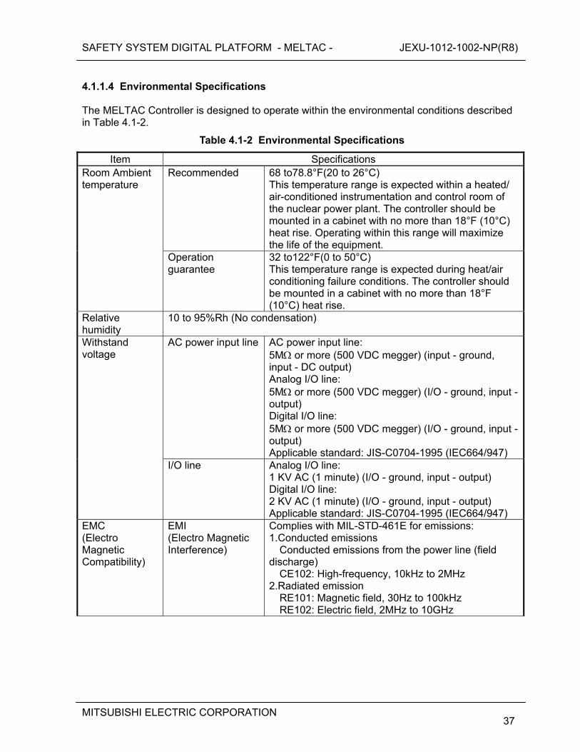
SAFETY SYSTEM DIGITAL PLATFORM - MELTAC - JEXU-1012-1002-NP(R8)
MITSUBISHI ELECTRIC CORPORATION
37
4.1.1.4 Environmental Specifications The MELTAC Controller is designed to operate within the environmental conditions described in Table 4.1-2.
Table 4.1-2 Environmental Specifications
Item Specifications Recommended 68 to78.8°F(20 to 26°C)
This temperature range is expected within a heated/ air-conditioned instrumentation and control room of the nuclear power plant. The controller should be mounted in a cabinet with no more than 18°F (10°C) heat rise. Operating within this range will maximize the life of the equipment.
Room Ambient temperature
Operation guarantee
32 to122°F(0 to 50°C) This temperature range is expected during heat/air conditioning failure conditions. The controller should be mounted in a cabinet with no more than 18°F (10°C) heat rise.
Relative humidity
10 to 95%Rh (No condensation)
AC power input line AC power input line: 5M or more (500 VDC megger) (input - ground, input - DC output) Analog I/O line: 5M or more (500 VDC megger) (I/O - ground, input - output) Digital I/O line: 5M or more (500 VDC megger) (I/O - ground, input - output) Applicable standard: JIS-C0704-1995 (IEC664/947)
Withstand voltage
I/O line Analog I/O line: 1 KV AC (1 minute) (I/O - ground, input - output) Digital I/O line: 2 KV AC (1 minute) (I/O - ground, input - output) Applicable standard: JIS-C0704-1995 (IEC664/947)
EMC (Electro Magnetic Compatibility)
EMI (Electro Magnetic Interference)
Complies with MIL-STD-461E for emissions: 1.Conducted emissions
Conducted emissions from the power line (field discharge)
CE102: High-frequency, 10kHz to 2MHz 2.Radiated emission
RE101: Magnetic field, 30Hz to 100kHz RE102: Electric field, 2MHz to 10GHz
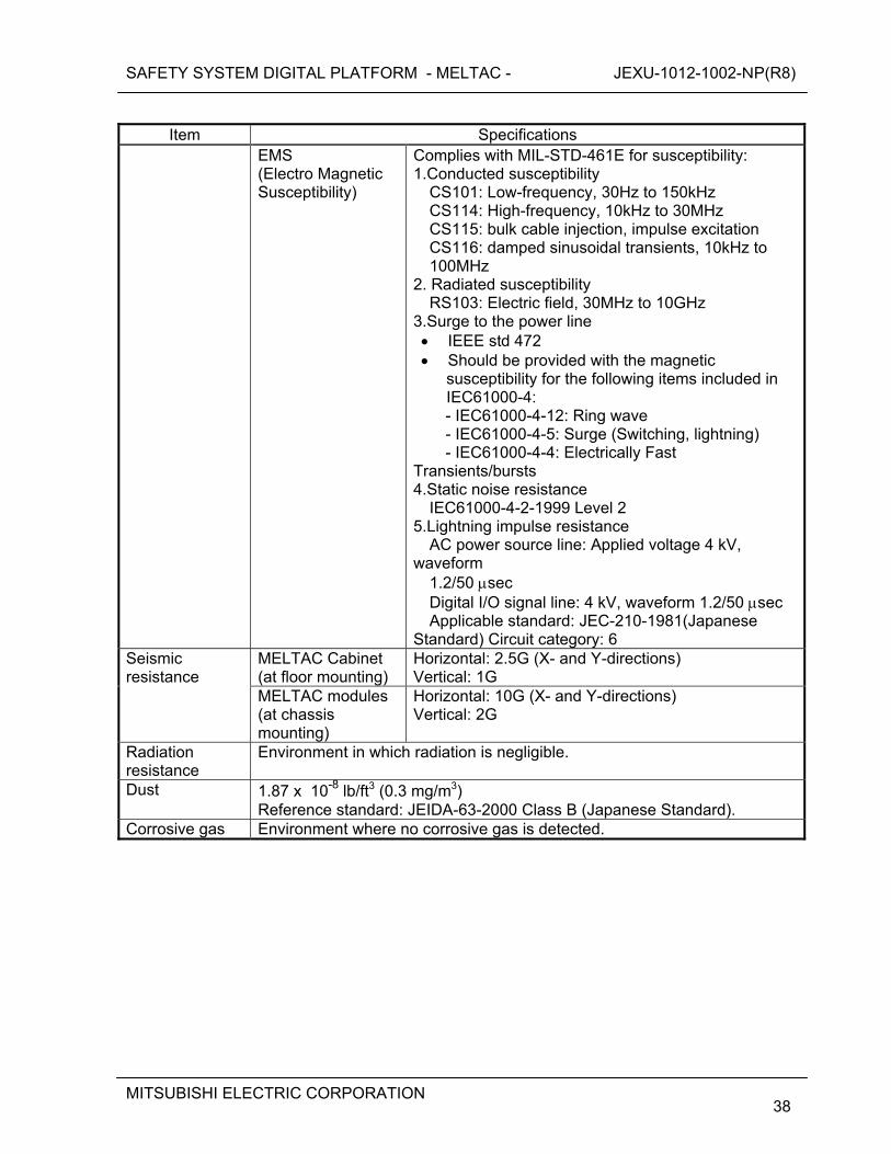
SAFETY SYSTEM DIGITAL PLATFORM - MELTAC - JEXU-1012-1002-NP(R8)
MITSUBISHI ELECTRIC CORPORATION
38
Item Specifications
EMS (Electro Magnetic Susceptibility)
Complies with MIL-STD-461E for susceptibility: 1.Conducted susceptibility
CS101: Low-frequency, 30Hz to 150kHz CS114: High-frequency, 10kHz to 30MHz CS115: bulk cable injection, impulse excitation CS116: damped sinusoidal transients, 10kHz to 100MHz
2. Radiated susceptibility RS103: Electric field, 30MHz to 10GHz
3.Surge to the power line IEEE std 472 Should be provided with the magnetic
susceptibility for the following items included in IEC61000-4: - IEC61000-4-12: Ring wave - IEC61000-4-5: Surge (Switching, lightning) - IEC61000-4-4: Electrically Fast
Transients/bursts 4.Static noise resistance
IEC61000-4-2-1999 Level 2 5.Lightning impulse resistance
AC power source line: Applied voltage 4 kV, waveform
1.2/50 sec Digital I/O signal line: 4 kV, waveform 1.2/50 sec Applicable standard: JEC-210-1981(Japanese
Standard) Circuit category: 6 MELTAC Cabinet (at floor mounting)
Horizontal: 2.5G (X- and Y-directions) Vertical: 1G
Seismic resistance
MELTAC modules (at chassis mounting)
Horizontal: 10G (X- and Y-directions) Vertical: 2G
Radiation resistance
Environment in which radiation is negligible.
Dust 1.87 x 10⁻⁸ lb/ft3 (0.3 mg/m3) Reference standard: JEIDA-63-2000 Class B (Japanese Standard).
Corrosive gas Environment where no corrosive gas is detected.
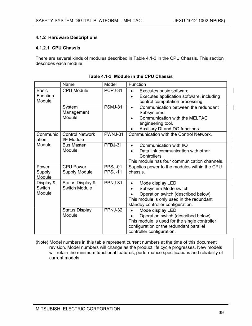
SAFETY SYSTEM DIGITAL PLATFORM - MELTAC - JEXU-1012-1002-NP(R8)
MITSUBISHI ELECTRIC CORPORATION
39
4.1.2 Hardware Descriptions 4.1.2.1 CPU Chassis There are several kinds of modules described in Table 4.1-3 in the CPU Chassis. This section describes each module.
Table 4.1-3 Module in the CPU Chassis
Name Model Function CPU Module PCPJ-31 Executes basic software
Executes application software, including control computation processing
Basic Function Module
System Management Module
PSMJ-31 Communication between the redundant Subsystems
Communication with the MELTAC engineering tool.
Auxiliary DI and DO functions Control Network I/F Module
PWNJ-31 Communication with the Control Network. Communication Module Bus Master
Module PFBJ-31 Communication with I/O
Data link communication with other Controllers
This module has four communication channels.Power Supply Module
CPU Power Supply Module
PPSJ-01 PPSJ-11
Supplies power to the modules within the CPU chassis.
Status Display & Switch Module
PPNJ-31 Mode display LED Subsystem Mode switch Operation switch (described below)
This module is only used in the redundant standby controller configuration.
Display & Switch Module
Status Display Module
PPNJ-32 Mode display LED Operation switch (described below)
This module is used for the single controller configuration or the redundant parallel controller configuration.
(Note) Model numbers in this table represent current numbers at the time of this document
revision. Model numbers will change as the product life cycle progresses. New models will retain the minimum functional features, performance specifications and reliability of current models.
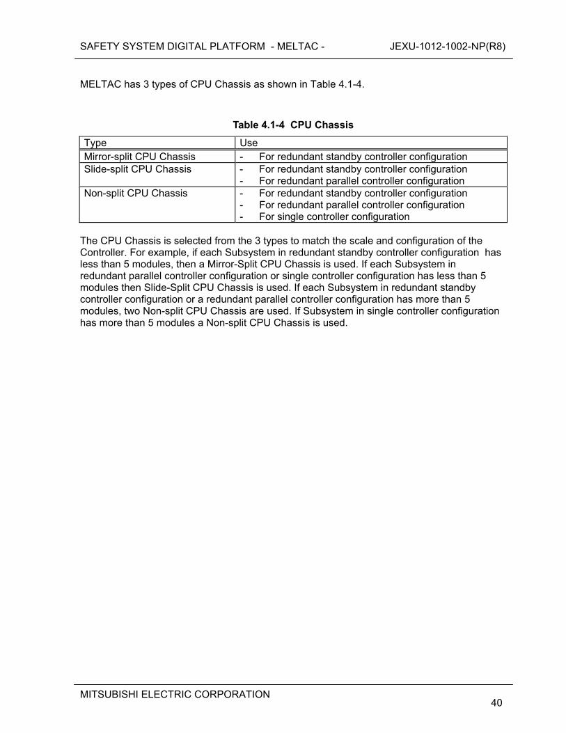
SAFETY SYSTEM DIGITAL PLATFORM - MELTAC - JEXU-1012-1002-NP(R8)
MITSUBISHI ELECTRIC CORPORATION
40
MELTAC has 3 types of CPU Chassis as shown in Table 4.1-4.
Table 4.1-4 CPU Chassis
Type Use Mirror-split CPU Chassis - For redundant standby controller configuration Slide-split CPU Chassis - For redundant standby controller configuration
- For redundant parallel controller configuration Non-split CPU Chassis - For redundant standby controller configuration
- For redundant parallel controller configuration - For single controller configuration
The CPU Chassis is selected from the 3 types to match the scale and configuration of the Controller. For example, if each Subsystem in redundant standby controller configuration has less than 5 modules, then a Mirror-Split CPU Chassis is used. If each Subsystem in redundant parallel controller configuration or single controller configuration has less than 5 modules then Slide-Split CPU Chassis is used. If each Subsystem in redundant standby controller configuration or a redundant parallel controller configuration has more than 5 modules, two Non-split CPU Chassis are used. If Subsystem in single controller configuration has more than 5 modules a Non-split CPU Chassis is used.
SAFETY SYSTEM DIGITAL PLATFORM - MELTAC - JEXU-1012-1002-NP(R8)
MITSUBISHI ELECTRIC CORPORATION
41
4.1.2.1.1 CPU Module (PCPJ-31) The CPU Module utilizes a 32-bit microprocessor, with enhanced speed due to the cache. This processor module is IEEE standard Futurebus+ compliant, and performs internal operations and data transmission with other modules (i.e. Bus Master Module, Control Network I/F Module and System Management Module) via Futurebus+. The data transfer between the CPU Module and other modules is asynchronous. All modules have separate clocks. This module utilizes F-ROM (Flash Electrically Erasable Programmable Read Only Memory) for storing the basic software and F-ROM for storing the application software, such as logic symbol interconnections, setpoints and constants. Specifications of the CPU Module are in Appendix A.1. 4.1.2.1.2 System Management Module (PSMJ-31) The System Management Module monitors the status of the CPU Module and executes auxiliary controller functions that are not directly related to the CPU Module. This module has the following functions:
Auxiliary DI/DO for generating alarms such as fan failure. Ethernet interface for communicating with the MELTAC engineering tool. Transmits and receives the changeover signal for Redundant Subsystem
configurations via a dedicated backplane bus, as shown in Figure 4.1-3. In addition, this module is provided with a 2-port memory data link used for that the Standby Mode Subsystem receives operation data from the Control Mode Subsystem.
Specifications of System Management Module are in Appendix A.2. 4.1.2.1.3 Bus Master Module (PFBJ-31) The Bus Master Module has a 4 communication interface channels. Either of the following two functions can be defined for each channel.
Communication with I/O modules This module is IEEE standard Futurebus+ compliant. It has 2-port memory, allowing the CPU Module to deliver process I/O data via Futurebus+. Each communication channel is capable of controlling 96 I/O modules, enabling control of a maximum of 384 I/O modules per Bus Master Module.
Data Link communication The Bus Master Module implements serial data link communication between controllers in separate safety divisions. The Bus Master Module employs 2-port memory to ensure communication functions do not disrupt deterministic CPU operation. Description of the Data Link is shown in Section 4.3.3.
Specifications of the Bus Master Module are in Appendix A.3.
SAFETY SYSTEM DIGITAL PLATFORM - MELTAC - JEXU-1012-1002-NP(R8)
MITSUBISHI ELECTRIC CORPORATION
42
4.1.2.1.4 Control Network I/F Module (PWNJ-31) The Control Network I/F Module connects the Controller to the Control Network. This interface employs a Resilient Packet Ring (RPR) based on IEEE standard 802.17. The Control Network is redundant using optical fiber as the communication medium. An optical switch unit enables optical bypass for system maintenance. The Control Network I/F Module employs 2-port memory to ensure communication functions do not disrupt deterministic CPU operation. The description of the Control Network, including the Control Network I/F Module is shown in Section 4.3.2. 4.1.2.1.5 Status Display & Switch Module (PPNJ-31) The Status Display & Switch Module is used in a CPU Chassis configured for a Redundant Standby Controller. This module displays the mode and alarms of the Subsystems and provides the manual mode change over switch. 4.1.2.1.6 Status Display Module (PPNJ-32) The Status Display Module is used in a CPU Chassis configured for a Redundant Parallel Controller or Single Controller. It is connected with the CPU Module by wiring on the back plane. This module displays the mode and alarms of the single Subsystems to which it is directly connected there is no connection with the other subsystems.
SAFETY SYSTEM DIGITAL PLATFORM - MELTAC - JEXU-1012-1002-NP(R8)
MITSUBISHI ELECTRIC CORPORATION
43
4.1.2.2 Input/Output (I/O) Modules The I/O modules in the MELTAC platform include the process input/output function and the signal conditioner function, including signal conversion and noise reduction. The MELTAC platform includes several types of analog and digital modules to accommodate various input/output signal interfaces. The I/O modules are mounted in Dedicated I/O Chassis. One I/O Chassis can accommodate 16 modules. The modules mounted in the Chassis are connected to the Bus Master Modules in the CPU Chassis via Repeater Modules that can shape and amplify data communication signals. Data transfer is achieved via the I/O Bus. There are one analog input or output per analog I/O module and four digital inputs or outputs per digital I/O module. Dedicated I/O modules are applied for NIS and RMS. These modules provide unique signal processing for neutron monitoring and radiation monitoring detectors. These I/O modules are mounted in the dedicated chassis installed in the dedicated cabinets for NIS and RMS, respectively. NIS and RMS I/O modules are connected to MELTAC Bus Master Modules in the CPU chassis, the same as described above. Specifications of I/O modules are in Appendix A5.
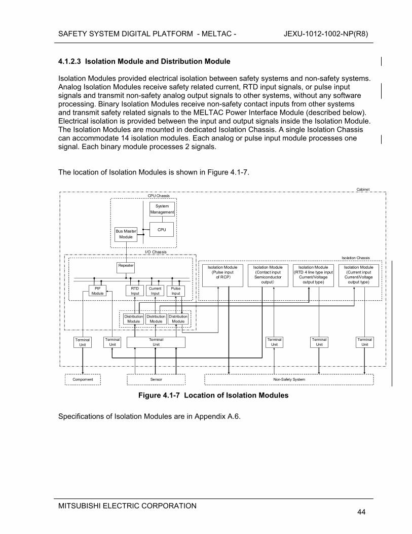
SAFETY SYSTEM DIGITAL PLATFORM - MELTAC - JEXU-1012-1002-NP(R8)
MITSUBISHI ELECTRIC CORPORATION
44
4.1.2.3 Isolation Module and Distribution Module Isolation Modules provided electrical isolation between safety systems and non-safety systems. Analog Isolation Modules receive safety related current, RTD input signals, or pulse input signals and transmit non-safety analog output signals to other systems, without any software processing. Binary Isolation Modules receive non-safety contact inputs from other systems and transmit safety related signals to the MELTAC Power Interface Module (described below). Electrical isolation is provided between the input and output signals inside the Isolation Module. The Isolation Modules are mounted in dedicated Isolation Chassis. A single Isolation Chassis can accommodate 14 isolation modules. Each analog or pulse input module processes one signal. Each binary module processes 2 signals. The location of Isolation Modules is shown in Figure 4.1-7.
Cabinet
Current Input
RTD Input
PIF Module
CPU Chassis
Repeater
I/O Chassis
Terminal Unit
Terminal Unit
Distribution Module
Distribution Module
Bus Master
Module
System
Management
CPU
Terminal Unit
Compornent Sensor
Isolation Module (RTD 4 line type input
Current/Voltage output type)
Isolation Chassis
Isolation Module (Current input
Current/Voltage output type)
Isolation Module (Contact input Semiconductor
output)
TerminalUnit
Terminal Unit
TerminalUnit
Non-Safety System
Isolation Module (Pulse input
of RCP)
Pulse Input
DistributionModule
Figure 4.1-7 Location of Isolation Modules
Specifications of Isolation Modules are in Appendix A.6.
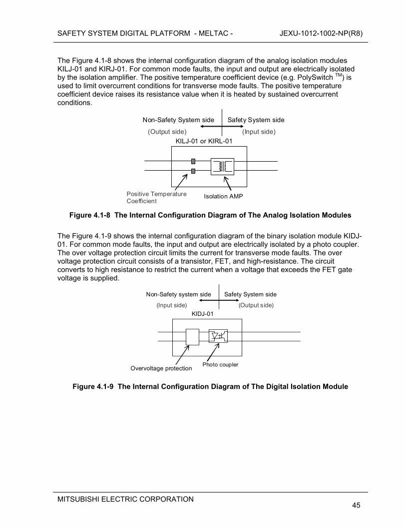
SAFETY SYSTEM DIGITAL PLATFORM - MELTAC - JEXU-1012-1002-NP(R8)
MITSUBISHI ELECTRIC CORPORATION
45
The Figure 4.1-8 shows the internal configuration diagram of the analog isolation modules KILJ-01 and KIRJ-01. For common mode faults, the input and output are electrically isolated by the isolation amplifier. The positive temperature coefficient device (e.g. PolySwitch TM) is used to limit overcurrent conditions for transverse mode faults. The positive temperature coefficient device raises its resistance value when it is heated by sustained overcurrent conditions.
KILJ-01 or KIRL-01
Safety System side Non-Safety System side
Positive Temperature Coefficient
Isolation AMP
(Output side) (Input side)
Figure 4.1-8 The Internal Configuration Diagram of The Analog Isolation Modules
The Figure 4.1-9 shows the internal configuration diagram of the binary isolation module KIDJ-01. For common mode faults, the input and output are electrically isolated by a photo coupler. The over voltage protection circuit limits the current for transverse mode faults. The over voltage protection circuit consists of a transistor, FET, and high-resistance. The circuit converts to high resistance to restrict the current when a voltage that exceeds the FET gate voltage is supplied.
KIDJ-01
Safety System side Non-Safety system side
Photo coupler Overvoltage protection
(Input side) (Output side)
Figure 4.1-9 The Internal Configuration Diagram of The Digital Isolation Module
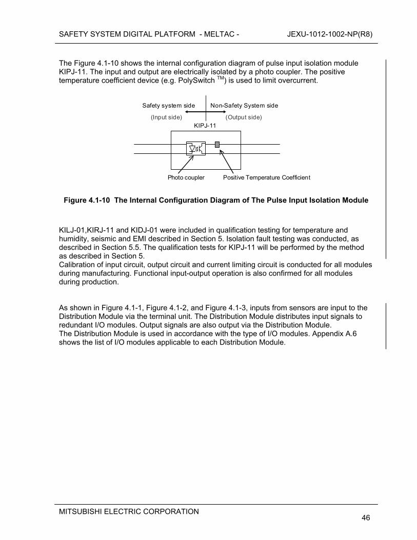
SAFETY SYSTEM DIGITAL PLATFORM - MELTAC - JEXU-1012-1002-NP(R8)
MITSUBISHI ELECTRIC CORPORATION
46
The Figure 4.1-10 shows the internal configuration diagram of pulse input isolation module KIPJ-11. The input and output are electrically isolated by a photo coupler. The positive temperature coefficient device (e.g. PolySwitch TM) is used to limit overcurrent.
KIPJ-11
Non-Safety System side Safety system side
Photo coupler
(Input side) (Output side)
Positive Temperature Coefficient
Figure 4.1-10 The Internal Configuration Diagram of The Pulse Input Isolation Module
KILJ-01,KIRJ-11 and KIDJ-01 were included in qualification testing for temperature and humidity, seismic and EMI described in Section 5. Isolation fault testing was conducted, as described in Section 5.5. The qualification tests for KIPJ-11 will be performed by the method as described in Section 5. Calibration of input circuit, output circuit and current limiting circuit is conducted for all modules during manufacturing. Functional input-output operation is also confirmed for all modules during production. As shown in Figure 4.1-1, Figure 4.1-2, and Figure 4.1-3, inputs from sensors are input to the Distribution Module via the terminal unit. The Distribution Module distributes input signals to redundant I/O modules. Output signals are also output via the Distribution Module. The Distribution Module is used in accordance with the type of I/O modules. Appendix A.6 shows the list of I/O modules applicable to each Distribution Module.
SAFETY SYSTEM DIGITAL PLATFORM - MELTAC - JEXU-1012-1002-NP(R8)
MITSUBISHI ELECTRIC CORPORATION
47
4.1.2.4 Power Interface Module The Power Interface (PIF) Modules have the same I/O Bus interfaces as in the I/O modules. These modules receive output commands as the result of Subsystem operation, and control the power that drives the switchgears, solenoid valves, etc. for plant components. This module utilizes power semiconductor devices for controlling power. Therefore, periodic replacement is unnecessary in contrast to electro-mechanical relays. The PIF Modules also receive inputs from external contacts (the status contacts of the components) and transmit component status signals to the Subsystem. The Power Interface Modules include Interposing Logic (IPL) sub-boards that control the components in direct response to external contact inputs, independent of the Subsystem output commands. There are several types of IPL sub-boards, for different types of plant components (eg. switchgears, solenoid valves, etc.). Each PIF is configured with the appropriate IPL sub-board for the component being controlled. The IPL is realized by discrete logic Integrated Circuits. [
]
All currently available IPL sub-boards have been qualified, as described in Section 5. However, it is anticipated that new IPL sub-boards may be required for US applications, due to changes in plant process components, changes in DAS interfaces and changes in priority logic, compared to applications in Japan. New IPL sub-boards will maintain the same design process, qualification process, hardware technology and quality program as current IPL sub-boards. The entire PIF module, including the Communications Interface part is considered Class 1E. Therefore, the life cycle process for the development and maintenance of the firmware within the Communications Interface part is the same as the firmware for all other MELTAC modules. During manufacturing and production, the PIF modules are all tested to confirm the soundness of communication operation, IPL logic operation, and output operation. Unlike electro-mechanical relays, the power semiconductor output of the PIF module does not degrade mechanically nor electrically and can be treated the same as any other general semiconductor device. Thus, the PIF modules are not considered to have any limitations in their expected service life. The components of the MELTAC platform that have a limited service life are identified in Section 7.5 Periodic Replacement Equipment (Parts) to Keep Reliability. The PIF is not included in this list.
SAFETY SYSTEM DIGITAL PLATFORM - MELTAC - JEXU-1012-1002-NP(R8)
MITSUBISHI ELECTRIC CORPORATION
48
Figure 4.1-11 The Internal Configuration Diagram of The PIF Module
Specifications of the Power Interface Module are in Appendix A.8. 4.1.2.5 Electrical/Optical Converter Module Electrical/Optical (E/O) Converter Modules for Data Link communication convert electrical signals to optical signals or optical signals to electrical signals. They are mounted in dedicated E/O Chassis. Up to 14 modules can be installed per Chassis, with one communication link per module. There is also an Ethernet Optical Isolation Module for the interface of the Maintenance Network to the System Management module. Specifications of the E/O Converter Module and Ethernet Optical Isolation Module are in Appendix A.7.
SAFETY SYSTEM DIGITAL PLATFORM - MELTAC - JEXU-1012-1002-NP(R8)
MITSUBISHI ELECTRIC CORPORATION
49
4.1.2.6 Optical Switch The Optical Switch is installed outside the CPU Chassis. It optically bypasses the Control Network communication line in the Control Network I/F Module during controller maintenance.
4.1.2.7 Fan Units 4.1.2.7.1 CPU Fan The CPU Fan is installed on the top of the CPU Chassis to cool the modules within the CPU Chassis. It is equipped with a fan stop detection circuit which provides a contact signal to the System Management Module. 4.1.2.7.2 Door Fan Unit The Door Fan Unit is installed at the top rear of the cabinet to cool internal cabinet components. It is equipped with a fan stop detection circuit which provides a contact signal to the System Management Module. 4.1.2.7.3 Power Supply Fan Units The Power Supply Fan Units are installed at the bottom and the midsection on both the left- and right-hand sides of the cabinet to cool the power supplies, PS-1 and PS-2. It is equipped with a fan stop detection circuit which provides a contact signal to the System Management Module. The fan stop detection circuit detects the decrease of fan rotation frequency by converting fan rotation frequency into a voltage pulse and monitoring the pulse length. If the pulse length reaches the length equivalent to the detected rotation frequency limit, the fan stop detection circuit de-energizes a relay, which generates a contact closing signal. Also, the same relay is deenergized if there is a power loss to the fan. Therefore, fan failure can be detected. 4.1.2.8 Power Supply Module The Power Supply Modules convert the AC power supplied to the Chassis from two independent sources to DC power voltages suitable for the individual modules and units. Redundant Power Supply Modules are provided for CPU Chassis, I/O modules, Isolation Modules, Power Interface Modules, E/O Converter Modules and fan units. There are two types of Power Supply Modules. The CPU Power Supply (PS-1, PPSJ-01 and PPSJ-11) provides multiple outputs of +2.1VDC and +5VDC for the CPU Chassis. The I/O Power Supply (PS-2) provides +24VDC for I/O modules, Isolation Modules, Power Interface Modules, E/O Converter Modules and fan units. PPSJ-01 and PPSJ-11 are mounted in the CPU Chassis. These Power Supplies apply to the redundant parallel controller configuration.
SAFETY SYSTEM DIGITAL PLATFORM - MELTAC - JEXU-1012-1002-NP(R8)
MITSUBISHI ELECTRIC CORPORATION
50
PS-1 and PS-2 are mounted outside of the chassis. These Power Supplies apply to the single controller configuration where the power supply is redundant for the CPU Chassis. PS-1 and PS-2 are mounted on the panel cut parts that are set right and left of the cabinet chassis as shown in the Figure 4.1-11, Figure 4.1-12 and Figure 4.1-13. This mounting location was selected, rather than mounting them within the chassis for three reasons (1) this leaves space in the chassis for additional modules, (2) external mounting allows DC power to be supplied to the chassis from two redundant Power Supply Modules, (3) this location keeps the heat from the power supplies away from the modules, thereby improving module reliability. Both types of Power Supply Modules are equipped with overvoltage protection that deenergizes the output when the output voltage exceeds a setting, and overcurrent protection that lowers the output voltage level when an overload or output short-circuit occurs. Both types of Power Supply Modules also provide a contact output alarm signal when an output shut-down occurs. For a redundant standby controller configuration and a redundant parallel controller configuration, each Subsystem monitors the output condition of the other Subsystem’s Power Supply Module. For a redundant standby controller configuration, when there is a shutdown of the power supply module of the Subsystem in the Control Mode, the Subsystem in the Standby Mode shifts to the Control Mode. When there is a shutdown of the power supply module of the Subsystem in the Standby Mode, the Subsystem in the Control Mode generates an “Alarm”. For a redundant parallel controller configuration, each Subsystem warns “Alarm" if there is a shutdown of the power supply module of the other Subsystem. The CPU Power Supply Module is also equipped with AC power input monitoring. When the AC power input is lost, it is detected by the AC power reduction detection circuit within the power supply, and an alarm signal is output to the CPU Module. When the CPU Module receives an alarm signal for loss of AC power from its own Subsystem’s Power Supply Module, the CPU Module shifts to the “Failure" Mode before the Power Supply Module output voltage level becomes lower than the operable voltage of the CPU Module. For a redundant standby controller configuration, if the AC power input for the Subsystem in the Control Mode is lost, the Subsystem shifts to the “Failure” Mode, then the Power Supply Module outputs shuts down. The Subsystem in the Standby Mode shifts to the Control Mode by detecting a failure or a shutdown of the power supply module of the other Subsystem. Specifications of the Power Supply Modules are in Appendix A.9.
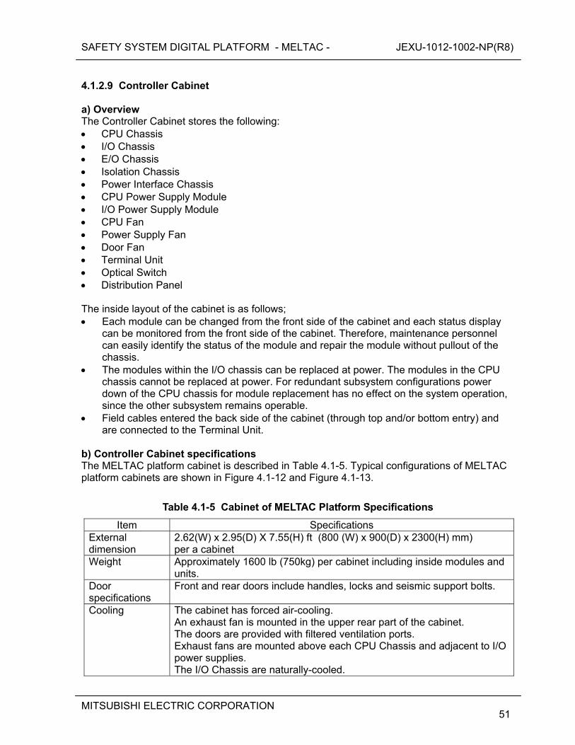
SAFETY SYSTEM DIGITAL PLATFORM - MELTAC - JEXU-1012-1002-NP(R8)
MITSUBISHI ELECTRIC CORPORATION
51
4.1.2.9 Controller Cabinet a) Overview The Controller Cabinet stores the following: CPU Chassis I/O Chassis E/O Chassis Isolation Chassis Power Interface Chassis CPU Power Supply Module I/O Power Supply Module CPU Fan Power Supply Fan Door Fan Terminal Unit Optical Switch Distribution Panel The inside layout of the cabinet is as follows; Each module can be changed from the front side of the cabinet and each status display
can be monitored from the front side of the cabinet. Therefore, maintenance personnel can easily identify the status of the module and repair the module without pullout of the chassis.
The modules within the I/O chassis can be replaced at power. The modules in the CPU chassis cannot be replaced at power. For redundant subsystem configurations power down of the CPU chassis for module replacement has no effect on the system operation, since the other subsystem remains operable.
Field cables entered the back side of the cabinet (through top and/or bottom entry) and are connected to the Terminal Unit.
b) Controller Cabinet specifications The MELTAC platform cabinet is described in Table 4.1-5. Typical configurations of MELTAC platform cabinets are shown in Figure 4.1-12 and Figure 4.1-13.
Table 4.1-5 Cabinet of MELTAC Platform Specifications
Item Specifications External dimension
2.62(W) x 2.95(D) X 7.55(H) ft (800 (W) x 900(D) x 2300(H) mm) per a cabinet
Weight Approximately 1600 lb (750kg) per cabinet including inside modules and units.
Door specifications
Front and rear doors include handles, locks and seismic support bolts.
Cooling The cabinet has forced air-cooling. An exhaust fan is mounted in the upper rear part of the cabinet. The doors are provided with filtered ventilation ports. Exhaust fans are mounted above each CPU Chassis and adjacent to I/O power supplies. The I/O Chassis are naturally-cooled.

SAFETY SYSTEM DIGITAL PLATFORM - MELTAC - JEXU-1012-1002-NP(R8)
MITSUBISHI ELECTRIC CORPORATION
52
Figure 4.1-12 Cabinet External Dimensions and Rack Up, Typical Sample A
SAFETY SYSTEM DIGITAL PLATFORM - MELTAC - JEXU-1012-1002-NP(R8)
MITSUBISHI ELECTRIC CORPORATION
53
Figure 4.1-13 Cabinet External Dimensions and Rack Up, Typical Sample B
SAFETY SYSTEM DIGITAL PLATFORM - MELTAC - JEXU-1012-1002-NP(R8)
MITSUBISHI ELECTRIC CORPORATION
54
4.1.2.10 Power Supply Configuration Redundant AC power from two separate sources is supplied to the MELTAC Cabinet to avoid loss of function due to a single failure in the power supply or power source, as shown in Figure 4.1-14. The two AC power sources are from within the same safety division, but should not have a realistic single malfunction point that would result in simultaneously failure. It is important to note that power redundancy is only for system available. There is no credit for this power redundancy in complying with the Single Failure Criteria of IEEE 379, since compliance to IEEE 379 is achieved by having separate trains. The source of AC power is described in system application documentation. The AC power is filtered and converted to DC voltage by the Power Supply modules. DC power from both sources is diode auctioneered, then distributed to each component in the cabinet. For some components diode auctioneering is separate for each component. [
]
Figure 4.1-14 Configuration of Power Supply for Controller Cabinet
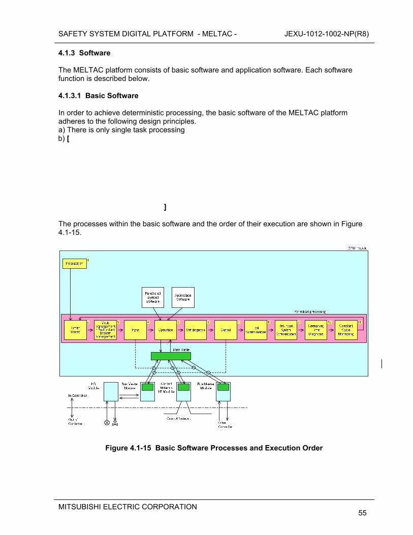
SAFETY SYSTEM DIGITAL PLATFORM - MELTAC - JEXU-1012-1002-NP(R8)
MITSUBISHI ELECTRIC CORPORATION
55
4.1.3 Software The MELTAC platform consists of basic software and application software. Each software function is described below. 4.1.3.1 Basic Software In order to achieve deterministic processing, the basic software of the MELTAC platform adheres to the following design principles. a) There is only single task processing b) [
]
The processes within the basic software and the order of their execution are shown in Figure 4.1-15.
Figure 4.1-15 Basic Software Processes and Execution Order
SAFETY SYSTEM DIGITAL PLATFORM - MELTAC - JEXU-1012-1002-NP(R8)
MITSUBISHI ELECTRIC CORPORATION
56
The processing time from No.2 to No.8 is based on the application logic and the input/output signal quantity of each system. Since the controller operates cyclically, the processing time from No. 2 to No. 11 can be 100% of the application requirement (i.e. there is no application margin required for the system). However, to allow future system expansion, during the system design phase, the approximate processing time from No.2 to No.8 is calculated as described in Section 4.4 Response Time. If the processing time exceeds about 80% of the processing cycle required for the system, the application is divided into two or more controllers, as necessary. In the test phase, the system response time is confirmed by measurement. The processes of the MELTAC basic software are described below. [

SAFETY SYSTEM DIGITAL PLATFORM - MELTAC - JEXU-1012-1002-NP(R8)
MITSUBISHI ELECTRIC CORPORATION
57
]
SAFETY SYSTEM DIGITAL PLATFORM - MELTAC - JEXU-1012-1002-NP(R8)
MITSUBISHI ELECTRIC CORPORATION
58
Figure 4.1-16 Remaining Time Diagnosis
[
]
SAFETY SYSTEM DIGITAL PLATFORM - MELTAC - JEXU-1012-1002-NP(R8)
MITSUBISHI ELECTRIC CORPORATION
59
4.1.3.2 Application Software The application software of the MELTAC platform is designed using the MELTAC engineering tool. Application software for functional algorithms is designed by combining simple graphical logic symbols such as “And”, “Or”, and ”Not” using the Graphical User Interface (GUI) of the MELTAC engineering tool. A GUI is used to reduce the potential for design errors in building or modifying the application software. It also makes it easier for the Independent Verifier to ensure the application software Graphical Block Diagrams (GBD), which are created by the I&C system designer are consistent with the Functional Block Diagrams (FBD), which are created by the process system designer. Using the MELTAC engineering tool, the application software GBD is automatically converted into Execution Data that is executed directly by the Operation process of the basic software. The Operation process of the basic software executes the Functional Symbol Software sequentially according to the Execution Data. Application software execution data is stored in the F-ROM of the CPU Module. [
] The Functional Symbols are listed in Appendix B.
SAFETY SYSTEM DIGITAL PLATFORM - MELTAC - JEXU-1012-1002-NP(R8)
MITSUBISHI ELECTRIC CORPORATION
60
4.1.4 MELTAC Engineering Tool The MELTAC engineering tool (called “MELENS”) provides various functions aimed at steadier and more efficient software management during all system life cycle phases (including design, fabrication, test, adjustment and maintenance). MELENS is installed on a non-safety Personal Computer running the Microsoft Windows Operating System. Access to MELENS is controlled by means of the PC password (BIOS, OS) and the MELENS password. The application software execution data generated by MELENS is downloaded to the controller via the Maintenance Network and is stored in the F-ROM of the CPU Module. The functions of MELENS are described as follows. 4.1.4.1 Function Description The functions of MELENS are as follows. a) Creation of Application Software The application software Graphical Block Diagram (GBD) is created from the Functional Block Diagrams (FBD) which is created with a commercial MITSUBISHI-made CAD software package called "RAPID". (Access to RAPID is controlled by a password.) MELENS can automatically translate the RAPID FBD to the MELTAC GBD. MELENS can then automatically generate the application software execution data directly from the GBD by compiling. This automated process eliminates human translation errors. GBDs can also be created manually using the MELENS GUI editor. Whether the GBD is generated automatically from RAPID or manually using the MELENS GUI, the assignment of GBDs to controllers and the assignment of Input/Output signals are configured manually using MELENS. b) Download New application software, including logic changes or changes to setpoints or constants, can be downloaded to the Controllers from the MELTAC engineering tool PC via the Maintenance Network. [
] c) Verifying F-ROM data The MELTAC engineering tool provides a manually initiated function which automatically compares the F-ROM for basic software and for application software data in the Controller, bit by bit, with the basic software data and application software data stored in MELENS. This
SAFETY SYSTEM DIGITAL PLATFORM - MELTAC - JEXU-1012-1002-NP(R8)
MITSUBISHI ELECTRIC CORPORATION
61
function is used during periodic surveillance tests to confirm that the data in F-ROMs is the same as the data in MELENS, and therefore has not changed. d) Controller failure diagnosis display The MELTAC engineering tool displays the self-diagnostic result of the Controllers. It shows which module(s) is failed. e) Temporary changes to field changeable process value in data table (Data Set) [
]
SAFETY SYSTEM DIGITAL PLATFORM - MELTAC - JEXU-1012-1002-NP(R8)
MITSUBISHI ELECTRIC CORPORATION
62
4.1.4.2 Network for MELTAC Engineering Tool In order to communicate between the MELTAC engineering tool and the Controller, the Maintenance Network is used. The MELTAC engineering tool, which runs on a Personal Computer, is temporarily connected via the Maintenance Network to the System Management Modules of each Controller in the division. This interface allows all functions described above. The Maintenance Network is temporarily connected to the controllers in the same safety division. There is a separate Maintenance Network for each division. There are no Maintenance Network interconnections between safety divisions. There is also a separate MELTAC engineering tool for each division. The specification of the Maintenance Network is described below. For the configuration and the isolation of the Maintenance Network, see Section 4.3.4. (Specification) Function: Transmission of maintenance date for MELTAC engineering tools Transmission protocol: Ethernet (IEEE Std. 802.3; CSMA / CD, UDP/IP) Transmission speed: 10Mbps Communication form: Dialog communication Connection form: Bus/Star-type
Transmission media: UTP Category5 cable [
]
SAFETY SYSTEM DIGITAL PLATFORM - MELTAC - JEXU-1012-1002-NP(R8)
MITSUBISHI ELECTRIC CORPORATION
63
4.1.5 Self-Diagnosis The MELTAC platform controller is equipped with three types of self-diagnosis features: a hardware based detection process, a software based detection process, and a combination thereof. When an error is detected, an alarm is generated. When the error is severe, the Controller makes a transition from the Control or Standby mode to the Failure mode. Detailed error descriptions are provided in Sections 4.1.5.2 thru 4.1.5.6. The categorization of each error is shown in parenthesis, for example “Clock check (Failure)”. All errors in Section 4.1.5.2 and 4.1.5.3 are severe and are therefore categorized as “Failure”. These errors stop main CPU operation, and generate signals that can be used for alarms. All other errors (those identified in Sections 4.1.5.4 and 4.1.5.5) generate signals that can be used for alarms, but do not stop the main CPU operation. All error signals are identified on the MELTAC engineering tool. The specific grouping of error signals into operator alarms is application specific. Since most applications have redundant CPUs, typically all error signals are grouped to a single operator alarm and then the MELTAC engineering tool is used for diagnosis of specific error conditions. Failure notice is provided to the plant monitoring system for the three types of errors, ”Failure”, “Alarm”, and “IO Alarm”. These error signals are typically grouped into system trouble alarms, however the method used to present this information to the operator from the plant monitoring system is application dependent and not within the scope of the MELTAC platform. Detail information for diagnosis of all error conditions is provided on the MELTAC engineering tool. a) Hardware based detection process With this feature, self-diagnosis is implemented by special diagnostic circuitry on the CPU Module. The feature involves a watchdog timer, parity error, timeout, analog input check, etc. b) Software based detection process With this feature, self-diagnosis is implemented using software. The feature involves CPU healthy check, ROM error check, RAM error check, etc. c) Software/hardware combination With this feature, circuitry that supports self-diagnosis is added to the Controller and self-diagnosis is performed using software-based read/write operations. This feature involves a digital input check, digital/analog output read-back check, etc. The controller is monitored based on the above self-diagnosis processes every Execution Cycle. The individual error items can be identified by viewing the LED display on the front of each module and the representative alarm display (Failure, Alarm, I/O Alarm) on the Status Display & Switch Module and by using the MELTAC engineering tool connected via the Maintenance Network.
SAFETY SYSTEM DIGITAL PLATFORM - MELTAC - JEXU-1012-1002-NP(R8)
MITSUBISHI ELECTRIC CORPORATION
64
Each detected error is categorized into the three types (Failure, Alarm and I/O Alarm) as below. 1) Failure The fatal abnormality by which the Subsystem cannot continue its functions is categorized as the Failure. When the Subsystem detects this type of error, it transits to the Failure mode. In the Failure mode, the processing of input/output and operation are stopped, although the processing of sending the own status data of the Failure mode is continued. In case of redundant standby controller configuration, when the Subsystem in the Control mode changes to the Failure Mode and the Subsystem in the Standby mode changes from the Standby Mode to the Control Mode and continues the control function. When there is no Subsystem which communicates with the Output Module, the Output Module transits to the Failure mode which is “as-is mode” or ”off mode”. This mode is set preliminarily. 2) Alarm The minor abnormality with which the Subsystem can continue its functions is categorized as the Alarm. This includes the error of the Controller Cabinet. When the Subsystem detects this type of error, it does not change its mode and only warns of the alarm. 3) I/O Alarm The abnormality of I/O is categorized as the I/O Alarm. When the Subsystem detects this type of error, it does not change its mode and only warns of the alarm. In case of redundant standby controller configuration, when the I/O Alarm occurs in the Redundant I/O in the Control Mode, the Subsystem stops to use this I/O, switches the other I/O from the Standby mode to the Control Mode, and continues the processing of input/output. When the I/O Alarm occurs in the Single Input Module, the last good input values are retained and the application software is informed of the abnormal state of the input signals. For digital inputs, the input values are kept at the last value (1 or 0) before the error occurred. For analog inputs, the input values are kept at the last engineering value before the error occurred. Based on the error flag, the application software can be programmed for a predetermined control action.
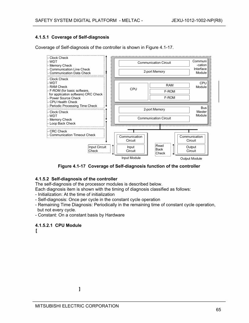
SAFETY SYSTEM DIGITAL PLATFORM - MELTAC - JEXU-1012-1002-NP(R8)
MITSUBISHI ELECTRIC CORPORATION
65
4.1.5.1 Coverage of Self-diagnosis Coverage of Self-diagnosis of the controller is shown in Figure 4.1-17.
Input Module
Input Circuit
Communication Circuit
Input Circuit Check
- CRC Check - Communication Timeout Check
Read Back Check
Output Module
- Clock Check - WDT - Memory Check - Loop Back Check
BusMasterModule
CPU Module
Communi-cation
Interface Module
- Clock Check - WDT - RAM Check - F-ROM (for basic software, for application software) CRC Check
- Power Source Check - CPU Health Check - Periodic Processing Time Check
2-port Memory
Communication Circuit
- Clock Check - WDT - Memory Check - Communication Line Check - Communication Data Check
CPU
F-ROM
RAM
F-ROM
Output Circuit
CommunicationCircuit
2-port Memory
Communication Circuit
Figure 4.1-17 Coverage of Self-diagnosis function of the controller
4.1.5.2 Self-diagnosis of the controller The self-diagnosis of the processor modules is described below. Each diagnosis item is shown with the timing of diagnosis classified as follows: - Initialization: At the time of initialization - Self-diagnosis: Once per cycle in the constant cycle operation - Remaining Time Diagnosis: Periodically in the remaining time of constant cycle operation, but not every cycle.
- Constant: On a constant basis by Hardware 4.1.5.2.1 CPU Module [
]

SAFETY SYSTEM DIGITAL PLATFORM - MELTAC - JEXU-1012-1002-NP(R8)
MITSUBISHI ELECTRIC CORPORATION
66
[
SAFETY SYSTEM DIGITAL PLATFORM - MELTAC - JEXU-1012-1002-NP(R8)
MITSUBISHI ELECTRIC CORPORATION
67
]
4.1.5.2.2 Bus Master Module [

SAFETY SYSTEM DIGITAL PLATFORM - MELTAC - JEXU-1012-1002-NP(R8)
MITSUBISHI ELECTRIC CORPORATION
68
]
SAFETY SYSTEM DIGITAL PLATFORM - MELTAC - JEXU-1012-1002-NP(R8)
MITSUBISHI ELECTRIC CORPORATION
69
4.1.5.3 Self Diagnosis of Power Supply Modules in the CPU Chassis [
] 4.1.5.4 Self-diagnosis of the Communication System See Section 4.3.2.4 and 4.3.3.4. Communication System errors are categorized as “Failure” or “Alarm”, depending on the redundancy configuration of the controller. 4.1.5.5 Self-diagnosis of I/O Modules The self-diagnosis the I/O modules is described below. 4.1.5.5.1 Input Module [
] 4.1.5.5.2 Output Module [
SAFETY SYSTEM DIGITAL PLATFORM - MELTAC - JEXU-1012-1002-NP(R8)
MITSUBISHI ELECTRIC CORPORATION
70
] 4.1.5.5.3 Controller Cabinet [
] 4.1.5.6 Operations when the hardware and software do not match Mismatch of the module configuration in the CPU chassis: The CPU Module detects the error and the subsystem turns to Failure mode. Mismatch of the module configuration in the I/O chassis: The CPU Module detects the mismatch and notifies the application software logic that the I/O signals have bad quality, as explained in Section 4.1.5. Currently, the subsystem does not transfer to Failure, Alarm, or I/O Alarm and does not give an alarm. However, the MELTAC basic software will be modified to add an I/O Alarm for this condition. This modification is being executed as a design change under the App.B QAP (see Section 6), because this I/O Alarm was not required by the original MELTAC specification. 4.1.6 Bus inside the controller Table 4.1-6 shows the two busses used inside the controller, and Table 4.1-7 shows I/O bus specification.

SAFETY SYSTEM DIGITAL PLATFORM - MELTAC - JEXU-1012-1002-NP(R8)
MITSUBISHI ELECTRIC CORPORATION
71
Table 4.1-6 Bus inside the controller
Item Application
Futurebus+ Backplane bus in the CPU chassis. It is used to connect modules in CPU chassis and transfers other module data in the CPU chassis.
I/O bus A bus that connects the CPU chassis and the I/O module. See Table 4.1-7 for detail.
Table 4.1-7 I/O bus specification
Item Specification Protocol 1:N master poling
Configuration
Maximum 96 I/O modules can be connected to one I/O bus. (Up to 16 I/O modules can be mounted on one I/O chassis and up to six chassis can be connected to one I/O bus.). There are four I/O busses on each Bus Master Module and each controller can have eight Bus Master Modules.
Interface RS-485 transformer isolation.
Baud rate 1Mbps
Error detection method CRC check
Operation
The Bus Master Module and the I/O modules are connected to the I/O bus. The Bus Master Module sends output data and input data requests to the I/O module and the I/O module responds to that. This communication method is common to all I/O modules, including the PIF module.
4.1.7 Manual test 4.1.7.1 Process input and output Figure 4.1-18 shows the signal flow of Manual test for process input and output. Input function is tested by manipulating the process to stimulate a state change. Correct functionality is confirmed by monitoring states signals on the safety VDU or any other VDU that obtains its status information from the Control Network (eg. non-safety operational VDU in PCMS) Output function is tested by operation from the safety VDU or any other VDU interfaced via the Control Network (eg. non-safety operational VDU in PCMS). It is noted that these tests are intended to confirm functionality of the system’s process input and output signal paths, since these cannot be fully tested by self-diagnostics. Therefore, the process input and output tests can be conducted using any VDU that obtains its data from the Control Network. A separate manual test for the safety VDU is described in Section 4.2.4.
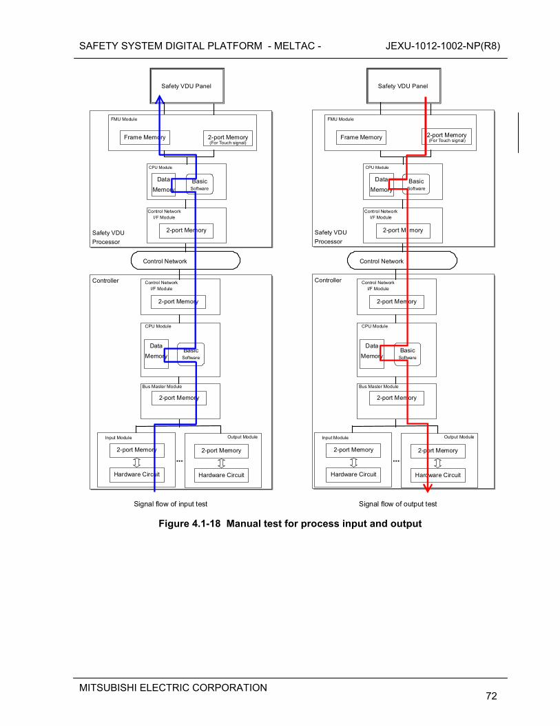
SAFETY SYSTEM DIGITAL PLATFORM - MELTAC - JEXU-1012-1002-NP(R8)
MITSUBISHI ELECTRIC CORPORATION
72
Safety VDU
Processor
Controller
2-port Memory
Hardware Circuit
2-port Memory
Input Module
Bus Master Module
CPU Module
2-port Memory
Hardware Circuit
Output Module
2-port Memory
Control Network I/F Module
Control Network
2-port Memory
Control Network I/F Module
FMU Module
Safety VDU Panel
Frame Memory 2-port Memory
CPU Module
Data
Memory Basic
Software
Data
Memory Basic
Software
2-port Memory
Hardware Circuit
2-port Memory
Input Module
Bus Master Module
CPU Module
2-port Memory
Hardware Circuit
Output Module
2-port Memory
Control Network I/F Module
Control Network
2-port M mory
Control Network I/F Module
FMU Module
Safety VDU Panel
Frame Memory 2-port Memory
CPU Module
Data
MemoryBasic
Software
Data
MemoryBasic
Software
Safety VDU
Processor
Controller
Signal flow of input test Signal flow of output test
(For Touch signal) (For Touch signal)
Figure 4.1-18 Manual test for process input and output
SAFETY SYSTEM DIGITAL PLATFORM - MELTAC - JEXU-1012-1002-NP(R8)
MITSUBISHI ELECTRIC CORPORATION
73
4.1.7.2 Software Memory Integrity The MELTAC engineering tool includes a manually initiated function which automatically compares the software memory in the controller, bit by bit, with a copy of the software stored off-line. This function is to confirm that the software in the controller is the same as the off-line version, and therefore has not changed or failed. This test confirms the functional integrity of the controller basic software and application software. The Software Memory Test is conducted periodically for every controller in the system. By confirming the basic software, the Software Memory Integrity test confirms the CPU instructions stored in F-ROM for all MELTAC functions described throughout this document, including the self-diagnostic functions. By confirming the application software, the Software Memory Integrity test confirms the CPU instructions stored in F-ROM for all functional logic required for the safety functions of the application. The periodic manual tests (the process input and output test, and the safety VDU test) ensure the CPU is capable of executing instructions from both F-ROM for basic software and F-ROM for application software. This encompasses the instructions that control continuous self-diagnostics, and the instructions that control the safety functions of monitoring process measurements and actuating plant components. Therefore, through the aggregate of periodic manual tests and continuous self-diagnostic tests, the complete functionality of the safety system is confirmed.
SAFETY SYSTEM DIGITAL PLATFORM - MELTAC - JEXU-1012-1002-NP(R8)
MITSUBISHI ELECTRIC CORPORATION
74
4.2 Safety VDU Panel and Processor The MELTAC platform includes a safety VDU which consists of a safety VDU panel, and a safety VDU processor. There is one safety VDU processor for each safety VDU panel. The number of safety VDUs is defined by specific plant design. Each safety VDU can be configured to provide the HSI for only one safety division. Each division has its own safety VDU. Since the total I&C system has 4-divisions, a single failure of only one safety VDU doesn’t cause loss of all HSI functions. 4.2.1 Hardware 4.2.1.1 Safety VDU Panel The safety VDU panel is an HSI device which provides a color graphic display with an integral touch screen. Its function is described below.
Display function: Displays operational screens by receiving red/green/blue (RGB) analog video signals from the safety VDU processor.
Control function: Inputs by operator on the touch screen are transmitted to the safety VDU processor in the form of x-y coordinate data using a RS-232C data link.
The complete HSI functional design, including screen navigation, is described in the HFE Process and HSI System Design Topical Report. Specifications of the safety VDU panel are in Appendix A.10.
SAFETY SYSTEM DIGITAL PLATFORM - MELTAC - JEXU-1012-1002-NP(R8)
MITSUBISHI ELECTRIC CORPORATION
75
4.2.1.2 Safety VDU Processor 4.2.1.2.1 Configuration of the Safety VDU Processor The safety VDU processor has a single Subsystem architecture as shown in Figure 4.2-1. The CPU Module and Control Network I/F Module hardware and basic software are the same as in the MELTAC Controller. a) Information Display Function The safety VDU processor stores the static data for each pre-configured display screen. The safety VDU processor gathers live plant data from safety Controllers via the Control Network. The safety VDU processor organizes the static data of the pre-configured screen with the live plant data and then displays those combined images on the safety VDU panel by means of the red/green/blue (RGB) interface. The RGB interface is generated by the Frame Memory Unit (FMU) Module. b) Control Function Operators take manual control actions by touching an operation switch image displayed on the safety VDU panel. A sample picture of the operation switch image is shown in Figure 4.2-5. The results of a touch screen operation are sent in the form of x-y coordinate data from the safety VDU panel to the safety VDU processor via the FMU Module. This is an RS-232C data link, which is converted from electrical to optical, only to increase the transmission distance. The safety VDU processor converts the x-y coordinate data received from the safety VDU panel to plant control data (i.e. component ID and operational command), and then sends the data to the Controllers via the Control Network. c) Control Network Interface The Control Network Interface receives live plant data from the Controllers, and sends the plant control data to the Controllers via the Control Network. The Control Network and safety VDU are both intra divisional.
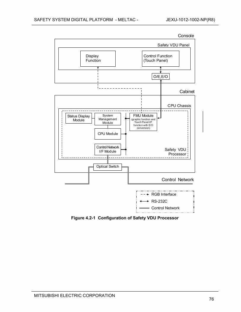
SAFETY SYSTEM DIGITAL PLATFORM - MELTAC - JEXU-1012-1002-NP(R8)
MITSUBISHI ELECTRIC CORPORATION
76
Display Function
Control Function (Touch Panel)
Safety VDU Panel
Console
Safety VDUProcessor
Control Network
System Management
Module
CPU Module
Control NetworkI/F Module
CPU Chassis
Status Display Module
RGB Interface
RS-232C
Control Network
Optical Switch
O/E,E/O
Cabinet
FMU Module(graphic function and
Touch Panel I/F function with E/O
conversion)
Figure 4.2-1 Configuration of Safety VDU Processor
SAFETY SYSTEM DIGITAL PLATFORM - MELTAC - JEXU-1012-1002-NP(R8)
MITSUBISHI ELECTRIC CORPORATION
77
4.2.1.2.2 Module Specifications of Safety VDU Processor The safety VDU processor is comprised of the following modules:
CPU Module System Management Module Control Network I/F Module Frame Memory Unit (FMU) Module Status Display Module
The FMU Modules are specific to the safety VDU processor. The other modules are the same hardware as the modules of the Controller. The following sections describe the modules that are specific to the safety VDU processor. a) FMU Module The FMU Module provides the analog RGB signal for the graphic images to the safety VDU panel. The FMU Module also provides the touch panel interface signal from the safety VDU panel to the safety VDU processor. The FMU Module communicates with the CPU Module inside the chassis by means of the Futurebus+ backplane. Specifications of the FMU Module are in Appendix A.11 4.2.1.3 Power Supply AC power can be supplied to the safety VDU with a single power supply configuration or a redundant configuration. The redundant configuration avoids loss of function due to a single failure in the power supply or the AC power source, as shown in Figure 4.2-2. The AC power is converted to DC voltage by the Power Supply Modules. For a redundant power supply configuration the DC power from both sources is diode auctioneered for each component of the safety VDU.
SAFETY SYSTEM DIGITAL PLATFORM - MELTAC - JEXU-1012-1002-NP(R8)
MITSUBISHI ELECTRIC CORPORATION
78
Figure 4.2-2 Configuration of Power Supply for Safety VDU
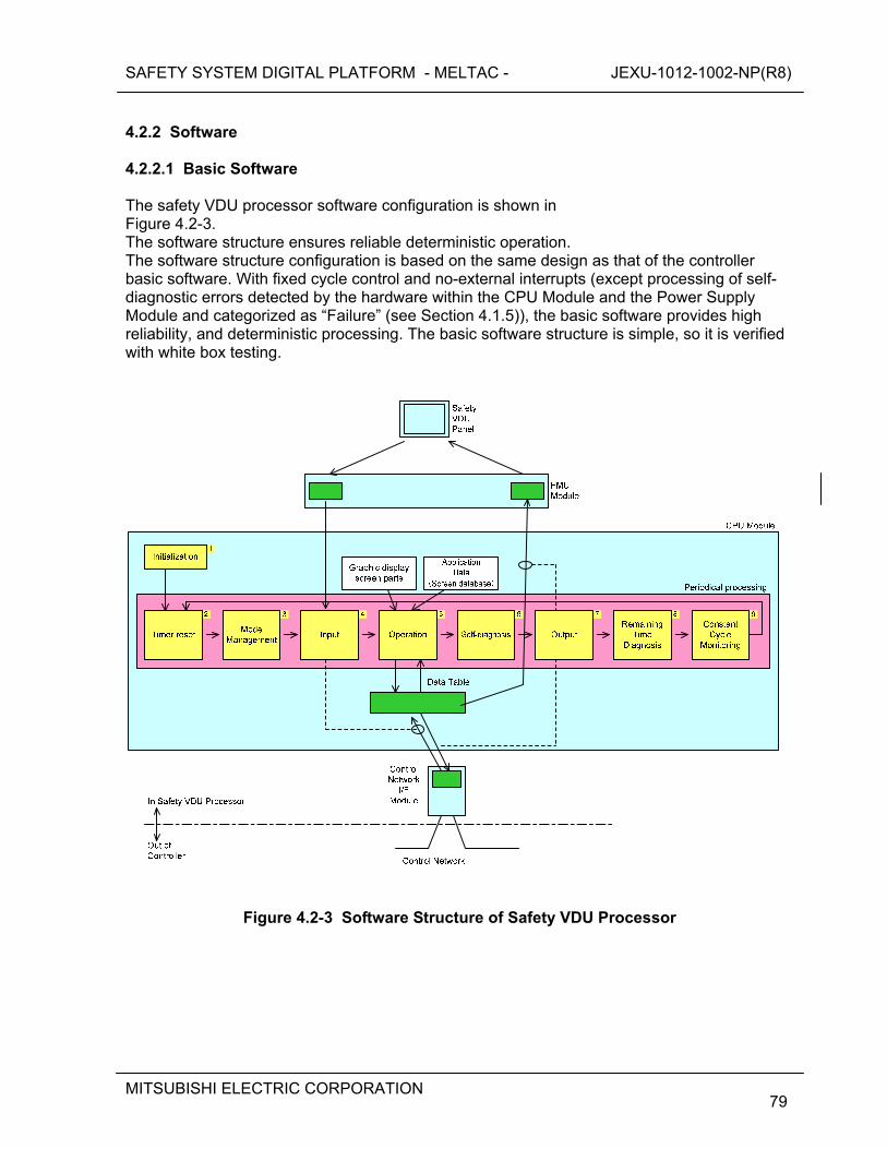
SAFETY SYSTEM DIGITAL PLATFORM - MELTAC - JEXU-1012-1002-NP(R8)
MITSUBISHI ELECTRIC CORPORATION
79
4.2.2 Software 4.2.2.1 Basic Software The safety VDU processor software configuration is shown in Figure 4.2-3. The software structure ensures reliable deterministic operation. The software structure configuration is based on the same design as that of the controller basic software. With fixed cycle control and no-external interrupts (except processing of self-diagnostic errors detected by the hardware within the CPU Module and the Power Supply Module and categorized as “Failure” (see Section 4.1.5)), the basic software provides high reliability, and deterministic processing. The basic software structure is simple, so it is verified with white box testing.
Figure 4.2-3 Software Structure of Safety VDU Processor
SAFETY SYSTEM DIGITAL PLATFORM - MELTAC - JEXU-1012-1002-NP(R8)
MITSUBISHI ELECTRIC CORPORATION
80
Details of the processing executed in each process are described below. [
]
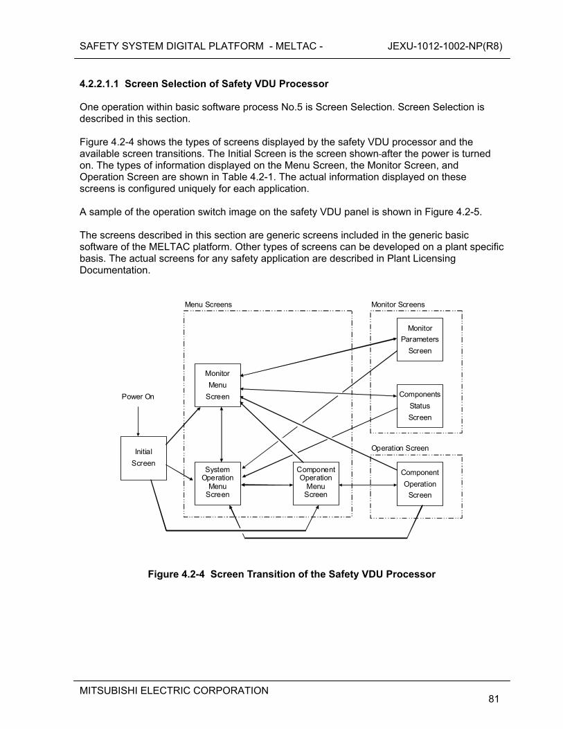
SAFETY SYSTEM DIGITAL PLATFORM - MELTAC - JEXU-1012-1002-NP(R8)
MITSUBISHI ELECTRIC CORPORATION
81
4.2.2.1.1 Screen Selection of Safety VDU Processor One operation within basic software process No.5 is Screen Selection. Screen Selection is described in this section. Figure 4.2-4 shows the types of screens displayed by the safety VDU processor and the available screen transitions. The Initial Screen is the screen shown after the power is turned on. The types of information displayed on the Menu Screen, the Monitor Screen, and Operation Screen are shown in Table 4.2-1. The actual information displayed on these screens is configured uniquely for each application. A sample of the operation switch image on the safety VDU panel is shown in Figure 4.2-5. The screens described in this section are generic screens included in the generic basic software of the MELTAC platform. Other types of screens can be developed on a plant specific basis. The actual screens for any safety application are described in Plant Licensing Documentation.
Monitor
Parameters
Screen
Components
Status
Screen
Component
Operation
Screen
ComponentOperation
Menu Screen
Monitor
Menu
Screen
System Operation
Menu Screen
Initial
Screen
Power On
Menu Screens Monitor Screens
Operation Screen
Figure 4.2-4 Screen Transition of the Safety VDU Processor

SAFETY SYSTEM DIGITAL PLATFORM - MELTAC - JEXU-1012-1002-NP(R8)
MITSUBISHI ELECTRIC CORPORATION
82
Table 4.2-1 Explanation of the Screen
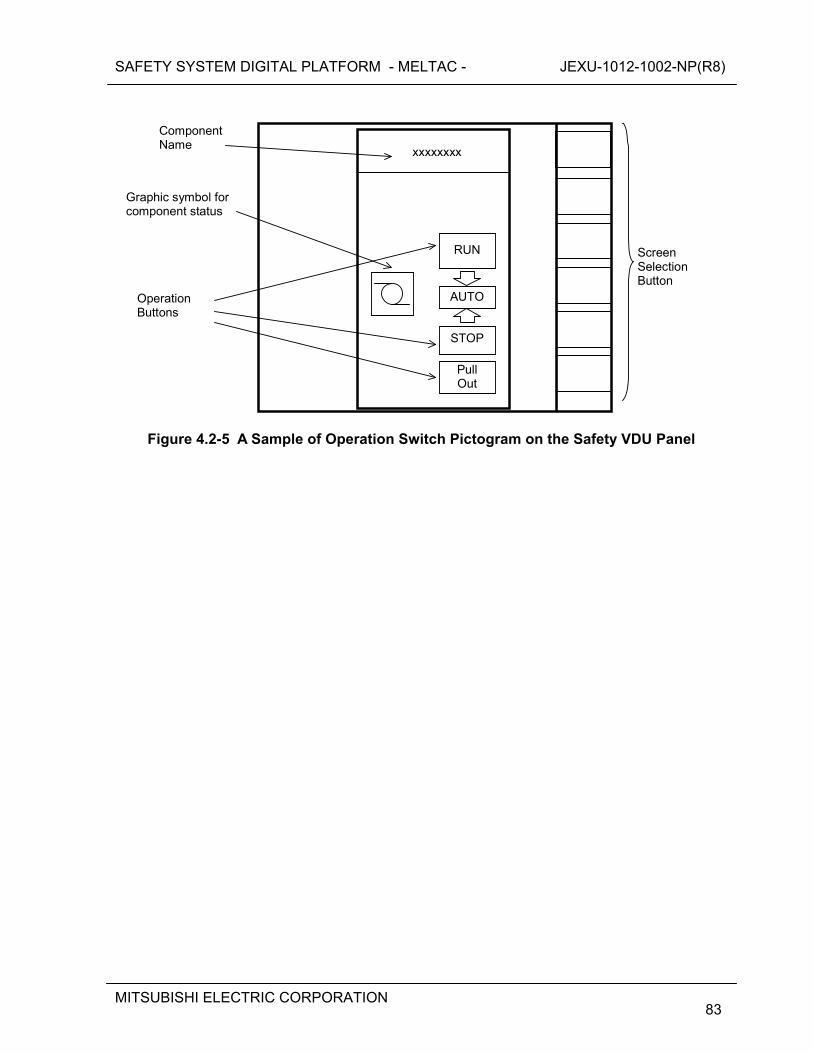
SAFETY SYSTEM DIGITAL PLATFORM - MELTAC - JEXU-1012-1002-NP(R8)
MITSUBISHI ELECTRIC CORPORATION
83
Pull Out
STOP
AUTO
RUN
Graphic symbol for component status
Operation Buttons
xxxxxxxx
Component Name
Screen Selection Button
Figure 4.2-5 A Sample of Operation Switch Pictogram on the Safety VDU Panel
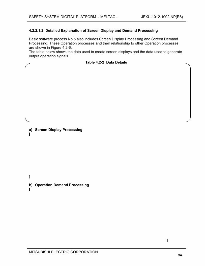
SAFETY SYSTEM DIGITAL PLATFORM - MELTAC - JEXU-1012-1002-NP(R8)
MITSUBISHI ELECTRIC CORPORATION
84
4.2.2.1.2 Detailed Explanation of Screen Display and Demand Processing Basic software process No.5 also includes Screen Display Processing and Screen Demand Processing. These Operation processes and their relationship to other Operation processes are shown in Figure 4.2-6. The table below shows the data used to create screen displays and the data used to generate output operation signals.
Table 4.2-2 Data Details
a) Screen Display Processing [
] b) Operation Demand Processing [
]
SAFETY SYSTEM DIGITAL PLATFORM - MELTAC - JEXU-1012-1002-NP(R8)
MITSUBISHI ELECTRIC CORPORATION
85
Figure 4.2-6 Explanation of the Safety VDU Processor Operation
SAFETY SYSTEM DIGITAL PLATFORM - MELTAC - JEXU-1012-1002-NP(R8)
MITSUBISHI ELECTRIC CORPORATION
86
4.2.2.2 Application Software and MELTAC Engineering Tool [
] 4.2.3 Self-Diagnosis [
SAFETY SYSTEM DIGITAL PLATFORM - MELTAC - JEXU-1012-1002-NP(R8)
MITSUBISHI ELECTRIC CORPORATION
87
] 4.2.4 Manual test The safety VDU panel is tested by manually touching screen targets and confirming correct safety VDU processor response. This test is conducted using a special test display screen that does not initiate any manual control actions. Many soft buttons are displayed throughout the special test display screen. The safety VDU panel sends the Operation Touch Signal to the safety VDU processor, when a button is touched. The safety VDU processor responds by changing the color of the touched button after receiving the signal. During this test, the safety VDU processor does not send any touch command control signals to the control network. These test response are generated by the safety VDU processor, so there is overlap between the manual test and the platform self-diagnostics performed within the safety VDU processor.
SAFETY SYSTEM DIGITAL PLATFORM - MELTAC - JEXU-1012-1002-NP(R8)
MITSUBISHI ELECTRIC CORPORATION
88
4.3 Communication System 4.3.1 General Description The key design basis of the Control Network, Data Link and Maintenance Network are provided below. a) Control Network and Data Link:
Asynchronous communications is used. Controller performs no communication handshaking that could disrupt deterministic logic processing.
Predefined data size and structure ensure deterministic communication. Communications independence – Electrical or communication processing faults in one
electrical division cannot adversely affect performance of the safety function in other divisions.
b) Maintenance Network:
Hardwired interlocks in the Controller or safety VDU processor ensure changes to software cannot be made through the data communication interface while the Controller or safety VDU processor are operating.
4.3.2 Control Network This section describes the Control Network. The Control Network communicates plant process data and control signal data with a deterministic periodic cycle. The Control Network is used for the following applications: a) The Control Network is used mainly to communicate safety related data between multiple
Controllers, and between Controllers and the safety VDU processor(s), all in the same train. b) The Control Network can also be used to communicate non-safety data between different
trains including the non-safety system. This may be between multiple Controllers in different s. Or it may be between operational VDU processors and multiple Controllers in different trains.
The specific inter-divisional communication data is application specific. The typical types of inter-divisional communication between safety and non-safety are as follows:
- Operation signal from non-safety operational VDUs to manually control the Safety components of each train
- Alarm or Status information from the Safety components or Safety instrumentation to Alarm VDUs, operational VDUs, or non-safety controllers.
- Signals from non-safety control systems that control safety related equipment during normal operation, such as signals from the pressurizer level and pressure control systems to control Charging Pumps and Backup Heaters.
Inter-divisional communication for safety related functions is not implemented in the Control Network. For this application only Data Link communication is used, see Section 4.3.3.
SAFETY SYSTEM DIGITAL PLATFORM - MELTAC - JEXU-1012-1002-NP(R8)
MITSUBISHI ELECTRIC CORPORATION
89
4.3.2.1 Configurations The Control Network has two types of periodic cycles, normal and high-speed. The desired type is selected during the application design process. The Configuration of the Control Network is as shown in Table 4.3-1.
Table 4.3-1 Configuration of Control Network
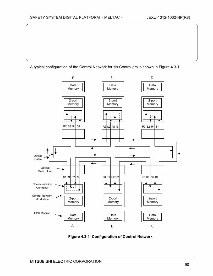
SAFETY SYSTEM DIGITAL PLATFORM - MELTAC - JEXU-1012-1002-NP(R8)
MITSUBISHI ELECTRIC CORPORATION
90
A typical configuration of the Control Network for six Controllers is shown in Figure 4.3-1.
Figure 4.3-1 Configuration of Control Network
Data Memory
2-port Memory
DataMemory
2-portMemory
Data Memory
2-port Memory
2-port Memory
Data Memory
2-portMemory
DataMemory
2-port Memory
Data Memory
F E D
C BA
Optical Cable
Optical Switch Unit
Communication Controller
Control Network I/F Module
CPU Module
R1 S2 R2 S1
S1 S2 R1 R2 S1 S2 R1 R2 S1 S2 R1 R2
R1 S2 R2 S1 R1 S2 R2 S1
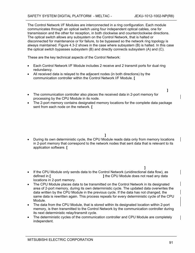
SAFETY SYSTEM DIGITAL PLATFORM - MELTAC - JEXU-1012-1002-NP(R8)
MITSUBISHI ELECTRIC CORPORATION
91
The Control Network I/F Modules are interconnected in a ring configuration. Each module communicates through an optical switch using four independent optical cables, one for transmission and the other for reception, in both clockwise and counterclockwise directions. The optical switch allows any subsystem on the Control Network, that is halted or disconnected for maintenance or for failure, to be bypassed so the network ring topology is always maintained. Figure 4.3-2 shows in the case where subsystem (B) is halted. In this case the optical switch bypasses subsystem (B) and directly connects subsystem (A) and (C). These are the key technical aspects of the Control Network: Each Control Network I/F Module includes 2 receive and 2 transmit ports for dual ring
redundancy. All received data is relayed to the adjacent nodes (in both directions) by the
communication controller within the Control Network I/F Module. [
]
The communication controller also places the received data in 2-port memory for processing by the CPU Module in its node.
The 2-port memory contains designated memory locations for the complete data package sent from each node on the network. [
] During its own deterministic cycle, the CPU Module reads data only from memory locations
in 2-port memory that correspond to the network nodes that sent data that is relevant to its application software. [
] If the CPU Module only sends data to the Control Network (unidirectional data flow), as
defined in [ ] the CPU Module does not read any data locations in 2-port memory.
The CPU Module places data to be transmitted on the Control Network in its designated area of 2-port memory, during its own deterministic cycle. The updated data overwrites the data written by the CPU Module in the previous cycle. If the data has not changed, the same data is rewritten again. This process repeats for every deterministic cycle of the CPU Module.
The data from the CPU Module, that is stored within its designated location within 2-port memory, is then transmitted to the Control Network by the communication controller during its next deterministic relay/transmit cycle.
The deterministic cycles of the communication controller and CPU Module are completely independent.

SAFETY SYSTEM DIGITAL PLATFORM - MELTAC - JEXU-1012-1002-NP(R8)
MITSUBISHI ELECTRIC CORPORATION
92
Figure 4.3-2 Explanation of Bypass Operation by the Optical Switch
The optical switch is powered by the power feeding cable from its associated Control Network I/F Module. If the MELTAC Controller fails, or its Control Network I/F Module fails, or the power feeding cable is disconnected, power is removed from the optical switch causing it to revert to the bypass mode for that node. When failures are detected by self-diagnostics, the Control Network I/F Module voluntarily removes power from the optical switch.
Data Memory
2-port Memory
DataMemory
2-portMemory
Data Memory
2-port Memory
2-port Memory
Data Memory
DataMemory
2-port Memory
Data Memory
F E D
C BA
Optical Cable
Optical Switch Unit
Communication Controller
Control Network I/F Module
CPU Module
R1 S2 R2 S1
S1 S2 R1 R2 S1 S2 R1 R2 S1 S2 R1 R2
R1 S2 R2 S1 R1 S2 R2 S1
Powerdown
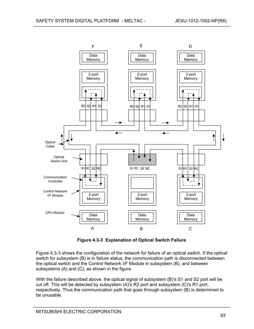
SAFETY SYSTEM DIGITAL PLATFORM - MELTAC - JEXU-1012-1002-NP(R8)
MITSUBISHI ELECTRIC CORPORATION
93
Figure 4.3-3 Explanation of Optical Switch Failure
Figure 4.3-3 shows the configuration of the network for failure of an optical switch. If the optical switch for subsystem (B) is in failure status, the communication path is disconnected between the optical switch and the Control Network I/F Module in subsystem (B), and between subsystems (A) and (C), as shown in the figure. With the failure described above, the optical signal of subsystem (B)'s S1 and S2 port will be cut off. This will be detected by subsystem (A)'s R2 port and subsystem (C)'s R1 port, respectively. Thus the communication path that goes through subsystem (B) is determined to be unusable.
Data Memory
2-port Memory
DataMemory
2-portMemory
Data Memory
2-port Memory
2-port Memory
Data Memory
2-portMemory
DataMemory
2-port Memory
Data Memory
F E D
C BA
Optical Cable
Optical Switch Unit
Communication Controller
Control Network I/F Module
CPU Module
R1 S2 R2 S1
S1 S2 R1 R2 S1 S2 R1 R2 S1 S2 R1 R2
R1 S2 R2 S1 R1 S2 R2 S1
SAFETY SYSTEM DIGITAL PLATFORM - MELTAC - JEXU-1012-1002-NP(R8)
MITSUBISHI ELECTRIC CORPORATION
94
A communication path between subsystems (A) and (C) will then be established automatically via subsystems (F)/(E)/(D). The same applies for communication from the other nodes that normally communicate through subsystem (B). Therefore, the only node that can no longer send or receive communication is subsystem (B). Send and receive communication between all other nodes remains fully operable. The reconfiguration of the communication paths described above causes a momentary disruption of data communication on the Control Network [ ]. However, since the optical switch has been qualified, failure of an optical switch is a random hardware failure, that can adversely affect the safety function of only one train, this momentary disruption is not considered in the normal Control Network response time. If the CPU Module reads the data in the Control Network I/F Module 2-port memory during this network reconfiguration disruption interval, the CPU Module will continue to use the data from the previous communication cycle. The CPU Module will alarm the network as failed if the data does not get updated after a predefined time.
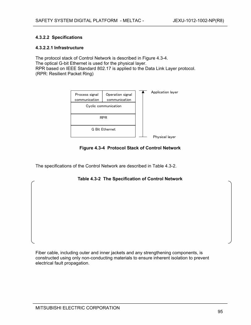
SAFETY SYSTEM DIGITAL PLATFORM - MELTAC - JEXU-1012-1002-NP(R8)
MITSUBISHI ELECTRIC CORPORATION
95
4.3.2.2 Specifications 4.3.2.2.1 Infrastructure The protocol stack of Control Network is described in Figure 4.3-4. The optical G-bit Ethernet is used for the physical layer. RPR based on IEEE Standard 802.17 is applied to the Data Link Layer protocol. (RPR: Resilient Packet Ring)
Process signal
communication
Cyclic communication
RPR
G Bit Ethernet
Physical layer
Application layer Operation signal
communication
Figure 4.3-4 Protocol Stack of Control Network
The specifications of the Control Network are described in Table 4.3-2.
Table 4.3-2 The Specification of Control Network
Fiber cable, including outer and inner jackets and any strengthening components, is constructed using only non-conducting materials to ensure inherent isolation to prevent electrical fault propagation.
SAFETY SYSTEM DIGITAL PLATFORM - MELTAC - JEXU-1012-1002-NP(R8)
MITSUBISHI ELECTRIC CORPORATION
96
4.3.2.2.2 Communication Method The data communication method of the Control Network is as follows. [
] The data is delivered to the destination Network I/F Module within the Guaranteed data update cycle time, shown in Table 4.3-1.

SAFETY SYSTEM DIGITAL PLATFORM - MELTAC - JEXU-1012-1002-NP(R8)
MITSUBISHI ELECTRIC CORPORATION
97
4.3.2.2.3 Communication Controller [
SAFETY SYSTEM DIGITAL PLATFORM - MELTAC - JEXU-1012-1002-NP(R8)
MITSUBISHI ELECTRIC CORPORATION
98
]
SAFETY SYSTEM DIGITAL PLATFORM - MELTAC - JEXU-1012-1002-NP(R8)
MITSUBISHI ELECTRIC CORPORATION
99
4.3.2.3 Isolation The MELTAC platform maintains electrical isolation and communication isolation for the interface between Controllers in separate safety trains and for the interface between safety Controllers and any non-safety train. The methodology to ensure this isolation is described below. a) Electrical Isolation The MELTAC platform uses fiber optics and optical to electrical converters (E/O Converter) to ensure electric Isolation. The optical communication circuit is shown in Figure 4.3-5 b) Communication Isolation [
]
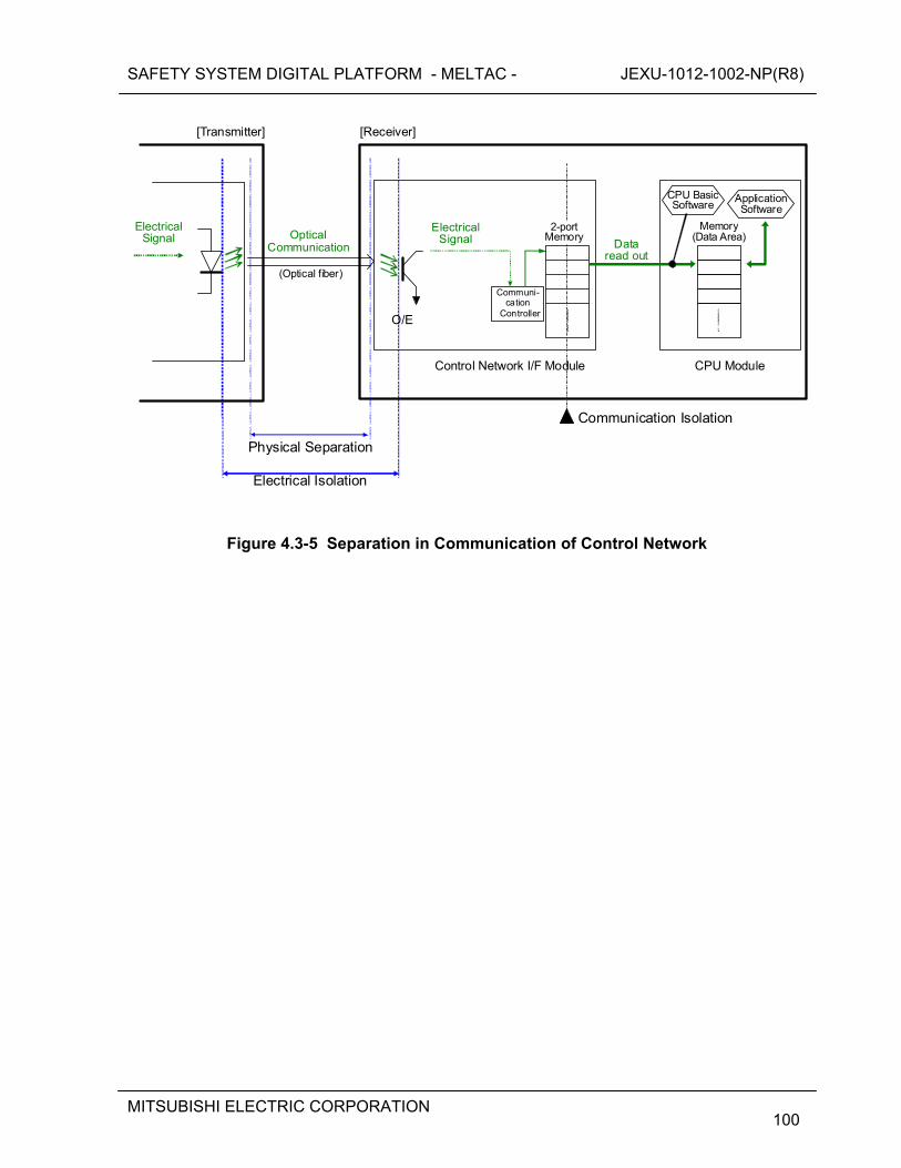
SAFETY SYSTEM DIGITAL PLATFORM - MELTAC - JEXU-1012-1002-NP(R8)
MITSUBISHI ELECTRIC CORPORATION
100
Electrical Isolation
(Optical fiber)
Optical Communication Data
read out
Electrical Signal
Application Software
Memory(Data Area)
Communi-cation
Controller
[Receiver]
Physical Separation
Communication Isolation
ElectricalSignal
CPU Basic Software
2-portMemory
CPU Module
[Transmitter]
Control Network I/F Module
O/E
Figure 4.3-5 Separation in Communication of Control Network
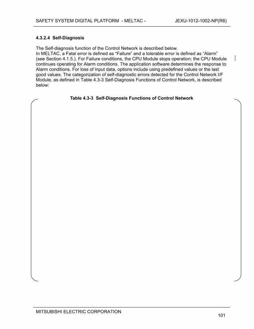
SAFETY SYSTEM DIGITAL PLATFORM - MELTAC - JEXU-1012-1002-NP(R8)
MITSUBISHI ELECTRIC CORPORATION
101
4.3.2.4 Self-Diagnosis The Self-diagnosis function of the Control Network is described below. In MELTAC, a Fatal error is defined as “Failure” and a tolerable error is defined as “Alarm” (see Section 4.1.5.). For Failure conditions, the CPU Module stops operation; the CPU Module continues operating for Alarm conditions. The application software determines the response to Alarm conditions. For loss of input data, options include using predefined values or the last good values. The categorization of self-diagnostic errors detected for the Control Network I/F Module, as defined in Table 4.3-3 Self-Diagnosis Functions of Control Network, is described below:
Table 4.3-3 Self-Diagnosis Functions of Control Network
SAFETY SYSTEM DIGITAL PLATFORM - MELTAC - JEXU-1012-1002-NP(R8)
MITSUBISHI ELECTRIC CORPORATION
102
SAFETY SYSTEM DIGITAL PLATFORM - MELTAC - JEXU-1012-1002-NP(R8)
MITSUBISHI ELECTRIC CORPORATION
103
4.3.2.5 Communication Independence This section describes how communication independence is maintained when the Control Network is applied for data communication between non-safety system and safety systems. This section provides details for communication isolation, which is described in Section 4.3.2.3. To exemplify this independence, this section describes the operational signal interface from the non-safety operational VDU (O-VDU) to the safety controller via the Unit Bus, and the monitoring signal interface from the Reactor Protection System (RPS) to the O-VDU via the Unit Bus, as applied in the US-APWR. The O-VDU interface is an example to show the receiving process from non-safety system to the safety system and RPS interface is an example to show the sending process from safety system to non-safety system. Figure 4.3-6 and Figure 4.3-7 show the relevant portion of the US-APWR system. (See MUAP-07004 for the entire configuration of the US-APWR system.) [
]
Figure 4.3-6 Operation signal flow from O-VDU
SAFETY SYSTEM DIGITAL PLATFORM - MELTAC - JEXU-1012-1002-NP(R8)
MITSUBISHI ELECTRIC CORPORATION
104
Figure 4.3-7 Process signal flow from RPS to Unit Bus
SAFETY SYSTEM DIGITAL PLATFORM - MELTAC - JEXU-1012-1002-NP(R8)
MITSUBISHI ELECTRIC CORPORATION
105
4.3.2.5.1 Detail data flow This section describes the detail data flow between the Control Network I/F Module and the CPU Module in the COM. [
]
Figure 4.3-8 Detail signal flow in COM (Receiving process)
[
SAFETY SYSTEM DIGITAL PLATFORM - MELTAC - JEXU-1012-1002-NP(R8)
MITSUBISHI ELECTRIC CORPORATION
106
]
Figure 4.3-9 Detail signal flow in RPS (Sending process)
[

SAFETY SYSTEM DIGITAL PLATFORM - MELTAC - JEXU-1012-1002-NP(R8)
MITSUBISHI ELECTRIC CORPORATION
107
]
SAFETY SYSTEM DIGITAL PLATFORM - MELTAC - JEXU-1012-1002-NP(R8)
MITSUBISHI ELECTRIC CORPORATION
108
(1) Receiving process (1-1) Processing by the Control Network I/F Module
This paragraph discusses the processing in the Control Network I/F Module. Figure 4.3-10 provides details of the Figure 4.3-8.
Figure 4.3-10 Processing by the Control Network I/F Module
[

SAFETY SYSTEM DIGITAL PLATFORM - MELTAC - JEXU-1012-1002-NP(R8)
MITSUBISHI ELECTRIC CORPORATION
109
]
SAFETY SYSTEM DIGITAL PLATFORM - MELTAC - JEXU-1012-1002-NP(R8)
MITSUBISHI ELECTRIC CORPORATION
110
(1-2) Processing by the CPU Module
This paragraph explains the processing of the data by the CPU Module. Figure 4.3-11 provides details of the Figure 4.3-8.
Figure 4.3-11 Processing by the CPU Module
SAFETY SYSTEM DIGITAL PLATFORM - MELTAC - JEXU-1012-1002-NP(R8)
MITSUBISHI ELECTRIC CORPORATION
111
[

SAFETY SYSTEM DIGITAL PLATFORM - MELTAC - JEXU-1012-1002-NP(R8)
MITSUBISHI ELECTRIC CORPORATION
112
]
SAFETY SYSTEM DIGITAL PLATFORM - MELTAC - JEXU-1012-1002-NP(R8)
MITSUBISHI ELECTRIC CORPORATION
113
(2) Sending Process (2-1) Processing by the CPU Module
Figure 4.3-12 provides details of the Figure 4.3-9. And this paragraph explains the processing by the CPU Module.
Figure 4.3-12 Processing by the CPU Module
SAFETY SYSTEM DIGITAL PLATFORM - MELTAC - JEXU-1012-1002-NP(R8)
MITSUBISHI ELECTRIC CORPORATION
114
[
]
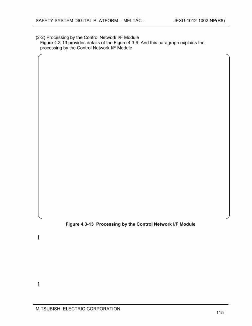
SAFETY SYSTEM DIGITAL PLATFORM - MELTAC - JEXU-1012-1002-NP(R8)
MITSUBISHI ELECTRIC CORPORATION
115
(2-2) Processing by the Control Network I/F Module
Figure 4.3-13 provides details of the Figure 4.3-9. And this paragraph explains the processing by the Control Network I/F Module.
Figure 4.3-13 Processing by the Control Network I/F Module
[
]
SAFETY SYSTEM DIGITAL PLATFORM - MELTAC - JEXU-1012-1002-NP(R8)
MITSUBISHI ELECTRIC CORPORATION
116
4.3.2.5.2 Summary of the design feature for the interdivisional communication This section discusses the summary of the design feature for the interdivisional communication on the Control Network. The receiving process in the data flow from the O-VDU to the COM will be discussed in this section. In the Control Network interface, there are design policies and network check methods that provide the necessary means to comply with the requirements of ISG-04 for communication. [
SAFETY SYSTEM DIGITAL PLATFORM - MELTAC - JEXU-1012-1002-NP(R8)
MITSUBISHI ELECTRIC CORPORATION
117
]
SAFETY SYSTEM DIGITAL PLATFORM - MELTAC - JEXU-1012-1002-NP(R8)
MITSUBISHI ELECTRIC CORPORATION
118
[
] (4) Conformance summary to ISG-04
The conformance of ISG-04 is shown in MELTAC platform ISG-04 Conformance Analysis (JEXU-1015-1009) and Appendix D of this technical report.
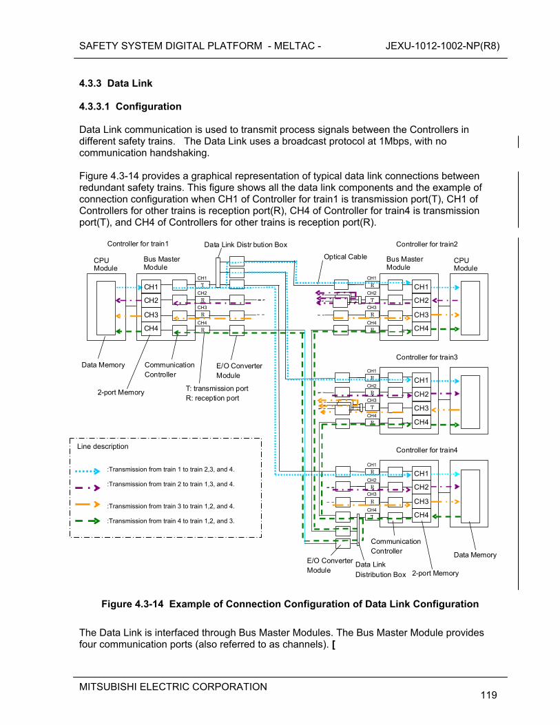
SAFETY SYSTEM DIGITAL PLATFORM - MELTAC - JEXU-1012-1002-NP(R8)
MITSUBISHI ELECTRIC CORPORATION
119
4.3.3 Data Link 4.3.3.1 Configuration Data Link communication is used to transmit process signals between the Controllers in different safety trains. The Data Link uses a broadcast protocol at 1Mbps, with no communication handshaking. Figure 4.3-14 provides a graphical representation of typical data link connections between redundant safety trains. This figure shows all the data link components and the example of connection configuration when CH1 of Controller for train1 is transmission port(T), CH1 of Controllers for other trains is reception port(R), CH4 of Controller for train4 is transmission port(T), and CH4 of Controllers for other trains is reception port(R).
CH1
CH2
CH3
CH4
Controller for train1
2-port Memory
Communication Controller
Data Link Distr bution Box
Data Memory
CPU Module
Bus Master Module
CH1
CH2
CH3
CH4
Bus Master Module
CPU Module
Controller for train2
CH1
CH2
CH3
CH4
Controller for train3
CH1
CH2
CH3
CH4
Controller for train4
T CH1
R CH2
R CH3
R CH4
RCH1
TCH2
RCH3
RCH4
RCH1
RCH2
TCH3
RCH4
RCH1
RCH2
RCH3
TCH4
T: transmission port R: reception port
Optical Cable
Data Memory
2-port Memory
Communication Controller
E/O Converter Module
E/O Converter Module
Data Link
Distribution Box
Figure 4.3-14 Example of Connection Configuration of Data Link Configuration
The Data Link is interfaced through Bus Master Modules. The Bus Master Module provides four communication ports (also referred to as channels). [
Line description
:Transmission from train 1 to train 2,3, and 4. :Transmission from train 2 to train 1,3, and 4. :Transmission from train 3 to train 1,2, and 4. :Transmission from train 4 to train 1,2, and 3.
SAFETY SYSTEM DIGITAL PLATFORM - MELTAC - JEXU-1012-1002-NP(R8)
MITSUBISHI ELECTRIC CORPORATION
120
]
Each port is set either as a transmission port or a reception port. The Bus Master Module produces an electrical output. The output is divided into three signal lines by the Data Link Distribution Box; then each output is converted into an optical signal by the Electrical/Optical Converter Module. The transmission port of the Electrical/Optical Converter Module is connected by the optical cable to the reception port of the Electrical/Optical Converter Module in another train. [
]
SAFETY SYSTEM DIGITAL PLATFORM - MELTAC - JEXU-1012-1002-NP(R8)
MITSUBISHI ELECTRIC CORPORATION
121
4.3.3.2 Specifications 4.3.3.2.1 Infrastructure The specifications of the Data Link Communications are described in Table 4.3-4.
Table 4.3-4 The Specification of Data Link Communication
4.3.3.2.2 Communication Method [
]
SAFETY SYSTEM DIGITAL PLATFORM - MELTAC - JEXU-1012-1002-NP(R8)
MITSUBISHI ELECTRIC CORPORATION
122
4.3.3.2.3Communication Controller [
]
SAFETY SYSTEM DIGITAL PLATFORM - MELTAC - JEXU-1012-1002-NP(R8)
MITSUBISHI ELECTRIC CORPORATION
123
4.3.3.3 Isolation The isolation method is basically the same as for the Control Network. However the Data Link communication interface is implemented in the Bus Master Modules and the communication is unidirectional. The physical, electrical, and functional isolation, based on the above figure, is as described below. a) Physical Separation The E/O converter module of the data link allows for distance of 1Kmeters between sending and receiving controllers. This allows the controllers to be geographically separated into separate I&C equipment rooms. For example for the PSMS of the US-APWR, the configuration of controllers for each train is described in MUAP-07004. b) Electrical Isolation The MELTAC platform uses fiber optics and optical to electrical converters (E/O Converter) to ensure electric Isolation. The optical communication circuit is shown in Figure 4.3-15. c) Communication Isolation [
]
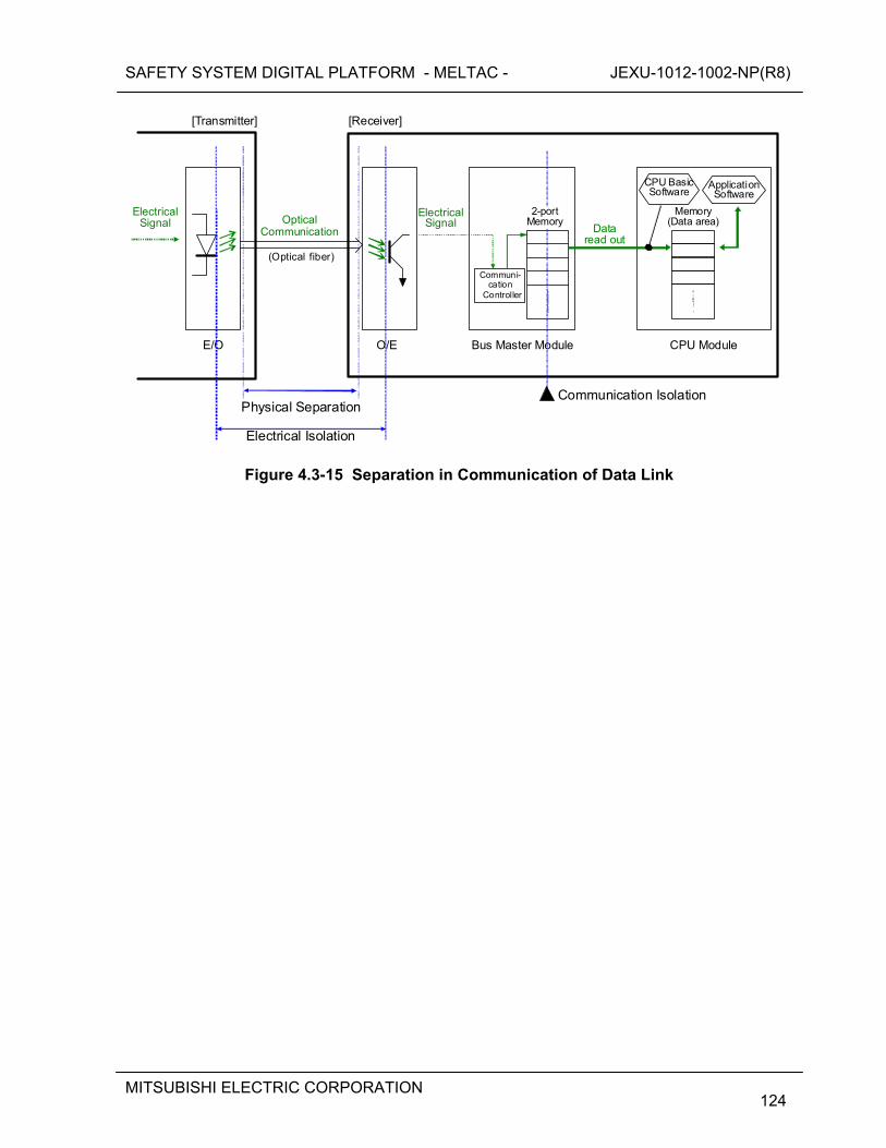
SAFETY SYSTEM DIGITAL PLATFORM - MELTAC - JEXU-1012-1002-NP(R8)
MITSUBISHI ELECTRIC CORPORATION
124
O/E
Electrical Isolation
E/O
(Optical fiber)
Optical Communication Data
read out
Electrical Signal
Application Software
Memory (Data area)
Communi-cation
Controller
[Receiver]
Physical Separation Communication Isolation
ElectricalSignal
CPU Basic Software
2-portMemory
CPU Module
[Transmitter]
Bus Master Module
Figure 4.3-15 Separation in Communication of Data Link
SAFETY SYSTEM DIGITAL PLATFORM - MELTAC - JEXU-1012-1002-NP(R8)
MITSUBISHI ELECTRIC CORPORATION
125
4.3.3.4 Self-Diagnosis The Self-diagnosis functions of the Data link are as follows. [
]
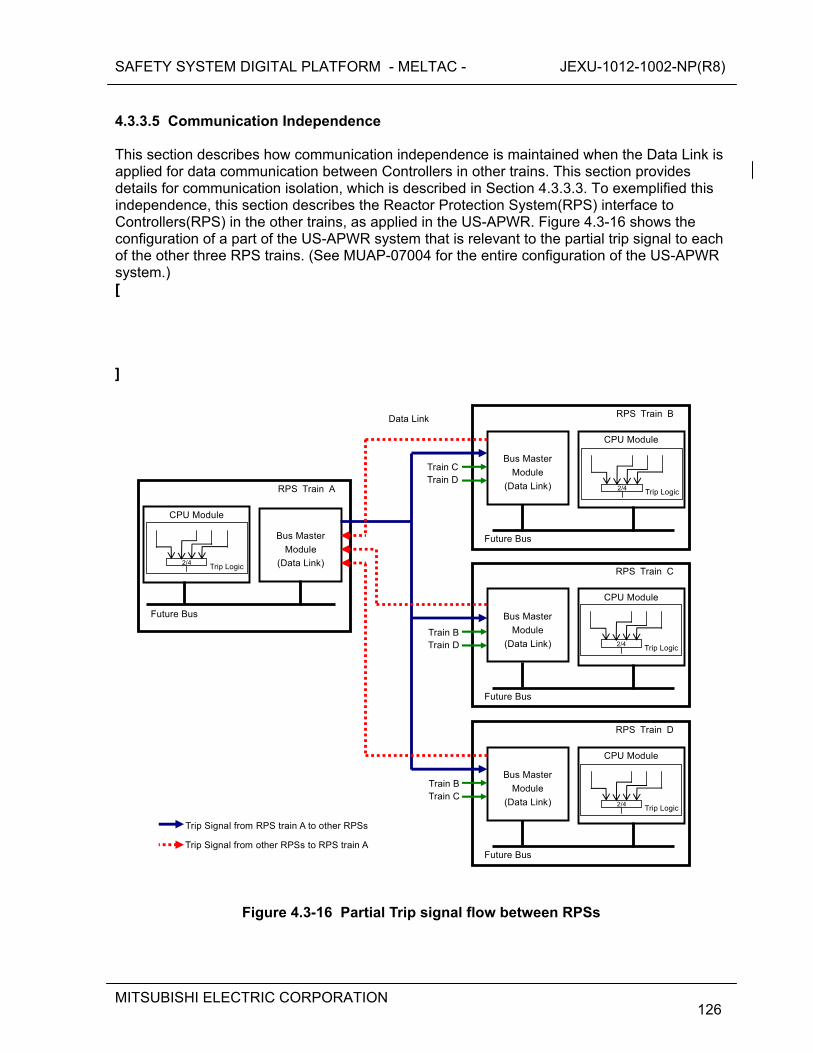
SAFETY SYSTEM DIGITAL PLATFORM - MELTAC - JEXU-1012-1002-NP(R8)
MITSUBISHI ELECTRIC CORPORATION
126
4.3.3.5 Communication Independence This section describes how communication independence is maintained when the Data Link is applied for data communication between Controllers in other trains. This section provides details for communication isolation, which is described in Section 4.3.3.3. To exemplified this independence, this section describes the Reactor Protection System(RPS) interface to Controllers(RPS) in the other trains, as applied in the US-APWR. Figure 4.3-16 shows the configuration of a part of the US-APWR system that is relevant to the partial trip signal to each of the other three RPS trains. (See MUAP-07004 for the entire configuration of the US-APWR system.) [
]
RPS Train B
CPU Module
Bus Master
Module
(Data Link)
Future Bus
RPS Train A
CPU Module
Bus Master
Module
(Data Link)
Future Bus
RPS Train C
CPU Module
Bus Master
Module
(Data Link)
Future Bus
RPS Train D
CPU Module
Bus Master
Module
(Data Link)
Future Bus
Train C Train D
Train B Train D
Train B Train C
Data Link
Trip Signal from RPS train A to other RPSs
Trip Signal from other RPSs to RPS train A
Trip Logic2/4
Trip Logic2/4
Trip Logic2/4
Trip Logic
2/4
Figure 4.3-16 Partial Trip signal flow between RPSs
SAFETY SYSTEM DIGITAL PLATFORM - MELTAC - JEXU-1012-1002-NP(R8)
MITSUBISHI ELECTRIC CORPORATION
127
4.3.3.5.1 Detail data flow This section describes the detail data flow between the Bus Master Module and the CPU Module in the RPS. [
]
Figure 4.3-17 Detail signal flow in RPS (Receiving process)
[
SAFETY SYSTEM DIGITAL PLATFORM - MELTAC - JEXU-1012-1002-NP(R8)
MITSUBISHI ELECTRIC CORPORATION
128
]
Figure 4.3-18 Detail signal flow in RPS (Sending process)
[
]
SAFETY SYSTEM DIGITAL PLATFORM - MELTAC - JEXU-1012-1002-NP(R8)
MITSUBISHI ELECTRIC CORPORATION
129
(1) Receiving Process (1-1) Processing by the Bus Master Module
Figure 4.3-19 provides details of the Figure 4.3-17. And this paragraph explains the processing by the Bus Master Module.
Figure 4.3-19 Processing by the Bus Master Module
[
SAFETY SYSTEM DIGITAL PLATFORM - MELTAC - JEXU-1012-1002-NP(R8)
MITSUBISHI ELECTRIC CORPORATION
130
] (1-2) Processing by the CPU Module
Figure 4.3-20 provides details of the Figure 4.3-17. And this paragraph explains the processing by the CPU Module.
Figure 4.3-20 Processing by the CPU Module
SAFETY SYSTEM DIGITAL PLATFORM - MELTAC - JEXU-1012-1002-NP(R8)
MITSUBISHI ELECTRIC CORPORATION
131
[
]
SAFETY SYSTEM DIGITAL PLATFORM - MELTAC - JEXU-1012-1002-NP(R8)
MITSUBISHI ELECTRIC CORPORATION
132
(2) Sending Process (2-1) Processing by the CPU Module
Figure 4.3-21 provides details of the Figure 4.3-18. And this paragraph explains the processing by the CPU Module.
Figure 4.3-21 Processing by the CPU Module

SAFETY SYSTEM DIGITAL PLATFORM - MELTAC - JEXU-1012-1002-NP(R8)
MITSUBISHI ELECTRIC CORPORATION
133
[
]
SAFETY SYSTEM DIGITAL PLATFORM - MELTAC - JEXU-1012-1002-NP(R8)
MITSUBISHI ELECTRIC CORPORATION
134
(2-2) Processing by the Bus Master Module
Figure 4.3-21 provides details of the Figure 4.3-18. And this paragraph explains the processing by the Bus Master Module.
Figure 4.3-22 Processing by the Bus Master Module
[
]
SAFETY SYSTEM DIGITAL PLATFORM - MELTAC - JEXU-1012-1002-NP(R8)
MITSUBISHI ELECTRIC CORPORATION
135
4.3.3.5.2 Summary of the design feature for the interdivisional communication This section discusses the summary of the design feature for the interdivisional communication on the Data Link. [
SAFETY SYSTEM DIGITAL PLATFORM - MELTAC - JEXU-1012-1002-NP(R8)
MITSUBISHI ELECTRIC CORPORATION
136
] (3) Conformance to ISG-04
The conformance of ISG-04 is shown in MELTAC platform ISG-04 Conformance Analysis (JEXU-1015-1009) and Appendix D of this technical report.
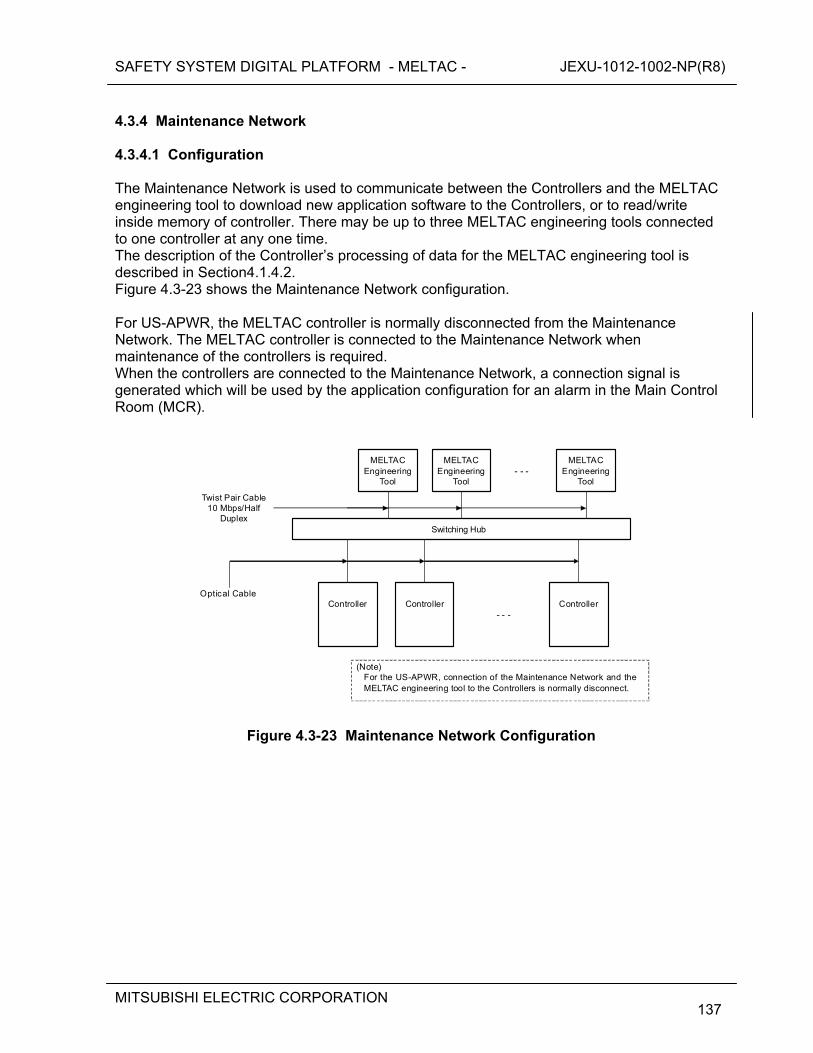
SAFETY SYSTEM DIGITAL PLATFORM - MELTAC - JEXU-1012-1002-NP(R8)
MITSUBISHI ELECTRIC CORPORATION
137
4.3.4 Maintenance Network 4.3.4.1 Configuration The Maintenance Network is used to communicate between the Controllers and the MELTAC engineering tool to download new application software to the Controllers, or to read/write inside memory of controller. There may be up to three MELTAC engineering tools connected to one controller at any one time. The description of the Controller’s processing of data for the MELTAC engineering tool is described in Section4.1.4.2. Figure 4.3-23 shows the Maintenance Network configuration. For US-APWR, the MELTAC controller is normally disconnected from the Maintenance Network. The MELTAC controller is connected to the Maintenance Network when maintenance of the controllers is required. When the controllers are connected to the Maintenance Network, a connection signal is generated which will be used by the application configuration for an alarm in the Main Control Room (MCR).
MELTAC
Engineering Tool
Switching Hub
ControllerController Controller - - -
Twist Pair Cable 10 Mbps/Half
Duplex
Optical Cable
MELTAC Engineering
Tool
MELTAC Engineering
Tool - - -
(Note) For the US-APWR, connection of the Maintenance Network and the MELTAC engineering tool to the Controllers is normally disconnect.
Figure 4.3-23 Maintenance Network Configuration
SAFETY SYSTEM DIGITAL PLATFORM - MELTAC - JEXU-1012-1002-NP(R8)
MITSUBISHI ELECTRIC CORPORATION
138
4.3.4.2 Isolation [

SAFETY SYSTEM DIGITAL PLATFORM - MELTAC - JEXU-1012-1002-NP(R8)
MITSUBISHI ELECTRIC CORPORATION
139
]
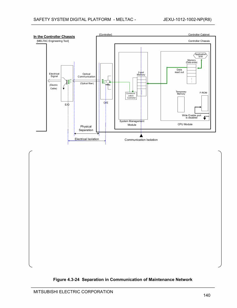
SAFETY SYSTEM DIGITAL PLATFORM - MELTAC - JEXU-1012-1002-NP(R8)
MITSUBISHI ELECTRIC CORPORATION
140
In the Controller Chassis
Electrical Isolation
Data read out
Application S/W
Memory(Data area)
Communi-cation
Controller
[Controller]
Physical Separation
Communication Isolation
2-portMemory
CPU Module
[MELTAC Engineering Tool]
System Management
Module
Temporary Memory F-ROM
O/E
(Optical fiber)
Optical Communication
E/O
Electrical Signal
(Electric
Cable)
Controller Cabinet
Controller Chassis
Write Enable portis disabled
Figure 4.3-24 Separation in Communication of Maintenance Network
SAFETY SYSTEM DIGITAL PLATFORM - MELTAC - JEXU-1012-1002-NP(R8)
MITSUBISHI ELECTRIC CORPORATION
141
Figure 4.3-25 Dedicated Re-programming Chassis for Writing F-ROM
SAFETY SYSTEM DIGITAL PLATFORM - MELTAC - JEXU-1012-1002-NP(R8)
MITSUBISHI ELECTRIC CORPORATION
142
The MELTAC engineering tool and Switching Hub are connected to the Controller based on the following design features:
The non-safety MELTAC engineering tool and Switching Hub are electrically isolated from the safety components through qualified fiber optic isolators with E/O converters.
The communication interface for each Controller uses a separate System Management Module with 2-port memory to ensure the communication process and safety function process execute asynchronously.
The controller is normally disconnected from the Maintenance Network, so there is no communication with the MELTAC engineering tool. However, when the controller is connected to the Maintenance Network, the following communication description applies:
When the Controllers are in service (ie. with the CPU Module in its normal configuration in the controller cabinet and with the write enable port of the F-ROM disabled) they provide only unidirectional outbound communication to the MELTAC engineering tool (ie. there is no ability for the MELTAC engineering tool to write information to the Controller’s memory) , based on data requests from the MELTAC engineering tool.
[
]
SAFETY SYSTEM DIGITAL PLATFORM - MELTAC - JEXU-1012-1002-NP(R8)
MITSUBISHI ELECTRIC CORPORATION
143
4.3.4.3 Design Basis of Connection to Maintenance Network [
]
SAFETY SYSTEM DIGITAL PLATFORM - MELTAC - JEXU-1012-1002-NP(R8)
MITSUBISHI ELECTRIC CORPORATION
144
4.3.4.4 Specifications 4.3.4.4.1 Infrastructure The specifications of the Maintenance Network Communication are described in Table 4.3-5.
Table 4.3-5 The Specification of Maintenance Network Communication
Fiber cable, including outer and inner jackets and any strengthening components, is constructed using only non-conducting materials to ensure inherent isolation to prevent electrical fault propagation. 4.3.4.4.2 Communication Method [
]

SAFETY SYSTEM DIGITAL PLATFORM - MELTAC - JEXU-1012-1002-NP(R8)
MITSUBISHI ELECTRIC CORPORATION
145
4.3.4.4.3 Communication Controller [
]
SAFETY SYSTEM DIGITAL PLATFORM - MELTAC - JEXU-1012-1002-NP(R8)
MITSUBISHI ELECTRIC CORPORATION
146
4.4 Response Time The response time depends on the configuration of the Controller for a specific application. The worst case response time is determined by combining the response time of individual control processes. This section describes the concepts behind the processing time of each control process. It also describes the calculation method to determine the total response time of a specific application by exemplifying a typical hardware configuration. All self-diagnostics are considered in the response time calculation method. As described in the following sections, the worst case response time is deterministic. Therefore the response time conforms to BTP 7-21. 4.4.1 Processing Time of MELTAC Fundamental Cycle [
]
Figure 4.4-1 The Time Chart of Fundamental Process in Cyclic
[
SAFETY SYSTEM DIGITAL PLATFORM - MELTAC - JEXU-1012-1002-NP(R8)
MITSUBISHI ELECTRIC CORPORATION
147
] 4.4.2 Processing Time of MELTAC Application The MELTAC platform is composed of the CPU Module, Bus Master Module, various types of I/O modules, Control Network I/F Module and safety VDU panel. An external input is processed by each of these components before the control result is output to external terminal(s). Figure 4.4-2 is an example of a typical MELTAC hardware configuration, including communication between two controllers. Table 4.4-1 shows the method to calculate the minimum and maximum response time for each process.
SAFETY SYSTEM DIGITAL PLATFORM - MELTAC - JEXU-1012-1002-NP(R8)
MITSUBISHI ELECTRIC CORPORATION
148
Figure 4.4-2 Internal Process Divisions of the MELTAC Platform to Perform Response Time Calculations
SAFETY SYSTEM DIGITAL PLATFORM - MELTAC - JEXU-1012-1002-NP(R8)
MITSUBISHI ELECTRIC CORPORATION
149
Table 4.4-1 Description of Processing in Each Component (maximum/minimum values)
SAFETY SYSTEM DIGITAL PLATFORM - MELTAC - JEXU-1012-1002-NP(R8)
MITSUBISHI ELECTRIC CORPORATION
150
SAFETY SYSTEM DIGITAL PLATFORM - MELTAC - JEXU-1012-1002-NP(R8)
MITSUBISHI ELECTRIC CORPORATION
151
4.4.3 Examples of Response Time Calculations [
SAFETY SYSTEM DIGITAL PLATFORM - MELTAC - JEXU-1012-1002-NP(R8)
MITSUBISHI ELECTRIC CORPORATION
152
]
SAFETY SYSTEM DIGITAL PLATFORM - MELTAC - JEXU-1012-1002-NP(R8)
MITSUBISHI ELECTRIC CORPORATION
153
4.5 Control of Access [
] 4.5.1 Control of Access for Hardware [
] 4.5.2 Control of Access for Software [
]
SAFETY SYSTEM DIGITAL PLATFORM - MELTAC - JEXU-1012-1002-NP(R8)
MITSUBISHI ELECTRIC CORPORATION
154
4.6 Elimination or Relaxation of Surveillance [
SAFETY SYSTEM DIGITAL PLATFORM - MELTAC - JEXU-1012-1002-NP(R8)
MITSUBISHI ELECTRIC CORPORATION
155
]
SAFETY SYSTEM DIGITAL PLATFORM - MELTAC - JEXU-1012-1002-NP(R8)
MITSUBISHI ELECTRIC CORPORATION
156
5.0 ENVIRONMENTAL, SEISMIC, ELECTROMAGNETIC AND ISOLATION QUALIFICATION This section describes environmental, seismic, electromagnetic and isolation qualifications of MELTAC platform. This Section describes the method and the result of testing conducted for MELTAC modules. If any module is updated, and it is determined that qualification re-testing is required by the evaluations conducted in accordance with Section 6.2.3, the module will be tested with the same method. The same method and acceptance criteria will also be used for any new MELTAC modules. Environmental and seismic qualifications have been verified by the tests described in Section 5.1 and 5.2, respectively. Section 5.3 describes Electromagnetic compatibility (EMC) tests. Section 5.4 describes electrostatic discharge (ESD) tests. Environmental, seismic, EMC and ESD tests have been completed. The EMC acceptance criteria are described in this Technical Report. The results of Environmental test, Seismic test and EMC test are presented in the following test reports. “Environmental Test Summary Report for the MELTAC Platform (JEXU-3300-2160)” “Seismic Test Summary Report for the MELTAC Platform (JEXU-3300-2161)” “EMC Qualification Test Summary Report for the MELTAC Platform (JEXU-1016-0022)" 5.1 Environmental Test 5.1.1 Environmental Specification and Outline of Test The environment specifications of the MELTAC platform are shown in Section 4.1.1.4. The MELTAC platform is designed so as to continue operating without loss of functions even under the abnormal environmental conditions (temperature, humidity) of an assumed accident. The MELTAC platform system environmental test was performed in a cabinet equipped with components of the platform. All modules, including modules that were not included in the system environmental test, were further subjected to an individual module environmental test. Since the system environmental test, some new modules have been developed, and several modules included in the system test have been modified. All of these new or modified modules have undergone module environmental tests. 5.1.2 Contents of Environmental Test 5.1.2.1 System Level Environmental Test The MELTAC modules mounted inside the cabinet for the system environmental tests are as follows:
CPU Module System Management Module Bus Master Module Control Network I/F Module Touch Panel I/F Module Status Display & Switch Module
SAFETY SYSTEM DIGITAL PLATFORM - MELTAC - JEXU-1012-1002-NP(R8)
MITSUBISHI ELECTRIC CORPORATION
157
Status Display Module Repeater Modules Analog Input Modules Analog Output Modules Digital Input Modules Digital Output Modules E/O Converter Modules Power Interface Module Distribution Modules Power Supply Modules
These modules were selected as those that were deemed necessary to confirm the safety function of a typical Reactor Protection System, including the bi-stable operation and the trip signal output. For the system environmental tests a cabinet equipped with MELTAC modules interconnected and powered in a test configuration was placed inside a thermostatic chamber. The test configuration results in the worst case expected temperature rise across the module chassis and across the cabinet. Before, during, and after each test it was confirmed that there were no equipment failures or abnormal functions such as erroneous bi-stable operation or erroneous trip signal output, etc. To determine whether any function abnormalities occurred, the output signals were recorded on a chart recorder to capture any erroneous output during the test. In addition, the self-diagnosis function of the MELTAC platform detected no abnormalities during the test. For the system environmental test, the correct performance of the system was verified during the following tests. [
SAFETY SYSTEM DIGITAL PLATFORM - MELTAC - JEXU-1012-1002-NP(R8)
MITSUBISHI ELECTRIC CORPORATION
158
]
Thus, the system environmental tests showed that the MELTAC platform would continue to operate under all expected environmental conditions.

SAFETY SYSTEM DIGITAL PLATFORM - MELTAC - JEXU-1012-1002-NP(R8)
MITSUBISHI ELECTRIC CORPORATION
159
5.1.2.2 Module Environmental Test [
SAFETY SYSTEM DIGITAL PLATFORM - MELTAC - JEXU-1012-1002-NP(R8)
MITSUBISHI ELECTRIC CORPORATION
160
]
Thus, the modules tests demonstrated that the individual modules of the MELTAC platform would continue to perform as designed under all expected environmental conditions.
SAFETY SYSTEM DIGITAL PLATFORM - MELTAC - JEXU-1012-1002-NP(R8)
MITSUBISHI ELECTRIC CORPORATION
161
5.2 Seismic Test 5.2.1 Overview The MELTAC platform is designed to maintain structural integrity and functional integrity during and after a design basis earthquake. Seismic testing is part of the overall system seismic qualification which ensures there is no negative affect on the safety protection function of the equipment even if an earthquake occurs during plant operation. The Cabinet Seismic Resistance Test was performed with a MELTAC Cabinet fully loaded with MELTAC components. For the Cabinet Seismic Resistance Test, a test specimen was prepared that is typical of a safety protection system application. The test specimen was vibration-excited on a large shaker table. During the test the physical integrity and vibration characteristics of the cabinet were confirmed. All system functions were also confirmed before, during and after the excitation. For the input acceleration used for the Cabinet Seismic Resistance Test, a floor response spectrum was selected that is high enough to cover the range of power plants in Japan. There are no components with aging mechanisms that would affect the equipment’s susceptibility to failure during these seismic tests. Therefore there was no special age related preconditioning for these tests. The test facility for the Cabinet Seismic Resistance Test is a famous facility for conducting seismic test of large equipment for nuclear power plants. Tests were conducted on a 3-Direction large shaker table. In addition, the Module Seismic Resistance Tests were performed for major components. For module types where structure and positions of parts are the same, and other differences would have no impact on seismic capability, such as differences in input ranges, one typical module type was selected. Modules were mounted in chassis for the Module Seismic Resistance Test. For the Module Seismic Resistance Tests, the cabinet maximum response ratio was analyzed from the cabinet seismic resistance test. The input acceleration for the Cabinet Seismic Resistance Test was multiplied by the maximum response ratio and additional margin is added to obtain the input acceleration for the chassis. Chassis loaded with MELTAC modules were vibration-excited with this input acceleration. During and after this testing, the physical and functional integrity of the module is confirmed. The Safety I&C System Description and Design Process Technical Report for the US-APWR DCD describes the method used to ensure the seismic testing levels bound the levels the equipment will be exposed to in actual in-plant applications. 5.2.2 Seismic Resistance Test 5.2.2.1 Cabinet Seismic Resistance Test For the Cabinet Seismic Resistance Test, a specimen that simulates a fully loaded safety protection system cabinet was prepared. The loading configuration represents the worst case expected stress on internal mounting hardware. The configuration of the Cabinet Seismic Resistance Test specimen is shown in the Seismic Qualification Test Report JEXU-1002-1080. The major MELTAC components located inside the cabinet are as follows:
SAFETY SYSTEM DIGITAL PLATFORM - MELTAC - JEXU-1012-1002-NP(R8)
MITSUBISHI ELECTRIC CORPORATION
162
CPU Module System Management Module Bus Master Module Status Display Module Repeater Modules Analog Input Modules Analog Output Modules Digital Input Modules Digital Output Modules Power Interface Module Distribution Modules E/O Converter Modules Power Supply Modules
[
]
SAFETY SYSTEM DIGITAL PLATFORM - MELTAC - JEXU-1012-1002-NP(R8)
MITSUBISHI ELECTRIC CORPORATION
163
[

SAFETY SYSTEM DIGITAL PLATFORM - MELTAC - JEXU-1012-1002-NP(R8)
MITSUBISHI ELECTRIC CORPORATION
164
]
SAFETY SYSTEM DIGITAL PLATFORM - MELTAC - JEXU-1012-1002-NP(R8)
MITSUBISHI ELECTRIC CORPORATION
165
5.2.2.2 Module Seismic Resistance Test For the Module Seismic Resistance Test, physical and functional integrity was confirmed by testing individual modules or chassis loaded with multiple modules. The following modules were included in these tests:
CPU Module System Management Module Bus Master Module Control Network I/F Module Touch Panel I/F Module FMU Module Status Display & Switch Module Status Display Modules Repeater Modules I/O modules Power Interface Module Isolation Modules E/O converter Modules Distribution Modules Power Supply Modules Safety VDU Panel Optical Switch Ethernet Optical Isolation Device
[

SAFETY SYSTEM DIGITAL PLATFORM - MELTAC - JEXU-1012-1002-NP(R8)
MITSUBISHI ELECTRIC CORPORATION
166
]
SAFETY SYSTEM DIGITAL PLATFORM - MELTAC - JEXU-1012-1002-NP(R8)
MITSUBISHI ELECTRIC CORPORATION
167
5.3 Electromagnetic Compatibility and Radio Frequency Interference The EMI/RFI emission and susceptibility tests are performed for the MELTAC platform based on the methods and acceptance criteria of RG1.180. The EMC qualification to RG1.180 is confirmed for the MELTAC platform. The tests are performed with a MELTAC cabinet fully equipped with a typical configuration of MELTAC components required for a safety protection system. [
] The specific test method used for the EMI/RFI emission and susceptibility tests described below, was that specified by MIL-STD-461E.
Conducted emissions, high frequency, 10kHz to 2MHz (CE102) Radiated emissions, magnetic field, 30Hz to 100kHz (RE101) Radiate emissions, electric field, 2MHz to 1GHz, 1GHz to 10GHz (RE102) Conducted susceptibility, low frequency, 30Hz to 150kHz (CS101) Conducted susceptibility, high frequency, 10kHz to 30MHz (CS114) Conducted susceptibility, bulk cable injection, impulse excitation (CS115) Conducted susceptibility, damped sinusoidal transients, 10kHz to 100MHz (CS116) Radiated susceptibility, electric field, 30MHz to 1GHz, 1GHz to 10GHz (RS103)
For the power line surge withstand capability test, the following tests are performed with the same configuration as that for the EMI/RFI Test: The specific test method used for theses tests is that specified by IEC61000-4.
Surge Withstand Capability, Ring Wave Surge Withstand Capability, Combination Wave Surge Withstand Capability, Electrically Fast Transients/bursts
Surge Withstand Capability; Oscillatory Wave Test has been successfully performed based on IEEE Std 472 for MELTAC modules. Frequency range of 1 MHz, first peak voltage range of more than 2.5 kV and repetitive rate of more than 50 tests per second for a period of more than 2 seconds were applied. For all susceptibility and surge withstand tests the following acceptance criteria is applied:
There is no equipment damage Processors continue to function Data communications is not disrupted Discrete I/O does not change state Analog I/O levels do not vary by more than 3% There is no VDU image disturbance
The satisfactory performance of the equipment is confirmed by means of a recorder connected to the digital and analog output modules. Digital input and the analog input levels are
SAFETY SYSTEM DIGITAL PLATFORM - MELTAC - JEXU-1012-1002-NP(R8)
MITSUBISHI ELECTRIC CORPORATION
168
automatically monitored by the application software which displays an alarm in case of an error. The occurrence of any system function abnormality, data communication abnormality, and equipment failure is confirmed by referring to the results of the self-diagnosis function of the MELTAC platform. “EMC Qualification Test Summary Report for the MELTAC platform" provides the results of the EMI/RFI emission and susceptibility tests, and surge withstand capability tests. The test report describes any test anomalies, any special plant conditions needed to meet the acceptance criteria, or any operational or interface restrictions needed to accommodate conditions where the acceptance criteria has not been met. 5.3.1 Test Configuration The Equipment Under Test (EUT) is comprised of two cabinets - the CPU cabinet fitted with the CPU Chassis, E/O converter Chassis, Optical Switch and Power Supply modules, and the I/O cabinet fitted with the I/O Chassis, Power Interface Chassis, Isolation Chassis and Power Supply modules. In order to attain the cabinet layout similar to the actual ordinary cabinet layout, the two cabinets are placed side by side with no space in between, thus securing the integral configuration. The cabinets were tested with the doors open to duplicate worst case conditions expected during testing and maintenance. The EUT also includes the safety VDU panel that is placed separately from the two cabinets. The safety VDU panel is supplied power from the CPU cabinet and connected with the power cable and the signal cable. The EUT included the module types required for safety protection system applications, as shown in Table 5.3-1. For module types where differences will have no impact on EMC test results, such as NO vs NC contacts or differences in input ranges, one typical module type was selected. The AC power to the EUT is supplied from two systems - main and standby -. Since within the EUT both power sources have the same configuration, the tests for AC input power line of CE102, CS101, CS114 and IEC61000-4 is performed for one AC power cable.
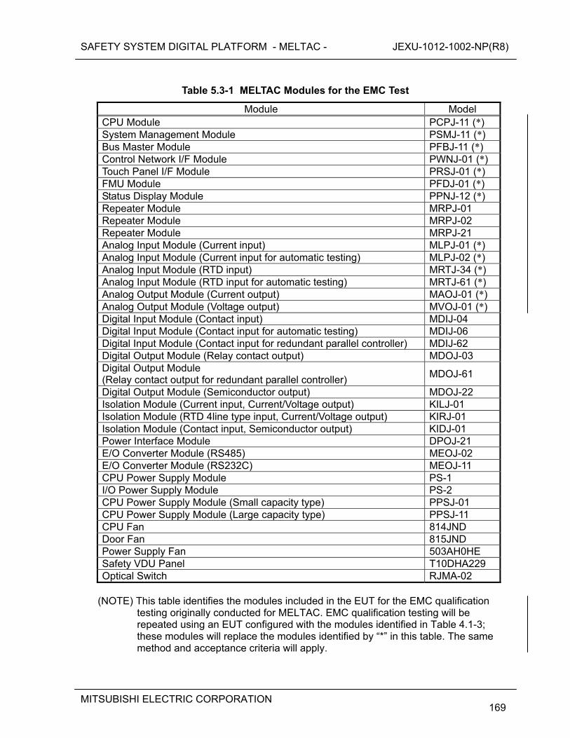
SAFETY SYSTEM DIGITAL PLATFORM - MELTAC - JEXU-1012-1002-NP(R8)
MITSUBISHI ELECTRIC CORPORATION
169
Table 5.3-1 MELTAC Modules for the EMC Test
Module Model CPU Module PCPJ-11 (*) System Management Module PSMJ-11 (*) Bus Master Module PFBJ-11 (*) Control Network I/F Module PWNJ-01 (*) Touch Panel I/F Module PRSJ-01 (*) FMU Module PFDJ-01 (*) Status Display Module PPNJ-12 (*) Repeater Module MRPJ-01 Repeater Module MRPJ-02 Repeater Module MRPJ-21 Analog Input Module (Current input) MLPJ-01 (*) Analog Input Module (Current input for automatic testing) MLPJ-02 (*) Analog Input Module (RTD input) MRTJ-34 (*) Analog Input Module (RTD input for automatic testing) MRTJ-61 (*) Analog Output Module (Current output) MAOJ-01 (*) Analog Output Module (Voltage output) MVOJ-01 (*) Digital Input Module (Contact input) MDIJ-04 Digital Input Module (Contact input for automatic testing) MDIJ-06 Digital Input Module (Contact input for redundant parallel controller) MDIJ-62 Digital Output Module (Relay contact output) MDOJ-03 Digital Output Module (Relay contact output for redundant parallel controller)
MDOJ-61
Digital Output Module (Semiconductor output) MDOJ-22 Isolation Module (Current input, Current/Voltage output) KILJ-01 Isolation Module (RTD 4line type input, Current/Voltage output) KIRJ-01 Isolation Module (Contact input, Semiconductor output) KIDJ-01 Power Interface Module DPOJ-21 E/O Converter Module (RS485) MEOJ-02 E/O Converter Module (RS232C) MEOJ-11 CPU Power Supply Module PS-1 I/O Power Supply Module PS-2 CPU Power Supply Module (Small capacity type) PPSJ-01 CPU Power Supply Module (Large capacity type) PPSJ-11 CPU Fan 814JND Door Fan 815JND Power Supply Fan 503AH0HE Safety VDU Panel T10DHA229 Optical Switch RJMA-02
(NOTE) This table identifies the modules included in the EUT for the EMC qualification
testing originally conducted for MELTAC. EMC qualification testing will be repeated using an EUT configured with the modules identified in Table 4.1-3; these modules will replace the modules identified by “*” in this table. The same method and acceptance criteria will apply.
SAFETY SYSTEM DIGITAL PLATFORM - MELTAC - JEXU-1012-1002-NP(R8)
MITSUBISHI ELECTRIC CORPORATION
170
5.3.2 Description of Tests 5.3.2.1 Conducted Emissions, High Frequency (CE102) Test The test is performed according to the method set forth in MIL-STD-461E, as follows: a) Method
The conducted emission from the input power lead cable of the EUT is measured to confirm that the electromagnetic conducted emission from the EUT does not exceed the specified value.
b) Test Subject The test subject is the AC input power lead cable including return and the ground cable of the EUT.
[
] 5.3.2.2 Radiated Emissions, Magnetic Field (RE101) Test The test is performed according to the method set forth in MIL-STD-461E, as follows: a) Method
A loop sensor is placed on the surface of the object EUT to measure and confirmed that the magnetic field radiated emission from the EUT does not exceed the specified value.
b) Test Subject
The test subjects are the EUT enclosure, the electrical cable interface and the safety VDU panel. The four surfaces are scanned in 360 degrees with the loop sensor at positions at the center of the location (height) where the module is mounted.
[
] 5.3.2.3 Radiated Emission, Electric Field (RE102) Test The test is performed according to the method set forth in MIL-STD-461E, as follows: a) Method
Antennas are placed at the position specified for each frequency range from the border of the setup environment including the interface cable in order to confirm that the electric field radiated emission from the EUT does not exceed the specified value.
SAFETY SYSTEM DIGITAL PLATFORM - MELTAC - JEXU-1012-1002-NP(R8)
MITSUBISHI ELECTRIC CORPORATION
171
b) Test Subject The test subjects are the EUT enclosure, the all interface cables and the safety VDU panel.
[
] 5.3.2.4 Conducted Susceptibility, Low Frequency (CS101) Test for Power Leads According to section 4 of RG1.180, the CS101 test is mentioned as the MIL-STD-461E test method that can be applied as the conducted EMI/RFI susceptibility power leads. This test method is not applied to the signal lead. The test is performed according to the method set forth in MIL-STD-461E, as follows: a) Method
Confirm that the EUT can withstand the signal connected to the AC input power lead. b) Test Subject
The test subject is AC input power lead to the EUT. [
] 5.3.2.5 Conducted Susceptibility, High Frequency (CS114) Test for Power Leads The CS114 test is applicable to all interconnecting leads including the power leads of the EUT. This section describes the CS114 test that is applied to the power and control lines described in section 4.1.2 of RG1.180. The test is performed according to the method set forth in MIL-STD-461E, as follows: a) Method
Confirm that the EUT can withstand the RF signals coupled onto the EUT associated cabling. b) Test Subject
One each of the AC input power cable and the control cables (input and output cables of the Digital I/O modules and Power Interface Module) to the EUT
[
]
SAFETY SYSTEM DIGITAL PLATFORM - MELTAC - JEXU-1012-1002-NP(R8)
MITSUBISHI ELECTRIC CORPORATION
172
5.3.2.6 Conducted Susceptibility, High Frequency (CS114) Test for Signal Leads The CS114 test is applicable to all interconnecting leads including the power leads of the EUT. This section describes the CS114 test that is applied to the signal line described in section 4.2 of RG1.180. The test is performed according to the method set forth in MIL-STD-461E, as follows: a) Method
Confirm that the EUT can withstand the RF signals coupled onto the EUT associated cabling. b) Test Subject
One each of the signal cables (input and output cables of the Analog I/O modules, the Isolation Modules and the RGB cables) to the EUT
[
] 5.3.2.7 Conducted Susceptibility, Bulk Cable Injection, Impulse Excitation (CS115) Test According to section 4.2 of RG1.180, the CS115 test is mentioned as the MIL-STD-461E test method that can be applied as the conducted EMI/RFI susceptibility test along the power leads for the interconnecting signal leads. This test method is not applied to the power lead. The test is performed according to the method set forth in MIL-STD-461E as follows: a) Method
Confirm that the EUT can withstand the impulse signals coupled onto the EUT associated cabling.
b) Test Subject
One each of the signal cables (input and output cables of the Analog I/O modules, the Digital I/O modules, Power interface Module, the Isolation Modules and the RGB cables) to the EUT
[
]
SAFETY SYSTEM DIGITAL PLATFORM - MELTAC - JEXU-1012-1002-NP(R8)
MITSUBISHI ELECTRIC CORPORATION
173
5.3.2.8 Conducted Susceptibility, Damped Sinusoidal Transients (CS116) Test According to section 4.2 of RG1.180, the CS116 test is mentioned as the MIL-STD-461E test method that can be applied as the conducted EMI/RFI susceptibility test along the power cables. This test method is not applied to the power lead. The test is performed according to the method set forth in MIL-STD-461E as follows: a) Method
Confirm that the EUT can withstand the damped sinusoidal transients coupled onto the EUT associated cabling.
b) Test Subject
One each of the signal cables (input and output cables of the Analog I/O modules, the Digital I/O modules, Power Interface Module, the Isolation Modules and the RGB cables) to the EUT
[
] 5.3.2.9 Radiated Susceptibility, Electric Field (RS103) Test The test is performed according to the method set forth in MIL-STD-461E as follows: a) Method
Confirm that the EUT can withstand the electric field emitted from the antenna. b) Test Subject
The test subjects are the EUT enclosure, the all interface cables and the safety VDU panel. Since the EUT enclosure is placed on the floor as in actual plant conditions, and, since its height measures 7.55 ft (2300 mm), the direction of emission of the radiated electric field to the EUT enclosure is in 4 horizontal directions. The top and the bottom parts are not likely to be affected by the electric field.
[
]
SAFETY SYSTEM DIGITAL PLATFORM - MELTAC - JEXU-1012-1002-NP(R8)
MITSUBISHI ELECTRIC CORPORATION
174
5.3.2.10 Surge Withstand, Ring Wave Test The test is performed according to the method set forth in IEC61000-4-12 as follows. For the withstand voltage of the test, the B Medium Exposure is selected out of the location categories described in IEEE Std C62.41-1991, and the corresponding surge voltage level is applied. a) Method
Confirm that the EUT withstands the transient damped phenomenon (Ring Wave) generated by the low-voltage power network applied to the input power lead cable.
b) Test Subject
The test subject is the AC input power lead to the EUT. [
] 5.3.2.11 Surge Withstand, Combination Wave Test The test is performed according to the method set forth in IEC61000-4-5 as follows. For the withstand voltage of the test, the B Medium Exposure was selected out of the location categories described in IEEE Std C62.41-1991, and the according surge level was applied. a) Method
Confirm that the EUT withstands the unidirectional surge generated by the over-voltage due to the transient phenomenon of switching and lightning applied to the input power lead cable.
b) Test Subject
The test subject is the AC input power lead to the EUT. [
] 5.3.2.12 Surge Withstand, Electrically Fast Transients/bursts Test The test is performed according to the method set forth in IEC61000-4-4 as follows. For the withstand voltage of the test, the B Medium Exposure was selected out of the location categories described in IEEE Std C62.41-1991, and the according surge voltage level was applied. a) Method
Confirm that the EUT withstands the electrical fast transient/burst: EFT/B applied to the input power lead cable.
b) Test Subject
The test subject is the AC input power lead to the EUT.
SAFETY SYSTEM DIGITAL PLATFORM - MELTAC - JEXU-1012-1002-NP(R8)
MITSUBISHI ELECTRIC CORPORATION
175
[
]
SAFETY SYSTEM DIGITAL PLATFORM - MELTAC - JEXU-1012-1002-NP(R8)
MITSUBISHI ELECTRIC CORPORATION
176
5.4 Electrostatic Discharge Test
For the MELTAC platform, the ESD test has been successfully performed based on IEC61000-4-2 with test level-2, in accordance with Annex A (maximum charge voltage is 4 kV). This maximum charge voltage is based on the MELTAC Cabinet being installed in Japan on the floor using antistatic materials or concrete. To avoid any special ESD maintenance precautions for US applications, an additional ESD test was also performed to level-4. This section describes the test, acceptance criteria and results. The test is performed with the MELTAC Cabinet fully equipped with a typical configuration of MELTAC components required for a safety protection system. The following acceptance criteria are applied for equipment that can be accessed during operation: There is no equipment damage Processors continue to function Data communications is not disrupted Discrete I/O does not change state Analog I/O levels do not vary by more than 3% There is no VDU image disturbance This is the same acceptance criteria as for the EMI/RFI susceptibility test. For equipment that can be accessed only during maintenance, the acceptance criteria is only to ensure no equipment damage. The ESD test is performed according to the method set forth in IEC61000-4-2, as follows: a) Method
Confirm that the EUT can withstand ESD, which may occur from personnel coming into contact at human-machine interface points of equipment during normal operation and when the equipment is out of service during maintenance.
b) Test Subject The following equipment points are likely to be accessed by personnel during normal equipment operation.
The touch panel of the safety VDU panel and the surrounding area. The front/rear door handles of the cabinet and the surrounding area The switches of the Status Display Module and the surrounding area. The switches and fuses of the Fans, and the surrounding area. The front panel of the Power Supply Modules and Analog Output Modules.
Other human-machine interface points of the equipment are expected to be accessed only during maintenance.
[
SAFETY SYSTEM DIGITAL PLATFORM - MELTAC - JEXU-1012-1002-NP(R8)
MITSUBISHI ELECTRIC CORPORATION
177
]
SAFETY SYSTEM DIGITAL PLATFORM - MELTAC - JEXU-1012-1002-NP(R8)
MITSUBISHI ELECTRIC CORPORATION
178
5.5 Isolation Test [
]
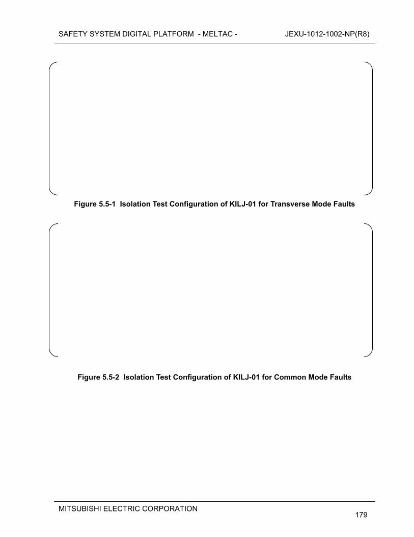
SAFETY SYSTEM DIGITAL PLATFORM - MELTAC - JEXU-1012-1002-NP(R8)
MITSUBISHI ELECTRIC CORPORATION
179
Figure 5.5-1 Isolation Test Configuration of KILJ-01 for Transverse Mode Faults
Figure 5.5-2 Isolation Test Configuration of KILJ-01 for Common Mode Faults
SAFETY SYSTEM DIGITAL PLATFORM - MELTAC - JEXU-1012-1002-NP(R8)
MITSUBISHI ELECTRIC CORPORATION
180
Figure 5.5-3 Isolation Test Configuration of KIDJ-01 for Transverse Mode Faults
Figure 5.5-4 Isolation Test Configuration of KIDJ-01 for Common Mode Faults

SAFETY SYSTEM DIGITAL PLATFORM - MELTAC - JEXU-1012-1002-NP(R8)
MITSUBISHI ELECTRIC CORPORATION
181
[
]
SAFETY SYSTEM DIGITAL PLATFORM - MELTAC - JEXU-1012-1002-NP(R8)
MITSUBISHI ELECTRIC CORPORATION
182
6.0 LIFE CYCLE In 2006, MELCO started the activities to apply MELTAC as a digital platform for Safety Systems in US nuclear facilities. At that time MELCO assessed the original QAP and the original MELTAC development process for conformance to US requirements. A deficiency regarding the IV&V required in IEEE 7-4.3.2 was identified. To compensate for this deficiency MELCO added assessment and IV&V procedures and developed [ ] which invoked those procedures. In accordance with [ ], MELCO conducted assessments of the existing Software and related documents during the period 2006-2007. These assessments resulted in additional IV&V for some software, in accordance with [ ]. This reassessment and added IV&V program is referred to as the original US Conformance Program (UCP). [
] The development of the [ ] is described in Section 6.3.1.
SAFETY SYSTEM DIGITAL PLATFORM - MELTAC - JEXU-1012-1002-NP(R8)
MITSUBISHI ELECTRIC CORPORATION
183
The “MELTAC Platform Basic Software Program Manual (SPM)” [ ] provides the generic plans that are followed under the [ ] for all activities related to all future activities for the MELTAC basic software life cycle. This document is applicable to any design modifications to the current MELTAC basic software to accommodate any product deficiencies and any product enhancements, and to any new MELTAC product development. The life cycle processes described in Section 6.1.3 through 6.1.12 and Section 6.2 establish the minimum requirements for the lifecycle specified in the [ ]. To preclude the need for any additional post development assessments, the [ ] includes the requirements used for the UCP described in Section 6.1.7.
[
] Section 6.4 describes the assessment for the conformance of MELTAC to BTP 7-14.
Section 6.1 describes the lifecycle of MELTAC based on [ ]. Section 6.1.1 and 6.1.2 describes the overview of MELCO’s QA program for the current
MELTAC basic software, [ ]. Section 6.1.3 through 6.1.6 describes the original design process lifecycle of MELTAC. Section 6.1.7 describes the original UCP conducted from 2006 to 2007, [ ], and the
expanded UCP conducted from 2009 to 2010, [ ]. Section 6.1.8 through 6.1.11 describes the lifecycle of MELTAC after its development phase,
based on [ ]. Section 6.1.12 describes the MELTAC software safety analysis for the current MELTAC basic
software, [ ]. Section 6.2 describes the quality record management, failure management, and identification of
MELTAC. This section is applicable to [ ].
Sections 6.1.3 through 6.1.12 and 6.2 are applicable to the current MELTAC platform. The processes defined in these sections established the basis for the assessment of the original MELTAC development conducted in the MRP, which is described in Section 6.3. The life cycle requirements described in Sections 6.1.3 through 6.1.12 and 6.2, establish the minimum requirements for the “MELTAC Platform Basic Software Program Manual (SPM)” [ ], which is used to manage the MELTAC software life cycle under the [ ].
SAFETY SYSTEM DIGITAL PLATFORM - MELTAC - JEXU-1012-1002-NP(R8)
MITSUBISHI ELECTRIC CORPORATION
184
6.1 Life Cycle Process This section describes key elements of the lifecycle process for the Basic components (software and hardware) of the MELTAC Platform, based on [ ]. This section also includes the assessment of the original MELTAC development (prior to [ ]), which was also conducted under [ ]. The life cycle processes for [ ] establish the minimum requirements for the processes defined in the “MELTAC Platform Basic Software Program Manual (SPM)” [
], which is used to manage the MELTAC software life cycle under the [ ].
6.1.1 Overview of the MELTAC Quality Assurance Program As described in Section 7.1, the MELTAC platform has accumulated many years of positive performance records in various non-safety system applications such as the Plant Control and Monitoring System in nuclear plants operating in Japan. Based on its excellent performance in numerous non-safety applications, the MELTAC platform has been applied to all plant systems non-safety and safety in one of the Japanese nuclear plants under construction. These systems were shipped to the site. The original quality assurance program (referred to as Original QAP) used for the MELTAC platform development was based on the Japanese Standard JEAG4101 and ISO9001. Since MELCO planned to apply the platform to safety systems in US nuclear facilities, the following quality assurance procedures were adopted in [ ], “NPD Procedure [ ]: Safety System Digital Platform Quality Assurance Program”, hence forth referred to as [
]. “NPD Procedure [ ]: Safety System Digital Platform Cyber Security Program”, hence forth referred to as [ ], and “NPD Procedure [ ]: Safety System Digital Platform Software V&V Procedures”, hence forth referred to as [ ]. Unless specifically noted, procedures applicable to software encompass all MELTAC basic software and firmware, regardless of which module or media that software may reside. These procedures address all requirements of IEEE7-4.3.2-2003, including the applicable Regulatory Guides and IEEE software standards. In addition, 10CFR Part 50 Appendix B was used as a guideline. The requirements of these quality assurance procedures are described in the Sections below. [
]
SAFETY SYSTEM DIGITAL PLATFORM - MELTAC - JEXU-1012-1002-NP(R8)
MITSUBISHI ELECTRIC CORPORATION
185
Table 6.1-1 QA Procedures
[
] Platform designs (hardware or software) developed prior to the [ ] (referred to as Existing Platform) will be reused for US nuclear applications. The Original QAP and records of the Existing Platform have been assessed against the [ ] procedures, to ensure suitable quality of the Existing Platform. This assessment, which was conducted under [ ], is referred to as the US Conformance Program (UCP). The result of the UCP showed the development process for the Existing Platform conformed to [
] except the independent V&V requirement and other minor deficiencies. The MRP described in Section 6.3.1, provided an additional assessment conducted under the App. B-based QAP, using the guidance of EPRI-TR106439 and EPRI TR-107330. Therefore MELCO developed the “MELTAC US Conformance Program” (UCP), which is the combination of the corrective actions taken to compensate for differences between the Original QAP and [ ], and the assessment of the developed software by the independent V&V Team. The detail is described in Section 6.1.7.
The requirements of [ ] are described in the following sections: ・ Quality Assurance (6.1.2) ・ Management (6.1.3) The requirements of [ ] are described in the following section: ・ Development (6.1.4) ・ Configuration Management (6.1.5) ・ Installation (6.1.8) ・ Maintenance (6.1.9) ・ Training (6.1.10) ・ Operation (6.1.11) ・ Software Safety Plan (6.1.12)
SAFETY SYSTEM DIGITAL PLATFORM - MELTAC - JEXU-1012-1002-NP(R8)
MITSUBISHI ELECTRIC CORPORATION
186
The requirements of [ ] are described in the following section: ・ Secure Development Environment Management (6.1.6) The end of each section summaries the assessment of the Original QAP against the requirements of that section. Hardware procured or manufactured prior to the App. B-based QAP will not be used for US nuclear applications. All hardware procurement, manufacturing and related testing for US applications will be conducted under the App. B-based QAP. Therefore, these areas of the product life cycle are not included in the MRP described in Section 6.3.1.
SAFETY SYSTEM DIGITAL PLATFORM - MELTAC - JEXU-1012-1002-NP(R8)
MITSUBISHI ELECTRIC CORPORATION
187
6.1.2 Quality Assurance Program Rev 2 The requirements for MELTAC platform quality assurance are set forth in various in-house procedures, in accordance with IEEE7-4.3.2-2003 and IEEE1012-2004. In addition, 10CFR Part 50 Appendix B was used as a guideline. These in-house QA procedures are shown in Figure 6.1-1 . [
]
Figure 6.1-1 Outline of In-house QA Procedures System and Relationship of Various Plans

SAFETY SYSTEM DIGITAL PLATFORM - MELTAC - JEXU-1012-1002-NP(R8)
MITSUBISHI ELECTRIC CORPORATION
188
[
]
[
]
SAFETY SYSTEM DIGITAL PLATFORM - MELTAC - JEXU-1012-1002-NP(R8)
MITSUBISHI ELECTRIC CORPORATION
189
6.1.3 Management This section describes requirements for management of MELTAC platform development. These requirements are based on IEEE 7-4.3.2-2003 and IEEE1012-2004. [
] 6.1.3.1 Organization [
] 6.1.3.2 Project Plan [
SAFETY SYSTEM DIGITAL PLATFORM - MELTAC - JEXU-1012-1002-NP(R8)
MITSUBISHI ELECTRIC CORPORATION
190
] 6.1.3.3 Personnel Ability [
] Existing Platform Assessment based on UCP There is no difference between the personnel ability requirements for the Original QA Program and [ ]. 6.1.4 Development The outline of the Software Development Plan is shown in Figure 6.1-2, A similar process is applied to hardware components. The hardware development process is described in Table 6.1-3. [
]
SAFETY SYSTEM DIGITAL PLATFORM - MELTAC - JEXU-1012-1002-NP(R8)
MITSUBISHI ELECTRIC CORPORATION
191
Figure 6.1-2 Outline of Software Development Plan
[
]
SAFETY SYSTEM DIGITAL PLATFORM - MELTAC - JEXU-1012-1002-NP(R8)
MITSUBISHI ELECTRIC CORPORATION
192
Table 6.1-2 Contents of Activity in Each Phase
SAFETY SYSTEM DIGITAL PLATFORM - MELTAC - JEXU-1012-1002-NP(R8)
MITSUBISHI ELECTRIC CORPORATION
193
[
]
Figure 6.1-3 Outline of Problem Tracking/Resolution Process
SAFETY SYSTEM DIGITAL PLATFORM - MELTAC - JEXU-1012-1002-NP(R8)
MITSUBISHI ELECTRIC CORPORATION
194
The hardware development process consists of the Design Team activity and the independent review and test activity by people other than the actual design staff. The activities in each phase are shown in the table below.
Table 6.1-3 Contents of Hardware Development Activity in Each Phase
[
] Existing Platform Assessment based on UCP [
SAFETY SYSTEM DIGITAL PLATFORM - MELTAC - JEXU-1012-1002-NP(R8)
MITSUBISHI ELECTRIC CORPORATION
195
] The detailed assessment of the Development process used for the Existing Platform is provided in Section 6.1.7. 6.1.5 Configuration Management The configuration management process is in accordance with NPD Standard [ ], which conforms to RG1.169 and IEEE828-1990. The key elements of the configuration management program are described below. [
]
The assessment of the configuration management activities for the Existing Platform is provided in Section 6.1.5.8. 6.1.5.1 Organization/Responsibility [
] 6.1.5.2 Base-Line [
SAFETY SYSTEM DIGITAL PLATFORM - MELTAC - JEXU-1012-1002-NP(R8)
MITSUBISHI ELECTRIC CORPORATION
196
] 6.1.5.3 Other Configuration Management Items In addition to products of the Design and V&V Teams, the following items are maintained under the Configuration Management program. [
] 6.1.5.4 Reporting A project Configuration Management Report is periodically generated to document the applicable version of all project products that are maintained under configuration management, including all that have been base-lined. The frequency of updating this report is defined in the Project Plan. 6.1.5.5 Change Management [
]
SAFETY SYSTEM DIGITAL PLATFORM - MELTAC - JEXU-1012-1002-NP(R8)
MITSUBISHI ELECTRIC CORPORATION
197
6.1.5.6 Storage and Retrieval [
] 6.1.5.7 Reviews [
] 6.1.5.8 Existing Platform Assessment based on UCP The configuration management of the Existing Platform was assessed against the current Configuration Management program. The following minor deficiencies were identified: [
]
SAFETY SYSTEM DIGITAL PLATFORM - MELTAC - JEXU-1012-1002-NP(R8)
MITSUBISHI ELECTRIC CORPORATION
198
6.1.6 Secure Development Environment Management The Secure Development Environment Management Program is in accordance with NPD Standard [ ], which conforms to RG1.152. The overall Secure Development Environment Management Program ensures the followings: a) There is no unintended code included in the software during the process of software
development. b) Unintended changes to the software installed in the system are prevented and detected. For item a), the Section 6.1.6.1 and 6.1.6.2 describe the security measures in the development process of the MELTAC platform software and the MELTAC engineering tool. These requirements and procedures are documented. The security measures in the development process of the application software are described in application level documentation. For example, for the US-APWR these activities are described in the US-APWR Software Program Manual (MUAP-07017) The US-APWR Software Program Manual also describes change management and security measures for the application software during the final integration and testing of plant systems prior to shipment. For item b), application level documentation describes security measures in the system design which prevent unintended changes while the system is in the plant. For example, for the US-APWR these measures are described in the Safety I&C System Description and Design Process Technical Report for the US-APWR DCD (MUAP-07004). This applies to pre-operational testing and operation. Section 6.1.6.3 describes features of the MELTAC platform, which prevent unintended changes during system operation and allow changes to be detected, should they occur. [
] The Section 6.1.6.4 describes the Existing Platform assessment. 6.1.6.1 Software and FPGA Development/Storage Security Measures [
]
SAFETY SYSTEM DIGITAL PLATFORM - MELTAC - JEXU-1012-1002-NP(R8)
MITSUBISHI ELECTRIC CORPORATION
199
Figure 6.1-4 Security Measures of the Software Development/Storage Environment
[
]
SAFETY SYSTEM DIGITAL PLATFORM - MELTAC - JEXU-1012-1002-NP(R8)
MITSUBISHI ELECTRIC CORPORATION
200
Table 6.1-4 Security Measures of the Software Development/Storage Environment
[
]
SAFETY SYSTEM DIGITAL PLATFORM - MELTAC - JEXU-1012-1002-NP(R8)
MITSUBISHI ELECTRIC CORPORATION
201
6.1.6.2 Security Measures In Each Phase of Development Process This security measures shown in Table 6.1-5 ensure that no unintended code can be introduced during the development process.
Table 6.1-5 Security Measures in the Software Development Process
SAFETY SYSTEM DIGITAL PLATFORM - MELTAC - JEXU-1012-1002-NP(R8)
MITSUBISHI ELECTRIC CORPORATION
202
SAFETY SYSTEM DIGITAL PLATFORM - MELTAC - JEXU-1012-1002-NP(R8)
MITSUBISHI ELECTRIC CORPORATION
203
6.1.6.3 Secure Development Environment Measures During System Operation [
] 6.1.6.4 Existing Platform Secure Development Environment Assessments based on UCP [
] 6.1.7 US Conformance Program for Previously Developed Components [
SAFETY SYSTEM DIGITAL PLATFORM - MELTAC - JEXU-1012-1002-NP(R8)
MITSUBISHI ELECTRIC CORPORATION
204
] 6.1.7.1 Platform Design [
] 6.1.7.2 Software Design 6.1.7.2.1 Software [
SAFETY SYSTEM DIGITAL PLATFORM - MELTAC - JEXU-1012-1002-NP(R8)
MITSUBISHI ELECTRIC CORPORATION
205
] 6.1.7.2.2 FPGA [
] 6.1.7.3 Program Design, Coding, Unit Test 6.1.7.3.1 Software [
SAFETY SYSTEM DIGITAL PLATFORM - MELTAC - JEXU-1012-1002-NP(R8)
MITSUBISHI ELECTRIC CORPORATION
206
] 6.1.7.3.2 FPGA [
]
SAFETY SYSTEM DIGITAL PLATFORM - MELTAC - JEXU-1012-1002-NP(R8)
MITSUBISHI ELECTRIC CORPORATION
207
6.1.7.4 Integration Test This section is composed of two parts. The first part describes the Integration Tests performed during the original UCP and the assessment of past Integration Tests. The combination of the both results fulfills the Platform Specification, which conforms to the regulatory requirements. The second part describes the Integration Tests for the expanded UCP. 6.1.7.4.1 Integration Test - original UCP [
SAFETY SYSTEM DIGITAL PLATFORM - MELTAC - JEXU-1012-1002-NP(R8)
MITSUBISHI ELECTRIC CORPORATION
208
] Final assessment result - The V&V Team confirmed that all items for the existing MELTAC platform integration test satisfied the requirements of [ ]. [
] Based on the overall UCP the V&V Team reached the conclusion that all the requirements for the safety system are met. 6.1.7.4.2 Integration Test - expanded UCP [
] 6.1.8 Software Installation [
SAFETY SYSTEM DIGITAL PLATFORM - MELTAC - JEXU-1012-1002-NP(R8)
MITSUBISHI ELECTRIC CORPORATION
209
] Existing Platform Assessment based on UCP There are no differences between the Existing Platform and the MELTAC platform for service in U.S. in terms of software installation procedures or requirements.
SAFETY SYSTEM DIGITAL PLATFORM - MELTAC - JEXU-1012-1002-NP(R8)
MITSUBISHI ELECTRIC CORPORATION
210
Figure 6.1-5 Software Installation
SAFETY SYSTEM DIGITAL PLATFORM - MELTAC - JEXU-1012-1002-NP(R8)
MITSUBISHI ELECTRIC CORPORATION
211
6.1.9 Maintenance [
]
Table 6.1-6 Information Provided in the MELTAC Maintenance Manual
Plant owners may supplement the instructions in the Maintenance Manual with plant specific procedures to address administrative issues such as work orders and approvals.
SAFETY SYSTEM DIGITAL PLATFORM - MELTAC - JEXU-1012-1002-NP(R8)
MITSUBISHI ELECTRIC CORPORATION
212
Existing Platform Assessment based on UCP There are no differences between the Existing Platform and the MELTAC platform for service in U.S. in terms of maintenance procedures or requirements. 6.1.10 Training MELCO supports training that assists customers in understanding the working and proper use of the MELTAC platform. [
]
This training is comprised of lecture classes and hands-on training using actual MELTAC Controllers. Below are the major trainings courses: [
] Additional application specific training is described in application level documentation. For example, for the US-APWR training is described in the US-APWR Software Program Manual (MUAP-07017). Existing Platform Assessment based on UCP There are no differences between the Existing Platform and the MELTAC platform for service in U.S. in terms of training procedures or requirements.
SAFETY SYSTEM DIGITAL PLATFORM - MELTAC - JEXU-1012-1002-NP(R8)
MITSUBISHI ELECTRIC CORPORATION
213
6.1.11 Operations [
] 6.1.11.1 Hardware The following hardware measurements and adjustments (as needed) are recommended on a periodic basis, but not more frequently than once every 24 months.
Table 6.1-7 Hardware Measurement
Existing Platform Assessment based on UCP There are no differences between the Existing Platform and the MELTAC platform for service in U.S. in terms of hardware operations procedures or requirements.
SAFETY SYSTEM DIGITAL PLATFORM - MELTAC - JEXU-1012-1002-NP(R8)
MITSUBISHI ELECTRIC CORPORATION
214
6.1.11.2 Software This section describes the upgrade process for the MELTAC basic software. Upgrades or changes to application software are described in application level documentation. For example, for the US-APWR software upgrades are described in the US-APWR Software Program Manual (MUAP-07017).
SAFETY SYSTEM DIGITAL PLATFORM - MELTAC - JEXU-1012-1002-NP(R8)
MITSUBISHI ELECTRIC CORPORATION
215
Table 6.1-8 Software Upgrades Relation
SAFETY SYSTEM DIGITAL PLATFORM - MELTAC - JEXU-1012-1002-NP(R8)
MITSUBISHI ELECTRIC CORPORATION
216
Existing Platform Assessment based on UCP There are no differences between the Existing Platform and the MELTAC platform for service in U.S. in terms of software operations procedures or requirements. 6.1.12 Software Critical Function Analysis [
] As is described in the Section 4.1.3.1 “Basic Software”, MELTAC CPU basic software consists of 9 tasks executed sequentially. [
]
SAFETY SYSTEM DIGITAL PLATFORM - MELTAC - JEXU-1012-1002-NP(R8)
MITSUBISHI ELECTRIC CORPORATION
217
Table 6.1-9 Possible Hazards
[
]
SAFETY SYSTEM DIGITAL PLATFORM - MELTAC - JEXU-1012-1002-NP(R8)
MITSUBISHI ELECTRIC CORPORATION
218
6.2 Life Cycle Management [
] 6.2.1 Quality Records Management Quality records are collected and controlled. This Quality Assurance Program ensures records of completed items and activities affecting quality are appropriately stored. The records and their retention times are defined. 6.2.2 Failure and Error Reporting and Corrective Action MELCO has supported the utilities’ maintenance of the shipped equipments. MELCO participates in the annual inspection and has provided 24 hours on call support service and dedicated Maintenance Team per plant in Japan. Therefore all customer’s claims and Irregular Events for the shipped equipments are reported directly to MELCO, whether the plant is in operation or in the maintenance. 6.2.2.1 Policy of MELTAC Troubleshooting When any error or failure occur, Per Plant Maintenance Team executes the primary investigation and the emergency treatment against the customer’s claim and sends detailed Information to the factory for the further investigation. At the factory side, the procedure of troubleshooting is prepared to solve problem and for the preventive actions for other plants.(See 6.2.2.2) MELCO has recorded all phenomena, causes, solutions, and all information about troubles at all plants. So MELCO collects all field equipment Failure and Error Information in-depth. Based on this information, MELCO has analyzed the platform reliability to improve quality of the MELTAC platform. 6.2.2.2 Troubleshooting Summary The rule, method and form of troubleshooting report to customer will be discussed between MELCO and each customer, in consideration of US regulations (10CFR21) and customer’s situation. This subsection describes the general problem handling process of MELCO. Changes to this process are likely to occur through the normal course of MELCO’s process improvements.
[
SAFETY SYSTEM DIGITAL PLATFORM - MELTAC - JEXU-1012-1002-NP(R8)
MITSUBISHI ELECTRIC CORPORATION
219
]
SAFETY SYSTEM DIGITAL PLATFORM - MELTAC - JEXU-1012-1002-NP(R8)
MITSUBISHI ELECTRIC CORPORATION
220
[
] 6.2.3 Obsolescence Management This section describes obsolescence management program for the MELTAC platform. MELCO uses only parts with an excellent record of production continuity. Regardless, the product service life for nuclear applications covers 20 – 30 years, therefore it is inevitable that many parts will become unavailable. The following sections describe the process used to determine the availability of parts and the process used to evaluate and utilize different parts for substitution. The parts substitution method described in this section is primarily applicable to obsolescence management. However, MELCO may also use the same method of part substitution to ensure adequate parts supply from multiple sources to accommodate supply management issues or production peaks. 6.2.3.1 Obtaining Information on Part Availability [
] 6.2.3.2 Selecting Replacement Parts [
]
SAFETY SYSTEM DIGITAL PLATFORM - MELTAC - JEXU-1012-1002-NP(R8)
MITSUBISHI ELECTRIC CORPORATION
221
6.2.3.3 Verification after Replacement [
] 6.2.4 Identification [
SAFETY SYSTEM DIGITAL PLATFORM - MELTAC - JEXU-1012-1002-NP(R8)
MITSUBISHI ELECTRIC CORPORATION
222
] 6.2.5 Reliability Database [
SAFETY SYSTEM DIGITAL PLATFORM - MELTAC - JEXU-1012-1002-NP(R8)
MITSUBISHI ELECTRIC CORPORATION
223
] 6.3 Establishment of 10 CFR Part 50 Appendix B-based QA Program, and MELTAC Re-
evaluation Program 6.3.1 Establishment of 10 CFR Part 50 Appendix B-based QA Program [
]
SAFETY SYSTEM DIGITAL PLATFORM - MELTAC - JEXU-1012-1002-NP(R8)
MITSUBISHI ELECTRIC CORPORATION
224
Table 6.3-1 Relationship Between App.B-based QAP and Previous QAP
SAFETY SYSTEM DIGITAL PLATFORM - MELTAC - JEXU-1012-1002-NP(R8)
MITSUBISHI ELECTRIC CORPORATION
225
6.3.2 MELTAC Re-evaluation Program [
] 6.4 Basic Software Program Manual [
SAFETY SYSTEM DIGITAL PLATFORM - MELTAC - JEXU-1012-1002-NP(R8)
MITSUBISHI ELECTRIC CORPORATION
226
]
6.5 MELTAC Engineering Tool Life Cycle The MELTAC engineering tool was developed and managed under MELCO QAP for non-safety items (Complies with ISO 9001). It has demonstrated correct performance for nuclear applications of the MELTAC platform since 1987. Since the MELTAC engineering tool is not credited for any safety-related functions (ie. the output of the MELTAC engineering tool is manually verified), the UCP and MRP have not been applied to the MELTAC engineering tool. The MELTAC engineering tool will continue to be managed under the MELCO QAP for non-safety items, and the output of the tool will continue to be manually verified. Since the tool is used to develop application software, the application development and verification process is defined in application level documentation and managed under the applicable application level QAP. For example, for the US-APWR, the application software development process, is defined in the US-APWR Software Program Manual (MUAP-07017).
SAFETY SYSTEM DIGITAL PLATFORM - MELTAC - JEXU-1012-1002-NP(R8)
MITSUBISHI ELECTRIC CORPORATION
227
7.0 EQUIPMENT RELIABILITY 7.1 History of Operation Development of the MELTAC platform was started in 1985 aiming at applications in nuclear non-safety systems in the short term and applications in nuclear safety protection systems in the longer term. The first non-safety system application was in 1987. This system accumulated several years of field experience in nuclear plants. This field experience allowed improvement of the product for application to safety systems. The first safety prototype system went through third party Qualification Test by a Japanese domestic agency during the period from 1987 to 1990. The platform’s basic hardware and software design were entirely accepted. The latest digital technology development was started in 1988 for the purpose of improvements reflecting additional field operating experience and new features to allow application of the MELTAC platform to a complete plant-wide digital I&C system. The latest platform was first applied to nuclear plant non-safety systems in 2001. Shown in Figure 7.1-1 is the history of the MELTAC development, the records of operation, and the application plans. The MELTAC operation status at the time of this document revision is described below. a) Operating at five PWR plants in Japan, each for an average of ten years. b) Used for 50 non-safety system applications per plant. c) Combined total operation time of over 20,000,000 hours d) No plant system has ever suffered shutdown due to software- or hardware-related problems.
The MELTAC platform has now been applied for total plant-wide digital upgrades at two Japanese nuclear plants. The platform is used throughout these plants, including the digital protection system and digital VDU-based main control room. The plants restarted with the complete plant-wide MELTAC system July 2009. The MELTAC platform has also been applied for a Japanese nuclear plant under construction. The platform is used throughout the plant, including the digital protection system and digital VDU-based main control room. The complete digital system was shipped to the plant site recently after completing a 22 month factory acceptance test. Commercial operation of this plant is expected to begin in late 2009. MELTAC systems are currently in production for six new nuclear plants in China. The platform is used for the digital plant protection systems. All MELTAC operating experience to date has been encompassed in the MELTAC product described in this Technical Report. Additional experience gained through future applications is continuously encompassed in ongoing product improvements. All changes to the product are conducted under the App.B-based QAP described in Section 6. Changes to the product that also change the descriptions in this Technical Report will be identified in future licensing submittals.
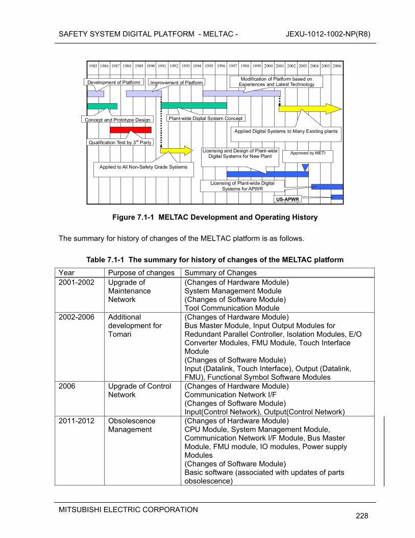
SAFETY SYSTEM DIGITAL PLATFORM - MELTAC - JEXU-1012-1002-NP(R8)
MITSUBISHI ELECTRIC CORPORATION
228
1995
20062005 2004 2003 2002 2001200019991998199719961994199319921991 1990 1989 1988 1987 1986 1985
Development of Platform
Concept and Prototype Design
Qualification Test by 3rd Party
Plant-wide Digital System Concept
Licensing and Design of Plant-wide Digital Systems for New Plant
Modification of Platform based on Experiences and Latest Technology
Applied to All Non-Safety Grade Systems
Applied Digital Systems to Many Existing plants
Improvement of Platform
Approved by METI
Licensing of Plant-wide Digital Systems for APWR
US-APWR
Figure 7.1-1 MELTAC Development and Operating History
The summary for history of changes of the MELTAC platform is as follows.
Table 7.1-1 The summary for history of changes of the MELTAC platform
Year Purpose of changes Summary of Changes 2001-2002 Upgrade of
Maintenance Network
(Changes of Hardware Module) System Management Module (Changes of Software Module) Tool Communication Module
2002-2006 Additional development for Tomari
(Changes of Hardware Module) Bus Master Module, Input Output Modules for Redundant Parallel Controller, Isolation Modules, E/O Converter Modules, FMU Module, Touch Interface Module (Changes of Software Module) Input (Datalink, Touch Interface), Output (Datalink, FMU), Functional Symbol Software Modules
2006 Upgrade of Control Network
(Changes of Hardware Module) Communication Network I/F (Changes of Software Module) Input(Control Network), Output(Control Network)
2011-2012 Obsolescence Management
(Changes of Hardware Module) CPU Module, System Management Module, Communication Network I/F Module, Bus Master Module, FMU module, IO modules, Power supply Modules (Changes of Software Module) Basic software (associated with updates of parts obsolescence)
SAFETY SYSTEM DIGITAL PLATFORM - MELTAC - JEXU-1012-1002-NP(R8)
MITSUBISHI ELECTRIC CORPORATION
229
7.2 Mean Time between Failures (MTBF) Analysis
MTBF is calculated for each MELTAC module. These values are then used to assess the reliability of complete MELTAC controllers for each system, as explained in Section 7.3. The calculation of MTBF values is based on MIL-HDBK-217F NOTICE2. MTBF values are calculated by adding up the failure rates of the components which make up each module and finding the reciprocal of the module's failure rate thus obtained. For the MIL-HDBK, failure rate is defined by the type of the component, taking operating conditions and reliability factor into consideration, so it represents a generic reliability assessment technique. Environmental conditions used for the calculation are described below. [
] MTBF of each module is shown Table 7.2-1. The actual MTBF value determined from recent operating history is more than the calculated MTBF value. Therefore, the calculation method and the resulting calculated values are appropriate for assessing system reliability. Table 7.2-1 provides the calculated FIT and MTBF for each MELTAC module. If a module is updated, FIT and MTBF will be calculated using the same method, and an equivalent reliability will be demonstrated. The same method of calculating FIT and MTBF will also be used for any new modules. The impact on overall controller reliability for any new modules is evaluated in accordance with Section 7.3.
SAFETY SYSTEM DIGITAL PLATFORM - MELTAC - JEXU-1012-1002-NP(R8)
MITSUBISHI ELECTRIC CORPORATION
230
Table 7.2-1 Failure rate of modules
SAFETY SYSTEM DIGITAL PLATFORM - MELTAC - JEXU-1012-1002-NP(R8)
MITSUBISHI ELECTRIC CORPORATION
231
SAFETY SYSTEM DIGITAL PLATFORM - MELTAC - JEXU-1012-1002-NP(R8)
MITSUBISHI ELECTRIC CORPORATION
232
7.3 Controller Reliability Analysis The failure rate of any MELTAC system, as a whole, depends on the complete system configuration. Variations for each application include:
the number and configuration of redundant divisions the number and configuration of controllers within each division the redundancy configuration within each controller the configuration of I/O and Communications Interface modules and the criticality of
those interfaces to the safety function (ie. the safety function logic design) The overall reliability for safety system applications is described in the Safety I&C System Description and Design Process Technical Report for the US-APWR DCD. The MTBF numbers and reliability models used in that Topical Report are based on the methods described in this report. This section describes the method used to determine the reliability of the generic Redundant Parallel Controller. The method for the Single Controller architecture can be extracted from this method. Controller Reliability Analysis is performed as follows.
A reliability model for the system’s safety function is built Using the reliability model, Fault Tree Analysis (FTA) is used to determine the
frequency of: - Spurious actuation of the safety function - Failure to actuate the safety function
The reliability model for a simple system is shown in section 7.3.1. To exemplify the reliability analysis process, Figure 7.3-2 shows the fault tree for spurious actuation of the safety function. The FTA for spurious actuation is explained below.
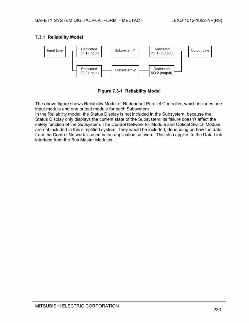
SAFETY SYSTEM DIGITAL PLATFORM - MELTAC - JEXU-1012-1002-NP(R8)
MITSUBISHI ELECTRIC CORPORATION
233
7.3.1 Reliability Model
Dedicated I/O 1 (Input)
Dedicated I/O 2 (Input)
Subsystem-1
Subsystem-2
DedicatedI/O 1 (Output)
DedicatedI/O 2 (output)
Input Line Output Line
Figure 7.3-1 Reliability Model
The above figure shows Reliability Model of Redundant Parallel Controller, which includes one input module and one output module for each Subsystem. In the Reliability model, the Status Display is not included in the Subsystem, because the Status Display only displays the current state of the Subsystem; its failure doesn’t affect the safety function of the Subsystem. The Control Network I/F Module and Optical Switch Module are not included in this simplified system. They would be included, depending on how the data from the Control Network is used in the application software. This also applies to the Data Link interface from the Bus Master Modules.
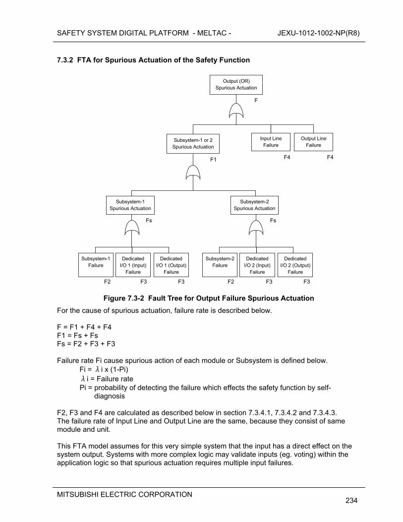
SAFETY SYSTEM DIGITAL PLATFORM - MELTAC - JEXU-1012-1002-NP(R8)
MITSUBISHI ELECTRIC CORPORATION
234
7.3.2 FTA for Spurious Actuation of the Safety Function
F1 F4F4
F
Fs
Subsystem-1 or 2Spurious Actuation
Output (OR) Spurious Actuation
Output LineFailure
Input Line Failure
Subsystem-1 Failure
Dedicated I/O 1 (Input)
Failure
DedicatedI/O 1 (Output)
Failure
Fs
Subsystem-1 Spurious Actuation
Subsystem-2 Spurious Actuation
Subsystem-2Failure
DedicatedI/O 2 (Input)
Failure
Dedicated I/O 2 (Output)
Failure
F2 F3 F3 F2 F3 F3
Figure 7.3-2 Fault Tree for Output Failure Spurious Actuation
For the cause of spurious actuation, failure rate is described below. F = F1 + F4 + F4 F1 = Fs + Fs Fs = F2 + F3 + F3 Failure rate Fi cause spurious action of each module or Subsystem is defined below.
Fi = λi x (1-Pi) λi = Failure rate Pi = probability of detecting the failure which effects the safety function by self-
diagnosis F2, F3 and F4 are calculated as described below in section 7.3.4.1, 7.3.4.2 and 7.3.4.3. The failure rate of Input Line and Output Line are the same, because they consist of same module and unit. This FTA model assumes for this very simple system that the input has a direct effect on the system output. Systems with more complex logic may validate inputs (eg. voting) within the application logic so that spurious actuation requires multiple input failures.
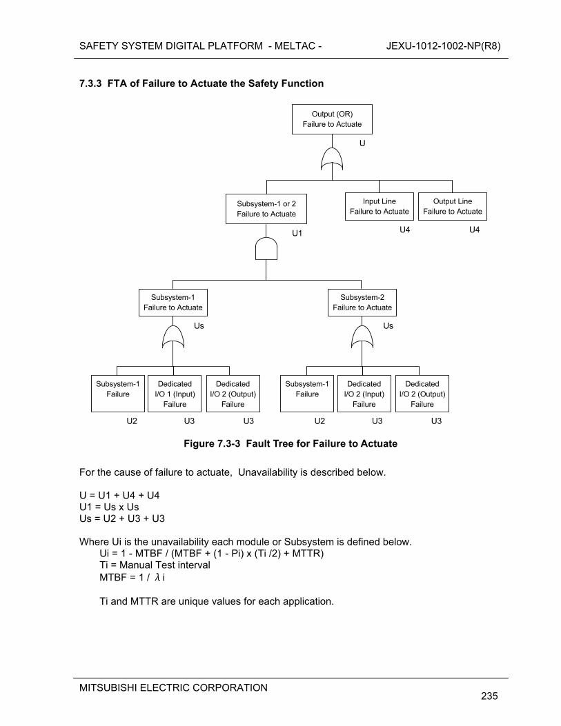
SAFETY SYSTEM DIGITAL PLATFORM - MELTAC - JEXU-1012-1002-NP(R8)
MITSUBISHI ELECTRIC CORPORATION
235
7.3.3 FTA of Failure to Actuate the Safety Function
U1 U4U4
U
Us
Subsystem-1 or 2Failure to Actuate
Output (OR) Failure to Actuate
Subsystem-1 Failure to Actuate
Output Line Failure to Actuate
Input Line Failure to Actuate
Subsystem-1 Failure
Dedicated I/O 1 (Input)
Failure
DedicatedI/O 2 (Output)
Failure
Us
Subsystem-2 Failure to Actuate
Subsystem-1Failure
DedicatedI/O 2 (Input)
Failure
Dedicated I/O 2 (Output)
Failure
U2 U3 U3 U2 U3 U3
Figure 7.3-3 Fault Tree for Failure to Actuate
For the cause of failure to actuate, Unavailability is described below. U = U1 + U4 + U4 U1 = Us x Us Us = U2 + U3 + U3 Where Ui is the unavailability each module or Subsystem is defined below.
Ui = 1 - MTBF / (MTBF + (1 - Pi) x (Ti /2) + MTTR) Ti = Manual Test interval MTBF = 1 / λi Ti and MTTR are unique values for each application.
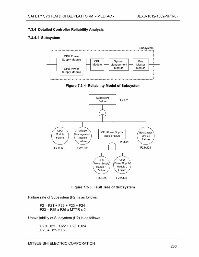
SAFETY SYSTEM DIGITAL PLATFORM - MELTAC - JEXU-1012-1002-NP(R8)
MITSUBISHI ELECTRIC CORPORATION
236
7.3.4 Detailed Controller Reliability Analysis 7.3.4.1 Subsystem
Bus Master Module
System Management
Module
CPU Module
CPU Power Supply Module
CPU Power Supply Module
Subsystem
Figure 7.3-4 Reliability Model of Subsystem
F21/U21 F24/U24
F2/U2 Subsystem
Failure
CPU Power Supply
Module-1 Failure
CPU Power Supply
Module-2 Failure
CPU Power SupplyModule Failure
CPU Module Failure
F23/U23
F25/U25 F25/U25
Bus Master Module Failure
F22/U22
System Management
Module Failure
Figure 7.3-5 Fault Tree of Subsystem
Failure rate of Subsystem (F2) is as follows.
F2 = F21 + F22 + F23 + F24 F23 = F25 x F25 x MTTR x 2
Unavailability of Subsystem (U2) is as follows. U2 = U21 + U22 + U23 +U24 U23 = U25 x U25
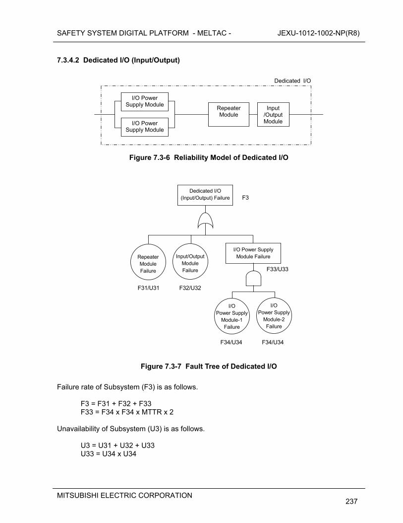
SAFETY SYSTEM DIGITAL PLATFORM - MELTAC - JEXU-1012-1002-NP(R8)
MITSUBISHI ELECTRIC CORPORATION
237
7.3.4.2 Dedicated I/O (Input/Output)
Input /OutputModule
Repeater Module
I/O Power Supply Module
I/O Power Supply Module
Dedicated I/O
Figure 7.3-6 Reliability Model of Dedicated I/O
Repeater Module Failure
Input/OutputModule Failure
Dedicated I/O (Input/Output) Failure F3
F31/U31 F32/U32
I/O Power Supply
Module-1 Failure
I/O Power Supply
Module-2 Failure
I/O Power SupplyModule Failure
F33/U33
F34/U34 F34/U34
Figure 7.3-7 Fault Tree of Dedicated I/O
Failure rate of Subsystem (F3) is as follows.
F3 = F31 + F32 + F33 F33 = F34 x F34 x MTTR x 2
Unavailability of Subsystem (U3) is as follows. U3 = U31 + U32 + U33 U33 = U34 x U34
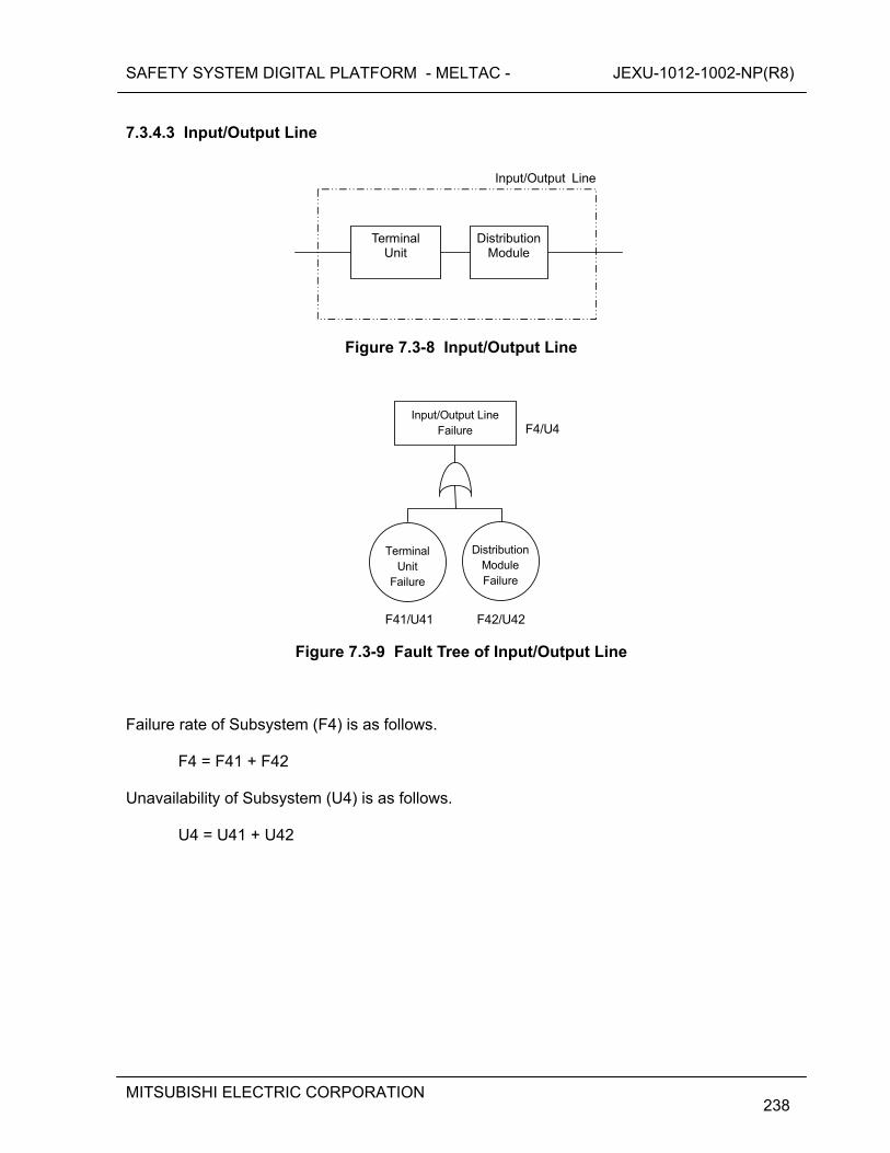
SAFETY SYSTEM DIGITAL PLATFORM - MELTAC - JEXU-1012-1002-NP(R8)
MITSUBISHI ELECTRIC CORPORATION
238
7.3.4.3 Input/Output Line
DistributionModule
Terminal Unit
Input/Output Line
Figure 7.3-8 Input/Output Line
Terminal Unit
Failure
DistributionModule Failure
Input/Output Line Failure F4/U4
F41/U41 F42/U42
Figure 7.3-9 Fault Tree of Input/Output Line
Failure rate of Subsystem (F4) is as follows.
F4 = F41 + F42 Unavailability of Subsystem (U4) is as follows. U4 = U41 + U42
SAFETY SYSTEM DIGITAL PLATFORM - MELTAC - JEXU-1012-1002-NP(R8)
MITSUBISHI ELECTRIC CORPORATION
239
7.4 Failure Mode and Effects Analysis (FMEA) This section describes the method for conducting the FMEA, which is the method of determining the failure mode for each type of MELTAC Module and the resulting effects at the Controller level. The effects of failures at the system application level are described in the Safety I&C System Description and Design Process Technical Report for the US-APWR DCD. The method of conducting the FMEA is as follows:.
Module circuits are divided into function blocks. Determine the failure modes of the function block. Determine the state(s) of the module output(s) caused by the failure mode(s) of the
function block. Determine the effects at the Controller level based on the module output failure states.
For a module to be acceptable for use in the CPU Chassis, failures in the function blocks that may affect the control function must be detected either by the self-diagnosis function inside the module or by the self-diagnosis function through a combination of modules. The parts that do not affect the control function are identified through the FMEA, such as RS-232C communication port witch is used only for CPU Module debugging, For a module to be acceptable for use in the I/O Chassis, failures in the parts that may affect the control function must be detected either by the self-diagnosis function of the CPU Module or by the application software. For instance, if the relay contact of the relay output module suffers a seizure failure, it cannot be detected by the self-diagnosis function of the controller. However, this failure can be detected by the application software when the component is actuated either automatically or manually. The FMEA method and acceptance criteria described in this section apply to all MELTAC modules. The same method and acceptance criteria will also be used for any module upgrades or new MELTAC modules.
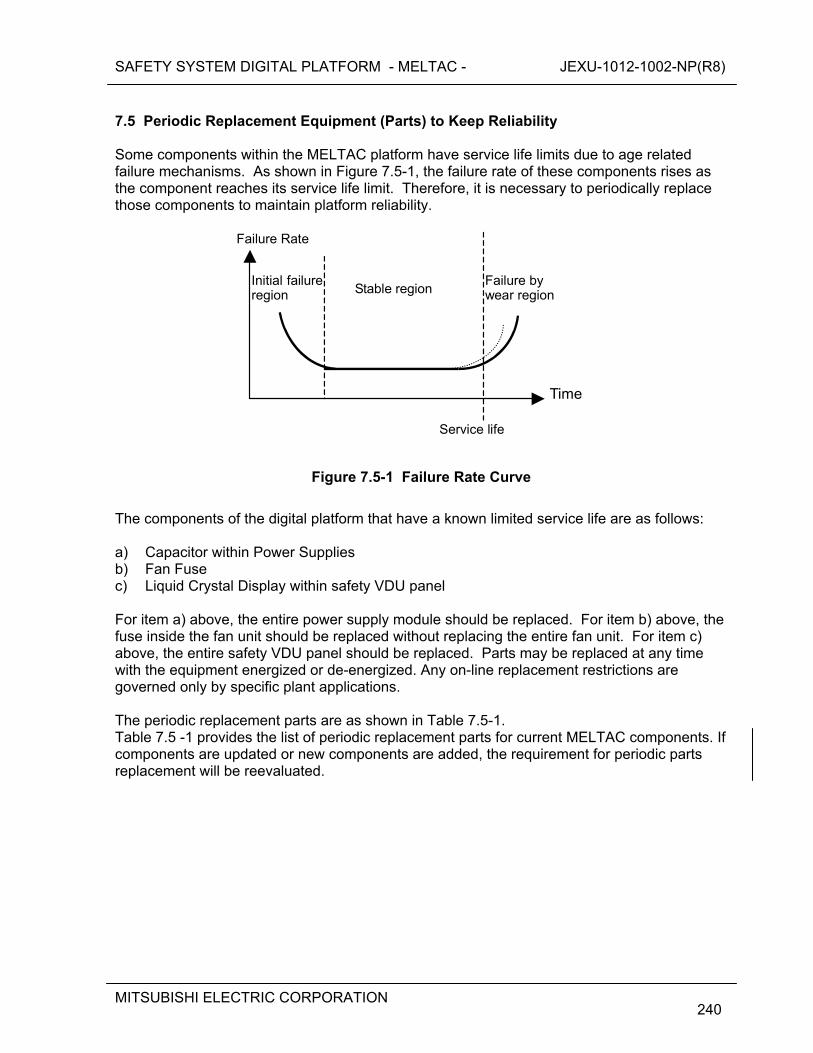
SAFETY SYSTEM DIGITAL PLATFORM - MELTAC - JEXU-1012-1002-NP(R8)
MITSUBISHI ELECTRIC CORPORATION
240
7.5 Periodic Replacement Equipment (Parts) to Keep Reliability Some components within the MELTAC platform have service life limits due to age related failure mechanisms. As shown in Figure 7.5-1, the failure rate of these components rises as the component reaches its service life limit. Therefore, it is necessary to periodically replace those components to maintain platform reliability.
Stable regionFailure by wear region
Initial failure region
Service life
Time
Failure Rate
Figure 7.5-1 Failure Rate Curve
The components of the digital platform that have a known limited service life are as follows: a) Capacitor within Power Supplies b) Fan Fuse c) Liquid Crystal Display within safety VDU panel For item a) above, the entire power supply module should be replaced. For item b) above, the fuse inside the fan unit should be replaced without replacing the entire fan unit. For item c) above, the entire safety VDU panel should be replaced. Parts may be replaced at any time with the equipment energized or de-energized. Any on-line replacement restrictions are governed only by specific plant applications. The periodic replacement parts are as shown in Table 7.5-1. Table 7.5 -1 provides the list of periodic replacement parts for current MELTAC components. If components are updated or new components are added, the requirement for periodic parts replacement will be reevaluated.
SAFETY SYSTEM DIGITAL PLATFORM - MELTAC - JEXU-1012-1002-NP(R8)
MITSUBISHI ELECTRIC CORPORATION
241
Table 7.5-1 List of Periodic Replacement Parts
For the power supplies, the estimated lifetime of the internal electrolytic capacitor was calculated based on the Arrhenius equation. For the fuses in the fan assemblies, the estimated lifetime was determined by experience for the condition under which the fuse is actually used. The replacement interval of all of the above components was determined based on applying a 20% conservatism factor to the estimated lifetimes of these subparts. The components described above have age related failure mechanisms, however none of these aging mechanisms would significantly affect the equipment’s susceptibility to failure during any of the equipment qualification tests described in Section 5. Therefore there is no age related preconditioning prior to the qualification tests. Other components in the MELTAC platform have no known age related failure mechanisms, therefore replacement only occurs at the time of a random failure. 7.6 Performance history of self-diagnosis function [
SAFETY SYSTEM DIGITAL PLATFORM - MELTAC - JEXU-1012-1002-NP(R8)
MITSUBISHI ELECTRIC CORPORATION
242
]
Table 7.6-1 Number of failures
[
]
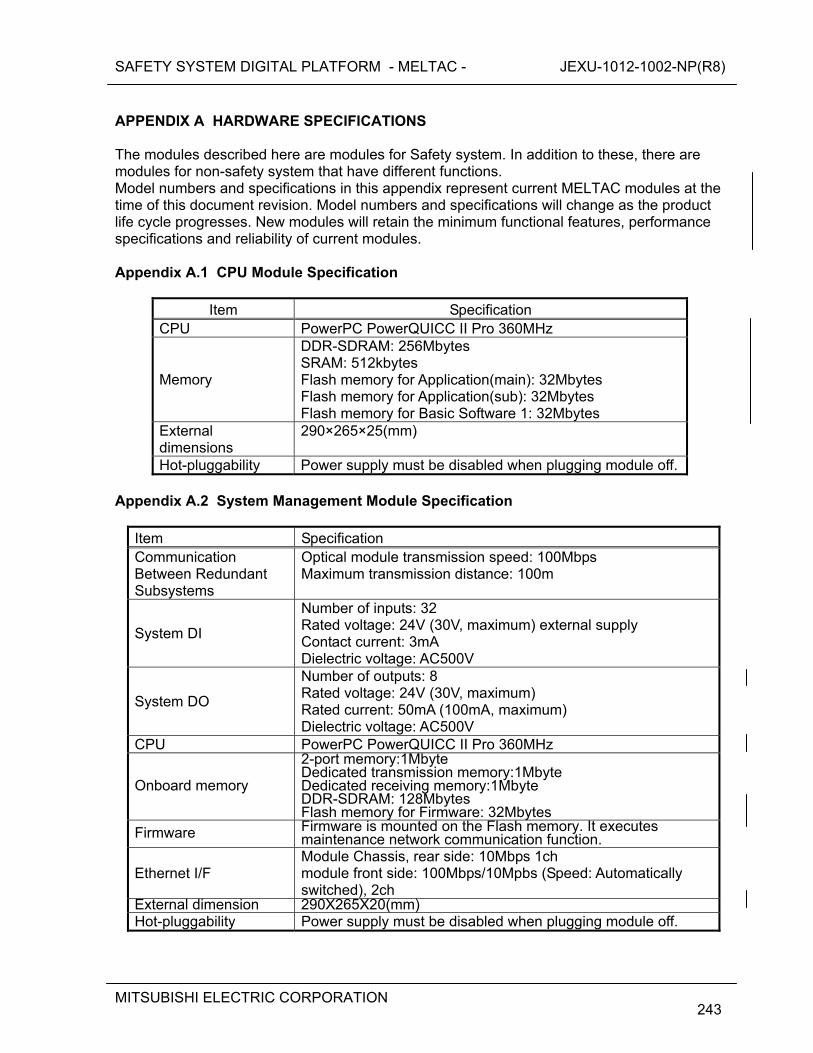
SAFETY SYSTEM DIGITAL PLATFORM - MELTAC - JEXU-1012-1002-NP(R8)
MITSUBISHI ELECTRIC CORPORATION
243
APPENDIX A HARDWARE SPECIFICATIONS The modules described here are modules for Safety system. In addition to these, there are modules for non-safety system that have different functions. Model numbers and specifications in this appendix represent current MELTAC modules at the time of this document revision. Model numbers and specifications will change as the product life cycle progresses. New modules will retain the minimum functional features, performance specifications and reliability of current modules. Appendix A.1 CPU Module Specification
Item Specification CPU PowerPC PowerQUICC II Pro 360MHz
Memory
DDR-SDRAM: 256Mbytes SRAM: 512kbytes Flash memory for Application(main): 32Mbytes Flash memory for Application(sub): 32Mbytes Flash memory for Basic Software 1: 32Mbytes
External dimensions
290×265×25(mm)
Hot-pluggability Power supply must be disabled when plugging module off. Appendix A.2 System Management Module Specification
Item Specification Communication Between Redundant Subsystems
Optical module transmission speed: 100Mbps Maximum transmission distance: 100m
System DI
Number of inputs: 32 Rated voltage: 24V (30V, maximum) external supply Contact current: 3mA Dielectric voltage: AC500V
System DO
Number of outputs: 8 Rated voltage: 24V (30V, maximum) Rated current: 50mA (100mA, maximum) Dielectric voltage: AC500V
CPU PowerPC PowerQUICC II Pro 360MHz
Onboard memory
2-port memory:1Mbyte Dedicated transmission memory:1Mbyte Dedicated receiving memory:1Mbyte DDR-SDRAM: 128Mbytes Flash memory for Firmware: 32Mbytes
Firmware Firmware is mounted on the Flash memory. It executes maintenance network communication function.
Ethernet I/F Module Chassis, rear side: 10Mbps 1ch module front side: 100Mbps/10Mpbs (Speed: Automatically switched), 2ch
External dimension 290X265X20(mm) Hot-pluggability Power supply must be disabled when plugging module off.
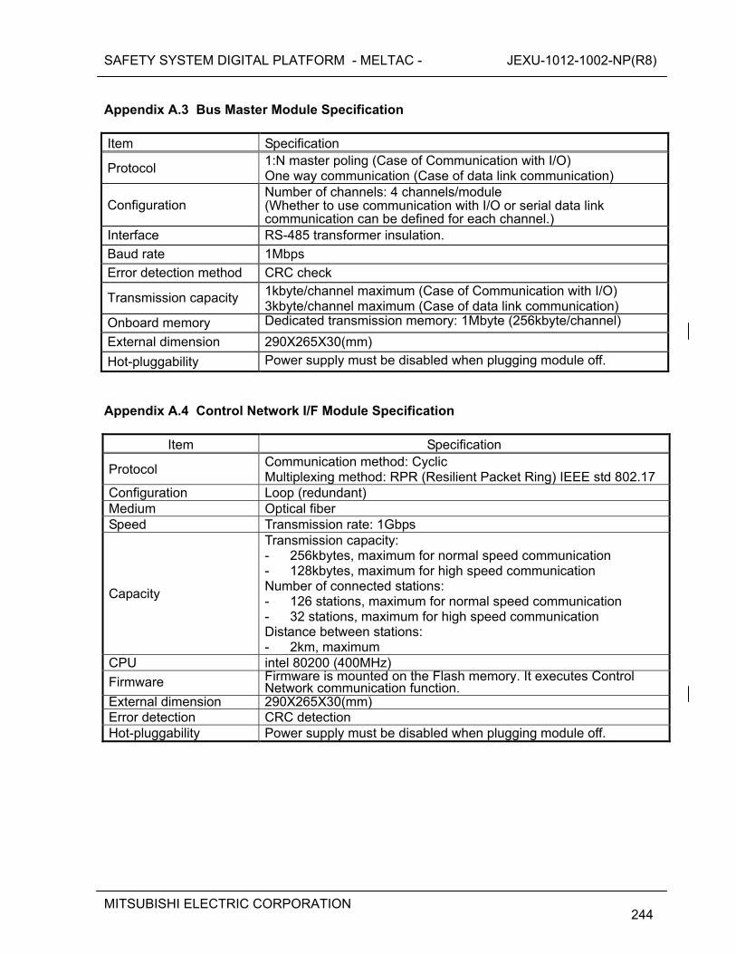
SAFETY SYSTEM DIGITAL PLATFORM - MELTAC - JEXU-1012-1002-NP(R8)
MITSUBISHI ELECTRIC CORPORATION
244
Appendix A.3 Bus Master Module Specification
Item Specification
Protocol 1:N master poling (Case of Communication with I/O) One way communication (Case of data link communication)
Configuration Number of channels: 4 channels/module (Whether to use communication with I/O or serial data link communication can be defined for each channel.)
Interface RS-485 transformer insulation.
Baud rate 1Mbps
Error detection method CRC check
Transmission capacity 1kbyte/channel maximum (Case of Communication with I/O) 3kbyte/channel maximum (Case of data link communication)
Onboard memory Dedicated transmission memory: 1Mbyte (256kbyte/channel)
External dimension 290X265X30(mm)
Hot-pluggability Power supply must be disabled when plugging module off.
Appendix A.4 Control Network I/F Module Specification
Item Specification
Protocol Communication method: Cyclic Multiplexing method: RPR (Resilient Packet Ring) IEEE std 802.17
Configuration Loop (redundant) Medium Optical fiber Speed Transmission rate: 1Gbps
Capacity
Transmission capacity: - 256kbytes, maximum for normal speed communication - 128kbytes, maximum for high speed communication Number of connected stations: - 126 stations, maximum for normal speed communication - 32 stations, maximum for high speed communication Distance between stations: - 2km, maximum
CPU intel 80200 (400MHz)
Firmware Firmware is mounted on the Flash memory. It executes Control Network communication function.
External dimension 290X265X30(mm) Error detection CRC detection Hot-pluggability Power supply must be disabled when plugging module off.
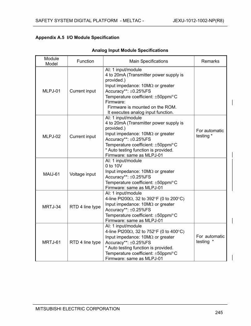
SAFETY SYSTEM DIGITAL PLATFORM - MELTAC - JEXU-1012-1002-NP(R8)
MITSUBISHI ELECTRIC CORPORATION
245
Appendix A.5 I/O Module Specification
Analog Input Module Specifications
Module Model
Function Main Specifications Remarks
MLPJ-01 Current input
AI: 1 input/module 4 to 20mA (Transmitter power supply is provided.) Input impedance: 10M or greater Accuracy**: 0.25%FS Temperature coefficient: 50ppm/C Firmware: Firmware is mounted on the ROM. It executes analog input function.
MLPJ-02 Current input
AI: 1 input/module 4 to 20mA (Transmitter power supply is provided.) Input impedance: 10M or greater Accuracy**: 0.25%FS Temperature coefficient: 50ppm/C * Auto testing function is provided. Firmware: same as MLPJ-01
For automatic testing *
MAIJ-61 Voltage input
AI: 1 input/module 0 to 10V Input impedance: 10M or greater Accuracy**: 0.25%FS Temperature coefficient: 50ppm/C Firmware: same as MLPJ-01
MRTJ-34 RTD 4 line type
AI: 1 input/module 4-line Pt200, 32 to 392F (0 to 200C) Input impedance: 10M or greater Accuracy**: 0.25%FS Temperature coefficient: 50ppm/C Firmware: same as MLPJ-01
MRTJ-61 RTD 4 line type
AI: 1 input/module 4-line Pt200, 32 to 752F (0 to 400C) Input impedance: 10M or greater Accuracy**: 0.25%FS * Auto testing function is provided. Temperature coefficient: 50ppm/C Firmware: same as MLPJ-01
For automatic testing *
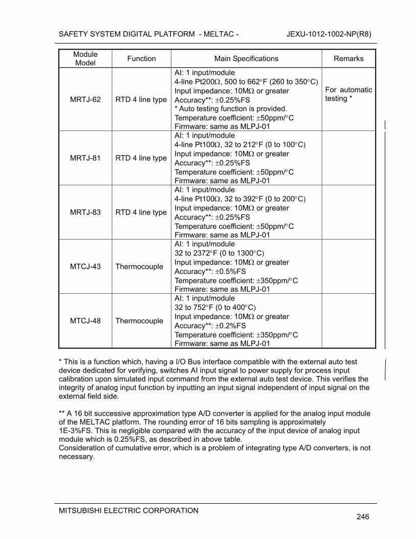
SAFETY SYSTEM DIGITAL PLATFORM - MELTAC - JEXU-1012-1002-NP(R8)
MITSUBISHI ELECTRIC CORPORATION
246
Module Model
Function Main Specifications Remarks
MRTJ-62 RTD 4 line type
AI: 1 input/module 4-line Pt200, 500 to 662F (260 to 350C) Input impedance: 10M or greater Accuracy**: 0.25%FS * Auto testing function is provided. Temperature coefficient: 50ppm/C Firmware: same as MLPJ-01
For automatic testing *
MRTJ-81 RTD 4 line type
AI: 1 input/module 4-line Pt100, 32 to 212F (0 to 100C) Input impedance: 10M or greater Accuracy**: 0.25%FS Temperature coefficient: 50ppm/C Firmware: same as MLPJ-01
MRTJ-83 RTD 4 line type
AI: 1 input/module 4-line Pt100, 32 to 392F (0 to 200C) Input impedance: 10M or greater Accuracy**: 0.25%FS Temperature coefficient: 50ppm/C Firmware: same as MLPJ-01
MTCJ-43 Thermocouple
AI: 1 input/module 32 to 2372F (0 to 1300C) Input impedance: 10M or greater Accuracy**: 0.5%FS Temperature coefficient: 350ppm/C Firmware: same as MLPJ-01
MTCJ-48 Thermocouple
AI: 1 input/module 32 to 752F (0 to 400C) Input impedance: 10M or greater Accuracy**: 0.2%FS Temperature coefficient: 350ppm/C Firmware: same as MLPJ-01
* This is a function which, having a I/O Bus interface compatible with the external auto test device dedicated for verifying, switches AI input signal to power supply for process input calibration upon simulated input command from the external auto test device. This verifies the integrity of analog input function by inputting an input signal independent of input signal on the external field side. ** A 16 bit successive approximation type A/D converter is applied for the analog input module of the MELTAC platform. The rounding error of 16 bits sampling is approximately 1E-3%FS. This is negligible compared with the accuracy of the input device of analog input module which is 0.25%FS, as described in above table. Consideration of cumulative error, which is a problem of integrating type A/D converters, is not necessary.
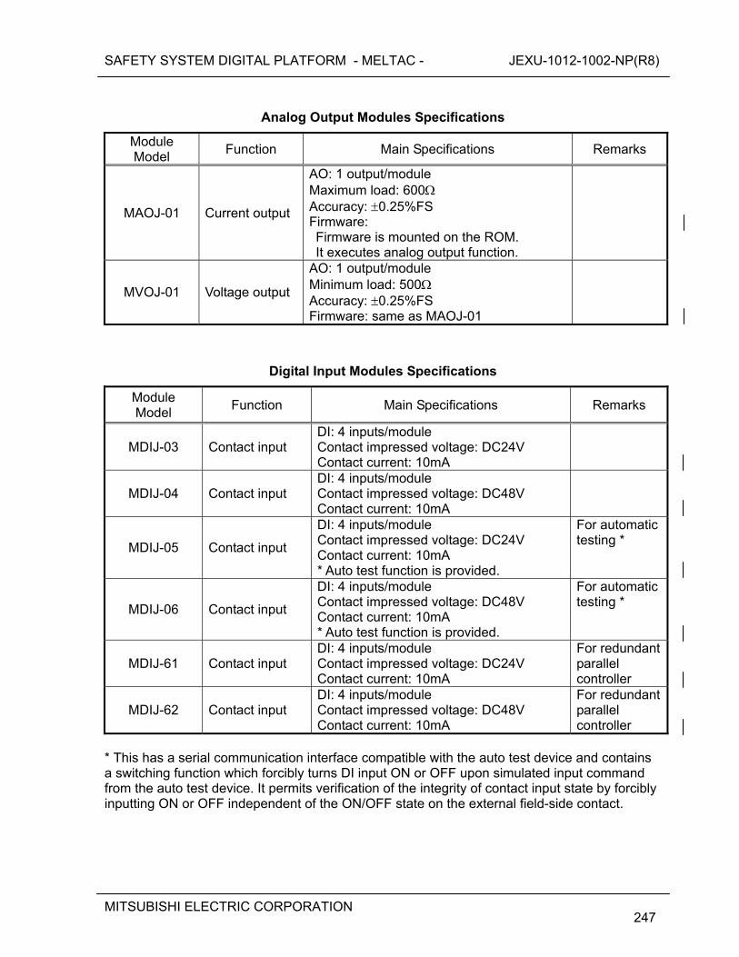
SAFETY SYSTEM DIGITAL PLATFORM - MELTAC - JEXU-1012-1002-NP(R8)
MITSUBISHI ELECTRIC CORPORATION
247
Analog Output Modules Specifications
Module Model
Function Main Specifications Remarks
MAOJ-01 Current output
AO: 1 output/module Maximum load: 600 Accuracy: 0.25%FS Firmware: Firmware is mounted on the ROM. It executes analog output function.
MVOJ-01 Voltage output
AO: 1 output/module Minimum load: 500 Accuracy: 0.25%FS Firmware: same as MAOJ-01
Digital Input Modules Specifications
Module Model
Function Main Specifications Remarks
MDIJ-03 Contact input DI: 4 inputs/module Contact impressed voltage: DC24V Contact current: 10mA
MDIJ-04 Contact input DI: 4 inputs/module Contact impressed voltage: DC48V Contact current: 10mA
MDIJ-05 Contact input
DI: 4 inputs/module Contact impressed voltage: DC24V Contact current: 10mA * Auto test function is provided.
For automatic testing *
MDIJ-06 Contact input
DI: 4 inputs/module Contact impressed voltage: DC48V Contact current: 10mA * Auto test function is provided.
For automatic testing *
MDIJ-61 Contact input DI: 4 inputs/module Contact impressed voltage: DC24V Contact current: 10mA
For redundant parallel controller
MDIJ-62 Contact input DI: 4 inputs/module Contact impressed voltage: DC48V Contact current: 10mA
For redundant parallel controller
* This has a serial communication interface compatible with the auto test device and contains a switching function which forcibly turns DI input ON or OFF upon simulated input command from the auto test device. It permits verification of the integrity of contact input state by forcibly inputting ON or OFF independent of the ON/OFF state on the external field-side contact.
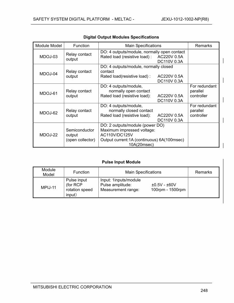
SAFETY SYSTEM DIGITAL PLATFORM - MELTAC - JEXU-1012-1002-NP(R8)
MITSUBISHI ELECTRIC CORPORATION
248
Digital Output Modules Specifications
Module Model Function Main Specifications Remarks
MDOJ-03 Relay contact output
DO: 4 outputs/module, normally open contact Rated load (resistive load) : AC220V 0.5A DC110V 0.3A
MDOJ-04 Relay contact output
DO: 4 outputs/module, normally closed contact Rated load(resistive load) : AC220V 0.5A DC110V 0.3A
MDOJ-61 Relay contact output
DO: 4 outputs/module, normally open contact
Rated load (resistive load): AC220V 0.5A DC110V 0.3A
For redundant parallel controller
MDOJ-62 Relay contact output
DO: 4 outputs/module, normally closed contact
Rated load (resistive load): AC220V 0.5A DC110V 0.3A
For redundant parallel controller
MDOJ-22 Semiconductor output (open collector)
DO: 2 outputs/module (power DO) Maximum impressed voltage: AC110V/DC125V Output current:1A (continuous) 6A(100msec)
10A(20msec)
Pulse Input Module
Module Model
Function Main Specifications Remarks
MPIJ-11
Pulse input (for RCP rotation speed input)
Input: 1inputs/module Pulse amplitude: ±0.5V - ±60V Measurement range: 100rpm - 1500rpm
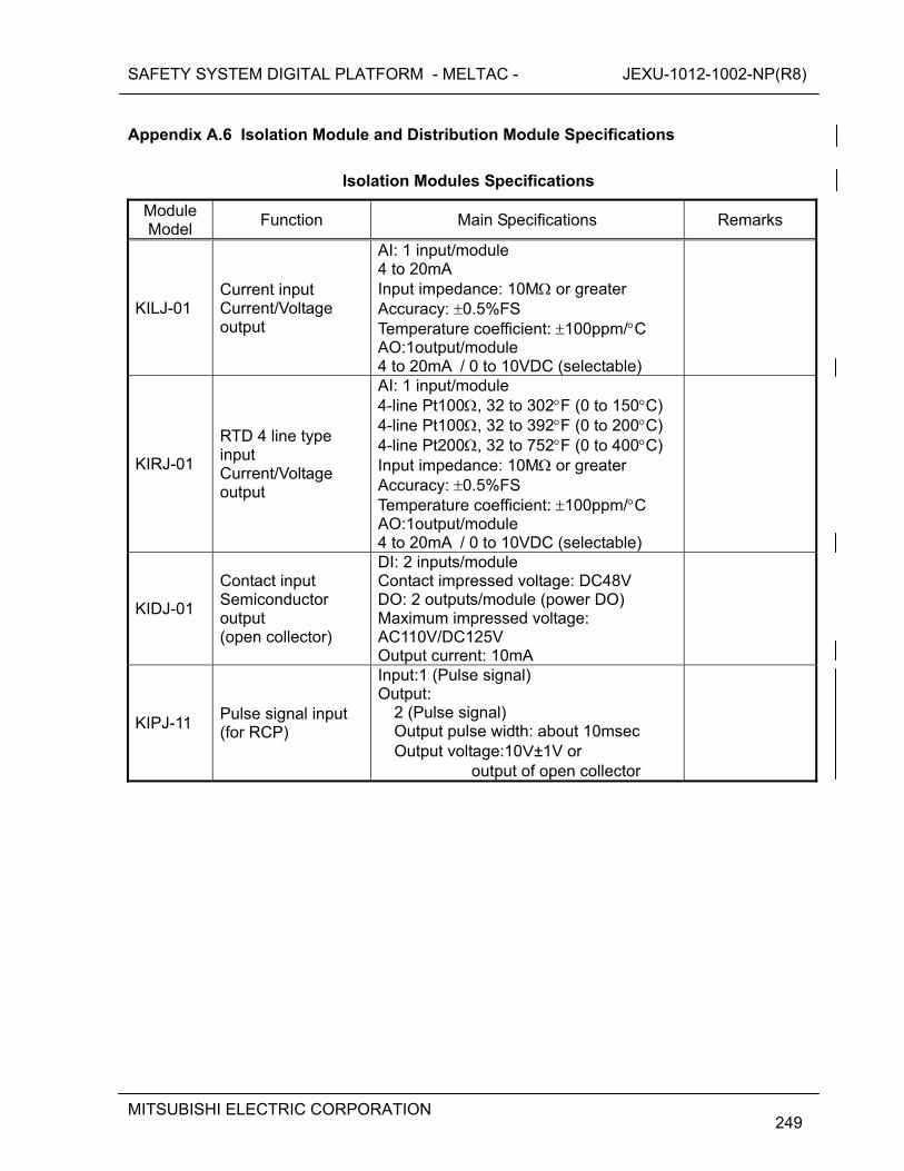
SAFETY SYSTEM DIGITAL PLATFORM - MELTAC - JEXU-1012-1002-NP(R8)
MITSUBISHI ELECTRIC CORPORATION
249
Appendix A.6 Isolation Module and Distribution Module Specifications
Isolation Modules Specifications
Module Model
Function Main Specifications Remarks
KILJ-01 Current input Current/Voltage output
AI: 1 input/module 4 to 20mA Input impedance: 10M or greater Accuracy: 0.5%FS Temperature coefficient: 100ppm/C AO:1output/module 4 to 20mA / 0 to 10VDC (selectable)
KIRJ-01
RTD 4 line type input Current/Voltage output
AI: 1 input/module 4-line Pt100, 32 to 302F (0 to 150C) 4-line Pt100, 32 to 392F (0 to 200C) 4-line Pt200, 32 to 752F (0 to 400C) Input impedance: 10M or greater Accuracy: 0.5%FS Temperature coefficient: 100ppm/C AO:1output/module 4 to 20mA / 0 to 10VDC (selectable)
KIDJ-01
Contact input Semiconductor output (open collector)
DI: 2 inputs/module Contact impressed voltage: DC48V DO: 2 outputs/module (power DO) Maximum impressed voltage: AC110V/DC125V Output current: 10mA
KIPJ-11 Pulse signal input (for RCP)
Input:1 (Pulse signal) Output:
2 (Pulse signal) Output pulse width: about 10msec Output voltage:10V±1V or
output of open collector
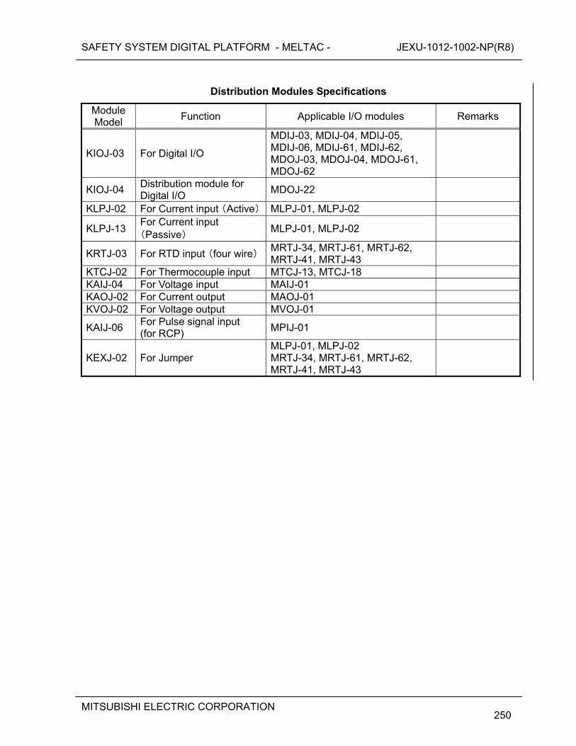
SAFETY SYSTEM DIGITAL PLATFORM - MELTAC - JEXU-1012-1002-NP(R8)
MITSUBISHI ELECTRIC CORPORATION
250
Distribution Modules Specifications
Module Model
Function Applicable I/O modules Remarks
KIOJ-03 For Digital I/O
MDIJ-03, MDIJ-04, MDIJ-05, MDIJ-06, MDIJ-61, MDIJ-62, MDOJ-03, MDOJ-04, MDOJ-61, MDOJ-62
KIOJ-04 Distribution module for Digital I/O
MDOJ-22
KLPJ-02 For Current input (Active) MLPJ-01, MLPJ-02
KLPJ-13 For Current input (Passive)
MLPJ-01, MLPJ-02
KRTJ-03 For RTD input (four wire)MRTJ-34, MRTJ-61, MRTJ-62, MRTJ-41, MRTJ-43
KTCJ-02 For Thermocouple input MTCJ-13, MTCJ-18 KAIJ-04 For Voltage input MAIJ-01 KAOJ-02 For Current output MAOJ-01 KVOJ-02 For Voltage output MVOJ-01
KAIJ-06 For Pulse signal input (for RCP)
MPIJ-01
KEXJ-02 For Jumper MLPJ-01, MLPJ-02 MRTJ-34, MRTJ-61, MRTJ-62, MRTJ-41, MRTJ-43
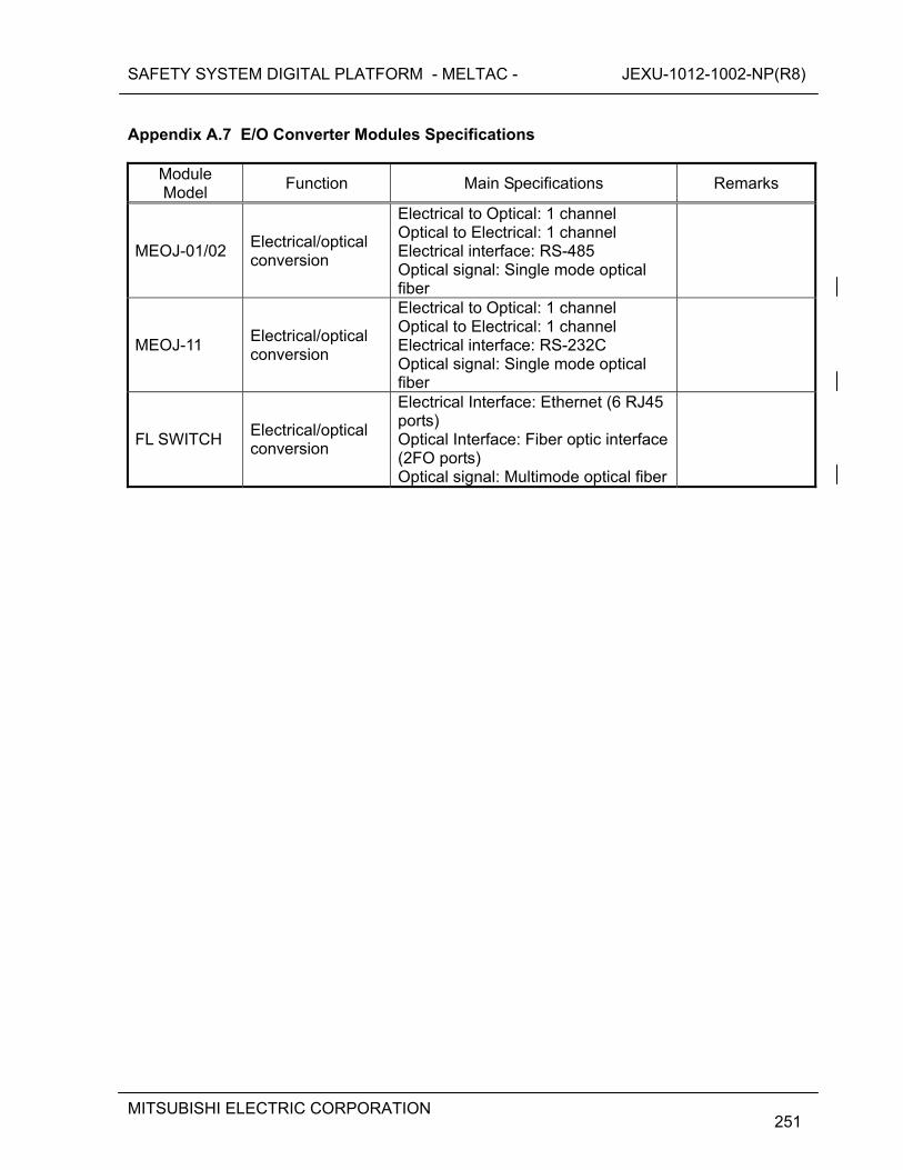
SAFETY SYSTEM DIGITAL PLATFORM - MELTAC - JEXU-1012-1002-NP(R8)
MITSUBISHI ELECTRIC CORPORATION
251
Appendix A.7 E/O Converter Modules Specifications
Module Model
Function Main Specifications Remarks
MEOJ-01/02 Electrical/optical conversion
Electrical to Optical: 1 channel Optical to Electrical: 1 channel Electrical interface: RS-485 Optical signal: Single mode optical fiber
MEOJ-11 Electrical/optical conversion
Electrical to Optical: 1 channel Optical to Electrical: 1 channel Electrical interface: RS-232C Optical signal: Single mode optical fiber
FL SWITCH Electrical/optical conversion
Electrical Interface: Ethernet (6 RJ45 ports) Optical Interface: Fiber optic interface (2FO ports) Optical signal: Multimode optical fiber
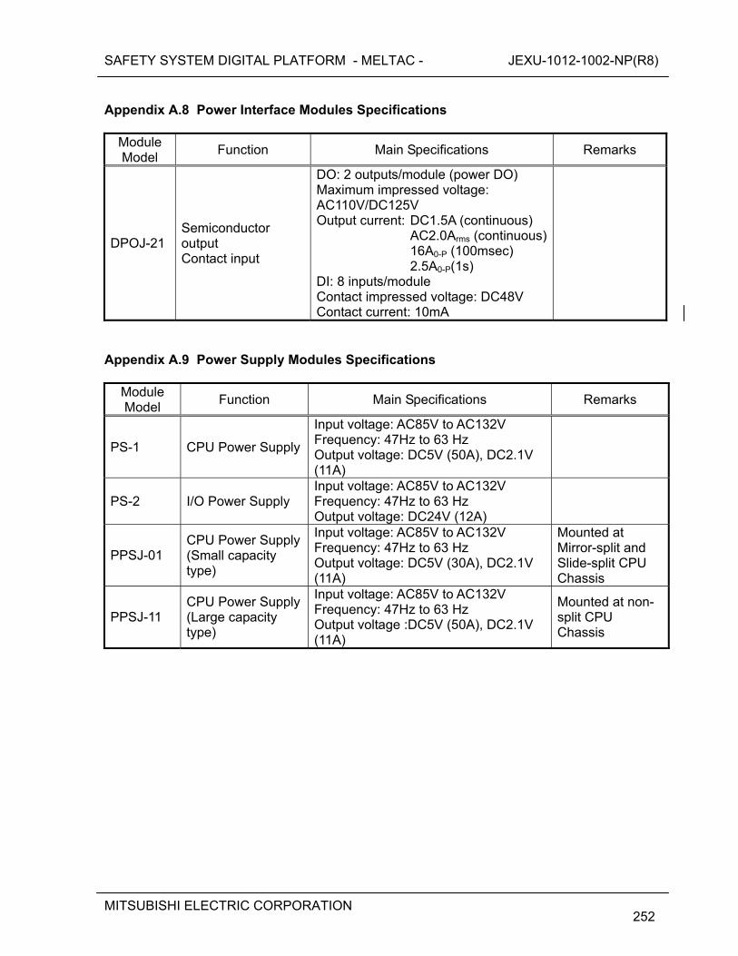
SAFETY SYSTEM DIGITAL PLATFORM - MELTAC - JEXU-1012-1002-NP(R8)
MITSUBISHI ELECTRIC CORPORATION
252
Appendix A.8 Power Interface Modules Specifications
Module Model
Function Main Specifications Remarks
DPOJ-21 Semiconductor output Contact input
DO: 2 outputs/module (power DO) Maximum impressed voltage: AC110V/DC125V Output current: DC1.5A (continuous)
AC2.0Arms (continuous) 16A0-P (100msec) 2.5A0-P(1s)
DI: 8 inputs/module Contact impressed voltage: DC48V Contact current: 10mA
Appendix A.9 Power Supply Modules Specifications
Module Model
Function Main Specifications Remarks
PS-1 CPU Power Supply
Input voltage: AC85V to AC132V Frequency: 47Hz to 63 Hz Output voltage: DC5V (50A), DC2.1V (11A)
PS-2 I/O Power Supply Input voltage: AC85V to AC132V Frequency: 47Hz to 63 Hz Output voltage: DC24V (12A)
PPSJ-01 CPU Power Supply (Small capacity type)
Input voltage: AC85V to AC132V Frequency: 47Hz to 63 Hz Output voltage: DC5V (30A), DC2.1V (11A)
Mounted at Mirror-split and Slide-split CPU Chassis
PPSJ-11 CPU Power Supply(Large capacity type)
Input voltage: AC85V to AC132V Frequency: 47Hz to 63 Hz Output voltage :DC5V (50A), DC2.1V (11A)
Mounted at non-split CPU Chassis
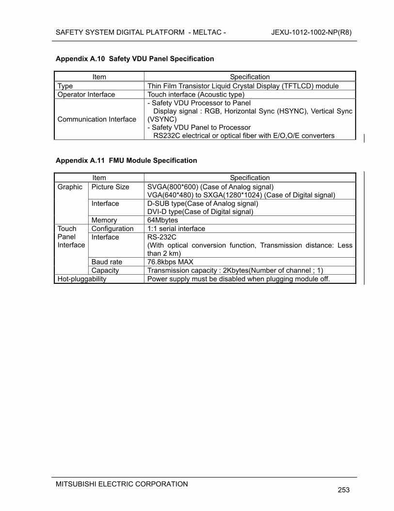
SAFETY SYSTEM DIGITAL PLATFORM - MELTAC - JEXU-1012-1002-NP(R8)
MITSUBISHI ELECTRIC CORPORATION
253
Appendix A.10 Safety VDU Panel Specification
Item Specification Type Thin Film Transistor Liquid Crystal Display (TFTLCD) module Operator Interface Touch interface (Acoustic type)
Communication Interface
- Safety VDU Processor to Panel Display signal : RGB, Horizontal Sync (HSYNC), Vertical Sync (VSYNC) - Safety VDU Panel to Processor RS232C electrical or optical fiber with E/O,O/E converters
Appendix A.11 FMU Module Specification
Item Specification Picture Size SVGA(800*600) (Case of Analog signal)
VGA(640*480) to SXGA(1280*1024) (Case of Digital signal) Interface D-SUB type(Case of Analog signal)
DVI-D type(Case of Digital signal)
Graphic
Memory 64Mbytes Configuration 1:1 serial interface Interface RS-232C
(With optical conversion function, Transmission distance: Less than 2 km)
Baud rate 76.8kbps MAX
Touch Panel Interface
Capacity Transmission capacity : 2Kbytes(Number of channel ; 1) Hot-pluggability Power supply must be disabled when plugging module off.
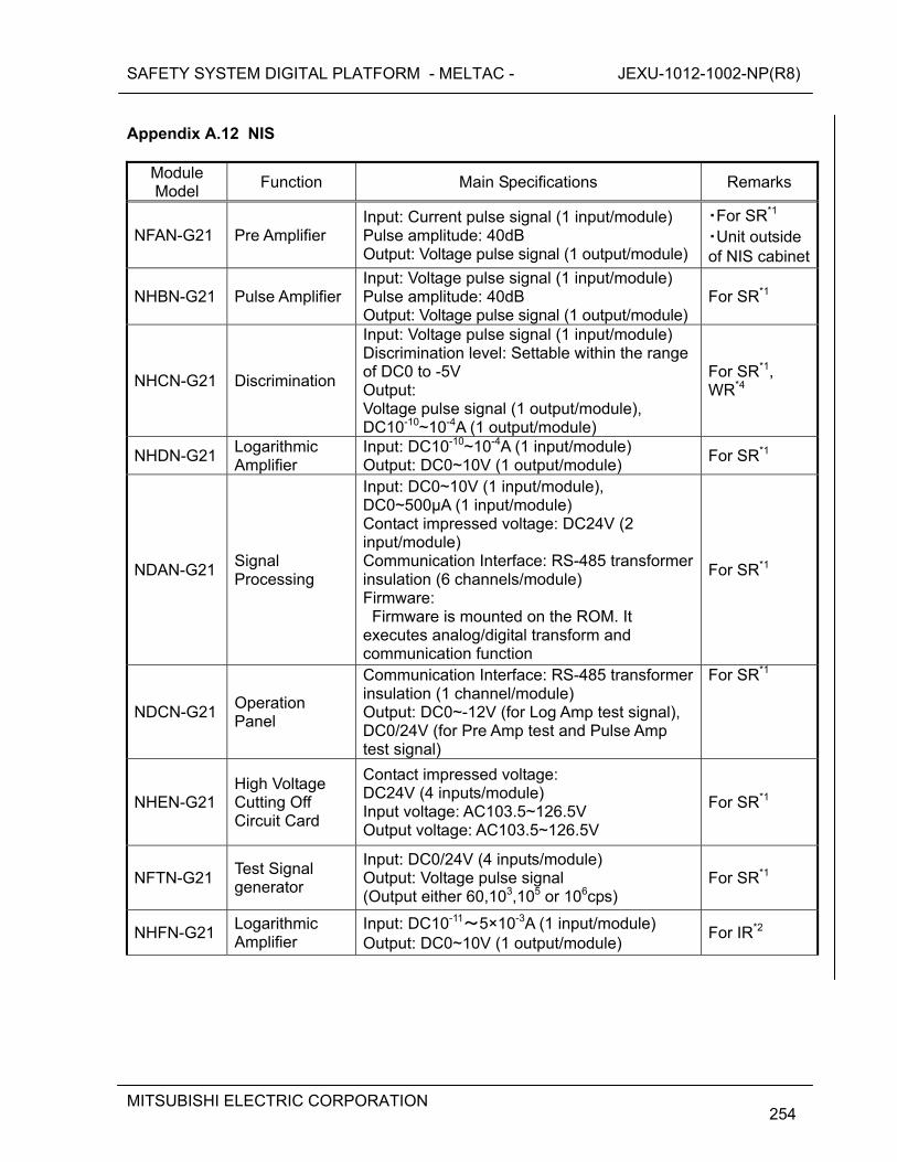
SAFETY SYSTEM DIGITAL PLATFORM - MELTAC - JEXU-1012-1002-NP(R8)
MITSUBISHI ELECTRIC CORPORATION
254
Appendix A.12 NIS
Module Model
Function Main Specifications Remarks
NFAN-G21 Pre Amplifier Input: Current pulse signal (1 input/module) Pulse amplitude: 40dB Output: Voltage pulse signal (1 output/module)
・For SR*1
・Unit outside of NIS cabinet
NHBN-G21 Pulse Amplifier Input: Voltage pulse signal (1 input/module) Pulse amplitude: 40dB Output: Voltage pulse signal (1 output/module)
For SR*1
NHCN-G21 Discrimination
Input: Voltage pulse signal (1 input/module) Discrimination level: Settable within the range of DC0 to -5V Output: Voltage pulse signal (1 output/module), DC10-10~10-4A (1 output/module)
For SR*1, WR*4
NHDN-G21 Logarithmic Amplifier
Input: DC10-10~10-4A (1 input/module) Output: DC0~10V (1 output/module)
For SR*1
NDAN-G21 Signal Processing
Input: DC0~10V (1 input/module), DC0~500μA (1 input/module) Contact impressed voltage: DC24V (2 input/module) Communication Interface: RS-485 transformer insulation (6 channels/module) Firmware: Firmware is mounted on the ROM. It executes analog/digital transform and communication function
For SR*1
NDCN-G21 Operation Panel
Communication Interface: RS-485 transformer insulation (1 channel/module) Output: DC0~-12V (for Log Amp test signal), DC0/24V (for Pre Amp test and Pulse Amp test signal)
For SR*1
NHEN-G21 High Voltage Cutting Off Circuit Card
Contact impressed voltage: DC24V (4 inputs/module) Input voltage: AC103.5~126.5V Output voltage: AC103.5~126.5V
For SR*1
NFTN-G21 Test Signal generator
Input: DC0/24V (4 inputs/module) Output: Voltage pulse signal (Output either 60,103,105 or 106cps)
For SR*1
NHFN-G21 Logarithmic Amplifier
Input: DC10-11~5×10⁻³A (1 input/module) Output: DC0~10V (1 output/module)
For IR*2
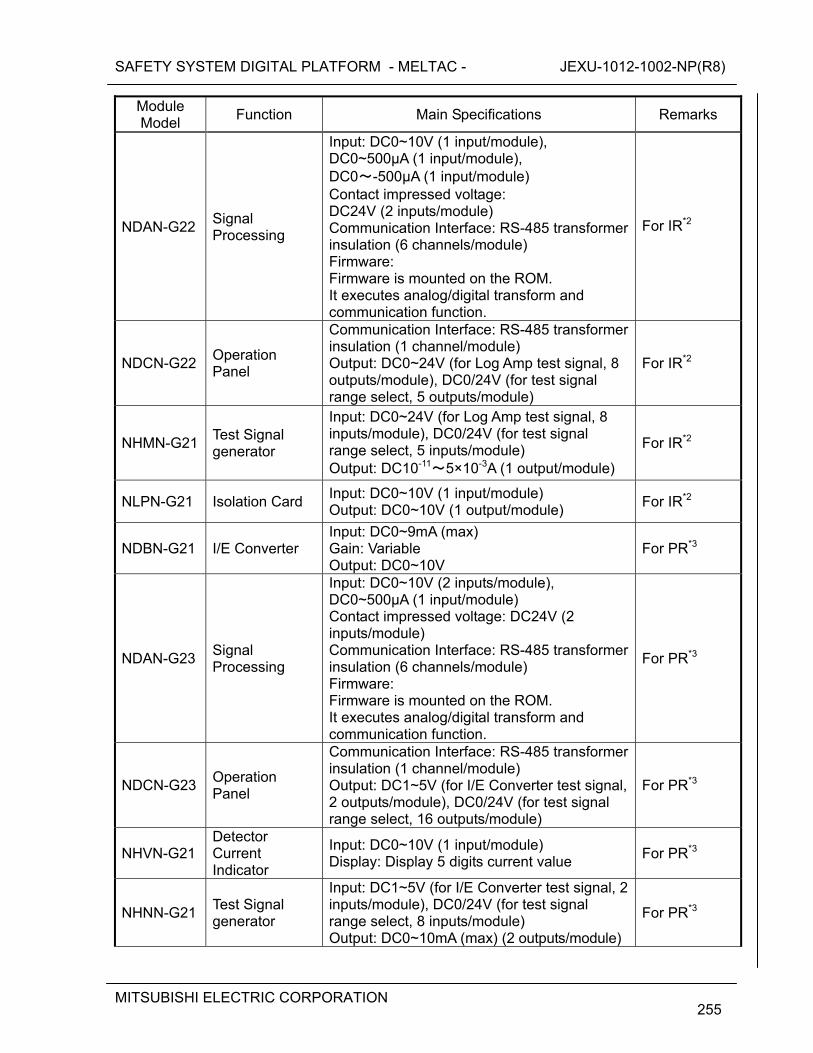
SAFETY SYSTEM DIGITAL PLATFORM - MELTAC - JEXU-1012-1002-NP(R8)
MITSUBISHI ELECTRIC CORPORATION
255
Module Model
Function Main Specifications Remarks
NDAN-G22 Signal Processing
Input: DC0~10V (1 input/module), DC0~500μA (1 input/module), DC0~-500μA (1 input/module) Contact impressed voltage: DC24V (2 inputs/module) Communication Interface: RS-485 transformer insulation (6 channels/module) Firmware: Firmware is mounted on the ROM. It executes analog/digital transform and communication function.
For IR*2
NDCN-G22 Operation Panel
Communication Interface: RS-485 transformer insulation (1 channel/module) Output: DC0~24V (for Log Amp test signal, 8 outputs/module), DC0/24V (for test signal range select, 5 outputs/module)
For IR*2
NHMN-G21 Test Signal generator
Input: DC0~24V (for Log Amp test signal, 8 inputs/module), DC0/24V (for test signal range select, 5 inputs/module) Output: DC10-11~5×10⁻³A (1 output/module)
For IR*2
NLPN-G21 Isolation Card Input: DC0~10V (1 input/module) Output: DC0~10V (1 output/module)
For IR*2
NDBN-G21 I/E Converter Input: DC0~9mA (max) Gain: Variable Output: DC0~10V
For PR*3
NDAN-G23 Signal Processing
Input: DC0~10V (2 inputs/module), DC0~500μA (1 input/module) Contact impressed voltage: DC24V (2 inputs/module) Communication Interface: RS-485 transformer insulation (6 channels/module) Firmware: Firmware is mounted on the ROM. It executes analog/digital transform and communication function.
For PR*3
NDCN-G23 Operation Panel
Communication Interface: RS-485 transformer insulation (1 channel/module) Output: DC1~5V (for I/E Converter test signal, 2 outputs/module), DC0/24V (for test signal range select, 16 outputs/module)
For PR*3
NHVN-G21 Detector Current Indicator
Input: DC0~10V (1 input/module) Display: Display 5 digits current value
For PR*3
NHNN-G21 Test Signal generator
Input: DC1~5V (for I/E Converter test signal, 2 inputs/module), DC0/24V (for test signal range select, 8 inputs/module) Output: DC0~10mA (max) (2 outputs/module)
For PR*3
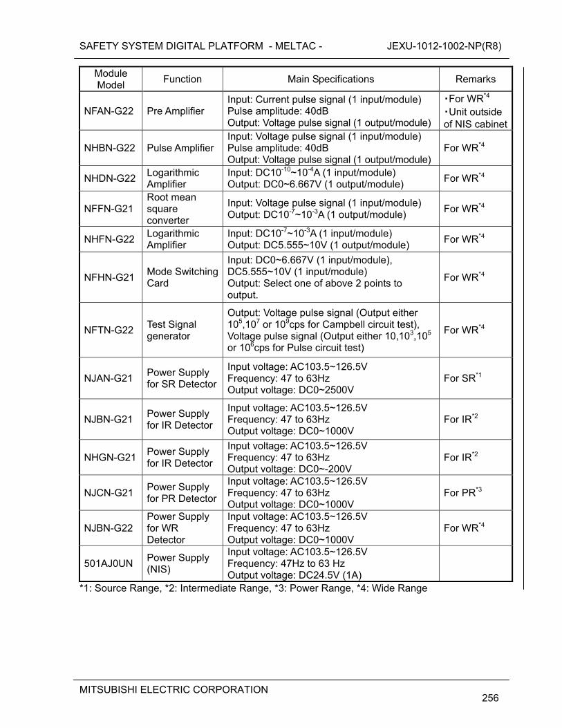
SAFETY SYSTEM DIGITAL PLATFORM - MELTAC - JEXU-1012-1002-NP(R8)
MITSUBISHI ELECTRIC CORPORATION
256
Module Model
Function Main Specifications Remarks
NFAN-G22 Pre Amplifier Input: Current pulse signal (1 input/module) Pulse amplitude: 40dB Output: Voltage pulse signal (1 output/module)
・For WR*4
・Unit outside of NIS cabinet
NHBN-G22 Pulse Amplifier Input: Voltage pulse signal (1 input/module) Pulse amplitude: 40dB Output: Voltage pulse signal (1 output/module)
For WR*4
NHDN-G22 Logarithmic Amplifier
Input: DC10-10~10-4A (1 input/module) Output: DC0~6.667V (1 output/module)
For WR*4
NFFN-G21 Root mean square converter
Input: Voltage pulse signal (1 input/module) Output: DC10-7~10-3A (1 output/module)
For WR*4
NHFN-G22 Logarithmic Amplifier
Input: DC10-7~10-3A (1 input/module) Output: DC5.555~10V (1 output/module)
For WR*4
NFHN-G21 Mode Switching Card
Input: DC0~6.667V (1 input/module), DC5.555~10V (1 input/module) Output: Select one of above 2 points to output.
For WR*4
NFTN-G22 Test Signal generator
Output: Voltage pulse signal (Output either 105,107 or 109cps for Campbell circuit test), Voltage pulse signal (Output either 10,103,105 or 106cps for Pulse circuit test)
For WR*4
NJAN-G21 Power Supply for SR Detector
Input voltage: AC103.5~126.5V Frequency: 47 to 63Hz Output voltage: DC0~2500V
For SR*1
NJBN-G21 Power Supply for IR Detector
Input voltage: AC103.5~126.5V Frequency: 47 to 63Hz Output voltage: DC0~1000V
For IR*2
NHGN-G21 Power Supply for IR Detector
Input voltage: AC103.5~126.5V Frequency: 47 to 63Hz Output voltage: DC0~-200V
For IR*2
NJCN-G21 Power Supply for PR Detector
Input voltage: AC103.5~126.5V Frequency: 47 to 63Hz Output voltage: DC0~1000V
For PR*3
NJBN-G22 Power Supply for WR Detector
Input voltage: AC103.5~126.5V Frequency: 47 to 63Hz Output voltage: DC0~1000V
For WR*4
501AJ0UN Power Supply (NIS)
Input voltage: AC103.5~126.5V Frequency: 47Hz to 63 Hz Output voltage: DC24.5V (1A)
*1: Source Range, *2: Intermediate Range, *3: Power Range, *4: Wide Range
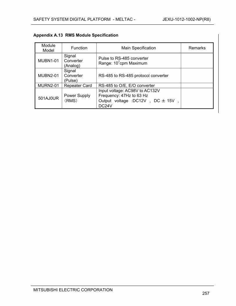
SAFETY SYSTEM DIGITAL PLATFORM - MELTAC - JEXU-1012-1002-NP(R8)
MITSUBISHI ELECTRIC CORPORATION
257
Appendix A.13 RMS Module Specification
Module Model
Function Main Specification Remarks
MUBN1-01 Signal Converter (Analog)
Pulse to RS-485 converter Range: 107cpm Maximum
MUBN2-01 Signal Converter (Pulse)
RS-485 to RS-485 protocol converter
MURN2-01 Repeater Card RS-485 to O/E, E/O converter
501AJ0UR Power Supply (RMS)
Input voltage: AC98V to AC132V Frequency: 47Hz to 63 Hz Output voltage :DC12V , DC ± 15V , DC24V
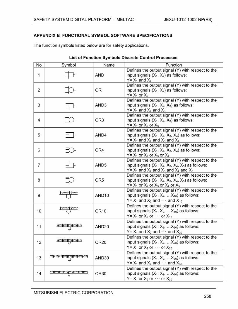
SAFETY SYSTEM DIGITAL PLATFORM - MELTAC - JEXU-1012-1002-NP(R8)
MITSUBISHI ELECTRIC CORPORATION
258
APPENDIX B FUNCTIONAL SYMBOL SOFTWARE SPECIFICATIONS The function symbols listed below are for safety applications.
List of Function Symbols Discrete Control Processes
No Symbol Name Function
1
AND Defines the output signal (Y) with respect to the input signals (X1, X2) as follows: Y= X1 and X2
2
OR Defines the output signal (Y) with respect to the input signals (X1, X2) as follows: Y= X1 or X2
3
AND3 Defines the output signal (Y) with respect to the input signals (X1, X2, X3) as follows: Y= X1 and X2 and X3
4
OR3 Defines the output signal (Y) with respect to the input signals (X1, X2, X3) as follows: Y= X1 or X2 or X3
5
AND4 Defines the output signal (Y) with respect to the input signals (X1, X2, X3, X4) as follows: Y= X1 and X2 and X3 and X4
6
OR4 Defines the output signal (Y) with respect to the input signals (X1, X2, X3, X4) as follows: Y= X1 or X2 or X3 or X4
7
AND5 Defines the output signal (Y) with respect to the input signals (X1, X2, X3, X4, X5) as follows: Y= X1 and X2 and X3 and X4 and X5
8
OR5 Defines the output signal (Y) with respect to the input signals (X1, X2, X3, X4, X5) as follows: Y= X1 or X2 or X3 or X4 or X5
9
AND10 Defines the output signal (Y) with respect to the input signals (X1, X2, …X10) as follows: Y= X1 and X2 and ・・・ and X10
10
OR10 Defines the output signal (Y) with respect to the input signals (X1, X2, …X10) as follows: Y= X1 or X2 or ・・・ or X10
11
AND20 Defines the output signal (Y) with respect to the input signals (X1, X2, …X20) as follows: Y= X1 and X2 and ・・・ and X20
12
OR20 Defines the output signal (Y) with respect to the input signals (X1, X2, …X20) as follows: Y= X1 or X2 or ・・・ or X20
13
AND30 Defines the output signal (Y) with respect to the input signals (X1, X2, …X30) as follows: Y= X1 and X2 and ・・・ and X30
14
OR30 Defines the output signal (Y) with respect to the input signals (X1, X2, …X10) as follows: Y= X1 or X2 or ・・・ or X30
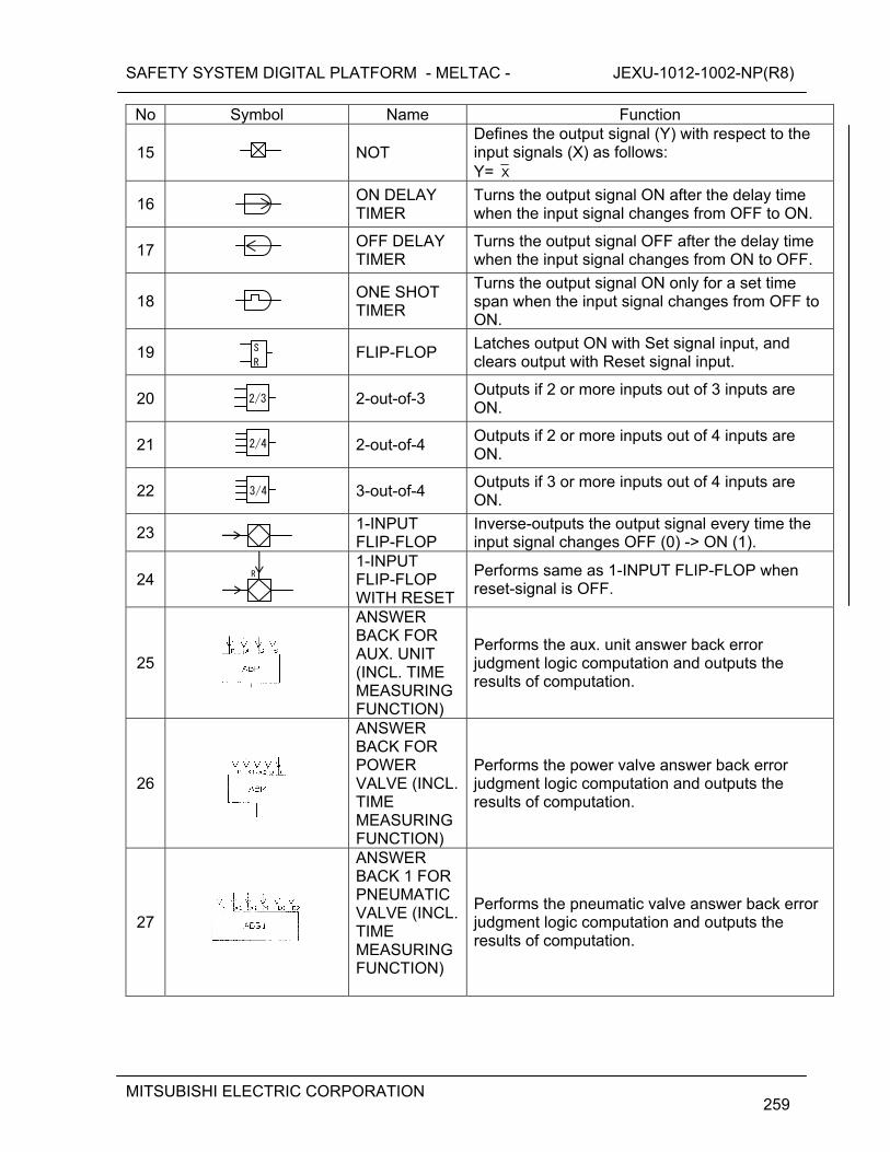
SAFETY SYSTEM DIGITAL PLATFORM - MELTAC - JEXU-1012-1002-NP(R8)
MITSUBISHI ELECTRIC CORPORATION
259
No Symbol Name Function
15
NOT Defines the output signal (Y) with respect to the input signals (X) as follows: Y= X
16 ON DELAY
TIMER Turns the output signal ON after the delay time when the input signal changes from OFF to ON.
17 OFF DELAY
TIMER Turns the output signal OFF after the delay time when the input signal changes from ON to OFF.
18
ONE SHOT TIMER
Turns the output signal ON only for a set time span when the input signal changes from OFF to ON.
19
FLIP-FLOP Latches output ON with Set signal input, and clears output with Reset signal input.
20
2-out-of-3 Outputs if 2 or more inputs out of 3 inputs are ON.
21
2-out-of-4 Outputs if 2 or more inputs out of 4 inputs are ON.
22
3-out-of-4 Outputs if 3 or more inputs out of 4 inputs are ON.
23 1-INPUT
FLIP-FLOP Inverse-outputs the output signal every time the input signal changes OFF (0) -> ON (1).
24 1-INPUT
FLIP-FLOP WITH RESET
Performs same as 1-INPUT FLIP-FLOP when reset-signal is OFF.
25
ANSWER BACK FOR AUX. UNIT (INCL. TIME MEASURING FUNCTION)
Performs the aux. unit answer back error judgment logic computation and outputs the results of computation.
26
ANSWER BACK FOR POWER VALVE (INCL. TIME MEASURING FUNCTION)
Performs the power valve answer back error judgment logic computation and outputs the results of computation.
27
ANSWER BACK 1 FOR PNEUMATIC VALVE (INCL. TIME MEASURING FUNCTION)
Performs the pneumatic valve answer back error judgment logic computation and outputs the results of computation.
S
R
2/3
2/4
3/4
R
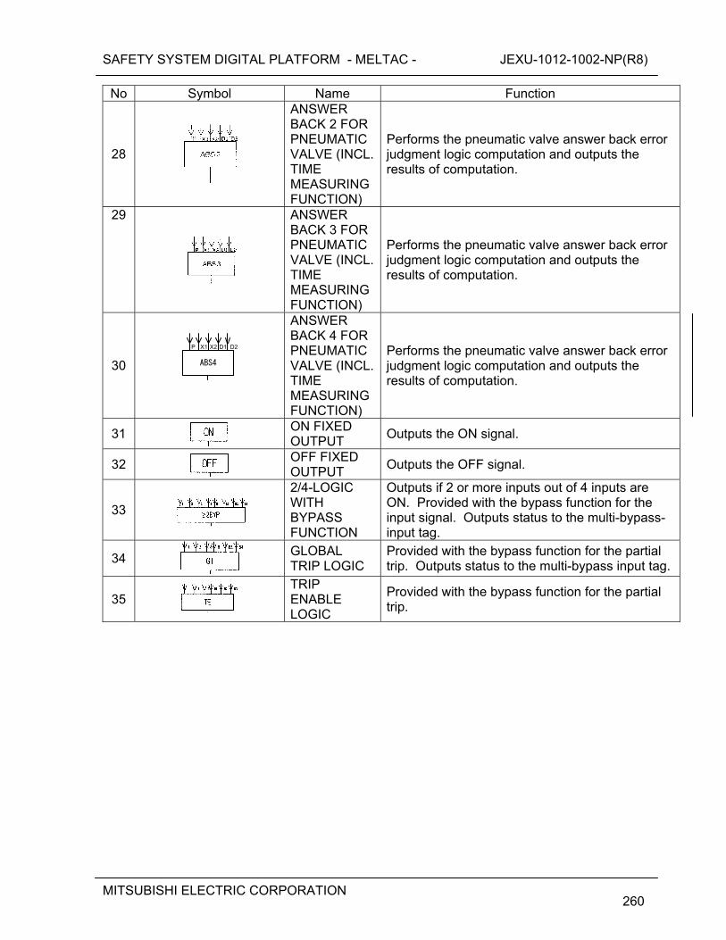
SAFETY SYSTEM DIGITAL PLATFORM - MELTAC - JEXU-1012-1002-NP(R8)
MITSUBISHI ELECTRIC CORPORATION
260
No Symbol Name Function
28
ANSWER BACK 2 FOR PNEUMATIC VALVE (INCL. TIME MEASURING FUNCTION)
Performs the pneumatic valve answer back error judgment logic computation and outputs the results of computation.
29
ANSWER BACK 3 FOR PNEUMATIC VALVE (INCL. TIME MEASURING FUNCTION)
Performs the pneumatic valve answer back error judgment logic computation and outputs the results of computation.
30
ANSWER BACK 4 FOR PNEUMATIC VALVE (INCL. TIME MEASURING FUNCTION)
Performs the pneumatic valve answer back error judgment logic computation and outputs the results of computation.
31
ON FIXED OUTPUT
Outputs the ON signal.
32
OFF FIXED OUTPUT
Outputs the OFF signal.
33
2/4-LOGIC WITH BYPASS FUNCTION
Outputs if 2 or more inputs out of 4 inputs are ON. Provided with the bypass function for the input signal. Outputs status to the multi-bypass-input tag.
34
GLOBAL TRIP LOGIC
Provided with the bypass function for the partial trip. Outputs status to the multi-bypass input tag.
35
TRIP ENABLE LOGIC
Provided with the bypass function for the partial trip.
ABS4
P X1 X2 D1 D2
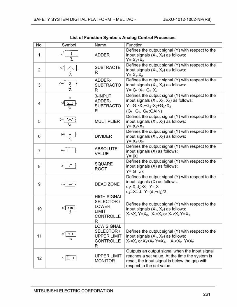
SAFETY SYSTEM DIGITAL PLATFORM - MELTAC - JEXU-1012-1002-NP(R8)
MITSUBISHI ELECTRIC CORPORATION
261
List of Function Symbols Analog Control Processes
No. Symbol Name Function
1
ADDER Defines the output signal (Y) with respect to the input signals (X1, X2) as follows: Y= X1+X2
2
SUBTRACTER
Defines the output signal (Y) with respect to the input signals (X1, X2) as follows: Y= X1-X2
3
ADDER- SUBTRACTOR
Defines the output signal (Y) with respect to the input signals (X1, X2) as follows: Y= G1・X1+G2・X2
4
3-INPUT ADDER- SUBTRACTOR
Defines the output signal (Y) with respect to the input signals (X1, X2, X3) as follows: Y= G1・X1+G2・X2+G3・X3 (G1,G2,G3 :GAIN)
5
MULTIPLIER Defines the output signal (Y) with respect to the input signals (X1, X2) as follows: Y= X1×X2
6
DIVIDER Defines the output signal (Y) with respect to the input signals (X1, X2) as follows: Y= X1÷X2
7
ABSOLUTE VALUE
Defines the output signal (Y) with respect to the input signals (X) as follows: Y= |X|
8
SQUARE ROOT
Defines the output signal (Y) with respect to the input signals (X) as follows: Y= G・ X
9
DEAD ZONE
Defines the output signal (Y) with respect to the input signals (X) as follows: d1<X,d2>X Y= X d2
X
d1 Y=(d1+d2)/2
10
HIGH SIGNAL SELECTOR / LOWER LIMIT CONTROLLER
Defines the output signal (Y) with respect to the input signals (X1, X2) as follows: X1<X2 Y=X2, X1=X2 or X1>X2 Y=X1
11
LOW SIGNAL SELECTOR / UPPER LIMIT CONTROLLER
Defines the output signal (Y) with respect to the input signals (X1, X2) as follows: X1=X2 or X1<X2 Y=X1, X1>X2 Y=X2
12
UPPER LIMIT MONITOR
Outputs an output signal when the input signal reaches a set value. At the time the system is reset, the input signal is below the gap with respect to the set value.
3
2 1
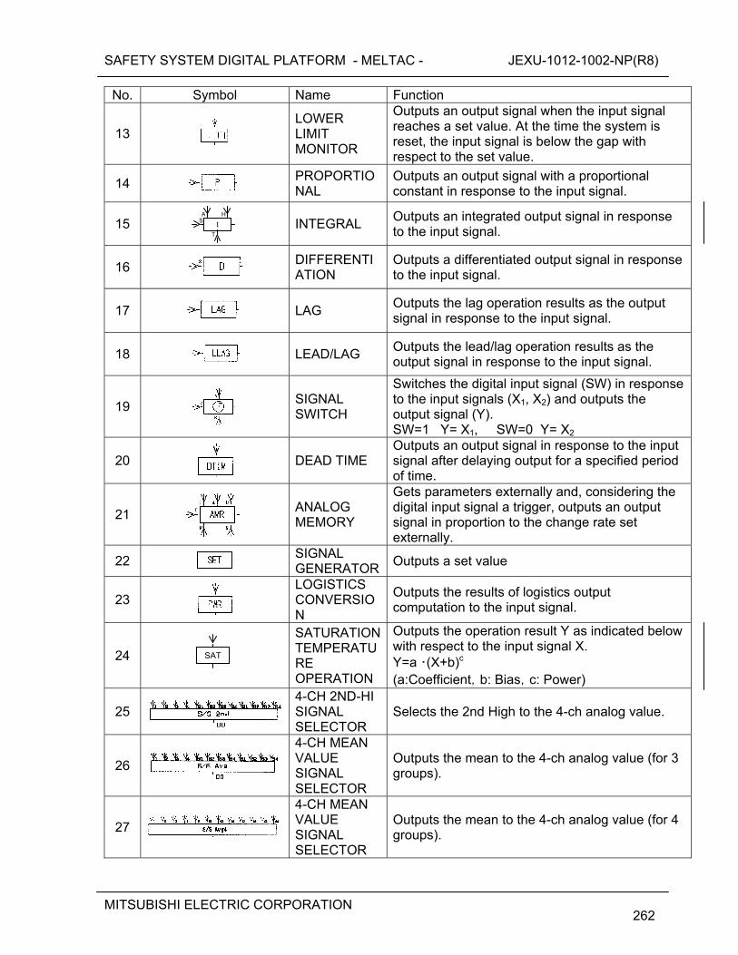
SAFETY SYSTEM DIGITAL PLATFORM - MELTAC - JEXU-1012-1002-NP(R8)
MITSUBISHI ELECTRIC CORPORATION
262
No. Symbol Name Function
13
LOWER LIMIT MONITOR
Outputs an output signal when the input signal reaches a set value. At the time the system is reset, the input signal is below the gap with respect to the set value.
14
PROPORTIONAL
Outputs an output signal with a proportional constant in response to the input signal.
15
INTEGRAL Outputs an integrated output signal in response to the input signal.
16
DIFFERENTIATION
Outputs a differentiated output signal in response to the input signal.
17
LAG Outputs the lag operation results as the output signal in response to the input signal.
18
LEAD/LAG Outputs the lead/lag operation results as the output signal in response to the input signal.
19
SIGNAL SWITCH
Switches the digital input signal (SW) in response to the input signals (X1, X2) and outputs the output signal (Y). SW=1 Y= X1, SW=0 Y= X2
20
DEAD TIME Outputs an output signal in response to the input signal after delaying output for a specified period of time.
21
ANALOG MEMORY
Gets parameters externally and, considering the digital input signal a trigger, outputs an output signal in proportion to the change rate set externally.
22
SIGNAL GENERATOR
Outputs a set value
23
LOGISTICS CONVERSION
Outputs the results of logistics output computation to the input signal.
24
SATURATION TEMPERATURE OPERATION
Outputs the operation result Y as indicated below with respect to the input signal X. Y=a ・(X+b)c (a:Coefficient,b: Bias,c: Power)
25
4-CH 2ND-HI SIGNAL SELECTOR
Selects the 2nd High to the 4-ch analog value.
26
4-CH MEAN VALUE SIGNAL SELECTOR
Outputs the mean to the 4-ch analog value (for 3 groups).
27
4-CH MEAN VALUE SIGNAL SELECTOR
Outputs the mean to the 4-ch analog value (for 4 groups).
I S
T
A H
SAT
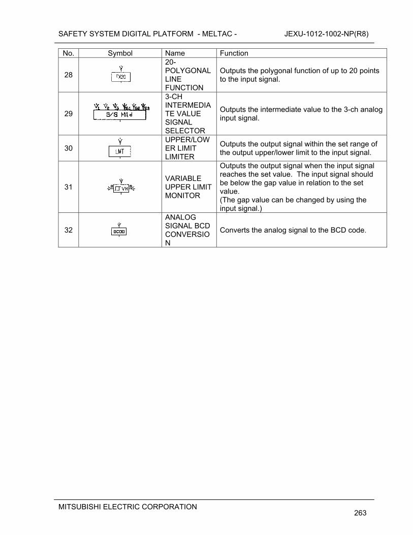
SAFETY SYSTEM DIGITAL PLATFORM - MELTAC - JEXU-1012-1002-NP(R8)
MITSUBISHI ELECTRIC CORPORATION
263
No. Symbol Name Function
28
20-POLYGONAL LINE FUNCTION
Outputs the polygonal function of up to 20 points to the input signal.
29
3-CH INTERMEDIATE VALUE SIGNAL SELECTOR
Outputs the intermediate value to the 3-ch analog input signal.
30
UPPER/LOWER LIMIT LIMITER
Outputs the output signal within the set range of the output upper/lower limit to the input signal.
31
VARIABLE UPPER LIMIT MONITOR
Outputs the output signal when the input signal reaches the set value. The input signal should be below the gap value in relation to the set value. (The gap value can be changed by using the input signal.)
32
ANALOG SIGNAL BCD CONVERSION
Converts the analog signal to the BCD code.
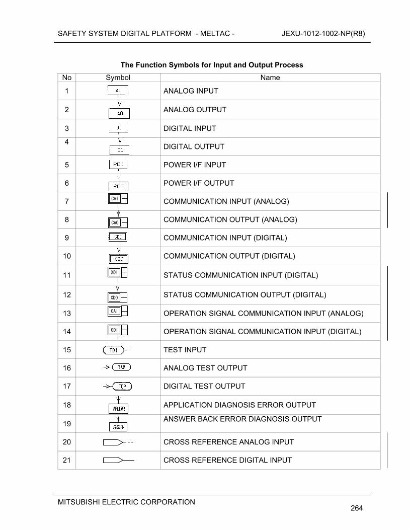
SAFETY SYSTEM DIGITAL PLATFORM - MELTAC - JEXU-1012-1002-NP(R8)
MITSUBISHI ELECTRIC CORPORATION
264
The Function Symbols for Input and Output Process
No Symbol Name
1
ANALOG INPUT
2
ANALOG OUTPUT
3
DIGITAL INPUT
4
DIGITAL OUTPUT
5
POWER I/F INPUT
6
POWER I/F OUTPUT
7
COMMUNICATION INPUT (ANALOG)
8
COMMUNICATION OUTPUT (ANALOG)
9
COMMUNICATION INPUT (DIGITAL)
10
COMMUNICATION OUTPUT (DIGITAL)
11
STATUS COMMUNICATION INPUT (DIGITAL)
12
STATUS COMMUNICATION OUTPUT (DIGITAL)
13
OPERATION SIGNAL COMMUNICATION INPUT (ANALOG)
14
OPERATION SIGNAL COMMUNICATION INPUT (DIGITAL)
15
TEST INPUT
16 ANALOG TEST OUTPUT
17
DIGITAL TEST OUTPUT
18
APPLICATION DIAGNOSIS ERROR OUTPUT
19
ANSWER BACK ERROR DIAGNOSIS OUTPUT
20
CROSS REFERENCE ANALOG INPUT
21
CROSS REFERENCE DIGITAL INPUT
CAI
CAO
XDI
XDO
OAI
ODI
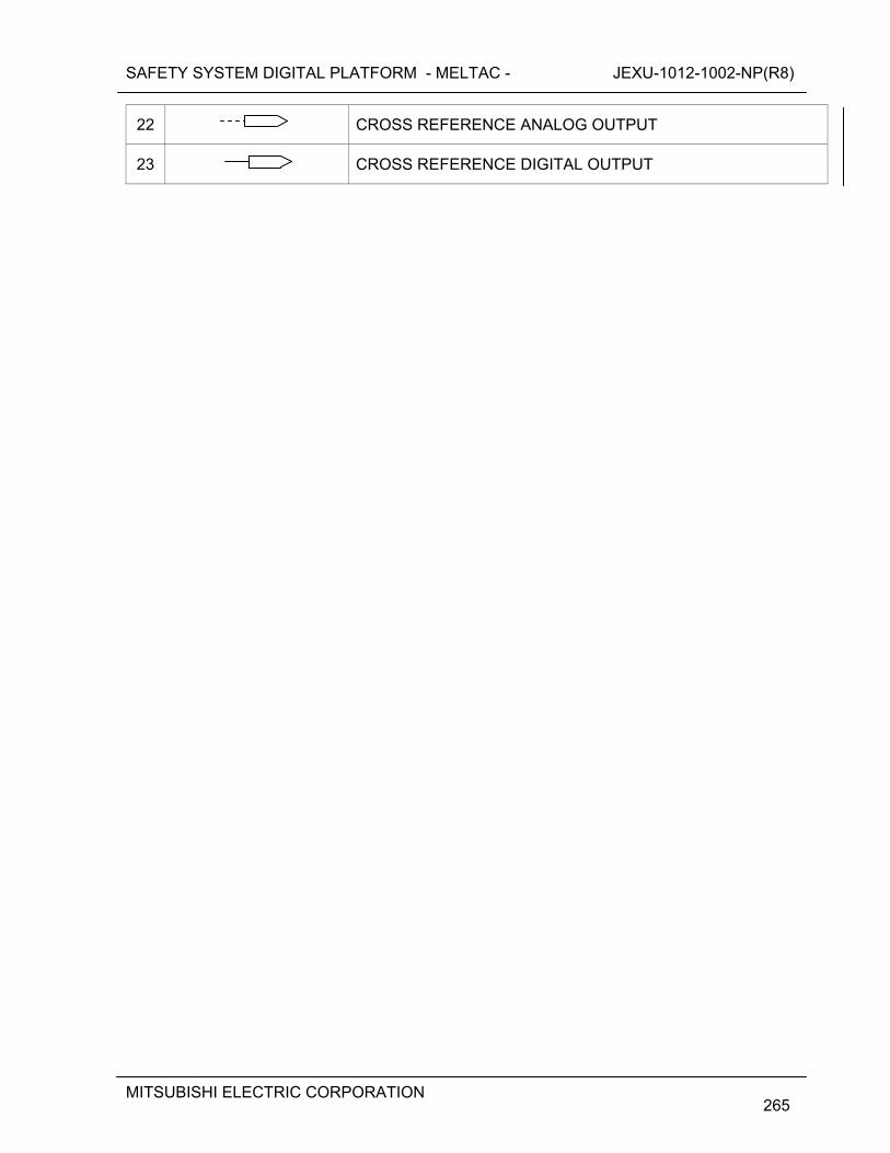
SAFETY SYSTEM DIGITAL PLATFORM - MELTAC - JEXU-1012-1002-NP(R8)
MITSUBISHI ELECTRIC CORPORATION
265
22
CROSS REFERENCE ANALOG OUTPUT
23
CROSS REFERENCE DIGITAL OUTPUT
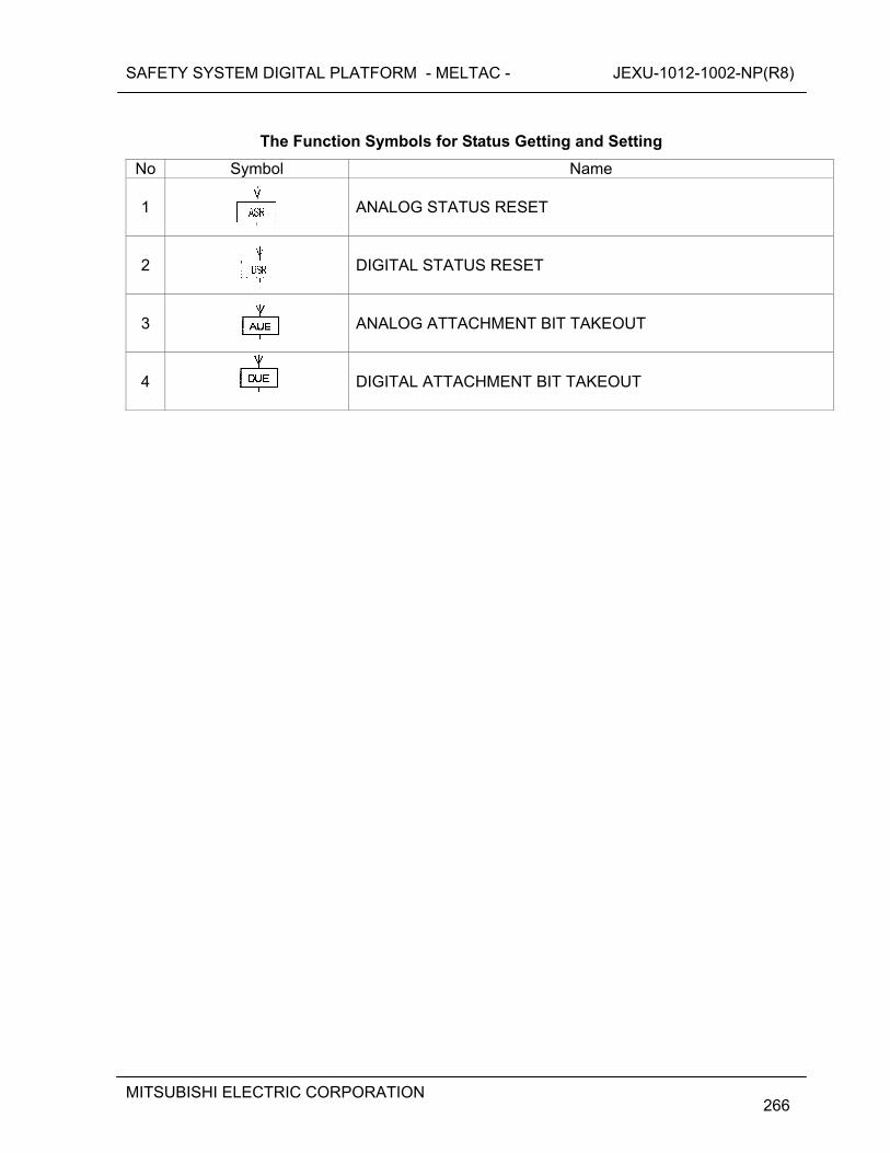
SAFETY SYSTEM DIGITAL PLATFORM - MELTAC - JEXU-1012-1002-NP(R8)
MITSUBISHI ELECTRIC CORPORATION
266
The Function Symbols for Status Getting and Setting
No Symbol Name
1
ANALOG STATUS RESET
2
DIGITAL STATUS RESET
3
ANALOG ATTACHMENT BIT TAKEOUT
4
DIGITAL ATTACHMENT BIT TAKEOUT
SAFETY SYSTEM DIGITAL PLATFORM - MELTAC - JEXU-1012-1002-NP(R8)
MITSUBISHI ELECTRIC CORPORATION
267
APPENDIX C CONFORMANCE TO BTP 7-14 The documents identified in the Table below are applicable to the generic MELTAC platform. Additional documents, applicable to plant specific applications, such as Factory Acceptance Test Procedures and Reports, are identified in application specific or project specific documentation. [
] (1) Software Life Cycle Process Planning

SAFETY SYSTEM DIGITAL PLATFORM - MELTAC - JEXU-1012-1002-NP(R8)
MITSUBISHI ELECTRIC CORPORATION
268
SAFETY SYSTEM DIGITAL PLATFORM - MELTAC - JEXU-1012-1002-NP(R8)
MITSUBISHI ELECTRIC CORPORATION
269

SAFETY SYSTEM DIGITAL PLATFORM - MELTAC - JEXU-1012-1002-NP(R8)
MITSUBISHI ELECTRIC CORPORATION
270
(2) Software Life Cycle Process Implementation
SAFETY SYSTEM DIGITAL PLATFORM - MELTAC - JEXU-1012-1002-NP(R8)
MITSUBISHI ELECTRIC CORPORATION
271
(3) Software Life Cycle Process Design Outputs
SAFETY SYSTEM DIGITAL PLATFORM - MELTAC - JEXU-1012-1002-NP(R8)
MITSUBISHI ELECTRIC CORPORATION
272
APPENDIX D CONFORMANCE MAP OF ISG-04 CHAPTER 1
Figure D-1 and Figure D-2 show how data communication complies with ISG-04 requirement. Figure D-1 is for the Control Network and Figure D-2 is for the Data Link.
SA
FE
TY
SY
ST
EM
DIG
ITA
L P
LAT
FO
RM
- M
ELT
AC
-
JE
XU
-101
2-10
02-N
P(R
8)
M
ITS
UB
ISH
I ELE
CT
RIC
CO
RP
OR
AT
ION
273
F
igu
re D
-1 C
on
form
ance
Map
of
ISG
-04
(Co
ntr
ol N
etw
ork
)
SA
FE
TY
SY
ST
EM
DIG
ITA
L P
LAT
FO
RM
- M
ELT
AC
-
JE
XU
-101
2-10
02-N
P(R
8)
M
ITS
UB
ISH
I ELE
CT
RIC
CO
RP
OR
AT
ION
274
Fig
ure
D-2
Co
nfo
rman
ce M
ap o
f IS
G-0
4 (D
ata
Lin
k)
SAFETY SYSTEM DIGITAL PLATFORM - MELTAC - JEXU-1012-1002-NP(R8)
MITSUBISHI ELECTRIC CORPORATION
275
APPENDIX E SOFTWARE CRITICAL FUNCTION ANALYSIS
Appendix E describes the results of a specific software critical function analysis activity for the MELTAC platform basic software as described in Section 6.1.12.
The description provided in APPENDIX E is the result of the analysis conducted for the developed MELTAC. If MELTAC is updated, an analysis will be conducted in accordance with MELTAC Platform Basic Software Program Manual (JEXU-1012-1132).
The specific activity addressed in this software critical function analysis is identification and analysis of potential hazards that may adversely affect critical platform functions. This analysis assesses the effectiveness of mitigating platform level design features which ensure the hazards are correctly detected and the platform responds as specified.
The software critical function analysis activities conducted for the MELTAC platform basic software are supplemented by the software critical function analysis activities conducted for critical application level functions, as defined by the US-APWR Software Program Manual (MUAP-07017).
SAFETY SYSTEM DIGITAL PLATFORM - MELTAC - JEXU-1012-1002-NP(R8)
MITSUBISHI ELECTRIC CORPORATION
276
E.1 SCOPE E.1.1 Analysis Target
The following table identifies the major hazards for the MELTAC basic software, that have the possibility to interfere with correct system operation.
Table E.1-1 Potential Hazards
SAFETY SYSTEM DIGITAL PLATFORM - MELTAC - JEXU-1012-1002-NP(R8)
MITSUBISHI ELECTRIC CORPORATION
277
E.1.2 Analysis Criteria
The potential hazards noted in Table E.1-2 will be checked against the following criteria.
Table E.1-2 Acceptance Criteria
SAFETY SYSTEM DIGITAL PLATFORM - MELTAC - JEXU-1012-1002-NP(R8)
MITSUBISHI ELECTRIC CORPORATION
278
E.2 SOFTWARE CRITICAL FUNCTION ANALYSIS RESULT It was analyzed if faults can be detected at the architecture level. If detection was done by software, its implementation was confirmed through verification of
specification document and source code. The Analysis column in the tables below describes the method of tolerating the hazard, and the specific section(s) of the document(s) which identify this tolerance method.
Compliance to some requirements is determined through the application system configuration or application software. For these requirements, the analysis identifies example(s) of the compliance method(s), without identifying specific documentation. The documentation reference is application specific.
E.2.1 Detectability of Input, Operation, and Output hazards
The results of analyzing the detectability of input, operation, and output hazards are as
follows. For input from the network, refer to “MELTAC Platform ISG-04 Conformance Analysis”
(JEXU-1015-1009).
SAFETY SYSTEM DIGITAL PLATFORM - MELTAC - JEXU-1012-1002-NP(R8)
MITSUBISHI ELECTRIC CORPORATION
279
SAFETY SYSTEM DIGITAL PLATFORM - MELTAC - JEXU-1012-1002-NP(R8)
MITSUBISHI ELECTRIC CORPORATION
280
E.2.2 Analysis of Self-Diagnosis Functions The results of analyzing the self-diagnosis functions are as follows.
E.2.2.1 CPU Module
SAFETY SYSTEM DIGITAL PLATFORM - MELTAC - JEXU-1012-1002-NP(R8)
MITSUBISHI ELECTRIC CORPORATION
281

SAFETY SYSTEM DIGITAL PLATFORM - MELTAC - JEXU-1012-1002-NP(R8)
MITSUBISHI ELECTRIC CORPORATION
282

SAFETY SYSTEM DIGITAL PLATFORM - MELTAC - JEXU-1012-1002-NP(R8)
MITSUBISHI ELECTRIC CORPORATION
283

SAFETY SYSTEM DIGITAL PLATFORM - MELTAC - JEXU-1012-1002-NP(R8)
MITSUBISHI ELECTRIC CORPORATION
284
SAFETY SYSTEM DIGITAL PLATFORM - MELTAC - JEXU-1012-1002-NP(R8)
MITSUBISHI ELECTRIC CORPORATION
285
E.2.2.2 System Management Module (SMM)

SAFETY SYSTEM DIGITAL PLATFORM - MELTAC - JEXU-1012-1002-NP(R8)
MITSUBISHI ELECTRIC CORPORATION
286

SAFETY SYSTEM DIGITAL PLATFORM - MELTAC - JEXU-1012-1002-NP(R8)
MITSUBISHI ELECTRIC CORPORATION
287
SAFETY SYSTEM DIGITAL PLATFORM - MELTAC - JEXU-1012-1002-NP(R8)
MITSUBISHI ELECTRIC CORPORATION
288
E.2.2.3 Bus Master Module

SAFETY SYSTEM DIGITAL PLATFORM - MELTAC - JEXU-1012-1002-NP(R8)
MITSUBISHI ELECTRIC CORPORATION
289

SAFETY SYSTEM DIGITAL PLATFORM - MELTAC - JEXU-1012-1002-NP(R8)
MITSUBISHI ELECTRIC CORPORATION
290
SAFETY SYSTEM DIGITAL PLATFORM - MELTAC - JEXU-1012-1002-NP(R8)
MITSUBISHI ELECTRIC CORPORATION
291
E.2.2.4 Control Network I/F Module

SAFETY SYSTEM DIGITAL PLATFORM - MELTAC - JEXU-1012-1002-NP(R8)
MITSUBISHI ELECTRIC CORPORATION
292

SAFETY SYSTEM DIGITAL PLATFORM - MELTAC - JEXU-1012-1002-NP(R8)
MITSUBISHI ELECTRIC CORPORATION
293

SAFETY SYSTEM DIGITAL PLATFORM - MELTAC - JEXU-1012-1002-NP(R8)
MITSUBISHI ELECTRIC CORPORATION
294

SAFETY SYSTEM DIGITAL PLATFORM - MELTAC - JEXU-1012-1002-NP(R8)
MITSUBISHI ELECTRIC CORPORATION
295
SAFETY SYSTEM DIGITAL PLATFORM - MELTAC - JEXU-1012-1002-NP(R8)
MITSUBISHI ELECTRIC CORPORATION
296
E.2.2.5 FMU Module

SAFETY SYSTEM DIGITAL PLATFORM - MELTAC - JEXU-1012-1002-NP(R8)
MITSUBISHI ELECTRIC CORPORATION
297
SAFETY SYSTEM DIGITAL PLATFORM - MELTAC - JEXU-1012-1002-NP(R8)
MITSUBISHI ELECTRIC CORPORATION
298
E.2.2.6 Touch Panel Interface Module

SAFETY SYSTEM DIGITAL PLATFORM - MELTAC - JEXU-1012-1002-NP(R8)
MITSUBISHI ELECTRIC CORPORATION
299
SAFETY SYSTEM DIGITAL PLATFORM - MELTAC - JEXU-1012-1002-NP(R8)
MITSUBISHI ELECTRIC CORPORATION
300
E.2.2.7 Safety VDU Panel

SAFETY SYSTEM DIGITAL PLATFORM - MELTAC - JEXU-1012-1002-NP(R8)
MITSUBISHI ELECTRIC CORPORATION
301
E.2.2.8 Analog Input Module

SAFETY SYSTEM DIGITAL PLATFORM - MELTAC - JEXU-1012-1002-NP(R8)
MITSUBISHI ELECTRIC CORPORATION
302
SAFETY SYSTEM DIGITAL PLATFORM - MELTAC - JEXU-1012-1002-NP(R8)
MITSUBISHI ELECTRIC CORPORATION
303
E.2.2.9 Analog Output Module

SAFETY SYSTEM DIGITAL PLATFORM - MELTAC - JEXU-1012-1002-NP(R8)
MITSUBISHI ELECTRIC CORPORATION
304
SAFETY SYSTEM DIGITAL PLATFORM - MELTAC - JEXU-1012-1002-NP(R8)
MITSUBISHI ELECTRIC CORPORATION
305
E.2.2.10 Digital Input Module

SAFETY SYSTEM DIGITAL PLATFORM - MELTAC - JEXU-1012-1002-NP(R8)
MITSUBISHI ELECTRIC CORPORATION
306
E.2.2.11 Digital Output Module
SAFETY SYSTEM DIGITAL PLATFORM - MELTAC - JEXU-1012-1002-NP(R8)
MITSUBISHI ELECTRIC CORPORATION
307
E.2.2.12 PIF Module

SAFETY SYSTEM DIGITAL PLATFORM - MELTAC - JEXU-1012-1002-NP(R8)
MITSUBISHI ELECTRIC CORPORATION
308

SAFETY SYSTEM DIGITAL PLATFORM - MELTAC - JEXU-1012-1002-NP(R8)
MITSUBISHI ELECTRIC CORPORATION
309
E.2.2.13 Repeater Module

SAFETY SYSTEM DIGITAL PLATFORM - MELTAC - JEXU-1012-1002-NP(R8)
MITSUBISHI ELECTRIC CORPORATION
310
E.2.2.14 Power Supply Module

SAFETY SYSTEM DIGITAL PLATFORM - MELTAC - JEXU-1012-1002-NP(R8)
MITSUBISHI ELECTRIC CORPORATION
311
E.2.2.15 Controller Cabinet
SAFETY SYSTEM DIGITAL PLATFORM - MELTAC - JEXU-1012-1002-NP(R8)
MITSUBISHI ELECTRIC CORPORATION
312
REFERENCED DOCUMENTATION The following table is a list of specification documentation referenced in this analysis.
SAFETY SYSTEM DIGITAL PLATFORM - MELTAC - JEXU-1012-1002-NP(R8)
MITSUBISHI ELECTRIC CORPORATION
313
APPENDIX F DEFINITION Alarm The minor abnormality with which the Subsystem can continue its functions is
categorized as the Alarm. This includes the error of the Controller Cabinet. When the Subsystem detects this type of error, it does not change its mode and only warns of the alarm.
Application Software The application software reflects the plant specific functionality of the US-APWR
I&C systems that apply MELTAC technology. It is documented and generated by the MELENS Engineering Tool. The platform system software uses this configuration data to carry out the application specific functionality of the US-APWR I&C systems.
Basic Software The MELTAC platform basic software is low-level software that operates the
MELTAC controllers. This software consists of initialization code, device drivers, communication layers, function blocks, diagnostics, etc. for the MELTAC platform including firmware and FPGA.
Bus Master Module The Bus Master Module has 4 communication interface channels to use for
communication with I/O modules or Data Link communication.
Control Mode A state in which the Subsystem performs input, operation, output processing, and
self-diagnosis.
Control Network
The Control Network is a MELTAC dedicated ring topology network and communicates plant process data and control signal data with a deterministic periodic cycle.
Control Network I/F Module The Control Network I/F Module connects the Controller to the Control Network.
CPU Chassis The CPU Chassis can accommodate various modules such as the Power Supply
Module, CPU Module, Control Network I/F Module, System Management Module and Bus Master Module. There are three types of CPU Chassis, Mirror-split type, Slide-split type, and Non-split type.
CPU Fan The CPU Fan is installed on top of the CPU Chassis to cool the modules within the
CPU Chassis.
CPU Module The CPU Module utilizes a 32-bit microprocessor and performs internal operations
and data transmission with other modules (i.e. Bus Master Module, Control Network I/F Module and System Management Module). This module utilizes UV-ROM for storing the basic software and F-ROM for storing the application software.
SAFETY SYSTEM DIGITAL PLATFORM - MELTAC - JEXU-1012-1002-NP(R8)
MITSUBISHI ELECTRIC CORPORATION
314
Data Link The Data Link communication is used to transmit process signals between
controllers of different safety divisions. This communication is unidirectional.
Dedicated Re-programming Chassis The F-ROM can be updated only when the CPU Module is placed in this chassis
after removing it from the on-line controller chassis
Distribution Module The signal input into the I/O module frame is distributed by the Distribution Module
on the rear side of the module frame, and the distributed signals input into the duplex I/O module. Similarly, the output signal is output through the distribution module.
Door Fan Unit The Door Fan Unit is installed at the top rear of the cabinet to cool internal cabinet
components.
EEPROM Electrically Erasable Programmable Read Only Memory.
EEPROM can be erased and reprogrammed repeatedly through the application of higher than normal electrical voltage.
Electrical/Optical (E/O) Converter Module The Electrical/Optical (E/O) Converter Module for Data Link communication,
converts electrical signals to optical signals or optical signals to electrical signals.
Electrical/Optical Converter Chassis The Electrical/Optical(O/E) Converter Chassis can accommodate up to 14 O/E
converter modules per chassis.
Failure
The fatal abnormality by which the Subsystem cannot continue its functions is categorized as the Failure. When the Subsystem detects this type of error, it transits to the Failure mode. In the Failure mode, the processing of input/output and operation are stopped, although the
Failure Mode The Subsystem initializes to the Failure Mode after initial power activation. The
Subsystem also shifts to this mode automatically after it detects its own failure or there is a loss of power greater than 20msec. A Subsystem shifts from the Failure Mode to the Control Mode only by pushing the reset button on the Status Display module.
FPGA Field Programmable Gate Array.
FPGA has many internal logical blocks consisting of logic gates and arithmetic circuits. Internal logical blocks are located on a matrix. Required circuit configuration are implemented by connecting these internal logical blocks.
Frame Memory Unit (FMU) Module. The FMU Module provides the analog RGB signal for the graphic images to the
safety VDU panel. And this module also provides the touch panel interface signal from the safety VDU panel to the safety VDU processor by means of RS-232C data link.
SAFETY SYSTEM DIGITAL PLATFORM - MELTAC - JEXU-1012-1002-NP(R8)
MITSUBISHI ELECTRIC CORPORATION
315
F-ROM
Flash Read Only Memory. F-ROM is also called flash memory. One of the nonvolatile semiconductor memories in which data do not disappear even after a device is turned off.
I/O Alarm
The abnormality of I/O is categorized as the I/O Alarm. When the Subsystem detects this type of error, it does not change its mode and only warns of the alarm. In case of Redundant Standby
I/O Bus
A communication line between the Bus Master Module and the Input/Output Chassis. The I/O Bus is used for transmission of data, such as process inputs from the I/O module to the CPU Module and output commands from the CPU Module to the I/O module.
Input/Output Chassis
The I/O Chassis can accommodate up to 16 I/O modules per chassis.
Input/Output(I/O) Modules
The I/O module provides process input/output function and signal conditioner function, including signal conversion and noise reduction.
Isolation Module
Isolation Module provides electrical isolation between safety systems and non-safety systems.
Maintenance Network
The Maintenance Network is used to communicate between the controllers / safety VDUs and the MELTAC engineering tools to download new application software to the controllers / safety VDUs, or to read/write inside memory of the controller / safety VDUs.
MELENS
MELTAC Engineering Station. MELENS is a product name of the Engineering Tool. See the definition of "Engineering Tool".
MELTAC Controller
Mitsubishi Electric Total Advanced Controller. A safety system digital platform for nuclear power plants
MELTAC engineering tool
The MELTAC engineering tool is the tool that generates applications operate on the MELTAC, downloads generated applications to controllers, and displays failure and status information of the MELTAC (see 4.1.4.1 for details). This tool consists of (Windows-based) non-safety PC and utility software called "MELENS.
SAFETY SYSTEM DIGITAL PLATFORM - MELTAC - JEXU-1012-1002-NP(R8)
MITSUBISHI ELECTRIC CORPORATION
316
Optical Switch
The Optical Switch bypasses the Control Network communication line in the Control Network I/F Module during controller maintenance.
POL
Problem Oriented Language. This is the control language used in the MELCO's instrumentation controllers for nuclear power plants.
Power Interface Module
The Power InterFace (PIF) Module receives output commands as a result of Subsystem operation, and controls the power that drives the switchgears, solenoid valves, etc. for plant components.
Power Supply Fan Unit
The Power Supply Fan Units are installed at the bottom and the midsection on both the left and right-hand sides of the cabinet to cool the power supplies.
Power Supply Module
The Power Supply Modules convert the AC power supplied to the Chassis from two independent sources to DC power voltages suitable for the individual modules and units. Redundant Power Supply Modules are provided for CPU Chassis, I/O modules, Isolation Modules, Power Interface Modules, E/O Converter Modules and fan units.
Redundant Parallel Controller
In the "Redundant Parallel" configuration, the Controller includes two Subsystems. Each Subsystem operates in Control Mode. This configuration does not require reliance on the self-diagnosis function of the CPU part or the subsystem switching operation and therefore ensures the highest reliability of a safety system.
Redundant Standby Controller
In the "Redundant Standby" configuration, the Controller includes two Subsystems. One Subsystem operates in Control Mode while the other Subsystem operates in Standby Mode. This configuration allows a system to maintain high reliability even when any error is detected in the Subsystem in Control Mode by the self-diagnosis function, with a backup of the Subsystem in Standby Mode (i.e., status switching when the Control Subsystem fails).
Repeater Modules
The Repeater Modules shape and amplify data communication signals between I/O modules and Bus Master Module. This module is used in a I/O Chassis.
Safety VDU Panel
The safety VDU panel is an HSI device which provides a color graphic display with an integral touch screen.
Safety VDU Processor
The safety VDU processor transfers operation signals received from the VDU panel to safety systems and displays information of each system on the VDU panel.
SAFETY SYSTEM DIGITAL PLATFORM - MELTAC - JEXU-1012-1002-NP(R8)
MITSUBISHI ELECTRIC CORPORATION
317
Self-Diagnosis
The integrity of digital I&C components is continuously checked by their self-diagnostic features. These self-diagnostic features result in early detection of failures.
Single Controller
In the "Single" configuration, the Controller includes one Subsystem. The Subsystem operates in Control Mode. This configuration can be applied when a system is multiplexed.
Standby Mode
In this mode the Subsystem tracks the data from the subsystem in the Control Mode so it can automatically transition into the Control Mode if the other Subsystem transitions to the Failure Mode. When the Subsystem detects its own failure (through self-diagnostics), it automatically changes from the Standby Mode to the Failure Mode.
Status Display & Switch Module
The Status Display & Switch Module displays the mode and alarms of the Subsystems and provides the manual mode change over switch. This module is used in a CPU Chassis configured for a Redundant Standby Controller.
Status Display Module
The Status Display Module displays the mode and alarms of the single Subsystems. This module is used in a CPU Chassis configured for a Redundant Parallel Controller or Single Controller.
System Management Module
The System Management Module monitors the status of the CPU Module and executes auxiliary controller functions that are not directly related to the CPU Module such as Ethernet I/F for communicating with the Engineering Tool.
US Conformance Program (UCP)
US Conformance Program (UCP) is the combination of the corrective actions taken to compensate for differences between the MELCO's original QAP and US requirements, and the assessment of the developed software by the independent V&V Team.
UV-ROM
Ultra-Violet erasable programmable Read Only Memory. It is a programmable ROM, where data can be erased by ultraviolet light.
V&V Verification and Validation.
The process of determining 1) whether the requirements for a system or component are complete and correct, 2) whether the products of each development phase fulfill the requirements or conditions imposed by the previous phase, and 3) whether the final system or component complies with specified requirements.