Safety Standards and Collaborative Robots - robotics.org · • The speed of the robot moving...
32
Safety Standards and Collaborative Robots Pat Davison Robotic Industries Association
Transcript of Safety Standards and Collaborative Robots - robotics.org · • The speed of the robot moving...
Safety Standards and Collaborative Robots
Pat Davison Robotic Industries Association

Topics • What is it? • How did we get here? • What has already been done? • What still needs doing?

Standards • ISO 10218-1:2006 (updated 2011) and
ISO 10218-2:2011 are the industrial robot standards that initially covered collaborative applications – Part 1: Robot only (manipulator and controller)
– Part 2: Robot system/cell and application
• ISO TS 15066 is a Technical Specification on collaborative robots that should be available in 2015
• ANSI/RIA R15.06-2012 is an adoption of ISO 10218-1:2011 & ISO 10218-2:2011

Vocabulary lesson
• A collaborative robot is a robot that can be used in a collaborative operation –Collaborative operation (Part 1, 3.4) – state in
which purposely designed robots work in direct cooperation with a human within a defined workspace
*emphasis added

What Is A Collaborative Robot? • …within a collaborative workspace
–Collaborative workspace (Part 1, 3.5) – workspace within the safeguarded space where the robot and human can perform tasks simultaneously during production operation

What Is A Collaborative Robot? So really, a collaborative robot is defined by… • The task the robot is
performing; and • The space in which the
task is being performed, …and not the robot itself!

How Did We Get Here?
Google image search August 20, 2014

Risk
Risk = Likelihood X Consequence

Risk
Hazard Exposure
Vulnerability
Risk
Model proposed by WHO to examine health risks from natural disasters

Traditional Industrial Robot Risk Reduction
In production operation or automatic mode, operators are prevented from accessing the machine with
safeguarding devices.

Accessing the machine requires: • removing the safeguards, and • limiting, controlling or eliminating the machine’s energy.
Traditional Industrial Robot Risk Reduction

An Alternative Risk Model
Risk
Hazard Exposure
Vulnerability
WHO Model applied to industrial robotics applications

Hierarchy of Risk Reduction Elimination
Substitution
Safeguarding
Awareness Means
Admin Controls
PPE

Hierarchy of Risk Reduction The EU Machinery Directive, U.S. OSHA (29 CFR 1910) and other regulations require machine manufacturers to provide guarding to protect operators and employees from hazards.
Consensus standards (ISO, ANSI, CSA) provide guidance for the safe integration and application of machinery, but presume safeguarding is necessary to reduce risk.
Awareness means, administrative controls and PPE are an effective means of reducing residual risk AFTER hazards are reduced through engineered means.

Hierarchy of Risk Reduction It is assumed that the machine poses one or more hazards that require risk reduction measures. What if this isn’t true?
It is assumed that fixed and interlocked guards are necessary risk reduction measures. What if fixed guards are not necessary?
What if awareness means, administrative controls and PPE alone are an effective means of addressing low-risk machinery applications?
Assumptions associated with

Hierarchy of Risk Reduction Specially-designed machines can be used for pre-determined collaborative tasks involving direct operator contact when all required protective measures are active and all relevant risks have been acceptably reduced.
Exposure reduction relies on active machine protective measures. Safeguarding shall prevent operators from advancing beyond the safeguarded space, and cause hazards to cease if unacceptable conditions are detected.
Awareness means, administrative controls and PPE are an effective means of reducing risk AFTER machine hazards are reduced through engineered means.
Collaborative robot application
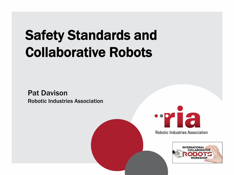
The Standard… Collaborative robot operations:
• Part 1, 5.10 – Information for robot manufacturer
• Part 2, 5.11 – Information for robot
integrator
• Part 2, Annex E and Annex G have information on conceptual applications and verification of safety requirements
Approximately 8 pages of the 152-page standard is specific to
collaborative robot operations

The Standard… Part 1, 5.10 Collaborative operation requirements – 5.10.1 General – Robots designed for collaborative operation shall provide a visual indication when the robot is in collaborative operation and comply with one or more of the following: • 5.10.2 Safety-rated monitored stop
(IEC 60204-1 category 2) • 5.10.3 Hand guiding (requires emergency stop and
enabling device) • 5.10.4 Speed and separation monitoring • 5.10.5 Power and force limiting by inherent design or
control

Safety-Rated Monitored Stop What the collaborative robot does in the presence of an operator or obstruction • Stop-motion condition ensured • Drive power remains on • Motion resumes after obstruction clears • Robot motion resumes without additional action • Protective stop delivered if stop condition is violated Applications • Direct part loading or unloading • Work-in-process inspections • Standstill function in other collaborative operations

Hand Guiding Where an operator leads robot movement through direct interface • Robot stops when operator arrives
(Safety-rated monitored stop)
• Operator grasps enabling device, activating motion • Robot motion responds to operator commands • Non-collaborative operation resumes when operator
leaves collaborative workspace Applications • Robotic lift assist • Highly variable applications • Limited or small-batch productions
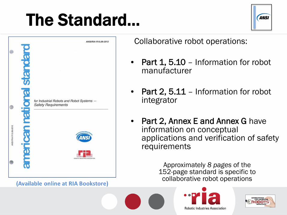
Speed & Separation Monitoring Where the robot speed reduces when an obstruction is detected Separation distances are monitored (scanners, vision systems, proximity sensors)
• Robot speed directly correlates to separation distance—zones dictate allowable speed
• Stop condition given if direct contact proximity is attained (Safety-rated monitored stop)
Applications • Simultaneous tasks • Direct operator interface
Safety-Rated Monitored Stop
Slow Speed
Medium Speed
Protective Stop

Safe separation distance is a function of: • The speed of the person moving toward the robot • The speed of the robot moving toward the person • The reaction time of the robot system to detect an
undesirable condition and initiate a stop • The intrusion distance that a part of the body can move past
the safeguard toward the hazard zone prior to actuation of the safeguard
• Position uncertainty for both the robot and operator A proposed model includes calculations that represent: 1. The change in separation distance due to the person’s
motion 2. The rate of change in separation distance due to the robot’s
motion up to the robot requesting a stop and braking. 3. The change in separation distance while the robot is
reacting and stopping.
Separation Distance
Image courtesy: Carnegie Mellon University
( ) RS
TTt
Tt R
Tt
t R
TTt
t Hcurrent ZZCdKdKdKtS BR
R
RBR +++++≥ ∫∫∫++=
+=
+=
=
++=
=
τ
τ
τ
τ
τ
τττττττ )()()(
1 2 3
Intrusion Distance

Power And Force Limiting Where incidental contact initiated by robot are limited in energy to not cause operator harm • Forces robot can exert are limited • Robot system design eliminates pinch points,
sharp edges, etc. • Robot complies and reacts when contact is made Applications • Small or highly variable applications • Conditions requiring frequent operator presence • Machine tending • Loading/unloading

Power And Force Limits? 80 watt/150 Newton P&F limits were in ISO 10218-1:2006 but were removed in ISO 10218-1:2011.
33.72 lb.
1 𝑊 = 1 𝑁𝑚𝑠
= 1𝑘𝑘 𝑚2
𝑠3
𝐹 = 𝑚𝑚
Does applied power or
force result in clamping?
Watts applied to mechanical power, not motor ratings
Force applied where? Could be hazardous, depending on where on the body the force was applied

Risk Assessment Part 2 requires a risk assessment for collaborative applications to evaluate task/hazard combinations and set appropriate limits • Means of anticipating tasks and hazards with
the goal of applying suitable risk reduction measures
• Uses an iterative process as a means to determine that risk reduction measures applied can achieve their desired effect
• Avoids “one size fits all” prescriptive measures, which can either be too restrictive or can require defeating safeguards in order to accomplish certain tasks
Diagram: RIA TR R15.306

Risk Assessment
• Initial risk of collaborative task/hazard pairs must be sufficiently low as a condition for risk reduction without guards.
• Elimination, substitution or guarding are required for task/hazard pairs that exhibit higher initial risks.
• Guarding may also be necessary to address non-collaborative tasks using the same equipment.
Tables: RIA TR R15.306 ANSI/B11.0

TS 15066: P&F Limiting Guidance Example
Power and force limits can be affected or modified by: • Eliminating pinch points • Reducing robot velocity, thereby
reducing transfer energy – E = ½mv2
• Reducing robot inertia or mass • Modifying robot posture, such that possible
exposure surface area is increased • Avoiding sensitive body areas
(i.e. head and neck) The application, not the robot, is key!

TS 15066: Onset Of Pain Study • TS 15066 will include guidance for
power and force limits based on a study examining power and force conditions and the onset of pain in 29 body regions.
• The study is being conducted at the University of Mainz in Germany
No pain/injury
Slight injury
Moderate injury
Serious injury
Pain onset
Death
Several data sources
Few data sources
Appl
ied
forc
e or
ene
rgy
See: http://www.dguv.de/ifa/Fachinfos/Kollaborierende-Roboter/index-2.jsp Search: “Mainz collaborative robot”
Collaborative robot applications

ISO TS 15066 The pain threshold map can be used to set power and force limits for P&F limiting robot applications, based on anticipated body contact location.
Energy transfer models will calculate maximum allowable robot velocity for given contact scenario.
Images: www.dguv.de

Summary • What is it?
– Collaborative robotics is a new robotic application allowing direct robot and operator interface without traditional safeguarding under specific conditions
• How did we get here? – Improvements in controls and machine technology
created opportunities to create machines that could safely operate without external safeguards
– Standards activities, including adoption of risk assessments and controls systems validation are identifying conditions where collaborative applications can be performed safely

Summary • What has already been done?
– International ISO and ANSI robot safety standards have identified specific applications and criteria where collaborative operations can occur
• What still needs doing? – ISO TS 15066 will provide additional guidance on the
safe implementation of each collaborative robot operation
– Regulatory acceptance of robots not utilizing traditional safeguards has not been determined

Thank You
Pat Davison Director, Standards Development Robotic Industries Association 900 Victors Way #140 Ann Arbor, MI 48108 Phone: 734-929-3269 [email protected] www.robotics.org