Safety Products - IDEC · Safety Products HS5E Series USA: (800) 262-IDEC or (408) 747-0550,...
11
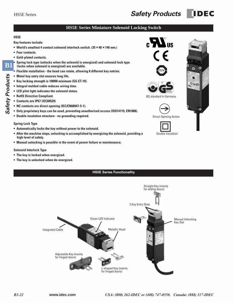
HS5E Series Safety Products B1-22 www.idec.com USA: (800) 262-IDEC or (408) 747-0550, Canada: (888) 317-IDEC B1 Safety Products HS5E Key features include: • World’s smallest 4 contact solenoid interlock switch. (35 × 40 × 146 mm.) • Four contacts. • Gold-plated contacts. • Spring lock type (unlocks when the solenoid is energized) and solenoid lock type (locks when solenoid is energized) are available. • Flexible installation - the head can rotate, allowing 8 different key entries. • Metal key entry slot ensures long life. • Key locking strength is 1000N minimum (GS-ET-19). • Integral molded cable reduces wiring time. • LED pilot light indicates the solenoid status. • RoHS Directive Compliant. • Contacts are IP67 (IEC60529) • NC contacts are direct opening (IEC/EN60947-5-1). • Only proprietary keys can be used, preventing unauthorized access (ISO14119, EN1088). • Double insulation structure - no grounding required. Spring Lock Type • Automatically locks the key without power to the solenoid. • After the machine stops, unlocking is accomplished by energizing the solenoid, providing a high level of safety. • Manual unlocking is possible in the event of power failure or maintenance. Solenoid Interlock Type • The key is locked when energized. • The key is unlocked when de-energized. Direct Opening Action BG standard in Germany Double Insulation HS5E Series Miniature Solenoid Locking Switch HS5E Series Functionality Straight Key (mainly for sliding doors) Manual Unlocking Key Slot 2 Key Entry Slots Green LED Indicator Metallic Head L-shaped Key (mainly for hinged doors) Adjustable Key (mainly for hinged doors) Integrated Cable
Transcript of Safety Products - IDEC · Safety Products HS5E Series USA: (800) 262-IDEC or (408) 747-0550,...
HS5E Series
Safety Products
B1-22
www.idec.com
USA: (800) 262-IDEC or (408) 747-0550, Canada: (888) 317-IDEC
B1
S
afe
ty P
rod
ucts
HS5E
Key features include:• World’s smallest 4 contact solenoid interlock switch. (35
××××
40
××××
146 mm.)• Four contacts.• Gold-plated contacts.• Spring lock type (unlocks when the solenoid is energized) and solenoid lock type
(locks when solenoid is energized) are available.• Flexible installation - the head can rotate, allowing 8 different key entries.• Metal key entry slot ensures long life.• Key locking strength is 1000N minimum (GS-ET-19).• Integral molded cable reduces wiring time.• LED pilot light indicates the solenoid status.• RoHS Directive Compliant.• Contacts are IP67 (IEC60529)• NC contacts are direct opening (IEC/EN60947-5-1).• Only proprietary keys can be used, preventing unauthorized access (ISO14119, EN1088).• Double insulation structure - no grounding required.
Spring Lock Type• Automatically locks the key without power to the solenoid.• After the machine stops, unlocking is accomplished by energizing the solenoid, providing a
high level of safety.• Manual unlocking is possible in the event of power failure or maintenance.
Solenoid Interlock Type• The key is locked when energized.• The key is unlocked when de-energized.
Direct Opening Action
BG standard in Germany
Double Insulation
HS5E Series Miniature Solenoid Locking Switch
HS5E Series Functionality
Straight Key (mainly for sliding doors)
Manual Unlocking Key Slot
2 Key Entry Slots
Green LED Indicator
Metallic Head
L-shaped Key (mainly for hinged doors)
Adjustable Key (mainly for hinged doors)
Integrated Cable
Safety Products
HS5E Series
www.idec.com
USA: (800) 262-IDEC or (408) 747-0550, Canada: (888) 317-IDEC B1-23
B1
Safe
ty P
rod
ucts
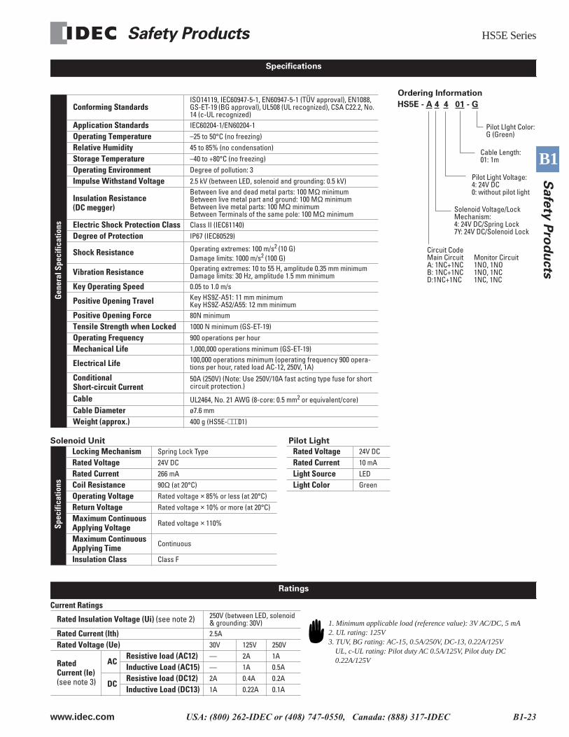
Solenoid Unit Pilot Light
Current Ratings
Gen
eral
Spe
cific
atio
ns
Conforming Standards
ISO14119, IEC60947-5-1, EN60947-5-1 (TÜV approval), EN1088, GS-ET-19 (BG approval), UL508 (UL recognized), CSA C22.2, No. 14 (c-UL recognized)
Application Standards
IEC60204-1/EN60204-1
Operating Temperature
–25 to 50°C (no freezing)
Relative Humidity
45 to 85% (no condensation)
Storage Temperature
–40 to +80°C (no freezing)
Operating Environment
Degree of pollution: 3
Impulse Withstand Voltage
2.5 kV (between LED, solenoid and grounding: 0.5 kV)
Insulation Resistance(DC megger)
Between live and dead metal parts: 100 M
Ω
minimumBetween live metal part and ground: 100 M
Ω
minimumBetween live metal parts: 100 M
Ω
minimumBetween Terminals of the same pole: 100 M
Ω
minimum
Electric Shock Protection Class
Class II (IEC61140)
Degree of Protection
IP67 (IEC60529)
Shock Resistance
Operating extremes: 100 m/s
2
(10 G)Damage limits: 1000 m/s
2
(100 G)
Vibration Resistance
Operating extremes: 10 to 55 H, amplitude 0.35 mm minimumDamage limits: 30 Hz, amplitude 1.5 mm minimum
Key Operating Speed
0.05 to 1.0 m/s
Positive Opening Travel
Key HS9Z-A51: 11 mm minimumKey HS9Z-A52/A55: 12 mm minimum
Positive Opening Force
80N minimum
Tensile Strength when Locked
1000 N minimum (GS-ET-19)
Operating Frequency
900 operations per hour
Mechanical Life
1,000,000 operations minimum (GS-ET-19)
Electrical Life
100,000 operations minimum (operating frequency 900 opera-tions per hour, rated load AC-12, 250V, 1A)
ConditionalShort-circuit Current
50A (250V) (Note: Use 250V/10A fast acting type fuse for short circuit protection.)
Cable
UL2464, No. 21 AWG (8-core: 0.5 mm
2
or equivalent/core)
Cable Diameter
ø7.6 mm
Weight (approx.)
400 g (HS5E-
∗∗∗
01)
Spec
ifica
tions
Locking Mechanism
Spring Lock Type
Rated Voltage
24V DC
Rated Voltage
24V DC
Rated Current
10 mA
Rated Current
266 mA
Light Source
LED
Coil Resistance
90
Ω
(at 20°C)
Light Color
Green
Operating Voltage
Rated voltage
×
85% or less (at 20°C)
Return Voltage
Rated voltage
×
10% or more (at 20°C)
Maximum Continuous Applying Voltage
Rated voltage
×
110%
Maximum Continuous Applying Time
Continuous
Insulation Class
Class F
Rated Insulation Voltage (Ui)
(see note 2)
250V (between LED, solenoid & grounding: 30V)
Rated Current (Ith)
2.5A
Rated Voltage (Ue)
30V 125V 250V
RatedCurrent (Ie)
(see note 3)
ACResistive load (AC12)
— 2A 1A
Inductive Load (AC15)
— 1A 0.5A
DCResistive load (DC12)
2A 0.4A 0.2A
Inductive Load (DC13)
1A 0.22A 0.1A
Ordering Information
Solenoid Voltage/Lock Mechanism:4: 24V DC/Spring Lock7Y: 24V DC/Solenoid Lock
HS5E - A 4 4 01 - G
Pilot LIght Color:G (Green)
Cable Length:01: 1m
Pilot Light Voltage: 4: 24V DC0: without pilot light
Circuit CodeMain Circuit Monitor CircuitA: 1NC+1NC 1NO, 1NOB: 1NC+1NC 1NO, 1NCD:1NC+1NC 1NC, 1NC
Specifications
Ratings
1. Minimum applicable load (reference value): 3V AC/DC, 5 mA2. UL rating: 125V3. TUV, BG rating: AC-15, 0.5A/250V, DC-13, 0.22A/125V
UL, c-UL rating: Pilot duty AC 0.5A/125V, Pilot duty DC 0.22A/125V
HS5E Series
Safety Products
B1-24
www.idec.com
USA: (800) 262-IDEC or (408) 747-0550, Canada: (888) 317-IDEC
B1
S
afe
ty P
rod
ucts
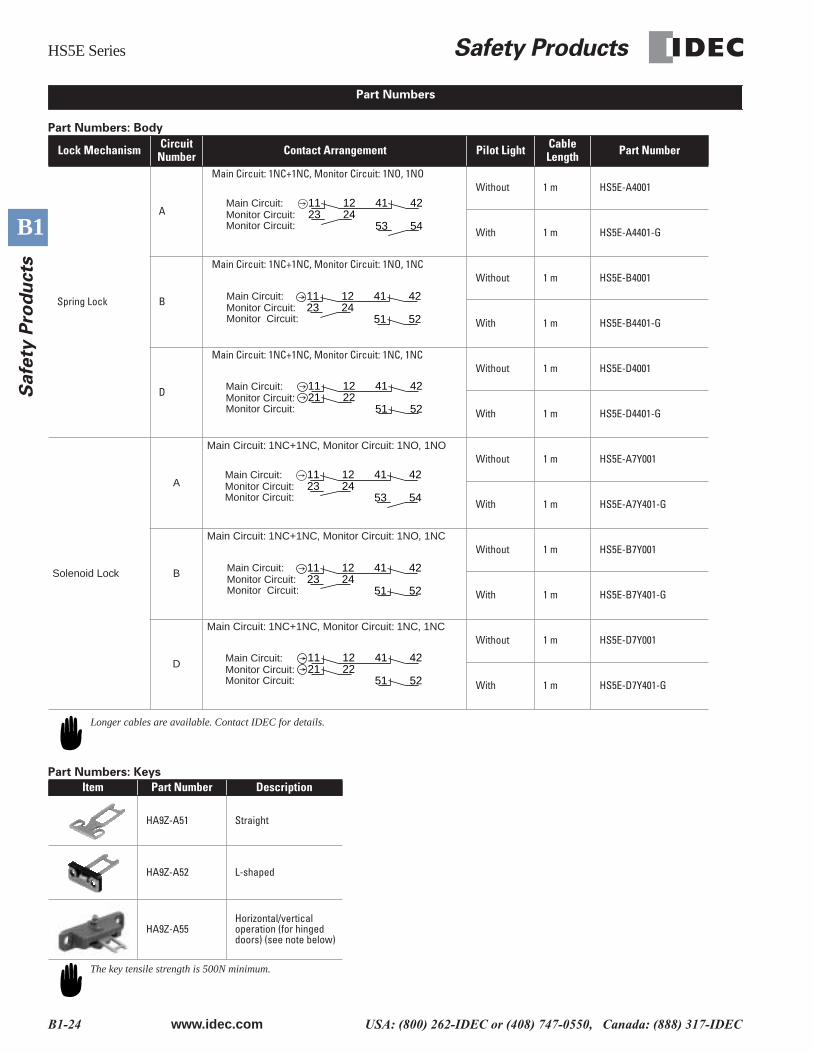
Part Numbers: Body
Part Numbers: Keys
Lock Mechanism CircuitNumber Contact Arrangement Pilot Light Cable
Length Part Number
Spring Lock
A
Main Circuit: 1NC+1NC, Monitor Circuit: 1NO, 1NOWithout 1 m HS5E-A4001
With 1 m HS5E-A4401-G
B
Main Circuit: 1NC+1NC, Monitor Circuit: 1NO, 1NCWithout 1 m HS5E-B4001
With 1 m HS5E-B4401-G
D
Main Circuit: 1NC+1NC, Monitor Circuit: 1NC, 1NCWithout 1 m HS5E-D4001
With 1 m HS5E-D4401-G
Solenoid Lock
A
Main Circuit: 1NC+1NC, Monitor Circuit: 1NO, 1NO
Without 1 m HS5E-A7Y001
With 1 m HS5E-A7Y401-G
B
Main Circuit: 1NC+1NC, Monitor Circuit: 1NO, 1NC
Without 1 m HS5E-B7Y001
With 1 m HS5E-B7Y401-G
D
Main Circuit: 1NC+1NC, Monitor Circuit: 1NC, 1NC
Without 1 m HS5E-D7Y001
With 1 m HS5E-D7Y401-G
Item Part Number Description
HA9Z-A51 Straight
HA9Z-A52 L-shaped
HA9Z-A55Horizontal/vertical operation (for hinged doors) (see note below)
Part Numbers
241123
12 4241
5453
Main Circuit:Monitor Circuit:Monitor Circuit:
51 52
41 42122311
24Main Circuit:Monitor Circuit:Monitor Circuit:
41121121 22
51 52
42Main Circuit:Monitor Circuit:Monitor Circuit:
241123
12 4241
5453
Main Circuit:Monitor Circuit:Monitor Circuit:
51 52
41 42122311
24Main Circuit:Monitor Circuit:Monitor Circuit:
41121121 22
51 52
42Main Circuit:Monitor Circuit:Monitor Circuit:
Longer cables are available. Contact IDEC for details.
The key tensile strength is 500N minimum.
Safety Products
HS5E Series
www.idec.com
USA: (800) 262-IDEC or (408) 747-0550, Canada: (888) 317-IDEC B1-25
B1
Safe
ty P
rod
ucts
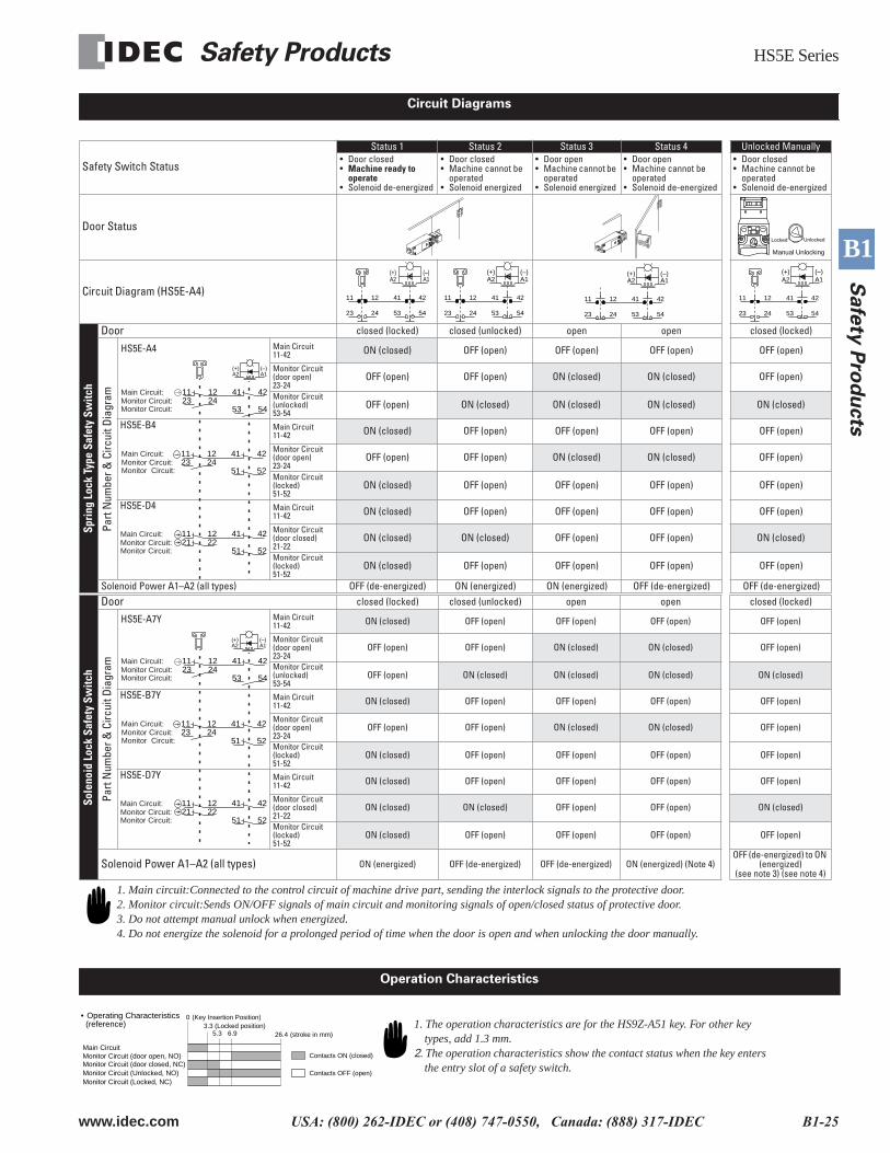
Safety Switch Status
Status 1 Status 2 Status 3 Status 4 Unlocked Manually• Door closed•
Machine ready to operate
• Solenoid de-energized
• Door closed• Machine cannot be
operated• Solenoid energized
• Door open• Machine cannot be
operated• Solenoid energized
• Door open• Machine cannot be
operated• Solenoid de-energized
• Door closed• Machine cannot be
operated• Solenoid de-energized
Door Status
Circuit Diagram (HS5E-A4)
Spri
ng L
ock
Type
Saf
ety
Switc
h
Door
closed (locked) closed (unlocked) open open closed (locked)
Part
Num
ber &
Circ
uit D
iagr
am
Main Circuit11-42
ON (closed) OFF (open) OFF (open) OFF (open) OFF (open)
Monitor Circuit(door open)23-24
OFF (open) OFF (open) ON (closed) ON (closed) OFF (open)
Monitor Circuit(unlocked)53-54
OFF (open) ON (closed) ON (closed) ON (closed) ON (closed)
HS5E-B4
Main Circuit11-42
ON (closed) OFF (open) OFF (open) OFF (open) OFF (open)
Monitor Circuit(door open)23-24
OFF (open) OFF (open) ON (closed) ON (closed) OFF (open)
Monitor Circuit(locked)51-52
ON (closed) OFF (open) OFF (open) OFF (open) OFF (open)
HS5E-D4
Main Circuit11-42
ON (closed) OFF (open) OFF (open) OFF (open) OFF (open)
Monitor Circuit(door closed)21-22
ON (closed) ON (closed) OFF (open) OFF (open) ON (closed)
Monitor Circuit(locked)51-52
ON (closed) OFF (open) OFF (open) OFF (open) OFF (open)
Solenoid Power A1–A2 (all types) OFF (de-energized) ON (energized) ON (energized) OFF (de-energized) OFF (de-energized)
Sole
noid
Loc
k Sa
fety
Sw
itch
Door
closed (locked) closed (unlocked) open open closed (locked)
Part
Num
ber &
Circ
uit D
iagr
am
Main Circuit11-42
ON (closed) OFF (open) OFF (open) OFF (open) OFF (open)
Monitor Circuit(door open)23-24
OFF (open) OFF (open) ON (closed) ON (closed) OFF (open)
Monitor Circuit(unlocked)53-54
OFF (open) ON (closed) ON (closed) ON (closed) ON (closed)
HS5E-B7Y
Main Circuit11-42
ON (closed) OFF (open) OFF (open) OFF (open) OFF (open)
Monitor Circuit(door open)23-24
OFF (open) OFF (open) ON (closed) ON (closed) OFF (open)
Monitor Circuit(locked)51-52
ON (closed) OFF (open) OFF (open) OFF (open) OFF (open)
HS5E-D7Y
Main Circuit11-42
ON (closed) OFF (open) OFF (open) OFF (open) OFF (open)
Monitor Circuit(door closed)21-22
ON (closed) ON (closed) OFF (open) OFF (open) ON (closed)
Monitor Circuit(locked)51-52
ON (closed) OFF (open) OFF (open) OFF (open) OFF (open)
Solenoid Power A1–A2 (all types)
ON (energized) OFF (de-energized) OFF (de-energized) ON (energized) (Note 4)OFF (de-energized) to ON
(energized)(see note 3) (see note 4)
Circuit Diagrams
Manual Unlocking
UnlockedLocked
11
23
42
54
12
24
41
53
(+)A2
(–)A1 A1
(–)A2(+)
53
41
24
12
54
42
23
11 11
23
42
54
12
24
41
53
(+)A2
(–)A1
11
23
42
54
12
24
41
53
(+)A2
(–)A1
241123
12 4241
5453
Main Circuit:Monitor Circuit:Monitor Circuit:
HS5E-A4
(+)A2
(–)A1
51 52
41 42122311
24Main Circuit:Monitor Circuit:Monitor Circuit:
41121121 22
51 52
42Main Circuit:Monitor Circuit:Monitor Circuit:
241123
12 4241
5453
Main Circuit:Monitor Circuit:Monitor Circuit:
HS5E-A7Y
(+)A2
(–)A1
51 52
41 42122311
24Main Circuit:Monitor Circuit:Monitor Circuit:
41121121 22
51 52
42Main Circuit:Monitor Circuit:Monitor Circuit:
1. Main circuit:Connected to the control circuit of machine drive part, sending the interlock signals to the protective door.2. Monitor circuit:Sends ON/OFF signals of main circuit and monitoring signals of open/closed status of protective door.3. Do not attempt manual unlock when energized.4. Do not energize the solenoid for a prolonged period of time when the door is open and when unlocking the door manually.
Operation Characteristics
26.4 5.3 6.9
• Operating Characteristics 3.3 (Locked position)
0
(stroke in mm)
(Key Insertion Position)
Contacts OFF (open)
Contacts ON (closed)
Monitor Circuit (Unlocked, NO)
Main CircuitMonitor Circuit (door open, NO)
Monitor Circuit (Locked, NC)
Monitor Circuit (door closed, NC)
(reference) 1. The operation characteristics are for the HS9Z-A51 key. For other key types, add 1.3 mm.
2. The operation characteristics show the contact status when the key enters the entry slot of a safety switch.

HS5E Series
Safety Products
B1-26
www.idec.com
USA: (800) 262-IDEC or (408) 747-0550, Canada: (888) 317-IDEC
B1
S
afe
ty P
rod
ucts
Keys
Key Mounting Reference Position
Dimensions & Mounting Hole Layouts
HS5E-**4*G Type (w/pilot light)Horizontal Mounting/Straight Key (HS9Z-A51)
Key Stop
33
20
4033
61.6
55
61.6
11±1
30
32.913.413.4
32.9
106
Slot Plug(Note)
RPRP26.4
6.25.25.26.2
26.4
20 35
11
20
Mounting Hole Layout
4-M4 Screws
6±1
(6.3)145.710636.2
41
2820
Key
2028
40
42.2
36.2 106145.7 (6.3)
20 35
11
Key StopKey
R2.2
20 to 22
R2.2
Vertical Mounting/L-shaped Key (HS9Z-A52)
Plug the unused key entry slot using the slot plug supplied with the keys.Mounting Hole Layout
Key Stop
40
20
3340
20
33
Slot Plug (Note)
13.4 13.432.927.7
11
3520
1 KeyKey Cover
7.6 ±1
106145.7 (6.3)(6.3)145.7
106
R2.2
R2.2
20 to 22
29.6
36.2
205
61.6
4-M4 Screws
106
RP40.3
1
3520
36.2
32.9RP
27.7 41.5
5
Key StopKey
61.6
Key Cover
12.6
±1
30
29.620
HS9Z-A51 Key
Key Stop
Safety Switch Door Stop
Door Stop HS9Z-A52 Key
Key Cover
Key Stop
Safety SwitchAs shown in the figure on the right, the mounting reference posi-tion of the key when inserted in the safety switch is:HS9Z-A51: The key lightly touches the key stop placed on the
safety switch.HS9Z-A52: The key cover lightly touches the key stop placed
on the safety switch.After mounting the key, remove the key stop from the safety switch.
Straight type (HS9Z-A51)
Note: Key Stop (supplied with the key)
10
6.2 32.4
4-R 2
.2
15 2628 20
0.85.2(6)
6.4
2 2
2-ø4.41.6
30 28
0.84.5
15 20
332 7.27.2
• Key Mounting Hole Layout (straight, L-shaped)2-M4 Screw 20
L-shaped type (HS9Z-A52)
All dimensions in mm.
Safety Products
HS5E Series
www.idec.com USA: (800) 262-IDEC or (408) 747-0550, Canada: (888) 317-IDEC B1-27
B1
Safe
ty P
rod
ucts
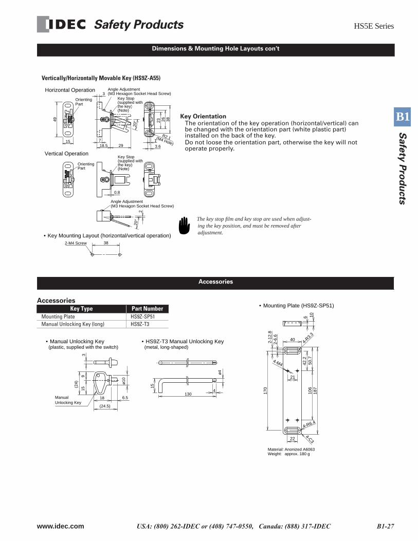
Accessories
Key Type Part NumberMounting Plate HS9Z-SP51Manual Unlocking Key (long) HS9Z-T3
OrientingPart
Angle Adjustment(M3 Hexagon Socket Head Screw)
Angle Adjustment(M3 Hexagon Socket Head Screw)
Vertical Operation
Horizontal Operation3
3.61(M4 Hole)
R2.1
23 26 38
Key Stop(supplied withthe key)(Note)
Key Stop(supplied withthe key)(Note)
0.8
220
°20
°
382-M4 Screw
• Key Mounting Layout (horizontal/vertical operation)
718.5 29
OrientingPart
49
15
Key OrientationThe orientation of the key operation (horizontal/vertical) can be changed with the orientation part (white plastic part) installed on the back of the key.Do not loose the orientation part, otherwise the key will not operate properly.
The key stop film and key stop are used when adjust-ing the key position, and must be removed after adjustment.
Vertically/Horizontally Movable Key (HS9Z-A55)
Dimensions & Mounting Hole Layouts con’t
Accessories
2-12
.82-
6.6
4-M4
4-R3.
3
6 10
40
170
106
187
50.7
42.2
224-C3
21
4-R6.4
• Mounting Plate (HS9Z-SP51)
Material: Anonized A6063Weight: approx. 180 g
ManualUnlocking Key
• Manual Unlocking Key (plastic, supplied with the switch)
• HS9Z-T3 Manual Unlocking Key (metal, long-shaped)
315
9
18
(24.5)
6.5
(24) ø
10
4130
15
ø4
HS5E Series Safety Products
B1-28 www.idec.com USA: (800) 262-IDEC or (408) 747-0550, Canada: (888) 317-IDEC
B1
Safe
ty P
rod
ucts
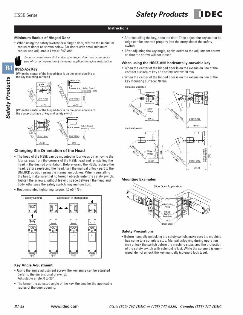
Minimum Radius of Hinged Door
• When using the safety switch for a hinged door, refer to the minimum radius of doors as shown below. For doors with small minimum radius, use adjustable keys (HS9Z-A55).
Changing the Orientation of the Head• The head of the HS5E can be mounted in four ways by removing the
four screws from the corners of the HS5E head and reinstalling the head in the desired orientation. Before wiring the HS5E, replace the head. Before replacing the head, turn the manual unlock part to the UNLOCK position using the manual unlock key. When reinstalling the head, make sure that no foreign objects enter the safety switch. Tighten the screws, without leaving space between the head and body, otherwise the safety switch may malfunction.
• Recommended tightening torque: 1.0 ±0.1 N·m
Key Angle Adjustment
• Using the angle adjustment screw, the key angle can be adjusted (refer to the dimensional drawing).Adjustable angle: 0 to 20°
• The larger the adjusted angle of the key, the smaller the applicable radius of the door opening.
• After installing the key, open the door. Then adjust the key so that its edge can be inserted properly into the entry slot of the safety switch.
• After adjusting the key angle, apply loctite to the adjustment screw so that the screw will not loosen.
When using the HS9Z-A55 horizontally-movable key
• When the center of the hinged door is on the extension line of the contact surface of key and safety switch: 50 mm
• When the center of the hinged door is on the extension line of the key mounting surface: 70 mm
Mounting Examples
Safety Precautions
• Before manually unlocking the safety switch, make sure the machine has come to a complete stop. Manual unlocking during operation may unlock the switch before the machine stops, and the protection of the safety switch with solenoid is lost. While the solenoid is ener-gized, do not unlock the key manually (solenoid lock type).
Instructions
Because deviation or dislocation of a hinged door may occur, make sure of correct operation of the actual application before installation.
Door HingeDoor Hinge
(231
)
Safety SwitchMounting Holes
(41.5) (40.3)
Minim
um
Radius230 m
m
Minim
um R
adius
260 mm
Door Hinge
(161
)
(35)
Safety SwitchMounting Holes190 m
mM
inimum
RadiusDoor Hinge
(36.2)
Minim
um
Radius
170 mm
HS9Z-A52 Key(When the center of the hinged door is on the extension line of the key mounting surface.)
(When the center of the hinged door is on the extension line of the contact surface of key and safety switch.
Orientation is changeable.Factory Setting
(58)
Saf
ety
Sw
itch
Mou
ntin
g H
ole
(55.5)
(36.2)
Door Hinge
DoorHinge50 mm
Minimum Radius70 mm
Vertical Operation
Horizontal Operation
(55.5)
Minimum Radius
70 mm(3
8)
Saf
ety
Sw
itch
Mou
ntin
g H
ole
(36.2)
Minimum Radius
50 mm
DoorHinge
Door Hinge
Minimum Radius
HS9Z-A51Keys
Door
HS5ESafety
Switches
Door Stop
Slide Door Application
Latch
Safety Products HS5E Series
www.idec.com USA: (800) 262-IDEC or (408) 747-0550, Canada: (888) 317-IDEC B1-29
B1
Safe
ty P
rod
ucts
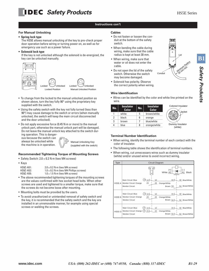
For Manual Unlocking
• Spring lock typeThe HS5E allows manual unlocking of the key to pre-check proper door operation before wiring or turning power on, as well as for emergency use such as a power failure.
• Solenoid lock typeIf the key is not unlocked although the solenoid is de-energized, the key can be unlocked manually.
Recommended Tightening Torque of Mounting Screws
• Safety Switch: 2.0 ± 0.2 N·m (two M4 screws)• Keys
HS9Z-A51: 2.0 ± 0.2 N·m (two M4 screws)HS9Z-A52: 1.0 ± 0.2 N·m (two M4 Phillips screws)HS9Z-A55: 1.0 ± 1.5 N·m (two M4 screws)
• The above recommended tightening torques of the mounting screws are the values confirmed with hex socket head bolts. When other screws are used and tightened to a smaller torque, make sure that the screws do not become loose after mounting.
• Mounting bolts must be provided by the users.• To avoid unauthorized or unintended removal of safety switch and
the key, it is recommended that the safety switch and the key are installed in an unremovable manner, for example using special screws or welding the screws.
Cables
Wire Identification
• Wires can be identified by the color and white line printed on the wire.
Terminal Number Identification
• When wiring, identify the terminal number of each contact with the color of insulator.
• The following table shows the identification of terminal numbers.• When wiring, cut unnecessary wires such as dummy insulator
(white) and/or unused wires to avoid incorrect wiring.
Instructions con’t
Locked UnlockedUnlockedLocked
Locked Position Manual Unlocked Position
LOCK UNLOCK
Manual Unlocking Key
(supplied with the switch)
• To change from the locked to the manual unlocked position as shown above, turn the key fully 90° using the proprietary key supplied with the switch.
• Using the safety switch with the key not fully turned (less than 90°) may cause damage to the switch or errors (when manually unlocked, the switch will keep the main circuit disconnected and the door unlocked).
• Do not apply excessive force (0.45 N·m or more) to the manual unlock part, otherwise the manual unlock part will be damaged. Do not leave the manual unlock key attached to the switch dur-ing operation. This is danger-ous because the switch can always be unlocked while the machine is in operation.
30 mm m
in.
ConduitMinim
um Radius
Lid
• Do not fasten or loosen the con-duit at the bottom of the safety switch.
• When bending the cable during wiring, make sure that the cable radius is kept at least 30 mm.
• When wiring, make sure that water or oil does not enter the cable.
• Do not open the lid of the safety switch. Otherwise the switch may become damaged.
• Solenoid has polarity. Observe the correct polarity when wiring.
Colored Insulator
Jacket
Dummy Insulator(white)
453
2
6
P
78
No. Insulator Color No. Insulator
Color1 white 5 brown/white2 black 6 orange3 brown 7 blue/white4 blue 8 orange/white
Blue/White
Blue/White
Blue/White
Brown/White
Brown/White
Brown/White
Main Circuit: Blue
Monitor Circuit: Orange
Monitor Circuit:
Main Circuit: Blue
Monitor Circuit: Orange
Monitor Circuit:
Main Circuit: Blue
Monitor Circuit: Orange
Monitor Circuit:
HS5E-A
HS5E-B
HS5E-D
Black
Circuit DiagramType
Orange/White
Orange/White
Orange/White
Brown
Brown
Brown 51 52
41 4212
21
11
22
24
11
23
12 4241
5251
(–)
53 54
(+)
41 4212
23
11
24
A2White A1
Safety Products Precautions
www.idec.com USA: (800) 262-IDEC or (408) 747-0550, Canada: (888) 317-IDEC B1-43
B1
Safe
ty P
rod
ucts
• In order to avoid electric shock or a fire, turn the power off before installation, removal, wire connection, maintenance, or inspection of the switch.
• If relays are used in the circuit between the safety switch and the load, consider degrees of the danger and use safety relays, since welded or sticking contacts of standard relays may invalidate the functions of the safety switch.
• Do not place a PLC in the circuit between the safety switch and the load. The safety security can be endangered in the event of a mal-function of the PLC.
• Do not disassemble or modify the switch. It may cause a breakdown or an accident.
• Regardless of door types, do not use the safety switch as a door stop. Install a mechanical door stop at the end of the door to protect the safety switch against excessive force.
• Do not apply an excessive shock to the switch when opening or closing the door.
• A shock to the door exceeding 1,000 m/sec2 (approx. 100G) may cause the contacts of the switch to chatter, and a malfunction of the switch may occur.
• For connection of wires, unscrew the cover. Unnecessary loosening of other screws may cause a malfunction of the switch.
• Prevent foreign objects such as dust and liquids from entering the switch while connecting a conduit or wiring.
• If the operating atmosphere is contaminated, use a protective cover to prevent the entry of foreign objects into the switch through the actuator entry slots.
• Entry of a considerable amount of foreign objects into the switch may affect the mechanism of the switch and cause a breakdown.
• Do not store the switches in a dusty, humid, or organic-gas atmo-sphere.
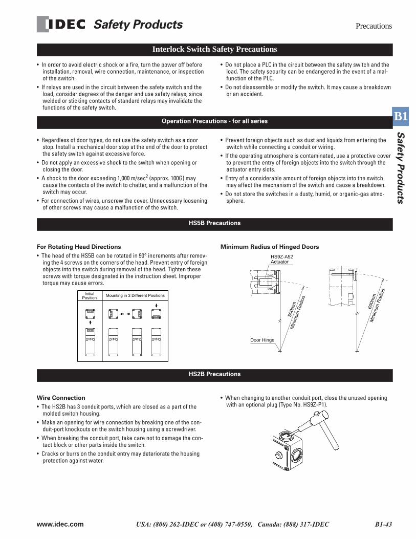
For Rotating Head Directions
• The head of the HS5B can be rotated in 90° increments after remov-ing the 4 screws on the corners of the head. Prevent entry of foreign objects into the switch during removal of the head. Tighten these screws with torque designated in the instruction sheet. Improper torque may cause errors.
Minimum Radius of Hinged Doors
Wire Connection
• The HS2B has 3 conduit ports, which are closed as a part of the molded switch housing.
• Make an opening for wire connection by breaking one of the con-duit-port knockouts on the switch housing using a screwdriver.
• When breaking the conduit port, take care not to damage the con-tact block or other parts inside the switch.
• Cracks or burrs on the conduit entry may deteriorate the housing protection against water.
• When changing to another conduit port, close the unused opening with an optional plug (Type No. HS9Z-P1).
Interlock Switch Safety Precautions
Operation Precautions - for all series
HS5B Precautions
InitialPosition Mounting in 3 Different Positions
Door Hinge
Min
imum
Rad
ius
500m
m
Min
imum
Rad
ius
600m
m
HS9Z-A52Actuator
HS2B Precautions
Precautions Safety Products
B1-44 www.idec.com USA: (800) 262-IDEC or (408) 747-0550, Canada: (888) 317-IDEC
B1
Safe
ty P
rod
ucts
Wire Connection
• Make an opening for wire connection by breaking one of the con-duit-port knockouts on the switch housing using a screwdriver.
• Before breaking the knockout, temporarily remove the connector-fix-ing lock nut from the switch.
• When breaking the knockout, take care not to damage the contact block or other parts inside the switch.
• Cracks or burrs on the conduit entry may deteriorate the housing protection.
• When changing to the other conduit port, close the unused opening with an optional plug (accessory).
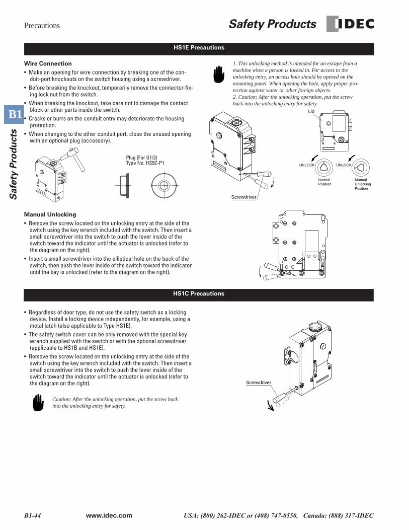
Manual Unlocking
• Remove the screw located on the unlocking entry at the side of the switch using the key wrench included with the switch. Then insert a small screwdriver into the switch to push the lever inside of the switch toward the indicator until the actuator is unlocked (refer to the diagram on the right).
• Insert a small screwdriver into the elliptical hole on the back of the switch, then push the lever inside of the switch toward the indicator until the key is unlocked (refer to the diagram on the right).
1. This unlocking method is intended for an escape from a machine when a person is locked in. For access to the unlocking entry, an access hole should be opened on the mounting panel. When opening the hole, apply proper pro-tection against water or other foreign objects.2. Caution: After the unlocking operation, put the screw back into the unlocking entry for safety.
• Regardless of door type, do not use the safety switch as a locking device. Install a locking device independently, for example, using a metal latch (also applicable to Type HS1E).
• The safety switch cover can be only removed with the special key wrench supplied with the switch or with the optional screwdriver (applicable to HS1B and HS1E).
• Remove the screw located on the unlocking entry at the side of the switch using the key wrench included with the switch. Then insert a small screwdriver into the switch to push the lever inside of the switch toward the indicator until the actuator is unlocked (refer to the diagram on the right).
Caution: After the unlocking operation, put the screw back into the unlocking entry for safety.
HS1E Precautions
Type No.: HS9Z-P1Plug (For G1/2)Plug (For G1/2)
Type No. HS9Z-P1
Screwdriver
Lid
UNLOCK UNLOCK
NormalPosition
ManualUnlockingPosition
HS1C Precautions
Screwdriver
Safety Products Precautions
www.idec.com USA: (800) 262-IDEC or (408) 747-0550, Canada: (888) 317-IDEC B1-45
B1
Safe
ty P
rod
ucts
Applicable Crimping Terminals
• (Refer to the Crimping Terminal 1 or 2 shown in the drawing below.)• HS1C
Terminals No. 1 to 6: Use solid or stranded wires only (crimping ter-minals not applicable).Terminals No. 7 and 8: Crimping Terminal 1Ground Terminal: Crimping Terminal 2
• HS1BGround Terminal: Crimping Terminal 2Other Terminals: Crimping Terminal 1HS2B, HS5B, and HS1ECrimping Terminal 1
Use an insulation tube on the crimping terminal.
Installation Examples (see the diagrams below)
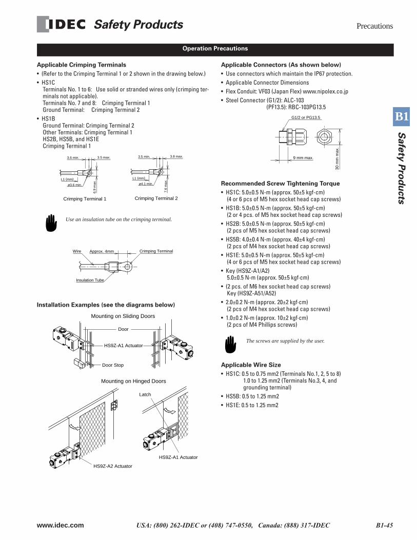
Applicable Connectors (As shown below)
• Use connectors which maintain the IP67 protection. • Applicable Connector Dimensions• Flex Conduit: VF03 (Japan Flex) www.nipolex.co.jp• Steel Connector (G1/2): ALC-103
(PF13.5): RBC-103PG13.5
Recommended Screw Tightening Torque
• HS1C: 5.0±0.5 N-m (approx. 50±5 kgf-cm)(4 or 6 pcs of M5 hex socket head cap screws)
• HS1B: 5.0±0.5 N-m (approx. 50±5 kgf-cm)(2 or 4 pcs. of M5 hex socket head cap screws)
• HS2B: 5.0±0.5 N-m (approx. 50±5 kgf-cm)(2 pcs of M5 hex socket head cap screws)
• HS5B: 4.0±0.4 N-m (approx. 40±4 kgf-cm)(2 pcs of M4 hex socket head cap screws)
• HS1E: 5.0±0.5 N-m (approx. 50±5 kgf-cm)(4 or 6 pcs of M5 hex socket head cap screws)
• Key (HS9Z-A1/A2)5.0±0.5 N-m (approx. 50±5 kgf·cm)
• (2 pcs. of M6 hex socket head cap screws)Key (HS9Z-A51/A52)
• 2.0±0.2 N-m (approx. 20±2 kgf·cm)(2 pcs of M4 hex socket head cap screws)
• 1.0±0.2 N-m (approx. 10±2 kgf·cm)(2 pcs of M4 Phillips screws)
The screws are supplied by the user.
Applicable Wire Size
• HS1C: 0.5 to 0.75 mm2 (Terminals No.1, 2, 5 to 8) 1.0 to 1.25 mm2 (Terminals No.3, 4, and grounding terminal)
• HS5B: 0.5 to 1.25 mm2• HS1E: 0.5 to 1.25 mm2
Operation Precautions
7.6
max
.
3.5 min. 3.8 max.
ø4.1 min.
L1 (mm)
Crimping Terminal 2Crimping Terminal 1
6.9
max
.
3.6 min. 3.5 max.
ø3.6 min.
L1 (mm)
Approx. 4mm Crimping TerminalWire
Insulation Tube
Door Stop
HS9Z-A1 Actuator
Door
Mounting on Sliding Doors
Latch
HS9Z-A1 Actuator
HS9Z-A2 Actuator
Mounting on Hinged Doors
G1/2 or PG13.5
9 mm max.
30 m
m m
ax.