Safety Manual SH 3963 EN - samsongroup.com · The Type 3963 Solenoid Valve converts binary voltage...
28
SH 3963 EN Translation of original instructions Type 3963 Solenoid Valve Edition April 2015
Transcript of Safety Manual SH 3963 EN - samsongroup.com · The Type 3963 Solenoid Valve converts binary voltage...

SH 3963 EN
Translation of original instructions
Type 3963 Solenoid Valve
Edition April 2015

Definition of signal words
Hazardous situations which, if not avoided, will result in death or serious injury
Hazardous situations which, if not avoided, could result in death or serious injury
Property damage message or malfunction
Additional information
Recommended action
DANGER!
WARNING!
NOTICE!
Note
Tip
2 SH 3963 EN

SH 3963 EN 3
Purpose of this manualThe Safety Manual SH 3963 contains information relevant for the use of the Type 3963 Sole-noid Valve in safety-instrumented systems according to IEC 61508 and IEC 61511. The safe-ty manual is intended for planners, constructors and operators of safety-instrumented sys-tems.
Risk of malfunction due to incorrect mounting, connection or start-up of the device.Refer to the Mounting and Operating Instructions EB 3963 on how to mount the positioner, perform the electric and pneumatic connections as well as start up the device.Observe the warnings and safety instructions written in the Mounting and Operating Instruc-tions EB 3963.
Further documentationThe documents listed below contain descriptions of the start-up, functioning and operation of the solenoid valve. You can download these documents from the SAMSON website. The doc-uments marked with an asterisk (*) are supplied with the solenoid valve either in printed or electronic form.u T 3963: Data sheetu EB 3963*: Mounting and operating instructions
In addition to the solenoid valve documentation, observe the documentation for the pneumat-ic actuator, valve and other valve accessories.
NOTICE!
Note

Contents
4 SH 3963 EN
1 Scope ...........................................................................................................5 General ........................................................................................................5 Use in safety-instrumented systems ..................................................................5 Versions and ordering data ............................................................................5 Article code ...................................................................................................6 Mounting versions ........................................................................................112 Technical data .............................................................................................123 Safety-related functions ...............................................................................19 Emergency venting .......................................................................................19 Fail-safe action ............................................................................................194 Mounting, connection and start-up ...............................................................195 Required conditions .....................................................................................21 Selection .....................................................................................................21 Mechanical and pneumatic installation ..........................................................21 Electrical installation .....................................................................................226 Proof testing ................................................................................................23 Function testing ............................................................................................23 Visual inspection to avoid systematic failure ...................................................247 Repairs .......................................................................................................258 Safety-relateddataandcertificates ..............................................................26

SH 3963 EN 5
Scope
1 ScopeGeneralThe Type 3963 Solenoid Valve converts binary voltage signals into pneumatic control signals. It is used to control pneumatic rotary and linear actuators with spring-return mechanism.
Use in safety-instrumented systemsObserving the requirements of IEC 61508, the systematic capability of the solenoid valve for emergency venting as a component in safety-instrumented systems is given.Use of the solenoid valve is possible on observing the requirements of IEC 61511 and the re-quired hardware fault tolerance in safety-instrumented systems up to SIL 2 (single device/HFT = 0) and SIL 3 (redundant configuration/HFT = 1).The individual safety functions of the solenoid valve are to be regarded as Type A elements in accordance with IEC 61508-2.
The architecture and the interval between proof tests must be changed accordingly for a higher safety integrity level.
Versions and ordering dataAll versions of the solenoid valve marked with the prefix SIL are suitable for use in safety-in-strumented systems. The article code written on the nameplate (see page 6 ff.) provides details on the optional equipment of the solenoid valve.
Note
6 SH 3963 EN
Scope
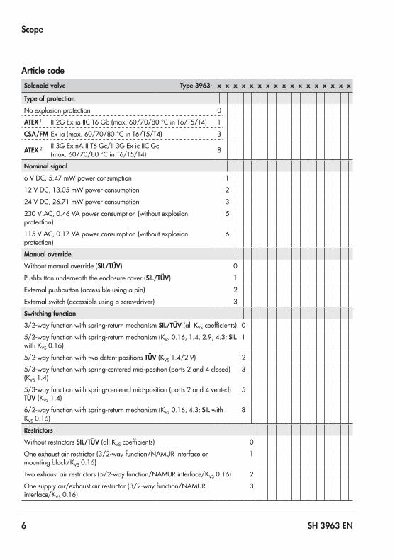
Article codeSolenoid valve Type 3963- x x x x x x x x x x x x x x x x x
Type of protectionNo explosion protection 0
ATEX 1) II 2G Ex ia IIC T6 Gb (max. 60/70/80 °C in T6/T5/T4) 1
CSA/FM Ex ia (max. 60/70/80 °C in T6/T5/T4) 3
ATEX 2) II 3G Ex nA II T6 Gc/II 3G Ex ic IIC Gc (max. 60/70/80 °C in T6/T5/T4) 8
Nominal signal6 V DC, 5.47 mW power consumption 1
12 V DC, 13.05 mW power consumption 2
24 V DC, 26.71 mW power consumption 3
230 V AC, 0.46 VA power consumption (without explosion protection)
5
115 V AC, 0.17 VA power consumption (without explosion protection)
6
Manual overrideWithout manual override (SIL/TÜV) 0
Pushbutton underneath the enclosure cover (SIL/TÜV) 1
External pushbutton (accessible using a pin) 2
External switch (accessible using a screwdriver) 3
Switching function3/2-way function with spring-return mechanism SIL/TÜV (all KVS coefficients) 0
5/2-way function with spring-return mechanism (KVS 0.16, 1.4, 2.9, 4.3; SIL with KVS 0.16)
1
5/2-way function with two detent positions TÜV (KVS 1.4/2.9) 2
5/3-way function with spring-centered mid-position (ports 2 and 4 closed) (KVS 1.4)
3
5/3-way function with spring-centered mid-position (ports 2 and 4 vented) TÜV (KVS 1.4)
5
6/2-way function with spring-return mechanism (KVS 0.16, 4.3; SIL with KVS 0.16)
8
RestrictorsWithout restrictors SIL/TÜV (all KVS coefficients) 0
One exhaust air restrictor (3/2-way function/NAMUR interface or mounting block/KVS 0.16)
1
Two exhaust air restrictors (5/2-way function/NAMUR interface/KVS 0.16) 2
One supply air/exhaust air restrictor (3/2-way function/NAMUR interface/KVS 0.16)
3

SH 3963 EN 7
Scope
Solenoid valve Type 3963- x x x x x x x x x x x x x x x x x
AttachmentNAMUR interface according to VDI/VDE 3845 SIL/TÜV (all KVS coefficients) 0
Threaded connection for rail, wall or pipe mounting SIL/TÜV (KVS 0.16, 0.32, 1.4, 4.3)
1
NAMUR ribs according to IEC 60534-6-1 SIL/TÜV (KVS 0.32) 2
Mounting block for Type 3277 Linear Actuator SIL/TÜV (KVS 0.16, 0.32) 3
Type 3963 (flange), only as spare part (KVS 0.01/0.16) 4
KVS 3)
0.16 SIL/TÜV 1
0.32 SIL/TÜV 2
1.4 TÜV 3
4.3 SIL/TÜV 4
0.01 (as spare part) 5
2.9 (NAMUR interface) 6
2.0 SIL/TÜV (NAMUR interface) 7
Pneumatic connectionG ¼ (KVS 0.16, 0.32, 1.4, 2.0) 0
¼ NPT (KVS 0.16, 0.32, 1.4, 2.0) 1
G ½ (KVS 2.9, 4.3) 2
½ NPT (KVS 2.9, 4.3) 3
Without (pilot valve as spare part/mounting block for Type 3277 Linear Actuator)
4
Air supplyInternal supply for actuators for on/off service 0
External pilot supply for actuators for throttling service 1
Electrical connectionBlanking plug M20x1.5 0 0
Cable gland M20x1.5, black polyamide 0 1
Cable gland M20x1.5, blue polyamide 1 1
Adapter M20x1.5 to ½ NPT (aluminum) 1 2
Cable gland M20x1.5 (CEAG), black polyamide 1 3
Cable gland M20x1.5, nickel-plated brass 1 4
Cable gland M20x1.5, nickel-plated brass, blue 1 5
Cable gland M20x1.5 (CEAG), blue polyamide 1 6
Cable gland M20x1.5 (Jacob), blue polyamide 1 7
Device connector according to DIN EN 175301-803, black polyamide 1) 2 3

8 SH 3963 EN
Scope
Solenoid valve Type 3963- x x x x x x x x x x x x x x x x x
Device connector with LED according to DIN EN 175301-803, black polyamide 1) 2 5
Adapter M20x1.5 to ½ NPT (stainless steel) 2 6
Degree of protectionIP 54 with polyethylene filter 0
IP 65 with filter check valve made of polyamide 1
IP 65 with filter check valve made of stainless steel 2
NEMA 4 with filter check valve made of polyamide 4
NEMA 4 with filter check valve made of stainless steel 5
Ambient temperature 5)
–20 to +80 °C 0
–45 to +80 °C 2
Safety functionWithout 0
SIL 6) 1
TÜV 7) 2
Special version 8)
Without 0 0 0
MaterialConnecting plate/booster valve enclosure made of 1.4404 on request 0 0 1
Explosion protectionNEPSI Ex ia 0 0 9
EAC GOST Ex ia 0 1 1
KCS Ex ia 0 1 3
STCC Ex ia 0 1 7
STCC Ex na 0 1 8
1) EC type examination certificate PTB 01 ATEX 20852) Statement of conformity PTB 01 ATEX 2086 X3) The air flow rate when p1 = 2.4 bar and p2 = 1.0 bar is calculated using the following formula:
Q = KVS x 36.22 in m³/h.4) The cable socket is not included in the scope of delivery (u EB 3963).5) The permissible ambient temperature of the solenoid valve depends on the permissible ambient temperature of the
components, type of protection and temperature class.6) SIL according to IEC 615087) Emergency release or locking of compressed air supply8) Further special versions on reques
SH 3963 EN 9
Scope
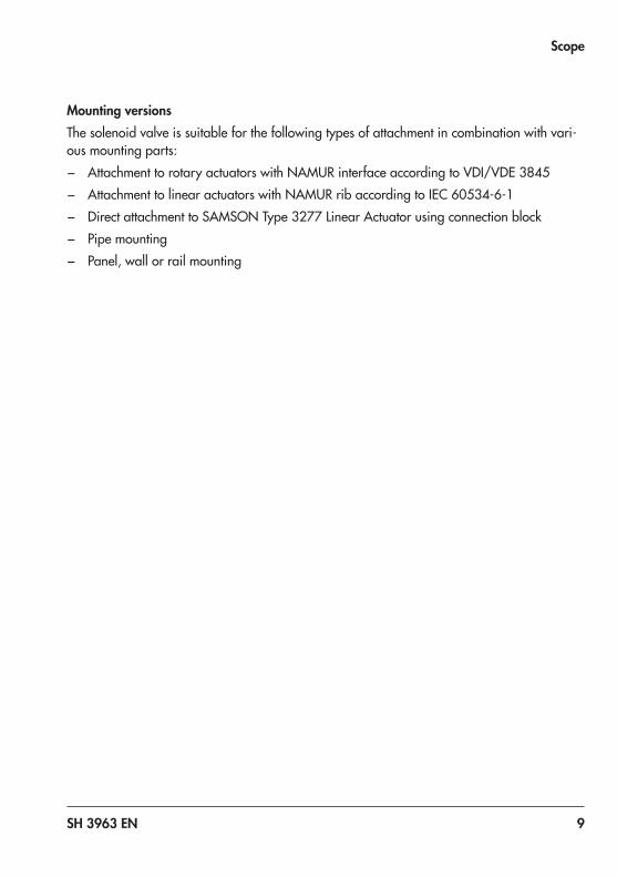
Mounting versionsThe solenoid valve is suitable for the following types of attachment in combination with vari-ous mounting parts: − Attachment to rotary actuators with NAMUR interface according to VDI/VDE 3845 − Attachment to linear actuators with NAMUR rib according to IEC 60534-6-1 − Direct attachment to SAMSON Type 3277 Linear Actuator using connection block − Pipe mounting − Panel, wall or rail mounting
10 SH 3963 EN
Technical data
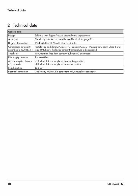
2 Technical dataGeneral dataDesign Solenoid with flapper/nozzle assembly and poppet valveActuation Electrically actuated on one side (see Electric data, page 11)Degree of protection IP 54 with filter, IP 65 with filter check valveCompressed air quality according to ISO 8573-1
Particle size and density: Class 4 · Oil content: Class 3 · Pressure dew point: Class 3 or at least 10 K below the lowest ambient temperature to be expected
Supply air Instrument air (free from corrosive substances) or nitrogenPilot supply pressure 1.4 to 6.0 barAir consumption (binary e/p converter)
≤10 l/h at 1.4 bar supply air in operating position, ≤80 l/h at 1.4 bar supply air in neutral position
Switching time ≤65 msElectrical connection Cable entry M20x1.5 to screw terminal, two pole or connector

SH 3963 EN 11
Technical data
Electric dataType 3963 -x1 -x2 -x3 -08 -07 -06 -05Nominal signalUN 6 V DC 12 V DC 24 V DC 24 V AC 48 V AC 115 V AC 230 V ACUmax 1) 27 V 25 V 32 V 36 V 80 V 130 V 255 VfN – 48 to 62 HzSwitching pointOn U+80 °C ≥4.8 V ≥9.6 V ≥18 V 19 to 36 V 42 to 80 V 82 to 130 V 183 to
255 VOn I+20 °C ≥1.41 mA ≥1.52 mA ≥1.57 mA ≥1.9 mA ≥1.9 mA ≥2.2 mA ≥2.6 mAOn P+20 °C ≥5.47 mW ≥13.05 mW ≥26.71 mW ≥0.04 VA ≥0.07 VA ≥0.17 VA ≥0.46 VAOff U–25 °C ≤1.0 V ≤2.4 V ≤4.7 V ≤4.5 V ≤9.0 V ≤18.0 V ≤36.0 VImpedanceR+20 °C 2.6 kΩ 5.5 kΩ 10.7 kΩ Approx.
10 kΩApprox. 24 kΩ
Approx. 40 kΩ
Approx. 80 kΩ
Temperature influence on R
0.4 %/°C 0.2 %/°C 0.1 %/°C 0.1 %/°C 0.1 %/°C 0.05 %/°C 0.03 %/°C
TypeofprotectionExiaIIC 2)foruseinhazardousareas(Zone 1)Type 3963 -11 -12 -13Nominal signalUN 6 V DC 12 V DC 24 V DCSee EC type examination certificate PTB 01 ATEX 2085 for maximum permissible values when connected to a certified intrinsically safe circuit.TypeofprotectionExnAII 3)foruseinhazardousareas(Zone 2)Type 3963 -81 -82 -83Nominal signalUN 6 V DC 12 V DC 24 V DCSee statement of conformity PTB 01 ATEX 2086 X for maximum permissible values when connected to a certified intrinsically safe circuit.1) Maximum permissible value at 100 % duty cycle. The maximum permissible value Ui applies to explosion-
protected versions.2) Marking II 2G Ex ia IIC T6 Gb (gases in Zone 1)3) Marking II 3G Ex nA II T6 Gc/II 3G Ex ic IIC T6 Gc (gases in Zone 2)

12 SH 3963 EN
Technical data
Solenoid valve with threaded connection, KVS 0.16/0.32Type 3963 -xxx0x11 -xxx0x12 -xxx1x11 -xxx8x11Switching function 3/2-way function 3/2-way function 5/2-way function 6/2-way functionKVS 1) 0.16 0.32 0.16 0.16Safety function SIL 2), TÜV 3) SIL 2), TÜV 3) SIL 2), TÜV 3) –Design Diaphragm switching element, soft seated, with return springMaterial Enclosure: Black polyamide
Connecting plate: Aluminum, powder coated, gray beige RAL 1019 or stainless steel 1.4404
Springs: Stainless steel 1.4310Screws: Stainless steel 1.4571Seals: Silicone rubber, PerbunanDiaphragms: Chloroprene rubber (–20 to +80 °C) or silicone rubber (–45 to
+80 °C)Operating medium Instrument air (free from corrosive substances) or nitrogen 4)
Air containing oil or non-corrosive gases 5)
Max. operating pressure 6.0 barOutput signal Operating pressurePneumatic connection G ¼ or ¼ NPTAmbient temperature 6) –20 to +80 °C (chloroprene rubber) or –45 to +80 °C (silicone rubber)Approx. weight 0.57 kg1) The air flow rate when p1 = 2.4 bar and p2 = 1.0 bar is calculated using the following formula:
Q = KVS x 36.22 in m³/h.2) SIL according to IEC 615083) Emergency release or locking of compressed air supply4) With internal pilot supply5) With external pilot supply6) The maximum permissible ambient temperature depends on the permissible ambient temperature of the cable
gland, type of protection and temperature class.
SH 3963 EN 13
Technical data
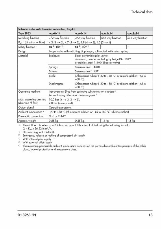
Solenoid valve with threaded connection, KVS 4.3Type 3963 -xxx0x14 -xxx0x14 -xxx1x14 -xxx8x14Switching function 3/2-way function 3/2-way function 5/2-way function 6/2-way functionKVS
1) (direction of flow) 4.3 (3 → 5), 4.7 (5 → 3), 1.9 (4 → 3), 1.5 (3 → 4)Safety function SIL 2), TÜV 3) SIL 2), TÜV 3) – –Design Poppet valve with switching diaphragm, soft seated, with return springMaterial Enclosure: Black polyamide (pilot valve),
aluminum, powder coated, gray beige RAL 1019, or stainless steel 1.4404 (booster valve)
Springs: Stainless steel 1.4310Screws: Stainless steel 1.4571Seals: Chloroprene rubber (–20 to +80 °C) or silicone rubber (–45 to
+80 °C)Diaphragms: Chloroprene rubber (–20 to +80 °C) or silicone rubber (–45 to
+80 °C)Operating medium Instrument air (free from corrosive substances) or nitrogen 4)
Air containing oil or non-corrosive gases 5)
Max. operating pressure (direction of flow)
10.0 bar (4 → 3, 3 → 5), 2.0 bar (as required)
Output signal Operating pressureAmbient temperature 6) –20 to +80 °C (chloroprene rubber) or –45 to +80 °C (silicone rubber)Pneumatic connection G ½ or ½ NPTApprox. weight 0.58 kg 0.58 kg 1.1 kg 1.1 kg1) The air flow rate when p1 = 2.4 bar and p2 = 1.0 bar is calculated using the following formula:
Q = KVS x 36.22 in m³/h.2) SIL according to IEC 615083) Emergency release or locking of compressed air supply4) With internal pilot supply5) With external pilot supply6) The maximum permissible ambient temperature depends on the permissible ambient temperature of the cable
gland, type of protection and temperature class.

14 SH 3963 EN
Technical data
Solenoid valve with NAMUR interface, KVS 0.16/0.32Type 3963 -xxx0x01 -xxx0x02 -xxx1x01 -xxx8x01Switching function 3/2-way function 3/2-way function 5/2-way function 6/2-way functionKVS 1) 0.16 0.32 0.16 0.16Safety function SIL 2), TÜV 3) SIL 2), TÜV 3) SIL 2), TÜV 3) –Design Diaphragm switching element, soft seated, with return springMaterial Enclosure: Black polyamide
Connecting plate: Black polyamide, aluminum, powder coated, gray beige RAL 1019, or stainless steel 1.4404
Springs: Stainless steel 1.4310Screws: Stainless steel 1.4571Seals: Silicone rubber, PerbunanDiaphragms: Chloroprene rubber (–20 to +80 °C) or silicone rubber (–45 to +80 °C)
Operating medium Instrument air (free from corrosive substances) or nitrogen 4) Air containing oil or non-corrosive gases 5)
Max. operating pressure 6.0 barOutput signal Operating pressurePneumatic connection G ¼ or ¼ NPT and NAMUR interface ¼" 7)
Ambient temperature 6) –20 to +80 °C (chloroprene rubber) or –45 to +80 °C (silicone rubber)Approx. weight 0.57 kg1) The air flow rate when p1 = 2.4 bar and p2 = 1.0 bar is calculated using the following formula:
Q = KVS x 36.22 in m³/h.2) SIL according to IEC 615083) Emergency release or locking of compressed air supply4) With internal pilot supply5) With external pilot supply6) The maximum permissible ambient temperature depends on the permissible ambient temperature of the cable
gland, type of protection and temperature class.7) NAMUR interface according to VDI/VDE 3845
SH 3963 EN 15
Technical data
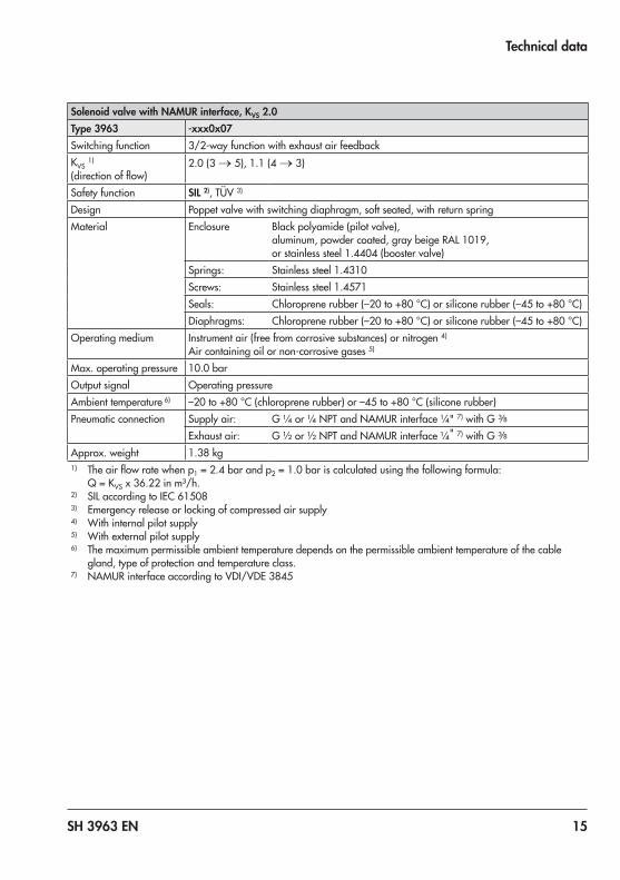
Solenoid valve with NAMUR interface, KVS 2.0Type 3963 -xxx0x07Switching function 3/2-way function with exhaust air feedbackKVS 1) (direction of flow)
2.0 (3 → 5), 1.1 (4 → 3)
Safety function SIL 2), TÜV 3)
Design Poppet valve with switching diaphragm, soft seated, with return springMaterial Enclosure Black polyamide (pilot valve),
aluminum, powder coated, gray beige RAL 1019, or stainless steel 1.4404 (booster valve)
Springs: Stainless steel 1.4310Screws: Stainless steel 1.4571Seals: Chloroprene rubber (–20 to +80 °C) or silicone rubber (–45 to +80 °C)Diaphragms: Chloroprene rubber (–20 to +80 °C) or silicone rubber (–45 to +80 °C)
Operating medium Instrument air (free from corrosive substances) or nitrogen 4) Air containing oil or non-corrosive gases 5)
Max. operating pressure 10.0 barOutput signal Operating pressureAmbient temperature 6) –20 to +80 °C (chloroprene rubber) or –45 to +80 °C (silicone rubber)Pneumatic connection Supply air: G ¼ or ¼ NPT and NAMUR interface ¼" 7) with G 3/8
Exhaust air: G ½ or ½ NPT and NAMUR interface ¼" 7) with G 3/8
Approx. weight 1.38 kg1) The air flow rate when p1 = 2.4 bar and p2 = 1.0 bar is calculated using the following formula:
Q = KVS x 36.22 in m³/h.2) SIL according to IEC 615083) Emergency release or locking of compressed air supply4) With internal pilot supply5) With external pilot supply6) The maximum permissible ambient temperature depends on the permissible ambient temperature of the cable
gland, type of protection and temperature class.7) NAMUR interface according to VDI/VDE 3845
16 SH 3963 EN
Technical data
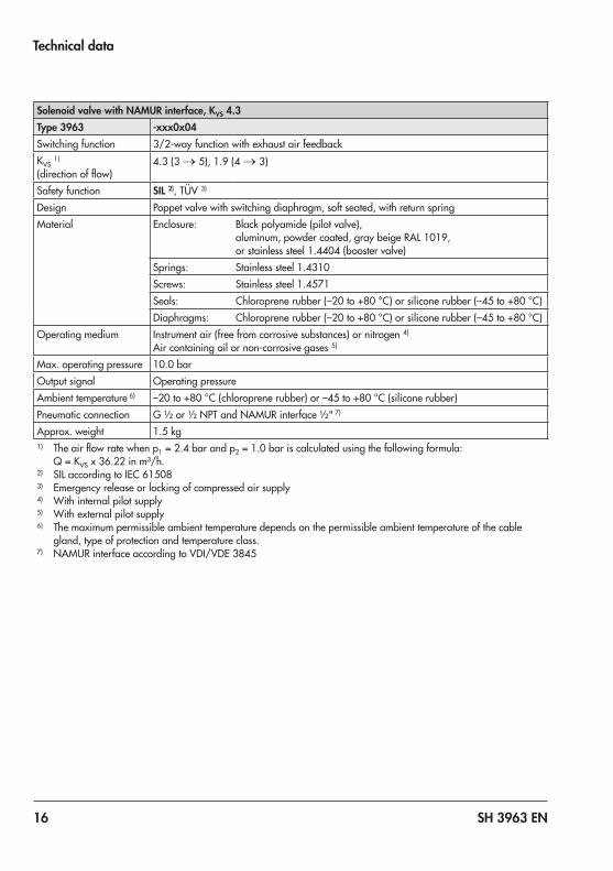
Solenoid valve with NAMUR interface, KVS 4.3Type 3963 -xxx0x04Switching function 3/2-way function with exhaust air feedbackKVS 1) (direction of flow)
4.3 (3 → 5), 1.9 (4 → 3)
Safety function SIL 2), TÜV 3)
Design Poppet valve with switching diaphragm, soft seated, with return springMaterial Enclosure: Black polyamide (pilot valve),
aluminum, powder coated, gray beige RAL 1019, or stainless steel 1.4404 (booster valve)
Springs: Stainless steel 1.4310Screws: Stainless steel 1.4571Seals: Chloroprene rubber (–20 to +80 °C) or silicone rubber (–45 to +80 °C)Diaphragms: Chloroprene rubber (–20 to +80 °C) or silicone rubber (–45 to +80 °C)
Operating medium Instrument air (free from corrosive substances) or nitrogen 4) Air containing oil or non-corrosive gases 5)
Max. operating pressure 10.0 barOutput signal Operating pressureAmbient temperature 6) –20 to +80 °C (chloroprene rubber) or –45 to +80 °C (silicone rubber)Pneumatic connection G ½ or ½ NPT and NAMUR interface ½" 7)
Approx. weight 1.5 kg1) The air flow rate when p1 = 2.4 bar and p2 = 1.0 bar is calculated using the following formula:
Q = KVS x 36.22 in m³/h.2) SIL according to IEC 615083) Emergency release or locking of compressed air supply4) With internal pilot supply5) With external pilot supply6) The maximum permissible ambient temperature depends on the permissible ambient temperature of the cable
gland, type of protection and temperature class.7) NAMUR interface according to VDI/VDE 3845

SH 3963 EN 17
Safety-related functions
3 Safety-related functionsEmergency ventingThe solenoid valve is energized by a binary voltage signal. Fail-safe action is triggered when no voltage signal (0 V AC/DC) is applied to terminals +81 and –82. The solenoid valve vents to the atmosphere and the actuator is vented as well (see Fig. 1, page 18).
Fail-safe actionFail-safe action is triggered by the solenoid valve and upon supply air failure.The solenoid valve fully discharges its pneumatic output to the atmosphere, causing the mounted actuator to be vented. As a result, the valve moves to the fail-safe position. The fail-safe position depends on how the springs are arranged in the pneumatic actuator (air-to-close or air-to-open).
4 Mounting, connection and start-upRefer to Mounting and Operating Instructions u EB 3963 on how to mount, perform the electric and pneumatic connections as well as start up the solenoid valve.Only use original mounting parts and accessories.

18 SH 3963 EN
Safety-related functions
Fig. 1: Functional diagram showing emergency venting in actuators for on/off and throttling service
2
1
3
9
+81
–82
2
1
3
9
+81
–82
1
2
3
3
4
45
6
6
1 Rotary actuator 4 Solenoid valve2 Linear actuator 5 Pneumatic positioner3 Valve 6 Compressed air supply

SH 3963 EN 19
Required conditions
5 Required conditions
Risk of malfunction due to incorrect selection or wrong installation and operating conditions.Only use control valves in safety-instrumented systems if the necessary conditions in the plant are fulfilled. This also applies to the mounted solenoid valve.
Selection Î The required transit times of the control valve are observed.The transit times to be implemented are determined by the process engineering require-ments.
Î The solenoid valve is suitable for the prevailing ambient temperature.
Versions Temperature range
With diaphragm and seals made of chloroprene rubber –20 to +80 °C
With diaphragm and seals made of silicone rubber –45 to +80 °C
With plastic cable gland –20 to +80 °C
With metal cable gland –45 to +80 °C
Thespecificationsinthetestcertificatesadditionallyapplytoexplosion-protectedversions.
Î The temperature limits are observed.
Mechanical and pneumatic installation Î The solenoid valve is mounted properly as described in the mounting and operating in-structions and connected to the air supply.
Î The maximum supply pressure does not exceed 6.0 (10.0) bar. Î The pneumatic pilot supply meets the instrument air specifications.
Particle size and quantity Oil content Pressure dew pointClass 4 Class 3 Class 3≤5 µm and 1000/m³ ≤1 mg/m³ –20 °C or at least 10 K below the lowest
ambient temperature to be expected
WARNING!

20 SH 3963 EN
Required conditions
We recommend installing a supply pressure regulator/filter upstream of the positioner. For example, Type 3999-009x Service Unit or Type 3999-0096 Filter Regulator can be used.
Î The external pilot supply line (9) has a minimum inside diameter of 4 mm. The internal pilot supply line (4) for KVS 0.16/0.32 has a minimum inside diameter of 4 mm and 6 mm for KVS 2.0/4.3. See "Sizing of the connecting line" in the mounting and operating instructions u EB 3963.
Î Select the cross section and length of the line to ensure that the supply pressure at the positioner on supplying air to the actuator does not fall below the minimum limit of 1.4 bar.
Î The solenoid valve is mounted as prescribed. Î The exhaust opening at the solenoid valve remains open when the solenoid valve is in-stalled on site.
Electrical installation Î The solenoid valve is mounted properly as described in the mounting and operating in-structions and connected to the electric power supply.
Î Only cables whose outside diameters are suitable for the cable glands are used. Î The electrical cables in Ex i circuits comply with the data that planning was based on. Î The cable glands and enclosure cover screws are fastened tightly to ensure that the de-gree of protection is met.
Î The installation requirements for the applicable explosion protection measures are ob-served.
Î The special conditions specified in the explosion protection certificates are observed.
Tip

SH 3963 EN 21
Proof testing
6 Proof testingThe proof test interval and the extent of testing lie within the operator's responsibility. The operator must draw up a test plan, in which the proof tests and the interval between them arespecified.Werecommendsummarizingtherequirementsoftheprooftestinacheck-list.
Risk of dangerous failure due to malfunction in the event of emergency (actuator is not vented or the valve does not move to the fail-safe position).Only use devices in safety-instrumented systems that have passed the proof test according to the test plan drawn up by the operator.
Regularly check the safety-instrumented function of the entire SIS loop. The test intervals are determined, for example on calculating each single SIS loop in a plant (PFDavg).
Function testingRegularly check the safety function according to the test plan drawn up by the operator.Refer to the SIL proof test when large deviations occur or any other irregularities. The neces-sary documentation for this is provided by SAMSON.The SIL proof test can be performed by SAMSON on request.
Record any faults in the device and inform SAMSON of them in writing.
WARNING!
Note
22 SH 3963 EN
Proof testing
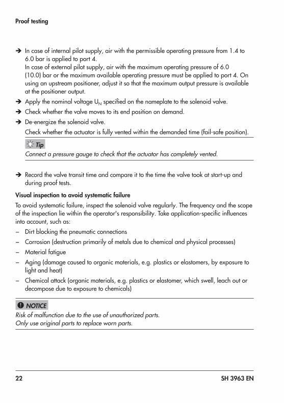
Î In case of internal pilot supply, air with the permissible operating pressure from 1.4 to 6.0 bar is applied to port 4. In case of external pilot supply, air with the maximum operating pressure of 6.0 (10.0) bar or the maximum available operating pressure must be applied to port 4. On using an upstream positioner, adjust it so that the maximum output pressure is available at the positioner output.
Î Apply the nominal voltage UN specified on the nameplate to the solenoid valve. Î Check whether the valve moves to its end position on demand. Î De-energize the solenoid valve.Check whether the actuator is fully vented within the demanded time (fail-safe position).
Connect a pressure gauge to check that the actuator has completely vented.
Î Record the valve transit time and compare it to the time the valve took at start-up and during proof tests.
Visual inspection to avoid systematic failureTo avoid systematic failure, inspect the solenoid valve regularly. The frequency and the scope of the inspection lie within the operator's responsibility. Take application-specific influences into account, such as: − Dirt blocking the pneumatic connections − Corrosion (destruction primarily of metals due to chemical and physical processes) − Material fatigue − Aging (damage caused to organic materials, e.g. plastics or elastomers, by exposure to
light and heat) − Chemical attack (organic materials, e.g. plastics or elastomer, which swell, leach out or
decompose due to exposure to chemicals)
Risk of malfunction due to the use of unauthorized parts.Only use original parts to replace worn parts.
Tip
NOTICE!

SH 3963 EN 23
Repairs
7 RepairsOnly perform the work on the solenoid valve described in u EB 3963.Only use the specified original mounting parts.
Fail-safe action impaired due to incorrect repair.Service and repair work must be performed by trained staff only.
Note

24 SH 3963 EN
Safety-relateddataandcertificates
8 Safety-relateddataandcertificatesThe Type 3963 Solenoid Valves are suitable for use in safety-instrumented systems accord-ing to IEC 61508. The devices have an HFT of 0 and can be used up to SIL 2 (single device, HFT = 0) and SIL 3 (redundant configuration, HFT = 1) according to IEC 61511.Verification is based on the certificate issued by TÜV Rheinland® V 60.09/14 rev. 01.
Useful lifetimeAccording to IEC 61508-2, section 7.4.9.5, a useful lifetime of eight to twelve years can be assumed. Other values can be used based on the user’s previous experience (prior use).
Safety-related data
λsafe, undetected 16 FIT 1)
λsafe, detected 0
λdangerous, undetected 2 FIT 1)
λdangerous, detected 0
PFDavg. with annual test 7.79 × 10⁻⁶
HFT (Hardware Fault Tolerance) 0
DC (Diagnostic Coverage) 0 %
Device type A
Operating mode Low Demand
Safe failure fraction (SFF) 90 %
MTBFtotal 6416 years
MTBFdangerous, undetected 64156 years
1) 1 FIT = 1 failure per 109 hours
Intended use − Mounting and operating instructions − Instrument air requirements
Safety-related assumptionsWhen the power supply or the supply pressure fail, the pneumatic booster discharges its out-put to the atmosphere, thus venting the mounted actuator.

SH 3963 EN 25
Safety-relateddataandcertificates
Requirements − Short mean time to repair compared to the average rate of demand. − Normal exposure to industrial environment and fluids is assumed.
The user is responsible for ensuring that the device is used as intended.

26 SH 3963 EN

SH 3963 EN 27

2019
-11-
22 ·
Engl
ish
SAMSON AKTIENGESELLSCHAFTWeismüllerstraße 3 · 60314 Frankfurt am Main, GermanyPhone: +49 69 4009-0 · Fax: +49 69 [email protected] · www.samson.de
SH 3963 EN