Safety Light CurtainSafety Light Curtain F3SG-R Series · workpieces pass or the position of a...
105
Safety Light Curtain S S S Sa a a af f f fe e e et t t t ty y y y L L L L Li i ig g g h h h h ht t t t t C C C Cu u u ur r rt ta ai i in n New standard, offering both robustness and reliability Global: Reliable safety solutions » » » F3SG-R Series Robust: Even in severe environments Compact: Easy installation ustness and reliability »
Transcript of Safety Light CurtainSafety Light Curtain F3SG-R Series · workpieces pass or the position of a...

Safety Light CurtainSSSSaaaaffffeeeetttttyyyyy LLLLLiiigggghhhhhttttt CCCCuuuurrrttaaiiinn
New standard, offering both robustness and reliability
G l o b a l : R e l i a b l e s a f e t y s o l u t i o n s
» »
»
F3SG-R Series
Robust: Even in severe environmentsC o m p a c t : E a s y i n s t a l l a t i o n
ustness and reliability
»

2
Next generation safety
Operating range0.3 to 10.0 m
Protective height190 to2510 mm
Operating range0.3 to 20.0 m
Protective height160 to2080 mm
Operating range0.3 to 10.0 m
Protective height190 to2510 mm
Operating range0.3 to 20.0 m
Protective height160 to2080 mm
Advance type suitable for flexible production line applications
Easy type ideal for simple On/Off detection applications
Advance Easy
NEW
F3SG-4RA -14Detection capability: Dia. 14 mm
F3SG-4RA -30Detection capability: Dia. 30 mm
F3SG-4RA- -25-01TSDetection capability: Dia. 25 mm
F3SG-4RE -14Detection capability: Dia. 14 mm
F3SG-4RE -30Detection capability: Dia. 30 mm

3
light curtain packed with powerful features, offering both robustness and reliability
Previously it took time to select the right safety light curtains for the conditions: physical conditions such as size and
operating range, ambient environments, and countries.
If just one single safety light curtain can be used in a variety of environments, the time required for selection, installa-
tion, and maintenance can be reduced.
Easy Selection & Design
In almost any environmentWaterproof and shock-resistant yet compact body. Conforms to major international standards including Chinese
standard GB 4585 to be used worldwide.
Ensuring safety in various production linesThe Muting function to automatically set a minimum muting zone according to workpiece height.
Can be used for a variety of production lines.
Complete safety measures by detecting presenceDistinguishes between small object passing and human entry by changing resolution and response time.
This maintains a high level of safety while minimizing unexpected machine downtime.
Easy Set-up
The Smartclick connectors and optical synchronization enable smooth set-up of machines.
Quick adjustment by checking beam alignment with the LED indicators and Configuration Tool SD Manager2.
More flexible layout by eliminating the need of synchronization wiring and using extension cables.
Operation
The sticker and error logs stored in the F3SG-R helps speed troubleshooting. Accumulated log data facilitates
systematic maintenance.
The DIP switches is used to change emission light intensity to prevent mutual interference with other sensors.
>> p4
>> p8
>> p10
Thinnest part 2.5 mm
35mm
35mm
Selection & Design
Set-up
F3SG-R Benefi t
Drastically reduced set-up time and wiring
Simple, two-step optical adjustment
Flexible installation
Stable Operation
Quick troubleshooting and predictive maintenance
Mutual interference prevention
Microsoft product screen shot(s) reprinted with permission from Microsoft Corporation.
The Bluetooth® word mark and logos are registered trademarks owned by Bluetooth SIG, Inc. Any use of such marks by Omron is under license.
Other company names and product names in this document are the trademarks or registered trademarks of their respective companies.

4
Easy Selection & Design
Robust and Compact | Robust housing |
All models are equipped with a robust housing that can be used in harsh conditions and withstand shocks caused by sudden human contact or a dropped tool. The scratch-resistant material is used for the optical surface to prevent unexpected machine stops.
Slim housing Protected with protection cover
Thinnest part 2.5 mm
35mm
35mm
The robust housing can be used in
harsh conditions and withstand shocks
caused by sudden human contact or
a dropped tool. The scratch-resistant
material is used for the optical sur-
face to prevent unexpected machine
stops.Cross-section is
Approx. 60%of previous model
In almost any environment | For global use |The F3SG-R is designed to be used in a variety of environments around the world, conforming to international sta
For global use
For harsh environments
Several types of safety light curtains with
different environmental resistance and
functionality were required to suit the in-
stallation environment. It took time to
select the right models.
Mixing several modelsPreviously…
Downsized
Workpiece
For harsh environments
NPN PNPGlGlGlGlGlG oobooboobalaaa Innnnnnnnnttttetetetetttetet rnnnnatatatioioioooionanananananananan lStStStStSSttaanaananandadadadd rdrdrdrdddrdddd
GB
ISOIEC
IP67IP67R
In almost any environment | For global use |The F3SG-R is designed to be used in a variety of environmeworld, conforming to international sta
For global use
Ro b u s t n e s s Allows use in a variety of environmentsP r o t e c t s i t s e l f a n d p r o d u c t i o n s i t e s
The housing structure is significantly improved to enhance resistance against shock and vibra-tion and to reduce the thickness of the thinnest part of the housing material from 3 mm to 2.5mm.
The optical surface can be protected from con-tact with workpieces by using the optional pro-tection cover together.
PNP or NPN can be selected with the DIP switch. The same cables are used.
IP67 protection allows use in environments that are subject to water.
The F3SG-R conforms to major interna-tional standards including Chinese GB standards
Advance
Advance Easy
Mixing several modelsPreviously…P i l
IP
7 se
I
67ere
P6rea
IPa
The newly designed high-power optical system provides the best-in-class* light transmission and operating range. This allows stable operation even in dusty or other environments where light transmission is reduced.* Based on OMRON investigation in December 2014.
* Compared to OMRON previous model in December 2014.
Reliable even in harsh environments Advance Easy
Operating range
Secured against torsion
High power
F3SG-RPrevious model
The risk of optical axis misalignment due to vibration or aging can be re-duced.
20m max.
5times more torsion resistant*
F3SG-R
F3SR
MS48
Advance Easy

5
Increasing both productivity and safety| Muting function |
The F3SG-R provides advanced Muting function that detects the zone where workpieces pass or the position of a machine or robot and disable beams of the detected part. This increases both safety and productivity. By adding the smart muting actuator, the F3SG-R provides stable operation even for the production lines where errors occur due to vibration caused by the passing workpiece.
Adjustment time reduced by 80%*| Smart muting actuator |The use of the dedicated actuator can sig-nificantly reduce the time required to adjust the sensor to detect workpieces even in un-stable conveying conditions
Since bypass processing to disable
the safety light curtain was per-
formed via the PLC, programming
before installation required time and
work. It also took a lot of time and
work to install and adjust many
muting sensors (sensors and reflec-
tors).
Many processes including programming
and adjustment were requiredPreviously…
0 10 20 30 40 50 60 70 80 90 100
Reduced by 80%
Prev
ious
m
odel
F3SG
-R
*Compared to the previous model
(Based on OMRON investigation in
September 2014)
e reduced by 80%*tuator |ted actuator can sig-me required to adjust orkpieces even in un-tions
odel
n in
F3SG
B1
ReflectorA2
Sensor A1
F3SG
The muting actuator detects the surface of a passing workpiece. Even if a workpiece moves due to vibration, muting is kept enabled until the workpiece has passed. This prevents unexpected machine stops.
The point detection muting sensor mistakenly disabled muting while a workpiece was passing, which led to unexpected machine stops.
N ew M u t i n g Fu n c t i o n a l i ty Increases both productivity and safetyE a s i l y d i s t i n g u i s h e s b e t w e e n w o r k e r s a n d o b j e c t s
Advance
Vibration
Opening
Automatically and flexibly detect even in unstable conveying conditions.
Photoelectric Sensor
Smart muting actuator
Advance
Installation Wiring Adjustment Troubleshooting Maintenance
otoelectric Sensor
Previously…
Smart muting actuatorme and
and adjust many
ng sensors (sensors and reflec-
tors).
B1
ReflectorA2
Sensor A1
ng actuator detects the surface of a passing workpiece. Even if a workpiece moves due to vibration, muting is kept enabled until the workpiece has passed. This prevents unexpectedmachine stops.
ally and flexibly etect even in unstable
conveying conditions.

6
Auto-configuration of muting zone| Dynamic Muting |
When workpieces with various heights are conveyed on the same line, partial muting is automatically performed based on the height of the workpiece. This advanced muting function can automatically perform normal detection at the zone where a workpiece does not pass.
Automatically minimizes muting zoneaccording to workpiece size
When the muting sensor detects that a
workpiece passes, all beams are muted. 1
2
Minimizing setting and detection errors | Configuration Tool SD Manager2 |
The function to log the muting sensor operating conditions of the F3SG-R visualizes the installation position and setting conditions of the sensor to achieve reliable configuration. The stop due to the muting error can be analyzed using the data stored in the F3SG-R. Quick identification of the cause can reduce unexpected machine downtime.
Visualized data makes adjustment
smooth!
The only beams interrupted by the workpiece are kept
muted and other beams are released from the muting
state three seconds after the workpiece pass through the
safety light curtain. Muting is disabled after the work-
piece has passed.
Monitors human entry into
the zone where a workpiece
does not pass.
Keeps the zone muted when
a workpiece passes.
onditions ition and
e reliable or can be-R. Quick
d machine
zed data djustment ooth!
Easy Selection & Design
P o w e r f u l Fe a t u r e s Prevent unexpected machine stopsE n s u r e s t a b l e o p e r a t i o n
Advance
Advance

7
Detecting both objects and workers | Reduced Resolution |
With the Reduced Resolution function that is used to change the number of interrupted beams (1 to 3 beams), the F3SG-R can detect human entry while workability is maintained. This makes easier to distinguish between objects and workers.
Preventing accidental stops due to insects | Response Time Adjustment |
This function is used to distinguish between an instant passing of a small object such as an insect and a human passing by changing the time to respond to the block of the beam. Accidental machine stops can be avoided.
Helps prevent workers from being trapped
Ensuring safe restart | Pre-reset |
The Pre-reset function prevents possible accidents and supports safe restart of machines. Even if an worker press the reset switch of the safety light curtain without noticing another worker near the robot, restart will not be executed unless certain conditions are met.
1 Press the pre-reset switch in
the hazardous zone (safety fence)
2 Get out of the hazardous zone
(safety fence)
3 Press the reset switch in the
control panel to restart the F3SG-R.
The machine is ready for restart.
The machine cannot be restarted until the pre-reset switch is pressed to restart the F3SG-R.
1
32
Keep the safety outputs ON even when
an object like a transport vehicle (with
the size of 1 to 3 beams) is present dis-
continuously.
Turn safety outputs OFF when an object
with the size over 3 beams, like an ankle,
Helps pre
Ensurin| Pre-res
The Pre-resupports sthe reset noticing anexecuted u
Advance
Advance
Advance
8
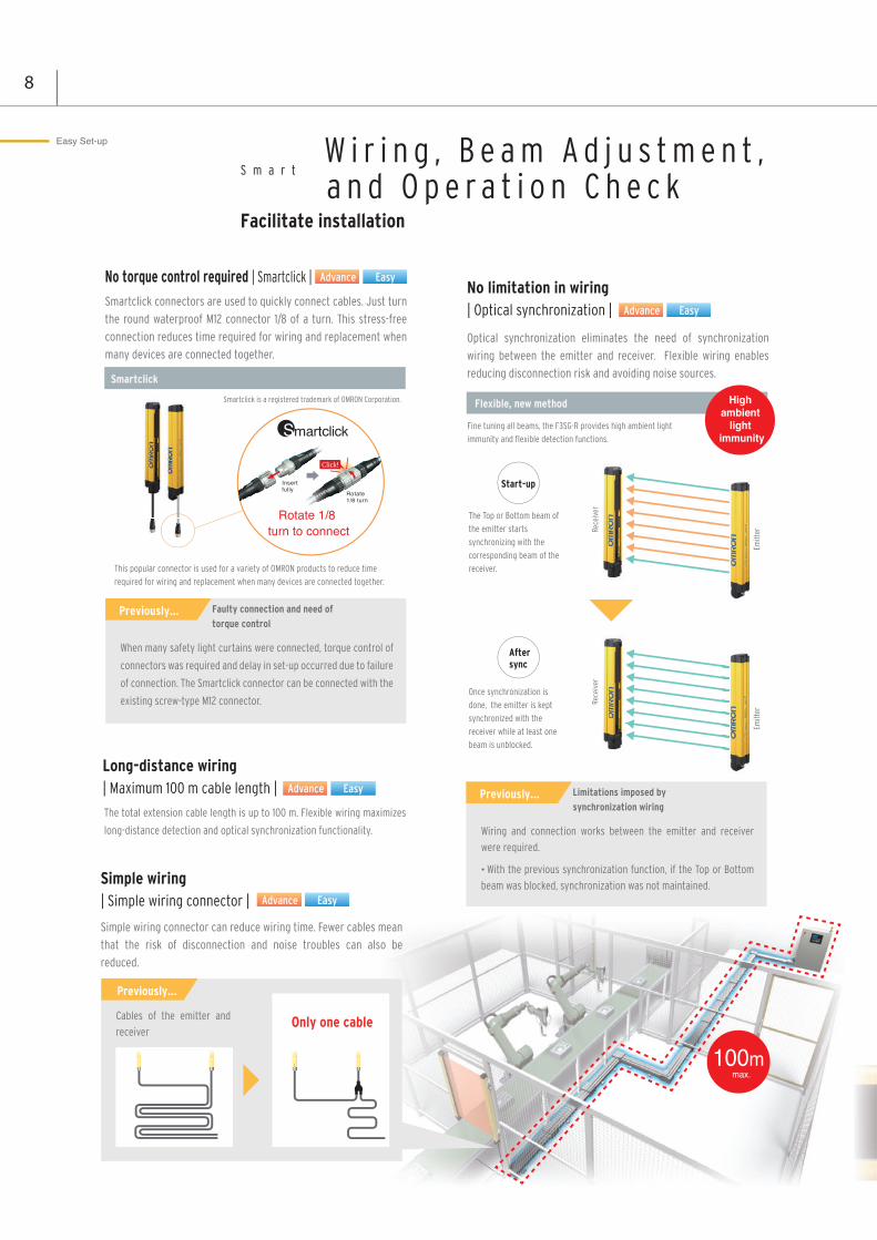
No torque control required | Smartclick |Smartclick connectors are used to quickly connect cables. Just turn the round waterproof M12 connector 1/8 of a turn. This stress-free connection reduces time required for wiring and replacement when many devices are connected together.
When many safety light curtains were connected, torque control of
connectors was required and delay in set-up occurred due to failure
of connection. The Smartclick connector can be connected with the
existing screw-type M12 connector.
Faulty connection and need of
torque controlPreviously…
Limitations imposed by
synchronization wiring Previously…
No limitation in wiring | Optical synchronization |
Optical synchronization eliminates the need of synchronization wiring between the emitter and receiver. Flexible wiring enables reducing disconnection risk and avoiding noise sources.
Flexible, new method
Smartclick
Start-up
Rece
iver
Rece
iver
Emitt
erEm
itter
The Top or Bottom beam of
the emitter starts
synchronizing with the
corresponding beam of the
receiver.
Once synchronization is
done, the emitter is kept
synchronized with the
receiver while at least one
beam is unblocked.
Rece
iver
After sync
This popular connector is used for a variety of OMRON products to reduce time
required for wiring and replacement when many devices are connected together.
Smartclick is a registered trademark of OMRON Corporation.
Advance Easy
Advance Easy
Wiring and connection works between the emitter and receiver were required.
With the previous synchronization function, if the Top or Bottom beam was blocked, synchronization was not maintained.
Insert fully
Rotate 1/8 turn
Click!
Rotate 1/8 turn to connect
Easy Set-up W i r i n g , B e a m A d j u s t m e n t , a n d O p e r a t i o n C h e c k
Facilitate installation
S m a r t
Long-distance wiring| Maximum 100 m cable length |
Fine tuning all beams, the F3SG-R provides high ambient light
immunity and flexible detection functions.
Simple wiring| Simple wiring connector |
Simple wiring connector can reduce wiring time. Fewer cables mean that the risk of disconnection and noise troubles can also be reduced.
Advance Easy
Advance Easy
High ambient
light immunity
Cables of the emitter and receiver
Only one cable
The total extension cable length is up to 100 m. Flexible wiring maximizes
long-distance detection and optical synchronization functionality.
Previously…
100m max.

9
Simple two steps | Beam adjustment |
The benefit of robust, torsion-resistant housing contributes to reduce the time required to install the safety light curtain.
Beam adjustment can be done easily by checking the TOP and BTM LED
indicators. The SD Manager 2 helps install the safety light curtain by showing
the incident light levels of each beam.
Adjustment is completed when the TOP, BTM, and STB LED indicators turn ON.
Finer adjustments can be made using the Configuration Tool SB Manager2.
Easy adjustment after mounting | Mounting bracket |Two types of mounting brackets are available.
Protective height No. of brackets included
Less than 1,280 mm
1,280 to 2,270 mm
2,350 mm or more
2 sets
3 sets
4 sets
TOP indicator turns ON when top end receives light.
BTM indicator turns ON when bottom end receives light.
1
2
TOP (top-beam-state indicator)
BTM (bottom-beam-state indicator)
1
2
Standard fixed bracket
The bracket is included in the F3SG-R.
Standard fixed bracket Standard adjustable bracket(sold separately)
After mounted on a safety fence, the F3SG-R
can be slid vertically to adjust. This means
this mounting bracket allows for a wider ad-
justment range than the existing top/bottom
mounting bracket.
In addition to vertical adjustment, the angle
can be adjusted up to ±15°.adjusted up to
±15°.
Advance Easy
Simple adjustment: Coarse adjustment positional alignment
Advance

10
For global operators| Multilingual troubleshooting |
Troubleshooting in eight languages is published on the website to find causes and solutions of errors that occur during operation. Operators across the world can check the error details in their local languages, which will help them minimize time to troubleshoot.
Reducing stops due to mutual interference| Operating Range Selection |When other sensors are installed near the F3SG-R, Operating Range Selection helps reduce mutual interference.
Troubleshooting Web
Quick troubleshooting | Data logging 1 |
The error logs stored in the F3SG-R can be obtained by connecting with a personal computer via the interface unit. The Configuration Tool SD Manager2 analyzes error logs to identify causes of errors and suggest solutions. This helps simplify troubleshooting.
Systematic maintenance based on trend management| Data logging 2 |
By using the Configuration Tool SD Manager2, the data of light intensity, power-ON time, and switching frequency of the F3SG-R can be collected regularly to predict when systematic and preventive maintenance is required.
Troubleshooting guide sticker
* English, Chinese, Italian, Korean,
French, German, Spanish, and Japanese
Mutual interference with the other sensor
near the F3SG-R can be reduced by changing
the mode from Long * to Short (7 m).
The mode of Operating Range Selection can be
selected with the DIP Switches* on the emitter.
Operating range
* The Interface Unit F39-GIF is required to connect with a personal computer.
Long20m
Short7m
*. Maximum operating range of 20 m for
hand/arm protection or 10 m for finger
protection
Advance Easy
Advance Easy
Advance
Advance
*. For the F3SG-RE, the mode can be selected by wiring.
Stable Operation
Troubleshoot ing and Predict ive MaintenanceEliminate machine downtime to ensure stable operation
Q u i c k

Easy-to-use safety sensor
Ideal for Simple On/Off Detection Applications
Only four wires are required for the minimum configuration, which is as
simple as wiring a photoelectric sensor. Simple connection with a safety
controller makes it easy to build a safety circuit. Commercially available M12
connector cables can be used for extension cables.
Simple wiring Fast response time of 5 ms
The Easy type that allows the distance between the light curtain and
hazard source to be reduced is best suited to use in a small machine.
F3SG-R Line-up
List of Feature
Feature F3SG-RA F3SG-REFactory default setting(Advance type)
PNP output
24 V Active
Auto Reset Mode
Disabled
Disabled
Safety output (Inverted signal output)
Standard Muting mode
Enabled
Disabled
Disabled
Disabled
Disabled
CodeA
Long mode
Standard mode
Disabled
type F3SG-RA type F3SG-REAdvance Easy
Advance type Easy type
Robust but slim housing and basic safety functions are inherited from the F3SG-R Advance type.Providing only simple safety functions, the Easy type helps save TCO (Total Cost of Ownership) by reducing errors that required a lot of time to identify the causes.
N E W Easy type
PNP/NPN Selection
External Test
Interlock
Pre-Reset
External Device Monitoring(EDM)
Auxiliary Output
Muting
Override
Fixed Blanking
Floating Blanking
Reduced Resolution
Warning Zone
Scan Code Selection
Operating Range Selection
Response Time Adjustment
Lamp
Designated Beam Output
Cascade Connection
Setting by DIP Switch Setting by Configuration Tool
More slim models
Cat. No. F074
For flexible zone detection
Cat. No. Z298
Safety Sensor
Line-upSafety Light Curtain F3SJ
Safety Laser Scanner
For small machinesFor flexible
production lines
Setting by Wiring
Red:Safety output infomation(Inverted signal output)Orange:Stable-state infomation (Inverted signal output)Green:Safety output infomation
Note: The F3SG-4RA□□□□-25-01TS provides only the monitoring functionality.

12
Safety Light Curtain Advance type
F3SG-RANew Standard of Safety Light Curtain,Offering Both Robustness and Reliability• Robust and compact• New muting function to increase both productivity and
safety• All models designed for global use. PNP/NPN selection by
DIP switch• Conforming to major international standards including
Chinese standard GB 4584 *
* The F3SG-4RA@@@@-25-01TS does not conform.
Ordering InformationMain UnitsSafety Light Curtain
Finger protection Hand and arm protection
Number of beams Protective height (mm) Model
15 160 F3SG-4RA0160-14
23 240 F3SG-4RA0240-14
31 320 F3SG-4RA0320-14
39 400 F3SG-4RA0400-14
47 480 F3SG-4RA0480-14
55 560 F3SG-4RA0560-14
63 640 F3SG-4RA0640-14
71 720 F3SG-4RA0720-14
79 800 F3SG-4RA0800-14
87 880 F3SG-4RA0880-14
95 960 F3SG-4RA0960-14
103 1,040 F3SG-4RA1040-14
111 1,120 F3SG-4RA1120-14
119 1,200 F3SG-4RA1200-14
127 1,280 F3SG-4RA1280-14
135 1,360 F3SG-4RA1360-14
143 1,440 F3SG-4RA1440-14
151 1,520 F3SG-4RA1520-14
159 1,600 F3SG-4RA1600-14
167 1,680 F3SG-4RA1680-14
175 1,760 F3SG-4RA1760-14
183 1,840 F3SG-4RA1840-14
191 1,920 F3SG-4RA1920-14
199 2,000 F3SG-4RA2000-14
207 2,080 F3SG-4RA2080-14
Number of beams Protective height (mm) Model
8 190 F3SG-4RA0190-30
12 270 F3SG-4RA0270-30
16 350 F3SG-4RA0350-30
20 430 F3SG-4RA0430-30
24 510 F3SG-4RA0510-30
28 590 F3SG-4RA0590-30
32 670 F3SG-4RA0670-30
36 750 F3SG-4RA0750-30
40 830 F3SG-4RA0830-30
44 910 F3SG-4RA0910-30
48 990 F3SG-4RA0990-30
52 1,070 F3SG-4RA1070-30
56 1,150 F3SG-4RA1150-30
60 1,230 F3SG-4RA1230-30
64 1,310 F3SG-4RA1310-30
68 1,390 F3SG-4RA1390-30
72 1,470 F3SG-4RA1470-30
76 1,550 F3SG-4RA1550-30
80 1,630 F3SG-4RA1630-30
84 1,710 F3SG-4RA1710-30
88 1,790 F3SG-4RA1790-30
92 1,870 F3SG-4RA1870-30
96 1,950 F3SG-4RA1950-30
100 2,030 F3SG-4RA2030-30
104 2,110 F3SG-4RA2110-30
108 2,190 F3SG-4RA2190-30
112 2,270 F3SG-4RA2270-30
116 2,350 F3SG-4RA2350-30
120 2,430 F3SG-4RA2430-30
124 2,510 F3SG-4RA2510-30

F3SG-RA
13
Hand protection
Accessories (Sold separately)Single-ended Connector CableFor F3SG-4RA@@@@-14/-4RA@@@@-30
Note: To extend the cable length to 20 m or more, add the F39-JG@B Double-end Connector Cable.Example: When using a cable of 30 m, connect the F39-JG10A Single-end Connector Cable with the F39-JG20B Double-end Connector Cable.
Single-ended Connector Cable (2 covers per set, one for emitter and one for receiver)For F3SG-4RA@@@@-25-01TS
Note: To extend the cable length to more than 20 m, add the F39-JD@B Double-ended Connector Cable.Example: When using a cable of 30 m, connect the F39-JD10A Single-ended Connector Cable with the F39-JD20B Double-ended Connector Cable.
Number of beams
Protective height (mm) Model
8 185 F3SG-4RA0185-25-01TS
12 265 F3SG-4RA0265-25-01TS
16 345 F3SG-4RA0345-25-01TS
20 425 F3SG-4RA0425-25-01TS
24 505 F3SG-4RA0505-25-01TS
28 585 F3SG-4RA0585-25-01TS
32 665 F3SG-4RA0665-25-01TS
36 745 F3SG-4RA0745-25-01TS
40 825 F3SG-4RA0825-25-01TS
44 905 F3SG-4RA0905-25-01TS
48 985 F3SG-4RA0985-25-01TS
52 1065 F3SG-4RA1065-25-01TS
56 1145 F3SG-4RA1145-25-01TS
60 1225 F3SG-4RA1225-25-01TS
64 1305 F3SG-4RA1305-25-01TS
72 1465 F3SG-4RA1465-25-01TS
80 1625 F3SG-4RA1625-25-01TS
88 1785 F3SG-4RA1785-25-01TS
96 1945 F3SG-4RA1945-25-01TS
Appearance Type Cable length Specifications Model
For emitterM12 connector (5-pin), 5 wiresColor: Gray
3 m F39-JG3A-L7 m F39-JG7A-L
10 m F39-JG10A-L15 m F39-JG15A-L20 m F39-JG20A-L
For receiverM12 connector (8-pin), 8 wiresColor: Black
3 m F39-JG3A-D
7 m F39-JG7A-D
10 m F39-JG10A-D
15 m F39-JG15A-D
20 m F39-JG20A-D
Appearance Cable length Specifications Model
3 m F39-JD3A
7 m F39-JD7A
10 m F39-JD10A
15 m F39-JD15A
20 m F39-JD20A
53
21
4
Female
12345
+24 VDCTEST0 VDCNot usedNot used
BrownBlackBlueWhiteYellow
5
843
2176
Female
2
7
56
1+24 VDC
0 VDC
OSSD 1OSSD 2
RESET Brown
Blue
BlackWhite
Yellow
8 AUX Red
3 MUTE A Gray4 MUTE B Pink
Connected to Power Cable or Double-Ended Cable
5
843
2176
Female
2
7
56
1+24 VDC
0 VDC
Not usedNot used
Not usedBrown
Blue
GrayPink
White
8 Not used Red
3 TEST Black4 Not used Yellow
Connected to Power Cable or Double-Ended Cable
5
843
2176
Female
2
7
56
1+24 VDC
0 VDC
Not usedNot used
OSSD 2Brown
Blue
GrayPink
White
8 EDM Red
3 OSSD 1 Black4 AUX Yellow
For emitter M12 connector (8-pin), Color: Gray
For receiver M12 connector (8-pin), Color: Gray

F3SG-RA
14
Double-ended Connector CableFor cable extension and simple wiring
For F3SG-4RA@@@@-14/-4RA@@@@-30
Note: To extend the cable length to more than 20 m, use the F39-JG@B Double-ended Connector Cables in combination.Example: When using a cable of 30 m, connect the F39-JG10B Double-ended Connector Cable with the F39-JG20B Double-ended Connector Cable.To extend the cable length under series connection, use F39-JGR2W and F39-JG@B in combination. Also, the cable length 10 to 20m cannot be used.
Doble-ended Connector Cable (2 covers per set, one for emitter and one for receiver)For F3SG-4RA@@@@-25-01TS
Note: To extend the cable length to more than 20 m, use the F39-JD@B Double-ended Connector Cables in combination.Example: When using a cable of 30 m, connect the F39-JD10B Double-ended Connector Cable with the F39-JD20B Double-ended Connector Cable.To extend the cable length under series connection, use F39-JGR2WTS and F39-JD@B in combination. Also, the cable length 10 to 20m cannot be used.
Appearance Type Cable length Specifications Model
For emitterM12 connector (5-pin) on both endsColor: Gray
0.5 m F39-JGR5B-L1 m F39-JG1B-L3 m F39-JG3B-L5 m F39-JG5B-L7 m F39-JG7B-L
10 m F39-JG10B-L15 m F39-JG15B-L20 m F39-JG20B-L
For receiverM12 connector (8-pin) on both endsColor: Black
0.5 m F39-JGR5B-D1 m F39-JG1B-D3 m F39-JG3B-D5 m F39-JG5B-D7 m F39-JG7B-D
10 m F39-JG10B-D15 m F39-JG15B-D20 m F39-JG20B-D
Appearance Cable length Specifications Model
0.5 m F39-JDR5B
1 m F39-JD1B
3 m F39-JD3B
5 m F39-JD5B
7 m F39-JD7B
10 m F39-JD10B
15 m F39-JD15B
20 m F39-JD20B
BrownBlueBlackWhiteYellow
13245
53
21
4
BrownBlueBlackWhiteYellow
13245
Female
54
12
3
Male
Connected to Power Cable or Double-Ended Cable
Connected to Single-Ended Cable, orDouble-Ended cable
BrownBlueBlackWhiteYellowRedGrayPink
BlueBlackWhiteYellowRedGrayPink
27561834
Brown
5
84
321
7
65
86
712
3
4
27561834
Connected to Power Cable or Double-Ended Cable
Connected to Single-Ended Cable, orDouble-Ended cable
Female Male
Emitter Cable is gray F39-JG@B-L(Gray) F39-JG@A-L(Gray)
Receiver Cable is black F39-JG@B-D(Black) F39-JG@A-D(Black)
Double-Ended CableF39-JG@B
Single-Ended CableF39-JG@A
<Connection example>
BrownBlueGrayPinkWhiteRedBlackYellow
BlueGrayPinkWhiteRedBlackYellow
27561834
Brown
5
84
321
7
65
86
712
3
4
27561834
Female Male
BrownBlueGrayPinkWhiteRedBlackYellow
BlueGrayPinkWhiteRedBlackYellow
27561834
Brown
5
84
321
7
65
86
712
3
4
27561834
Connected to Power Cable or Double-Ended Cable
Connected to Single-Ended Cable, orDouble-Ended cable
Female Male
For emitter M12 connector (8-pin), Color: Gray
For receiver M12 connector (8-pin), Color: Black
Emitter
Receiver
Cable is grey
Cable is black
Cable with connectors on both endsF39-JD�B
Cable with connector on one endF39-JD�A
F39-JD�B-L (Grey) F39-JD�A-L (Grey)
F39-JD�B-D (Black) F39-JD�A-D (Black)
<Connection example>

F3SG-RA
15
Y-Joint Plug/Socket Connector for F3SG-4RA@@@@-14/-4RA@@@@-30
Cascading Cable (Two cables per set, for emitter and receiver)
For F3SG-4RA@@@@-14/-4RA@@@@-30
Cascading Cable (Two cables per set, for emitter and receiver)
For F3SG-4RA@@@@-25-01TS
Appearance Type Cable length Specifications Model
M12 connectors.Used for reducedwiring.
0.5 m F39-GCNY2
Appearance Type Cable length Specifications Model
Emitter cable:Cap (5-pin), M12 connector (5-pin)Receiver cable:Cap (8-pin), M12 connector (8-pin)
0.2 m F39-JGR2W
Appearance Type Cable length Specifications Model
Cap (8-pin), M12connector (8-pin) 0.2 m F39-JGR2WTS
F3SG-RAEmitter
Double-ended CableF39-JG@B-L(Gray)
Single-ended ConnectorCableF39-JG@A-D(Black)
Y-Joint Plug/Socket Connector for AdvanceF39-GCNY2
F3SG-RAReceiver
Secondary sensor 1 (Emitter)
Secondary sensor 1 (Receiver)
Primary sensor (Emitter)
Primary sensor (Receiver)
Cascading CableF39-JGR2W
CableF39-JG@@@-L
CableF39-JG@@@-D
Secondary sensor 1 (Emitter)
Secondary sensor 1 (Receiver)
Primary sensor (Emitter)
Primary sensor (Receiver)
Cascading CableF39-JGR2WTS
CableF39-JD@A-D
CableF39-JD@A-L

F3SG-RA
16
Sensor Mounting Brackets
*1 Two brackets per set[for F3SG-4RA@@@@-14]- Protective height of 0160 to 1200: 2 sets, Protective height of 1280 to 2080: 3 sets[for F3SG-4RA@@@@-30]- Protective height of 0190 to 1230: 2 sets, Protective height of 1310 to 2270: 3 sets, Protective height of 2350 to 2510: 4 sets
*2 Top/Bottom Adjustable Bracket cannot be used with the Standard Fixed Bracket. Use with the Standard Adjustable Bracket. Using Top/Bottom Adjustable Brackets with Standard Adjustable BracketsF3SG-4RA@@@@-14: Protective height of 1120 to 1920: 1 set of Top/Bottom Adjustable Brackets and 1 set of Standard Adjustable Brackets
Protective height of 2000 to 2080: 1 set of Top/Bottom Adjustable Brackets and 2 sets of Standard Adjustable BracketsProtective height of 1040 or lower: Standard Adjustable Brackets cannot be used.
F3SG-4RA@@@@-30: Protective height of 1150 to 1950: 1 set of Top/Bottom Adjustable Brackets and 1 set of Standard Adjustable BracketsProtective height of 2030 to 2510: 1 set of Top/Bottom Adjustable Brackets and 2 sets of Standard Adjustable BracketsProtective height of 1070 or lower: Standard Adjustable Brackets cannot be used.
F3SG-4RA@@@@-25-01TS: Protective height of 1145 to 1945: 1 set of Top/Bottom Adjustable Brackets and 2 sets of Standard Adjustable BracketsProtective height of 1065 or lower: Standard Adjustable Brackets cannot be used.
*3 Not included in the F3SG-4RA@@@@-25-01TS product package. Purchase if required.
Interface units and configuration tool SD Manager 2
Lamp
Appearance Specification Application Model
Standard Fixed Bracket *3
Bracket to mount the F3SG-R.Side mounting and backside mounting possible.(Included in the F3SG-R product package. See *1 below for the number of included brackets.)
F39-LGF
Standard Adjustable Bracket
Bracket to mount the F3SG-R.Beam alignment after mounting possible.The angle adjustment range is ±15°.Side mounting and backside mounting possible.(Sold separately. See *1 below for the number of required brackets.)
F39-LGA
Top/Bottom Adjustable Bracket *2
Bracket to mount the F3SG-R. Use this bracket at the top and bottom positions of the F3SG-R. Beam alignment after mounting possible. The angle adjustment range is ±22.5°.Side mounting and backside mounting possible.(Sold separately. 4 brackets per set.)
F39-LGTB
Top/Bottom Adjustable Bracket *2(For user-made mounting part)
Top/Bottom Adjustable Bracket without a bracket to mount to the wall. Use the user's own wall mounting part to suit the machine. (Sold separately. 4 brackets per set.)
F39-LGTB-1
Appearance Type Specifications Model
SD Manager2
The Configuration Tool SD Manager 2 is available to download from our website at http://www.ia.omron.com/f3sg-r_tool.
To change the settings of the F3SG-RA using SD Manager 2, it is necessary to set the receiver's two DIP switches No. 8 to ON.
−
Interface Unit F39-GIF interface unit to connect the F3SG-RA receiver to a USB port of the PC F39-GIF
Bluetooth Communication Unit
F39-BT bluetooth unit to enable bluetooth on the F3SG-RA F39-BT
Appearance Type Specifications Model
Lamp The lamp unit can be connected to a receiver and turned ON based on the operation of F3SG-RA.
The lamp can indicate red, orange, and green colors, to which three different states can be assigned.
F39-LP
Lamp and Bluetooth Communication Unit F39-BTLP

F3SG-RA
17
End Cap
Laser Pointer for F3SG-R
Spatter Protection Cover(Two covers per set, for emitter and receiver)Spatter Protection Covers include mounting brackets. For Safety Light Curtain models of the protective height of 2,000 mm or longer, use two Spatter Protection Covers of different lengths.
Note: The operating range of the Safety Light Curtain attached with the product is 10% shorter than the rating.
Test Rod
Appearance Specifications Model
Housing color: BlackFor both emitter and receiver(Attached to the F3SG-R. The End Cap can be purchased if lost.)
F39-CNM
Appearance Specifications Model
The laser pointer is attached on the optical surface of the F3SG-R to help coarse adjustment of beams. F39-PTG
AppearanceSafety Light Curtain Model
ModelFinger protection Hand protection Hand and arm protection
F3SG-@RA0160-14 F3SG-4RA0185-25-01TS F3SG-@RA0190-30 F39-HGA0200
F3SG-@RA0240-14 F3SG-4RA0265-25-01TS F3SG-@RA0270-30 F39-HGA0280
F3SG-@RA0320-14 F3SG-4RA0345-25-01TS F3SG-@RA0350-30 F39-HGA0360
F3SG-@RA0400-14 F3SG-4RA0425-25-01TS F3SG-@RA0430-30 F39-HGA0440
F3SG-@RA0480-14 F3SG-4RA0505-25-01TS F3SG-@RA0510-30 F39-HGA0520
F3SG-@RA0560-14 F3SG-4RA0585-25-01TS F3SG-@RA0590-30 F39-HGA0600
F3SG-@RA0640-14 F3SG-4RA0665-25-01TS F3SG-@RA0670-30 F39-HGA0680
F3SG-@RA0720-14 F3SG-4RA0745-25-01TS F3SG-@RA0750-30 F39-HGA0760
F3SG-@RA0800-14 F3SG-4RA0825-25-01TS F3SG-@RA0830-30 F39-HGA0840
F3SG-@RA0880-14 F3SG-4RA0905-25-01TS F3SG-@RA0910-30 F39-HGA0920
F3SG-@RA0960-14 F3SG-4RA0985-25-01TS F3SG-@RA0990-30 F39-HGA1000
F3SG-@RA1040-14 F3SG-4RA1065-25-01TS F3SG-@RA1070-30 F39-HGA1080
F3SG-@RA1120-14 F3SG-4RA1145-25-01TS F3SG-@RA1150-30 F39-HGA1160
F3SG-@RA1200-14 F3SG-4RA1225-25-01TS F3SG-@RA1230-30 F39-HGA1240
F3SG-@RA1280-14 F3SG-4RA1305-25-01TS F3SG-@RA1310-30 F39-HGA1320
F3SG-@RA1360-14 − F3SG-@RA1390-30 F39-HGA1400
F3SG-@RA1440-14 F3SG-4RA1465-25-01TS F3SG-@RA1470-30 F39-HGA1480
F3SG-@RA1520-14 − F3SG-@RA1550-30 F39-HGA1560
F3SG-@RA1600-14 F3SG-4RA1625-25-01TS F3SG-@RA1630-30 F39-HGA1640
F3SG-@RA1680-14 − F3SG-@RA1710-30 F39-HGA1720
F3SG-@RA1760-14 F3SG-4RA1785-25-01TS F3SG-@RA1790-30 F39-HGA1800
F3SG-@RA1840-14 − F3SG-@RA1870-30 F39-HGA1880
F3SG-@RA1920-14 F3SG-4RA1945-25-01TS F3SG-@RA1950-30 F39-HGA1960
F3SG-@RA2000-14 − F3SG-@RA2030-30F39-HGA1480
F39-HGA0550
F3SG-@RA2080-14 − F3SG-@RA2110-30F39-HGA1560
F39-HGA0550
− − F3SG-@RA2190-30F39-HGA1640
F39-HGA0550
− − F3SG-@RA2270-30F39-HGA1720
F39-HGA0550
− − F3SG-@RA2350-30F39-HGA1800
F39-HGA0550
− − F3SG-@RA2430-30F39-HGA1880
F39-HGA0550
− − F3SG-@RA2510-30F39-HGA1960
F39-HGA0550
Diameter Model14 mm dia. F39-TRD1425 mm dia. F39-TRD2530 mm dia. F39-TRD30
F3SG-RA
18
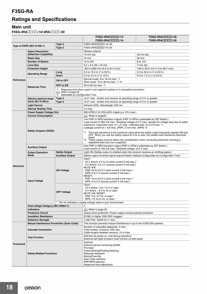
Ratings and SpecificationsMain unitF3SG-4RA@@@@-14/-4RA@@@@-30
F3SG-4RA -14F3SG-2RA -14
F3SG-4RA -30F3SG-2RA -30
Type of ESPE (IEC 61496-1)Type 4 F3SG-4RA -14/-30Type 2 F3SG-2RA -14/-30
Performance
Object Resolution(Detection Capability)
Opaque objects14-mm dia. 30-mm dia.
Beam Gap 10 mm 20 mmNumber of Beams 15 to 207 8 to 124Lens Size 5.2 × 3.4 (W × H) mm 7-mm dia.Protective Height 160 to 2080 mm (6.3 to 81.9 inch) 190 to 2510 mm (7.3 to 98.7 inch)
Operating RangeLong 0.3 to 10.0 m (1 to 32 ft.) 0.3 to 20.0 m (1 to 65 ft.)Short 0.3 to 3.0 m (1 to 10 ft.) 0.3 to 7.0 m (1 to 23 ft.)
Response Time
ON to OFF Normal mode: 8 to 18 ms max. *1Slow mode: 16 to 36 ms max. *1 *2
OFF to ON 40 to 90 ms max. *1
*1 Response time when used in one segment system or in cascaded connection. Refer to page 22.
*2 Selectable by Configuration Tool.
Effective Aperture Angle (EAA) (IEC 61496-2)
Type 4 ±2.5° max., emitter and receiver at operating range of 3 m or greaterType 2 ±5.0° max., emitter and receiver at operating range of 3 m or greater
Light Source Infrared LEDs, Wavelength: 870 nmStartup Waiting Time 2 s max.
Electrical
Power Supply Voltage (Vs) SELV/PELV 24 VDC±20% (ripple p-p 10% max.)Current Consumption Refer to page22 .
Safety Outputs (OSSD)
Two PNP or NPN transistor outputs (PNP or NPN is selectable by DIP Switch.)Load current of 300 mA max., Residual voltage of 2 V max. (except for voltage drop due to cable extension), Capacitive load of 1 μF max., Inductive load of 2.2 H max. *1Leakage current of 1 mA max. (PNP), 2 mA max. (NPN) *2
*1 The load inductance is the maximum value when the safety output frequently repeats ON and OFF. When you use the safety output at 4 Hz or less, the usable load inductance becomes larger.
*2 These values must be taken into consideration when connecting elements including a capacitive load such as a capacitor.
Auxiliary Output One PNP or NPN transistor output (PNP or NPN is selectable by DIP Switch.)Load current of 100 mA max., Residual voltage of 2 V max .
Output Operation Mode
Safety Output Light-ON (Safety output is enabled when the receiver receives an emitting signal.)Auxiliary Output Safety output (Inverted signal output:Enable) (default) (Cofigurable by Configuration Tool)
Input Voltage
ON Voltage
TEST: 24 V Active: 9 V to Vs (sink current 3 mA max.) *0 V Active: 0 to 3 V (source current 3 mA max.)
MUTE A/B:PNP: Vs to Vs-3 V (sink current 3 mA max.) *NPN: 0 to 3 V (source current 3 mA max.)
RESET:PNP: Vs to Vs-3 V (sink current 5 mA max.) *NPN: 0 to 3 V (source current 5 mA max.)
OFF Voltage
TEST: 24 V Active : 0 to 1.5 V or open0 V Active : 9 V to Vs or open
MUTE A/B, RESET:PNP: 0 to 1/2 Vs, or open *NPN: 1/2 Vs to Vs, or open *
* The Vs indicates a supply voltage value in your environment.Overvoltage Category (IEC 60664-1) IIIndicators Refer to page 25.Protective Circuit Output short protection, Power supply reverse polarity protectionInsulation Resistance 20 MΩ or higher (500 VDC megger)Dielectric Strength 1,000 VAC, 50/60 Hz (1 min)
Functional
Mutual Interference Prevention (Scan Code) This function prevents mutual interference in up to two F3SG-RA systems.
Cascade ConnectionNumber of cascaded segments: 3 max.Total number of beams: 255 max.Cable lengths between sensors: 10 m max.
Test Function Self-test (at power-on, and during operation)External test (light emission stop function by test input)
Safety-Related Functions
InterlockExternal device monitoring (EDM)Pre-resetFixed blanking/Floating blankingReduced resolutionMuting/OverrideScan code selectionPNP/NPN selectionResponse time adjustment

F3SG-RA
19
Environ-mental
Ambient TemperatureOperating -10 to 55°C (14 to 131°F) (non-icing)Storage -25 to 70°C (-13 to 158°F)
Ambient HumidityOperating 35% to 85% (non-condensing)Storage 35% to 95%
Ambient Illuminance Incandescent lamp: 3,000 Ix max. on receiver surfaceSunlight: 10,000 Ix max. on receiver surface
Degree of Protection (IEC 60529) IP65 and IP67Vibration Resistance (IEC 61496-1) 10 to 55 Hz, Multiple amplitude of 0.7 mm, 20 sweeps for all 3 axesShock Resistance (IEC 61496-1) 100 m/s2, 1000 shocks for all 3 axesPollution Degree (IEC 60664-1) Pollution Degree 3
Connec-tions
Power cable
Type of Connection M12 connectors: 5-pin emitter and 8-pin receiver, IP67 rated when mated, Cables prewired to the sensorsNumber of Wires Emitter: 5, Receiver: 8Cable Length 0.3 mCable Diameter 6 mmMinimum Bending Radius R5 mm
Cascading cable
Type of Connection M12 connectors: 5-pin emitter and 8-pin receiver, IP67 rated when matedNumber of Wires Emitter: 5, Receiver: 8Cable Length 0.2 mCable Diameter 6 mmMinimum Bending Radius R5 mm
Extension cable- Single-ended cable- Double-ended cable
Type of Connection M12 connectors: 5-pin emitter and 8-pin receiver, IP67 rated when matedNumber of Wires Emitter: 5, Receiver: 8Cable Length Refer to page 13.Cable Diameter 6.6 mmMinimum Bending Radius R36 mm
Extension of Power Cable 100 m max.
Material
Material
Housing: AluminumCap: PBTFront window: PMMACable: Oil resistant PVCMounting Bracket: ZDC2FE plate: SUS
Weight (packaged) Refer to page22 .
Included Accessories
Safety Precautions, Quick Installation Manual, Standard Fixed Bracket*, Troubleshooting Guide Sticker, Warning Zone Label* The quantity of Standard Fixed Brackets included varies depending on the protective height.[F3SG- RA -14]- Protective height of 0160 to 1200: 2 sets- Protective height of 1280 to 2080: 3 sets[F3SG- RA -30]- Protective height of 0190 to 1230: 2 sets- Protective height of 1310 to 2270: 3 sets- Protective height of 2350 to 2510: 4 sets
Conformity
Conforming standards Refer to page 24.
Type of ESPE (IEC 61496-1) Type 4
Performance Level (PL)/Safety category
Type 4 PL e/Category 4 (EN ISO 13849-1:2008)Type 2 PL c/Category 2 (EN ISO 13849-1:2008)
PFHd 1.1 × 10⁻⁸ (IEC 61508) Proof test interval TM Every 20 years (IEC 61508)SFF 99% (IEC 61508)HFT 1 (IEC 61508)Classification Type B (IEC 61508-2)
F3SG-4RA -14F3SG-2RA -14
F3SG-4RA -30F3SG-2RA -30

F3SG-RA
20
F3SG-4RA@@@@-25-01TSF3SG-4RA -25-01TS
Type of ESPE (IEC 61496-1) Type 4 F3SG-4RA -25-01TS
Performance
Object Resolution(Detection Capability)
Opaque objects25-mm dia.
Beam Gap 20 mmNumber of Beams 8 to 96Lens Size 6.0×5.0 (W×H) mmProtective Height 185 to 1945 mm (7.3 to 76.6 inch)
Operating RangeLong 0.3 to 17.0 m (1 to 56 ft.)Short 0.3 to 5.0 m (1 to 16 ft.)
Response Time
ON to OFF 8 to 13 ms *1OFF to ON 40 to 65ms *1*1 Response time when used in one segment system or in cascaded connection.
Refer to page 23.Effective Aperture Angle (EAA) (IEC 61496-2) Type 4 ±2.5° max., emitter and receiver at operating range of 3 m or greater
Light Source Infrared LEDs, Wavelength: 870 nmStartup Waiting Time 2 s max.
Electrical
Power Supply Voltage (Vs) SELV/PELV 24 VDC±20% (ripple p-p 10% max.)Current Consumption Refer to page 23 .
Safety Outputs (OSSD)
Two PNP or NPN transistor outputs (PNP or NPN is selectable by DIP Switch.)Load current of 300 mA max., Residual voltage of 2 V max. (except for voltage drop due to cable extension), Capacitive load of 1 μF max., Inductive load of 2.2 H max. *1Leakage current of 1 mA max. (PNP), 2 mA max. (NPN) *2
*1.*The load inductance is the maximum value when the safety output frequently repeats ON andOFF. When you use the safety output at 4 Hz or less, the usable load inductance becomes larger.
*2.*These values must be taken into consideration when connecting elements including acapacitive load such as a capacitor.
Auxiliary Output One PNP or NPN transistor output (Safety Output and homopolarity)Load current of 100 mA max., Residual voltage of 2 V max .
Output Operation Mode
Safety Output Light-ON (Safety output is enabled when the receiver receives an emitting signal.)Auxiliary Output Reverse output of safety output
Input Voltage
External device monitoring input (Lockout reset input)
PNPON voltage: Vs-3 V to Vs (short circuit current: approx. 6.5 mA) * OFF voltage: 0 V to 1/2 Vs, or open (short circuit current: approx. 8.0 mA) *
NPNON voltage: 0 V to 3 V (short circuit current: approx. 8.0 mA) *OFF voltage: 1/2 Vs to Vs, or open (short circuit current: approx. 6.5 mA) *
Test input
TEST:24 V inactive settingON voltage: 0 V to 1.5 V or open (short circuit current: approx. 2.0 mA)OFF voltage: 9 V to Vs (short circuit current: approx. 2.5 mA) *
0 V inactive settingON voltage: 9 V to Vs or open (short circuit current: approx. 2.5 mA)OFF voltage: 0 V to 3 V (short circuit current: approx. 2.0 mA)
* The Vs indicates a supply voltage value in your environment.Overvoltage Category (IEC 60664-1) IIIndicators Refer to page25 .Protective Circuit Output short protection, Power supply reverse polarity protectionInsulation Resistance 20 MΩ or higher (500 VDC megger)Dielectric Strength 1,000 VAC, 50/60 Hz (1 min)
Functional
Mutual Interference Prevention (Scan Code) This function prevents mutual interference in up to two F3SG-RA systems.
Cascade ConnectionNumber of cascaded segments: 3 max.Total number of beams: 255 max.Cable length between sensors: 10 m max.
Test Function Self-test (at power-on, and during operation)External test (light emission stop function by test input)
Safety-Related Functions External device monitoring (EDM)Scan code selectionPNP/NPN selection
Environ-mental
Ambient TemperatureOperating -10 to 55°C (14 to 131°F) (non-icing)Storage -25 to 70°C (-13 to 158°F)
Ambient HumidityOperating 35% to 85% (non-condensing)Storage 35% to 95%
Ambient Illuminance Incandescent lamp: 3,000 Ix max. on receiver surfaceSunlight: 10,000 Ix max. on receiver surface
Degree of Protection(IEC 60529) IP65 and IP67
Vibration Resistance(IEC 61496-1) 10 to 55 Hz, Multiple amplitude of 0.7 mm, 20 sweeps for all 3 axes
Shock Resistance(IEC 61496-1) 100 m/s2, 1000 shocks for all 3 axes
Pollution Degree(IEC 60664-1) Pollution Degree 3

F3SG-RA
21
Bluetooth Communication Unit
* It depends on use environment conditions.
Connec-tions
Power cable
Type of Connection M12 connectors: 8-pin emitter and receiver, IP67 rated when mated,Cables prewired to the sensors
Number of Wires On emitter: 5-wire, On receiver: 8-wireCable Length 0.3 mCable Diameter 6 mmMinimum Bending Radius R5 mm
Cascading cable
Type of Connection M12 connectors: 8-pin emitter and receiver, IP67 rated when matedNumber of Wires On emitter: 5-wire, On receiver: 8-wireCable Length 0.2 mCable Diameter 6 mmMinimum Bending Radius R5 mm
Extension cable- Single-ended cable- Double-ended cable
Type of Connection M12 connectors: 8-pin emitter and receiver, IP67 rated when matedNumber of Wires On emitter and receiver: 8-wireCable Length Refer to page 13.Cable Diameter 6.6 mmMinimum Bending Radius R36 mm
Extension of Power Cable 100 m max.(Emitter/Receiver)
MaterialMaterial
Housing: AluminumCap: PBTFront window: PMMACable: Oil resistant PVCFE plate: SUS
Weight (packaged) Refer to page 23 .Included Accessories Safety Precautions, Quick Installation Manual, Troubleshooting Guide Sticker,
Conformity
Conforming standards Refer to page 24 .Performance Level (PL)/Safety category Type 4
PFHd 1.1 × 10⁻⁸ (IEC 61508) Proof test interval TM Every 20 years (IEC 61508)SFF 99% (IEC 61508)HFT 1 (IEC 61508)Classification Type B (IEC 61508-2)
Communication System Bluetooth Version 3.0Communication Profile SPP (Serial Port Profile)Transmission Distance Approx. 10 m max. (Output power: Class 2) *
F3SG-4RA -25-01TS

F3SG-RA
22
List of Models/Response Time/Current Consumption/WeightF3SG-4RA -14/F3SG-2RA -14
F3SG-4RA -30/F3SG-2RA -30
Model Number of Beams
Protective Height[mm]
Response Time [ms] Current Consumption [mA]
Weight[kg]*2ON →
OFF*1
OFF(Synchronized)
→ ON
OFF (Not synchronized)
→ ONEmitter Receiver
F3SG-4RA0160-14 F3SG-2RA0160-14 15 160 8 40 140 40 75 1.8F3SG-4RA0240-14 F3SG-2RA0240-14 23 240 8 40 140 45 75 2.0F3SG-4RA0320-14 F3SG-2RA0320-14 31 320 8 40 140 55 75 2.2F3SG-4RA0400-14 F3SG-2RA0400-14 39 400 8 40 140 60 80 2.7F3SG-4RA0480-14 F3SG-2RA0480-14 47 480 13 65 165 50 80 2.9F3SG-4RA0560-14 F3SG-2RA0560-14 55 560 13 65 165 55 80 3.1F3SG-4RA0640-14 F3SG-2RA0640-14 63 640 13 65 165 60 85 3.3F3SG-4RA0720-14 F3SG-2RA0720-14 71 720 13 65 165 65 85 3.9F3SG-4RA0800-14 F3SG-2RA0800-14 79 800 13 65 165 65 90 4.1F3SG-4RA0880-14 F3SG-2RA0880-14 87 880 13 65 165 70 90 4.3F3SG-4RA0960-14 F3SG-2RA0960-14 95 960 13 65 165 75 90 4.5F3SG-4RA1040-14 F3SG-2RA1040-14 103 1040 13 65 165 80 95 4.7F3SG-4RA1120-14 F3SG-2RA1120-14 111 1120 13 65 165 85 95 4.8F3SG-4RA1200-14 F3SG-2RA1200-14 119 1200 13 65 165 90 100 5.0F3SG-4RA1280-14 F3SG-2RA1280-14 127 1280 13 65 165 95 100 5.2F3SG-4RA1360-14 F3SG-2RA1360-14 135 1360 13 65 165 95 105 5.6F3SG-4RA1440-14 F3SG-2RA1440-14 143 1440 18 90 190 85 105 5.8F3SG-4RA1520-14 F3SG-2RA1520-14 151 1520 18 90 190 90 105 6.0F3SG-4RA1600-14 F3SG-2RA1600-14 159 1600 18 90 190 90 110 6.6F3SG-4RA1680-14 F3SG-2RA1680-14 167 1680 18 90 190 95 110 6.8F3SG-4RA1760-14 F3SG-2RA1760-14 175 1760 18 90 190 100 115 7.0F3SG-4RA1840-14 F3SG-2RA1840-14 183 1840 18 90 190 100 115 7.2F3SG-4RA1920-14 F3SG-2RA1920-14 191 1920 18 90 190 105 120 7.3F3SG-4RA2000-14 F3SG-2RA2000-14 199 2000 18 90 190 105 120 7.5F3SG-4RA2080-14 F3SG-2RA2080-14 207 2080 18 90 190 110 125 8.1
*1 The response times are values when Scan Code is set at Code B. The response times for Code A are 1 ms shorter than these values.*2 The weight includes an emitter, a receiver and included brackets in a product package.
Model Number of Beams
Protective Height[mm]
Response Time [ms] Current Consumption [mA]
Weight[kg]*2ON →
OFF*1
OFF (Synchronized)
→ ON
OFF (Not synchronized)
→ ONEmitter Receiver
F3SG-4RA0190-30 F3SG-2RA0190-30 8 190 8 40 140 35 75 1.8F3SG-4RA0270-30 F3SG-2RA0270-30 12 270 8 40 140 35 75 2.0F3SG-4RA0350-30 F3SG-2RA0350-30 16 350 8 40 140 40 75 2.2F3SG-4RA0430-30 F3SG-2RA0430-30 20 430 8 40 140 45 75 2.7F3SG-4RA0510-30 F3SG-2RA0510-30 24 510 8 40 140 50 75 2.9F3SG-4RA0590-30 F3SG-2RA0590-30 28 590 8 40 140 50 75 3.1F3SG-4RA0670-30 F3SG-2RA0670-30 32 670 8 40 140 55 75 3.3F3SG-4RA0750-30 F3SG-2RA0750-30 36 750 8 40 140 60 80 3.9F3SG-4RA0830-30 F3SG-2RA0830-30 40 830 8 40 140 65 80 4.0F3SG-4RA0910-30 F3SG-2RA0910-30 44 910 13 65 165 50 80 4.2F3SG-4RA0990-30 F3SG-2RA0990-30 48 990 13 65 165 50 80 4.4F3SG-4RA1070-30 F3SG-2RA1070-30 52 1070 13 65 165 55 80 4.6F3SG-4RA1150-30 F3SG-2RA1150-30 56 1150 13 65 165 55 85 4.8F3SG-4RA1230-30 F3SG-2RA1230-30 60 1230 13 65 165 55 85 4.9F3SG-4RA1310-30 F3SG-2RA1310-30 64 1310 13 65 165 60 85 5.1F3SG-4RA1390-30 F3SG-2RA1390-30 68 1390 13 65 165 60 85 5.6F3SG-4RA1470-30 F3SG-2RA1470-30 72 1470 13 65 165 65 85 5.8F3SG-4RA1550-30 F3SG-2RA1550-30 76 1550 13 65 165 65 90 6.0F3SG-4RA1630-30 F3SG-2RA1630-30 80 1630 13 65 165 70 90 6.5F3SG-4RA1710-30 F3SG-2RA1710-30 84 1710 13 65 165 70 90 6.7F3SG-4RA1790-30 F3SG-2RA1790-30 88 1790 13 65 165 70 90 6.9F3SG-4RA1870-30 F3SG-2RA1870-30 92 1870 13 65 165 75 90 7.1F3SG-4RA1950-30 F3SG-2RA1950-30 96 1950 13 65 165 75 95 7.3F3SG-4RA2030-30 F3SG-2RA2030-30 100 2030 13 65 165 80 95 7.4F3SG-4RA2110-30 F3SG-2RA2110-30 104 2110 13 65 165 80 95 8.0F3SG-4RA2190-30 F3SG-2RA2190-30 108 2190 13 65 165 85 95 8.2F3SG-4RA2270-30 F3SG-2RA2270-30 112 2270 13 65 165 85 100 8.4F3SG-4RA2350-30 F3SG-2RA2350-30 116 2350 13 65 165 85 100 8.8F3SG-4RA2430-30 F3SG-2RA2430-30 120 2430 13 65 165 90 100 8.9F3SG-4RA2510-30 F3SG-2RA2510-30 124 2510 13 65 165 90 100 9.1
*1 The response times are values when Scan Code is set at Code B. The response times for Code A are 1 ms shorter than these values.The maximum speed of movement of a test rod up to which the detection capability is maintained is 2.0 m/s.
*2 The weight includes an emitter, a receiver and included brackets in a product package.

F3SG-RA
23
F3SG-4RA@@@@-25-01TS
Model Number of Beams
Protective Height[mm]
Response Time [ms] Current Consumption [mA]
Weight[kg] *3ON →
OFF *1
OFF (Synchronized)
→ ON
OFF (Not synchronized)
→ ONEmitter Receiver
F3SG-4RA0185-25 8 185 8 40 140 35 75 1.2
F3SG-4RA0265-25 12 265 8 40 140 35 75 1.4
F3SG-4RA0345-25 16 345 8 40 140 40 75 1.6
F3SG-4RA0425-25 20 425 8 40 140 45 75 2.1
F3SG-4RA0505-25 24 505 8 40 140 50 75 2.3
F3SG-4RA0585-25 28 585 8 40 140 50 75 2.4
F3SG-4RA0665-25 32 665 8 40 140 55 75 2.6
F3SG-4RA0745-25 36 745 8 40 140 60 80 3.1
F3SG-4RA0825-25 40 825 8 40 140 65 80 3.2
F3SG-4RA0905-25 44 905 13 65 165 50 80 3.4
F3SG-4RA0985-25 48 985 13 65 165 50 80 3.6
F3SG-4RA1065-25 52 1065 13 65 165 55 80 3.8
F3SG-4RA1145-25 56 1145 13 65 165 55 85 4.5
F3SG-4RA1225-25 60 1225 13 65 165 55 85 4.6
F3SG-4RA1305-25 64 1305 13 65 165 60 85 4.8
F3SG-4RA1465-25 72 1465 13 65 165 65 85 5.3
F3SG-4RA1625-25 80 1625 13 65 165 70 90 6.0
F3SG-4RA1785-25 88 1785 13 65 165 70 90 6.4
F3SG-4RA1945-25 96 1945 13 65 165 75 95 6.7
*1 The response times are values when Scan Code is set at Code B. The response times for Code A are 1 ms shorter than these values.*2 The weight includes an emitter and a receiver in a product package.

F3SG-RA
24
Legislation and Standards1. The F3SG-R does not receive type approval provided by Article 44-2 of the Industrial Safety and Health Act of Japan. When using the F3SG-R
in Japan as a "safety system for pressing or shearing machines" prescribed in Article 42 of that law, the machine control system must receive type approval.
2. The F3SG-R is electro-sensitive protective equipment (ESPE) in accordance with European Union (EU) Machinery Directive Index Annex V, Item 2.
3. EC Declaration of Conformity OMRON declares that the F3SG-R is in conformity with the requirements of the following EC Directives:Machinery Directive 2006/42/EC EMC Directive2014/30/EU
4. Conforming Standards(1) European standards
EN61496-1 (Type 4 and Type 2 ESPE), EN 61496-2 (Type 4 and Type 2 AOPD), EN61508-1 through -4 (SIL 3 for Type 4 and SIL 1 for Type 2), EN ISO 13849-1:2008 (PL e, Category 4 for Type 4 and PL c, Category 2 for Type 2)
(2) International standardsIEC61496-1 (Type 4 and Type 2 ESPE), IEC61496-2 (Type 4 and Type 2 AOPD), IEC61508-1 through -4 (SIL 3 for Type 4 and SIL 1 for Type 2), ISO 13849-1:2006 (PL e, Category 4 for Type 4 and PL c, Category 2 for Type 2)
(3) JIS standardsJIS B 9704-1 (Type 4 and Type 2 ESPE), JIS B 9704-2 (Type 4 and Type 2 AOPD)
(4) North American standardsUL61496-1(Type 4 and Type 2 ESPE), UL61496-2(Type 4 and Type 2 AOPD), UL508, UL1998, CAN/CSA C22.2 No.14, CAN/CSA C22.2 No.0.8
(5) Chinese standards *GB4584(Specification of active opto-electronic protective devices for presses)
5. Third-Party Certifications(1) TÜV SÜD
• EC Type-Examination certificate:EU Machinery Directive, Type 4 and Type 2 ESPE (EN61496-1), Type 4 and Type 2 AOPD (EN 61496-2)
• Certificate:Type 4 and Type 2 ESPE (EN61496-1), Type 4 and Type 2 AOPD (EN61496-2), EN 61508-1 through -4 (SIL 3 for Type 4 and SIL 1 for Type 2), EN ISO 13849-1:2008 (PL e, Category 4 for Type 4, and PL c, Category 2 for Type 2)
(2) UL• UL Listing:
Type 4 and Type 2 ESPE (UL61496-1), Type 4 and Type 2 AOPD (UL61496-2), UL508, UL1998, CAN/CSA C22.2 No.14, CAN/CSA C22.2 No.0.8
(3) China National Casting and Forging Machines Quality Supervision and Inspection Center *• Certificate:
GB4584 (Specification of active opto-electronic protective devices for presses)6. Other Standards
The F3SG-R is designed according to the standards listed below. To make sure that the final system complies with the following standards and regulations, you are asked to design and use it in accordance with all other related standards, laws, and regulations. If you have any questions, consult with specialized organizations such as the body responsible for prescribing and/or enforcing machinery safety regulations in the location where the equipment is to be used. • European Standards: EN415-4, EN691-1, EN692, EN693, IEC/TS 62046• U.S. Occupational Safety and Health Standards: OSHA 29 CFR 1910.212• U.S. Occupational Safety and Health Standards: OSHA 29 CFR 1910.217• American National Standards: ANSI B11.1 to B11.19• American National Standards: ANSI/RIA R15.06• Canadian Standards Association CSA Z142, Z432, Z434• SEMI Standards SEMI S2• Japan Ministry of Health, Labour and Welfare "Guidelines for Comprehensive Safety Standards of Machinery", Standard Bureau's Notification
No. 0731001 dated July 31, 2007.rms and Conditions Agreement• Chinese National Standards: GB17120, GB27607 *
* The F3SG-4RA@@@@-25-01TS does not conform.

F3SG-RA
25
IndicatorF3SG-4RA -14/-4RA -30
Emitter
Receiver
Name of Indicator Color Illuminated Blinking
Test TEST Green − External Test is being performed
Operating range LONG Green Long range mode is selected Lockout state due to DIP Switch setting erroror Operating range selection setting error
Power POWER Green Power is ON. Error due to noise
Lockout LOCKOUT Red − Lockout state due to error in emitter
Name of Indicator Color Illuminated Blinking
Top-beam-state TOP Blue The top beam is unblocked Muting/Override state, or Lockout state due to Cap error or Other sensor error
PNP/NPN mode NPN Green NPN mode is selected by DIP Switch −
Response time SLOW Green Response Time Adjustment is enabled −
Sequence error SEQ Yellow − Sequence error in Muting or Pre-reset mode
Blanking BLANK Green Blanking, Warning Zone or Reduced Resolution is enabled Teach-in mode, or Blanking Monitoring error
Configuration CFG Green −Teach-in mode, zone measurement beng performed by Dynamic Muting, or Lockout state due to Parameter error or Cascading Configuration error
Interlock INT-LK Yellow Interlock state Pre-reset mode
External device monitoring EDM Green RESET input is in ON state Lockout state due to EDM error
Internal error INTERNAL Red − Lockout state due to Internal error, or error dueto abnormal power supply or noise
Lockout LOCKOUT Red − Lockout state due to error in receiver
Stable-state STB Green Incident light level is 170% or higher of ON-threshold Safety output is instantaneously turned OFF due to ambient light or vibration
ON/OFF ON/OFF
Green Safety output is in ON state −
Red Safety output is in OFF state, or the sensor is in Setting state
Lockout state due to Safety Output error, or error due to abnormal power supply or noise
Communication COM Green Synchronization between emitter and receiver is maintained
Lockout state due to Communication error, or error due to abnormal power supply or noise
Bottom-beam-state BTM Blue The bottom beam is unblocked Muting/Override state, or Lockout state due to DIP Switch setting error
F3SG-RA
26
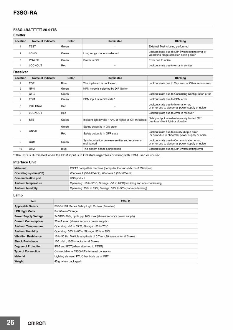
F3SG-4RA@@@@-25-01TS
Emitter
Receiver
* The LED is illuminated when the EDM input is in ON state regardless of wiring with EDM used or unused.
Interface Unit
Lamp
Location Name of Indicator Color Illuminated Blinking
1 TEST Green − External Test is being performed
2 LONG Green Long range mode is selected Lockout state due to DIP Switch setting error or Operating range selection setting error
3 POWER Green Power is ON. Error due to noise
4 LOCKOUT Red − Lockout state due to error in emitter
Location Name of Indicator Color Illuminated Blinking
1 TOP Blue The top beam is unblocked Lockout state due to Cap error or Other sensor error
2 NPN Green NPN mode is selected by DIP Switch −
3 CFG Green − Lockout state due to Cascading Configuration error
4 EDM Green EDM input is in ON state * Lockout state due to EDM error
5 INTERNAL Red − Lockout state due to Internal error, or error due to abnormal power supply or noise
6 LOCKOUT Red − Lockout state due to error in receiver
7 STB Green Incident light level is 170% or higher of ON-threshold Safety output is instantaneously turned OFF due to ambient light or vibration
8 ON/OFF
Green Safety output is in ON state −
Red Safety output is in OFF state Lockout state due to Safety Output error, or error due to abnormal power supply or noise
9 COM Green Synchronization between emitter and receiver is maintained
Lockout state due to Communication error, or error due to abnormal power supply or noise
10 BTM Blue The bottom beam is unblocked Lockout state due to DIP Switch setting error
Main unit PC/AT compatible machine (computer that runs Microsoft Windows)
Operating system (OS) Windows 7 (32-bit/64-bit), Windows 8 (32-bit/64-bit)
Communication port USB port ×1
Ambient temperature Operating: -10 to 55°C, Storage: -30 to 70°C(non-icing and non-condensing)
Ambient humidity Operating: 35% to 85%, Storage: 35% to 95%(non-condensing)
Item F39-LP
Applicable Sensor F3SG-@RA Series Safety Light Curtain (Receiver)
LED Light Color Red/Green/Orange
Power Supply Voltage 24 VDC±20%, ripple p-p 10% max.(shares sensor′s power supply)
Current Consumption 25 mA max. (shares sensor′s power supply.)
Ambient Temperature Operating: -10 to 55°C, Storage: -25 to 70°C
Ambient Humidity Operating: 35% to 85%, Storage: 35% to 95%
Vibration Resistance 10 to 55 Hz, Multiple amplitude of 0.7 mm,20 sweeps for all 3 axes
Shock Resistance 100 m/s2 , 1000 shocks for all 3 axes
Degree of Protection IP65 and IP67(When attached to F3SG)
Type of Connection Connectable to F3SG-RA′s terminal connector
Material Lighting element: PC, Other body parts: PBT
Weight 45 g (when packaged)

F3SG-RA
27
Connections (Basic Wiring Diagram)F3SG-4RA@@@@-14/-4RA@@@@-30Standalone F3SG-RA with Auto Reset mode and EDM disabled using PNP OutputsThe following is the example of Muting disabled, External Device Monitoring disabled, Auto-Reset mode, PNP outputs and External Test not used.
DIP Switch settings *1
: Indicates a switch position.
Configure functions with the DIP Switches before wiring.
Wiring Example
Note: Functional earth connection is unnecessary when you use the F3SG-R in a general industrial environment where noise control or stable power supply is considered. However, when you use the F3SG-R in an environment where there may be excessive noise from surroundings or stable power supply may be interfered, it is recommended the F3SG-R be connected to functional earth.The wiring examples in later examples do not indicate functional earth. To use functional earth, wire an earth cable according to the example above. Refer to Safety Light Curtain F3SG-R Series User's Manual for more information.
Function DIP-SW1 DIP-SW2
Receiver
EDM Disabled (factory default setting)
Auto Reset (factory default setting)
PNP (factory default setting)
Emitter External Test: 24 V Active (factory default setting)
2 ON 2 ON
3 ON 3 ON
4 ON 4 ON
7 ON 7 ON
4 ON
UnblockedBlocked
Beam state
OSSD
KM1, KM2: Safety relay with forcibly guided contacts (G7SA) or magnetic contactorM: 3-phase motor
OS
SD
1: B
lack
OS
SD
2: W
hite
24 V
DC
: Bro
wn
Not
use
d: Y
ello
w
TE
ST
: Bla
ck *
2
Not
use
d: W
hite
24 V
DC
: Bro
wn
0 V
DC
: Blu
e
Rec
eive
r
Em
itter
0 V
DC
: Blu
e
AU
X: R
ed
MU
TE
B: P
ink
MU
TE
A: G
ray
RE
SE
T: Y
ello
w *
3
F39-JG�A-L F39-JG�A-D
Power Supply
+24 VDC
0 VDC
KM1 KM2KM1
KM2
M
Functional Earth
*1.*The functions are configurable with DIP Switch. Refer to Safety Light CurtainF3SG-R Series User's Manual for more information on setting the functions bythe DIP Switch.
*2.Connect the line to 24 V via a test switch (N.O. contact) if External Test is used.*3.Connect the line to 24 V via a lockout reset switch (N.C. contact) if Lockout Reset
is used.

F3SG-RA
28
Standalone F3SG-RA with Manual Reset mode and EDM enabled using PNP OutputsThe following is the example of External Device Monitoring enabled, Manual Reset mode, PNP output and External Test in 24 V Active.
DIP Switch settings *2
: Indicates a switch position.
Configure functions with the DIP Switches before wiring.
Wiring Example
Function DIP-SW1 DIP-SW2
Receiver
EDM Enabled
Manual Reset
PNP (factory default setting)
Emitter External Test: 24 V Active (factory default setting)
2 ON 2 ON
3 ON 3 ON
4 ON 4 ON
7 ON 7 ON
4 ON
OS
SD
1 : B
lack
OS
SD
2 : W
hite
24 V
DC
: B
row
n
Not
use
d : Y
ello
w
TE
ST
: B
lack
Not
use
d : W
hite
24 V
DC
: B
row
n
0 V
DC
: B
lue
Rec
eive
r
Em
itter
0 V
DC
: B
lue
AU
X :
Red
MU
TE
B :
Pin
k
MU
TE
A :
Gra
y
RE
SE
T :
Yel
low
*1
S2
S1: Test Switch (Connect the line to 0 V if this switch is not required)S2: Lockout/Interlock Reset SwitchKM1, KM2: Safety relay with forcibly guided contacts (G7SA) or magnetic contactorM: 3-phase motor
S1
F39-JG�A-L F39-JG�A-D
KM1
KM2
KM1 KM2
Power Supply
+24 VDC
0 VDC
KM1
KM2
M
UnblockedBlocked
Test Switch (S1)
Beam state
Reset Switch (S2)
OSSD
*1.Also used as EDM input line.*2.The functions are configurable with DIP Switch. Refer to
Safety Light Curtain F3SG-R Series User's Manual for moreinformation on setting the functions by the DIP Switch.

F3SG-RA
29
Standalone F3SG-RA with Y-Joint Plug/Socket Connector using PNP outputsThe following is the example of Muting disabled, External Device Monitoring enabled, Manual Reset mode, PNP output and External Test in 24 V Active.
DIP Switch settings *3
: Indicates a switch position.
Configure functions with the DIP Switches before wiring.
Wiring Example
Function DIP-SW1 DIP-SW2
Receiver
EDM Enabled
Manual Reset
PNP (factory default setting)
Emitter External Test: 24 V Active (factory default setting)
2 ON 2 ON
3 ON 3 ON
4 ON 4 ON
7 ON 7 ON
4 ON
KM1
KM2
M
0 V
DC
: Blu
e
RE
SE
T:
Yel
low
*1
MU
TE
A: G
ray
MU
TE
B: P
ink
AU
X: R
ed
OS
SD
1: B
lack
OS
SD
2: W
hite
24 V
DC
: Bro
wn
+24 VDC
0 VDC
Power supply
IN
PLC *2
KM1 KM2
F39-JG@B-L
F39-GCNY2
F39-JG@A-D
S1
KM1
KM2
S1: Lockout/Interlock Reset SwitchKM1,KM2: External device feedbackM: 3-phase motorPLC: Programmable controller(Used for monitoring only. NOT related to safety system.)
UnblockedBlockedBeam state
Reset Switch (S1)
OSSD
*1.Also used as EDM input line.*2.When connecting to the PLC, the output mode must be
changed with the Configuration Tool.*3.The functions are configurable with DIP Switch. Refer to
Safety Light Curtain F3SG-R Series User's Manual for moreinformation on setting the functions by the DIP Switch.

F3SG-RA
30
F3SG-RA with Y-Joint Plug/Socket Connector in Standard Muting Mode/Exit-Only Muting Mode using PNP outputsThe following is the example of External Device Monitoring disabled, Auto Reset mode, PNP output and External Test in 24 V Active.
DIP Switch settings *5
: Indicates a switch position.
Configure functions with the DIP Switches before wiring.
Wiring Example
Function DIP-SW1 DIP-SW2
Receiver
EDM Disabled (factory default setting)
Auto Reset (factory default setting)
PNP (factory default setting)
Emitter External Test: 24 V Active (factory default setting)
2 ON 2 ON
3 ON 3 ON
4 ON 4 ON
7 ON 7 ON
4 ON
0 V
DC
: Blu
e
RESE
T: Y
ello
w*1
MU
TE A
: Gra
y
MU
TE B
: Pin
k
AU
X: R
ed
OS
SD
1: B
lack
OS
SD
2: W
hite
24 V
DC
: Bro
wn
+24V DC
0V
IN1IN1 IN2
Safety Controller *3 *4
F39-JG@B-LF39-JG@A-D
F39-GCNY2
S1*2
Power supply
S1: Lockout Reset Switch,Override Switch or Override Cancel Switch
ML: Muting Lamp
UnblockedBlocked
MUTE A
MUTE B
OSSD
Beam state
PLC *6
*1.Also used as EDM input line.*2.Make sure to connect an override cancel switch to the Reset
line when using the override function. Otherwise the overridestate may not be released by the override cancel switch,resulting in serious injury.
*3.Refer to page 34 for more information.*4.The safety controller and the F3SG-R must share the power
supply or be connected to the common terminal of the powersupply.
*5.The functions are configurable with DIP Switch. Refer toSafety Light Curtain F3SG-R Series User's Manual for moreinformation on setting the functions by the DIP Switch.

F3SG-RA
31
Standard Muting Mode/Exit-Only Muting Mode using PNP OutputsThe following is the example of External Device Monitoring disabled, Auto Reset mode, PNP output and External Test in 24 V Active.
DIP Switch settings *6
: Indicates a switch position.
Configure functions with the DIP Switches before wiring.
Wiring Example
Function DIP-SW1 DIP-SW2
Receiver
EDM Disabled (factory default setting)
Auto Reset (factory default setting)
PNP (factory default setting)
Emitter External Test: 24 V Active (factory default setting)
2 ON 2 ON
3 ON 3 ON
4 ON 4 ON
7 ON 7 ON
4 ON
OS
SD
1 : B
lack
OS
SD
2 : W
hite
24 V
DC
: B
row
n
Not
use
d : Y
ello
w
TE
ST
: B
lack
Not
use
d : W
hite
24 V
DC
: B
row
n
0 V
DC
: B
lue
Rec
eive
r
Em
itter
0 V
DC
: B
lue
AU
X :
Red
MU
TE
B :
Pin
k
MU
TE
A :
Gra
y
RE
SE
T :
Yel
low
*1
S1: Test Switch (Connect the line to 0 V if this switch is not required)S2: Lockout Reset Switch,
Override Switch or Override Cancel SwitchML: Muting lamp
S2*2
F39-JG@A-L F39-JG@A-D
S1
Power Supply
+24 VDC
0 VDC
Safety Controller *3 *4
Muting Actuator *5
IN1 IN2
ML
UnblockedBlocked
MUTE A
MUTE B
OSSD
Test Switch (S1)
Beam state
*1.Also used as Override input line.*2.Make sure to connect an override cancel switch to the Reset
line when using the override function. Otherwise the overridestate may not be released by the override cancel switch,resulting in serious injury.
*3.Refer to page 34 for more information.*4.The safety controller and the F3SG-R must share the power
supply or be connected to the common terminal of the powersupply.
*5.Refer to Smart Muting Actuator F3W-MA Series User's Manualfor more information.
*6.The functions are configurable with DIP Switch. Refer toSafety Light Curtain F3SG-R Series User's Manual for moreinformation on setting the functions by the DIP Switch.

F3SG-RA
32
Standard Muting Mode/Exit-Only Muting Mode with two Muting Sensors using PNP OutputsThe following is the example of External Device Monitoring disabled, Auto Reset mode, PNP output and External Test in 24 V Active.
DIP Switch settings *5
: Indicates a switch position.
Configure functions with the DIP Switches before wiring.
Wiring Example
Function DIP-SW1 DIP-SW2
Receiver
EDM Disabled (factory default setting)
Auto Reset (factory default setting)
PNP (factory default setting)
Emitter External Test: 24 V Active (factory default setting)
2 ON 2 ON
3 ON 3 ON
4 ON 4 ON
7 ON 7 ON
4 ON
OS
SD
1 : B
lack
OS
SD
2 : W
hite
24 V
DC
: B
row
n
Not
use
d : Y
ello
w
TE
ST
: B
lack
Not
use
d : W
hite
24 V
DC
: B
row
n
0 V
DC
: B
lue
Rec
eive
r
Em
itter
0 V
DC
: B
lue
AU
X :
Red
MU
TE
B :
Pin
k
MU
TE
A :
Gra
y
RE
SE
T :
Yel
low
*1
S1: Test Switch (Connect the line to 0 V if this switch is not required)S2: Lockout Reset Switch,Override Switch or Override Cancel SwitchML: Muting lampA1, B1: Muting sensor
S1 S2*2
Muting Sensor (PNP
output)
Reflector
F39-JG@A-L F39-JG@A-D
A1 B1 Power Supply
+24 VDC
0 VDC
Safety Controller *3 *4
IN1 IN2
ML
UnblockedBlocked
MUTE A
MUTE B
OSSD
Test Switch (S1)
Beam state
*1.Also used as Override input line.*2.Make sure to connect an override cancel switch to the Reset
line when using the override function. Otherwise the overridestate may not be released by the override cancel switch,resulting in serious injury.
*3.Refer to page 34 for more information.*4.The safety controller and the F3SG-R must share the power
supply or be connected to the common terminal of the powersupply.
*5.The functions are configurable with DIP Switch. Refer to SafetyLight Curtain F3SG-R Series User's Manual for more informationon setting the functions by the DIP Switch.

F3SG-RA
33
Standard Muting Mode with four Muting Sensors using PNP OutputsThe following is the example of External Device Monitoring disabled, Auto Reset mode, PNP output and External Test in 24 V Active.
DIP Switch settings *5
: Indicates a switch position.Configure functions with the DIP Switches before wiring.
Wiring Example
Function DIP-SW1 DIP-SW2
Receiver
EDM Disabled (factory default setting)
Auto Reset (factory default setting)
PNP (factory default setting)
Emitter External Test: 24 V Active (factory default setting)
2 ON 2 ON
3 ON 3 ON
4 ON 4 ON
7 ON 7 ON
4 ON
OS
SD
1 : B
lack
OS
SD
2 : W
hite
24 V
DC
: B
row
n
Not
use
d : Y
ello
w
TE
ST
: B
lack
Not
use
d : W
hite
24 V
DC
: B
row
n
0 V
DC
: B
lue
Rec
eive
r
Em
itter
0 V
DC
: B
lue
AU
X :
Red
MU
TE
B :
Pin
k
MU
TE
A :
Gra
y
RE
SE
T :
Yel
low
*1
S1: Test Switch (Connect the line to 0 V if this switch is not required)S2: Lockout Reset Switch,
Override Switch or Override Cancel SwitchML: Muting lampA1, A2, B1, B2: Muting sensor
S1 S2*2
Muting Sensor (PNP
output)
Reflector F3S
GF
3SG
A1 A2
B1 B2
Power Supply
+24 VDC
0 VDC
Safety Controller *3 *4
IN1 IN2
ML
UnblockedBlocked
MUTE A
Beam state
MUTE B
OSSD
Test Switch (S1)
F39-JG@A-L F39-JG@A-D
*1.Also used as Override input line.*2.Make sure to connect an override cancel switch to the Reset line when using
the override function. Otherwise the override state may not be released by theoverride cancel switch, resulting in serious injury.
*3.Refer to page 34 for more information.*4.The safety controller and the F3SG-R must share the power supply or be
connected to the common terminal of the power supply.*5.The functions are configurable with DIP Switch. Refer to Safety Light Curtain
F3SG-R Series User's Manual for more information on setting the functions bythe DIP Switch.

F3SG-RA
34
Pre-Resest Mode using PNP OutputThe following is the example of External Device Monitoring disabled, Pre-Reset mode, PNP output and External Test in 24 V Active.
DIP Switch settings *4
: Indicates a switch position.Configure functions with the DIP Switches before wiring.
Wiring Example
Connectable Safety Control UnitsThe F3SG-RA with PNP output can be connected to the safety control units listed in the table below.
Function DIP-SW1 DIP-SW2
Receiver
EDM Disabled (factory default setting)
Pre-Reset
PNP (factory default setting)
Emitter External Test: 24 V Active (factory default setting)
Connectable Safety Control Units (PNP output)
G9SA-301G9SA-321G9SA-501G9SB-200-BG9SB-200-DG9SB-301-BG9SB-301-DG9SE-201G9SE-401G9SE-221-T@
G9SX-AD322-TG9SX-ADA222-TG9SX-BC202G9SX-GS226-T15
G9SP-N10SG9SP-N10DG9SP-N20SNE0A-SCPU01NE1A-SCPU01NE1A-SCPU02DST1-ID12SL-1DST1-MD16SL-1DST1-MRD08SL-1NX-SIH400NX-SID800F3SP-T01
2 ON 2 ON
3 ON 3 ON
4 ON 4 ON
7 ON 7 ON
4 ON
OS
SD
1 : B
lack
OS
SD
2 : W
hite
24 V
DC
: B
row
n
Not
use
d : Y
ello
w
TE
ST
: B
lack
Not
use
d : W
hite
24 V
DC
: B
row
n
0 V
DC
: B
lue
Rec
eive
r
Em
itter
0 V
DC
: B
lue
AU
X :
Red
Not
use
d : P
ink
PR
E-R
ES
ET
: G
ray
RE
SE
T :
Yel
low
S1: Test Switch (Connect the line to 0 V if this switch is not required)S2: Lockout/Interlock Reset SwitchS3: Pre-Reset SwitchPLC: Programmable controller (Used for monitoring only. NOT related to safety system.)
S2 S3
F39-JG@A-L F39-JG@A-D
S1
Power Supply
+24 VDC
0 VDC
Safety Controller *1 *2
IN1 IN2
PLC *3
IN
Pre-Reset Switch (S3)
Beam state
Reset Switch (S2)
OSSD
UnblockedBlocked
T1: Push time: must be T1 >= 300msT2: Pre-reset limit time between Pre-reset and Reset: must be T2 <= 60sT3: Push time: must be T3 >= 300ms
T1T2
T3
*1.Refer to the following list "Connectable Safety ControlUnits" on this page.
*2.The safety controller and the F3SG-R must share thepower supply or be connected to the common terminalof the power supply.
*3.When connecting to the PLC, the output mode must bechanged with the Configuration Tool.
*4.The functions are configurable with DIP Switch. Refer toSafety Light Curtain F3SG-R Series User's Manual formore information on setting the functions by the DIPSwitch.

F3SG-RA
35
Standalone F3SG-RA with Auto Reset mode and EDM disabled using NPN OutputsThe following is the example of Muting disabled, External Device Monitoring disabled, Auto-Reset mode, NPN outputs and External Test not used.
DIP Switch settings *1
: Indicates a switch position.
Configure functions with the DIP Switches before wiring.
Wiring Example
Function DIP-SW1 DIP-SW2
Receiver
EDM Enabled
Manual Reset
NPN
Emitter External Test: 0 V Active
2 ON 2 ON
3 ON 3 ON
4 ON 4 ON
7 ON 7 ON
4 ON
UnblockedBlocked
Beam state
OSSD
KM1, KM2: Safety relay with forcibly guided contacts (G7SA) or magnetic contactorM: 3-phase motor
KM1
KM2
M
OS
SD
1: B
lack
OS
SD
2: W
hite
24 V
DC
: Bro
wn
Not
use
d: Y
ello
w
TE
ST
: Bla
ck *
2
Not
use
d: W
hite
24 V
DC
: Bro
wn
0 V
DC
: Blu
e
Rec
eive
r
Em
itter
0 V
DC
: Blu
e
AU
X: R
ed
MU
TE
B: P
ink
MU
TE
A: G
ray
RE
SE
T: Y
ello
w *
3
F39-JG@A-L F39-JG@A-D
Power Supply+24 VDC
0 VDC
KM1 KM2
*1.The functions are configurable with DIP Switch. Refer to Safety Light Curtain F3SG-RSeries User's Manual for more information on setting the functions by the DIP Switch.
*2.Connect the line to 0 V via a test switch (N.O. contact) if External Test is used.*3.Connect the line to 0 V via a lockout reset switch (N.C. contact) if Lockout Reset is used.

F3SG-RA
36
Standalone F3SG-RA with Manual Reset mode and EDM enabled using NPN OutputsThe following is the example of Muting disabled, External Device Monitoring enabled, Manual Reset mode, NPN output and External Test in 0 V Active.
DIP Switch settings *2
: Indicates a switch position.
Configure functions with the DIP Switches before wiring.
Wiring Example
Function DIP-SW1 DIP-SW2
Receiver
EDM Enabled
Manual Reset
NPN
Emitter External Test: 0 V Active
2 ON 2 ON
3 ON 3 ON
4 ON 4 ON
7 ON 7 ON
4 ON
OS
SD
1 : B
lack
OS
SD
2 : W
hite
24 V
DC
: B
row
n
Not
use
d : Y
ello
w
TE
ST
: B
lack
Not
use
d : W
hite
24 V
DC
: B
row
n
0 V
DC
: B
lue
Rec
eive
r
Em
itter
0 V
DC
: B
lue
AU
X :
Red
MU
TE
B :
Pin
k
MU
TE
A :
Gra
y
RE
SE
T :
Yel
low
*1
S2S1
F39-JG@A-L F39-JG@A-D
KM1 KM2
KM1
KM2
Power Supply
+24 VDC
0 VDC
S1: Test Switch (Connect the line to 24 V if this switch is not required)S2: Lockout/Interlock Reset SwitchKM1, KM2: Safety relay with forcibly guided contacts (G7SA) or magnetic contactorM: 3-phase motor
KM1
KM2
M
UnblockedBlocked
Test Switch (S1)
Reset Switch (S2)
OSSD
Beam state
*1.Also used as EDM input line.*2.The functions are configurable with DIP Switch. Refer to
Safety Light Curtain F3SG-R Series User's Manual for moreinformation on setting the functions by the DIP Switch.

F3SG-RA
37
Standalone F3SG-RA with Y-Joint Plug/Socket Connector using NPN outputsThe following is the example of Muting disabled, External Device Monitoring enabled, Manual Reset mode, NPN output and External Test in 24 V Active.
DIP Switch settings *3
: Indicates a switch position.
Configure functions with the DIP Switches before wiring.
Wiring Example
Function DIP-SW1 DIP-SW2
Receiver
EDM Enabled
Manual Reset
NPN
Emitter External Test: 24 V Active (factory default setting)
2 ON 2 ON
3 ON 3 ON
4 ON 4 ON
7 ON 7 ON
4 ON
KM1
KM2
M
0 V
DC
: Blu
e
RE
SE
T:
Yel
low
*1
MU
TE
A: G
ray
MU
TE
B: P
ink
AU
X: R
ed
OS
SD
1: B
lack
OS
SD
2: W
hite
24 V
DC
: Bro
wn
+24 VDC
0 VDC
Power supply
IN
PLC *2
KM1 KM2
KM1
KM2
F39-JG@B-LF39-GCNY2
F39-JG@A-D
S1
S1: Lockout/Interlock Reset SwitchKM1,KM2: External device feedbackM: 3-phase motorPLC: Programmable controller
(Used for monitoring only. NOT related to safety system.)
UnblockedBlocked
Reset Switch (S1)
OSSD
Beam state
*1.Also used as EDM input line.*2.When connecting to the PLC, the output mode must be
changed with the Configuration Tool.*3.The functions are configurable with DIP Switch. Refer to
Safety Light Curtain F3SG-R Series User's Manual for moreinformation on setting the functions by the DIP Switch.

F3SG-RA
38
Standard Muting Mode/Exit-Only Muting Mode using NPN OutputsThe following is the example of External Device Monitoring enabled, Auto Reset mode, NPN output and External Test in 0 V Active.
DIP Switch settings *3
: Indicates a switch position.
Configure functions with the DIP Switches before wiring.
Wiring Example
Function DIP-SW1 DIP-SW2
Receiver
EDM Enabled
Auto Reset (factory default setting)
NPN
Emitter External Test: 0 V Active
2 ON 2 ON
3 ON 3 ON
4 ON 4 ON
7 ON 7 ON
4 ON
OS
SD
1 : B
lack
OS
SD
2 : W
hite
24 V
DC
: B
row
n
Not
use
d : Y
ello
w
TE
ST
: B
lack
Not
use
d : W
hite
24 V
DC
: B
row
n
0 V
DC
: B
lue
Rec
eive
r
Em
itter
0 V
DC
: B
lue
AU
X :
Red
MU
TE
B :
Pin
k
MU
TE
A :
Gra
y
RE
SE
T :
Yel
low
*1
S1: Test Switch (Connect the line to 24 V if this switch is not required)S2: Override Cancel SwitchS3: Lockout Reset Switch or Override SwitchS4, S5: Muting sensorKM1, KM2: Safety relay with forcibly guided contacts (G7SA) or magnetic contactorM: 3-phase motorML: Muting lamp
S1S3
F39-JG@A-L F39-JG@A-D
Power Supply
+24 VDC
0 VDCS5S2
*2S4
KM1 KM2ML
KM1
KM2
KM1
KM2
M
UnblockedBlocked
MUTE A
MUTE B
OSSD
Test Switch (S1)
Beam state
*1.Also used as Override input line.*2.Make sure to connect an override cancel switch to the Reset line
when using the override function. Otherwise the override state maynot be released by the override cancel switch, resulting in seriousinjury.
*3.The functions are configurable with DIP Switch. Refer to SafetyLight Curtain F3SG-R Series User's Manual for more information onsetting the functions by the DIP Switch.

F3SG-RA
39
Standard Muting Mode/Exit-Only Muting Mode with two Muting Sensors using NPN OutputsThe following is the example of External Device Monitoring enabled, Auto Reset mode, NPN output and External Test in 0 V Active.
DIP Switch settings *3
: Indicates a switch position.
Configure functions with the DIP Switches before wiring.
Wiring Example
Function DIP-SW1 DIP-SW2
Receiver
EDM Enabled
Auto Reset (factory default setting)
NPN
Emitter External Test: 0 V Active
2 ON 2 ON
3 ON 3 ON
4 ON 4 ON
7 ON 7 ON
4 ON
UnblockedBlocked
MUTE A
Beam state
MUTE B
OSSD
Test Switch (S1)
OS
SD
1 : B
lack
OS
SD
2 : W
hite
24 V
DC
: B
row
n
Not
use
d : Y
ello
w
TE
ST
: B
lack
Not
use
d : W
hite
24 V
DC
: B
row
n
0 V
DC
: B
lue
Rec
eive
r
Em
itter
0 V
DC
: B
lue
AU
X :
Red
MU
TE
B :
Pin
k
MU
TE
A :
Gra
y
RE
SE
T :
Yel
low
*1
S1: Test Switch (Connect the line to 24 V if this switch is not required)S2: Override Cancel SwitchS3: Lockout Reset Switch or Override SwitchKM1, KM2: Safety relay with forcibly guided contacts (G7SA) or magnetic contactorM: 3-phase motorML: Muting lampA1, B1: Muting sensor
S1 S3
Muting Sensor (NPN
output)
Reflector
S2*2
A1 B1 Power Supply
+24 VDC
0 VDC
ML KM1 KM2
KM1
KM2
KM1
KM2
M
F39-JG@A-L F39-JG@A-D
*1.Also used as Override input line.*2.Make sure to connect an override cancel switch to the Reset line
when using the override function. Otherwise the override statemay not be released by the override cancel switch, resulting inserious injury.
*3.The functions are configurable with DIP Switch. Refer to SafetyLight Curtain F3SG-R Series User's Manual for more informationon setting the functions by the DIP Switch.

F3SG-RA
40
Standard Muting Mode with four Muting Sensors using NPN OutputsThe following is the example of External Device Monitoring enabled, Auto Reset mode, NPN output and External Test in 0 V Active.
DIP Switch settings *3
: Indicates a switch position.Configure functions with the DIP Switches before wiring.
Wiring Example
Function DIP-SW1 DIP-SW2
Receiver
EDM Enabled
Auto Reset (factory default setting)
NPN
Emitter External Test: 0 V Active
2 ON 2 ON
3 ON 3 ON
4 ON 4 ON
7 ON 7 ON
4 ON
OS
SD
1 : B
lack
OS
SD
2 : W
hite
24 V
DC
: B
row
n
Not
use
d : Y
ello
w
TE
ST
: B
lack
Not
use
d : W
hite
24 V
DC
: B
row
n
0 V
DC
: B
lue
Rec
eive
r
Em
itter
0 V
DC
: B
lue
AU
X :
Red
MU
TE
B :
Pin
k
MU
TE
A :
Gra
y
RE
SE
T :
Yel
low
*1
S1 S3S2*2
B1 B2
S1: Test Switch (Connect the line to 24 V if this switch is not required)S2: Override Cancel SwitchS3: Lockout Reset Switch or Override SwitchKM1, KM2: Safety relay with forcibly guided contacts (G7SA) or magnetic contactorM: 3-phase motorML: Muting lampA1, A2, B1, B2: Muting sensor
F3S
G
Muting Sensor (NPN
output)
Reflector
F3S
G
A1 A2
Power Supply
+24 VDC
0 VDC
ML KM1 KM2
KM1
KM2
M
KM1
KM2
UnblockedBlocked
MUTE A
MUTE B
OSSD
Test Switch (S1)
Beam state
F39-JG@A-L F39-JG@A-D
*1.Also used as Override input line.*2.Make sure to connect an override cancel switch to the Reset line when
using the override function. Otherwise the override state maynot bereleased by the override cancel switch, resulting in serious injury.
*3.The functions are configurable with DIP Switch. Refer to Safety LightCurtain F3SG-R Series User's Manual for more information on settingthe functions by the DIP Switch.

F3SG-RA
41
Pre-Resest Mode using NPN OutputThe following is the example of External Device Monitoring enabled, Pre-Reset mode, NPN output and External Test in 0 V Active.
DIP Switch settings *2
: Indicates a switch position.
Configure functions with the DIP Switches before wiring.
Wiring Example
The F3SG-RA with NPN output can be connected to the safety control unit listed in the table below.
Function DIP-SW1 DIP-SW2
Receiver
EDM Enabled
Pre-Reset
NPN
Emitter External Test: 0 V Active
Connectable Safety Control Units (NPN output)
G9SA-301-P
2 ON 2 ON
3 ON 3 ON
4 ON 4 ON
7 ON 7 ON
4 ON
OS
SD
1 : B
lack
OS
SD
2 : W
hite
24 V
DC
: B
row
n
Not
use
d : Y
ello
w
TE
ST
: B
lack
Not
use
d : W
hite
24 V
DC
: B
row
n
0 V
DC
: B
lue
Rec
eive
r
Em
itter
0 V
DC
: B
lue
AU
X :
Red
Not
use
d : P
ink
PR
E-R
ES
ET
: G
ray
RE
SE
T :
Yel
low
S1: Test Switch (Connect the line to 24 V if this switch is not required)S2: Lockout/Interlock Reset SwitchS3: Pre-Reset SwitchKM1, KM2: External device feedbackM: 3-phase motorPLC: Programmable controller (Used for monitoring only. NOT related to safety system.)
S1S2 S3
F39-JG@A-L F39-JG@A-D
Power Supply
+24 VDC
0 VDC
KM1
KM2
KM1
KM2
M
PLC *1
IN
Pre-Reset Switch(S3)
Beam state
Reset Switch (S2)
OSSD
UnblockedBlocked
T1: Push time: must be T1 >= 300msT2: Pre-reset limit time between Pre-reset and Reset: must be T2 <= 60sT3: Push time: must be T3 >= 300ms
T1T2
T3
KM1 KM2
*1.When connecting to the PLC, the output mode must bechanged with the Configuration Tool.
*2.The functions are configurable with DIP Switch. Refer to SafetyLight Curtain F3SG-R Series User's Manual for more informationon setting the functions by the DIP Switch.

F3SG-RA
42
F3SG-4RA@@@@-25-01TSEDM disabled, External Test unused and PNP OutputsThe following is the example of EDM disabled, PNP outputs and External Test unused.
DIP Switch settings *1
: Indicates a switch position.
Configure functions with the DIP Switches before wiring.
Wiring Example
Function DIP-SW1 DIP-SW2
ReceiverEDM Disabled (factory default setting)
PNP (factory default setting)
Emitter External Test: 24 V Inactive (factory default setting)
2 ON 2 ON
7 ON 7 ON
4 ON
E1: 24VDC power supply (S8VS)
Shi
elde
d w
ire
Shi
elde
d w
ire
IN1 IN2E1 +DC24V
0VSafetyController *4 *5
24 V
DC
: Bro
wn
24 V
DC
: Bro
wn
TE
ST
: Bla
ck *
2
0 V
DC
: Blu
e
OS
SD
1: B
lack
OS
SD
2: W
hite
0 V
DC
: Blu
e
ED
M in
put:
Red
*3
Not
use
d: P
ink
Not
use
d: G
ray
Not
use
d: R
ed
Not
use
d: P
ink
Not
use
d: G
ray
Not
use
d: Y
ello
w
Not
use
d: W
hite
AU
X: Y
ello
w
Em
itter
Rec
eive
rF39-JD@A-L F39-JD@A-D
OSSD
UnblockedBlocked
*1.The functions are configurable with DIP Switch. Refer to Safety Light Curtain F3SG-4RA@@@@-25-01TS Series User's Manual formore information on setting the functions by the DIP Switch.
*2.When the external test function is used, connect to 24V via the test switch (N.C. contact).*3.Also used for the lockout reset input. When using the lockout reset function, connect to 24V via lockout reset switch (N.C. contact). *4.Refer to User's Manual for more information.*5.The safety controller and the F3SG-RA must share the power supply or be connected to the common terminal of the power supply.

F3SG-RA
43
EDM enabled, External Test 0V Inactive and NPN OutputsThe following is the example of External Device Monitoring enabled, NPN outputs and External Test in 0 V Inactive.
DIP Switch settings *1
: Indicates a switch position.
Configure functions with the DIP Switches before wiring.
Wiring Example
Function DIP-SW1 DIP-SW2
ReceiverEDM Enabled
NPN
Emitter External Test: 0 V Inactive
2 ON 2 ON
7 ON 7 ON
4 ON
KM1 KM2
PLC
INE1 +DC24V
0V
S1KM1
KM2
PLC input
UnblockedBlocked
External Test Switch(S1)
OSSD
KM1, KM2 NO contact
PLC output
LockoutState
S1: External test switch(connect to 0V if a switch is not required)KM1, KM2: Safety relay with forcibly guided contacts (G7SA) or magnetic contactorE1: 24VDC power supply (S8VS)PLC: Programmable controller (Used for monitoring -- not related to safety system)
Not
use
d: Y
ello
w
Not
use
d: W
hite
Rec
eive
r
Em
itter
0 V
DC
: Blu
e
F39-JD@A-L F39-JD@A-D
Shi
elde
d w
ire
Shi
elde
d w
ire
24 V
DC
: Bro
wn
24 V
DC
: Bro
wn
TE
ST
: Bla
ck
OS
SD
1: B
lack
OS
SD
2: W
hite
0 V
DC
: Blu
e
ED
M in
put:
Red
*2
Not
use
d: P
ink
Not
use
d: G
ray
Not
use
d: R
ed
Not
use
d: P
ink
Not
use
d: G
ray
AU
X: Y
ello
w
*1.The functions are configurable with DIP Switch. Refer to Safety Light Curtain F3SG-4RA@@@@-25-01TS Series User's Manual formore information on setting the functions by the DIP Switch.
*2.Also used for the lockout reset input. When using the lockout reset function connect to 0V via lockout reset switch (N.C. contact).

F3SG-RA
44
Connectable Safety Control UnitsThe F3SG-R with PNP output can be connected to the safety control units listed in the table below.
The F3SG-R with NPN output can be connected to the safety control unit listed in the table below.
Connectable Safety Control Units (PNP output)
G9SA-301G9SA-321G9SA-501G9SB-200-BG9SB-200-DG9SB-301-BG9SB-301-DG9SE-201G9SE-401G9SE-221-T
G9SX-AD322-TG9SX-ADA222-TG9SX-BC202G9SX-GS226-T15
G9SP-N10SG9SP-N10DG9SP-N20SNE0A-SCPU01NE1A-SCPU01NE1A-SCPU02DST1-ID12SL-1DST1-MD16SL-1DST1-MRD08SL-1NX-SIH400NX-SID800F3SP-T01
Connectable Safety Control Units (NPN output)
G9SA-301-P

F3SG-RA
45
Input/Output CircuitF3SG-4RA@@@@-14/-4RA@@@@-30Entire Circuit DiagramThe entire circuit diagram of the F3SG-R is shown below.The numbers in the circles indicate the connector's pin numbers.
PNP Output
2
1
5
8
7
6
+24 VDC1
2
4
Brown
Black TEST
White Not used
Blue
Brown
White OSSD 2
Pink MUTE B
Gray MUTE A
Black OSSD 1
Red AUX
Blue
3
Reset input circuit
4Muting input circuit B
3Muting input circuit A
Yellow RESET
0 VDC
5Yellow Not used
Load
Indicator
EmitterMain Circuit
Test Input Circuit
ReceiverMain Circuit 2
ReceiverMain Circuit 1
IndicatorLoad
Load

F3SG-RA
46
NPN Output
Input Circuit Diagram by FunctionThe input circuit diagrams of by function are shown below.
PNP Output
NPN Output
2
1
5
8
7
6
+24 VDC1
2
4
Brown
Black TEST
White Not used
Blue
Brown
Yellow
White OSSD 2
Pink MUTE B
Gray MUTE A
Black OSSD 1
Red AUX
Blue
3
Reset input circuit
4Muting input circuit B
3Muting input circuit A
RESET
0 VDC
5Yellow Not used
Indicator
EmitterMain Circuit
Test Input Circuit
ReceiverMain Circuit 2
ReceiverMain Circuit 1
Indicator
Load
Load
Load
Emitter Main Circuit
+24 VDC
0 VDC
5 V
Short circuit current:3 mA
<Input circuit (Test input)>
Receiver Main Circuit
+24 VDC
0 VDC
Short circuit current *
<Input circuit (Reset input, Muting inputs A/B)>
Receiver Main Circuit
+24 VDC
0 VDC
Short circuit current *
<Input circuit (Reset, Muting inputs A/B)>
Emitter Main Circuit
+24 VDC
0 VDC
5 V
Short circuit current:3 mA
<Input circuit (Test input)>
*Short circuit current: 5mA (Reset input), 3mA (Muting inputs A/B)

F3SG-RA
47
F3SG-4RA@@@@-25-01TSEntire Circuit DiagramThe entire circuit diagram of the F3SG-R is shown below.The numbers in the circles indicate the connector's pin numbers.
PNP Output
2
8
3
4
7
1
+24 VDC2
3
4
Brown
Black TEST
Yellow Not used
1White Not used
Blue
Brown
Red
White OSSD 2
Pink Not used
Gray Not used
Black OSSD 1
Yellow AUX
Blue
7
EDMcircuit
6
5
EDM input
0 VDC
5Gray Not used
6Pink Not used
8Red Not used
Load
Indicator
EmitterMain Circuit
Test Input Circuit
ReceiverMain Circuit 2
ReceiverMain Circuit 1
IndicatorLoad
Load
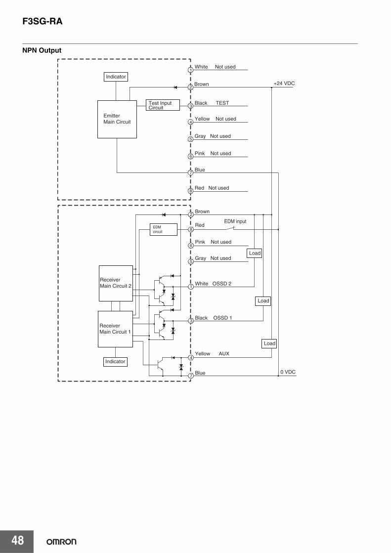
F3SG-RA
48
NPN Output
2
8
3
4
7
1
Brown
Red
White OSSD 2
Pink Not used
Gray Not used
Black OSSD 1
Yellow AUX
Blue
EDMcircuit
6
5
EDM input
0 VDC
ReceiverMain Circuit 2
ReceiverMain Circuit 1
Indicator
Load
Load
Load
+24 VDC2
3
4
Brown
Black TEST
Yellow Not used
1White Not used
Blue7
5Gray Not used
6Pink Not used
8Red Not used
Indicator
EmitterMain Circuit
Test Input Circuit

F3SG-RA
49
Input Circuit Diagram by FunctionThe input circuit diagrams of by function are shown below.
Emitter Main Circuit
+24 VDC
0 VDC
5 V
Short circuit current:Approximately 3 mA
<Input circuit (Test input)>
Receiver Main Circuit
+24 VDC
0 VDC
Short circuit current:Approximately 6.5 mA
<Input circuit (EDM input)>
24V Inactive PNP Output
Receiver Main Circuit
+24 VDC
0 VDC
Short circuit current:Approximately 8 mA
<Input circuit (EDM input)>
Emitter Main Circuit
+24 VDC
0 VDC
5 V
Short circuit current:Approximately 2.0 mA
<Input circuit (Test input)>
*Short circuit current: 5mA (Reset input), 3mA (Muting inputs A/B)
0V Inactive NPN Output

F3SG-RA
50
Dimensions (Unit: mm)
F3SG-4RA@@@@-14/-4RA@@@@-30Mounted with Standard Fixed Brackets (F39-LGF)
Backside Mounting
* Mounting an emitter or receiver with one bracket is possible for the models of protective height of 0160 to 0270. In this case, locate this bracket at half the Dimension A (or at the center of the sensor length).
2-M5 or M6
2-M5 or M6
A
6.4
5151
35
9.2
66
StandardFixed Bracket(F39-LGF)
StandardFixed Bracket(F39-LGF)
35
40
50.3
5
D
P
24.85
51
150
max
F
150
max
C2
(Pro
tect
ive
heig
ht fo
r 14
mm
)
C1
(Pro
tect
ive
heig
ht fo
r 30
mm
)
33 1843
F
24.85
A
150
max
150
max
< Screw: M5 or M6 >
F3SG- RA -30 Series Dimension A C1+18
Dimension C1 4-digit number of the type name(Protective height)
Dimension D C1-50
Dimension P 20
Protective height(C1)
Number of Standard Fixed Brackets Dimension F
0190 to 1230 2 * 1000 mm max.
1310 to 2270 3 1000 mm max.
2350 to 2510 4 1000 mm max.
F3SG- RA -14 Series Dimension A C2+48
Dimension C2 4-digit number of the type name(Protective height)
Dimension D C2-20
Dimension P 10
Protective height(C2)
Number of Standard Fixed Brackets Dimension F
0160 to 1200 2 * 1000 mm max.
1280 to 2080 3 1000 mm max.

F3SG-RA
51
Side Mounting
* Mounting an emitter or receiver with one bracket is possible for the models of protective height of 0160 to 0270. In this case, locate this bracket at half the Dimension A (or at the center of the sensor length).
StandardFixed Bracket(F39-LGF)
StandardFixed Bracket(F39-LGF)
A
35
40
2-M5 or M6
2-M5 or M6
51
9.2
51
35
6.4
66
50.3
5
51
150
max
150
max
F
42.35
A
150
max
150
max
F
P
D
C1
(Pro
tect
ive
heig
ht fo
r 30
mm
)
33 1843
C2
(Pro
tect
ive
heig
ht fo
r 14
mm
)
< Screw: M5 or M6 >
F3SG- RA -30 Series Dimension A C1+18
Dimension C1 4-digit number of the type name(Protective height)
Dimension D C1-50
Dimension P 20
Protective height(C1)
Number of Standard Fixed Brackets Dimension F
0190 to 1230 2 * 1000 mm max.
1310 to 2270 3 1000 mm max.
2350 to 2510 4 1000 mm max.
F3SG- RA -14 Series Dimension A C2+48
Dimension C2 4-digit number of the type name(Protective height)
Dimension D C2-20
Dimension P 10
Protective height(C2)
Number of Standard Fixed Brackets Dimension F
0160 to 1200 2 * 1000 mm max.
1280 to 2080 3 1000 mm max.
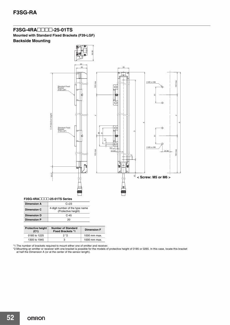
F3SG-RA
52
F3SG-4RA@@@@-25-01TSMounted with Standard Fixed Brackets (F39-LGF)
Backside Mounting
*1.The number of brackets required to mount either one of emitter and receiver.*2.Mounting an emitter or receiver with one bracket is possible for the models of protective height of 0185 or 0265. In this case, locate this bracket
at half the Dimension A (or at the center of the sensor length).
A
6.4
5151
35
9.2
66
35
40
50.3
5
D
P
24.85
51
F
43
F
24.85
A
20.5
2-M5 or M6
2-M5 or M6
Standard Fixed Bracket
Standard Fixed Bracket
(F39-LGF)
(F39-LGF)
150
max
150
max
C (
Pro
tect
ive
heig
ht)
150
max
150
max
< Screw: M5 or M6 >
F3SG-4RA@@@@-25-01TS Series Dimension A C+23
Dimension C 4-digit number of the type name(Protective height)
Dimension D C-45
Dimension P 20
Protective height(C1)
Number of Standard Fixed Brackets *1 Dimension F
0185 to 1225 2 *2 1000 mm max.
1305 to 1945 3 1000 mm max.

F3SG-RA
53
Side Mounting
*1.The number of brackets required to mount either one of emitter and receiver.*2.Mounting an emitter or receiver with one bracket is possible for the models of protective height of 0185 or 0265. In this case, locate this bracket
at half the Dimension A (or at the center of the sensor length).
Standard Fixed Bracket (F39-LGF)
A
35
40
51
9.2
51
35
6.4
66
50.3
5
51
F
42.35
A
F
P
D
43 20.5
Standard Fixed Bracket
Standard Fixed Bracket
(F39-LGF)
(F39-LGF)
2-M5 or M6
2-M5 or M6
150
max
150
max
150
max
150
max
C (
Pro
tect
ive
heig
ht)
< Screw: M5 or M6 >
F3SG-4RA@@@@-25-01TS Series Dimension A C+23
Dimension C 4-digit number of the type name(Protective height)
Dimension D C-45
Dimension P 20
Protective height(C1)
Number of Standard Fixed Brackets *1 Dimension F
0185 to 1225 2 *2 1000 mm max.
1305 to 1945 3 1000 mm max.
51
8
(23.1)
(25.8)
9.2
66
6.4
32.1
36
Material: ZDC2
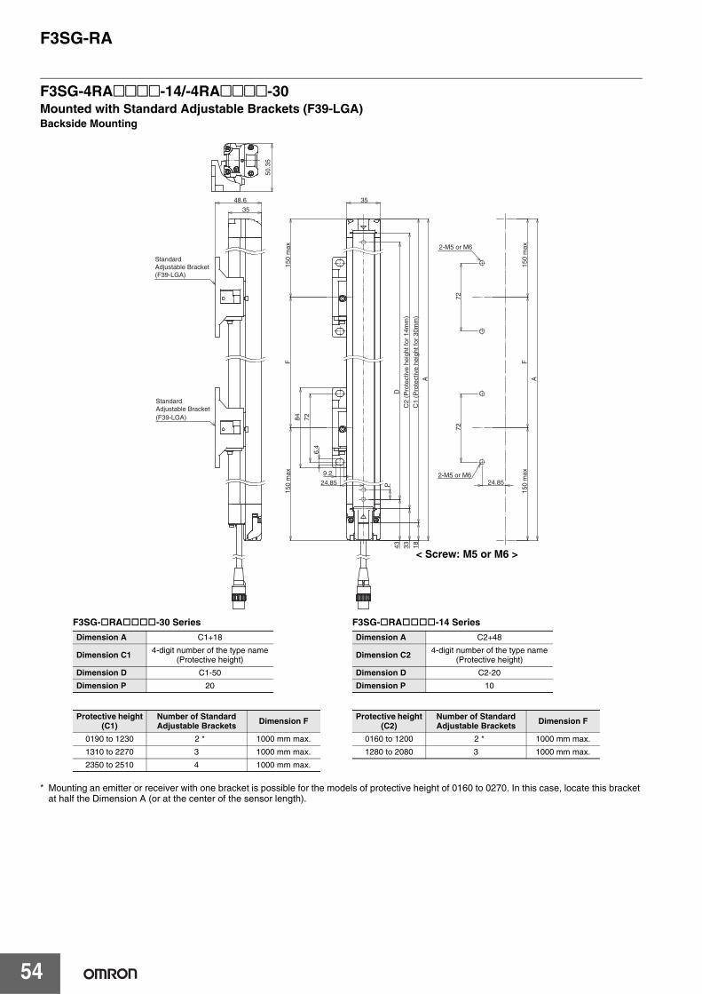
F3SG-RA
54
F3SG-4RA@@@@-14/-4RA@@@@-30Mounted with Standard Adjustable Brackets (F39-LGA)Backside Mounting
* Mounting an emitter or receiver with one bracket is possible for the models of protective height of 0160 to 0270. In this case, locate this bracket at half the Dimension A (or at the center of the sensor length).
StandardAdjustable Bracket(F39-LGA)
StandardAdjustable Bracket(F39-LGA)
35
48.6
50.3
5
2-M5 or M6
2-M5 or M6
35
A
72
9.2
72
6.4
84
P
72
24.85
150
max
150
max
F
D
C2
(Pro
tect
ive
heig
ht fo
r 14
mm
)
C1
(Pro
tect
ive
heig
ht fo
r 30
mm
)
33 1843
F
A
24.85
150
max
150
max
< Screw: M5 or M6 >
F3SG- RA -30 Series Dimension A C1+18
Dimension C1 4-digit number of the type name(Protective height)
Dimension D C1-50
Dimension P 20
Protective height(C1)
Number of Standard Adjustable Brackets Dimension F
0190 to 1230 2 * 1000 mm max.
1310 to 2270 3 1000 mm max.
2350 to 2510 4 1000 mm max.
F3SG- RA -14 Series Dimension A C2+48
Dimension C2 4-digit number of the type name(Protective height)
Dimension D C2-20
Dimension P 10
Protective height(C2)
Number of Standard Adjustable Brackets Dimension F
0160 to 1200 2 * 1000 mm max.
1280 to 2080 3 1000 mm max.

F3SG-RA
55
Side Mounting
* Mounting an emitter or receiver with one bracket is possible for the models of protective height of 0160 to 0270. In this case, locate this bracket at half the Dimension A (or at the center of the sensor length).
50.3
5
StandardAdjustable Bracket(F39-LGA)
StandardAdjustable Bracket(F39-LGA)
35
A
48.6
2-M5 or M6
2-M5 or M6
7272
35
6.4
9.2
8472
150
max
150
max
F
42.35
A
150
max
150
max
F
P
D
C2
(Pro
tect
ive
heig
ht fo
r 14
mm
)
C1
(Pro
tect
ive
heig
ht fo
r 30
mm
)
33 1843
< Screw: M5 or M6 >
F3SG- RA -30 Series Dimension A C1+18
Dimension C1 4-digit number of the type name(Protective height)
Dimension D C1-50
Dimension P 20
Protective height(C1)
Number of Standard Adjustable Brackets Dimension F
0190 to 1230 2 * 1000 mm max.
1310 to 2270 3 1000 mm max.
2350 to 2510 4 1000 mm max.
F3SG- RA -14 Series Dimension A C2+48
Dimension C2 4-digit number of the type name(Protective height)
Dimension D C2-20
Dimension P 10
Protective height(C2)
Number of Standard Adjustable Brackets Dimension F
0160 to 1200 2 * 1000 mm max.
1280 to 2080 3 1000 mm max.

F3SG-RA
56
F3SG-4RA@@@@-25-01TSMounted with Standard Adjustable Brackets (F39-LGA)Backside Mounting
*1.The number of brackets required to mount either one of emitter and receiver.*2.Mounting an emitter or receiver with one bracket is possible for the models of protective height of 0185 or 0265. In this case, locate this bracket
at half the Dimension A (or at the center of the sensor length).
35
48.6
50.3
5
35
A
72
9.2
72
6.4
84
P
72
24.85
F
D
43
F
A
24.85
20.5
Standard Adjustable Bracket(F39-LGA)
Standard Adjustable Bracket(F39-LGA)
2-M5 or M6
2-M5 or M6
150
max
150
max
C (
Pro
tect
ive
heig
ht)
150
max
150
max
< Screw: M5 or M6 >
F3SG-4RA -25-01TS Series Dimension A C+23
Dimension C 4-digit number of the type name(Protective height)
Dimension D C-45
Dimension P 20
Protective height(C)
Number of Standard Adjustable Brackets *1 Dimension F
0185 to 1225 2 *2 1000 mm max.
1305 to 1945 3 1000 mm max.

F3SG-RA
57
Side Mounting
*1.The number of brackets required to mount either one of emitter and receiver.*2.Mounting an emitter or receiver with one bracket is possible for the models of protective height of 0185 or 0265. In this case, locate this bracket
at half the Dimension A (or at the center of the sensor length).
Standard Adjustable Bracket (F39-LGA)
50.3
5
35
A
48.6
7272
35
6.4
9.28472
F42.35
A
F
P
D
43 20.5
Standard Adjustable Bracket(F39-LGA)
Standard Adjustable Bracket(F39-LGA)
150
max
150
max
150
max
150
max
C (P
rote
ctiv
e he
ight
)
2-M5 or M6
2-M5 or M6
< Screw: M5 or M6 >
F3SG-4RA -25-01TS Series Dimension A C+23
Dimension C 4-digit number of the type name(Protective height)
Dimension D C-45
Dimension P 20
Protective height(C)
Number of Standard Adjustable Brackets *1 Dimension F
0185 to 1225 2 *2 1000 mm max.
1305 to 1945 3 1000 mm max.
8
72
42
45.1
84
9.2
6.4
32.9
(31.8)
(34.5)
Material: ZDC2 ,Fluorochemical lubricant oil
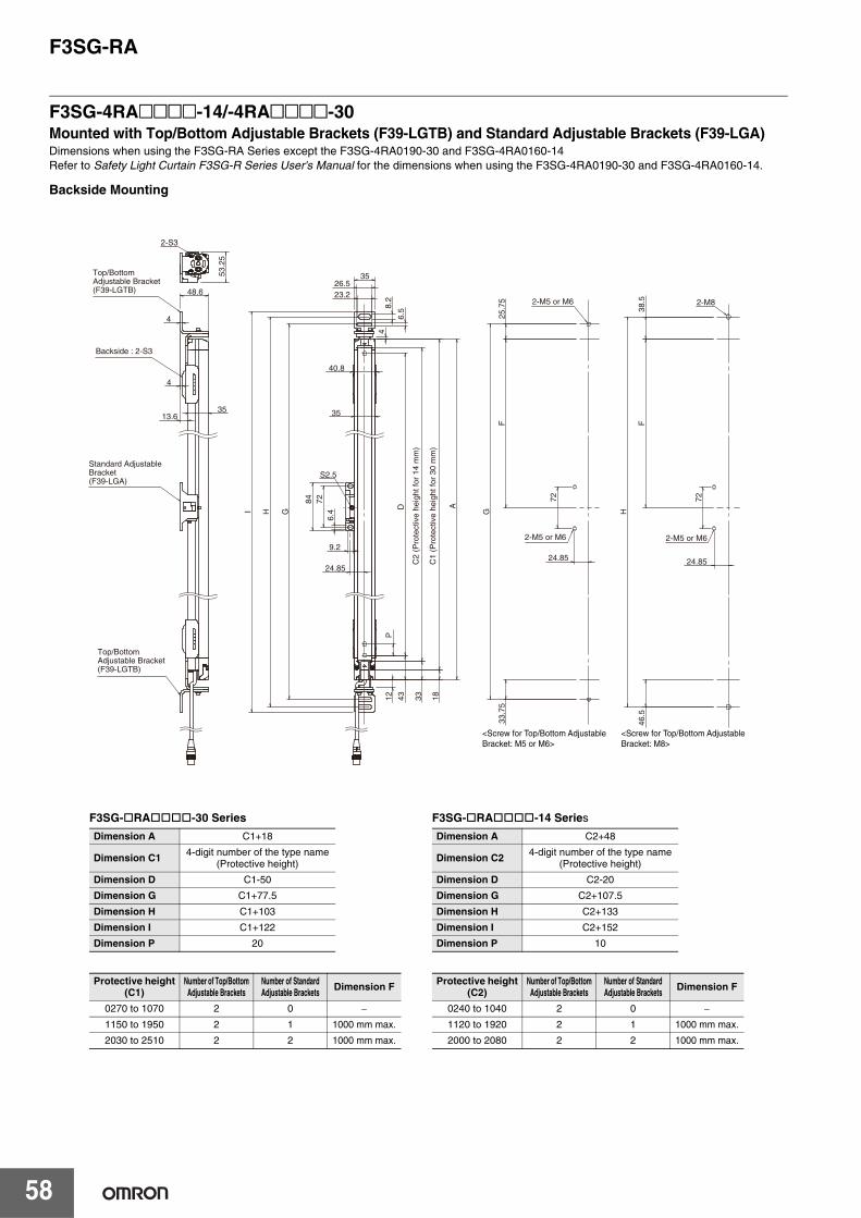
F3SG-RA
58
F3SG-4RA@@@@-14/-4RA@@@@-30Mounted with Top/Bottom Adjustable Brackets (F39-LGTB) and Standard Adjustable Brackets (F39-LGA)Dimensions when using the F3SG-RA Series except the F3SG-4RA0190-30 and F3SG-4RA0160-14Refer to Safety Light Curtain F3SG-R Series User's Manual for the dimensions when using the F3SG-4RA0190-30 and F3SG-4RA0160-14.
Backside Mounting
<Screw for Top/Bottom Adjustable Bracket: M5 or M6>
<Screw for Top/Bottom Adjustable Bracket: M8>
Standard Adjustable Bracket(F39-LGA)
Top/Bottom Adjustable Bracket(F39-LGTB)
Top/Bottom Adjustable Bracket(F39-LGTB)
Backside : 2-S3
2-M5 or M6
2-M5 or M6
2-M5 or M6
C1
(Pro
tect
ive
heig
ht fo
r 30
mm
)
C2
(Pro
tect
ive
heig
ht fo
r 14
mm
)
2-M8
S2.5
12
35
40.8
G
H
I
26.5
35
23.2
8.2
A
9.2
72
6.4
84
6.5
4
2-S3
53.
25
48.6
35 13.6
4
4
18
33
43
D
P
F
F
25.
75
24.85
46.
5
H
38.
5
G
33.
75
24.85 7
2 24.85
72
F3SG- RA -30 Series Dimension A C1+18
Dimension C1 4-digit number of the type name(Protective height)
Dimension D C1-50
Dimension G C1+77.5
Dimension H C1+103
Dimension I C1+122
Dimension P 20
Protective height(C1)
Number of Top/BottomAdjustable Brackets
Number of Standard Adjustable Brackets Dimension F
0270 to 1070 2 0 −
1150 to 1950 2 1 1000 mm max.
2030 to 2510 2 2 1000 mm max.
F3SG- RA -14 Series Dimension A C2+48
Dimension C2 4-digit number of the type name(Protective height)
Dimension D C2-20
Dimension G C2+107.5
Dimension H C2+133
Dimension I C2+152
Dimension P 10
Protective height(C2)
Number of Top/BottomAdjustable Brackets
Number of Standard Adjustable Brackets Dimension F
0240 to 1040 2 0 −
1120 to 1920 2 1 1000 mm max.
2000 to 2080 2 2 1000 mm max.

F3SG-RA
59
Side Mounting
Top/Bottom Adjustable Bracket(F39-LGTB)
Top/Bottom Adjustable Bracket(F39-LGTB)
Standard Adjustable Bracket(F39-LGA)
Backside : 2-S3
2-M5 or M6
2-M5 or M6
2-M5 or M6
C1
(Pro
tect
ive
heig
ht fo
r 30
mm
)
C2
(Pro
tect
ive
heig
ht fo
r 14
mm
)
<Screw for Top/Bottom Adjustable Bracket: M5 or M6>
<Screw for Top/Bottom Adjustable Bracket: M8>
2-M8
40.8
35
A
4
51.65
4
12
S2.5
35
23.2 26.5
35
6.5
8.2
H
I
84
9.2
6.4
72 G
9.6
2-S3
50.35
42.35
18
33
43
D
P
F
F
F
H
38.
5 4
6.5
33.
75
25.
75
G
72 72
F3SG- RA -30 Series Dimension A C1+18
Dimension C1 4-digit number of the type name(Protective height)
Dimension D C1-50
Dimension G C1+77.5
Dimension H C1+103
Dimension I C1+122
Dimension P 20
Protective height(C1)
Number of Top/BottomAdjustable Brackets
Number of Standard Adjustable Brackets Dimension F
0270 to 1070 2 0 −
1150 to 1950 2 1 1000 mm max.
2030 to 2510 2 2 1000 mm max.
F3SG- RA -14 Series Dimension A C2+48
Dimension C2 4-digit number of the type name(Protective height)
Dimension D C2-20
Dimension G C2+107.5
Dimension H C2+133
Dimension I C2+152
Dimension P 10
Protective height(C2)
Number of Top/BottomAdjustable Brackets
Number of Standard Adjustable Brackets Dimension F
0240 to 1040 2 0 −
1120 to 1920 2 1 1000 mm max.
2000 to 2080 2 2 1000 mm max.
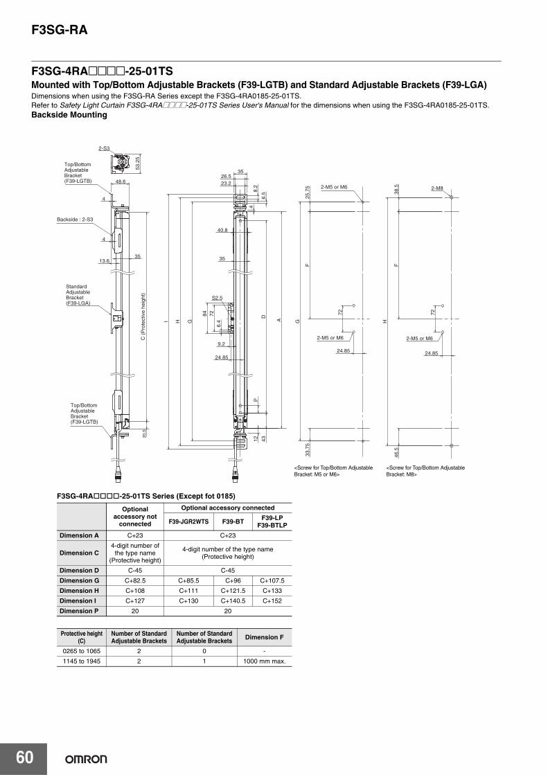
F3SG-RA
60
F3SG-4RA@@@@-25-01TSMounted with Top/Bottom Adjustable Brackets (F39-LGTB) and Standard Adjustable Brackets (F39-LGA)Dimensions when using the F3SG-RA Series except the F3SG-4RA0185-25-01TS.Refer to Safety Light Curtain F3SG-4RA@@@@-25-01TS Series User's Manual for the dimensions when using the F3SG-4RA0185-25-01TS.Backside Mounting
2-M8
S2.5
12
35
40.8
G
H
I
26.5
35
23.2
8.2
A
9.2
72
6.4
84
6.5
4
2-S3
53.
25
48.6
35 13.6
4
4
43
D
P
F
F
25.
75
24.85
46.
5
H
38.
5
G
33.
75
24.85
72
24.85
72
20.5
<Screw for Top/Bottom Adjustable Bracket: M5 or M6>
<Screw for Top/Bottom Adjustable Bracket: M8>
Standard Adjustable Bracket(F39-LGA)
Top/Bottom Adjustable Bracket(F39-LGTB)
Top/Bottom Adjustable Bracket(F39-LGTB)
Backside : 2-S3
2-M5 or M6
2-M5 or M6
2-M5 or M6C (
Pro
tect
ive
heig
ht)
F3SG-4RA -25-01TS Series (Except fot 0185)
Optional accessory not
connected
Optional accessory connected
F39-JGR2WTS F39-BT F39-LPF39-BTLP
Dimension A C+23 C+23
Dimension C4-digit number of
the type name(Protective height)
4-digit number of the type name(Protective height)
Dimension D C-45 C-45
Dimension G C+82.5 C+85.5 C+96 C+107.5
Dimension H C+108 C+111 C+121.5 C+133
Dimension I C+127 C+130 C+140.5 C+152
Dimension P 20 20
Protective height(C)
Number of Standard Adjustable Brackets
Number of Standard Adjustable Brackets Dimension F
0265 to 1065 2 0 -
1145 to 1945 2 1 1000 mm max.

F3SG-RA
61
Side Mounting
2-M8
40.8
35
A
4
51.65
4
12
S2.5
35
23.2 26.5
35
6.5
8.2
H
I
84
9.2
6.4
72 G
9.6
2-S3
50.35
42.35
43
D
P
F
F
F
H
38.
5 4
6.5
33.
75
25.
75
G 72 72
20.5
Top/Bottom Adjustable Bracket(F39-LGTB)
Top/Bottom Adjustable Bracket(F39-LGTB)
Standard Adjustable Bracket(F39-LGA)
Backside : 2-S3
2-M5 or M6
2-M5 or M6
2-M5 or M6
C (
Pro
tect
ive
heig
ht)
<Screw for Top/Bottom Adjustable Bracket: M5 or M6>
<Screw for Top/Bottom Adjustable Bracket: M8>
F3SG-4RA -25-01TS Series (Except fot 0185) Optional
accessory not connected
Optional accessory connected
F39-JGR2WTS F39-BT F39-LPF39-BTLP
Dimension A C+23 C+23
Dimension C4-digit number of
the type name(Protective height)
4-digit number of the type name(Protective height)
Dimension D C-45 C-45
Dimension G C+82.5 C+85.5 C+96 C+107.5
Dimension H C+108 C+111 C+121.5 C+133
Dimension I C+127 C+130 C+140.5 C+152
Dimension P 20 20
Protective height(C)
Number of Standard Adjustable Brackets
Number of Standard Adjustable Brackets Dimension F
0265 to 1065 2 0 -
1145 to 1945 2 1 1000 mm max.

F3SG-RA
62
Top/Bottom Adjustable Bracket (F39-LGTB)
AccessoriesFor F3SG-4RA@@@@-14/-4RA@@@@-30Single-Ended Cable for Emitter (F39-JG A-L, sold separately)
Single-Ended Cable for Receiver (F39-JG A-D, sold separately)
Emitter cable (Gray) Receiver cable (Black) L (m)
F39-JG3A-L F39-JG3A-D 3
F39-JG7A-L F39-JG7A-D 7
F39-JG10A-L F39-JG10A-D 10
F39-JG15A-L F39-JG15A-D 15
F39-JG20A-L F39-JG20A-D 20
4
31
4
48.25
5
26.5
23.2 8.2
6.5
9.5
22.2
5
44
45
1867
23.5
26
20
161
35
40.8
Top/Bottom Bracket (1)
Top/Bottom Bracket (2)
Top/Bottom Bracket (3)
Screw (2)
Screw(1)
Material: SUS304
40.7
L
Insulated vinyl round cable dia. 6.6, 5-wire (Cross section of conductor: 0.38 mm2/insulator diameter: dia. 1.2 mm)
dia.
14.9
M12 IP67 connector
Insulated vinyl round cable dia. 6.6, 8-wire (Cross section of conductor: 0.38 mm2/insulator diameter: dia. 1.2 mm)
dia.
14.9
M12 IP67 connector
L
40.7

F3SG-RA
63
Double-ended Cable for Emitter: Cable for extension (F39-JG B-L, sold separately)
Double-Ended Cable for Receiver: Cable for extension (F39-JG B-D, sold separately)
Cascading Cable for Emitter (F39-JGR2W-L, sold separately)
Cascading Cable for Receiver (F39-JGR2W-D, sold separately)
Y-Joint Plug/Socket Connector (F39-GCNY2, sold separately)
Emitter cable (Gray) Receiver cable (Black) L (m)
F39-JGR5B-L F39-JGR15B-D 0.5
F39-JG1B-L F39-JG1B-D 1
F39-JG3B-L F39-JG3B-D 3
F39-JG5B-L F39-JG5B-D 5
F39-JG7B-L F39-JG7B-D 7
F39-JG10B-L F39-JG10B-D 10
F39-JG15B-L F39-JG15B-D 15
F39-JG20B-L F39-JG20B-D 20
M12 IP67 connectorInsulated vinyl round cable dia. 6.6, 5-wire (2-pair + 1)(Cross section of conductor: 0.38 mm2/insulator diameter: dia. 1.2 mm)
M12 IP67 connector
40.7
L
44.7di
a.14
.9
dia.
14.9
M12 IP67 connectorInsulated vinyl round cable dia. 6.6, 8-wire (4-pair) (Cross section of conductor: 0.38 mm2/insulator diameter: dia. 1.2 mm)
M12 IP67 connector
40.7
L
44.7
dia.
14.9
dia.
14.9
200
dia.
14.
9
40.7
dia.
6
23.4
10
Insulated vinyl round cable dia. 6 mm, 5-wire(Cross section of conductor: 0.15 mm2/Insulator diameter: dia. 1 mm)
Connector
M12 IP67 Connector 5-pin
24.2
M2.5 screw
dia.
6
200
dia.
14.
9
40.723.4
10
Insulated vinyl round cable dia. 6 mm, 8-wire (Cross section of conductor: 0.15 mm2/Insulator diameter: dia. 1 mm)
Connector
M12 IP67 Connector 8-pin
24.2
M2.5 screw
Plug marked with (bule circle): Connect to control panel sideSocket marked with (white circle): Connect to emitter
CN1
CN2
17.7 45.5
500
40.7
15.0
35.0
M12 x 1
4.6 dia.
To controlpanel side
To emitter
M12 IP67 connector, 8-wire M12 IP67 connector, 5-wire
M12 IP67 connector, 8-wireInsulated vinyl round cable dia. 6
To receiver
Material: PBT (Main body)

F3SG-RA
64
For F3SG-4RA@@@@-25-01TSSingle-Ended Cable for Emitter (F39-JD@A-L, sold separately)
Single-Ended Cable for Receiver (F39-JD@A-D, sold separately)
Double-Ended Cable for Emitter: Cable for extension (F39-JD@B-L, sold separately)
Double-Ended Cable for Receiver: Cable for extension (F39-JD@B-D, sold separately)
Emitter cable (Gray) Receiver cable (Black) L (m)
F39-JD3A-L F39-JD3A-D 3
F39-JD7A-L F39-JD7A-D 7
F39-JD10A-L F39-JD10A-D 10
F39-JD15A-L F39-JD15A-D 15
F39-JD20A-L F39-JD20A-D 20
Emitter cable (Gray) Receiver cable (Black) L (m)
F39-JDR5B-L F39-JDR5B-D 0.5
F39-JD1B-L F39-JD1B-D 1
F39-JD3B-L F39-JD3B-D 3
F39-JD5B-L F39-JD5B-D 5
F39-JD7B-L F39-JD7B-D 7
F39-JD10B-L F39-JD10B-D 10
F39-JD15B-L F39-JD15B-D 15
F39-JD20B-L F39-JD20B-D 20
39.5 L d
ia. 1
5
Insulated vinyl round cable dia. 6.6, shielded8-wire (4-pair) (Cross section of conductor: 0.3mm2/insulator diameter: dia. 1.15mm) M12 IP67 connector
39.5 L
dia
. 15
Insulated vinyl round cable dia. 6.6, shielded8-wire (4-pair) (Cross section of conductor: 0.3mm2/insulator diameter: dia. 1.15mm) M12 IP67 connector
39.5 L 43
M12
M12 IP67connector
Body color: BlackBody color: Black
M12 IP67 connector
Insulated vinyl round cable dia. 6.6, shielded8-wire (4-pair) (Cross section of conductor: 0.3mm2/ Insulator diameter: 1.15mm)
dia.
15
dia.
15
39.5 L 43
M12
M12 IP67connector
Body color: BlackBody color: Black
M12 IP67 connector
Insulated vinyl round cable dia. 6.6, shielded8-wire (4-pair) (Cross section of conductor: 0.3mm2/ Insulator diameter: 1.15mm)
dia.
15
dia.
15

F3SG-RA
65
Cascading Cable for Emitter (F39-JGR2WTS-L, sold separately)
Cascading Cable for Receiver (F39-JGR2WTS-D, sold separately)
Interface Unit (F39-GIF)
Set model name Emitter cable (Gray) Receiver cable (Black) L (m)
F39-JGR2WTS F39-JGR2WTS-L F39-JGR2WTS-D 0.2
20040.7
dia.
6
23.4
10
Insulated vinyl round cable dia. 6 mm, 5-wire(Cross section of conductor: 0.15 mm2/Insulator diameter: dia. 1 mm)
Connector
M12 IP67 Connector 8-pin
24.2
M2.5 screw
dia.
14.
9200
dia.
14.
940.7
dia.
6
23.4
10
Insulated vinyl round cable dia. 6 mm, 8-wire(Cross section of conductor: 0.15 mm2/Insulator diameter: dia. 1 mm)
M12 IP67 Connector 8-pin
24.2
M2.5 screw
Connector
67.9
35.8 (16)(12)
(625.7)
(46)
Insulated vinyl round cable 4.6 dia. Standard length: 0.5 m
(11.8)
300
30
54.4
58
23.3
10
17.5 dia.4.6 dia.
5.4 dia.
2,000
14.5
17.5 dia.
7.7
11

F3SG-RA
66
Spatter Protection Cover (F39-HGA)
Bluetooth Communication Unit (F39-BT) Lamp and Bluetooth Communication Unit (F39-BTLP)Lamp (F39-LP)
Related Manuals
40
41.8
Assembled dimensions
Model Total length
F39-HGA@@@@ @@@@+4
F39-HGA0550 558
Material: PC (Transparent cover)ABS (Side wall)Stainless steel (Bracket)Aluminum adhesive tape (Fixing sticker)
16.
5
35
30
35
35
2.4
Material: PBT
35
30
28
35
35
2.4
Material: PC (Lighting element)PBT (Other body parts)
ManNo. Model Manual name
Z352 F3SG-@R@@@@@@@@ Safety Light Curtain F3SG-@R Series User's Manual
Z380 F3SG-4RA@@@@-25-01TS Safety Light Curtain F3SG-4RA@@@@-25-01TS Series User's Manual

67
Safety Light Curtain Easy typeF3SG-RE
Easy-to-use Safety Sensor Ideal for Simple On/Off Detection Applications
• Provides simple safety functions - saving TCOby reducing errors
• Simple wiring with only 4 wires• Fast response time of 5 ms
Ordering Information
Main UnitsSafety Light Curtain
Finger protection
Number of beams Protective height(mm)
ModelPNP output NPN output
15 160 F3SG-4RE0160P14 F3SG-4RE0160N1423 240 F3SG-4RE0240P14 F3SG-4RE0240N1431 320 F3SG-4RE0320P14 F3SG-4RE0320N1439 400 F3SG-4RE0400P14 F3SG-4RE0400N1447 480 F3SG-4RE0480P14 F3SG-4RE0480N1455 560 F3SG-4RE0560P14 F3SG-4RE0560N1463 640 F3SG-4RE0640P14 F3SG-4RE0640N1471 720 F3SG-4RE0720P14 F3SG-4RE0720N1479 800 F3SG-4RE0800P14 F3SG-4RE0800N1487 880 F3SG-4RE0880P14 F3SG-4RE0880N1495 960 F3SG-4RE0960P14 F3SG-4RE0960N14
103 1,040 F3SG-4RE1040P14 F3SG-4RE1040N14111 1,120 F3SG-4RE1120P14 F3SG-4RE1120N14119 1,200 F3SG-4RE1200P14 F3SG-4RE1200N14127 1,280 F3SG-4RE1280P14 F3SG-4RE1280N14135 1,360 F3SG-4RE1360P14 F3SG-4RE1360N14143 1,440 F3SG-4RE1440P14 F3SG-4RE1440N14151 1,520 F3SG-4RE1520P14 F3SG-4RE1520N14159 1,600 F3SG-4RE1600P14 F3SG-4RE1600N14167 1,680 F3SG-4RE1680P14 F3SG-4RE1680N14175 1,760 F3SG-4RE1760P14 F3SG-4RE1760N14183 1,840 F3SG-4RE1840P14 F3SG-4RE1840N14191 1,920 F3SG-4RE1920P14 F3SG-4RE1920N14199 2,000 F3SG-4RE2000P14 F3SG-4RE2000N14207 2,080 F3SG-4RE2080P14 F3SG-4RE2080N14

F3SG-RE
68
Hand and arm protection
Accessories (Sold separately)Single-ended Connector Cable (Round Water-resistant Connector: Connector Connected to Cable, Socket on One Cable End)
Double-ended Cable (Round Water-resistant Connector: Connectors Connected to Cable, Socket and Plug on Cable Ends)For cable extension and simple wiring
Number of beams Protective height(mm)
ModelPNP NPN
8 190 F3SG-4RE0190P30 F3SG-4RE0190N3012 270 F3SG-4RE0270P30 F3SG-4RE0270N3016 350 F3SG-4RE0350P30 F3SG-4RE0350N3020 430 F3SG-4RE0430P30 F3SG-4RE0430N3024 510 F3SG-4RE0510P30 F3SG-4RE0510N3028 590 F3SG-4RE0590P30 F3SG-4RE0590N3032 670 F3SG-4RE0670P30 F3SG-4RE0670N3036 750 F3SG-4RE0750P30 F3SG-4RE0750N3040 830 F3SG-4RE0830P30 F3SG-4RE0830N3044 910 F3SG-4RE0910P30 F3SG-4RE0910N3048 990 F3SG-4RE0990P30 F3SG-4RE0990N3052 1,070 F3SG-4RE1070P30 F3SG-4RE1070N3056 1,150 F3SG-4RE1150P30 F3SG-4RE1150N3060 1,230 F3SG-4RE1230P30 F3SG-4RE1230N3064 1,310 F3SG-4RE1310P30 F3SG-4RE1310N3068 1,390 F3SG-4RE1390P30 F3SG-4RE1390N3072 1,470 F3SG-4RE1470P30 F3SG-4RE1470N3076 1,550 F3SG-4RE1550P30 F3SG-4RE1550N3080 1,630 F3SG-4RE1630P30 F3SG-4RE1630N3084 1,710 F3SG-4RE1710P30 F3SG-4RE1710N3088 1,790 F3SG-4RE1790P30 F3SG-4RE1790N3092 1,870 F3SG-4RE1870P30 F3SG-4RE1870N3096 1,950 F3SG-4RE1950P30 F3SG-4RE1950N30
100 2,030 F3SG-4RE2030P30 F3SG-4RE2030N30104 2,110 F3SG-4RE2110P30 F3SG-4RE2110N30108 2,190 F3SG-4RE2190P30 F3SG-4RE2190N30112 2,270 F3SG-4RE2270P30 F3SG-4RE2270N30116 2,350 F3SG-4RE2350P30 F3SG-4RE2350N30120 2,430 F3SG-4RE2430P30 F3SG-4RE2430N30124 2,510 F3SG-4RE2510P30 F3SG-4RE2510N30
Appearance Type Cable length Specifications Model
M12 connector (4-pin), 4 wires
1 m XS5F-D421-C80-F2 m XS5F-D421-D80-F3 m XS5F-D421-E80-F5 m XS5F-D421-G80-F
10 m XS5F-D421-J80-F20 m XS5F-D421-L80-F
Appearance Type Cable length Specifications Model
M12 connector (4-pin) on bothends
1 m XS5W-D421-C81-F2 m XS5W-D421-D81-F3 m XS5W-D421-E81-F5 m XS5W-D421-G81-F
10 m XS5W-D421-J81-F20 m XS5W-D421-L81-F
2
14
3
Female
1234
+24 VDCRange setting0 VDCNot used
+24 VDCOSSD 20 VDCOSSD 1
BrownPIN Emitter Recelver Color
WhiteBlueBlack
1
2
3
42
14
3
Female Male
1234
BrownWhiteBlueBlack
1234
BrownWhiteBlueBlack

F3SG-RE
69
Y-Joint Plug/Socket Connector for Easy type F3SG-RE
Sensor Mounting Brackets
*1 Two brackets per set[for F3SG-4RE@@@@@14] Protective height of 0160 to 1200: 2 sets, Protective height of 1280 to 2080: 3 sets[for F3SG-4RE@@@@@30] Protective height of 0190 to 1230: 2 sets, Protective height of 1310 to 2270: 3 sets, Protective height of 2350 to 2510: 4 sets
*2 Top/Bottom Adjustable Bracket cannot be used with the Standard Fixed Bracket. Use with the Standard Adjustable Bracket. Using Top/Bottom Adjustable Brackets with Standard Adjustable BracketsF3SG-4RE@@@@@14: Protective height of 1120 to 1920: 1 set of Top/Bottom Adjustable Brackets and 1 set of Standard Adjustable Brackets
Protective height of 2000 to 2080: 1 set of Top/Bottom Adjustable Brackets and 2 sets of Standard Adjustable BracketsProtective height of 1040 or lower: Standard Adjustable Brackets cannot be used.
F3SG-4RE@@@@@30: Protective height of 1150 to 1950: 1 set of Top/Bottom Adjustable Brackets and 1 set of Standard Adjustable BracketsProtective height of 2030 to 2510: 1 set of Top/Bottom Adjustable Brackets and 2 sets of Standard Adjustable BracketsProtective height of 1070 or lower: Standard Adjustable Brackets cannot be used.
Laser Pointer for F3SG-R
Appearance Type Cable length Specifications Model
M12 connectors.Used for reducedwiring.
0.5 m
When using the reduced wiring connector system F39-GCNY1, the Operating Range Selection is fixed to Long Mode.
F39-GCNY1
Appearance Specification Application Model
Standard Fixed Bracket
Bracket to mount the F3SG-R.Side mounting and backside mounting possible.(Included in the F3SG-R product package. See *1 below for the number of included brackets.)
F39-LGF
Standard Adjustable Bracket
Bracket to mount the F3SG-R.Beam alignment after mounting possible.The angle adjustment range is ±15°.Side mounting and backside mounting possible.(Sold separately. See *1 below for the number of required brackets.)
F39-LGA
Top/Bottom Adjustable Bracket *2
Bracket to mount the F3SG-R. Use this bracket at the top and bottom positions of the F3SG-R. Beam alignment after mounting possible. The angle adjustment range is ±22.5°.Side mounting and backside mounting possible.(Sold separately. 4 brackets per set.)
F39-LGTB
Top/Bottom Adjustable Bracket *2(For user-made mounting part)
Top/Bottom Adjustable Bracket without a bracket to mount to the wall. Use the user's own wall mounting part to suit the machine. (Sold separately. 4 brackets per set.)
F39-LGTB-1
Appearance Specifications Model
The laser pointer is attached on the optical surface of the F3SG-R to help coarse adjustment of beams.
F39-PTG
Single-ended ConnectorCableXS5F-D421-@80-F
Double-ended CableXS5W-D421-@81-F
Y-Joint Plug/Socket Connector for AdvanceF39-GCNY1
F3SG-REEmitter
F3SG-REReceiver
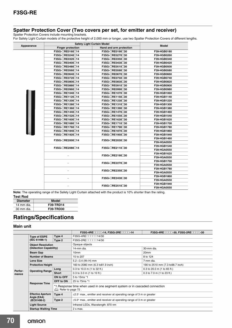
F3SG-RE
70
Spatter Protection Cover (Two covers per set, for emitter and receiver)Spatter Protection Covers include mounting brackets. For Safety Light Curtain models of the protective height of 2,000 mm or longer, use two Spatter Protection Covers of different lengths.
Note: The operating range of the Safety Light Curtain attached with the product is 10% shorter than the rating.
Test Rod
Ratings/Specifications
Main unit
AppearanceSafety Light Curtain Model
ModelFinger protection Hand and arm protection
F3SG-@RE0160@14 F3SG-@RE0190@30 F39-HGB0180F3SG-@RE0240@14 F3SG-@RE0270@30 F39-HGB0260F3SG-@RE0320@14 F3SG-@RE0350@30 F39-HGB0340F3SG-@RE0400@14 F3SG-@RE0430@30 F39-HGB0420F3SG-@RE0480@14 F3SG-@RE0510@30 F39-HGB0500F3SG-@RE0560@14 F3SG-@RE0590@30 F39-HGB0580F3SG-@RE0640@14 F3SG-@RE0670@30 F39-HGB0660F3SG-@RE0720@14 F3SG-@RE0750@30 F39-HGB0740F3SG-@RE0800@14 F3SG-@RE0830@30 F39-HGB0820F3SG-@RE0880@14 F3SG-@RE0910@30 F39-HGB0900F3SG-@RE0960@14 F3SG-@RE0990@30 F39-HGB0980F3SG-@RE1040@14 F3SG-@RE1070@30 F39-HGB1060F3SG-@RE1120@14 F3SG-@RE1150@30 F39-HGB1140F3SG-@RE1200@14 F3SG-@RE1230@30 F39-HGB1220F3SG-@RE1280@14 F3SG-@RE1310@30 F39-HGB1300F3SG-@RE1360@14 F3SG-@RE1390@30 F39-HGB1380F3SG-@RE1440@14 F3SG-@RE1470@30 F39-HGB1460F3SG-@RE1520@14 F3SG-@RE1550@30 F39-HGB1540F3SG-@RE1600@14 F3SG-@RE1630@30 F39-HGB1620F3SG-@RE1680@14 F3SG-@RE1710@30 F39-HGB1700F3SG-@RE1760@14 F3SG-@RE1790@30 F39-HGB1780F3SG-@RE1840@14 F3SG-@RE1870@30 F39-HGB1860F3SG-@RE1920@14 F3SG-@RE1950@30 F39-HGB1940
F3SG-@RE2000@14 F3SG-@RE2030@30F39-HGB1460F39-HGA0550
F3SG-@RE2080@14 F3SG-@RE2110@30F39-HGB1540F39-HGA0550
− F3SG-@RE2190@30F39-HGB1620F39-HGA0550
− F3SG-@RE2270@30F39-HGB1700F39-HGA0550
− F3SG-@RE2350@30F39-HGB1780F39-HGA0550
− F3SG-@RE2430@30F39-HGB1860F39-HGA0550
− F3SG-@RE2510@30F39-HGB1940F39-HGA0550
Diameter Model14 mm dia. F39-TRD1430 mm dia. F39-TRD30
F3SG-4RE@@@@-14, F3SG-2RE@@@@-14 F3SG-4RE@@@@-30, F3SG-2RE@@@@-30
Perfor-mance
Type of ESPE(IEC 61496-1)
Type 4 F3SG-4RE@@@@@14/30
Type 2 F3SG-2RE@@@@@14/30
Object Resolution(Detection Capability)
Opaque objects
14-mm dia. 30-mm dia.
Beam Gap 10mm 20mm
Number of Beams 15 to 207 8 to 124
Lens Size 5.2 ×3.4 (W×H) mm 7-mm dia.
Protective Height 160 to 2080 mm (6.3 to81.9 inch) 190 to 2510 mm (7.3 to98.7 inch)
Operating RangeLong 0.3 to 10.0 m (1 to 32 ft.) 0.3 to 20.0 m (1 to 65 ft.)
Short 0.3 to 3.0 m (1 to 10 ft.) 0.3 to 7.0 m (1 to 23 ft.)
Response Time
ON to OFF 5 to 15ms *1
OFF to ON 25 to 75ms *1
*1.Response time when used in one segment system or in cascaded connection Refer to page 72 .
Effective ApertureAngle (EAA) (IEC61496-2)
Type 4 ±2.5° max., emitter and receiver at operating range of 3 m or greater
Type 2 ±5.0° max., emitter and receiver at operating range of 3 m or greater
Light Source Infrared LEDs, Wavelength: 870 nm
Startup Waiting Time 2 s max.

F3SG-RE
71
Electricall
Power Supply Voltage (Vs) SELV/PELV 24 VDC±20% (ripple p-p 10% max.)
Current Consumption Refer to page 72
Safety Outputs (OSSD)
F3SG-@RE@@@@P@@: Two PNP transistor outputsF3SG-@RE@@@@N@@: Two NPN transistor outputs
Load current of 300 mA max., Residual voltage of 2 V max. (except for voltage drop due to cableextension), Capacitive load of 1 μF max., Inductive load of 2.2 H max. *1Leakage current of 1 mA max. (PNP), 2 mA max. (NPN) *2*1.The load inductance is the maximum value when the safety output frequently repeats ON and OFF. When you use the safety output at 4 Hz or less, the usable load inductance becomes larger.*2. These values must be taken into consideration when connecting elements including a capacitive load such as a capacitor.
Output OperationMode
SafetyOutput Light-ON (Safety output is enabled when the receiver receives an emitting signal.)
Input Voltage
ON Voltage Operating Range Select Input:Long: 9 V to Vs (sink current 3 mA max.) *Short: 0 to 3 V (source current 3 mA max.)OFF Voltage
*The Vs indicates a supply voltage value in your environment.Overvoltage Category (IEC60664-1) II
Indicators Refer to page 73
Protective Circuit Output short protection, Power supply reverse polarity protection
Insulation Resistance 20 MΩ or higher (500 VDC megger)
Dielectric Strength 1,000 VAC, 50/60 Hz (1 min)
Functional Test Function Self-test (at power-on, and during operation)
Environ-mental
AmbientTemperature
Operating -10 to 55°C (14 to 131°F) (non-icing)
Storage -25 to 70°C (-13 to 158°F)
AmbientHumidity
Operating 35% to 85% (non-condensing)
Storage 35% to 95%
Ambient Illuminance Incandescent lamp: 3,000 Ix max. on receiver surfaceSunlight: 10,000 Ix max. on receiver surface
Degree of Protection (IEC 60529) IP65 and IP67
Vibration Resistance (IEC 61496-1) 10 to 55 Hz, Multiple amplitude of 0.7 mm, 20 sweeps for all 3 axes
Shock Resistance (IEC 61496-1) 100 m/s2, 1000 shocks for all 3 axes
Pollution Degree (IEC 60664-1) Pollution Degree 3
Connec-tions
Power cable
Type of Connection M12 connectors: 4-pin, IP67 rated when mated,Cables prewired to the sensors
Number of Wires Emitter: 4, Receiver: 4
Cable Length 0.3 m
Cable Diameter 6 mmMinimum Bend-ing Radius R5 mm
Extension cable- Single-endedcable- Double-endedcable
Type of Connection
Use the XS5@-D42@ series cables.
Number of Wires
Cable Length
Cable Diameter
Minimum Bend-ing Radius
Extension of Power Cable 100 m max.
Material
Material
Housing: AluminumCap: PBTFront window: PMMACable: Oil resistant PVCMounting Bracket: ZDC2FE plate: SUS
Weight (packaged) Refer to page 72.
Included Accessories
Safety Precautions, Quick Installation Manual, Standard Fixed Bracket*1, Troubleshooting GuideSticker*1. The quantity of Standard Fixed Brackets included varies depending on the protective height.
[F3SG-@RE@@@@@14]- Protective height of 0160 to 1200: 2 sets- Protective height of 1280 to 2080: 3 sets[F3SG-@RE@@@@@30]- Protective height of 0190 to 1230: 2 sets- Protective height of 1310 to 2270: 3 sets- Protective height of 2350 to 2510: 4 sets
Conformity
Conforming standards Refer to page 24
Performance Level(PL)/Safety category
Type 4 PL e/Category 4 (EN ISO 13849-1:2008)
Type 2 PL c/Category 2 (EN ISO 13849-1:2008)
PFHd 9.1 × 10⁻⁹ (IEC 61508)
Proof test interval TM Every 20 years (IEC 61508)
SFF 99% (IEC 61508)
HFT 1 (IEC 61508)
Classification Type B (IEC 61508-2)
F3SG-4RE@@@@-14, F3SG-2RE@@@@-14 F3SG-4RE@@@@-30, F3SG-2RE@@@@-30

F3SG-RE
72
List of Models/Response Time/Current Consumption/WeightF3SG-@RE@@@@@-14
* The weight includes an emitter, a receiver and included brackets in a product package.
F3SG-@RE@@@@@30
* The weight includes an emitter, a receiver and included brackets in a product package.
ModelNumber
ofBeams
ProtectiveHeight[mm]
Response Time[ms] Current Consumption[mA]Weight[kg] *ON→OFF
OFF(Synchronized)
→ON
OFF (Notsynchronized)
→ONEmitter Receiver
F3SG-@RE0160@14 15 160 5 25 125 45 50 1.7
F3SG-@RE0240@14 23 240 5 25 125 55 55 1.9
F3SG-@RE0320@14 31 320 7 35 135 55 55 2.1
F3SG-@RE0400@14 39 400 7 35 135 65 60 2.6
F3SG-@RE0480@14 47 480 7 35 135 70 60 2.8
F3SG-@RE0560@14 55 560 7 35 135 80 60 3.1
F3SG-@RE0640@14 63 640 7 35 135 85 65 3.3
F3SG-@RE0720@14 71 720 9 45 145 80 65 3.8
F3SG-@RE0800@14 79 800 9 45 145 85 70 4.0
F3SG-@RE0880@14 87 880 9 45 145 90 70 4.2
F3SG-@RE0960@14 95 960 9 45 145 95 75 4.4
F3SG-@RE1040@14 103 1040 9 45 145 100 75 4.6
F3SG-@RE1120@14 111 1120 11 55 155 90 75 4.7
F3SG-@RE1200@14 119 1200 11 55 155 95 80 4.9
F3SG-@RE1280@14 127 1280 11 55 155 100 80 5.1
F3SG-@RE1360@14 135 1360 11 55 155 105 85 5.6
F3SG-@RE1440@14 143 1440 11 55 155 110 85 5.7
F3SG-@RE1520@14 151 1520 13 65 165 100 90 5.9
F3SG-@RE1600@14 159 1600 13 65 165 105 90 6.5
F3SG-@RE1680@14 167 1680 13 65 165 110 95 6.7
F3SG-@RE1760@14 175 1760 13 65 165 115 95 6.9
F3SG-@RE1840@14 183 1840 13 65 165 115 95 7.1
F3SG-@RE1920@14 191 1920 15 75 175 110 100 7.3
F3SG-@RE2000@14 199 2000 15 75 175 115 100 7.4
F3SG-@RE2080@14 207 2080 15 75 175 115 105 8.0
ModelNumber
ofBeams
ProtectiveHeight[mm]
Response Time[ms] Current Consumption[mA]Weight[kg] *ON→OFF
OFF(Synchronized)
→ON
OFF (Notsynchronized)
→ONEmitter Receiver
F3SG-@RE0190@30 8 190 5 25 125 40 50 1.7
F3SG-@RE0270@30 12 270 5 25 125 45 50 1.9
F3SG-@RE0350@30 16 350 5 25 125 50 50 2.1
F3SG-@RE0430@30 20 430 5 25 125 55 55 2.6
F3SG-@RE0510@30 24 510 5 25 125 60 55 2.8
F3SG-@RE0590@30 28 590 7 35 135 50 55 3.0
F3SG-@RE0670@30 32 670 7 35 135 55 55 3.2
F3SG-@RE0750@30 36 750 7 35 135 60 60 3.8
F3SG-@RE0830@30 40 830 7 35 135 65 60 4.0
F3SG-@RE0910@30 44 910 7 35 135 65 60 4.2
F3SG-@RE0990@30 48 990 7 35 135 70 60 4.4
F3SG-@RE1070@30 52 1070 7 35 135 75 60 4.5
F3SG-@RE1150@30 56 1150 7 35 135 80 65 4.7
F3SG-@RE1230@30 60 1230 7 35 135 85 65 4.9
F3SG-@RE1310@30 64 1310 7 35 135 85 65 5.1
F3SG-@RE1390@30 68 1390 9 45 145 75 65 5.5
F3SG-@RE1470@30 72 1470 9 45 145 80 65 5.7
F3SG-@RE1550@30 76 1550 9 45 145 80 70 5.9
F3SG-@RE1630@30 80 1630 9 45 145 85 70 6.4
F3SG-@RE1710@30 84 1710 9 45 145 85 70 6.6
F3SG-@RE1790@30 88 1790 9 45 145 90 70 6.8
F3SG-@RE1870@30 92 1870 9 45 145 95 75 7.0
F3SG-@RE1950@30 96 1950 9 45 145 95 75 7.2
F3SG-@RE2030@30 100 2030 9 45 145 100 75 7.3
F3SG-@RE2110@30 104 2110 9 45 145 100 75 7.9
F3SG-@RE2190@30 108 2190 11 55 155 90 75 8.1
F3SG-@RE2270@30 112 2270 11 55 155 95 80 8.2
F3SG-@RE2350@30 116 2350 11 55 155 95 80 8.7
F3SG-@RE2430@30 120 2430 11 55 155 95 80 8.8
F3SG-@RE2510@30 124 2510 11 55 155 100 80 9.0

F3SG-RE
73
LED Indicator StatusEmitter
Receiver
Name of Indicator Color Illuminated Blinking
Operating range LONG Green Long range mode is selected Lockout state due to Operating range selection setting error
Power POWER Green Power is ON. Error due to noise
Lockout LOCKOUT Red − Lockout state due to error in emitter
Name of Indicator Color Illuminated Blinking
Top-beam-state TOP Blue The top beam is unblocked −
Internal error INTERNAL Red − Lockout state due to Internal error, or error due to abnormal power supply or noise
Lockout LOCKOUT Red − Lockout state due to error in receiver
Stable-state STB Green Incident light level is 170% or higher of ON threshold Safety output is instantaneously turned OFF due to ambi-ent light or vibration
ON/OFF ON/OFFGreen Safety output is in ON state −
Red Safety output is in OFF state Lockout state due to Safety Output error, or error due to ab-normal power supply or noise
Communication COM GreenSynchronization between emitter and receiver is main-tained
Lockout state due to Communication error, or error due to abnormal power supply or noise
Bottom-beam-state BTM Blue The bottom beam is unblocked −

F3SG-RE
74
Connections (Basic Wiring Diagram)
Short Mode
Note: Functional earth connection is unnecessary when you use the F3SG-R in a general industrial environment where noise control or stable power supply is considered. However, when you use the F3SG-R in an environment where there may be excessive noise from surroundings or stable power supply may be interfered, it is recommended the F3SG-R be connected to functional earth.The wiring examples in later examples do not indicate functional earth. To use functional earth, wire an earth cable according to the example above. Refer to Safety Light Curtain F3SG-R Series User's Manual for more information.
Long Mode
+24 V
0 V
OS
SD
1 : B
lack
OS
SD
2 : W
hite
Ope
ratin
g R
ange
Sel
ect I
nput
: W
hite
24 V
DC
: B
row
n
N.C
. : B
lack
24 V
DC
: B
row
n
0 V
: B
lue
Rec
eive
r
Em
itter
0 V
: B
lue
DCPower Supply
Safety Controller *1*2
IN1 IN2
UnblockedBlocked
OSSD
Functional Earth
Beam state
*1.Refer to page 49 for more information.*2.The safety controller and the F3SG-R must share the power supply or be connected to the common
terminal of the power supply.
IN1 IN2
+24 V
0 V
OS
SD
1 : B
lack
OS
SD
2 : W
hite
Ope
ratin
g R
ange
Sel
ect I
nput
: W
hite
24 V
DC
: B
row
n
Not
use
d : B
lack
24 V
DC
: B
row
n
0 V
: B
lue
Rec
eive
r
Em
itter
0 V
: B
lue
DCPower Supply
Safety Controller *1*2
UnblockedBlocked
OSSD
Beam state
*1.Refer to page 49 for more information.*2.The safety controller and the F3SG-R must share the power supply or be connected to the common
terminal of the power supply.

F3SG-RE
75
Standalone F3SG-RE with Y-Joint Plug/Socket Connector
Note: When using the reduced wiring connector system F39-GCNY1, the Operating Range Selection is fixed to Long Mode.
Connectable Safety Control UnitsThe F3SG-RE with PNP output can be connected to the safety control units listed in the table below.
Connectable Safety Control Units (PNP output)
G9SA-301G9SA-321G9SA-501G9SB-200-BG9SB-200-DG9SB-301-BG9SB-301-DG9SE-201G9SE-401G9SE-221-T@
G9SX-AD322-TG9SX-ADA222-TG9SX-BC202G9SX-GS226-T15
G9SP-N10SG9SP-N10DG9SP-N20SNE0A-SCPU01NE1A-SCPU01NE1A-SCPU02DST1-ID12SL-1DST1-MD16SL-1DST1-MRD08SL-1NX-SIH400NX-SID800F3SP-T01
0 VD
C: B
lue
OS
SD
1: B
lack
OS
SD
2: W
hite
24 V
DC
: Bro
wn
+24V DC
0V
XS5W-D42�-�81-�
F39-GCNY1
XS5F-D42�-�80-�
IN1 IN2
Safety Controller *1*2
Power supply
UnblockedBlocked
OSSD
Beam state
*1.Refer to the following list "Connectable Safety Control Units" onthis page.
*2.The safety controller and the F3SG-R must share the powersupply or be connected to the common terminal of the powersupply.

F3SG-RE
76
Input/Output CircuitPNP Output
NPN Output
1
4
3
2
+24 V1
2
4
3
0 V
Operating Range Select Input circuit
Brown
Black Not connected
White
Blue
Brown
White OSSD 2
Black OSSD 1
Blue
Indicator
EmitterMain Circuit
ReceiverMain Circuit 2
ReceiverMain Circuit 1
Indicator
Load
Load
Operating Range Select Input
1
4
3
2
+24 V1
2
4
3
0 V
Brown
Black Not connected
White
Blue
Brown
White OSSD 2
Black OSSD 1
Blue
Indicator
EmitterMain Circuit
ReceiverMain Circuit 2
ReceiverMain Circuit 1
Indicator
Load
Load
Operating Range Select Input circuit
Operating Range Select Input

F3SG-RE
77
Input Circuit Diagram by FunctionThe input circuit diagrams of by function are shown below.
PNP Output
NPN Output
Emitter Main Circuit
+24 VDC
0 VDC
5 V
Short circuit current:3 mA
<Input circuit (Operating Range Select Input)>
Emitter Main Circuit
+24 VDC
0 VDC
5 V
Short circuit current:3 mA
<Input circuit (Operating Range Select Input)>

F3SG-RE
78
Dimensions (Unit: mm)
Mounted with Standard Fixed Brackets (F39-LGF)Backside Mounting
* Mounting an emitter or receiver with one bracket is possible for the models of protective height of 0160 to 0270. In this case, locate this bracket at half the Dimension A (or at the center of the sensor length).
F3SG-4RE@@@@@30 Series
Dimension A C1
Dimension C1 4-digit number of the type name(Protective height)
Dimension D C1-50
Dimension P 20
Protective height(C1)
Number of Standard Fixed Brackets Dimension F
0190 to 1230 2 * 1000 mm max.
1310 to 2270 3 1000 mm max.
2350 to 2510 4 1000 mm max.
F3SG-4RE@@@@@14 Series
Dimension A C2+30
Dimension C2 4-digit number of the type name(Protective height)
Dimension D C2-20
Dimension P 10
Protective height(C2)
Number of Standard Fixed Brackets Dimension F
0160 to 1200 2 * 1000 mm max.
1280 to 2080 3 1000 mm max.
P
51
24.85
F
D C2
(Pro
tect
ive
heig
ht fo
r 14
mm
)
FA
150
max
150
max
150
max
150
max
25 15
24.85
6.4
9.2
51
66
35
C1
(Pro
tect
ive
heig
ht fo
r 30
mm
)A
51
2-M5 or M6
2-M5 or M6
3540
Standard Fixed Bracket
Standard Fixed Bracket
(F39-LGF)
(F39-LGF)
50.3
5
< Screw: M5 or M6 >

F3SG-RE
79
Side Mounting
* Mounting an emitter or receiver with one bracket is possible for the models of protective height of 0160 to 0270. In this case, locate this bracket at half the Dimension A (or at the center of the sensor length).
Standard Fixed Bracket(F39-LGF)
F3SG-4RE@@@@@30 Series
Dimension A C1
Dimension C1 4-digit number of the type name (Protective height)
Dimension D C1-50
Dimension P 20
Protective height(C1)
Number of Standard Fixed Brackets Dimension F
0190 to 1230 2 * 1000 mm max.
1310 to 2270 3 1000 mm max.
2350 to 2510 4 1000 mm max.
F3SG-4RE@@@@@14 Series
Dimension A C2+30
Dimension C2 4-digit number of the type name (Protective height)
Dimension D C2-20
Dimension P 10
Protective height(C2)
Number of Standard Fixed Brackets Dimension F
0160 to 1200 2 * 1000 mm max.1280 to 2080 3 1000 mm max.
P
D
C2
(Pro
tect
ive
heig
ht fo
r 14
mm
)25 15
3540
C1
(Pro
tect
ive
heig
ht fo
r 30
mm
)A
Standard Fixed Bracket
Standard Fixed Bracket
(F39-LGF)
(F39-LGF)
50.3
5
51
F
42.35
A15
0 m
ax15
0 m
axF
150
max
150
max
5151
9.26.
4
66
35
2-M5 or M6
2-M5 or M6
< Screw: M5 or M6 >
51
8
(23.1)
(25.8)
9.2
66
6.4
32.1
36
Material: ZDC2

F3SG-RE
80
Mounted with Standard Fixed Brackets (F39-LGA)Backside Mounting
* Mounting an emitter or receiver with one bracket is possible for the models of protective height of 0160 to 0270. In this case, locate this bracket at half the Dimension A (or at the center of the sensor length).
F3SG-4RE@@@@@30 Series
Dimension A C1
Dimension C1 4-digit number of the type name (Protective height)
Dimension D C1-50
Dimension P 20
Protective height(C1)
Number of Standard Adjustable Brackets Dimension F
0190 to 1230 2 * 1000 mm max.
1310 to 2270 3 1000 mm max.
2350 to 2510 4 1000 mm max.
F3SG-4RE@@@@@14 Series
Dimension A C2+30
Dimension C2 4-digit number of the type name (Protective height)
Dimension D C2-20
Dimension P 10
Protective height(C2)
Number of Standard Adjustable Brackets Dimension F
0160 to 1200 2 * 1000 mm max.
1280 to 2080 3 1000 mm max.
P
72
24.85
F
D
C2
(Pro
tect
ive
heig
ht fo
r 14
mm
)
FA
150
max
150
max
150
max
150
max
25 15
24.859.2
6.4
72
84
35
C1
(Pro
tect
ive
heig
ht fo
r 30
mm
)A
722-M5 or M6
2-M5 or M6
3548.6
Standard AdjustableBracket
Standard AdjustableBracket
(F39-LGA)
(F39-LGA)
50.3
5
< Screw: M5 or M6 >

F3SG-RE
81
Side Mounting
* Mounting an emitter or receiver with one bracket is possible for the models of protective height of 0160 to 0270. In this case, locate this bracket at half the Dimension A (or at the center of the sensor length).
Standard Fixed Bracket (F39-LGA)
F3SG-4RE@@@@@30 Series
Dimension A C1
Dimension C1 4-digit number of the type name (Protective height)
Dimension D C1-50
Dimension P 20
Protective height(C1)
Number of Standard Adjustable Brackets Dimension F
0190 to 1230 2 * 1000 mm max.
1310 to 2270 3 1000 mm max.
2350 to 2510 4 1000 mm max.
F3SG-4RE@@@@@14 Series
Dimension A C2+30
Dimension C2 4-digit number of the type name (Protective height)
Dimension D C2-20
Dimension P 10
Protective height(C2)
Number of Standard Adjustable Brackets Dimension F
0160 to 1200 2 * 1000 mm max.
1280 to 2080 3 1000 mm max.
PD C
2 (P
rote
ctiv
e he
ight
for
14 m
m)
25 15
3548.6
C1
(Pro
tect
ive
heig
ht fo
r 30
mm
)A
Standard Adjustable Bracket
Standard Adjustable Bracket
(F39-LGA)
(F39-LGA)
50.3
5
72
F42.35
A
150
max
150
max
F
150
max
150
max
6.4
9.2
7272
84
35
2-M5 or M6
2-M5 or M6
< Screw: M5 or M6 >
8
72
42
45.1
84
9.2
6.4
32.9
(31.8)
(34.5)
Material: ZDC2, Fluorochemical lubricant oil
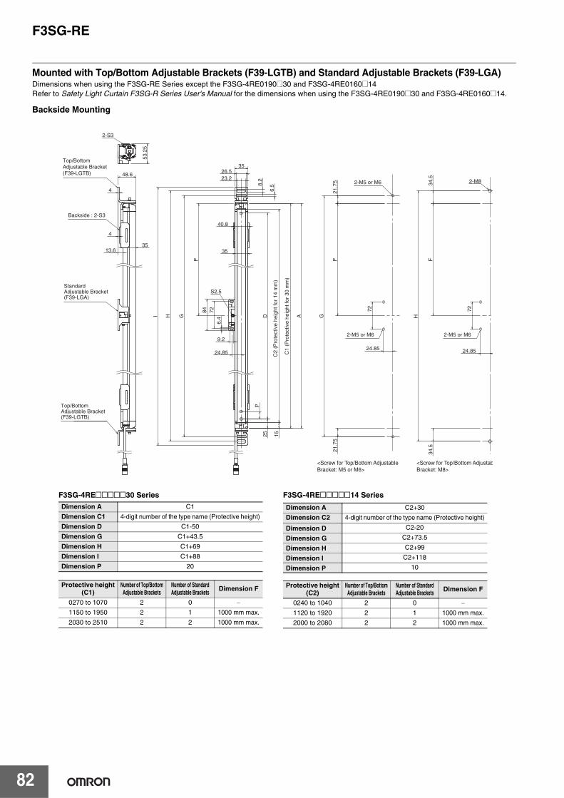
F3SG-RE
82
Mounted with Top/Bottom Adjustable Brackets (F39-LGTB) and Standard Adjustable Brackets (F39-LGA)Dimensions when using the F3SG-RE Series except the F3SG-4RE0190@30 and F3SG-4RE0160@14Refer to Safety Light Curtain F3SG-R Series User's Manual for the dimensions when using the F3SG-4RE0190@30 and F3SG-4RE0160@14.
Backside Mounting
Standard Adjustable Bracket(F39-LGA)
Top/Bottom Adjustable Bracket(F39-LGTB)
Top/Bottom Adjustable Bracket(F39-LGTB)
Backside : 2-S3
2-M5 or M6
2-M5 or M6
2-M5 or M6
C1
(Pro
tect
ive
heig
ht fo
r 30
mm
)
C2
(Pro
tect
ive
heig
ht fo
r 14
mm
)
<Screw for Top/Bottom Adjustable Bracket: M5 or M6>
<Screw for Top/Bottom AdjustabBracket: M8>
48.6
35 13.6
4
4
2-S3
53.
25
2-M8
S2.5
84
G
35
40.8
A
H
I
26.5
35
23.2
6.5
8.2
9.2
72
6.4
G
P
15
25
F
21.
75
F
F
H
34.
5 3
4.5
21.
75
D
24.85
72
24.85
72
24.85
F3SG-4RE@@@@@30 Series
Dimension A C1
Dimension C1 4-digit number of the type name (Protective height)
Dimension D C1-50
Dimension G C1+43.5
Dimension H C1+69
Dimension I C1+88
Dimension P 20
Protective height(C1)
Number of Top/BottomAdjustable Brackets
Number of Standard Adjustable Brackets Dimension F
0270 to 1070 2 0 −1150 to 1950 2 1 1000 mm max.
2030 to 2510 2 2 1000 mm max.
F3SG-4RE@@@@@14 Series
Dimension A C2+30
Dimension C2 4-digit number of the type name (Protective height)
Dimension D C2-20
Dimension G C2+73.5
Dimension H C2+99
Dimension I C2+118
Dimension P 10
Protective height(C2)
Number of Top/BottomAdjustable Brackets
Number of Standard Adjustable Brackets Dimension F
0240 to 1040 2 0 −1120 to 1920 2 1 1000 mm max.
2000 to 2080 2 2 1000 mm max.

F3SG-RE
83
Side Mounting
<Screw for Top/Bottom Adjustable Bracket: M5 or M6>
<Screw for Top/Bottom Adjustable Bracket: M8>
Top/Bottom Adjustable Bracket(F39-LGTB)
Top/Bottom Adjustable Bracket(F39-LGTB)
Standard Adjustable Bracket(F39-LGA)
Backside : 2-S3
2-M5 or M6
2-M5 or M6
2-M5 or M6
C1
(Pro
tect
ive
heig
ht fo
r 30
mm
)
C2
(Pro
tect
ive
heig
ht fo
r 14
mm
)S2.5
35
23.2 26.5
35
6.5
8
.2
G
H
I 84
72
6.4
9.2
2-S3
50.35
2-M8
40.8
35
4
51.65
A
D
P
F
F
F
15
25
H
34.
5 3
4.5
21.
75
21.
75
G 7
2
72
42.35
F3SG-4RE@@@@@30 Series Dimension A C1
Dimension C1 4-digit number of the type name (Protective height)
Dimension D C1-50
Dimension G C1+43.5
Dimension H C1+69
Dimension I C1+88
Dimension P 20
Protective height(C1)
Number of Top/BottomAdjustable Brackets
Number of Standard Adjustable Brackets Dimension F
0270 to 1070 2 0 −1150 to 1950 2 1 1000 mm max.
2030 to 2510 2 2 1000 mm max.
F3SG-4RE@@@@@14 Series Dimension A C2+30
Dimension C2 4-digit number of the type name (Protective height)
Dimension D C2-20
Dimension G C2+73.5
Dimension H C2+99
Dimension I C2+118
Dimension P 10
Protective height(C2)
Number of Top/BottomAdjustable Brackets
Number of Standard Adjustable Brackets Dimension F
0240 to 1040 2 0 −1120 to 1920 2 1 1000 mm max.
2000 to 2080 2 2 1000 mm max.
Material: SUS304
Top/Bottom Adjustable Bracket(F39-LGTB)
4
31
4
48.25
5
26.5
23.2 8.2
6.5
9.5
22.2
5
44
45
1867
23.5
26
20
161
35
40.8
Top/Bottom Bracket (1)
Top/Bottom Bracket (2)
Top/Bottom Bracket (3)
Screw (2)
Screw(1)
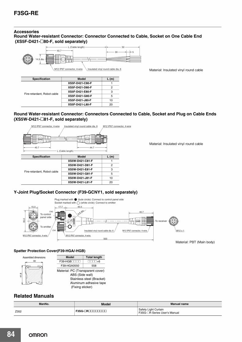
F3SG-RE
84
AccessoriesRound Water-resistant Connector: Connector Connected to Cable, Socket on One Cable End (XS5F-D421-@80-F, sold separately)
Round Water-resistant Connector: Connectors Connected to Cable, Socket and Plug on Cable Ends (XS5W-D421-@81-F, sold separately)
Y-Joint Plug/Socket Connector (F39-GCNY1, sold separately)
Spatter Protection Cover(F39-HGA/-HGB)
Related ManualsManNo. Model Manual name
Z352 F3SG-@R@@@@@@@@ Safety Light CurtainF3SG-@R Series User's Manual
Specification Model L (m)
Fire-retardant, Robot cable
XS5F-D421-C80-F 1
XS5F-D421-D80-F 2
XS5F-D421-E80-F 3
XS5F-D421-G80-F 5
XS5F-D421-J80-F 10
XS5F-D421-L80-F 20
40.7
L (Cable length)
M12 IP67 connector, 4-wire Insulated vinyl round cable dia. 6
50
30 5
14.9 dia.
Material: Insulated vinyl round cable
Specification Model L (m)
Fire-retardant, Robot cable
XS5W-D421-C81-F 1
XS5W-D421-D81-F 2
XS5W-D421-E81-F 3
XS5W-D421-G81-F 5
XS5W-D421-J81-F 10
XS5W-D421-L81-F 20
40.7
L (Cable length)
M12 IP67 connector, 4-wire Insulated vinyl round cable dia. 6 M12 IP67 connector, 4-wire
44.7
Material: Insulated vinyl round cable
Plug marked with (bule circle): Connect to control panel sideSocket marked with (white circle): Connect to emitter
CN1
CN2
4.6 dia.
17.7 45.5
M12 x 1
40.7
35.0
15.0
500
To receiver
To control panel side
To emitter
M12 IP67 connector, 4-wire M12 IP67 connector, 4-wire
Insulated vinyl round cable dia. 6 M12 IP67 connector, 4-wire
Material: PBT (Main body)
40
41.8
Assembled dimensions
Material: PC (Transparent cover)ABS (Side wall)Stainless steel (Bracket)Aluminum adhesive tape (Fixing sticker)
Model Total length
F39-HGB@@@@ @@@@+6
F39-HGA0550 558

85
Smart Muting ActuatorF3W-MA
Integrated muting sensor based on multi-beam photoelectric sensor• A muting system can be configured easily in
combination with the safety light curtain.• Muting functions can be stably performed even
when workpieces with holes pass.
Ordering InformationSmart Muting Actuator
Note: Use with the PNP output model safety light curtain.
Accessories (Sold separately)Single-ended Connector Cable
Double-en1ded Cable
Appearance Beam Gap between Muting Trigger Beams output Number of
Beams Model
100 mm
PNP output
8 F3W-MA0100P
300 mm 20 F3W-MA0300P
Appearance Type Cable length Specifications Model
M12 connector (5-pin), 5 wiresColor: Gray
3 m F39-JG3A-L7 m F39-JG7A-L
10 m F39-JG10A-L15 m F39-JG15A-L20 m F39-JG20A-L
For receiverM12 connector (8-pin), 8 wiresColor: Black
3 m F39-JG3A-D
7 m F39-JG7A-D
10 m F39-JG10A-D
15 m F39-JG15A-D
20 m F39-JG20A-D
Appearance Type Cable length Specifications Model
M12 connector (5-pin) on both endsColor: Gray
0.5 m F39-JGR5B-L
1 m F39-JG1B-L
3 m F39-JG3B-L
5 m F39-JG5B-L
7 m F39-JG7B-L
10 m F39-JG10B-L
15 m F39-JG15B-L
20 m F39-JG20B-L
M12 connector (8-pin) on both endsColor: Black
0.5 m F39-JGR5B-D
1 m F39-JG1B-D
3 m F39-JG3B-D
5 m F39-JG5B-D
7 m F39-JG7B-D
10 m F39-JG10B-D
15 m F39-JG15B-D
20 m F39-JG20B-D
53
21
4
Female
12345
+24 VDCCFG In0 VDCCOM+COM-
BrownBlackBlueWhiteYellow
5
843
2176
Female
2
7
56
1+24 VDC
0 VDC
Muting Output AMuting Output B
Mute Enable / CFG In / ResetBrown
Blue
BlackWhite
Yellow
8 CFG Out Red
3 COM+ Gray4 COM- Pink
BrownBlueBlackWhiteYellow
13245
53
21
4
BrownBlueBlackWhiteYellow
13245
Female
54
12
3
Male
Connected to Power Cable or Double-Ended Cable
Connected to Single-Ended Cable, Double-Ended cable
BrownBlueBlackWhiteYellowRedGrayPink
BlueBlackWhiteYellowRedGrayPink
27561834
Brown
5
84
321
7
65
86
712
3
4
27561834
Connected to Power Cable or Double-Ended Cable
Connected to Single-Ended Cable, Double-Ended cable
Female Male

F3W-MA
86
4-Joint Plug/Socket Connector
Used for reduced wiring for connecting F3W-MA with F3SG-RA.
Appearance Type Specifications Model
For emitterM12 connectors.Used for reduced wiring.
F39-GCN4-L
For receiver(PNP output)M12 connectors.Used for reduced wiring.
F39-GCN4-D
Includes one each of F39-GCN4-L and F39-GCN4-D
− F39-GCN4
Water-resistive Cover for 4-Joint Plug/Socket Connector
Water-resistive cover for an F39-GCN4-L/-D 4-Joint Plug/Socket Connector. You canuse this when the MA2 connector part is not used.
Material: PBT IP67 rated when attached. Smart click mechanism.
XS5Z-11
Dust Cover for 4-Joint Plug/Socket Connector
Dust cover for an F39-GCN4-L/-D 4-Joint Plug/Socket Connector. You can use this when the MA2 connector part is not used.
Material: Rubber/black This cover does not ensure IP67 degree of protection.XS2Z-14: Attach to a pin block inside the M12 female screw.XS2Z-15: Attach to a M12 female screw.When attaching the cover to the connector, press the cover onto the connector until the connector is fully inserted into the cover.
XS2Z-14
XS2Z-15
Single-ended Connector CableF39-JG@A-L (Gray)
4-joint plug/Socket ConnectorF39-GCN4-L
F3SG-RAEmitter
F3W-MA Emitter(Secondary)
F3W-MA Emitter(Primary)
Single-ended Connector CableF39-JG@A-D (Black)
4-joint plug/Socket ConnectorF39-GCN4-D
F3W-MA Receiver(Secondary)
F3W-MA Receiver(Primary)
F3SG-RAReceiver

F3W-MA
87
Sensor Mounting Brackets
Note: When mounting an F3W-MA0300P in the L-shaped configuration, the shock resistance becomes as follows.Shock resistance: 50 m/s2, 1000 shocks for all 3 axesFor mounting an F3W-MA0300P under a shock environment exceeding this, the F3W-MA Bracket cannot be used. Use a Standard Adjustable Bracket (F39-LGA).
* When using F39-LGMA@, there are some restrictions on the brackets to mount the F3SG-RA. This bracket is not usable together with F39-LGF. When using together with F39-LGA, the F3SG-RA must be 270 mm or longer. When using together with F39- LGTB, the F3SG-RA must be 400 mm or longer. An extra F39-LGA is required for reinforcement, depending on the mounting position of the F39-LGMA@. Refer to "Dimensions" on page 100 for details.
Appearance Specification Application Remarks Model
Standard Fixed Bracket
Bracket to mount the F3W-MA.Side mounting and backside mounting possible.
Two brackets per set F39-LGF
Standard Adjustable Bracket
Bracket to mount the F3W-MA.Beam alignment after mounting possible.The angle adjustment range is ±15°.Side mounting and backside mounting possible.
Two brackets per set F39-LGA
F3W-MA Bracket
Bracket to fix the F3W-MA to the F3SG-RA.F39-LGMAL: L-shaped configurationF39-LGMAT: T-shaped configurationBeam alignment after mounting possible.When using the F3W-MA Bracket, it is nec-essary to add an extra Standard Adjust-able Bracket (F39-LGA) to the F3SG-RA. * Please also purchase Standard Adjustable Bracket (F39-LGA).
Two brackets per set
F39-LGMAL
F39-LGMAT

F3W-MA
88
Ratings/Specifications
F3W-MA0100P F3W-MA0300P
Perfor-mance
Beam Gap between Muting Trigger Beams 100mm 300mm
Number of Beams 8 20
Standard Detection Object 30mm
Operating Range
Long 0.3 to 20.0 m (1 to 65 ft.)
Short 0.3 to 7.0 m (1 to 23 ft.)
Response TimeOperation 13 ms max.
Reset 26 ms max. (Synchronized)78 ms max. (Not synchronized)
Effective Aperture Angle ±2.5° max., emitter and receiver at operating range of 3 m or greater
Light Source Infrared LEDs, Wavelength: 870 nm
Startup Waiting Time 2 s max.
Electrical
Power Supply Voltage (Vs) SELV/PELV 24 VDC±20% (ripple p-p 10% max.)
CurrentConsumption
Emitter 35mA 45mA
Receiver 75mA 75mA
Muting OutputsTwo PNP transistor outputs. *Load current of 300 mA max.,Residual voltage of 2 V max. (except for voltage drop due to cable extension)j
* This product is a PNP output model. Use with the PNP output model safety light curtain.
Output Opera-tion Mode
Muting Output A Dark-ON(Muting Output A is enabled when MuteA trigger beam is blocked.)
Muting Output B Dark-ON(Muting Output B is enabled when MuteB trigger beam is blocked.)
Input Voltage
ON Voltage [MuteEnable]Vs to Vs-3 V (sink current 5 mA max.) *
OFF Voltage [Mute Enable]0 to 1/2 Vs, or open *
* The Vs indicates a supply voltage value in your environment.
Indicators Refer to page 89. LED Indicator Status
Protective Circuit Protective Circuit Output short protection, Power supply reverse polarity protection
Insulation Resistance 20 MΩ or higher (500 VDC megger)
Dielectric Strength 1,000 VAC, 50/60 Hz (1 min)
Functional Functions
- Scan Code Selection- Operation Mode Selection (Point to Point Detection/ Chattering and Void SpacePrevention)- Off-Delay- Muting Enable- Muting Trigger Beam Allocation- Operating Range Selection
Environ-mental
AmbientTemperature
Operating -10 to 55°C (13 to 131°F) (non-icing)
Storage -25 to 70°C (-13 to 158°F)
AmbientHumidity
Operating 35% to 85% (non-condensing)
Storage 35% to 95%
Ambient Illuminance Incandescent lamp: 3,000 Ix max. on receiver surfaceSunlight: 10,000 Ix max. on receiver surface
Degree of Protection (IEC 60529) IP65 and IP67
Vibration Resistance (IEC 61496-1) 10 to 55 Hz, Multiple amplitude of 0.7 mm, 20 sweeps for all 3 axes
Shock Resistance (IEC 61496-1) 100 m/s2, 1000 shocks for all 3 axes
Pollution Degree (IEC 60664-1) Pollution Degree 3
Connec-tions Extension of Power Cable 100 m max.
Note: For T-Shaped configuration with COM lines, the length of cable extension is 30m max.
Material Housing: Aluminum, Cap: PBT, Front Window: PMMA, Cable: Oil resistant PVC, FEplate: SUS
Weight (packaged) 1.8 kg max. 2.8 kg max.
Included Accessories Instruction Sheet

F3W-MA
89
LED Indicator StatusShown below are indication statuses of F3W-MA LED indicators when you purchased.Emitter
Receiver
Name of Indicator Color Illuminated Blinking
Operating range LONG Green Long Range mode is selected by DIP Switch. -
Running RUN Green Power is ON. -
Error ERR Red - Error in emitter. Generic error happens.
Name of Indicator Color Illuminated Blinking
Top-beam-state TOP Blue The top beam is unblocked. -
Muting output A MUTE A Green Muting Output A is activated. -
Muting output B MUTE B Green Muting Output B is activated. -
Off-Delay DELAY Yellow Off-Delay function is enabled by DIP Switch. -
Chattering/ Voidspace CHAT Green Chattering and Void Space Prevention mode is se-
lected by DIP Switch. -
Muting Enable MUTEDISABLE Red The Muting Enable function is enabled and Muting
Enable input is turned OFF by DIP Switch. -
Error ERR Red - Error in receiver. Generic error happens.
Stable-state STB Green Incident light level is 170% or higher of ON-threshold -
Running RUN Green Power is ON. -
Communication COM Green Synchronization between emitter and receiver is maintained.
[Primary sensor]- Start-up (for approx. 3 s)- Synchronization between emitterand receiver is lost
Bottom-beamstate BTM Blue The bottom beam is unblocked. -

F3W-MA
90
Wiring ExamplesStandard Muting Mode with F3SG-R (T-Shaped Configuration with COM lines)The following is the example of F3W-MA with Scan Code B, Chattering and Void Space Prevention 1, Off-Delay 100 ms and Muting Enable disabled.
DIP Switch settings *1
: Indicates a switch position.*1.Configure functions with the DIP Switches before wiring. Refer to Smart Muting Actuator F3W-MA Series User's Manual for more information.*2.DIP Switch Bank 2 is not used.
Wiring example
Note: The wiring examples in later pages do not indicate functional earth. To use functional earth, wire an earth cable according to the example above. Refer to Smart Muting Actuator F3W-MA Series User's Manual for more information.
Function DIP-SW1 DIP-SW2 *2
F3W-MA PrimaryReceiver
Scan Code B (factory default setting)
Chattering and Void Space Prevention 1
Off-Delay 100 ms
Muting Enable Disabled (factory default setting)
Emitter Scan Code B (factory default setting) −
F3W-MA Secondary ReceiverEmitter − No setting required No setting required
1 ON 1 ON
2 ON
3 ON2 ON
3 ON
4 ON5 ON
4 ON5 ON
6 ON 6 ON
1 ON
Mut
ing
outp
ut A
: Bla
ck
Mut
ing
outp
ut B
: Whi
te
24 V
DC
: Bro
wn
0 V
DC
: Blu
e
F3W-MA Receiver(Primary)
CF
G O
ut: R
ed
CO
M-:
Pin
k
CO
M+
: Gra
y
Mut
e E
nabl
e: Y
ello
w
F3W-MA Receiver(Secondary)
Mut
ing
outp
ut A
: Bla
ck
Mut
ing
outp
ut B
: Whi
te
CO
M-:
Pin
k
CO
M+
: Gra
y
CF
G O
ut: R
ed
CF
G In
: Yel
low
0 V
DC
: Blu
e
24 V
DC
: Bro
wn
F39-JG@A-D F39-JG@A-DFunctional Earth Functional Earth
24 V
DC
: Bro
wn
0 V
DC
: Blu
e
F3W-MA Emitter(Primary)
CF
G In
*2:
Bla
ck
CO
M-:
Yel
low
CO
M+
: Whi
te
F3W-MA Emitter(Secondary)
CO
M-:
Yel
low
CO
M+
: Whi
te
0 V
DC
: Blu
e
24 V
DC
: Bro
wn
F39-JG@A-L F39-JG@A-LFunctional Earth Functional Earth
F3S
G-R
A E
mitt
er *
1
CF
G In
: Bla
ck
Pow
er S
uppl
y
+24 VDC
0 VDC
Pow
er S
uppl
y
+24 VDC
0 VDC
*1. Signal wiring of the F3W-MA is not required.*2. Do not connect CFG In line to +24 VDC line. Otherwise, F3W-MA enters the error state.
[Emitter]
[Receiver]
F3S
G-R
A R
ecei
ver
MU
TE
B
MU
TE
A

F3W-MA
91
Standard Muting Mode with F3SG-R (T-Shaped Configuration with 4-Joint Connector)The following is the example of F3SG-RA with Scan Code B, External Device Monitoring disabled, Auto Reset mode, PNP output and External Test in 24 V Active, and F3W-MA with Scan Code A, Chattering and Void Space Prevention 1, Off-Delay 100 ms and Muting Enable disabled.
DIP Switch settings*1
: Indicates a switch position.*1.Configure functions with the DIP Switches before wiring. For the DIP Switch of the F3W-MA, refer to Smart Muting Actuator F3W-MA Series User's Manual. For the
DIP Switch of the F3SG-RA, refer to the Safety Light Curtain F3SG-R Series User's Manual. *2.DIP Switch Bank 2 of F3W-MA receiver is not used.
Wiring example
Function DIP-SW1 DIP-SW2
F3SG-RA
Receiver
Scan Code B
EDM Disabled (factory default setting)
Auto Reset (factory default setting)
PNP (factory default setting)
EmitterScan Code B −
External Test: 24 V Active (factory default setting) −
F3W-MA PrimaryReceiver
Scan Code A
Chattering and Void Space Prevention 1
Off-Delay 100 ms
Muting Enable Disabled (factory default setting)
Emitter Scan Code A −
F3W-MA Secondary ReceiverEmitter − No setting required No setting required
1 ON 1 ON
2 ON 2 ON
3 ON 3 ON
4 ON 4 ON
7 ON 7 ON
1 ON
4 ON
1 ON *21 ON
2 ON
3 ON2 ON*23 ON*2
4 ON5 ON
4 ON*25 ON*2
6 ON 6 ON*2
1 ON
S1: Test Switch (Connect the line to 0 V if this switch is not required) INS2: Lockout Reset Switch, Override Switch or Override Cancel SwitchML: Muting lamp
*1. Also used as Override input line.*2. Make sure to connect an override cancel switch to the Reset line when using the override function.
Otherwise the override state may not be released by the override cancel switch, resulting in serious injury.*3. Refer to page 34, Connectable Safety Control Units for more information.*4. The safety controller and the F3SG-R must share the power supply or be connected to the common terminal of the power supply.*5. When connecting to the PLC, the output mode must be changed with the Configuration Tool according to your application.
F3W-MA Receiver(Primary)
F3W-MA Receiver(Secondary)
F39-JG A-D
F3S
G-R
A R
ecei
ver
F3W-MA Emitter(Primary)
F3W-MA Emitter(Secondary)
F39-JG A-L
F3S
G-R
A E
mitt
er
24 V
DC
:B
row
n
OS
SD
2:
Whi
te
OS
SD
1:
Bla
ck
AU
X:
Red
0 V
DC
:B
lue
Res
et:
Yel
low
*1
Mut
ing
Ena
ble:
Gra
y
Not
use
d:P
ink
Not
use
d:Y
ello
w
Not
use
d:W
hite
0 V
DC
:B
lue
24 V
DC
:B
row
n
TE
ST
:B
lack
SafetyController *3 *4
IN1 IN2
+24 VDC
0 VDC
Power Supply
S2S1*2
F39-GCN4-L F39-GCN4-D
PLC *5
IN

F3W-MA
92
Exit-Only Muting Mode with F3SG-R (L-Shaped Configuration)The following is the example of F3W-MA with Scan Code A, Chattering and Void Space Prevention 1, Off-Delay 100 ms and Muting Enable enabled.DIP Switch settings*1
: Indicates a switch position.*1.Configure functions with the DIP Switches before wiring. Refer to Smart Muting Actuator F3W-MA Series User's Manual for more information.*2.DIP Switch Bank 2 is not used.
Wiring example
Function DIP-SW1 DIP-SW2 *2
F3W-MAReceiver
Scan Code A
Chattering and Void Space Prevention 1
Off-Delay 100 ms
Muting Enable Enabled
Emitter Scan Code A −
1 ON 1 ON
2 ON
3 ON2 ON
3 ON
4 ON5 ON
4 ON5 ON
6 ON 6 ON
1 ON
S1: Mute Enable Switch
Mut
ing
outp
ut A
: Bla
ck
Mut
ing
outp
ut B
: Whi
te
24 V
DC
: Bro
wn
0 V
DC
: Blu
e
F3W-MA Receiver
CF
G O
ut: R
ed
CO
M-:
Pin
k
CO
M+
: Gra
y
Mut
e E
nabl
e: Y
ello
w
S1
F39-JG@A-D
F3S
G-R
A R
ecei
ver
24 V
DC
: Bro
wn
0 V
DC
: Blu
e
F3W-MA Emitter
CF
G In
*2:
Bla
ck
CO
M-:
Yel
low
CO
M+
: Whi
te
F39-JG@A-L
F3S
G-R
A E
mitt
er *
1
Pow
er S
uppl
y
+24 VDC
0 VDC
Pow
er S
uppl
y
+24 VDC
0 VDC
*1. Signal wiring of the F3W-MA is not required.*2. Do not connect CFG In line to +24 VDC line. Otherwise, F3W-MA enters the error state.
[Emitter]
[Receiver]
MU
TE
B
MU
TE
A

F3W-MA
93
Exit-Only Muting Mode with F3SG-R (L-Shaped Configuration with 4-Joint Connector)The following is the example of F3SG-RA with Scan Code A, External Device Monitoring disabled, Auto Reset mode, PNP output and External Test in 24 V Active, and F3W-MA with Scan Code B, Chattering and Void Space Prevention 1, Off-Delay 100 ms and Muting Enable enabled.
DIP Switch settings*1
: Indicates a switch position.*1.Configure functions with the DIP Switches before wiring. For the DIP Switch of the F3W-MA, refer to Smart Muting Actuator F3W-MA Series User's Manual. For the
DIP Switch of the F3SG-RA, refer to the Safety Light Curtain F3SG-R Series User's Manual.*2.DIP Switch Bank 2 of F3W-MA receiver is not used.
Wiring example
Function DIP-SW1 DIP-SW2
F3SG-RA
Receiver
Scan Code A (factory default setting)
EDM Disabled (factory default setting)
Auto Reset (factory default setting)
PNP (factory default setting)
EmitterScan Code A (factory default setting) −
External Test: 24 V Active (factory default setting) −
F3W-MAReceiver
Scan Code B (factory default setting)
Chattering and Void Space Prevention 1
Off-Delay 100 ms
Muting Enable Enabled
Emitter Scan Code B (factory default setting) −
1 ON 1 ON
2 ON 2 ON
3 ON 3 ON
4 ON 4 ON
7 ON 7 ON
1 ON
4 ON
1 ON 1 ON*2
2 ON
3 ON2 ON*23 ON*2
4 ON5 ON
4 ON*25 ON*2
6 ON 6 ON*2
1 ON
S1: Test Switch (Connect the line to 0 V if this switch is not required) INS2: Lockout Reset Switch, Override Switch or Override Cancel SwitchS3: Muting Enable SwitchML: Muting lamp
*1. Also used as Override input line.*2. Make sure to connect an override cancel switch to the Reset line when using the override function.
Otherwise the override state may not be released by the override cancel switch, resulting in serious injury.*3. Refer to 34, Connectable Safety Control Units for more information.*4. The safety controller and the F3SG-R must share the power supply or be connected to the common terminal of the power supply.*5. When connecting to the PLC, the output mode must be changed with the Configuration Tool according to your application.
F3W-MA Receiver(Primary)
F39-JG□A-D
F3SG
-RA
Rec
eive
r
F3W-MA Emitter(Primary)
F39-JG□A-L
F3S
G-R
A E
mitt
er
24 V
DC
:B
row
n
OS
SD
2:
Whi
te
OS
SD
1:
Bla
ck
AU
X:
Red
0 VD
C:
Blu
e
Res
et:
Yel
low
*1
Mut
ing
Ena
ble:
Gra
y
Not
use
d:P
ink
Not
use
d:Y
ello
w
Not
use
d:W
hite
0 VD
C:
Blu
e
24 V
DC
:B
row
n
TES
T:B
lack
SafetyController *3 *4
IN1 IN2
+24 VDC
0 VDC
Power Supply
S2 S3*2S1
F39-GCN4-L F39-GCN4-D
PLC *5
IN

F3W-MA
94
Standard Muting Mode with Other Safety Component (T-Shaped Configuration)The following is the example of F3W-MA-1 with Scan Code A, Chattering and Void Space Prevention 1, Off-Delay 100 ms and Muting Enable enabled, and F3W-MA-2 with Scan Code B, Chattering and Void Space Prevention 1, Off-Delay 100 ms and Muting Enable enabled.
DIP Switch settings*1
: Indicates a switch position.*1.Configure functions with the DIP Switches before wiring. For the DIP Switch of the F3W-MA, refer to Smart Muting Actuator F3W-MA Series User's Manual. For the
DIP Switch of the F3SG-RA, refer to the Safety Light Curtain F3SG-R Series User's Manual.*2.DIP Switch Bank 2 is not used.
Wiring example
Function DIP-SW1 DIP-SW2 *2
F3W-MA-1Receiver
Scan Code A
Chattering and Void Space Prevention 1
Off-Delay 100 ms
Muting Enable Enabled
Emitter Scan Code A −
F3W-MA-2Receiver
Scan Code B (factory default setting)
Chattering and Void Space Prevention 1
Off-Delay 100 ms
Muting Enable Enabled
Emitter Scan Code B (factory default setting) −
1 ON 1 ON
2 ON
3 ON2 ON
3 ON
4 ON5 ON
4 ON5 ON
6 ON 6 ON
1 ON
1 ON 1 ON
2 ON
3 ON2 ON
3 ON
4 ON5 ON
4 ON5 ON
6 ON 6 ON
1 ON
Mut
ing
outp
ut A
: Bla
ck
Mut
ing
outp
ut B
: Whi
te
24 V
DC
: Bro
wn
0 V
DC
: Blu
e
F3W-MA Receiver 1
CF
G O
ut: R
ed
CO
M-:
Pin
k
CO
M+
: Gra
y
Mut
e E
nabl
e: Y
ello
w
F3W-MA Receiver 2
Mut
ing
outp
ut A
: Bla
ck
Mut
ing
outp
ut B
: Whi
te
CO
M-:
Pin
k
CO
M+
: Gra
y
CF
G O
ut: R
ed
Mut
e E
nabl
e: Y
ello
w
0 V
DC
: Blu
e
24 V
DC
: Bro
wn
F39-JG@A-D F39-JG@A-D
Saf
ety
Ligh
t Cur
tain
(SLC
) E
mitt
er *
1
24 V
DC
: Bro
wn
0 V
DC
: Blu
e
F3W-MA Emitter 1
CF
G In
: Bla
ck
CO
M-:
Yel
low
CO
M+
: Whi
te
F3W-MA Emitter 2
CO
M-:
Yel
low
CO
M+
: Whi
te
0 V
DC
: Blu
e
24 V
DC
: Bro
wn
F39-JG A-L F39-JG A-L
Saf
ety
Ligh
t Cur
tain
(S
LC)
Rec
eive
r *1
CF
G In
: Bla
ck
Pow
er S
uppl
y
+24 VDC
0 VDC
Pow
er S
uppl
y
+24 VDC
0 VDC
[SLC settings] - Muting system - Emitters and receivers of F3W-MA and
SLC mounted back-to-back
[SLC settings] - Muting system - Emitters and receivers of F3W-MA and SLC
mounted in alternation
*1. Signal wiring of the F3W-MA is not required.
[Emitter]
[Receiver]
S1
S1: Mute Enable Switch
Safety Controller *2
IN1 IN2*1. Signal wiring of the F3W-MA is not required.*2. Connectable Safety Control Units:
NE1A and G9SP series with a muting function

F3W-MA
95
Input/Output CircuitThe entire circuit diagram of the F3W-MA is shown below.The numbers in the circles indicate the connector's pin numbers.
2
1
5
7
6
+24 VDC1
Brown
Blue
Brown
White Muting Output B
Black Muting Output A
Blue
3
Muting Enableinput circuit
Yellow Muting Enable
0 VDC
Indicator
EmitterMain Circuit
ReceiverMain Circuit 2
ReceiverMain Circuit 1
Indicator
Load
Load

F3W-MA
96
Mounted with Standard Adjustable Brackets (F39-LGA) (Unit : mm)
Mounted with Standard Adjustable Brackets (F39-LGA)Backside Mounting
< Screw: M5 or M6 >
*1 The number of brackets required to mount either one of emitter and receiver.*2 Mounting an emitter or receiver with one bracket is possible. In this case, locate
this bracket at half the Dimension A (or at the center of the sensor length).
Model F3W-MA0100P F3W-MA0300P
Dimension A 208 448
Dimension C1 190 430
Dimension D 140 380
Dimension P 20 20
Number of Standard Adjustable Brackets *1 2 *2 2
StandardAdjustable Bracket(F39-LGA)
StandardAdjustable Bracket(F39-LGA)
35
48.6
50.3
5
2-M5 or M6
2-M5 or M6
35
A
72
9.2
72
6.4
84
P
72
24.85
150
max
150
max
D
C1
1843
A
24.85
150
max
150
max

F3W-MA
97
Side Mounting
Standard Adjustable Bracket (F39-LGA)
50.3
5
StandardAdjustable Bracket(F39-LGA)
StandardAdjustable Bracket(F39-LGA)
35
A
48.6
2-M5 or M6
2-M5 or M6
7272
35
6.4
9.28472
150
max
150
max
42.35
A
150
max
150
max
P
D
C1
1843
< Screw: M5 or M6 >
*1 The number of brackets required to mount either one of emitter and receiver.*2 Mounting an emitter or receiver with one bracket is possible. In this case, locate
this bracket at half the Dimension A (or at the center of the sensor length).
Model F3W-MA0100P F3W-MA0300P
Dimension A 208 448
Dimension C1 190 430
Dimension D 140 380
Dimension P 20 20
Number of Standard Adjustable Brackets *1 2 *2 2
8
72
42
45.1
84
9.2
6.4
32.9
31.8
34.5
Material: ZDC2, Fluorine-containing lubricant

F3W-MA
98
Mounted with Standard Fixed Brackets (F39-LGF)Backside Mounting
2-M5 or M6
2-M5 or M6
A
6.4
5151
35
9.2
66
StandardFixed Bracket(F39-LGF)
StandardFixed Bracket(F39-LGF)
35
40
50.3
5
D
P
24.85
51
150
max
150
max
C1
1843
24.85
A
150
max
150
max
< Screw: M5 or M6 >
*1 The number of brackets required to mount either one of emitter and receiver.*2 Mounting an emitter or receiver with one bracket is possible. In this case, locate
this bracket at half the Dimension A (or at the center of the sensor length).
Model F3W-MA0100P F3W-MA0300P
Dimension A 208 448
Dimension C1 190 430
Dimension D 140 380
Dimension P 20 20
Number of StandardFixed Brackets *1 2 *2 2

F3W-MA
99
Side Mounting
Standard Fixed Bracket (F39-LGF)
StandardFixed Bracket(F39-LGF)
StandardFixed Bracket(F39-LGF)
A
35
40
2-M5 or M6
2-M5 or M6
51
9.2
51
35
6.4
66
50.3
5
51
150
max
150
max
42.35
A
150
max
150
max
P
D
C1
1843
< Screw: M5 or M6 >
*1 The number of brackets required to mount either one of emitter and receiver.*2 Mounting an emitter or receiver with one bracket is possible. In this case, locate
this bracket at half the Dimension A (or at the center of the sensor length).
Model F3W-MA0100P F3W-MA0300P
Dimension A 208 448
Dimension C1 190 430
Dimension D 140 380
Dimension P 20 20
Number of Standard Fixed Brackets *1 2 *2 2
51
8
(23.1)
(25.8)
9.2
66
6.4
32.1
36
Material: ZDC2

F3W-MA
100
Mounted with F3W-MA Bracket (F39-LGMA@) and Standard Adjustable Bracket (F39-LGA)
AccessoriesSingle-Ended Cable for Emitter (F39-JG A-L, sold separately)
Single-Ended Cable for Receiver (F39-JG A-D, sold separately)
Emitter cable (Gray) Receiver cable (Black) L (m)
F39-JG3A-L F39-JG3A-D 3
F39-JG7A-L F39-JG7A-D 7
F39-JG10A-L F39-JG10A-D 10
F39-JG15A-L F39-JG15A-D 15
F39-JG20A-L F39-JG20A-D 20
Standard Adjustable Bracket*(F39-LGA)
Smart Muting Actuator(F3W-MA Series)
Smart Muting Actuator(F3W-MA Series)
Safety Light Curtain(F3SG-RA Series)
F3W-MA Bracket(F39-LGMAT)
F3W-MA Bracket(F39-LGMAL/T)
L-shaped configuration T-shaped configuration (dashed line)
Muting Trigger Beam
Muting Trigger Beam
94
(54.3)10
0 m
ax*
35
(63.2)
45.4
48.6
48.6
35
M3M2
(47.6)(44.9)
Note: When mounting an F3W-MA0300P in the L-shaped configuration, the shock resistance becomes as follows.Shock resistance: 50 m/s2, 1000 shocks for all 3 axesFor mounting an F3W-MA0300P under a shock environment exceeding this, the F3W-MA Bracket cannot be used. Use a Standard Adjustable Bracket (F39-LGA).
* The distance between the centers of the F3W-MA and the Standard Adjustable Bracket (F39-LGA) must be 100 mm or less. When the distance is longer than 100 mm, add an extra Standard Adjustable Bracket for reinforcement.
Model F3W-MA0100P F3W-MA0300P
Dimension M2 100 300
Dimension M3 104 124
40.7
L
Insulated vinyl round cable dia. 6.6, 5-wire (Cross section of conductor: 0.38 mm2/insulator diameter: dia. 1.2 mm)
dia.
14.9
M12 IP67 connector
Insulated vinyl round cable dia. 6.6, 8-wire (Cross section of conductor: 0.38 mm2/insulator diameter: dia. 1.2 mm)
dia.
14.9
M12 IP67 connector
L
40.7

F3W-MA
101
Double-ended Cable for Emitter: Cable for extension (F39-JG B-L, sold separately)
Double-ended Cable for Receiver: Cable for extension (F39-JG@B-D, sold separately)
4-Joint Plug/Socket Connector for Emitter (F39-GCN4-L, sold separately)
4-Joint Plug/Socket Connector for Receiver (F39-GCN4-D, sold separately)
Related Manuals
Emitter cable (Gray) Receiver cable (Black) L (m)
F39-JGR5B-L F39-JGR15B-D 0.5
F39-JG1B-L F39-JG1B-D 1
F39-JG3B-L F39-JG3B-D 3
F39-JG5B-L F39-JG5B-D 5
F39-JG7B-L F39-JG7B-D 7
F39-JG10B-L F39-JG10B-D 10
F39-JG15B-L F39-JG15B-D 15
F39-JG20B-L F39-JG20B-D 20
ManNo. Model Manual name
Z355 F3W-MA Smart Muting Actuator F3W-MA Series User's Manual
M12 IP67 connectorInsulated vinyl round cable dia. 6.6, 5-wire (2-pair + 1)(Cross section of conductor: 0.38 mm2/insulator diameter: dia. 1.2 mm)
M12 IP67 connector
40.7
L
44.7di
a.14
.9
dia.
14.9
M12 IP67 connectorInsulated vinyl round cable dia. 6.6, 8-wire (4-pair) (Cross section of conductor: 0.38 mm2/insulator diameter: dia. 1.2 mm)
M12 IP67 connector
40.7
L
44.7
dia.
14.9
dia.
14.9
17
78
3
5
2
1
4
M12 x 1
M12 IP67 connector, 5-wire
M12 IP67 connector, 5-wire
M12 IP67 connector, 5-wire
M12 IP67 connector, 5-wire
541
2 3
M12 x 1
727
58.313.6
MA2
SLC
MA1
CN
282828
24.4
2-dia. 5.5
2-dia.10
Material: PBT (Main body)
17
78
3
5
2
1
6M12 x 1
587
23
M12 x 1
727
58.313.6
MA2
SLC
MA1
CN
282828
24.4
2-dia. 5.5
2-dia.10
4
7 8
6
14
M12 IP67 connector, 8-wire
M12 IP67 connector, 8-wire
M12 IP67 connector, 8-wire
M12 IP67 connector, 8-wire
Material: PBT (Main body)

MEMO
102

Terms and Conditions AgreementRead and understand this catalog.
Please read and understand this catalog before purchasing the products. Please consult your OMRON representative if you have any questions or comments.
Warranties.(a) Exclusive Warranty. Omron’s exclusive warranty is that the Products will be free from defects in materials and workmanship
for a period of twelve months from the date of sale by Omron (or such other period expressed in writing by Omron). Omron disclaims all other warranties, express or implied.
(b) Limitations. OMRON MAKES NO WARRANTY OR REPRESENTATION, EXPRESS OR IMPLIED, ABOUT NON-INFRINGEMENT, MERCHANTABILITY OR FITNESS FOR A PARTICULAR PURPOSE OF THE PRODUCTS. BUYER ACKNOWLEDGES THAT IT ALONE HAS DETERMINED THAT THE PRODUCTS WILL SUITABLY MEET THE REQUIREMENTS OF THEIR INTENDED USE.
Omron further disclaims all warranties and responsibility of any type for claims or expenses based on infringement by the Products or otherwise of any intellectual property right. (c) Buyer Remedy. Omron’s sole obligation hereunder shall be, at Omron’s election, to (i) replace (in the form originally shipped with Buyer responsible for labor charges for removal or replacement thereof) the non-complying Product, (ii) repair the non-complying Product, or (iii) repay or credit Buyer an amount equal to the purchase price of the non-complying Product; provided that in no event shall Omron be responsible for warranty, repair, indemnity or any other claims or expenses regarding the Products unless Omron’s analysis confirms that the Products were properly handled, stored, installed and maintained and not subject to contamination, abuse, misuse or inappropriate modification. Return of any Products by Buyer must be approved in writing by Omron before shipment. Omron Companies shall not be liable for the suitability or unsuitability or the results from the use of Products in combination with any electrical or electronic components, circuits, system assemblies or any other materials or substances or environments. Any advice, recommendations or information given orally or in writing, are not to be construed as an amendment or addition to the above warranty.
See http://www.omron.com/global/ or contact your Omron representative for published information.
Limitation on Liability; Etc.OMRON COMPANIES SHALL NOT BE LIABLE FOR SPECIAL, INDIRECT, INCIDENTAL, OR CONSEQUENTIAL DAMAGES, LOSS OF PROFITS OR PRODUCTION OR COMMERCIAL LOSS IN ANY WAY CONNECTED WITH THE PRODUCTS, WHETHER SUCH CLAIM IS BASED IN CONTRACT, WARRANTY, NEGLIGENCE OR STRICT LIABILITY.
Further, in no event shall liability of Omron Companies exceed the individual price of the Product on which liability is asserted.
Suitability of Use.Omron Companies shall not be responsible for conformity with any standards, codes or regulations which apply to the combination of the Product in the Buyer’s application or use of the Product. At Buyer’s request, Omron will provide applicable third party certification documents identifying ratings and limitations of use which apply to the Product. This information by itself is not sufficient for a complete determination of the suitability of the Product in combination with the end product, machine, system, or other application or use. Buyer shall be solely responsible for determining appropriateness of the particular Product with respect to Buyer’s application, product or system. Buyer shall take application responsibility in all cases.
NEVER USE THE PRODUCT FOR AN APPLICATION INVOLVING SERIOUS RISK TO LIFE OR PROPERTY OR IN LARGE QUANTITIES WITHOUT ENSURING THAT THE SYSTEM AS A WHOLE HAS BEEN DESIGNED TO ADDRESS THE RISKS, AND THAT THE OMRON PRODUCT(S) IS PROPERLY RATED AND INSTALLED FOR THE INTENDED USE WITHIN THE OVERALL EQUIPMENT OR SYSTEM.
Programmable Products.Omron Companies shall not be responsible for the user’s programming of a programmable Product, or any consequence thereof.
Performance Data.Data presented in Omron Company websites, catalogs and other materials is provided as a guide for the user in determining suitability and does not constitute a warranty. It may represent the result of Omron’s test conditions, and the user must correlate it to actual application requirements. Actual performance is subject to the Omron’s Warranty and Limitations of Liability.
Change in Specifications.Product specifications and accessories may be changed at any time based on improvements and other reasons. It is our practice to change part numbers when published ratings or features are changed, or when significant construction changes are made. However, some specifications of the Product may be changed without any notice. When in doubt, special part numbers may be assigned to fix or establish key specifications for your application. Please consult with your Omron’s representative at any time to confirm actual specifications of purchased Product.
Errors and Omissions.Information presented by Omron Companies has been checked and is believed to be accurate; however, no responsibility is assumed for clerical, typographical or proofreading errors or omissions.

Note: Do not use this document to operate the Unit.
Authorized Distributor:
In the interest of product improvement, specifications are subject to change without notice.
Cat. No. F094-E1-07
0616(1214)
© OMRON Corporation 2014-2016 All Rights Reserved.
OMRON Corporation Industrial Automation Company
OMRON ELECTRONICS LLC2895 Greenspoint Parkway, Suite 200 Hoffman Estates, IL 60169 U.S.A.Tel: (1) 847-843-7900/Fax: (1) 847-843-7787
Regional HeadquartersOMRON EUROPE B.V.Wegalaan 67-69, 2132 JD HoofddorpThe NetherlandsTel: (31)2356-81-300/Fax: (31)2356-81-388
Contact: www.ia.omron.comKyoto, JAPAN
OMRON ASIA PACIFIC PTE. LTD.No. 438A Alexandra Road # 05-05/08 (Lobby 2), Alexandra Technopark, Singapore 119967Tel: (65) 6835-3011/Fax: (65) 6835-2711
OMRON (CHINA) CO., LTD.Room 2211, Bank of China Tower, 200 Yin Cheng Zhong Road, PuDong New Area, Shanghai, 200120, ChinaTel: (86) 21-5037-2222/Fax: (86) 21-5037-2200
wednes-imac12
タイプライターテキスト
wednes007
タイプライターテキスト
CSM_9_1_0616

Mouser Electronics
Authorized Distributor
Click to View Pricing, Inventory, Delivery & Lifecycle Information: Omron:
F39-GCNY1