
Safety Light Curtain SF4D SERIES - TME
16
Precise, compact, and robust – Safety light curtains from Panasonic Safety Light Curtain SF4D SERIES
Transcript of Safety Light Curtain SF4D SERIES - TME

Precise, compact, and robust – Safety light curtains from Panasonic
Safety Light Curtain
SF4D SERIES
SF4D SERIES02
Conventional model
28mm
30m
m
Internal unit
SF4D series
28mm
30m
m
Internal unit
Resists twisting! Resists bending! Resists shock!
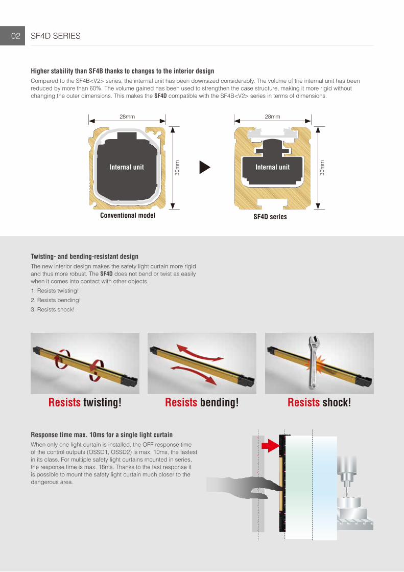
Higher stability than SF4B thanks to changes to the interior designCompared to the SF4B<V2> series, the internal unit has been downsized considerably. The volume of the internal unit has been reduced by more than 60%. The volume gained has been used to strengthen the case structure, making it more rigid without changing the outer dimensions. This makes the SF4D compatible with the SF4B<V2> series in terms of dimensions.
Twisting- and bending-resistant designThe new interior design makes the safety light curtain more rigid and thus more robust. The SF4D does not bend or twist as easily when it comes into contact with other objects.
1. Resists twisting!
2. Resists bending!
3. Resists shock!
Response time max. 10ms for a single light curtainWhen only one light curtain is installed, the OFF response time of the control outputs (OSSD1, OSSD2) is max. 10ms, the fastest in its class. For multiple safety light curtains mounted in series, the response time is max. 18ms. Thanks to the fast response it is possible to mount the safety light curtain much closer to the dangerous area.

SF4D SERIES 03
Easy calculation of safety distance thanks to special no-blind zone designThe SF4D inherits the no-blind zone design of the SF4B series. Even in an L-shaped or U-shaped layout, the beam pitch does not change (excluding finger protection type). This makes the calculation of the safety distance easier.
Impervious to liquids and dustThe safety light curtain has IP67 and IP65 (IEC) degree of protection and complies with NEMA Type 13 (NEMA: National Electrical Manufacturers Association), a standard to determine how well the enclosures of electronic components resist the infiltration of dust and moisture. For details refer to NEMA 250 “Enclosures for Electrical Equipment (1000 volts Maximum)”.
Easy installation of emitter and receiver thanks to improved optical propertiesThanks to a higher emission power, the SF4D not only works reliably on shorter distances, but also covers a longer sensing range than previous models.
Sensing range
Mode Type of protection Sensing range
Short mode (default setting)
Finger protection type 0 to 7m
Hand protection type Arm / Foot protection type 0 to 9m
Long mode
Finger protection type 0 to 12m
Hand protection type Arm / Foot protection type 0 to 15m
Please note that installing the front protection cover reduces the sensing range.
SF4D SERIES04
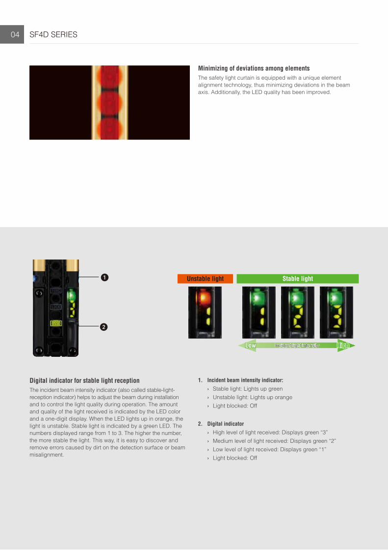
Unstable light Stable light
Incident light intensity HighLow
Digital indicator for stable light receptionThe incident beam intensity indicator (also called stable-light- reception indicator) helps to adjust the beam during installation and to control the light quality during operation. The amount and quality of the light received is indicated by the LED color and a one-digit display. When the LED lights up in orange, the light is unstable. Stable light is indicated by a green LED. The numbers displayed range from 1 to 3. The higher the number, the more stable the light. This way, it is easy to discover and remove errors caused by dirt on the detection surface or beam misalignment.
1. Incident beam intensity indicator: › Stable light: Lights up green › Unstable light: Lights up orange › Light blocked: Off
2. Digital indicator › High level of light received: Displays green “3” › Medium level of light received: Displays green “2” › Low level of light received: Displays green “1” › Light blocked: Off
Minimizing of deviations among elementsThe safety light curtain is equipped with a unique element alignment technology, thus minimizing deviations in the beam axis. Additionally, the LED quality has been improved.

SF4D SERIES 05
Optical synchronization
Synchronization by wiring
Synchronization by wiring
Selectable synchronization method and cable to suit various applications
Optical synchronization
With the SF4D, customers can select the synchronization method and cables according to their specific application and requirements. They can choose freely between a basic and a safety-enhanced configuration with improved operability.
Optical synchronization is suitable when emitter and receiver are installed far apart.
Synchronization by wiring (12-core cable) is suitable when the appli-cation indicators and the muting function are to be used.
Optical synchronization Synchronization by wiring
Cable type 5-core 12-core 8-core 12-core
Function
Interlock function Software ✔ (Software) ✔ (Software)
Lockout release function ✔ ✔ ✔ ✔
Test input function ✔ ✔ ✔ ✔
Auxiliary output (non-safety output) function ✔ (Software) ✔ (Software) ✔ (Software)
External device monitor function ✔ (Software) ✔ (Software) ✔ (Software)
Muting / Override function Software ✔ (Software)
Application indicator function Software ✔ (Software) Software ✔ (Software)
Parallel interference prevention function Software
Fix blanking function Software Software Software Software
Floating blanking function Software Software Software Software
✔: Function is activated by defaultSoftware: Function can be activated in the setting software✔ (Software): Function is activated by default and can be expanded in the setting software

SF4D SERIES06
Compliant with international standards
IEC 61496-1/2 (Type 4), ISO 13849-1 (Category 4, PLe), IEC 61508-1 to 7 (SIL3)
North AmericaANSI/UL 61496-1/2 (Type 4)CAN/CSA C22.2 No.14CAN/CSA E61496-1/2
JapanJIS B 9704-1/2 (Type 4)JIS B 9705-1 (Category 4)JIS C 0508-1 to 7 (SIL3)
EuropeEN 61496-1/2 (Type 4)EN ISO 13849-1 (Category 4, PLe)EN 55011EN 61000-6-2EN 50178
ChinaGB 4584
KoreaS1-G-1-2009S2-W-5-2009
Supports both PNP and NPN polaritiesEvery model in the SF4D series supports both PNP transistor output and NPN transistor output. Thus, the SF4D series prod-ucts are suitable for all types of control circuits used around the world. This feature allows our customers to use the prod-
uct in many different scenarios, for example when NPN sen-sors are replaced, when the positive pole is grounded in the factory, when equipment has to be moved to facilities in other countries, etc.
PNP circuitOutput polarity setting cable
PNP / NPN polarity indicator
NPN circuit
Easy change of polarity by wiringFor a PNP output, connect the output polarity setting wire to 0V. For an NPN output, connect the output polarity setting wire to +24V.
At the time of power ON, the indicator shows the selected
polarity (PNP or NPN).
The SF4D series’ complies with many international standards and thus can be used anywhere in the world.
International standards

SF4D SERIES 07
Safety light curtainSF4D series
Communication unit SF4D-TM1 (optional)
Setting software
Configurator Light Curtain
List of available functions
› Operation monitoring » Monitoring of the incident beam in-tensity and extraneous light
» I/O monitoring › Error history display › Light blockage history, unstable light
incidence history
› Muting setting function › Override setting function › Blanking setting function
(both fixed and floating blanking) › External device monitoring setting
function › Auxiliary output setting function
The handy controller software, which was well-received by users of our previous models, has evolved. The new setting software Configurator Light Curtain allows visually intuitive operation. Apart from providing powerful support during setup of the SF4D series, it helps to maintain stable operation and perform troubleshooting. The software saves the error history and allows real-time monitoring of the incident beam intensity.
Main functions
Which functions are available depends on the synchronization method and the type of cables (5-core, 8-core, 12-core) used.
Monitoring of received light intensity and extraneous light during operationThe monitoring function displays the incident beam intensity of the individual beams in real time. This makes setup much easier and streamlines the maintenance planning as you can see at a glance whether the beams have become misaligned or the light reception
has deteriorated, e.g. because the detection surface of the receiver is dirty. In addition, the function also monitors whether a beam of the safety light curtain is influenced by extraneous light to prevent mal-functions in advance.
PC
*2
*1
*1*1
*2 SF4D series only
PLC
The safety output is separated from IO-Link communication.
Safety Light CurtainSF4D series
IO-Link Communication Unit
SFD-WL3*1: 8-core cable for safety light curtain (optional)
*2: 4-core cable with M12 connector (commercially available, see note)
Safety PLC
Note: The master and the communication unit must be connected with a cable of min. Ø0.3mm2. The total length of the cable must not exceed 20m.
master unit
NEW

SF4D SERIES08
Muting mode Description
Parallel 4-sensorCross 2-sensor
With this mode, 2 muting sensors or 2 muting sensor pairs are installed sequentially or crosswise. You need to input the time it takes for the workpiece to pass through the protected area.
Exit-onlyWith this mode, a muting sensor needs to be installed only on the dangerous side. The safe side (exit side) does not need a muting sensor.
Simultaneous inputThis is used when the installation conditions do not allow the sensors to be installed sequentially and it is necessary to work with a simultaneous muting sensor input.
Muting functionThis function is used to set the arrangement of muting sen-sors and select the most suitable settings. The software dis-plays a time chart reflecting the actual input timing to facilitate adjustments.
Communication unit with copy functionWhen it is not possible to connect a PC to the safety light cur-tain, the communication unit can be used to write the setting data to the safety light curtain and also to read error information.
Check the settings
Using only the communication unit
WRITE
READ
Communication unit SF4D seriesUse the WRITE button on the communication unit to write settings.
Write data to another system.
Just take the communication unit with you.
SF4D series Communication unitUse the READ button to read settings or error information.
PCUSB2.0 cable (not included, connectors A and Mini-B)
Communication unit SF4D-TM1 (optional)
In the office At the installation site
Blanking functionThe blanking function has also become more advanced. It supports not only manual setting while allowing the user to check the light reception in real time, but also batch setting based on teaching.
Furthermore, fixed blanking and floating blanking can be set using the same screen, making configuration much easier and faster.

SF4D SERIES 09
Safety light curtain
Cable / protective tubeBottom cap cable
Discrete wire
Communication unit Y-shaped connector
Front protection cover Laser alignment toolCorner mirror Safety control units
Connector With connector on one end With connectors on both ends
Extension cable
Cable for series connection Protective tube
Options
Mounting bracket
Beam adjustment mounting bracket
Finger protection typeMin. object to be sensed ø14mm(10mm beam pitch)
Hand protection typeMin. object to be sensed ø25mm(20mm beam pitch)
Arm / Foot protection typeMin. object to be sensed ø45mm(40mm beam pitch)
Blind zone-less mounting Intermediate supporting bracket
List of options for safety light curtain
Sold separately

SF4D SERIES10
Finger protection type (min. object to be sensed ø14mm, 10mm beam pitch)Model No. Sensing range No. of beam channels Protective height Beam pitch
SF4D-F15
0 to 7m (short mode)0 to 12m (long mode)
(selectable by DIP switch)
15 150mm
10mm
SF4D-F23 23 230mm
SF4D-F31 31 310mm
SF4D-F39 39 390mm
SF4D-F47 47 470mm
SF4D-F55 55 550mm
SF4D-F63 63 630mm
SF4D-F71 71 710mm
SF4D-F79 79 790mm
SF4D-F95 95 950mm
SF4D-F111 111 1110mm
SF4D-F127 127 1270mm
Hand protection type (min. object to be sensed ø25mm, 20mm beam pitch)Model No. Sensing range No. of beam channels Protective height Beam pitch
SF4D-H8
0 to 9m (short mode)0 to 15m (long mode)
(selectable by DIP switch)
8 150mm
20mm
SF4D-H12 12 230mm
SF4D-H16 16 310mm
SF4D-H20 20 390mm
SF4D-H24 24 470mm
SF4D-H28 28 550mm
SF4D-H32 32 630mm
SF4D-H36 36 710mm
SF4D-H40 40 790mm
SF4D-H48 48 950mm
SF4D-H56 56 1110mm
SF4D-H64 64 1270mm
SF4D-H72 72 1430mm
SF4D-H80 80 1590mm
SF4D-H88 88 1750mm
SF4D-H96 96 1910mm

SF4D SERIES 11
Arm / Foot protection type (min. object to be sensed ø45mm, 40mm beam pitch)Model No. Sensing range No. of beam channels Protective height Beam pitch
SF4D-A4
0 to 9m (short mode)0 to 15m (long mode)
(selectable by DIP switch)
4 150mm
40mm
SF4D-A6 6 230mm
SF4D-A8 8 310mm
SF4D-A10 10 390mm
SF4D-A12 12 470mm
SF4D-A14 14 550mm
SF4D-A16 16 630mm
SF4D-A18 18 710mm
SF4D-A20 20 790mm
SF4D-A24 24 950mm
SF4D-A28 28 1110mm
SF4D-A32 32 1270mm
SF4D-A36 36 1430mm
SF4D-A40 40 1590mm
SF4D-A44 44 1750mm
SF4D-A48 48 1910mm
Mounting bracketsThe safety light curtain does not come with a mounting bracket. Please order it separately.
Mounting bracket type Model No. Required bolts Description
Beam adjustment mounting bracket
MS-SFD-1-5 2 M5 or 1 M8 hexagon-socket head bolt(s)
• For rear or side mounting
• 4 pieces/set for emitter and receiver
• Material: cold-rolled carbon steel (SPCC)
MS-SFD-1-6 1 M6 hexagon-socket head bolt
MS-SFD-1-8 1 M8 hexagon-socket head bolt
Beam adjustment mounting bracket for installation without blind zones (notes 1 and 2) MS-SFD-3-6 2 M5 or 2 M6
hexagon-socket head bolts
• For rear or side mounting
• 4 pieces/set for emitter and receiver
• Material: die-cast zinc alloy
Intermediate supporting bracket (note 3) MS-SFB-2 2 M5 hexagon-socket head bolts
• Supports the middle of the safety light curtain in locations subject to vibration.
• 2 pieces/set for emitter and receiver
• Material: die-cast zinc alloy
Notes:1.) The required number for emitter and receiver varies depending on the number of beam channels.2.) The mounting brackets must extend beyond the protective height for ensure there is no blind zone.3.) One set is required when the number of beam channels is more than 111 beam channels for SF4D-F□, more than 56 beam channels for SF4D-H□, and more than 28 beam channels for
SF4D-A□.

SF4D SERIES12
Extension cables: with connector on one endType Model No. Length Weight Description
5-coreSFD-CC3-S 3m 260g approx. (2 cables)
• Used for connecting the safety light curtain to an extension cable or the safety control unit SF-C13 / SF-C21
• 2 pieces/set for emitter and receiver
• Connector outer diameter: max. ø14mm
SFD-CC10-S 10m 830g approx. (2 cables)
8-coreSFD-CC3 3m 290g approx. (2 cables)
SFD-CC10 10m 620g approx. (2 cables)
12-core
SFD-CC3-MU 3m 340g approx. (2 cables) • Used for connecting the safety light curtain to an extension cable or the safety control unit SF-C13 / SF-C21
• 2 pieces/set for emitter and receiver
• Connector outer diameter: max. ø16mm
SFD-CC7-MU 7m 700g approx. (2 cables)
SFD-CC10-MU 10m 980g approx. (2 cables)
CablesThe safety light curtain does not come with bottom cap, extension or adapter cables. Please order them separately.
Bottom cap cable
All bottom cap cables are available as 5-core, 8-core, 12-core cables with 2 pieces per set. On the emitter side, the connector is gray. On the receiver side, the connector is black.
Discrete wire type
Connector type
Cable type Model No. Length Weight Description
5-core
Discrete wireSFD-CCB5-S 5m 420g approx. (2 cables) • Used for connecting the safety light curtain to other cables or the
safety control unit SF-C13 / SF-C21
• 2 pieces/set for emitter and receiverSFD-CCB10-S 10m 830g approx. (2 cables)
Connector SFD-CB05-S 0.5m 75g approx. (2 cables)
• Used for connecting the safety light curtain to an extension cable
• 2 pieces/set for emitter and receiver
• Connector outer diameter: max. ø14mm
8-core
Discrete wire
SFD-CCB3 3m 290g approx. (2 cables)
• Used for connecting the safety light curtain to other cables or the safety control unit SF-C13 / SF-C21
• 2 pieces/set for emitter and receiver
SFD-CCB7 7m 620g approx. (2 cables)
SFD-CCB10 10m 900g approx. (2 cables)
SFD-CCB15 15m 1300g approx. (2 cables)
Connector
SFD-CB05 0.5m 80g approx. (2 cables) • Used for connecting the safety light curtain to an extension cable or the safety control unit SF-C11
• 2 pieces/set for emitter and receiver
• Connector outer diameter: max. ø14mm
SFD-CB5 5m 480g approx. (2 cables)
SFD-CB10 10m 950g approx. (2 cables)
12-core
Discrete wire
SFD-CCB3-MU 3m 340g approx. (2 cables) • Used for connecting the safety light curtain to other cables or the safety control unit SF-C13 / SF-C21
• 2 pieces/set for emitter and receiverSFD-CCB7-MU 7m 700g approx. (2 cables)
SFD-CCB10-MU 10m 980g approx. (2 cables)
Connector SFD-CB05-MU 0.5m 95g approx. (2 cables)
• Used for connecting the safety light curtain to an extension cable
• 2 pieces/set for emitter and receiver
• Connector outer diameter: max. ø16mm
Extension cablesAll extension cables are available as 5-core, 8-core, 12-core cables. Note that the number of wires in an extension cable must match the number of wires in the bottom cap cable to be extended.

SF4D SERIES 13
Extension cables: with connectors on both endsType Model No. Length Weight Description
5-core
For emitter (gray connector) SFD-CCJ10E-S 10m 420g approx. (1 cable) • Used for connecting the safety light curtain to an
extension cable
• 1 cable for emitter, 1 cable for receiver
• Connector outer diameter: max. ø14mmFor receiver (black connector) SFD-CCJ10D-S 10m 440g approx. (1 cable)
8-core
For emitter (gray connector)
SFB-CCJ3E 3m 190g approx. (1 cable)
• Used for connecting the safety light curtain to an extension cable or the safety control unit SF-C11
• 1 cable for emitter, 1 cable for receiver
• Connector outer diameter: max. ø14mm
SFB-CCJ10E 10m 580g approx. (1 cable)
For receiver (black connector)
SFB-CCJ3D 3m 210g approx. (1 cable)
SFB-CCJ10D 10m 600g approx. (1 cable)
12-core
For emitter (gray connector)
SFB-CCJ3E-MU 3m 190g approx. (1 cable)
• Used for connecting the safety light curtain to an extension cable
• 1 cable for emitter, 1 cable for receiver
• Connector outer diameter: max. ø14mm
SFB-CCJ10E-MU 10m 660g approx. (1 cable)
For receiver (black connector)
SFB-CCJ3D-MU 3m 210g approx. (1 cable)
SFB-CCJ10D-MU 10m 680g approx. (1 cable)
Cable for series connectionModel No. Length Net weight Description
SFD-CSL005 0.05m 35g approx. (2 cables)
• Used for connecting the safety light curtain in series. If this device is to be installed in an L-shaped layout, we recommend using a cable with a minimum length of 0.1m.
• 2 pieces/set for emitter and receiver (common for emitter and receiver)
• Cable color: gray with black line (common for emitter and receiver)
• The minimum bending radius is 6mm. However, when the protective tube SFPD-A10 is attached, the minimum bending radius of the cable is 55mm.
SFD-CSL01 0.1m 40g approx. (2 cables)
SFD-CSL05 0.5m 80g approx. (2 cables)
SFD-CSL1 1m 130g approx. (2 cable)
SFD-CSL5 5m 480g approx. (2 cables)
SFD-CSL10 10m 950g approx. (2 cables)
Adapter cableType Model No. Length Net weight Description
For SF4-AH□ (PNP type) SFD-CB05-A-P
0.5m 80g approx. (2 cables)
• Used to allow connector cables attached to older series of safety light curtains at the control circuit side to be connected to the SF4D series
• 2 pieces/set for emitter and receiver
• Connector outer diameter: max. ø14mm
• The minimum bending radius is 6mm. However, when the protective tube SFPD-A10 is attached, the minimum bending radius of the cable is 55mm.For SF4-AH□-N (NPN type) SFD-CB05-A-N
Note: Where the cable color has not been specified, it is black for emitter, gray with black line for the receiver.
Protective tubeModel No. Length Net weight Description
SFPD-A10 10m 220g approx. (1 cable)
• Outer diameter: ø18mm, inner diameter: ø9mm
• Minimum bending radius: 55mm
• Material: Polycarbonate

SF4D SERIES14
Safety control units
Type of safety control unit Model No. Compatible cables
Standard type SF-C21 • Bottom cap cable: SFD-CCB□ Extension cable: SFD-CC□
Connector type SF-C11 • Bottom cap cable: SFD-CB□ Extension cable: SFB-CCJ□
Slim type SF-C13 • Bottom cap cable: SFD-CCB□ Extension cable: SFD-CC□
Recommended safety relaysThe recommended relays are equipped with an LED indicator.
Model No. SFS3-L-DC24V SFS4-L-DC24V
Contact arrangement 3a1b 4a2b
Rated switching capacity 6A/250V AC, 6A/30V DC
Min. switching capacity 1mA/5V DC
Coil power 15mA/24V DC 20.8mA/24V DC
Rated power consumption 360mW 500mW
Operation time Max. 20ms
Release time Max. 20ms
Ambient temperature -40 to +85°C (humidity: 5 to 85% RH)
Applicable standards UL, C-UL, TUV, Korea’s S-mark
Communication unit
The communication unit acts as an interface between a PC and a safety light curtain of the SF4D series. It has two functions: You can use it to change settings and monitor the status of SF4D safety light curtains with a PC or you can copy settings from one safety light curtain to another without a PC. The communication unit connects to the PC with a USB cable (USB2.0, connectors A and Mini-B, not included) and to the safety light curtains with the cable attached.
If you want to use the SF4D-TM1 communication unit with a PC, you need to install the setting software “Configurator Light Curtain”, which can be down-loaded for free from our website.
Model No. SFS SET
Description Safety relays set (two relays SFS4-L-DC24V-D and two sockets SFS6SFDJ) for light curtains
IO-Link communication unitType Model No. Description
IO-Link communication unit for the SF4D series SFD-WL3 Used to transmit various types of safety light curtain data via
IO-Link communication
SF4D SERIES 15
Common specifications
TypeFinger protection type Hand protection type Arm / Foot protection type
Min. object to be sensed ø14mm (10mm beam pitch)
Min. object to be sensed ø25mm (20mm beam pitch)
Min. object to be sensed ø45mm (40mm beam pitch)
Model No. SF4D-F□ SF4D-H□ SF4D-A□
Applicable standards
International standards IEC 61496-1/2 (Type 4), ISO 13849-1 (Category 4, PLe), IEC 61508-1 to 7 (SIL3)
Japan JIS B 9704-1/2 (Type 4), JIS B 9705-1 (Category 4), JIS C 0508-1 to 7 (SIL3)
Europe (EU) EN 61496-1/2 (Type 4), EN ISO 13849-1 (Category 4, PLe), EN 55011, EN 61000-6-2, EN 50178
North America ANSI/UL 61496-1/2 (Type 4), CAN/CSA C22.2 No.14, CAN/CSA E61496-1/2
South Korea (S-Mark) S1-G-1-2009, S2-W-5-2009
China (GB) GB 4584
Applicable CE marking directive Machinery Directive, EMC Directive, RoHS Directive
Sensing range0 to 7m (short mode)0 to 12m (long mode)(selectable by DIP switch)
0 to 9m (short mode)0 to 15m (long mode)(selectable by DIP switch)
Min. object to be sensed (note 2) ø14mm opaque object ø25mm opaque object ø45mm opaque object
Effective aperture angle Max. ±2.5° at a sensing range of min. 3m (based on IEC 61496-2)
Supply voltage 24V DC +20/-30% including ripple max. 10% (P-P) (excluding voltage drop when cable is removed)
Control outputs (OSSD 1, OSSD 2)
PNP open-collector transistor / NPN open collector transistor (selectable) PNP output selected:Maximum source current: 350mAApplied voltage: Same as supply voltage (between control output and +V)Residual voltage: max. 2V (source current 350mA) (excluding voltage drop due to cable)Leakage current: max. 0.2mA (including power OFF state)Maximum load capacity: 2.2μFLoad wiring resistance: max. 3Ω
NPN output selected:Maximum sink current: 350mAApplied voltage: Same as supply voltage (between control output and 0V)Residual voltage: max. 2V (sink current 350mA) (excluding voltage drop due to cable)Leakage current: max. 0.2mA (including power OFF state)Maximum load capacity: 2.2μFLoad wiring resistance: max. 3Ω
Operation mode ON when all beams are received, OFF when one or more beams are blocked (also OFF when an internal sensor error or synchronization signal error occurs)
Protection circuit Incorporated
Response time OFF response: max. 10ms (when not connected in series / parallel), max. 18ms (when connected in series / parallel) ON response: max. 50ms (note 3 and 4)
Auxiliary output (AUX) (non-safety output) PNP open-collector transistor / NPN open collector transistor (selectable)
Synchronization method Synchronization by wiring / optical synchronization (selectable by DIP switch)
Interference prevention function
Not connected in series / parallel:Synchronization by wiring: max. 2 units (auto)Optical synchronization: max. 2 units (selectable by DIP switch)
Connected in series / parallel:Series connection: max. 5 units (total number of beam channels max. 256)Parallel connection: max. 3 units (total number of beam channels max. 192)Series / parallel connection mixed: max. 5 units (total number of beam channels max. 144)
Test input function Incorporated
Interlock function IncorporatedManual reset / auto reset: selectable by wiring
Use 8-core cable or 12-core cable
Lockout release function Incorporated
External device monitor function Incorporated (use 8-core cable or 12-core cable)
Muting function Incorporated (use 12-core cable)
Override function Incorporated (use 12-core cable)
Degree of protection IP67, IP65 (IEC), NEMA Type 13 (NEMA 250)
Ambient temperature -10 to +55°C (No dew condensation or icing allowed), storage: -25 to 60°C
Accessories SF4B-TR14 (Test rod): 1 pc. SF4B-TR25 (Test rod): 1 pc. -
Notes:1.) Where measurement conditions have not been specified precisely, the conditions used were an ambient temperature of +20°C.2.) When the floating blanking function is used, the minimum size of the object to be sensed becomes larger.3.) Because the control output (OSSD 1 / 2) must be OFF for at least 80ms, the ON response will be delayed more than 50ms when the light blocked time is less than 30ms.4.) When optical synchronization is selected, if the beam axes of both the top end and bottom end are blocked, the ON response speed decreases by as much as 1 second.

Panasonic Electric WorksPlease contact our Global Sales Companies in:
Europe
▸ Headquarters Panasonic Electric Works Europe AG Robert-Koch-Straße 100, 85521 Ottobrunn, Tel. +49 89 45354-1000, Fax +49 89 45354-2111, www.panasonic-electric-works.com▸ Austria Panasonic Electric Works Austria GmbH Josef Madersperger Str. 2, 2362 Biedermannsdorf, Tel. +43 (0) 2236-26846, Fax +43 (0) 2236-46133
www.panasonic-electric-works.atPanasonic Industrial Devices Materials Europe GmbH
Ennshafenstraße 30, 4470 Enns, Tel. +43 (0) 7223 883, Fax +43 (0) 7223 88333, www.panasonic-electronic-materials.com
▸ Benelux Panasonic Electric Works Sales Western Europe B.V.
De Rijn 4, (Postbus 211), 5684 PJ Best, (5680 AE Best), Netherlands, Tel. +31 (0) 499 372727, Fax +31 (0) 499 372185, www.panasonic-electric-works.nl
▸ Czech Republic Panasonic Electric Works Europe AG, organizační složka
Administrative centre PLATINIUM, Veveří 3163/111, 616 00 Brno, Tel. +420 541 217 001, Fax +420 541 217 101, www.panasonic-electric-works.cz
▸ France Panasonic Electric Works Sales Western Europe B.V.
Succursale française, 10, rue des petits ruisseaux, 91370 Verrières Le Buisson, Tél. +33 (0) 1 6013 5757, Fax +33 (0) 1 6013 5758, www.panasonic-electric-works.fr
▸ Germany Panasonic Electric Works Europe AG Robert-Koch-Straße 100, 85521 Ottobrunn, Tel. +49 89 45354-1000, Fax +49 89 45354-2111, www.panasonic-electric-works.de▸ Hungary Panasonic Electric Works Europe AG Magyarországi Közvetlen Kereskedelmi Képviselet, 1117 Budapest, Neumann János u. 1., Tel. +43 2236 26846-25,
Mobile: +36 20 264 9896, Fax +43 2236 46133, www.panasonic-electric-works.hu▸ Ireland Panasonic Electric Works UK Ltd. Irish Branch Offi ce, Dublin, Tel. +353 (0) 14600969, Fax +353 (0) 14601131, www.panasonic-electric-works.co.uk▸ Italy Panasonic Electric Works Italia srl Via del Commercio 3-5 (Z.I. Ferlina), 37012 Bussolengo (VR), Tel. +39 0456752711, Fax +39 0456700444,
www.panasonic-electric-works.it▸ Nordic Countries Panasonic Electric Works Europe AG
Panasonic Eco Solutions Nordic ABFilial Nordic, Knarrarnäsgatan 15, 164 40 Kista, Sweden, Tel. +46 859476680, Fax +46 859476690, www.panasonic-electric-works.seJungmansgatan 12, 21119 Malmö, Tel. +46 40 697 7000, Fax +46 40 697 7099, www.panasonic-fi re-security.com
▸ Poland Panasonic Electric Works Polska sp. z o.o ul. Wołoska 9A, 02-583 Warszawa, Tel. +48 42 230 9633, www.panasonic-electric-works.pl▸ Spain Panasonic Electric Works España S.A. Barajas Park, San Severo 20, 28042 Madrid, Tel. +34 913293875, Fax +34 913292976, www.panasonic-electric-works.es▸ Switzerland Panasonic Electric Works Schweiz AG Grundstrasse 8, 6343 Rotkreuz, Tel. +41 (0) 41 7997050, Fax +41 (0) 41 7997055, www.panasonic-electric-works.ch▸ United Kingdom Panasonic Electric Works UK Ltd. Sunrise Parkway, Linford Wood, Milton Keynes, MK14 6 LF, Tel. +44 (0) 1908 231555, Fax +44 (0) 1908 231599,
www.panasonic-electric-works.co.uk
North & South America
▸ USA Panasonic Industrial Devices Sales Company of America
Two Riverfront Plaza, 7th Floor, Newark, NJ 07102-5490, Tel. 1-8003-442-112, www.pewa.panasonic.com
Asia Pacifi c / China / Japan
▸ China Panasonic Electric Works Sales (China) Co. Ltd. Tower C 3rd Floor, Offi ce Park, NO.5 Jinghua South Street, Chaoyang District, Beijing 100020, Tel. +86-10-5925-5988, Fax +86-10-5925-5980
▸ Hong Kong Panasonic Industrial Devices Sales (HK) Co., Ltd.
Suite 301, 3/F, Chinachem Golden Plaza, 77 Mody Road, TST East, Kowloon, Hong Kong, Tel. +852-2529-3956, Fax +852-2528-6991
▸ Japan Panasonic Corporation 1006, Oaza Kadoma, Kadoma-shi, Osaka 571-8501, Japan, Tel. +81-6-6908-1121, www.panasonic.net▸ Singapore Panasonic Industrial Devices
Automation Controls Sales Asia Pacifi cNo.3 Bedok South Road, Singapore 469269, Tel. +65-6299-9181, Fax +65-6390-3953
Global Network
Asia Pacific China JapanNorth America Europe
Global Network
Copyright © 2018 • Printed in Germany 3234euen 10/18


![TME-DC [ ] - Sew Many Parts, Inc. of Contents z TME-DC GENERAL VIEW z TME-DC FRAME … CD-1 z TME-DC TABLE … CD-2-1 z TME-DC AUTO SUB TABLE …](https://static.fdocuments.net/doc/165x107/5b1d28797f8b9add7f8b64eb/tme-dc-sew-many-parts-inc-of-contents-z-tme-dc-general-view-z-tme-dc-frame.jpg)
