Safety Investigation Report - mobilit.belgium.be · This aeroplane bears the serial number 01,...
28
Final report SYNOPSYS 1/28 Air Accident Investigation Unit (Belgium) City Atrium Rue du Progrès 56 1210 Brussels Safety Investigation Report Ref. AAIU-2016-AII-08 Issue date: 14 November 2018 Status: Final SYNOPSIS Classification: Accident Level of investigation: Standard Date and time: 08 October 2016 at 14:36 UTC Aircraft: Fournier RF 47, MSN: 01 Owner: Private Accident location: In a field in Oordegem (Belgium), Geographic coordinates: 50°57’58,29 – 3°53’46,59 Type of operation: Non-commerical - Cross-Country Phase: En route Persons on board: One pilot Injuries: The pilot was slightly injured Abstract During a navigation flight, the engine began to sputter and lose power. The pilot searched for a suitable location for a forced landing and decided to land on a ploughed field. The engine completely stopped operating in final before touch-down. During the landing, the aeroplane flipped over, leaving the pilot slightly injured and the aeroplane significantly damaged. Cause The direct cause of the accident (the flip-over) is an improper pitch-up attitude (not enough “holding off”) during a forced landing on a soft terrain as a consequence of an engine failure. The engine breakdown (=indirect cause) was due to an insufficient gap between the valve rotators and the rocker arms. This caused an unwanted mechanical contact between these parts followed by a rapid wear of the valve keys ending in the engine failure. Contributing safety factor: Performing non-routine maintenance on critical aircraft components without having extensive technical experience. Other safety factor: The lack of technical documentation and/or guidance from the engine manufacturer to warn the mechanics about the “valve stem wear phenomenon”, possibly causing an insufficient gap between the valve rotators and the rocker arms.
Transcript of Safety Investigation Report - mobilit.belgium.be · This aeroplane bears the serial number 01,...

Fin
al re
po
rt S
YN
OP
SY
S
1/28
Air Accident Investigation Unit (Belgium)
City Atrium Rue du Progrès 56
1210 Brussels
Safety Investigation Report Ref. AAIU-2016-AII-08
Issue date: 14 November 2018 Status: Final
SYNOPSIS Classification: Accident Level of investigation: Standard Date and time: 08 October 2016 at 14:36 UTC Aircraft: Fournier RF 47, MSN: 01 Owner: Private Accident location: In a field in Oordegem (Belgium), Geographic coordinates: 50°57’58,29 – 3°53’46,59 Type of operation: Non-commerical - Cross-Country Phase: En route Persons on board: One pilot Injuries: The pilot was slightly injured Abstract During a navigation flight, the engine began to sputter and lose power. The pilot searched for a suitable location for a forced landing and decided to land on a ploughed field. The engine completely stopped operating in final before touch-down. During the landing, the aeroplane flipped over, leaving the pilot slightly injured and the aeroplane significantly damaged. Cause The direct cause of the accident (the flip-over) is an improper pitch-up attitude (not enough “holding off”) during a forced landing on a soft terrain as a consequence of an engine failure. The engine breakdown (=indirect cause) was due to an insufficient gap between the valve rotators and the rocker arms. This caused an unwanted mechanical contact between these parts followed by a rapid wear of the valve keys ending in the engine failure.
Contributing safety factor:
Performing non-routine maintenance on critical aircraft components without having extensive technical experience. Other safety factor: The lack of technical documentation and/or guidance from the engine manufacturer to warn the mechanics about the “valve stem wear phenomenon”, possibly causing an insufficient gap between the valve rotators and the rocker arms.

AAIU-2016-AII-08
Fin
al re
po
rt F
AC
TU
AL
IN
FO
RM
AT
ION
2/28
FACTUAL INFORMATION
1.1 History of the flight
Shortly before the accident, the engine had been repaired due to a loss of compression. After carrying out the engine repair involving the replacement of the exhaust valves, the owner performed a ground run of the engine and made subsequently a satisfactory local flight in the vicinity of the home base of Grimbergen (EBGB). In the morning of Sunday 8 October, the pilot performed a first cross-country flight to the aerodrome of Koksijde (EBFN) without any degradation in performance. However, during the return flight in the afternoon, the engine began to sputter and lose power. At the same time, the pilot noticed an unusual oil smell. The pilot searched for a suitable location for a forced landing, lowered the flaps and decided to land on a ploughed field. The engine stopped operating in short final above a row of trees located at the beginning of the chosen field. The aeroplane touched down approximately at mid-length of the field at 380 meters from the row of threes and rolled between 10 – 15 m before it became airborne again for about 10 meters. Thereafter, the aeroplane touched down again causing the nose wheel to sink into the soft ground causing a rapid deceleration. The nose landing gear strut failed rearwards and the aeroplane flipped over. The pilot, slightly injured, managed to leave the cabin through the little space between the ground and the airframe structure after having somewhat dug the ground next to the wreckage.
Figure 1: Aerial view of the landing field
Direction of landing
Final rest position
AAIU-2016-AII-08
Fin
al re
po
rt F
AC
TU
AL
IN
FO
RM
AT
ION
3/28
Figure 2: Rest position of the wreckage
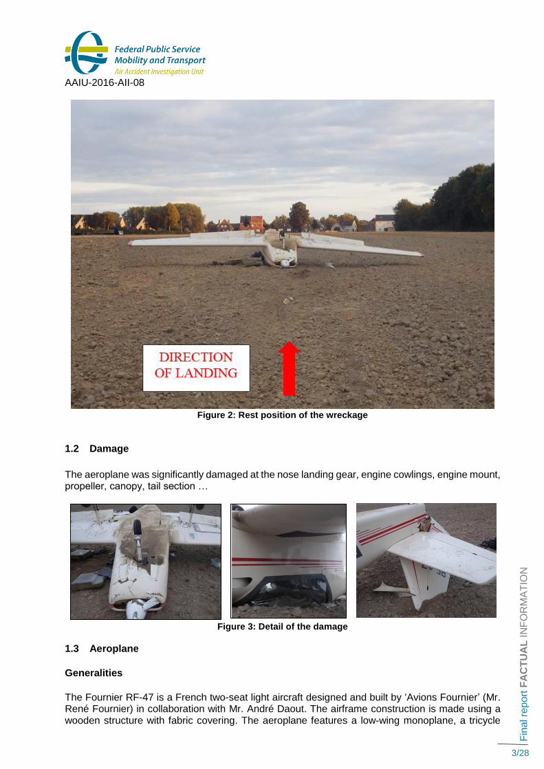
1.2 Damage
The aeroplane was significantly damaged at the nose landing gear, engine cowlings, engine mount, propeller, canopy, tail section …
Figure 3: Detail of the damage
1.3 Aeroplane
Generalities
The Fournier RF-47 is a French two-seat light aircraft designed and built by ‘Avions Fournier’ (Mr. René Fournier) in collaboration with Mr. André Daout. The airframe construction is made using a wooden structure with fabric covering. The aeroplane features a low-wing monoplane, a tricycle

AAIU-2016-AII-08
Fin
al re
po
rt F
AC
TU
AL
IN
FO
RM
AT
ION
4/28
landing gear and a fuselage-mounted horizontal stabilizer. The RF-47 has an enclosed cockpit with side-by-side configuration seating for two under a single-piece canopy that hinges at the rear. The Fournier RF-47 was type-certificated in France on 4 October 1995 and holds the Type Certificate data Sheet Nr 187 edition 1 (10.95). The RF-47 is classified in the EASA product list for Small Aeroplanes as “VLA Powered Sailplanes”. However, only 5 pre-series RF-47 were manufactured before the manufacturer stopped production. The prototype first flew on 9 April 1993 with a 90 hp (67 kW) Sauer engine. The certified version of the RF-47 was equipped with a Limbach L 2400 EB1 AA engine. Characteristics
• Crew: 2
• Length: 6.25 m
• Wingspan: 10.00 m
• Height: 2.10 m
• Wing area: 10.60 m² Performance
• Maximum speed: 270 km/h
• Cruising speed: 190 km/h
• Stall speed: 72 km/h
• Service ceiling: 4000 m
• G limits: +4.4 / -2.2
The accident aeroplane
• Manufacturer: Fournier René and Daout André • Model: RF-47 • SN: 01 • Year of manufacture: 1993 • Category: Non-EASA home-built aircraft (Also known as "Annex II" aircraft) • Total time A/C: 1246h6/10 flight hours (1243h9/10 at engine repair) • Registration: Registered in France (Restricted Registration Certificate) in the
name of the current owner since 18 July 2006. • Airworthiness certificate: Restricted Airworthiness Certificate1 delivered on 17 September
1996. • CNRA Validity: Renewed on 13 February 2016 – Valid until 13 February 2019 • Registration Certificate: Delivered by DGAC to the current owner on 18 July 2006. • Empty weight: 472,5 kg • Max take-off weight: 680 kg
This aeroplane bears the serial number 01, indicating it is the first RF-47 manufactured. Reportedly, this aeroplane would be the prototype of the RF-47. Upon its registration, DGAC France determined that the airplane did not comply with the “Fiche de Navigabilité N°187”, due to among others the installation of a different engine. DGAC therefore saw this airplane as a homebuilt construction and it was registered with this status as an “Annex II” aircraft. Permission to Fly over Belgian territory was not granted because this was never requested by the owner.
1 This Restricted Airworthiness Certificate (“CNRA” = Certificat de Navigabilité Restreint d’Aéronef) is valid only when associated with the “Dossier C.N.R.A. Nr 4169”.

AAIU-2016-AII-08
Fin
al re
po
rt F
AC
TU
AL
IN
FO
RM
AT
ION
5/28
Engine identification
• Manufacturer: Sauer • Model: ST-2500-H2S • SN: X1021 • Engine total time: About 1030 flight hours • Certification document: JAR-22(H) Geräte-Kennblatt Nr 4580 Ausgabe 4 dated
18 September 2003. The engine was type-certificated by the LBA (the German aviation authority) in 1995 (see “Geräte-Kennblatt Nr 4580 Ausgabe 4 dated 18.09.2003”).
Main engine cylinder, cylinder heads and valve problems history
17 October 2002 Installation of 4 new cylinders, 2 new cylinder heads, new push rods and new rocker valves. Engine TT: +/- 140 H. Repair performed by Avialaval (France) when the aeroplane was still owned by the previous owner.
10 January 2007 Leak test 1:74/80, 2: 70/80, 3: 79/80, 4: 50/80. Both cylinder heads were removed and replaced by new original parts delivered by the engine manufacturer (Sauer Engine). Engine TT: +/- 353 H. Repair performed by the owner.
22 July 2008 Cylinder Nr 4, piston and rings removed and replaced. Engine TT: +/-450 flight hours due to broken rings + scratches in the cylinder wall. Repair performed by the owner using parts purchased from the engine manufacturer.
September 2016 The engine showed some cylinder low compression. The pilot, assisted by a friend, removed both cylinder heads and found that one exhaust valve was burnt. Four new exhaust valves were purchased from the engine manufacturer and installed. No log book entry found. Engine TT: +/-1025 flight hours.
Maintenance documentation used by the pilot-owner The engine valve train system of the S 2500 is quite uncommon. Usually, valve trains are either manually adjusted (during periodical maintenance) or feature a hydraulic compensation for the valve lash (hydraulic tappets), where adjustment is automatic. The S 2500 engine valve train used a hybrid system incorporating at the same time a hydraulic compensation and a mechanical adjustment system where a mechanical pre-adjustment needs to be performed only in specific circumstances (Valve replacement …). The owner used, for the maintenance of the engine, an operator manual dated 01 November 1995, written in French and entitled ‘MANUEL D’UTILISATION pour Moteur Sauer ST2500H1S’. The owner stated that, during the last engine repair, the mechanical pre-adjustment of the valves was performed according to a handwritten addendum found in the operator manual ‘Chapter 7. Maintenance’.
7.4b Réglage soupape.
• Tourner la vis de réglage de sorte qu’un jeu nul soit atteint
• Ajouter 2 tours et serrer le contre-écrou
7.4b Valve adjustment (Translation)
• Turn the adjustment screw in order to obtain zero play
• Add 2 turns and tighten the locknut

AAIU-2016-AII-08
Fin
al re
po
rt F
AC
TU
AL
IN
FO
RM
AT
ION
6/28
Official technical documentation As stated in the type certification document “Geräte-Kennblatt Nr 4580 Ausgabe 4 dated 18.09.2003”, the technical documentation available for the maintenance of the engine is: • Maintenance manual and Parts catalog (written in German language): Reparaturbuch und
Ersatzteilkatalog für Motor S 2500, Ausgabe 01.03.2003 • Operator Manual (written in German language): Betriebshandbuch für Motor S 2500, Ausgabe
01.03.2003. The maintenance manual details the procedure to be followed to set the valves of an engine equipped with hydraulic compensation (hydraulic tappets) of the valve lash (clearance/play). However, reference is made to a “distribution housing” and “distributor rotor” that are not installed on this engine. “Distribution housing” and “distributor rotor” are typical parts of a car ignition system, suggesting that the text is copied from a car maintenance manual without the necessary changes.
Translation: Adjustment of the valve lash when equipped with
hydraulic valve lifters
• Turn back the setting screws of the rocker arms until
they are flush with the rocker arms.
• Set the crankshaft to the TDC of cylinder 1
(the distributor rotor must point to Nr 1 cylinder
marking at distributor housing)
• Turn the setting screws of both rocker arms until
they are slightly in contact with the valves (Without
clearance at the valve train).
• From this point, turn the setting screws one to two
turns further and lock them.
To proceed on cylinders 2, 3 and 4, turn the crankshaft further to the left until the distributor rotor is each time at an angle of 90°.
Figure 4: Extract of the maintenance manual
1.4 Engine inspection
An external inspection of the engine showed that two ignition cables were damaged by an abnormal contact with an exhaust pipe, likely due to a wrong cable routing. Traces of engine oil were present inside the exhaust pipe common to cylinder Nr 2 and Nr 4 (Exhaust of the cylinders located at the right side).
Figure 5: Cylinder sequence numbering
Figure 6: chafing of a high-tension ignition cable
on an exhaust pipe.

AAIU-2016-AII-08
Fin
al re
po
rt F
AC
TU
AL
IN
FO
RM
AT
ION
7/28
During the removal of the upper spark plugs, the cylinder Nr 2 spark plug was very hard to unscrew and showed extensive hammering damage after removal.
After removal of the Nr 2 and Nr 4 common cylinder head cover, the inspection of the valve trains showed that the intake valve of cylinder Nr 2 was missing (no longer present inside its guide) and the push rod of the cylinder 4 intake valve was no longer in place against its rocker arm. A worn valve key was found lying under the rocker arm as well as several small damaged pieces of metal. After disassembly of the rocker arm shaft, all rocker arms could be thoroughly examined. Close examination of the rocker arm of the failed valve (Nr 2 intake) showed an abnormal chafing of the rocker arm. This rocker arm was locally damaged by an abnormal contact with its rotator2 (generally known as its trademark Rotocap). Extreme damage to both combustion chambers and pistons was found after removal of Nr 2 and Nr 4 cylinders. The remains of the Nr 2 intake valve were found pressed into the aluminium casing of the combustion chamber.
Figure 5: Cylinders and pistons Nr 2 and Nr 4
The inspection after removal of the Nr 1 and Nr 3 cylinder head cover (left-side cylinders) also
showed evidence of an abnormal contact between the rotators and the intake valve rocker arms.
Figure 6: Cylinder Nr 3 lack of gap at intake valve train.
2 A rotator turns the valve slightly every time it opens or closes, preventing the valve sticking or burning

AAIU-2016-AII-08
Fin
al re
po
rt F
AC
TU
AL
IN
FO
RM
AT
ION
8/28
Figure 7: Contact areas between the rocker arm and the rotator
1.5 Pilot information
Sex: Male Age: 69 years old Nationality: Belgian License: EASA PART-FCL PPL (land) license. First delivered on 03
October 1984. Ratings: Class rating: SEP (land) valid until 31 May 2017 (training flight with
the accident aeroplane completed on 9 May 2015). Language Proficiency: English level 4 expired since 25 February 2016 Medical certificate: Valid until 19 December 2016 Flight experience: Total flight hours: 1546:26FH Last 6 months flight experience with the accident aeroplane:
Date Duration of the flight Take-offs and landings
Remark
16 April 2016 1:42 3
30 April 2016 2:06 2
06 May 2016 3:24 2
08 May 2016 3:42 2
30 May 2016 2:12 3
Begin October 2016 (Local test flight)
2:42 1 Date and duration of test flight unknown. Total hours of test flight + flights on 08 October 2016 = 2:42FH
08 October 2016 (Accident flight)
2
Total 15:48 15 (Including the crash landing)
The pilot owner held a fitness certificate for the maintenance of his own aircraft delivered by DGAC on 5 November 2012.

AAIU-2016-AII-08
Fin
al re
po
rt F
AC
TU
AL
IN
FO
RM
AT
ION
9/28
1.6 Meteorological information
Based on METARs from EBBR and EBAW, the meteorological conditions at the crash site were approximately as follows: Wind direction: 50° (variable from 10° to 90°), Windspeed: 8 kt, Prevailing visibility: more than 10 km, Ceiling: Scattered clouds at 4600 ft, QNH: 1024 hPa

AAIU-2016-AII-08
Fin
al re
po
rt A
NA
LY
SIS
10/28
ANALYSIS
2.1 The forced landing
The pilot stated that, several years before, he already experienced an engine failure when in command of another aeroplane. In this case, he performed a successful forced landing without any damage. Since this event, when in flight, aware that an engine failure can occur at any time, he scans the surroundings regularly for available fields to perform a forced landing. The pilot performed a satisfactory training flight with an instructor 7 months before the accident and had a large experience flying single engine aeroplane. All of this indicates that he was adequately prepared to perform a satisfactory forced landing, if necessary. The prevailing wind (50° - 8 kt) and the field orientation (143°) determined that the aeroplane probably landed in left crosswind conditions. However, based on the interview of the pilot, this does not seem to have caused particular difficulties. The traces left on the ground by the landing gear show that the aeroplane touched down on its 3 wheels, rolled for 10 metres, went airborne before touching down again in a flat attitude, on its 3 wheels. The owner stated that the cause of the flip over was an insufficient pitch-up attitude (not enough back pressure on the stick or “holding off”) during the second touchdown on a soft soil, causing the nose wheel landing gear strut to collapse and the aeroplane to flip over. It is likely that if an appropriate landing technique would have been adhered to, the accident could have been prevented. However the pilot had no means, when in flight, to realize that the soil was very soft.
2.2 The engine failure
As seen in chapter 1.3., the valve train system is uncommon and requires specific knowledge and/or guidance for a proper maintenance. The owner stated that as he didn’t have the maintenance manual of the engine, he used a short handwritten procedure found in the flight manual to adjust the lash of all valves; i.e. he turned counter clockwise the adjustment screw in order to obtain zero play and thereafter added 2 clockwise turns and tightened the locknut. This unofficial procedure is less detailed but is rather similar to the one recommended in the maintenance manual. Thus, according to his statement, the owner adjusted all intake and exhaust valves in the same way. The examination of the failed engine determined that, for the intake valves only, there was a dramatic reduction of the gap between the rocker arms and the rotators. Several rocker arms and their respective rotator were even in contact when the valves were closed. However, the exhaust valves showed a sufficient clearance between the rocker arms and the rotators. The investigation could not positively determine the cause of a different situation between the intake and exhaust valves. However, as the owner stated that he adjusted all intake and exhaust valves using the same procedure, it is likely that the stems of the used intake valves were worn. This wear, undetected during the adjustment of the valves, reduced the gap between the rocker arms and the rotators.
AAIU-2016-AII-08
Fin
al re
po
rt A
NA
LY
SIS
11/28
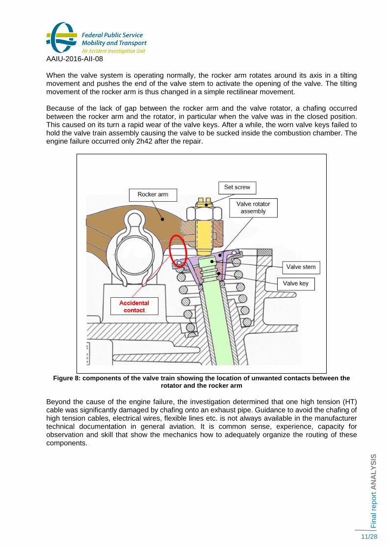
When the valve system is operating normally, the rocker arm rotates around its axis in a tilting movement and pushes the end of the valve stem to activate the opening of the valve. The tilting movement of the rocker arm is thus changed in a simple rectilinear movement. Because of the lack of gap between the rocker arm and the valve rotator, a chafing occurred between the rocker arm and the rotator, in particular when the valve was in the closed position. This caused on its turn a rapid wear of the valve keys. After a while, the worn valve keys failed to hold the valve train assembly causing the valve to be sucked inside the combustion chamber. The engine failure occurred only 2h42 after the repair.
Figure 8: components of the valve train showing the location of unwanted contacts between the
rotator and the rocker arm
Beyond the cause of the engine failure, the investigation determined that one high tension (HT) cable was significantly damaged by chafing onto an exhaust pipe. Guidance to avoid the chafing of high tension cables, electrical wires, flexible lines etc. is not always available in the manufacturer technical documentation in general aviation. It is common sense, experience, capacity for observation and skill that show the mechanics how to adequately organize the routing of these components.

AAIU-2016-AII-08
Fin
al re
po
rt A
NA
LY
SIS
12/28
2.3 Maintenance performed by the pilot owner
Regulation ((EU) 1321/20143 ) is not applicable to annex II (homebuilt) aircraft. The regulation applicable to French registered home-built aircraft is the Decree of 15 March 2005 of the French Republic regarding the “Restricted Airworthiness Certificate (CNRA). This French regulation allows the owner to perform all maintenance tasks to the aircraft, including engine heavy maintenance. On 5 November 2012, DGAC officially allowed the owner to perform maintenance on his aircraft (Certificat pour l’entretien d’un aéronef de construction amateur). The maintenance tasks on the engine were performed by the owner assisted by a friend. Both have a limited experience and qualification in aviation maintenance. The inadequate routing of the ignition lead found during the investigation and visible before the accident would normally not have been performed by an experienced qualified aviation mechanic. However, the valve anomalies were more difficult to detect.
2.4 Technical documentation
A few days after the accident, the engine manufacturer was notified by AAIU(Be) via, the German Federal Bureau of Aircraft Accident Investigation (BFU), and a preliminary report was provided on 19 October 2016 describing the factual information collected during the inspection of the engine. This prompted the engine manufacturer to issue on 14 December 2016 two technical bulletins (‘Technische Mitteilung’ or TM) regarding the adjustment of the valves and the testing of the geometry of the rocker arms of different engine types.
Technische Mitteilung Nr. 25 Datum: 14 Dec. 2016
Gegenstand: Kontrolle der Kipphebelgeometrie und der Kontaktflächen zwischen Ventilschaft und Ventileinstellschraube
Subject: Testing of the geometry of the valve-rocker and the contact surface between the valve stem and the set screw.
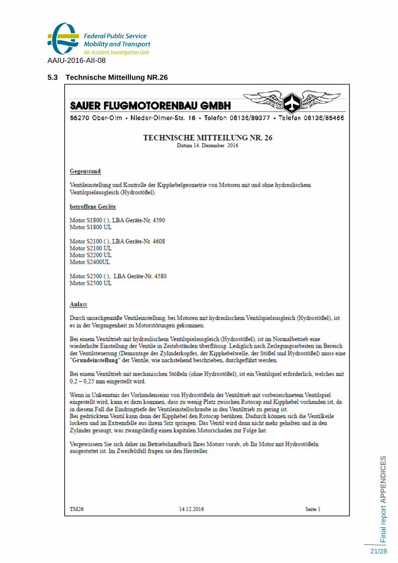
Technische Mitteilung Nr. 26 Datum: 14 Dec 2016
Gegenstand: Ventileinstellung und Kontrolle der Kipphebelgeometrie von Motoren mit und ohne hydraulischem Ventilspielausgleich (Hydrostößel).
Subject: Adjustment of the valve and testing of the geometry of the rocker for motors with or without hydraulic compensation for the valve lash (hydraulic tappet).
These technical bulletins, only released in German language, are enclosed at the end of this report as well as a non-official translation in English made for the purpose of the investigation.
3 Regulation ((EU) 1321/2014 : Commission Regulation of 26 November 2014 on the continuing airworthiness of aircraft and aeronautical products, parts and appliances, and on the approval of organisations and personnel involved in these tasks

AAIU-2016-AII-08
Fin
al re
po
rt A
NA
LY
SIS
13/28
In summary: Technical bulletin Nr 25 requests: 1) To check visually the damage through wear and tear of materials on the contact surface
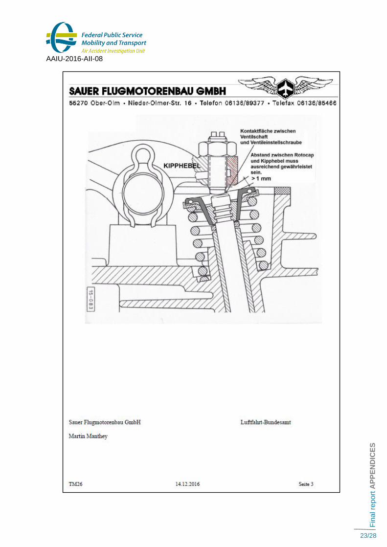
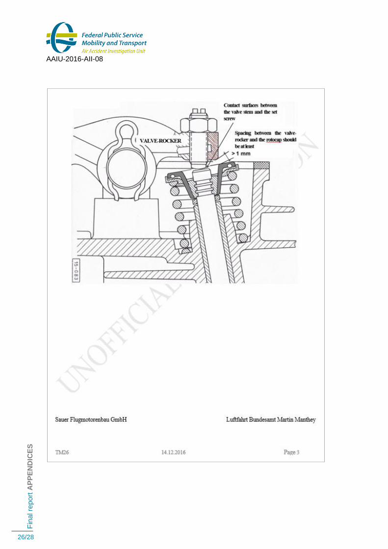
between the set screw and the valve stem. 2) To verify periodically the presence of at least 1 mm gap between the rotator and the valve-
rocker when the valve is pushed in.
Figure 9: Minimum gap between the rocker arm and the rotator (When valve fully pushed in)
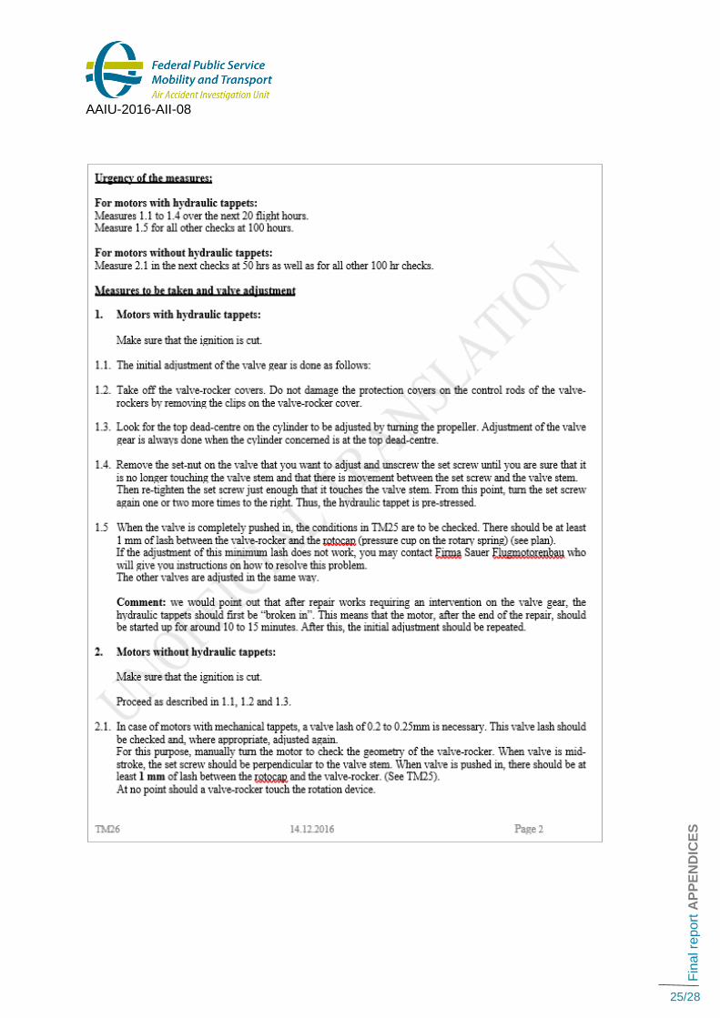
Technical bulletin Nr 26: 1) Reminds that some engine models can be equipped with or without hydraulic tappets implying
that a different procedure must be applied for the valve lash adjustments. 2) Describes the two different adjustment procedures to be used depending on the installed
mechanical tappets or hydraulic tappets. 3) Reminds that the minimum gap between the rotator and the rocker arm must be verified in
accordance with “Technical bulletin Nr 25”.

AAIU-2016-AII-08
Fin
al re
po
rt C
ON
CL
US
ION
14/28
CONCLUSION
3.1 Findings
• The aeroplane was registered in France and was flying under a French Restricted Airworthiness Certificate (CNRA) valid until 13 February 2019.
• The Restricted Airworthiness Certificate (CNRA) is only valid above the French territories unless a written overflight permission is granted by the authority of the overflown foreign country.
• Although the aeroplane was based on the EBGB (Grimbergen) airfield, Permission to Fly over Belgian territory was not granted because this was never requested by the owner.
• The pilot owner held a fitness certificate for the maintenance of his own aircraft delivered by DGAC on 5 November 2012. He regularly performed the routine maintenance of his aeroplane, but lacked experience for the heavy maintenance of the engine and components.
• The pilot-owner did not hold adequate documentation (MM, IPC) for the maintenance and repair of the engine.
• The engine breakdown occurred during the third flight after the replacement of all exhaust valves, 2,7 flight hours after the repair.
• There are indications that the correct adjustment procedure was applied for the adjustment of the valves but an abnormal wear at the stems of the intake valves was not detected.
• The engine failed due to the ingestion of one intake valve inside the combustion chamber of its cylinder. This occurred after an abnormal mechanical contact between the valve rotator and the rocker arm causing the failure of the valve keys.
• The pilot held a valid PPL(A) with a valid SEP(land) class rating.
• During the forced landing, the aeroplane touched down, rebounded and landed again causing the nose landing gear to collapse and the aeroplane to flip over.
3.2 Cause
The direct cause of the accident (the flip-over) is an improper pitch-up attitude (not enough “holding off”) during a forced landing on a soft terrain as a consequence of an engine failure. The engine breakdown (=indirect cause) was due to an insufficient gap between the valve rotators and the rocker arms. This caused an unwanted mechanical contact between these parts followed by a rapid wear of the valve keys ending in the engine failure.
Contributing safety factor:
Performing non-routine maintenance on critical aircraft components without having extensive technical experience. Other safety factor: The lack of technical documentation and/or guidance from the engine manufacturer to warn the mechanics about the “valve stem wear phenomenon”, possibly causing an insufficient gap between the valve rotators and the rocker arms.
AAIU-2016-AII-08
Fin
al re
po
rt S
AF
ET
Y A
CT
ION
S A
ND
RE
CO
MM
EN
DA
TIO
NS
15/28
SAFETY ACTIONS AND RECOMMENDATIONS
4.1 Safety issue: lack of technical documentation
At the time of the accident, no technical documentation and/or guidance from the engine manufacturer existed to warn the mechanics about the valve stem wear phenomenon, possibly causing an insufficient gap between the valve rotators and the rocker arms.
Safety action by the engine manufacturer:
On 14 December 2016, two months after the accident, the engine manufacturer issued two Technical Bulletins regarding the adjustment procedure of the valves and the checking of the geometry of the rocker arms. These bulletins adequately describe the possible issues that led to this engine failure and the appropriate mitigation measures to avoid the reoccurrence of such an engine failure.
AAIU(Be) supports this initiative but encourages the manufacturer to release an English translation of its Technical Bulletins in order to inform as many mechanics as possible.
4.2 Safety factor: Performing an engine repair without having sufficient knowledge/training.
The engine failure occurred soon after an engine repair performed without the support of an appropriate technical documentation. This underlines the importance to have comprehensive data on all kinds of works to be done on an aircraft. Therefore:
Safety message4 to owners performing the maintenance of their aircraft:
Beside the fact that an appropriate skill is required, before deciding to perform maintenance or a repair on your aircraft:
• Make sure that you understand the system of documentation developed by the manufacturer.
• Make sure that you have the most suitable technical documentation for the intended work. As a matter of fact, the manufacturer documentation can be available in several versions depending on the depth of the work to be done (Routine maintenance, overhaul, repair etc).
• Make sure that your technical documentation is up-to-date.
• Check that your technical documentation is complete: the aircraft manufacturer and engine and accessories manufacturers regularly release technical bulletins that focus on specific problems.
• When reading the technical documentation, make sure that you understand it thoroughly. Ask yourself “Do I understand in detail the procedure described in the documentation?”, “Do I understand the reason of the procedure?”, “Does the procedure apply to my case?” etc.
4 Safety message: A message focussing on the existence of a safety factor and the lessons learned. AAIU(Be) can
disseminate a safety message to a community (of pilots, instructors, examiners, ATC officers), an organization or an industry sector for it to consider a safety factor and take action where it believes it appropriate. There is no requirement for a formal response to a safety message, although AAIU(Be) will publish any response it receives.

AAIU-2016-AII-08
Fin
al re
po
rt S
AF
ET
Y A
CT
ION
S A
ND
RE
CO
MM
EN
DA
TIO
NS
16/28
About this report As per Annex 13 and Regulation EU 996/2010, each safety investigation shall be concluded with a report in a form appropriate to the type and seriousness of the accident and serious incident. For this occurrence, a limited-scope, fact-gathering investigation and analysis was conducted in order to produce a short summary report. It is not the purpose of the Air Accident Investigation Unit to apportion blame or liability. The sole objective of the investigation and the reports produced is the determination of the causes, and, where appropriate define recommendations in order to prevent future accidents and incidents.

AAIU-2016-AII-08
Fin
al re
po
rt A
PP
EN
DIC
ES
17/28
APPENDICES
5.1 Technische Mitteillung NR.25

AAIU-2016-AII-08
Fin
al re
po
rt A
PP
EN
DIC
ES
18/28

AAIU-2016-AII-08
Fin
al re
po
rt A
PP
EN
DIC
ES
19/28
5.2 Technical Bulletin Nr 25 (Non official translation in English)

AAIU-2016-AII-08
Fin
al re
po
rt A
PP
EN
DIC
ES
20/28
AAIU-2016-AII-08
Fin
al re
po
rt A
PP
EN
DIC
ES
21/28
5.3 Technische Mitteillung NR.26

AAIU-2016-AII-08
Fin
al re
po
rt A
PP
EN
DIC
ES
22/28
AAIU-2016-AII-08
Fin
al re
po
rt A
PP
EN
DIC
ES
23/28

AAIU-2016-AII-08
Fin
al re
po
rt A
PP
EN
DIC
ES
24/28
5.4 Technical Bulletin Nr 26 (Non official translation in English)
AAIU-2016-AII-08
Fin
al re
po
rt A
PP
EN
DIC
ES
25/28
AAIU-2016-AII-08
Fin
al re
po
rt A
PP
EN
DIC
ES
26/28

AAIU-2016-AII-08
Fin
al re
po
rt A
PP
EN
DIC
ES
27/28

AAIU-2016-AII-08
Fin
al re
po
rt A
PP
EN
DIC
ES
28/28
Air Accident Investigation Unit - (Belgium) City Atrium
Rue du Progrès 56 1210 Brussels
Phone: +32 2 277 44 33
Fax: +32 2 277 42 60
[email protected] www.mobilit.belgium.be