
SAFETY IN FOCUS - SMC · SAFETY IN FOCUS MACHINERY DIRECTIVE AND ISO 13849 IN PRACTICE....
50
SAFETY IN FOCUS MACHINERY DIRECTIVE AND ISO 13849 IN PRACTICE
Transcript of SAFETY IN FOCUS - SMC · SAFETY IN FOCUS MACHINERY DIRECTIVE AND ISO 13849 IN PRACTICE....

SAFETY IN FOCUSMACHINERY DIRECTIVE AND ISO 13849 IN PRACTICE
Safety_in_Focus.indd 1 17/09/2019 09:46
2
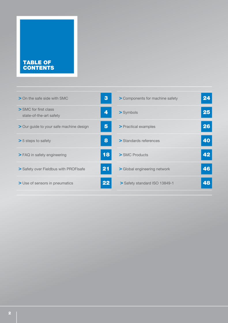
TABLE OF CONTENTS
On the safe side with SMC 3
SMC for first class
state-of-the-art safety4
Our guide to your safe machine design 5
5 steps to safety 8
FAQ in safety engineering 18
Safety over Fieldbus with PROFIsafe 21
Use of sensors in pneumatics 22
Components for machine safety 24
Symbols 25
Practical examples 26
Standards references 40
SMC Products 42
Global engineering network 46
Safety standard ISO 13849-1 48
2
Safety_in_Focus.indd 2 17/09/2019 09:46

3
ON THE SAFE SIDE WITH SMC
Trust us for safety. SMC is a powerful and reliable
partner for factory automation, offering a wide range
of pneumatic solutions. We support our customers to
achieve and maintain the required levels of functional
safety when using our products.
We offer safety products compliant with the Machinery
Directive to provide the necessary levels of risk
reduction to provide a safe working environment for the
operating personnel.
Achieving the required level of functional safety is a
detailed task that can only be undertaken by qualified
engineers. Our global network is there to support this
work by providing the information needed for the best
solution.
The focus is on making machines safer
ON THE SAFE SIDE WITH SMC
Safety_in_Focus.indd 3 17/09/2019 09:46

4
Stand up to the toughest requirements. At SMC,
top priority is given to the development of the highest
quality, innovative products that have excellent
performance.
SMC FOR FIRST CLASS STATE-OF-THE-ART SAFETY
Due to the continuous progress being made in
production and mechanical engineering, safety is
becoming increasingly important. With the introduction
of the Machinery Directive 2006/42/EC, machinery
manufacturers across the world have to comply with
new requirements and harmonised standards in the
design and development of their machines when
delivering products to Europe.
We have many engineers located around the world
in our Technical Centers in Japan, the United States,
Europe and China. Quick, clear and detailed responses
to customer requests are communicated through
our sales group, and our engineers are constantly on
the alert for new trends that lead to new world class
products and solutions.
SMC FIRST CLASS STATE-OF-THE-ART SAFETY
Take advantage of our competence and
the appropriate components for complying
with machine safety standards.
Safety_in_Focus.indd 4 17/09/2019 09:46

5
Safety concepts driven by expertise. In addition to
hazard analysis and risk assessment, a concept for a
safe control system is required.
ISO 13849-1 deals with safety-related components
and their design guidelines for control systems.
OUR GUIDE TO YOUR SAFE MACHINE DESIGN
On the following pages, find out more
about the relationship between the key
considerations and the requirements
in terms of the Machinery Directive
and ISO 13849. SMC is happy to
support you as your competent
partner!
OUR GUIDE TO YOUR SAFE MACHINE DESIGN
Please refer to our website for details of
our latest safety-related components:
www.smcworld.com
Safety_in_Focus.indd 5 17/09/2019 09:46

6
s
Key questions:
THE WAY TO OPTIMAL SAFETY
GUIDELINES & STANDARDS RESEARCH
DEFINITION OF SAFETY CHAIN
1 2
Which potential hazards can
occur with my machine and
how do I evaluate them?
Can this be considered a safety
function? Can the failure of this
function be hazardous to
personnel?
Is my protective equipment
dependent on a control system?
Which safety functions are
suitable for the respective
hazards?
Which performance level does
my risk assessment indicate?
Are design measures enough
to minimise the hazard?
What options do I have
for achieving the required
performance level?
Which components belong to
the safety function?
6
Safety_in_Focus.indd 6 17/09/2019 09:46

7
s
THE WAY TO OPTIMAL SAFETY
SAFETY- RELATEDKEY FIGURES
TECHNICAL
VALIDATION
OUR GUIDE TO YOUR SAFE MACHINE DESIGN
3 4 5
How often will the safety
function be required?
Does the safety system’s service
life correspond to that required
by the standard?
To what extent must I be able to
detect a safety function’s failure?
How do I design a standardised
circuit?
Does a circuit have to be
evaluated by an external
assessor?
What documents do I need for
CE conformity?
In what form must the
documentation exist?
How long must the
documentation be retained for?
Was the required performance
level actually achieved?
Have I completed the activity
based on latest state of the art?
Were all safety principles
properly implemented?
Have I analyzed all the possible
misuses that could be expected?
Does my quality assurance
system comply with the
requirements in the standard?
7
IMPLEMENTA-TION
Safety_in_Focus.indd 7 17/09/2019 09:46

8
5 STEPS TO SAFETYFrom risk assessment to optimal safety function
Safety_in_Focus.indd 8 17/09/2019 09:46

9
With the following 5 steps, we will take you through the entire process from risk assessment to safety function.
Risk assessment Risk reduction The control
system as a
component of
risk reduction
Specification
of the machine's
safety functions
Determination
of the achieved
performance level PL
1 2 3 4 5
5 STEPS TO SAFETY
Safety_in_Focus.indd 9 17/09/2019 09:46

10
CARRYING OUT THE RISK ASSESSMENTAS PER ISO 12100IN A SIMPLIFIED VERSION
Comprehensive safety engineering begins with the
concept and design for the system. Potential hazards
and risks are analysed as per ISO 12100. If elimination
is not possible, then risk reduction is required. This
RISK ASSESSMENT
involves evaluating all of the operating states of the
system: automatic mode, maintenance mode, cleaning,
etc.
FINISH
START
RISK ANALYSIS
RISK ASSESSMENT
No
No
No
No
No
Yes
No
Yes Yes
Yes Yes
Yes
Specify the machine‘s limits and expected use
Identification of hazards
Risk estimation
Risk assessment
Has the risk been
adequately reduced?
Can the risk
be reduced by
technical protective
devices
Risk reduction through
user information
Was the intended
risk reduction achieved?
Was the intended
risk reduction achieved?
Risk reduction through
inherently safe
design
Risk reduction through
technical
protective measures
Documentation
Additional
hazards created?
1
Can the risk be
reduced by inherently
safe design?
Safety_in_Focus.indd 10 17/09/2019 09:46

11
MEASURES FOR RISK REDUCTION
If not all potential risks could be completely
eliminated in step 1, ISO 12100 requires three
further measures for risk reduction. In this case,
the sequence must be strictly observed.
RISK REDUCTION
1 2 3
2
5 STEPS TO SAFETY
INHERENTLYSAFE DESIGN
W Inherent safe design
(example: fixed orifice for
reduction of the cylinder
velocity)
W No trapping hazard/distance
TECHNICALPROTECTIVE MEASURES
W Safety-related systems
W Access systems
W Personnel detection
W Safety-related components, etc.
W Protective covers
W Guards
USER INFORMATIONAND TRAINING
W Signs
W Maintenance plan
W Hazard symbols
W Instructions for use
Safety_in_Focus.indd 11 17/09/2019 09:46

12
If design-related solutions are insufficient for mini-
mising the risk adequately, ISO 12100 requires the
application of protective devices.
The performance requirements of the safety-related
components of a control system for this type of
protective equipment is included in ISO 13849, which
is applicable to pneumatic as well as mechanical,
hydraulic and electronic control systems.
In steps 4 and 5, there is a description of how to
determine the required performance level PLr which
serves as a guideline for the achieved performance
level, PL.
3
THE CONTROL SYSTEM AS A COMPONENT OF RISK REDUCTION
Safety_in_Focus.indd 12 17/09/2019 09:46

135 STEPS TO SAFETY
Now the safety functions need to be specified. This
includes the defining of the actual safety functions –
such as safe positioning, safe venting, prevention of
unexpected start-up or similar – and creating block
diagrams for the safety-related components, as well as
specifying the required reactions in the event of a fault.
A performance level requirement PLr is determined for
each safety function using the risk-graphs.
4
DETERMINING THE MACHINE'S SAFETY FUNCTIONS
Safety_in_Focus.indd 13 17/09/2019 09:46

14
S1: Minor injury
(commonly a reversible injury)
S2: Death or severe injury
(commonly an irreversible injury)
P1
a
b
c
d
e
P1
F1
S1P2
P2
F2
P1
P1
F1
S2P2
P2
F2
PLrP1: Possible under certain
circumstances
P2: Nearly impossible
F1: Seldom to occasionally
F2: Frequently to continuously
F: Frequency and
exposure to hazard
P: Possibility of
avoiding hazard
Level of riskS: Severity of injury
ISO 13849-1 – Risk graph – to define the required Performance Level
4
Safety_in_Focus.indd 14 17/09/2019 09:46

15
W Structure (category)
W MTTFD (Mean Time to Failure dangerous):
Mean time to dangerous failure
W DCavg (Diagnostic coverage average) - Average
diagnostic coverage level
W CCF (Common cause failure): faults with a common
cause
The process marked with blue arrows on the following
double page will assist you with determining the
performance level. Based on the four basic parameters
(category, MTTFD, DC and CCF) it should be deter-
mined that the actual performance level, PL, corre-
sponds to no less than the required performance level
PLr from the risk graph (on page 14).
5
DETERMINING IF THE REQUIRED PERFORMANCE LEVEL PLr IS MET
W Response of safety functions under
fault conditions
W Safety-related software
W Systematic failures
W The capability to execute safety functions under
foreseeable environmental conditions
For the evaluation of the safety related system,
the performance level PL is determined based on
the following:
5 STEPS TO SAFETY
Safety_in_Focus.indd 15 17/09/2019 09:46

16
I: Input device (e. g. sensor)
L: Logic unit (e.g., PLC)
O: Output device (e.g., valve, relays)
m: Monitoring
TE: Test equipment
OTE: Test equipment output
m: Monitoring
C: Cross monitoring
cat. 3: Periodic testing
cat. 4: Testing prior to
every command for a
safety function
MTTFD category 1 is higher than category B,
therefore the probability of a safety function failure
is lower. Nonetheless, a fault can lead to a loss of a
safety function.
In category 2, a fault can lead to the loss of a
safety function between checks and the loss of the
safety function is detected by the check.
In category 3, a single fault does not lead to the
loss of the safety function
In category 4, a single fault is detected at or before
the next demand on the safety function. If that is
not possible then an accumulation of faults shall
not lead to a loss of the safety function.
FeatureCategory
B 1 2 3 4
Design according to relevant standards,withstand the expected operating conditions
X X X X X
Basic safety principles X X X X X
Well-tried safety principles X X X X
Well-tried components X
Mean Time to Dangerous Failure MTTFDlow to
mediumhigh
low to high
low to high
high
Fault detection (Checks) X X X
Single-fault tolerance X X
Consideration of fault accumulation X
Average diagnostic coverage – DCavg none nonelow to
mediumlow to
mediumhigh
Measures against CCF X X X
Mainly characterised by component selection Structure
5
Applicable
for category B
and category 1
Input device Input device Input device
Input device
Output device Output device Output device
Output deviceOutput device
Applicable
for category 2
Applicable
for category 3
and category 4
I I I1
I2
O O O1
OTE O2
mC
m
m
L L L1
TE L2
Safety_in_Focus.indd 16 17/09/2019 09:46

17
1Structure of
hardware
Structure of the safety function (configuration ofI, L, O). The category is comprised of I (input),L (logic) and O (output). 5
leve
ls
B1234
2Lifetime of
components
1 single component
1. MTTFD-value provided by the manufacturer
2. MTTFD determination by ISO 13849-1, Annex C
If the B10D-value is known,the following formula is applied:
*The machine manufacturermust determine the nop value(How many times the part operates in one year)
2 Complete system
3 le
vels
low3 years ormore, less
than 10 years
medium10 years ormore, less
than 30 years
high
30 years ormore, no less
than100 years
3Monitoring the
system
1 single component
Determination of DC by ISO 13849-1, Annex E
Determination of DC via FMEA
2 Complete system
4 le
vels
noneless
than 60 %
low60 % or
more, lessthan 90 %
medium90 % or
more, lessthan 99 %
high99 % or
more
4System
stability
The aim is to achieve no less than 65 points referring to the scoring checklist in ISO 13849-1, Annex F (starting with category 2) 2
leve
ls
noless than65 points
yes65 pointsor more
5 STEPS TO SAFETY
CCF
Category
MTTFD
DCavg
B10D
DC
nop*
MTTFD
MTTFD = 11
MTTFDi∑n
i=1
DCavg = 1
MTTFDi
DCiMTTFDi
∑n
i=1
∑n
i=1
MTTFD = B10D0.1xnop
Category
PL B 1 2 3 4
aMTTFD low
MTTFD MTTFD
b medium MTTFD low MTTFD low MTTFD
c highmedium low medium low
dhigh medium
high high medium MTTFD
e high high
DCavg= without without low medium low medium high
CCF= irrelevant 65 points or more
SMC will provide you with thenecessary safety-related data for calculations.
Safety_in_Focus.indd 17 17/09/2019 09:46

18
An operational function is a function that is
necessary for the machine or equipment to fulfill
its intended purpose. The failure of an operational
function does not result in a loss of safety function.
A safety function is one that the failure and/
or malfunction of which endangers the safety of
persons, but it is not necessary in order for the
machine to function.
FAQ IN SAFETY ENGINEERING
Is it an operational function,
or a safety function?1
Yes, for example pneumatic actuators such as
cylinders can also cause serious injuries, they
are also to be evaluated as per ISO 12100, and if
needed, safe-guarded by design or control-related
measures. Pneumatic or electro-pneumatic controls
must be evaluated and implemented as per ISO
13849-1 and -2.
Do pneumatic components require
a safety-related assessment?2
The safety function “prevention of unexpected start-
up” means that the safety-related system controls
the start-up sequence in such a way as no hazardous
unexpected movements occur. After an energy
outage (compressed air supply, compressor failure or
a hose rupture) and a new start-up, the machine may
not start automatically without receiving a separate
start command.
What does “prevention of unexpected
start-up” mean?
Must I give this aspect consideration?3
The list of safety-principles contained in
ISO 13849-2 contains the following point: “Safe Posi-
tion”, which must be met by safety-related products
and systems. Safe position’ means that a moving
element of a component (eg. spool of valve) is
mechanically retained in a fixed position. Friction only
is not mechanical retention. Normally double solenoid
valves with rubber seal are held in the last position
only by friction; that’s why this principle is not satisfied.
According to safety principles, mechanical retention is
required for Category 1 or higher.
Bi-stable valves are permitted if they have a detent
(mechanical lock) in the final position. Metal-sealed
valves and some special rubber-sealed valves made
by SMC have this type of detent and therefore can be
used in safety-related control systems. In addition, it
should be determined on an application basis whether
unexpected and/or dangerous movements can occur
as the result of a power loss or on machine start-up.
Can bi-stable valves be used in
safety functions?4
Safety_in_Focus.indd 18 17/09/2019 09:46

19FAQ IN SAFETY ENGINEERING 19
No, a two-channel solution must at least be “fail-
safe”, which means that a single failure in the safety
chain (such as failure to activate a valve) cannot re-
sult in the loss of the safety functions. This does not
apply to a cylinder control valve, because a failure in
the spool of the main valve (e.g. contamination that
blocks the spool) can lead to the failure of the entire
system.
No, ISO 13849-2 states that a third-party test is not
required providing the validation process is carried
out by persons independent of the design of the
SRP/CS.
Is a valve, for which both the supply
voltage and separately the pilot air
is interrupted, considered to be a
two-channel solution?
Do products used as safety related
parts of a control system (SRP/CS)
need to be tested or certified by an or-
ganization independent of the manu-
facturer?
5 7
There are a number of possible solutions:
Electrically isolate the power supply to a level of
security that is appropriate to the required PL.
e.g. EX245, EX250, EX260, EX600.
In the case that a safe zone and unsafe zone is
required in the manifold then EX9-PE1-X15/X22/X23
are available.
Fieldbus system using PROFIsafe protocol is also
available e.g. EX245-FPS#-X35. This range of prod-
ucts provides electrical isolation of the valves in up
to three independent zones to Cat4/PL e acc to
EN ISO13849-1, SIL CL3 acc to IEC62061/IEC61508.
Is it possible to safely electrically
isolate the supply to valves that are
manifold mounted?6
Safety_in_Focus.indd 19 17/09/2019 09:46

20
In principle, it can be said that the safety functions
which have electro-pneumatic actuation can also
be carried out purely pneumatically. The cost-
effectiveness of your own safety PLC depends on the
complexity of the desired safety functions and the
related operating functions. Special attention is given
to the sensor technology required in ISO 13849 for
fulfilling the diagnostic coverage level for category 2
and above. To realize this solely with pneumatics would
generally be much more expensive.
SMC will gladly provide you with all safety-related
data, such as B10 and MTTF. In addition, SMC has
a SISTEMA library available. SISTEMA is a program
for the calculation of your safety functions, which
is provided free of charge by the German Institute
for Occupational Safety and Health (Institut für
Arbeitsschutz der Deutschen Gesetzlichen Unfall-
versicherung, IFA). Contact your local sales office
for more information about the SISTEMA library.
A safety-related PLC is very expen-
sive. Can I also carry out my safety
functions purely pneumatically?
Where can I find the safety-related
data of SMC components?8 9
LoTo's ( Lockout-Tagouts) are devices which lock
the control elements of a system – such as switches,
stopcocks, ball valves, etc. – into a specific position.
They are used as prevention of unauthorised
access or unexpected start-up, for example
during a maintenance procedure. If configuration
or maintenance procedures are carried out in a
depressurised state, it is possible to lock an SMC
Pressure Relief 3 Port Valve with Locking Holes (VHS)
in the vented position.
What does a pneumatic
LoTo (Lockout-Tagout) look like?10
20
Safety_in_Focus.indd 20 17/09/2019 09:46

21SAFETY OVER FIELDBUS – EX245 PROFISAFE
SAFETY OVER FIELDBUS WITH PROFISAFE
SMC has a solution for Safety over Fieldbus with the EX245-FPS#-X35, which is a fully certified PROFIsafe
product for use in safety applications up to PL e acc. to EN ISO 13849-1 and SIL 3 acc. to IEC 62061/IEC 61508.
Safe Outputs - 4 power zones
W 3 zones for valve output (8 points for valve output per
zone)
W 1 zone for output module
W Built-in wiring for each power zone, no separate
wiring needed
CONNECTORS – Available with a variety of power
connector & media interfaces
W Copper or fibre optic communications.
W Push/pull or circular power & communications
connectors.
Safe Inputs: 4 input connectors
W single channel: 8 points (SIL2/PLc)
W dual channel: 4 points (SIL3/PLe)
W 2 channels of power supply
GENERAL
W Comprehensive system of diagnostics and
error reporting.
W Same mechanical footprint as existing EX245
PROFINET product series.
W Compatible with EX245 I/O modules and applicable
valve manifolds.
EX245-FPS1-X35
Use with fibre optic cable
EX245-FPS2-X35
Use with copper cable
EX245-FPS3-X35
Use with copper cable
EX245-FPS1/2-X35 EX245-FPS3-X35 EX245-FPS1/2-X35 EX245-FPS3-X35EX245-FPS1/2-X35 EX245-FPS3-X35
Up to 64 pointsPower supply
(24 VDC) Zone 1 Zone 2 Zone 3
Ch1
SafetyOutputs
Ch3 Ch4Ch2
} } } }
Safety_in_Focus.indd 21 17/09/2019 09:46

22
Sensors can be used to determine the state of
a system with regard to pneumatic pressure or
position of valve spools to provide diagnostic feedback
as required for category 2 or above.
USE OF SENSORSIN PNEUMATICS
The supervisory controller (safety PLC) can determine
if a digital or analogue sensor signal changes as
expected within a specific time period.
For example, the final position switch of the respective
cylinder must transmit a change signal within a pre-
defined time period after a valve has been actuated.
Safety_in_Focus.indd 22 17/09/2019 09:46

23
Sensors:
W Position switch
W Pressure switch
W Detection of valve position with pressure switch
Detectable error from the list in ISO 13849-2:
W Change of switching times
W Non-switching or incomplete switch
W Spontaneous change of the initial switching position
(without input signal)
Sensors:
W Blue Line: Valve switching output
W Red Line: Pressure at a pressure switch
W The control system must output a fault if the
pressure does not drop within a predefined time
after switching the valve
Example
Diagram 1
USE OF SENSORS IN PNEUMATICS
Detailed product information can be found in the respective instruction manuals. In addition to the listed information, the observance of legal references found on
page 45 is mandatory.
0
1
t
Safety_in_Focus.indd 23 17/09/2019 09:46

24
As per the Machinery Directive 2006/42/EC, article 2c,
a safety component is a component
W which serves to fulfil a safety function,
W which is independently placed on the market,
W the failure and/or malfunction of which endangers
the safety of persons, and
W which is not necessary in order for the machinery
to function, or for which normal components may
be substituted in order for the machinery to function.
COMPONENTS FOR MACHINE SAFETY Definitions and characteristics
NOTE
The safety component is evaluated by the
component manufacturer in terms of safety
and will be CE marked under the Machinery
Directive. This eliminates the need for an
additional validation process to be carried out by
the safety system designer as per ISO 13849-2.
For safety-related control, standard components
as well as safety components can be installed as
decided by the safety system designer. However,
this must be evaluated during the course of the
system analysis.
COMPONENTS FOR MACHINE SAFETY
Safety_in_Focus.indd 24 17/09/2019 09:46

25
THE EMERGENCY STOP FUNCTION
Every machine must be equipped with
an emergency shutdown function.
It provides the opportunity to place the machine
in a safe state in a hazardous situation.
SYMBOLSSafety functions and emergency stop
Pneumatic safety functions
Safe stopping and closing Safely reduced pressure
Safe venting Two-hand control
Safe direction Prevention of unexpected
start-up
Safe direction Emergency stop
(extended safety function)
SYMBOLS
Safety_in_Focus.indd 25 17/09/2019 09:46

26
PRACTICAL EXAMPLES
Based on our sample system, there are six practical
examples described, which show not only the basic
considerations, but also tips on implementation.
Please note that the listed standard references are not
intended to be complete, and serve solely as a guide.
The listed performance level is only applicable to the
shown structure. Lifetime parameters, diagnostic
coverage level and supplementary sub-systems
(input and logic units) must be evaluated by a suitably
qualified engineer responsible for the safety of
the machine.
To support the design of your safety
functions, you will find common
practical examples on the following
pages.
PAGE 28
EXAMPLE 1
Safe venting (PL e, cat. 4)
and prevention of unexpected
start-up (PL e, cat. 4)
PAGE 32
EXAMPLE 3
Two-hand control (PL c, cat. 1)
and prevention of unexpected
start-up (PL c, cat. 1)
PAGE 30
EXAMPLE 2
Safe stopping and closing (PL d, cat. 3)
and prevention of unexpected
start-up (PL d, cat. 3)
26
Safety_in_Focus.indd 26 17/09/2019 09:46

27
PAGE 36
EXAMPLE 5
Safe venting (PL c, cat. 1)
and prevention of unexpected
start-up (PL c, cat. 1)
EXAMPLE 3
Two-hand control (PL c, cat. 1)
and prevention of unexpected
start-up (PL c, cat. 1)
PAGE 34
EXAMPLE 4
Safe stopping and closing (PL d, cat. 3) and
prevention of unexpected
start-up (PL d, cat. 3)
PAGE 38
EXAMPLE 6
Safely reduced pressure
(PL b, cat. B)
EXAMPLE 2
Safe stopping and closing (PL d, cat. 3)
and prevention of unexpected
start-up (PL d, cat. 3)
PRACTICAL EXAMPLES 27
Safety_in_Focus.indd 27 17/09/2019 09:46

28
Initial situation
The opening of the protective door must cause
the pneumatic system to be vented. In so doing, no
unexpected machine start-up may occur within the
hazardous area during maintenance procedures.
Information regarding implementation
W The valve's venting capacity must be designed so
that immediately upon entering into the hazardous
area, no further dangerous movement can occur
within the area.
W Downstream to the residual pressure relief valve,
no assemblies may inhibit or delay safe venting
(e.g., by defective downstream components).
W Regular checks of the performance of the system
must be carried out to confirm correct venting capa-
bility.
W The safety component does not require validation
as per ISO 13849-2, because it has already been
validated by the component manufacturer during the
course of the CE conformity process.
Safe venting (PL e, cat. 4) and prevention of unexpected start-up (PL e, cat. 4)
SAFETY FUNCTIONS IN PRACTICE – EXAMPLE 1
Safety Components
Safety_in_Focus.indd 28 17/09/2019 09:47

29
SMC products (also see page 42~45)
Circuit description
The desired "safe venting" safety function as well as
the prevention of unexpected start-up are implemented
by the safety component (1V1 and 1V2) in this
example. The required diagnostic coverage level is
also fulfilled (by 1S1 and 1S2). It must be ensured that
Residual Pressure Release Valve with
Detection of de-energised Position
Item: VP-X538/VP-X585
Residual Pressure Release Valve with
Detection of de-energised Position
Item: VG342-X87
Protected system
Note: in the case that a
soft start function is also
required the VP-X555 is
available.
Manual shut off valve
FRL Safety component
Pressure Relief 3 Port Valve with
Locking Holes
Item: VHS
Residual Pressure Release Valve
with Detection of de-energised
Position
Item: VP-X555
any downstream valves can be vented even in the
event of a power outage or malfunction. For example, a
3-position valve with a closed center position may not
be used.
Door
switchSafety PLC
1S1
1V2
1V1
1S2
PRACTICAL EXAMPLES
Detailed product information can be found in the respective instruction manuals. In addition to the listed information, the observance of legal references found on
page 45 is mandatory.
Block diagram
21
L
1 2
3
IN 3
1V1
1 2
1S1 1S2
3
1V2
3 3
Safety_in_Focus.indd 29 17/09/2019 09:47

30
Initial situation
For the removal of components from the conveyor belt,
the downstream drives should stop safely due to the
interruption of the light curtain. When carrying out work
in the hazardous area it must not be possible for the
machine to unexpectedly start up.
Information regarding implementation
W The Sensors must be installed to be tamper-
proof and require a special tool or access code to
make any adjustments. The distance between
the light barrier and the hazardous area must be
large enough that the safety system can stop the
dangerous actuator in a timely manner, before the
operating personnel enters into the hazardous area.
Safe stopping and closing (PL d, cat. 3) and prevention of unexpected start-up (PL d, cat. 3)
SAFETY FUNCTIONS IN PRACTICE – EXAMPLE 2
W The de-energising of the safety-related valves
shall not be carried out via the standard serial
communication – a safety protocol such as
PROFIsafe or another safety technique should be
used. Refer to FAQ number 6.
W Particularly with the vertical installation of
actuators, which are subject to heavy loads, pilot
operated check valves should be mounted directly
into the cylinder.
W Pilot check valve with state detection can be directly
monitored to avoid the usual need to add a regular
non-cyclic test routine which requires process time
and implementation costs.
W For the pneumatic safety function "Safe stopping
and closing", the cylinder overrun must always be
considered due to air compression.
Safety_in_Focus.indd 30 17/09/2019 09:47

31
SMC products (also see page 42~45)
Circuit description
The first channel of the safety function consists of a
3-position valve (1V1). As shown in the block diagram,
the 3-position valve 1V1 needs the sensors 1S1 and
1S2, in order to achieve the required diagnostic cover-
age level. The second channel consists of a 2-position
valve (1V2) and pilot operated check valves with state
detection (1V3 and 1V4). In this example, the sensors
Pilot check valve
with state detection
Item: XT34-303
Auto switch
Item: D-M9
(1S3 and 1S4) monitor the functions of the second
circuit with components 1V3 and 1V4. Prevention of
unexpected start-up, cat. 3, is realized by the 3-posi-
tion valve with a closed center position and the pilot
operated check valve with state detection. The sensors
1S3 and 1S4 are detecting faults of the whole channel
including 1V2.
Light curtain Safety PLC
1S1 1S2
1V2 1V3
1S3
1V4
1S4
1V1
In the case of valve 1V2, the spool is returned to the OFF position on pressure loss by a mechanical spring. Detailed product information can be found in the
respective instruction manuals. In addition to the listed information, the observance of legal references found on page 45 is mandatory.
PRACTICAL EXAMPLES
Solenoid valve
Item: SY3000/5000/7000
Solenoid valve
Item: SY-X350
Block diagram
IN
12
4
51
2
3
1V1 4
51
2
3
1V2
1 221
1V4
1 221
1V3
1S2 1S1
1S4
1S3
Safety_in_Focus.indd 31 17/09/2019 09:47

32
Initial situation
Crimping between the cylinder piston and the piston
rod is realized by means of a purely pneumatic press
with two-hand control. When the button is released, the
press cylinder will move to the upper final position.
Note
Countries may have specific regulations for industrial
presses, these need to be complied with.
Two-hand control (PL c, cat. 1) and prevention of unexpected start-up (PL c, cat. 1)
SAFETY FUNCTIONS IN PRACTICE – EXAMPLE 3
Information regarding implementation
W When reversing the press tool, the crushing hazard
must be evaluated. Actuating a safety function
should not result in the generation of a new hazard.
The appropriate response in the event of a failure
should be included in the risk analysis.
W EN 574 must be observed with regard to the
distance between both actuation buttons.
W The safety component (1Z1) does not require
validation as per ISO 13849-2, because it has
already been validated by the component
manufacturer during the course of the CE conformity
process.
Safety_in_Focus.indd 32 17/09/2019 09:47

33
SMC products (also see page 42~45)
Circuit description
By pushing both buttons within the required time, a
pneumatic output signal on the two-hand control valve
(1Z1) is generated. Automatic reverse is realized by
Two-hand control valve
Item: VR51
means of a pneumatically controlled 2 position valve
(1V3), which returns to home position after the pilot
signal is removed.
1Z1 1V3
PRACTICAL EXAMPLES
Manual valve
Item: VM
In the case of valve 1V3, the spool is returned to the OFF position on pressure loss by a mechanical spring.
Block diagram
1V21V1
5 Port Air Operated Valve
1V4
21
21IN 21
14
4
51
2
3
1V3
1 2
21
IN
OUT
1Z1
IN
1V4
1V2
1V1
Safety_in_Focus.indd 33 17/09/2019 09:47

34
Initial situation
It must not be possible to open the packaging
machine's protective guarding, until all pneumatic
drives are at a standstill.
Safe stopping and closing (PL d, cat. 3) and prevention of unexpected start-up (PL d, cat. 3)
SAFETY FUNCTIONS IN PRACTICE – EXAMPLE 4
Information regarding implementation
W The protective guard remains closed by means of
a dual-channel lock until the drive has come to a
standstill.
W For the vertical installation of actuators, appropriate
measures against possible hose breakage must be
taken,
e. g. using metal piping.
Safety_in_Focus.indd 34 17/09/2019 09:47

35
SMC products (also see page 42~45)
Circuit description
As shown in the block diagram, the first channel, which
is realized by means of the 3-position valve (1V1),
needs the respective sensors (1S4 und 1S3) to achieve
the required diagnosis coverage level.
The second channel, consists of two valves (1V2
and 1V3), which are directly linked to the cylinder. In
contrast to example 2, by using valves that can be
Solenoid valve
Item: SY
Digital pressure sensor
Item: PS1000
Safe stopping and closing (PL d, cat. 3) and prevention of unexpected start-up (PL d, cat. 3)
monitored, regular functional testing of the solenoid
valves can be omitted. In this example, the spool
detection integrated in the valves (1S1 and 1S2)
monitors the functions of the second circuit. Safe
stopping and closing and prevention of unexpected
start-up in category 3 is realized by the 3-position valve
with a closed center position and the two solenoid
valves with spool position detection.
Light curtain Safety PLC
1S4 1S3
1V2 1V3
1V1
1S1 1S2
In the case of valve 1V2, and 1V3 the spool is returned to the OFF position on pressure loss by a mechanical spring.
PRACTICAL EXAMPLES
Block diagram
Solenoid valve
with indirect monitoring
Item: SY-X30
IN
4
51
2
3
1V3 1S24
51
2
3
1V2 1S1
12
4
51
2
3
1V1
1S4 1S3
Safety_in_Focus.indd 35 17/09/2019 09:47

36
Initial situation
If the operator enters into the hazardous area marked
in red, the robot should stop and the pneumatic system
should vent safely. The hazardous area is monitored
using a laser scanner. In this example the safety re-
quirements for the robot must also be evaluated.
Safe venting (PL c, cat. 1) and prevention of unexpected start-up (PL c, cat. 1)
SAFETY FUNCTIONS IN PRACTICE – EXAMPLE 5
Information regarding implementation
W The valve's venting capacity must be designed so
that immediately upon entering into the hazardous
area, no further dangerous movement can occur
within the area.
W Downstream to the residual pressure relief valve,
no assemblies may inhibit or delay safe venting.
W Regular checks of the performance of the system
must be carried out to confirm correct venting capa-
bility.
Safety_in_Focus.indd 36 17/09/2019 09:47

37
SMC products (also see page 42~45)
Circuit description
The valve 1V1, vents the single channel system.
Diagnostics are not required for category 1.
Soft start-up valve
Item: AV-A
Protected system
Pilot poppet valve
Item: VP542Y
1V1
Detailed product information can be found in the respective instruction manuals. In addition to the listed information, the observance of legal references found on
page 45 is mandatory.
PRACTICAL EXAMPLES
Block diagram
Note: in the case that a soft
start function is also required
the AV soft start valve is
available.
Pressure Relief 3 Port Valve with
Locking Holes
Item: VHS
IN21
L
1V1
1 2
3
1 2
3
Safety_in_Focus.indd 37 17/09/2019 09:47

38
Initial situation
During normal operation if the operator enters the
hazardous area monitored by the laser scanner
then the robot movement is stopped. In the case of
maintenance mode the additional hazard due to the
pneumatic system needs to be evaluated.
Safely reduced pressure (PL b, cat. B)
SAFETY FUNCTIONS IN PRACTICE – EXAMPLE 6
Information regarding implementation
W In maintenance mode the pneumatic system
pressure needs to be reduced to a safe level to
reduce the crushing hazard of the actuator.
W In applications with large lateral forces the sizing
is often based on resistance to lateral forces of the
bearing of the cylinder. This can result in oversizing
of the cylinder and increased risk due to the larger
thrust force.
Safety_in_Focus.indd 38 17/09/2019 09:47

39
SMC products (also see page 42~45)
Circuit description
The supply to the cylinder is switched (circuit not
shown) to a secondary circuit with a tamper-proof
regular installed (1Z1). Tamper-proof knob cover is
required for the regulator.
Knob Cover
Item: AR**P-580AS
Pressure relief 3-port valve
with locking holes
Item: VHS
Precision Regulator
Item: IR
1Z1
Regulator
Item: AR-B
Detailed product information can be found in the respective instruction manuals. In addition to the listed information, the observance of legal references found on
page 45 is mandatory.
PRACTICAL EXAMPLES
Block diagram
Safety_in_Focus.indd 39 17/09/2019 09:47

40
Standards referencesSAFETY FUNCTIONS IN PRACTICE
Standards
EN ISO 12100 Safety of machinery - General principles for design - Risk assessment and risk reduction
EN ISO 13849-1 Safety of machinery - Safety-related parts of control systems - Part 1: General principles for design
EN ISO 13849-2 Safety of machinery - Safety-related parts of control systems - Part 2: Validation
EN ISO 13857 Safety of machinery - Safety distances to prevent hazard zones being reached by upper and lower limbs
EN 1037 Safety of machinery - Prevention of unexpected start-up
EN ISO 4414 Pneumatic fluid power - General rules and safety requirements for systems and their components
EN 574 Safety of machinery - Two-hand control devices - Functional aspects - Principles for design
EN ISO 13850 Safety of machinery - Emergency stop function - Principles for design
ISO 1219-1 Fluid power systems and components - Graphical symbols and circuit diagrams - Part 1: Graphical symbols
EN ISO 13855 Safety of machinery - Positioning of safeguards with respect to the approach speeds of parts of the human body
EN 60204-1 Safety of machinery — Electrical equipment of machines — Part 1: General requirements
The list of standards is not intended to be exhaustive.
The machine manufacturer determines the applicable standards during the process of risk assessment for the machine.
Safety_in_Focus.indd 40 17/09/2019 09:47

41
Standards
EN ISO 12100 Safety of machinery - General principles for design - Risk assessment and risk reduction
EN ISO 13849-1 Safety of machinery - Safety-related parts of control systems - Part 1: General principles for design
EN ISO 13849-2 Safety of machinery - Safety-related parts of control systems - Part 2: Validation
EN ISO 13857 Safety of machinery - Safety distances to prevent hazard zones being reached by upper and lower limbs
EN 1037 Safety of machinery - Prevention of unexpected start-up
EN ISO 4414 Pneumatic fluid power - General rules and safety requirements for systems and their components
EN 574 Safety of machinery - Two-hand control devices - Functional aspects - Principles for design
EN ISO 13850 Safety of machinery - Emergency stop function - Principles for design
ISO 1219-1 Fluid power systems and components - Graphical symbols and circuit diagrams - Part 1: Graphical symbols
EN ISO 13855 Safety of machinery - Positioning of safeguards with respect to the approach speeds of parts of the human body
EN 60204-1 Safety of machinery — Electrical equipment of machines — Part 1: General requirements
STANDARD REFERENCES
Safety_in_Focus.indd 41 17/09/2019 09:47

42
SMC PRODUCTSSafety components
Residual pressure relief valve
with direct monitoring
Safety valve as per 2006/42/EC
For max. cat. 2
Item:
VP-X536
Residual pressure relief valve
with direct monitoring
Safety valve as per 2006/42/EC
For max. cat. 4
Mountable with SMC FRL units
Item:
VP-X538
Residual pressure relief valve
with direct monitoring and soft
start function.
Safety valve as per 2006/42/EC
For max. cat. 4
Mountable with SMC FRL units
Gradual pressure increase
Item:
VP-X555 / VP-X585
Residual pressure relief valve
with direct monitoring
Safety valve as per 2006/42/EC
For max. cat. 4
Item:
VG342-X87
Two-hand control valve
Safety valve as per 2006/42/EC
Cat. 1 type IIIA as per EN 574
Item:
VR51
Safety over Fieldbus with PROFIsafe
Safety over Fieldbus with
PROFIsafe: EX245 PROFIsafe
Certified PROFIsafe product for use in safety
applications up to PL e acc. to EN ISO 13849-1
and SIL 3 acc. to IEC 62061 / IEC 61508Item:
EX245-FPS#-X35
Safety_in_Focus.indd 42 17/09/2019 09:47

43SMC PRODUCTS
Recommended SMC products validated according to ISO13849
3/5 Port solenoid valve
SY Series
3/5 Port solenoid valve
SY Series
Solenoid valve
JSY Series
3 port 2-position directly
actuated poppet valve
VT(0)307 Series
Pilot poppet valve
VP Series
Mechanical valve
VM100-A(-30, -32, -33) Series
Mechanical valve
VM200-A(-30, -32, -33) Series
Mechanical valve
VM1000 Series
Mechanical valve
VZM500(-08, -34, -36, -37) Series
Shuttle valve
VR12x0(F) Series
Shuttle valve
VR1211F Series
Safety_in_Focus.indd 43 17/09/2019 09:47

44
Recommended SMC products validated according to ISO13849
Shut off valve
VHS Series
Residual pressure release valve
KE Series
Pilot operated check valve
with state detection
XT34-303 Series
Check valve with one touch
fitting
AKH Series
Check valve with one touch
fitting
AKB Series
Quick exhaust valve
AQ Series
Speed controller
ASP Series
Check valve
XTO-2571/-1239/-1719 Series
2 port valve
VNB(20,30,40)-X700 Series
Safety_in_Focus.indd 44 17/09/2019 09:47

45
Recommended SMC products validated according to ISO13849
Regulator
AR-A/-B Series
Soft start up valve
AVxxxx -A-X2004 Series
Precision regulator
IR1000-AV2000-A/3000-A Series
Vacuum regulator
IRV10(A)/20(A) Series
High purity chemical valve
LVA / LVC Series
SMC PRODUCTS
LEGAL INFORMATION
The circuit examples shown introduce sample applications for our
products and assemblies, with which various pneumatic sub-
systems for safety functions can be realised.
The circuits are merely examples for the listed safety functions, and
do not represent a binding solution or application recommendation
for a specific application. Even if a similar type of safety function
is being assessed, it is not guaranteed that the existing risk can be
adequately reduced by this example in a real application (see
Chapter 5.5, EN ISO 12100). The machine manufacturer or control
system integrator is solely responsible for testing independently
each individual application, and if required, to make additions or
changes to the circuits. In so doing, the machine manufacturer or
control system integrator must independently examine and comply
with all laws, guidelines, standards and product information
pertaining to the design and manufacture of the system and to
observe them during implementation. The machine manufacturer or
control system integrator bear sole responsibility for the suitability of
the circuits for the installed components. SMC assumes no warranty
or liability for an implemented solution designed by the machine
manufacturer or control system integrator for their respective,
specific application, or for the assumption of a sample circuit shown
here for their specific application.
The circuits show only the pneumatic subsystem (control-
component "actuator"). For the completeness of the safety
functions, the machine manufacture or control system integrator
must generally add additional safety-related subsystems (usually
"sensor" and "logic" control components).
NOTE: The PL achieved by the sub-system is directly related to
the overall MTTF and to the average number of cycles of the
component. A greater number of cycles leads to a lower level of PL. D
Safety_in_Focus.indd 45 17/09/2019 09:47

46
JTC (Japan Technical Center) Japan
The Japan Technical Center oversees worldwide
technical development.
The JTC is the center of SMC research and develop-
ment and produces new products for the global market
based on our customers’ current and future needs.
GLOBAL ENGINEERING NETWORKTechnical centers are located in the United States, Europe and China, as well as Japan.
Following the basic concept of developing products
from the customer’s standpoint, SMC dedicates
a large staff to research and development. This is
undertaken to promote research on basic technology
with future potential and to produce products that are
adapted to the needs of the marketplace in a timely
manner. To provide positive and speedy response to
the problems presented by customers throughout the
world, technical centers have been established in the
United States, Europe and China, creating a powerful
global engineering network with Japan as its nucleus.
All of the technical centers share information and
maintain close contact in order to quickly respond to
requirements locally, and to offer the same high quality
of technical service throughout the world.
Safety_in_Focus.indd 46 17/09/2019 09:47

47
CTC (China Technical Center) China
The CTC strengthens the system through product
development and technical services to quickly re-
spond to a wide range of needs and requirements
in the Chinese market.
ETC (European Technical Centre) U.K.
The ETC has been established to support the European
subsidiaries by responding to technical questions,
specifying and designing special products for customer
needs, training their engineers to provide fast local
product support and developing new technology prod-
ucts for modern factory automation.
UTC (US Technical Center) U.S.A.
The UTC is enhancing engineering capabilities to
quickly respond to customers’ needs through prod-
uct development and technical services offered in the
North American market. .
GTC (German Technical Center) Germany
GTC develops products and provides technical ser-
vices by quickly responding to customers’
requirements with a focus on the German market.
GLOBAL ENGINEERING NETWORK
Safety_in_Focus.indd 47 17/09/2019 09:47

48
SAFETY STANDARD ISO 13849-1The globalization of the concept of machine safety by international standards is accelerating.
Conforming to international standards
(IEC/ISO standards) is important.
Example: In Europe, the safety requirements of the
Machinery Directive are mandatory and ISO 13849 can
be used to ensure compliance. Equipment that does
not conform to the directive cannot be distributed in
the EU region. This safety concept is also being taken
up globally.
Countries are affected by the contents of the standard
Countries that affect the contents of the standard
Globalization is accelerating
Member countries of the WTO/TBT agreement must
confirm to international standards. The standards
in each country are aligned internationally.
AMERICA (ANSI)
IEC/ISO STANDARDS
EUROPE (EN) CHINA (GB)
JAPAN (JIS)
AUSTRALIA (AS)SOUTH KOREA (KS)
Safety_in_Focus.indd 48 17/09/2019 09:47

49SMC STANDARDS
Symbol or abbreviation Description
a, b, c, d, e Denotation of performance levels
B, 1, 2, 3, 4 Denotation of categories
B10
Number of cycles until 10 % of the components fail
(for pneumatic and electromechanical components)
B10D
Number of cycles until 10 % of the components fail dangerously
(for pneumatic and electromechanical components)
Cat. Category
CCF Common cause failure
DC Diagnostic coverage
DCavg Average diagnostic coverage
CE Conformité Européene (European Conformity)
F, F1, F2 Frequency and/or time of exposure to the hazard
I/O lnputs/Outputs
ISO International Standards Organization
FMEA Failure modes and effects analysis
MTTF Mean time to failure
MTTFD Mean time to dangerous failure
nop Number of annual operations
P, P1, P2 Possibility of avoiding the hazard
PL Performance level
PLr Required performance level
PLC Programmable logic controller
S, S1, S2 Severity of injury
SIL Safety integrity level
SRP/CS Safety-related part of a control system
TE Test equipment
TM Mission Time
T10D Mean time until 10 % of the components fail dangerously
Symbols and abbreviated terms
Safety_in_Focus.indd 49 17/09/2019 09:47

SMC CorporationAkihabara UDX 15F, 4-14-1Sotokanda, Chiyoda-kuTokyo 101-0021 • Japanwww.smcworld.com
P-E
19-1
6
©2019 SMC Corporation All Rights Reserved,
YOUR AUTOMATION PARTNER
Specifications are subject to change without prior notice and any obligation on the part of the manufacturer.
Safety_in_Focus.indd 50 17/09/2019 09:47