Safety Function: Light Curtain with Muting (two sensor L ... · Safety Function: Light Curtain with...
54
Application Technique Safety Function: Light Curtain with Muting (Two Sensor L- type) and Configurable Safety Relay Products: Guardmaster 440C-CR30 Configurable Safety Relay, 440L GuardShield Light Curtain, 42EF RightSight Photoelectric Sensors, 100S-C Safety Contactors Safety Rating: CAT. 4, PLe to ISO 13849-1: 2008 Topic Page Important User Information 2 General Safety Information 3 Introduction 4 Safety Function Realization: Risk Assessment 4 Light Curtain with Muting (two-sensor L-type) Safety Function 5 Safety Function Requirements 5 Functional Safety Description 6 Bill of Material 7 Setup and Wiring 7 Configuration 15 Calculation of the Performance Level 37 Verification and Validation Plan 40 Verification of the Configuration 49 Additional Resources 52
Transcript of Safety Function: Light Curtain with Muting (two sensor L ... · Safety Function: Light Curtain with...

Application Technique
Safety Function: Light Curtain with Muting (Two Sensor L-type) and Configurable Safety RelayProducts: Guardmaster 440C-CR30 Configurable Safety Relay, 440L GuardShield Light Curtain, 42EF RightSight Photoelectric Sensors, 100S-C Safety Contactors
Safety Rating: CAT. 4, PLe to ISO 13849-1: 2008
Topic Page
Important User Information 2
General Safety Information 3
Introduction 4
Safety Function Realization: Risk Assessment 4
Light Curtain with Muting (two-sensor L-type) Safety Function 5
Safety Function Requirements 5
Functional Safety Description 6
Bill of Material 7
Setup and Wiring 7
Configuration 15
Calculation of the Performance Level 37
Verification and Validation Plan 40
Verification of the Configuration 49
Additional Resources 52

Safety Function: Light Curtain with Muting (Two Sensor L-type) and Configurable Safety Relay
Important User Information
Read this document and the documents listed in the additional resources section about installation, configuration, and operation of this equipment before you install, configure, operate, or maintain this product. Users are required to familiarize themselves with installation and wiring instructions in addition to requirements of all applicable codes, laws, and standards.
Activities including installation, adjustments, putting into service, use, assembly, disassembly, and maintenance are required to be carried out by suitably trained personnel in accordance with applicable code of practice.
If this equipment is used in a manner not specified by the manufacturer, the protection provided by the equipment may be impaired.
In no event will Rockwell Automation, Inc. be responsible or liable for indirect or consequential damages resulting from the use or application of this equipment.
The examples and diagrams in this manual are included solely for illustrative purposes. Because of the many variables and requirements associated with any particular installation, Rockwell Automation, Inc. cannot assume responsibility or liability for actual use based on the examples and diagrams.
No patent liability is assumed by Rockwell Automation, Inc. with respect to use of information, circuits, equipment, or software described in this manual.
Reproduction of the contents of this manual, in whole or in part, without written permission of Rockwell Automation, Inc., is prohibited.
Throughout this manual, when necessary, we use notes to make you aware of safety considerations.
Labels may also be on or inside the equipment to provide specific precautions.
WARNING: Identifies information about practices or circumstances that can cause an explosion in a hazardous environment, which may lead to personal injury or death, property damage, or economic loss.
ATTENTION: Identifies information about practices or circumstances that can lead to personal injury or death, property damage, or economic loss. Attentions help you identify a hazard, avoid a hazard, and recognize the consequence.
IMPORTANT Identifies information that is critical for successful application and understanding of the product.
SHOCK HAZARD: Labels may be on or inside the equipment, for example, a drive or motor, to alert people that dangerous voltage may be present.
BURN HAZARD: Labels may be on or inside the equipment, for example, a drive or motor, to alert people that surfaces may reach dangerous temperatures.
ARC FLASH HAZARD: Labels may be on or inside the equipment, for example, a motor control center, to alert people to potential Arc Flash. Arc Flash will cause severe injury or death. Wear proper Personal Protective Equipment (PPE). Follow ALL Regulatory requirements for safe work practices and for Personal Protective Equipment (PPE).
2 Rockwell Automation Publication SAFETY-AT136C-EN-P - January 2016

Safety Function: Light Curtain with Muting (Two Sensor L-type) and Configurable Safety Relay
General Safety Information
Risk Assessments
Contact Rockwell Automation to learn more about our safety-risk assessment services.
Safety Distance Calculations
Non-separating safeguards provide no physical barrier to prevent access to a hazard. Publications that offer guidance for calculating compliant safety distances for safety systems that use non-separating safeguards, such as light curtains, scanners, two-hand controls, or safety mats, include the following:
EN ISO 13855:2010 (Safety of Machinery – Positioning of safeguards with respect to the approach speeds of parts of the human body)
ANSI B11:19 2010 (Machines – Performance Criteria for Safeguarding)
Separating safeguards monitor a moveable, physical barrier that guards access to a hazard. Publications that offer guidance for calculating compliant access times for safety systems that use separating safeguards, such as gates with limit switches or interlocks (including SensaGuard™ switches), include the following:
EN ISO 14119:2013 (Safety of Machinery – Interlocking devices associated with guards - Principles for design and selection)
EN ISO 13855:2010 (Safety of Machinery – Positioning of safeguards with respect to the approach speeds of parts of the human body)
ANSI B11:19 2010 (Machines – Performance Criteria for Safeguarding)
In addition, consult relevant national or local safety standards to assure compliance.
IMPORTANT This application example is for advanced users and assumes that you are trained and experienced in safety system requirements.
ATTENTION: Perform a risk assessment to make sure that all task and hazard combinations have been identified and addressed. The risk assessment can require additional circuitry to reduce the risk to a tolerable level. Safety circuits must consider safety- distance calculations, which are not part of the scope of this document.
ATTENTION: While safety distance or access time calculations are beyond the scope of this document, compliant safety circuits must often consider a safety distance or access time calculation.
Rockwell Automation Publication SAFETY-AT136C-EN-P - January 2016 3

Safety Function: Light Curtain with Muting (Two Sensor L-type) and Configurable Safety Relay
Introduction
Light curtains are used to detect attempted access to a hazardous area. In normal operation, if a light curtain detects an object, it causes the safety system to stop any hazardous motion in the hazardous area. In some applications, it is desirable for product to pass through the light curtain without stopping motion in the hazardous area. This can be done through the use of muting.
Two-sensor L-type muting is used to let product pass through a light curtain without interrupting the normal Run mode of the machinery. Two-sensor L-type muting can be used only at exit points of the hazardous area. Other types of muting can be used for entry points.
This safety function application example explains how to wire and configure a Two-sensor L-type (single-direction) muting system with override and an additional E-Stop function. The system is based on a Guardmaster® 440C-CR30 configurable safety relay.
Safety Function Realization: Risk Assessment
The required performance level is the result of a risk assessment and refers to the amount of the risk reduction to be carried out by the safety-related parts of the control system. Part of the risk reduction process is to determine the safety functions of the machine. In this application, the performance level required (PLr) by the risk assessment is Category 3, Performance Level d (CAT. 3, PLd), for each safety function. A safety system that achieves CAT. 3, PLd, or higher, can be considered control reliable. Each safety product has its own rating and can be combined to create a safety function that meets or exceeds the PLr.
From: Risk Assessment (ISO 12100)
1. Identification of safety functions
2. Specification of characteristics of each function
3. Determination of required PL (PLr) for each safety function
To: Realization and PL Evaluation
4 Rockwell Automation Publication SAFETY-AT136C-EN-P - January 2016

Safety Function: Light Curtain with Muting (Two Sensor L-type) and Configurable Safety Relay
Light Curtain with Muting (two-sensor L-type) Safety Function
This application technique includes three safety functions.
1. Safety-related stop of hazardous motion initiated by a light curtain.
2. Two-sensor L-type muting of a light curtain.
3. Emergency stop of hazardous motion, initiated by an E-Stop button.
Safety Function Requirements
Interrupting the light curtain stops and prevents hazardous motion by removal of power to the motor. The motor then coasts to a stop (Stop Category 0). When the safety system is reset, hazardous motion and power to the motor does not resume until a secondary action occurs (for example, pressing the start button). The light curtain is muted to let automatically-fed material exit the hazardous area through the light curtain. To initiate the muting function per IEC/TS 62046, multiple sensors are configured to detect the material before it interrupts the light curtain. Faults at the light curtain, muting sensors, wiring terminals or safety controller are detected before the next safety demand. The safe distance from the location of the light curtain to the hazard must be established such that the hazardous motion stops before the user can reach the hazard. The safety function in this example is capable of connecting and interrupting power to motors rated up to 9 A, 600V AC.
According to the IEC/TS 62046 technical specification, you can only use a muting function when it is required by the process being performed on the machine. You must make sure that a person cannot remain undetected in the hazardous zone when muting is terminated. Muting can be used to allow access by materials only when safety is maintained by other means, for example, when the presence of a loaded pallet on a conveyor prevents access to the hazardous zone by personnel. Refer to IEC/TS 62046 for additional considerations when applying muting.
Position the reset button outside of the hazardous area where it is possible to view the entire hazardous area.
Position the override switch outside of the cell in a location where it is not possible for someone to reach the hazards inside the zone through the light curtain while operating the switch. The switch must be positioned so that an E-Stop button is within reach. For practical purposes, position it near the reset button.
The safety functions in this application technique each meet or exceed the requirements for Category 3, Performance Level d (CAT. 3, PLd), per ISO 13849-1 and control reliable operation per ANSI B11.19.
Considerations for Safety Distance and Stopping Performance
Based on the selection of a sensor subsystem, the risk assessment determines if a safety distance calculation is required. Typically, a safety distance calculation is required if a non-separating sensor subsystem (such as a light curtain) is selected for the safety function. For moveable separating safeguard systems, the overall system stopping-performance must be calculated, measured, and compared to the calculated/measured access time.
ATTENTION: If it is not possible to view the entire hazardous area, additional safety-rated presence-sensing devices must be used to detect persons in that area, for example, by using a laser scanner or safety mat inside the cell.
Rockwell Automation Publication SAFETY-AT136C-EN-P - January 2016 5

Safety Function: Light Curtain with Muting (Two Sensor L-type) and Configurable Safety Relay
When calculating a compliant safety distance for a non-separating safeguard system, see the Guardmaster 440C-CR30 Configurable Safety Relay User Manual, publication 440C-UM001, which provides the necessary response-time data.
When considering the overall system-stopping performance of a separating safeguard system, see the Guardmaster 440C-CR30 Configurable Safety Relay User Manual, publication 440C-UM001, which provides response time data necessary for calculating a theoretical overall system-stopping performance value in advance of performing actual tests and measurements on the actual system.
The Guardmaster 440C-CR30 Configurable Safety Relay User Manual, publication 440C-UM001, also provides useful guidance regarding the calculation of the safety-system response time.
Functional Safety Description
Hazardous motion is stopped or prevented by interrupting the field of view of the light curtain. The 440L light curtain and two RightSight™ muting sensors are connected to the 440C-CR30 configurable safety relay. The safety outputs of the 440C-CR30 relay control the power to the 100S-C contactor coils. Whenever the 440C-CR30 relay de-energizes the safety contacts, the hazardous motion coasts to a stop (Stop Category 0). The 440C-CR30 relay monitors the status of the 100S-C output contactors via mechanically-linked auxiliary contacts and does not reset unless both sets of main motor contacts are open. After clearing the light curtain, once all safety input signals are correct, no faults are detected, and the reset push button is pressed (for 0.25 to 3.0 seconds) and released, the 440C-CR30 relay turns ON its safety outputs, providing power to the contactor coils. The E-Stop is connected to the 440C-CR30 relay, which uses pulse checking to monitor the E-Stop for actuation and faults. Whenever the E-Stop is actuated (pressed), the 440C-CR30 relay turns OFF its safety outputs, and the hazardous motion is stopped. After releasing the E-Stop button, once all safety input signals are correct, no faults are detected, and the reset push button is pressed (for 0.25 to 3.0 seconds) and released, the 440C-CR30 relay turns ON its safety outputs, providing power to the contactor coils.
If an object of the specified size passes through the muting sensors in the proper sequence, within the configured time interval, then the light curtain function is muted in the 440C-CR30 relay. The object is allowed to continue passing through the light curtain without motion being stopped. Whenever the light curtain is muted, the muting lamp is energized. Muting is terminated as soon as the object leaves the detection area of the light curtain. Two-sensor L-type muting can only be used at exit points.
If the sequence of the change of state of the muting sensors and light curtain is incorrect, or the timing limits are exceeded, the muting function faults. If the light curtain is interrupted while the muting function is faulted, the system de-energizes the redundant pair of 100S-C contactors, causing the hazardous motion to stop.
A mute-dependent override capability is provided to clear objects stuck in the monitored area, for example, if the conveyor stops while the load is blocking the light curtain and the S2-LC synchronization time expires. The override function is engaged by using a key-actuated momentary selector switch and is time-limited.
In summary, when the un-muted light curtain is interrupted (for example, by a person's hand), the contactors de-energize, removing rotational power from the motor. When the light curtain is clear, and the appropriate reset button is pressed, the contactors are energized. When properly muted, the light curtain's field of view can be interrupted without de-energizing the safety contactors. Whenever the light curtain is muted, the muting lamp is energized.
6 Rockwell Automation Publication SAFETY-AT136C-EN-P - January 2016

Safety Function: Light Curtain with Muting (Two Sensor L-type) and Configurable Safety Relay
Bill of Material
This application uses these products.
Setup and Wiring
For detailed information on installing and wiring, refer to the publications listed in the Additional Resources on the back cover.
System Overview
Muting is the temporary, automatic suspension of the protective function of a safeguarding device like a light curtain. Muting lets materials travel through the light curtain without stopping the hazardous motion. To distinguish between material and persons, the system monitors for a certain sequence of events within specific time limitations.
Under normal operation, if an object interrupts the light curtain, the system de-energizes the final control devices, in this case a redundant pair of 100S-C contactors, thus removing electrical power from the motor, which causes the hazardous motion to stop. Stopped is considered to be the safe state.
If the E-Stop is pressed at any point in time, the safety outputs turn off and hazardous motion coasts to a stop (Stop Category 0). The muting and override functions do not affect the E-Stop function.
Cat. No. Description Quantity
440C-CR30-22BBB Guardmaster 440C-CR30 software configured safety relay, PLe SIL 3, 22 Safety I/O, embedded serial port, USB programming port, 2 Plug-in Slots, 24V DC
1
2080-IQ4OB4 4-channel digital input/output combination module 1
440L-P4KL1280YD GuardShield™ safety light curtain, Res 30 mm, Pt Ht 1280 mm, 64 beams, integrated laser alignment 1
889D-F4AC-5 DC Micro (M12), female, straight, 4-pin, PVC cable, yellow, unshielded, 22AWG, 5 meter (16.4 feet) 1
889D-F8AB-5 DC Micro (M12), female, straight, 8-pin, PVC cable, yellow, unshielded, 24AWG, 5 meter (16.4 feet) 1
42EF-P2JBB-F4 PHOTOSWITCH® photoelectric sensor, RightSight, polarized retroreflective, red, DC - light operate, both sink (NPN) and source (PNP), 4-pin DC Micro QD on 152 mm (6in) pigtail
2
889D-F4AC-5 DC Micro(M12), female, straight, 4-pin PVC, yellow, unshielded, 5 m 2
60-2649 60-2649 swivel/tilt mounting bracket 2
92-124 92-124 reflector 2
855EP-G24Y5 Control tower stack light, pre-assembled, 10 cm pole mount with cap, gray housing, 24V AC/DC full voltage, amber steady status indicator
1
800FP-MT44PX02S 800F non-illuminated mushroom operators, twist to release, 40 mm, round plastic (Type 4/4X/13, IP66), red, plastic latch mount, 0 N.O. contact(s), 2 N.C. contact(s), self-monitoring , standard pack
1
800FP-F611PX10 800F push button - plastic, flush, blue, R, plastic latch mount, 1 N.O. contact(s), 0 N.C. contact(s), standard, standard pack
1
800FP-KR21PX20 800F 2 position key selector switch - plastic, spring return from right, left key removal, key code 3825 (standard), 2 N.O. contact block(s), standard pack
1
100S-C09EJ23C MCS 100S-C safety contactor, 9A, 24V DC (with electric coil) 2
Rockwell Automation Publication SAFETY-AT136C-EN-P - January 2016 7

Safety Function: Light Curtain with Muting (Two Sensor L-type) and Configurable Safety Relay
The arrangement of the muting sensors and the light curtain is shown in these illustrations from above and from the side. According to IEC/TS 62046, the muting sensors should be placed high enough so that they can detect the load on the conveyor but not the pallet or unit being used to transport loads. If that is not achievable, you must use other methods so that personnel cannot enter the zone and climb on to the pallet. See the IEC/TS62046 standard for more information.
Figure 1 - System Layout from Above
Figure 2 - System Layout from the Side
When a light curtain is used, additional mechanical protective devices must be installed so that hazardous machine elements cannot be reached by personnel or material without first passing through the protective field of the light curtain. For example, the entire rest of the hazardous cell must be surrounded by expanded metal fencing of sufficient height and/ or interlocked gates, including the area above and beneath the protective area of the light curtain, if it would otherwise be possible for a person to access the hazard through these spaces. Refer to the relevant standards and the GuardShield Type 4 and GuardShield Remote Teach User Manual, publication 440L-UM003, for additional information on how to position the light curtain.
The selection of light curtain model, protective height, resolution, and other specifications is dependent on the results of the risk assessment for the specific application. Refer to the relevant standards and the GuardShield Type 4 and GuardShield Remote Teach User Manual, publication 440L-UM003, for additional information. These factors also affect the safety distance calculation.
IMPORTANT An example calculation is shown in this document, but you must perform a final calculation for your specific application based on the safety system specification as well as the machine stopping time.
Machine
MS1 MS2 LC
Muting Lamp
MaterialConveyor
Mut
ed LC
LC
Machine
Muting Lamp
Conveyor
Mut
ed LC
S1 S2
Material
MachineMS1 MS2
Muting Lamp
Material
Light
Curta
in
Machine
Material
Ligh
t Cur
tain
Muting Lamp
S1 S2
8 Rockwell Automation Publication SAFETY-AT136C-EN-P - January 2016

Safety Function: Light Curtain with Muting (Two Sensor L-type) and Configurable Safety Relay
The timing diagram below shows the correct sequence of operation, beginning in the OFF state. At (A), the reset button is pushed for longer than 0.25 s and released within 3.0 s. As long as the safety inputs are ON when the reset is pressed, the safety outputs turn ON after the reset is released.
To initiate muting, the light curtain must be clear. At (B), the material is detected by sensor 1 (S1) and then at (C) by sensor 2 (S2). The light curtain function is muted and the muting lamp turns ON after sensor 2 is interrupted. The light curtain must be interrupted at (D). The material must be large enough to be detected by both sensors and the light curtain at the same time. As the material continues down the conveyor, sensor 1 must clear (E), then sensor 2 (F), and then the light curtain (G), at which point the muting function ends and the muting lamp turns OFF.
For muting , an N.C.-style configuration is typically used for the muting sensor–it is normally ON, and then turns its output OFF when the target is detected. Because we are using polarized retroreflective sensors, we use the L.O. (Light Operate) PNP output of the sensor for this application example.
Figure 3 - Timing Diagram for Normal Muting Operation.
30 ms < t1 < S1-S2 Synch Time (configurable up to 10 s)30 ms < t2 < S2-LC Synch Time (configurable up to 10 s)t3 < Max Mute Time (configurable)
1
0
1
0
1
0
1
0
1
0
1
0
1
0
Sensor 1
Sensor 2
Light Curtain
Reset
Muting Active
Output
Muting Lamp
t1
t2
t1
t2
t3
A B C D E F G
Light Curtain (LC)
Reset
Muting Active
Output
Muting Lamp
Sensor 1 (S1)
Sensor 2 (S2)
Rockwell Automation Publication SAFETY-AT136C-EN-P - January 2016 9

Safety Function: Light Curtain with Muting (Two Sensor L-type) and Configurable Safety Relay
If the sequence of the changes of state of the muting sensors and light curtain is incorrect, or the timing limits are exceeded, the muting function faults. If the light curtain is interrupted while the muting function is faulted, the system de-energizes the redundant pair of 100S contactors, causing the hazardous motion to stop.
The most common type of muting fault occurs when the conveyor stops while the material is in the muting area, and either the synchronization time or the maximum muting time elapses. If the light curtain is subsequently interrupted, the conveyor stops. This operation makes it difficult to clear the material out of the light curtain detection area and resume normal operation. Safety standards recommend keeping the configured maximum muting time as short as possible for normal operation, so it is not appropriate to lengthen the maximum muting time just to avoid this timing fault. Therefore, it is more appropriate to design the standard control system so that the conveyor is unlikely to have a standard stop during muting. A mute-dependent override capability is provided to clear objects stuck in the monitored area. The override function is engaged by using a momentary selector switch and is time limited. In this application example, we use a key- operated switch to discourage the use of the override for anything other than its intended purpose.
10 Rockwell Automation Publication SAFETY-AT136C-EN-P - January 2016

Safety Function: Light Curtain with Muting (Two Sensor L-type) and Configurable Safety Relay
The following timing diagram shows the override sequence in the context of an S2-LC Synchronization Time fault, beginning in the OFF state. At (A), we push and release the reset. As long as the safety inputs are ON when the reset is pressed, the safety outputs turn ON after the reset is released. The material is detected by muting sensor 1 and then at (B) by sensor 2, at which point the light curtain function is muted and the muting lamp turns ON. At this point in time, the standard control system stops the conveyor and the load does not interrupt the light curtain within the configured S2- LC Synchronization Time, causing the muting function to fault at (C). The muting lamp begins flashing at 1 Hz. Because the light curtain is still clear, the safety outputs are still ON. The standard control system starts the conveyor. The load blocks the light curtain at (D). Because the muting function is faulted, blocking the light curtain causes the safety outputs to turn OFF, causing the hazardous motion, including the conveyor, to stop. The operator views the hazardous area to confirm there are no people inside and then actuates the override key switch at (E). Three seconds after the override is engaged, the override function turns ON at (F). The muting lamp, which was previously flashing at 1 Hz to indicate the fault, begins flashing at 3 Hz to indicate the override. Because we are utilizing a manual-monitored reset, we must push the reset button to turn ON the safety outputs (G). Once the safety outputs are ON, the conveyor can move forward to clear the material out of the detection area. In this application, we have configured the maximum override time to be 20 seconds. If the light curtain was still interrupted after the time elapsed, or after the override switch was released, the safety outputs would turn OFF. It is possible to initiate a second override sequence by releasing the override switch (turning it OFF) and then turning it back ON, but this requires a reset
Figure 4 - Timing Diagram for Override Function.
If t1 > S2-LC Synch Time, muting function faultst2 = S2-LC Synch Timet3 = 3 seconds (fixed)t4 <= Max Override Time
1
0
1
0
1
0
1
0
1
0
1
0
1
0
Sensor 1
Sensor 2
Light Curtain
Reset
Override
Output
Muting Lamp
t1
t3
t4
A B C D E F G
t2
H I
Override
Sensor 1 (S1)
Sensor 2 (S2)
Light Curtain (LC)
Reset
Output
Muting Lamp
Rockwell Automation Publication SAFETY-AT136C-EN-P - January 2016 11

Safety Function: Light Curtain with Muting (Two Sensor L-type) and Configurable Safety Relay
Safety Distance Calculation
A safety light curtain provides no physical barrier between a person and the hazardous motion. The safety light curtain must be installed at a sufficient distance from the hazardous motion to make sure that someone putting a hand through the light curtain cannot reach the hazard before it has stopped. This distance is referred to as the Safety Distance. The Safety Distance (S or Ds) required varies from installation to installation and therefore must be calculated for each specific application. This application example shows example calculations based on the formula from both the international standard ISO 13855 and ANSI B11:19.
The Safety Distance (S) formula from ISO 13855:
S = (K x T) + CS: minimum distance, in millimeters (mm)K: a parameter, in millimeters per second (mm/s), derived from data on approach speeds of the body or parts of the bodyT: the overall stopping performance in seconds based on the machine stopping time plus the safety system total reaction timeC: the intrusion distance in mm
For the purposes of this example, we use the following values:
K = 1600 mm per secondT = 610 ms [500 ms (Machine Stopping Time) + 20 ms (light curtain) + 45 ms (440C-CR30 relay) + 45 ms (K1 and K2 contactors)]IMPORTANT: The specific machine stopping time must be measured for each application.C = 128 mm [8 x (d-14) but not less than 0 where d is the resolution of the light curtain (d=30 mm)]S = 1600 mm/s x 0.61 s + 8 x (30 -14) = 976 mm + 128 mm = 1104 mm
The light curtain must not be mounted closer than 1104 mm (approx. 43.5 in.) from the hazardous motion being guarded against.
The Safety Distance (Ds) formula from ANSI B11:19 is only slightly different and results in a very similar distance, as follows:
Ds = K x (Ts + Tc + Tr + Tbm) + Dpf.K: the 'standard' hand speed of 63 in. per secondTs: the stop time of the machineTc: the response time of the safety systemTr: the response time of the presence sensing deviceTbm: additional time allowed for the brake monitor (if any) to compensate for variations in normal stopping timeDpf : the distance a 'standard' hand could possibly move through the light curtain before it is detected. This is a fixed value based on the light curtain resolution.
12 Rockwell Automation Publication SAFETY-AT136C-EN-P - January 2016

Safety Function: Light Curtain with Muting (Two Sensor L-type) and Configurable Safety Relay
For the purposes of this example, we use the following values:
K = 63 in. per secondTs = 500 ms (0.5 second) for the purposes of this application example.IMPORTANT: The specific machine stopping time must be measured for each application.Tc = 90 ms = 45 ms (440C-CR30 relay) + 45 ms (K1 and K2 contactors)Tr = 20 ms (light curtain)Tr + Tc = 90 + 20 = 110 ms = 0.11 secondTbm = 0 (No brake is used in this application.)Dpf = 78.7 mm (3.1 in.)Ds = 63 x (0.5 + 0.11) + 3.1 = 41.5 in.
The light curtain must not be mounted closer than 41.5 in. from the guarded hazard.
Rockwell Automation Publication SAFETY-AT136C-EN-P - January 2016 13

Safety Function: Light Curtain with Muting (Two Sensor L-type) and Configurable Safety Relay
Electrical Schematic24V DC - Class 2 DC COM
440C-CR30 Inputs
Override
Transmitter Receiver
Plug-in I/OSlot 2InputsReset
E-Stop
14 Rockwell Automation Publication SAFETY-AT136C-EN-P - January 2016

Safety Function: Light Curtain with Muting (Two Sensor L-type) and Configurable Safety Relay
Configuration
The 42EF RightSight muting sensors do not require configuration. The light curtain uses the standard, default configuration. If it is possible that the configuration DIP switches have been changed, refer to the GuardShield Type 4 and GuardShield Remote Teach User Manual, publication 440L-UM003, for instructions on how to reset them to the default parameters.
Verify that the 440C-CR30 safety relay is running firmware revision 7.00 or later. A free firmware update is available for older units. The 440C-CR30 relay is configured by using Connected Components Workbench™ software, version 7.00 or later. A detailed description of each step is beyond the scope of this document. Knowledge of the Connected Components Workbench software is assumed.
24V DC - Class 2 DC COM
External Switched Stop/Start Circuit
Muting Lamp
440C-CR30 Outputs
Plug-in I/OSlot 2
Outputs
*ISO 13849-2 requires transient suppression across the load as a Basic Safety Principal. The 'EJ' electronic coil provides suitable suppression.
Rockwell Automation Publication SAFETY-AT136C-EN-P - January 2016 15

Safety Function: Light Curtain with Muting (Two Sensor L-type) and Configurable Safety Relay
Configure the 440C-CR30 Relay
Follow these steps to configure the Guardmaster 440C-CR30 relay by using Connected Components Workbench software.
1. In Connected Components Workbench software, choose View and then Device Toolbox.
2. In the Device Toolbox, expand the Catalog section, expand the Safety folder, and then double-click the 440C-CR30 relay to add it to the project.
3. In the Project Organizer, double-click the Guardmaster 440C-CR30 safety relay.
16 Rockwell Automation Publication SAFETY-AT136C-EN-P - January 2016

Safety Function: Light Curtain with Muting (Two Sensor L-type) and Configurable Safety Relay
4. To add the I/O module called for in this circuit, right-click the right-hand plug-in slot of the relay, and choose 2080- IQ4OB4.
TIP The I/O module is shown in standard gray because it is not a safety I/O module. That is permissible in this application because it is not used to connect safety rated signals. Inputs such as Reset buttons and Feedback are not safety rated signals. Using the standard I/O plug-in for these non-safety signals can reserve the limited number of safety inputs and outputs for safety rated signals.
Rockwell Automation Publication SAFETY-AT136C-EN-P - January 2016 17

Safety Function: Light Curtain with Muting (Two Sensor L-type) and Configurable Safety Relay
5. Click Edit Logic to open the function block editor workspace.
Configure the Inputs
Follow these steps to configure the input safety monitoring functions.
1. Click and drag an Emergency Stop Safety Monitoring function (SMF) from the Toolbox to the upper left-hand Safety Monitoring target block in the logic editor.
TIP If you don't see the Toolbox, click View and choose Toolbox.
18 Rockwell Automation Publication SAFETY-AT136C-EN-P - January 2016

Safety Function: Light Curtain with Muting (Two Sensor L-type) and Configurable Safety Relay
Connected Components Workbench software automatically assigns the next available terminals for both the inputs and the test sources. (Changing the terminal assignment for each function is also easy by clicking on them. No terminal changes are required for this application.) Any necessary configuration of those I/O points is also done automatically by the software. In this case, the default assignments are correct.
2. In the Toolbox, click and drag Muting to the target block below the E-Stop, SMF1.
The Muting block, SMF2, consists of the primary input device (the light curtain), the muting function (consisting of two sensor inputs), and the override function. The override function is optional in this block, but we will configure one later. The Muting block consumes three SMF blocks, although it is consolidated to one block visually for simplification. It also consumes one Logic Level A block, which is represented as a Pass Through block.
3. In the Muting block, SMF2, change the Mute Type to 2 Sensor, L-Type by choosing it from the pull-down menu.
Rockwell Automation Publication SAFETY-AT136C-EN-P - January 2016 19

Safety Function: Light Curtain with Muting (Two Sensor L-type) and Configurable Safety Relay
4. On the Muting block, SMF 2, click the third input terminal EI_04 (connected to S1) to view the selection table.
Connected Components Workbench software automatically assigns the next available terminals, EI_02 (Embedded Input 02) through EI_05 for the Light Curtain and Muting Sensors. For this application, the muting sensors are wired into the plug-in module, so we need to change the input terminals.
5. On the input terminal selection table, click Plug-in 2 Inputs 2080-IQ4OB4 terminal 00 to select that input for the muting sensor 1 (S1).
6. On the Muting block, SMF 2, click the fourth input terminal (S2) and assign Plug-in 2 Inputs terminal 01.
With the changes, the Muting block looks like this.
20 Rockwell Automation Publication SAFETY-AT136C-EN-P - January 2016

Safety Function: Light Curtain with Muting (Two Sensor L-type) and Configurable Safety Relay
7. Set the S1-S2 Synch Time and S2-LC Synch Time to values appropriate for your application.
The synchronization times represent the maximum amount of time between the changes of state of the two devices. The value for your application is dependent upon how fast the load is moving through the muting area and the distance between the sensing devices. The maximum setting is 10 seconds. The value is set in 50 ms increments. For this example, we use a setting of five seconds for each synchronization time by selecting a value of 100 (100 x 50 ms = 5000 ms = 5 s).
8. Set the Max. Mute Time Units and Time to values appropriate for your application.
The maximum muting time represents the maximum amount of time that the primary input device (the light curtain) can be muted. Muting starts just after muting sensor 2 detects the load, and the load must clear the light curtain before the maximum muting time elapses. Set the maximum muting time as short as possible based on the requirements of the application. For this example, we use a setting of 20 seconds.
9. To set up the override function, click the + next to Override Settings to expand that section.
Rockwell Automation Publication SAFETY-AT136C-EN-P - January 2016 21

Safety Function: Light Curtain with Muting (Two Sensor L-type) and Configurable Safety Relay
10. Change Disabled to Enabled.
Connected Components Workbench software adds two override (OV) inputs to the Muting block, SMF2, and assigns the next two available terminals as well as Test Source outputs, which are shared with the E-Stop block, SMF1. The default terminal settings are correct for this application.
11. Set the Max. Override Time to a value appropriate for your application.
The maximum override time represents the maximum amount of time that the override function can enable the safety outputs. It should correspond to the amount of time that it would take the load to clear the light curtain in the case of a muting fault. Set the maximum muting time as short as possible based on the requirements of the application. Keep in mind that a second override can be easily engaged by releasing the override switch and then actuating it again. A second reset is also required for a second override. For this example application, we set the time to 20 seconds by selecting a value of 4 (4 x 5 seconds = 20 seconds). The other default Override Settings can remain unchanged.
22 Rockwell Automation Publication SAFETY-AT136C-EN-P - January 2016

Safety Function: Light Curtain with Muting (Two Sensor L-type) and Configurable Safety Relay
12. When complete, the Muting block, SMF2, looks like this, with minor changes for the specific time values of your application.
13. Click the arrow at the bottom of the Muting SMF to minimize the block.
Rockwell Automation Publication SAFETY-AT136C-EN-P - January 2016 23

Safety Function: Light Curtain with Muting (Two Sensor L-type) and Configurable Safety Relay
The minimized SMF block looks like this.
14. To add a Reset safety monitoring function, click and drag a Reset from the Toolbox to the target block below SMF2.
It appears a few rows below the muting block, because the muting block is consuming three of the available SMF blocks.
24 Rockwell Automation Publication SAFETY-AT136C-EN-P - January 2016

Safety Function: Light Curtain with Muting (Two Sensor L-type) and Configurable Safety Relay
15. On the Reset block, SMF 5, click the input terminal EI_02 and choose Plug-in 2 Inputs P2_02.
The reset can come from a standard plug-in input or even via the serial port through a Modbus message.
Configure the Outputs
Follow these steps to add the Safety Output Function (SOF).
1. In the Toolbox under Safety Output Function Blocks, click and drag Immediate OFF to the first Safety Output Function target block.
Connected Components Workbench software automatically assigns the first two available safety output terminals of the 440C-CR30 relay, EO_18 and EO_19 (embedded safety outputs 18 and 19, respectively). These outputs drive the two 100S-C safety contactors. The PT to the right of the terminal assignment stands for Pulse Testing, a technique used to detect if the output terminal is short-circuited to 24V DC or another safety output terminal. Other output terminals have additional options for configuration besides Pulse Testing, but for terminals 18 and 19 it is the only possible configuration.
Rockwell Automation Publication SAFETY-AT136C-EN-P - January 2016 25

Safety Function: Light Curtain with Muting (Two Sensor L-type) and Configurable Safety Relay
2. From the Reset Input pull-down menu, choose SMF5 to use the Reset you configured in the previous section.
3. In the Toolbox, under Safety Output Function Blocks, click and drag Muting Lamp to the next Safety Output Function target block.
Connected Components Workbench software automatically assigns the Mute SMF as SMF 2 and the output terminal as MP_14.
4. Click the output terminal MP_14 and change it to Plug-in 2 Outputs P2_00.
26 Rockwell Automation Publication SAFETY-AT136C-EN-P - January 2016

Safety Function: Light Curtain with Muting (Two Sensor L-type) and Configurable Safety Relay
Configure the Safety Logic
In this application, pushing the Emergency Stop disconnects power from the motor. An interruption of the light curtain, when it is not muted, should also disconnect power from the motor. Using an AND function configures the outputs of the 440C-CR30 relay to turn ON when the E-Stop is closed, that is when the N.C. E-Stop button is released and clear, and the light curtain is clear or muted.
1. In the Toolbox, under the Logic Functions, click and drag an AND logic block onto the first Logic Level B target block.
2. Click the output connection of the E-Stop SMF, which is the blue dot on the right of the block.
The dot turns light gray, indicating that it is selected.
3. Click the first input connection (blue dot) of the AND block to connect it to the E-Stop block.
A connection line appears and both connection dots turn dark gray. Also, a Pass Through block automatically appears in the Logic Level A column.
Rockwell Automation Publication SAFETY-AT136C-EN-P - January 2016 27

Safety Function: Light Curtain with Muting (Two Sensor L-type) and Configurable Safety Relay
The logic looks like this.
4. Click the blue dot on the right of the Mute (SMF2) block, which is the output connection of the Muting SMF Pass Through block LLA 2.
The dot turns light gray, indicating that it is selected.
5. Click the second input connection (blue dot) of the AND block to connect it to the LLA 2 Pass Through block.
A connection line appears and both dots turn dark gray.
28 Rockwell Automation Publication SAFETY-AT136C-EN-P - January 2016

Safety Function: Light Curtain with Muting (Two Sensor L-type) and Configurable Safety Relay
6. Click the output connection, the blue dot on the right of the AND logic block, to select it.
The dot turns light gray.
7. Click the input connection, the blue dot on the left of the Immediate OFF Safety Output Function block, SOF1, to connect it to the AND block.
A connection line appears and both connection dots turn dark gray.
The resulting logic looks like this.
Rockwell Automation Publication SAFETY-AT136C-EN-P - January 2016 29

Safety Function: Light Curtain with Muting (Two Sensor L-type) and Configurable Safety Relay
Configure the Feedback Monitoring
Feedback is the act of monitoring the output device to confirm that it is OFF when the 440C-CR30 relay output driving that device is OFF. Safety-rated output devices, such as safety contactors, use mechanically-linked contacts so that an external device can monitor their status. Mechanical linkage means that all of the contacts are mechanically linked so that when an N.O. contact is closed, the linked N.C. contact is mechanically held open. A 24V DC signal that is sent through the N.C. contact only gets to the 440C-CR30 relay input if the N.C. contact is closed. Therefore, if the 440C-CR30 relay detects 24V DC on input P2_03, the 440C-CR30 relay knows that the main motor contacts (the N.O. channels) are open, and therefore no power is reaching the motor, which is considered a safe state. That portion of the wiring schematic is shown below.
For the 440C-CR30 relay, Feedback Monitoring is configured as a Safety Monitoring Function (SMF) that is subsequently associated with a Safety Output Function (SOF).
1. In the Toolbox, under Safety Monitoring Functions, click and drag Feedback Monitoring to the target block underneath the Reset block.
Connected Components Workbench software automatically assigns the next available terminal. In this application, the feedback monitoring circuit is wired into plug-in input 03, so we need to change the terminal assignment.
24V DC Plug-in I/O Slot 2Inputs
30 Rockwell Automation Publication SAFETY-AT136C-EN-P - January 2016

Safety Function: Light Curtain with Muting (Two Sensor L-type) and Configurable Safety Relay
2. Click the Feedback input terminal EI_06 and change it to Plug-in 2 Inputs 03.
3. To associate this Feedback SMF with the Safety Output Function, on the Immediate OFF SOF, click the pull-down menu next to Feedback and change it from None to SMF 6, which is the Feedback Monitoring block.
TIP To independently monitor each of the redundant contactors, you can connect each to its own input and change the number of inputs on the SMF to 2. This is not necessary for safety, but could simplify troubleshooting in the event of an output device failure.
Rockwell Automation Publication SAFETY-AT136C-EN-P - January 2016 31

Safety Function: Light Curtain with Muting (Two Sensor L-type) and Configurable Safety Relay
The complete logic configuration looks like this.
Configure the Status Indicators
The status indicators on the 440C-CR30 relay can easily be configured per your preference to show more information than typical status indicators.
1. Click the Guardmaster_440C_CR30 Project tab on the Workspace.
2. Click LED Configuration on the lower left.
32 Rockwell Automation Publication SAFETY-AT136C-EN-P - January 2016

Safety Function: Light Curtain with Muting (Two Sensor L-type) and Configurable Safety Relay
3. Configure the Type Filter and Value for each LED as shown in Table 1.
Table 1 - Status Indicator Settings
Input LEDs Type Filter Value Notes
0 Terminal Status Terminal 00 E-Stop Channel 1
1 Terminal Status Terminal 01 E-Stop Channel 2
2 Terminal Status Terminal 02 Light Curtain OSSD A
3 Terminal Status Terminal 03 Light Curtain OSSD B
4-9 Not Used Not Used
Output LEDs Type Filter Value Notes
0 Safety Output Function SOF 1 Safety Outputs 18 and 19
1 Safety Output Function SOF 2 Muting Lamp
2-5 Not Used Not Used
Rockwell Automation Publication SAFETY-AT136C-EN-P - January 2016 33
Safety Function: Light Curtain with Muting (Two Sensor L-type) and Configurable Safety Relay
Confirm the Validity of the Build
Follow these steps to confirm the validity of the logic by using the Build feature in Connected Components Workbench software.
1. Click Guardmaster_440C_CR30 in the bar above the Workspace.
2. Click Build.
A Build Succeeded message confirms that the configuration is valid.
If an error or omission is discovered during a build, a message is displayed that details the error so that it can be corrected. After you correct the error, you need to perform the build again.
Save and Download the Project
Follow these steps to save and download the project.
1. From the File menu, choose Save as to save the project.
2. In the Project Organizer window, double-click Guardmaster_440C_CR30 to open the workspace.
3. Power up the 440C-CR30 safety relay.
4. Connect the USB cable to the 440C-CR30 relay.
IMPORTANT Saving the project with a new name closes the workspace window(s).
34 Rockwell Automation Publication SAFETY-AT136C-EN-P - January 2016
Safety Function: Light Curtain with Muting (Two Sensor L-type) and Configurable Safety Relay
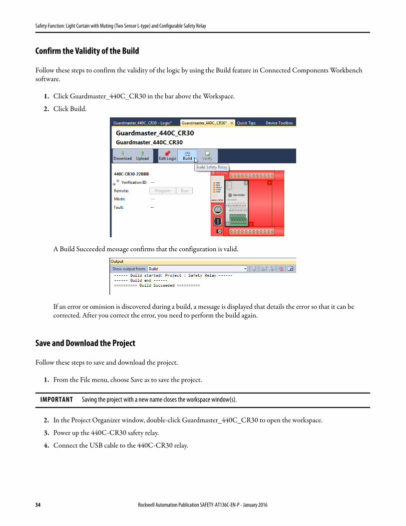
5. Click Download.
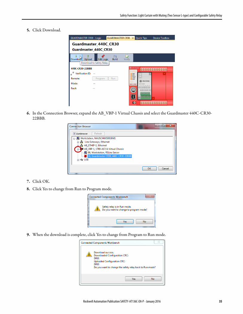
6. In the Connection Browser, expand the AB_VBP-1 Virtual Chassis and select the Guardmaster 440C-CR30-22BBB.
7. Click OK.
8. Click Yes to change from Run to Program mode.
9. When the download is complete, click Yes to change from Program to Run mode.
Rockwell Automation Publication SAFETY-AT136C-EN-P - January 2016 35

Safety Function: Light Curtain with Muting (Two Sensor L-type) and Configurable Safety Relay
10. Click Edit Logic to see the online diagnostics.
Green indicates that a block is True or that an input or output terminal is ON. Flashing green indicates that a Safety Output Function is ready to be Reset. The complete safety system must be installed and powered up to fully utilize the online diagnostics mode.
The online diagnostics mode of the 440C-CR30 relay can be very helpful during the verification process.
11. Review the information in Calculation of the Performance Level on page 37 and Verification and Validation Plan on page 40 before proceeding with Verification of the Configuration on page 49.
36 Rockwell Automation Publication SAFETY-AT136C-EN-P - January 2016

Safety Function: Light Curtain with Muting (Two Sensor L-type) and Configurable Safety Relay
Calculation of the Performance Level
When properly implemented, the light curtain, muting, and E-Stop safety function can achieve a safety rating of Category 4, Performance Level e (CAT. 4, PLe), according to ISO 13849-1: 2008, as calculated by using the SISTEMA software PL calculation tool.
The Performance Level required (PLr) from the risk assessment for each of the safety functions in this application is PLd or better. Additionally each safety function must achieve a CAT. 3 rating or better in order to be considered Control Reliable per ANSI B11.19.
The Performance Level and Category achieved by each subsystem of the light curtain safety function, as calculated by SISTEMA, is shown below.
The light curtain safety function can be modeled as follows.
Input Logic Output
GuardShield Light Curtain
440C-CR30 Relay
100S-C K1
100S-C K2
Subsystem 1 Subsystem 2 Subsystem 3
Rockwell Automation Publication SAFETY-AT136C-EN-P - January 2016 37

Safety Function: Light Curtain with Muting (Two Sensor L-type) and Configurable Safety Relay
The Performance Level and Category achieved by each subsystem of the muting safety function, as calculated by SISTEMA, is shown below.
The muting safety function can be modeled as follows.
The muting function monitors the timing and sequence of both the muting sensors and light curtains. According to Annex E of ISO 13849-1, 99% DC can be claimed based on "Cross monitoring of input signals and intermediate results within the logic (L), and temporal and logical software monitor of the program flow and detection of static faults and short circuits (for multiple I/O)". Essentially the time monitoring and sequential logic of the muting function enable the system to detect faults and claim a high (99%) diagnostic coverage.
The Performance Level and Category achieved by each subsystem of the E-Stop safety function, as calculated by SISTEMA, is shown below.
Input Logic Output
Subsystem 1 Subsystem 2 Subsystem 3 Subsystem 4
GuardShield Light Curtain
440C-CR30 Relay
100S-C K1
100S-C K2
42EF MS1
42EF MS2
38 Rockwell Automation Publication SAFETY-AT136C-EN-P - January 2016

Safety Function: Light Curtain with Muting (Two Sensor L-type) and Configurable Safety Relay
The E-Stop safety function can be modeled as follows.
The Emergency Stop function is considered a complementary protective measure, which is intended to be used in conjunction with other safeguarding measures and protective devices that sufficiently reduce risk. An Emergency Stop is not a substitute for safeguarding measures and shall be designed not to impair the effectiveness of the other protective devices or safety functions.
Due to the single mechanical actuator of the E-Stop, a Fault Exclusion must be considered. In most instances the Fault Exclusion required for electromechanical devices with a single mechanical actuator, such as a typical tongue interlock, limits the Safety Function in which it is included to a maximum Performance Level of PLd; however, the E-Stop is not the primary safeguarding device. It is a complementary measure that is intended for use only in the case of unforeseeable failure or misuse of the machine. The E-Stop's high DC, high MTTFd and Category 4 structure would, Fault Exclusion aside, let the E-Stop Safety Function achieve PLe. It is common practice, due to the E-Stop's complementary function and the high reliability demonstrated in extensive use, to allow the E-Stop to be used in systems requiring PLe.
A Fault Exclusion subsystem has been included in the SISTEMA project to document this consideration.
Because these are electro-mechanical devices, the safety contactor data includes the following:• Mean Time to Failure, dangerous (MTTFd)• Diagnostic Coverage (DCavg)• Common Cause Failure (CCF)
Electro-mechanical devices' functional safety evaluations include the following:• How frequently they are operated• Whether they are effectively monitored for faults• Whether they are properly specified and installed
SISTEMA calculates the MTTFd by using B10d data provided for the contactors along with the estimated frequency of use, entered during the creation of the SISTEMA project.
The DCavg (99%) for the contactors is selected from the Output Device table of ISO 13849-1 Annex E, Direct Monitoring.
The DCavg (99%) for the E-Stop is selected from the Input Device table of ISO 13849-1 Annex E, Cross Monitoring.
Input Logic Output
Subsystem 1 Subsystem 2 Subsystem 3 Subsystem 4
Fault Exclusion
100S-C K1
100S-C K2
E-Stop Channel 1
E-Stop Channel 2
440C-CR30 Relay
Rockwell Automation Publication SAFETY-AT136C-EN-P - January 2016 39

Safety Function: Light Curtain with Muting (Two Sensor L-type) and Configurable Safety Relay
The CCF value is generated by using the scoring process outlined in Annex F of ISO 13849-1. The complete CCF scoring process must be performed when actually implementing an application. A minimum score of 65 must be achieved.
Verification and Validation Plan
Verification and validation play important roles in the avoidance of faults throughout the safety system design and development process. ISO 13849-2 sets the requirements for verification and validation. The standard calls for a documented plan to confirm that all of the safety functional requirements have been met.
Verification is an analysis of the resulting safety control system. The Performance Level (PL) of the safety control system is calculated to confirm that the system meets the required Performance Level (PLr) specified. The SISTEMA software is typically used to perform the calculations and assist with satisfying the requirements of ISO 13849-1.
Validation is a functional test of the safety control system to demonstrate that the system meets the specified requirements of the safety function. The safety control system is tested to confirm that all of the safety-related outputs respond appropriately to their corresponding safety-related inputs. The functional test includes normal operating conditions in addition to potential fault injection of failure modes. A checklist is typically used to document the validation of the safety control system.
Prior to validating the system, confirm that the Guardmaster 440C-CR30 configurable safety relay has been wired and configured in accordance with the installation instructions.
Verification and Validation Checklist
General Machinery Information
Machine Name/Model Number
Machine Serial Number
Customer Name
Test Date
Tester Name(s)
Schematic Drawing Number
Input Devices 800FP-MT44 (E-Stop), 800FP-F611 (Reset), 800FP-KR21 (Override Switch), 440L-P4KL1280YD (Light Curtain), 42EF-P2JBB-F4 (x2) (Photoelectric Sensors)
Configurable Safety Relay 440C-CR30-22BBB
Safety Contactor 100S-C09EJ23C (x2)
Safety Wiring and Relay Configuration
Test Step Verification Pass/Fail Changes/Modifications
1 Confirm that all components' specifications are suitable for the application. Refer to Basic Safety Principles and Well-tried Safety Principles from ISO 13849-2.
2 Visually inspect the safety relay circuit to confirm that it is wired as documented in the schematics.
3 Confirm that the configuration of the 440C-CR30 relay is the correct, intended configuration.
40 Rockwell Automation Publication SAFETY-AT136C-EN-P - January 2016
Safety Function: Light Curtain with Muting (Two Sensor L-type) and Configurable Safety Relay
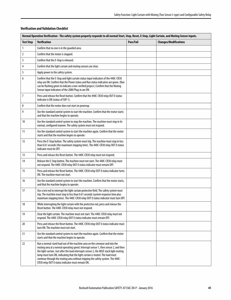
Normal Operation Verification - The safety system properly responds to all normal Start, Stop, Reset, E-Stop, Light Curtain, and Muting Sensor inputs.
Test Step Verification Pass/Fail Changes/Modifications
1 Confirm that no one is in the guarded area.
2 Confirm that the motor is stopped.
3 Confirm that the E-Stop is released.
4 Confirm that the light curtain and muting sensors are clear.
5 Apply power to the safety system.
6 Confirm that the E-Stop and light curtain status input indicators of the 440C-CR30 relay are ON. Confirm that the Power status and Run status indicators are green. (Run can be flashing green to indicate a non-verified project.) Confirm that the Muting Sensor input indicators of the 2080 Plug-in are ON.
7 Press and release the Reset button. Confirm that the 440C-CR30 relay OUT 0 status indicator is ON (status of SOF 1).
8 Confirm that the motor does not start on powerup.
9 Use the standard control system to start the machine. Confirm that the motor starts and that the machine begins to operate.
10 Use the standard control system to stop the machine. The machine must stop in its normal, configured manner. The safety system must not respond.
11 Use the standard control system to start the machine again. Confirm that the motor starts and that the machine begins to operate.
12 Press the E-Stop button. The safety system must trip. The machine must stop in less than 0.61 seconds (the maximum stopping time). The 440C-CR30 relay OUT 0 status indicator must be OFF.
13 Press and release the Reset button. The 440C-CR30 relay must not respond.
14 Release the E-Stop button. The machine must not start. The 440C-CR30 relay must not respond. The 440C-CR30 relay OUT 0 status indicator must remain OFF.
15 Press and release the Reset button. The 440C-CR30 relay OUT 0 status indicator turns ON. The machine must not start.
16 Use the standard control system to start the machine. Confirm that the motor starts, and that the machine begins to operate.
17 Use a test rod to interrupt the light curtain protective field. The safety system must trip. The machine must stop in less than 0.61 seconds (system response time plus maximum stopping time). The 440C-CR30 relay OUT 0 status indicator must turn OFF.
18 While interrupting the light curtain with the protective rod, press and release the Reset button. The 440C-CR30 relay must not respond.
19 Clear the light curtain. The machine must not start. The 440C-CR30 relay must not respond. The 440C-CR30 relay OUT 0 status indicator must remain OFF.
20 Press and release the Reset button. The 440C-CR30 relay OUT 0 status indicator must turn ON. The machine must not start.
21 Use the standard control system to start the machine again. Confirm that the motor starts and that the machine begins to operate.
22 Run a normal-sized load out of the machine area on the conveyor and into the muting area at a normal operating speed. Interrupt sensor 1, then sensor 2, and then the light curtain. Just after the load interrupts sensor 2, the 885E stack light muting lamp must turn ON, indicating that the light curtain is muted. The load must continue through the muting area without tripping the safety system. The 440C-CR30 relay OUT 0 status indicator must remain ON.
Verification and Validation Checklist
Rockwell Automation Publication SAFETY-AT136C-EN-P - January 2016 41

Safety Function: Light Curtain with Muting (Two Sensor L-type) and Configurable Safety Relay
23 Run a normal-sized load out of the machine area on the conveyor and into the muting area at a normal operating speed. Use the standard control system to stop the load while it is interrupting both muting sensors and the light curtain. After 20 seconds (the maximum muting time), the muting lamp must start flashing at 1 Hz to indicate the timing fault. The 440C- CR30 relay OUT 0 status indicator must turn OFF.
24 Use the standard control system to attempt to start the conveyor. The conveyor must not start.
25 Use the key to actuate the override key switch. After three seconds, the muting lamp starts flashing faster (3 Hz) to indicate the override function. Press the Reset button and then use the standard control system to start the conveyor. The conveyor should start, moving the load out of the light curtain field.
26 Continue actuating the override key switch. After 20 seconds (the maximum configured override time), the muting lamp must stop flashing (turn OFF), indicating that the override is no longer active. As long as the light curtain is clear, the conveyor can continue running. Release the override key switch.
27 Run a normal-sized load out of the machine area on the conveyor and into the muting area at a normal operating speed. Use the standard control system to stop the load while it is interrupting the light curtain. After 20 seconds (the maximum muting time), or 5 seconds (the S1-S2 and S2-LC Synch Times) if a muting sensor is not blocked by the load, the muting lamp must start flashing at 1 Hz to indicate the timing fault. The 440C-CR30 relay OUT 0 status indicator must turn OFF.
28 Use the key to actuate the override key switch. After three seconds, the muting lamp starts flashing faster (3 Hz) to indicate the override function. Press the Reset button and then use the standard control system to start the conveyor. The conveyor should start. While the load is still interrupting the light curtain, release the override switch. The 440C-CR30 relay must trip. The 440C-CR30 relay OUT 0 status indicator must turn off. The conveyor must stop. The flashing of the muting lamp slows down (back to 1 Hz), indicating there is no override, but the muting function is still faulted.
29 To clear the light curtain, use the key to actuate the override key switch. After three seconds, the muting lamp starts flashing faster (3 Hz) to indicate the override function. Press the Reset button and then use the standard control system to start the conveyor. The conveyor should start. Release the override after the load has cleared the light curtain. Use the standard control system to stop the conveyor.
30 Confirm that the E-Stop still stops the machine even during the override function. Run a normal-sized load out of the machine area on the conveyor and into the muting area at a normal operating speed. Use the standard control system to stop the load while it is interrupting the light curtain. After 20 seconds (the maximum muting time), the muting lamp must start flashing at 1 Hz to indicate the timing fault. The 440C-CR30 relay OUT 0 status indicator must turn OFF.
31 Use the key to actuate the override key switch. After three seconds, the muting lamp starts flashing faster (3 Hz) to indicate the override function. Press the Reset button and then use the standard control system to start the conveyor. The conveyor should start. While actuating the override switch, push the E-Stop button. The 440C-CR30 relay must trip immediately. The 440C-CR30 relay OUT 0 status indicator must turn OFF. The conveyor must stop.
32 Release the E-Stop. The machine must not start. The 440C-CR30 relay must not respond. The 440C-CR30 relay OUT 0 status indicator must remain OFF.
33 To clear the light curtain, use the key to actuate the override key switch. After three seconds, the muting lamp starts flashing faster (3 Hz) to indicate the override function. Press the Reset button and then use the standard control system to start the conveyor. The conveyor should start. Release the override after the load has cleared the light curtain. Use the standard control system to stop the conveyor.
Verification and Validation Checklist
42 Rockwell Automation Publication SAFETY-AT136C-EN-P - January 2016

Safety Function: Light Curtain with Muting (Two Sensor L-type) and Configurable Safety Relay
34 Confirm muting sensor synchronization times. Run a normal-sized load out of the machine area on the conveyor and into the muting area at a normal operating speed. Use the standard control system to stop the load just after it interrupts muting sensor 1, but before it interrupts muting sensor 2. After five seconds (the maximum S1-S2 Synch Time as configured on the 440C-CR30 relay), the muting lamp must start flashing at 1 Hz to indicate the timing fault. Because the light curtain is clear, the 440C-CR30 relay OUT 0 status indicator remains ON. Use the standard control system to start the conveyor until the load interrupts the light curtain. At this point, the 440C-CR30 relay must trip and the hazardous motion must stop.
35 Use the override key to clear the load from the muting area as documented in step 33.
36 Run a normal-sized load out of the machine area on the conveyor and into the muting area at a normal operating speed. Use the standard control system to stop the load just after it interrupts muting sensor 2, but before it interrupts the light curtain. After five seconds (the maximum S1-S2 Synch Time as configured on the 440C-CR30 relay), the muting lamp must start flashing at 1 Hz to indicate the timing fault. Because the light curtain is clear, the 440C-CR30 relay OUT 0 status indicator remains ON. Use the standard control system to start the conveyor. The conveyor runs until the load interrupts the light curtain. At this point, the 440C-CR30 relay must trip and the hazardous motion must stop.
37 Use the override key to clear the load from the muting area as documented in step 33.
38 Run a normal-sized load out of the machine area on the conveyor and into the muting area at a normal operating speed. Use the standard control system to stop the load just after it clears muting sensor 1 (muting sensor 2 and the light curtain remain interrupted). After five seconds (the maximum S1-S2 Synch Time as configured on the 440C-CR30 relay), the 440C-CR30 relay must trip. The muting lamp must start flashing at 1 Hz to indicate the timing fault.
39 Use the override key to clear the load from the muting area as documented in step 33.
40 Run a normal-sized load out of the machine area on the conveyor, at a normal operating speed, into the muting area, but this time use the standard control system to stop the load just after it clears muting sensor 2 (the light curtain remains interrupted). After five seconds (the maximum S2-LC Synch Time as configured on the 440C-CR30 relay), the 440C-CR30 relay must trip. The muting lamp must start flashing at 1 Hz to indicate the timing fault.
41 Use the override key to clear the load from the muting area as documented in step 33.
Normal Light Curtain Verification
Test Step Verification Pass/Fail Changes/Modifications
1 Confirm that access to the hazardous machine parts is only possible via passage through the protective field of the GuardShield light curtain.
2 Confirm that the distance from the light curtain to any hazard in the cell is greater than the calculated safety distance of the application.
3 Confirm that the optic front cover is not scratched or dirty.
4 Disconnect 24V power from the light curtain and confirm that the 440C-CR30 relay trips.
5 Reconnect 24V power to the light curtain. Push the reset button. Confirm that the 440C- CR30 relay turns its safety outputs ON.
6 Use the test rod included with the light curtain in the original packaging to confirm that the OSSD outputs of the light curtain are OFF when the test rod is anywhere within the light curtain's protective field by observing the status of the output status indicators on the light curtain and the IN 2 and 3 status indicators on the 440C-CR30 relay.
Verification and Validation Checklist
Rockwell Automation Publication SAFETY-AT136C-EN-P - January 2016 43

Safety Function: Light Curtain with Muting (Two Sensor L-type) and Configurable Safety Relay
7 Pass the test rod through the protective field as shown in the illustration. Confirm that the light curtain output status indicators and 440C-CR30 relay input status indicators remain OFF throughout the procedure.
Validation of Safe Response to Abnormal Operation - The safety system responds properly to all foreseeable faults with corresponding diagnostics.
E-Stop - 440C-CR30 Relay Tests
Test Step Validation Pass/Fail Changes/Modifications
1 While the machine is running, remove the E-Stop input wire at terminal EI_00 of the 440C-CR30 relay. The 440C-CR30 relay must trip immediately and stop the machine within 0.5 seconds. The 440C-CR30 relay OUT 0 status indicator must turn OFF. The red Fault status indicator of the 440C-CR30 relay must flash.
2 Reconnect the wire to EI_00. The 440C-CR30 relay must not respond. Press and release the Reset button. The 440C-CR30 relay must not respond.
3 Cycle the E-Stop. The red Fault status indicator should turn OFF.
4 Press and release the Reset button. The 440C-CR30 relay OUT 0 status indicator should turn ON.
5 Use the standard control system to start the machine. Confirm that the motor starts and the machine begins to operate. This step is optional in the following E-Stop and GuardShield validation tests.
6 While the motor is running, jump the E-Stop input wire at terminal MP_12 to terminal EI_00 of the 440C-CR30 relay. The 440C-CR30 relay should not respond.
7 Press the E-Stop. The 440C-CR30 relay must trip immediately. The 440C-CR30 relay OUT 0 status indicator must turn OFF. The red Fault status indicator of the 440C-CR30 relay must flash.
8 Release the E-Stop. Press and release the Reset button. The 440C-CR30 relay must not respond.
9 Remove the jumper. The 440C-CR30 relay must not respond. Press and release the Reset button. The 440C-CR30 relay must not respond.
10 Cycle the E-Stop. The red Fault status indicator should turn OFF.
11 Press and release the Reset button. The 440C-CR30 relay OUT 0 status indicator should turn ON.
12 Short the E-Stop input wire at terminal EI_00 of the 440C-CR30 relay to 24V DC. After approximately five seconds, the 440C-CR30 relay must trip. The red Fault status indicator of the 440C-CR30 relay must flash.
13 Remove the jumper. The 440C-CR30 relay must not respond. Press and release the Reset button. The 440C-CR30 relay must not respond.
14 Cycle the E-Stop. Cycle the Override key switch (because the E-Stop and Override share Test Pulses on MP12 and MP13). The red Fault status indicator should turn OFF.
15 Press and release the Reset button. The 440C-CR30 relay OUT 0 status indicator should turn ON.
Verification and Validation Checklist
Trans
mitt
er
Rece
iver
44 Rockwell Automation Publication SAFETY-AT136C-EN-P - January 2016

Safety Function: Light Curtain with Muting (Two Sensor L-type) and Configurable Safety Relay
16 Short the E-Stop input wire at terminal EI_00 of the 440C-CR30 relay to DC Com (0V DC). The 440C-CR30 relay must trip immediately. The red Fault status indicator of the 440C-CR30 relay turns ON (not flashing).
17 Remove the jumper. The 440C-CR30 relay must not respond. Press and release the Reset button. The 440C-CR30 relay must not respond.
18 Cycle power to the 440C-CR30 relay. After the initial self-checking, the red Fault status indicator should be OFF.
19 Press and release the Reset button. The 440C-CR30 relay OUT 0 status indicator should turn ON.
20 to 40 Repeat steps 1 through 19 using MP_13 for MP_12 and EI_01 for EI_00.
41 Short terminal EI_00 of the 440C-CR30 relay to terminal EI_01. After approximately five seconds, the 440C-CR30 relay must trip. The red Fault status indicator of the 440C-CR30 relay must flash.
42 Remove the jumper. The 440C-CR30 relay must not respond. Press and release the Reset button. The 440C-CR30 relay must not respond.
43 Cycle the E-Stop. The red Fault status indicator should turn OFF.
44 Press and release the Reset button. The 440C-CR30 relay OUT 0 status indicator should turn ON.
Validation of Safe Response to Abnormal Operation - The safety system responds properly to all foreseeable faults with corresponding diagnostics.
Override Switch - 440C-CR30 Relay Tests
Test Step Validation Pass/Fail Changes/Modifications
1 Interrupt the light curtain and at least one muting sensor (use either the normal load or a substitute, such as a piece of cardboard). The light curtain and at least one muting sensor must remain interrupted throughout this section. The 440C-CR30 relay faults either immediately or after the maximum muting time expires (depending on the sequence of the sensor interruption). At that time, the red Fault status indicator of the 440C-CR30 relay flashes and the muting lamp flashes at 1 Hz.
IMPORTANT: Throughout this section, every actuation of the override must be followed by waiting for three seconds for the override function to initiate.
2 Actuate the override key. After three seconds, the muting lamp flashes faster (3 Hz). Press the reset button. The 440C-CR30 relay OUT 0 status indicator turns ON.
3 Immediately remove the override input wire at terminal EI_04 of the 440C-CR30 relay. The 440C-CR30 relay must trip immediately and stop the machine within 0.5 seconds. The 440C-CR30 relay OUT 0 status indicator must turn OFF. The red Fault status indicator of the 440C-CR30 relay must flash.
4 Reconnect the wire to EI_04. The 440C-CR30 relay must not respond. After three seconds, press and release the Reset button. The 440C-CR30 relay must not respond.
5 Cycle the Override and hold it on. After three seconds, the muting lamp flashes faster (3 Hz). The red Fault status indicator continues flashing due to the muting fault, which is independent of the override fault.
6 Press and release the Reset button. The 440C-CR30 relay OUT 0 status indicator should turn ON.
7 Use the standard control system to start the machine. Confirm that the motor starts and that the machine begins to operate. This step is optional in the following Override validation tests.
8 While the motor is running, jump the Override input wire at terminal MP_12 to terminal EI_04 of the 440C-CR30 relay. The 440C-CR30 relay should not respond.
9 Release the Override. The 440C-CR30 relay must trip immediately. The 440C-CR30 relay OUT 0 status indicator must turn OFF. The red Fault status indicator of the 440C-CR30 relay must flash.
Verification and Validation Checklist
Rockwell Automation Publication SAFETY-AT136C-EN-P - January 2016 45

Safety Function: Light Curtain with Muting (Two Sensor L-type) and Configurable Safety Relay
10 Actuate the Override. Press and release the Reset button. The 440C-CR30 relay must not respond.
11 Remove the jumper. The 440C-CR30 relay must not respond. Press and release the Reset button. The 440C-CR30 relay must not respond.
12 Cycle the Override and hold it on. After three seconds, the muting lamp flashes faster (3 Hz).
13 Press and release the Reset button. The 440C-CR30 relay OUT 0 status indicator should turn ON.
14 Short the Override input wire at terminal EI_04 of the 440C-CR30 relay to 24V DC. After approximately five seconds, the 440C-CR30 relay must trip.
15 Remove the jumper. The 440C-CR30 relay must not respond. Press and release the Reset button. The 440C-CR30 relay must not respond.
16 Cycle the E-Stop (because the E-Stop and Override share Test Pulses on MP12 and MP13). Cycle the Override key switch and hold it on.
17 Press and release the Reset button. The 440C-CR30 relay OUT 0 status indicator should turn ON.
18 Short the Override input wire at terminal EI_04 of the 440C-CR30 relay to DC Com (0V DC). The 440C-CR30 relay must trip immediately. The red Fault status indicator of the 440C- CR30 relay turns ON (not flashing).
19 Remove the jumper. The 440C-CR30 relay must not respond. Press and release the Reset button. The 440C-CR30 relay must not respond.
20 Cycle power to the 440C-CR30 relay.
21 to 40 Repeat steps 1 through 20 using MP_13 for MP_12 and EI_05 for EI_04.
41 Short terminal EI_04 of the 440C-CR30 relay to terminal EI_05. After approximately five seconds, the 440C-CR30 relay must trip. The red Fault status indicator of the 440C-CR30 relay must flash.
42 Remove the jumper. The 440C-CR30 relay must not respond. Press and release the Reset button. The 440C-CR30 relay must not respond.
43 Cycle the E-Stop (because the E-Stop and Override share Test Pulses on MP12 and MP13). Cycle the Override key switch and hold it on.
44 Press and release the Reset button. The 440C-CR30 relay OUT 0 status indicator should turn ON.
45 Clear the load (or substitute) from the muting sensors and light curtain. The outputs of those devices turn ON.
46 Press and release the Reset button. The 440C-CR30 relay OUT 0 status indicator should turn ON.
Validation of Safe Response to Abnormal Operation - The safety system responds properly to all foreseeable faults with corresponding diagnostics.
GuardShield Light Curtain - 440C-CR30 Relay Tests
Test Step Validation Pass/Fail Changes/Modifications
1 Keep the light curtain clear. Remove the light curtain OSSD1 wire to terminal EI_02 of the 440C-CR30 relay. The 440C-CR30 relay must trip immediately. The red Fault status indicator of the 440C-CR30 relay must flash.
2 Reconnect the wire to EI_02. The 440C-CR30 relay must not respond. Press and release the Reset button. The 440C-CR30 relay must not respond.
3 Interrupt and the clear the light curtain. The red Fault status indicator should turn OFF.
4 Press and release the Reset button. The 440C-CR30 relay OUT 0 status indicator should turn ON.
Verification and Validation Checklist
46 Rockwell Automation Publication SAFETY-AT136C-EN-P - January 2016
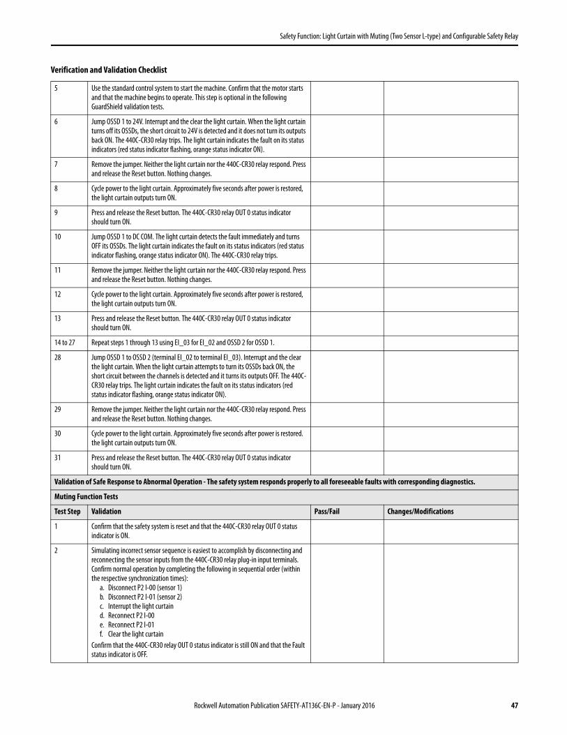
Safety Function: Light Curtain with Muting (Two Sensor L-type) and Configurable Safety Relay
5 Use the standard control system to start the machine. Confirm that the motor starts and that the machine begins to operate. This step is optional in the following GuardShield validation tests.
6 Jump OSSD 1 to 24V. Interrupt and the clear the light curtain. When the light curtain turns off its OSSDs, the short circuit to 24V is detected and it does not turn its outputs back ON. The 440C-CR30 relay trips. The light curtain indicates the fault on its status indicators (red status indicator flashing, orange status indicator ON).
7 Remove the jumper. Neither the light curtain nor the 440C-CR30 relay respond. Press and release the Reset button. Nothing changes.
8 Cycle power to the light curtain. Approximately five seconds after power is restored, the light curtain outputs turn ON.
9 Press and release the Reset button. The 440C-CR30 relay OUT 0 status indicator should turn ON.
10 Jump OSSD 1 to DC COM. The light curtain detects the fault immediately and turns OFF its OSSDs. The light curtain indicates the fault on its status indicators (red status indicator flashing, orange status indicator ON). The 440C-CR30 relay trips.
11 Remove the jumper. Neither the light curtain nor the 440C-CR30 relay respond. Press and release the Reset button. Nothing changes.
12 Cycle power to the light curtain. Approximately five seconds after power is restored, the light curtain outputs turn ON.
13 Press and release the Reset button. The 440C-CR30 relay OUT 0 status indicator should turn ON.
14 to 27 Repeat steps 1 through 13 using EI_03 for EI_02 and OSSD 2 for OSSD 1.
28 Jump OSSD 1 to OSSD 2 (terminal EI_02 to terminal EI_03). Interrupt and the clear the light curtain. When the light curtain attempts to turn its OSSDs back ON, the short circuit between the channels is detected and it turns its outputs OFF. The 440C-CR30 relay trips. The light curtain indicates the fault on its status indicators (red status indicator flashing, orange status indicator ON).
29 Remove the jumper. Neither the light curtain nor the 440C-CR30 relay respond. Press and release the Reset button. Nothing changes.
30 Cycle power to the light curtain. Approximately five seconds after power is restored. the light curtain outputs turn ON.
31 Press and release the Reset button. The 440C-CR30 relay OUT 0 status indicator should turn ON.
Validation of Safe Response to Abnormal Operation - The safety system responds properly to all foreseeable faults with corresponding diagnostics.
Muting Function Tests
Test Step Validation Pass/Fail Changes/Modifications
1 Confirm that the safety system is reset and that the 440C-CR30 relay OUT 0 status indicator is ON.
2 Simulating incorrect sensor sequence is easiest to accomplish by disconnecting and reconnecting the sensor inputs from the 440C-CR30 relay plug-in input terminals. Confirm normal operation by completing the following in sequential order (within the respective synchronization times):
a. Disconnect P2 I-00 (sensor 1)b. Disconnect P2 I-01 (sensor 2)c. Interrupt the light curtaind. Reconnect P2 I-00e. Reconnect P2 I-01f. Clear the light curtain
Confirm that the 440C-CR30 relay OUT 0 status indicator is still ON and that the Fault status indicator is OFF.
Verification and Validation Checklist
Rockwell Automation Publication SAFETY-AT136C-EN-P - January 2016 47

Safety Function: Light Curtain with Muting (Two Sensor L-type) and Configurable Safety Relay
3 Check the system reaction to an incorrect sequence by completing the following in sequential order (within the respective synchronization times):
a. Disconnect P2 I-00 (sensor 1)b. Disconnect P2 I-01 (sensor 2) c. Interrupt the light curtaind. Reconnect P2 I-01 (sensor 2)
Since S1 was interrupted before S2, S1 must clear before S2. As soon as S2 is reconnected (cleared) before S1, the 440C-CR30 relay trips. Confirm that the 440C-CR30 relay OUT 0 status indicator turns OFF and that the red Fault status indicator starts flashing.
4 Reconnect P2 I-00 and clear the light curtain. Press the reset button and confirm that the 440C-CR30 relay OUT 0 status indicator is ON and that the red Fault status indicator is OFF.
Validation of Safe Response to Abnormal Operation - The safety system responds properly to all foreseeable faults with corresponding diagnostics.
Contactor, 440C-CR30 Relay Tests
Test Step Validation Pass/Fail Changes/Modifications
1 While the machine continues to run, break the connection between terminal EO_18 of the 440C-CR30 relay and A1 of the K1 Coil. The hazardous motion must coast to a stop.
2 Press the external Stop button. Restore the connection. Press the external Start button to resume the hazardous motion.
3 While the hazardous motion continues to run, jump the A1 terminal of the K1 coil to 24V. After approximately 18 seconds, the 440C-CR30 relay must trip. K2 must de-energize. The hazardous motion coasts to a stop. The red Fault status indicator LED on the 440C-CR30 relay is ON.
4 Remove the jumper. Press and release the Reset button for the 440C-CR30 relay.The 440C-CR30 relay must not respond.
5 Cycle power to the 440C-CR30 relay. It responds. The red Fault status indicator LED onthe 440C-CR30 relay is OFF.
6 Press and release the Reset button for the 440C-CR30 relay. Press the external Start button. The hazardous motion must resume.
7 While the machine continues to run, short the A1 terminal of the K1 coil to DC COM. The 440C-CR30 relay must trip. The red Fault status indicator LED on the 440C-CR30 relay is ON.
8 Remove the jumper. Press and release the Reset button for the 440C-CR30 relay. The 440C-CR30 relay must not respond.
9 Cycle power to the 440C-CR30 relay. The 440C-CR30 relay responds. The red Fault status indicator LED on the 440C-CR30 relay is OFF.
10 Press and release the Reset button for the 440C-CR30 relay. Press the external Start button. The hazardous motion resumes.
11…20 Repeat steps 1…10 by using EO_19 in place of EO_18 and K2 in place of K1.
21 Jump the A1 terminal of K1 to the A1 terminal of K2. After approximately 18 seconds, the 440C-CR30 relay must trip. The hazardous motion coasts to a stop.The red Fault status indicator LED on the 440C-CR30 relay is ON.
22 Remove the jumper. Press and release the Reset button for the 440C-CR30 relay. The 440C-CR30 relay must not respond.
23 Cycle power to the 440C-CR30 relay. It responds. The red Fault status indicator LED onthe 440C-CR30 relay is OFF.
24 Press and release the Reset button for the 440C-CR30 relay. Press the external Start button. The hazardous motion must resume.
Verification and Validation Checklist
48 Rockwell Automation Publication SAFETY-AT136C-EN-P - January 2016

Safety Function: Light Curtain with Muting (Two Sensor L-type) and Configurable Safety Relay
Verification of the Configuration
You must confirm the verification of the 440C-CR30 configuration for each individual application by using the Verify command in the configuration software. If the 440C-CR30 configuration is not verified, it will fault after 24 hours of operation.
Follow these steps to confirm the verification of the configuration.
1. Make sure the 440C-CR30 relay is powered up and connected to your workstation via the USB cable.
2. Confirm that the upper right-hand corner of the Connected Components Workbench Project tab shows that the 440C-CR30 relay is connected. If it is not, click Connect to Device to establish the software connection.
Validation of Safe Response to Abnormal Operation - The safety system responds properly to all foreseeable faults with corresponding diagnostics.
Contactor Feedback, 440C-CR30 Relay Tests
Test Step Validation Pass/Fail Changes/Modifications
1 While the machine continues to run, remove the K1 feedback connection at terminal P1_03. The machine must continue to run.
2 Press the E-Stop. The safety system must trip. The hazardous motion must stop within less than 0.7 seconds. Monitor the status indicator LEDs for proper operation, and monitor the 440C-CR30 relay for proper status by using Connected Components Workbench software.
3 Release the E-Stop. The machine must not start. The 440C-CR30 relay must not respond. Monitor the status indicator LEDs for proper operation, and monitor the 440C-CR30 relay for proper status by using Connected Components Workbench software.
4 Press and release the Reset button for the 440C-CR30 relay. The 440C-CR30 relay must not respond. Monitor the status indicator LEDs for proper operation, and monitor the 440C-CR30 relay for proper status by using Connected Components Workbench software.
5 Replace the connection at P1_03. Cycle power to the 440C-CR30 relay. Press the Reset button for the 440C-CR30 relay. The 440C-CR30 relay outputs must energize. Press and release the external Start button. Confirm that the motor starts and that the machine begins to operate.
ATTENTION: The verification process should be documented in the safety system's technical file.
Verification and Validation Checklist
Rockwell Automation Publication SAFETY-AT136C-EN-P - January 2016 49

Safety Function: Light Curtain with Muting (Two Sensor L-type) and Configurable Safety Relay
3. Click Verify.
4. Answer all the questions and check each box, if completed.
5. Click Generate.
6. Click Yes to proceed with the verification.
After about ten seconds, a pop-up window will appear to confirm that the Verify process was successful.
7. Click Yes to change to Run mode.
IMPORTANT All of the boxes must be marked in order to Generate the Verification ID.
50 Rockwell Automation Publication SAFETY-AT136C-EN-P - January 2016

Safety Function: Light Curtain with Muting (Two Sensor L-type) and Configurable Safety Relay
8. Record the Safety Verification ID in the machine's documentation.
This process is the feedback to the 440C-CR30 relay that the system verification and functional tests have been completed. The unique verification ID can be used to check if changes have been made to a configuration file. Any change to the configuration removes the Safety Verification ID. Subsequent Verify actions generate a different verification ID. The Safety Verification ID is displayed in Connected Components Workbench software only when you are connected to the 440C-CR30 relay. The Safety Verification ID can be displayed on the IN and OUT input and output status indicators of the 440C-CR30 safety relay at any time by pushing and holding the MEM/ID button below the USB receptacle.
Rockwell Automation Publication SAFETY-AT136C-EN-P - January 2016 51
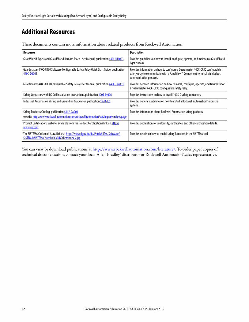
Safety Function: Light Curtain with Muting (Two Sensor L-type) and Configurable Safety Relay
Additional Resources
These documents contain more information about related products from Rockwell Automation.
You can view or download publications at http://www.rockwellautomation.com/literature/. To order paper copies of technical documentation, contact your local Allen-Bradley® distributor or Rockwell Automation® sales representative.
Resource Description
GuardShield Type 4 and GuardShield Remote Teach User Manual, publication 440L-UM003 Provides guidelines on how to install, configure, operate, and maintain a GuardShield light curtain.
Guardmaster 440C-CR30 Software Configurable Safety Relay Quick Start Guide, publication 440C-QS001
Provides information on how to configure a Guardmaster 440C-CR30 configurable safety relay to communicate with a PanelView™ Component terminal via Modbus communication protocol.
Guardmaster 440C-CR30 Configurable Safety Relay User Manual, publication 440C-UM001 Provides detailed information on how to install, configure, operate, and troubleshoot a Guardmaster 440C-CR30 configurable safety relay.
Safety Contactors with DC Coil Installation Instructions, publication 100S-IN006 Provides instructions on how to install 100S-C safety contactors.
Industrial Automation Wiring and Grounding Guidelines, publication 1770-4.1 Provides general guidelines on how to install a Rockwell Automation® industrial system.
Safety Products Catalog, publication S117-CA001website http://www.rockwellautomation.com/rockwellautomation/catalogs/overview.page
Provides information about Rockwell Automation safety products.
Product Certifications website, available from the Product Certifications link on http://www.ab.com
Provides declarations of conformity, certificates, and other certification details.
The SISTEMA Cookbook 4, available at http://www.dguv.de/ifa/Praxishilfen/Software/ SISTEMA/SISTEMA-Kochb%C3%BCcher/index-2.jsp
Provides details on how to model safety functions in the SISTEMA tool.
52 Rockwell Automation Publication SAFETY-AT136C-EN-P - January 2016

Safety Function: Light Curtain with Muting (Two Sensor L-type) and Configurable Safety Relay
Notes:
Rockwell Automation Publication SAFETY-AT136C-EN-P - January 2016 53

Allen-Bradley, Connected Components Workbench, Guardmaster, GuardShield, LISTEN. THINK. SOLVE., PanelView, PHOTOSWITCH, RightSight, Rockwell Automation, Rockwell Software, and SensaGuard are trademarks of Rockwell Automation, Inc.
Trademarks not belonging to Rockwell Automation are property of their respective companies.
Publication SAFETY-AT136C-EN-P - January 2016 Supersedes Publication SAFETY-AT136B-EN-P - May 2015 Copyright © 2016 Rockwell Automation, Inc. All rights reserved. Printed in the U.S.A.
Documentation Feedback
Your comments will help us serve your documentation needs better. If you have any suggestions on how to improve this document, complete this form, publication RA-DU002, available at http://www.rockwellautomation.com/literature/.
Rockwell Otomasyon Ticaret A.Ş., Kar Plaza İş Merkezi E Blok Kat:6 34752 İçerenköy, İstanbul, Tel: +90 (216) 5698400
For more information onSafety Function Capabilities, visit:http://marketing.rockwellautomation.com/safety/en/safety_functions
Rockwell Automation maintains current product environmental information on its website athttp://www.rockwellautomation.com/rockwellautomation/about-us/sustainability-ethics/product-environmental-compliance.page.